Digital Lighting Management -...
12
800.879-8585 www.wattstopper.com ©2011 WattStopper Table of Contents D i g i t a l L i g h t i n g M a n a g e m e n t This addendum shows you how to install, configure and use a WattStopper Digital Lighting Management (DLM) system segment network. Carefully read all instructions provided with products. This addendum assumes you are familiar with the features, products and installation practices used in a DLM system based on LMRC-1xx, LMRC-2xx, or LMRC-3xx series room controllers in a local network. If you have not received training for installation of a DLM local network system, you should read the DLM System Installation Guide and DLM Dimming System Addendum before installing a DLM segment network. To download complete DLM system guides go to: www.wattstopper.com -> Resources-> Downloads-> Installation Instructions-> Digital Lighting Management. All wiring must comply with applicable electrical and safety codes. All electrical installation work should be carried out by an experienced electrician. DLM System Networking Addendum SYSTEM OVERVIEW Digital Lighting Management: Segment Network ....................................2 Introduction ............................................. 2 Planning The Network.................................2 Local Network Setup and Configuration ....2 DLM Segment Network Layout Examples ..3 SEGMENT NETWORK CONNECTIONS Installing the Segment Network to the Local Network Rooms..............................4 Network Activity LEDs ............................. 4 NETWORK COMMUNICATION BACnet Communication ..............................5 BACnet Object List .................................. 5 CONFIGURATION TOOL LMCT-100 Digital IR Configuration Tool .....6 ROOM CONTROLLERS Dimming Room Controllers with Network Bridge .......................................6 Power Monitoring .................................... 6 NETWORK BRIDGE MODULE LMBC-300 Network Bridge Module ............7 Wiring to Local Network ........................ 7 Wiring to Network ................................... 7 Termination Resistor .............................. 8 SEGMENT MANAGER LMSM-201 and LMSM-603 Segment Manager ....................................9 Features ................................................ 10 Specifications ........................................ 11 Installation and Operating Instructions 11 NOTICES Safety ......................................................... 12 Patents ....................................................... 12 Warranty Information ................................ 12
Transcript of Digital Lighting Management -...

800.879-8585
www.wattstopper.com
©2011 WattStopper
Table of Contents
D i g i t a l L i g h t i n g M a n a g e m e n t
This addendum shows you how to install, configure and use a WattStopper Digital Lighting Management (DLM) system segment network. Carefully read all instructions provided with products. This addendum assumes you are familiar with the features, products and installation practices used in a DLM system based on LMRC-1xx, LMRC-2xx, or LMRC-3xx series room controllers in a local network. If you have not received training for installation of a DLM local network system, you should read the DLM System Installation Guide and DLM Dimming System Addendum before installing a DLM segment network. To download complete DLM system guides go to: www.wattstopper.com -> Resources-> Downloads-> Installation Instructions-> Digital Lighting Management.
All wiring must comply with applicable electrical and safety codes. All electrical installation work should be carried out by an experienced electrician.
DLM System Networking Addendum
! SYSTEM OVERVIEW Digital Lighting Management:
Segment Network ....................................2Introduction ............................................. 2
Planning The Network .................................2Local Network Setup and Configuration ....2DLM Segment Network Layout Examples ..3
! SEGMENT NETWORK CONNECTIONS Installing the Segment Network to the
Local Network Rooms..............................4Network Activity LEDs ............................. 4
NETWORK COMMUNICATIONBACnet Communication ..............................5
BACnet Object List .................................. 5
! CONFIGURATION TOOLLMCT-100 Digital IR Configuration Tool .....6
! ROOM CONTROLLERSDimming Room Controllers with
Network Bridge .......................................6Power Monitoring .................................... 6
! NETWORK BRIDGE MODULELMBC-300 Network Bridge Module ............7
Wiring to Local Network ........................ 7Wiring to Network ................................... 7Termination Resistor .............................. 8
! SEGMENT MANAGERLMSM-201 and LMSM-603
Segment Manager ....................................9Features ................................................ 10Specifications ........................................ 11Installation and Operating Instructions 11
! NOTICESSafety .........................................................12Patents .......................................................12Warranty Information ................................12

2
! System Overview
IntroductionDigital Lighting Management local network rooms and LILM Lighting Integrator relay panels can be interconnected via the DLM segment network. This allows management of the entire DLM system from a web browser based user interface served from the DLM Segment Manager, or from a BACnet-based Building Automation System (BAS).
Each DLM segment network supports up to a maximum of 96 local network rooms and/or LILM relay panels on a single network segment.
A single DLM network bridge installed in each local network allows connection between rooms and exposes DLM parameters as BACnet objects to create the segment network. The DLM network bridge is available as either a stand-alone LMBC-300 module or integrated into an LMRC-3xx series room controller.
The Segment Manager is a building controller that can support one, two or three independent segment networks depending on the model that is used. This architecture allows up to 288 rooms and/or panels to be networked together using a single Segment Manager.
DIGITAL LIGHTING MANAGEMENT: SEGMENT NETWORK
PLANNING THE NETWORKThe DLM segment network is based on RS485 digital networking technology. The wire must be installed in a linear path (aka: daisy chain) between all of the connected devices. With linear topology, the segment network wire can have only two ends. It is not permissible to use “Y”, “T” or star connections anywhere on the segment. Using the proper wire, each segment network can extend up to 4000 linear feet. If using the LMSM-603 with three segments, the installation can use a total of 12,000 feet of wire.
LM-MSTP4,000 feet max.
per segment network
SegmentManageror BAS
LocalNetwork
Room
LILMRelayPanel
LocalNetwork
Room
It is a good practice to not “max out” the wire runs. If your installation requires close to 4000 feet of network wire, it is recommended that you use the LMSM-603 segment manager and use two or more segments. It is also strongly recommended to use WattStopper model LM-MSTP wire or an exact equivalent that is rated for RS485 networks.
The segment manager can be placed at the end of the segment network as shown in the previous block diagram, or it can be located anywhere along the linear network. On a single segment installation this topology allows two home runs to the segment manager as shown in the top example on the following page.
Using the LMSM-603 with three segments, allows a potential for up to six segment network home runs. This would be three segments with the segment manager located in the middle of each segment.
LOCAL NETWORK SETUP AND CONFIGURATIONAs with all DLM systems, local network rooms are automatically configured upon power-up using the WattStopper patented Plug n’ Go™ configuration to allow basic operation of all DLM devices to maximize energy efficiency. For customization, use the Push n’ Learn function as described in the DLM System Installation Guide, Dimming System Addendum, Quick Start Guide provided with the device, or the manual for the configuration tool that you are using, such as the LMCT-100 or LMCS-100.
LMSM-201 Segment Manager

DLM Networking System Addendum 3
System Overview
DLM SEGMENT NETWORK LAYOUT EXAMPLES
Maximum single-segment configuration example
Multiple DLM Local Networks connected to a Single Segment Network
DLM Segment Network = 4000’ max for a single segmentMaximum 96 DLM local network rooms or LILM relay panels (or combination thereof) per segment.One segment connection per local network room via LMBC-300, LMRC-3xx room controller, or LILM panel.
120 120 Ohm end-of-line resistor required between the - and + wires connected to the last DLM segment network device at each end of the MS/TP segment.
LMRJ Cables
Loads
1
2
Line Voltage
LMRC-102Room
Controller
J-Box
OccupancySensor
Switch
Segment Network (LM-MSTP Wire)
SegmentManager
Toadditional DLM Local Networks
LMBC-300Network Bridge
(linear topology dataline)
Local Network 1
Line Voltage
Line Voltage
J-Box
OccupancySensor
LMRC-312Dimming
RoomControllerw/network
bridge
Scene Switch Dimming Switch
Class 2 0-10 Volt Control Wiring
0-10 VoltBallast
0-10 VoltBallast
LMRJ Cables
Local Network 2Plug LoadController
LMPL-101J-Box
120VAC LILM Panel
#1, room
Segment Network
LM-MSTP wire
#2, room
#3, room#4, public space#127, room
Linear topology (daisy-chain) dataline
LMBC-300 LMRC-312
DLMLocal
NetworkDLMLocal
Network
LMRC-313LMRC-311 LILM Panel
Segment Manager
Ethernet cable toLAN, PC or BAS
DLMLocal
Network
DLMLocal
Network
120
120
120
120

4
INSTALLING THE SEGMENT NETWORK TO THE LOCAL NETWORK ROOMSThe DLM segment network has only a single connection to each local network room regardless of the number of sensors, switches, and room controllers installed as part of the room. The network connection to the room is made through either the LMRC-3xx series room controller that contains the network bridge or through the LMBC-300 network bridge module.
Refer to the Quick Start Guide and Installation Instructions that are provided with the LMRC-3xx series room controller or LMBC-300 Network Bridge Module for installation of these devices into the room’s local network.
The LMRC-3xx series room controllers and the LMBC-300 each have a three position terminal block provided for connection of the segment network. The terminals are labeled +, -, and Reference. The white wire connects to the positive (+) terminal, the black wire connects to the negative (-) terminal and the green with white stripe connects to the Reference (R) terminal. The bare twisted strand conductor in the network cable is shield.
Do NOT connect the shield conductor to the room controller or network bridge module. The bare twisted (or braided) shield conductor connects to the earth ground at the segment manager.
The shield conductor must maintain continuity along the entire length of the segment wire. Wherever connections are being made to the room controller or network bridge module, the shield conductors should be twisted together and secured. See the illustrations below:
.
! Segment Network Connections
LMBC-300 Network Bridge Module
Black ( – )
White (+)
Green (R)
Segment Network MS/TP
To nextdevice
Frompreviousdevice
Wrap shieldwires aroundcable ends
Tape downsecurely
12440r2
Connect toWattStopper
Digital LightingManagement
Class 2 power source.
Transmit
Receive
www.wattstopper.com
Connect to DLM local network only NOT Ethernet
Pat. Pend.
Config.LED
Refe
renc
e
– +Segm
ent
Netw
ork
Term
inal
s
1253
2r1
0-10V Dimming Control Outputs
Load
A
Load
BVi
olet
+
Grey
-
Viol
et +
Grey
-
Segment Network
Tran
smit
Rece
ive
120/277VAC, 50/60Hz, Output: 250mAMaximum load, each relay: Ballast or incandescent load: 20A Motor load: 1HP@120VACMaximum combined load: 20ATwo 0-10V dimming outputs Class 2 output
UL 2043 Plenum Rated
Digital Dual Relay Room Controllerwith Network BridgeLMRC-312
Santa Clara,
12523r1
APPLIANCECONTROL
88T9
Black ( – )
White (+)
Green (R)
Network Activity LEDsAs room controllers and/or network bridge modules are connected to the network wire, the red Transmit LED should blink rapidly on these devices. As network messages are received, the green Receive LED should begin to blink rapidly. It is recommended practice to check this behavior as each device is added to the network.

DLM Networking System Addendum 5
The Network Bridge automatically inventories the local network and presents readable and writable device parameters as standard BACnet objects.
The LMBC-300 is a standard MS/TP master device. The MS/TP MAC address is automatically configured through arbitration with other devices on the network, however these are writable parameters. The factory default baud rate is 38,400. The factory default device ID is the last six digits of the LMBC-300’s serial number. The device instance, description property and location properties are also writable.
LMRC-311, LMRC-312, and LMRC-313 room controllers have the network bridge functionality built-in and do not require the separate LMBC-300 network bridge module. These room controllers combine all the features of the LMBC-300 and LMRC-211/212/213 Room Controllers, including current monitoring of the connected load, integrated within a single housing.
BACnet Object List
Object Instance
Object Alias Object Function
BO1 - BO64 Loads 1-64, state Relay state, internally linked to the Analog Output objects by the trip point parameter. Relay is ON above trip point and OFF below trip point. Default trip point is 50% for LMRC-100 Series room controllers and and 1% for LMRC-200 and -300 Series room controllers.
AO1 - AO64 Loads 1-64, level Dimming level, internally linked to the Binary Output objects by the trip point parameter. Range = 0 to100%.
BI101 - BI4808 Button state Read button state for 1 to 8 buttons per switch for 1 to 48 switches.
AV501 - 548 Total electrical current Read total current "owing through the room controller in amps, for room controller 1 to 48.
BI1-BI48 Detection state Occupancy sensor detection state. Active = occupied.
AV401 - 448 Input voltage Per room controller, written by the user, default is 0.
AV1 - AV48 Total wattage Calculated based on the input voltage and measured current for room controller 1 to 48.
AV101 -AV148 Occupancy sensor 1-48, time delay
For occupancy sensor 1 to 48 in seconds, 0 to 30 minutes.
AV201 - AV248 Occupancy sensor 1-48, PIR sensitivity
Per PIR (passive infrared) sensor, 0 to 100% in percent, 10% resolution.
AV301 - AV348 Occupancy sensor 1-48, ultrasonic sensitivity
Per ultrasonic sensor, 0 to 100% in percent, 10% resolution.
AI4001-AI4048 Daylight sensor 1-48, light level
Interior footcandle level as read by LMLS-400 daylight sensor 1 to 48.
AI5001-AI5048 Daylight sensor 1-48, light level
Interior footcandle level as read by LMLS-500 daylight sensor 1 to 48.
AV4101-AV4148
Daylight sensor fade/delay time 1-48
For LMLS-400 daylight sensor 1 to 48, fade up time 1 to 60 seconds for dimming, OFF setpoint delay 180 to 1800 seconds for switching.
AV4201-AV4248
Daylight sensor 1-48, setpoint
For LMLS-400 daylight sensor 1 to 48, day setpoint for dimming, ON setpoint for switch-ing, in footcandles.
AV4301-AV4348
Daylight sensor 1-48, setpoint
For LMLS-400 daylight sensor 1 to 48, night setpoint for dimming, OFF setpoint for switching, in footcandles.
MV4001-MV4048
Daylight sensor 1-48, operating mode
For LMLS-400 daylight sensor 1-48, operation mode: 0 = ON/OFF, 1 = bi-level, 2 = tri-level, 3 = dimming.
BV1 Schedule state Normal hours/after hours selection. Active = after hours.
BV2 Switch lock control Lock or unlock enabled switches. Active = lock.
BV101-148 Switch lock status Read switch status (locked or unlocked). Active = locked.
MV1 Scene control Write scene selection. Range = 1 to 16.
AI1 - AI48 Exterior photocell Daylight level as read by LMIO-301 photocell input module 1 to 48.
AV901 MS/TP MAC address Default is 255 for automatic, writable in the range of 0 to127.
AV902 Network speed Baud rate: 9600, 19200, 38400, 57600, 76800, 115200.
BACNET COMMUNICATION
! Network Communication
6
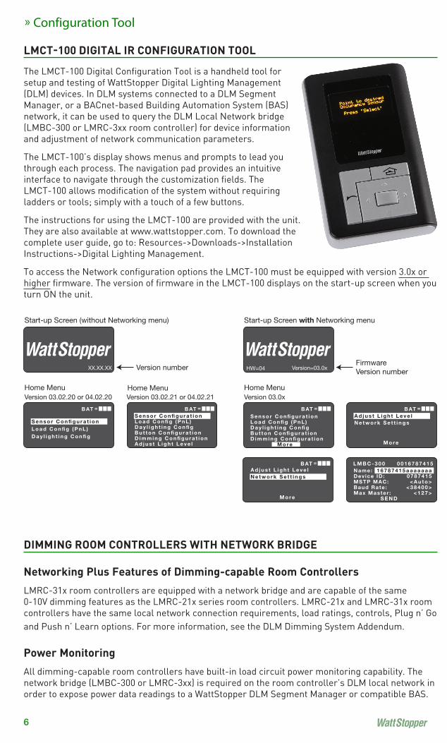
! Configuration Tool LMCT"100 DIGITAL IR CONFIGURATION TOOL
The LMCT-100 Digital Configuration Tool is a handheld tool for setup and testing of WattStopper Digital Lighting Management (DLM) devices. In DLM systems connected to a DLM Segment Manager, or a BACnet-based Building Automation System (BAS) network, it can be used to query the DLM Local Network bridge (LMBC-300 or LMRC-3xx room controller) for device information and adjustment of network communication parameters.
The LMCT-100’s display shows menus and prompts to lead you through each process. The navigation pad provides an intuitive interface to navigate through the customization fields. The LMCT-100 allows modification of the system without requiring ladders or tools; simply with a touch of a few buttons.
The instructions for using the LMCT-100 are provided with the unit. They are also available at www.wattstopper.com. To download the complete user guide, go to: Resources->Downloads->Installation Instructions->Digital Lighting Management.
To access the Network configuration options the LMCT-100 must be equipped with version 3.0x or higher firmware. The version of firmware in the LMCT-100 displays on the start-up screen when you turn ON the unit.
DIMMING ROOM CONTROLLERS WITH NETWORK BRIDGE
Networking Plus Features of Dimming-capable Room ControllersLMRC-31x room controllers are equipped with a network bridge and are capable of the same 0-10V dimming features as the LMRC-21x series room controllers. LMRC-21x and LMRC-31x room controllers have the same local network connection requirements, load ratings, controls, Plug n’ Go and Push n’ Learn options. For more information, see the DLM Dimming System Addendum.
Power MonitoringAll dimming-capable room controllers have built-in load circuit power monitoring capability. The network bridge (LMBC-300 or LMRC-3xx) is required on the room controller’s DLM local network in order to expose power data readings to a WattStopper DLM Segment Manager or compatible BAS.
XX.XX.XX Version number
Start-up Screen (without Networking menu)
Version 03.02.20 or 04.02.20Home Menu
S e n s o r C o n fi g u r a t i o nL o a d C o n fi g ( P n L )D a y l i g h t i n g C o n fi g
=B ATS e n s o r C o n fi g u r a t i o nL o a d C o n fi g ( P n L )D a y l i g h t i n g C o n fi gB u t t o n C o n fi g u r a t i o nD i m m i n g C o n fi g u r a t i o nA d j u s t L i g h t L e v e l
=B AT
Version 03.02.21 or 04.02.21
Version=03.0xFirmwareVersion number
Start-up Screen with Networking menu
Version 03.0xHome Menu
=B ATA d j u s t L i g h t L e v e lN e t w o r k S e t t i n g s
M o re
=B AT
A d j u s t L i g h t L e v e lN e t w o r k S e t t i n g s
M o re
=B ATName:Device ID: MSTP MAC:Baud Rate :Max Master : S E N D
1 6 7 8 7 4 1 5 a a a a a a a0 7 8 7 4 1 5
< A u t o >< 3 8 4 0 0 >
< 1 2 7 >
L M B C - 3 0 0 0 0 1 6 7 8 7 4 1 5
HW=04
S e n s o r C o n fi g u r a t i o nL o a d C o n fi g ( P n L )D a y l i g h t i n g C o n fi gB u t t o n C o n fi g u r a t i o nD i m m i n g C o n fi g u r a t i o n M o re
Home Menu

DLM Networking System Addendum 7
» Network Bridge Module
LMBC"300 NETWORK BRIDGE MODULEThe LMBC-300 Network Bridge module provides a network connection for a group of WattStopper Digital Lighting Management (DLM) Local Network room level devices. The DLM local network must include at least one LMRC-10x series or one LMRC-2xx series room controller. Connecting the LMBC-300 to the DLM local network then to either the DLM Segment Manager or a third party system using the BACnet protocol exposes the status and parameters of all connected devices to the broader network.
WIRING to Local Network The LMBC-300 can connect anywhere on the DLM local network using LMRJ cables. Use a WattStopper LMRJ series cable or a Cat5e patch cable to connect the LMBC-300 to one of the RJ-45 jacks on any of the DLM local network devices. When connected to a powered DLM local network the red Transmit LED blinks rapidly. The red Config LED blinks at the same rate as the other DLM local network devices.
WARNING: Connect the LMBC-300 RJ-45 jack only to DLM lighting control devices. Do not connect Ethernet to the LMBC-300 RJ-45 jack.
Wiring to Network1. Connect the LM-MSTP network wire to the Segment Network
Terminals on the LMBC-300, observing positive (+) and negative (-) polarity.
In WattStopper LM-MSTP series wire, positive is the white conductor and negative is the black. Reference connects to the green wire.
Do not connect the shield conductor of the LM-MSTP wire to the LMBC-300 module. When making an in and out connection to the LMBC-300, the shield conductor must be twisted together and secured external to the LMBC terminals such that the shield maintains continuity for the entire length of the network.
The shield conductor should be connected to the earth ground at the Segment Manager only.
2. With the network terminals connected to an active network, both the red Transmit and green Receive LEDs blink rapidly.
Segment NetworkToSegment Manager
or BAS
LMRJ Cables
Loads
1
2
Line VoltageLMRC-102Room
Controller
J-Box
OccupancySensor
Switch
LMBC-300Network Bridge
Toadditional DLM
Local Networks
LM-MSTP Wire
(linear topology dataline)
Attach the LMRJ Local Network Cable
Black ( – )
White (+)
Green (R)
Segment Network MS/TP
To nextdevice
Frompreviousdevice
Wrap shieldwires aroundcable ends
Tape downsecurely
12440r2
Connect toWattStopper
Digital LightingManagement
Class 2 power source.
Transmit
Receive
www.wattstopper.com
Connect to DLM local network only NOT Ethernet
Pat. Pend.
Config.LED
Refe
renc
e
– +Segm
ent
Netw
ork
Term
inal
s

8
Termination ResistorThe last device on each end of a segment network wire run must have a termination resistor. 120 ohm resistors are provided with the LMSM-201 and LMSM-603 for this purpose.
If the LMBC-300 is the last device on the segment wire run, connect the resistor between the LMBC-300 positive (+) and negative (-) terminals.
When the LMBC-300 is the last DLM segment network device on the wire run, cap or tape the shield conductor to isolate it from ground or other contact.
SpecificationsVoltage. . . . . . . . . . . . . . . . . . . . . . . . . . . . . . . . . . . . . . . . . . . . . . . . . . . . . . . . . . . . . . . . . . . . . . . . 24VDCCurrent Consumption . . . . . . . . . . . . . . . . . . . . . . . . . . . . . . . . . . . . . . . . . . . . . . . . . . . . . . . . . . . . 21mAPower Supply . . . . . . . . . . . . . . . . . . . . . . . . . . . . . . . . . . . . . . . . . . . . . WattStopper Room ControllersConnection to DLM Local Network . . . . . . . . . . . . . . . . . . . . . . . . . . . . . . . . . . . . . . . . . . 2 RJ-45 portsSegment Network . . . . . . . . . . . . . . . .Conforms to BACnet MS/TP master communication protocol Baud rates, selectable. . . . . . . . . . . . . . 38,400 standard, 9600, 19,200, 57,600, 76,800, 115,200 Environment . . . . . . . . . . . . . . . . . . . . . . . . . . . . . . . . . . . . . . . . . . . . . . . . . . . . . . . . For Indoor Use Only Operating Temperature. . . . . . . . . . . . . . . . . . . . . . . . . . . . . . . . . . . . . . . . . 32° to 158°F (0° to 70°C) Storage Temperature . . . . . . . . . . . . . . . . . . . . . . . . . . . . . . . . . . . . . . . . . 23° to 176°F (-5° to 80°C) Relative Humidity . . . . . . . . . . . . . . . . . . . . . . . . . . . . . . . . . . . . . . . . . . . . 5 to 95% (non condensing) UL2043 Plenum ratedRoHS compliant
Black ( – )
White (+)
Green (R)
120 OhmResistor
Last device onMS/TP wire run
12440r2
Connect toWattStopper
Digital LightingManagement
Class 2 power source.
Transmit
Receive
www.wattstopper.com
Connect to DLM local network only NOT Ethernet
Pat. Pend.
Config.LED
Refe
renc
e
– +Segm
ent
Netw
ork
Term
inal
s
Segment Network MS/TP
Wrap shieldwires aroundcable ends
Tape downsecurely
! Network Bridge Module
LMBC"300 MODULE continued

DLM Networking System Addendum 9
The Digital Lighting Management (DLM) Network Segment Manager is a network controller designed for use with DLM local networks and/or LILM lighting control panels. The Segment Manager provides global control, monitoring, adjustment, and scheduling functionality for networked DLM systems across multiple rooms and buildings.
The Segment Manager communicates with the DLM local networks and panels over a BACnet-compatible digital segment network. The LMSM-201 supports one segment network while the LMSM-603 supports three segment networks.
Each segment network can include up to 96 DLM local networks, or LILM panels. The user interface is hosted by the Segment Manager and is served up over a TCP/IP connection. The interface is available on any PC using a compatible web browser.
» Segment Manager
LMSM"201 AND LMSM"603 SEGMENT MANAGER
Barrel power connector
Ground wire
PC or LAN
SegmentNetwork
White (+)Green (R)
Black ( – )
White (+)
-+R -+R
Black ( – )
White (+)
Black ( – )
**
Green (R) Green (R)
* Connect a 120 ohm resistor between - and + wires on the last DLM MS/TP network device located at opposite ends of the segment. Wrap and tape unconnected shield conductors at the end of the segment.
Connect the shield conductors from all network segments to earth ground at the segment manager. The LMSM-ENC1 enclosure provides a ground lug for this purpose and is recommended. Do not connect the shield conductor(s) at any other device.
*

10
! Segment Manager
LMSM SEGMENT MANAGER continued
Users can easily monitor and adjust DLM device parameters from the convenience of a PC connected to a Segment Manager. This includes occupancy and daylighting sensor settings, load parameters, digital switch button configuration and dimming parameters. Normal and after hours parameters can be set or adjusted and users can create seven-day-repeating or calendar-event-based schedules. Additionally, power consumption may be monitored in real time for areas equipped with LMRC-2xx and/or -3xx Room Controllers and/or LMPL-201 Plug Load Room Controllers.
The Segment Manager is an ideal solution when remote access to DLM local networks is desired. It is suitable for schools, office buildings, or other applications that will benefit from the ability to adjust settings and calibrations without the need to physically visit each room. It is also recommended for projects that require automatic reconfiguration of device settings based on a schedule.
Features
Internet
Room Controllers in real time
network device settings and states

DLM Networking System Addendum 11
Specifications
- LMSM-201: one segment network - LMSM-603: three segment networks
- WattStopper LM-MSTP wire, or equivalent rated for BACnet MS/TP (RS485) - Linear topology; 4000’ maximum per segment - Up to 96 local networks or panels per segment
RoHS compliant
Installation and Operating InstructionsA complete set of installation instructions and an operation manual are provided with the Segment Manager and this information is also available on line at www.wattstopper.com.
LMSM SEGMENT MANAGER continued
» Segment Manager

12
NOTICESFor Class 2 DLM Devices
WARNING: Do Not install to cover a Junction Box Having Class 1, 3 or Power and Lighting Circuits.
SAFETY
WARNING: Do not use the DLM system to control loads other than lighting if the load is not in view of a person at all control locations. Do not use DLM to control any load that might be dangerous or cause a hazardous situation if accidentally activated.
CAUTION: Turn the power off at the circuit breaker or remove the fuse before working on any electrical wiring.
PATENTSThe system and products described in this guide may be covered by one or more of the following
WARRANTY INFORMATIONWattStopper warranties its products to be free of defects in materials and workmanship for a period of five (5) years. There are no obligations or liabilities on the part of WattStopper for consequential damages arising out of, or in connection with, the use or performance of this product or other indirect damages with respect to loss of property, revenue or profit, or cost of removal, installation or reinstallation.
Please Recycle
2800 De La Cruz Blvd. Santa Clara, CA 95050
Phone: 800.879.8585 www.wattstopper.com ©2011 WattStopper
13831r1 6/10/2011
Digital Lighting Management System
12