DIGITAL KEY TELEPHONE SYSTEM GENERAL DESCRIPTION · general description strata dk8 & dk16 august...
46
DIGITAL KEY TELEPHONE SYSTEM GENERAL DESCRIPTION © COPYRIGHT 1993 TOSHIBA AMERICA INFORMATION SYSTEMS, INC. All rights reserved. No part of this manual, covered by the copyrights hereon, may be reproduced in any form or by any means—graphic, electronic, or mechanical, including recording, taping, photocopy- ing, or information retrieval systems—without express written permission of the publisher of this material. GENERAL DESCRIPTION TOSHIBA SYSTEM PRACTICES DIGITAL KEY TELEPHONE SYSTEMS STRATA DK8 & DK16 AUGUST 1993 Version 1.2
Transcript of DIGITAL KEY TELEPHONE SYSTEM GENERAL DESCRIPTION · general description strata dk8 & dk16 august...
DIGITAL KEY TELEPHONE SYSTEM
GENERAL DESCRIPTION
© COPYRIGHT 1993 TOSHIBA AMERICA INFORMATION SYSTEMS, INC.
All rights reserved. No part of this manual, covered by the copyrights hereon, may be reproduced inany form or by any means—graphic, electronic, or mechanical, including recording, taping, photocopy-ing, or information retrieval systems—without express written permission of the publisher of thismaterial.
GENERAL DESCRIPTION
TOSHIBA SYSTEM PRACTICES DIGITAL KEY TELEPHONE SYSTEMS
S T R A T A D K 8 & D K 1 6 A U G U S T 1 9 9 3
Version 1.2

tion to the above, certain features (Off-premisesStations, etc.) may also require Hybrid telephonesystem registration in some areas.
If you are unsure of your type of operaiton and/orthe appropriate FCC registration number, contactyour local Toshiba telecommunications distributorfor assistance.
STRATA DK8 DKSU Manufactured in Malaysia:Key system: CJ6MLA-74479-KF-EHybrid: CJ6MLA-74478-MF-E
STRATA DK16 DKSU Manufactured in Singapore:Key system: CJ6SNG-73672-KF-EHybrid: CJ6SNG-73673-MF-E
3. Ringer equivalence number: 0.2B. The ringer equiva-lence number (REN) is useful to determine the quantityof devices which you may connect to your telephoneline and still have all of those devices ring when yournumber is called. In most areas, but not all, the sum ofthe RENs of all devices connected to one line shouldnot exceed five (5.0B). To be certain of the number ofdevices you may connect to your line, as determinedby the REN, you should contact your local telephonecompany to ascertain the maximum REN for your call-ing area.
4. Network connection information USOC jack required:RJ11, RJ14C, RJ21X (see Table C).
Items 2, 3 and 4 above are also indicated on the equip-ment label.
RADIO FREQUENCY INTERFERENCEWarning: This equipment generates, uses, and can radiate
radio frequency energy and if not installed and used inaccordance with the manufacturer’s instruction manual, maycause interference to radio communications. It has beentested and found to comply with the limits for a Class A com-puting device pursuant to Subpart J of Part 15 of FCCRules, which are designed to provide reasonable protectionagainst such interference when operated in a commercialenvironment. Operation of this equipment in a residentialarea is likely to cause interference, in which case, the user,at his own expense, will be required to take whatever mea-sures may be required to correct the interference.
This system is listed with Underwriters Laboratory.
UL Requirement: If wiring from any telephoneexits the building or is subject to lightning or otherelectrical surges, then secondary protection isrequired. (See Installation & Maintenance Manualfor more information.)
The STRATA DK8 and DK16 Digital Key tele-phone system is registered in accordance with theprovisions of Part 68 of the Federal CommunicationsCommission’s Rules and Regulations.
FCC REQUIREMENTSMeans of Connection: The Federal Communications
Commission (FCC) has established rules which permit theSTRATA DK system to be connected directly to the tele-phone network. Connection points are provided by the tele-phone company—connections for this type of customer-provided equipment will not be provided on coin lines.Connections to party lines are subject to state tariffs.
Incidence of Harm: If the system is malfunctioning, it mayalso be disrupting the telephone network. The systemshould be disconnected until the problem can be deter-mined and repaired. If this is not done, the telephone com-pany may temporarily disconnect service. If possible, theywill notify you in advance, but, if advance notice is notpractical, you will be notified as soon as possible. You willbe informed of your right to file a complaint with the FCC.
Service or Repair: For service or repair, contact your localToshiba telecommunications distributor. To obain the near-est Toshiba telecommunications distributor in your area,call Toshiba America Information Systems, Inc.,Telecommunication Systems Division in Irvine, CA (714)583-3700.
Telephone Network Compatibility: The telephone companymay make changes in its facilities, equipment, operations,and procedures. If such changes affect the compatibility oruse of the STRATA DK system, the telephone company willnotify you in advance to give you an opportunity to main-tain uninterrupted service.
Notification of Telephone Company: Before connecting aSTRATA DK system to the telephone network, the tele-phone company may request the following:
1. Your telephone number.
2. FCC registration number: STRATA DK may be configured as a Key or Hybrid
telephone system. The appropriate configuration foryour system is dependent upon your operation ofthe system.
If the operation of your system is only manual selec-tion of outgoing lines, it may be registered as a Keytelephone system.
If your operation requires automatic selection ofoutgoing lines, such as dial access, Least CostRouting, Pooled Line Buttons, etc., the system mustbe registered as a Hybrid telephone system. In addi-
STRATA DK8 AND DK16
GENERAL END USER INFORMATION
IMPORTANT NOTICE—MUSIC-ON-HOLDIn accordance with U.S. Copyright Law, a license may be required from the American Society of Composers, Authors andPublishers, or other similar organization, if radio or TV broadcasts are transmitted through the music-on-hold feature of thistelecommunication system. Toshiba America Information Systems, Inc., hereby disclaims any liability arising out of the failure toobtain such a license.
UL®
LISTED
49L7E88891
GENERAL DESCRIPTION
S T R A T A D K 8 & D K 1 6 A U G U S T 1 9 9 3
i
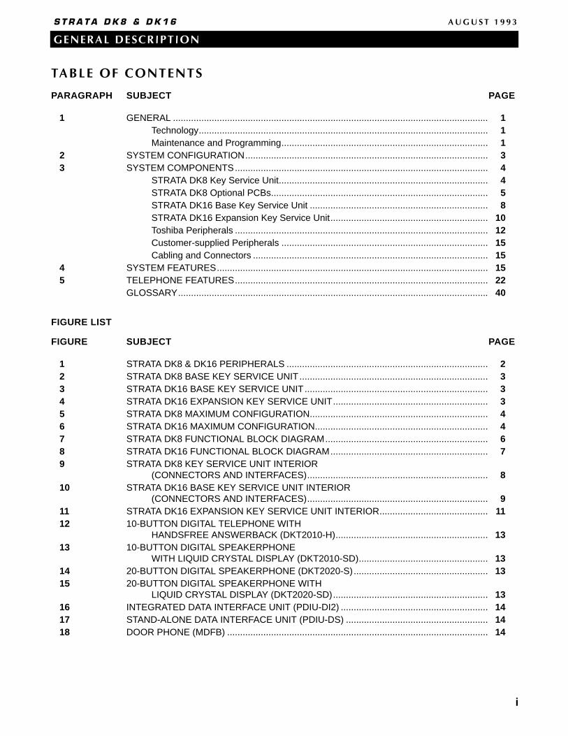
TABLE OF CONTENTS
PARAGRAPH SUBJECT PAGE
1 GENERAL .......................................................................................................................... 1Technology................................................................................................................ 1Maintenance and Programming................................................................................ 1
2 SYSTEM CONFIGURATION.............................................................................................. 33 SYSTEM COMPONENTS.................................................................................................. 4
STRATA DK8 Key Service Unit................................................................................. 4STRATA DK8 Optional PCBs.................................................................................... 5STRATA DK16 Base Key Service Unit ..................................................................... 8STRATA DK16 Expansion Key Service Unit............................................................. 10Toshiba Peripherals .................................................................................................. 12Customer-supplied Peripherals ................................................................................ 15Cabling and Connectors ........................................................................................... 15
4 SYSTEM FEATURES......................................................................................................... 155 TELEPHONE FEATURES.................................................................................................. 22
GLOSSARY........................................................................................................................ 40
FIGURE LIST
FIGURE SUBJECT PAGE
1 STRATA DK8 & DK16 PERIPHERALS .............................................................................. 22 STRATA DK8 BASE KEY SERVICE UNIT......................................................................... 33 STRATA DK16 BASE KEY SERVICE UNIT....................................................................... 34 STRATA DK16 EXPANSION KEY SERVICE UNIT............................................................ 35 STRATA DK8 MAXIMUM CONFIGURATION..................................................................... 46 STRATA DK16 MAXIMUM CONFIGURATION................................................................... 47 STRATA DK8 FUNCTIONAL BLOCK DIAGRAM............................................................... 68 STRATA DK16 FUNCTIONAL BLOCK DIAGRAM............................................................. 79 STRATA DK8 KEY SERVICE UNIT INTERIOR
(CONNECTORS AND INTERFACES)...................................................................... 810 STRATA DK16 BASE KEY SERVICE UNIT INTERIOR
(CONNECTORS AND INTERFACES)...................................................................... 911 STRATA DK16 EXPANSION KEY SERVICE UNIT INTERIOR.......................................... 1112 10-BUTTON DIGITAL TELEPHONE WITH
HANDSFREE ANSWERBACK (DKT2010-H)........................................................... 1313 10-BUTTON DIGITAL SPEAKERPHONE
WITH LIQUID CRYSTAL DISPLAY (DKT2010-SD).................................................. 1314 20-BUTTON DIGITAL SPEAKERPHONE (DKT2020-S).................................................... 1315 20-BUTTON DIGITAL SPEAKERPHONE WITH
LIQUID CRYSTAL DISPLAY (DKT2020-SD)............................................................ 1316 INTEGRATED DATA INTERFACE UNIT (PDIU-DI2) ......................................................... 1417 STAND-ALONE DATA INTERFACE UNIT (PDIU-DS) ....................................................... 1418 DOOR PHONE (MDFB) ..................................................................................................... 14

ii
GENERAL DESCRIPTION
S T R A T A D K 8 & D K 1 6 A U G U S T 1 9 9 3
FIGURE LIST (CONTINUED)
FIGURE SUBJECT PAGE19 DOOR PHONE/LOCK CONTROL UNIT (DDCB)............................................................... 1420 60-BUTTON DIRECT STATION SELECTION CONSOLE ................................................. 1521 20-BUTTON DIGITAL TELPHONE WITH ADD-ON MODULE........................................... 15
TABLE LIST
TABLE SUBJECT PAGEA DK8 & DK16 GENERAL REQUIREMENTS....................................................................... 27B DK8 & DK16 STATION LOOP REQUIREMENTS .............................................................. 28C NETWORK REQUIREMENTS ........................................................................................... 28D SYSTEM TONES ............................................................................................................... 29E DK8 KEY SERVICE UNIT COMPONENTS ....................................................................... 30F DK16 BASE KEY SERVICE UNIT COMPONENTS........................................................... 31G DK8 & DK16 TYPICAL RESERVE POWER DURATION ESTIMATES.............................. 32H DK16 EXPANSION KEY SERVICE UNIT COMPONENTS................................................ 33I DK16 PIOU/PIOUS INTERFACE OPTIONS ...................................................................... 33J DK8 & DK16 FEATURE CAPACITIES ............................................................................... 34K DK8 PERIPHERAL CAPACITY .......................................................................................... 34L DK16 PERIPHERAL CAPACITY ........................................................................................ 35M DATA INTERFACE SPECIFICATIONS............................................................................... 36N DK8 & DK16 SYSTEM FEATURES ................................................................................... 37O DK8 & DK16 STATION FEATURES ................................................................................... 38

1 GENERAL
The STRATA DK8 and STRATA DK16 are privatetelephone systems that are tailor-made for small busi-ness applications. Each employs state-of-the-art tech-nology to provide its users with an efficient, easy-to-use, feature-rich telephone system.
The systems easily connect to outside public tele-phone lines (central office lines), and all of the tele-phones (stations) tied to each system can have directaccess to each other as well as to the public network.
Designed with the knowledge that user needs typi-cally evolve, the STRATA DK8 and DK16 can beupgraded with additional circuit boards to add morefeatures and and/or capacities. Customers are nottied to one configuration; they can start at a standardconfiguration and then add to their system as theirneeds grow and change.
Furthermore, many of the telephones and peripher-als supported by STRATA DK8 and DK16 are alsocompatible with other STRATA systems. This compat-ibility saves customers money when they migratefrom the smaller STRATA DK8 system to a STRATADK16, or when they migrate from the STRATA DK8and DK16 to a larger STRATA DK system.
Utilizing specially designed digital or electronictelephones, solid-state electronics within the key ser-vice unit translate signals from the station push-buttondial pad into either Dual-tone Multi-frequency (DTMF)or rotary-dial signals, as required by the central office.All telephones come equipped with voice announcespeakers. Speakerphones and liquid crystal displaytelephones are also available.
A large number of widely-used and sophisticatedfeatures are available to STRATA telephone users.Everyday features such as Call Transfer, Call For-warding, Call Holding, and Call Pickup are executedwith just the push of a button or the entry of a briefaccess code. More sophisticated feature operationsare easily accomplished with the aid of optional dis-plays built into telephones.
In addition to telephones, a number of other usefulperipherals can be connected to the system, includ-ing door phones for visitor screening; a music sourcefor Music-on-hold; a speaker for Background Musicand Paging; and a voice mail device—like the Toshiba
VP Voice Processing System— for voice mail applica-tions (see Figure 1).
TECHNOLOGY
The STRATA DK8 and STRATA DK16 utilize theadvanced technologies noted below:
ISDN-like Architecture: Toshiba digital telephonesconnect to the system with one-pair cabling, whichuses a 2B+D ISDN-like digital link that can transmitand receive simultaneous voice and data alongwith control information.
Pulse Code Modulation: Digital switching talkpathsallow all central office (CO) and intercom lines tobe accessed simultaneously. Analog-to-digital anddigital-to-analog conversion is accomplished byCODECs (coder plus decoder) on station and COline printed circuit boards (PCBs).
Stored Program Control: The system uses a 16-bitmicroprocessor for stored program control. Systemoperating software is stored on 1 megabyte of readonly memory (ROM), and individual configurationand custom programming is stored on 128 kilo-bytes of random access memory (RAM) for DK16and 64K of RAM for DK8. A lithium battery with alife span of at least six years will preserve RAM inthe case of a power failure.
Microprocessors: The main microprocessor of thesystem is a 16-bit 68000-type that operates at aclock speed of 8 megahertz (MHz). In addition,some printed circuit boards employ 8-bit,TMP90C840-type local microprocessors that run at10 MHz. This distributed microprocessing architec-ture is used throughout the system.
Custom Electronic Circuitry: Large scale integration(LSI) technology enables STRATA DK8 and DK16circuit design to be simple and efficient. Gatearrays using very large scale integration save vastamounts of space by utilizing the latest technology.More circuitry fits onto smaller PCBs for a morecompact system. Widespread use of CMOS cir-cuits minimize system power requirements.
MAINTENANCE AND PROGRAMMING
Maintaining and troubleshooting STRATA DK8 andDK16 is easy because of its modular architecture.
1
GENERAL DESCRIPTION
S T R A T A D K 8 & D K 1 6 A U G U S T 1 9 9 3

2
GENERAL DESCRIPTION
S T R A T A D K 8 & D K 1 6 A U G U S T 1 9 9 3
Figure 1STRATA DK8 & DK16 PERIPHERALS
REMOTE MAINTENANCE
OFF-HOOK CALLANNOUNCE
CENTREX
VOICE MAILSMDR DATACOLLECTION
DOOR LOCKCONTROL
ALARMSENSOR(DK16 ONLY)
LEAST COSTROUTING
DOOR PHONE/MONITOR STATIONS
EXTERNALSPEAKER MUSIC-ON-HOLD/
BACKGROUND-MUSIC
MAINFRAME COMPUTER ACCESS
TOSHIBA
TOSHIBA
209
208
207
206
205
204
203
202
201
200
219
218
217
216
215
214
213
212
211
210
229
228
227
226
225
224
223
222
221
220
239
238
237
236
235
234
233
232
231
230
249
248
247
246
245
244
243
242
241
240
Night 1
All Call
257
256
255
254
253
252
251
250
DIGITAL TELEPHONEWITH INTEGRATED
DATA INTERFACE UNIT
DSSCONSOLE(DK16 ONLY)
FACSIMILESTANDARD TELEPHONE
MODEM POOLING
DIUPOWER READY CONNECT
TOSHIBA
PRINTER(SHARING)
STAND-ALONEDATA INTERFACE UNIT
TOSHIBADIUPOWER READY CONNECT
TOSHIBA
DIUPOWER READY CONNECT
TOSHIBA
DIGITAL TELEPHONEWITH ADD-ON MODULE
AC DCPOWER
TOSHIBA TOSHIBA
AC
DC
PERSONALCOMPUTER
T51005100
GENERAL DESCRIPTION
S T R A T A D K 8 & D K 1 6 A U G U S T 1 9 9 3
3
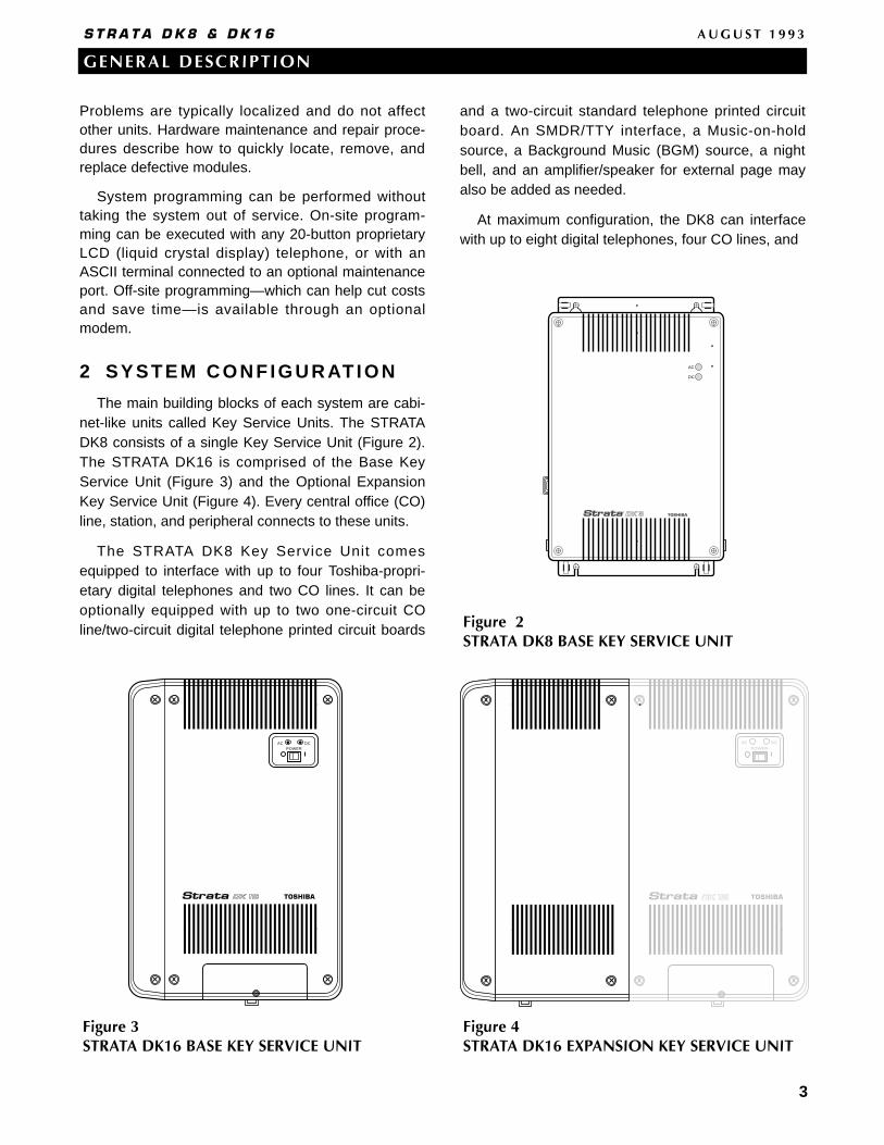
Problems are typically localized and do not affectother units. Hardware maintenance and repair proce-dures describe how to quickly locate, remove, andreplace defective modules.
System programming can be performed withouttaking the system out of service. On-site program-ming can be executed with any 20-button proprietaryLCD (liquid crystal display) telephone, or with anASCII terminal connected to an optional maintenanceport. Off-site programming—which can help cut costsand save time—is available through an optionalmodem.
2 SYSTEM CONFIGURATION
The main building blocks of each system are cabi-net-like units called Key Service Units. The STRATADK8 consists of a single Key Service Unit (Figure 2).The STRATA DK16 is comprised of the Base KeyService Unit (Figure 3) and the Optional ExpansionKey Service Unit (Figure 4). Every central office (CO)line, station, and peripheral connects to these units.
The STRATA DK8 Key Service Unit comesequipped to interface with up to four Toshiba-propri-etary digital telephones and two CO lines. It can beoptionally equipped with up to two one-circuit COline/two-circuit digital telephone printed circuit boards
and a two-circuit standard telephone printed circuitboard. An SMDR/TTY interface, a Music-on-holdsource, a Background Music (BGM) source, a nightbell, and an amplifier/speaker for external page mayalso be added as needed.
At maximum configuration, the DK8 can interfacewith up to eight digital telephones, four CO lines, and
AC DCPOWER
AC
DC
Figure 2STRATA DK8 BASE KEY SERVICE UNIT
Figure 4STRATA DK16 EXPANSION KEY SERVICE UNIT
AC DCPOWER
Figure 3STRATA DK16 BASE KEY SERVICE UNIT

two standard telephone devices. Note that while theDK8 provides up to ten station ports, only eight cansupport digital telephones. The last two standard sta-tion ports are designed for peripheral devices or stan-dard telephone interfaces.
The STRATA DK16 Base Key Service Unit comesequipped to interface with up to eight Toshiba-proprietary digital telephones and four CO lines. It canoptionally be equipped with a four-circuit standardtelephone printed circuit board, a Music-on-holdsource, a BGM source, a night bell, and anamplifier/speaker for external page.
The optional STRATA DK16 Expansion Key Ser-vice Unit can be attached to the standard unit toincrease system capacities. A system equipped withthe optional unit can support up to eight CO lines and16 Toshiba-proprietary telephones by using up tothree additional PCBs. An SMDR/TTY interface mayalso be added as needed. Note that while the DK16provides up to 20 station ports, only 16 can be digital
telephones, with the last four standard station portsdesigned for peripheral device or standard telephoneinterface.
Maximum capacities for STRATA DK8 and DK16systems are shown in Figures 5 and 6.
3 SYSTEM COMPONENTS
This section describes the components of theSTRATA DK8 Key Service Unit and the STRATADK16 Base and Expansion Key Service Units. Thefunctional block diagrams in Figures 7 and 8 illustratethe organization and connection of these compo-nents.
STRATA DK8 KEY SERVICE UNIT
In addition to the +5 volt converter, main processorand operating software for the system, the Key Ser-vice Unit contains the circuitry and components (Fig-ure 9 and Table E) as described in the following
4
GENERAL DESCRIPTION
S T R A T A D K 8 & D K 1 6 A U G U S T 1 9 9 3
Figure 5STRATA DK8 MAXIMUM CONFIGURATION
STANDARDTELEPHONESCO LINES
DIGITALTELEPHONES
BASICKEY SERVICE UNIT
EXPANDEDKEY SERVICE UNIT
2
4
4
8
0
2
BASEKEY SERVICE UNIT
STANDARDTELEPHONES
WITH EXPANSIONKEY SERVICE UNIT
CO LINES
4
888
DIGITALTELEPHONES
8
8168
ELECTRONICTELEPHONES
0
800
4
4412
Figure 6STRATA DK16 MAXIMUM CONFIGURATION
paragraphs. The weight and dimensions of the unit,which is designed for wall mounting, are as follows:
Height: 16.4 in (416 mm)Width: 10.0 in (254 mm)Depth: 3.0 in (76 mm)Weight: 5.7 lbs (2.59 kg)
Digital Telephone Circuits: The main circuit boardhas four integrated circuits that can connect to digi-tal telephones, stand-alone data interface units(PDIU-DSs), and a digital door phone/lock controlunit (DDCB). Furthermore, each of the digital tele-phones can support an integrated data interfaceunit (PDIU-DI) or an add-on module (ADM).
CO Line Circuits: Two circuits for loop start centraloffice (CO) lines are built into the main circuitboard. Each line can be programmed for Dual-toneMulti-frequency (DTMF) or dial pulse signaling andhas a switch to control potential excess volumethat could be created by a nearby private branchexchange (PBX) or CO. Built-in gas tubes help pro-tect each circuit from lightning.
Power Supply: The power supply generates+24VDC for the entire system, even in its expand-ed configuration.
Reserve Power: One or two optional Reserve PowerBattery and Chargers (HPFBs) can be connectedto the STRATA DK8 power supply to maintain nor-mal operation during a power failure (See Table Gfor reserve power time.)
Power Failure Interface: The Key Service Unit pro-vides an interface for a dedicated backup standardtelephone during a power failure. If the systempower fails, the backup telephone will automaticallyconnect to the CO1 line. This feature is indepen-dent of the HPFB.
Music-on-Hold Interface: Customers can connecttheir own Music-on-hold source to this interface.The source can also feed external page speakersand telephone speakers with Background Music.
Paging Interface: This 600-ohm interface can sup-port a Toshiba external speaker (HESB) or a cus-tomer-supplied amplifier and speaker for Paging,night ringing, and Background Music applications.
Flexible Relay Contact: A relay contact can be pro-grammed to either mute Background Music during
a page announcement over external speakers, tooperate a device–such as an answering machineor ringing bell–during the Night Mode, or to provideon-off control for a Music-on-hold source.
Conference Interface (QCNU): The standard, facto-ry-installed QCNU provides two conference circuitswhich provide for simultaneous conversationbetween stations and/or CO lines connected to theDK8. The first conference circuit allows simultane-ous conversation between four parties; the secondcircuit supports three parties.
STRATA DK8 OPTIONAL PCBS
Auto Attendant Feature Key (QKYS1): The QKYS1plugs into the QRCU2A (not QRCU1) card toenable support of Built-in Auto Attendant.
CO Line/Digital Telephone Interface Unit (QCDU):The QCDU provides one CO line circuit and twodigital telephone circuits.
The CO line circuit offers all of the features that theKey Service Unit CO line circuits provide, and thedigital telephone circuits can support every periph-eral (except DDCB) that the Key Service Unit digi-tal circuits can support. Up to two QCDU units maybe installed.
Standard Telephone Interface Unit (QSTU): Theoptional QSTU provides two circuits that can inter-face with 500- and 2500-type standard telephones,as well as the other single-line devices listedbelow. These devices may require that the optionalQRCU be installed in the Base Key Service Unit tointerpret the Dual-tone Multi-frequency (DTMF) sig-nals they may transmit.• Fax Machines• Modem• Dictation Equipment• Off-premises Stations• Voice Mail Devices• Auto Attendant Devices• Auto Attendant Digital Announcers
DTMF/ABR Tone Detection Receiver (QRCU): Sta-tion users in systems that have the optional QRCUinstalled can access Automatic Busy Redial (ABR)and communicate with devices, such as standardtelephones or voice mail machines, that requireDual-tone Multi-frequency (DTMF) signaling. Thisunit is also required for Direct Inward System
5
GENERAL DESCRIPTION
S T R A T A D K 8 & D K 1 6 A U G U S T 1 9 9 3
GENERAL DESCRIPTION
S T R A T A D K 8 & D K 1 6 A U G U S T 1 9 9 3
6
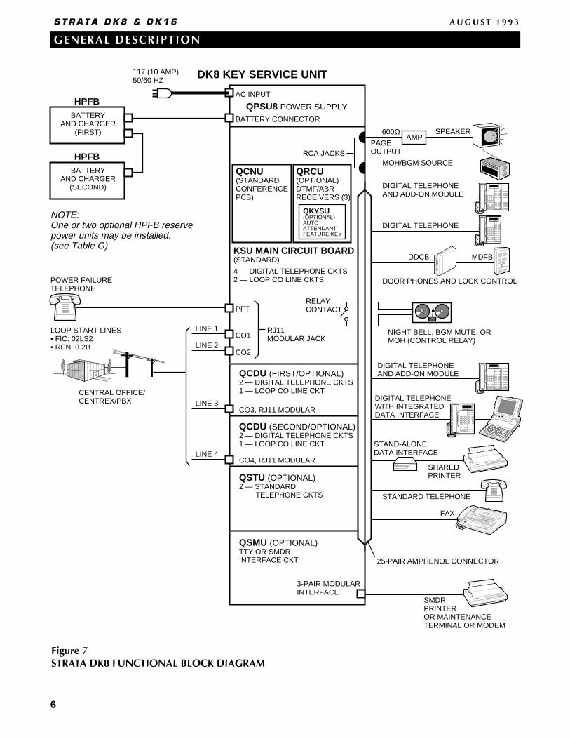
Figure 7STRATA DK8 FUNCTIONAL BLOCK DIAGRAM
SMDRPRINTEROR MAINTENANCETERMINAL OR MODEM
TOSHIBA
STANDARD TELEPHONE
STAND-ALONEDATA INTERFACE
SHAREDPRINTER
DIUPOWER READY CONNECT
TOSHIBA
DIGITAL TELEPHONEAND ADD-ON MODULE
DIGITAL TELEPHONEAND ADD-ON MODULE
MOH/BGM SOURCE
DDCB MDFB
AMP
DIGITAL TELEPHONE
SPEAKER
DOOR PHONES AND LOCK CONTROL
600Ω
NIGHT BELL, BGM MUTE, ORMOH (CONTROL RELAY)
DK8 KEY SERVICE UNIT
AC INPUT
QCNU(STANDARDCONFERENCEPCB)
BATTERY CONNECTOR
117 (10 AMP)50/60 HZ
HPFBBATTERY
AND CHARGER(FIRST)
HPFBBATTERY
AND CHARGER(SECOND)
NOTE:One or two optional HPFB reserve power units may be installed. (see Table G)
POWER FAILURETELEPHONE
LOOP START LINES• FIC: 02LS2• REN: 0.2B
CENTRAL OFFICE/CENTREX/PBX
LINE 1 LINE 2
CO1
PFT
CO2
RJ11MODULAR JACK
QCDU (FIRST/OPTIONAL)2 — DIGITAL TELEPHONE CKTS1 — LOOP CO LINE CKT
CO3, RJ11 MODULAR
CO4, RJ11 MODULAR
QCDU (SECOND/OPTIONAL)2 — DIGITAL TELEPHONE CKTS1 — LOOP CO LINE CKT
LINE 3
LINE 4
QSTU (OPTIONAL)2 — STANDARD TELEPHONE CKTS
QSMU (OPTIONAL)TTY OR SMDRINTERFACE CKT
3-PAIR MODULARINTERFACE
FAX
TOSHIBA
DIGITAL TELEPHONEWITH INTEGRATEDDATA INTERFACE
PAGEOUTPUT
RELAYCONTACT
25-PAIR AMPHENOL CONNECTOR
QPSU8 POWER SUPPLY
QRCU(OPTIONAL)DTMF/ABRRECEIVERS (3)
KSU MAIN CIRCUIT BOARD(STANDARD)
4 — DIGITAL TELEPHONE CKTS2 — LOOP CO LINE CKTS
RCA JACKS
QKYSU(OPTIONAL)AUTOATTENDANTFEATURE KEY

7
GENERAL DESCRIPTION
S T R A T A D K 8 & D K 1 6 A U G U S T 1 9 9 3
PAGE ZONE 4
BASE KEYSERVICE UNIT
EXPANSION KEYSERVICE UNIT
_ +
OPTIONAL CUSTOMERSUPPLIED BATTERIES(SEE TABLE G)
12 VOLTBATTERY
_ + PBTCCABLE
12 VOLTBATTERY
_ +
117 VAC(15 AMP)50/60 HZ
KPSU16DIGITAL TELEPHONEAND ADD-ON MODULE
CO4
25-PAIRAMPHENOL CONNECTOR
PIOUSORPIOU
CO3
CO2
CO1
DIGITAL TELEPHONE WITHINTEGRATEDDATA INTERFACE
LOOP START LINES• FIC: 02LS2• REN: 0.2B
CENTRAL OFFICE/CENTREX/PBX
POWER FAILURETELEPHONE (PFT)
MODULAR CONNECTORS
RCA JACKS
DOOR LOCK OR BGM MUTE CONTROL RELAY
ALARM RELAY SENSOR
NIGHT BELL OR MOH (CONTROL RELAYS)
SMDR PRINTER (SMDR PORT)
MOH/BGM SOURCE
VOICE MAIL
PERSONALCOMPUTER
MODEM
ALTERNATE BGM SOURCE
DDCB MDFB
MODULAR CONNECTORS RJ14C
PCOU(4)
KCDU(2/4)
RSSUTTY
Port only
CO LINE PCB
CO LINE/DIGITALSTATIONPCB
PERIPHERALINTERFACEPCB
AMP
CHARGER
BATT
AC INPUT BUILT-IN
DIGITALTELE-PHONECIRCUITS(8)
OPTIONALSTANDARDTELEPHONECIRCUITS(4)KSTU
DIGITAL TELEPHONEAND DSS CONSOLE
STANDARD TELEPHONE
SPEAKER
DOOR PHONES AND LOCK CONTROL
BUILT-INCO LINELOOPCIRCUITS(4)
OPTIONALDTMF/ABRRCVRS (4)K4RCU
OPTIONALFEATURECARTRIDGEKFCU
PDKU(8)
STATIONPCBs
DIGITAL
PEKU(8)
PESU(4/2)
PSTUOR
RSTU(8)
FAX
STAND-ALONEDATA INTERFACE
ELECTRONIC TELEPHONE
STANDARD TELEPHONE
PRINTER
600Ω
ELECTRONIC
ELECTRONIC/STANDARD
STANDARDTELEPHONE
CO 5 - 8LINES(4)
RJ11
DIUPOWER READY CONNECT
TOSHIBA
25-PAIRAMPHENOL CONNECTOR
NIGHT BELL, BGM MUTE, ORMOH (CONTROL RELAY)
DOOR PHONES AND LOCK CONTROL
DDCB MDFB
PIOU PAGE ZONE RELAY CONTROLPAGE ZONE 1•
•
•
MAINTENANCE TERMINAL (TTY PORT)
IMDU(MODEM)
See Table I
Figure 8STRATA DK16 FUNCTIONAL BLOCK DIAGRAM

GENERAL DESCRIPTION
S T R A T A D K 8 & D K 1 6 A U G U S T 1 9 9 3
8
Access (DISA) operation. Each QRCU card pro-vides three shared circuits.
IMPORTANT NOTE: The QRCU2 version of this circuit card isrequired for Built-in Attendant operation.
SMDR/TTY Interface Unit (QSMU): The optionalQSMU provides an interface for either SMDR out-put or TTY maintenance port. QSMU operation issoftware selectable (TTY or SMDR). A customer-supplied printer or Call Accounting device can beconnected to the QSMU for SMDR or a terminal(local maintenance) or modem (Remote Mainte-nance) can be connected to the QSMU for systemprogramming. Only one option (SMDR or TTY) canfunction at a time.
STRATA DK16 BASE KEY SERVICE UNIT
In addition to the main processor and operatingsoftware for the system, the Base Key Service Unitcontains the circuitry and components (Figure 10 andTable F) described as follows. The weight and dimen-sions of the unit, which is designed for wall mounting,are as follows
Height: 18.0 in (457 mm)
Width: 12.2 in (310 mm)
Depth: 3.4 in (86 mm)
Weight: 8.4 lbs (3.8 kg)
Digital Telephone Circuits: The main circuit boardhas eight integrated circuits that can connect todigital telephones, stand-alone data interface units(PDIU-DSs), one digital door phone/lock control
QCDU (optional)
QMAROM
QCNU
MOHJACK
600ΩPAGE
SW1
ON OFF
BATT
QSMU(optional)
WA
RN
ING
Haz
ardo
us v
olta
ge in
side
!If
serv
icin
g re
quire
d,re
mov
e A
.C. c
ord.
AC
DC
(standard)Conference
RESERVEBATTERYCONNECTOR
DC POWERON/OFF SWITCH
SMDR/TTY3-PAIRMODULAR JACK
QSMU, SMDR/TTYPCBCO4
CO2
CO1
CO3
PFT, RJ11MODULAR JACK
BATTERY JUMPER SW1, FORCUSTOMER DATA MEMORY
AC AND DCPOWERINDICATOR LEDs
QPSU8POWER SUPPLY
AC POWERCORD/PLUG 4' 7"
QRCU-3 CIRCUITDTMF AND ABRTONE DETECTORPCB (optional)
J6-25-PAIRAMPHENOL JACKFOR TELEPHONETIP/RING ANDRELAY CONTACT(FEMALE)
MUSIC-ON HOLD RCA JACK VR701 MOH VOLUMECONTROLPAGING OUTPUT RCA JACK
MAIN CIRCUIT BOARD
1-CO line CKT (4)2-Digital 2-Telephone CKT
QCDU (optional)
1-CO line CKT (3)2-Digital 2-Telephone CKT
MODULARRJ11 JACKS
2-StandardTelephone
Circuits
QSTU(QSTS)
(optional)
Figure 9STRATA DK8 KEY SERVICE UNIT INTERIOR (CONNECTORS AND INTERFACES)
GENERAL DESCRIPTION
S T R A T A D K 8 & D K 1 6 A U G U S T 1 9 9 3
9
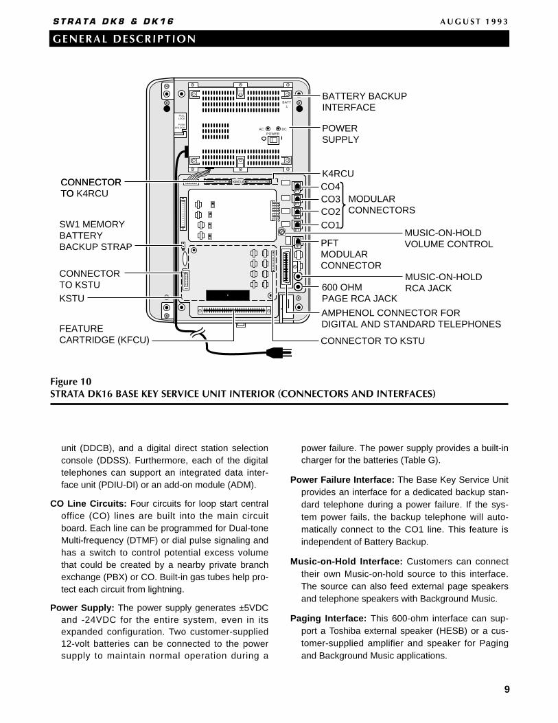
unit (DDCB), and a digital direct station selectionconsole (DDSS). Furthermore, each of the digitaltelephones can support an integrated data inter-face unit (PDIU-DI) or an add-on module (ADM).
CO Line Circuits: Four circuits for loop start centraloffice (CO) lines are built into the main circuitboard. Each line can be programmed for Dual-toneMulti-frequency (DTMF) or dial pulse signaling andhas a switch to control potential excess volumethat could be created by a nearby private branchexchange (PBX) or CO. Built-in gas tubes help pro-tect each circuit from lightning.
Power Supply: The power supply generates ±5VDCand -24VDC for the entire system, even in itsexpanded configuration. Two customer-supplied12-volt batteries can be connected to the powersupply to maintain normal operation during a
power failure. The power supply provides a built-incharger for the batteries (Table G).
Power Failure Interface: The Base Key Service Unitprovides an interface for a dedicated backup stan-dard telephone during a power failure. If the sys-tem power fails, the backup telephone will auto-matically connect to the CO1 line. This feature isindependent of Battery Backup.
Music-on-Hold Interface: Customers can connecttheir own Music-on-hold source to this interface.The source can also feed external page speakersand telephone speakers with Background Music.
Paging Interface: This 600-ohm interface can sup-port a Toshiba external speaker (HESB) or a cus-tomer-supplied amplifier and speaker for Pagingand Background Music applications.
AC DCPOWER
CONNECTOR TO KSTU
POWER SUPPLY
SW1 MEMORYBATTERY BACKUP STRAP
CONNECTOR TO K4RCU
CONNECTOR TO KSTU
BATTERY BACKUPINTERFACE
CONNECTOR TO
BATT±
KRCU
PULLLOCK
PUSHUNLOCK
MUSIC-ON-HOLDVOLUME CONTROL
AMPHENOL CONNECTOR FORDIGITAL AND STANDARD TELEPHONES
MUSIC-ON-HOLD RCA JACK600 OHM
PAGE RCA JACK
CO4CO3CO2CO1
PFTMODULAR CONNECTOR
MODULARCONNECTORS
FEATURECARTRIDGE (KFCU)
K4RCU
KSTU
Figure 10STRATA DK16 BASE KEY SERVICE UNIT INTERIOR (CONNECTORS AND INTERFACES)
10
GENERAL DESCRIPTION
S T R A T A D K 8 & D K 1 6 A U G U S T 1 9 9 3
Flexible Relay Contacts: A pair of relay contacts canbe programmed to either mute Background Musicduring a page announcement over external speak-ers, to operate a device—such as an answeringmachine or ringing bell—during the Night Mode, orto provide on-off control for a Music-on-holdsource.
Standard Telephone Interface Unit (KSTU): Theoptional KSTU provides four circuits that can inter-face with 500- and 2500-type standard telephones,as well as the other single-line devices listed below.These devices may require that the optionalK4RCU be installed in the Base Key Service Unit tointerpret the Dual-tone Multi-frequency (DTMF) sig-nals they may transmit.
• Fax Machines
• Modem
• Dictation Equipment
• Alternate Background Music source
• Off-premises Stations
• Voice Mail Devices
• Auto Attendant Devices
DTMF/ABR Tone Detection Receiver (K4RCU): Sta-tion users in systems that have the optionalK4RCU installed can access Automatic Busy Redi-al (ABR); and, communicate with devices, such asstandard telephones or voice mail machines, thatrequire Dual-tone Multi-frequency (DTMF) signal-ing. This unit is also required for Direct Inward Sys-tem Access (DISA) operation, as well as for Built-inAuto Attendant operation. Each K4RCU card con-tains four shared receivers.
Feature Cartridge (KFCU): The optional plug-in fea-ture cartridge will allow for the integration of futurefeature upgrades. The KFCU1A version of this car-tridge is required for Built-in Auto Attendant opera-tion.
STRATA DK16EXPANSION KEY SERVICE UNIT
The optional Expansion Key Service Unit, whichattaches easily to the side of the Base Unit, offers fouruniversal slots (Figure 11), three of which can hostany of the printed circuit boards (PCBs) described inthe following paragraphs (Table H). The weight anddimensions of the unit are as follows:
Height: 18.0 in (457 mm)Width: 7.8 in (198 mm)Depth: 3.4 in (86 mm)Weight: 1 lb (.45 kg) when emptyWeight: 5.3 lbs (2.4 kg) when full
NOTE: No more than three Expansion Key Service Unitslots can be occupied at one time. The fourthslot is reserved for future use.
CO Line Interface Unit (PCOU): The PCOU has fourloop start CO line circuits that have the same char-acteristics as the CO circuits in the Base Key Ser-vice Unit.
Digital Telephone Interface Unit (PDKU): ThePDKU has eight digital telephone circuits that cansupport the same peripherals as the digital circuitsin the Base Key Service Unit.
Option Interface Unit (PIOU): The PIOU providesinterfaces for such useful features as external zonepaging, Station Message Detail Recording(SMDR), and a remote maintenance modem sub-assembly (IMDU). Additionally, it has relay contactsfor the control of a customer-provided door lock,Music-on-hold source, or other optional device (seeTable I). The PIOU card's three-watt or 600 Ω pag-ing output is not used since paging is supported bythe Base Key Service Unit paging interface.
Simplified Option Interface Unit (PIOUS): With theexception of the Zone Paging interface, the PIOUShas everything that the PIOU has, including theSMDR and IMDU interfaces (Table I).
Remote Maintenance Modem Subassembly(IMDU): The IMDU is an optional modem that joinsto a PIOU or PIOUS to provide the system with alink to off-site programming and maintenanceequipment, such as a personal computer or ASCIIterminal.
It has an internal maintenance channel and doesnot require a dedicated CO line or station port.Data transmission speed can be set at 300 or 1200BPS full duplex.
Remote/Local Maintenance Interface Unit(RSSU): Option TTY interface PCB used for con-necting a maintenance terminal or external modem(local or remote) to the DK16. Requires the DK16expansion cabinet.

Standard Telephone Interface Unit (PSTU): ThePSTU has eight standard telephone circuits whichcan interface with the same devices as the optionalKSTU in the Base Key Service Unit. A K4RCUinstalled in the Base Key Service Unit interpretsDTMF tones transmitted by devices connected tothe PSTU.
Standard Telephone Interface Unit (RSTU): TheRSTU has eight circuits that can support single-linedevices. Besides rotary and push-button standardtelephones, the RSTU can support fax machines,dictation equipment, modems, a separate Back-ground Music Source, off-premises stations, Toshi-ba VP (Voice Processing) systems, digitalannouncement devices for the optional Built-inAuto Attendant feature, and customer-supplied
voice mail devices. A K4RCU installed in the BaseKey Service Unit interprets DTMF tones transmit-ted by devices connected to the RSTU.
R48S: The optional R48S unit can be connected tothe RSTU to extend the loop length (resistancelevel) of standard telephone circuits from 600 ohmsto 1200 ohms. This allows standard telephones tobe connected at further distances from the DK16system.
Electronic Telephone Interface Unit (PEKU): ThePEKU provides eight electronic telephone circuitsthat can interface with electronic telephones, anAlternate Background Music (BGM) source, adirect station selection console (HDSS), an exter-
11
GENERAL DESCRIPTION
S T R A T A D K 8 & D K 1 6 A U G U S T 1 9 9 3
Figure 11STRATA DK16 EXPANSION KEY SERVICE UNIT INTERIOR
EXPANSION CARD SLOTS*
STRATA DK16EXPANSION UNIT
EXPANSION COVER
SIDE COVER
*NOTE: One slot is reserved for future use.
STRATA DK16BASE UNIT
GENERAL DESCRIPTION
S T R A T A D K 8 & D K 1 6 A U G U S T 1 9 9 3
12
nal amplifier for Direct Inward System Access(DISA) or two-CO line Conferencing.
Standard/Electronic Telephone Interface Unit(PESU): The PESU PCB offers two standard andfour electronic telephone circuits. Its standard cir-cuits support the same devices as the KSTU andPSTU, and its electronic circuits interface with thesame peripherals as the PEKU, except for theHDSS console. Standard DTMF telephone circuitoperation requires a K4RCU in the Base Key Ser-vice Unit.
Off-hook Call Announce Upgrade Unit (EOCU):Electronic telephones connected to PEKU andPESU PCBs can receive Off-hook CallAnnounce—intercom calls over their speaker whilethey are on another call—if the PCBs are equippedwith an EOCU. Digital telephones also support thisfunction but do not require an EOCU type PCB inthe KSU.
CO Line/Digital Telephone Interface Unit (KCDU):The KCDU provides two CO line circuits and fourdigital telephone circuits. The CO line circuits offerall of the features that the Base Key Service Unitand the PCOU line circuits provide. The digital tele-phone circuits can support every peripheral (exceptfor the DDSS console) that the PDKU and a BaseKey Service Unit digital circuit can support.
TOSHIBA PERIPHERALS
Toshiba offers a number of peripherals that can beconnected to the STRATA DK8 and DK16 systems.Tables K and L contain the capacity and interface ofeach peripheral, including customer-supplied periph-erals.
Digital Telephones: The STRATA 2000-series digitaltelephones possess the most up-to-date callingand messaging features. Each telephone has anattractive design and is available in either charcoalgray or ash white. The STRATA DK8 can supportup to eight of the 2000-series digital telephones;the STRATA DK16 can support as many as 16.There are four models in this series—theDKT2010-H (Figure 12), DKT2010-SD (Figure 13),DKT2020-S (Figure 14), and the DKT2020-SD
(Figure 15)—each of which provides some or all ofthe features described below.• Liquid Crystal Display (LCD)—Available with
the DKT2010-SD and the DKT2020-SD, LCDsdisplay a variety of calling and messaginginformation. LCD telephone users can accessthe following features and more: § Feature Prompting Soft Keys§ Alphanumeric Messaging§ Busy Lamp Field (BLF) Indication§ Central Office (CO) Line Identification§ Timed Reminders with Messaging§ Intercom User Name/Number Display§ Called Number Display§ Call Duration Display§ Date/Time of Day Display
• Speakerphone—DKT2010-SD, DKT2020-S, andDKT2020-SD users can each receive andmake outside calls without lifting the handset.
• Handsfree Answerback—DKT2010-H userscan answer intercom calls from the telephoneset speaker without lifting the handset.
• Flexible Buttons—Each model has flexiblebuttons which can be assigned as feature but-tons, eliminating the need to dial accesscodes. The DKT2010-H and the DKT2010-SDboth have 10 flexible buttons, and theDKT2020-S and DKT2020-SD have 20 flexiblebuttons.
• Fixed Buttons—Fixed buttons, which are per-manently assigned to all of the models, provideaccess to frequently-used features, such asHold and Redial.
Digital Telephone Upgrade Options: Digital tele-phones may be upgraded for the following options.• Integrated Data Interface Unit (PDIU-DI2):
Users of digital telephones equipped with aPDIU-DI2 (Figure 16) connected to a personalcomputer (PC) or ASCII terminal can makedata calls to printers, personal computers, andother data devices, as well as both internal andexternal voice calls.
• Add-on Module (ADM): An ADM (Figure 21)can be connected to a 2000-series digital tele-phone to provide 20 Direct Station Selectionbuttons for STRATA DK16; and 10 Direct Sta-tion Selection buttons, eight personal SpeedDial buttons, one Night Transfer button, andone All Call Page button for STRATA DK8.

• Off-hook Call Announce (DVSU): DVSU-equipped digital telephones can receive Off-hook Call Announce. Every digital telephonecan have this upgrade, which allows stations toreceive intercom calls over their speaker whileon another call. No extra wires to the tele-phone are required.
• Loud Ringing Bell/Headset Interface(HHEU): The HHEU provides interfaces forboth a headset and a Loud Ringing Bellspeaker. With Loud Ringing Bell, the speakercircuitry amplif ies the ringing or voiceannouncement of an incoming call.
Toshiba VP Voice Messaging Systems: Toshiba VPVoice Messaging Systems, which provide a widearray of useful and progressive features, are com-patible with both STRATA DK8 and DK16 systems.
Stand-alone Data Interface Unit (PDIU-DS): PDIU-DSs (Figure 17) enable users to make switcheddata connections for modem pooling, printer shar-ing, and host/mainframe computer accessing.LEDs on the front panel of the PDIU-DS indicatethe status of each call.
Door Phone/Lock Control Unit (DDCB): Doorphones (MDFBs) (Figure 18) can serve a variety of
13
GENERAL DESCRIPTION
S T R A T A D K 8 & D K 1 6 A U G U S T 1 9 9 3
Figure 1210-BUTTON DIGITAL TELEPHONE WITHHANDSFREE ANSWERBACK (DKT2010-H)
Figure 1310-BUTTON DIGITAL SPEAKERPHONE WITHLIQUID CRYSTAL DISPLAY (DKT2010-SD)
Figure 1420-BUTTON DIGITAL SPEAKERPHONE(DKT2020-S)
Figure 1520-BUTTON DIGITAL SPEAKERPHONE WITHLIQUID CRYSTAL DISPLAY (DKT2020-SD)
white phone
GENERAL DESCRIPTION
S T R A T A D K 8 & D K 1 6 A U G U S T 1 9 9 3
14
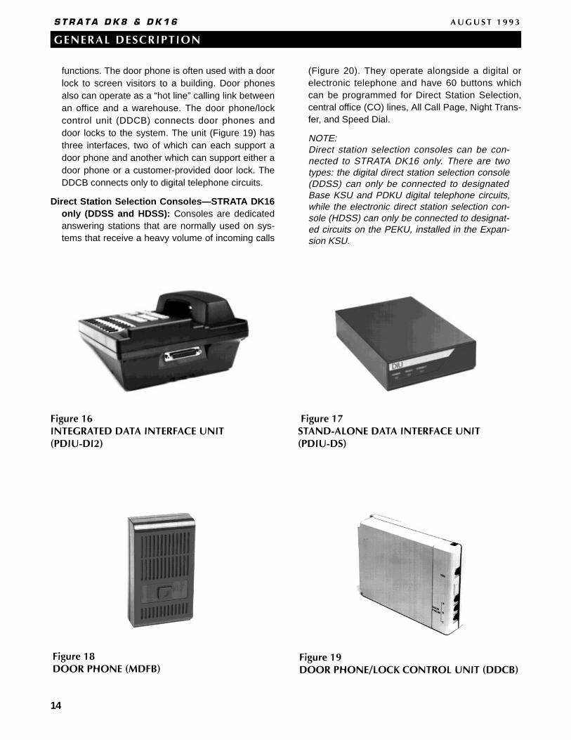
Figure 16INTEGRATED DATA INTERFACE UNIT(PDIU-DI2)
Figure 17STAND-ALONE DATA INTERFACE UNIT(PDIU-DS)
functions. The door phone is often used with a doorlock to screen visitors to a building. Door phonesalso can operate as a “hot line” calling link betweenan office and a warehouse. The door phone/lockcontrol unit (DDCB) connects door phones anddoor locks to the system. The unit (Figure 19) hasthree interfaces, two of which can each support adoor phone and another which can support either adoor phone or a customer-provided door lock. TheDDCB connects only to digital telephone circuits.
Direct Station Selection Consoles—STRATA DK16only (DDSS and HDSS): Consoles are dedicatedanswering stations that are normally used on sys-tems that receive a heavy volume of incoming calls
(Figure 20). They operate alongside a digital orelectronic telephone and have 60 buttons whichcan be programmed for Direct Station Selection,central office (CO) lines, All Call Page, Night Trans-fer, and Speed Dial.
NOTE:Direct station selection consoles can be con-nected to STRATA DK16 only. There are twotypes: the digital direct station selection console(DDSS) can only be connected to designatedBase KSU and PDKU digital telephone circuits,while the electronic direct station selection con-sole (HDSS) can only be connected to designat-ed circuits on the PEKU, installed in the Expan-sion KSU.
Figure 18DOOR PHONE (MDFB)
Figure 19DOOR PHONE/LOCK CONTROL UNIT (DDCB)

GENERAL DESCRIPTION
S T R A T A D K 8 & D K 1 6 A U G U S T 1 9 9 3
15
Electronic Telephone (STRATA DK16 only): Usersmigrating upwards from older Strata systems cancarry forward up to eight of their electronic tele-phones to use on a Strata DK16 with expansioncabinet. Most of the features available on the digitaltelephone are also available on the electronic ver-sion; the most important exceptions are the lack ofhandset adjustable prompting, and LCD largercharacter size.
External Speaker: The HESB is a multifunctional,external 6-inch, 3-watt amplified speaker unit. Itcan be used as a paging speaker, an amplified talk-back speaker, or a Loud Ringing Bell.
CUSTOMER-SUPPLIED PERIPHERALS
The STRATA DK8 and DK16 support many cus-tomer-supplied peripheral devices, several of whichare listed below:• Voice Mail/Auto Attendant Device • Dictation Equipment • External Maintenance Modem• Fax Machine• Local Maintenance Terminal• Alternate BGM Source• Music-on-Hold/Background Music Source • External Page Equipment
CABLING AND CONNECTORS
STRATA DK8 and DK16 utilize industry standardcabling and connectors to interface with central office(CO) lines, stations, and peripherals.
Stations use standard twisted pair cabling to con-nect to the system via the main distribution frame(MDF). Digital and standard telephones require justone pair, whereas electronic telephones (STRATADK16 only) need two-pair (Table B).
Station printed circuit boards (PCBs) and circuitsconnect to stations and peripherals with a 25-pairamphenol connector via the MDF. CO line circuitsinterface with the public telephone network via modu-lar connectors.
4 SYSTEM FEATURES
This section describes features that are availableon a system-wide basis for both DK8 and DK16,except where otherwise noted (Table N).
Account Codes (Forced/Voluntary/Verified):Account Codes provide a method of tracking andcategorizing central office (CO) calls on the StationMessage Detail Recording (SMDR) report. Theymay be required before dialing calls (Forced) orcan be optionally entered during calls (Voluntary).Codes can be as long as 15 digits and be Verified
Figure 2120-BUTTON DIGITAL TELEPHONE WITH ADD-ON MODULE
Figure 2060-BUTTON DIRECT STATION SELECTIONCONSOLE (DDSS SHOWN)
white phone

16
GENERAL DESCRIPTION
S T R A T A D K 8 & D K 1 6 A U G U S T 1 9 9 3
(specific numbers) or Nonverified (nonspecificnumbers). A printout of each Account Code printsout on the SMDR report after each call.
NOTE:The 911 emergency number bypasses Forced Ver-ified Account Code requirements. In addition, twoother customer-assigned numbers (1 ~ 4 digits)may be programmed to bypass Forced VerifiedAccount Code requirements.
Alarm Sensor (DK16 only) : The optionalPIOU/PIOUS printed circuit board (PCB) has arelay that can be connected to a customer-suppliedalarm system. If the alarm system is tripped, therelay will cause the speakers of all electronic anddigital telephones to emit a loud alert tone. Thedigital or electronic telephone alarm tone is resetfrom any station programmed with a designatedbutton.
All Call Voice Page: A user can page all stationspeakers simultaneously. External speakers canalso be part of an All Call Voice Page.
Alternate Point Answer: Users can answer a trans-ferred central office (CO) line call from any stationthat also has the CO line.
Amplified Conference Interface (DK16 only): Thisunit provides an interface for a customer-suppliedamplifier. The amplifier is shared by all CO linesand will be automatically connected to a two-COline or Direct Inward System Access (DISA) call toprovide a louder sound level on these types ofcalls. To support an Amplified Conference Inter-face, a PEKU or PESU is required in the expansionunit. A maximum of one amplifier per system canbe connected. The amplifier is automaticallyswitched into 2-CO line DISA or conference callson a first call basis (only one amplified call at atime).
Auto Attendant (Built-in): The optional Built-in AutoAttendant feature operates like an automaticstation attendant or switchboard operator thatquickly and efficiently distributes calls to stationsselected by callers. With 24-hour coverage, AutoAttendant can process a large volume of calls,freeing employees to perform other tasks. Incom-ing callers will hear a menu of dialing prompts,such as “Dial 3 for Sales; dial 4 for Customer Ser-
vice” (up to 10 selections are available). After thecaller dials the digit, he/she will be routed to a sta-tion that has been assigned via system program-ming to the selected digit. Built-in Auto Attendantutilizes a standard telephone port. Additional sup-portive hardware requirements for DK8 systemsinclude the DTMF/ABR Tone Detection Receiver(QRCU2 only) and the Auto Attendant Feature Key(QKYS1). DK16 systems require the DK16DTMF/ABR Tone Detection Receiver (K4RCU) anda plug-in Feature Cartridge (KFCU1A).
Automatic Hold: Automatic Hold enables a user toplace an outside call appearing on a CO line buttonon hold simply by pressing another CO line orintercom button. The user can then alternatebetween the new and the old call simply by press-ing the desired button. If this feature is not activat-ed, users need to press the Hold button beforeaccessing another line and switching betweencalls. This feature is optionally programmable foreach telephone set.
Automatic Hold/Park Recall: Held calls can be pro-grammed to ring back, after a designated time, thestation that placed them on-hold. The recall time ofeach station can have an individual time set inde-pendently in programming for this feature, whichhelps ensure that held calls are always retrieved.
Automatic Release from Hold/DISA: The systemcan automatically disconnect a central office (CO)line on which a held party hangs up. This alsoapplies to Direct Inward System Access (DISA)calls and voice mail calls. Automatic Release isavailable on a CO-by-CO-line basis and operatesonly with COs that provide a disconnect signal.
Automatic Station Relocation: System users canrelocate their stations and maintain the intercomnumbers and features of their telephones, withouthaving to reprogram their system.
Background Music (BGM): BGM can be sent to tele-phone speakers and external speakers. The BGMsource can be applied flexibly. One music sourcecan feed both types of speakers, or, in DK16 only,each can have its own source. The music sourceused for Music-on-hold can also be piped to tele-phone speakers. An alternate BGM source can beconnected to a QSTU in DK8, or a KSTU, PESU,PEKU, PSTU, or RSTU in DK16.
Busy Station Transfer/Ringing: When a station orexternal auto attendant device programmed forthis feature transfers a call to a busy digital orelectronic telephone with this feature, the transfer-ring station or auto attendant device will receive aringing signal (instead of a busy tone) and thecalled busy station will receive a distinct call wait-ing tone and LED indication. At this point, thetransferring station or auto attendant device willnormally release and the call will camp-on thebusy station, providing a distinctive camp-on toneand CO line LED flash. The busy station can thenanswer the transferred call after it releases, trans-fers, or places its current call on hold. WithoutBusy Station Transfer/Ringing, stations and autoattendant devices will receive busy tone when try-ing to transfer calls to busy stations. Some autoattendant devices cannot transfer calls afterreceiving busy tone, and the transferred calls arerouted back to them.
Centrex/PBX Compatible: All system features arecompatible with Centrex/PBX operation; includingrepeat of Centrex/PBX ringing cadence, one-but-ton access to Centrex/PBX features, 1 ~ 4-digitstation numbering plan, and delayed ringing toselected stations.
Centrex Ringing Repeat: The system mimicsCO/Centrex/PBX cadences received from outsidelines when it rings a called station. This capabilityenables STRATA DK8 and DK16 to use specialCO/Centrex/PBX calling/callback features.
CO Line Groups: For easy access, various types ofCO lines can be assigned to groups (normally forpooled line and Least Cost Routing (LCR) applica-tions). All local lines, for example, can be assignedto one group and WATS lines in another group.Station users can access line groups with a dialingcode or by pressing a feature button. Up to fourCO line groups for DK8 and up to eight CO linegroups for DK16 can be created.
CO Line Queuing: A station user can use the Auto-matic Callback feature to queue up for a busy out-going CO line. When the CO line finally becomesavailable, the system calls the station back. Queu-ing applies to single CO lines, CO line groups, andwhen calling via LCR.
Conferencing: A variety of Conferencing combina-tions are available to all station users, as listedbelow. Stations and central office (CO) lines can beadded in any order.• One or two stations and two CO lines• Two or three stations and one CO line• Four stations
Credit Card Calling: Callers can make credit cardcalls (0+ telephone number + credit card number)that bypass Toll Restriction. The calls are billed tothe credit card, not the STRATA DK8 and DK16central office (CO) line. The system requires that aspecific quantity of digits are dialed for this call;otherwise, the call will be dropped within 20 sec-onds to prevent operator-placed calls that would bebilled to the CO line.
Data Calling: STRATA DK8 and DK16 offers asophisticated optional data switching capability thatcan interconnect a wide range of customer-sup-plied data equipment, including personal comput-ers (PCs), printers, and modems. Asynchronousdata can be transmitted at speeds up to 19.2 kbps(see Table M). The system provides four datasecurity groups to restrict data calls betweengroups. Dialing by personal computer (both dataand voice calls) as well as modem pooling andprinter sharing is supported.
DAY/NIGHT Modes: The system has three availablemodes: DAY, DAY2, and NIGHT. Each mode canbe assigned a distinct CO-to-station, CO-to DISA,and CO-to-Remote Maintenance channel ringingarrangement. The system can be programmed witheither two or three modes (which can be changedby any station programmed with a Night Transferbutton):
Two modes: Three modes:DAY DAY
NIGHT DAY2NIGHT
Delayed Ringing: If a central office (CO) line callrings a station and is unanswered, alternate sta-tions can be programmed to ring 12 or 24 secondslater. The stations that were ringing initially willcontinue after the Delayed Ringing begins. Thisfeature is assigned on a line-by-line basis.
Direct Inward System Access (DISA): Outsidecallers using a Dual-tone Multi-frequency (DTMF)
17
GENERAL DESCRIPTION
S T R A T A D K 8 & D K 1 6 A U G U S T 1 9 9 3

GENERAL DESCRIPTION
S T R A T A D K 8 & D K 1 6 A U G U S T 1 9 9 3
18
telephone can dial internal stations or outgoingcentral office (CO) lines directly, without goingthrough a receptionist or operator. A security codecan be assigned to prevent undesired access toCO lines. DISA is available to any number of COlines.
Distinctive CO Line/Intercom Ringing: The incom-ing Central Office (CO) line ringing pattern for bothdigital and electronic telephones differs from theintercom ringing pattern, thereby helping to indi-cate the nature of a call. This feature is optional forstandard telephones.
Door Lock Control: Any telephone programmed witha door unlock button can unlock a customer-sup-plied electronic door lock just by pressing the but-ton. The DK8 can support as many as two unlockbuttons, and the DK16 can support up to three.Each unlock button can have an associated buttonon designated digital and electronic telephones.(The DDCB, PIOU, and PIOUS can each supportdoor lock control.)
Door Phones (MDFB): A door phone is frequentlymounted near a building entrance and is associat-ed with a customer-provided door lock to helpscreen visitors. However, a door phone can alsoserve other functions: it can operate as a soundmonitor (station users can call the door phone andlisten to the surrounding area) or as a “hot line”link. STRATA DK8 and DK16 can each support asmany as six door phones. Each door phone mustbe connected to a door phone/lock control unit(DDCB).
DTMF and Dial Pulse CO Line Compatible: DK8and DK16 systems work with both Dual-tone Multi-frequency (DTMF) and rotary dial pulse centraloffice (CO) lines.
DTMF Back Tone: DK8 and DK16 systems can beprogrammed to allow or prevent Dual-tone Multi-frequency (DTMF) tones from being returned to adigital or electronic telephone when a user dialsover central office (CO) lines or sends digits to avoice mail device.
DTMF Signal Time (80/160 milliseconds): Theduration of Dual-tone Multi-frequency (DTMF)tones that are sent via Speed Dial to CO lines andvia automatic dialing to voice mail devices can be
set at 80 or 160 milliseconds. The time can be setindependently for CO line outdialing and for voicemail automatic dialing.
Dual FCC Registration: DK8 and DK16 systems canbe configured for either key or hybrid operation.Separate FCC registration numbers apply to eachoperation type. The appropriate configuration foran individual system depends on its function. Formore details, refer to General End User Informa-tion, located in the front of this document.
External Page: Station users can make anannouncement over an external paging deviceconsisting of an amplifier and speaker, by enteringa brief access code. The paging device connectsdirectly to a 600 ohm output that is standard on theDK8 and DK16 Key Service Unit. The 600 ohmoutput is two-way and supports talk back amplifierapplications. For STRATA DK16, paging zoneoptions are also provided by the optional PIOUPCB in the Expansion Unit.
External Page Zones (DK16 only): The system cansupport as many as four external page zones. Sta-tion users can access just one page zone or all ofthem simultaneously simply by entering a briefaccess code. Zones may be composed of cus-tomer-supplied speaker(s) and amplifier(s) whichinterface with a PIOU printed circuit board in theExpansion Key Service Unit.
Flexible Button Assignment: Digital and electronictelephones have 10 or 20 buttons which may beflexibly programmed to access CO lines and fea-tures.
Flexible Intercom Numbering: A station intercomnumber can have as many as four digits, whereasit is normally two digits. The numbers can beassigned to any station port, and can be pro-grammed in any sequence. Single-digit intercomnumbers, such as 0, can be assigned to anattendant station.
Flexible Line Ringing Assignment: Each centraloffice (CO) line can be programmed to ring (or notring) any station in the system. A different ringingassignment scheme may be created for each ofthe three ringing modes—DAY, DAY2, or NIGHT.Stations assigned to ring can do so with any of thefollowing three timing designations:

19
GENERAL DESCRIPTION
S T R A T A D K 8 & D K 1 6 A U G U S T 1 9 9 3
• Immediate: Stations assigned IMMEDIATEtiming ring as soon as the CO line rings intothe system.
• Delay 1: If stations with IMMEDIATE timinghave not answered within 12 seconds, stationsassigned DELAY 1 timing begin ringing also.
• Delay 2: If stations have not answered within24 seconds, stations assigned DELAY 2 timingbegin ringing also.
Group Paging: Digital and electronic stations can bedivided into as many as four paging groups. Anystation user can make an announcement to one orall of these groups via station set speakers.
Least Cost Routing (LCR): Eight different plans maybe designed to automatically place outgoing callsover the most cost-efficient routes. Three differentLCR time schedules with their own priority sched-ules can be set up for the business day. Stationscan be grouped into one of four LCR classes, eachwith its own routing priority. Selected station usersmay have priority use of a line, even when theroute with the lowest cost is not available. LCR iscompatible with Automatic Busy Redial (ABR) andtwo-central office (CO) line Conference.
Live System Programming: Programming the sys-tem from an on-site or off-site location does notinterrupt service. Service is only interrupted forPCB additions or changes.
Memory Protection: If the power fails, the systemhas an internal battery backup that protects dataand the customer’s programmed configuration.This information will be maintained within a power-less system for at least six years.
Message Waiting: Any station and most voice maildevices can leave a message waiting indication onan LED of a digital or electronic station. The stationuser can retrieve the message simply by accessingthe intercom and pressing the button associatedwith the LED. A station can store up to four mes-sage waiting indications.
Modem Pooling: This feature allows many tele-phone users to share modems. One or more stan-dard, asynchronous type modem(s) that are com-patible with industry-type “AT” commands can beconnected to Stand-alone Data Interface Units(PDIU-DS) to form a modem pool. Users with digi-
tal telephones equipped with Data Interface Unitscan connect to the modems to place or receiveexternal data calls. The modems can be connectedto Strata DK standard telephone circuits and shareexternal CO lines or they can be connected to dedi-cated CO lines.
Music-on-hold: A customer-supplied radio tuner,compact disc player, or other device can be used tosend music or announcements to parties on-holdon central office (CO) or intercom lines.
Night Ringing Over External Page: Incoming centraloffice (CO) line or door phone calls can be pro-grammed to ring over an external speaker whenthe system is in the Night mode. The call can bepicked up from any telephone by entering a briefaccess code. After-hours employees who are notnear a ringing telephone are more likely to answercalls with this feature.
Night Ringing Over Selected Page Zones (DK16only): Central office (CO) l ines can be pro-grammed to night ring over selected PIOUpage zones via customer-supplied paging equip-ment. The lines can be divided into two groups(Tenant 1 and Tenant 2) which can then beassigned to night ring over the selected zones.
Non-blocking Talk Paths: All CO and intercom linescan be used at the same time. The system canoperate at full capacity at all times.
Off-premises Station: Off-site standard telephonescan be part of the system, capable of accessingSTRATA DK8 or DK16 features. Each off-site sta-tion requires a special line from the central office(OL13A or equivalent).
Outgoing Call Restriction: Stations can be selec-tively restricted from originating calls over any num-ber of CO lines. The same stations can receiveincoming calls over the restricted CO lines.
Pooled CO Line Buttons: Several central office (CO)lines can be pooled to appear under one digital orelectronic telephone CO line button. The lines canbe pooled in categories, e.g., WATS lines in onepool, regular lines in another.
Power Failure Transfer: A dedicated standard tele-phone can be connected to the DK8 Key ServiceUnit or DK16 Base Key Service Unit to provide

20
GENERAL DESCRIPTION
S T R A T A D K 8 & D K 1 6 A U G U S T 1 9 9 3
emergency service if the system power fails. Whilesystem power is present, the telephone is inopera-tive. However, if the system power fails, the stan-dard telephone will automatically connect to a des-ignated central office line (CO1), enabling accessto the public telephone network. When systempower is restored, the standard telephone willbecome inoperative again. Power failure transfer isindependent of reserve (battery) power.
Printer Sharing: This feature allows many users toshare one or more printers. Serial-type printers canbe connected to Stand-alone Data Interface Units(PDIU-DS) to allow users with digital telephonesequipped with Data Interface Units to connect (viaData Switching) to the printers. The printers can bealmost any type (laser, ink jet, dot matrix, etc.) butthey must have a serial interface as opposed to theparallel type.
Privacy/Non-privacy: Central office (CO) lines canbe private or non-private on a line-by-line basis.Private lines prohibit users from pressing a CO linebutton and accessing a line that is already in-use;users can do so on non-private lines. Private lineusers can change the mode with a privacy releasebutton, enabling as many as three stations to bepresent on a line.
Relay Service Options: The DK8 and DK16 KeyService units each contain relay contacts that canbe programmed to provide control functions forexternal equipment. The DK8 KSU and DK16 BaseKSU each have a single relay contact. This relaycontact can be programmed for one of three func-tions. The DK16 PIOUS and PIOU printed circuitboards (PCBs) each have two pairs of relay con-tacts. Each relay contact can be programmed forone of two functions. The PIOUS and PIOU relayoptions are independent and can be used simulta-neously with the DK16 Base Unit relay service toprovide multiple control functions.§ External Page Function: A page over external
speakers will mute Background Music that isbeing broadcast over the same speakers.
§ Door Lock Control Function (PIOUS andPIOU relays only): The relay will open a cus-tomer-supplied door lock for three or six sec-onds when a designated button is pressed onselected telephones.
§ Night Relay Function: An answering machineor a night bell (or chime) will be activated whena call rings in.
§ Hold Relay Function: A music-on-hold sourcewill turn on when a call is placed on-hold.
Remote Administration and Maintenance:System administration, programming, and mainte-nance can be performed from a personal computeror ASCII terminal at a remote location. In additionto the off-site equipment, the DK8 customer needsan external modem and optional QSMU PCB. TheDK16 customer needs to have the expansion unitequipped with an optional PIOU or PIOUS printedcircuit board and an IMDU piggy-back modem (orexternal modem) to access this feature. The use ofthis feature does not interrupt system operation.
Reserve Power (DK8): One or two optional ReservePower Battery and Chargers (HPFBs) can be con-nected to the system power supply as a power fail-ure backup. If there is a power failure, STRATADK8 automatically switches over to battery powerwithout any interruption in operation.
The built-in charger keeps the batteries chargedduring normal operation. Reserve power durationdepends on the condition of the batteries and thesystem load. (See Table G for reserve power time.)
Reserve Power (DK16): Two customer-supplied 12-volt batteries (gel-cell and maintenance free) canbe connected to the system power supply as apower failure backup. If there is a power failure,STRATA DK16 automatically switches over to bat-tery power without any interruption to operation. Astandard built-in charger circuit keeps the batteriescharged during normal system operation. Reservepower duration depends on the condition of thebatteries and the system load (see Table G forreserve power time).
Speed Dial: Speed Dial enables users to dial fre-quently called telephone numbers quickly by justdialing a two-digit access code or by pushing a fea-ture button. STRATA DK8, DK16, and Centrex/PBXfeature access codes can also be stored in SpeedDial. There are two types of Speed Dial:• System Speed Dial: A designated station can
create up to 40 Speed Dial numbers that areavailable to every station.
21
GENERAL DESCRIPTION
S T R A T A D K 8 & D K 1 6 A U G U S T 1 9 9 3
• Station Speed Dial: Each station user can cre-ate as many as 40 of his or her own personalSpeed Dial numbers.
Station Hunting: When a called station is busy, thecall (data or voice) will hunt to an assigned station.If the assigned station is busy, the call will hunt tothe next assigned station, and so on. The huntingsequence can be either consecutive or non-con-secutive, and is fully flexible. If a hunt station is callforwarded, calls to the station will ring at the for-warded destination—not the hunt destination. Thecall is eventually routed to the first idle station.Callers will receive busy tone if calling into a huntgroup of which all stations are busy.
Station Message Detail Recording (SMDR): Thesystem stores calling information that can be print-ed out with a printer or call accounting device con-nected to the optional QSMU PCB for STRATADK8, or the PIOU or PIOUS PCB for STRATADK16. The report includes time and length of call,as well as the called number. Customers can selectwhat type of calls—all calls, outgoing only, long dis-tance calls—they want to appear on the report.Account Code information can also be included.
System Programming through Any Station: Anyliquid crystal display 20-button digital (or electronictelephone for DK16) can be used to program thesystem. To prevent accidental entry, programmersmust dial an access code prior to entering the pro-gramming mode. (See Live System Programming.)
System Speed Dial: The system can store as manyas 40 Speed Dial numbers that can be accessedby all stations with either a two-digit access code ora flexible feature button. A designated stationassigns these numbers, which can be telephonenumbers, system feature access codes, or Cen-trex/PBX feature access codes.
Tandem CO Line Connections: This feature allowsup to two (DK8) or four (DK16) unattended line-to-line connections, freeing the originating station forother calls. For supervision purposes, the originat-ing station must have both CO line button appear-ances to allow tandem operation.
Tenant Service: Two small businesses in the sameoffice building can share a system. Tenants canhave separate Least Cost Routing and Toll Restric-tion plans, Night Transfer ringing assignments, and
flexible door phone and CO line ringing assign-ments.
Toll Restriction: Stations can be individually restrict-ed from making toll calls. Four restriction levels canbe defined, each allowing or denying specific areaand office codes, long distance information calls,international calls, and/or operator-assisted calls.Each station is assigned any one of the availablerestriction levels or no restriction. Individual COlines can be defined as unrestricted.
Toll Restriction Override by System SpeedDial: System Speed Dial numbers can be pro-grammed to override Toll Restriction. For instance,when employees need to access a toll number thatfalls into a restricted area/ office code for work pur-poses, an employer can program the particular tollnumber as a System Speed Dial number. Even iftheir stations are restricted, they can access thenumber with speed dialing.
Transfer Privacy: Optional transfer privacy can beprogrammed system-wide. When transfer privacy isprogrammed and an outside call is answered byone station, and then transferred to another station,the call can only be answered by the second sta-tion or by a station that has the Call Pickup feature.Other stations cannot pick up the transferred callwith a CO line button. (Refer to Alternate PointAnswer earlier in this section and Call Pickup in thenext section.)
Traveling Class of Service: The normal Toll Restric-tion class of a station can be temporarily changedto another class. Each of the four Toll Restrictionclasses can be assigned a four-digit code. If one ofthese codes is entered at a station, the station willassume the class associated with the code for thenext dialed number. The station will revert back toits normal Toll Restriction class for subsequentcalls. Traveling Class codes can be added, delet-ed, or changed by users only from stations select-ed in programming.
Unlimited Handsfree Intercom Paths: All intercomlines can carry handsfree conversations simultane-ously. Because intercom paths are non-blocking,the number is only limited by the amount of sta-tions.
Unrestricted Call Transfer over Intercom: Any COline call can be transferred to any station over theintercom line. A station does not need a specificCO line’s appearance in order to answer the call.

22
GENERAL DESCRIPTION
S T R A T A D K 8 & D K 1 6 A U G U S T 1 9 9 3
Voice Mail Interface: The system can be configuredwith a Toshiba VP Voice Messaging System or acustomer-supplied voice mail messaging system.The optional QSTU and QRCU PCB must beinstalled for voice mail operation for STRATA DK8.The KSTU and K4RCU must be installed for DK16.The following features are available with many sys-tems.• Automated Attendant: An integrated Auto-
mated Attendant can streamline the system’scall answering capability.
• Call Forward to Voice Mailbox: Each tele-phone user can forward calls directly to a per-sonal mailbox. The caller bypasses the usualsequence of voice mail commands and simplyleaves a message after hearing a tone.
• Message Waiting Indication: When a mes-sage is recorded in a user’s mailbox, the voicemail system automatically sets a messagewaiting indication—typically a flashing LED—atthe user's telephone.
• Voice Mail Control via Station: Station userscan control voice mail equipment from theirtelephone dialpads.
• Feature Integration: The integration of specialvoice mail features in STRATA DK system soft-ware enables the systems to work togethermore efficiently.
Voice or Tone Signaling: The system can be pro-grammed for either Voice Signaling or Tone Sig-naling as the standard method of intercom call sig-naling to a digital or electronic telephone. If ToneSignaling is selected, a station will ring whencalled. The called party will hear a tone burst andthen the caller’s voice if Voice Signaling is select-ed. A caller can always select the alternate methodimmediately after dialing the station number. ToneSignaling ensures privacy, while Voice Signalingenables quick communication.
5 TELEPHONE FEATURES
The following features are available toSTRATA DK8 and DK16 station users. All of thesefeatures are available with digital telephones, andmany with electronic and standard telephones (seeTable O).
Account Code Button: This button, which is avail-able with digital and electronic telephones, enablesusers to enter Voluntary Account Codes (Verifiedor Nonverified) during conversations without inter-rupting the talk path. It can also be used to enteran optionally required Verified Account Codebefore dialing a long distance call.
Add-on Module (ADM): Each 2000-series digitaltelephone can be connected to an ADM to provide20 Direct Station Selection buttons for STRATADK16; and 10 Direct Station Selection buttons,eight personal speed dial buttons, one night trans-fer button, and one all call page button for STRATADK8. The ADM connects to a host telephone; noadditional KSU station port is required.
Automatic Busy Redial (ABR): Digital and electronictelephone users that dial a busy outside telephonenumber can set ABR and have the number redi-aled automatically at preprogrammed intervals.The system will call back the station when it suc-cessfully dials the non-busy number. ABR is com-patible with Least Cost Routing. ABR requires theoptional QRCU (for STRATA DK8) or K4RCU (forSTRATA DK16).
Automatic Callback (ACB): Station users that callbusy stations can set ACB and have the systemcall them back when the busy station comes avail-able.
Automatic Hold/Park Recall: A CO line or intercomcall placed on hold or parked will automaticallyrecall the station at a preprogrammed elapsedtime. A different time period can be selected foreach station.
Automatic Line Selection: A digital or electronictelephone user with this feature will automaticallyaccess a CO line, CO line group, or the intercomwhenever its handset is lifted or its speaker buttonis pressed.
Automatic Park/Page: With the push of a button on adigital or electronic telephone, a central office (CO)line can be parked and an external pageannouncement delivered. Station users can pick upthe parked call after the page.
Background Music with Station Control: Digitaland electronic telephone users can control Back-

GENERAL DESCRIPTION
S T R A T A D K 8 & D K 1 6 A U G U S T 1 9 9 3
23
ground Music (BGM) playing over their telephonespeakers. The music may be switched on or offand the volume may be adjusted to suit the individ-ual user. A designated station can control (on/off)BGM over external page speakers.
Busy Override: Upon calling a busy station andreceiving a busy tone, a station user can dial a sin-gle-digit access code—or press a labeled featurebutton if calling from a properly configured digital orelectronic telephone—that sends a tone burst tothe called station. The busy station must be a digi-tal or electronic telephone to receive this tone.1000-series digital telephones and electronic tele-phones will receive the tone over their speaker,while 2000-series digital phones may optionallyreceive it over their handset or headset receiver aswell as the speaker.
Call Forward: Outside and intercom calls to stationsin the Call Forward mode are routed to an alternatestation or voice mail device. Stations in this modecan originate calls as usual. There are five CallForward modes, each described as follows:• All Calls: All calls to a busy or idle station set
with this mode will forward immediately, andthe station will not ring.
• Busy: All calls to a busy station set with thismode will forward immediately. When the sta-tion is idle, incoming calls will ring normally.
• No Answer: Calls to an idle station set withthis mode will ring for 12 seconds and then for-ward. When the station is busy, incoming callswill receive busy tone.
• Busy/No Answer: When a station is idle andin this mode, calls to it will ring for 12 secondsand then forward. When the station is busy,incoming calls will forward immediately.
• Fixed: Calls to an idle or busy digital or elec-tronic telephone in this mode will forwardimmediately to a destination assigned in sys-tem programming.
Call Park: A station can place (park) a call on-hold,make another call, and then return to the parkedcall. This feature can also be used to park an out-side central office (CO) line call and page a personinternally to pick up the call by dialing an accesscode.
Call Pickup: By going off-hook and dialing an accesscode, any station can pick up the following type ofcalls:• Calls on-hold or parked (selectively)• Calls ringing at other stations• An external page• CO line ringing at night over external page or
night bell• Door phone calls
Call Transfer with Camp-on: A station user cantransfer a call to a busy station, which will receivean alert tone indicating that a call is camped-on. Ifthe busy station fails to answer, the camped on callwill return to the station that transferred it.
Call Transfer Immediate: Transfers initiated with adesignated Feature Prompting Soft Key on digitaltelephones can transfer immediately after the finaldigit of the destination is dialed. If the called stationis not available or busy, the call will camp-on to it.This feature is a real aid for stations that have toprocess a large number of calls.
CO/Centrex/PBX Feature Buttons: System SpeedDial buttons on digital and electronic telephonescan be programmed with access codes, plus anyflashes or pauses necessary to access featuresthrough a host switching system.
Computer Auto Dialing: Voice and data calls can bedialed from the keyboard of a personal computerconnected to a digital telephone equipped with anintegrated data interface unit (PDIU-DI2). Standardcomputer dialing protocol is used, and calls can beinternal or external (no modem required).
Continuous DTMF Signal Time: The DTMF dial sig-nal sent to a central office (CO) line or voicemail/auto attendant device will last as long as a2000-series digital telephone user presses a buttonon the dialpad. This feature is not available withelectronic, standard, or 1000-series digital tele-phones; or, 2000-series digital telephone connect-ed to PDKU1 circuits.
Data Button: Digital telephones can have a data but-ton that allows manual dialing of internal data calls.
Direct Station Selection (DSS) Buttons: A digital orelectronic telephone user can ring a selected sta-tion by pressing a flexible feature button assignedwith DSS. The LED associated with the button pro-
24
GENERAL DESCRIPTION
S T R A T A D K 8 & D K 1 6 A U G U S T 1 9 9 3
vides the busy status of the station. Each flexiblebutton can be assigned as a DSS button to a differ-ent station.
Direct Station Selection Console Features(STRATA DK16 only): Digital and electronic tele-phones can operate with direct station selectionconsoles, which offer the following features:• Automatic Line Hold• Call Forward Override• Feature Buttons
§ All Call Voice Page§ CO line§ Direct Station Selection§ Night Transfer§ Speed Dial
• Voice or Tone Signaling
DISA Security Code Revision: Digital and electronictelephones selected in programming can revise theDirect Inward System Access (DISA) securitycode.
Distinctive LED Color Indications: Central office(CO) line LEDs illuminate as red or green to helpdigital telephone users determine the status ofcalls. Electronic telephone LEDs are always redwhen they light.
Distinctive LED Flash Indications: LEDs on digitaland electronic telephones will flash at varying ratesto indicate calling status.
Distinctive Station Ringing: Digital and electronictelephones can have one of two ring tones forincoming central office (CO) line calls. This helpsstation users identify if their own telephone is ring-ing.
Do Not Disturb (DND): Station users with digital andelectronic telephones can activate this feature toprevent intercom and transferred calls from ringingtheir telephones. Callers will hear a fast busy tone.To ensure that important calls are not missed,direct CO line calls will mute ring DND stations.Stations can make calls while in the DND mode.
Do Not Disturb (DND) Override: Privileged digital,electronic, and standard station users can overridestations in the DND mode. The called telephonewill receive a tone, indicating that someone is call-ing.
DP/DTMF Mode Change: This feature allows a digitaland electronic telephone user to change the cen-tral office (CO) out-dialing signal mode from dialpulse (DP) to Dual-tone Multi-frequency (DTMF) bypressing a feature button.
Exclusive Hold: Exclusive Hold enables a digital orelectronic telephone user to place a call on hold sothat the call can only be picked up at that station orat another station using Call Pickup. No other sta-tion can pick up the call by simply pressing the linebutton of the call on hold.
Executive Override: Privileged station users canenter any conversation in the system by dialing anaccess code. An optional warning tone notifiesconversing parties that an additional party is aboutto enter their conversation. Executive Override canbe blocked selectively to any station in system pro-gramming to provide security for modem (data)calls, voice mail calls, FAX calls, etc.
Feature Prompting Soft Keys: As an alternative todialing access codes and using feature buttons,station users with liquid crystal display (LCD) digi-tal telephones can use keys beneath their LCDs toeasily access features. The abbreviated name of adifferent feature will appear on the LCD aboveeach of the keys during a call, in either the ring ortalk state. Users can select the feature they wantjust by pressing the key below it. The featuresappearing on the LCD change to provide the mostlogical options during the various call modes.
Flash Button: An optional button on a digital or elec-tronic telephone can be used either to disconnect acentral office (CO) line and regain CO dial tone, orto gain access to Centrex/PBX features.
Handsfree Answerback: When a voice-announcedintercom call comes in on a digital or electronictelephone, users can answer without lifting thehandset or touching any button.
Hearing Aid Compatible: All Toshiba telephones arehearing aid compatible.
Liquid Crystal Display Features: The following fea-tures operate on all LCD model telephones:• Feature Prompting Soft Keys (for digital tele-
phones)• Alphanumeric Messaging
§ Busy Station Messaging

25
GENERAL DESCRIPTION
S T R A T A D K 8 & D K 1 6 A U G U S T 1 9 9 3
§ Called Station Messaging§ Calling Station Messaging§ Group Station Messaging
• Busy Lamp Field Indication• CO Line Identification• Intercom Name/Number Display• Speed Dial Memo• Station Identification• Timed Reminders with Messages
Microphone Control Button: Digital and electronictelephones can be programmed with a button thatturns the telephone microphone on and off. Thebutton can also enable and disable handsfreeanswerback, thus allowing or blocking the caller’sability to monitor the sound in the area close to thetelephone.
Modem Button: This optional multifunctional buttonallows a digital telephone user to reserve a modemfrom a pool and to switch from a voice to a datacall. Its LED indicates the availability of modems.
Modular Handset and Line Cords: All Toshiba tele-phones are equipped with modular handset andline cords.
Modular Headset Interface: Digital and electronictelephones may be optionally equipped with a mod-ular headset jack.
Off-hook Call Announce (OCA): Optional OCAallows a station user to call and speak over thespeaker of an off-hook, busy digital or electronictelephone. The called station user can respondover his or her microphone without interrupting hisor her original conversation.
On-hook Dialing: Users of digital and electronic tele-phones can dial calls without lifting the handset,thus freeing their hands for other tasks. Dial tone,dial pulsing, ringing, and the voice of the answeringparty are all amplified over the telephone speaker.The handset does not need to be lifted until afterthe party answers.
Pooled Line Buttons: A group of central office (CO)lines can appear under one button on digital andelectronic telephones. The system can support asmany as four groups (DK8) or eight groups (DK16).A station can have as many as four buttons for thesame group to facilitate the handling of severalcalls in the same group.
Privacy Button: This programmable button for digitaland electronic telephones denies Privacy Overrideon common CO lines. It does not block Executiveor Busy Override.
Privacy Override: Digital and electronic telephonesenabled in programming can enter a CO line callon a button in the private mode. Before the overrid-ing station enters the conversation, an optionalwarning tone notifies conversing parties. As manyas two stations can override a call with PrivacyOverride. Privacy Override can be blocked selec-tively to any station in system programming, provid-ing security for modem, fax, and voice mail calls.
Privacy Release Button: CO lines that appear onstations are in private mode by default. If a digitalor electronic telephone user accesses a commonCO line and presses this button, then any otherstation (including stations without the Privacy Over-ride option) can enter that line.
Private CO Lines: The system can be programmedto allow certain “private” CO lines to appear only onone digital or electronic telephone and be accessedonly by that station.
Push-Button Dialing: All Toshiba telephones areequipped with push-button dialpads.
Release Button: Users can disconnect from a calland become idle just by pressing an optional buttonon their digital and electronic telephones; going on-hook or pressing the hookswitch is not required.This feature is useful for headset-equipped sta-tions.
Remote Retrieval of Held/Parked Calls: Callsplaced on hold or parked by a station can bepicked up selectively by another station by pressinga feature button or dialing an access code.
Repeat Last Number Dialed: The last number dialedby a station user is stored in system memory, andmay be redialed automatically by accessing a COline and pressing a Redial button.
Ringing Line Preference: This feature enables a dig-ital or electronic telephone user to answer anincoming CO line call ringing at his/her station sim-ply by lifting the handset or pressing the speakerbutton. There is no need to press the ringing linebutton or dial the access code associated with thatline.
26
GENERAL DESCRIPTION
S T R A T A D K 8 & D K 1 6 A U G U S T 1 9 9 3
Saved Number Redial: After dialing a telephonenumber, a user can “save” that number simply bypressing a feature button on his/her digital or elec-tronic telephone. The number can be redialed laterby pressing the feature button again.
Speed Dial Buttons: This feature enables digital andelectronic station users to dial telephone numberssimply by pushing one button. There are two typesof Speed Dial buttons, described as follows:
• Station Speed Dial: Station users can storetheir own personal telephone numbers on Sta-tion Speed Dial Buttons.
• System Speed Dial: System Speed Dial but-tons are fixed, typically on which numberscalled by a number of station users, are stored.To preserve the order of these buttons, only adesignated station user can change the num-bers associated with them.
NOTE:Standard telephone users can dial System andStation Speed Dial numbers by using accesscodes.
Timed Reminder: Five separate “reminders” can beset at any digital or electronic telephone. Areminder tone sounds at the pre-set time. Eachreminder may be set to ring only once, or at thesame time daily. A user programmed messagemay be displayed on the LCD with each reminder.
Toll Restriction Override Code Revision: Privilegeddigital and electronic telephone stations canchange Toll Restriction Override Codes.
User Programmable Feature Buttons: This featureenables digital and electronic telephone users toprogram their personal Station Speed Dial buttonsto dial feature access code sequences, as well astelephone numbers. Feature button functions,including Hold, Intercom, and Conference/Transfercan be stored on feature buttons. More than onefeature can be linked under one button or code.
Verified Account Code Revision: Privileged digitaland electronic telephone stations can change veri-fied account codes.

27
Primary powerInput ACAC frequencyPower
Environmental specificationsOperating temperatureOperating humidityStorage temperature
Battery charger characteristics(DK16 only)
Power supply
DC voltage outputspecification
85 ~ 135VAC50/60 HzDK8-46 watts maximum, DK16-75 watts maximum
32 ~ 104°F (0 ~ 40°C)20 ~ 80% relative humidity without condensation- 4 ~ 158°F (-20 ~ 70°C)
Charger: current limitingNominal float voltage: 2.275 volts/cellCharge current: 0.7 amps maximumBattery discharge cut-off voltage: 20.5 ± 0.5VDC
DK16–24VDC: (–26.3 ~ –27.8VDC) +5VDC: ( +4.5 ~ +5.5VDC) –5VDC: ( –4.5 ~ –5.5VDC)
QSTU, KSTU, PSTU or PESU (circuits 1 & 2) Square wave output with high/low option jumper:
Low position, 130 ± 20VDC peak–to–peak (no-load)High position, 190 ± 25VDC peak–to–peak (no-load)
Two ringers maximum per circuit, high or low position
GENERAL
Table ADK8 & DK16 GENERAL REQUIREMENTS
Ring voltage
Ringing capability
DK8+24VDC: (+26.3 ~ +27.8VDC) +5VDC: ( +4.5 ~ +5.5VDC)Note: +5V converter on KSU PCB
RSTU Sine wave output:
80V RMS
Two ringers maximum per circuit
Ring voltage
Ringing capability
GENERAL DESCRIPTION
S T R A T A D K 8 & D K 1 6 A U G U S T 1 9 9 3

28
GENERAL DESCRIPTION
S T R A T A D K 8 & D K 1 6 A U G U S T 1 9 9 3
PCB/Interface Facility Interface Code USOC JackRinger
Equivalence
Loop Start Lines
DK8 KSUQCDU
DK16 Base KSUKCDUPCOU
Standard Telephone CircuitsOff-premises Station
DK8 KSU (QSTU)
DK16 Base KSU (KSTU)
DK16 Expansion RSTU RSTU with R48S PSTU PESU (circuit 1 and 2)
02LS202LS2
02LS202LS202LS2
OL13A
OL13A
0L13B (RSTU, -24V)0L13B (RSTU, -48V)
0L13A0L13A
RJ11RJ11
RJ11RJ14CRJ14C
RJ21X
RJ21X
RJ21XRJ21XRJ21XRJ21X
0.2B0.2B
0.2B0.2B0.2B
N/A
N/A
N/AN/AN/AN/A
Table CNETWORK REQUIREMENTS
DeviceMax Loop Resistance
(Including Device)Max Distance from
KSU to DeviceNumber of
Wire Pairs1
Digital Telephones
DDSS Consoles (DK16 only)
PDIU-DI2
PDIU-DS
DDCB
ADM
Electronic Telephones (DK16 only)
HDSS Consoles (DK16 only)
Standard Telephones, Voice Mail, Auto Attendant, etc.
40 ohms
40 ohms
40 ohms
40 ohms
40 ohms
40 ohms
40 ohms
20 ohms
300 ohms
1000 ft. (303 m)
1000 ft. (303 m)
1000 ft. (303 m)
1000 ft. (303 m)
1000 ft. (303 m)
1000 ft. (303 m)
1000 ft. (303 m)
500 ft. (152 m)
Approx. 3000 ft. (909 m) with 150 ohm device. See manufacturer's product specifications for exact resistance of device.
1-pair3
1-pair
Shares digital telephone wire-pair3
1-pair
1-pair
Shares digital telephone wire-pair3
2-pair2
2-pair
1-pair
Table BDK8 & DK16 STATION LOOP REQUIREMENTS
NOTES:1. Use 24 AWG twisted pairs.2. 3-pair required for OCA.3. 2-pair wiring or optional telephone power supply is required to achieve maximum range with ADM, OCA,
Headset, or Data Interface Unit.
NOTE:All circuits on the PSTU and RSTU cards provide off-premises station (OPS) capability. On the PESU card, only cir-cuits 1 and 2 support OPS. PSTU/PESU cards must use OL13A or equivalent line conditioning for OPS connection.RSTU cards must use OL13A or OL13B if providing -24 volt loop voltage; or if equipped with the -48 volt loop optioncard (R48S), either OL13A, OL13B, or OL13C may be used for OPS connection.
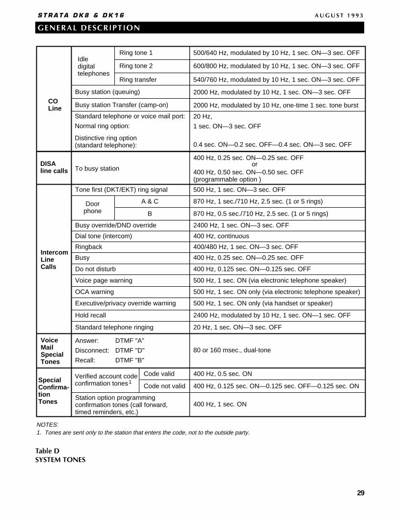
29
GENERAL DESCRIPTION
S T R A T A D K 8 & D K 1 6 A U G U S T 1 9 9 3
Idledigitaltelephones
COLine
IntercomLineCalls
Ring tone 1
Ring tone 2
Ring transfer 540/760 Hz, modulated by 10 Hz, 1 sec. ON—3 sec. OFF
600/800 Hz, modulated by 10 Hz, 1 sec. ON—3 sec. OFF
500/640 Hz, modulated by 10 Hz, 1 sec. ON—3 sec. OFF
2000 Hz, modulated by 10 Hz, one-time 1 sec. tone burst
20 Hz,
1 sec. ON—3 sec. OFF
Busy station Transfer (camp-on)
Standard telephone or voice mail port:
Normal ring option:
500 Hz, 1 sec. ON—3 sec. OFF
Busy override/DND override
Doorphone
A & C 870 Hz, 1 sec./710 Hz, 2.5 sec. (1 or 5 rings)
B 870 Hz, 0.5 sec./710 Hz, 2.5 sec. (1 or 5 rings)
2400 Hz, 1 sec. ON—3 sec. OFF
Dial tone (intercom) 400 Hz, continuous
Ringback 400/480 Hz, 1 sec. ON—3 sec. OFF
Busy 400 Hz, 0.25 sec. ON—0.25 sec. OFF
Do not disturb 400 Hz, 0.125 sec. ON—0.125 sec. OFF
Voice page warning 500 Hz, 1 sec. ON (via electronic telephone speaker)
OCA warning 500 Hz, 1 sec. ON only (via electronic telephone speaker)
Executive/privacy override warning 500 Hz, 1 sec. ON only (via handset or speaker)
Tone first (DKT/EKT) ring signal
Hold recall 2400 Hz, modulated by 10 Hz, 1 sec. ON—1 sec. OFF
Standard telephone ringing 20 Hz, 1 sec. ON—3 sec. OFF
DISAline calls To busy station
400 Hz, 0.25 sec. ON—0.25 sec. OFF
400 Hz, 0.50 sec. ON—0.50 sec. OFF(programmable option )
or
Distinctive ring option (standard telephone): 0.4 sec. ON—0.2 sec. OFF—0.4 sec. ON—3 sec. OFF
VoiceMailSpecialTones
Answer:
Disconnect:
Recall:
DTMF "A"
DTMF "D"
DTMF "B"
80 or 160 msec., dual-tone
NOTES:1. Tones are sent only to the station that enters the code, not to the outside party.
Station option programming confirmation tones (call forward, timed reminders, etc.)
Verified account codeconfirmation tones
Code valid 400 Hz, 0.5 sec. ON
Code not valid 400 Hz, 0.125 sec. ON—0.125 sec. OFF—0.125 sec. ON
400 Hz, 1 sec. ON
SpecialConfirma-tionTones
1
2000 Hz, modulated by 10 Hz, 1 sec. ON—3 sec. OFFBusy station (queuing)
Table DSYSTEM TONES

30
GENERAL DESCRIPTION
S T R A T A D K 8 & D K 1 6 A U G U S T 1 9 9 3
Item Connector TypeSupports Standard Optional
Digital Telephone Circuits (4)
CO Line Circuits (2)
Power Failure Transfer Interface
Battery Backup Interface
Music-On-Hold Interface
600 Ohm page Interface
CO line CKT (1)/Digital Telephone CKT (2) (QCDU)(max. 2 QCDU per system)
Standard TelephoneInterface Unit (QSTU)
2 standard telephone circuits • (max.) QSTU per system
DTMF/ABR Tone Receiver(QRCU/QRCU2A, each containing 3 receiver circuits)
Auto AttendantFeature Key (QKYS1)
Control Relay
Conferences Circuit Interface Unit (QCNU)
SMDR/TTY Interface Unit(QSMU)
25-pair Amphenol
RJ11 Modular
RJ11 Modular
Proprietary Cable/Connector
RCA Jack
RCA Jack
25-pair Amphenol
RJ11 Modular
25-pair Amphenol
Internal
7-pin in-line
25-pair Amphenol
Internal
6-pin Modular(PPTC Adaptor)
Interface
HPFBand cable
*Customer supplied equipment.
• Digital Telephones (with or without PDIU–DI2 or ADM)
• Stand-alone Data Interface Units (PDIU-DS)
• Door Phone Lock/Control Unit (DDCB)
• Loop Start CO Lines
• Standard Telephone (one)*
• Optional HPFB(one or two per system)
• Music-on-hold/BGM Source*
• Amplifier/Speaker*
• Digital Telephones (with or without PDIU–DI2 or ADM)
• Stand-alone Data Interface Units (PDIU-DS)
• Door Phone Lock/Control Unit (DDCB)
• Loop Start CO Line
• Standard Telephones*• Other Single-line
Devices*• Fax Machine*• Voice Mail Devices• Alternate BGM source*• Auto Attendant Digital
Announcers*
• Automatic Busy Redial• Standard telephone ports• DISA• Built-in Auto Attendant
(QRCU2A only)
• Built-in Auto Attendant (plugs into QRCU2A card)
One of the following:• Night Relay• External Page Mute• MOH Control relay
• 2 Simultaneous Conferences
• SMDR Printer*or
• TTY*or
• Modem
Table EDK8 KEY SERVICE UNIT COMPONENTS
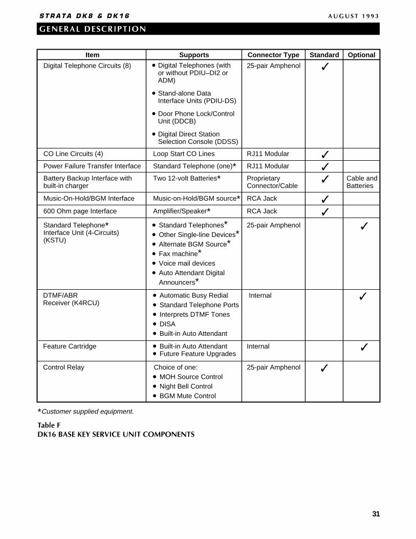
31
GENERAL DESCRIPTION
S T R A T A D K 8 & D K 1 6 A U G U S T 1 9 9 3
Item
Digital Telephone Circuits (8)
CO Line Circuits (4)
Power Failure Transfer Interface
Battery Backup Interface withbuilt-in charger
Music-On-Hold/BGM Interface
600 Ohm page Interface
Standard Telephone*Interface Unit (4-Circuits) (KSTU)
Connector Type
25-pair Amphenol
RJ11 Modular
RJ11 Modular
RCA Jack
RCA Jack
25-pair Amphenol
Internal
Internal
ProprietaryConnector/Cable
DTMF/ABRReceiver (K4RCU)
Supports
Loop Start CO Lines
Standard Telephone (one)*Two 12-volt Batteries*
Music-on-Hold/BGM source*Amplifier/Speaker*
Standard Telephones*Other Single-line Devices*Alternate BGM Source*Fax machine*Voice mail devicesAuto Attendant DigitalAnnouncers*
•
•
•
•
•
•
Automatic Busy RedialStandard Telephone PortsInterprets DTMF TonesDISABuilt-in Auto Attendant
•
•
•
•
•
Feature Cartridge Built-in Auto AttendantFuture Feature Upgrades
•
•
Standard Optional
Digital Telephones (with or without PDIU–DI2 or ADM)
Stand-alone Data Interface Units (PDIU-DS)
Door Phone Lock/Control Unit (DDCB)
Digital Direct Station Selection Console (DDSS)
•
•
•
•
*Customer supplied equipment.
Cable andBatteries
Choice of one:•
•
•
MOH Source ControlNight Bell ControlBGM Mute Control
25-pair AmphenolControl Relay
Table FDK16 BASE KEY SERVICE UNIT COMPONENTS

32
GENERAL DESCRIPTION
S T R A T A D K 8 & D K 1 6 A U G U S T 1 9 9 3
Time is estimated with the following considerations:
1.
2.
3.
4.
5.
6.
Expansion UnitBase Unit
3
4.5
16.0
Quantity of installed PCBs
Approximate (-24v) current drain (DC amperes)
Estimated battery operation time (in hours)
2
3.8
19.0
1
3.1
23.0
KSTU
2.4
31.0
No KSTU
1.7
45.0
Batteries have full charge at start of operation.
Batteries (2) are connected in series.
Batteries are 12VDC, rated at 80 amp/hours each.
System is operating at full load traffic with LCD phones.
Batteries used for this test are gel-cell and maintenance-free. Reserve duration will vary depending upon battery type, age, and manufacturer. These figures should be used as an estimate.
A maximum of three Expansion Key Service Unit slots may be occupied at one time. The fourth slot is reserved for future features.
1.
2.
3.
One HPFB
Two HPFBs
.5 ~ 1.0
1.0 ~ 2.0
Reserve power time varies with system call traffic.
Batteries must have full charge at start of operation.
HPFB recharge time is 48 hours per HPFB.
DK8 (Fully Loaded)
DK16
Estimated Battery Time (hours)
Table GDK8 & DK16 TYPICAL RESERVE POWER DURATION ESTIMATES

33
GENERAL DESCRIPTION
S T R A T A D K 8 & D K 1 6 A U G U S T 1 9 9 3
• Electronic telephones• HDSS console• Alternate BGM source* • EOCU PCB for OCA• External Conference Amplifier*
• Standard telephones*• Voice mail ports*• Off-premises stations*• Other similar devices*• Alternate BGM source*• Auto Attendant
Digital Announcer*
• Central Office loop start lines
• Central Office loopstart lines
See Table I
8 electronic telephonecircuits
8 standard telephonecircuits
4 CO line circuits (lines)
2 CO line circuits/4 digital telephone circuits
See Table I
PEKU
PSTU,RSTU
PESU
PCOU
PIOU, PIOUSRSSU
PCB InterfacesCircuits per PCB
PDKU
Connector
8 digital telephonecircuits
• Digital telephones (with or without PDIU-DI2 or ADM• DDSS console• PDIU-DSs• DDCB
25-pair Amphenol
25-pair Amphenol
25-pair Amphenol
RJ14C modular
RJ14C Modular(CO Line circuits)
25-pair amphenol (PIOU)Spring clip terminal (PIOUS)
KCDU
*Customer supplied equipment.
R48S
8 standard telephonecircuits
• Optionally interfaces to the RSTU to extend loop length ofstandard telephones from 600ohms to 1200 ohms.
25-pair Amphenol
2 standard telephone/4 electronic telephone circuits(standard/electronic telephone ports)
25-pair AmphenolStandard: same as PSTUElectronic: same as PEKU
except PESU does not support HDSS console
• Digital circuits same asPDKU, except no DDSS
25-pair amphenol(digital telephone circuits)
NOTE: X = The option is provided. * = Customer supplied equipment required.
PIOU/PIOUS Interface Option RSSU
*Zone Page Interface (unamplified, 4 zones)
*Night Transfer or Music-on-Hold Control Relay
*Door Lock or External Amplifier Control Relay
*Alarm Sensor
*SMDR output (RS-232/6-wire modular connector)
*Maintenance TTY Port for a Local ASCII Terminal orExternal Modem (RS-232/6-wire modular connector)
Remote Maintenance Modem (IMDU subassembly, no external connector)
PIOU
X
X
X
X
X
X
X
X
PIOUS
X
X
X
X
X
X
Table HDK16 EXPANSION KEY SERVICE UNIT COMPONENTS
Table IDK16 PIOU/PIOUS INTERFACE OPTIONS
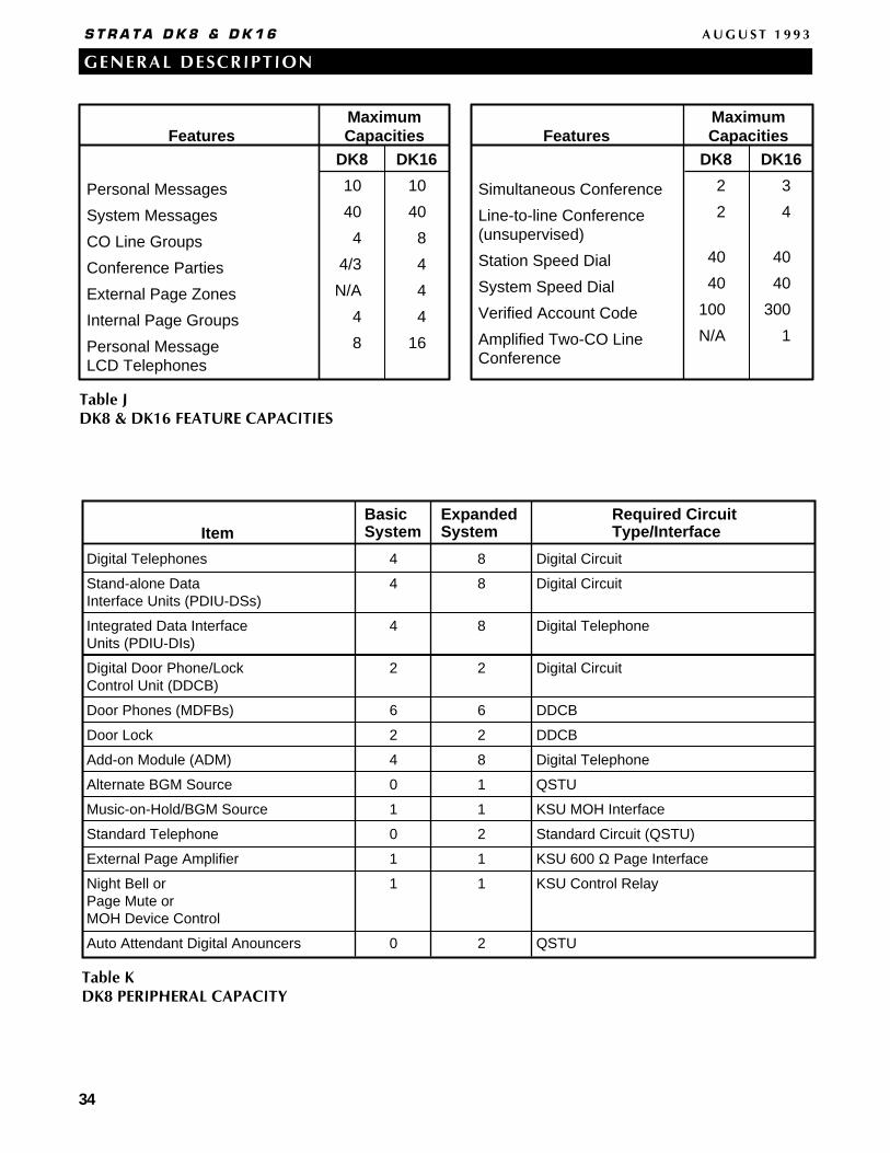
34
GENERAL DESCRIPTION
S T R A T A D K 8 & D K 1 6 A U G U S T 1 9 9 3
Table JDK8 & DK16 FEATURE CAPACITIES
MaximumCapacities
Simultaneous Conference
Line-to-line Conference (unsupervised)
Station Speed Dial
System Speed Dial
Verified Account Code
Amplified Two-CO Line Conference
DK8
2
2
40
40
100
N/A
Personal Messages
System Messages
CO Line Groups
Conference Parties
External Page Zones
Internal Page Groups
Personal MessageLCD Telephones
DK16
10
40
8
4
4
4
16
Features FeaturesMaximumCapacities
DK8
10
40
4
4/3
N/A
4
8
DK16
3
4
40
40
300
1
ItemBasicSystem
ExpandedSystem
Required CircuitType/Interface
Digital Telephones
Stand-alone DataInterface Units (PDIU-DSs)
Integrated Data InterfaceUnits (PDIU-DIs)
Digital Door Phone/LockControl Unit (DDCB)
Door Phones (MDFBs)
Door Lock
Add-on Module (ADM)
Alternate BGM Source
Music-on-Hold/BGM Source
Standard Telephone
External Page Amplifier
Night Bell or Page Mute or MOH Device Control
Auto Attendant Digital Anouncers
Digital Circuit
Digital Circuit
Digital Telephone
Digital Circuit
DDCB
DDCB
Digital Telephone
QSTU
KSU MOH Interface
Standard Circuit (QSTU)
KSU 600 Ω Page Interface
KSU Control Relay
QSTU
4
4
4
2
6
2
4
0
1
0
1
1
0
8
8
8
2
6
2
8
1
1
2
1
1
2
Table KDK8 PERIPHERAL CAPACITY
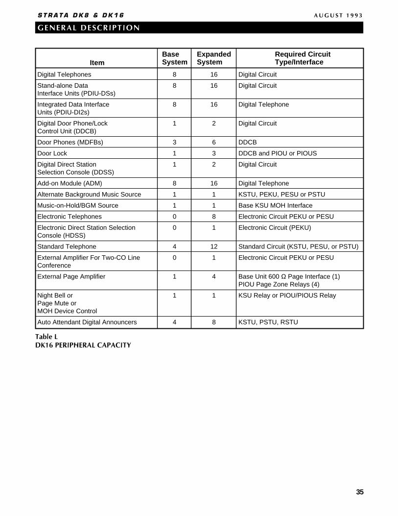
35
GENERAL DESCRIPTION
S T R A T A D K 8 & D K 1 6 A U G U S T 1 9 9 3
ItemBaseSystem
ExpandedSystem
Required CircuitType/Interface
Digital Telephones
Stand-alone DataInterface Units (PDIU-DSs)
Integrated Data InterfaceUnits (PDIU-DI2s)
Digital Door Phone/LockControl Unit (DDCB)
Door Phones (MDFBs)
Door Lock
Digital Direct StationSelection Console (DDSS)
Add-on Module (ADM)
Alternate Background Music Source
Music-on-Hold/BGM Source
Electronic Telephones
Electronic Direct Station Selection Console (HDSS)
Standard Telephone
External Amplifier For Two-CO Line Conference
External Page Amplifier
Night Bell orPage Mute or MOH Device Control
Auto Attendant Digital Announcers
Digital Circuit
Digital Circuit
Digital Telephone
Digital Circuit
DDCB
DDCB and PIOU or PIOUS
Digital Circuit
Digital Telephone
KSTU, PEKU, PESU or PSTU
Base KSU MOH Interface
Electronic Circuit PEKU or PESU
Electronic Circuit (PEKU)
Standard Circuit (KSTU, PESU, or PSTU)
Electronic Circuit PEKU or PESU
Base Unit 600 Ω Page Interface (1) PIOU Page Zone Relays (4)
KSU Relay or PIOU/PIOUS Relay
KSTU, PSTU, RSTU
8
8
8
1
3
1
1
8
1
1
0
0
4
0
1
1
4
16
16
16
2
6
3
2
16
1
1
8
1
12
1
4
1
8
Table LDK16 PERIPHERAL CAPACITY
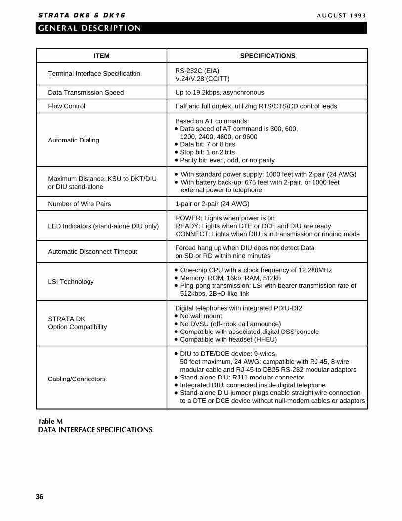
36
GENERAL DESCRIPTION
S T R A T A D K 8 & D K 1 6 A U G U S T 1 9 9 3
Terminal Interface Specification
Data Transmission Speed
Flow Control
Automatic Dialing
Maximum Distance: KSU to DKT/DIU or DIU stand-alone
Number of Wire Pairs
LED Indicators (stand-alone DIU only)
Automatic Disconnect Timeout
LSI Technology
STRATA DKOption Compatibility
Cabling/Connectors
RS-232C (EIA)V.24/V.28 (CCITT)
Up to 19.2kbps, asynchronous
Half and full duplex, utilizing RTS/CTS/CD control leads
With standard power supply: 1000 feet with 2-pair (24 AWG)With battery back-up: 675 feet with 2-pair, or 1000 feet external power to telephone
Based on AT commands:•
•
•
•
Data speed of AT command is 300, 600,1200, 2400, 4800, or 9600Data bit: 7 or 8 bitsStop bit: 1 or 2 bitsParity bit: even, odd, or no parity
1-pair or 2-pair (24 AWG)
POWER: Lights when power is onREADY: Lights when DTE or DCE and DIU are readyCONNECT: Lights when DIU is in transmission or ringing mode
Forced hang up when DIU does not detect Dataon SD or RD within nine minutes
One-chip CPU with a clock frequency of 12.288MHzMemory: ROM, 16kb; RAM, 512kbPing-pong transmission: LSI with bearer transmission rate of512kbps, 2B+D-like link
•
•
•
Digital telephones with integrated PDIU-DI2•
•
•
•
No wall mountNo DVSU (off-hook call announce)Compatible with associated digital DSS consoleCompatible with headset (HHEU)
SPECIFICATIONSITEM
•
•
•
•
•
DIU to DTE/DCE device: 9-wires,50 feet maximum, 24 AWG: compatible with RJ-45, 8-wiremodular cable and RJ-45 to DB25 RS-232 modular adaptorsStand-alone DIU: RJ11 modular connectorIntegrated DIU: connected inside digital telephone
• Stand-alone DIU jumper plugs enable straight wire connectionto a DTE or DCE device without null-modem cables or adaptors
Table MDATA INTERFACE SPECIFICATIONS

37
GENERAL DESCRIPTION
S T R A T A D K 8 & D K 1 6 A U G U S T 1 9 9 3
• Account Codes (Forced/Voluntary/Verified)• All Call Voice Page• Alternate Point Answer• Automatic Hold/Park Recall• Automatic Hold• Automatic Release from Hold/DISA• Automatic Station Relocation• Background Music Interface* • Busy Station Ringing/Transfer• Centrex/PBX Compatible• Centrex Ringing Repeat• CO Line Groups• CO Line Queuing• Conferencing• Credit Card Dialing• DAY/NIGHT Modes• Delayed Ringing• Distinctive CO Line/Intercom Ringing• DTMF Back Tone• DTMF and Dial Pulse CO Line Compatible• DTMF Signal Time (80/160 ms)• Dual FCC Registration• External Page Interface* • Flexible Button Assignment• Flexible Intercom Numbering• Flexible Line Ringing Assignment
§ Immediate§ Delay 1§ Delay 2
• Group Paging• Handsfree Intercom Path (Non-Blocking)• Least Cost Routing
STANDARD• Live System Programming from any DKT/EKT• Memory Protection• Message Waiting Indication• Music-on-Hold Interface*• Night Ringing Answer Code• Non-blocking Talk Paths• Outgoing Call Restriction• Pooled CO Lines• Power Failure Transfer• Privacy/Non-privacy• Relay Service* • Station Hunting• System Programming through Station• System Speed Dial• Tandem CO Line Connections• Tenant Service• Toll Restriction• Toll Restriction Override by System Speed Dial• Transfer Privacy• Traveling Class of Service• Unlimited Handsfree Intercom Paths• Unrestricted Call Transfer over Intercom• Voice Mail Integration
§ Automated Attendant§ Call Forward to Voice Mailbox§ Feature Integration§ Message Waiting Indication§ Voice Mail Control via Digital/Electronic Station§ Voice Mail Identification Codes
• Voice or Tone Signaling§ Tone First§ Voice First
• Alarm Sensor (DK16 only)*• Alternate Background Music Interface*• Amplified Conference Interface (DK16 only)*• Auto Attendant (Built-in)*• Data Switching*• Direct Inward System Access• Door Lock Control*• Door Phones• External Amplified Speaker• Modem Pooling*• Night Ringing Over External Page*
§ Night Pickup Code• Night Ringing Over Selected Page Zones (DK16 only)*
OPTIONAL• Off-premises Station*• Page Zones (DK16 only)*• Printer Sharing*• Relay Service (Expansion Unit-DK16 only)*
§ External Page/Door Lock Relay*§ Night/Hold Relay*
• Remote Administration and Maintenance*• Reserve Power*• Station Message Detail Recording*• Standard Telephone Interface
*May require customer-supplied peripherals; see the detailed feature descriptions.
Table NDK8 & DK16 SYSTEM FEATURES
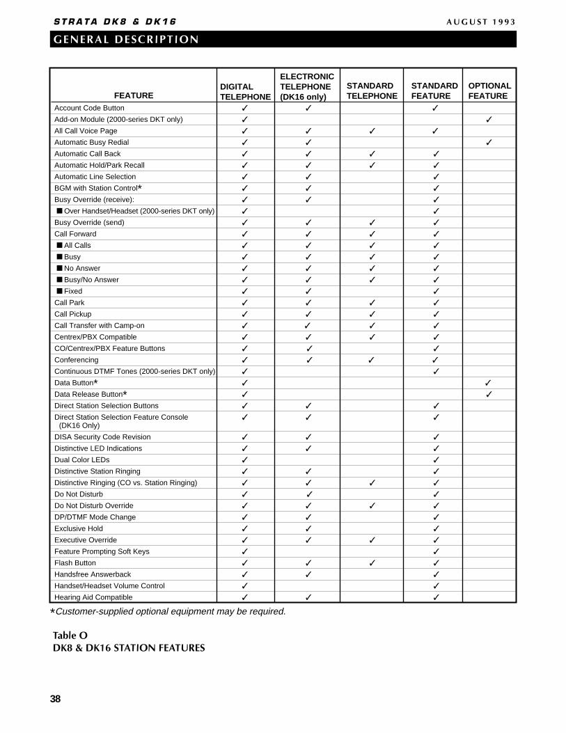
38
GENERAL DESCRIPTION
S T R A T A D K 8 & D K 1 6 A U G U S T 1 9 9 3
FEATURE
DIGITALTELEPHONE
ELECTRONICTELEPHONE(DK16 only)
STANDARDFEATURE
STANDARDTELEPHONE
Account Code Button
Add-on Module (2000-series DKT only)
All Call Voice Page
Automatic Busy Redial
Automatic Call Back
Automatic Hold/Park Recall
Automatic Line Selection
BGM with Station Control*
Busy Override (receive):
Over Handset/Headset (2000-series DKT only)
Busy Override (send)
Call Forward
All Calls
Busy
No Answer
Busy/No Answer
Fixed
Call Park
Call Pickup
Call Transfer with Camp-on
Centrex/PBX Compatible
CO/Centrex/PBX Feature Buttons
Conferencing
Continuous DTMF Tones (2000-series DKT only)
Data Button*Data Release Button*Direct Station Selection Buttons
Direct Station Selection Feature Console(DK16 Only)
DISA Security Code Revision
Distinctive LED Indications
Dual Color LEDs
Distinctive Station Ringing
Distinctive Ringing (CO vs. Station Ringing)
Do Not Disturb
Do Not Disturb Override
DP/DTMF Mode Change
Exclusive Hold
Executive Override
Feature Prompting Soft Keys
Flash Button
Handsfree Answerback
Handset/Headset Volume Control
Hearing Aid Compatible
OPTIONALFEATURE
*Customer-supplied optional equipment may be required.
Table ODK8 & DK16 STATION FEATURES
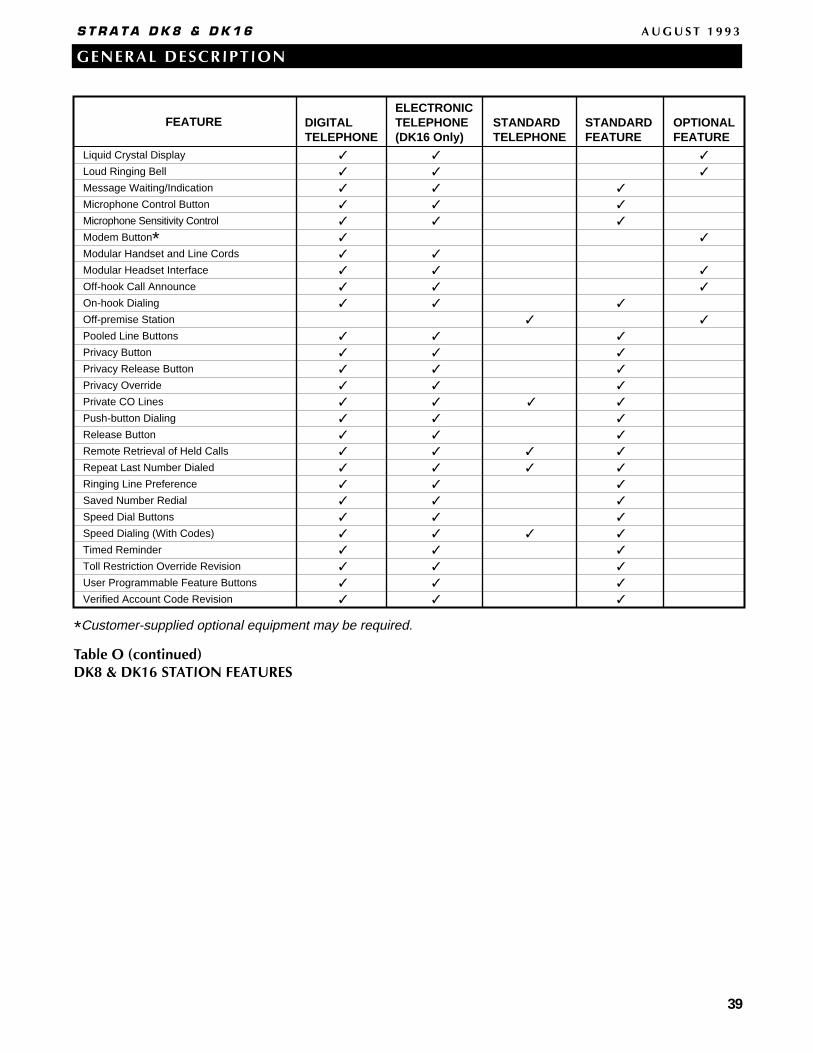
39
GENERAL DESCRIPTION
S T R A T A D K 8 & D K 1 6 A U G U S T 1 9 9 3
FEATURE
DIGITALTELEPHONE
ELECTRONICTELEPHONE(DK16 Only)
STANDARDFEATURE
STANDARDTELEPHONE
Liquid Crystal Display
Loud Ringing Bell
Message Waiting/Indication
Microphone Control Button
Microphone Sensitivity Control
Modem Button*Modular Handset and Line Cords
Modular Headset Interface
Off-hook Call Announce
On-hook Dialing
Off-premise Station
Pooled Line Buttons
Privacy Button
Privacy Release Button
Privacy Override
Private CO Lines
Push-button Dialing
Release Button
Remote Retrieval of Held Calls
Repeat Last Number Dialed
Ringing Line Preference
Saved Number Redial
Speed Dial Buttons
Speed Dialing (With Codes)
Timed Reminder
Toll Restriction Override Revision
User Programmable Feature Buttons
Verified Account Code Revision
OPTIONALFEATURE
*Customer-supplied optional equipment may be required.
Table O (continued)DK8 & DK16 STATION FEATURES
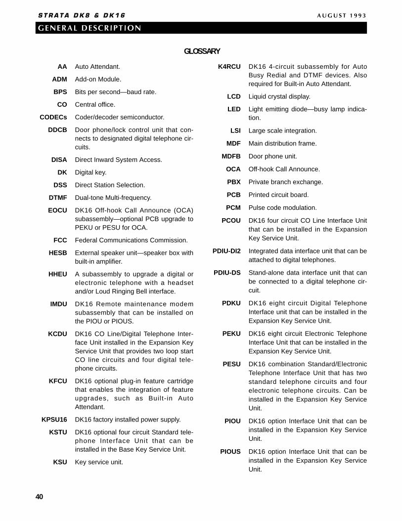
40
GENERAL DESCRIPTION
S T R A T A D K 8 & D K 1 6 A U G U S T 1 9 9 3
AA Auto Attendant.
ADM Add-on Module.
BPS Bits per second—baud rate.
CO Central office.
CODECs Coder/decoder semiconductor.
DDCB Door phone/lock control unit that con-nects to designated digital telephone cir-cuits.
DISA Direct Inward System Access.
DK Digital key.
DSS Direct Station Selection.
DTMF Dual-tone Multi-frequency.
EOCU DK16 Off-hook Call Announce (OCA)subassembly—optional PCB upgrade toPEKU or PESU for OCA.
FCC Federal Communications Commission.
HESB External speaker unit—speaker box withbuilt-in amplifier.
HHEU A subassembly to upgrade a digital orelectronic telephone with a headsetand/or Loud Ringing Bell interface.
IMDU DK16 Remote maintenance modemsubassembly that can be installed onthe PIOU or PIOUS.
KCDU DK16 CO Line/Digital Telephone Inter-face Unit installed in the Expansion KeyService Unit that provides two loop startCO line circuits and four digital tele-phone circuits.
KFCU DK16 optional plug-in feature cartridgethat enables the integration of featureupgrades, such as Built- in AutoAttendant.
KPSU16 DK16 factory installed power supply.
KSTU DK16 optional four circuit Standard tele-phone Interface Unit that can beinstalled in the Base Key Service Unit.
KSU Key service unit.
K4RCU DK16 4-circuit subassembly for AutoBusy Redial and DTMF devices. Alsorequired for Built-in Auto Attendant.
LCD Liquid crystal display.
LED Light emitting diode—busy lamp indica-tion.
LSI Large scale integration.
MDF Main distribution frame.
MDFB Door phone unit.
OCA Off-hook Call Announce.
PBX Private branch exchange.
PCB Printed circuit board.
PCM Pulse code modulation.
PCOU DK16 four circuit CO Line Interface Unitthat can be installed in the ExpansionKey Service Unit.
PDIU-DI2 Integrated data interface unit that can beattached to digital telephones.
PDIU-DS Stand-alone data interface unit that canbe connected to a digital telephone cir-cuit.
PDKU DK16 eight circuit Digital TelephoneInterface unit that can be installed in theExpansion Key Service Unit.
PEKU DK16 eight circuit Electronic TelephoneInterface Unit that can be installed in theExpansion Key Service Unit.
PESU DK16 combination Standard/ElectronicTelephone Interface Unit that has twostandard telephone circuits and fourelectronic telephone circuits. Can beinstalled in the Expansion Key ServiceUnit.
PIOU DK16 option Interface Unit that can beinstalled in the Expansion Key ServiceUnit.
PIOUS DK16 option Interface Unit that can beinstalled in the Expansion Key ServiceUnit.
GLOSSARY
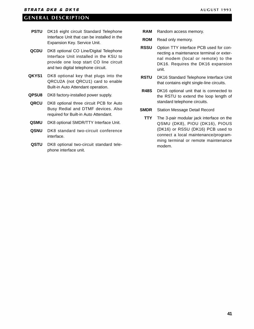
41
GENERAL DESCRIPTION
S T R A T A D K 8 & D K 1 6 A U G U S T 1 9 9 3
PSTU DK16 eight circuit Standard TelephoneInterface Unit that can be installed in theExpansion Key. Service Unit.
QCDU DK8 optional CO Line/Digital TelephoneInterface Unit installed in the KSU toprovide one loop start CO line circuitand two digital telephone circuit.
QKYS1 DK8 optional key that plugs into theQRCU2A (not QRCU1) card to enableBuilt-in Auto Attendant operation.
QPSU8 DK8 factory-installed power supply.
QRCU DK8 optional three circuit PCB for AutoBusy Redial and DTMF devices. Alsorequired for Built-in Auto Attendant.
QSMU DK8 optional SMDR/TTY Interface Unit.
QSNU DK8 standard two-circuit conferenceinterface.
QSTU DK8 optional two-circuit standard tele-phone interface unit.
RAM Random access memory.
ROM Read only memory.
RSSU Option TTY interface PCB used for con-necting a maintenance terminal or exter-nal modem (local or remote) to theDK16. Requires the DK16 expansionunit.
RSTU DK16 Standard Telephone Interface Unitthat contains eight single-line circuits.
R48S DK16 optional unit that is connected tothe RSTU to extend the loop length ofstandard telephone circuits.
SMDR Station Message Detail Record
TTY The 3-pair modular jack interface on theQSMU (DK8), PIOU (DK16), PIOUS(DK16) or RSSU (DK16) PCB used toconnect a local maintenance/program-ming terminal or remote maintenancemodem.