Digital Image Steganography using PVD and Modulo Operation
11
Vol. 10/No. 2 (2018) INTERNETWORKING INDONESIA JOURNAL 3 ISSN: 1942-9703 / CC BY-NC-ND Abstract— This paper proposes an image steganographic approach using the principle of pixel value differencing (PVD) and modulo operation (MO). The major contributions of the proposed approach are: (i) increase in peak signal-to-noise ratio (PSNR), (ii) increase in hiding capacity, and (iii) avoidance of fall off boundary problem (FOBP). At first, the image is partitioned into non-overlapping blocks consisting of three consecutive pixels. Then, the secret data is embedded in a block using two phases, (i) pixel difference modulo operation (PDMO) phase, and (ii) average PVD (APVD) readjustment phase. In the first phase, the difference between two consecutive pixels of a block is found and using an adaptive range table and modulo operation the secret data are embedded. In the second phase, the average of the first two stego-pixels of the block and the third pixel is considered for data embedding using PVD approach. The result of the proposed approach has been compared with existing approaches and found to be improved. Index Terms— Steganography, capacity, average pixel value differencing, modulo operation. I. INTRODUCTION he evolution of digitization led to massive improvement in the field of digital communication, with an exponential growth in the number of network users [1]. In this aspect, protection to the confidential data and intellectual property rights became very important [2]. So, data hiding strategies plays vital role in ensuring the secured delivery of the data to the recipient. Strategies like, (i) steganography and (ii) cryptography are being used extensively to protect the data [3]. Steganography is an art of covert communication, which conceals the data inside a multimedia carrier like image, audio, video, or text. Image steganography uses an apparently innocuous carrier image to hide the secret data [4]. Manuscript received 9 September, 2018. This work is an independent work and no financial assistance has been received for this work. Aditya Kumar Sahu is a research scholar in Koneru Lakshmaiah Education Foundation, Vaddeswaram, Guntur, Andhra Pradesh, 522502, India (phone: +91 7288890001; e-mail: [email protected]) He is working as an assistant professor in the Department of Computer Science and Engineering, GMRIT, Rajam, Andhra Pradesh, 532127, India Gandharba Swain is working as a Professor in the Department of Computer Science & Engineering, Koneru Lakshmaiah Education Foundation, Vaddeswaram, Guntur, Andhra Pradesh, 522502, India (e-mail: [email protected]) The earliest and simplest steganography approach is the least significant bit (LSB) substitution [5]. The LSB approaches conceal the secret data bits directly in the least significant bit positions of the pixels in an image [6]. Several researchers have proposed many ways to conceal the secret data using the principle of LSB substitution [7-10, 36-38]. PVD steganography was proposed in [11] by Wu and Tsai. The motive behind the PVD approach is to conceal more number of bits in edge areas as compared to the smooth areas, because the edge areas can tolerate more changes than that of the smooth areas. Yang et al. [12] obtained pixel value differences in various ways in a four-pixel block. Jung [13] proposed PVD based data hiding approach using basis pixel. The basis pixel is identified using an index function. Lee et al. [14] proposed tri-way pixel-value differencing using compression technique. Swain [15] suggested an adaptive PVD based approach with 2×2 and 3×3 pixel blocks for embedding the secret data. The data embedding is done by exploiting vertical, horizontal and diagonal edges for each block. The experimental result shows that the approach avoids FOBP. Several researchers have proposed various PVD approaches [16-17, 39]. Wu et al. [18] proposed a novel image steganography approach combining the PVD and LSB substitution. The capacity has been improved as compared to Wu and Tsai’s [11] PVD. Khodaei and Faez [19] considered a block with three consecutive pixels for data hiding. The central pixel has been chosen as a base pixel, and 3- LSB substitution is applied to it. Further, the difference between the central and other two pixels is obtained, and PVD is applied. The capacity is improved as compared to Wu et al.’s [18] technique. Improved LSB and PVD approaches have been suggested in [20-24]. Wang et al. [25] used PVD to improve the security against RS attack, and modulus function to improve the embedding rate. At first, PVD is applied on two consecutive pixels and later, using the modulus function the remainder of the pixels is found to conceal the secret data. From the experimental investigation, it is observed that Wang et al.’s [25] approach successfully avoids the FOBP. The turnover strategy [26] successfully avoids the step effect caused in [25]. Maleki et al. [27] suggested adaptive and non-adaptive steganography for hiding the secret data. Several researchers have proposed different approaches using the principle of PVD and MF Digital Image Steganography using PVD and Modulo Operation Aditya Kumar Sahu and Gandharba Swain T
Transcript of Digital Image Steganography using PVD and Modulo Operation
Vol. 10/No. 2 (2018) INTERNETWORKING INDONESIA JOURNAL 3
ISSN: 1942-9703 / CC BY-NC-ND
Abstract— This paper proposes an image steganographic
approach using the principle of pixel value differencing (PVD) and modulo operation (MO). The major contributions of the proposed approach are: (i) increase in peak signal-to-noise ratio (PSNR), (ii) increase in hiding capacity, and (iii) avoidance of fall off boundary problem (FOBP). At first, the image is partitioned into non-overlapping blocks consisting of three consecutive pixels. Then, the secret data is embedded in a block using two phases, (i) pixel difference modulo operation (PDMO) phase, and (ii) average PVD (APVD) readjustment phase. In the first phase, the difference between two consecutive pixels of a block is found and using an adaptive range table and modulo operation the secret data are embedded. In the second phase, the average of the first two stego-pixels of the block and the third pixel is considered for data embedding using PVD approach. The result of the proposed approach has been compared with existing approaches and found to be improved.
Index Terms— Steganography, capacity, average pixel value differencing, modulo operation.
I. INTRODUCTION he evolution of digitization led to massive improvement in the field of digital communication, with an exponential
growth in the number of network users [1]. In this aspect, protection to the confidential data and intellectual property rights became very important [2]. So, data hiding strategies plays vital role in ensuring the secured delivery of the data to the recipient. Strategies like, (i) steganography and (ii) cryptography are being used extensively to protect the data [3]. Steganography is an art of covert communication, which conceals the data inside a multimedia carrier like image, audio, video, or text. Image steganography uses an apparently innocuous carrier image to hide the secret data [4].
Manuscript received 9 September, 2018. This work is an independent work
and no financial assistance has been received for this work. Aditya Kumar Sahu is a research scholar in Koneru Lakshmaiah Education
Foundation, Vaddeswaram, Guntur, Andhra Pradesh, 522502, India (phone: +91 7288890001; e-mail: [email protected])
He is working as an assistant professor in the Department of Computer Science and Engineering, GMRIT, Rajam, Andhra Pradesh, 532127, India
Gandharba Swain is working as a Professor in the Department of Computer Science & Engineering, Koneru Lakshmaiah Education Foundation, Vaddeswaram, Guntur, Andhra Pradesh, 522502, India (e-mail: [email protected])
The earliest and simplest steganography approach is the least significant bit (LSB) substitution [5]. The LSB approaches conceal the secret data bits directly in the least significant bit positions of the pixels in an image [6]. Several researchers have proposed many ways to conceal the secret data using the principle of LSB substitution [7-10, 36-38].
PVD steganography was proposed in [11] by Wu and Tsai. The motive behind the PVD approach is to conceal more number of bits in edge areas as compared to the smooth areas, because the edge areas can tolerate more changes than that of the smooth areas. Yang et al. [12] obtained pixel value differences in various ways in a four-pixel block. Jung [13] proposed PVD based data hiding approach using basis pixel. The basis pixel is identified using an index function. Lee et al. [14] proposed tri-way pixel-value differencing using compression technique. Swain [15] suggested an adaptive PVD based approach with 2×2 and 3×3 pixel blocks for embedding the secret data. The data embedding is done by exploiting vertical, horizontal and diagonal edges for each block. The experimental result shows that the approach avoids FOBP. Several researchers have proposed various PVD approaches [16-17, 39].
Wu et al. [18] proposed a novel image steganography approach combining the PVD and LSB substitution. The capacity has been improved as compared to Wu and Tsai’s [11] PVD. Khodaei and Faez [19] considered a block with three consecutive pixels for data hiding. The central pixel has been chosen as a base pixel, and 3- LSB substitution is applied to it. Further, the difference between the central and other two pixels is obtained, and PVD is applied. The capacity is improved as compared to Wu et al.’s [18] technique. Improved LSB and PVD approaches have been suggested in [20-24].
Wang et al. [25] used PVD to improve the security against RS attack, and modulus function to improve the embedding rate. At first, PVD is applied on two consecutive pixels and later, using the modulus function the remainder of the pixels is found to conceal the secret data. From the experimental investigation, it is observed that Wang et al.’s [25] approach successfully avoids the FOBP. The turnover strategy [26] successfully avoids the step effect caused in [25]. Maleki et al. [27] suggested adaptive and non-adaptive steganography for hiding the secret data. Several researchers have proposed different approaches using the principle of PVD and MF
Digital Image Steganography using PVD and Modulo Operation
Aditya Kumar Sahu and Gandharba Swain
T
4 INTERNETWORKING INDONESIA JOURNAL SAHU & SWAIN approaches [28-32, 35].
The PVD based approaches suffers from two major issues, (i) fall off boundary problem and (ii) low hiding capacity. The proposed approach addresses these issues. The major improvements of the proposed paper can be summarized into the following aspects: I. A robust image steganography approach using the
benefits of PVD and modulo operation is developed to improve the quality of the stego-image in order to resist RS attack.
II. The proposed approach provides high hiding capacity by producing an additional pixel by performing the average from the first two stego-pixels to hide the secret data.
III. Finally, using the pixel readjustment process FOBP is avoided.
The remainder of the paper is arranged as follows. Section II and III will introduce the related work proposed by Wu and Tsai [11] and Khodaei and Faez [19]. Section IV will analyze the FOBP issues of Khodaei and Faez’s [19] approach. Section V will discuss Sahu and Swain’s [35] approach. Section VI will propose PVD and modulo operation approach and Section VII will illustrate an example for the proposed approach. Simulation results and comparisons to demonstrate the efficiency of the proposed approach will be given in Section VIII. Section IX will conclude the work briefly.
II. REVIEW OF PIXEL VALUE DIFFERENCING (PVD) APPROACH [11]
In this section, we discuss the PVD approach proposed by Wu and Tsai [11]. At first, the original image is divided into blocks consisting of two consecutive pixels. The embedding and extraction steps are explained below.
A. The PVD Embedding Steps Step 1: Let g1 and g2 be the two consecutive pixels of a block.
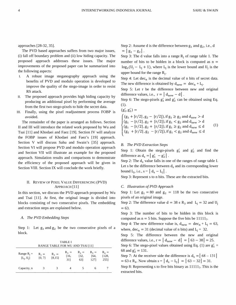
Step 2: Assume d is the difference between g1 and g2, i.e., d = │g1 − g2│. Step 3: The d value falls into a range Rj of range table 1. The number of bits to be hidden in a block is computed as n = log2(Uj − Lj + 1), where Lj is the lower bound and Uj is the upper bound for the range Rj. Step 4: Let decn is the decimal value of n bits of secret data. The new difference is obtained by dnew = decn + Lj. Step 5: Let r be the difference between new and original difference values, i.e., r = │dnew − d│. Step 6: The stego-pixels g1′ and g2′ can be obtained using Eq. (1). (g1′ , g2′ ) =
⎩⎪⎨
⎪⎧
(g1 + ⌈r 2⌉⁄ , g2 − ⌊r 2⌋⁄ ), if g1 ≥ g2 and dnew > d (g1 − ⌊r 2⌋⁄ , g2 + ⌈r 2⌉⁄ ), if g1 < g2 and dnew > d (g1 − ⌈r 2⌉⁄ , g2 + ⌊r 2⌋⁄ ), if g1 ≥ g2 and dnew ≤ d (g1 + ⌈r 2⌉⁄ , g2 − ⌊r 2⌋⁄ ), if g1 < g2 and dnew ≤ d
(1)
B. The PVD Extraction Steps Step 1: Obtain the stego-pixels g1′ and g2′ and find the difference as ds =│g1′ − g2′ │. Step 2: The ds value falls in one of the ranges of range table I. Let s be the difference between ds and its corresponding lower bound Lj, i.e., s = │ds − Lj│. Step 3: Represent s to n bits. These are the extracted bits.
C. Illustration of PVD Approach Step 1: Let g1 = 80 and g2 = 118 be the two consecutive pixels of an original image. Step 2: The difference value d = 38 ϵ R3 and Lj = 32 and Uj = 63. Step 3: The number of bits to be hidden in this block is computed as n = 5 bits. Suppose the five bits be 111112. Step 4: The new difference value is, dnew = decn + Lj = 63, where, decn = 31 (decimal value of n bits) and Lj = 32. Step 5: The difference between the new and original difference values, i.e., r = │dnew − d│ = │63 − 38│= 25. Step 6: The stego-pixel values obtained using Eq. (1) are g1′ = 68 and g2′ = 131. Step 7: At the receiver side the difference is ds =│68 – 131│ = 63 ϵ R4. Now obtain s = │ds − Lj│ = │63 − 32│= 31. Step 8: Representing s to five bits binary as 111112. This is the extracted bits.
TABLE I RANGE TABLE FOR WU AND TSAI [11]
Range Rj = [Lj, Uj]
R1 = [0, 7]
R2 = [8,15]
R3 = [16, 31]
R4 = [32, 63]
R5 = [64, 127]
R6 = [128, 255]
Capacity, n 3 3 4 5 6 7
Vol. 10/No. 2 (2018) INTERNETWORKING INDONESIA JOURNAL 5
ISSN: 1942-9703 / CC BY-NC-ND
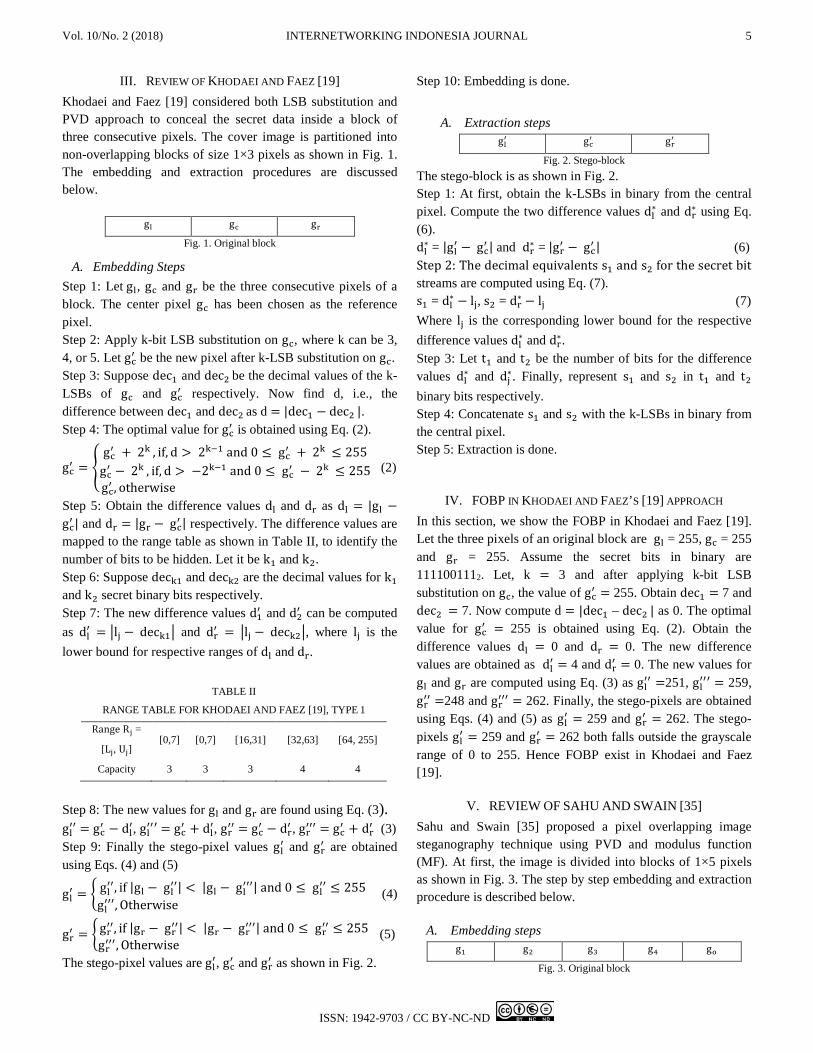
III. REVIEW OF KHODAEI AND FAEZ [19] Khodaei and Faez [19] considered both LSB substitution and PVD approach to conceal the secret data inside a block of three consecutive pixels. The cover image is partitioned into non-overlapping blocks of size 1×3 pixels as shown in Fig. 1. The embedding and extraction procedures are discussed below.
gl gc gr Fig. 1. Original block
A. Embedding Steps Step 1: Let gl, gc and gr be the three consecutive pixels of a block. The center pixel gc has been chosen as the reference pixel. Step 2: Apply k-bit LSB substitution on gc, where k can be 3, 4, or 5. Let gc′ be the new pixel after k-LSB substitution on gc. Step 3: Suppose dec1 and dec2 be the decimal values of the k-LSBs of gc and gc′ respectively. Now find d, i.e., the difference between dec1 and dec2 as d = |dec1 − dec2 |. Step 4: The optimal value for gc′ is obtained using Eq. (2).
gc′ = �
gc′ + 2k , if, d > 2k−1 and 0 ≤ gc′ + 2k ≤ 255
gc′ − 2k , if, d > −2k−1 and 0 ≤ gc′ − 2k ≤ 255gc′ , otherwise
(2)
Step 5: Obtain the difference values dl and dr as dl = |gl − gc′ | and dr = |gr − gc′ | respectively. The difference values are mapped to the range table as shown in Table II, to identify the number of bits to be hidden. Let it be k1 and k2. Step 6: Suppose deck1 and deck2 are the decimal values for k1 and k2 secret binary bits respectively. Step 7: The new difference values d1′ and d2′ can be computed as dl′ = �lj − deck1� and dr′ = �lj − deck2�, where lj is the lower bound for respective ranges of dl and dr.
Step 8: The new values for gl and gr are found using Eq. (3). gl′′ = gc′ − dl′, gl′′′ = gc′ + dl′, gr′′ = gc′ − dr′ , gr′′′ = gc′ + dr′ (3) Step 9: Finally the stego-pixel values gl′ and gr′ are obtained using Eqs. (4) and (5)
gl′ = �
gl′′, if |gl − gl′′| < |gl − gl′′′| and 0 ≤ gl′′ ≤ 255 gl′′′, Otherwise
(4)
gr′ = �
gr′′, if |gr − gr′′| < |gr − gr′′′| and 0 ≤ gr′′ ≤ 255 gr′′′, Otherwise
(5)
The stego-pixel values are gl′, gc′ and gr′ as shown in Fig. 2.
Step 10: Embedding is done.
A. Extraction steps gl′ gc′ gr′
Fig. 2. Stego-block The stego-block is as shown in Fig. 2. Step 1: At first, obtain the k-LSBs in binary from the central pixel. Compute the two difference values dl∗ and dr∗ using Eq. (6). dl∗ = |gl′ − gc′ | and dr∗ = |gr′ − gc′ | (6) Step 2: The decimal equivalents s1 and s2 for the secret bit streams are computed using Eq. (7). s1 = dl∗ − lj, s2 = dr∗ − lj (7) Where lj is the corresponding lower bound for the respective difference values dl∗ and dr∗. Step 3: Let t1 and t2 be the number of bits for the difference values dl∗ and dj∗. Finally, represent s1 and s2 in t1 and t2 binary bits respectively. Step 4: Concatenate s1 and s2 with the k-LSBs in binary from the central pixel. Step 5: Extraction is done.
IV. FOBP IN KHODAEI AND FAEZ’S [19] APPROACH In this section, we show the FOBP in Khodaei and Faez [19]. Let the three pixels of an original block are gl = 255, gc = 255 and gr = 255. Assume the secret bits in binary are 1111001112. Let, k = 3 and after applying k-bit LSB substitution on gc, the value of gc′ = 255. Obtain dec1 = 7 and dec2 = 7. Now compute d = |dec1 – dec2 | as 0. The optimal value for gc′ = 255 is obtained using Eq. (2). Obtain the difference values dl = 0 and dr = 0. The new difference values are obtained as dl′ = 4 and dr′ = 0. The new values for gl and gr are computed using Eq. (3) as gl′′ =251, gl′′′ = 259, gr′′ =248 and gr′′′ = 262. Finally, the stego-pixels are obtained using Eqs. (4) and (5) as gl′ = 259 and gr′ = 262. The stego-pixels gl′ = 259 and gr′ = 262 both falls outside the grayscale range of 0 to 255. Hence FOBP exist in Khodaei and Faez [19].
V. REVIEW OF SAHU AND SWAIN [35] Sahu and Swain [35] proposed a pixel overlapping image steganography technique using PVD and modulus function (MF). At first, the image is divided into blocks of 1×5 pixels as shown in Fig. 3. The step by step embedding and extraction procedure is described below.
A. Embedding steps g1 g2 g3 g4 go
Fig. 3. Original block
TABLE II
RANGE TABLE FOR KHODAEI AND FAEZ [19], TYPE 1
Range Rj =
[Lj, Uj] [0,7] [0,7] [16,31] [32,63] [64, 255]
Capacity 3 3 3 4 4
6 INTERNETWORKING INDONESIA JOURNAL SAHU & SWAIN Step 1: Find the difference value di (for i = 1 to 4) using Eq. (8). di = |gi − go|, for i = 1 to 4 (8) Step 2: Now using the Table III, based on di value, take b bits of data from secret binary data stream and convert to its decimal value si. Obtain the new difference value di′ using Eq. (9). di′ = Lj + si, for i = 1 to 4 (9) Step 3: Obtain the new values gi′ and gi′′ using Eqs. (10) and (11), respectively. gi′ = (go − di′) (10) gi′′ = (go + di′) (11) Step 4: Finally, gi∗ (i = 1 to 4) is computed using Eq. (12)
gi∗ = �gi′, if |gi − gi′| < |gi − gi′′| and 0 ≤ gi′ ≤ 255 gi′′, otherwise (12)
Step 5: Let sd be the decimal value for the next three bits of secret data. The stego-pixel go∗ is found using Eq. (13) or Eq. (14). If go mod 8 = 0 or 1 or 2 or 3, then Eq. (13), else Eq. (14) is used to compute go∗ .
go∗ = � go − (go mod 8 − sd), if |go mod 8 − sd| ≤ 3 go − (8 + go mod 8 − sd), if |go mod 8 − sd| > 3
(13)
go∗ = � go − (go mod 8 − sd), if |go mod 8 − sd| ≤ 4 go + (8 + go mod 8 − sd), if |go mod 8 − sd| > 4
(14)
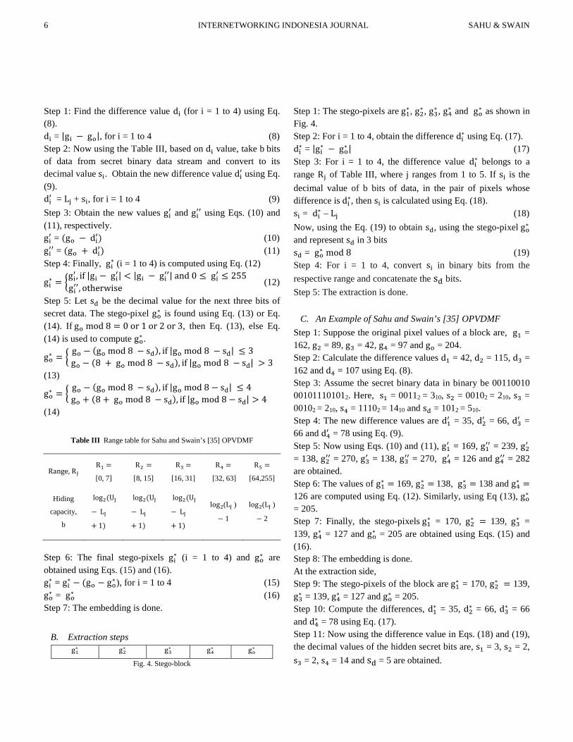
Table III Range table for Sahu and Swain’s [35] OPVDMF
Range, RJ R1 =
[0, 7]
R2 =
[8, 15]
R3 =
[16, 31]
R4 =
[32, 63]
R5 =
[64,255]
Hiding
capacity,
b
log2(UJ
− LJ+ 1)
log2(UJ
− LJ+ 1)
log2(UJ
− LJ+ 1)
log2(LJ )
− 1
log2(LJ )
− 2
Step 6: The final stego-pixels gi∗ (i = 1 to 4) and go∗ are obtained using Eqs. (15) and (16). gi∗ = gi∗ − (go − go∗ ), for i = 1 to 4 (15) go∗ = go∗ (16) Step 7: The embedding is done.
B. Extraction steps g1∗ g2∗ g3∗ g4∗ go∗
Fig. 4. Stego-block
Step 1: The stego-pixels are g1∗ , g2∗ , g3∗ , g4∗ and go∗ as shown in Fig. 4. Step 2: For i = 1 to 4, obtain the difference di∗ using Eq. (17). di∗ = |gi∗ − go∗ | (17) Step 3: For i = 1 to 4, the difference value di∗ belongs to a range Rj of Table III, where j ranges from 1 to 5. If si is the decimal value of b bits of data, in the pair of pixels whose difference is di∗, then si is calculated using Eq. (18). si = di∗ – Lj (18) Now, using the Eq. (19) to obtain sd, using the stego-pixel go∗ and represent sd in 3 bits sd = go∗ mod 8 (19) Step 4: For i = 1 to 4, convert si in binary bits from the respective range and concatenate the sd bits. Step 5: The extraction is done.
C. An Example of Sahu and Swain’s [35] OPVDMF Step 1: Suppose the original pixel values of a block are, g1 = 162, g2 = 89, g3 = 42, g4 = 97 and go = 204. Step 2: Calculate the difference values d1 = 42, d2 = 115, d3 = 162 and d4 = 107 using Eq. (8). Step 3: Assume the secret binary data in binary be 00110010 001011101012. Here, s1 = 00112 = 310, s2 = 00102 = 210, s3 = 00102 = 210, s4 = 11102 = 1410 and sd = 1012 = 510. Step 4: The new difference values are d1′ = 35, d2′ = 66, d3′ = 66 and d4′ = 78 using Eq. (9). Step 5: Now using Eqs. (10) and (11), g1′ = 169, g1′′ = 239, g2′ = 138, g2′′ = 270, g3′ = 138, g3′′ = 270, g4′ = 126 and g4′′ = 282 are obtained. Step 6: The values of g1∗ = 169, g2∗ = 138, g3∗ = 138 and g4∗ = 126 are computed using Eq. (12). Similarly, using Eq (13), go∗ = 205. Step 7: Finally, the stego-pixels g1∗ = 170, g2∗ = 139, g3∗ = 139, g4∗ = 127 and go∗ = 205 are obtained using Eqs. (15) and (16). Step 8: The embedding is done. At the extraction side, Step 9: The stego-pixels of the block are g1∗ = 170, g2∗ = 139, g3∗ = 139, g4∗ = 127 and go∗ = 205. Step 10: Compute the differences, d1∗ = 35, d2∗ = 66, d3∗ = 66 and d4∗ = 78 using Eq. (17). Step 11: Now using the difference value in Eqs. (18) and (19), the decimal values of the hidden secret bits are, s1 = 3, s2 = 2, s3 = 2, s4 = 14 and sd = 5 are obtained.
Vol. 10/No. 2 (2018) INTERNETWORKING INDONESIA JOURNAL 7
ISSN: 1942-9703 / CC BY-NC-ND
Step 12: For i = 1 to 4, convert s1, s2, s3 and s4 to 4 binary bits. Similarly, convert sd to 3 binary bits. The extracted binary bits are 00110010001011101012. Step 13: The extraction is done.
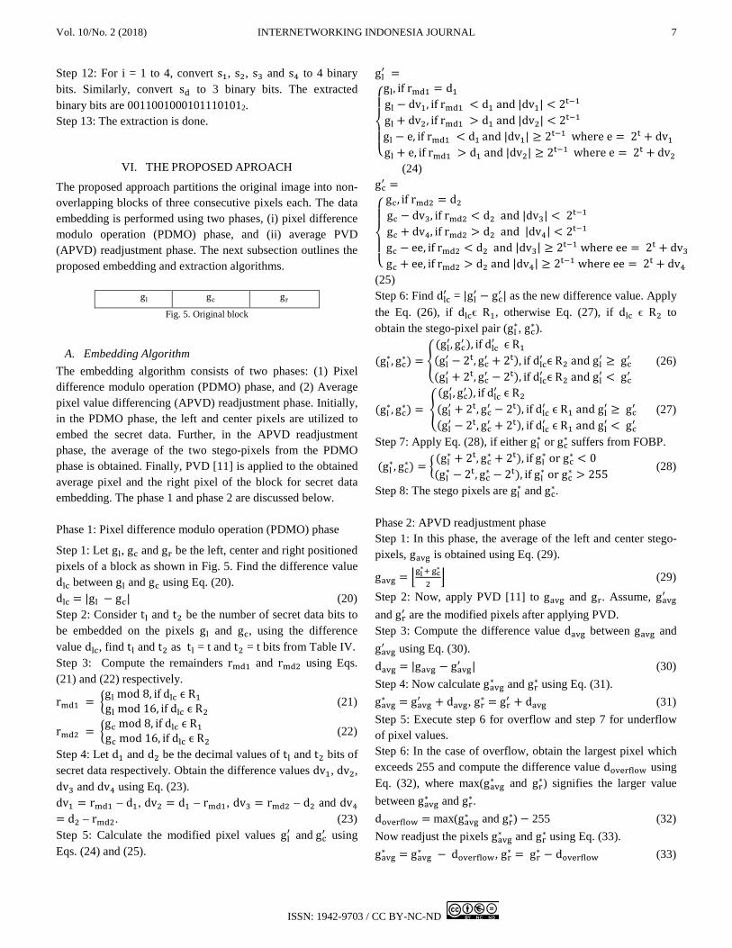
VI. THE PROPOSED APROACH
The proposed approach partitions the original image into non-overlapping blocks of three consecutive pixels each. The data embedding is performed using two phases, (i) pixel difference modulo operation (PDMO) phase, and (ii) average PVD (APVD) readjustment phase. The next subsection outlines the proposed embedding and extraction algorithms.
gl gc gr
Fig. 5. Original block
A. Embedding Algorithm The embedding algorithm consists of two phases: (1) Pixel difference modulo operation (PDMO) phase, and (2) Average pixel value differencing (APVD) readjustment phase. Initially, in the PDMO phase, the left and center pixels are utilized to embed the secret data. Further, in the APVD readjustment phase, the average of the two stego-pixels from the PDMO phase is obtained. Finally, PVD [11] is applied to the obtained average pixel and the right pixel of the block for secret data embedding. The phase 1 and phase 2 are discussed below. Phase 1: Pixel difference modulo operation (PDMO) phase
Step 1: Let gl, gc and gr be the left, center and right positioned pixels of a block as shown in Fig. 5. Find the difference value dlc between gl and gc using Eq. (20). dlc = |gl − gc| (20) Step 2: Consider tl and t2 be the number of secret data bits to be embedded on the pixels gl and gc, using the difference value dlc, find tl and t2 as tl = t and t2 = t bits from Table IV. Step 3: Compute the remainders rmd1 and rmd2 using Eqs. (21) and (22) respectively.
rmd1 = �gl mod 8, if dlc ϵ R1 gl mod 16, if dlc ϵ R2 (21)
rmd2 = �gc mod 8, if dlc ϵ R1 gc mod 16, if dlc ϵ R2 (22)
Step 4: Let d1 and d2 be the decimal values of tl and t2 bits of secret data respectively. Obtain the difference values dv1, dv2, dv3 and dv4 using Eq. (23). dv1 = rmd1 – d1, dv2 = d1 – rmd1, dv3 = rmd2 – d2 and dv4 = d2 – rmd2. (23) Step 5: Calculate the modified pixel values gl′ and gc′ using Eqs. (24) and (25).
gl′ =
⎩⎪⎨
⎪⎧
gl, if rmd1 = d1 gl − dv1, if rmd1 < d1 and |dv1| < 2t−1 gl + dv2, if rmd1 > d1 and |dv2| < 2t−1 gl − e, if rmd1 < d1 and |dv1| ≥ 2t−1 where e = 2t + dv1 gl + e, if rmd1 > d1 and |dv2| ≥ 2t−1 where e = 2t + dv2
(24) gc′ =
⎩⎪⎨
⎪⎧
gc, if rmd2 = d2 gc − dv3, if rmd2 < d2 and |dv3| < 2t−1 gc + dv4, if rmd2 > d2 and |dv4| < 2t−1 gc − ee, if rmd2 < d2 and |dv3| ≥ 2t−1 where ee = 2t + dv3gc + ee, if rmd2 > d2 and |dv4| ≥ 2t−1 where ee = 2t + dv4
(25) Step 6: Find dlc′ = |gl′ − gc′ | as the new difference value. Apply the Eq. (26), if dlcϵ R1, otherwise Eq. (27), if dlc ϵ R2 to obtain the stego-pixel pair (gl∗, gc∗).
(gl∗, gc∗) = �(gl′, gc′ ), if dlc′ ϵ R1 (gl′ − 2t, gc′ + 2t), if dlc′ ϵ R2 and gl′ ≥ gc′
(gl′ + 2t, gc′ − 2t), if dlc′ ϵ R2 and gl′ < gc′ (26)
(gl∗, gc∗) = �(gl′, gc′ ), if dlc′ ϵ R2 (gl′ + 2t, gc′ − 2t), if dlc′ ϵ R1 and gl′ ≥ gc′
(gl′ − 2t, gc′ + 2t), if dlc′ ϵ R1 and gl′ < gc′ (27)
Step 7: Apply Eq. (28), if either gl∗ or gc∗ suffers from FOBP.
(gl∗, gc∗) = �(gl∗ + 2t, gc∗ + 2t), if gl∗ or gc∗ < 0 (gl∗ − 2t, gc∗ − 2t), if gl∗ or gc∗ > 255
(28)
Step 8: The stego pixels are gl∗ and gc∗. Phase 2: APVD readjustment phase Step 1: In this phase, the average of the left and center stego-pixels, gavg is obtained using Eq. (29).
gavg = �gl∗+ gc∗
2� (29)
Step 2: Now, apply PVD [11] to gavg and gr. Assume, gavg′ and gr′ are the modified pixels after applying PVD. Step 3: Compute the difference value davg between gavg and gavg′ using Eq. (30). davg = |gavg − gavg′ | (30) Step 4: Now calculate gavg∗ and gr∗ using Eq. (31). gavg∗ = gavg′ + davg, gr∗ = gr′ + davg (31) Step 5: Execute step 6 for overflow and step 7 for underflow of pixel values. Step 6: In the case of overflow, obtain the largest pixel which exceeds 255 and compute the difference value doverflow using Eq. (32), where max(gavg∗ and gr∗) signifies the larger value between gavg∗ and gr∗. doverflow = max(gavg∗ and gr∗) − 255 (32) Now readjust the pixels gavg∗ and gr∗ using Eq. (33). gavg∗ = gavg∗ − doverflow, gr∗ = gr∗ − doverflow (33)
8 INTERNETWORKING INDONESIA JOURNAL SAHU & SWAIN Step 7: In case of underflow, obtain the smallest pixel which is less than 0 and compute the difference value dunderflow using Eq. (34), where min(gavg∗ and gr∗) signifies the smallest value between gavg∗ and gr∗. dunderflow = min(gavg∗ and gr∗) − 0 (34) Now readjust the pixel values gavg∗ and gr∗ using Eq. (35). gavg∗ = gavg∗ − dunderflow, gr∗ = gr∗ − dunderflow (35) Step 8: The stego-pixel values are gl∗, gc∗ and gr∗. Step 9: The embedding is completed.
TABLE IV
RANGE TABLE FOR THE PROPOSED APPROACH Range (Rn) = (Ln, Un)
R1 = [0, 31] R2 = [32, 255]
Capacity, t log2(Un − Ln + 1) − 2 ⌊log2(Un − Ln + 1)⌋ − 3
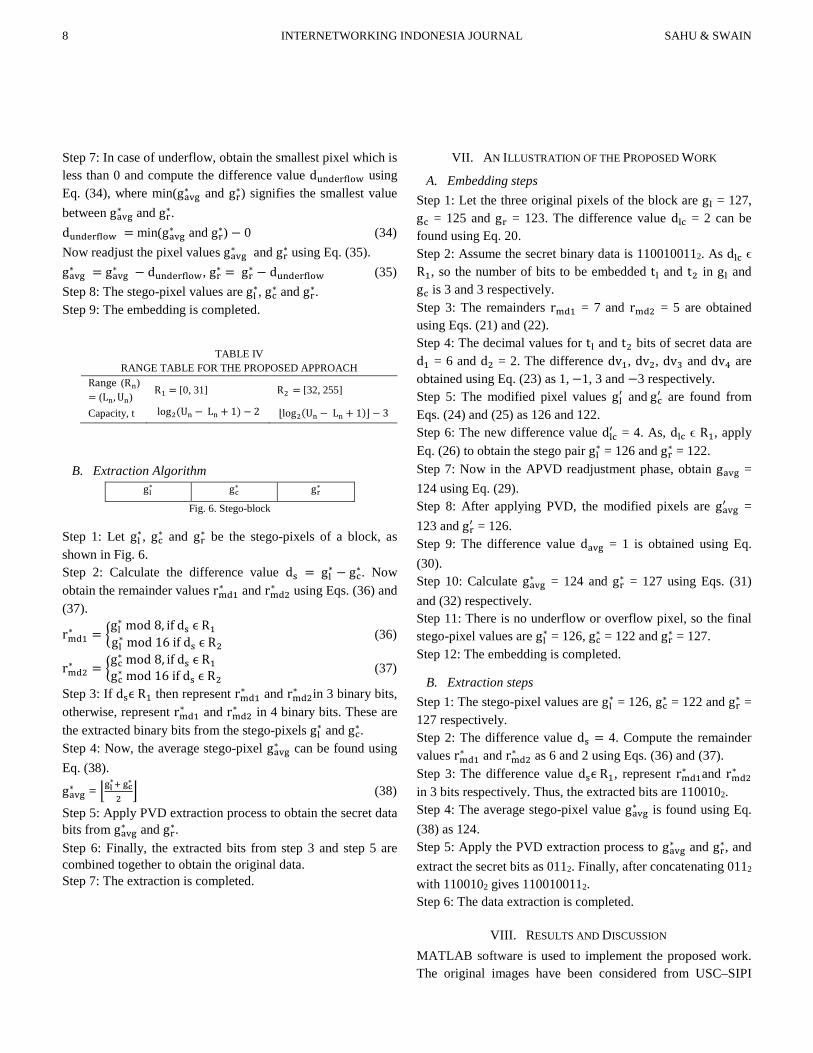
B. Extraction Algorithm gl∗ gc∗ gr∗
Fig. 6. Stego-block
Step 1: Let gl∗, gc∗ and gr∗ be the stego-pixels of a block, as shown in Fig. 6. Step 2: Calculate the difference value ds = gl∗ − gc∗. Now obtain the remainder values rmd1∗ and rmd2∗ using Eqs. (36) and (37).
rmd1∗ = �gl∗ mod 8, if ds ϵ R1 gl∗ mod 16 if ds ϵ R2
(36)
rmd2∗ = �gc∗ mod 8, if ds ϵ R1
gc∗ mod 16 if ds ϵ R2 (37)
Step 3: If dsϵ R1 then represent rmd1∗ and rmd2∗ in 3 binary bits, otherwise, represent rmd1∗ and rmd2∗ in 4 binary bits. These are the extracted binary bits from the stego-pixels gl∗ and gc∗. Step 4: Now, the average stego-pixel gavg∗ can be found using Eq. (38).
gavg∗ = �gl∗+ gc∗
2� (38)
Step 5: Apply PVD extraction process to obtain the secret data bits from gavg∗ and gr∗. Step 6: Finally, the extracted bits from step 3 and step 5 are combined together to obtain the original data. Step 7: The extraction is completed.
VII. AN ILLUSTRATION OF THE PROPOSED WORK
A. Embedding steps Step 1: Let the three original pixels of the block are gl = 127, gc = 125 and gr = 123. The difference value dlc = 2 can be found using Eq. 20. Step 2: Assume the secret binary data is 1100100112. As dlc ϵ R1, so the number of bits to be embedded tl and t2 in gl and gc is 3 and 3 respectively. Step 3: The remainders rmd1 = 7 and rmd2 = 5 are obtained using Eqs. (21) and (22). Step 4: The decimal values for tl and t2 bits of secret data are d1 = 6 and d2 = 2. The difference dv1, dv2, dv3 and dv4 are obtained using Eq. (23) as 1, −1, 3 and −3 respectively. Step 5: The modified pixel values gl′ and gc′ are found from Eqs. (24) and (25) as 126 and 122. Step 6: The new difference value dlc′ = 4. As, dlc ϵ R1, apply Eq. (26) to obtain the stego pair gl∗ = 126 and gr∗ = 122. Step 7: Now in the APVD readjustment phase, obtain gavg = 124 using Eq. (29). Step 8: After applying PVD, the modified pixels are gavg′ = 123 and gr′ = 126. Step 9: The difference value davg = 1 is obtained using Eq. (30). Step 10: Calculate gavg∗ = 124 and gr∗ = 127 using Eqs. (31) and (32) respectively. Step 11: There is no underflow or overflow pixel, so the final stego-pixel values are gl∗ = 126, gc∗ = 122 and gr∗ = 127. Step 12: The embedding is completed.
B. Extraction steps Step 1: The stego-pixel values are gl∗ = 126, gc∗ = 122 and gr∗ = 127 respectively. Step 2: The difference value ds = 4. Compute the remainder values rmd1∗ and rmd2∗ as 6 and 2 using Eqs. (36) and (37). Step 3: The difference value dsϵ R1, represent rmd1∗ and rmd2∗ in 3 bits respectively. Thus, the extracted bits are 1100102. Step 4: The average stego-pixel value gavg∗ is found using Eq. (38) as 124. Step 5: Apply the PVD extraction process to gavg∗ and gr∗, and extract the secret bits as 0112. Finally, after concatenating 0112 with 1100102 gives 1100100112. Step 6: The data extraction is completed.
VIII. RESULTS AND DISCUSSION MATLAB software is used to implement the proposed work. The original images have been considered from USC–SIPI
Vol. 10/No. 2 (2018) INTERNETWORKING INDONESIA JOURNAL 9
ISSN: 1942-9703 / CC BY-NC-ND
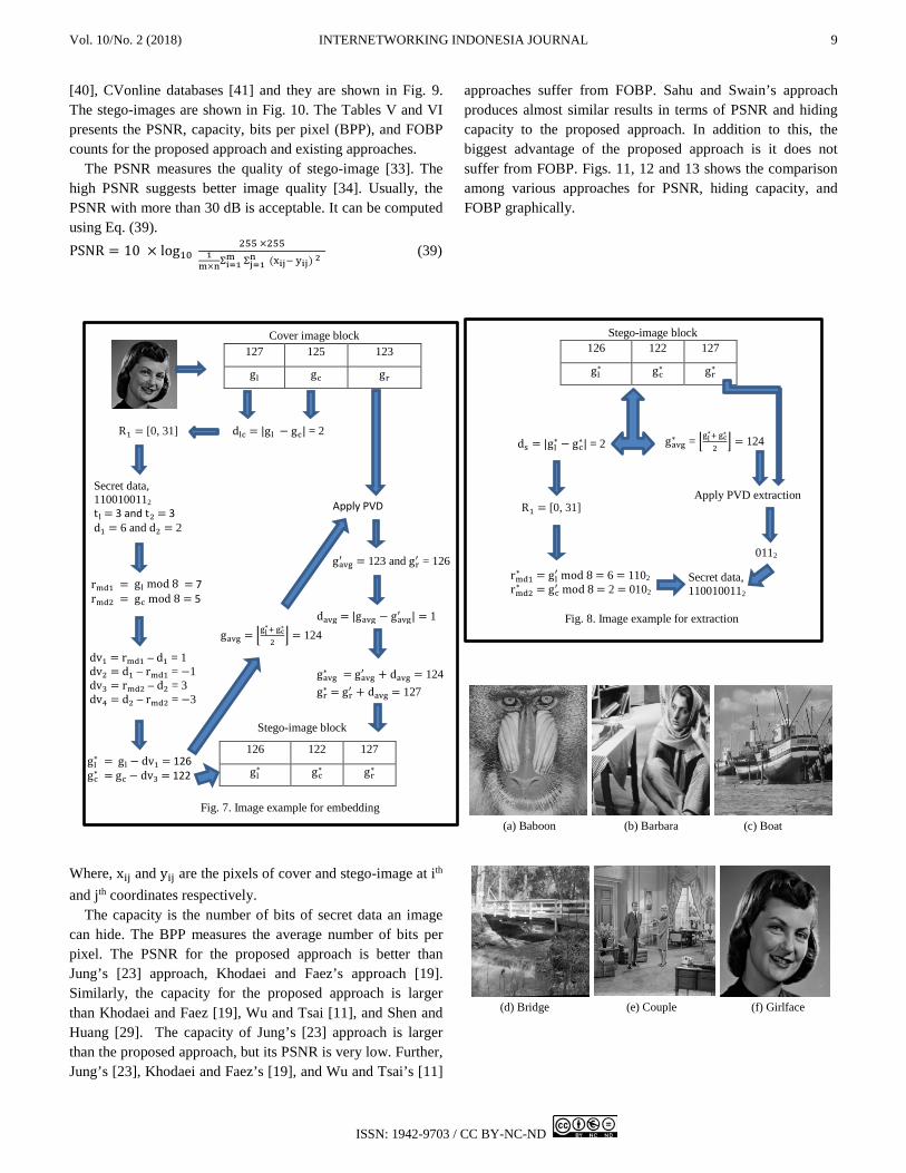
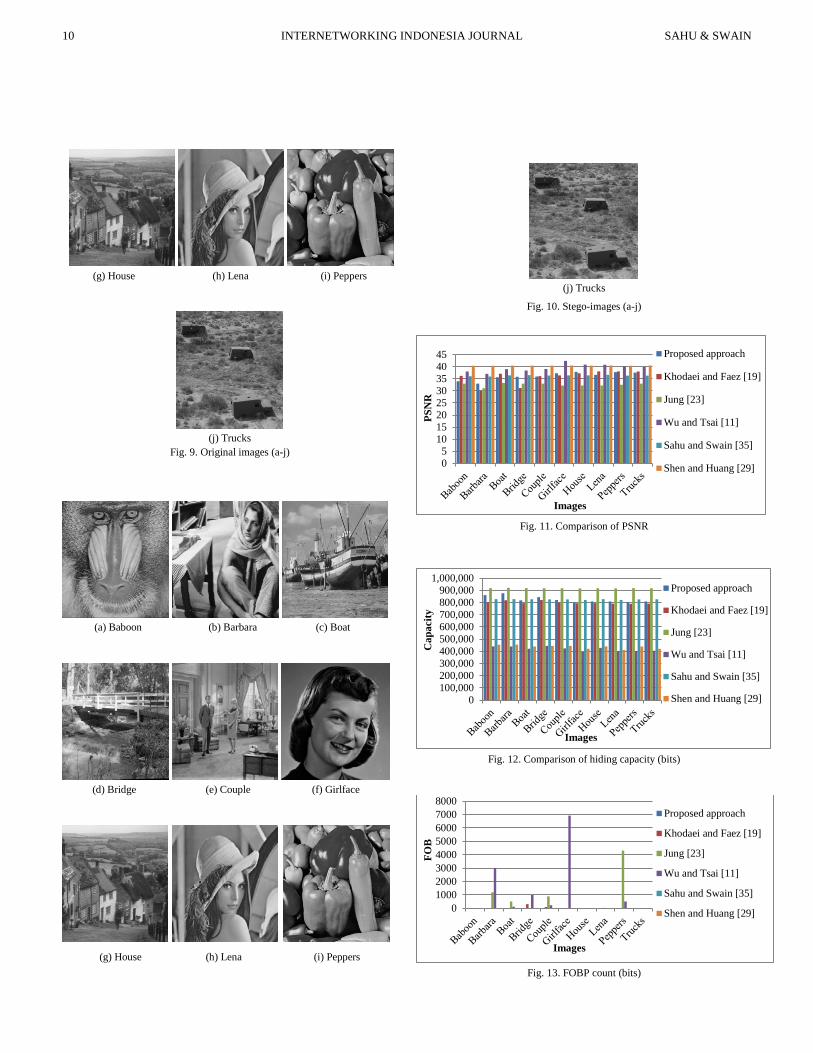
[40], CVonline databases [41] and they are shown in Fig. 9. The stego-images are shown in Fig. 10. The Tables V and VI presents the PSNR, capacity, bits per pixel (BPP), and FOBP counts for the proposed approach and existing approaches.
The PSNR measures the quality of stego-image [33]. The high PSNR suggests better image quality [34]. Usually, the PSNR with more than 30 dB is acceptable. It can be computed using Eq. (39). PSNR = 10 × log10 255 ×255
1m×nΣi=1
m Σj=1 n (xij− yij) 2
(39)
Where, xij and yij are the pixels of cover and stego-image at ith and jth coordinates respectively.
The capacity is the number of bits of secret data an image can hide. The BPP measures the average number of bits per pixel. The PSNR for the proposed approach is better than Jung’s [23] approach, Khodaei and Faez’s approach [19]. Similarly, the capacity for the proposed approach is larger than Khodaei and Faez [19], Wu and Tsai [11], and Shen and Huang [29]. The capacity of Jung’s [23] approach is larger than the proposed approach, but its PSNR is very low. Further, Jung’s [23], Khodaei and Faez’s [19], and Wu and Tsai’s [11]
approaches suffer from FOBP. Sahu and Swain’s approach produces almost similar results in terms of PSNR and hiding capacity to the proposed approach. In addition to this, the biggest advantage of the proposed approach is it does not suffer from FOBP. Figs. 11, 12 and 13 shows the comparison among various approaches for PSNR, hiding capacity, and FOBP graphically.
(a) Baboon (b) Barbara (c) Boat
(d) Bridge (e) Couple (f) Girlface
127 125 123
gl gc gr
126 122 127
gl∗ gc∗ gr∗
126 122 127
gl∗ gc∗ gr∗
0112
Secret data, 1100100112
gavg∗ = �gl∗+ gc∗
2� = 124 ds = |gl∗ − gc∗| = 2
rmd1∗ = gl′ mod 8 = 6 = 1102
rmd2∗ = gc′ mod 8 = 2 = 0102
R1 = [0, 31]
Apply PVD extraction
gavg′ = 123 and gr′ = 126
davg = |gavg − gavg′ | = 1
gl∗ = gl − dv1 = 126 gc∗ = gc − dv3 = 122
gavg = �gl∗+ gc∗
2� = 124
dv1 = rmd1 – d1 = 1 dv2 = d1 – rmd1 = −1 dv3 = rmd2 – d2 = 3 dv4 = d2 – rmd2 = −3
rmd1 = gl mod 8 = 7 rmd2 = gc mod 8 = 5
Secret data, 1100100112 tl = 3 and t2 = 3 d1 = 6 and d2 = 2
dlc = |gl − gc| = 2
R1 = [0, 31]
gavg∗ = gavg′ + davg = 124 gr∗ = gr′ + davg = 127
Apply PVD
Cover image block
Fig. 7. Image example for embedding
Fig. 8. Image example for extraction
Stego-image block
Stego-image block
10 INTERNETWORKING INDONESIA JOURNAL SAHU & SWAIN
(g) House (h) Lena (i) Peppers
(j) Trucks
Fig. 9. Original images (a-j)
(a) Baboon (b) Barbara (c) Boat
(d) Bridge (e) Couple (f) Girlface
(g) House (h) Lena (i) Peppers
(j) Trucks
Fig. 10. Stego-images (a-j)
Fig. 11. Comparison of PSNR
Fig. 12. Comparison of hiding capacity (bits)
Fig. 13. FOBP count (bits)
05
1015202530354045 Proposed approach
Khodaei and Faez [19]
Jung [23]
Wu and Tsai [11]
Sahu and Swain [35]
Shen and Huang [29]
PSN
R
Images
0100,000200,000300,000400,000500,000600,000700,000800,000900,000
1,000,000Proposed approach
Khodaei and Faez [19]
Jung [23]
Wu and Tsai [11]
Sahu and Swain [35]
Shen and Huang [29]
Cap
acity
Images
010002000300040005000600070008000
Proposed approach
Khodaei and Faez [19]
Jung [23]
Wu and Tsai [11]
Sahu and Swain [35]
Shen and Huang [29]
FOB
Images

Vol. 10/No. 2 (2018) INTERNETWORKING INDONESIA JOURNAL 11
ISSN: 1942-9703 / CC BY-NC-ND
TABLE V
RESULTS FOR THE PROPOSED APPROACH, KHODAEI AND FAEZ [19], AND JUNG [23]
Image (512*512) Proposed approach Khodaei and Faez [19] Jung [23]
PSNR Capacity BPP FOBP PSNR Capacity BPP FOBP PSNR Capacity BPP FOBP
Baboon 34.01 861,004 3.28 0 36.27 801,902 3.06 0 33.01 918,039 3.5 0
Barbara 32.99 876,879 3.35 0 30.03 819,540 3.13 0 31.12 919,293 3.51 1198
Boat 35.65 817,471 3.12 0 37.11 795,480 3.03 0 33.36 917,899 3.5 509
Bridge 35.83 843,513 3.22 0 31.21 820,398 3.13 312 33.02 917,039 3.5 0
Couple 35.97 820,286 3.13 0 36.09 799,026 3.05 98 33.03 917,040 3.5 893
Girlface 37.33 800,592 3.05 0 36.41 794,492 3.03 0 32.19 916,540 3.5 0
House 37.87 808,520 3.08 0 37.31 795,649 3.04 0 32.21 916,773 3.5 23
Lena 36.67 809,013 3.09 0 38.11 791,023 3.02 0 32.21 915,639 3.49 31
Peppers 37.73 804,236 3.07 0 38.06 790,006 3.01 0 32.53 918,987 3.51 4308
Trucks 37.57 809,032 3.09 0 38.02 791,039 3.02 0 33.03 917,204 3.5 0
Average 36.16 825,055 3.15 0 35.86 799,856 3.05 41 32.57 917,445 3.5 696.2
TABLE VI
RESULTS FOR WU AND TSAI [11], SAHU AND SWAIN’S PVDMF [35], AND SHEN AND HUANG [29]
Image (512*512) Wu and Tsai [11] Sahu and Swain [35] Shen and Huang [29]
PSNR Capacity BPP FOBP PSNR Capacity BPP FOBP PSNR Capacity BPP FOBP
Baboon 38.01 441,098 1.68 0 36.03 828,367 3.16 0 40.40 453,768 1.73 0
Barbara 37.04 438,949 1.67 3009 35.98 828,405 3.16 0 40.39 454,654 1.73 0
Boat 39.03 421,750 1.61 109 36.43 824,769 3.15 0 40.47 439,732 1.68 0
Bridge 38.45 444,675 1.7 996 36.52 825,404 3.15 0 40.50 444,349 1.70 0
Couple 39.09 423,549 1.62 230 36.31 825,498 3.15 0 40.49 444,287 1.69 0
Girlface 42.44 394,904 1.51 6918 36.39 820,009 3.13 0 40.51 421,389 1.61 0
House 40.88 427,490 1.63 0 36.32 826,776 3.16 0 40.47 441,310 1.68 0
Lena 40.78 402,365 1.53 0 36.51 820,609 3.13 0 40.52 410,879 1.57 0
Peppers 40.11 402,756 1.54 503 36.29 825,002 3.15 0 40.43 439,029 1.67 0
Trucks 39.94 403,467 1.54 0 36.22 824,403 3.16 0 40.51 420,302 1.60 0
Average 39.58 420,100 1.6 1177 36.30 824,924 3.15 0 40.46 436,970 1.67 0
A. Security check using RS analysis The attack resistance of the proposed approach has been verified using RS analysis. RS analysis is a statistical analysis which is basically implemented to identify the suspicious behaviour of the stego-image. Initially, the stego-pixels are categorized into three groups such as: (i) the regular group
with RM and R−M, (ii) the singular group with SM and S−M, and (iii) the unusable group. The regular ad singular groups are obtained using the discrimination function (DF). The X-axis and Y-axis represents the percentage of embedding capacity and the regular and singular groups.
Initially, ten stego-images at various embedding rate with an increment of 10% each is obtained. Finally, the plot can be drawn by considering the regular and singular groups. If we
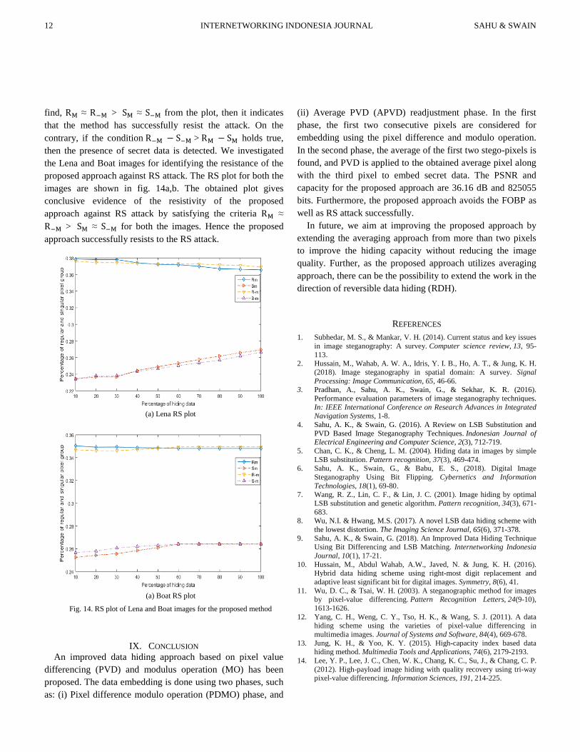
12 INTERNETWORKING INDONESIA JOURNAL SAHU & SWAIN find, RM ≈ R−M > SM ≈ S−M from the plot, then it indicates that the method has successfully resist the attack. On the contrary, if the condition R−M − S−M > RM − SM holds true, then the presence of secret data is detected. We investigated the Lena and Boat images for identifying the resistance of the proposed approach against RS attack. The RS plot for both the images are shown in fig. 14a,b. The obtained plot gives conclusive evidence of the resistivity of the proposed approach against RS attack by satisfying the criteria RM ≈ R−M > SM ≈ S−M for both the images. Hence the proposed approach successfully resists to the RS attack.
(a) Lena RS plot
(a) Boat RS plot
Fig. 14. RS plot of Lena and Boat images for the proposed method
IX. CONCLUSION An improved data hiding approach based on pixel value
differencing (PVD) and modulus operation (MO) has been proposed. The data embedding is done using two phases, such as: (i) Pixel difference modulo operation (PDMO) phase, and
(ii) Average PVD (APVD) readjustment phase. In the first phase, the first two consecutive pixels are considered for embedding using the pixel difference and modulo operation. In the second phase, the average of the first two stego-pixels is found, and PVD is applied to the obtained average pixel along with the third pixel to embed secret data. The PSNR and capacity for the proposed approach are 36.16 dB and 825055 bits. Furthermore, the proposed approach avoids the FOBP as well as RS attack successfully.
In future, we aim at improving the proposed approach by extending the averaging approach from more than two pixels to improve the hiding capacity without reducing the image quality. Further, as the proposed approach utilizes averaging approach, there can be the possibility to extend the work in the direction of reversible data hiding (RDH).
REFERENCES 1. Subhedar, M. S., & Mankar, V. H. (2014). Current status and key issues
in image steganography: A survey. Computer science review, 13, 95-113.
2. Hussain, M., Wahab, A. W. A., Idris, Y. I. B., Ho, A. T., & Jung, K. H. (2018). Image steganography in spatial domain: A survey. Signal Processing: Image Communication, 65, 46-66.
3. Pradhan, A., Sahu, A. K., Swain, G., & Sekhar, K. R. (2016). Performance evaluation parameters of image steganography techniques. In: IEEE International Conference on Research Advances in Integrated Navigation Systems, 1-8.
4. Sahu, A. K., & Swain, G. (2016). A Review on LSB Substitution and PVD Based Image Steganography Techniques. Indonesian Journal of Electrical Engineering and Computer Science, 2(3), 712-719.
5. Chan, C. K., & Cheng, L. M. (2004). Hiding data in images by simple LSB substitution. Pattern recognition, 37(3), 469-474.
6. Sahu, A. K., Swain, G., & Babu, E. S., (2018). Digital Image Steganography Using Bit Flipping. Cybernetics and Information Technologies, 18(1), 69-80.
7. Wang, R. Z., Lin, C. F., & Lin, J. C. (2001). Image hiding by optimal LSB substitution and genetic algorithm. Pattern recognition, 34(3), 671-683.
8. Wu, N.I. & Hwang, M.S. (2017). A novel LSB data hiding scheme with the lowest distortion. The Imaging Science Journal, 65(6), 371-378.
9. Sahu, A. K., & Swain, G. (2018). An Improved Data Hiding Technique Using Bit Differencing and LSB Matching. Internetworking Indonesia Journal, 10(1), 17-21.
10. Hussain, M., Abdul Wahab, A.W., Javed, N. & Jung, K. H. (2016). Hybrid data hiding scheme using right-most digit replacement and adaptive least significant bit for digital images. Symmetry, 8(6), 41.
11. Wu, D. C., & Tsai, W. H. (2003). A steganographic method for images by pixel-value differencing. Pattern Recognition Letters, 24(9-10), 1613-1626.
12. Yang, C. H., Weng, C. Y., Tso, H. K., & Wang, S. J. (2011). A data hiding scheme using the varieties of pixel-value differencing in multimedia images. Journal of Systems and Software, 84(4), 669-678.
13. Jung, K. H., & Yoo, K. Y. (2015). High-capacity index based data hiding method. Multimedia Tools and Applications, 74(6), 2179-2193.
14. Lee, Y. P., Lee, J. C., Chen, W. K., Chang, K. C., Su, J., & Chang, C. P. (2012). High-payload image hiding with quality recovery using tri-way pixel-value differencing. Information Sciences, 191, 214-225.

Vol. 10/No. 2 (2018) INTERNETWORKING INDONESIA JOURNAL 13
ISSN: 1942-9703 / CC BY-NC-ND
15. Swain, G. (2015). Adaptive pixel value differencing steganography using both vertical and horizontal edges. Multimedia Tools and Applications, 75(21), 13541-13556.
16. Hussain, M., Wahab, A. W. A., Ho, A. T., Javed, N., & Jung, K. H. (2017). A data hiding scheme using parity-bit pixel value differencing and improved rightmost digit replacement. Signal Processing: Image Communication, 50, 44-57.
17. Hameed, M. A., Aly, S., & Hassaballah, M. (2017). An efficient data hiding method based on adaptive directional pixel value differencing (ADPVD). Multimedia Tools and Applications, 77(12), 14705-14723.
18. Wu, H. C., Wu, N. I., Tsai, C. S., & Hwang, M. S. (2005). Image steganographic scheme based on pixel-value differencing and LSB replacement methods. IEE Proceedings-Vision, Image and Signal Processing, 152(5).
19. Khodaei, M., & Faez, K. (2012). New adaptive steganographic method using least-significant-bit substitution and pixel-value differencing. IET Image processing, 6(6), 677-686.
20. Khodaei, M., Sadeghi Bigham, B., & Faez, K., (2016). Adaptive Data Hiding, Using Pixel-Value-Differencing and LSB Substitution. Cybernetics and Systems, 47(8), 617-628.
21. Swain, G. (2018). Adaptive and Non-adaptive PVD Steganography Using Overlapped Pixel Blocks. Arabian Journal for Science and Engineering, 1-14. (Article in press). https://doi.org/10.1007/s13369-018-3163-9
22. Liao, X., Wen, Q. Y., & Zhang, J. (2011). A steganographic method for digital images with four-pixel differencing and modified LSB substitution. Journal of Visual Communication and Image Representation, 22(1), 1-8.
23. Jung, K. H. (2018). Data hiding scheme improving embedding capacity using mixed PVD and LSB on bit plane. Journal of Real-Time Image Processing, 14(1), 127-136.
24. Swain, G. (2018). Very High Capacity Image Steganography Technique Using Quotient Value Differencing and LSB Substitution. Arabian Journal for Science and Engineering, (Article in press). https://doi.org/10.1007/s13369-018-3372-2
25. Wang, C. M., Wu, N. I., Tsai, C. S., & Hwang, M. S. (2008). A high quality steganographic method with pixel-value differencing and modulus function. Journal of Systems and Software, 81(1), 150-158.
26. Joo, J. C., Lee, H. Y., & Lee, H. K. (2010). Improved steganographic method preserving pixel-value differencing histogram with modulus function. EURASIP Journal on Advances in Signal Processing, 2010(1), 249826.
27. Maleki, N., Jalali, M. & Jahan, M. V. (2014). Adaptive and non-adaptive data hiding methods for grayscale images based on modulus function. Egyptian Informatics Journal, 15(2), 115-127.
28. Liao, X., Wen, Q., & Zhang, J. (2013). Improving the Adaptive Steganographic methods Based on Modulus Function. IEICE Transactions on Fundamentals of Electronics, Communications and Computer Sciences, 96(12), 2731-2734.
29. Shen, S., Huang, L., & Tian, Q. (2015). A novel data hiding for color images based on pixel value difference and modulus function. Multimedia Tools and Applications, 74(3), 707-728.
30. Liao, X., Wen, Q. Y., Zhao, Z. L., & Zhang, J. (2012). A novel steganographic method with four-pixel differencing and modulus function. Fundamenta Informaticae, 118(3), 281-289.
31. Thien, C. C., & Lin, J. C. (2003). A simple and high-hiding capacity method for hiding digit-by-digit data in images based on modulus function. Pattern recognition, 36(12), 2875-2881.
32. Lee, C. F., & Chen, H. L. (2010). A novel data hiding scheme based on modulus function. Journal of Systems and Software, 83(5), 832-843.
33. Liao, X., Guo, S., Yin, J., Wang, H., Li, X., & Sangaiah, A. K. (2017). New cubic reference table based image steganography. Multimedia Tools and Applications, 1-18. DOI 10.1007/s11042-017-4946-9.
34. Liao, X., Qin, Z., & Ding, L. (2017). Data embedding in digital images using critical functions. Signal Processing: Image Communication, 58, 146-156.
35. Sahu, A. K., & Swain, G. (2018). Pixel Overlapping Image Steganography Using PVD and Modulus Function. 3D Research, 9(3), 1-14. https://doi.org/10. 1007/s13319-018-0188-5.
36. Sahu, A.K., & Swain, G. (2017). Information Hiding Using Group of Bits Substitution. International Journal on Communications Antenna and Propagation, 7(2), 162-167.
37. Sahu, A.K., & Swain, G. (2018). Data hiding using adaptive LSB and PVD technique resisting PDH and RS analysis. International Journal of Electronic Security and Digital Forensics. (In press).
38. Sahu, A. K., & Swain, G. (2019). A Novel n-Rightmost Bit Replacement Image Steganography Technique. 3D Research, 10(1), 1-18.
39. Balasubramanian, C., Selvakumar, S., & Geetha, S. (2014). High payload image steganography with reduced distortion using octonary pixel pairing scheme. Multimedia tools and applications, 73(3), 2223-2245.
40. USC-SIPI Image Database. [Online]. Available: http://sipi.usc.edu/database/database.php?volume=misc.
41. http://homepages.inf.ed.ac.uk/rbf/CVonline/Imagedbase.htm. Mr. Aditya Kumar Sahu was born and brought up in the state of Odisha, India. He has completed B.Tech (I.T) degree in 2007 and M.Tech (CS) degree in 2011. Currently, he is pursuing Ph.D. (CSE) in Koneru Lakshmaiah Education Foundation, Vaddeswaram, Guntur, Andhra Pradesh, India. He is working as an Assistant Professor in the Department of Computer Science and Engineering, GMRIT, Rajam, Andhra Pradesh, India. He has more than 10 years of teaching experience and published more than 15 research articles in international journals and conferences. His research interests are image steganography and network security. He is a life member of CSI. Dr. Gandharba Swain was born in the state of Odisha, located at eastern part of India. He has obtained M.Tech (CSE) degree from NIT, Rourkela, in 2004 and PhD (CSE) degree from SOA Deemed to be University, Bhubaneswar in 2014. He is working as a Professor in the Department of Computer Science and Engineering, Koneru Lakshmaiah Education Foundation, Vaddeswaram, Guntur, and Andhra Pradesh, India. He has more than 19 years of teaching experience and more than 9 years of research experience. He has authored two text books, published more than 50 research articles in international journals and conferences in the areas of security, image processing and Image Steganography. Some of his papers are published by journals of reputed publishers like Elsevier, Springer, Inderscience, Hindawi and Wiley. He is a member of CSI, ISTE, IAENG, IACSIT and ACM.