Digital II Pressure Control System Model 64135 -...
18
Model 64135 Digital II Pressure Control System Applicable additional manuals: NONE Aerospace Group Conveyance Systems Divison Carter ® Brand Ground Fueling Equipment UM64135 User's Manual October 7, 2002 User Manual
Transcript of Digital II Pressure Control System Model 64135 -...

Model 64135
Digital II Pressure Control System
Applicable additional manuals:
NONE
Aerospace Group Conveyance Systems Divison Carter® Brand Ground Fueling Equipment
UM64135 User's ManualOctober 7, 2002
User Manual

Table of Contents
1. Definitions 2. General Information 3. Pulsers 4. Navigating the Menu System 5. Setup 6. Calibration 7. Configuration 8. Trouble Shooting and Error Codes

1. Definitions Reset: As part of the instructions you may be asked to reset the unit. This may
be accomplished by turning the power off to the control module and then turning it back on. On most refueling equipment the power will be turned off to the control module when the refueling equipment is returned to the road condition. For example all of the nozzles stowed, the pump disengaged and the brakes released.
System Reset or Power on Reset:
It is possible to restore the system back to the factory or default setup, calibration and configuration settings. With the hand held unit connected to the control module and the rotary switch in the “Modify” position push the “UP” and “DOWN” buttons simultaneously. This will ERASE ALL PREVIOUS USER SETTINGS, and replace them with the original factory (default) setting. While this procedure will bring the unit back to a known baseline, it is NOT recommended that this unit be used to service aircraft, until the “Setup”, “Calibration” and “Configuration” procedures are once again performed to completion.
2. General Information Your new Digital II Control Module should include the following items,
1. Digital II “Control Module” 2. “Hand-Held” unit used to perform set up and calibration 3. Cable to connect the “Hand-Held” device to the “Control Module” 4. “Nozzle Transducer” assembly
The items listed above are required to make any modification to the SETUP, CALIBRATION or CONFIGURATION. All of the items will be required for normal operations .. .
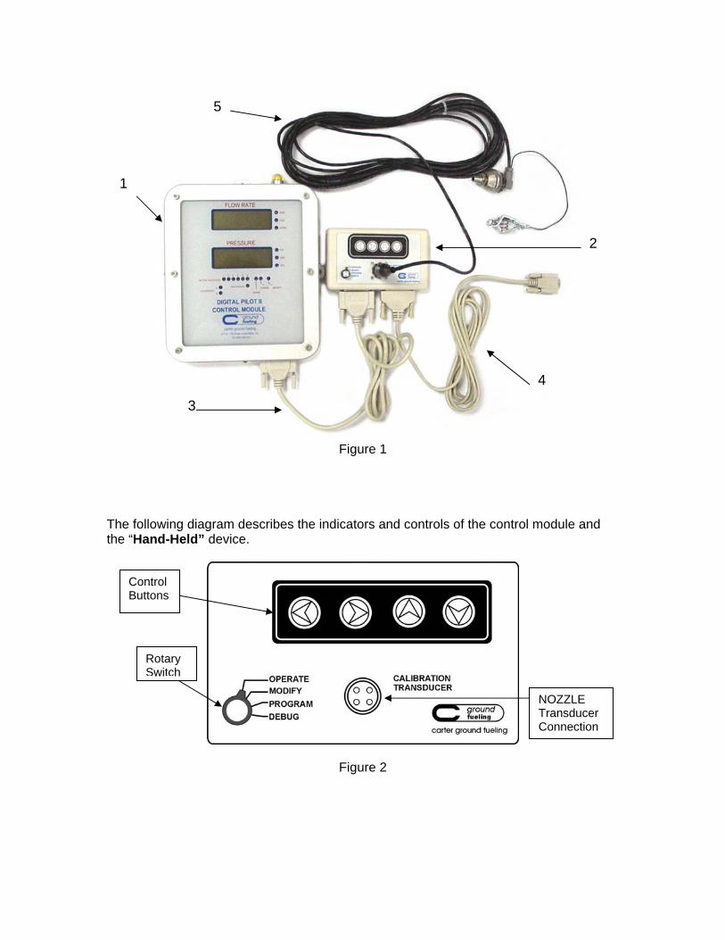
Figure 1
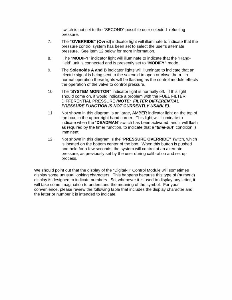
The following diagram describes the indicators and controls of the control module and the “Hand-Held” device.
Figure 2
Rotary Switch
NOZZLE Transducer Connection
Control Buttons
1
2
3
4
5

Figure 3
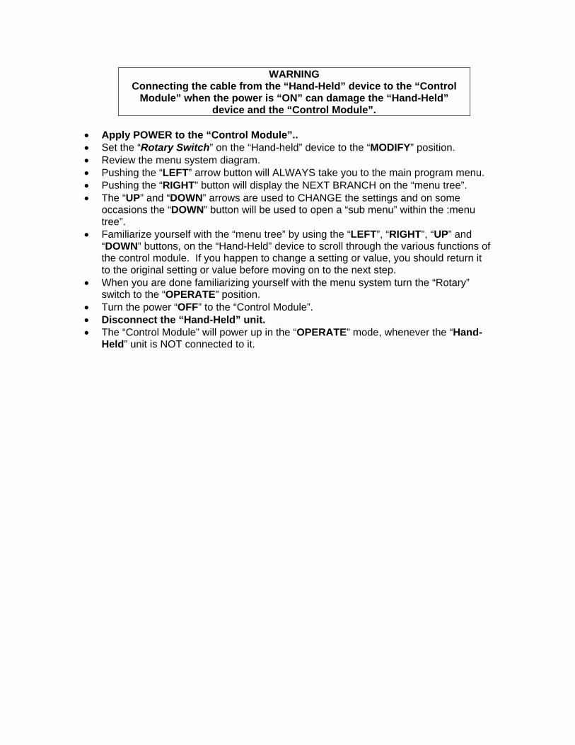
1. “FLOW RATE” display will indicate the rate of flow of the product.
2. The indicator lights to the right of the “FLOW RATE” display will illuminate to indicate the “UNIT-OF-MEASURE” at which the flow rate is being displayed.
3. “NOZZLE PRESURE” will indicate the pressure that the product is being dispensed.
4. The indicator lights to the right of the “NOZZLE PRESSURE” display will illuminate to indicate the “UNIT-OF-MEASURE” that pressure is being displayed.
5. “ACTIVE NOZZLE” indicator lights 1-6 will illuminate to indicate the nozzle or nozzles that are being used or that are not currently stowed.
6. The “NORMAL” (Norm) indicator light will illuminate to indicate that the power is “ON” to the control module and that the “PRESURE OVERRIDE”
switch is not set to the “SECOND” possible user selected refueling pressure.
7. The “OVERRIDE” (Ovrrd) indicator light will illuminate to indicate that the pressure control system has been set to select the user’s alternate pressure. See item 12 below for more information.
8. The “MODIFY” indicator light will illuminate to indicate that the “Hand-Held” unit is connected and is presently set to “MODIFY” mode.
9. The Solenoids A and B indicator lights will illuminate to indicate that an electric signal is being sent to the solenoid to open or close them. In normal operation these lights will be flashing as the control module effects the operation of the valve to control pressure.
10. The “SYSTEM MONITOR” indicator light is normally off. If this light should come on, it would indicate a problem with the FUEL FILTER DIFFERENTIAL PRESSURE (NOTE: FILTER DIFFERENTIAL PRESSURE FUNCTION IS NOT CURRENTLY USABLE).
11. Not shown in this diagram is an large, AMBER indicator light on the top of the box, in the upper right hand corner. This light will illuminate to indicate when the “DEADMAN” switch has been activated, and it will flash as required by the timer function, to indicate that a “time-out” condition is imminent.
12. Not shown in this diagram is the “PRESSURE OVERRIDE” switch, which is located on the bottom center of the box. When this button is pushed and held for a few seconds, the system will control at an alternate pressure, as previously set by the user during calibration and set up process.
We should point out that the display of the “Digital-II” Control Module will sometimes display some unusual looking characters. This happens because this type of (numeric) display is designed to indicate numbers. So, whenever it is used to display any letter, it will take some imagination to understand the meaning of the symbol. For your convenience, please review the following table that includes the display character and the letter or number it is intended to indicate.

3. Pulsers: The Digital II Pressure Control System provides PRESSURE COMPENSATED FLOW. To accomplish this, it compares flow rate to sensed pressure and performs a calculation to determine the maximum flow rate allowable, while remaining within the pressure range permitted. To provide a “FLOW RATE” signal to the Digital System a “Pulse Transmitter” head must be attached to the “FLOW METER”. While this component is NOT available from Carter Ground Fueling Division, we recommend the use of a Veeder-Root “100->1 Pulse Generator" p/n: 767181 327 along with it's required mounting kit p/n: 0370020 009. 4. Navigating the Menu System: To navigate the menu tree system: • Assure that power to the control module is now “OFF” • When the power is “OFF”, both displays will be blank, and all indicator lights will be
off. (Refer to Reset in section 1 for additional information). • Connect the Cable (Item 3 as indicated in figure 1) between the “Hand-Held” device
and the “Control Module”.
WARNING Connecting the cable from the “Hand-Held” device to the “Control
Module” when the power is “ON” can damage the “Hand-Held” device and the “Control Module”.
• Apply POWER to the “Control Module”.. • Set the “Rotary Switch” on the “Hand-held” device to the “MODIFY” position. • Review the menu system diagram. • Pushing the “LEFT” arrow button will ALWAYS take you to the main program menu. • Pushing the “RIGHT” button will display the NEXT BRANCH on the “menu tree”. • The “UP” and “DOWN” arrows are used to CHANGE the settings and on some
occasions the “DOWN” button will be used to open a “sub menu” within the :menu tree”.
• Familiarize yourself with the “menu tree” by using the “LEFT”, “RIGHT”, “UP” and “DOWN” buttons, on the “Hand-Held” device to scroll through the various functions of the control module. If you happen to change a setting or value, you should return it to the original setting or value before moving on to the next step.
• When you are done familiarizing yourself with the menu system turn the “Rotary” switch to the “OPERATE” position.
• Turn the power “OFF” to the “Control Module”. • Disconnect the “Hand-Held” unit. • The “Control Module” will power up in the “OPERATE” mode, whenever the “Hand-
Held” unit is NOT connected to it.
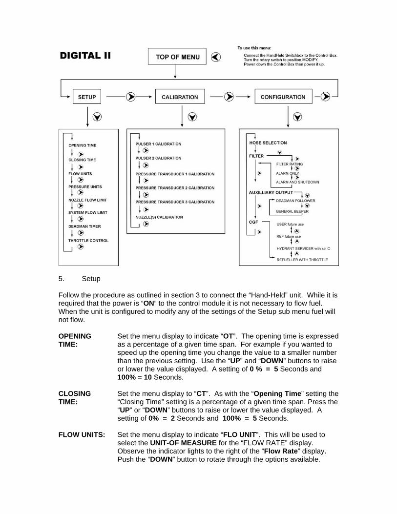
5. Setup Follow the procedure as outlined in section 3 to connect the “Hand-Held” unit. While it is required that the power is “ON” to the control module it is not necessary to flow fuel. When the unit is configured to modify any of the settings of the Setup sub menu fuel will not flow. OPENING TIME:
Set the menu display to indicate “OT”. The opening time is expressed as a percentage of a given time span. For example if you wanted to speed up the opening time you change the value to a smaller number than the previous setting. Use the “UP” and “DOWN” buttons to raise or lower the value displayed. A setting of 0 % = 5 Seconds and 100% = 10 Seconds.
CLOSING TIME:
Set the menu display to “CT”. As with the “Opening Time” setting the “Closing Time” setting is a percentage of a given time span. Press the “UP” or “DOWN” buttons to raise or lower the value displayed. A setting of 0% = 2 Seconds and 100% = 5 Seconds.
FLOW UNITS: Set the menu display to indicate “FLO UNIT”. This will be used to select the UNIT-OF MEASURE for the “FLOW RATE” display. Observe the indicator lights to the right of the “Flow Rate” display. Push the “DOWN” button to rotate through the options available.

After you have selected the unit of measure, press the “RIGHT” button to proceed to the next step.
PRESSURE UNIT:
Set the menu display to indicate “PRES UNIT”. This will be used to select the UNIT-OF-MEASURE for the pressure display. Observe the indicator lights to the “RIGHT” of the Pressure display. Push the “DOWN” button to rotate through the options available. After you have selected the unit of measure, press the “RIGHT” button to proceed to the next step.
Nozzle Flow Limit:
Set the menu display to indicate “FL”. This will be used to set the “FLOW LIMIT” for EACH HOSE or COMBINATION OF HOSES. Set the flow limit for EACH of 6 hoses. Use the “UP” and “DOWN” buttons to set the MAXIMUM FLOW LIMIT for each hose that is being used, if so desired. It is possible to use hoses in combination. For example, it is very common to use TWO deck hoses at the same time. When setting the “Flow Limit” for these hoses, you would set each hose at one half the desired “flow rate” of the combination of the two hoses. Also, each of the hoses will be setup to the SAME “Nozzle Pressure” control value.
NOTE: When setting the “NOZZLE FLOW LIMIT”, only the nozzle that is being set should be
removed from it’s interlock. ALL OTHER NOZZLES should be stowed in their respective interlocks. If more than one nozzle is removed from an interlock, BOTH DISPLAYS WILL GO BLANK, and no other modifications will be allowed until the
errant nozzle is stowed.
SYSTEM FLOW LIMIT:
Set the menu display to indicate “SFL”. This will be used to set the CUMULATIVE FLOW LIMIT for the unit. This flow limit will govern ALL other flow limits. During fueling, the system will use the LOWEST of “SYSTEM FLOW LIMIT” and the “NOZZLE FLOW LIMIT” for the particular nozzle in use.
DEADMAN TIMER:
Set the menu display to indicate “DT”. This will be used to turn on and set the “DEADMAN TIMER FUNCTION”. Use the “UP” and “DOWN” buttons to set the number of minutes that the system will dispense fuel, before the operator will be required to “cycle” the “DEADMAN” switch. Set the display to ZERO to TURN “OFF” this Timer function. We recommend that the timer function be turned “OFF”, if the vehicle is equipped with an “OVERWING” nozzle.
THROTTLE CONTROL:
The menu will only display this option if the configuration has been set to “REF.T” or “Refueler With Throttle”. (See section 6) Set the menu indicator to display “THR”. Press the “UP” or “DOWN” button to set the trigger point which specifies the “flow rate” at which the control module will activate the “Throttle Advance” on the vehicle. Press the “LEFT” button to return to the main menu.
6. Calibration For this procedure it is required that the re-fueling equipment be set up to either re-circulate fuel, or to flow fuel through a test stand. Press the “RIGHT” button until “SYST CAL” is indicated on the display. Press the “DOWN” button to enter this sub menu. Pulser 1 Calibration:
Set the menu display to indicate “PLSR CAL 1”. For units with two meters select the nozzle connected to the meter with “Pulser #1”. Activate the “DEADMAN” switch to establish fuel flow. Using a stop watch, calculate the flow rate as indicated by the meter register. Use the “UP” and “DOWN” buttons to adjust the rate being displayed, to match actual flow rate as it was calculated.
Pulser 2 Calibration:
Most equipment will NOT have a SECOND meter or pulser. For those that do set the menu display to indicate “PLSR CAL 2”. Stow the nozzle that was used in the previous step and select the nozzles connected to the meter with pulser 2. Squeeze the deadman to establish a flow of product. Using a stop watch, calculate the flow rate as indicated by the meter register. Use the “UP” and “DOWN” buttons to adjust the rate being displayed, to match actual flow rate as it was calculated.
Note: While we do recommend a specific “Pulser” for the meter the unit will accept ANY pulse rate from: 10 100 Pulses-Per-Gallon.
The purpose of the next two steps in this procedure is to calibrate the “VEHICLE Transducer” and the “NOZZLE Transducer” so that the control module can correctly interpret the signal. It will be necessary to apply a KNOWN pressure to both the “VEHICLE mounted Transducer” and to the “NOZZLE Transducer”. A mechanical gauge installed adjacent to the transducer will be required. An acceptable pressure range is 20 75 PSI. “Sys. Xducer” is the “VEHICLE Mounted Transducer” and is connected permanently to Terminals# 11 13 inside the Control Module. Connect the “NOZZLE Transducer” to the “Hand-Held” unit, before proceeding to the next step.
NOTE: Applying a KNOWN pressure to both transducers can be accomplished in several
different ways. The simplest way to do this on a re-fueler, would be to lock up pressure in the system. To accomplish this, return the rotary switch to the “OPERATE” mode. With the unit setup to re-circulate fuel, activate the “DEADMAN” switch, and establish a flow of fuel. Close the isolation valve for the re-circulation adapter. When this valve is
closed, release the “DEADMAN” switch, and ensure that the pressure at the mechanical gauge adjacent to the transducer reads between 50 and 70 PSI for this “trapped”
pressure.
Pressure Transducer 1 Calibration:
Set the menu display to indicate “PT1”. Apply a KNOWN amount of pressure to the “VEHICLE MOUNTED TRANSDUCER”. ( If the display indicates a NEGATIVE pressure, please see the not below and Section 8.4). Use the “UP” and “DOWN” buttons to adjust the value on the display to equal that of the mechanical gauge.

Pressure Transducer 2 Calibration:
Set the menu display to indicate “PT2”. Apply a KNOWN amount of pressure to the “NOZZLE Transducer”. If the display indicates a NEGATIVE pressure, please see the note below, and Section 8.4. Use the “UP” and “DOWN” buttons adjust the value on the display to equal that of the mechanical gauge.
Pressure Transducer 3 Calibration:
This is for future use. Push the “RIGHT” button to go to the next item on the menu. (NOTE: “Transducer 3” IS NOT CURRENTLY USABLE).
NOTE: When “calibrating” Pressure Transducers 1,2 or 3, ACTIVATING THE “DEADMAN” will NOT CAUSE FUEL TO FLOW. This is why you MUST TRAP suitable pressure
first. Additionally, a NEGATIVE pressure reading USUALLY indicates that the
Transducer being calibrated has a faulty connection or is defective. See Trouble Shooting section 8.4.
NOZZLE CONTROL PRESSURE SETTING:
This step is used to set the desired “CONTROL PRESSURE” at which a nozzle will flow fuel. This procedure MUST be completed for EACH NOZZLE used. Remove the nozzle you wish to program, and connect it to “re-circulate” fuel, or to a test stand to FLOW fuel. If the NOZZLE is equipped with a “HOSE END CONTROL VALVE” (HECV), you MUST BLOCK THE REGULATOR IN THE OPEN POSITION. This can be easily accomplished with the 61656 “Block-Out” (or similar) device. The “NOZZLE Transducer” that was used in the previous step MUST remain connected. The display will scroll through a message that will ask you to press the “DOWN” button to begin calibration (“TO CAL PRES PUSH DN BTN”). Activate the “DEADMAN” switch and then press the “DOWN” button. The remainder of the process for this step is similar to that of “Digital-1”. Just establish a stable flow of fuel, and then SLOWLY throttle the valve down stream of the nozzle, to CREATE THE DESIRED BACK PRESSURE that you would like the system to FUEL THE AIRCRAFT AT, as indicated on the “Control Module” display. When the pressure is stable, at the desired fueling pressure, just release the “DEADMAN” switch to SET THIS NOZZLE PRESSURE as your desired fuel delivery nozzle pressure. The display will indicate “PSET” and show the pressure at which this hose will control flow during aircraft fueling. Now, rotate the “Rotary” Switch on the “Hand-Held” unit to the “OPERATE” position to lock in this pressure value. This procedure MUST be done for EACH HOSE that will be controlled by this system. This will also allow you to set a DIFFERENT pressure for each hose, if you so desire.. For example you could set the pressure for an “Overwing Hose” lower than the other hoses so that the nozzle will open more easily. After you have completed this step, push the “LEFT” button to return to “SETUP” on the main menu tree. Push the “RIGHT” button TWICE to get to

“CONFIGURATION” menu and the “DOWN” button to enter this “sub menu”.
7 Configuration Hose Assignment To Pulsers:
This step is used to ASSIGN the available hoses to a “PULSER”. If ONLY ONE PULSER IS USED ON YOUR SYSTEM, DO NOT DO THIS STEP. (Factory settings ALREADY assign ALL hoses to Pulser# 1). To assign any hoses to “Pulser# 1”, set the menu display to indicate “HSET”. Remove ALL needed nozzles from their holders together, then Activate the “DEADMAN” switch, and hold it for 15 seconds, then release it. The nozzle indicator lights that remain illuminated are now assigned to “Pulser# 1”. Any Nozzle Indicator Lights” that are turned off, are now assigned to “Pulser# 2”and so CANNOT be used at all..! (NOTE: Pulser #2 is NOT currently supported..so please DO NOT ATTEMPT TO ASSIGN ANY HOSES TO IT!)
Filter: The filter functions of the “Digital-II” Control System are not currently functional. Please proceed to the next step.
Auxiliary Output:
Your selection here will determine the operation of the “Auxiliary Output” (this is the equivalent of terminal 18 on “Digital-1”). On this system it is Terminal# 36. When active, this pin will provide the GROUND to complete the circuit for some other device. There will not be ANY voltage output from this terminal. You have two options. The first choice is “D.FOL”, where “Aux. Output” will “follow” the operation of the “DEADMAN” switch. (ie: When the “DEADMAN” switch is activated, the “Auxiliary Output” will immediately provide a ground signal, to operate some other device of your choosing. The SECOND choice is “D.BEP”. This “General Beeper” will provide a PULSING ground signal at Terminal# 36, whenever the “Deadman Timer” function begins to “flash” it’s 30-seconds to “Timeout” warning status. This “pulsing signal” will be active when the “Deadman Timer” function is selected, and will only provide a signal for the last thirty seconds of the timer cycle. The pulse rate is about the same as the Amber indicator light on the Control module. This signal could be connected to an audible device or a light to provide an indication to the operator that the “Deadman Timer” MUST be recycled. To select one of these options set the menu display to indicate “Auxiliary Output” (A.OUT). Push the “DOWN” button to cycle through the two options. Choose “D.FOL” to follow the operation of the “Deadman” switch or “D.BEP” to indicate the last thirty seconds of the timer cycle. When you have made your selection, push the “RIGHT” button to proceed to the next step. The load on Terminal# 36 should be limited to 28 Vdc with a MAXIMUM of 2 Amps of load current.
Configuration: The heading for this sub menu is also configuration and will be displayed as “SYST CONF”. This step will be indicated on the display
as “CFG=”. Set the menu display to “CFG=”. Push the “UP” and “DOWN” button to select the type of equipment that the “Digital-II” Control System is part of. There are four choices, two of which are for future use. The remaining two are “REF.T” for Refueler with throttle, or “HYDR” for Hydrant Dispenser. If you have a Refueler and elected not to use the throttle option, you must select “REF”. The system will function normally without using the throttle function.
Beacon (28VDC @ 2 Amps.):
This pin is Terminal# 35, and simply provides a ground signal, whenever the Amber indicator light one the Control Module is Lit. Consequently, it can be used to remotely operate a user provided “Deadman” Status indicator light.
The diagram (overleaf) shows messages that you can expect to see on the display:

8. Trouble Shooting and Error Codes: 8.1 Initial Display Message: Whenever power is turned “ON” to the “Control Module”, it will momentarily display the software version. For example “C1.01”. If this does NOT occur, you should reset the unit ( see note below). If this does NOT correct the problem you should contact the

manufacturer that assembled the refueling equipment, your local Carter Ground Fueling distributor or Carter Ground Fueling. Reset: As part of the instructions you may be asked to RESET this unit. This
may be accomplished by turning the power “OFF” to the control module and then turning it back on. On most refueling equipment, the power will be turned “OFF” to the control module when the refueling equipment is returned to the road condition. Example: ALL Nozzles are stowed, Pump is disengaged and Brakes are released.
System Reset or Power on Reset:
It is possible to restore the system back to the factory or default . With the “Hand-Held” unit connected to the “Control Module” and the Rotary switch in the “MODIFY” position, push the “UP” and “DOWN” buttons simultaneously. This will ERASE all previous settings and replace them with the original factory setting. While this procedure will bring the unit back to a known baseline, it is NOT recommended that this unit be used to service aircraft until the “Setup”, “Calibration” and “Configuration” procedures are performed to completion.
8.2 Error Codes: The “Digital-II Control Module” includes some self diagnosing functions. When the unit encounters a problem it will display an error code. These error codes are as follows, E1.1 Processor has encountered an “Invalid Instruction”. (OPERATONS STOP..!) E1.2 “Interrupt” from an unassigned or reserved area”. (OPERATONS STOP..!) E1.3 An “unknown Interrupt” has occurred. (OPERATONS STOP..!) E1.4 A “Clock Failure” has occurred. ”. (OPERATONS STOP..!) E1.5 A “System Monitor Interrupt” has occurred. (OPERATONS STOP..!) E2.1 Zero or Negative pressure calculated. (OPERATONS CONTINUE..!) E2.2 “Cv” is calculated as Less than one. (OPERATONS CONTINUE..!) E2.3 Pressure is too large to be displayed. (OPERATONS CONTINUE..!) E2.4 Pressure is Negative. (OPERATONS CONTINUE..!) E3.1 “Control Module” has lost contact with “VEHICLE Pressure Transducer”. E3.2 “Control Module” has lost contact with “NOZZLE Pressure Transducer”. E3.3 “Control Module” has lost contact with “FILTER Pressure Transducer”. E4.1 “Invalid Display Address” firmware error. E9.1 “Power Supply Voltage” to Control Module has dropped BELOW 10 Volts. If you encounter ANY of the Error Codes 1.1 through 1.5 you may resolve this problem by completing a “Power-On–Reset”. This will return all of the Setup, Calibration and Configuration settings to the factory default setting. Therefore, before the unit is

returned to service, you MUST complete the “Setup”, “Calibration” and “Configuration” procedures. If this does NOT resolve the problem, you should contact your local Carter Ground Fueling Division distributor, the OEM that assembled the unit or Carter Ground Fueling Division. It is possible that during NORMAL operation, the Error Codes 2.1 through 2.4 will appear on the display, for a very short period of time. It may flash on the display or may stay on as long as two seconds, before the display returns to normal operation. If this occurs, it will NOT affect the operation of the unit. If any of these error codes appear for 10 seconds or longer during calibration or immediately after calibration this would indicate that the calibration is invalid. It is very important that each step of the Setup, Calibration and Configuration procedure be completed. If the HOSE NOZZLE is equipped with an “HECV” (Hose-End-Control-Valve) pressure regulator, you MUST ensure that the “BLOCK-OUT” device is secure and fully engaged in the HECV. The “BLOCK-OUT” device can easily back out and allow the valve to control. If this occurs the information provided during pressure calibration would be invalid, so you would be required to REPEAT the Setup, Calibration and Configuration procedure. If you encounter an Error Code between 3.1 and 3.3, refer to section 8.4 for instructions to check the transducer and cable. If you encounter Error Code 9.1, conclude that the Supply Voltage to the “Control Module” has dropped BELOW 10 Volts. Check to ensure that Terminal# 1, #2 and #3 are tight and the wire is secure. With a Volt Meter, check the Input Voltage at Terminal# 1. If this is BELOW 10 Volts, repair the VEHICLE Power Supply as required. If the Voltage reading is ABOVE 10 volts, contact your local Carter Ground Fueling Division distributor, the OEM that assembled the unit or Carter Ground Fueling Division. 8.3 System Monitor Light Illuminated 8.4 Negative Pressure Reading If the pressure display indicates a NEGATIVE pressure reading, this would indicate that the tranducer has a faulty connection or is defective. Check Terminals# 11, 12 and 13 to ensure that they are tight and that the wire is secure. Inspect the cable to ensure that it has not been cut or broken. Remove the connection to the transducer and ensure that the contacts are clean and dry. To perform a continuity check on the cable the wires must be disconnected from the transducer and the control module terminal. To assure that the wires are reconnected correctly, mark the wires before disconnecting them from the terminal connector. Visually inspect the transducer. If it is bent or dented, it is likely to be defective. If the transducer appears to be in good condition, you can test the output to ensure that it is functioning properly. To test operation of the “VEHICLE MOUNTED Transducer”, activate the pumping system and establish a flow of fuel. Contact the red or positve lead from a voltage meter to Terminal# 11 and the black (Negative) lead to Terminal# 13 and measure the voltage. The voltage should be between 1 and 6

Volts DC. If it is higher or lower than that this, the transducer is certainly defective. Adjust any manualy operated valve mounted down stream of the vehicle mounted transducer, inorder to cause the pressure to fluctuate. Observe that the voltage also raises and lowers with the Fuel Pressure. If this voltage remains stable, check the operation of the “NOZZLE Transducer”. Exchange this device with the “VEHICLE MOUNTED Transducer”. (There are no terminals available to check the output of the “NOZZLE Transducer”).
CAUTION: WHILE SETTING UP THE "SINGLE NOZZLE FLOW LIMIT"...ONLY ONE NOZZLE AT A TIME CAN BE ACTIVE. (IF MORE THAT ONE NOZZLE IS ACTIVE AT ONE TIME...THE DISPLAY ON THE DIGITAL UNIT WILL BE "BLANK"...!!)
NOTE: WHILE CALIBRATING ANY OF THE TWO PRESSURE TRANSDUCERS, ACTIVATING THE “DEADMAN” SWITCH WILL NOT CAUSE FUEL TO FLOW. ALSO: IT IS IMPORTANT TO NOTE THAT THE PRESENCE OF A “NEGATIVE” PRESSURE READING ON THE DISPLAY WILL BE YOUR ONLY INDICATION THAT THE “PRESSURE TRANSDUCER” IN QUESTION IS NOT PRESENTLY CONNECTED TO THE UNIT.....OR IS DEFECTIVE. CONSEQUENTLY....IT IS VITAL THAT THE USER MUST REALIZE THIS...AND NOT ATTEMPT TO “ADJUST” THE NEGATIVE PRESSURE READING INTO COMPLIANCE WITH THE MECHANICAL GAGUE READING, DESPITE THE FACT THAT THIS IS CERTAINLY POSSIBLE TO ACCOMPLISH.
The Button at the BOTTOM of the “Control Box” is the SELECTOR for pressure High/Low (or A, B) alternate fueling Pressure. It MUST he setup by the user, before this “Pressure Override” is used.
Hoses can be used in ANY combination, however when performing the calibration, only ONE hose can be calibrated at a time, or the result will be a “BLANK” DISPLAY. When fueling with combination of hoses the nozzle delivery pressure will be the lowest of the active hoses as set by the user. By this means, the user will decide the delivery pressure of the combination of hoses. “Deadman Timer” can be set for EACH hose individually, with a delay period of 1 10 minutes. Combinations of active hoses will use the delay period of the LOWEST numbered active hose that is a member of this combination of hoses, and which has its “Deadman Timer” function selected to be on, by the user.
Eaton Aerospace GroupConveyance Systems Division 9650 Jeronimo RdIrvine, CA 92618 Ph (949) 452-9500 Fax (949) 452-9992