DIGITAL GENSET CONTROLLER DGC-2020 - Electrical Part Manual S
251
INSTRUCTION MANUAL FOR DIGITAL GENSET CONTROLLER DGC-2020 Publication: 9400200990 Revision: I 07/08 www . ElectricalPartManuals . com
Transcript of DIGITAL GENSET CONTROLLER DGC-2020 - Electrical Part Manual S
INSTRUCTION MANUAL FOR
DIGITAL GENSET CONTROLLER DGC-2020
Publication: 9400200990 Revision: I 07/08 www .
Elec
tricalP
artM
anua
ls . c
om

www . El
ectric
alPar
tMan
uals
. com

9400200990 Rev I DGC-2020 Introduction i
INTRODUCTION This instruction manual provides information about the operation and installation of the DGC-2020 Digital Genset Controller. To accomplish this, the following information is provided:
• General Information and Specifications • Controls and Indicators • Functional Description • Graphical User Interface Operation • Installation • Maintenance and Troubleshooting • LSM-2020 (Load Share Module) • CEM-2020 (Contact Expansion Module) • Appendices containing Time Overcurrent Characteristic Curves and Modbus™ Communication
NOTE Be sure that the controller is hard-wired to earth ground with no smaller than 12 AWG copper wire attached to the chassis ground terminal on the rear of the unit. When the controller is configured in a system with other devices, it is recommended to use a separate lead to the ground bus from each unit.
WARNING! To avoid personal injury or equipment damage, only qualified personnel should perform the procedures in this manual.
www . El
ectric
alPar
tMan
uals
. com

ii DGC-2020 Introduction 9400200990 Rev I
First Printing: November 2006
Printed in USA
© 2008 Basler Electric, Highland Illinois 62249 USA
All Rights Reserved
July 2008
It is not the intention of this manual to cover all details and variations in equipment, nor does this manual provide data for every possible contingency regarding installation or operation. The availability and design of all features and options are subject to modification without notice. Should further information be required, contact Basler Electric.
BASLER ELECTRIC ROUTE 143, BOX 269
HIGHLAND IL 62249 USA http://www.basler.com, [email protected]
PHONE +1 618.654.2341 FAX +1 618.654.2351
CONFIDENTIAL INFORMATION of Basler Electric, Highland Illinois, USA. It is loaned for confidential use, subject to return on request, and with the mutual understanding that it will not be used in any manner detrimental to the interest of Basler Electric.
www . El
ectric
alPar
tMan
uals
. com
9400200990 Rev I DGC-2020 Introduction iii
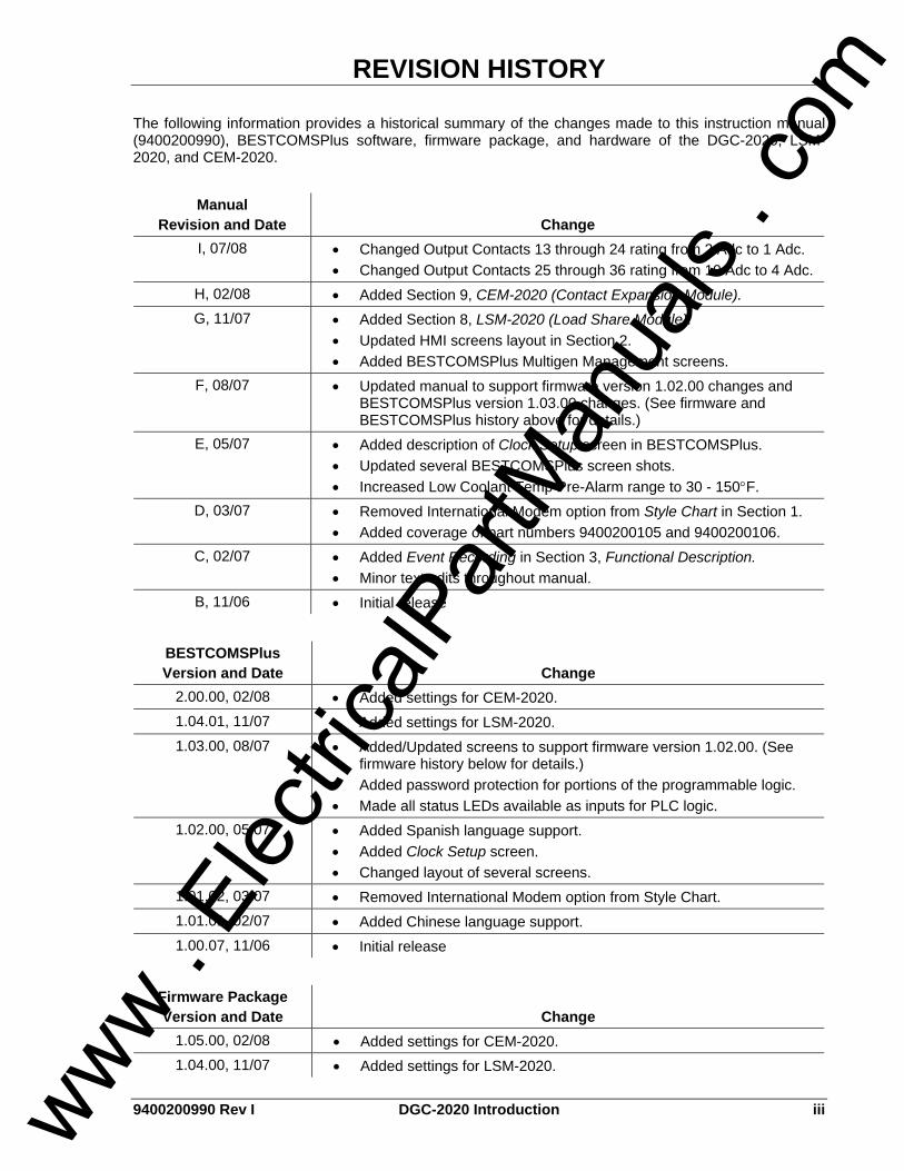
REVISION HISTORY The following information provides a historical summary of the changes made to this instruction manual (9400200990), BESTCOMSPlus software, firmware package, and hardware of the DGC-2020, LSM-2020, and CEM-2020.
Manual Revision and Date Change
I, 07/08 • Changed Output Contacts 13 through 24 rating from 2 Adc to 1 Adc. • Changed Output Contacts 25 through 36 rating from 10 Adc to 4 Adc.
H, 02/08 • Added Section 9, CEM-2020 (Contact Expansion Module). G, 11/07 • Added Section 8, LSM-2020 (Load Share Module).
• Updated HMI screens layout in Section 2. • Added BESTCOMSPlus Multigen Management screens.
F, 08/07 • Updated manual to support firmware version 1.02.00 changes and BESTCOMSPlus version 1.03.00 changes. (See firmware and BESTCOMSPlus history above for details.)
E, 05/07 • Added description of Clock Setup screen in BESTCOMSPlus. • Updated several BESTCOMSPlus screen shots. • Increased Low Coolant Temp Pre-Alarm range to 30 - 150°F.
D, 03/07 • Removed International Modem option from Style Chart in Section 1. • Added coverage of part numbers 9400200105 and 9400200106.
C, 02/07 • Added Event Recording in Section 3, Functional Description. • Minor text edits throughout manual.
B, 11/06 • Initial release
BESTCOMSPlus Version and Date Change
2.00.00, 02/08 • Added settings for CEM-2020. 1.04.01, 11/07 • Added settings for LSM-2020. 1.03.00, 08/07 • Added/Updated screens to support firmware version 1.02.00. (See
firmware history below for details.) • Added password protection for portions of the programmable logic. • Made all status LEDs available as inputs for PLC logic.
1.02.00, 05/07 • Added Spanish language support. • Added Clock Setup screen. • Changed layout of several screens.
1.01.02, 03/07 • Removed International Modem option from Style Chart. 1.01.01, 02/07 • Added Chinese language support. 1.00.07, 11/06 • Initial release
Firmware Package Version and Date Change
1.05.00, 02/08 • Added settings for CEM-2020. 1.04.00, 11/07 • Added settings for LSM-2020.
www . El
ectric
alPar
tMan
uals
. com

iv DGC-2020 Introduction 9400200990 Rev I
Firmware Package Version and Date Change
1.02.00, 08/07 • Added 32 and 40Q protection functions. • Added Automatic Restart function and Exercise Timer. • Added dual settings for 51, 27, and 59 functions. • Added Oil Pressure Crank Disconnect Enable. • Modified Prestart operation during rest cycle. • Added 2 additional Engine kW Overload Pre-Alarms. • Added Low Line Scale Factor for EPS Supplying Load and Engine
kW Overload Pre-Alarms. • Changed the metering range of coolant temperature to 32-410 F. • Changed the Low-Coolant Temp Pre-Alarm range to 32-150 F.
1.01.00, 05/07 • Added Spanish language support. 1.00.08, 03/07 • Minor firmware improvements. 1.00.07, 01/07 • Added Chinese language support. 1.00.06, 11/06 • Initial release
DGC-2020 Hardware
Version and Date Change —, 11/06 • Initial release
LSM-2020 Hardware
Version and Date Change —, 11/07 • Initial release
CEM-2020 Hardware
Version and Date Change —, 02/08 • Initial release
www . El
ectric
alPar
tMan
uals
. com

9400200990 Rev I DGC-2020 Introduction v
CONTENTS
SECTION 1 • GENERAL INFORMATION ................................................................................................ 1-1
SECTION 2 • HUMAN-MACHINE INTERFACE ....................................................................................... 2-1
SECTION 3 • FUNCTIONAL DESCRIPTION ........................................................................................... 3-1
SECTION 4 • BESTCOMSPlus SOFTWARE ........................................................................................... 4-1
SECTION 5 • BESTlogic+ PROGRAMMABLE LOGIC............................................................................. 5-1
SECTION 6 • INSTALLATION .................................................................................................................. 6-1
SECTION 7 • MAINTENANCE AND TROUBLESHOOTING.................................................................... 7-1
SECTION 8 • LSM-2020 (LOAD SHARE MODULE) ................................................................................ 8-1
SECTION 9 • CEM-2020 (CONTACT EXPANSION MODULE) ............................................................... 9-1
APPENDIX A • TIME OVERCURRENT CHARACTERISTIC CURVES................................................... A-1
APPENDIX B • MODBUS™ COMMUNICATION ...................................................................................... B-1
www . El
ectric
alPar
tMan
uals
. com

vi DGC-2020 Introduction 9400200990 Rev I
This page intentionally left blank.
www . El
ectric
alPar
tMan
uals
. com

9400200990 Rev I DGC-2020 General Information i
SECTION 1 • GENERAL INFORMATION TABLE OF CONTENTS
SECTION 1 • GENERAL INFORMATION ................................................................................................ 1-1
DESCRIPTION....................................................................................................................................... 1-1 FEATURES............................................................................................................................................ 1-1 FUNCTIONS .......................................................................................................................................... 1-1
Generator Protection and Metering.................................................................................................... 1-1 Engine Protection and Metering......................................................................................................... 1-1 Event Recording................................................................................................................................. 1-1 Auto-Synchronizer.............................................................................................................................. 1-1 Contact Inputs and Output Contacts .................................................................................................. 1-2 Automatic Transfer Switch Control (Mains Failure)............................................................................ 1-2 Communication................................................................................................................................... 1-2
LSM-2020 (LOAD SHARE MODULE) ................................................................................................... 1-3 CEM-2020 (CONTACT EXPANSION MODULE) .................................................................................. 1-3 STYLE AND PART NUMBERS ............................................................................................................. 1-3
Style Number...................................................................................................................................... 1-3 Part Numbers ..................................................................................................................................... 1-3
SPECIFICATIONS ................................................................................................................................. 1-4 Operating Power ................................................................................................................................ 1-4 Power Consumption ........................................................................................................................... 1-4 Battery Ride Through ......................................................................................................................... 1-4 Current Sensing ................................................................................................................................. 1-4 Voltage Sensing ................................................................................................................................. 1-4 Contact Sensing ................................................................................................................................. 1-4 Engine System Inputs ........................................................................................................................ 1-5 Output Contacts ................................................................................................................................. 1-5 Metering.............................................................................................................................................. 1-6 Generator Protection Functions ......................................................................................................... 1-8 Logic Timers....................................................................................................................................... 1-8 Communication Interface ................................................................................................................... 1-8 Real-Time Clock................................................................................................................................. 1-9 Type Tests........................................................................................................................................ 1-10 Environment ..................................................................................................................................... 1-10 UL/CSA Approvals ........................................................................................................................... 1-10 NFPA Compliance............................................................................................................................ 1-11 CE Compliance ................................................................................................................................ 1-11 Physical ............................................................................................................................................ 1-11
Figures Figure 1-1. DGC-2020 Style Chart ............................................................................................................ 1-3
Tables Table 1-1. Special-Order DGC-2020 Controllers ...................................................................................... 1-4
www . El
ectric
alPar
tMan
uals
. com

ii DGC-2020 General Information 9400200990 Rev I
This page intentionally left blank.
www . El
ectric
alPar
tMan
uals
. com

9400200990 Rev I DGC-2020 General Information 1-1
SECTION 1 • GENERAL INFORMATION DESCRIPTION The DGC-2020 Digital Genset Controller provides integrated engine-genset control, protection, and metering in a single package. Microprocessor based technology allows for exact measurement, setpoint adjustment, and timing functions. Front panel controls and indicators enable quick and simple DGC-2020 operation. Basler Electric communication software (BESTCOMSPlus) allows units to be easily customized for each application. Because of the low sensing burden in the DGC-2020, dedicated potential transformers (PTs) are not required. A wide temperature-range liquid crystal display (LCD) with backlighting can be viewed under a wide range of ambient light and temperature conditions.
FEATURES DGC-2020 Digital Genset Controllers have the following features: • Local and Remote Generator Control • Engine and Generator Protection • Programmable Analog Engine Senders • ECU Communications via SAE J1939 • 16 Programmable Contact Inputs • Programmable Logic • Automatic Transfer Switch Control (Mains Failure) • Integrated RS485 • Auto Synchronizing • Exercise Timer • Additional modules available to expand the capabilities of the DGC-2020
FUNCTIONS DGC-2020 Digital Genset Controllers perform the following functions:
Generator Protection and Metering Multifunction generator protection guards against generator overvoltage, undervoltage, reverse power, loss of excitation, underfrequency, and overfrequency. Overcurrent and phase imbalance protection is available as an option. Each generator protection function has an adjustable pickup and time delay setting. Sixteen inverse time curves enable the DGC-2020 to offer overcurrent protection in a variety of applications. Metered generator parameters include voltage, current, real power (watts), apparent power (VA), and power factor (PF).
Engine Protection and Metering Engine protection features include oil pressure and coolant temperature monitoring, overcrank protection, ECU specific protection elements, and diagnostic reporting. Metered engine parameters include oil pressure, coolant temperature, battery voltage, speed, fuel level, engine load, coolant level (from ECU), ECU specific parameters, and run-time statistics.
Event Recording An event log retains a history of system events in nonvolatile memory. Up to 30 event types are retained and each record contains a time stamp of the first and last occurrence, and the number of occurrences for each event. For more information, see Section 3, Functional Description, Event Recording.
Auto-Synchronizer An optional automatic synchronizer monitors the bus and generator voltages and supplies discrete raise/lower correction signals to synchronize the generator voltage, frequency, and slip angle with that of the bus.
www . El
ectric
alPar
tMan
uals
. com
1-2 DGC-2020 General Information 9400200990 Rev I
Contact Inputs and Output Contacts DGC-2020 controllers have one, dedicated emergency stop contact input and 16 programmable contact inputs. All contact inputs recognize dry contacts. The programmable inputs can be configured to initiate a pre-alarm or alarm. A programmable input can be programmed to receive an input from an automatic transfer switch or override DGC-2020 alarms and protection functions. Each programmable input can be assigned a user-defined name for easy identification at the front panel display and in fault records. Output contacts include three dedicated relays for energizing an engine’s glow plugs, fuel solenoid, and starter solenoid. An additional four user-programmable output contacts are provided if the style number is xxAxxxxxx. If the style number is xxBxxxxxx, an additional twelve output contacts are provided. Additional contact inputs and output contacts can be accommodated with an optional CEM-2020 (Contact Expansion Module). Contact Basler Electric for ordering information.
Automatic Transfer Switch Control (Mains Failure) The DGC-2020 has the ability to detect a mains failure via a single-phase Bus input. A mains failure is established when any one of the following conditions are met: • Bus voltage falls below dead bus threshold • Bus voltage unstable due to overvoltage or undervoltage • Bus voltage unstable due to overfrequency or underfrequency
At this time, the DGC-2020 will start the genset and when ready, apply power to the load via the genset. The DGC-2020 implements open transitions to and from the mains. When the mains returns and is considered stable, the DGC-2020 will transfer the load back to the mains.
Communication Standard DGC-2020 communication features include a standard USB port and SAE J1939 interface. Optional communication features include a dial-out modem and RS-485 communication port. BESTCOMSPlus can communicate with the DGC-2020 through ethernet via an optional LSM-2020 (Load Share Module). Contact Basler Electric for ordering information.
USB Port A USB communication port can be used with BESTCOMSPlus software to quickly configure a DGC-2020 with the desired settings or retrieve metering values and event log records.
CANBus Interface A CANBus interface provides high-speed communication between the DGC-2020 and the engine control unit (ECU) on an electronically controlled engine. This interface provides access to oil pressure, coolant temperature, and engine speed data by reading these parameters directly from the ECU. When available, engine diagnostic data can also be accessed. The CANBus interface supports the following protocols:
• SAE J1939 Protocol - Oil pressure, coolant temperature, and engine speed data are received from the ECU. In addition, DTCs (Diagnostic Trouble Codes) help diagnose any engine or related failures. The engine DTCs are displayed on the front panel of the DGC-2020 and may be obtained using BESTCOMSPlus software.
• MTU/MDEC Protocol - A DGC-2020 connected to a genset equipped with an MTU MDEC receives Oil pressure, coolant temperature, and engine speed data from the engine controller, along with various alarms and pre-alarms that are MDEC specific. In addition, the DGC-2020 tracks and displays the active fault codes issued by the MDEC ECU.
Dial-Out Modem The optional dial-out modem enables remote control, monitoring, and setting of the DGC-2020. When an alarm or pre-alarm condition occurs, the DGC-2020 can dial up to four telephone numbers, in sequence, until an answer is received and the condition is annunciated.
RS-485 Port An optional RS-485 communication port uses the Modbus communication protocol and enables remote control and monitoring of the DGC-2020 over a polled network.
www . El
ectric
alPar
tMan
uals
. com

9400200990 Rev I DGC-2020 General Information 1-3
LSM-2020 (LOAD SHARE MODULE) The optional LSM-2020 in conjunction with the DGC-2020 provides load sharing between governors through an analog load share line. The LSM-2020 communicates through an ethernet port and provides access to the DGC-2020 via ethernet. Refer to Section 8, LSM-2020 (Load Share Module), for more information.
CEM-2020 (CONTACT EXPANSION MODULE) The optional CEM-2020 provides 10 additional contact inputs and 24 additional output contacts to the DGC-2020. The CEM-2020 communicates with the DGC-2020 through a CANBus interface. Refer to Section 9, CEM-2020 (Contact Expansion Module), for more information.
STYLE AND PART NUMBERS
Style Number Standard-order DGC-2020 controllers are identified by a style number which consists of a combination of letters and numbers that define the controller’s electrical characteristics and operational features. The model number, together with the style number, describes the options included in a specific controller. Figure 1-1 illustrates the DGC-2020 style number identification chart.
Figure 1-1. DGC-2020 Style Chart
For example, if a DGC-2020 style number were 51BNBMEAH, the controller would have the following characteristics and operating features. 5 5 Aac current sensing inputs 1 50/60 hertz nominal generator frequency B 3 fixed-function output contacts and 12 programmable output contacts N No RS-485 communication port B Battery backup for real-time clock during losses of control power M Internal dial-out modem—US version E Enhanced generator protection (undervoltage, reverse power, loss of excitation, phase imbalance,
overcurrent, overvoltage, overfrequency, and underfrequency) A Auto-synchronizer H LCD heater
Part Numbers A ten-digit part number specifies the electrical characteristics and operational features of special-order DGC-2020 controllers. Table 1-1 lists the special-order DGC-2020 controllers available along with descriptions of their operating features.
www . El
ectric
alPar
tMan
uals
. com

1-4 DGC-2020 General Information 9400200990 Rev I
Table 1-1. Special-Order DGC-2020 Controllers
Part Number Style Number Special Features 9400200105 51ANBNSNH001 9400200106 11ANBNSNH001
cURus recognized for use in hazardous locations.
SPECIFICATIONS
Operating Power Nominal: 12 or 24 Vdc Range: 6 to 32 Vdc (Withstands cranking ride-through down to 6 Vdc
for 500 ms.) Terminals: 3 (+), 2 (–), 1 (chassis ground)
Power Consumption Sleep Mode: 5W with all relays non-energized Normal Operational Mode: 7.9W - Run mode, LCD heater off, 3 relays energized Maximum Operational Mode: 14.2W - Run mode, LCD heater on, 6 relays energized
Battery Ride Through Withstands cranking ride-through down to 0 V for 50 ms.
Current Sensing Burden: 1 VA Terminals: 68, 69 (A-phase) 71, 72 (B-phase) 74, 75 (C-phase)
1 Aac Current Sensing Continuous Rating: 0.02 to 1.0 Aac 1 Second Rating: 2 Aac
5 Aac Current Sensing Continuous Rating: 0.1 to 5.0 Aac 1 Second Rating: 10 Aac
Voltage Sensing Configuration: Line-to-line or line-to-neutral Range: 12 to 576 V rms, line-to-line Frequency: Style selectable, 50/60 Hz or 400 Hz Frequency Range: 10 to 72 Hz for 50/60 style and 10 to 480 Hz for 400 Hz style Burden: 1 VA 1 Second Rating: 720 V rms Generator Sensing Terminals: 41 (A-phase) 39 (B-phase) 37 (C-phase) 35 (Neutral) Bus Sensing Terminals: 45 (A-phase) 43 (B-phase)
Contact Sensing Contact sensing inputs include 1 emergency stop input and 16 programmable inputs. The emergency stop input accepts normally closed, dry contacts. All programmable inputs accept normally open, dry contacts.
www . El
ectric
alPar
tMan
uals
. com

9400200990 Rev I DGC-2020 General Information 1-5
Terminals Emergency Stop: 46, 47 Programmable Input 1: 30, 2 Input 2: 29, 2 Input 3: 28, 2 Input 4: 27, 2 Input 5: 26, 2 Input 6: 25, 2 Input 7: 24, 2 Input 8: 23, 2 Input 9: 22, 2 Input 10: 21, 2 Input 11: 20, 2 Input 12: 19, 2 Input 13: 18, 2 Input 14: 17, 2 Input 15: 16, 2 Input 16: 15, 2
Engine System Inputs ∗ Stated accuracies are subject to the accuracy of the senders used.
Fuel Level Sensing Resistance Range: 33 to 240 Ω nominal Terminals: 9, 11 (sender common)
Coolant Temperature Sensing Resistance Range: 62.6 to 637.5 Ω nominal Terminals: 10, 11 (sender common)
Oil Pressure Sensing Resistance Range: 34 to 240 Ω nominal Terminals: 8, 11 (sender common)
Engine Speed Sensing Magnetic Pickup Voltage Range: 3 to 35 V peak (6 to 70 V peak-peak) Frequency Range: 32 to 10,000 Hz Terminals: 31 (+), 32 (–) Generator Voltage Range: 12 to 576 V rms Terminals: 41 (A-phase) 39 (B-phase) 37 (C-phase)
Output Contacts
Fuel Solenoid, Engine Crank, and Pre-Start Relays Rating: 30 Adc at 28 Vdc—make, break, and carry ∗ Terminals Fuel Solenoid: RUN – NO, COM Pre-Start: PRE – NO, COM Crank: START – NO, COM
Programmable Relays (12) Rating: 2 Adc at 30 Vdc—make, break, and carry Terminals† Output 1: 52, 51 (common) Output 2: 53, 51 (common) Output 3: 54, 51 (common) Output 4: 56, 55 (common) www .
Elec
tricalP
artM
anua
ls . c
om

1-6 DGC-2020 General Information 9400200990 Rev I
Output 5: 57, 55 (common) Output 6: 58, 55 (common) Output 7: 60, 59 (common) Output 8: 61, 59 (common) Output 9: 62, 59 (common) Output 10: 64, 63 (common) Output 11: 65, 63 (common) Output 12: 66, 63 (common) ∗ Contact rating is reduced to 3 A for part numbers 9400200105 and 9400200106 when used in a
hazardous location. † The number of programmable output contacts provided is determined by the output contacts
character of the DGC-2020 style number. Controllers with output contacts option A have 4 program-mable outputs (Outputs 1, 2, 3, and 4). Controllers with output contacts option B have 12 programmable outputs.
The programmable relays share common terminals: terminal 51 is used for outputs 1, 2, and 3, terminal 55 is used for outputs 4, 5, and 6, terminal 59 is used for outputs 7, 8, and 9, 63 is used for outputs 10, 11, and 12.
Metering
Generator Voltage (rms) Metering Range: 0 to 576 Vac (direct measurement) 577 to 9,999 Vac (through VT using VT ratio setting) VT Ratio Range: 1:1 to 125:1 in primary increments of 1 Accuracy: ∗ ±1.0% of programmed rated voltage or ±2 Vac Display Resolution: 1 Vac ∗ Voltage metering indicates 0 V when generator voltage is below 2% of the full-scale rating.
Generator Current (rms) Generator current is measured at the secondary windings of user-supplied 1 A or 5 A CTs. Metering Range: 0 to 5,000 Aac CT Primary Range: 1 to 5,000 Aac in primary increments of 1 Aac Accuracy: ∗ ±1.0% of programmed rated current or ±2 Aac Display Resolution: 1 Aac ∗ Current metering indicates 0 A when generator current is below 2% of the full-scale rating.
Generator Frequency Generator frequency is sensed through the generator voltage input. Metering Range: 10 to 72 Hz (50/60 Hz) 10 to 480 (400 Hz) Accuracy: ±0.25% or 0.05 Hz Display Resolution: 0.1 Hz
Apparent Power Indicates total kVA and individual line kVA (4-wire, line-to-neutral or 3-wire, line-to-line). Measurement/Calculation Methods Total: kVA = (VL-L × IL ×√3) ÷ 1000 4-Wire, Line-to-Neutral: kVA calculated with respect to neutral 3-Wire, Line-to-Line: A-phase kVA = VAB × IA ÷ 1000 ÷ √3 B-phase kVA = VBC × IB ÷ 1000 ÷ √3 C-phase kVA = VCA × IC ÷ 1000 ÷ √3 Accuracy: ±3% or the full-scale indication or ±2 kVA ∗† ∗ kVA metering indicates 0 kVA when the generator kVA is below 2% of the full-scale rating. † Applies when temperature is between -40°C to +70°C. www .
Elec
tricalP
artM
anua
ls . c
om

9400200990 Rev I DGC-2020 General Information 1-7
Power Factor Metering Range: 0.2 leading to 0.2 lagging Calculation Method: PF = P (3-phase average) ÷ S (3-phase average) Accuracy: ±0.02 ∗ ∗ Applies when temperature is between -40°C to +70°C.
Real Power Indicates total kW and individual line kW (4-wire, line-to-neutral or 3-wire line-to-line) Measurement/Calculation Methods Total: PF × Total kVA 4-Wire, Line-to-Neutral: kW calculated with respect to neutral 3-Wire, Line-to-Line: A-phase kW = VAB × IA × PF ÷ 1000 ÷ √3 B-phase kW = VBC × IB × PF ÷ 1000 ÷ √3 C-phase kW = VCA × IC × PF ÷ 1000 ÷ √3 Accuracy: ±3% of the full-scale indication or ±2 kW ∗† ∗ kW metering indicates 0 kW when the generator kW is below 2% of the full-scale rating. † Applies when temperature is between -40°C to +70°C.
Oil Pressure Metering Range: 0 to 145 psi or 0 to 1,000 kPa Accuracy: ±3% of actual indication or ±2 psi or ±12 kPa (subject to accuracy of
sender) Display Resolution: 1 psi or 1 kPa
Coolant Temperature Metering Range: 32 to 410°F or 0 to 204°C Accuracy: ±3% or actual indication or ±2° (subject to accuracy of sender)
Battery Voltage Metering Range: 6 to 32 Vdc Accuracy: ±3% of actual indication or ±0.2 Vdc Display Resolution: 0.1 Vdc
Engine RPM Metering Range: 0 to 4,500 rpm Accuracy: ∗ ±2% of actual indication or ±2 rpm Display Resolution: 2 rpm ∗ When engine speed is below 2% of full-scale, reported rpm is 0.
Engine Run Time Engine run time is retained in nonvolatile memory. Metering Range: 0 to 99,999 h Update Interval: 6 min Accuracy: ±1% of actual indication or ±12 min Display Resolution: 1/10 hour
Maintenance Timer Maintenance timer indicates the time remaining until genset service is due. Value is retained in nonvolatile memory. Metering Range: 0 to 5,000 h Update Interval: 6 min Accuracy: ±1% or actual indication or ±12 min Display Resolution: 1/10 hour
Fuel Level Metering Range: 0 to 100% Accuracy: ±2% (subject to accuracy of sender) Display Resolution: 1.0%
www . El
ectric
alPar
tMan
uals
. com

1-8 DGC-2020 General Information 9400200990 Rev I
Generator Protection Functions
Overvoltage (59) and Undervoltage (27) Pickup Range: 70 to 576 Vac Pickup Increment: 1 Vac Inhibit Frequency Range: 20 to 400 Hz (27 function only) Activation Delay Range: 0 to 30 s Activation Delay Increment: 0.1 s
Underfrequency (81U) and Overfrequency (81O) Pickup Range: 45 to 66 Hz (50/60 Hz nominal) 360 to 440 Hz (400 Hz nominal) Pickup Increment: 0.1 Hz (50/60 Hz nominal) 0.1 Hz (400 Hz nominal) Activation Delay Range: 0 to 30 s Activation Delay Increment: 0.1 s Inhibit Voltage Range: 70 to 576 Vac (81U function only)
Reverse Power (32) Pickup Range: -50 to 5% Pickup Increment: 0.1% Hysteresis Range: 1 to 10% Hysteresis Increment: 0.1% Activation Delay Range: 0 to 30 s Activation Delay Increment: 0.1 s
Loss of Excitation (40Q) Pickup Range: -150 to 0% Pickup Increment: 0.1% Hysteresis Range: 1 to 10% Hysteresis Increment: 0.1% Activation Delay Range: 0 to 30 s Activation Delay Increment: 0.1 s
Overcurrent (51) (Optional) Pickup Range: 0.18 to 1.18 Aac (1 A current sensing) 0.9 to 7.75 Aac (5 A current sensing) Time Dial Range: 0 to 30 s (fixed time curve) 0 to 9.9 (inverse curve time multiplier) Time Dial Increment: 0.1 Inverse Time Curves: See Appendix A, Time Overcurrent Characteristic Curves
Phase Imbalance (47) (Optional) Pickup Range: 5 to 100 Vac Pickup Increment: 1 Vac Activation Delay Range: 0 to 30 s Activation Delay Increment: 0.1 s
Logic Timers Range: 0 to 10 s Increment: 0.1 s Accuracy: ±15 ms
Communication Interface
USB Specification Compatibility: USB 2.0 Data Transfer Speed: 9600 baud Connector Type: Mini-B jack
www . El
ectric
alPar
tMan
uals
. com

9400200990 Rev I DGC-2020 General Information 1-9
RS-485 (Optional) Baud: 9600 Data Bits: 8 Parity: None Stop Bits: 1 Terminals: 14 (A), 13 (B), and 12 (shield)
CANBus Differential Bus Voltage: 1.5 to 3 Vdc Maximum Voltage: –32 to +32 Vdc with respect to negative battery terminal Communication Rate: 250 kb/s Terminals: 48 (low), 49 (high), and 50 (shield)
Modem (Optional) Connector Type: RJ-11 jack
Real-Time Clock Clock has leap year and selectable daylight saving time correction. Backup capacitor and optional backup battery sustain timekeeping during losses of DGC-2020 operating power. Resolution: 1 s Accuracy: ±1.73 s/d at 25°C
Clock Holdup Battery Holdup Time (Optional): Approximately 10 yrs Battery Type: Rayovac BR2032, lithium, coin-type, 3 Vdc, 190 mAh Basler Electric P/N 38526
NOTES 1.) If the DGC-2020 is providing one end of the J1939 backbone, a 120 Ω terminating resistor should be installed across terminals 48 (CANL) and 49 (CANH). 2.) If the DGC-2020 is not part of the J1939 backbone, the stub connecting the DGC-2020 to the backbone should not exceed 914 mm (3 ft) in length. 3.) The J1939 drain (shield) should be grounded at one point only. If grounded elsewhere, do not connect the drain to the DGC-2020.
CAUTION Replacement of the backup battery for the real-time clock should be performed only by qualified personnel. Do not short-circuit the battery, reverse battery polarity, or attempt to recharge the battery. Observe polarity markings on the battery socket while inserting a new battery. The battery polarity must be correct in order to provide backup for the real-time clock. It is recommended that the battery be removed if the DGC-2020 is to be operated in a salt-fog environment. Salt-fog is known to be conductive and may short-circuit the battery.
NOTE Failure to replace the battery with Basler Electric P/N 38526 may void the warranty.
www . El
ectric
alPar
tMan
uals
. com

1-10 DGC-2020 General Information 9400200990 Rev I
Type Tests Shock and Vibration: EN60068-2-6 Dielectric Strength: IEC 255-5 Impulse: EN60664-1 Transients: EN61000-4-4 Static Discharge: EN61000-4-2
Shock 15 G in 3 perpendicular planes
Vibration Swept over the following ranges for 12 sweeps in each of three mutually perpendicular planes with each 15-minute sweep consisting of the following: 5 to 29 to 5 Hz: 1.5 G peak for 5 min. 29 to 52 to 29 Hz: 0.036” DA for 2.5 min. 52 to 500 to 52 Hz: 5 G peak for 7.5 min.
Radio Interference Type tested using a 5 W, hand-held transceiver operating at random frequencies centered around 144 and 440 MHz with the antenna located within 150 mm (6”) of the device in both vertical and horizontal planes.
HALT (Highly Accelerated Life Testing) HALT is used by many manufacturers to prove that their products will provide the user with many years of reliable service. HALT subjects the device to extremes in temperature, shock, and vibration to simulate years of operation, but in a much shorter period span. HALT allows Basler Electric to evaluate all possible design elements that will add to the life of this device. As an example of some of the extreme testing conditions, the DGC-2020 was subjected to temperature tests (tested over a temperature range of -100°C to +115°C), vibration tests (of 5 to 50 G at +20°C), and temperature/vibration tests (tested at 40 G over a temperature range of -80°C to +90°C). Combined temperature and vibration testing at these extremes proves that the DGC-2020 is expected to provide long-term operation in a rugged environment. Note that the vibration and temperature extremes listed in this paragraph are specific to HALT and do not reflect recommended operation levels. These operational ratings are included in Section 1 of this manual.
Ignition System Tested in closed proximity to an unshielded, unsuppressed Altronic DISN 800 Ignition System.
Environment Temperature Operating: –40 to 70°C (–40 to 158°F) Storage: –40 to 85°C (–40 to 185°F) Humidity: IEC 68-2-38 Salt Fog: ASTM B 17-73, IEC 68-2-11 Ingress Protection: IEC IP54 for front panel
UL/CSA Approvals “cURus” recognized to UL 508 and CSA C22.2 No.14
Part Numbers 9400200105 and 9400200106 “cURus” recognized per Standard 1604, Electrical Equipment for Use in Class I and II, Division 2, and Class III Hazardous (Classified) Locations, Class I, Division 2, Zone 2, Groups A, B, C, D, Temperature Code - T4.
CAUTION To follow UL/CSA guidelines, replacement of the backup battery for the real-time clock should be performed only by qualified personnel.
www . El
ectric
alPar
tMan
uals
. com

9400200990 Rev I DGC-2020 General Information 1-11
This equipment is suitable for use in Class I, Division 2, Groups A, B, C, D, or non-hazardous locations only.
NFPA Compliance Complies with NFPA Standard 110, Standard for Emergency and Standby Power.
CE Compliance This product complies with the requirements of the following EC Directives: • Low Voltage Directive (LVD) - 73/23/EEC as amended by 93/68/EEC • Electromagnetic Compatibility (EMC) - 89/336/EEC as amended by 92/31/EEC and 93/68/EEC
This product conforms to the following Harmonized Standards: • EN 50178:1997 - Electronic Equipment for use in Power Installations • EN 61000-6-4:2001 - Electromagnetic Compatibility (EMC), Generic Standards, Emission Standard
for Industrial Environments • EN 61000-6-2:2001 - Electromagnetic Compatibility (EMC), Generic Standards, Immunity for
Industrial Environments
Physical Weight: 2 kg (4.4 lb) Dimensions: See Section 6, Installation.
WARNING! - EXPLOSION HAZARD (9400200105 and 9400200106 only)
Substitution of components may impair suitability for Class I, Division 2. Do not disconnect equipment unless power has been switched off or the area is known to be non-hazardous.
www . El
ectric
alPar
tMan
uals
. com

1-12 DGC-2020 General Information 9400200990 Rev I
This page intentionally left blank.
www . El
ectric
alPar
tMan
uals
. com

9400200990 Rev I DGC-2020 Human-Machine Interface i
SECTION 2 • HUMAN-MACHINE INTERFACE TABLE OF CONTENTS
SECTION 2 • HUMAN-MACHINE INTERFACE ....................................................................................... 2-1
INTRODUCTION.................................................................................................................................... 2-1 FRONT PANEL...................................................................................................................................... 2-1 DISPLAY OPERATION.......................................................................................................................... 2-2
Login and Permissions ....................................................................................................................... 2-2 Summary Screen and Configurable Metering .................................................................................... 2-3 Sleep Mode ........................................................................................................................................ 2-3 Changing a Setting............................................................................................................................. 2-3 Front Panel Display Structure ............................................................................................................ 2-4
REAR PANEL ...................................................................................................................................... 2-12
Figures Figure 2-1. Front Panel HMI ...................................................................................................................... 2-1 Figure 2-2. Metering Screen Branches ..................................................................................................... 2-4 Figure 2-3. Settings Screen Branches ...................................................................................................... 2-5 Figure 2-4. DGC-2020 Rear Panel HMI .................................................................................................. 2-12
Tables Table 2-1. Front Panel HMI Descriptions .................................................................................................. 2-2 Table 2-2. General Settings Screen Branches.......................................................................................... 2-5 Table 2-3. Communications Screen Branches.......................................................................................... 2-6 Table 2-4. System Params Screen Branches ........................................................................................... 2-6 Table 2-5. Alarm Configuration Screen Branches..................................................................................... 2-7 Table 2-6. Generator Protection Screen Branches ................................................................................... 2-9 Table 2-7. Breaker Management Screen Branches................................................................................ 2-10 Table 2-8. Bias Control Screen Branches ............................................................................................... 2-11 Table 2-9. Multigen Management Screen Branches............................................................................... 2-11 Table 2-10. Rear Panel HMI Descriptions............................................................................................... 2-13
www . El
ectric
alPar
tMan
uals
. com
ii DGC-2020 Human-Machine Interface 9400200990 Rev I
This page intentionally left blank.
www . El
ectric
alPar
tMan
uals
. com

9400200990 Rev I DGC-2020 Human-Machine Interface 2-1
SECTION 2 • HUMAN-MACHINE INTERFACE INTRODUCTION This section describes the components of the DGC-2020 human-machine interface (HMI). DGC-2020 HMI components are located on the front panel (controls and indicators) and the rear panel (terminals and connectors).
FRONT PANEL Figure 2-1 illustrates the front panel HMI of the DGC-2020. Table 2-1 lists the call-outs of Figure 2-1 along with a description of each HMI component.
Figure 2-1. Front Panel HMI
www . El
ectric
alPar
tMan
uals
. com

2-2 DGC-2020 Human-Machine Interface 9400200990 Rev I
Table 2-1. Front Panel HMI Descriptions
Locator Description A Liquid Crystal Display. The backlit, 64 by 128 pixel LCD serves as the local information
source for metering, alarms, pre-alarms, and protective functions. Display operation is maintained at -40°C.
B Not in Auto Indicator. This red LED lights when the DGC-2020 is not operating in Auto mode.
C Alarm Indicator. This red LED lights continuously during alarm conditions and flashes during pre-alarm conditions.
D Supplying Load Indicator. This green LED lights when the generator current is greater than EPS threshold current.
E Alarm Silence Pushbutton. Pressing this button opens the relay output programmed as the horn output.
F Lamp Test Pushbutton. Pressing this button tests the DGC-2020 indicators by exercising all LCD pixels and lighting all LEDs.
G Auto Pushbutton and Mode Indicator. Pressing the Auto button places the DGC-2020 in Auto mode. The green Auto mode LED lights when Auto mode is active.
H Off Pushbutton and Mode Indicator. Pressing this button places the DGC-2020 in Off mode. The red Off mode LED lights when the DGC-2020 is in Off mode.
I Run Pushbutton and Mode Indicator. Pressing this button places the DGC-2020 in Run mode. The green Run mode LED lights when Run mode is active.
J Reset Pushbutton. This button is pressed to cancel a settings editing session and discard any settings changes. When pressed, this button also resets the Breaker Management Pre-Alarms.
K Arrow Pushbuttons. These four buttons are used to navigate through the front panel display menus and modify settings. The left- and right-arrow buttons are used to navigate through the menu levels. The right-arrow button is pressed to move downward through the menu levels and the left-arrow button is pressed to move upward. Within a level, the up-arrow and down-arrow buttons are used to move among items within the menu level. Pressing the down-arrow button moves to items lower in the list. Pressing the up-arrow button moves to items higher in the list. During a settings editing session, the up- and down-arrow buttons are used to raise and lower the value of the selected setting.
L Edit Pushbutton. Pressing this button starts an editing session and enables changes to DGC-2020 settings. At the conclusion of an editing session, the Edit pushbutton is pressed again to save the setting changes.
DISPLAY OPERATION The front panel display is used to make settings changes and display metering values. Refer to call-outs J, K, and L in Table 2-1 for information on changing settings through the front panel and navigating through the Metering screens.
Login and Permissions
Login To login, navigate to the SETTINGS, ENTER PASSWORD screen and press the Edit key. Use the Up/Down arrow keys to scroll through the characters. Use the Left/Right arrow keys to enter more characters. Once the password has been entered, press the Edit key to login. A LOGOUT selection now appears in the list of SETTINGS. To logout, navigate to SETTINGS, LOGOUT and press the Edit key. The LOGOUT selection is removed from the SETTINGS list.
www . El
ectric
alPar
tMan
uals
. com

9400200990 Rev I DGC-2020 Human-Machine Interface 2-3
Permissions If communications access is active through the modem or USB, the front panel will display REMOTE COMMS, FRONT PANEL IS READ ONLY and the summary screen. This informs the user that the front panel can only be used for viewing metering data and settings information. Remote access must be ended before modifying settings through the front panel.
Summary Screen and Configurable Metering The summary screen can be set to standard or scrolling. When set to standard, only the following are displayed: • VOLT∗ • AMP∗ • PH∗ • Hz • OIL • FUEL • TEMP • BATT ∗ Information for each phase is obtained by pressing the Up or Down arrow keys on the front panel HMI. When the summary screen is set to scrolling, you can select/configure the metering values that are displayed. Up to 20 values can be displayed and these values will scroll at a delay time specified by the user. To select a standard or scrolling summary, navigate to the SETTINGS, GENERAL SETTINGS, FRONT PANEL HMI screen and edit the SUMMARY VIEW. The SCROLL DELAY setting is also found on this screen. To select the scrolling values, navigate to the SETTINGS, GENERAL SETTINGS, FRONT PANEL HMI screen and edit the CONFIGURABLE METERING. The following values may be selected by the user to be placed in the scrolling summary: • NONE (Removes a line from the scrolling list) • BLANK (Shows nothing on this line) • OIL P • TEMP • BATT V • RPM • RPM SRC • FUEL • RUN HRS • GEN VAB • GEN VBC • GEN VCA • GEN VAN • GEN VBN • GEN VCN • BUS Hz
• BUS V • GEN Hz • GEN PF • KWH • GEN IA • GEN IB • GEN IC • KW A • KW B • KW C • KW TOT • KVA A • KVA B • KVA C • KVA TOT
Sleep Mode Sleep mode serves as a power saving feature. If the DGC-2020 is in Off mode or Auto mode not running and a key is not pressed for more than 15 minutes, the front panel LCD backlight and LCD heater are turned off. The DGC-2020 resumes normal display operation when any front panel button is pressed or the genset is started remotely via the ATS input. The DGC-2020 will not go to sleep while in an Alarm state. If needed, Sleep mode can be permanently disabled via BESTCOMSPlus or the front panel.
Changing a Setting To change a setting, navigate to the setting you want to change and press the Edit key. If you are not already logged in, you will be asked to enter your password at this time. Use the Up/Down arrows to raise or lower the value. Press the Edit key again when finished.
www . El
ectric
alPar
tMan
uals
. com

2-4 DGC-2020 Human-Machine Interface 9400200990 Rev I
Front Panel Display Structure The front panel display begins with the SUMMARY SCREEN. Pressing the Right arrow key will open the MAIN MENU screen. The MAIN MENU screen consists of METERING and SETTINGS. The METERING screen branches are shown in Figure 2-2. The SETTINGS screen branches are shown in Figure 2-3. Details of the SETTINGS screen branches are listed in Tables 2-2 through 2-9.
Figure 2-2. Metering Screen Branches
www . El
ectric
alPar
tMan
uals
. com

9400200990 Rev I DGC-2020 Human-Machine Interface 2-5
P0052-37
SETTINGS
GENERAL SETTINGSCOMMUNICATIONSSYSTEM PARAMSALARM CONFIGURATIONGENERATOR PROTECTIONBREAKER MANAGEMENTBIAS CONTROLMULTIGEN MANAGEMENTENTER PASSWORD
GENERAL SETTINGS
Refer to Table 2-2
COMMUNICATIONS
Refer to Table 2-3
SYSTEM PARAMS
Refer to Table 2-4
ALARM CONFIGURATION
Refer to Table 2-5
GENERATOR PROTECTION
Refer to Table 2-6
BREAKER MANAGEMENT
Refer to Table 2-7
BIAS CONTROL
Refer to Table 2-8
MULTIGEN MANAGEMENT
Refer to Table 2-9
(Available when Load Sharing Module is enabled.)
Figure 2-3. Settings Screen Branches
Table 2-2. General Settings Screen Branches
• FRONT PANEL HMI o SUMMARY VIEW o SCROLL DELAY o LCD CONTRAST o SLEEP MODE o LANGUAGE o CONFIGURABLE METERING
• CONFIGURE DATE/TIME o YEAR o MONTH o DAY o HOURS o MINUTES o SECONDS o UTC OFFSET o DST ENABLED
• VIEW DATE/TIME • VERSION INFO
o FIRMWARE VERSION o BOOT CODE o SERIAL NUMBER o PART NUMBER o MODEL NUMBER o LANGUAGE VERSION o LANGUAGE PART NUM www . El
ectric
alPar
tMan
uals
. com

2-6 DGC-2020 Human-Machine Interface 9400200990 Rev I
Table 2-3. Communications Screen Branches • CANBUS SETUP
o CANBUS ENABLE o DTC ENABLE o ECU CONF o CANBUS ADDR o ECU OPT SLCT o ECU PULSING o ENG SHTDN TM o PLS CYCL TM o ECU SET TM o RESP TIMEOUT
• RS485 SETUP o COMM BAUD o COMM PARITY o MODBUS ADDR
Table 2-4. System Params Screen Branches
• SYSTEM SETTINGS o LSM SETUP
ENABLE CANBUS ADDRESS (Visible when LSM-2020 is enabled.) VERSION INFO (Visible when LSM-2020 is enabled.) TCP/IP SETTINGS (Visible when LSM-2020 is enabled.)
• IP ADDRESS • SUBNET MASK • GATEWAY ADDRESS • DHCP ENABLE
o CEM SETUP ENABLE CANBUS ADDR (Visible when CEM-2020 is enabled.) VERSION INFO (Visible when CEM-2020 is enabled.)
o GEN CONNECT o RATED KW o RATED VOLTS o RATED FREQ o RATED RPM o COOLDWN TIME o EPS
EPS THRESHLD LOW LINE OVERRIDE
• SCALE FACTOR o FUEL LVL TYP o SYSTEM UNITS o BATTERY VOLT o FLYWHL TEETH o SPEED SOURCE o MAINT RESET o NFPA LEVEL o HORN o 1 PHASE O-RIDE o RATED PF o POWER UP DELAY
• CRANK SETTINGS o DISCNCT LMIT o PRECRNK DELY o PRESTRT CNTCT o STYLE o # CYCLES
www . El
ectric
alPar
tMan
uals
. com

9400200990 Rev I DGC-2020 Human-Machine Interface 2-7
o CYCLE TIME o PRESTART REST CONFIG o OIL PRS CRANK DISC
• AUTOMATIC RESTART o ENABLE o ATTEMPTS o INTERVAL
• EXERCISE TIMER o MODE o RUN WITH LOAD o START HOUR o START MINUTE o RUN HOURS o RUN MINUTES
• SENSING TRANS o GEN PT PRI V o GEN PT SEC V o GEN CT PRI A o BUS PT PRI V o BUS PT SEC V
• ENGINE STATISTICS o START YEAR o START MONTH o START DAY o # STARTS o HRS TO MAINT o KW-HRS o TOTAL HRS o LOADED HRS o UNLOADED HRS
Table 2-5. Alarm Configuration Screen Branches
• PRE-ALARMS o HIGH COOLANT TEMP
ENABLE THRESHOLD
o LOW COOLANT TEMP ENABLE THRESHOLD
o LOW OIL PRESSURE ENABLE THRESHOLD
o LOW FUEL LEVEL ENABLE THRESHOLD
o ENGINE OVERLOAD ENABLE THRESHOLD
o MAINTENANCE INTERVAL ENABLE THRESHOLD
o BATTERY OVERVOLTAGE ENABLE THRESHOLD
o LOW BATTERY VOLTAGE ENABLE THRESHOLD ACTIVATN DLY
o WEAK BATTERY VOLTAGE ENABLE www . El
ectric
alPar
tMan
uals
. com

2-8 DGC-2020 Human-Machine Interface 9400200990 Rev I
THRESHOLD ACTIVATN DLY
o HIGH FUEL LEVEL ENABLE THRESHOLD ACTIVATN DLY
o ACTIVE DTC (Visible when DTC Support is enabled.) ENABLE
o ECU COMMS FAIL (Visible when ECU Support is enabled.) ENABLE
o COOLANT LEVEL ENABLE THRESHOLD
o AVR OUTPUT LIMIT (Visible when LSM-2020 is enabled.) ENABLE ACTIVATN DLY
o GOV OUTPUT LIMIT (Visible when LSM-2020 is enabled.) ENABLE ACTIVATN DLY
o INTERGENSET COMM FAIL (Visible when LSM-2020 is enabled.) ENABLE
o LSM COMM FAIL (Visible when LSM-2020 is enabled.) ENABLE
o ID MISSING (Visible when LSM-2020 is enabled.) ENABLE
o ID REPEAT (Visible when LSM-2020 is enabled.) ENABLE
o CEM COMM FAIL (Visible when CEM-2020 is enabled.) ENABLE
• ALARMS o HIGH COOLANT TEMP
ENABLE THRESHOLD ARMING DELAY
o LOW OIL PRESSURE ENABLE THRESHOLD ARMING DELAY
o LOW FUEL LEVEL ENABLE THRESHOLD ACTIVATN DLY
o OVERSPEED ENABLE THRESHOLD ACTIVATN DLY
o COOLANT LEVEL ENABLE THRESHOLD
• SENDER FAIL o COOL TEMP SENDR FAIL
CONFIG TYPE ACTIVATN DLY
NOTE The HIGH COOLANT TEMP and LOW OIL PRESSURE alarms have an ARMING DLY setting that disables the alarm for the specified time after engine startup.
www . El
ectric
alPar
tMan
uals
. com

9400200990 Rev I DGC-2020 Human-Machine Interface 2-9
o OIL PRESS SENDR FAIL CONFIG TYPE ACTIVATN DLY
o FUEL LEVL SENDR FAIL CONFIG TYPE ACTIVATN DLY
o VOLTAGE SENSE FAIL CONFIG TYPE ACTIVATN DLY
o SPEED SENDR FAIL TIME DELAY
Table 2-6. Generator Protection Screen Branches
• 27 UNDERVOLTAGE o 27-1 / 27-2
LOW LINE OVERRIDE • SCALE FACTOR
3 / 1 PHASE SETTINGS • PICKUP • HYSTERESIS • TIME DELAY • FREQ INHIBIT • ALARM CONFIG
• 59 OVERVOLTAGE o 59-1 / 59-2
LOW LINE OVERRIDE • SCALE FACTOR
3 / 1 PHASE SETTINGS • PICKUP • HYSTERESIS • TIME DELAY • ALARM CONFIG
• 47 PHASE IMBALANCE (Optional) o PICKUP o HYSTERESIS TIME DELAY o ALARM CONFIG
• 81 O/U FREQUENCY o UNDERFREQUENCY
INHIBIT VOLTS PICKUP HYSTERESIS TIME DELAY ALARM CONFIG
o OVERFREQUENCY PICKUP HYSTERESIS TIME DELAY ALARM CONFIG
• 51 OVERCURRENT (Optional) o 51-1 / 51-2
LOW LINE OVERRIDE • SCALE FACTOR
3 / 1 PHASE SETTINGS • PICKUP • TIME DIAL • CURVE • ALARM CONFIG
• 32 REVERSE POWER o 3 / 1 PHASE SETTINGS
PICKUP www . El
ectric
alPar
tMan
uals
. com

2-10 DGC-2020 Human-Machine Interface 9400200990 Rev I
HYSTERESIS TIME DELAY ALARM CONFIG
• 40 LOSS OF EXCITATION o 3 / 1 PHASE SETTINGS
PICKUP HYSTERESIS TIME DELAY ALARM CONFIG
Table 2-7. Breaker Management Screen Branches
• BREAKER HARDWARE o MAINS FAIL TRANSFER
ENABLE RETURN DELAY TRANSFER DELAY MAX TRANSFER TIME
o CLOSE WAIT TIME TIME
o GEN BREAKER CONTINUOUS CLOSING TIME DEAD BUS CL ENBL
o MAINS BREAKER CONFIGURED CONTINUOUS CLOSING TIME
• BUS CONDITION DETECT o GEN DEAD
THRESHOLD TIME DELAY
o GEN STABLE OV PICKUP OV DROPOUT UV PICKUP UV DROPOUT OF PICKUP OF DROPOUT UF PICKUP UF DROPOUT TIME DELAY
o GEN FAILED TIME DELAY
o BUS DEAD THRESHOLD TIME DELAY
o BUS STABLE OV PICKUP OV DROPOUT UV PICKUP UV DROPOUT OF PICKUP OF DROPOUT UF PICKUP UF DROPOUT TIME DELAY
o BUS FAILED TIME DELAY
• SYNCHRONIZER o TYPE www .
Elec
tricalP
artM
anua
ls . c
om
9400200990 Rev I DGC-2020 Human-Machine Interface 2-11
o SLIP FREQ o REGUL OFFSET o CLOSING ANGLE o VS>VD o TIME DELAY o FAIL DELAY
Table 2-8. Bias Control Screen Branches
• AVR BIAS CONTROL o OUTPUT (Visible when LSM-2020 is enabled.)
TYPE o CONTACT (Visible when OUTPUT TYPE = CONTACT.)
TYPE o VOLT CTRL GAINS (Visible when OUTPUT TYPE = ANALOG.)
KP KI KD TD LOOP GAIN
• GOV BIAS CONTROL o OUTPUT (Visible when LSM-2020 is enabled.)
TYPE o CONTACT (Visible when OUTPUT TYPE = CONTACT.)
TYPE o SPEED TRIM
ENABLE o SPEED CTRL GAINS (Visible when OUTPUT TYPE = ANALOG.)
KP KI KD TD LOOP GAIN
o KW CTRL LOAD CTRL ENABLE KP KI KD TD LOOP GAIN DROOP DROOP GAIN RAMP RATE BASELOAD LVL BRKR OPEN PT
Table 2-9. Multigen Management Screen Branches
• AVR ANALOG OUTPUT o OUTPUT TYPE o MIN OUTPUT o MAX OUTPUT o VOLT RESPONSE
• GOV ANALOG OUTPUT o OUTPUT TYPE o MIN OUTPUT o MAX OUTPUT o SPD RESPONSE
• LOAD SHARE LINE o MIN VOLTAGE o MAX VOLTAGE www . El
ectric
alPar
tMan
uals
. com

2-12 DGC-2020 Human-Machine Interface 9400200990 Rev I
• DEMAND START STOP o ENABLE o START TD 1 o START TD 2 o STOP TD o START LVL 1 o START LVL 2 o STOP LVL
• SEQUENCING o SEQUENCE ID o MODE o MAX GEN START o MAX GEN STOP
• NETWORK CONFIG
REAR PANEL All DGC-2020 terminals and connectors are located on the rear panel. Rear panel terminals and connectors are illustrated in Figure 2-4. (To show the terminals and connectors, Figure 2-4 shows the DGC-2020 with the rear cover removed.) Table 2-10 lists the call-outs of Figure 2-4 along with a description of each connector type.
Figure 2-4. DGC-2020 Rear Panel HMI www .
Elec
tricalP
artM
anua
ls . c
om

9400200990 Rev I DGC-2020 Human-Machine Interface 2-13
Table 2-10. Rear Panel HMI Descriptions
Locator Description A, D The majority of external, DGC-2020 wiring is terminated at 15-position connectors with
compression terminals. These connectors plug into headers on the DGC-2020. The connectors and headers have a dovetailed edge that ensures proper connector orientation. Each connector and header is uniquely keyed to ensure that a connector mates only with the correct header. Connector screw terminals accept a maximum wire size of 12 AWG.
B The mini-B USB socket mates with a standard USB cable and is used with a PC running BESTCOMSPlus software for local communication with the DGC-2020.
C DGC-2020 controllers with an optional, internal, dial-out modem connect to a telephone line through a USOC RJ-11 jack.
E Connections to the DGC-2020 Start (starter), Run (fuel solenoid), and Pre (glow plug) output contacts are made directly to each relay through quarter-inch, male, quick-connect terminals.
F An optional battery backup for the real-time clock is available when ordering. See Section 7, Maintenance and Troubleshooting, for instructions on replacing the battery. Failure to replace the battery with Basler Electric P/N 38526 may void the warranty.
www . El
ectric
alPar
tMan
uals
. com

2-14 DGC-2020 Human-Machine Interface 9400200990 Rev I
This page intentionally left blank.
www . El
ectric
alPar
tMan
uals
. com

9400200990 Rev I DGC-2020 Functional Description i
SECTION 3 • FUNCTIONAL DESCRIPTION TABLE OF CONTENTS
SECTION 3 • FUNCTIONAL DESCRIPTION ........................................................................................... 3-1
INTRODUCTION.................................................................................................................................... 3-1 DGC-2020 FUNCTION BLOCKS........................................................................................................... 3-1
Power Supply ..................................................................................................................................... 3-1 Microprocessor................................................................................................................................... 3-1 Generator Voltage Sensing Inputs ..................................................................................................... 3-2 Bus Voltage Sensing Inputs ............................................................................................................... 3-2 Current Sensing Inputs....................................................................................................................... 3-2 Analog Engine Sender Inputs............................................................................................................. 3-2 Speed Signal Inputs ........................................................................................................................... 3-3 Contact Inputs .................................................................................................................................... 3-3 Front Panel HMI ................................................................................................................................. 3-4 Remote Display Panel (Optional) ....................................................................................................... 3-4 Communication Ports ......................................................................................................................... 3-4 Output Contacts ................................................................................................................................. 3-8
BREAKER MANAGEMENT................................................................................................................... 3-8 Introduction......................................................................................................................................... 3-8 Determining Breaker Status ............................................................................................................... 3-9 Processing Breaker Requests............................................................................................................ 3-9 Breaker Operation .............................................................................................................................. 3-9
EVENT RECORDING.......................................................................................................................... 3-10
Figures Figure 3-1. Function Block Diagram.......................................................................................................... 3-1
Tables Table 3-1. ECU Parameters Obtained from CAN Interface ...................................................................... 3-5 Table 3-2. Engine Configuration Parameters Obtained from CAN Interface ............................................ 3-6 Table 3-3. Diagnostic Information Obtained Over the CAN Interface ....................................................... 3-7 Table 3-4. Event List................................................................................................................................ 3-10
www . El
ectric
alPar
tMan
uals
. com
ii DGC-2020 Functional Description 9400200990 Rev I
This page intentionally left blank.
www . El
ectric
alPar
tMan
uals
. com

9400200990 Rev I DGC-2020 Functional Description 3-1
SECTION 3 • FUNCTIONAL DESCRIPTION INTRODUCTION This section describes how the DGC-2020 functions. A detailed description of each function block is provided in the paragraphs under the heading of DGC-2020 Function Blocks. DGC-2020 operating and metering features are described in Section 4, BESTCOMSPlus Software.
DGC-2020 FUNCTION BLOCKS To ease understanding, DGC-2020 functions are illustrated in the block diagram of Figure 3-1. The following paragraphs describe each function in detail.
Microprocessor
Power Supply
Battery Voltage Sensing
Sender Input Sensing
(To Internal Circuitry)
Generator Current Sensing
Bus Voltage Sensing
Generator Voltage Sensing
MPU Speed Sensing
Programmable Dry Contact Inputs (16)
USB Com Port
J1939 CAN Com Port
RS-485 Com Port (Optional)
Modem Com Port (Optional)
Emergency Stop Contact Input
Front Panel HMI and LCD
Remote Display Panel Driver (RDP-110)
Programmable Output Contacts
(4 or 12)
Fuel Solenoid Output Contacts
Engine Crank Output Contacts
Pre-start Output Contacts
P0040-0406-20-06
Sensing
Com Ports
Sensing
HMI
Output Contacts
Figure 3-1. Function Block Diagram
Power Supply The internal, switch-mode power supply uses the applied battery voltage to generate operating power for the internal circuitry of the DGC-2020. The power supply accepts a nominal battery voltage of 12 or 24 Vdc and has an operating range of 6 to 32 Vdc. Battery voltage is applied to terminals 2 (–) and 3 (+). Operating power must be of the correct polarity. Although reverse polarity will not cause damage, the DGC-2020 will not operate.
Battery Voltage Sensing Voltage applied to the power supply is filtered and reduced to a suitable level for sensing by the microprocessor.
Microprocessor The microprocessor controls the overall functionality of the DGC-2020 and makes decisions based on programming and system inputs. Circuits relating to the microprocessor inputs are described in the following paragraphs.
www . El
ectric
alPar
tMan
uals
. com

3-2 DGC-2020 Functional Description 9400200990 Rev I
Zero Crossing Detection The zero crossing of A-phase to B-phase or A-phase to C-phase (user-selectable) line voltage is detected and used to calculate the generator frequency. The zero crossing of A-phase to B-phase bus voltage is used to calculate the bus frequency.
Analog-to-Digital Converter Scaled and conditioned signals representing the sensing voltage, sensing current, coolant temperature, fuel level, oil pressure, and battery voltage are digitized by the microprocessor’s analog-to-digital converter. The digitized information is stored in random access memory (RAM) and used by the microprocessor for all metering and protection functions.
Watchdog Timer The watchdog timer monitors the firmware executed by the microprocessor. If the firmware ceases normal operation, the watchdog timer will reset the microprocessor. After reset, the microprocessor will resume normal operation if the condition that caused the watchdog reset is no longer present. If the condition is still present, the unit will reset repeatedly until it can resume normal operation.
Generator Voltage Sensing Inputs Voltages applied to the generator voltage sensing inputs are scaled to levels suitable for use by the internal circuitry. Generator voltage sensing configuration is menu-selectable. The generator voltage sensing inputs accept a maximum voltage of 576 Vrms, line-to-line. Sensing voltage is applied to terminals 41 (A-phase), 39 (B-phase), 37 (C-phase), and 35 (neutral).
Bus Voltage Sensing Inputs Voltage applied to the bus voltage sensing input is scaled to a level suitable for use by the internal circuitry. The bus voltage sensing input accepts a maximum voltage of 576 Vrms. Sensing voltage is applied to terminals 45 (A-phase) and 43 (B-phase).
Current Sensing Inputs Generator currents are sensed and scaled to values suitable for use by the internal circuitry. DGC-2020 controllers with 1 ampere current sensing (style number 1xxxxxxxx) accept a maximum current value of 1 Aac. DGC-2020 controllers with 5 ampere current sensing (style number 5xxxxxxxx) accept a maximum current value of 5 Aac. Sensing current is applied to terminals 68 (IA–) and 69 (IA+), 71 (IB–) and 72 (IB+), and 74 (IC–) and 75 (IC+).
Analog Engine Sender Inputs Programmable analog engine sender inputs give the DGC-2020 user the flexibility to select the engine sender to be used in an application. Information about programming the sender inputs is provided in Section 4, BESTCOMSPlus Software.
Oil Pressure A current is provided to the oil pressure sender. The developed voltage is measured and scaled for use by the internal circuitry. An open circuit or short circuit across the oil pressure sender terminals will cause the DGC-2020 to indicate a failed sender. Oil pressure senders that are compatible with the DGC-2020 include Datcon model 02505-00, Isspro model R8919, and Stewart-Warner models 411K and 411M. Other senders may also be used. BESTCOMSPlus software allows for the programming of sender characteristics. See Section 4, BESTCOMSPlus Software, for more information. Oil pressure sender connections are made at terminals 8 and 11 (sender common).
Coolant Temperature A current is provided to the coolant temperature sender. The developed voltage is measured and scaled for use by the internal circuitry. An open circuit or short circuit across the coolant temperature sender terminals will cause the DGC-2020 to indicate a failed sender. Coolant temperature senders that are compatible with the DGC-2020 include Datcon model 02019-00, Faria model TS4042, Isspro model R8959, and Stewart-Warner model 334P. Other senders may be used. BESTCOMSPlus software allows for the programming of sender characteristics. See Section 4, BESTCOMSPlus Software, for more information.
www . El
ectric
alPar
tMan
uals
. com

9400200990 Rev I DGC-2020 Functional Description 3-3
Coolant temperature sender connections are made at terminals 10 and 11 (sender common).
Fuel Level A current is provided to the fuel level sender. The developed voltage is measured and scaled for use by the internal circuitry. An open circuit or short circuit across the fuel level sender terminals will cause the DGC-2020 to indicate a failed sender. Fuel level senders that are compatible with the DGC-2020 include Isspro model R8925. Other senders may be used. BESTCOMSPlus software allows for the programming of sender characteristics. See Section 4, BESTCOMSPlus Software, for more information. Fuel level sender connections are made at terminals 9 and 11 (sender common).
Speed Signal Inputs The DGC-2020 uses signals from the generator voltage sensing inputs and magnetic pickup input to detect machine speed.
Generator Voltage Sensing Input The generator voltage sensed by the DGC-2020 is used to measure frequency and can be used to measure machine speed. Sensing voltage is applied to terminals 41 (A-phase), 39 (B-phase), 37 (C-phase), and 35 (Neutral).
Magnetic Pickup Input (MPU) Voltage supplied by a magnetic pickup is scaled and conditioned for use by the internal circuitry as a speed signal source. The MPU input accepts a signal over the range of 3 to 35 volts peak and 32 to 10,000 hertz. Magnetic pickup connections are provided at terminals 31 (+) and 32 (–).
Contact Inputs The DGC-2020 has seventeen contact sensing inputs: an emergency stop input and 16 programmable inputs. Additional contact inputs can be accommodated with a CEM-2020 (Contact Expansion Module). Contact Basler Electric for availability and ordering information.
Emergency Stop Input This input accepts Form B, dry contacts. An open circuit at this continuously monitored input initiates an emergency stop. An emergency stop removes operating power from the DGC-2020 Pre-Start, Run, and Fuel output relays. Emergency stop contact connections are made at terminals 46 and 47.
Programmable Inputs Each programmable input (Input 1 through Input 16) can be independently configured to perform the following functions. By default, each programmable input is disabled. • Auto Transfer Switch • Battery Charger Fail • Battle Override • Fuel Leak Detect • Grounded Delta Override • Low Coolant Level • Low Line Override • Single-Phase A-C Override • Single-Phase Override The programmable inputs accept normally open, Form A contacts. A contact is connected between a programmable input and the negative side of the battery. Through BESTCOMSPlus, each programmable contact input can be assigned a name (16 alphanumeric characters, maximum) and configured as an alarm input, a pre-alarm input, or neither. The default names for the inputs are INPUT_x (where x = 1 to 16). When a programmable contact input is closed, the front panel display shows the name of the closed input if it was programmed as an alarm or pre-alarm input. Alarm inputs are annunciated through the Normal display mode screens of the front panel. Pre-alarm inputs are annunciated through the pre-alarm metering screen of the front panel. If neither is programmed, no indication is given. Programming an input as neither is useful when a programmable input is used as an input to programmable logic.
www . El
ectric
alPar
tMan
uals
. com

3-4 DGC-2020 Functional Description 9400200990 Rev I
Connections for the programmable inputs are provided at terminals 15 (Input 16) through 30 (Input 1). The negative side of the battery voltage (terminal 2) serves as the return connection for the programmable inputs.
Front Panel HMI The front panel HMI provides a convenient interface for viewing system parameters and for controlling the DGC-2020/generator set. Front panel HMI components include an LCD (liquid crystal display), LED (light emitting diodes) indicators, and pushbuttons.
LCD The backlit LCD provides metering, pre-alarm, and alarm information. Detailed information about the LCD is provided in the Software Operation sub-section.
LED Indicators The LEDs indicate pre-alarm and alarm conditions along with DGC-2020 status and generator status.
Pushbuttons The pushbuttons are used to scroll through and select parameters displayed on the LCD, change setpoints, start and stop the generator, and reset alarms.
Remote Display Panel (Optional) Applications that require remote annunciation can use Basler Electric’s Remote Display Panel, RDP-110. Using the RDP-110 with the DGC-2020 meets the requirements of NFPA Standard 110. The RDP-110 uses a dedicated, four-terminal interface with the DGC-2020. The RDP-110 communicates with the DGC-2020 via terminals 6 (RDP TXD–) and 7 (RDP TXD+) and receives power from terminals 4 (RDP BATT+) and 5 (RDP BATT-). Remote indication of many pre-alarm and alarm conditions is provided by the RDP-110. The following pre-alarm conditions are indicated by LEDs on the RDP-110 front panel: • Battery charger failure ∗ • Battery overvoltage • High coolant temperature • Low coolant temperature • Low fuel level • Low oil pressure • Weak battery The following alarm conditions are indicated by LEDs and an audible alarm on the RDP-110 front panel: • Low coolant level ∗ • High coolant temperature • Low oil pressure • Overcrank • Overspeed • Emergency stop • Fuel leak/fuel sender failure ∗ • Engine sender unit failure ∗ Can be configured in the DGC-2020 as None, Alarm, or Pre-Alarm. See Section 4, BESTCOMSPlus, Programmable Inputs, Programmable Functions, for more information. The light on the RDP-110 will turn on when the input that is assigned to the programmable function is closed, whether the function is configured as None, Alarm, or Pre-Alarm. Additionally, the RDP-110 indicates when the DGC-2020 is not operating in Auto mode and when the generator is supplying load. For more information about the RDP-110, request product bulletin SNE. RDP-110 communication connections are made at DGC-2020 terminals 6 (RDP TXD–) and 7 (RDP TXD+). RDP-110 operating power is supplied at DGC-2020 terminals 4 (RDP BATT+) and 5 (RDP BATT–).
Communication Ports DGC-2020 communication ports include a USB jack, CAN terminals, optional RS-485 terminals, and an optional modem jack.
www . El
ectric
alPar
tMan
uals
. com

9400200990 Rev I DGC-2020 Functional Description 3-5
USB The rear-panel, mini-B USB socket enables local communication with a PC running BESTCOMSPlus software. The DGC-2020 is connected to a PC using a standard USB cable. BESTCOMSPlus is a Windows® based communication software package that is supplied with the DGC-2020. A detailed description of BESTCOMSPlus is provided in Section 4, BESTCOMSPlus Software. CANBus A Control Area Network (CAN) is a standard interface that enables communication between multiple controllers on a common network using a standard message protocol. DGC-2020 controllers have a CAN interface that supports the SAE J1939 protocol and the MTU/MDEC protocol. Applications using an engine-driven generator set controlled by a DGC-2020 may also have an Engine Control Unit (ECU). The CAN interface allows the ECU and DGC-2020 to communicate. The ECU reports operating information to the DGC-2020 through the CAN interface. Operating parameters and diagnostic information, if supported by the ECU, are decoded and displayed for monitoring. The primary use of the CAN interface is to obtain engine operating parameters for monitoring speed, coolant temperature, oil pressure, coolant level, and engine hours without the need for direct connection to individual senders. Table 3-1 lists the ECU parameters and Table 3-2 lists the engine configuration parameters supported by the DGC-2020 CAN interface. These parameters are transmitted via the CAN interface at preset intervals. See the column labeled Update Rate in Table 3-1 for transmission rates. This information can also be transmitted upon user request. CAN interface connections are made at 48 (CAN L), 49 (CAN H), and 50 (SHIELD).
Table 3-1. ECU Parameters Obtained from CAN Interface
ECU Parameter Metric Units
English Units Update Rate Decimal
Place ∗
SPN Actual engine percent torque % % engine speed
dependent none 513
Air filter differential pressure kPa psi 500 ms 100th 107 Air inlet temperature kPa °F 1 s none 172 Ambient air temperature °C °F 1 s 10th 171 Barometric pressure kPa psi 1 s 10th 108 Battery voltage Vdc Vdc 1 s 10th 168 Boost pressure kPa psi 500 ms none 102 Coolant level % % 500 ms 10th 111 Coolant pressure kPa psi 500 ms 10th 109 Engine coolant temperature °C °F 1 s none 110 Engine intercooler temperature °C °F 1 s none 52 Engine oil level % % 500 ms 10th 98 Engine oil pressure kPa psi 500 ms 10th 100 Engine oil temperature °C °F 1 s 10th 175 Engine speed rpm rpm engine speed
dependent none 190
Exhaust gas temperature °C °F 500 ms 10th 173 Fuel delivery pressure kPa psi 500 ms 10th 94 Fuel rate liter/hr gal/hr 100 ms 100th 183 Fuel temperature °C °F 1 s none 174 Injection control pressure MPa psi 500 ms none 164 Injector metering rail pressure MPa psi 500 ms none 157 Intake manifold temperature °C °F 500 ms none 105 Percent load at current rpm % % 50 ms none 92 Switched battery voltage (at ECU)
Vdc Vdc 1 s 10th 158
Throttle (accelerator pedal) position
% % 50 ms 10th 91
Total engine hours hours hours requested 1.5 s 100th 247
www . El
ectric
alPar
tMan
uals
. com
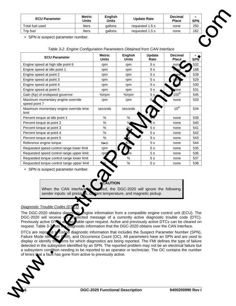
3-6 DGC-2020 Functional Description 9400200990 Rev I
ECU Parameter Metric Units
English Units Update Rate Decimal
Place ∗
SPN Total fuel used liters gallons requested 1.5 s none 250 Trip fuel liters gallons requested 1.5 s none 182
∗ SPN is suspect parameter number.
Table 3-2. Engine Configuration Parameters Obtained from CAN Interface
ECU Parameter Metric Units
English Units
Update Rate
Decimal Place
∗ SPN
Engine speed at high idle point 6 rpm rpm 5 s none 532 Engine speed at idle point 1 rpm rpm 5 s none 188 Engine speed at point 2 rpm rpm 5 s none 528 Engine speed at point 3 rpm rpm 5 s none 529 Engine speed at point 4 rpm rpm 5 s none 530 Engine speed at point 5 rpm rpm 5 s none 531 Gain (Kp) of endspeed governor %/rpm %/rpm 5 s 100th 545 Maximum momentary engine override speed point 7
rpm rpm 5 s none 533
Maximum momentary engine override time limit
seconds seconds 5 s 10th 534
Percent torque at idle point 1 % % 5 s none 539 Percent torque at point 2 % % 5 s none 540 Percent torque at point 3 % % 5 s none 541 Percent torque at point 4 % % 5 s none 542 Percent torque at point 5 % % 5 s none 543 Reference engine torque N•m ft-lb 5 s none 544 Requested speed control range lower limit rpm rpm 5 s none 535 Requested speed control range upper limit rpm rpm 5 s none 536 Requested torque control range lower limit % % 5 s none 537 Requested torque control range upper limit % % 5 s none 538
∗ SPN is suspect parameter number.
Diagnostic Trouble Codes (DTCs) The DGC-2020 obtains diagnostic engine information from a compatible engine control unit (ECU). The DGC-2020 will receive an unsolicited message of a currently active diagnostic trouble code (DTC). Previously active DTCs are available upon request. Active and previously active DTCs can be cleared on request. Table 3-3 lists the diagnostic information that the DGC-2020 obtains over the CAN interface. DTCs are reported in coded diagnostic information that includes the Suspect Parameter Number (SPN), Failure Mode Identifier (FMI), and Occurrence Count (OC). All parameters have an SPN and are used to display or identify the items for which diagnostics are being reported. The FMI defines the type of failure detected in the subsystem identified by an SPN. The reported problem may not be an electrical failure but a subsystem condition needing to be reported to an operator or technician. The OC contains the number of times that a fault has gone from active to previously active.
CAUTION When the CAN interface is enabled, the DGC-2020 will ignore the following sender inputs: oil pressure, coolant temperature, and magnetic pickup.
www . El
ectric
alPar
tMan
uals
. com

9400200990 Rev I DGC-2020 Functional Description 3-7
Table 3-3. Diagnostic Information Obtained Over the CAN Interface
Parameter Transmission
Repetition Rate Active diagnostic trouble code 1 s Lamp status 1 s Previously active diagnostic trouble code On request Request to clear active DTCs On request Request to clear previously active DTCs On request
MTU MDEC ECU Fault Codes A DGC-2020 connected to a genset equipped with an MTU MDEC engine controller tracks and displays the active fault codes issued by the MDEC ECU. Active MDEC ECU fault codes can be viewed through BESTCOMSPlus by using the Metering Explorer to expand the MTU MDEC tree or through the front panel display by navigating to METERING, ALARMS-STATUS, MDEC FAULT CODES. Each fault code is displayed with a fault description and the fault number. If the DGC-2020 does not have descriptive information about a fault number that was received, the fault description will display as “NO TEXT AVAILABLE”. For more detailed information, refer to your MDEC ECU documentation. 3, L1 T-FUEL 5, L1 T-CHRG AIR 9, L1 T-INTERCOOLER 15, L1 P-LUBE OIL 16, L2 P-LUBE OIL 19, L1 T-EXHAUST A 21, L1 T-EXHAUST B 23, L1 COOLANT LEVEL 24, L2 COOLANT LEVEL 30, ENGINE OVERSPEED 31, CHRGR1 OVERSPD 1 32, CHRGR1 OVERSPD 2 33, L1 P-FUELFLT DIF 44, L1 LEVEL INTRCLR 45, L2 LEVEL INTRCLR 51, L1 T-LUBE OIL 57, L1 P-COOLANT 58, L2 P-COOLANT 63, L1 P-CRANKCASE 65, L1 P-FUEL 67, L1 T-COOLANT 68, L2 T-COOLANT 69, L1 T-EXTERN 1 70, L2 T-EXTERN 1 71, L1 T-EXTERN 2 72, L2 T-EXTERN 2 73, L1 P-EXTERN 1 74, L2 P-EXTERN 1 75, L1 P-EXTERN 2 76, L2 P-EXTERN 2 77, LIN EXT CLNT LEV 78, LIN INTERCLR LEV 79, L BIN-EXTERN 3 80, L BIN-EXTERN 4 90, IDLE SPEED LOW 91, RUNUP SPEED LOW 92, START SPEED LOW 93, PREHT TMP. LIM 2 94, PREHT TMP. LIM 1 100, EDM NOT VALID 101, IDM NOT VALID
102, INVLD FUEL CNS 1 103, INVLD FUEL CNS 2 104, OP HRS1 INVALID 105, OP HRS2 INVALID 106, ERR REC1 INVALID 107, ERR REC2 INVALID 118, L1 SPPLY VOLT LO 119, L2 SPPLY VOLT LO 120, L1 SPPLY VOLT HI 121, L2 SPPLY VOLT HI 122, L1 T-ELECTRONIC 134, 15V POSECU DEFCT 136, 15V NEGECU DEFCT 137, L1 5V BUFFR TEST 138, SENSOR PWR DEFCT 139, L1 TE BUFFR TEST 140, TE BUF ECU DEFCT 142, BANK1ECU DEFECT 144, BANK2ECU DEFECT 145, 15V GOODECU DFCT 147, AD-TST1ECU DEFCT 149, AD-TST2ECU DEFCT 151, AD-TST3ECU DEFCT 170, MI MODULE FAIL 171, MI NOT ACTIVE 172, TBO EXPIRED 173, MODL WRITE LIMIT 180, CAN1 NODE LOST 181, CAN2 NODE LOST 183, CAN NO PU-DATA 184, CAN PUDATA EE-FL 185, CAN LESS MAILBXS 186, CAN1 BUS OFF 187, CAN1 ERROR PASSV 188, CAN2 BUS OFF 189, CAN2 ERROR PASSV 201, SD T-COOLANT 202, SD T-FUEL 203, SD T-CHARGE AIR 205, SD T-CLNT INTERC 208, SD P-CHARGE AIR
211, SD P-LUBE OIL 214, SD P-CRANKCASE 215, SD P-RAIL FUEL 216, SD T-LUBE OIL 220, SD COOLANT LEVEL 222, SD LVL LKG FUEL 223, SD LVL INTERCLR 230, SD CRANKSHFT SPD 231, SD CAMSHAFT SPD 245, SD POWER SUPPLY 246, SD T-ELECTRONIC 249, SD CAN STOP 250, SD CAN SPD DEMND 251, SD CAN UP/DOWN 252, SD CAN NOTCH POS 253, SD CAN OVERRIDE 254, SD CAN TST OVRSP 260, SD 15V POS SPPLY 261, SD 15V NEG SPPLY 262, SD 5V BUFFR TEST 263, SD TE BUFFR TEST 264, SD BANK 1 TEST 265, SD BANK 2 TEST 266, SD SPD DEMAND AN 267, SD SPDMTEST BNCH 269, SD LOAD PLS ANLG 271, SD T-EXTERN 1 272, SD T-EXTERN 2 273, SD P-EXTERN 1 274, SD P-EXTERN 2 275, MD EXT.CLNT LVL 276, MD INTERCLER LVL 277, MISDATA BIN-EXT3 278, MISDATA BIN-EXT4 279, SD CANRES TRIPFL 280, SD CAN ALRM RST 281, SD ADTEST1 SPPLY 282, SD ADTEST2 SPPLY 283, SD ADTEST3 SPPLY 284, SD CAN LAMP TEST
www . El
ectric
alPar
tMan
uals
. com

3-8 DGC-2020 Functional Description 9400200990 Rev I
RS-485 (Optional) DGC-2020 controllers with the optional RS-485 communication port (style number xxxRxxxxx) can be monitored and controlled via a polled network using the Modbus® protocol. The RS-485 port supports a user-selectable baud rate of 1200, 2400, 4800, or 9600. Odd, even, or no parity is supported. Fixed communication settings include the number of data bits (8) and stop bits (1). Modbus register values for the DGC-2020 are listed and defined in Appendix B, Modbus Communication. RS-485 port connections are made at DGC-2020 terminals 14 (485A), 13 (485B), and 12 (485 SHIELD).
Modem (Optional) When equipped with the optional, internal, dial-out modem, the DGC-2020 can be connected to a standard telephone line through its RJ-11 jack. The modem enables the DGC-2020 to dial up to four pager telephone numbers and annunciate conditions selected by the user. These conditions include any DGC-2020 alarm or pre-alarm, closure of any programmable contact input, and an active cooldown timer. The modem accommodates pagers that use seven data bits with even parity or modems using eight data bits with no parity.
Output Contacts Output contact operation is controlled by the operating mode of the DGC-2020. The state of the Emergency Stop contact input also affects output contact operation. When the Emergency Stop contact input is open (emergency stop condition), the Pre-Start, Crank, and Fuel outputs open. When the Emergency Stop input is closed, all output contacts operate normally. DGC-2020 output contacts include Pre-Start, Crank, Fuel, and up to 12 standard programmable outputs. Additional output contacts can be accommodated with a CEM-2020 (Contact Expansion Module).
Pre-Start This output closes to energize the engine glow plugs. The Pre-Start output can be programmed to close up to 30 seconds prior to engine cranking. The Pre-Start output can also be programmed to open upon engine startup or remain closed as long as the engine is operating. During the resting state, the Pre-Start can be set to Off, On, or Preheat Before Crank. If Preheat Before Crank is selected, the Pre-Start output will be closed for a time equal to the Pre-crank delay time prior to re-entering the cranking state. If the Pre-crank delay setting is longer than the rest interval, the Pre-Start output will be closed for the entire rest time. Pre-Start output connections are made through terminals located on the Pre-Start relay.
Crank This output closes when engine cranking is initiated by the DGC-2020 and opens when the magnetic pickup (MPU) or generator frequency indicates that the engine has started. Prior to engine starting, the duration of cranking is determined by the cranking style (cycle or continuous) selected. Cycle cranking permits up to 7 crank cycles with crank cycle duration of 5 to 15 seconds. The continuous crank time is adjustable from 1 to 60 seconds. Crank output connections are made through terminals located on the Crank relay.
Fuel This output closes when engine cranking is initiated by the DGC-2020. The Fuel output remains closed until an off command or emergency stop command is received. Fuel output connections are made through terminals located on the Fuel relay.
Programmable DGC-2020 controllers with a style number of xxAxxxxxx have four programmable output contacts (OUT 1 through 4). Twelve programmable outputs (OUT 1 through 12) are provided on controllers with a style number of xxBxxxxxx.
BREAKER MANAGEMENT
Introduction The DGC-2020 is capable of controlling the generator breaker and the mains breaker. Once it is determined that a valid breaker request is available, the DGC-2020 will attempt to operate the breaker if possible. The user can choose to control only the generator breaker, the generator and mains breakers,
www . El
ectric
alPar
tMan
uals
. com

9400200990 Rev I DGC-2020 Functional Description 3-9
or none. BESTCOMSPlus is used to configure breaker management. Refer to Section 4, BESTCOMSPlus Software, Breaker Management, for setting information.
Determining Breaker Status The status of the breakers is determined by using BESTlogic+ Programmable Logic to setup the GENBRK and MAINSBRK logic blocks. These logic blocks have outputs that can be configured to energize an output contact and control a breaker as well as inputs for breaker control and status.
Processing Breaker Requests Types of breaker operate requests include: • Local Request - generated by internal functions and based on operating modes. • Com Request - generated through a communication port using BESTCOMSPlus or the front panel
HMI. • Logic Request - generated from the PLC (programmable logic controller).
The type of response given for a local request depends on the operating mode of the DGC-2020.
RUN Mode When in RUN mode, the generator and mains breakers can be closed manually using contact inputs or the breaker buttons on the BESTCOMSPlus Control screen.
OFF or AUTO Mode (Not Running) If operating in the OFF mode or AUTO and not running, the generator breaker cannot be closed because the generator will not be stable.
AUTO Mode (Running) When in AUTO mode and running, the mains fail transfer feature will automatically control the mains breaker and the generator breaker or the external ATS (automatic transfer switch) will start the generator and control the breakers itself. In addition, the generator breaker can be automatically controlled by the demand start/stop function, the exercise timer function, or a RUNWLOAD (run with load) start from the PLC. The generator breaker can be manually controlled using contact inputs and outputs or the breaker buttons on the BESTCOMSPlus Control screen.
Breaker Operation The DGC-2020 will attempt to close a breaker only after verifying that it can be closed. If the breaker cannot be closed, the close request will be ignored. Only one breaker can be closed at a time. Synchronization is required before closing the breaker to a live bus. Closure to a dead bus can be performed after meeting dead bus threshold and timing requirements set by the user.
Determining if it is Acceptable to Close a Breaker Before the generator breaker can be closed, it must be configured in BESTCOMSPlus. If only the generator breaker is configured (mains breaker not configured) the DGC-2020 looks at user settings to determine if the generator side of the breaker is stable and the bus side is stable or dead. If both the generator and the mains breakers are configured and open, the DGC-2020 will close the generator breaker if the generator side of the breaker is stable. If both breakers are configured and the mains breaker is closed, the DGC-2020 will close the generator breaker after verifying that both sides of the generator breaker are stable and the DGC-2020 is synchronizing. Before the mains breaker can be closed, it must be configured in BESTCOMSPlus. If both the mains and the generator breakers are configured and open, the DGC-2020 will close the mains breaker if the mains side of the breaker is stable. If both breakers are configured and the generator breaker is closed, the DGC-2020 will close the mains breaker after verifying that both sides of the mains breaker are stable.
Changing the Breaker State Synchronization is required when closing a breaker to a live bus. Bus conditions act as a supervisory control over the synchronizing function. If synchronization is in process and either bus goes unstable, synchronization is suspended. To close the breaker on a dead bus, the DGC-2020 generates a breaker close request. The closing function is then run without synchronization.
www . El
ectric
alPar
tMan
uals
. com

3-10 DGC-2020 Functional Description 9400200990 Rev I
The GENBRK and MAINSBRK logic blocks contain both Open and Close logic outputs that can be configured to energize an output contact, which would in turn operate the breaker. The Synchronizer screen in BESTCOMSPlus is used to set the output contact type to pulses or continuous.
EVENT RECORDING An event log retains history of system events in nonvolatile memory. Thirty event records are retained and each record contains a time stamp of the first and last event occurrence, and the number of occurrences for each event. In addition, each record contains details of the time, date, and engine hours for the most recent 30 occurrences of the event. The number of occurrences stops incrementing at 99. If an event occurs which is of a type that differs from those in the 30 records in memory, the record that has the oldest “last” event occurrence is removed from the log, and the new category takes its place. Since 30 event records with up to 99 occurrences each are retained in memory, a history of nearly 3,000 specific events are retained in the DGC-2020. Detailed occurrence information is retained for the most recent 30 occurrences of each event record, and there are 30 event records; thus the time, date, and engine hours details for up to 900 specific event occurrences are retained in the event log. BESTCOMSPlus can be used to view and/or download the event log. The event log may also be viewed through the front panel HMI by navigating to Metering, Alarms-Status, Event Log. Use the Up/Down keys to highlight an event and press the Right key to view the summary of that event record. The summary contains the description of the event, the date, time, and engine hours of the first occurrence of the event, along with date, time, and engine hours of the most recent occurrence of the event. To view details of specific event occurrences, press the Down key until DETAILS is highlighted and then press the Right key. The occurrence number can be changed by pressing the Edit key, Up/Down keys to select #, and pressing the Edit key again to exit. Table 3-4 lists all possible event strings (as shown in the event log).
Table 3-4. Event List
Event String Event Description Event Type
27-1_TRIP_A 27-1 Undervoltage Trip Alarm 27-1_TRIP_P 27-1 Undervoltage Trip Pre-Alarm 27-2_TRIP_A 27-2 Undervoltage Trip Alarm 27-2_TRIP_P 27-2 Undervoltage Trip Pre-Alarm 32_TRIP_A 32 Reverse Power Trip Alarm 32_TRIP_P 32 Reverse Power Trip Pre-Alarm 40_TRIP_A 40 Loss of Excitation Trip Alarm 40_TRIP_P 40 Loss of Excitation Trip Pre-Alarm 47_TRIP_A 47 Phase Imbalance Trip Alarm 47_TRIP_P 47 Phase Imbalance Trip Pre-Alarm 51-1_TRIP_A 51-1 Overcurrent Trip Alarm 51-1_TRIP_P 51-1 Overcurrent Trip Pre-Alarm 51-2_TRIP_A 51-2 Overcurrent Trip Alarm 51-2_TRIP_P 51-2 Overcurrent Trip Pre-Alarm 59-1_TRIP_A 59-1 Overvoltage Trip Alarm 59-1_TRIP_P 59-1 Overvoltage Trip Pre-Alarm 59-2_TRIP_A 59-2 Overvoltage Trip Alarm 59-2_TRIP_P 59-2 Overvoltage Trip Pre-Alarm 81O_TRIP_A 81 Overfrequency Trip Alarm 81O_TRIP_P 81 Overfrequency Trip Pre-Alarm 81U_TRIP_A 81 Underfrequency Trip Alarm 81U_TRIP_P 81 Underfrequency Trip Pre-Alarm ATS INPUT CLOSED ATS Input Status
www . El
ectric
alPar
tMan
uals
. com

9400200990 Rev I DGC-2020 Functional Description 3-11
Event String Event Description Event Type
AUTO_RESTART_FAIL_A Automatic Restart Fail Alarm AUTO_RESTART_IN_PROGRESS Automatic Restart in Progress Status BATT_CHRG_FAIL_A Battery Charger Fail Alarm BATT_CHRG_FAIL_P Battery Charger Fail Pre-Alarm BATT_OVERVOLT_P Battery Overvoltage Pre-Alarm BATTLE OVERRIDE Battle Override Status CEM_COMM_FAIL_P CEM-2020 Communications Failure Pre-Alarm CONFIG_ELEMENT_N_A (where N is a number in the range of 1 to 8)
Configurable Element N (where N is a number in the range of 1 to 8) Alarm
CONFIG_ELEMENT_N_P (where N is a number in the range of 1 to 8)
Configurable Element N (where N is a number in the range of 1 to 8) Pre-Alarm
COOL_SNDR_FAIL Coolant Temperature Sender Fail Status COOL_SNDR_FAIL_A Coolant Temperature Sender Fail Alarm COOL_SNDR_FAIL_P Coolant Temperature Sender Fail Pre-Alarm DIAG_TRBL_CODE_P Diagnostic Trouble Code Pre-Alarm DIAL_OUT_FAIL Modem Dialout Failed Status DIAL_OUT_SUCCESS Modem Dialout Success Status ECU_SHUTDOWN_A ECU Shutdown Alarm EMERGENCY_STOP_A Emergency Stop Alarm ENG_KW_OVERLOAD1_P Engine KW Overload 1 Pre-Alarm ENG_KW_OVERLOAD2_P Engine KW Overload 2 Pre-Alarm ENG_KW_OVERLOAD3_P Engine KW Overload 3 Pre-Alarm ENGINE_RUNNING Engine Running Status FUEL_LEAK_DETECT_A Fuel Leak Detect Alarm FUEL_LEAK_DETECT_P Fuel Leak Detect Pre-Alarm FUEL_LVL_SNDR Fuel Level Sender Fail Status FUEL_LVL_SNDR_A Fuel Level Sender Fail Alarm FUEL_LVL_SNDR_P Fuel Level Sender Fail Pre-Alarm GENTEST Generator Exerciser Test Status GENTESTLOADED Generator Exerciser Test with Load Status GLBL_SNDR_FAIL_A Global Sender Fail Alarm GN_BKR_CL_FL_P Generator Breaker Fail to Close Pre-Alarm GN_BKR_OP_FL_P Generator Breaker Fail to Open Pre-Alarm GN_BKR_SYN_FL_P Generator Breaker Synchronization Fail Pre-Alarm HI_COOLANT_TMP_A High Coolant Temp Alarm HI_COOLANT_TMP_P High Coolant Temp Pre-Alarm HIGH_FUEL_LEVEL_P High Fuel Level Pre-Alarm ID_MISSING_P LSM-2020 ID Missing Pre-Alarm ID_REPEAT_P LSM-2020 ID Repeated Pre-Alarm INPUT_N_A (where N is a number in the range of 1 to 40)
User Configurable Input N (where N is a number in the range of 1 to 40) Alarm
INPUT_N_P (where N is a number in the range of 1 to 40)
User Configurable Input N (where N is a number in the range of 1 to 40) Pre-Alarm
www . El
ectric
alPar
tMan
uals
. com

3-12 DGC-2020 Functional Description 9400200990 Rev I
Event String Event Description Event Type
LOGIC OUPUT_A Logic Output Alarm LOGIC OUPUT_P Logic Output Pre-Alarm LOSS_OF_VOLT Voltage Sensing Fail Status LOSS_OF_VOLT_A Voltage Sensing Fail Alarm LOSS_OF_VOLT_P Voltage Sensing Fail Pre-Alarm LOSS_REM_COMS_P Loss of Remote Module Communications Pre-Alarm LOST_ECU_COMM_A Loss of ECU Communication Alarm LOST_ECU_COMM_P Loss of ECU Communication Pre-Alarm LOW_BATT_VOLT_P Low Coolant Level Alarm LOW_COOL_TMP_A Low Coolant Level Alarm LOW_COOL_TMP_P Low Coolant Level Pre-Alarm LOW_FUEL_LEVEL_A Low Fuel Level Alarm LOW_FUEL_LEVEL_P Low Fuel Level Pre-Alarm LOW_OIL_PRES_A Low Oil Pressure Alarm LOW_OIL_PRES_P Low Oil Pressure Pre-Alarm LSM_AVR_OUT_LMT_P LSM-2020 AVR Output Limit Pre-Alarm LSM_COMMS_FAIL_P LSM-2020 Communications Failure Pre-Alarm LSM_GOV_OUT_LMT_P LSM-2020 GOV Output Limit Pre-Alarm LSM_INTERGEN_COM_FAIL_P LSM-2020 Intergen Communications Failure Pre-Alarm MAINT_INTERVAL_P Maintenance Interval Pre-Alarm MF_TRANSFER Mains Fail Transfer Complete Status MF_TRANSFER_FAIL Mains Fail Transfer Fail Status MN_BKR_CL_FL_P Mains Breaker Fail to Close Pre-Alarm MN_BKR_OP_FL_P Mains Breaker Fail to Open Pre-Alarm MN_BKR_SYN_FL_P Mains Breaker Synchronization Fail Pre-Alarm MPU_FAIL_P Magnetic Pickup Fail Pre-Alarm MULTIPLE_CEM_P Multiple CEM-2020’s Pre-Alarm MULTIPLE_LSM_P Multiple LSM-2020’s Pre-Alarm NORM_SHUTDOWN Normal Shutdown Status OIL PRESS SENDR FAIL Oil Pressure Sender Fail Status OIL PRESS SENDR FAIL_A Oil Pressure Sender Fail Alarm OIL PRESS SENDR FAIL_P Oil Pressure Sender Fail Pre-Alarm OVERCRANK_A Overcrank Alarm PROT_SHUTDOWN Protective Shutdown Status SPD_SNDR_FAIL Speed Sender Fail Status SPD_SNDR_FAIL_A Speed Sender Fail Alarm WEAK_BATTERY_P Weak Battery Pre-Alarm
www . El
ectric
alPar
tMan
uals
. com

9400200990 Rev I DGC-2020 BESTCOMSPlus Software i
SECTION 4 • BESTCOMSPlus SOFTWARE TABLE OF CONTENTS
SECTION 4 • BESTCOMSPlus SOFTWARE ........................................................................................... 4-1
INTRODUCTION.................................................................................................................................... 4-1 INSTALLATION...................................................................................................................................... 4-1
Installing BESTCOMSPlus ................................................................................................................. 4-2 STARTUP AND ACTIVATION............................................................................................................... 4-2
Starting BESTCOMSPlus................................................................................................................... 4-2 Activating the DGC-2020 Plug-In ....................................................................................................... 4-3
COMMUNICATION................................................................................................................................ 4-4 Connecting the DGC-2020 and PC.................................................................................................... 4-4 Configuring Communication ............................................................................................................... 4-4 Installing the USB Driver if Automatic Installation Fails ..................................................................... 4-5 Establishing Communication .............................................................................................................. 4-5
MENU BARS.......................................................................................................................................... 4-6 Upper Menu Bar (BESTCOMSPlus Shell) ......................................................................................... 4-6 Lower Menu Bar (DGC-2020 Plug-In)................................................................................................ 4-7
SETTINGS EXPLORER ........................................................................................................................ 4-7 DGC-2020 AND SYSTEM PARAMETERS ........................................................................................... 4-7 GENERAL SETTINGS........................................................................................................................... 4-7
Front Panel HMI ................................................................................................................................. 4-8 Style Number...................................................................................................................................... 4-8 Device Info.......................................................................................................................................... 4-8 Device Security Setup ...................................................................................................................... 4-10 Clock Setup ...................................................................................................................................... 4-11
COMMUNICATIONS ........................................................................................................................... 4-12 CANBus Setup ................................................................................................................................. 4-12 Modem Setup (Optional) .................................................................................................................. 4-14 RS-485 Setup (Optional) .................................................................................................................. 4-16
SYSTEM PARAMETERS .................................................................................................................... 4-17 System Settings ............................................................................................................................... 4-17 Crank Settings.................................................................................................................................. 4-19 Automatic Restart ............................................................................................................................. 4-20 Exercise Timer.................................................................................................................................. 4-21 Sensing Transformers ...................................................................................................................... 4-22
PROGRAMMABLE INPUTS................................................................................................................ 4-22 Configurable Local Inputs................................................................................................................. 4-22 Programmable Functions ................................................................................................................. 4-23 Configurable Remote Inputs............................................................................................................. 4-24
PROGRAMMABLE OUTPUTS............................................................................................................ 4-25 Configurable Local Outputs.............................................................................................................. 4-25 Configurable Elements ..................................................................................................................... 4-25 Configurable Remote Outputs.......................................................................................................... 4-26
ALARM CONFIGURATION ................................................................................................................. 4-27 Pre-Alarms........................................................................................................................................ 4-27 Alarms .............................................................................................................................................. 4-31 Sender Fail ....................................................................................................................................... 4-32
GENERATOR PROTECTION.............................................................................................................. 4-33 Voltage Protection (27, 59, 47)......................................................................................................... 4-33 Frequency Protection (81O/U) ......................................................................................................... 4-36 Reverse Power Protection (32) ........................................................................................................ 4-36 Loss of Excitation Protection (40Q).................................................................................................. 4-37 Overcurrent Protection (51-1, 51-2) ................................................................................................. 4-38
BREAKER MANAGEMENT................................................................................................................. 4-40 Breaker Hardware ............................................................................................................................ 4-40 Bus Condition Detection................................................................................................................... 4-42 Automatic Synchronizer (Optional) .................................................................................................. 4-43
www . El
ectric
alPar
tMan
uals
. com

ii DGC-2020 BESTCOMSPlus Software 9400200990 Rev I
BIAS CONTROL SETTINGS ............................................................................................................... 4-44 AVR Bias Control Settings ............................................................................................................... 4-44 Governor Bias Control Settings........................................................................................................ 4-45 PID Controller ................................................................................................................................... 4-47
MULTIGEN MANAGEMENT................................................................................................................ 4-48 AVR Output ...................................................................................................................................... 4-48 Governor Output............................................................................................................................... 4-48 Load Share Output ........................................................................................................................... 4-49 Demand Start/Stop........................................................................................................................... 4-49 Generator Sequencing ..................................................................................................................... 4-50 Network Configuration...................................................................................................................... 4-51
PROGRAMMABLE SENDERS............................................................................................................ 4-52 BESTlogic+ PROGRAMMABLE LOGIC.............................................................................................. 4-53
Logic Timers ..................................................................................................................................... 4-53 FILE MANAGEMENT........................................................................................................................... 4-53
Settings Files .................................................................................................................................... 4-53 Uploading Device Packages (Firmware/Language Module)............................................................ 4-55
METERING EXPLORER ..................................................................................................................... 4-57 Engine .............................................................................................................................................. 4-59 Generator ......................................................................................................................................... 4-59 Power ............................................................................................................................................... 4-59 Run Statistics.................................................................................................................................... 4-60 Status ............................................................................................................................................... 4-60 Inputs................................................................................................................................................ 4-61 Outputs ............................................................................................................................................. 4-62 Alarms .............................................................................................................................................. 4-64 Event Log ......................................................................................................................................... 4-64 J1939 ECU ....................................................................................................................................... 4-66 MTU MDEC ...................................................................................................................................... 4-68 Summary .......................................................................................................................................... 4-69 Control .............................................................................................................................................. 4-70 Real Time Clock ............................................................................................................................... 4-70 Generator Network Status................................................................................................................ 4-71
UPDATING BESTCOMSPlus SOFTWARE......................................................................................... 4-71 CONVERTING SETTINGS FILES....................................................................................................... 4-71
Figures Figure 4-1. Typical User Interface Components........................................................................................ 4-1 Figure 4-2. BESTCOMSPlus Select Language......................................................................................... 4-2 Figure 4-3. Splash Screen......................................................................................................................... 4-3 Figure 4-4. Communication Pull-Down Menu............................................................................................ 4-3 Figure 4-5. Device Needs Activated .......................................................................................................... 4-4 Figure 4-6. DGC-2020 Connection............................................................................................................ 4-5 Figure 4-7. Processing, Please Wait…...................................................................................................... 4-5 Figure 4-8. Front Panel HMI Settings ........................................................................................................ 4-8 Figure 4-9. DGC-2020 Style Chart Selections and Definitions ................................................................. 4-8 Figure 4-10. Device Info Values and Settings ........................................................................................... 4-9 Figure 4-11. Device Security Setup......................................................................................................... 4-11 Figure 4-12. Clock Setup......................................................................................................................... 4-12 Figure 4-13. CANBus Setup .................................................................................................................... 4-14 Figure 4-14. Modem Setup...................................................................................................................... 4-16 Figure 4-15. RS-485 Setup...................................................................................................................... 4-17 Figure 4-16. System Settings .................................................................................................................. 4-19 Figure 4-17. Engine Crank Settings ........................................................................................................ 4-20 Figure 4-18. Automatic Restart Settings.................................................................................................. 4-21 Figure 4-19. Exercise Timer Settings ...................................................................................................... 4-21 Figure 4-20. Sensing Transformers Parameters ..................................................................................... 4-22 Figure 4-21. Configurable Inputs Settings............................................................................................... 4-23 Figure 4-22. Programmable Functions Settings...................................................................................... 4-24 Figure 4-23. Configurable Remote Inputs Settings ................................................................................. 4-25 Figure 4-24. Configurable Outputs Settings ............................................................................................ 4-25
www . El
ectric
alPar
tMan
uals
. com

9400200990 Rev I DGC-2020 BESTCOMSPlus Software iii
Figure 4-25. Configurable Elements Settings.......................................................................................... 4-26 Figure 4-26. Configurable Remote Outputs Settings .............................................................................. 4-26 Figure 4-27. Pre-Alarms Configuration.................................................................................................... 4-30 Figure 4-28. Alarms Configuration........................................................................................................... 4-32 Figure 4-29. Sender Fail Configuration ................................................................................................... 4-33 Figure 4-30. Undervoltage Protection Settings ....................................................................................... 4-34 Figure 4-31. Overvoltage Protection Settings ......................................................................................... 4-35 Figure 4-32. Phase Imbalance Protection Settings ................................................................................. 4-35 Figure 4-33. Frequency Protection Settings............................................................................................ 4-36 Figure 4-34. Reverse Power Protection Settings .................................................................................... 4-37 Figure 4-35. Generator Capability Curve vs. 40Q Response.................................................................. 4-38 Figure 4-36. Loss of Excitation Protection Settings................................................................................. 4-38 Figure 4-37. Overcurrent Protection Settings.......................................................................................... 4-40 Figure 4-38. Breaker Hardware Settings................................................................................................. 4-41 Figure 4-39. Bus Condition Detection Settings ....................................................................................... 4-42 Figure 4-40. Synchronizer Settings ......................................................................................................... 4-44 Figure 4-41. AVR Bias Control Settings .................................................................................................. 4-45 Figure 4-42. Governor Bias Control Settings .......................................................................................... 4-47 Figure 4-43. AVR Output Settings........................................................................................................... 4-48 Figure 4-44. Governor Output Settings ................................................................................................... 4-49 Figure 4-45. Load Share Output.............................................................................................................. 4-49 Figure 4-46. Demand Start/Stop.............................................................................................................. 4-50 Figure 4-47. Generator Sequencing........................................................................................................ 4-51 Figure 4-48. Network Configuration Settings .......................................................................................... 4-52 Figure 4-49. Programmable Senders Settings ........................................................................................ 4-53 Figure 4-50. BESTCOMSPlus Settings Compare Setup......................................................................... 4-54 Figure 4-51. BESTCOMSPlus Settings Compare ................................................................................... 4-55 Figure 4-52. Basler Electric Device Package Uploader .......................................................................... 4-56 Figure 4-53. DGC-2020 Selection ........................................................................................................... 4-56 Figure 4-54. Processing, Please Wait… ................................................................................................. 4-56 Figure 4-55. Metering, Docking Options.................................................................................................. 4-58 Figure 4-56. Metering, Engine ................................................................................................................. 4-59 Figure 4-57. Metering, Generator ............................................................................................................ 4-59 Figure 4-58. Metering, Power .................................................................................................................. 4-59 Figure 4-59. Metering, Run Statistics ...................................................................................................... 4-60 Figure 4-60. Metering, Status .................................................................................................................. 4-60 Figure 4-61. Metering, Inputs, Configurable Local Inputs ....................................................................... 4-61 Figure 4-62. Metering, Inputs, Configurable Remote Inputs ................................................................... 4-61 Figure 4-63. Metering, Outputs, Configurable Local Outputs.................................................................. 4-62 Figure 4-64. Metering, Outputs, Configurable Elements......................................................................... 4-62 Figure 4-65. Metering, Outputs, Configurable Remote Outputs.............................................................. 4-63 Figure 4-66. Metering, Alarms................................................................................................................. 4-64 Figure 4-67. Metering, Event Log, Sorted by Date.................................................................................. 4-65 Figure 4-68. Metering, Event Log, Sorted by Event ID............................................................................ 4-66 Figure 4-69. Metering, ECU Data............................................................................................................ 4-66 Figure 4-70. Metering, Engine Configuration .......................................................................................... 4-67 Figure 4-71. Metering, Download DTC.................................................................................................... 4-67 Figure 4-72. Metering, MDEC Alarms ..................................................................................................... 4-68 Figure 4-73. Metering, MDEC Fault Codes ............................................................................................. 4-68 Figure 4-74. Metering, Summary............................................................................................................. 4-69 Figure 4-75. Metering, Control................................................................................................................. 4-70 Figure 4-76. Metering, Real Time Clock.................................................................................................. 4-70 Figure 4-77. Metering, Generator Network Status .................................................................................. 4-71
Tables Table 4-1. System Requirements for BESTCOMSPlus and the .NET Framework................................... 4-2 Table 4-2. Explanation of Call-Outs on Figure 4-55................................................................................ 4-58
www . El
ectric
alPar
tMan
uals
. com

iv DGC-2020 BESTCOMSPlus Software 9400200990 Rev I
This page intentionally left blank.
www . El
ectric
alPar
tMan
uals
. com

9400200990 Rev I DGC-2020 BESTCOMSPlus Software 4-1
SECTION 4 • BESTCOMSPlus SOFTWARE INTRODUCTION BESTCOMSPlus is a Windows®-based, PC application that provides a user-friendly, graphical user interface (GUI) for use with Basler Electric communicating products. The name BESTCOMSPlus is an acronym that stands for Basler Electric Software Tool for Communications, Operations, Maintenance, and Settings. BESTCOMSPlus provides the user with a point-and-click means to set and monitor the DGC-2020. The capabilities of BESTCOMSPlus make the configuration of one or several DGC-2020 controllers fast and efficient. A primary advantage of BESTCOMSPlus is that a settings scheme can be created, saved as a file, and then uploaded to the DGC-2020 at the user’s convenience. BESTCOMSPlus uses plug-ins allowing the user to manage several different Basler Electric products. The DGC-2020 is a plug-in for BESTCOMSPlus and must be activated before use. The DGC-2020 plug-in opens inside the BESTCOMSPlus main shell with the same default logic scheme that is shipped with the DGC-2020. This gives the user the option of developing a custom setting file by modifying the default logic scheme or by building a unique scheme from scratch. BESTlogic+ Programmable Logic is used to program DGC-2020 inputs and outputs, alarms, and generator protection functions. This is accomplished by the drag-and-drop method. The user can drag elements, components, inputs, and outputs onto the program grid and make connections between them to create the desired logic scheme. Figure 4-1 illustrates the typical user interface components of the DGC-2020 plug-in with BESTCOMSPlus.
Upper Menu Bar
Metering Explorer
Settings Explorer
Status Bar
Lower Menu Bar
Setting Information
P005
3-12
Figure 4-1. Typical User Interface Components
INSTALLATION BESTCOMSPlus software is built on the Microsoft® .NET Framework. The setup utility that installs BESTCOMSPlus on your PC also installs the DGC-2020 plug-in and the .NET Framework (if not already installed). BESTCOMSPlus operates with IBM-compatible personal computers (PCs) using Windows® 2000, Windows® XP, and Windows® Vista. Microsoft® Internet Explorer 5.01 or later must be installed on your PC before installing BESTCOMSPlus. System requirements for the .NET Framework and BESTCOMSPlus are listed in Table 4-1.
www . El
ectric
alPar
tMan
uals
. com

4-2 DGC-2020 BESTCOMSPlus Software 9400200990 Rev I
Table 4-1. System Requirements for BESTCOMSPlus and the .NET Framework
Component Requirement Processor 400 MHz RAM 128 MB
25 MB (if .NET Framework is already installed on PC.) Hard Drive
250 MB (if .NET Framework is not already installed on PC.)
In order to install and run BESTCOMSPlus, a Windows user must have administrator rights. A Windows user with limited rights may not be permitted to save files in certain folders.
Installing BESTCOMSPlus
1. Insert the BESTCOMSPlus CD-ROM into the PC CD-ROM drive. 2. When the BESTCOMSPlus Setup and Documentation CD menu appears, click the Install button for
the BESTCOMSPlus application. The setup utility automatically installs BESTCOMSPlus, the .NET Framework (if not already installed), and the DGC-2020 plug-in for BESTCOMSPlus on your PC.
When BESTCOMSPlus installation is complete, a Basler Electric folder is added to the Windows programs menu. This folder is accessed by clicking the Windows Start button and then accessing the Basler Electric folder in the Programs menu. The Basler Electric folder contains an icon that, when clicked, starts BESTCOMSPlus.
STARTUP AND ACTIVATION
Starting BESTCOMSPlus To start BESTCOMSPlus, click the Start button, Programs, Basler Electric, and then the BESTCOMSPlus icon. During initial startup, the BESTCOMSPlus Select Language screen is displayed (Figure 4-2). You can select to have this screen displayed each time BESTCOMSPlus is started, or you can select a preferred language and this screen will be bypassed in the future. Click OK to continue. This screen can later be accessed by selecting Tools and Select Language from the menu bar.
Figure 4-2. BESTCOMSPlus Select Language
NOTE Do not connect USB cable until setup completes successfully. Connecting USB cable before setup is complete may result in unwanted or unexpected errors.
www . El
ectric
alPar
tMan
uals
. com
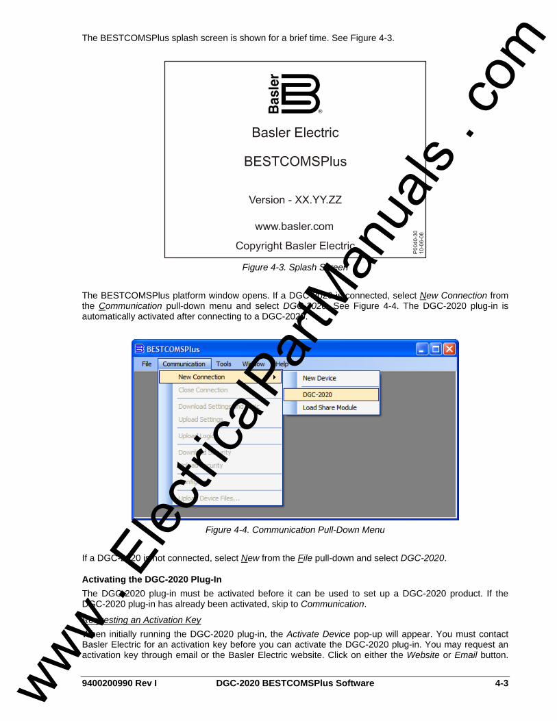
9400200990 Rev I DGC-2020 BESTCOMSPlus Software 4-3
The BESTCOMSPlus splash screen is shown for a brief time. See Figure 4-3.
Figure 4-3. Splash Screen
The BESTCOMSPlus platform window opens. If a DGC-2020 is connected, select New Connection from the Communication pull-down menu and select DGC-2020. See Figure 4-4. The DGC-2020 plug-in is automatically activated after connecting to a DGC-2020.
Figure 4-4. Communication Pull-Down Menu
If a DGC-2020 is not connected, select New from the File pull-down and select DGC-2020.
Activating the DGC-2020 Plug-In The DGC-2020 plug-in must be activated before it can be used to set up a DGC-2020 product. If the DGC-2020 plug-in has already been activated, skip to Communication.
Requesting an Activation Key When initially running the DGC-2020 plug-in, the Activate Device pop-up will appear. You must contact Basler Electric for an activation key before you can activate the DGC-2020 plug-in. You may request an activation key through email or the Basler Electric website. Click on either the Website or Email button.
www . El
ectric
alPar
tMan
uals
. com

4-4 DGC-2020 BESTCOMSPlus Software 9400200990 Rev I
Click on the Activate button when you are ready to enter the activation key you received from Basler Electric. The Device Needs Activated pop-up will appear. Refer to Figure 4-5.
Entering an Activation Key Select the device from the Device pull-down menu. Enter your Email Address and Activation Key provided by Basler Electric. If you received an email containing the Activation Key, you can select all of the text in the email and copy it to the Windows® clipboard using normal Windows® techniques. The Get Data button will extract the Device, Email Address, and Activation Key from the Windows® clipboard and paste it into the appropriate fields. Click on the Activate button to continue. The Device Needs Activated screen is also found by selecting Activate Device from the Tools pull-down menu of the BESTCOMSPlus main shell.
Figure 4-5. Device Needs Activated
COMMUNICATION Remember, you do not have to have a unit connected to the PC to operate BESTCOMSPlus and program settings. If you have an actual unit, you may connect a communication cable between the unit and the appropriate communication port on the PC. If communication is already configured, skip to Establishing Communication.
Connecting the DGC-2020 and PC Connect a communication cable between the USB or Modem connector of the DGC-2020 and the appropriate port of the PC. Refer to Section 6, Installation, for the required connections between the DGC-2020 and PC.
Configuring Communication Before communication between BESTCOMSPlus and the DGC-2020 is established, the PC communication port connected to the DGC-2020 must be configured and selected in BESTCOMSPlus. To configure the port, use the Settings Explorer to open the Communications tree branch. Open the tree branch of the communication protocol you wish to configure. Make the appropriate settings. For more information on the Communications tree branch, refer to Communications later in this section. To select the communication port, click Communication on the menu bar, followed by New Connection and DGC-2020. Select the method of communicating with the DGC-2020. If connecting to the DGC-2020 through an optional LSM-2020 (Load Share Module), select Ethernet Connection and enter the IP Address. If connecting straight to the DGC-2020 through a USB cable, select USB via Serial RS232, USB, and enter COM Port. If connecting straight to the DGC-2020 through a telephone line, select USB via Serial RS232, Modem, and enter Phone Number. See Figure 4-6.
www . El
ectric
alPar
tMan
uals
. com
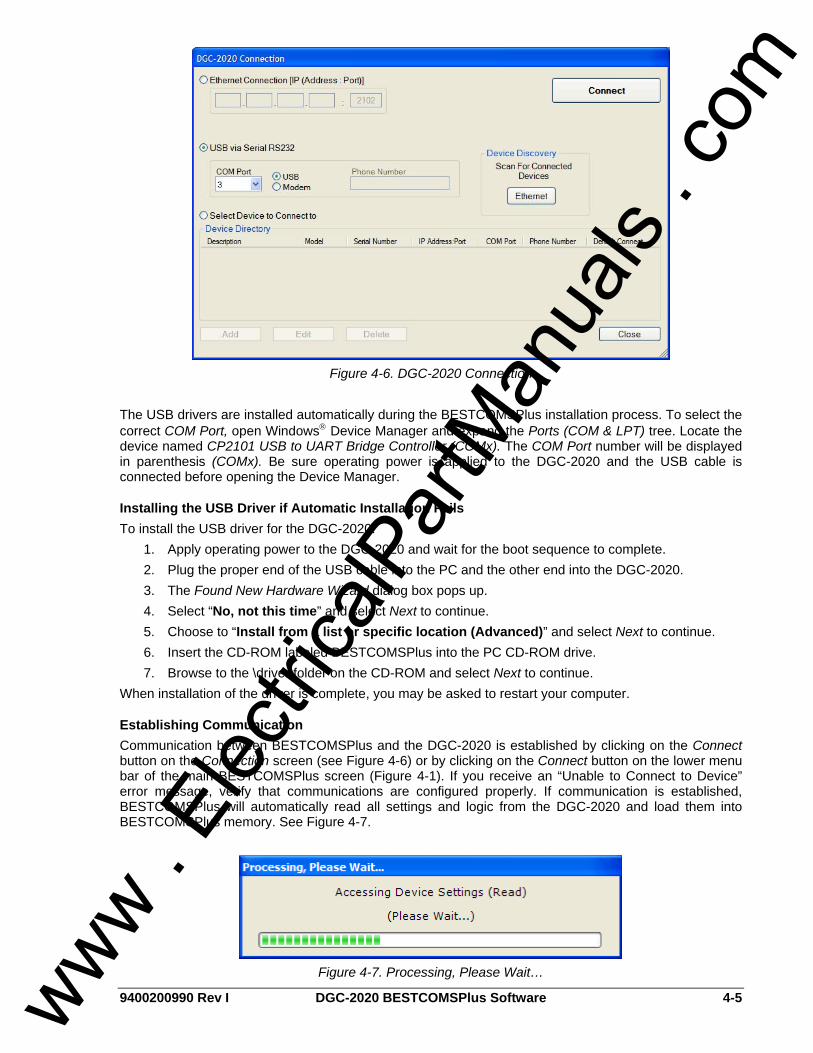
9400200990 Rev I DGC-2020 BESTCOMSPlus Software 4-5
Figure 4-6. DGC-2020 Connection
The USB drivers are installed automatically during the BESTCOMSPlus installation process. To select the correct COM Port, open Windows® Device Manager and expand the Ports (COM & LPT) tree. Locate the device named CP2101 USB to UART Bridge Controller (COMx). The COM Port number will be displayed in parenthesis (COMx). Be sure operating power is applied to the DGC-2020 and the USB cable is connected before opening the Device Manager.
Installing the USB Driver if Automatic Installation Fails To install the USB driver for the DGC-2020:
1. Apply operating power to the DGC-2020 and wait for the boot sequence to complete. 2. Plug the proper end of the USB cable into the PC and the other end into the DGC-2020. 3. The Found New Hardware Wizard dialog box pops up. 4. Select “No, not this time” and select Next to continue. 5. Choose to “Install from a list or specific location (Advanced)” and select Next to continue. 6. Insert the CD-ROM labeled BESTCOMSPlus into the PC CD-ROM drive. 7. Browse to the \driver folder on the CD-ROM and select Next to continue.
When installation of the driver is complete, you may be asked to restart your computer.
Establishing Communication Communication between BESTCOMSPlus and the DGC-2020 is established by clicking on the Connect button on the Connection screen (see Figure 4-6) or by clicking on the Connect button on the lower menu bar of the main BESTCOMSPlus screen (Figure 4-1). If you receive an “Unable to Connect to Device” error message, verify that communications are configured properly. If communication is established, BESTCOMSPlus will automatically read all settings and logic from the DGC-2020 and load them into BESTCOMSPlus memory. See Figure 4-7.
Figure 4-7. Processing, Please Wait…
www . El
ectric
alPar
tMan
uals
. com

4-6 DGC-2020 BESTCOMSPlus Software 9400200990 Rev I
MENU BARS The menu bars are located near the top of the BESTCOMSPlus screen (see Figure 4-1). The upper menu bar has five pull down menus. With the upper menu bar, it is possible to manage settings files, setup communications, upload and download settings/security files, and compare settings files. The lower menu bar consists of clickable icons. The lower menu bar is used to change BESTCOMSPlus views, open a settings file, connect/disconnect, preview metering printout, switch to live mode, and send a settings file to the DGC-2020.
Upper Menu Bar (BESTCOMSPlus Shell)
File • New ............................................................... Create a new settings file • Open.............................................................. Open an existing settings file • Open File As Text ......................................... Generic file viewer for ∗.csv, ∗.txt, etc. files • Close ............................................................. Close settings file • Save .............................................................. Save settings file • Save As......................................................... Save settings file with a different name • Print Preview ................................................. Preview a settings file printout • Print To File................................................... Save as rich text file type (∗.rtf) • Print ............................................................... Print a settings file • Properties...................................................... View properties of a settings file • History ........................................................... View history of a settings file • Recent Files .................................................. Open a previously opened file • Exit ................................................................ Close BESTCOMSPlus program
Communication • New Connection............................................ Choose new device or DGC-2020 • Close Connection.......................................... Close communication connection • Download Settings and Logic........................ Download operational and logic settings from the device • Upload Settings............................................. Upload operational settings to the device • Upload Logic ................................................. Upload logic settings to the device • Download Security ........................................ Download security settings from the device • Upload Security............................................. Upload security settings to the device • Upload Device Files ...................................... Upload a device package (firmware/language module)
Tools • Check For Updates ....................................... Check for BESTCOMSPlus updates via the internet • Select Language ........................................... Select BESTCOMSPlus language • Activate Device ............................................. Activate the product instance (DGC-2020 plug-in) • Set File Password ......................................... Password protect a settings file • Compare Settings Files................................. Compare settings files • View Event Log ............................................. View the BESTCOMSPlus event log • Clear Event Log ............................................ Clear the BESTCOMSPlus event log • Set New File Name ....................................... Set a new file name for event log
Window • Cascade All ................................................... Cascade all windows • Tile ................................................................ Tile horizontally or vertically • Maximize All .................................................. Maximize all windows
Help • About ............................................................. View general, detailed build, and system information
www . El
ectric
alPar
tMan
uals
. com

9400200990 Rev I DGC-2020 BESTCOMSPlus Software 4-7
Lower Menu Bar (DGC-2020 Plug-In)
View This clickable icon allows you to view the Metering Panel, Settings Panel, or Show Settings Information.
Open File This clickable icon is used to open a saved settings file.
Connect/Disconnect Opens the DGC-2020 Connection screen allowing the user to connect via USB or a modem. Also used to disconnect from the device.
Preview Metering Clicking on this icon will bring up the Print Preview screen where a preview of the Metering printout is shown. Click on the printer icon to send to a printer.
Options When clicked, a drop-down list appears. Live Mode Settings puts BESTCOMSPlus in Live mode where settings are automatically sent to the device in real time as they are changed.
Send Settings This button is used when BESTCOMSPlus is not operating in Live Mode. Click on this button after making a setting change to send the modified setting to the DGC-2020.
SETTINGS EXPLORER The Settings Explorer is a convenient tool within BESTCOMSPlus used to navigate through the various settings screens of the DGC-2020 plug-in as listed in the following paragraphs. Logic setup will be necessary after making certain setting changes. For more information, refer to Section 5, BESTlogic+ Programmable Logic.
DGC-2020 AND SYSTEM PARAMETERS Prior to use, the DGC-2020 must be configured for operation in the intended application. The description of these configuration settings is organized as follows: • General Settings • Communications • System Parameters • Programmable Inputs • Alarm Configuration • Generator Protection • Breaker Management • Bias Control Settings • Multigen Management • Programmable Senders • BESTlogic+ Programmable Logic
GENERAL SETTINGS General DGC-2020 settings consist of settings controlling the HMI display and indicators. Additional general settings include style number configuration, DGC-2020 identification, DGC-2020 version information, and device security setup.
NOTE In the following descriptions, superscript letters (e.g., settingX) mark words and phrases relating to DGC-2020 settings. Each letter references settings illustrated in BESTCOMSPlus. Lettered notes at the end of each group of descriptions provide the range and increment for each setting.
www . El
ectric
alPar
tMan
uals
. com

4-8 DGC-2020 BESTCOMSPlus Software 9400200990 Rev I
Front Panel HMI The contrastA of the front panel LCD (liquid crystal display) can be adjusted to suit the viewing angle used or compensate for environmental conditions. A power saving feature, referred to as Sleep modeB, will turn the front panel LCD backlight and LCD heater off when the DGC-2020 is in Off mode or Auto mode (not in Run mode) and a key is not pressed for more than 15 minutes. Normal display operation is resumed when any front panel button is pressed or the genset is started remotely via the ATS. Sleep mode is enabled and disabled in BESTCOMSPlus. Specific language modules can be uploaded into the DGC-2020. When the language module upload is complete, use the LanguageC selector to select the correct language. BESTCOMSPlus front panel HMI settings are illustrated in Figure 4-8.
Figure 4-8. Front Panel HMI Settings
A LCD Contrast Value: Adjustable from 0 to 100 (maximum contrast) in increments of 1. B Front Panel Sleep Mode: Enable or Disable. C Language: Default or Alternate.
Style Number When a PC operating BESTCOMSPlus is communicating with a DGC-2020, the style number of the DGC-2020 is automatically displayed on the BESTCOMSPlus Style Number tab. When configuring DGC-2020 settings off-line, the style number for the unit to be configured can be entered into BESTCOMSPlus to enable configuration of the required settings. BESTCOMSPlus style number selections and definitions are illustrated in Figure 4-9.
Figure 4-9. DGC-2020 Style Chart Selections and Definitions
Device Info Information about a DGC-2020, LSM-2020 (Load Share Module), and CEM-2020 (Contact Expansion Module) can be obtained when communicating with BESTCOMSPlus.
www . El
ectric
alPar
tMan
uals
. com
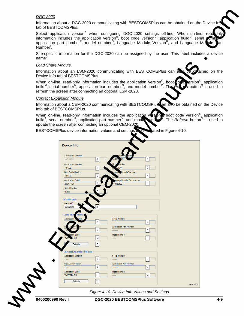
9400200990 Rev I DGC-2020 BESTCOMSPlus Software 4-9
DGC-2020 Information about a DGC-2020 communicating with BESTCOMSPlus can be obtained on the Device Info tab of BESTCOMSPlus. Select application versionA when configuring DGC-2020 settings off-line. When on-line, read-only information includes the application versionB, boot code versionC, application buildD, serial numberE, application part numberF, model numberG, Language Module VersionH, and Language Module Part NumberI. Site-specific information for the DGC-2020 can be assigned by the user. This label includes a device nameJ.
Load Share Module Information about an LSM-2020 communicating with BESTCOMSPlus can also be obtained on the Device Info tab of BESTCOMSPlus. When on-line, read-only information includes the application versionK, boot code versionL, application buildM, serial numberN, application part numberO, and model numberP. The Refresh buttonQ is used to refresh the screen after connecting an optional LSM-2020.
Contact Expansion Module Information about a CEM-2020 communicating with BESTCOMSPlus can also be obtained on the Device Info tab of BESTCOMSPlus. When on-line, read-only information includes the application versionR, boot code versionS, application buildT, serial numberU, application part numberV, and model numberW. The Refresh buttonX is used to update the screen after connecting an optional CEM-2020. BESTCOMSPlus device information values and settings are illustrated in Figure 4-10.
Figure 4-10. Device Info Values and Settings
www . El
ectric
alPar
tMan
uals
. com

4-10 DGC-2020 BESTCOMSPlus Software 9400200990 Rev I
A Application Version: When configuring DGC-2020 settings off-line, the application version for the unit to be configured must be selected. Select <1.00.07, <=1.00.07 & >1.01.00, >=1.01.00 & <1.02.00, or >=1.02.00. B Application Version: Read-only value obtained when BESTCOMSPlus is communicating with the DGC-2020. C Boot Code Version: Read-only value obtained when BESTCOMSPlus is communicating with the DGC-2020. D Application Build: Read-only value obtained when BESTCOMSPlus is communicating with the DGC-2020. E Serial Number: Read-only value obtained when BESTCOMSPlus is communicating with the DGC-2020. F Application Part Number: Read-only value obtained when BESTCOMSPlus is communicating with the DGC-2020. G Model Number: Read-only value obtained when BESTCOMSPlus is communicating with the DGC-2020. H Language Module Version: Read-only value obtained when BESTCOMSPlus is communicating with the DGC-2020. I Language Module Part Number: Read-only value obtained when BESTCOMSPlus is communicating with the DGC-2020. J Device Name: Accepts an alphanumeric character string of up to 16 characters. K Application Version: Read-only value obtained when BESTCOMSPlus is communicating with an optional LSM-2020. L Boot Code Version: Read-only value obtained when BESTCOMSPlus is communicating with an optional LSM-2020. M Application Build: Read-only value obtained when BESTCOMSPlus is communicating with an optional LSM-2020. N Serial Number: Read-only value obtained when BESTCOMSPlus is communicating with an optional LSM-2020. O Application Part Number: Read-only value obtained when BESTCOMSPlus is communicating with an optional LSM-2020. P Model Number: Read-only value obtained when BESTCOMSPlus is communicating with an optional LSM-2020. Q Refresh: Clicking this button will refresh the screen after connecting an optional LSM-2020. R Application Version: Read-only value obtained when BESTCOMSPlus is communicating with an optional CEM-2020. S Boot Code Version: Read-only value obtained when BESTCOMSPlus is communicating with an optional CEM-2020. T Application Build: Read-only value obtained when BESTCOMSPlus is communicating with an optional CEM-2020. U Serial Number: Read-only value obtained when BESTCOMSPlus is communicating with an optional CEM-2020. V Application Part Number: Read-only value obtained when BESTCOMSPlus is communicating with an optional CEM-2020. W Model Number: Read-only value obtained when BESTCOMSPlus is communicating with an optional CEM-2020. X Refresh: Clicking this button will refresh the screen after connecting an optional CEM-2020.
Device Security Setup Password protection guards against unauthorized changing of DGC-2020 settings. DGC-2020 passwords are case sensitive. Three levels of password protection are available. Each level is described in the following paragraphs. • OEM Access. This password level allows access to all settings. The default, OEM-access password
is OEM. • Settings Access. This password level allows all except uploading of firmware and clearing of device
event log. The default, settings-access password is SET. • Operator Access. The default, operator-access password is OP. This password level allows all
settings to be read and allows changes to be made to the following: o LCD Contrast
www . El
ectric
alPar
tMan
uals
. com

9400200990 Rev I DGC-2020 BESTCOMSPlus Software 4-11
o Sleep Mode o Date/Time o All Sender Fail Time Delays o Metric Conversion o Low Fuel Pre-Alarm Level o Low Fuel Alarm Level o Pre-Start Contact after Cranking o Cooldown Time o Pre-Crank Time Delay o Reset of Maintenance Interval o All controls on the Control screen available via the Metering Explorer in BESTCOMSPlus
Changing Passwords Passwords can be changed only after communication between the PC and DGC-2020 is established. Changes to passwords are made through the Device Security Setup screen. Use the Settings Explorer in BESTCOMSPlus to open the General Settings, Device Security Setup screen. The content of the Device Security Setup screen depends on the password level used when accessing the screen. For example, someone logged in with a settings-access password will be able to change only the settings-access and operator-access passwords - not the OEM-access password. Figure 4-11 illustrates Device Security Setup screen with all three of the access levels shown. A password is changed by clicking on the access levelA, entering the new passwordB, and then clicking on the Save Password buttonC.
Figure 4-11. Device Security Setup
A Access Level/Password: Read-only value obtained when BESTCOMSPlus is communicating with the DGC-2020. B Password: Accepts an alphanumeric character string of up to 16 characters. C Save Password: Clicking this button will save the password changes in BESTCOMSPlus memory.
Clock Setup Configuration of daylight saving time and coordination of the local time with universal time (if desired) is performed on this screen. If required, enter the UTC (Universal Time Coordinates) OffsetA. Choose the type of DST ConfigurationB and then set the Start DayC, End DayD, and BiasE. See Figure 4-12.
www . El
ectric
alPar
tMan
uals
. com

4-12 DGC-2020 BESTCOMSPlus Software 9400200990 Rev I
Figure 4-12. Clock Setup
A UTC Offset (min): Adjustable from -1,440 to 1,440 minutes in increments of 1. B DST Configuration: Disabled, Fixed, or Floating. C Start Day:
Fixed DST Configuration Month (January to December), Day of Month (1 to 31 in increments of 1), Hour (0 to 23 in increments of 1), Minute (0 to 59 in increments of 1).
Floating DST Configuration Month (January to December), Occurrence of Day (First to Fourth, or Last), Weekday (Sunday to Saturday), Hour (0 to 23 in increments of 1), Minute (0 to 59 in increments of 1).
D End Day: Fixed DST Configuration Month (January to December), Day of Month (1 to 31 in increments of 1), Hour (0 to 23 in increments of 1), Minute (0 to 59 in increments of 1).
Floating DST Configuration Month (January to December), Occurrence of Day (First to Fourth, or Last), Weekday (Sunday to Saturday), Hour (0 to 23 in increments of 1), Minute (0 to 59 in increments of 1).
E Bias: Hour (0 to 23 in increments of 1), Minute (0 to 59 in increments of 1).
COMMUNICATIONS DGC-2020 communication settings include setup parameters for CANBus, modem, and RS-485 communication.
CANBus Setup The DGC-2020 CANBus interface provides high-speed communication between the DGC-2020 and the engine control unit (ECU) on an electronically controlled engine. When ECU support is enabledA, the DGC-2020 will ignore the analog coolant temperature, oil pressure, and engine speed inputs and rely upon the ECU for these parameters. The DGC-2020 will also stop calculating engine run time and begin using the run time recorded by the ECU. When enabledB, the DGC-2020 will receive and retain unsolicited diagnostic trouble codes (DTCs) from an ECU with DTC capabilities. A DGC-2020 operating on a CAN network is identified by a unique address numberC. The DGC-2020 can be configured for Standard, Volvo Penta∗, or MTU MDECD. Configuring the DGC-2020 for Volvo Penta necessitates the configuration of two additional settings: Speed Select and Accelerator Position. The Speed Select settingE configures the Volvo Penta ECU to operate the engine at the primary or secondary base speed. If the engine is configured by Volvo for 60 Hz applications, the primary base speed is 1,800 rpm and the secondary base speed is 1,500 rpm. If the engine is configured by Volvo for 50 Hz applications, the primary base speed is 1,500 rpm and the secondary base speed is 1,800 rpm. The Accelerator Position settingF is expressed as a percentage and tells the Volvo Penta ECU where to set the engine speed (trim) relative to the base speed. The range of the setting is the base
www . El
ectric
alPar
tMan
uals
. com

9400200990 Rev I DGC-2020 BESTCOMSPlus Software 4-13
speed ±120 rpm. A setting of 0% will cause the engine to run at 120 rpm below the base speed, a setting of 50% will cause the engine to run at the base speed, and a setting of 100% will cause the engine to run at 120 rpm above the base speed. The Accelerator Position setting is linear with a gain of 2.4 rpm/percentage. This setting is not saved in nonvolatile memory and defaults back to 50% after DGC-2020 operating power is cycled. If the engine is configured as MTU MDEC necessitates the configuration of three additional settings: Select MDEC module type, MDEC speed demand switch, and MDEC engine RPM request. The Select MDEC module type settingG selects one of four MDEC ECU types: Module 201, Module 302, Module 303, or Module 304. The MDEC speed demand switch settingH selects one of six speed demand sources for the MDEC ECU: Analog Can, Up Down ECU, Up Down Can, Analog ECU, Frequency, or No CAN Demand. The MDEC engine RPM request settingI defines the rated rpm for the engine. In applications where the ECU is not continuously powered, the DGC-2020 has provisions for applying power to the ECU and pulsing the ECU to update its engine monitoring data. Either the DGC-2020 Fuel Solenoid or Pre-Start relay output can be used to apply power to the ECUJ. If the Pre-Start contact is selected, the Fuel Solenoid output will still close during cranking and genset operation to provide a separate indication that the genset is running. For applications where pulsing of the ECU is not desired, this pulsing featureK may be disabled. ∗The Volvo Penta ECU configuration is applicable only to the EDC3 and EMS2 models of Volvo Penta engine controllers.
ECU Limitations For some ECUs, an external source cannot stop the engine without removing power from the ECU. Turning off power to the ECU is the only way to remove fuel from the engine and shut it down. Different ECU manufacturers have their own rpm setpoints for reapplying fuel to an engine. If the ECU is powered up and the engine is still spinning above 60 rpm, then the ECU will automatically turn the fuel on. Detroit Diesel J1939 ECUs, for example, have a setpoint of 60 rpm. Not being able to stop the engine without removing ECU power causes two problems. The first problem is that the only way to stop the engine is to turn the ECU off and wait for the engine speed to decrease below 60 rpm before powering the ECU back on. Otherwise, the engine will take off running. The second problem is that while the ECU is off, you can no longer meter and update coolant level, coolant temperature alarm/pre-alarm, and crank control.
The DGC-2020 Solution The DGC-2020 resolves ECU limitations by using four timers: • Engine Shutdown.L The time in seconds to stay disconnected from the ECU when going from running
to shutdown before starting the first pulse. This timer should allow enough time for the engine to slow down so that when the DGC-2020 pulses, the ECU will not start the engine.
• Pulse Cycle Time.M The time in minutes the controller waits before pulsing. • Settling Time.N The time in tenths of seconds to gather data after connecting to the ECU during the
pulsing state. This allows all the metered values to be sent and ramp as designated by the J1939 protocol. ECU values initially sent are low and the ECU takes time to average out its own data values.
• Response Timeout.O The time in seconds to attempt communication with the ECU when the DGC-2020 is in the pulsing state or connecting state.
www . El
ectric
alPar
tMan
uals
. com

4-14 DGC-2020 BESTCOMSPlus Software 9400200990 Rev I
Figure 4-13. CANBus Setup
A Enable ECU Support: Check box to enable ECU support. B Enable DTC Support: Check box to enable DTC support. C CANBus Address: Accepts an address number from 0 to 253 in increments of 1. D ECU Config: Standard, Volvo Penta, or MTU MDEC. E Speed Select: Primary or Secondary. F Accelerator Position: Adjustable from 0 to 100% in 1% increments. G Select MDEC module type: Can Module 201, 302, 303, or 304. H MDEC speed demand switch: Analog CAN, Analog ECU, Up Down ECU, Up Down Can, Frequency, or No CAN Demand. I MDEC engine RPM request: Adjustable from 1,400 to 2,000 in increments of 1. J Output Select: Fuel Contact or Pre-start Contact. K Pulsing: Enable or Disable. L Engine Shutdown: Adjustable from 1 to 60 s in 1 s increments. M Pulse Cycle Time: Adjustable from 1 to 60 s in 1 s increments. N Settling Time: Adjustable from 5,500 to 30,000 ms in 1 ms increments. O Response Timeout: Adjustable from 1 to 60 s in 1 s increments.
Modem Setup (Optional) DGC-2020 controllers with style number xxxxxMxxx are equipped with an internal telephone modem that has dial-in and dial-out capability. The modem gives the DGC-2020 the ability to dial up to four telephone numbersA and annunciate user-selected conditions to specified pagersB. These user-selected conditions includeC: • 27-1 Trip Alarm • 27-2 Trip Alarm • 32 Trip Alarm • 40 Trip Alarm • 47 Trip Alarm • 51-1 Trip Alarm • 51-2 Trip Alarm • 59-1 Trip Alarm • 59-2 Trip Alarm • 81O Trip Alarm • 81U Trip Alarm • 27-1 Trip Pre-Alarm • 27-2 Trip Pre-Alarm www .
Elec
tricalP
artM
anua
ls . c
om

9400200990 Rev I DGC-2020 BESTCOMSPlus Software 4-15
• 32 Trip Pre-Alarm • 40 Trip Pre-Alarm • 47 Trip Pre-Alarm • 51-1 Trip Pre-Alarm • 51-2 Trip Pre-Alarm • 59-1 Trip Pre-Alarm • 59-2 Trip Pre-Alarm • 81O Trip Pre-Alarm • 81U Trip Pre-Alarm • Auto Restart Failure Alarm • Auxiliary Input x Closed (x = 1 to 16) • AVR Output Limit • Battery Charger Fail Status • Battery Overvoltage Pre-Alarm • CEM Comms Failure • Coolant Temp Sender Fail Alarm • Coolant Temp Sender Fail Pre-Alarm • Cooldown Timer Active • Duplicate CEM Pre-Alarm • Duplicate LSM Pre-Alarm • Emergency Stop Alarm • Engine Running • Fuel Leak Detect Status • Fuel Level Sender Fail Alarm • Fuel Level Sender Fail Pre-Alarm • GOV Output Limit • High Coolant Temperature Alarm • High Coolant Temp Pre-Alarm • High Fuel Pre-Alarm • ID Missing Pre-Alarm • ID Repeat Pre-Alarm • Intergenset Comms Failure • kW Overload 1 Pre-Alarm • kW Overload 2 Pre-Alarm • kW Overload 3 Pre-Alarm • Loss of ECU Coms Alarm • Loss of ECU Coms Pre-Alarm • Loss of Generator Voltage Sensing Alarm • Low Battery Voltage Pre-Alarm • Low Coolant Level Status • Low Coolant Temp Pre-Alarm • Low Fuel Alarm • Low Fuel Pre-Alarm • Low Oil Pressure Alarm • Low Oil Pressure Pre-Alarm • LSM Comms Failure • MPU Speed Sender Fail Alarm • Oil Pressure Sender Fail Alarm • Oil Pressure Sender Fail Pre-Alarm • Overcrank Alarm • Overspeed Alarm • Reserved • Scheduled Maintenance Pre-Alarm • Switch Not in Auto • Transfer Fail Alarm • Virtual Output x Status (x = 1 to 8) • Weak Battery Voltage Pre-Alarm
www . El
ectric
alPar
tMan
uals
. com

4-16 DGC-2020 BESTCOMSPlus Software 9400200990 Rev I
Dial-Out The DGC-2020 uses telelocator alphanumeric protocol (TAP) version 1.7 when communicating with paging companies. This data formatD specifies seven data bits with even parity. If required, eight data bits with no parity may be specified. The message string sent by the DGC-2020 can be limited to a length supported by the receiving pagersE. If a message to be transmitted by the DGC-2020 exceeds the pager message limit, the DGC-2020 will make multiple calls to transmit the complete message. Dial-out messages are sent by the DGC-2020 at a user-defined intervalF. This interval gives an operator the opportunity to dial into the DGC-2020. A second user-defined intervalG determines how frequently dial-out attempts are made following a dial-out failure.
Dial-In When the DGC-2020 modem shares a line used for voice communication, the number of ringsH required for the modem to answer can be increased to allow time for an operator to answer an incoming telephone call.
Figure 4-14. Modem Setup
A Dial Out Number: Accepts a telephone number of up to 16 characters. B Pager ID: Accepts a pager identification number of up to 16 characters. C Modem Dialout Conditions: Check boxes to select conditions that will initiate a dial-out message. D Pager Coms Data Format: 7 bit – Even Parity or 8 bit – No Parity. E Pager Buffer Limit: Adjustable from 80 to 200 characters in increments of 40. F Modem Offline Delay: Adjustable from 1 to 240 min in 1 min increments. G Inter Dialout Activation Delay: A delay of 15, 30, 60, or 120 s may be selected. H Rings for Modem Answer: Adjustable from 1 to 9 in increments of 1.
RS-485 Setup (Optional) DGC-2020 controllers with the optional RS-485 communication port (style number xxxRxxxxx) can be monitored and controlled via a polled network using the Modbus protocol. Adjustable RS-485 port settings include the baud rateA, parityB, and port addressC. Fixed RS-485 port settings include the number of data bits (8) and stop bits (1). Modbus register values for the DGC-2020 are listed and defined in Appendix B, Modbus Communication. BESTCOMSPlus RS-485 port settings are illustrated in Figure 4-15.
www . El
ectric
alPar
tMan
uals
. com

9400200990 Rev I DGC-2020 BESTCOMSPlus Software 4-17
Figure 4-15. RS-485 Setup
A Baud Rate: A value of 1200, 2400, 4800, or 9600 may be selected. B Parity: No Parity, Odd Parity, or Even Parity. C Modbus Address: A value of 1 to 247 may be entered in increments of 1.
SYSTEM PARAMETERS System parameters configure the DGC-2020 for operation with a specific application and are divided into three categories: system, engine cranking, and sensing transformers.
System Settings The following settings are used to configure the DGC-2020 for operation with a specific genset application.
Genset Electrical Parameters Genset electrical parameters used by the DGC-2020 include the genset connection type, power rating, and voltage rating. Genset connection typesA accommodated by the DGC-2020 include three, three-phase configurations (delta, wye, and four-wire delta) and two single-phase configurations (sensing across phases A and B or A and C). The DGC-2020 is compatible with gensets having power ratingsB up to 9,999 kW and voltage ratingsC up to 9,999 Vac. The 32 and 40Q protection functions use the Rated Power Factor settingD when determining pickup.
Engine Speed Measurement The DGC-2020 can be configured to detect engine speedE from a magnetic pickup (MPU), the genset frequency, or both the MPU and genset frequency. When engine speed is obtained from the genset frequency, the DGC-2020 uses the rated (nominal) genset frequencyF and nominal rpm ratingG when calculating engine rpm. When engine speed is obtained from an MPU, the DGC-2020 uses the nominal rpm ratingF and the number of flywheel teethH when calculating engine rpm. The speed signal from the MPU takes priority when both the genset frequency and MPU are selected as the engine speed source. If both MPU and genset frequency are selected and the MPU fails, the DGC-2020 will automatically switch to the genset frequency as the engine speed source. When the CAN interface is used, the speed signal source settings must be set at MPU or MPU_Gen. This allows the DGC-2020 to receive the engine speed data sent by the ECU via the SAE J1939 protocol.
Engine Cooldown After a genset’s load is removed, the DGC-2020 can ensure proper engine and turbocharger cooldown by maintaining engine operation for a user-specified duration. The cooldown time delayI is initiated for any one of the following conditions: • Genset load is removed and engine shutdown is permitted • Auto transfer switch (ATS) opens while operating in Auto mode • Remote shutdown is initiated
EPS Threshold Indication that the emergency power system is supplying load is determined by a user-adjustable threshold settingJ expressed as a percentage of the genset CT (nominal) primary rating.
www . El
ectric
alPar
tMan
uals
. com

4-18 DGC-2020 BESTCOMSPlus Software 9400200990 Rev I
The Low Line Scale Factor settingK is used to automatically adjust the EPS threshold settings in applications that may utilize more than one type of genset connections. The scale factor setting is implemented when the DGC-2020 senses a contact closure at a contact input programmed to activate scaling of the settings. The value of the scale factor setting serves as a multiplier for the threshold settings. For example, if a scale factor contact input is received bye the DGC-2020 and the scale factor setting is 2.000, the threshold setting will be doubled (2.000 x PU).
Measurement/Metering Units The user can configure the DGC-2020 to display and report engine oil pressure and coolant temperature in English or metric units of measureL.
Battery Voltage The nominal voltageM of the starter battery is used by the DGC-2020 to detect and annunciate battery overvoltage and low or weak battery voltage.
NFPA Compliance Level The DGC-2020 can be used in an application requiring compliance with NFPA Standard 110. Levels 1 and 2 of Standard 110 are supportedN. Selecting level 1 or 2 affects DGC-2020 operation in the following ways: • The number of crank cycles is fixed at 3 • Crank cycle time is fixed at 15 seconds • Continuous crank time is fixed at 45 seconds • The low coolant temperature pre-alarm setting is fixed at 70°F
Horn An output contact configured (through programmable logic) to energize a hornO can be enabled and disabled through BESTCOMSPlus or at the DGC-2020 front panel.
Single-Phase Override The DGC-2020 will switch to single-phase voltage sensingP when a contact input (programmed as a single-phase override input) is received. Either A-to-B or A-to-C sensing can be selected.
Fuel Level Function This settingQ allows the selection of four fuel types: Fuel Lvl, Natural Gas, Liquid Propane, or Disabled. Selecting a fuel type other than Fuel Lvl will disable any fuel level indication, alarm, and pre-alarm and disable the Fuel Level value on the Engine screen of the Metering Explorer in BESTCOMSPlus.
Load Sharing Module A J1939 AddressR must be entered when an optional LSM-2020 is enabledS.
Power Up Delay In some cases, the ECO takes longer than the DGC-2020 to power up. The power up delay settingT is used to delay the initial pulsing of the ECU for data on DGC-2020 power up.
Contact Expansion Module A J1939 AddressU must be entered when the optional CEM-2020 is enabledV. BESTCOMSPlus system settings (DGC-2020, System Parameters, System Settings) are illustrated in Figure 4-16.
www . El
ectric
alPar
tMan
uals
. com

9400200990 Rev I DGC-2020 BESTCOMSPlus Software 4-19
Figure 4-16. System Settings
A Generator Connection: Delta, Wye, 1-Phase A-B, 1-Phase A-C, or 4-Wire Delta. B Genset kW Rating: Adjustable from 5 to 9,999 kW in 1 kW increments. C Rated Volts: Adjustable from 1 to 999 Vac in 1 Vac increments. D Rated Power Factor: Adjustable from -1 to 1 in increments of 0.001. E Speed Signal Source: MPU, Gen Freq, or MPU_Gen Freq. F Rated Frequency: 50/60 or 400 Hz. G Rated Engine RPM: Adjustable from 750 to 3,600 rpm in 1 rpm increments. H Number Fly Wheel Teeth: Adjustable from 50 to 500 in increments of 1. I No Load Cool Down Time: Adjustable from 0 to 60 minutes in 1 minute increments. J EPS Current Threshold: Adjustable from 3 to 10% of the CT primary rating in 1% increments. K Low Line Scale Factor: Adjustable from 0 to 3.000 in increments of 0.001. L System Units: English or Metric. M Battery Volts: 12 or 24 Vdc. N NFPA Level: 0 disables NFPA compliance, 1 enables Level 1 NFPA compliance, 2 enables Level 2. O Horn: Enable or Disable. P Single Phase Override Sensing: Either phases A-B or phases A-C. Q Fuel Level Function: Disable, Fuel Lvl, Natural Gas, or Liquid Propane. R Load Sharing Module: Enable or Disable. S LSM J1939 Address: Adjustable from 1 to 253 in increments of 1. T Power Up Delay: Adjustable from 0 to 60 seconds in 1 second increments. U Contact Expansion Module: Enable or Disable. V CEM J1939 Address: Adjustable from 1 to 253 in increments of 1.
Crank Settings The DGC-2020 can be programmed for either cycle or continuous engine crankingA. Cycle cranking provides multiple engine starting attemptsB. Each starting attempt consists of a fixed interval of engine crankingC followed by a rest interval of the same duration. Continuous crankingD provides a single, extended engine-starting attempt. The DGC-2020 uses the engine speed signal (supplied by a magnetic pickup (MPU) or the generator frequency) and the Crank Disconnect Limit settingE to detect engine startup (and determine when engine cranking can be stopped). The Crank Disconnect Limit setting is expressed as a percentage of the nominal engine speed. If desired, cycle or continuous cranking can be delayed after initiating engine startup. During this delayF, the Pre-Start output closes to energize the engine glow plugs or pre-start lubrication pump. The Pre-Start
www . El
ectric
alPar
tMan
uals
. com

4-20 DGC-2020 BESTCOMSPlus Software 9400200990 Rev I
output can be configured to open upon the conclusion of engine cranking or remain closed as long as the engine is runningG. The Pre-Start can be configuredH during the resting state. If Preheat Before Crank is selected, the Pre-Start output will be closed for a time equal to the Pre-crank delay time prior to re-entering the cranking state. If the Pre-crank delay setting is longer than the rest interval, the Pre-Start output will be closed for the entire rest time. Under normal operation, engine rpm is used to determine crank disconnect. The Oil Pressure Crank DisconnectI provides a secondary indication that the engine is running so that the starter will be disconnected even if no engine rpm sources are functioning. When enabled, oil pressure is used as a check of whether the engine is running. If the engine oil pressure is above the thresholdJ, the starter will be disconnected from the engine. BESTCOMSPlus engine cranking settings (DGC-2020, System Parameters, Crank Settings) are illustrated in Figure 4-17.
Figure 4-17. Engine Crank Settings
A Cranking Style: Cycle or Continuous. B Number of Crank Cycles: Adjustable from 1 to 7 cycles in 1 cycle increments. Controllers configured for
NFPA compliance have a 1 to 3-cycle range. C Cycle Crank Time: Adjustable over the range of 5 to 15 seconds in 1 second increments. D Continuous Crank Time: Adjustable from 5 to 60 seconds in 1 second increments. Controllers
configured for NFPA compliance have a 1 to 45 second range. E Crank Disconnect Limit: Adjustable from 10 to 100% of nominal engine speed. F Pre-Crank Delay: Adjustable from 0 to 30 seconds in 1 second increments. G Pre-Start Contact Configuration: Open After Disconnect or Closed While Running. H Prestart Rest Configuration: Off During Rest, On During Rest, or Preheat Before Crank. I Oil Pressure Crank Disconnect Enable: Disable or Enable. J Crank Disconnect Pressure (psi): Adjustable from 3 to 150 psi in increments of 1 psi.
Automatic Restart If the DGC-2020 has shut down due to an alarm condition, the automatic restart, when enabledA, will automatically clear alarms. An attempt to restart the engine is made after a predetermined time delayB if the ATS contact input is closed. If an ATS contact is not present, the unit will remain in READY state with its alarms cleared. A restart will not be attempted if a low fuel alarm or emergency stop is present. The number of restart attemptsC is programmable. Automatic restart attempts are recorded in the event log. BESTCOMSPlus automatic restart settings (DGC-2020, System Parameters, Automatic Restart) are illustrated in Figure 4-18.
www . El
ectric
alPar
tMan
uals
. com

9400200990 Rev I DGC-2020 BESTCOMSPlus Software 4-21
Figure 4-18. Automatic Restart Settings
A Auto Restart Enable: Enable or Disable. B Auto Restart Interval: Adjustable from 0.5 to 30 minutes in 0.5 minute increments. C Auto Restart Attempts: Adjustable from 1 to 10 in increments of 1.
Exercise Timer The exercise timer is used to start the genset at a predetermined time and run for the user-defined period. The modeA defines how often the genset will run. If monthly is selected, you must select the day of the monthB to start. If weekly is selected, you must select the day of the weekC to start. Settings for Start HourD and Start MinutesE may also be defined. The Run Period HoursF and MinutesG define how long the genset will run each time. If Run with LoadH is enabled, the DGC-2020 will close its GEN breaker during the RUN time. Contact inputs and outputs can be assigned to the function. Refer to Section 5, BESTlogic+ Programmable Logic, for more information. BESTCOMSPlus exercise timer settings (DGC-2020, System Parameters, Exercise Timer) are illustrated in Figure 4-19.
Figure 4-19. Exercise Timer Settings
A Mode: Monthly, Weekly, or Daily. B Start Day Of Month: Adjustable from 1 to 31 in 1 day increments. C Start Day Of Week: Sunday, Monday, Tuesday, Wednesday, Thursday, Friday, or Saturday. D Start Hour: Adjustable from 0 to 23 in 1 hour increments. E Start Minute: Adjustable from 0 to 59 in 1 minute increments. F Run Period Hours: Adjustable from 0 to 23 in 1 hour increments. G Run Period Minutes: Adjustable from 0 to 59 in 1 minute increments. H Run with Load: Enable or Disable.
www . El
ectric
alPar
tMan
uals
. com

4-22 DGC-2020 BESTCOMSPlus Software 9400200990 Rev I
Sensing Transformers Three sets of transformer settings configure the DGC-2020 for operation with a specific system. These settings, along with the generator voltage, generator current, and bus voltage detected by the DGC-2020, enable the DGC-2020 to accurately meter system values, offer generator protection, and synchronize the generator with the bus (style number xxxxxxxAx only).
Generator PT Settings The generator PT settings establish the nominal primaryA (generator side) and secondaryB (DGC-2020 side) voltage levels at the generator voltage-sensing transformer.
Generator CT Setting The generator CT settingC establishes the nominal, primary (generator side) current level at the generator current sensing transformer. The secondary value of the generator CT is dictated by the style number of the controller. A DGC-2020 with a style number of 1xxxxxxxx uses a nominal CT secondary rating of 1 Aac. A DGC-2020 with a style number of 5xxxxxxxx uses a nominal CT secondary rating of 5 Aac.
Bus Transformer Settings Primary and secondary bus transformer ratings are used by the automatic transfer switch function, which monitors a single-phase bus input to detect mains failure. Controllers equipped with an automatic synchronizer (style number xxxxxxxAx) also use the primary and secondary bus transformer ratings. The primary settingD establishes the nominal voltage present at phases A and C of the bus. The secondary settingE establishes the nominal voltage seen at the bus voltage input of the DGC-2020. BESTCOMSPlus sensing transformer settings (DGC-2020, System Parameters, Sensing Transformers) are illustrated in Figure 4-20.
Figure 4-20. Sensing Transformers Parameters
A Gen PT Primary Volts: Adjustable from 1 to 9999 Vac in 1 Vac increments. B Gen PT Secondary Volts: Adjustable from 1 to 480 Vac in 1 Vac increments. C Gen CT Primary Amps: Adjustable from 1 to 5,000 Aac in 1 Aac increments. D Bus PT Primary Volts: Adjustable from 1 to 9999 Vac in 1 Vac increments. E Bus PT Secondary Volts: Adjustable from 1 to 480 Vac in 1 Vac increments.
PROGRAMMABLE INPUTS DGC-2020 contact inputs can be assigned to trigger various functions and, when triggered, annunciate an alarm or pre-alarm. A user-assigned label can be assigned to each input to make identification easier. The description of these settings is organized as follows: • Configurable Local Inputs • Programmable Functions • Configurable Remote Inputs
Configurable Local Inputs Each of the 16 contact inputs can be independently configured to annunciate an alarm or pre-alarmA when the input senses a contact closure. A user-adjustable time delayB can be set to delay recognition of a contact input. By default, all inputs are configured so that they do not trigger an alarm or pre-alarm.
www . El
ectric
alPar
tMan
uals
. com

9400200990 Rev I DGC-2020 BESTCOMSPlus Software 4-23
To make identifying the contact inputs easier, a user-assigned nameC can be given to each input. Contacts can be recognizedD always or while the engine is running only. BESTCOMSPlus settings for the configurable contact inputs (DGC-2020, Programmable Inputs, Configurable Local Inputs) are illustrated in Figure 4-21.
Figure 4-21. Configurable Inputs Settings
A Alarm Configuration: None, Prealarm, or Alarm. B Activation Delay: Adjustable from 0 to 300 s in 1 s increments. C Label Text: An alphanumeric character string with a maximum of 16 characters. D Contact Recognition: Always or While Engine Running Only.
Programmable Functions Any of the 16 contact inputs can be programmed to recognize any one of nine function types: • Automatic Transfer Switch (ATS)A - Disconnect from the mains and start the generator. • Grounded Delta OverrideB - Uses Grounded Delta sensing if the generator connection is set for Delta. • Battle OverrideC - The alarms programmed to shut down the unit will be overridden and ignored. • Low-Line OverrideD - The 51, 27, and 59 settings are scaled by the low-line scale factor setting. • Single-Phase OverrideE - The unit switches to single phase sensing configuration and uses the
1 Phase Override Sensing setting (A-B or A-C). (Note: Applies only when the Single-Phase Override (A-C) input is not invoked.)
• Single-Phase Override (A-C)F - The unit switches to single phase A-C sensing configuration even if the 1 Phase Override Sensing setting is set for A-B. (Note: Applies only when the Single-Phase Override input is invoked.)
• Battery Charger FailG - When the selected input is invoked, a user selectable pre-alarm or alarm is annunciated after the activation delay.
• Low Coolant LevelH - When the selected input is invoked, a user selectable pre-alarm or alarm is annunciated after the activation delay.
• Fuel Leak DetectI - When the selected input is invoked, a user selectable pre-alarm or alarm is annunciated after the activation delay.
A setting of “None” prevents a function from being triggered by a contact input. BESTCOMSPlus settings for programmable functions (DGC-2020, Programmable Inputs, Programmable Functions) are illustrated in Figure 4-22.
www . El
ectric
alPar
tMan
uals
. com

4-24 DGC-2020 BESTCOMSPlus Software 9400200990 Rev I
Figure 4-22. Programmable Functions Settings
A Auto Transfer Switch Input: Select Input (None, 1-16) and Contact Recognition (Always or While Engine Running Only). B Grounded Delta Override: Select Input (None, 1-16) and Contact Recognition (Always or While Engine Running Only). C Battle Override: Select Input (None, 1-16) and Contact Recognition (Always or While Engine Running Only). D Low Line Override: Select Input (None, 1-16) and Contact Recognition (Always or While Engine Running Only). E Single Phase Override: Select Input (None, 1-16) and Contact Recognition (Always or While Engine Running Only). F Single Phase AC Override: Select Input (None, 1-16) and Contact Recognition (Always or While Engine Running Only). G Battery Charger Fail: Select Input (None, 1-16), Alarm Configuration (None, Alarm, Prealarm), Activation Delay (s) (0 to 300 in increments of 1), and Contact Recognition (Always or While Engine Running Only). H Low Coolant Level: Select Input (None, 1-16), Alarm Configuration (None, Alarm, Prealarm), Activation Delay (s) (0 to 300 in increments of 1), and Contact Recognition (Always or While Engine Running Only). I Fuel Leak Detect: Select Input (None, 1-16), Alarm Configuration (None, Alarm, Prealarm), Activation Delay (s) (0 to 300 in increments of 1), and Contact Recognition (Always or While Engine Running Only).
Configurable Remote Inputs An optional CEM-2020 (Contact Expansion Module) provides 10 contact inputs. Each of the 10 contact inputs can be independently configured to annunciate an alarm or pre-alarmA when the input senses a contact closure. A user-adjustable time delayB can be set to delay recognition of a contact input. By default, all inputs are configured so that they do not trigger an alarm or pre-alarm. To make identifying the contact inputs easier, a user-assigned nameC can be given to each input. Contacts can be recognizedD always or only while the engine is running. BESTCOMSPlus settings for the configurable contact inputs (DGC-2020, Programmable Inputs, Configurable Remote Inputs) are illustrated in Figure 4-23.
www . El
ectric
alPar
tMan
uals
. com
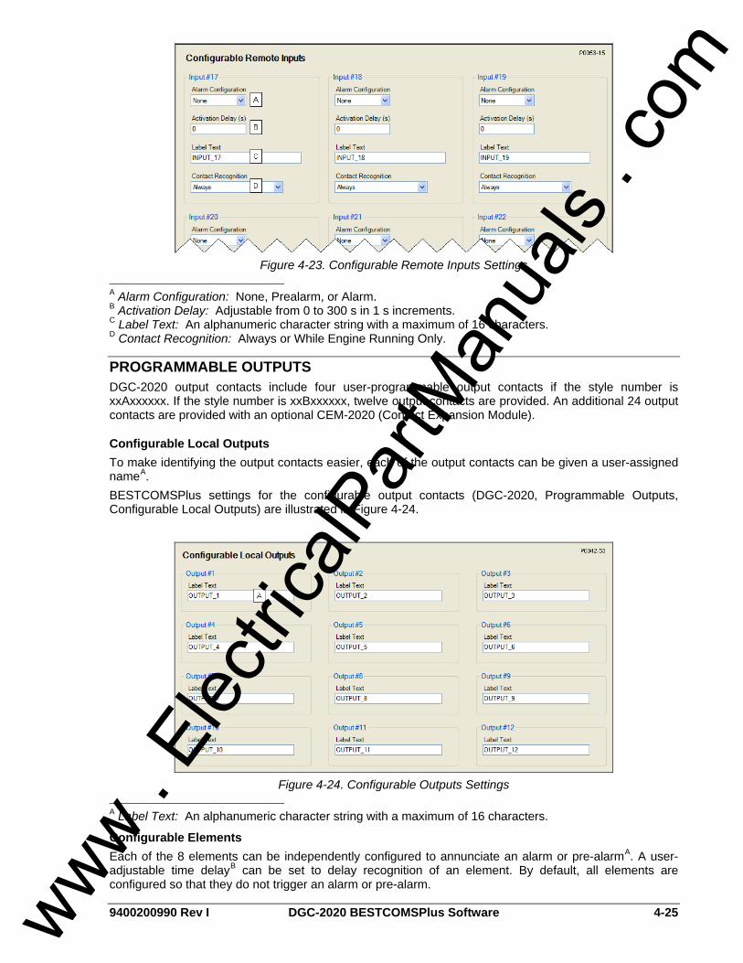
9400200990 Rev I DGC-2020 BESTCOMSPlus Software 4-25
Figure 4-23. Configurable Remote Inputs Settings
A Alarm Configuration: None, Prealarm, or Alarm. B Activation Delay: Adjustable from 0 to 300 s in 1 s increments. C Label Text: An alphanumeric character string with a maximum of 16 characters. D Contact Recognition: Always or While Engine Running Only.
PROGRAMMABLE OUTPUTS DGC-2020 output contacts include four user-programmable output contacts if the style number is xxAxxxxxx. If the style number is xxBxxxxxx, twelve output contacts are provided. An additional 24 output contacts are provided with an optional CEM-2020 (Contact Expansion Module).
Configurable Local Outputs To make identifying the output contacts easier, each of the output contacts can be given a user-assigned nameA. BESTCOMSPlus settings for the configurable output contacts (DGC-2020, Programmable Outputs, Configurable Local Outputs) are illustrated in Figure 4-24.
Figure 4-24. Configurable Outputs Settings
A Label Text: An alphanumeric character string with a maximum of 16 characters.
Configurable Elements Each of the 8 elements can be independently configured to annunciate an alarm or pre-alarmA. A user-adjustable time delayB can be set to delay recognition of an element. By default, all elements are configured so that they do not trigger an alarm or pre-alarm.
www . El
ectric
alPar
tMan
uals
. com

4-26 DGC-2020 BESTCOMSPlus Software 9400200990 Rev I
To make identifying the element easier, each of the elements can be given a user-assigned nameC. Elements can be recognizedD always or while the engine is running only. BESTCOMSPlus settings for the elements (DGC-2020, Programmable Outputs, Configurable Elements) are illustrated in Figure 4-25.
Figure 4-25. Configurable Elements Settings
A Alarm Configuration: None, Prealarm, or Alarm. B Activation Delay: Adjustable from 0 to 300 s in 1 s increments. C Label Text: An alphanumeric character string with a maximum of 16 characters. D Contact Recognition: Always or While Engine Running Only.
Configurable Remote Outputs To make identifying the output contacts easier, each of the output contacts can be given a user-assigned nameA. BESTCOMSPlus settings for the configurable output contacts (DGC-2020, Programmable Outputs, Configurable Remote Outputs) are illustrated in Figure 4-26.
Figure 4-26. Configurable Remote Outputs Settings
A Label Text: An alphanumeric character string with a maximum of 16 characters.
www . El
ectric
alPar
tMan
uals
. com

9400200990 Rev I DGC-2020 BESTCOMSPlus Software 4-27
ALARM CONFIGURATION DGC-2020 alarms and pre-alarms can be used to annunciate system, genset, and engine sender conditions. The description of the alarm configuration settings is organized as follows: • Pre-Alarms • Alarms • Sender Failure
Pre-Alarms A pre-alarm is annunciated when a condition programmed to trigger a pre-alarm is met. When a pre-alarm condition exists, it is annunciated (flashed) on the LCD, the front panel Alarm indicator flashes on and off and the Horn output (if programmed and enabled) alternates between an energized and de-energized state. The audible alarm is reset by pressing the front panel Alarm Silence pushbutton. When a pre-alarm condition ceases to exist for pre-alarms other than weak battery, all displayed annunciations are reset automatically. A weak battery pre-alarm condition is reset through the front panel by navigating to the Alarms-Status, Pre-Alarms screen, scrolling through the list of pre-alarms until “Weak Battery” is displayed, and pressing the Reset key. Active pre-alarms are displayed on the main display of the LCD. The LCD annunciates an active pre-alarm by alternating the pre-alarm message with the normally displayed data. All pre-alarms are individually displayed, in sequence, by scrolling through the LCD pre-alarms list. Each DGC-2020 pre-alarm is described in the following paragraphs. Pre-alarms may be enabled and adjusted in BESTCOMSPlus or through the front panel HMI. BESTCOMSPlus pre-alarm settings (DGC-2020, Alarm Configuration, Pre-Alarms) are illustrated in Figure 4-27.
High Fuel Level High fuel level pre-alarm settingsA consist of an enable/disable setting, a threshold setting, and an activation delay. If enabled, a high fuel level pre-alarm occurs when the metered fuel level increases above the threshold setting.
Low Battery Voltage Low battery voltage pre-alarm settingsB consist of an enable/disable setting, a threshold setting, and an activation delay. If enabled, a low battery voltage pre-alarm occurs when the battery voltage decreases below the threshold setting for the duration of the activation time delay. The threshold setting range is based on the nominal battery voltage setting on the BESTCOMSPlus System Settings tab (DGC-2020, System Parameters, System Settings).
Weak Battery Voltage Weak battery voltage pre-alarm settingsC consist of an enable/disable setting, a threshold setting, and an activation time delay. If enabled, a weak battery voltage pre-alarm latches during engine cranking when the battery voltage decreases below the threshold setting for the duration of the activation delay. The threshold setting range is based on the nominal battery voltage setting on the BESTCOMSPlus System Settings tab (DGC-2020, System Parameters, System Settings). A weak battery pre-alarm condition is reset through the front panel by navigating to the Alarms-Status, Pre-Alarms screen, scrolling through the list of pre-alarms until “Weak Battery” is displayed, and pressing the Reset key.
Battery Overvoltage Battery overvoltage pre-alarm settingsD consist of an enable/disable setting and a fixed threshold setting. If enabled, a battery overvoltage pre-alarm occurs when the battery voltage increases above the threshold setting.
Maintenance Interval Maintenance interval pre-alarm settingsE consist of an enable/disable setting and a threshold setting. If enabled, a maintenance interval pre-alarm is annunciated when the DGC-2020 maintenance timer counts down to zero from the threshold time setting.
www . El
ectric
alPar
tMan
uals
. com
4-28 DGC-2020 BESTCOMSPlus Software 9400200990 Rev I
Engine KW Overload By comparing the genset power output with the rated genset output, the level of engine loading can be determined. Three engine overload pre-alarms are available that monitor three-phase real power when three-phase sensing is active or single-phase real power if single phase sensing is active. SettingsF for each pre-alarm consist of an enable/disable setting, three-phase threshold setting, three-phase hysteresis setting, single-phase threshold setting, single phase hysteresis setting, and low line scale factor setting. If enabled, an engine overload pre-alarm occurs when the metered power level exceeds the threshold setting. The threshold setting is expressed as a percentage of the genset kW rating on the BESTCOMSPlus System Settings tab (DGC-2020, System Parameters, System Settings). The hysteresis setting functions as a pre-alarm dropout by preventing rapid switching of the alarm annunciation.
Low Fuel Level Low fuel level pre-alarm settingsG consist of an enable/disable setting and a threshold setting. If enabled, a low fuel level pre-alarm occurs when the metered fuel level decreases below the threshold setting.
High Coolant Temp High coolant temperature pre-alarm settingsH consist of an enable/disable setting and a threshold setting. If enabled, a high coolant temperature pre-alarm is annunciated when the engine coolant temperature exceeds the threshold setting for a fixed duration of 60 seconds.
Low Coolant Temp Low coolant temperature pre-alarm settingsI consist of an enable/disable setting and a threshold setting. If enabled, a low coolant temperature pre-alarm occurs when the engine coolant temperature decreases below the threshold setting.
Low Coolant Level Low coolant level pre-alarm settingsJ consist of an enable/disable setting and a threshold setting. If enabled, a low coolant level pre-alarm occurs when the metered coolant level decreases below the threshold setting.
Low Oil Pressure Low oil pressure pre-alarm settingsK consist of an enable/disable setting and a threshold setting. If enabled, a low oil pressure pre-alarm is annunciated when the engine oil pressure decreases below the threshold setting for a fixed duration of 10 seconds.
ECU Coms Fail ECU communication failure pre-alarm settingsL consist of a single enable/disable setting. If enabled, an ECU communication failure pre-alarm is annunciated when the DGC-2020 detects a communication problem in the J1939 interface linking the DGC-2020 with the ECU (engine control unit).
Active DTC Active DTC (diagnostic trouble code) pre-alarm settingsM consist of a single enable/disable setting. If CAN and DTC support are both enabled, an “active DTC” pre-alarm may be enabled to announce the presence of a condition that is causing a DTC to be sent from the ECU to the DGC-2020.
AVR Bias Output Limit AVR bias output limit settingsN consist of an enable/disable setting and an activation delay setting. If enabled, an AVR bias output limit pre-alarm is annunciated when the AVR bias output limit has been met and the activation delay has expired. This setting only applies when using the optional LSM-2020.
GOV Bias Output Limit GOV bias output limit settingsO consist of an enable/disable setting and an activation delay setting. If enabled, a GOV bias output limit pre-alarm is annunciated when the GOV bias output limit has been met and the activation delay has expired. This setting only applies when using the optional LSM-2020.
Intergenset Comm Failure Intergenset communication failure pre-alarm settingsP consist of a single enable/disable setting. If enabled, an Intergenset communication failure pre-alarm is annunciated when an individual generator detects that it had been connected to a generator network, but has lost the connection. This setting only applies when using an optional LSM-2020.
www . El
ectric
alPar
tMan
uals
. com

9400200990 Rev I DGC-2020 BESTCOMSPlus Software 4-29
LSM Comm Failure LSM-2020 communication failure pre-alarm settingsQ consist of a single enable/disable setting. If enabled, an LSM-2020 communication failure pre-alarm is annunciated when communication between an optional LSM-2020 and DGC-2020 is lost.
ID Missing ID missing pre-alarm settings consist of a single enable/disable settingR. If enabled, an ID missing pre-alarm is annunciated when an expected sequence ID of an optional LSM-2020 is not detected on the network.
ID Repeat ID repeat pre-alarm settings consist of a single enable/disable settingS. If enabled, an ID repeat pre-alarm is annunciated when two or more optional LSM-2020’s report the same expected sequence ID.
CEM Comm Failure CEM-2020 communication failure pre-alarm settingsT consist of a single enable/disable setting. If enabled, a CEM-2020 communication failure pre-alarm is annunciated when communication between an optional CEM-2020 and DGC-2020 is lost.
www . El
ectric
alPar
tMan
uals
. com

4-30 DGC-2020 BESTCOMSPlus Software 9400200990 Rev I
Figure 4-27. Pre-Alarms Configuration
A High Fuel Level: Enable or Disable, threshold is adjustable from 0 to 100% in 1 % increments. B Low Battery Voltage: Enable or Disable, threshold is adjustable from 6 to 12 Vdc (12 Vdc battery) or 12 to 24 Vdc (24 Vdc battery) in 1 Vdc increments. Activation delay is adjustable from 1 to 10 s in 1 s increments. C Weak Battery Voltage: Enable or Disable, threshold is adjustable from 4 to 8 Vdc (12 Vdc battery) or 8 to 16 Vdc (24 Vdc battery). Activation time delay is adjustable from 1 to 10 s in 1 s increments. D Battery Overvoltage: Enable or Disable, threshold is adjustable from 12 to 32 Vdc in 0.1 increments. E Maintenance Interval: Enable or Disable, threshold is adjustable from 0 to 5,000 h in 1 h increments. F Engine kW Overload: Enable or Disable, threshold is adjustable from 95 to 140% of Genset kW Rating in 1% increments. G Low Fuel Level: Enable or Disable, threshold is adjustable from 10 to 100% in 1 % increments.
www . El
ectric
alPar
tMan
uals
. com

9400200990 Rev I DGC-2020 BESTCOMSPlus Software 4-31
H High Coolant Temp: Enable or Disable, threshold is adjustable from 100 to 280°F or 38 to 138°C in 1° increments. Activation time delay is fixed at 60 s. I Low Coolant Temp: Enable or Disable, threshold is adjustable from 35 to 150°F or 2 to 65°C in 1° increments. J Low Coolant Level: Enable or Disable, threshold is adjustable from 1 to 99% in 1 % increments. K Low Oil Pressure: Enable or Disable, threshold is adjustable from 3 to 150 psi or 21 to 1,034 kPa in 7 psi or kPa increments. Activation time delay is fixed at 10 s. L ECU Coms Fail: Enable or Disable. M Active DTC: Enable or Disable. N AVR Bias Output Limit: Enable or Disable, activation delay is adjustable from 1 to 15 seconds in 1 second increments. O GOV Bias Output Limit: Enable or Disable, activation delay is adjustable from 1 to 15 seconds in 1 second increments. P Intergenset Comm Failure: Enable or Disable. Q LSM Comm Failure: Enable or Disable. R ID Missing: Enable or Disable. S ID Repeat: Enable or Disable. T CEM Comm Failure: Enable or Disable.
Alarms An alarm is annunciated when a condition programmed to trigger an alarm is detected. When an alarm condition exists, the front panel Alarm indicator lights, the Horn output (if programmed and enabled) energizes, and the cause of the alarm is displayed on the front panel LCD. An alarm condition stops the engine by opening the Fuel output contact. Alarms are reset when the DGC-2020 is set to Off mode. Each DGC-2020 alarm is described in the following paragraphs. Alarms may be enabled and adjusted in BESTCOMSPlus or through the front panel HMI. BESTCOMSPlus alarm settings (DGC-2020, Alarm Configuration, Alarms) are illustrated in Figure 4-28.
High Coolant Temperature High coolant temperature alarm settingsA consist of an enable/disable setting and a threshold setting. If enabled, a high coolant temperature alarm is triggered instantaneously when the engine coolant temperature exceeds the threshold setting. The high coolant temperature alarm has an arming delay that disables the alarm for 60 seconds after engine startup.
Low Oil Pressure Low oil pressure alarm settingsB include an enable/disable setting, an arming time delay, and a threshold setting. If enabled, a low oil pressure alarm is triggered instantaneously when the engine oil pressure decreases below the threshold setting. The arming time delay disables the low oil pressure alarm function for a user-adjustable time during engine startup.
Overspeed Overspeed alarm settingsC include an enable/disable setting, an activation delay, and a threshold setting. If enabled, an overspeed alarm occurs when the engine speed (in rpm) exceeds the threshold setting for the duration of the activation time delay.
Low Fuel Level Low fuel level alarm settingsD consist of an enable/disable setting, an activation delay setting, and a threshold setting. If enabled, a low fuel level alarm is triggered when the metered fuel level drops below the threshold setting for the duration of the activation time delay.
Low Coolant Level Low coolant level alarm settingsE consist of an enable/disable setting and a threshold setting. If enabled, a low coolant level alarm is triggered when the metered coolant drops below the threshold setting.
www . El
ectric
alPar
tMan
uals
. com

4-32 DGC-2020 BESTCOMSPlus Software 9400200990 Rev I
Figure 4-28. Alarms Configuration
A High Coolant Temp: Enable or Disable, threshold is adjustable from 100 to 280°F or 38 to 138°C in 1° increments. Arming time delay is fixed at 60 s. B Low Oil Pressure: Enable or Disable, threshold is adjustable from 3 to 150 psi or 21 to 1,034 kPa in 7 psi or 1 kPa increments. Arming time delay is adjustable from 5 to 15 s in 1 s increments. C Overspeed: Enable or Disable, threshold is adjustable from 105 to 140% of the rated engine rpm. Activation time delay is adjustable from 0 to 500 s in 1 s increments. D Low Fuel Level: Enable or Disable, threshold is adjustable from 0 to 100% in 1% increments. Activation time delay is adjustable from 0 to 30 in 1 s increments. E Low Coolant Level: Enable or Disable, threshold is adjustable from 1 to 99% in 1% increments.
Sender Fail The DGC-2020 can be configured to annunciate a pre-alarm or alarm when a loss of signal is detected at the coolant temperatureA, oil pressureB, or fuel level senderC input. A loss of generator sensing voltageD (when the DGC-2020 is operating in Run or Auto mode with the ATS closed) can also be configured to trigger a pre-alarm or alarm. The speed sender failE alarm is always enabled. A user-adjustable time delay is provided for each sender/sensing alarm/pre-alarm. Alarm and pre-alarm annunciations for loss of engine speed signals is not user-programmable and operates as follows. If the MPU (magnetic pickup) or generator frequency is programmed as the sole engine speed source and that signal source fails, an alarm (and shutdown) is triggered. If the engine speed source is configured as MPU and generator frequency and a loss of one of the signal sources occurs, a pre-alarm is annunciated. An alarm (and shutdown) is triggered if both speed signals are lost. BESTCOMSPlus settings for the sender fail functions (DGC-2020, Alarm Configuration, Sender Fail) are illustrated in Figure 4-29.
www . El
ectric
alPar
tMan
uals
. com
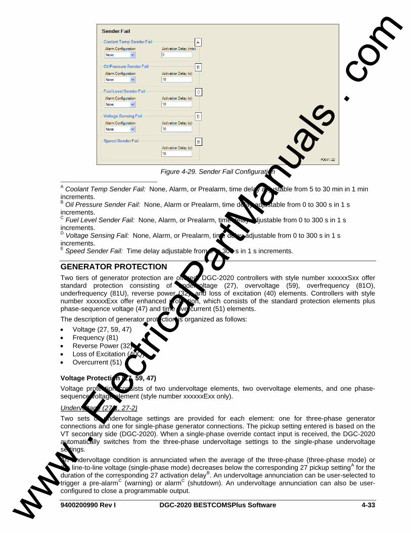
9400200990 Rev I DGC-2020 BESTCOMSPlus Software 4-33
Figure 4-29. Sender Fail Configuration
A Coolant Temp Sender Fail: None, Alarm, or Prealarm, time delay adjustable from 5 to 30 min in 1 min increments. B Oil Pressure Sender Fail: None, Alarm or Prealarm, time delay adjustable from 0 to 300 s in 1 s increments. C Fuel Level Sender Fail: None, Alarm, or Prealarm, time delay adjustable from 0 to 300 s in 1 s increments. D Voltage Sensing Fail: None, Alarm, or Prealarm, time delay adjustable from 0 to 300 s in 1 s increments. E Speed Sender Fail: Time delay adjustable from 0 to 300 s in 1 s increments.
GENERATOR PROTECTION Two tiers of generator protection are offered. DGC-2020 controllers with style number xxxxxxSxx offer standard protection consisting of undervoltage (27), overvoltage (59), overfrequency (81O), underfrequency (81U), reverse power (32), and loss of excitation (40) elements. Controllers with style number xxxxxxExx offer enhanced protection, which consists of the standard protection elements plus phase-sequence voltage (47) and time overcurrent (51) elements. The description of generator protection is organized as follows: • Voltage (27, 59, 47) • Frequency (81) • Reverse Power (32) • Loss of Excitation (40Q) • Overcurrent (51)
Voltage Protection (27, 59, 47) Voltage protection consists of two undervoltage elements, two overvoltage elements, and one phase-sequence voltage element (style number xxxxxxExx only).
Undervoltage (27-1, 27-2) Two sets of undervoltage settings are provided for each element: one for three-phase generator connections and one for single-phase generator connections. The pickup setting entered is based on the VT secondary side (DGC-2020). When a single-phase override contact input is received, the DGC-2020 automatically switches from the three-phase undervoltage settings to the single-phase undervoltage settings. An undervoltage condition is annunciated when the average of the three-phase (three-phase mode) or the line-to-line voltage (single-phase mode) decreases below the corresponding 27 pickup settingA for the duration of the corresponding 27 activation delayB. An undervoltage annunciation can be user-selected to trigger a pre-alarmC (warning) or alarmC (shutdown). An undervoltage annunciation can also be user-configured to close a programmable output.
www . El
ectric
alPar
tMan
uals
. com

4-34 DGC-2020 BESTCOMSPlus Software 9400200990 Rev I
The hysteresis settingD functions as an undervoltage dropout by preventing rapid switching of the pickup output. A frequency-based inhibit settingE prevents a 27 trip from occurring during an undervoltage condition associated with system startup. A low-line scale factor settingF is used to automatically adjust the undervoltage pickup settings in applications that may utilize more than one type of genset connections. The scale factor setting is implemented when the DGC-2020 senses a contact closure at a contact input programmed to activate scaling of the protection settings. The value of the scale factor setting serves as a multiplier for the pickup settings. For example, if a scale factor contact input is received by the DGC-2020 and the scale factor setting is 2.000, the pickup setting will be doubled (2.000 × PU). BESTCOMSPlus voltage protection settings (DGC-2020, Generator Protection, Voltage, Undervoltage) are illustrated in Figure 4-30. The 27-1 element is shown.
Figure 4-30. Undervoltage Protection Settings
A Pickup: Adjustable from 70 to 576 Vac in 1 Vac increments. B Activation Delay: Adjustable from 0 to 30 s in 0.1 s increments. C Alarm Configuration: None, Alarm, or Prealarm. D Hysteresis: Adjustable from 1 to 60 Vac in 1 Vac increments. E Inhibit Frequency: Adjustable from 20 to 400 Hz in 1 Hz increments. F Low Line Scale Factor: Adjustable from 0 to 3.000 in increments of 0.001. Overvoltage (59-1, 59-2) Two sets of overvoltage settings are provided for each element: one for three-phase generator connections and one for single-phase generator connections. The pickup setting entered is based on the VT secondary side (DGC-2020). When a single-phase override contact input is received, the DGC-2020 automatically switches from the three-phase overvoltage settings to the single-phase overvoltage settings. An overvoltage condition is annunciated when the average of the three-phase (three-phase mode) or the line-to-line voltage (single-phase mode) increases above the corresponding 59 pickup settingA for the duration of the corresponding 59 activation delayB. An overvoltage annunciation can be user-selected to trigger a pre-alarmC (warning) or alarmC (shutdown). An overvoltage annunciation can also be user-configured to close a programmable output. The hysteresis settingD functions as an undervoltage dropout by preventing rapid switching of the pickup output. A low-line scale factor settingE is used to automatically adjust the overvoltage pickup settings in applications that may utilize more than one type of genset connections. The scale factor setting is implemented when the DGC-2020 senses a contact closure at a contact input programmed to activate scaling of the protection settings. The value of the scale factor setting serves as a multiplier for the pickup settings. For example, if a scale factor contact input is received by the DGC-2020 and the scale factor setting is 2.000, the pickup setting will be doubled (2.000 × PU).
www . El
ectric
alPar
tMan
uals
. com

9400200990 Rev I DGC-2020 BESTCOMSPlus Software 4-35
BESTCOMSPlus voltage protection settings (DGC-2020, Generator Protection, Voltage, Overvoltage) are illustrated in Figure 4-32. The 59-1 element is shown.
Figure 4-31. Overvoltage Protection Settings
A Pickup: Adjustable from 70 to 576 Vac in 1 Vac increments. B Activation Delay: Adjustable from 0 to 30 s in 0.1 s increments. C Alarm Configuration: None, Alarm, or Prealarm. D Hysteresis: Adjustable from 1 to 60 Vac in 1 Vac increments. E Low Line Scale Factor: Adjustable from 0 to 3.000 in increments of 0.001. Phase Imbalance (47) DGC-2020 controllers with enhanced generator protection (style number xxxxxxExx) are capable of protecting against voltage imbalances between any of the three phases. The pickup setting entered is based on the VT secondary side (DGC-2020). A phase imbalance condition is annunciated when the difference between any of the three phases of generator voltage increases above the 47 pickup settingA for the duration of the 47 activation delay settingB. A phase imbalance annunciation can be user-selected to trigger a pre-alarmC (warning) or alarmC (shutdown). A phase imbalance annunciation can also be user-configured to close a programmable output. The hysteresis settingD functions as a phase imbalance dropout by preventing rapid switching of the pickup output. BESTCOMSPlus voltage protection settings (DGC-2020, Generator Protection, Voltage, Phase Imbalance) are illustrated in Figure 4-32.
Figure 4-32. Phase Imbalance Protection Settings
A Pickup: Adjustable from 5 to 100 Vac in 1 Vac increments. B Activation Delay: Adjustable from 0 to 30 s in 0.1 s increments. C Alarm Configuration: None, Alarm, or Prealarm. D Hysteresis: Adjustable from 1 to 5 Vac in 1 Vac increments.
www . El
ectric
alPar
tMan
uals
. com

4-36 DGC-2020 BESTCOMSPlus Software 9400200990 Rev I
Frequency Protection (81O/U) Two sets of frequency protection settings are provided: one for underfrequency (81U) and one for overfrequency (81O).
Underfrequency (81U) An underfrequency condition is annunciated when the generator frequency decreases below the 81U pickup settingA for the duration of the 81U activation delay settingB. An underfrequency annunciation can be user-selected to trigger a pre-alarmC (warning) or alarmC (shutdown). An underfrequency annunciation can also be user-configured to close a programmable output. A voltage-based inhibit settingD prevents an 81U trip from occurring during an underfrequency condition associated with system startup. The hysteresis settingE functions as an underfrequency dropout by preventing rapid switching of the pickup output.
Overfrequency (81O) When the generator frequency increases above the 81O pickup settingF for the duration of the 81O activation delay settingG, an overfrequency condition is annunciated. An overfrequency annunciation can be user-selected to trigger a pre-alarmH (warning) or alarmH (shutdown). An overfrequency condition can also be user configured to close a programmable output. The hysteresis settingI functions as an overfrequency dropout by preventing rapid switching of the pickup output. BESTCOMSPlus frequency protection settings (DGC-2020, Generator Protection, Frequency) are illustrated in Figure 4-33.
Figure 4-33. Frequency Protection Settings
A Underfrequency Pickup: Adjustable from 45 to 66 Hz in 0.1 Hz increments for 50/60 Hz controllers (style number x1xxxxxxxx). Adjustable from 360 to 440 Hz in 0.1 Hz increments for 400 Hz controllers (style number x2xxxxxxxx). B Underfrequency Activation Delay: Adjustable from 0 to 30 s in 0.1 s increments. C Underfrequency Alarm Configuration: None, Alarm, or Prealarm. D Underfrequency Inhibit Volts: Adjustable from 70 to 576 Vac in 1 Vac increments. E Hysteresis: Adjustable from 0.1 to 40 Hz in 0.1 Hz increments. F Overfrequency Pickup: Adjustable from 45 to 65 Hz in 0.1 Hz increments for 50/60 Hz controllers (style number x1xxxxxxxx). Adjustable from 360 to 440 Hz in 0.1 Hz increments for 400 Hz controllers (style number x2xxxxxxxx). G Overfrequency Activation Delay: Adjustable from 0 to 30 s in 0.1 s increments. H Overfrequency Alarm Configuration: None, Alarm, or Prealarm. I Hysteresis: Adjustable from 0.1 to 40 Hz in 0.1 Hz increments.
Reverse Power Protection (32) Two sets of reverse power settings are provided: one for three-phase generator connections and one for single-phase generator connections. The pickup setting entered is based on the CT secondary side (DGC-2020). When a single-phase override contact input is received by the DGC-2020, the reverse
www . El
ectric
alPar
tMan
uals
. com

9400200990 Rev I DGC-2020 BESTCOMSPlus Software 4-37
power protection settings automatically switch from the three-phase settings to the single-phase reverse power protection settings. The 32 element monitors three-phase real power when three-phase sensing is active or single-phase real power if single-phase sensing is active. When the total wattage in the tripping direction (generator absorbing power) is greater than the pickup settingA for the duration of the 32 activation delay settingB, a reverse power condition is annunciated. A reverse power annunciation can be user-selected to trigger a pre-alarmC (warning) or alarmC (shutdown). A reverse power annunciation can also be user-configured to close a programmable output. The hysteresis settingD functions as a reverse power dropout by preventing rapid switching of the pickup output. BESTCOMSPlus reverse power protection settings (DGC-2020, Generator Protection, Reverse Power) are illustrated in Figure 4-34.
Figure 4-34. Reverse Power Protection Settings
A Pickup: -50% to 5% of rated watts in 0.1% increments. B Activation Delay: Adjustable from 0 to 30 s in 0.1 s increments. C Alarm Configuration: None, Alarm, or Prealarm. D Hysteresis: Adjustable from 1% to 10% in 0.1% increments.
Loss of Excitation Protection (40Q) Two sets of loss of excitation settings are provided: one for three-phase generator connections and one for single-phase generator connections. The pickup settingA entered is based on the CT secondary side (DGC-2020). When a single-phase override contact input is received by the DGC-2020, the loss of excitation protection settings automatically switch from the three-phase settings to the single-phase loss of excitation protection settings. When a generator’s excitation power is lost, the generator acts as a large inductor. The generator begins to absorb large quantities of vars. The 40Q acts on the principal that if a generator begins to absorb vars outside of its steady state capability curve, it has likely lost its normal excitation supply. The 40Q monitors three-phase reactive power when three-phase sensing is active or single-phase reactive power if single-phase sensing is active. It compares the reactive power to the 40Q response curve defined by the 40Q pickup setting. Refer to Figure 4-35.
www . El
ectric
alPar
tMan
uals
. com
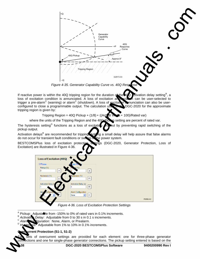
4-38 DGC-2020 BESTCOMSPlus Software 9400200990 Rev I
Figure 4-35. Generator Capability Curve vs. 40Q Response
If reactive power is within the 40Q tripping region for the duration of the 40Q activation delay settingB, a loss of excitation condition is annunciated. A loss of excitation annunciation can be user-selected to trigger a pre-alarmC (warning) or alarmC (shutdown). A loss of excitation annunciation can also be user-configured to close a programmable output. The calculation used in the DGC-2020 for the approximate tripping region is given by:
Tripping Region = 40Q Pickup + (1/8) ∗ ((Actual Watts ∗ 100)/Rated var) where the units of the Tripping Region and the 40Q Pickup setting are percent of rated var. The hysteresis settingD functions as a loss of excitation dropout by preventing rapid switching of the pickup output. Activation delaysB are recommended for tripping. Adding a small delay will help assure that false alarms do not occur for transient fault conditions or swings in the power system. BESTCOMSPlus loss of excitation protection settings (DGC-2020, Generator Protection, Loss of Excitation) are illustrated in Figure 4-36.
Figure 4-36. Loss of Excitation Protection Settings
A Pickup: Adjustable from -150% to 0% of rated vars in 0.1% increments. B Activation Delay: Adjustable from 0 to 30 s in 0.1 s increments. C Alarm Configuration: None, Alarm, or Prealarm. D Hysteresis: Adjustable from 1% to 10% in 0.1% increments.
Overcurrent Protection (51-1, 51-2) Two sets of overcurrent settings are provided for each element: one for three-phase generator connections and one for single-phase generator connections. The pickup setting entered is based on the
www . El
ectric
alPar
tMan
uals
. com

9400200990 Rev I DGC-2020 BESTCOMSPlus Software 4-39
CT secondary side (DGC-2020). When a single-phase override contact input is received by the DGC-2020, the overcurrent protection settings automatically switch from the three-phase settings to the single-phase overcurrent protection settings. When any of the phase currents increase above the pickup settingA for the duration of the overcurrent time delay, an overcurrent condition is annunciated. An overcurrent annunciation can be user-selected to trigger a pre-alarmB (warning) or alarmB (shutdown). An overcurrent annunciation can also be user-configured to close a programmable output. The overcurrent time delay is controlled by a time dial settingC and a curve settingD. The curve setting can be set at F (fixed) or one of 16 inverse time characteristic curves can be selected. When the fixed curve setting is selected, the time dial setting determines the overcurrent time delay with no regard to the generator current level. When one of the inverse time characteristic curves is selected, the time dial setting, along with the level of measured generator current, determines the overcurrent time delay. As overcurrent protection settings are entered in BESTCOMSPlus, a plotE of the settings is automatically created to illustrate the overcurrent pickup curve. The available time characteristic curves are listed below and illustrated in Appendix A, Time Overcurrent Characteristic Curves. • A, standard inverse • I2, inverse • A, standard inverse • I2, inverse • B, very inverse • L1, long inverse • C, extremely inverse • L2, long inverse • D, definite • M, moderately inverse • E1, extremely inverse • S1, short inverse • E2, extremely inverse • S2, short inverse • G, long inverse • V1, very inverse • I1, inverse • V2, very inverse A low-line scale factor settingF is used to automatically adjust the overcurrent pickup settings in applications that may utilize more than one type of genset connections. The scale factor setting is implemented when the DGC-2020 senses a contact closure at a contact input programmed to activate scaling of the protection settings. The value of the scale factor setting serves as a multiplier for the pickup settings. For example, if a scale factor contact input is received by the DGC-2020 and the scale factor setting is 2.000, the pickup setting will be doubled (2.000 × PU). The graph can be setG to display the 1 Phase or 3 Phase curve as determined by the settings on the left side of the chart. BESTCOMSPlus overcurrent protection settings (DGC-2020, Generator Protection, Overcurrent) are illustrated in Figure 4-37. The 51-1 element is shown.
www . El
ectric
alPar
tMan
uals
. com

4-40 DGC-2020 BESTCOMSPlus Software 9400200990 Rev I
Figure 4-37. Overcurrent Protection Settings
A Pickup: Adjustable from 0.9 to 7.75 Aac for 5 Aac current sensing (style number 5xxxxxxxx) or 0.18 to 1.18 Aac for 1 Aac current sensing (style number 1xxxxxxxx). B Alarm Configuration: None, Alarm, or Prealarm C Time Dial: Adjustable from 0 to 30 s for F (fixed) curve, 0 to 9.9 for all other curve selections. D Curve: A, B, C, D, E1, E2, F, G, I1, I2, L1, L2, M, S1, S2, V1, or V2. E Overcurrent Pickup Curve. F Low Line Scale Factor: Adjustable from 0 to 3.000 in 0.001 increments. G Display: 1 Phase or 3 Phase.
BREAKER MANAGEMENT DGC-2020 breaker management features include the control of two, continuous- or pulse-controlled breakers, load transfer upon detection of a mains failure, two modes of automatic genset synchronization, and settings for stable or dead bus detection. Open transitions are implemented in load transfers to and from the mains. The description of breaker management is organized as follows: • Breaker Hardware • Bus Condition Detection • Synchronizer
Breaker Hardware By default, one (generator) breaker is enabledA for control and monitoring by the DGC-2020. In applications requiring control of a generator breaker and mains breaker, a second (mains) breaker can be enabledB and configured. When two breakers are configured (enabled), the DGC-2020 can be enabled to automatically transfer load power from the mains to the genset during a mains failureC. This feature also enables the DGC-2020 to transfer the load back to the mains once mains power is restored. Settings include a transfer delayD, return delayE, and max transfer timeF. Breakers controlled by pulse or continuous inputs are supportedG. Separate settings for each breaker’s openH and closeI pulse widths are provided. During synchronization of the generator with the bus (Anticipatory mode only), the DGC-2020 uses the breaker closing timeJ to calculate the optimum time to close the breaker.
www . El
ectric
alPar
tMan
uals
. com

9400200990 Rev I DGC-2020 BESTCOMSPlus Software 4-41
When a close command is issued, the DGC-2020 monitors the breaker status and annunciates a breaker failure if the breaker does not close within the time defined by the breaker-close wait-time delayK. Typically, this parameter is set to be longer than twice the breaker closing time. The dead bus close enable settingL enables a machine to close its breaker onto a dead bus. This can be used to make sure only one machine can close onto a dead bus at a time, if desired, preventing multiple machines closing to the dead bus at the same time, potentially out of phase with each other. When this setting is disabled, a machine can only close onto a stable bus. BESTCOMSPlus breaker hardware settings (DGC-2020, Breaker Management, Breaker Hardware) are illustrated in Figure 4-38.
Figure 4-38. Breaker Hardware Settings
A Generator Breaker: Configured, NOT Configured. B Mains Breaker: Configured or NOT Configured. C Mains Fail Transfer: Enable or Disable. This setting does not apply when generator frequency is
400Hz. D Mains Fail Transfer Delay: Adjustable from 1 to 300 s in 1 s increments. E Mains Fail Return Delay: Adjustable from 0 to 1,800 s in 1 s increments. F Mains Fail Max Transfer Time: Adjustable from 10 to 120 s in 1 s increments. G Contact Type: Continuous or Pulse. H Open Pulse Time: Adjustable from 0.01 to 0.80 s in 0.01 s increments. I Close Pulse Time: Adjustable from 0.01 to 0.80 s in 0.01 s increments. J Breaker Closing Time: Adjustable from 0 to 800 ms in 5 ms increments.
www . El
ectric
alPar
tMan
uals
. com

4-42 DGC-2020 BESTCOMSPlus Software 9400200990 Rev I
K Breaker Close Wait Time: Adjustable from 0.1 to 600 s in 0.1 s increments. L Dead Bus Close Enable: Enable or Disable.
Bus Condition Detection DGC-2020 detection of dead bus voltages (for dead bus breaker closure) is controlled by a Dead Bus Threshold settingA and a Dead Bus Activation Delay settingB. A dead bus is recognized when the voltage decreases below the threshold setting for the duration of the time delay setting. Before the DGC-2020 initiates a breaker closure, the generator and mains voltages must be stable. The DGC-2020 uses several settings to determine voltage stability. These settings include pickup and dropout levels for overvoltageC, undervoltageD, overfrequencyE, and underfrequencyF. Recognition of bus stability is further controlled by two timers. Voltage conditions must meet the stability pickup and dropout settings for the duration of the Bus Stable Activation DelayG. Breaker closure is not considered if the voltage conditions do not meet the stability pickup and dropout settings for the duration of the Bus Failed Activation DelayH setting.
BESTCOMSPlus bus condition detection settings (DGC-2020, Breaker Management, Bus Condition Detection) are illustrated in Figure 4-39.
Figure 4-39. Bus Condition Detection Settings
A Dead Bus Threshold: Adjustable from 0 to 4,800 Vac in 1 Vac increments. B Dead Bus Time Delay: Adjustable from 0.1 to 600 s in 0.1 s increments. C Gen and Bus Stable Overvoltage Pickup and Dropout: Adjustable from 10 to 1,200 Vac in 1 Vac increments.
NOTE Voltage threshold and pickup settings on the Bus Condition Detection screen are entered in primary values (generator side of VT).
www . El
ectric
alPar
tMan
uals
. com

9400200990 Rev I DGC-2020 BESTCOMSPlus Software 4-43
D Gen and Bus Stable Undervoltage Pickup and Dropout: Adjustable from 10 to 12,000 Vac in 1 Vac increments. E Gen and Bus Stable Overfrequency Pickup and Dropout: Adjustable from 46 to 64 Hz in 0.05 Hz increments for 50/60 Hz generator frequency (style number x1xxxxxxx). F Gen and Bus Stable Underfrequency Pickup and Dropout: Adjustable from 46 to 64 Hz in 0.05 Hz increments for 50/60 Hz generator frequency (style number x1xxxxxxx). G Bus Stable Activation Delay: Adjustable from 0.1 to 600 in 1 second increments. H Bus Failed Activation Delay: Adjustable from 0.1 to 600 in 1 second increments.
Automatic Synchronizer (Optional) Two methods of generator synchronization are offered: phase lock loop and anticipatoryA. In both methods, the DGC-2020 adjusts the frequency and voltage of the generator to match that of the bus (mains) and then connects the generator to the bus by closing the breaker. Anticipatory mode has the added capability of compensating for the breaker closing time (the delay between when a breaker close command is issued and the breaker blades close). The DGC-2020 calculates the advance phase angle that is required to compensate for the breaker closure time by monitoring the frequency difference between the generator and the bus. BESTCOMSPlus automatic synchronizer settings (DGC-2020, Breaker Management, Synchronizer) are illustrated in Figure 4-40.
Frequency Correction Generator frequency correction is defined by the slip frequency setting and further refined by the breaker closing angle setting. The slip frequency settingB establishes the maximum allowable deviation of the generator speed (frequency) from the bus frequency. To minimize the impact on the bus during synchronization, the Fgen>Fbus settingC can be enabled to force the generator frequency to exceed the bus frequency at the moment of breaker closure. If this is the case, the DGC-2020 will drive the generator frequency higher than the bus frequency before closing the breaker. The breaker closing angle settingD defines the maximum allowable phase angle difference between the generator and the bus. For breaker closure to be considered, the slip angle must remain below this setting for the duration of the sync activation delay settingE.
Voltage Correction Generator voltage correction is defined by the regulation offset settingF. This setting, expressed as a percentage of the bus voltage, determines the band of generator voltage surrounding the bus voltage when breaker closure will be considered. If the Vgen>Vbus settingG is enabled, the DGC-2020 will drive the generator voltage to be greater than the bus voltage by an amount equal to the regulation offset setting divided by two.
Synchronization Failure The maximum desired duration for synchronizing to take place is established by the sync fail activation delay settingH. If synchronization (breaker closure) fails to occur within this time setting, generator synchronization will be aborted and a failure will be annunciated. Note that if either bus goes unstable, the synchronizer timers are reset.
NOTE If the generator frequency is 400 Hz, the settings on the Synchronizer screen do NOT apply. In this case, BESTCOMSPlus will not allow these settings to be changed.
www . El
ectric
alPar
tMan
uals
. com

4-44 DGC-2020 BESTCOMSPlus Software 9400200990 Rev I
Figure 4-40. Synchronizer Settings
A Sync Type: Phase Lock Loop or Anticipatory. B Slip Frequency: Adjustable from 0.05 to 0.5 Hz in 0.05 Hz increments. C Fgen>Fbus: Enable or Disable. D Breaker Closing Angle: Adjustable from 3 to 20° in 1 ° increments. E Sync Activation Delay: Adjustable from 0.1 to 0.8 seconds in 0.1s increments. F Regulation Offset: Adjustable from 2 to 15% of nominal generator voltage in 0.5% increments. G Vgen>Vbus: Enable or Disable. H Sync Fail Activation Delay: Adjustable from 0.1 to 600 in 0.1 s increments.
BIAS CONTROL SETTINGS
AVR Bias Control Settings The bias control output typeA should be set to contact when operating without an optional LSM-2020. The DGC-2020 adjusts the generator voltage and frequency by issuing voltage correction signals to the generator AVR (automatic voltage regulator). Correction signals are issued in the form of DGC-2020 output contact closures. These correction signals can be either continuous or proportionalB. Proportional correction uses control pulses of varying widthsC and intervalsD. Initially, long pulses are issued when the voltage and frequency differences are large. As the correction pulses take effect and the voltage and frequency differences become smaller, the correction pulse widths are proportionally decreased. Proportional correction pulses are beneficial in applications where fixed correction pulses can result in overshooting the slip frequency and regulation offset targets. When an optional LSM-2020 is connected, the bias control output typeA should be set to analog. This enables a PID controller that controls the voltage bias from the LSM-2020 to the voltage regulator. The controller adjusts the bias output to drive the error between desired generator voltage and measured generator voltage to zero. Settings are provided for proportional gainE, integral gainF, derivative gainG, derivative filter constantH, and loop gainI of the PID controller. BESTCOMSPlus AVR bias control settings (DGC-2020, Bias Control Settings, AVR Bias Control Settings) are illustrated in Figure 4-41.
www . El
ectric
alPar
tMan
uals
. com

9400200990 Rev I DGC-2020 BESTCOMSPlus Software 4-45
Figure 4-41. AVR Bias Control Settings
A Bias Control Output Type: Contact or Analog. B Bias Control Contact Type: Continuous or Proportional. C Correction Pulse Width: Adjustable from 0 to 99.9 s in 0.1 s increments. D Correction Pulse Interval: Adjustable from 0 to 99.9 s in 0.1 s increments. E Proportional Gain (Kp): Adjustable from 0 to 1,000 in increments of 0.001. F Integral Gain (Ki): Adjustable from 0 to 1,000 in increments of 0.001. G Derivative Gain (Kd): Adjustable from 0 to 1,000 in increments of 0.001. H Derivative Filter Constant (Td): Adjustable from 0 to 1 in increments of 0.001. I Loop Gain (Kg): Adjustable from 0 to 1,000 in increments of 0.001.
Governor Bias Control Settings The bias control output typeA should be set to contact when operating without an optional LSM-2020. The DGC-2020 adjusts the generator voltage and frequency by issuing speed correction signals to the generator governor. Correction signals are issued in the form of DGC-2020 output contact closures. These correction signals can be either continuous or proportionalB. Proportional correction uses control pulses of varying widthsC and intervalsD. Initially, long pulses are issued when the voltage and frequency differences are large. As the correction pulses take effect and the voltage and frequency differences become smaller, the correction pulse widths are proportionally decreased. Proportional correction pulses are beneficial in applications where fixed correction pulses can result in overshooting the slip frequency and regulation offset targets. When an optional LSM-2020 is connected, the bias control output typeA should be set to analog. This enables a PID controller that controls the bias signal from the LSM-2020 to the speed governor. The controller adjusts the bias output to drive the error between desired generator speed and measured generator speed to zero. Settings are provided for proportional gainE, integral gainF, derivative gainG, derivative filter constantH, and loop gainI of the PID controller. The speed trim enable settingJ sets speed trimming to rated speed when the generator breaker is closed and the machine is not paralleled to the utility. If speed trimming is enabled in all generators in an islanded system, it is ensured that the system will run at rated frequency. If it is not enabled in any units, the islanded system may deviate from rated frequency, depending on the initial speed settings of the isochronous governors. BESTCOMSPlus governor bias control settings (DGC-2020, Bias Control Settings, Governor Bias Control Settings) are illustrated in Figure 4-42.
www . El
ectric
alPar
tMan
uals
. com

4-46 DGC-2020 BESTCOMSPlus Software 9400200990 Rev I
kW Control - Real Power Control Settings When enabledK, the DGC-2020, used in conjunction with an optional LSM-2020, can accomplish kW sharing between similarly equipped generators. kW control is disabled when an optional LSM-2020 is not connected. kW control is accomplished with a PID controller that controls the speed bias signal from the LSM-2020 to the speed governor. The controller adjusts the bias output to drive the error between desired kW generation and measured kW generation to zero. Settings are provided for proportional gainL, integral gainM, derivative gainN, derivative filter constantO, and loop gainP of the PID controller. The percent speed droop to be used when the unit is in droop mode is determined by the droop percentage settingQ. Speed droop mode is entered any time the generator breaker is open. Speed droop is also the mode when the generator breaker is closed if kW load sharing is disabled. If it is desired to disable speed droop, set the droop percentage to 0. The speed droop gain settingR determines the gain factor applied to the speed droop percentage to compensate for governor differences and achieve desired droop performance. In order to test the operation of droop, the unit must be loaded to full load and the resulting generator speed should be compared to the desired droop. If it is not possible to load the unit to full load, the droop test may be performed at partial load. The expected speed is determined by the following equation. Expected rpm reduction in droop - (actual load/machine capacity) ∗ (droop percentage/100) ∗ rated speed. If the actual rpm drop does not match the expected value, calculate the error by dividing the expected drop by the actual drop, and putting the result in as the droop gain. Load rateS is defined as the rate, in percentage of machine capacity, at which the machine will ramp up its real power when loading or coming online. The machine also uses this rate to unload prior to cooling down. If a machine is the only machine online, ramping will not be in effect. The base load level settingT determines the percent of machine capacity at which the kW controller will regulate if the generator is paralleled to the utility. If paralleled to the utility, the Parallel to Mains logic element in BESTlogic+ must be driven by logic or a contact input. If parallel to utility operation is undertaken and the Parallel to Mains logic element is not implemented, the DGC-2020 will remain in kW load share and will either move toward operation at 100% of capacity or 0 capacity resulting in damage to the machine or system. When the unit unloads, the generator breaker will open when the power generated by the unit falls below the breaker open setpointU.
www . El
ectric
alPar
tMan
uals
. com

9400200990 Rev I DGC-2020 BESTCOMSPlus Software 4-47
Figure 4-42. Governor Bias Control Settings
A Bias Control Output Type: Contact or Analog. B Bias Control Contact Type: Continuous or Proportional. C Correction Pulse Width: Adjustable from 0 to 99.9 s in 0.1 s increments. D Correction Pulse Interval: Adjustable from 0 to 99.9 s in 0.1 s increments. E Proportional Gain (Kp): Adjustable from 0 to 1,000 in increments of 0.001. F Integral Gain (Ki): Adjustable from 0 to 1,000 in increments of 0.001. G Derivative Gain (Kd): Adjustable from 0 to 1,000 in increments of 0.001. H Derivative Filter Constant (Td): Adjustable from 0 to 1 in increments of 0.001. I Loop Gain (Kg): Adjustable from 0 to 1,000 in increments of 0.001. J Speed Trim Enable: Enable or Disable. K Load Control Enabled: Enable or Disable. L Proportional Gain (Kp): Adjustable from 0 to 1,000 in increments of 0.001. M Integral Gain (Ki): Adjustable from 0 to 1,000 in increments of 0.001. N Derivative Gain (Kd): Adjustable from 0 to 1,000 in increments of 0.001. O Derivative Filter Constant (Td): Adjustable from 0 to 1 in increments of 0.001. P Loop Gain (Kg): Adjustable from 1 to 1,000 in increments of 0.001. Q Droop Percentage: Adjustable from 0 to 10 percent in 0.001 % increments. R Speed Droop Gain: Adjustable from 0 to 1,000 in increments of 0.001. S Ramp Rate: Adjustable from 0 to 100 percent in 0.1 % increments. T Base Load Level: Adjustable from 0 to 100 percent in 1 % increments. U Breaker Open Setpoint: Adjustable from 0 to 1,000 in increments of 1.
PID Controller The LSM-2020 suggested tuning method is as follows: 1. Set the Kp and Ki to zero and leave the Kg at the default level. 2. Increase Kp until there are continuous oscillations on the system being tuned (speed or voltage). 3. Reduce Kp until the oscillation stop (approximately 25%). 4. Introduce transients to the system being tuned and observe “ringing” in response to the transients. 5. Slowly increase Kd until the ringing is adequately dampened. 6. Slowly increase Ki until the steady state error in the system being tuned is eliminated.
www . El
ectric
alPar
tMan
uals
. com

4-48 DGC-2020 BESTCOMSPlus Software 9400200990 Rev I
7. Introduce transients to the system and observe the error recovery time. 8. Ki can be slowly increased to improve this error recovery time, but avoid increasing too much causing
the system to become unstable. 9. With the PID values tuned as above, the Kg can be increased for faster response time to system
transients. Note: If the gain setpoint high limit is reached while trying to tune one of the gains above, increase Kg and restart the tuning process. If the gain setpoint low limit is reached, decrease Kg and restart the tuning process.
MULTIGEN MANAGEMENT This group of settings is used when an optional LSM-2020 (Load Share Module) is connected to the DGC-2020. Multigen management settings consist of settings for AVR output, governor output, load share output, demand start/stop, generator sequencing, and network configuration.
AVR Output The AVR outputA of the LSM-2020 is used to change the voltage setpoint of the generator. If the responseB is set for increasing, an increased bias will cause higher voltage. If the responseB is set for decreasing, an increased bias will cause lower voltage. Settings are provided for minimum output currentC, maximum output currentD, minimum output voltageE, and maximum output voltageF. BESTCOMSPlus AVR output settings (DGC-2020, Multigen Management, AVR Output) are illustrated in Figure 4-43.
Figure 4-43. AVR Output Settings
A Output Type: Voltage or Current. B Response: Increasing or Decreasing. C Min Output Current: Adjustable from 4 to 20 mA in 0.1 mA increments. D Max Output Current: Adjustable from 4 to 20 mA in 0.1 mA increments. E Min Output Voltage: Adjustable from -10 to 10 V in 0.1 V increments. F Max Output Voltage: Adjustable from -10 to 10 V in 0.1 V increments.
Governor Output The governor outputA of the LSM-2020 is used to change the speed setpoint of the generator. If the responseB is set for increasing, an increased bias will cause faster speed. If the responseB is set for decreasing, an increased bias will cause slower speed. Settings are provided for minimum output currentC, maximum output currentD, minimum output voltageE, and maximum output voltageF. BESTCOMSPlus governor output settings (DGC-2020, Multigen Management, Governor Output) are illustrated in Figure 4-44.
www . El
ectric
alPar
tMan
uals
. com

9400200990 Rev I DGC-2020 BESTCOMSPlus Software 4-49
Figure 4-44. Governor Output Settings
A Output Type: Voltage or Current. B Response: Increasing or Decreasing. C Min Output Current: Adjustable from 4 to 20 mA in 0.1 mA increments. D Max Output Current: Adjustable from 4 to 20 mA in 0.1 mA increments. E Min Output Voltage: Adjustable from -10 to 10 V in 0.1 V increments. F Max Output Voltage: Adjustable from -10 to 10 V in 0.1 V increments.
Load Share Output The generator uses the measured load share output to calculate per unitized average load level, and uses that as the set point for its kW controller. Settings are provided for maximum voltageA and minimum voltageB. BESTCOMSPlus load share output settings (DGC-2020, Multigen Management, Load Share Output are illustrated in Figure 4-45.
Figure 4-45. Load Share Output
A Max Voltage: Adjustable from -10 to 10 V in 0.1 V increments. B Min Voltage: Adjustable from -10 to 10 V in 0.1 V increments.
Demand Start/Stop When enabledA, Demand Start/Stop (DSS) issues start and stop requests based on per unitized system load. The primary function of DSS is to provide start and stop request information to the sequencing handler. Generator sequencing must be enabled in order for Demand Start/Stop to function. If system load is above a set levelB and the corresponding start level timeoutC has been exceeded, a corresponding start request is issued. If system load is below the delayed stop levelD and the stop timeoutE has been exceeded, a stop request is issued. BESTCOMSPlus demand start/stop settings (DGC-2020, Multigen Management, Demand Start/Stop) are illustrated in Figure 4-46.
www . El
ectric
alPar
tMan
uals
. com

4-50 DGC-2020 BESTCOMSPlus Software 9400200990 Rev I
Figure 4-46. Demand Start/Stop
A Demand Start Stop Enable: Enable or Disable. B Delayed Start Level: Adjustable from 0 to 1 in increments of 0.001. C Start Level Timeout: Adjustable from 0 to 600 seconds in 0.1 s increments. D Delayed Stop Level: Adjustable from 0 to 1 in increments of 0.001. E Stop Timeout: Adjustable from 0 to 600 seconds in 0.1 s increments.
Generator Sequencing Enabling sequencing on a networked group of load share units allows these units to manage load by starting and stopping appropriate units based on a factor of load demand and available capacity. The modeA of operation is used to determine the order in which each generator in a group will contribute to the systems power production upon a demand start/stop request. The maximum start timeB setting defines the time to wait after a start request before demand start/stop can request the next priority unit to start. The maximum stop timeC defines the time to wait after a demand start/stop request before the next unit responds to a demand start/stop request. Each LSM-2020 maintains its own start/stop status with respect to sequencing. When there is a change to generator sequencing mode on any one unit, this change will propagate to all connected units that are not in the disabled mode. All units on the network are notified of this mode change via the system. A unit is available for sequencing if it is in auto mode and its sequencing mode is other than disabled. If two or more units have the same sorting order parameter, the sequencing IDD will be used to determine which unit has priority. For example, if the sequencing mode is set for largest size first and both are 100 kW machines, the unit with the lower sequencing ID will be given priority. In the event that both units have the same sequencing ID, the unit with the lower unit ID (based on the Mac address) will be given priority. If a unit fails to sequence on, the next generator in the sequence will be requested. The generator that previously failed will be requested again in the next sequence cycle. BESTCOMSPlus generator sequencing settings (DGC-2020, Multigen Management) are illustrated in Figure 4-47. The available sequencing modes are defined in the following paragraphs.
Disabled This is the only mode that may coexist with a different mode on a networked system. A unit configured as disabled does not participate in sequenced starting and stopping and does not respond to demand start/stop requests.
Staggered Service Time If this mode is selected, units will seek to sort the start priority of all non-disabled networked units in ascending order of service hours remaining. In this configuration, a network of units will respond to a demand start request by starting the unit with the least number of service hours remaining first. If a unit is down to zero service hours remaining, it is moved to the lowest start priority position. In the event that two or more units have matching service hours remaining, the unit with the lowest sequencing ID is assigned highest start priority. Units in Auto Run mode with the highest number of service hours remaining respond to demand stop requests first.
www . El
ectric
alPar
tMan
uals
. com

9400200990 Rev I DGC-2020 BESTCOMSPlus Software 4-51
Balanced Service Time If this mode is selected, units will seek to sort the start priority of all non-disabled networked units in ascending order of service hours remaining. In this configuration, a network of units will respond to a demand start request by starting the unit with the greatest number of service hours remaining first. In the event that two or more units have matching service hours remaining, the unit with the lowest sequencing ID is assigned highest start priority. Units in Auto Run mode with the lowest number of service hours remaining respond to demand stop requests first.
Largest Size First If this mode is selected, units will seek to sort the start priority of all non-disabled networked units in descending order of real load capacity. In this configuration, a network of units will respond to a demand start request by starting the unit with the largest load capacity first. In the event that two or more units have matching capacities, the unit with the lowest sequencing ID is assigned highest start priority. The stopping order will be the reverse of the starting order.
Smallest Size First If this mode is selected, units will seek to sort the start priority of all non-disabled networked units in ascending order of real load capacity. In this configuration, a network of units will respond to a demand start request by starting the unit with the smallest load capacity first. In the event that two or more units have matching capacities, the unit with the lowest sequencing ID is assigned highest start priority. The stopping order will be the reverse of the starting order.
Smallest Unit ID If this mode is selected, units will seek to sort the start priority of all non-disabled networked units in ascending order according to the sequencing ID. In this configuration, a network of units will respond to a demand start request by starting the unit with the smallest sequencing ID. Units must have unique sequencing IDs to be part of a network. The stopping order will be the reverse of the starting order.
Adopt System Mode If this mode is selected, units will first check to see if a consistent mode is present on the currently networked controllers. If a consistent mode is found, that mode is adopted. If a consistent mode is not found, the unit enters a mode mismatch state.
Figure 4-47. Generator Sequencing
A Mode: Disabled, Staggered Service Time, Balanced Service Time, Largest Size First, Smallest Size first, Smallest Unit ID First, or Adopt System Mode. B Max Gen Start Time: Adjustable from 1 to 3,000 seconds in 1 s increments. C Max Gen Stop Time: Adjustable from 1 to 3,000 seconds in 1 s increments. D Sequencing ID: Adjustable from 0 to 255 in increments of 1.
Network Configuration The sequencing ID of the unit being programmed and the sequencing IDs of all other units on a networked system should be entered in the expected sequence ID tableA. If the state of any unit changes to offline and the ID Missing pre-alarm is enabled, an ID Missing pre-alarm appears on the front panel HMI and BESTCOMSPlus metering screen. If an expected sequence ID is detected on two or more units and the ID Repeat pre-alarm is enabled, an ID Repeat pre-alarm appears on the front panel HMI and the BESTCOMSPlus metering screen.
www . El
ectric
alPar
tMan
uals
. com
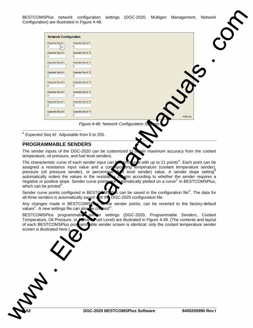
4-52 DGC-2020 BESTCOMSPlus Software 9400200990 Rev I
BESTCOMSPlus network configuration settings (DGC-2020, Multigen Management, Network Configuration) are illustrated in Figure 4-48.
Figure 4-48. Network Configuration Settings
A Expected Seq Id: Adjustable from 0 to 255.
PROGRAMMABLE SENDERS The sender inputs of the DGC-2020 can be customized to obtain maximum accuracy from the coolant temperature, oil pressure, and fuel level senders. The characteristic curve of each sender input can be configured with up to 11 pointsA. Each point can be assigned a resistance input value and a corresponding temperature (coolant temperature sender), pressure (oil pressure sender), or percentage (fuel level sender) value. A sender slope settingB automatically orders the values in the resistance column according to whether the sender requires a negative or positive slope. Sender curve points are automatically plotted on a curveC in BESTCOMSPlus, which can be printedD. Sender curve points configured in BESTCOMSPlus can be saved in the configuration fileE. The data for all three senders is automatically saved with the DGC-2020 configuration file. Any changes made in BESTCOMSPlus to the sender points, can be reverted to the factory-default valuesF. A new settings file can also be createdG. BESTCOMSPlus programmable sender settings (DGC-2020, Programmable Senders, Coolant Temperature, Oil Pressure, or Percent Fuel Level) are illustrated in Figure 4-49. (The contents and layout of each BESTCOMSPlus programmable sender screen is identical; only the coolant temperature sender screen is illustrated here.)
www . El
ectric
alPar
tMan
uals
. com

9400200990 Rev I DGC-2020 BESTCOMSPlus Software 4-53
Figure 4-49. Programmable Senders Settings
A Sender Points: Accepts up to 11 user-defined sender resistance points. B Sender Slope: Positive or Negative causes sender points to be sorted and displayed accordingly. C Sender Point Curve: Automatic plot of sender points data. D Print This Graph: Click to print sender point curve. E Save Cool. Data File: Click to save file containing sender point data. F Load Cool. Settings File: Click to clear all user-defined sender data and revert to the factory-default values. G Create Cool. Settings File: Click to create a new settings file by entering sender point data.
BESTLOGIC+ PROGRAMMABLE LOGIC BESTlogic+ Programmable Logic is used to set all logic functions in the DGC-2020. For detailed information on using BESTlogic+, refer to Section 5, BESTlogic+ Programmable Logic.
Logic Timers Refer to Section 5, BESTlogic+ Programmable Logic, for information on using logic timers.
FILE MANAGEMENT These paragraphs describe file management of settings files, firmware files, and language module files.
Settings Files These paragraphs describe the tasks of opening, uploading, downloading, saving, printing, and comparing of settings files. When opening, uploading, downloading, or saving a settings file, operational settings, as well as BESTlogic+ settings are combined together as a whole. When printing a settings file, only the operational settings are shown. There is a separate print option available on the BESTlogic+ Programmable Logic screen for printing BESTlogic+ settings. For information on solely uploading or downloading BESTlogic+ settings, refer to Section 5, BESTlogic+ Programmable Logic. A settings file conversion is required when DGC-2020 firmware has been changed so that the settings file is compatible with the firmware. For information on converting settings files, see Converting Settings Files, later in this section.
www . El
ectric
alPar
tMan
uals
. com

4-54 DGC-2020 BESTCOMSPlus Software 9400200990 Rev I
Opening a Settings File To open a new instance of a settings file into BESTCOMSPlus, pull down the File menu and choose Open. The Open dialog box appears. This dialog box allows you to use normal Windows® techniques to select the file that you want to open. Select the file and open it and the file settings have been brought into a new instance in BESTCOMSPlus. You may also open a file, by clicking on the Open File icon on the lower menu bar. When done in this manner, you will be asked to upload the settings and logic from the file to the current device. You may choose Yes or No. The settings in the current instance will be overwritten.
Uploading a Settings File To upload a settings file to the DGC-2020, you must first open the file through BESTCOMSPlus or create the file using BESTCOMSPlus. Then pull down the Communication menu and select Upload Settings. You are prompted to enter the password. If the password is correct, the upload begins and the progress bar is shown.
Downloading a Settings File To download a settings file from the DGC-2020, you must pull down the Communication menu and select Download Settings. If the settings in your BESTCOMSPlus have changed, a dialog box will open asking you if want to save the current settings changes. You may choose Yes or No. After you have taken the required action to save or not save the current settings, the downloading is executed.
Saving a Settings File Select Save or Save As from the File pull-down menu. A dialog box pops up allowing you to enter a filename and location to save. Select the Save button to complete the save.
Printing a Settings File To view a preview of the printout, select Print Preview from the File pull-down menu. If you wish to print to a printer, select the printer icon in the upper left corner of the Print Preview screen. You may skip the print preview and go directly to print by pulling down the File menu and selecting Print. A dialog box, Print opens with the typical Windows® choice to setup the properties of printer. Execute this command, as necessary, and then select Print.
Comparing Settings Files BESTCOMSPlus has the ability to compare two different settings files. To use this feature, pull down the Tools menu and select Compare Settings Files. The BESTCOMSPlus Settings Compare Setup dialog box appears (Figure 4-50). Select the location of the first file to compare under Left Settings Source and select the location of the second file to compare under Right Settings Source. If you are comparing a settings file located on your PC hard drive or portable media, click the folder button and navigate to the file. If you want to compare settings downloaded from a unit, click the Select Unit button to set up the communication port. Click the Compare button to compare the selected settings files.
Figure 4-50. BESTCOMSPlus Settings Compare Setup
www . El
ectric
alPar
tMan
uals
. com

9400200990 Rev I DGC-2020 BESTCOMSPlus Software 4-55
A dialog box will appear and notify you if any differences were found. The BESTCOMSPlus Settings Compare dialog box (Figure 4-51) is displayed where you can view all settings (Show All Settings), view only the differences (Show Settings Differences), view all logic (Show All Logic Paths), or view only logic differences (Show Logic Path Differences). Select Close when finished.
Figure 4-51. BESTCOMSPlus Settings Compare
Uploading Device Packages (Firmware/Language Module) A device package contains firmware and a language module. Embedded firmware is the operating program that controls the actions of the DGC-2020. The DGC-2020 stores firmware in nonvolatile flash memory that can be reprogrammed through the communication ports. It is not necessary to replace EPROM chips when updating the firmware with a newer version. Future enhancements to the DGC-2020 functionality may make a firmware update desirable. Because default settings are loaded when DGC-2020 firmware is updated, your settings should be saved in a file prior to upgrading firmware. The language of the front panel LCD can be changed by uploading a different language module into the DGC-2020. The DGC-2020 is capable of storing two language modules in nonvolatile flash memory that can be reprogrammed through the communication ports. The active language module being used for the front panel LCD is selected on the Front Panel HMI setting screen. To access this screen, use the Settings Explorer within BESTCOMSPlus to open the General Settings branch and select the Front Panel HMI screen.
Uploading Firmware/Language Module to Device
If you have obtained an updated device package containing firmware/language module for your device, you may upload it by performing the following steps:
1. Place the DGC-2020 in Off mode. This can be accomplished by clicking the Off button on the Control screen inside the Metering Explorer or by pressing the Off button on the DGC-2020 front panel.
2. Select Upload Device Files from the Communication pull-down menu.
CAUTION If power is lost or communication is interrupted during file transfer, the DGC-2020 will cease operating and will not recover automatically.
www . El
ectric
alPar
tMan
uals
. com

4-56 DGC-2020 BESTCOMSPlus Software 9400200990 Rev I
3. You will be asked to save the current settings file. Select Yes or No. 4. When the Basler Electric Device Package Uploader screen (Figure 4-52) appears, click on the
Open button to browse for the device package you have received from Basler Electric. The Package Files along with File Details are listed. Use the checkboxes to select which files to upload to the DGC-2020.
Figure 4-52. Basler Electric Device Package Uploader
5. Click on the Upload button and the Proceed with Device Upload screen will appear. Select Yes or
No. 6. After selecting Yes, the DGC-2020 Selection screen will appear. Select the communication port to
begin upload. Firmware updating is only possible locally through the USB port. Refer to Figure 4-53.
Figure 4-53. DGC-2020 Selection
7. The Processing, Please Wait… screen is displayed as file(s) are uploaded. See Figure 4-54.
Figure 4-54. Processing, Please Wait…
www . El
ectric
alPar
tMan
uals
. com

9400200990 Rev I DGC-2020 BESTCOMSPlus Software 4-57
8. After file(s) have been uploaded, click the Close button on the Basler Electric Device Package Uploader screen.
METERING EXPLORER The Metering Explorer is a convenient tool within BESTCOMSPlus used to navigate through the following metering screens of the DGC-2020 plug-in. • Engine • Generator • Power • Run Statistics • Status • Inputs
o Local Inputs o Remote Inputs
• Outputs o Local Outputs o Remote Outputs
• Alarms • Event Log • J1939 ECU
o ECU Data o Engine Configuration o Active DTC o Previously Active DTC
• MTU MDEC o MDEC Alarms o MDEC Fault Codes
• Summary • Control • Real Time Clock • Generator Network Status
The Metering Explorer has a “Docking” feature allowing the user to arrange and dock metering screens. A blue transparent square representing the screen being moved, seven arrow buttons, and a tabs button appear when holding down the left mouse button on a metering tab and dragging it out. See Figure 4-55. Table 4-2 explains the call-outs on Figure 4-55.
www . El
ectric
alPar
tMan
uals
. com

4-58 DGC-2020 BESTCOMSPlus Software 9400200990 Rev I
P00
42-1
509
-20-
06
A
C
E
B
D
Figure 4-55. Metering, Docking Options
Table 4-2. Explanation of Call-Outs on Figure 4-55
Call-Out Symbol Explanation
A
Holding the left mouse button down on a metering tab and dragging it to one of the four arrow boxes will place it inside the selected window on the location selected. To place the metering tab as a tab inside the selected window, drop it on the tabs button in the center of the arrow buttons.
B
Holding the left mouse button down on a metering tab and dragging it to this arrow box will place it across the top of the screen. Click on the (thumbtack) to dock it on the top bar. To display a screen that is docked, simply use the mouse to hover the pointer over the tab on the top bar.
C
Holding the left mouse button down on a metering tab and dragging it to this arrow box will place it across the side of the screen. Click on the (thumbtack) to dock it on the side bar. To display a screen that is docked, simply use the mouse to hover the pointer over the tab on the side bar.
D
Holding the left mouse button down on a metering tab and dragging it to this arrow box will place it across the bottom of the screen. Click on the (thumbtack) to dock it on the bottom bar. To display a screen that is docked, simply use the mouse to hover the pointer over the tab on the bottom bar.
E
Holding the left mouse button down on a metering tab and dragging it to anywhere other than an arrow box will place it as a floating metering screen. This floating screen can later be closed by clicking on the in the upper right corner. It may also be dragged to one of the arrow boxes used for docking.
www . El
ectric
alPar
tMan
uals
. com

9400200990 Rev I DGC-2020 BESTCOMSPlus Software 4-59
Engine This screen provides information and metering of engine components. Refer to Figure 4-56.
Figure 4-56. Metering, Engine
Generator This screen provides metering of generator voltages and currents. Refer to Figure 4-57.
Figure 4-57. Metering, Generator
Power This screen provides metering of generator power and power factor. Refer to Figure 4-58.
Figure 4-58. Metering, Power
www . El
ectric
alPar
tMan
uals
. com

4-60 DGC-2020 BESTCOMSPlus Software 9400200990 Rev I
Run Statistics This screen provides Cumulative Run Statistics, Session Run Statistics, and Commission Date. Refer to Figure 4-59. The maintenance interval can be reset through this screen.
Figure 4-59. Metering, Run Statistics
Status This screen indicates status of breakers, modes, and switches. A green LED indicates that the status is TRUE. Refer to Figure 4-60.
Figure 4-60. Metering, Status
www . El
ectric
alPar
tMan
uals
. com

9400200990 Rev I DGC-2020 BESTCOMSPlus Software 4-61
Inputs
Configurable Local Inputs This screen indicates the status of local inputs, configurable input alarms, and configurable input pre-alarms. A red LED indicates that the status is TRUE. Refer to Figure 4-61.
Figure 4-61. Metering, Inputs, Configurable Local Inputs
Configurable Remote Inputs When an optional CEM-2020 (Contact Expansion Module) is connected, the status of the remote inputs, configurable remote input alarms, and configurable remote input pre-alarms are shown on this screen. A red LED indicates that the status is TRUE. Refer to Figure 4-62.
Figure 4-62. Metering, Inputs, Configurable Remote Inputs
www . El
ectric
alPar
tMan
uals
. com
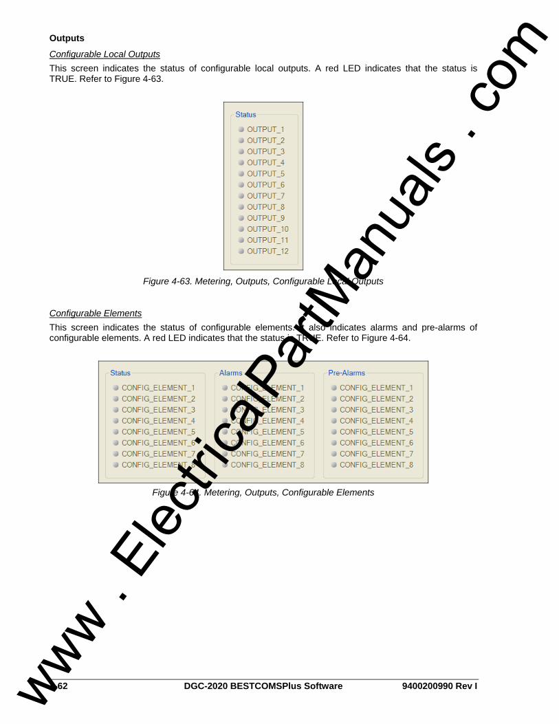
4-62 DGC-2020 BESTCOMSPlus Software 9400200990 Rev I
Outputs
Configurable Local Outputs This screen indicates the status of configurable local outputs. A red LED indicates that the status is TRUE. Refer to Figure 4-63.
Figure 4-63. Metering, Outputs, Configurable Local Outputs
Configurable Elements This screen indicates the status of configurable elements. It also indicates alarms and pre-alarms of configurable elements. A red LED indicates that the status is TRUE. Refer to Figure 4-64.
Figure 4-64. Metering, Outputs, Configurable Elements
www . El
ectric
alPar
tMan
uals
. com

9400200990 Rev I DGC-2020 BESTCOMSPlus Software 4-63
Configurable Remote Outputs When an optional CEM-2020 (Contact Expansion Module) is connected, the status of the configurable remote outputs are shown on this screen. A red LED indicates that the status is TRUE. Refer to Figure 4-65.
Figure 4-65. Metering, Outputs, Configurable Remote Outputs
www . El
ectric
alPar
tMan
uals
. com

4-64 DGC-2020 BESTCOMSPlus Software 9400200990 Rev I
Alarms This screen indicates the status of Alarms, Pre-Alarms, Sender Fail, and Generator Protection. A green LED indicates that the status is TRUE. Alarms and pre-alarms are reset when the DGC-2020 is set to the Off mode. The Sync Fail at Gen Breaker, Gen Breaker Fail to Open, Gen Breaker Fail to Close, Sync Fail at Mains Breaker, Mains Breaker Fail to Open, and Mains Breaker Fail to Close pre-alarms can be reset by pressing the Reset key on the front panel HMI. Refer to Figure 4-66.
Figure 4-66. Metering, Alarms
Event Log The event log provides a historical record of event occurrences detected by the DGC-2020. It is saved in nonvolatile memory so that is will not be affected if power is removed. Thirty event records are retained
www . El
ectric
alPar
tMan
uals
. com

9400200990 Rev I DGC-2020 BESTCOMSPlus Software 4-65
and each record contains a time stamp of the first and last event occurrence, and the number of occurrences for each event. In addition, each record contains details of the time, date, and engine hours for the most recent 30 occurrences of the event. The number of occurrences stops incrementing at 99. If an event occurs which is of a type that differs from those in the 30 records in memory, the record that has the oldest “last” event occurrence is removed from the log, and the new category takes its place. Since 30 event records with up to 99 occurrences each are retained in memory, a history of nearly 3,000 specific events are retained in the DGC-2020. Detailed occurrence information is retained for the most recent 30 occurrences of each event record, and there are 30 event records; thus the time, date and engine hours details for up to 900 specific event occurrences is retained in the event log. The user can download the event log data into BESTCOMSPlus for viewing, and then save the event logs as files. The Options button is used to save the entire event log to a file, or to save the list to the computer clipboard making it available for insertion into other software applications. It is possible to copy a portion of the log to the computer clipboard by selecting the desired portion with the mouse then using the Options->Copy Selection feature. The Download button refreshes the event log list by performing a fresh download of the list from the DGC-2020. The Clear button gives the user the option of clearing selected or all event logs. Refer to Figure 4-67.
Figure 4-67. Metering, Event Log, Sorted by Date
When viewed with BESTCOMSPlus, the event log can be sorted by Event ID, Description, Occurrence, Date, or Engine Hours. Selecting event log sorted by Date yields a list of all event occurrences in sequential order. This is a view that one would see in a typical “sequence of events” type of event log. Figure 4-67 shows the sequential list resulting from sorting by Date. Sorting by engine hours also results in a sequential list, where the sequence is in terms of engine hours rather than calendar date and time. Selecting sorting by Event ID or Description allows one to view all the occurrences of a particular event type in their order of occurrence. In this view, one can see at a glance the times and dates of the occurrences of one type of event. For example, from Figure 4-68, if one wanted to know when all occurrences of Speed Sender Failures occurred, the information readily available without having to sift through all the occurrences of unrelated events as would have to be done in a rolling log implementation. This is apparent in Figure 4-67.
www . El
ectric
alPar
tMan
uals
. com

4-66 DGC-2020 BESTCOMSPlus Software 9400200990 Rev I
Figure 4-68. Metering, Event Log, Sorted by Event ID
J1939 ECU The ECU reports operating information to the DGC-2020 through the CAN interface when the ECU is configured for Volvo Penta. Operating parameters and diagnostic information, if supported by the ECU, are decoded and displayed on these screens.
ECU Data This screen displays ECU Lamp Status and ECU Data. Refer to Figure 4-69.
Figure 4-69. Metering, ECU Data
www . El
ectric
alPar
tMan
uals
. com

9400200990 Rev I DGC-2020 BESTCOMSPlus Software 4-67
Engine Configuration This screen displays Engine Configuration. Refer to Figure 4-70.
Figure 4-70. Metering, Engine Configuration
Active DTC and Previously Active DTC This screen is used for viewing, downloading, and clearing DTC (Diagnostic Trouble Codes). Refer to Figure 4-71.
Figure 4-71. Metering, Download DTC
www . El
ectric
alPar
tMan
uals
. com

4-68 DGC-2020 BESTCOMSPlus Software 9400200990 Rev I
MTU MDEC The MTU MDEC reports operating information to the DGC-2020 through the CAN interface when the ECU is configured for MTU MDEC. Operating parameters and diagnostic information, if supported by the MTU MDEC, are decoded and displayed on these screens.
MDEC Alarms MDEC Pre-Alarms and MDEC Alarms are reported on this screen. Refer to Figure 4-72.
Figure 4-72. Metering, MDEC Alarms
MDEC Fault Codes MDEC Fault Codes can be viewed and downloaded on this screen. Refer to Figure 4-73.
Figure 4-73. Metering, MDEC Fault Codes
www . El
ectric
alPar
tMan
uals
. com

9400200990 Rev I DGC-2020 BESTCOMSPlus Software 4-69
Summary This screen displays a metering summary. Refer to Figure 4-74.
Figure 4-74. Metering, Summary
www . El
ectric
alPar
tMan
uals
. com

4-70 DGC-2020 BESTCOMSPlus Software 9400200990 Rev I
Control Controls for stopping/starting the engine, controls for opening/closing breakers, and controls for opening/closing switches are accessed through the Control branch.
Figure 4-75. Metering, Control
The following controls are available by using the Metering Explorer in BESTCOMSPlus to open the Control branch. Refer to Figure 4-75.
1. The user has control to stop the generator in case of emergency by clicking on the Emergency Stop button.
2. The engine can be started and stopped by clicking on the Start and Stop buttons.
3. The engine can be set to Run, Auto, or Off. 4. There are controls for opening and closing the
generator breaker and mains breaker. A green LED indicates that the breaker is open. A red LED indicates that the breaker is closed
5. Switches 1 through 4 can be opened or closed by clicking on the Open or Close buttons. A red LED indicates that a switch is closed.
When running BESTCOMSPlus in Live mode, these buttons will interact with the DGC-2020 in real time.
Real Time Clock Settings for Date and Time are made here. Refer to Figure 4-76.
Figure 4-76. Metering, Real Time Clock
www . El
ectric
alPar
tMan
uals
. com

9400200990 Rev I DGC-2020 BESTCOMSPlus Software 4-71
Generator Network Status This screen (Figure 4-77) displays the detected sequencing IDs of the LSM-2020’s on the network. This can only be accomplished when an optional LSM-2020 (Load Share Module) is connected to the DGC-2020 and actively communicating to the generator network. The Options button is used to copy or save the list of sequencing IDs. The Download button refreshes the list of sequencing IDs.
Figure 4-77. Metering, Generator Network Status
UPDATING BESTCOMSPlus SOFTWARE Future enhancements to DGC-2020 functionality may make firmware updates desirable. Enhancements to DGC-2020 firmware typically coincide with enhancements to the DGC-2020 plug-in for BESTCOMSPlus. When a DGC-2020 is updated with the latest version of firmware, the latest version of the DGC-2020 plug-in for BESTCOMSPlus should also be obtained. If you obtained a CD-ROM containing firmware from Basler Electric, then that CD-ROM will also contain the corresponding version of the DGC-2020 plug-in with BESTCOMSPlus software. The DGC-2020 plug-in with BESTCOMSPlus can also be downloaded from the Basler Electric web site (http://www.basler.com). An outline form can be completed to obtain a password for downloading the software from the Basler Electric web site. BESTCOMSPlus also has a built in tool that will check for program updates if you are connected to the World Wide Web. The Check for Updates tool is located in the Tools drop-down menu.
CONVERTING SETTINGS FILES A settings file conversion is required when DGC-2020 firmware has been changed. To make the settings file compatible with the firmware, perform the following:
1. Using BESTCOMSPlus, open the settings file to be converted from the top menu bar via File, Open. Do not connect to the DGC-2020 at this time.
2. Working offline, use the Settings Explorer to open the Device Info screen. Click on the pull-down menu under Application Version and select the version of firmware that the DGC-2020 holds.
3. Use the Settings Explorer to open the BESTlogic+ Programmable Logic screen. Verify that the three status LEDs located in the lower right corner are green indicating that the logic is ready to be saved to a file. If all three status LEDs are not green, click on the Save button located on the BESTlogic+ toolbar, correct any logic diagram errors, and then click Save again. Note that this step saves the logic in BESTCOMSPlus memory, not to a file.
4. It is recommended to save the old settings file. From the top menu bar select File, Save As, and enter a name for the new settings file.
5. Connect to the DGC-2020 and upload the new settings file.
www . El
ectric
alPar
tMan
uals
. com
4-72 DGC-2020 BESTCOMSPlus Software 9400200990 Rev I
This page intentionally left blank.
www . El
ectric
alPar
tMan
uals
. com

9400200990 Rev I DGC-2020 BESTlogic+ Programmable Logic i
SECTION 5 • BESTlogic+ PROGRAMMABLE LOGIC
TABLE OF CONTENTS SECTION 5 • BESTlogic+ PROGRAMMABLE LOGIC............................................................................. 5-1
INTRODUCTION.................................................................................................................................... 5-1 OVERVIEW OF BESTlogic+.................................................................................................................. 5-1
BESTlogic+ Composition ................................................................................................................... 5-2 I/O ................................................................................................................................................... 5-2 Components ................................................................................................................................... 5-7 Elements......................................................................................................................................... 5-9
LOGIC SCHEMES ............................................................................................................................... 5-11 The Active Logic Scheme................................................................................................................. 5-11 Copying and Renaming Preprogrammed Logic Schemes............................................................... 5-12 Sending and Retrieving Logic Schemes .......................................................................................... 5-12
Retrieving a Logic Scheme from the DGC-2020 .......................................................................... 5-12 Sending a Logic Scheme to the DGC-2020 ................................................................................. 5-12
PROGRAMMING BESTlogic+ ............................................................................................................. 5-12 I/O..................................................................................................................................................... 5-13
Input Objects................................................................................................................................. 5-13 Output Objects.............................................................................................................................. 5-13 Alarms........................................................................................................................................... 5-13 Pre-Alarms.................................................................................................................................... 5-13 Senders......................................................................................................................................... 5-13
Components ..................................................................................................................................... 5-13 Logic Gates................................................................................................................................... 5-13 Latches ......................................................................................................................................... 5-13 Pickup and Dropout Timers .......................................................................................................... 5-13 Logic Comment Block................................................................................................................... 5-14
Elements........................................................................................................................................... 5-14 Protective Elements...................................................................................................................... 5-14 Control Elements .......................................................................................................................... 5-14 Logic Alarm Elements................................................................................................................... 5-15 Configurable Elements ................................................................................................................. 5-15 Other ............................................................................................................................................. 5-15
BESTlogic+ FILE MANAGEMENT....................................................................................................... 5-15 Saving a BESTlogic+ File ............................................................................................................. 5-15 Opening a BESTlogic+ File .......................................................................................................... 5-15 Protecting a BESTlogic+ File........................................................................................................ 5-15 Uploading a BESTlogic+ File........................................................................................................ 5-15 Downloading a BESTlogic+ File ................................................................................................... 5-15 Printing a BESTlogic+ File............................................................................................................ 5-16 Clearing the On-Screen Logic Diagram........................................................................................ 5-16
BESTlogic+ EXAMPLES...................................................................................................................... 5-16 Example 1 - AVR Logic Block Connections ..................................................................................... 5-16 Example 2 - AND Gate Connections................................................................................................ 5-16 Example 3 - Multiple Logic Connections .......................................................................................... 5-16
Figures Figure 5-1. BESTlogic+ Programmable Logic Tree Branch ...................................................................... 5-1 Figure 5-2. Pickup and Dropout Timer Logic Blocks ............................................................................... 5-14 Figure 5-3. Logic Comment Block ........................................................................................................... 5-14 Figure 5-4. BESTlogic+ Programmable Logic Toolbar............................................................................ 5-15 Figure 5-5. Example 1 - AVR Logic Block Connections.......................................................................... 5-16 Figure 5-6. Example 2 - AND Gate Connections .................................................................................... 5-16 Figure 5-7. Example 3 - Multiple Logic Connections............................................................................... 5-17
www . El
ectric
alPar
tMan
uals
. com

ii DGC-2020 BESTlogic+ Programmable Logic 9400200990 Rev I
Tables Table 5-1. I/O Group, Names and Descriptions ........................................................................................ 5-2 Table 5-2. Components Group, Names and Descriptions......................................................................... 5-7 Table 5-3. Elements Group, Names and Descriptions .............................................................................. 5-9 Table 5-4. Status LEDs ........................................................................................................................... 5-13
www . El
ectric
alPar
tMan
uals
. com

9400200990 Rev I DGC-2020 BESTlogic+ Programmable Logic 5-1
SECTION 5 • BESTlogic+ PROGRAMMABLE LOGIC
INTRODUCTION BESTlogic+ Programmable Logic is a programming method used for managing the input, output, protection, control, monitoring, and reporting capabilities of Basler Electric's DGC-2020 Digital Genset Controller. Each DGC-2020 has multiple, self-contained logic blocks that have all of the inputs and outputs of its discrete component counterpart. Each independent logic block interacts with control inputs and hardware outputs based on logic variables defined in equation form with BESTlogic+. BESTlogic+ equations entered and saved in the DGC-2020 system's nonvolatile memory integrate (electronically wire) the selected or enabled protection and control blocks with control inputs and hardware outputs. A group of logic equations defining the logic of the DGC-2020 is called a logic scheme. One default active logic scheme is pre-loaded into the DGC-2020. This scheme is configured for a typical protection and control application and virtually eliminates the need for "start-from-scratch" programming. BESTCOMSPlus can be used to open a logic scheme that was previously saved as a file and upload it to the DGC-2020. The default logic scheme can also be customized to suit your application. Detailed information about logic schemes is provided later in this section. BESTlogic+ is not used to define the operating settings (modes, pickup thresholds, and time delays) of the individual protection and control functions. Operating settings and logic settings are interdependent but separately programmed functions. Changing logic settings is similar to rewiring a panel and is separate and distinct from making the operating settings that control the pickup thresholds and time delays of a DGC-2020. Detailed information about operating settings is provided in Section 3, Functional Description.
OVERVIEW OF BESTlogic+ BESTlogic+ settings are made through BESTCOMSPlus. Use the Settings Explorer to open the BESTlogic+ Programmable Logic tree branch as shown in Figure 5-1. The BESTlogic+ Programmable Logic screen contains a logic library for opening and saving logic files, tools for creating and editing logic documents, and protection settings.
Figure 5-1. BESTlogic+ Programmable Logic Tree Branch
www . El
ectric
alPar
tMan
uals
. com

5-2 DGC-2020 BESTlogic+ Programmable 9400200990 Rev I
BESTlogic+ Composition There are three main groups of objects used for programming BESTlogic+. These groups are I/O, Components, and Elements. For details on how these objects are used to program BESTlogic+, see the paragraphs on Programming BESTlogic+.
I/O This group contains Input Objects, Output Objects, Alarms, Pre-Alarms, and Senders. Table 5-1 lists the names and descriptions of the objects in the I/O group.
Table 5-1. I/O Group, Names and Descriptions Name Description Symbol
Input Objects
Logic 0 Always FALSE (Low).
Logic 1 Always TRUE (High).
Physical Inputs IN1 - IN16
TRUE when Physical Input x is active.
Remote Inputs IN17 - IN26
True when Remote Input x is active. (Available when an optional CEM-2020 is connected.)
Virtual Inputs VIN1 - VIN4
TRUE when Virtual Input x is active.
Status Input ATS Input
TRUE when the ATS (Auto Transfer Switch) input is TRUE.
Status Input Audible Horn
TRUE when the Audible Horn is active.
Status Input Auto Mode
TRUE when the DGC-2020 is in Auto Mode.
Status Input Auto Restart
TRUE when the Automatic Restart function is active.
Status Input Battery Charger Fail
TRUE when the Battery Charger Fail input is TRUE.
Status Input Battle Override
TRUE when the Battle Override input is TRUE.
Status Input Bus Dead
TRUE when the Bus Dead condition settings have been exceeded.
Status Input Bus Fail
TRUE when the Bus Fail condition settings have been exceeded.
Status Input Bus Stable
TRUE when the Bus Stable condition settings have been exceeded.
Status Input Contact Expansion Module Connected
TRUE when an optional CEM-2020 is connected to the DGC-2020.
www . El
ectric
alPar
tMan
uals
. com

9400200990 Rev I DGC-2020 BESTlogic+ Programmable Logic 5-3
Name Description Symbol
Status Input Cool Down Timer Active
TRUE when the Cool Down Timer is timing out.
Status Input Emergency Stop
TRUE when the Emergency Stop button has been pressed.
Status Input Engine Running
TRUE while the Engine is Running.
Status Input EPS Supplying Load
TRUE while the EPS is supplying load.
Status Input Fuel Leak
TRUE when the Fuel Leak Detect input is TRUE.
Status Input Generator Dead
TRUE when the Gen Dead condition settings have been exceeded.
Status Input Generator Fail
TRUE when the Gen Fail condition settings have been exceeded.
Status Input Generator Stable
TRUE when the Gen Stable condition settings have been exceeded.
Status Input Generator Test Loaded
TRUE when the Exercise Timer has started the generator and run with load is selected.
Status Input Generator Test
TRUE when the Exercise Timer has started the generator.
Status Input Global Low Coolant Level
TRUE when the Low Coolant Level input is TRUE.
Status Input Ground Delta Override
TRUE when the Grounded Delta Override input is TRUE.
Status Input Load Share Module AVR Output Limit
TRUE when the LSM-2020 AVR Output Limit settings have been exceeded.
Status Input Load Share Module Connected
TRUE when an optional LSM-2020 is connected to the DGC-2020.
Status Input Load Share Module Governor Output Limit
TRUE when the LSM-2020 Governor Output Limit settings have been exceeded.
Status Input Low Line Override
TRUE when the Low Line Override input is TRUE.
Status Input Off Mode
TRUE when the DGC-2020 is in Off Mode.
www . El
ectric
alPar
tMan
uals
. com

5-4 DGC-2020 BESTlogic+ Programmable 9400200990 Rev I
Name Description Symbol
Status Input Pre Start Condition in Effect
TRUE while in the Pre-Start state.
Status Input Reset Active
TRUE while the Reset button on the HMI is pressed.
Status Input Run Mode
TRUE when the DGC-2020 is in Run Mode.
Status Input Single Phase AC Sensing Override
TRUE when the Single Phase AC Override input is TRUE.
Status Input Single Phase Connection Override
TRUE when the Single Phase Override input is TRUE.
Status Input Switch not in Auto
TRUE when the DGC-2020 is not in Auto Mode.
Output Objects
Physical Outputs OUT1 - OUTx
Physical Outputs 1 through 7 (style xxAxxxxx) or 1 through 15 (style xxBxxxxx).
Remote Outputs OUT13 - OUT36
True when Remote Output x is active. (Available when an optional CEM-2020 is connected.)
Alarms
Auto Restart Fail TRUE after the Automatic Restart function fails to restart the generator.
Battery Charger Fail
TRUE when the Battery Charger Fail function is configured as an Alarm and the activation delay has expired.
Coolant Level Sender Fail
TRUE when a low coolant level error status code is received from the ECU. Canbus must be enabled.
Coolant Temp Sender Fail
TRUE when the Coolant Temp Sender Fail is configured as an Alarm and the activation delay has expired.
ECU Comm Loss TRUE when communication to ECU has been lost.
ECU Shutdown TRUE when ECU has Shutdown the engine.
Emergency Stop TRUE when the Emergency Stop button has been pressed.
Fuel Leak TRUE when the Fuel Leak Detect function is configured as an Alarm and the activation delay has expired.
Fuel Level Sender Fail
TRUE when the Fuel Level Sender Fail is configured as an Alarm and the activation delay has expired.
www . El
ectric
alPar
tMan
uals
. com

9400200990 Rev I DGC-2020 BESTlogic+ Programmable Logic 5-5
Name Description Symbol
Global Alarm TRUE when one or more Alarms are set.
Global Sender Fail TRUE when one or more of the Sender Fails are configured as Alarms and are TRUE.
Hi Coolant Temp TRUE when the High Coolant Temp Alarm settings have been exceeded.
Low Coolant Level
TRUE when the Low Coolant Level function is configured as an Alarm and the activation delay has expired. In addition, TRUE when Canbus is enabled and the Low Coolant Level Alarm threshold has been exceeded.
Low Fuel Level TRUE when the Low Fuel Level Alarm settings have been exceeded.
Low Oil Pressure TRUE when the Low Oil Pressure Alarm settings have been exceeded.
Oil Pressure Sender Fail
TRUE when the Oil Pressure Sender Fail is configured as an Alarm and the activation delay has expired.
Overcrank TRUE when an Overcrank condition exists.
Overspeed TRUE when the Overspeed Alarm settings have been exceeded.
Speed Sender Fail TRUE when the Speed Sender Fail activation delay has expired.
Voltage Sensing Fail
TRUE when the Voltage Sensing Fail is configured as an Alarm and the activation delay has expired.
Pre-Alarms
Battery Charger Fail
TRUE when the Battery Charger Fail function is configured as a Pre-Alarm and the activation delay has expired.
Battery Overvoltage
TRUE when the Battery Overvoltage Pre-Alarm threshold has been exceeded.
Contact Expansion Module Comm Fail
TRUE when communication from the CEM-2020 to the DGC-2020 has been lost.
Coolant Temp Sender Fail
TRUE when the Coolant Temp Sender Fail is configured as a Pre-Alarm and the activation delay has expired.
Diag Trouble Code TRUE when a Diagnostic Trouble Code exists.
ECU Com Loss TRUE when communication to ECU has been lost.
www . El
ectric
alPar
tMan
uals
. com

5-6 DGC-2020 BESTlogic+ Programmable 9400200990 Rev I
Name Description Symbol
Engine KW Over Load 1
TRUE when the Engine KW Overload 1 Pre-Alarm settings have been exceeded.
Engine KW Over Load 2
TRUE when the Engine KW Overload 2 Pre-Alarm settings have been exceeded.
Engine KW Over Load 3
TRUE when the Engine KW Overload 3 Pre-Alarm settings have been exceeded.
Fuel Leak TRUE when the Fuel Leak Detect function is configured as a Pre-Alarm and the activation delay has expired.
Fuel Level Sender Fail
TRUE when the Fuel Level Sender Fail is configured as a Pre-Alarm and the activation delay has expired.
Global Pre-Alarm TRUE when one or more Pre-Alarms are set.
Hi Coolant Temp TRUE when the High Coolant Temp Pre-Alarm threshold has been exceeded.
High Fuel Level TRUE when the High Fuel Level Pre-Alarm settings have been exceeded.
Intergenset Comm Fail
TRUE when an individual generator detects that it had been connected to a generator network, but has lost the connection.
Load Share Module Comm Fail
TRUE when communication from the LSM-2020 to the DGC-2020 has been lost.
Low Battery Voltage
TRUE when the Low Battery Voltage Pre-Alarm settings have been exceeded.
Low Coolant Level
TRUE when the Low Coolant Level function is configured as a Pre-Alarm and the activation delay has expired. In addition, TRUE when Canbus is enabled and the Low Coolant Level Pre-Alarm threshold has been exceeded.
Low Coolant Temp TRUE when the Low Coolant Temp Pre-Alarm threshold has been exceeded.
Low Fuel Level TRUE when the Low Fuel Level Pre-Alarm threshold has been exceeded.
Low Oil Pressure TRUE when the Low Oil Pressure Pre-Alarm threshold has been exceeded.
Maintenance Interval
TRUE when the Maintenance Interval Pre-Alarm threshold has been exceeded.
MPU Fail TRUE when the MPU has failed.
Multiple Contact Expansion Modules Detected
TRUE when more than one CEM-2020 is connected.
www . El
ectric
alPar
tMan
uals
. com

9400200990 Rev I DGC-2020 BESTlogic+ Programmable Logic 5-7
Name Description Symbol
Multiple Load Share Modules Detected
TRUE when more than one LSM-2020 is connected.
Network ID Missing Error
TRUE if an expected sequence ID of an optional LSM-2020 is not detected on the network. Expected sequence IDs are entered on the Network Configuration screen.
Network ID Repeat Error
TRUE if two or more optional LSM-2020’s report the same expected sequence ID. Expected sequence IDs are entered on the Network Configuration screen.
Oil Pressure Sender Fail
TRUE when the Oil Pressure Sender Fail is configured as a Pre-Alarm and the activation delay has expired.
Voltage Sensing Fail
TRUE when the Voltage Sensing Fail is configured as a Pre-Alarm and the activation delay has expired.
Weak Battery TRUE when the Weak Battery Voltage Pre-Alarm settings have been exceeded.
Senders
Coolant Temp Sender Fail
TRUE when the Coolant Temp Sender Fail is configured as either a Pre-Alarm or Alarm and the activation delay has expired.
Fuel Level Sender Fail
TRUE when the Fuel Level Sender Fail is configured as either a Pre-Alarm or Alarm and the activation delay has expired.
Oil Pressure Sender Fail
TRUE when the Oil Pressure Sender Fail is configured as either a Pre-Alarm or Alarm and the activation delay has expired.
Speed Sender Fail TRUE when the Speed Sender Fail activation delay has expired.
Voltage Sensing Fail
TRUE when the Voltage Sensing Fail is configured as either a Pre-Alarm or Alarm and the activation delay has expired.
Components This group contains Logic Gates, Pickup and Dropout Timers, Latches, and Comment Blocks. Table 5-2 lists the names and descriptions of the objects in the Components group.
Table 5-2. Components Group, Names and Descriptions Name Description Symbol
Logic Gates
AND
Input Output0 0 0 0 1 0 1 0 0 1 1 1
NAND
Input Output0 0 1 0 1 1 1 0 1 1 1 0
www . El
ectric
alPar
tMan
uals
. com

5-8 DGC-2020 BESTlogic+ Programmable 9400200990 Rev I
Name Description Symbol
OR
Input Output0 0 0 0 1 1 1 0 1 1 1 1
NOR
Input Output0 0 1 0 1 0 1 0 0 1 1 0
XOR
Input Output0 0 0 0 1 1 1 0 1 1 1 0
XNOR
Input Output0 0 1 0 1 0 1 0 0 1 1 1
NOT Input Output
0 1 1 0
Pickup and Dropout Timers
Drop Out Timer Used to set a delay in the logic.
Pickup Up Timer Used to set a delay in the logic.
Latches
Reset Priority Latch Resets latch.
Set Priority Latch Sets latch.
www . El
ectric
alPar
tMan
uals
. com

9400200990 Rev I DGC-2020 BESTlogic+ Programmable Logic 5-9
Other
Comment Block Enter user comments.
Elements This group contains logic block objects for the 51, 27, 47, 59, 81, 32, and 40 Elements. It also contains logic block objects for Generator Breaker, AVR Raise/Lower, Governor Raise/Lower, Logic Alarm, Logic Pre-Alarm, Modem, Configurable Elements, AUTO Mode, OFF Mode, RUN Modem, Parallel to Mains, and Run with Load. Table 5-3 lists the names and descriptions of the objects in the Elements group.
Table 5-3. Elements Group, Names and Descriptions Name Description Symbol
Protective Element Objects
27-1TRIP TRUE when the 27-1 undervoltage is in a TRIP condition. Connect to another logic block input.
27-2TRIP TRUE when the 27-2 undervoltage is in a TRIP condition. Connect to another logic block input.
32TRIP TRUE when the 32 reverse power is in a TRIP condition. Connect to another logic block input.
40TRIP TRUE when the 40Q loss of excitation is in a TRIP condition. Connect to another logic block input.
47TRIP (Optional)
TRUE when the 47 phase imbalance is in a TRIP condition. Connect to another logic block input.
51-1TRIP (Optional)
TRUE when the 51-1 overcurrent is in a TRIP condition. Connect to another logic block input.
51-2TRIP (Optional)
TRUE when the 51-2 overcurrent is in a TRIP condition. Connect to another logic block input.
59-1TRIP TRUE when the 59-1 overvoltage is in a TRIP condition. Connect to another logic block input.
www . El
ectric
alPar
tMan
uals
. com

5-10 DGC-2020 BESTlogic+ Programmable 9400200990 Rev I
Name Description Symbol
59-2TRIP TRUE when the 59-2 overvoltage is in a TRIP condition. Connect to another logic block input.
81TRIP TRUE when the 81 frequency is in a TRIP condition. Connect to another logic block input.
Other Element Objects
AUTOMODE When this input is TRUE, and the DGC-2020 is in OFF mode, the DGC-2020 will switch to AUTO mode. This is a pulsed input. It does not need to be held after the desired mode switch has occurred.
AVR Can be connected to inputs of other logic blocks. When the AVR is being raised, the Raise output is TRUE. When being lowered, the Lower output is TRUE.
CONFELMNT
Eight configurable elements can be set up on the Configurable Elements screen using the Settings Explorer. A configurable element can be programmed to annunciate an alarm or pre-alarm when the input is TRUE.
GENBRK Used to control the generator breaker. Connect the inputs and outputs to inputs and outputs of other logic blocks.
GOVR Can be connected to inputs of other logic blocks. When the Governor is being raised, the Raise output is TRUE. When being lowered, the Lower output is TRUE.
LOGICALM When this input is TRUE, the DGC-2020 goes into an Alarm condition.
LOGICPALM When this input is TRUE, the DGC-2020 goes into a Pre-alarm condition.
www . El
ectric
alPar
tMan
uals
. com
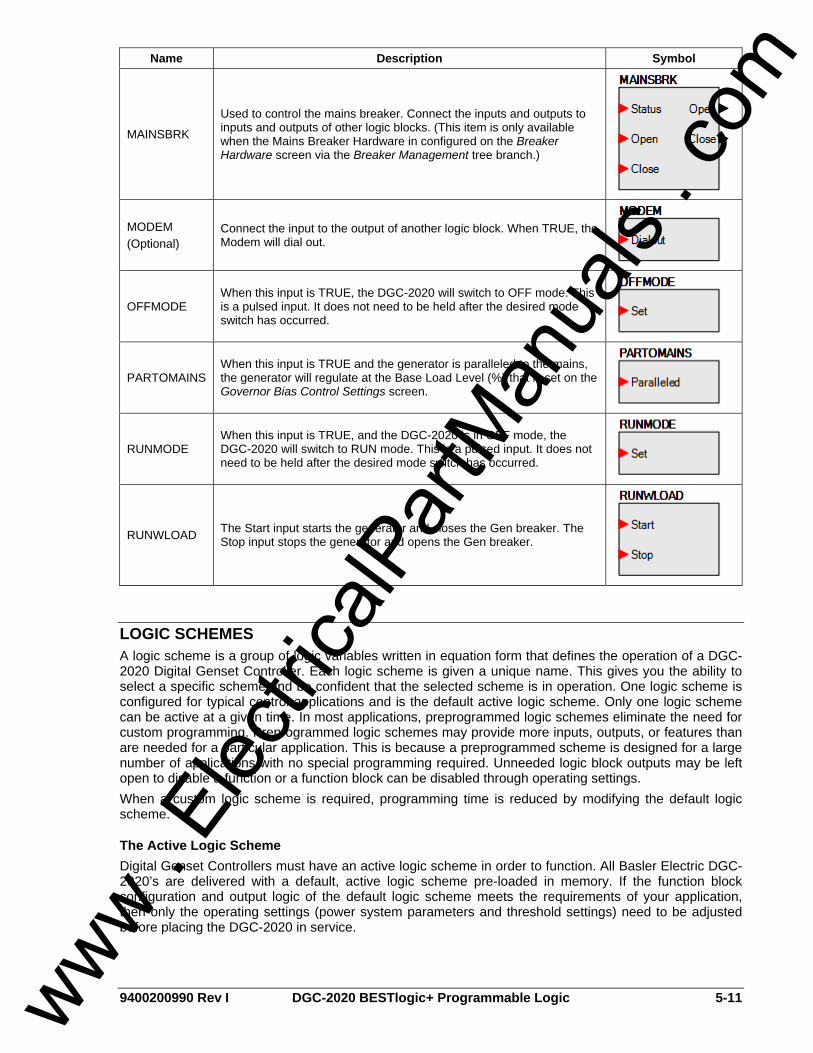
9400200990 Rev I DGC-2020 BESTlogic+ Programmable Logic 5-11
Name Description Symbol
MAINSBRK
Used to control the mains breaker. Connect the inputs and outputs to inputs and outputs of other logic blocks. (This item is only available when the Mains Breaker Hardware in configured on the Breaker Hardware screen via the Breaker Management tree branch.)
MODEM (Optional)
Connect the input to the output of another logic block. When TRUE, the Modem will dial out.
OFFMODE When this input is TRUE, the DGC-2020 will switch to OFF mode. This is a pulsed input. It does not need to be held after the desired mode switch has occurred.
PARTOMAINS When this input is TRUE and the generator is paralleled to the mains, the generator will regulate at the Base Load Level (%) that is set on the Governor Bias Control Settings screen.
RUNMODE When this input is TRUE, and the DGC-2020 is in OFF mode, the DGC-2020 will switch to RUN mode. This is a pulsed input. It does not need to be held after the desired mode switch has occurred.
RUNWLOAD The Start input starts the generator and closes the Gen breaker. The Stop input stops the generator and opens the Gen breaker.
LOGIC SCHEMES A logic scheme is a group of logic variables written in equation form that defines the operation of a DGC-2020 Digital Genset Controller. Each logic scheme is given a unique name. This gives you the ability to select a specific scheme and be confident that the selected scheme is in operation. One logic scheme is configured for typical control applications and is the default active logic scheme. Only one logic scheme can be active at a given time. In most applications, preprogrammed logic schemes eliminate the need for custom programming. Preprogrammed logic schemes may provide more inputs, outputs, or features than are needed for a particular application. This is because a preprogrammed scheme is designed for a large number of applications with no special programming required. Unneeded logic block outputs may be left open to disable a function or a function block can be disabled through operating settings. When a custom logic scheme is required, programming time is reduced by modifying the default logic scheme.
The Active Logic Scheme Digital Genset Controllers must have an active logic scheme in order to function. All Basler Electric DGC-2020’s are delivered with a default, active logic scheme pre-loaded in memory. If the function block configuration and output logic of the default logic scheme meets the requirements of your application, then only the operating settings (power system parameters and threshold settings) need to be adjusted before placing the DGC-2020 in service.
www . El
ectric
alPar
tMan
uals
. com

5-12 DGC-2020 BESTlogic+ Programmable 9400200990 Rev I
Copying and Renaming Preprogrammed Logic Schemes Copying a saved logic scheme to the active logic (Logic Name) and assigning a unique name is accomplished by loading the saved logic scheme into BESTCOMSPlus and then typing over the logic scheme's name. Changes are not activated until the new settings have been saved and uploaded to the device.
Sending and Retrieving Logic Schemes
Retrieving a Logic Scheme from the DGC-2020 To retrieve settings from the DGC-2020, the DGC-2020 must be connected to a computer through a communications port. Once the necessary connections are made, settings can be downloaded from the DGC-2020 by selecting Download Settings on the Communication pull-down menu.
Sending a Logic Scheme to the DGC-2020 To send settings to the DGC-2020, the DGC-2020 must be connected to a computer through a communications port. Once the necessary connections are made, settings can be uploaded to the DGC-2020 by selecting Upload Settings on the Communication pull-down menu.
PROGRAMMING BESTLOGIC+ BESTCOMSPlus is used to program BESTlogic+. Using BESTCOMSPlus is analogous to physically attaching wire between discrete DGC-2020 terminals. To program BESTlogic+, use the Settings Explorer within BESTCOMSPlus to open the BESTlogic+ Programmable Logic tree branch as shown in Figure 5-1. The drag and drop method is used to connect a variable or series of variables to the logic inputs, outputs, components, and elements. To draw a wire/link from port to port (triangles), click the left mouse button on a port, pull the wire onto another port, and release the left mouse button. A red port indicates that a connection to the port is required or missing. A black port indicates that a connection to the port is not required. Drawing wires/links from input to input or output to output is not allowed. Only one wire/link can be connected to any one output. If the proximity of the endpoint of the wire/link is not exact, it may attach to an unintended port. If an element is disabled, it will have a yellow X on it. To enable the element, navigate to the settings page for that element. The view of the Main Logic, Physical Outputs, and Remote Outputs can be automatically arranged by clicking the right mouse button on the window and selecting Auto-Layout. The following must be met before BESTCOMSPlus will allow logic to be uploaded to the DGC-2020: • A minimum of two inputs and a maximum of four inputs on any multi-port (AND, OR, NAND, NOR,
XOR, and XNOR) gate. • A maximum of five logic levels for any particular path. A path being an input block or an output side of
an element block through gates to an output block or an input side of an element block. This is to include any OR gates on the Physical Output or Remote Output tab/pages, but not the matched pairs of Physical Output blocks or Remote Output blocks.
CAUTION Always remove the DGC-2020 from service prior to changing or modifying the active logic scheme. Attempting to modify a logic scheme while the DGC-2020 is in service could generate unexpected or unwanted outputs.
CAUTION Modifying a logic scheme in BESTCOMSPlus does not automatically make that scheme active in the DGC-2020. The modified scheme must be uploaded into the DGC-2020. See the paragraphs on Sending and Retrieving Logic Schemes later in this section.
www . El
ectric
alPar
tMan
uals
. com

9400200990 Rev I DGC-2020 BESTlogic+ Programmable Logic 5-13
• Only ten gates per logic level. All output blocks and input sides of element blocks are at the maximum logic level of the diagram. All gates are pushed forward/upwards in logic levels and buffered to reach the final output block or element block if needed.
• At all levels there can only be 64 used link/wired or endpoints. Endpoints being inputs, outputs, both sides of element blocks.
Three status LEDs are located in the lower right corner of the BESTlogic+ window. These LEDs show the Logic Save Status, Logic Diagram Status, and Logic Layer Status. Table 5-4 defines the colors for each LED.
Table 5-4. Status LEDs
LED Color Definition
Yellow Logic has changed since last save. Logic Save Status (Left LED) Green Logic has NOT changed since last save.
Red Requirements NOT met as listed above. Logic Diagram Status (Center LED) Green Requirements met as listed above.
Red Requirements NOT met as listed above. Logic Layer Status (Right LED) Green Requirements met as listed above.
I/O
Input Objects Input objects can be logically connected to any logic block input.
Output Objects Output objects can be logically connected to any logic block output.
Alarms There is a variety of alarms available in the DGC-2020. Use the drag and drop method to logically connect an alarm to a logic input. More information on alarms is available in Section 3, Functional Description.
Pre-Alarms There is a variety of pre-alarms available in the DGC-2020. Use the drag and drop method to logically connect a pre-alarm to a logic input. More information on pre-alarms is available in Section 3, Functional Description.
Senders Sender objects can be logically connected to any logic block input.
Components
Logic Gates Logic gates available include AND, NAND, OR, NOR, XNOR, and NOT.
Latches Latches are used to set and reset an output. Use the drag and drop method to logically connect the inputs and output of the latch logic blocks.
Pickup and Dropout Timers A pickup timer produces a TRUE output when the elapsed time is greater than or equal to the Pickup Time setting after a FALSE to TRUE transition occurs on the Initiate input from the connected logic. Whenever the Initiate input status transitions to FALSE, the output transitions to FALSE immediately. A drop out timer produces a TRUE output when the elapsed time is greater than or equal to the Dropout Time setting after a TRUE to FALSE transition occurs on the Initiate input from the connected logic. Whenever the Initiate input transitions to TRUE, the output transitions to FALSE immediately.
www . El
ectric
alPar
tMan
uals
. com

5-14 DGC-2020 BESTlogic+ Programmable 9400200990 Rev I
Refer to Figure 5-2, Pickup and Dropout Logic Timer Blocks. To program logic timer settings, use the Settings Explorer within BESTCOMSPlus to open the BESTlogic+ Programmable Logic/Logic Timers tree branch. Enter a Name label that you want to appear on the timer logic block. The Time Delay value range is 0.0 to 1800.0 seconds in 0.1-second increments. Next, open the Components tab inside the BESTlogic+ window and drag a timer onto the program grid. Right click on the timer to select the timer you want to use that was previously set on the Logic Timers tree branch. The Logic Timer Properties Dialog Box will appear. Select the timer you want to use. Timing accuracy is ±15 milliseconds.
Initiate
Pickup Time
Output
Initiate
Dropout Time
Output
Pickup Timer
Dropout Timer
Output
Output
Initiate
Initiate
P0048-03
Figure 5-2. Pickup and Dropout Timer Logic Blocks
Logic Comment Block The logic comment block is used for informational purposes only. First, the Logic Comment Block is placed on the program grid. Then, informative text is entered by double clicking on the block. See Figure 5-3.
Figure 5-3. Logic Comment Block
Elements
Protective Elements 27TRIP, 59TRIP, 81 TRIP, 47TRIP (optional), 51TRIP (optional), 32TRIP, and 40TRIP are used to connect the TRIP output to another logic block input.
Control Elements AUTOMODE is used to switch the DGC-2020 to AUTO mode. AVR is used to raise and lower the AVR setpoint. GENBRK is used to control the generator breaker. Connect the inputs and outputs of the GENBRK logic block to inputs and outputs of other logic blocks. GOVR is used to raise and lower the Governor. MAINSBRK is used to control the mains breaker. Connect the inputs and outputs of the MAINSBRK logic block to inputs and outputs of other logic blocks. OFFMODE is used to switch the DGC-2020 to OFF mode. PARTOMAINS makes the generator regulate at the base load level setting when the generator is paralleled to the mains. RUNMODE is used to switch the DGC-2020 to RUN mode. RUNWLOAD is used to start/stop the generator and close/open the Gen breaker.
www . El
ectric
alPar
tMan
uals
. com

9400200990 Rev I DGC-2020 BESTlogic+ Programmable Logic 5-15
Logic Alarm Elements The DGC-2020 activates a Logic Alarm when the LOGICALM input is TRUE. A Logic Pre-Alarm is activated when the LOGICPALM input is TRUE.
Configurable Elements Configurable elements (CONFELMNT1-8) are connected to the logic scheme as outputs. These elements are configurable in BESTCOMSPlus under Programmable Outputs, Configurable Elements. The user can assign a string of up to 16 characters, configure whether the element should generate an alarm or pre-alarm. If used for alarm or pre-alarm, the user's text is what will appear in the alarm or pre-alarm annunciation and in the DGC-2020 event log. In addition, the configurable element status can be used to generate modem dial outs which display the user's text on modem equipped DGC-2020's.
Other MODEM is used to connect the Dialout input to an output of another logic block.
BESTlogic+ FILE MANAGEMENT To manage BESTlogic+ files, use the Settings Explorer to open the BESTlogic+ Programmable Logic tree branch. The BESTlogic+ Programmable Logic toolbar is used to manage BESTlogic+ files. Refer to Figure 5-4. For information on Settings Files management, refer to Section 4, BESTCOMSPlus Software.
Figure 5-4. BESTlogic+ Programmable Logic Toolbar
Saving a BESTlogic+ File After programming BESTlogic+ settings, click on the Save button to save the settings to memory. Before the new BESTlogic+ settings can be uploaded to the DGC-2020, you must select Save from the File pull-down menu located at the top of the BESTCOMSPlus main shell. This step will save both the BESTlogic+ settings and the operating settings to a file. The user also has the option to save the BESTlogic+ settings to a unique file that contains only BESTlogic+ settings. Click on the Logic Library drop-down button and select Save Logic Library File. Use normal windows techniques to browse to the folder where you want to save the file and enter a filename to save as.
Opening a BESTlogic+ File To open a saved BESTlogic+ file, click on the Logic Library drop-down button on the BESTlogic+ Programmable Logic toolbar and select Open Logic Library File. Use normal windows techniques to browse to the folder where the file is located.
Protecting a BESTlogic+ File Objects in a logic diagram can be locked so that when the logic document is protected these objects cannot be changed. Locking and protecting is useful when sending logic files to other personnel to be modified. The locked object(s) cannot be changed. To view the lock status of the object(s), select Show Lock Status from the Protection drop-down menu. To lock object(s), use the mouse to select object(s) to be locked. Right click on the selected object(s) and select Lock Object(s). The gold colored padlock next to the object(s) will change from an open to a locked state. To protect a logic document, select Protect Logic Document from the Protection drop-down button. A password is optional.
Uploading a BESTlogic+ File To upload a BESTlogic+ file to the DGC-2020, you must first open the file through BESTCOMSPlus or create the file using BESTCOMSPlus. Then pull down the Communication menu and select Upload Logic.
Downloading a BESTlogic+ File To download a BESTlogic+ file from the DGC-2020, you must pull down the Communication menu and select Download Logic. If the logic in your BESTCOMSPlus has changed, a dialog box will open asking you if want to save the current logic changes. You may choose Yes or No. After you have taken the required action to save or not save the current logic, the downloading is executed.
www . El
ectric
alPar
tMan
uals
. com

5-16 DGC-2020 BESTlogic+ Programmable 9400200990 Rev I
Printing a BESTlogic+ File To view a preview of the printout, click on the Print Preview icon located on the BESTlogic+ Programmable Logic toolbar. If you wish to print to a printer, select the printer icon in the upper left corner of the Print Preview screen. You may skip the print preview and go directly to print by clicking on the Printer icon on the BESTlogic+ Programmable Logic toolbar. A dialog box, Select Views to Print opens allowing you to check which views you would like to print. Next, the Print dialog box opens with the typical Windows® choice to setup the properties of printer. Execute this command, as necessary, and then select Print. A Page Setup icon is also provided on the BESTlogic+ Programmable Logic toolbar allowing you to select Paper Size, Paper Source, Orientation, and Margins.
Clearing the On-Screen Logic Diagram Click on the Clear button to clear the on-screen logic diagram and start over.
BESTlogic+ EXAMPLES
Example 1 - AVR Logic Block Connections Figure 5-5 illustrates the AVR logic block and two output logic blocks. Output 6 is active while the AVR is being raised and Output 9 is active while the AVR is being lowered.
Figure 5-5. Example 1 - AVR Logic Block Connections
Example 2 - AND Gate Connections Figure 5-6 illustrates a typical AND gate connection. In this example, Output 11 will become active when the Low Fuel alarm AND the Low Oil Pressure alarm are TRUE.
Figure 5-6. Example 2 - AND Gate Connections
Example 3 - Multiple Logic Connections In this example, there are two comment boxes, which may be placed on the logic diagram. Double-click a comment box to modify the inside text. Output 5 will become TRUE when the 27TRIP is TRUE. Output 7 will become TRUE when the Cool Temp Sender Fail is TRUE. Output 1 will become TRUE when the DGC-2020 is in RUN mode (RUN Mode TRUE). Refer to Figure 5-7.
www . El
ectric
alPar
tMan
uals
. com
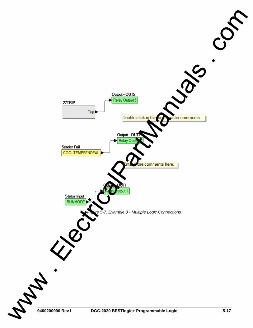
9400200990 Rev I DGC-2020 BESTlogic+ Programmable Logic 5-17
Figure 5-7. Example 3 - Multiple Logic Connections
www . El
ectric
alPar
tMan
uals
. com

5-18 DGC-2020 BESTlogic+ Programmable 9400200990 Rev I
This page intentionally left blank.
www . El
ectric
alPar
tMan
uals
. com
9400200990 Rev I DGC-2020 Installation i
SECTION 6 • INSTALLATION TABLE OF CONTENTS
SECTION 6 • INSTALLATION .................................................................................................................. 6-1
GENERAL.............................................................................................................................................. 6-1 PRODUCT REGISTRATION ................................................................................................................. 6-1 HARDWARE .......................................................................................................................................... 6-1 MOUNTING............................................................................................................................................ 6-1 CONNECTIONS .................................................................................................................................... 6-3
Terminations....................................................................................................................................... 6-3 Connections for Typical Applications ................................................................................................. 6-7 Connections for Volvo Penta EDC III Applications........................................................................... 6-12 Connections with LSM-2020 and CEM-2020................................................................................... 6-17
INSTALLATION FOR CE SYSTEMS................................................................................................... 6-17 INSTALLATION IN A SALT FOG ENVIRONMENT............................................................................. 6-17
Figures Figure 6-1. Panel Cutting and Drilling Dimensions.................................................................................... 6-1 Figure 6-2. Overall Dimensions ................................................................................................................. 6-2 Figure 6-3. 3-Phase Wye Connections for Typical Applications ............................................................... 6-8 Figure 6-4. 3-Phase Delta Connections for Typical Applications .............................................................. 6-9 Figure 6-5. Single-Phase A-B Connections for Typical Applications ...................................................... 6-10 Figure 6-6. Single-Phase A-C Connections for Typical Applications ...................................................... 6-11 Figure 6-7. 3-Phase Wye Connections for Volvo Penta EDC III Applications ........................................ 6-13 Figure 6-8. 3-Phase Delta Connections for Volvo Penta EDC III Applications ....................................... 6-14 Figure 6-9. Single-Phase A-B Connections for Volvo Penta EDC III Applications.................................. 6-15 Figure 6-10. Single-Phase A-C Connections for Volvo Penta EDC III Applications ............................... 6-16 Figure 6-11. DGC-2020, LSM-2020, CEM-2020 CANBus Connections ................................................. 6-17
Tables Table 6-1. Operating Power Terminals ..................................................................................................... 6-3 Table 6-2. Generator Current Sensing Terminals ..................................................................................... 6-4 Table 6-3. Generator Voltage Sensing Terminals ..................................................................................... 6-4 Table 6-4. Bus Voltage Sensing Terminals ............................................................................................... 6-4 Table 6-5. Sender Input Terminals ............................................................................................................ 6-5 Table 6-6. Magnetic Pickup Input Terminals ............................................................................................. 6-5 Table 6-7. Contact Sensing Inputs ............................................................................................................ 6-5 Table 6-8. Programmable Output Contact Terminals................................................................................ 6-6 Table 6-9. RS-485 Communication Port Terminals................................................................................... 6-6 Table 6-10. CAN Interface Terminals........................................................................................................ 6-7 Table 6-11. RDP-110 Interface Terminals................................................................................................. 6-7
www . El
ectric
alPar
tMan
uals
. com

ii DGC-2020 Installation 9400200990 Rev I
This page intentionally left blank.
www . El
ectric
alPar
tMan
uals
. com

9400200990 Rev I DGC-2020 Installation 6-1
SECTION 6 • INSTALLATION GENERAL DGC-2020 controllers are delivered in sturdy cartons to prevent shipping damage. Upon receipt of a system, check the part number against the requisition and packing list for agreement. Inspect for damage, and if there is evidence of such, immediately file a claim with the carrier and notify the Basler Electric regional sales office, your sales representative, or a sales representative at Basler Electric, Highland, Illinois USA. If the device is not installed immediately, store it in the original shipping package in a moisture- and dust-free environment.
PRODUCT REGISTRATION Registering with Basler Electric enables you to receive important information updates on your product plus new product announcements. Register your product by directing your web browser to www.basler.com.
HARDWARE DGC-2020 controllers are packaged for mounting in any top-mount enclosure. The front panel is resistant to moisture, salt fog, humidity, dust, dirt, and chemical contaminants. DGC-2020 controllers are mounted using the four permanently attached 10-24 studs. The torque applied to the mounting hardware should not exceed 25 inch-pounds (2.8 newton meters).
MOUNTING Panel cutting and drilling dimensions are shown in Figure 6-1. The horizontal measurement of 10.75 inches has a tolerance of +0.01/-0.01 inches. The horizontal measurement of 10.25 inches has a tolerance of +0.04/-0 inches. The vertical measurement of 7.25 inches has a tolerance of +0.01/-0.01 inches. The vertical measurement of 6.75 inches has a tolerance of +0.04/-0. Overall dimensions are shown in Figure 6-2. All dimensions are shown in inches with millimeters in parenthesis.
Figure 6-1. Panel Cutting and Drilling Dimensions
www . El
ectric
alPar
tMan
uals
. com

6-2 DGC-2020 Installation 9400200990 Rev I
Figure 6-2. Overall Dimensions
www . El
ectric
alPar
tMan
uals
. com

9400200990 Rev I DGC-2020 Installation 6-3
CONNECTIONS DGC-2020 connections are dependent on the application. Incorrect wiring may result in damage to the controller.
Terminations All DGC-2020 terminals are located on the rear panel of the controller. There are three types of interface terminals: a mini-B USB socket, plug-in connectors with screw-down compression terminals, and quarter-inch, male, quick-connect terminals. Controllers equipped with the optional, internal dial-out modem have an additional RJ-11 jack. The mini-B USB socket mates with a standard USB cable and provides local communication between the DGC-2020 and a PC running BESTCOMSPlus software. The majority of DGC-2020 connections are made with 15-position connectors with screw-down compression terminals. These connectors plug into headers on the DGC-2020. The connectors and headers have a dovetailed edge that ensures proper connector orientation. Each connector and header is uniquely keyed to ensure that a connector mates only with the correct header. Connector screw terminals accept a maximum wire size of 12 AWG. Maximum screw torque is 4 inch-pounds (0.45 N•m). Connections to the DGC-2020 starter, fuel solenoid, and glow plug output contacts are made directly to each relay through quarter-inch, male, quick-connect terminals. Amp part numbers 154718-3 (positive-lock receptacle) and 154719-1 (nylon housing) are the recommended components for making connections at these terminals. DGC-2020 terminal groups are described in the following paragraphs.
Operating Power The DGC-2020 operating power input accepts either 12 Vdc or 24 Vdc and tolerates voltage over the range of 6 to 32 Vdc. Operating power must be of the correct polarity. Although reverse polarity will not cause damage, the DGC-2020 will not operate. Operating power terminals are listed in Table 6-1. It is recommended that a fuse be added for additional protection for the wiring to the battery input of the DGC-2020. A Bussmann ABC-7 fuse or equivalent will help prevent wire damage and nuisance trips due to initial power supply inrush current.
Table 6-1. Operating Power Terminals
Terminal Description 1 (CHASSIS) Chassis ground connection 2 (BATT–) Negative side of operating power input 3 (BATT+) Positive side of operating power input
Generator Current Sensing The DGC-2020 has sensing inputs for A-phase, B-phase, and C-phase generator current. Depending on the style number, a DGC-2020 will have a nominal sensing current rating of 1 Aac or 5 Aac. A style number of 1xxxxxxxx indicates 1 Aac nominal current sensing and a style number of 5xxxxxxxx indicates 5 Aac nominal current sensing. Generator current sensing terminals are listed in Table 6-2.
NOTE Be sure that the DGC-2020 is hard-wired to earth ground with no smaller than 12 AWG copper wire attached to the chassis ground terminal (terminal 1) on the rear of the controller. Operating power from the battery must be of the correct polarity. Although reverse polarity will not cause damage, the DGC-2020 will not operate.
www . El
ectric
alPar
tMan
uals
. com

6-4 DGC-2020 Installation 9400200990 Rev I
Table 6-2. Generator Current Sensing Terminals
Terminal Description 68 (IA–) 69 (IA+)
A-phase current sensing input
71 (IB–) 72 (IB+)
B-phase current sensing input
74 (IC–) 75 (IC+)
C-phase current sensing input
Generator Voltage Sensing The DGC-2020 accepts either line-to-line or line-to-neutral generator sensing voltage over the range of 12 to 576 volts, rms line-to-line. Depending on the style number, a DGC-2020 will have a nominal generator frequency rating of 50/60 hertz or 400 hertz. A style number of x1xxxxxxxx indicates 50/60 hertz generator voltage and a style number of x2xxxxxxxx indicates 400-hertz generator voltage. Generator voltage sensing terminals are listed in Table 6-3.
Table 6-3. Generator Voltage Sensing Terminals
Terminal Description 35 (GEN VN) Neutral generator voltage sensing input 37 (GEN VC) C-phase generator voltage sensing input 39 (GEN VB) B-phase generator voltage sensing input 41 (GEN VA) A-phase generator voltage sensing input
Bus Voltage Sensing Sensing of bus voltage enables the DGC-2020 to detect failures of the mains (utility). Controllers with style number xxxxxxxAx use bus voltage sensing to perform automatic synchronization of the generator with the bus (style number xxxxxxxAx only). The DGC-2020 senses A-phase and B-phase bus voltage. Bus voltage sensing terminals are listed in Table 6-4.
Table 6-4. Bus Voltage Sensing Terminals
Terminal Description 43 (BUS VB) B-phase bus voltage sensing input 45 (BUS VA) A-phase bus voltage sensing input
Analog Engine Sender Inputs Inputs are provided for oil pressure, fuel level, and coolant temperature senders. Oil pressure senders that are compatible with the DGC-2020 include Datacon 02505-00, Isspro model R8919, and Stewart-Warner models 279BF, 279C, 411K, and 411M. Other senders may be used. Compatible fuel level senders include Isspro model R8925. Other senders may be used. Coolant temperature senders that are compatible with the DGC-2020 include Datacon 02019-00, Faria TS4042, Isspro model R8959 and Stewart-Warner model 334-P. Other senders may be used. Sender input terminals are listed in Table 6-5.
NOTE Unused current sensing inputs should be shorted to minimize noise pickup.
www . El
ectric
alPar
tMan
uals
. com

9400200990 Rev I DGC-2020 Installation 6-5
Table 6-5. Sender Input Terminals
Terminal Description 8 (OIL) Oil pressure sender input 9 (FUEL) Fuel level sender input 10 (COOLANT) Coolant temperature sender input 11 (SENDER COM) Sender return terminal
Magnetic Pickup Input The magnetic pickup input accepts a speed signal over the range of 3 to 35 volts, peak and 32 to 10,000 hertz. Magnetic pickup input terminals are listed in Table 6-6.
Table 6-6. Magnetic Pickup Input Terminals
Terminal Description 31 (MPU+) Magnetic pickup positive input 32 (MPU–) Magnetic pickup return input
Contact Sensing Inputs Contact sensing inputs consist of 1 emergency stop input and 16 programmable inputs. The emergency stop input is intended for use with a normally closed switch and recognizes an emergency stop input when the short-circuit across the input is removed. The programmable inputs accept normally open, dry contacts. Terminal 2 (BATT–) serves as the common return line for the programmable inputs. Information about configuring the programmable inputs is provided in Section 4, BESTCOMSPlus Software. Contact sensing input terminals are listed in Table 6-7.
Table 6-7. Contact Sensing Inputs
Terminal Description 2 (BATT–) Common return line for programmable contact inputs 15 (INPUT 16) Programmable contact input 16 16 (INPUT 15) Programmable contact input 15 17 (INPUT 14) Programmable contact input 14 18 (INPUT 13) Programmable contact input 13 19 (INPUT 12) Programmable contact input 12 20 (INPUT 11) Programmable contact input 11 21 (INPUT 10) Programmable contact input 10 22 (INPUT 9) Programmable contact input 9 23 (INPUT 8) Programmable contact input 8 24 (INPUT 7) Programmable contact input 7 25 (INPUT 6) Programmable contact input 6 26 (INPUT 5) Programmable contact input 5 27 (INPUT 4) Programmable contact input 4 28 (INPUT 3) Programmable contact input 3 29 (INPUT 2) Programmable contact input 2 30 (INPUT 1) Programmable contact input 1 46 (ESTOP) 47 (ESTOP)
Emergency stop contact input
www . El
ectric
alPar
tMan
uals
. com

6-6 DGC-2020 Installation 9400200990 Rev I
Output Contacts The DGC-2020 has three sets of fixed-function output contacts: Pre, Start, and Run. The Pre contacts supply battery power to the engine glow plugs, the Start contacts supply power to the start solenoid, and the Run contacts supply power to the fuel solenoid. Connections to the three sets of contacts are made directly at each relay using female, quarter-inch, quick-connect terminals. Amp part numbers 154718-3 (positive-lock receptacle) and 154719-1 (nylon housing) are the recommended components for making connections at each relay. For the location of the Pre, Start, and Run relays refer to Figure 2-2. Depending on the style number of the DGC-2020, either 4 or 12 sets of programmable output contacts are provided. Four programmable outputs are provided on DGC-2020 controllers with a style number of xxAxxxxxx. Twelve programmable outputs are provided on controllers with a style number of xxBxxxxxx. Programmable output contact terminals are listed in Table 6-8.
Table 6-8. Programmable Output Contact Terminals
Terminal Description 51 (COM 1, 2, 3) Common connection for outputs 1, 2, and 3 52 (OUT 1) Programmable output 1 53 (OUT 2) Programmable output 2 54 (OUT 3) Programmable output 3 55 (COM 4, 5, 6) Common connection for outputs 4, 5, and 6 56 (OUT 4) Programmable output 4 57 (OUT 5) Programmable output 5 58 (OUT 6) Programmable output 6 59 (COM 7, 8, 9) Common connection for outputs 7, 8, and 9 60 (OUT 7) Programmable output 7 61 (OUT 8) Programmable output 8 62 (OUT 9) Programmable output 9 63 (COM 10, 11, 12) Common connection for outputs 10, 11, and 12 64 (OUT 10) Programmable output 10 65 (OUT 11) Programmable output 11 66 (OUT 12) Programmable output 12
USB Interface A mini-B USB socket enables local communication with a PC running BESTCOMSPlus software. The DGC-2020 is connected to a PC using a standard USB cable equipped with a type A plug on one end (PC termination) and a mini-B plug on the other end (DGC-2020 termination).
RS-485 Communication Port DGC-2020 controllers with the optional RS-485 communication port (style number xxxRxxxxx) are equipped for polled communication over a Modbus™ network. Twisted-pair, shielded cable is recommended for RS-485 port connections. RS-485 communication port terminals are listed in Table 6-9.
Table 6-9. RS-485 Communication Port Terminals
Terminal Description 12 (485 SHIELD) Shield connection for RS-485 cable 13 (485B) RS-485 send/receive B connection 14 (485A) RS-485 send/receive A connection
www . El
ectric
alPar
tMan
uals
. com
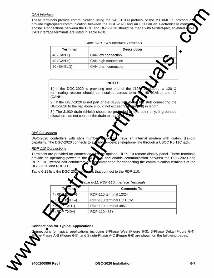
9400200990 Rev I DGC-2020 Installation 6-7
CAN Interface These terminals provide communication using the SAE J1939 protocol or the MTU/MDEC protocol and provide high-speed communication between the DGC-2020 and an ECU on an electronically controlled engine. Connections between the ECU and DGC-2020 should be made with twisted-pair, shielded cable. CAN interface terminals are listed in Table 6-10.
Table 6-10. CAN Interface Terminals
Terminal Description 48 (CAN L) CAN low connection 49 (CAN H) CAN high connection 50 (SHIELD) CAN drain connection
Dial-Out Modem DGC-2020 controllers with style number xxxxxMxxx have an internal modem with dial-in, dial-out capability. The DGC-2020 connects to a standard-device telephone line through a USOC RJ-11C jack.
RDP-110 Connections Terminals are provided for connection with the optional RDP-110 remote display panel. These terminals provide dc operating power to the RDP-110 and enable communication between the DGC-2020 and RDP-110. Twisted-pair conductors are recommended for connecting the communication terminals of the DGC-2020 and RDP-110. Table 6-11 lists the DGC-2020 terminals that connect to the RDP-110.
Table 6-11. RDP-110 Interface Terminals
Terminal Connects To: 4 (RDP BATT+) RDP-110 terminal 12/24 5 (RDP BATT–) RDP-110 terminal DC COM 6 (RDP TXD–) RDP-110 terminal 485– 7 (RDP TXD+) RDP-110 485+
Connections for Typical Applications Connections for typical applications including 3-Phase Wye (Figure 6-3), 3-Phase Delta (Figure 6-4), Single-Phase A-B (Figure 6-5), and Single-Phase A-C (Figure 6-6) are shown on the following pages.
NOTES 1.) If the DGC-2020 is providing one end of the J1939 backbone, a 120 Ω terminating resistor should be installed across terminals 48 (CANL) and 49 (CANH). 2.) If the DGC-2020 is not part of the J1939 backbone, the stub connecting the DGC-2020 to the backbone should not exceed 914 mm (3 ft) in length. 3.) The J1939 drain (shield) should be grounded at one point only. If grounded elsewhere, do not connect the drain to the DGC-2020.
www . El
ectric
alPar
tMan
uals
. com
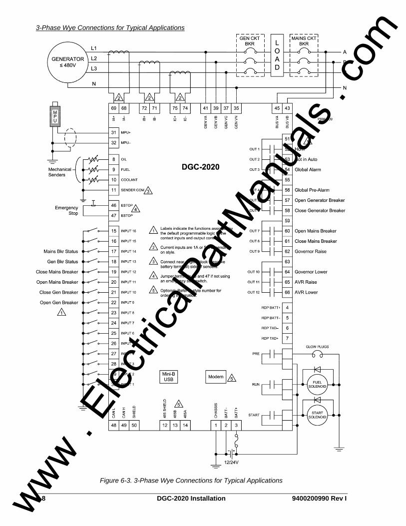
6-8 DGC-2020 Installation 9400200990 Rev I
3-Phase Wye Connections for Typical Applications
Figure 6-3. 3-Phase Wye Connections for Typical Applications
www . El
ectric
alPar
tMan
uals
. com

9400200990 Rev I DGC-2020 Installation 6-9
3-Phase Delta Connections for Typical Applications
Figure 6-4. 3-Phase Delta Connections for Typical Applications
www . El
ectric
alPar
tMan
uals
. com

6-10 DGC-2020 Installation 9400200990 Rev I
Single-Phase A-B Connections for Typical Applications
Figure 6-5. Single-Phase A-B Connections for Typical Applications
www . El
ectric
alPar
tMan
uals
. com

9400200990 Rev I DGC-2020 Installation 6-11
Single-Phase A-C Connections for Typical Applications
Figure 6-6. Single-Phase A-C Connections for Typical Applications
www . El
ectric
alPar
tMan
uals
. com

6-12 DGC-2020 Installation 9400200990 Rev I
Connections for Volvo Penta EDC III Applications Engines equipped with Volvo Penta EDC III controllers can receive engine control commands (such as start and stop) from the DGC-2020 through the SAE J1939 communication interface. To invoke this feature, the EDC III must receive a J1939 message containing engine control information within one second of waking (exiting sleep mode). If the EDC III does not receive an engine control message within the prescribed time, it will enter the stand-alone mode and ignore any J1939 control messages. If this occurs, the EDC III must be forced back into sleep mode by pressing the auxiliary stop pushbutton on the engine or by momentarily disconnecting EDC power. The interconnection diagrams of Figures 6-7 through 6-10 illustrate the DGC-2020 and EDC III connections that allow the DGC-2020 to awaken the EDC III and start the engine, or simply acquire engine status information. Wake-up of the EDC III is initiated by using the DGC-2020 RUN output contacts to apply battery power to the EDC. To stop the engine, the DGC-2020 sends a sleep command through the J1939 interface to the EDC III and opens the RUN output contacts. This causes the EDC to stop the engine and enter the sleep mode. In order for the DGC-2020 to communicate with the EDC III, two DGC-2020 settings must be changed from their default values. • The J1939 address of the DGC-2020 must be set at 17. • The engine start/stop configuration setting must be set for Volvo Penta.
Both settings are configured on the CANBus Setup screen of BESTCOMSPlus. Section 4, BESTCOMSPlus Software has information about adjusting DGC-2020 settings through BESTCOMSPlus.
www . El
ectric
alPar
tMan
uals
. com

9400200990 Rev I DGC-2020 Installation 6-13
3-Phase Wye Connections for Volvo Penta EDC III Applications
Figure 6-7. 3-Phase Wye Connections for Volvo Penta EDC III Applications
www . El
ectric
alPar
tMan
uals
. com

6-14 DGC-2020 Installation 9400200990 Rev I
3-Phase Delta Connections for Volvo Penta EDC III Applications
Figure 6-8. 3-Phase Delta Connections for Volvo Penta EDC III Applications
www . El
ectric
alPar
tMan
uals
. com
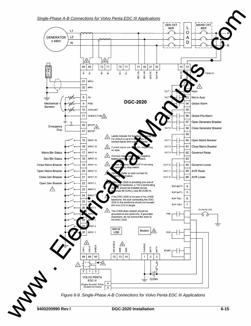
9400200990 Rev I DGC-2020 Installation 6-15
Single-Phase A-B Connections for Volvo Penta EDC III Applications
Figure 6-9. Single-Phase A-B Connections for Volvo Penta EDC III Applications
www . El
ectric
alPar
tMan
uals
. com

6-16 DGC-2020 Installation 9400200990 Rev I
Single-Phase A-C Connections for Volvo Penta EDC III Applications
Figure 6-10. Single-Phase A-C Connections for Volvo Penta EDC III Applications
www . El
ectric
alPar
tMan
uals
. com

9400200990 Rev I DGC-2020 Installation 6-17
Connections with LSM-2020 and CEM-2020 The LSM-2020 (Load Share Module) and CEM-2020 (Contact Expansion Module) are optional modules that may be installed with the DGC-2020. These modules interface to the DGC-2020 via CANBus, thus the CANBUS terminals are the only common connections (Figure 6-11) between the DGC-2020, LSM-2020, and CEM-2020. Refer to Section 8, LSM-2020 (Load Share Module), for independent LSM-2020 connections. Refer to Section 9, CEM-2020 (Contact Expansion Module), for independent CEM-2020 connections. Refer to Connections, CAN Interface, in this section for details on DGC-2020 CANBus connections.
101112
LSM-2020CANL
CANH
GND
P0053-21
154
CEM-2020CANL
CANH
GND
504948
DGC-2020CANL
CANH
GND
CANH
CANL
GND/SHIELD
Figure 6-11. DGC-2020, LSM-2020, CEM-2020 CANBus Connections
INSTALLATION FOR CE SYSTEMS For CE compliant systems, it may be required to route ac voltage and current sensing wires separately from other wires.
INSTALLATION IN A SALT FOG ENVIRONMENT If the DGC-2020 will be installed in a salt-fog environment, it is recommended that the backup battery for the real-time clock be removed. Salt fog is known to be conductive and may short-circuit the battery. Information on removing the backup battery for the real-time clock can be found in Section 7, Maintenance and Troubleshooting.
www . El
ectric
alPar
tMan
uals
. com

6-18 DGC-2020 Installation 9400200990 Rev I
This page intentionally left blank.
www . El
ectric
alPar
tMan
uals
. com

9400200990 Rev I DGC-2020 Maintenance and Troubleshooting i
SECTION 7 • MAINTENANCE AND TROUBLESHOOTING
TABLE OF CONTENTS SECTION 7 • MAINTENANCE AND TROUBLESHOOTING.................................................................... 7-1
MAINTENANCE..................................................................................................................................... 7-1 Backup Battery for the Real Time Clock ............................................................................................ 7-1
TROUBLESHOOTING........................................................................................................................... 7-1 Incorrect Display of Battery Voltage, Coolant Temperature, Oil Pressure, or Fuel Level.................. 7-1 Incorrect Display of Generator Voltage .............................................................................................. 7-2 Incorrect Measurement or Display of Generator Current................................................................... 7-2 Incorrect Display of Engine RPM ....................................................................................................... 7-2 Programmable Inputs Do Not Operate as Expected.......................................................................... 7-2 Programmable Outputs Do Not Operate as Expected....................................................................... 7-2 Communication Port Does Not Operate Properly .............................................................................. 7-2
www . El
ectric
alPar
tMan
uals
. com

ii DGC-2020 Maintenance and Troubleshooting 9400200990 Rev I
This page intentionally left blank.
www . El
ectric
alPar
tMan
uals
. com

9400200990 Rev I DGC-2020 Maintenance and Troubleshooting 7-1
SECTION 7 • MAINTENANCE AND TROUBLESHOOTING
MAINTENANCE Preventative maintenance consists of periodic replacement of the backup battery (optional) and periodically checking that the connections between the DGC-2020 and the system are clean and tight. DGC-2020 units are manufactured using state-of-the-art, surface-mount technology. As such, Basler Electric recommends that no repair procedures be attempted by anyone other than Basler Electric personnel.
Backup Battery for the Real Time Clock The backup battery for the real time clock is an option available for the DGC-2020 Digital Genset Controller. A 3.0 Vdc, 190-mAh lithium battery (type Rayovac BR2032) is used to maintain clock function during loss of power supply voltage. In mobile substation and generator applications, the primary battery system that supplies the DGC-2020 power supply may be disconnected for extended periods (weeks, months) between uses. Without battery backup for the real time clock, clock functions will cease if battery input power is removed. The backup battery has a life expectancy of approximately 10 years. After this time, you should contact Basler Electric to order a new battery, Basler Electric P/N 38526. Battery access is located on the rear side of the DGC-2020.
TROUBLESHOOTING If you do not get the results that you expect from the DGC-2020, first check the programmable settings for the appropriate function. Use the following troubleshooting procedures when difficulties are encountered in the operation of your genset control system.
Incorrect Display of Battery Voltage, Coolant Temperature, Oil Pressure, or Fuel Level Step 1. Verify that all wiring is properly connected. Refer to Figures 6-3 through 6-10. Step 2. Confirm that the SENDER COM terminal (11) is connected to the negative battery terminal and
the engine-block side of the senders. Current from other devices sharing this connection can cause erroneous readings.
Step 3. If the displayed battery voltage is incorrect, ensure that the proper voltage is present between the BATT+ terminal (3) and the SENDER COM terminal (11).
Step 4. Verify that the correct senders are being used.
CAUTION Replacement of the backup battery for the real-time clock should be performed only by qualified personnel. Do not short-circuit the battery, reverse battery polarity, or attempt to recharge the battery. Observe polarity markings on the battery socket while inserting a new battery. The battery polarity must be correct in order to provide backup for the real-time clock. It is recommended that the battery be removed if the DGC-2020 is to be operated in a salt-fog environment. Salt fog is known to be conductive and may short-circuit the battery.
NOTE Failure to replace the battery with Basler Electric P/N 38526 may void the warranty.
www . El
ectric
alPar
tMan
uals
. com

7-2 DGC-2020 Maintenance and Troubleshooting 9400200990 Rev I
Step 5. Verify that the correct sender curves are being used. Step 6. Ensure that the senders are operating properly.
Incorrect Display of Generator Voltage Step 1. Verify that all wiring is properly connected. Refer to Figures 6-3 through 6-10. Step 2. Ensure that the proper voltage is present at the DGC-2020 voltage sensing inputs (41, 39, 37,
and 35). Step 3. Verify that the voltage transformer ratio and sensing configuration is correct. Step 4. Confirm that the voltage sensing transformers are correct and properly installed.
Incorrect Measurement or Display of Generator Current Step 1. Verify that all wiring is properly connected. Refer to Figures 6-3 through 6-10. Step 2. Ensure that the proper current is present at the DGC-2020 current sensing inputs (68/69,
71/72, and 74/75. Step 3. Verify that the current sensing transformer ratios are correct. Step 4. Confirm that the current sensing transformers are correct and properly installed.
Incorrect Display of Engine RPM Step 1. Verify that all wiring is properly connected. Refer to Figures 6-3 through 6-10. Step 2. Verify that the flywheel teeth setting is correct. Step 3. Confirm the nominal frequency setting. Step 4. Verify that the prime mover governor is operating properly. Step 5. Verify that the measured frequency of the voltage at the MPU input (31 and 32) is correct. Step 6. If the MPU is shared with the governor, verify that the polarity of the MPU input to the governor
matches the polarity of the MPU input to the DGC-2020.
Programmable Inputs Do Not Operate as Expected Step 1. Verify that all wiring is properly connected. Refer to Figures 6-3 through 6-10. Step 2. Confirm that the inputs are programmed properly. Step 3. Ensure that the input at the DGC-2020 is actually connected to the BATT– terminal (2).
Programmable Outputs Do Not Operate as Expected Step 1. Verify that all wiring is properly connected. Refer to Figures 6-3 through 6-10. Step 2. Confirm that the outputs are programmed properly.
Communication Port Does Not Operate Properly Step 1. Verify that the proper port of your computer is being used. For more information, refer to
Section 4, BESTCOMSPlus Software, Communication.
www . El
ectric
alPar
tMan
uals
. com

9400200990 Rev I DGC-2020 LSM-2020 (Load Share Module) i
SECTION 8 • LSM-2020 (LOAD SHARE MODULE) TABLE OF CONTENTS
SECTION 8 • LSM-2020 (LOAD SHARE MODULE) ................................................................................ 8-1
GENERAL INFORMATION.................................................................................................................... 8-1 FEATURES............................................................................................................................................ 8-1 SPECIFICATIONS ................................................................................................................................. 8-1
Operating Power ................................................................................................................................ 8-1 Analog Outputs................................................................................................................................... 8-1 Communication Interface ................................................................................................................... 8-1 Type Tests.......................................................................................................................................... 8-2 Environment ....................................................................................................................................... 8-2 UL/CSA Approvals ............................................................................................................................. 8-2 NFPA Compliance.............................................................................................................................. 8-2 CE Compliance .................................................................................................................................. 8-2 Physical .............................................................................................................................................. 8-2
FUNCTIONAL DESCRIPTION .............................................................................................................. 8-3 Load Share Overview......................................................................................................................... 8-3 Analog Outputs................................................................................................................................... 8-3 Generator Sequencing ....................................................................................................................... 8-3 Communications................................................................................................................................. 8-3
BESTCOMSPlus SOFTWARE .............................................................................................................. 8-4 LSM-2020 Plugin for BESTCOMSPlus .............................................................................................. 8-4
INSTALLATION...................................................................................................................................... 8-5 Product Registration........................................................................................................................... 8-5 Mounting............................................................................................................................................. 8-5 Connections........................................................................................................................................ 8-6 Connections for Typical Applications ................................................................................................. 8-9 Connections using AVR’, GOV’, and LS’ ......................................................................................... 8-10
MAINTENANCE................................................................................................................................... 8-10
Figures Figure 8-1. Device Info Screen.................................................................................................................. 8-4 Figure 8-2. Device Security Setup Screen ................................................................................................ 8-5 Figure 8-3. LSM-2020 Overall Dimensions ............................................................................................... 8-6 Figure 8-4. CANBus Interface with LSM-2020 providing One End of the Backbone ................................ 8-8 Figure 8-5. CANBus Interface with DGC-2020 providing One End of the Backbone ............................... 8-9 Figure 8-6. Typical LSM-2020 Connections .............................................................................................. 8-9 Figure 8-7. Connections using the AVR’ Terminal .................................................................................. 8-10
Tables Table 8-1. Operating Power Terminals ..................................................................................................... 8-7 Table 8-2. Analog Output Terminals ......................................................................................................... 8-7 Table 8-3. Analog Input Terminals ............................................................................................................ 8-7 Table 8-4. CAN Interface Terminals.......................................................................................................... 8-8
www . El
ectric
alPar
tMan
uals
. com

ii DGC-2020 LSM-2020 (Load Share Module) 9400200990 Rev I
This page intentionally left blank.
www . El
ectric
alPar
tMan
uals
. com

9400200990 Rev I DGC-2020 LSM-2020 (Load Share Module) 8-1
SECTION 8 • LSM-2020 (LOAD SHARE MODULE) GENERAL INFORMATION The LSM-2020 is a remote auxiliary device that interfaces to the DGC-2020 and provides analog outputs to the power system in the form of analog bias signals to the voltage regulator and speed governor. When the breaker is closed and Load Sharing is enabled, the LSM-2020 will share real power load proportionally with the other generators on the Analog Load Share Line.
FEATURES LSM-2020’s have the following features: • A Ramping Function to load and unload generators smoothly • Communications via Ethernet, CANBUS, or USB • Demand Start/Stop and Generator Sequencing • KW Load Control • KW Load Sharing via analog load share lines
SPECIFICATIONS
Operating Power Nominal: 12 or 24 Vdc Range: 8 to 32 Vdc (Withstands cranking ride-through down to 6 Vdc
for 500 ms.) Terminals: P2-3 (–), P2-2 (+), P2-1 (chassis ground)
Analog Outputs Burden Data: 4-20 mA = 500Ω maximum burden, ±10 Vdc = 667Ω minimum burden
Voltage Regulator Bias Output 4-20 mA or ±10 Vdc isolated output signal. (Selectable in increments of 0.1.) Isolated to 1,500 Vdc between outputs and ground Terminals: P2-18 (AVR+), P2-17 (AVR–), P2-16 (AVR’)
Governor Bias Output 4-20 mA, ±10 Vdc isolated output signal. (Selectable in increments of 0.1.) Isolated to 500 Vdc between outputs and ground Terminals: P2-15 (GOV+), P2-14 (GOV–), P2-13 (GOV’)
Load Share Line Output 0-10 Vdc isolated output signal. (Selectable in increments of 0.1 Vdc. Isolated to 500 Vdc between outputs and ground Terminals: P2-6 (LS+), P2-5 (LS–), P2-4 (LS’)
Communication Interface
CANBus Differential Bus Voltage: 1.5 to 3 Vdc Maximum Voltage: –32 to +32 Vdc with respect to negative battery terminal Communication Rate: 250 kb/s Terminals: P2-12 (low), P2-11 (high), and P2-10 (shield)
Ethernet Rear-panel RJ-45 connector provides remote communications via BESTCOMSPlus to the LSM-2020 and to the DGC-2020 that the module is connected to. Type: 10/100BASE-T
www . El
ectric
alPar
tMan
uals
. com

8-2 DGC-2020 LSM-2020 (Load Share Module) 9400200990 Rev I
Type Tests
Shock 15 G in 3 perpendicular planes
Vibration Swept over the following ranges for 12 sweeps in each of three mutually perpendicular planes with each 15-minute sweep consisting of the following: 5 to 29 to 5 Hz: 1.5 G peak for 5 min. 29 to 52 to 29 Hz: 0.036” Double Amplitude for 2.5 min. 52 to 500 to 52 Hz: 5 G peak for 7.5 min.
Ignition System Tested in closed proximity to an unshielded, unsuppressed Altronic DISN 800 ignition system.
HALT (Highly Accelerated Life Testing) HALT is used by many manufacturers to prove that their products will provide the user with many years of reliable service. HALT subjects the device to extremes in temperature, shock, and vibration to simulate years of operation, but in a much shorter period span. HALT allows Basler Electric to evaluate all possible design elements that will add to the life of this device. As an example of some of the extreme testing conditions, the LSM-2020 was subjected to temperature tests (tested over a temperature range of -80°C to +130°C), vibration tests (of 5 to 50 G at +25°C), and temperature/vibration tests (tested at 10 to 20 G over a temperature range of -60°C to +100°C). Combined temperature and vibration testing at these extremes proves that the LSM-2020 is expected to provide long-term operation in a rugged environment. Note that the vibration and temperature extremes listed in this paragraph are specific to HALT and do not reflect recommended operation levels. These operational ratings are included in Section 8 of this manual.
Environment Temperature Operating: –40 to 70°C (–40 to 158°F) Storage: –40 to 85°C (–40 to 185°F) Humidity: IEC 68-2-38
UL/CSA Approvals “cURus” recognized to UL 508 and CSA C22.2 No.14 “cURus” recognized per Standard 1604, Electrical Equipment for Use in Class I and II, Division 2, and Class III Hazardous (Classified) Locations, Class I, Division 2, Zone 2, Groups A, B, C, D, Temperature Code - T4.
NFPA Compliance Complies with NFPA Standard 110, Standard for Emergency and Standby Power.
CE Compliance This product complies with the requirements of the following EC Directives: • Low Voltage Directive (LVD) - 73/23/EEC as amended by 93/68/EEC • Electromagnetic Compatibility (EMC) - 89/336/EEC as amended by 92/31/EEC and 93/68/EEC
This product conforms to the following Harmonized Standards: • EN 50178:1997 - Electronic Equipment for use in Power Installations • EN 61000-6-4:2001 - Electromagnetic Compatibility (EMC), Generic Standards, Emission Standard
for Industrial Environments • EN 61000-6-2:2001 - Electromagnetic Compatibility (EMC), Generic Standards, Immunity for
Industrial Environments
Physical Weight: 0.66 kg (1.45 lb) Dimensions: See Installation later in this section.
www . El
ectric
alPar
tMan
uals
. com

9400200990 Rev I DGC-2020 LSM-2020 (Load Share Module) 8-3
FUNCTIONAL DESCRIPTION
Load Share Overview A generator is paralleled with other generators on an island system, which is not connected to the utility. The generator shares load with other generators on the system via the load share line. The load share line of a generator is driven in proportion to the per unitized kW generation of the generator. The voltage at the junction of all load share lines is proportional to the per unitized average power generation of the system. For example, if the load share line operating voltage is 0 to 3 volts, and the measured voltage at the intersection point is 2 volts, the system is at 2/3 of its kW capacity. The generator uses the measured load share line input value to calculate per unitized average load level, and uses that as the setpoint for its kW controller. A generator has a set of contacts that physically disconnects it from the load share line circuit. These contacts are open whenever the unit’s generator breaker is open. If a unit or set of units is paralleled to the utility, they derive their setting from the Mains Parallel Power Level setting, and disregard the load share line input. Settings are provided to allow a generator to make a bumpless transition onto the system that is participating in load sharing. A bumpless transition is also achieved when the generator is brought offline.
Analog Outputs There are three analog outputs: AVR control, GOV control, and Load Share Line. Each output is described in the following paragraphs.
Output for Voltage Regulator Control The AVR output provides remote control of the generator voltage setpoint
Output for Governor Control The GOV output provides remote control of the generator speed setpoint.
Load Share Line Output The generator uses the measured LS (Load Share Line) output to calculate per unitized average load level, and uses that as the set point for its kW controller.
Generator Sequencing Machines can be added or removed from the power system based on load demand. The following criteria should be considered before adding or removing a machine: • Machine Priority • Engine Run Time • Machine Size • kW% of the load/demand • Out of Service machines
Communications The LSM-2020 communication ports include CAN terminals and an ethernet port.
CANBus A Control Area Network (CAN) is a standard interface that enables communication between the LSM-2020 and the DGC-2020.
Ethernet Port An ethernet port provides communications via BESTCOMSPlus to the LSM-2020 and to the DGC-2020 that the module is connected to. Ethernet communication between LSM-2020s allows for generator sequencing on an islanded system. Firmware updates to the LSM-2020 are made through the ethernet port. Firmware updates to the DGC-2020 are only available through the USB port of the DGC-2020. Refer to Section 4, BESTCOMSPlus, for information on updating firmware in the DGC-2020.
www . El
ectric
alPar
tMan
uals
. com
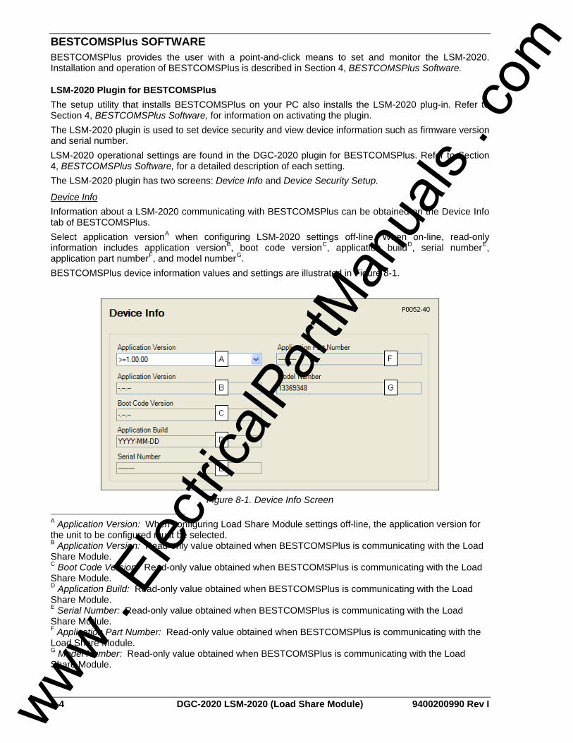
8-4 DGC-2020 LSM-2020 (Load Share Module) 9400200990 Rev I
BESTCOMSPlus SOFTWARE BESTCOMSPlus provides the user with a point-and-click means to set and monitor the LSM-2020. Installation and operation of BESTCOMSPlus is described in Section 4, BESTCOMSPlus Software.
LSM-2020 Plugin for BESTCOMSPlus The setup utility that installs BESTCOMSPlus on your PC also installs the LSM-2020 plug-in. Refer to Section 4, BESTCOMSPlus Software, for information on activating the plugin. The LSM-2020 plugin is used to set device security and view device information such as firmware version and serial number. LSM-2020 operational settings are found in the DGC-2020 plugin for BESTCOMSPlus. Refer to Section 4, BESTCOMSPlus Software, for a detailed description of each setting. The LSM-2020 plugin has two screens: Device Info and Device Security Setup.
Device Info Information about a LSM-2020 communicating with BESTCOMSPlus can be obtained on the Device Info tab of BESTCOMSPlus. Select application versionA when configuring LSM-2020 settings off-line. When on-line, read-only information includes application versionB, boot code versionC, application buildD, serial numberE, application part numberF, and model numberG. BESTCOMSPlus device information values and settings are illustrated in Figure 8-1.
Figure 8-1. Device Info Screen
A Application Version: When configuring Load Share Module settings off-line, the application version for the unit to be configured must be selected. B Application Version: Read-only value obtained when BESTCOMSPlus is communicating with the Load Share Module. C Boot Code Version: Read-only value obtained when BESTCOMSPlus is communicating with the Load Share Module. D Application Build: Read-only value obtained when BESTCOMSPlus is communicating with the Load Share Module. E Serial Number: Read-only value obtained when BESTCOMSPlus is communicating with the Load Share Module. F Application Part Number: Read-only value obtained when BESTCOMSPlus is communicating with the Load Share Module. G Model Number: Read-only value obtained when BESTCOMSPlus is communicating with the Load Share Module.
www . El
ectric
alPar
tMan
uals
. com

9400200990 Rev I DGC-2020 LSM-2020 (Load Share Module) 8-5
Device Security Setup Password protection guards against unauthorized changing of LSM-2020 communication settings. Passwords are case sensitive. OEM Access is the only level of password protection available. This password level allows access to all settings made using the LSM-2020 plugin for BESTCOMSPlus. The default, OEM-access password is OEM. Passwords can be changed only after communication between the PC and LSM-2020 is established. A change to the password is made through the Device Security Setup screen. Use the Settings Explorer in BESTCOMSPlus to open the General Settings, Device Security Setup screen. See Figure 8-2. A password is changed by clicking on the access levelA, entering the new passwordB, and then clicking on the Save Password buttonC.
Figure 8-2. Device Security Setup Screen
A Access Level/Password: Read-only value obtained when BESTCOMSPlus is communicating with the Load Share Module. B Password: Accepts an alphanumeric character string of up to 16 characters. C Save Password: Clicking this button will save the password changes in BESTCOMSPlus memory.
INSTALLATION LSM-2020’s are delivered in sturdy cartons to prevent shipping damage. Upon receipt of a module, check the part number against the requisition and packing list for agreement. Inspect for damage, and if there is evidence of such, immediately file a claim with the carrier and notify the Basler Electric regional sales office, your sales representative, or a sales representative at Basler Electric, Highland, Illinois USA. If the device is not installed immediately, store it in the original shipping package in a moisture- and dust-free environment.
Product Registration Registering with Basler Electric enables you to receive important information updates on your product plus new product announcements. Register your product by directing your web browser to www.basler.com.
Mounting LSM-2020’s are contained in an encapsulated plastic case and may be mounted in any convenient position. The construction of a LSM-2020 is durable enough to mount directly on a genset using UNF ¼-20 or equivalent hardware. Hardware selection should be based on any expected shipping/transportation and operating conditions. The torque applied to the mounting hardware should not exceed 65 in-lb (7.34 N•m). See Figure 8-3 for LSM-2020 overall dimensions. All dimensions are shown in inches with millimeters in parenthesis.
www . El
ectric
alPar
tMan
uals
. com

8-6 DGC-2020 LSM-2020 (Load Share Module) 9400200990 Rev I
5.50 [139.7]
15
16
17
18
6.38 [162.0]
7.50 [190.5] 8.38 [212.8]
1.39 [35.3]
1
2
3
4
5
6
7
8
9
10
11
12
13
14
P0052-36
P2J3
Figure 8-3. LSM-2020 Overall Dimensions
Connections LSM-2020 connections are dependent on the application. Incorrect wiring may result in damage to the module.
Terminations There are two types of interface terminals: plug-in connectors with screw-down compression terminals and an RJ-45 socket. The RJ-45 socket mates with a standard ethernet cable and provides local communication between the LSM-2020 and a PC running BESTCOMSPlus software. This allows for setting of the LSM-2020 and for the DGC-2020 that the module is connected to. LSM-2020 connections are made with an 18-position connector with screw-down compression terminals. This connector plugs into a header on the LSM-2020. The connector and header have a dovetailed edge that ensures proper connector orientation. The connector and header are uniquely keyed to ensure that the connector mates only with the correct header. Connector screw terminals accept a maximum wire size of 12 AWG. Maximum screw torque is 4 inch-pounds (0.45 N•m).
NOTE Operating power from the battery must be of the correct polarity. Although reverse polarity will not cause damage, the LSM-2020 will not operate. Be sure that the LSM-2020 is hard-wired to earth ground with no smaller than 12 AWG copper wire attached to the chassis ground terminal (P2-1) on the module.
www . El
ectric
alPar
tMan
uals
. com
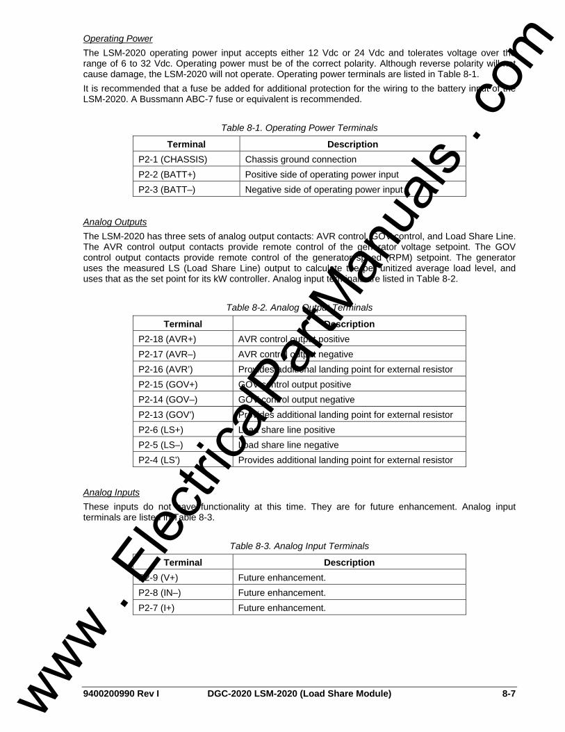
9400200990 Rev I DGC-2020 LSM-2020 (Load Share Module) 8-7
Operating Power The LSM-2020 operating power input accepts either 12 Vdc or 24 Vdc and tolerates voltage over the range of 6 to 32 Vdc. Operating power must be of the correct polarity. Although reverse polarity will not cause damage, the LSM-2020 will not operate. Operating power terminals are listed in Table 8-1. It is recommended that a fuse be added for additional protection for the wiring to the battery input of the LSM-2020. A Bussmann ABC-7 fuse or equivalent is recommended.
Table 8-1. Operating Power Terminals
Terminal Description P2-1 (CHASSIS) Chassis ground connection P2-2 (BATT+) Positive side of operating power input P2-3 (BATT–) Negative side of operating power input
Analog Outputs The LSM-2020 has three sets of analog output contacts: AVR control, GOV control, and Load Share Line. The AVR control output contacts provide remote control of the generator voltage setpoint. The GOV control output contacts provide remote control of the generator speed (RPM) setpoint. The generator uses the measured LS (Load Share Line) output to calculate the per unitized average load level, and uses that as the set point for its kW controller. Analog input terminals are listed in Table 8-2.
Table 8-2. Analog Output Terminals
Terminal Description P2-18 (AVR+) AVR control output positive P2-17 (AVR–) AVR control output negative P2-16 (AVR’) Provides additional landing point for external resistor P2-15 (GOV+) GOV control output positive P2-14 (GOV–) GOV control output negative P2-13 (GOV’) Provides additional landing point for external resistor P2-6 (LS+) Load share line positive P2-5 (LS–) Load share line negative P2-4 (LS’) Provides additional landing point for external resistor
Analog Inputs These inputs do not have functionality at this time. They are for future enhancement. Analog input terminals are listed in Table 8-3.
Table 8-3. Analog Input Terminals
Terminal Description P2-9 (V+) Future enhancement. P2-8 (IN–) Future enhancement. P2-7 (I+) Future enhancement.
www . El
ectric
alPar
tMan
uals
. com
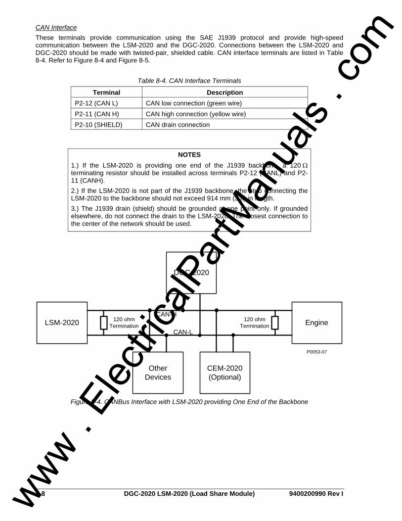
8-8 DGC-2020 LSM-2020 (Load Share Module) 9400200990 Rev I
CAN Interface These terminals provide communication using the SAE J1939 protocol and provide high-speed communication between the LSM-2020 and the DGC-2020. Connections between the LSM-2020 and DGC-2020 should be made with twisted-pair, shielded cable. CAN interface terminals are listed in Table 8-4. Refer to Figure 8-4 and Figure 8-5.
Table 8-4. CAN Interface Terminals
Terminal Description P2-12 (CAN L) CAN low connection (green wire) P2-11 (CAN H) CAN high connection (yellow wire) P2-10 (SHIELD) CAN drain connection
DGC-2020
LSM-2020
Other Devices
P0053-07
Engine120 ohmTermination
120 ohmTermination
CAN-H
CAN-L
CEM-2020 (Optional)
Figure 8-4. CANBus Interface with LSM-2020 providing One End of the Backbone
NOTES 1.) If the LSM-2020 is providing one end of the J1939 backbone, a 120 Ω terminating resistor should be installed across terminals P2-12 (CANL) and P2-11 (CANH). 2.) If the LSM-2020 is not part of the J1939 backbone, the stub connecting the LSM-2020 to the backbone should not exceed 914 mm (3 ft) in length. 3.) The J1939 drain (shield) should be grounded at one point only. If grounded elsewhere, do not connect the drain to the LSM-2020. The closest connection to the center of the network should be used.
www . El
ectric
alPar
tMan
uals
. com

9400200990 Rev I DGC-2020 LSM-2020 (Load Share Module) 8-9
LSM-2020
DGC-2020
Other Devices
P0053-08
Engine120 ohmTermination
120 ohmTermination
CAN-H
CAN-L
CEM-2020 (Optional)
Figure 8-5. CANBus Interface with DGC-2020 providing One End of the Backbone
Ethernet Port The LSM-2020 has Ethernet capability. The LSM-2020 connects to a PC through a RJ-45 jack (J3).
Connections for Typical Applications Figure 8-6 illustrates typical LSM-2020 connections.
123456789
101112131415161718
Ethernet
LSM-2020
AVR+
AVR-
AVR’
GOV+
GOV-
GOV’
CANL
CANH
GND
V+
IN-
I+
LS+
LS-
LS’
B-
B+
GND
Voltage Regulator
Analog Aux Input
Governor Analog Aux Input
DGC-2020CANL
CANH
SHIELD
To System Load Share Line
12 or 24 Vdc
P0052-42
Figure 8-6. Typical LSM-2020 Connections
www . El
ectric
alPar
tMan
uals
. com

8-10 DGC-2020 LSM-2020 (Load Share Module) 9400200990 Rev I
Connections using AVR’, GOV’, and LS’ Additional terminals provide a landing point to add series resistance to the GOV, AVR, and LS analog outputs. These terminals are not internally connected to the LSM-2020. Figure 8-7 illustrates connections using the additional AVR’ terminal as a landing point.
123456789
101112131415161718
Ethernet
LSM-2020
AVR+
AVR-
AVR’
GOV+
GOV-
GOV’
CANL
CANH
GND
V+
IN-
I+
LS+
LS-
LS’
B-
B+
GND
Voltage Regulator
Analog Aux Input
Governor Analog Aux Input
DGC-2020CANL
CANH
SHIELD
To System Load Share Line
12 or 24 Vdc
P0052-56
Figure 8-7. Connections using the AVR’ Terminal
MAINTENANCE Preventive maintenance consists of periodically checking that the connections between the LSM-2020 and the system are clean and tight. LSM-2020’s are manufactured using state-of-the-art surface-mount technology. As such, Basler Electric recommends that no repair procedures be attempted by anyone other than Basler Electric personnel.
www . El
ectric
alPar
tMan
uals
. com

9400200990 Rev I DGC-2020 CEM-2020 (Contact Expansion Module) i
SECTION 9 • CEM-2020 (CONTACT EXPANSION MODULE)
TABLE OF CONTENTS SECTION 9 • CEM-2020 (CONTACT EXPANSION MODULE) ............................................................... 9-1
GENERAL INFORMATION.................................................................................................................... 9-1 FEATURES............................................................................................................................................ 9-1 SPECIFICATIONS ................................................................................................................................. 9-1
Operating Power ................................................................................................................................ 9-1 Contact Inputs .................................................................................................................................... 9-1 Output Contacts ................................................................................................................................. 9-1 Communication Interface ................................................................................................................... 9-1 Type Tests.......................................................................................................................................... 9-1 Environment ....................................................................................................................................... 9-2 UL/CSA Approvals ............................................................................................................................. 9-2 NFPA Compliance.............................................................................................................................. 9-2 CE Compliance .................................................................................................................................. 9-2 Physical .............................................................................................................................................. 9-2
FUNCTIONAL DESCRIPTION .............................................................................................................. 9-2 Contact Inputs .................................................................................................................................... 9-2 Output Contacts ................................................................................................................................. 9-2 Communications................................................................................................................................. 9-2
BESTCOMSPlus SOFTWARE .............................................................................................................. 9-3 INSTALLATION...................................................................................................................................... 9-3
Product Registration........................................................................................................................... 9-3 Mounting............................................................................................................................................. 9-3 Connections........................................................................................................................................ 9-4
MAINTENANCE..................................................................................................................................... 9-6
Figures Figure 9-1. CEM-2020 Overall Dimensions............................................................................................... 9-3 Figure 9-2. Input Contact and Output Contact Terminals.......................................................................... 9-5 Figure 9-3. CANBus Interface with CEM-2020 providing One End of the Backbone ............................... 9-6 Figure 9-4. CANBus Interface with DGC-2020 providing One End of the Backbone ............................... 9-6
Tables Table 9-1. Operating Power Terminals ..................................................................................................... 9-4 Table 9-2. CAN Interface Terminals.......................................................................................................... 9-5
www . El
ectric
alPar
tMan
uals
. com

ii DGC-2020 CEM-2020 (Contact Expansion Module) 9400200990 Rev I
This page intentionally left blank.
www . El
ectric
alPar
tMan
uals
. com

9400200990 Rev I DGC-2020 CEM-2020 (Contact Expansion Module) 9-1
SECTION 9 • CEM-2020 (CONTACT EXPANSION MODULE)
GENERAL INFORMATION The optional CEM-2020 is a remote auxiliary device that provides additional contact inputs and outputs to the DGC-2020.
FEATURES CEM-2020’s have the following features: • 10 contact inputs • 24 output contacts • Functionality of Inputs and Outputs assigned by BESTLogic+ programmable logic • Communications via CANBUS
SPECIFICATIONS
Operating Power Nominal: 12 or 24 Vdc Range: 8 to 32 Vdc (Withstands cranking ride-through down to 6 Vdc
for 500 ms.)
Contact Inputs The CEM-2020 contains 10 programmable inputs that accept normally open and normally closed, dry contacts. Time from a CEM-2020 input going high to: Shutdown the generator via an alarm: 245 ms max Close a relay on board the DGC-2020: 245 ms max
Output Contacts Ratings Outputs 13 through 24: 1 Adc at 30 Vdc, Form C, gold contacts Outputs 25 through 36: 4 Adc at 30 Vdc, Form C
Communication Interface
CANBus Differential Bus Voltage: 1.5 to 3 Vdc Maximum Voltage: –32 to +32 Vdc with respect to negative battery terminal Communication Rate: 250 kb/s
Type Tests
Shock 15 G in 3 perpendicular planes
Vibration Swept over the following ranges for 12 sweeps in each of three mutually perpendicular planes with each 15-minute sweep consisting of the following: 5 to 29 to 5 Hz: 1.5 G peak for 5 min. 29 to 52 to 29 Hz: 0.036” Double Amplitude for 2.5 min. 52 to 500 to 52 Hz: 5 G peak for 7.5 min.
Ignition System Tested in closed proximity to an unshielded, unsuppressed Altronic DISN 800 ignition system.
www . El
ectric
alPar
tMan
uals
. com

9-2 DGC-2020 CEM-2020 (Contact Expansion Module) 9400200990 Rev I
HALT (Highly Accelerated Life Testing) HALT is used by many manufacturers to prove that their products will provide the user with many years of reliable service. HALT subjects the device to extremes in temperature, shock, and vibration to simulate years of operation, but in a much shorter period span. HALT allows Basler Electric to evaluate all possible design elements that will add to the life of this device. As an example of some of the extreme testing conditions, the CEM-2020 was subjected to temperature tests (tested over a temperature range of -80°C to +130°C), vibration tests (of 5 to 50 G at +25°C), and temperature/vibration tests (tested at 10 to 20 G over a temperature range of -60°C to +100°C). Combined temperature and vibration testing at these extremes proves that the CEM-2020 is expected to provide long-term operation in a rugged environment. Note that the vibration and temperature extremes listed in this paragraph are specific to HALT and do not reflect recommended operation levels. These operational ratings are included in Section 9 of this manual.
Environment Temperature Operating: –40 to 70°C (–40 to 158°F) Storage: –40 to 85°C (–40 to 185°F) Humidity: IEC 68-2-38
UL/CSA Approvals “cURus” recognized to UL 508 and CSA C22.2 No.14
NFPA Compliance Complies with NFPA Standard 110, Standard for Emergency and Standby Power.
CE Compliance This product complies with the requirements of the following EC Directives: • Low Voltage Directive (LVD) - 73/23/EEC as amended by 93/68/EEC • Electromagnetic Compatibility (EMC) - 89/336/EEC as amended by 92/31/EEC and 93/68/EEC
This product conforms to the following Harmonized Standards: • EN 50178:1997 - Electronic Equipment for use in Power Installations • EN 61000-6-4:2001 - Electromagnetic Compatibility (EMC), Generic Standards, Emission Standard
for Industrial Environments • EN 61000-6-2:2001 - Electromagnetic Compatibility (EMC), Generic Standards, Immunity for
Industrial Environments
Physical Weight: 1.02 kg (2.25 lb) Dimensions: See Installation later in this section.
FUNCTIONAL DESCRIPTION
Contact Inputs The CEM-2020 provides 10 programmable contact inputs with the same functionality as the contact inputs on the DGC-2020.
Output Contacts The CEM-2020 provides 24 programmable output contacts with the same functionality as the output contacts on the DGC-2020. Outputs 13 through 24 can carry 1 A. Outputs 25 through 36 can carry 4 A.
Communications
CANBus A Control Area Network (CAN) is a standard interface that enables communication between the CEM-2020 and the DGC-2020.
www . El
ectric
alPar
tMan
uals
. com
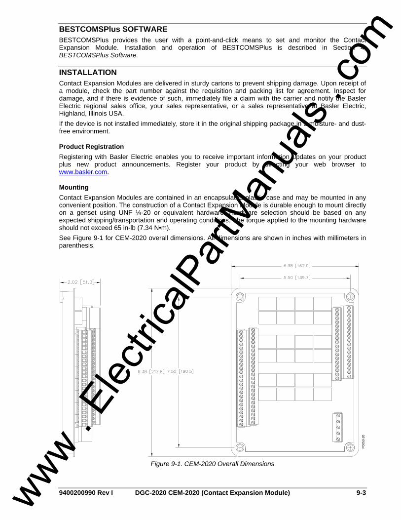
9400200990 Rev I DGC-2020 CEM-2020 (Contact Expansion Module) 9-3
BESTCOMSPlus SOFTWARE BESTCOMSPlus provides the user with a point-and-click means to set and monitor the Contact Expansion Module. Installation and operation of BESTCOMSPlus is described in Section 4, BESTCOMSPlus Software.
INSTALLATION Contact Expansion Modules are delivered in sturdy cartons to prevent shipping damage. Upon receipt of a module, check the part number against the requisition and packing list for agreement. Inspect for damage, and if there is evidence of such, immediately file a claim with the carrier and notify the Basler Electric regional sales office, your sales representative, or a sales representative at Basler Electric, Highland, Illinois USA. If the device is not installed immediately, store it in the original shipping package in a moisture- and dust-free environment.
Product Registration Registering with Basler Electric enables you to receive important information updates on your product plus new product announcements. Register your product by directing your web browser to www.basler.com.
Mounting Contact Expansion Modules are contained in an encapsulated plastic case and may be mounted in any convenient position. The construction of a Contact Expansion Module is durable enough to mount directly on a genset using UNF ¼-20 or equivalent hardware. Hardware selection should be based on any expected shipping/transportation and operating conditions. The torque applied to the mounting hardware should not exceed 65 in-lb (7.34 N•m). See Figure 9-1 for CEM-2020 overall dimensions. All dimensions are shown in inches with millimeters in parenthesis.
P00
53-2
0
Figure 9-1. CEM-2020 Overall Dimensions
www . El
ectric
alPar
tMan
uals
. com

9-4 DGC-2020 CEM-2020 (Contact Expansion Module) 9400200990 Rev I
Connections Contact Expansion Module connections are dependent on the application. Incorrect wiring may result in damage to the module.
Terminations The terminal interface consists of plug-in connectors with screw-down compression terminals. CEM-2020 connections are made with one 5-position connector, two 18-position connectors, and two 24-position connectors with screw-down compression terminals. These connectors plug into headers on the CEM-2020. The connectors and headers have dovetailed edges that ensure proper connector orientation. The connectors and headers are uniquely keyed to ensure that the connectors mate only with the correct headers. Connector screw terminals accept a maximum wire size of 12 AWG. Maximum screw torque is 5 inch-pounds (0.56 N•m).
Operating Power The Contact Expansion Module operating power input accepts either 12 Vdc or 24 Vdc and tolerates voltage over the range of 6 to 32 Vdc. Operating power must be of the correct polarity. Although reverse polarity will not cause damage, the CEM-2020 will not operate. Operating power terminals are listed in Table 9-1. It is recommended that a fuse be added for additional protection for the wiring to the battery input of the Contact Expansion Module. A Bussmann ABC-7 fuse or equivalent is recommended.
Table 9-1. Operating Power Terminals
Terminal Description
P1 (SHIELD) Chassis ground connection
P1 + (BATT–) Negative side of operating power input P1 – (BATT+) Positive side of operating power input
Contact Inputs The Contact Expansion Module has 10 contact inputs. Contact input terminals are shown in Figure 9-2.
Output Contacts The Contact Expansion Module has 24 output contacts. Output contact terminals are shown in Figure 9-2.
NOTE Operating power from the battery must be of the correct polarity. Although reverse polarity will not cause damage, the CEM-2020 will not operate. Be sure that the CEM-2020 is hard-wired to earth ground with no smaller than 12 AWG copper wire attached to the chassis ground terminal (P1 ) on the module.
www . El
ectric
alPar
tMan
uals
. com

9400200990 Rev I DGC-2020 CEM-2020 (Contact Expansion Module) 9-5
Figure 9-2. Input Contact and Output Contact Terminals
CAN Interface These terminals provide communication using the SAE J1939 protocol and provide high-speed communication between the Contact Expansion Module and the DGC-2020. Connections between the CEM-2020 and DGC-2020 should be made with twisted-pair, shielded cable. CAN interface terminals are listed in Table 9-2. Refer to Figure 9-3 and Figure 9-4.
Table 9-2. CAN Interface Terminals
Terminal Description P1 HI (CAN H) CAN high connection (yellow wire) P1 LO (CAN L) CAN low connection (green wire)
P1 (SHIELD) CAN drain connection
www . El
ectric
alPar
tMan
uals
. com

9-6 DGC-2020 CEM-2020 (Contact Expansion Module) 9400200990 Rev I
DGC-2020
CEM-2020
Other Devices
P0053-09
Engine120 ohmTermination
120 ohmTermination
CAN-H
CAN-L
LSM-2020 (Optional)
Figure 9-3. CANBus Interface with CEM-2020 providing One End of the Backbone
CEM-2020
DGC-2020
Other Devices
P0053-10
Engine120 ohmTermination
120 ohmTermination
CAN-H
CAN-L
LSM-2020 (Optional)
Figure 9-4. CANBus Interface with DGC-2020 providing One End of the Backbone
MAINTENANCE Preventive maintenance consists of periodically checking that the connections between the CEM-2020 and the system are clean and tight. Contact Expansion Modules are manufactured using state-of-the-art surface-mount technology. As such, Basler Electric recommends that no repair procedures be attempted by anyone other than Basler Electric personnel.
NOTES 1.) If the CEM-2020 is providing one end of the J1939 backbone, a 120 Ω terminating resistor should be installed across terminals P1 HI (CANH) and P1 LO (CANL). 2.) If the CEM-2020 is not part of the J1939 backbone, the stub connecting the CEM-2020 to the backbone should not exceed 914 mm (3 ft) in length. 3.) The J1939 drain (shield) should be grounded at one point only. If grounded elsewhere, do not connect the drain to the CEM-2020. The closest connection to the center of the network should be used.
www . El
ectric
alPar
tMan
uals
. com

9400200990 Rev I DGC-2020 Time Overcurrent Characteristic Curves i
APPENDIX A • TIME OVERCURRENT CHARACTERISTIC CURVES
TABLE OF CONTENTS APPENDIX A • TIME OVERCURRENT CHARACTERISTIC CURVES ...................................................A-1
INTRODUCTION ...................................................................................................................................A-1 CURVE SPECIFICATIONS ...................................................................................................................A-1 TIME OVERCURRENT CHARACTERISTIC CURVE GRAPHS...........................................................A-2
Time Dial Setting Cross-Reference....................................................................................................A-3
Figures Figure A-1. Time Characteristic Curve S, S1, Short Inverse (Similar to ABB CO-2) ................................A-5 Figure A-2. Time Characteristic Curve S2, Short Inverse (Similar To GE IAC-55)...................................A-6 Figure A-3. Time Characteristic Curve L, L1, Long Inverse (Similar to ABB CO-5) .................................A-7 Figure A-4. Time Characteristic Curve L2, Long Inverse (Similar To GE IAC-66)....................................A-8 Figure A-5. Time Characteristic Curve D, Definite Time (Similar To ABB CO-6) .....................................A-9 Figure A-6. Time Characteristic Curve M, Moderately Inverse (Similar to ABB CO-7)...........................A-10 Figure A-7. Time Characteristic Curve I, I1, Inverse Time (Similar to ABB CO-8) .................................A-11 Figure A-8. Time Characteristic Curve I2, Inverse Time (Similar to GE IAC-51)....................................A-12 Figure A-9. Time Characteristic Curve V, V1, Very Inverse (Similar to ABB CO-9) ...............................A-13 Figure A-10. Time Characteristic Curve V2, Very Inverse (Similar to GE IAC-53) .................................A-14 Figure A-11. Time Characteristic Curve E, E1, Extremely Inverse (Similar to ABB CO-11)...................A-15 Figure A-12. Time Characteristic Curve E2, Extremely Inverse (Similar to GE IAC-77) ........................A-16 Figure A-13. Time Characteristic Curve A, Standard Inverse.................................................................A-17 Figure A-14. Time Characteristic Curve B, Very Inverse ........................................................................A-18 Figure A-15. Time Characteristic Curve C, Extremely Inverse ...............................................................A-19 Figure A-16. Time Characteristic Curve G, Long Time Inverse ..............................................................A-20
Tables Table A-1. 51 Time Characteristic Curve Constants.................................................................................A-2 Table A-2. Characteristic Curve Cross-Reference....................................................................................A-3 Table A-3 .Time Dial Setting Cross-Reference .........................................................................................A-4
www . El
ectric
alPar
tMan
uals
. com

ii DGC-2020 Time Overcurrent Characteristic Curves 9400200990 Rev I
This page intentionally left blank.
www . El
ectric
alPar
tMan
uals
. com
9400200990 Rev I DGC-2020 Time Overcurrent Characteristic Curves A-1
APPENDIX A • TIME OVERCURRENT CHARACTERISTIC CURVES
INTRODUCTION The inverse time overcurrent characteristic curves provided by the DGC-2020 (style xxxxxxExx only) closely emulate most of the common electromechanical, induction-disk, overcurrent relays sold in North America.
CURVE SPECIFICATIONS Timing Accuracy: Within ±500 milliseconds of indicated operating
point. Sixteen inverse time functions and one fixed time
function can be selected. Characteristic curves for the inverse and definite time functions are defined by the following equation:
KDBCM
DAT NT +⋅+−
⋅= Equation A-1
TT = Time to trip when M ≥ 1 TR = Time to reset if relay is set for integrating
reset when M < 1. Otherwise, reset is 50 milliseconds or less
D = TIME DIAL setting (0.0 to 9.9) M = Multiple of PICKUP setting (0 to 40) A, B, C, N, K = Constants for the particular curve This equation complies with IEEE Standard
C37.112-1996. Table A-1 lists time characteristic curve
constants. See Figures A-1 through A-16 for graphs of the characteristics.
www . El
ectric
alPar
tMan
uals
. com

A-2 DGC-2020 Time Overcurrent Characteristic Curves 9400200990 Rev I
Table A-1. 51 Time Characteristic Curve Constants
Trip Characteristic Constants Curve Selection
Curve Name A B C N K
S1 S, S1, Short Inverse 0.2663 0.03393 1.0000 1.2969 0.0280 S2 S2, Short Inverse 0.0286 0.02080 1.0000 0.9844 0.0280 L1 L, L1, Long Inverse 5.6143 2.18592 1.0000 1.0000 0.0280 L2 L2, Long Inverse 2.3955 0.00000 1.0000 0.3125 0.0280 D D, Definite Time 0.4797 0.21359 1.0000 1.5625 0.0280 M M, Moderately Inverse 0.3022 0.12840 1.0000 0.5000 0.0280 I1 I, I1, Inverse Time 8.9341 0.17966 1.0000 2.0938 0.0280 I2 I2, Inverse Time 0.2747 0.10426 1.0000 0.4375 0.0280 V1 V, V1, Very Inverse 5.4678 0.10814 1.0000 2.0469 0.0280 V2 V2, Very Inverse 4.4309 0.09910 1.0000 1.9531 0.0280 E1 E, E1Extremely Inverse 7.7624 0.02758 1.0000 2.0938 0.0280 E2 E2, Extremely Inverse 4.9883 0.01290 1.0000 2.0469 0.0280 A A, Standard Inverse 0.01414 0.00000 1.0000 0.0200 0.0280
B B, Very Inverse (I2t) 1.4636 0.00000 1.0000 1.0469 0.0280
C C, Extremely Inverse (I2t) 8.2506 0.00000 1.0000 2.0469 0.0280
G G, Long Time Inverse (I2t) 12.1212 0.00000 1.0000 1.0000 0.0280
F Fixed Time ∗ 0.0000 1.00000 0.0000 0.0000 0.0280 ∗ Curve F has a fixed delay of one second times the Time Dial setting.
TIME OVERCURRENT CHARACTERISTIC CURVE GRAPHS Figures A-1 through A-16 illustrate the characteristic curves of the DGC-2020. Table A-2 cross-references each curve to existing electromechanical relay characteristics. Equivalent time dial settings were calculated at a value of five times pickup. A drawing number is provided in the caption of each graph.
www . El
ectric
alPar
tMan
uals
. com

9400200990 Rev I DGC-2020 Time Overcurrent Characteristic Curves A-3
Table A-2. Characteristic Curve Cross-Reference Curve Curve Name Similar To
S1 S, S1, Short Inverse ABB CO-2
S2 S2, Short Inverse GE IAC-55
L1 L, L1, Long Inverse ABB CO-5
L2 L2, Long Inverse GE IAC-66
D D, Definite Time ABB CO-6
M M, Moderately Inverse ABB CO-7
I1 I, I1, Inverse Time ABB CO-8
I2 I2, Inverse Time GE IAC-51
V1 V, V1, Very Inverse ABB CO-9
V2 V2, Very Inverse GE IAC-53
E1 E, E1, Extremely Inverse ABB CO-11
E2 E2, Extremely Inverse GE IAC-77
A A, Standard Inverse BS, IEC Standard Inverse
B B, Very Inverse (I2t) BS, IEC Very Inverse (I2t)
C C, Extremely Inverse (I2t) BS, IEC Extremely Inverse (I2t)
G G, Long Time Inverse (I2t) BS, IEC Long Time Inverse (I2t)
F Fixed Time N/A
Time Dial Setting Cross-Reference
Although the time characteristic curve shapes have been optimized for the DGC-2020, the DGC-2020 time dial settings are not identical to the settings of electromechanical induction disk overcurrent relays. Table A-3 helps you convert the time dial settings of induction disk relays to the equivalent setting for the DGC-2020.
Using Table A-3
Cross-reference table values were obtained by inspection of published electromechanical time current characteristic curves. The time delay for a current of five times tap was entered into the time dial calculator function for each time dial setting. The equivalent DGC-2020 time dial setting was then entered into the cross-reference table.
If your electromechanical relay time dial setting is between the values provided in the table, it will be necessary to interpolate (estimate the correct intermediate value) between the electromechanical setting and the Basler Electric setting.
The DGC-2020 has a maximum time dial setting of 9.9. The Basler Electric equivalent time dial setting for the electromechanical maximum setting is provided in the cross-reference table even if it exceeds 9.9. This allows interpolation as noted above.
Basler Electric time current characteristics are determined by a linear mathematical equation. The induction disk of an electromechanical relay has a certain degree of non linearity due to inertial and friction effects. For this reason, even though every effort has been made to provide characteristic curves with minimum deviation from the published electromechanical curves, slight deviations can exist between them.
In applications where the time coordination between curves is extremely close, we recommend that you choose the optimal time dial setting by inspection of the coordination study. In applications where coordination is tight, it is recommended that you retrofit your circuits with Basler Electric electronic relays to ensure high timing accuracy.
www . El
ectric
alPar
tMan
uals
. com

A-4 DGC-2020 Time Overcurrent Characteristic Curves 9400200990 Rev I
Table A-3 .Time Dial Setting Cross-Reference Electromechanical Relay Time Dial Setting
0.5 1.0 2.0 3.0 4.0 5.0 6.0 7.0 8.0 9.0 10.0 11.0 Curve Equivalent
To Basler Electric Equivalent Time Dial Setting
S, S1 ABB CO-2 0.3 0.8 1.7 2.4 3.4 4.2 5.0 5.8 6.7 7.7 8.6 9.7
L, L1 ABB CO-5 0.4 0.8 1.5 2.3 3.3 4.2 5.0 6.0 7.0 7.8 8.8 9.9
D ABB CO-6 0.5 1.1 2.0 2.9 3.7 4.5 5.0 5.9 7.2 8.0 8.9 10.1
M ABB CO-7 0.4 0.8 1.7 2.5 3.3 4.3 5.3 6.1 7.0 8.0 9.0 9.8
I, I1 ABB CO-8 0.3 0.7 1.5 2.3 3.2 4.0 5.0 5.8 6.8 7.6 8.7 10.0
V, V1 ABB CO-9 0.3 0.7 1.4 2.1 3.0 3.9 4.8 5.7 6.7 7.8 8.7 9.6
E, E1 ABB CO-11 0.3 0.7 1.5 2.4 3.2 4.2 5.0 5.7 6.6 7.8 8.5 10.3
I2 GE IAC-51 0.6 1.0 1.9 2.7 3.7 4.8 5.7 6.8 8.0 9.3 10.6 N/A
V2 GE IAC-53 0.4 0.8 1.6 2.4 3.4 4.3 5.1 6.3 7.2 8.4 9.6 N/A
S2 GE IAC-55 0.2 1.0 2.0 3.1 4.0 4.9 6.1 7.2 8.1 8.9 9.8 N/A
L2 GE IAC-66 0.4 0.9 1.8 2.7 3.9 4.9 6.3 7.2 8.5 9.7 10.9 N/A
E2 GE IAC-77 0.5 1.0 1.9 2.7 3.5 4.3 5.2 6.2 7.4 8.2 9.9 N/A
www . El
ectric
alPar
tMan
uals
. com
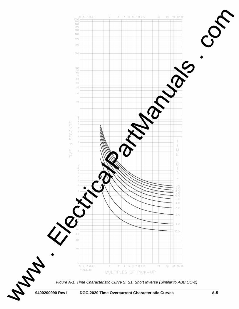
9400200990 Rev I DGC-2020 Time Overcurrent Characteristic Curves A-5
Figure A-1. Time Characteristic Curve S, S1, Short Inverse (Similar to ABB CO-2)
www . El
ectric
alPar
tMan
uals
. com
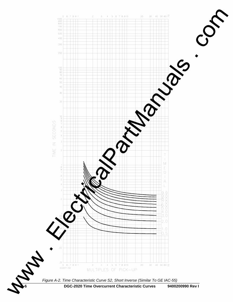
A-6 DGC-2020 Time Overcurrent Characteristic Curves 9400200990 Rev I
Figure A-2. Time Characteristic Curve S2, Short Inverse (Similar To GE IAC-55)
www . El
ectric
alPar
tMan
uals
. com

9400200990 Rev I DGC-2020 Time Overcurrent Characteristic Curves A-7
Figure A-3. Time Characteristic Curve L, L1, Long Inverse (Similar to ABB CO-5)
www . El
ectric
alPar
tMan
uals
. com
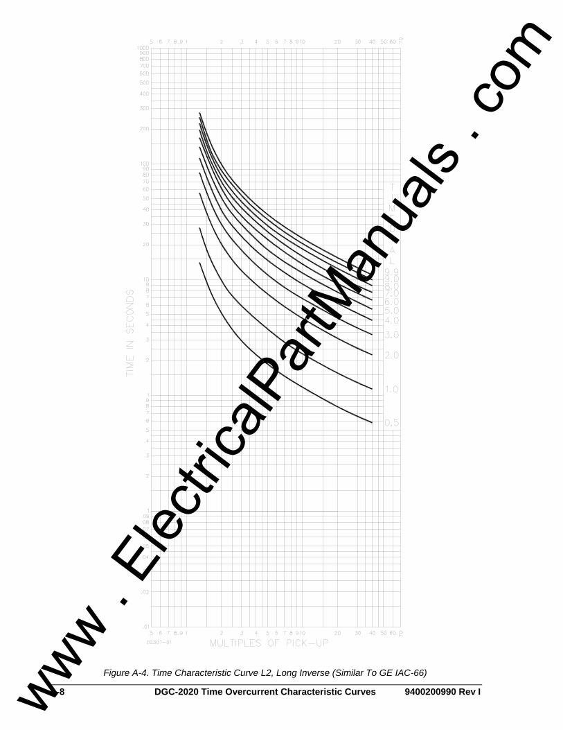
A-8 DGC-2020 Time Overcurrent Characteristic Curves 9400200990 Rev I
Figure A-4. Time Characteristic Curve L2, Long Inverse (Similar To GE IAC-66)
www . El
ectric
alPar
tMan
uals
. com
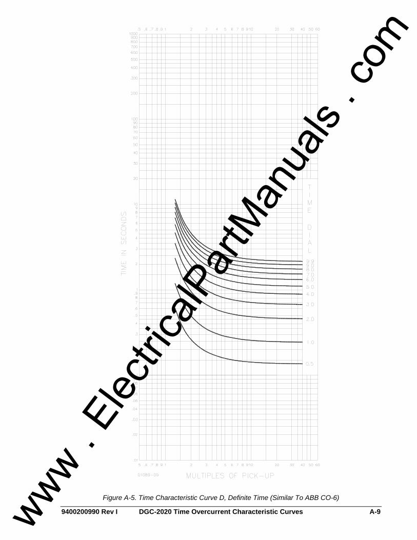
9400200990 Rev I DGC-2020 Time Overcurrent Characteristic Curves A-9
Figure A-5. Time Characteristic Curve D, Definite Time (Similar To ABB CO-6)
www . El
ectric
alPar
tMan
uals
. com

A-10 DGC-2020 Time Overcurrent Characteristic Curves 9400200990 Rev I
Figure A-6. Time Characteristic Curve M, Moderately Inverse (Similar to ABB CO-7)
www . El
ectric
alPar
tMan
uals
. com
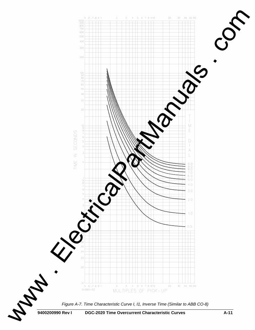
9400200990 Rev I DGC-2020 Time Overcurrent Characteristic Curves A-11
Figure A-7. Time Characteristic Curve I, I1, Inverse Time (Similar to ABB CO-8)
www . El
ectric
alPar
tMan
uals
. com

A-12 DGC-2020 Time Overcurrent Characteristic Curves 9400200990 Rev I
Figure A-8. Time Characteristic Curve I2, Inverse Time (Similar to GE IAC-51)
www . El
ectric
alPar
tMan
uals
. com

9400200990 Rev I DGC-2020 Time Overcurrent Characteristic Curves A-13
Figure A-9. Time Characteristic Curve V, V1, Very Inverse (Similar to ABB CO-9)
www . El
ectric
alPar
tMan
uals
. com

A-14 DGC-2020 Time Overcurrent Characteristic Curves 9400200990 Rev I
Figure A-10. Time Characteristic Curve V2, Very Inverse (Similar to GE IAC-53)
www . El
ectric
alPar
tMan
uals
. com

9400200990 Rev I DGC-2020 Time Overcurrent Characteristic Curves A-15
Figure A-11. Time Characteristic Curve E, E1, Extremely Inverse (Similar to ABB CO-11)
www . El
ectric
alPar
tMan
uals
. com

A-16 DGC-2020 Time Overcurrent Characteristic Curves 9400200990 Rev I
Figure A-12. Time Characteristic Curve E2, Extremely Inverse (Similar to GE IAC-77)
www . El
ectric
alPar
tMan
uals
. com

9400200990 Rev I DGC-2020 Time Overcurrent Characteristic Curves A-17
Figure A-13. Time Characteristic Curve A, Standard Inverse
www . El
ectric
alPar
tMan
uals
. com

A-18 DGC-2020 Time Overcurrent Characteristic Curves 9400200990 Rev I
Figure A-14. Time Characteristic Curve B, Very Inverse
www . El
ectric
alPar
tMan
uals
. com

9400200990 Rev I DGC-2020 Time Overcurrent Characteristic Curves A-19
Figure A-15. Time Characteristic Curve C, Extremely Inverse
www . El
ectric
alPar
tMan
uals
. com

A-20 DGC-2020 Time Overcurrent Characteristic Curves 9400200990 Rev I
Figure A-16. Time Characteristic Curve G, Long Time Inverse
www . El
ectric
alPar
tMan
uals
. com
9400200990 Rev I DGC-2020 Modbus™ Communication i
APPENDIX B • MODBUS™ COMMUNICATION TABLE OF CONTENTS
INTRODUCTION .......................................................................................................................... B-1
General Overview .................................................................................................................. B-1 Intended Use of the Communications Protocol .....................................................................B-1
DETAILED DESCRIPTION OF DGC-2020 MODBUS PROTOCOL............................................B-1 Modbus Protocol Overview ....................................................................................................B-1 Serial Transmission Details ...................................................................................................B-2 Message Framing / Timing Considerations ...........................................................................B-2 Error Handling and Exception Responses.............................................................................B-2
DETAILED DGC-2020 MESSAGE DEFINITION .........................................................................B-2 Device Address ...................................................................................................................... B-2 Function Code and Data Block ..............................................................................................B-2
DATA FORMATS ......................................................................................................................... B-5 Short Integer Data Format (INT8) ..........................................................................................B-5 Integer Data Format (INT16)..................................................................................................B-5 Long Integer Data Format (INT32).........................................................................................B-6 Floating Point Data Format ....................................................................................................B-6 Double Precision Data Format (DP) ......................................................................................B-7 Triple Precision Data Format (TP) .........................................................................................B-7 Error Check ............................................................................................................................ B-7 Interdependence of Preset Multiple Register Data ................................................................B-7
MAPPING - DGC 2020 Parameters into MODICON ADDRESS SPACE....................................B-8 Table Conventions ................................................................................................................. B-8 Legacy Parameter Table........................................................................................................B-8 Current Parameter Table .....................................................................................................B-21
www . El
ectric
alPar
tMan
uals
. com

ii DGC-2020 Modbus™ Communication 9400200990 Rev I
This page intentionally left blank.
www . El
ectric
alPar
tMan
uals
. com

9400200990 Rev I DGC-2020 Modbus™ Communication B-1
APPENDIX B • MODBUS™ COMMUNICATION INTRODUCTION
General Overview An optional feature of the DGC-2020 performs Modbus communications by emulating a subset of the Modicon 984 Programmable Controller. This document describes the Modbus communications protocol employed by the DGC-2020 and how to exchange information with the DGC-2020 over a Modbus network. The DGC-2020 maps all parameters into the Modicon 984 Holding Register address space (4XXXX). Refer to MAPPING - DGC 2020 Parameters into MODICON ADDRESS SPACE in this section. The 40XXX registers are identical to the data that was present in the DGC-500 and DGC-1000 products. This allows the DGC-2020 to work seamlessly in Modbus applications where it is replacing a DGC-500 or DGC-1000. The 42XXX registers contain all information included in the DGC-2020 and should be used for any new Modbus applications.
Intended Use of the Communications Protocol This document provides the necessary information for 3rd party OEMs to develop in-house software to communicate with the DGC-2020 via Modbus protocol. This will allow the exchange of setup information and measured data between a Modbus Master Station and the DGC-2020. The DGC-2020 data supported for remote access is listed in MAPPING - DGC 2020 Parameters into MODICON ADDRESS SPACE in this section.
DETAILED DESCRIPTION OF DGC-2020 MODBUS PROTOCOL
Modbus Protocol Overview Modbus communications use a master-slave technique in which only the master can initiate a transaction, called a query. The slave addressed by the query will respond by either supplying the requested data to the master or by performing the requested action. A slave device never initiates communications on the Modbus, and will always generate a response to the query unless certain error conditions occur. The DGC-2020 is designed to communicate on the Modbus only as a slave device. A master can query slaves individually or query all slaves collectively by initiating a broadcast message. A slave does not send a response message to a broadcast query. If a query requests actions unable to be performed by the slave, the slave response message will contain an Exception Response Code defining the error detected. Query and response messages share the same message structure. Each message is comprised of four message fields: the Device Address, the Function Code, the Data Block, and the Error Check field. Subsequent sections in this document detail each message field and the corresponding functionality supported by the DGC-2020. Query / Response Message Structure: • Device Address • Function Code • Eight-Bit Data Bytes • Error Check
Device Address Field The Device Address field contains the unique Modbus address of the slave being queried. The addressed slave will repeat its address in the Device Address field of the response message. This field is 1 byte.
Function Code Field The Function Code field in the Query message defines the action to be taken by the addressed slave. This field is echoed in the Response message, and will be altered by setting the MSB of the field to "1" if the response is an error response. This field is 1 byte.
www . El
ectric
alPar
tMan
uals
. com

B-2 DGC-2020 Modbus™ Communication 9400200990 Rev I
Data Block Field The query Data block contains additional information needed by the slave to perform the requested function. The response Data block contains data collected by the slave for the queried function. An error response will substitute an Exception Response Code for the Data Block. The length of this field varies with each query.
Error Check Field The Error Check field provides a method for the slave to validate the integrity of the query message contents and allows the master to confirm the validity of response message contents. This field is 2 bytes.
Serial Transmission Details A standard Modbus network offers 2 transmission modes for communication: ASCII or RTU. The DGC-2020 supports only the RTU (Remote Terminal Unit) mode. Each 8-bit byte in a message contains two 4-bit hexadecimal characters. The message is transmitted in a continuous stream with the LSB of each byte of data transmitted first. Transmission of each 8-bit data byte occurs with 1 start bit and 1 stop bit. A ninth data bit is added when parity is selected. Parity checking is user-configurable to even, odd or none. The transmission baud rate is also user-configurable, and both parity and baud rate can be altered during real-time operation. If altered, the new baud rate and / or parity will not be enforced until the response message to the current query has completed. The DGC-2020 supported baud rates are 9600, 4800, 2400, and 1200.
Message Framing / Timing Considerations When receiving a message, the DGC-2020 will allow maximum inter-byte latency up to 3.5 - 4.0 character times before considering the message complete. Once a valid query is received, the DGC-2020 waits 10 msec. before responding.
Error Handling and Exception Responses Any query received that contains a non-existent device address, a framing error or CRC error will be ignored - no response will be transmitted. Queries addressed to a DGC-2020 with an unsupported function code, unsupported register references, or illegal values in the data block will result in an error response message with an Exception Response Code. The Exception Response codes supported by the DGC-2020 are listed in Table B-1.
Table B-1. Exception Response Codes Code Name Meaning
01 Illegal Function The query Function/Subfunction Code is unsupported; query read of more than 125 registers; query preset of more than 100 registers
02 Illegal Data Address A register referenced in the data block does not support queried read/write; query preset of a subset of a numerical register group.
03 Illegal Data Value A preset register data block contains an incorrect number of bytes or one or more data values out of range.
DETAILED DGC-2020 MESSAGE DEFINITION
Device Address The DGC-2020 Device Address can be any value in the Modbus protocol Device Address range (1 - 247). A query with a Device Address of 0 signifies a Broadcast message to all slaves - the connected DGC-2020s will not respond to the broadcast query.
Function Code and Data Block The DGC-2020 maps all parameters into the Modicon 984 Holding Register address space (4XXXX) and supports the following Function Codes: • Function 03 - Read Holding Registers • Function 6 - Preset Single Register, Non-Broadcast & Broadcast
www . El
ectric
alPar
tMan
uals
. com

9400200990 Rev I DGC-2020 Modbus™ Communication B-3
• Function 08, Subfunction 00 - Diagnostics: Return Query Data • Function 16 - Preset Multiple Registers, Non-Broadcast & Broadcast
The only Broadcast query supported by the DGC-2020 is the Preset Multiple Registers query.
Read Holding Registers Read Holding Registers - General QUERY: This query message requests a register or block of registers to be read. The data block contains the starting register address and the quantity of registers to be read. A register address of N will read Holding Register N+1.
Device Address Function Code 03 (hex) Starting Address Hi Starting Address Lo No. of Registers Hi No. of Registers Lo CRC Error Check
The number of registers cannot exceed 125 without causing an error response with Exception Code "Illegal Function". Queries to read Write Only or unsupported registers result in an error response with Exception Code of “Illegal Data Address”. RESPONSE: The response message contains the data queried, respectively. The data block contains the block length in bytes followed by the data for each requested register. Attempting to read an unused register or a register which does not support read results in an error response with Exception Code of "Illegal Data Address".
Device Address Function Code 03 (hex) Byte Count Data Hi Data Lo . . . Data Hi Data Lo CRC Error Check
Return Query Data This query contains data to be returned (looped back) in the response. The response and query messages should be identical.
Device Address Function Code 08 (hex) Subfunction Hi 00 (hex) Subfunction Lo 00 (hex) Data Hi Data Lo CRC Error Check
www . El
ectric
alPar
tMan
uals
. com

B-4 DGC-2020 Modbus™ Communication 9400200990 Rev I
Preset Multiple Registers, Non-Broadcast & Broadcast Preset Multiple Registers - General QUERY: This query message requests a register or block of registers to be written. The data block contains the starting address and the quantity of registers to be written, followed by the Data Block byte count and data. A device address is 0 for a broadcast query. A register address of N will write Holding Register N+1. No query data will be written (non-broadcast or broadcast) if any of the following exceptions occur: • Queries writing to Read Only or unsupported registers result in an error response with Exception
Code of “Illegal Data Address”. • Queries attempting to write more than 100 registers cause an error response with Exception Code
“Illegal Function”. • An incorrect Byte Count will result in an error response with Exception Code of “Illegal Data Value”. • There are several instances of registers that are grouped together (signified as DP or TP) to
collectively represent a single numerical (vs. ASCII string) DGC-2020 parameter value. A query to write a subset of such a register group will result in an error response with Exception Code “Illegal Data Address”.
• A query to write an unallowed value (out of range) to a register results in an error response with Exception Code of “Illegal Data Value”.
Device Address Function Code 10 (hex) Starting Address Hi Starting Address Lo No. of Registers Hi No. of Registers Lo Byte Count Data Hi Data Lo . . . Data Hi Data Lo CRC Error Check
RESPONSE: The response message echoes the starting address and the number of registers. There is no response message when the query is broadcast. Device Address Function Code 10 (hex) Starting Address Hi Starting Address Lo No. of Registers Hi No. of Registers Lo CRC Error Check
Preset Single Register, Non-Broadcast & Broadcast QUERY: This query message requests a register to be written. A device address is 0 for a broadcast query. No query data will be written (non-broadcast or broadcast) if any of the following exceptions occur: • Queries writing to Read Only or unsupported registers result in an error response with Exception
Code of “Illegal Data Address”.
www . El
ectric
alPar
tMan
uals
. com

9400200990 Rev I DGC-2020 Modbus™ Communication B-5
• There are several instances of registers that are grouped together (signified as DP or TP) to collectively represent a single numerical (vs. ASCII string) DGC-2020 parameter value. A query to write a subset of such a register group will result in an error response with Exception Code “Illegal Data Address”.
• A query to write an unallowed value (out of range) to a register results in an error response with Exception Code of “Illegal Data Value”.
Device Address Function Code 06 (hex) Address Hi Address Lo Data Hi Data Lo CRC Error Check
RESPONSE: The response message echoes the address and the value written. There is no response message when the query is broadcast.
Device Address Function Code 06 (hex) Address Hi Address Lo Data Hi Data Lo CRC Error Check
DATA FORMATS
Short Integer Data Format (INT8) The Modbus short integer data format uses a single holding register to represent an 8 bit data value. The holding register high byte will always be zero. Example: The value 132 represented in short integer format is hexadecimal 0x84. This number will read from a holding register as follows: Holding Register Value K (Hi Byte) hex 00 K (Lo Byte) hex 84 The same byte alignments are required to write.
Integer Data Format (INT16) The Modbus integer data format uses a single holding register to represent a 16-bit data value. Example: The value 4660 represented in integer format is hexadecimal 0x1234. This number will read from a holding register as follows: Holding Register Value K (Hi Byte) hex 12 K (Lo Byte) hex 34
www . El
ectric
alPar
tMan
uals
. com
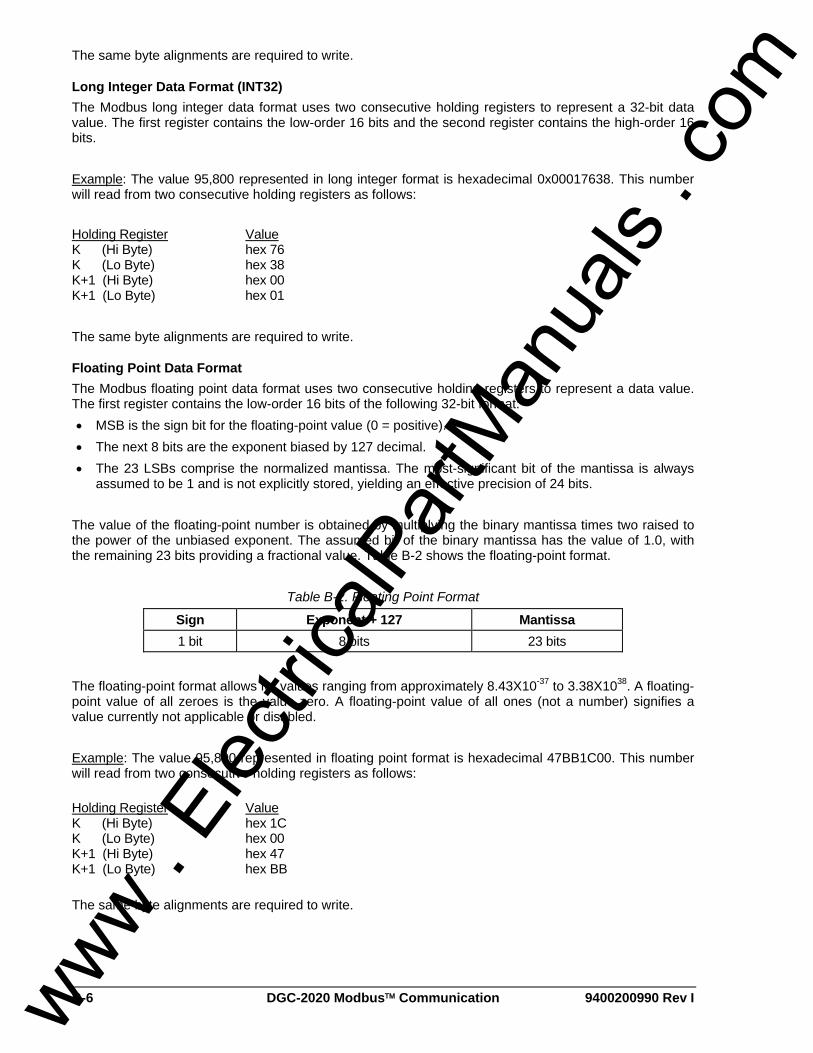
B-6 DGC-2020 Modbus™ Communication 9400200990 Rev I
The same byte alignments are required to write.
Long Integer Data Format (INT32) The Modbus long integer data format uses two consecutive holding registers to represent a 32-bit data value. The first register contains the low-order 16 bits and the second register contains the high-order 16 bits. Example: The value 95,800 represented in long integer format is hexadecimal 0x00017638. This number will read from two consecutive holding registers as follows: Holding Register Value K (Hi Byte) hex 76 K (Lo Byte) hex 38 K+1 (Hi Byte) hex 00 K+1 (Lo Byte) hex 01 The same byte alignments are required to write.
Floating Point Data Format The Modbus floating point data format uses two consecutive holding registers to represent a data value. The first register contains the low-order 16 bits of the following 32-bit format: • MSB is the sign bit for the floating-point value (0 = positive). • The next 8 bits are the exponent biased by 127 decimal. • The 23 LSBs comprise the normalized mantissa. The most-significant bit of the mantissa is always
assumed to be 1 and is not explicitly stored, yielding an effective precision of 24 bits. The value of the floating-point number is obtained by multiplying the binary mantissa times two raised to the power of the unbiased exponent. The assumed bit of the binary mantissa has the value of 1.0, with the remaining 23 bits providing a fractional value. Table B-2 shows the floating-point format.
Table B-2. Floating Point Format
Sign Exponent + 127 Mantissa 1 bit 8 bits 23 bits
The floating-point format allows for values ranging from approximately 8.43X10-37 to 3.38X1038. A floating-point value of all zeroes is the value zero. A floating-point value of all ones (not a number) signifies a value currently not applicable or disabled. Example: The value 95,800 represented in floating point format is hexadecimal 47BB1C00. This number will read from two consecutive holding registers as follows: Holding Register Value K (Hi Byte) hex 1C K (Lo Byte) hex 00 K+1 (Hi Byte) hex 47 K+1 (Lo Byte) hex BB The same byte alignments are required to write.
www . El
ectric
alPar
tMan
uals
. com

9400200990 Rev I DGC-2020 Modbus™ Communication B-7
Double Precision Data Format (DP) The Modbus Double Precision data format (DP) uses 2 consecutive registers to represent a data value. The first register contains the high-order 16 bits of double precision data, and is the actual data value / 10,000. The second register contains the low-order 16 bits of double precision data, and is the actual data value modulus 10,000.
Triple Precision Data Format (TP) The Modbus Triple Precision data format (TP) uses 3 consecutive registers to represent a data value. The first register contains the high-order 16 bits of triple precision data, and is the actual data value / 100,000,000. The modulus from this operation is divided by 10,000 to arrive at the value of the second register, and the modulus of this last operation is the value of the third register (the low-order 16 bits of triple precision).
Error Check This field contains a 2-byte CRC value for transmission error detection. The master first calculates the CRC and appends it to the query message. The DGC-2020 recalculates the CRC value for the received query and performs a comparison to the query CRC value to determine if a transmission error has occurred. If so, no response message is generated. Otherwise, the slave calculates a new CRC value for the response message and appends it to the message for transmission. Reference the "Modicon Modbus Protocol Reference Guide", PI-MBUS-300 Rev. E, pages 112 - 115 for an excellent explanation and implementation of the CRC-16 algorithm. The CRC calculation is performed using all bytes of the Device Address, Function Code, and Data Block fields. A 16-bit CRC-register is initialized to all 1's. Then each 8-bit byte of the message is used in the following algorithm: First, exclusive-OR the message byte with the low-order byte of the CRC-register. The result, stored in the CRC-register, will then be right-shifted 8 times. The CRC-register MSB is zero-filled with each shift. After each shift the CRC-register LSB is examined: if 1, the CRC-register is then exclusive-ORed with the fixed polynomial value A001 (hex) prior to the next shift. Once all bytes of the message have undergone the above algorithm, the CRC-register will contain the message CRC value to be placed in the Error Check field.
Interdependence of Preset Multiple Register Data Preset Multiple Register data is collectively written only after the query has been determined to be legal, which includes a range-check of the entire data block. Therefore, data which must be written prior to other data must use a separate query. For example, a Preset Multiple Register Query of the entire Contiguous Write Block (40023-40055) to set the Battery Overvoltage Pre-alarm Threshold atop the 24V range and change the Battery Volts from 12V to 24V will fail. The change to 24V would occur simultaneously to setting the Pre-alarm Threshold, and the threshold value range-check will use the current 12V range.
www . El
ectric
alPar
tMan
uals
. com

B-8 DGC-2020 Modbus™ Communication 9400200990 Rev I
MAPPING - DGC 2020 PARAMETERS INTO MODICON ADDRESS SPACE
Table Conventions Table B-3 uses the conventions outlined in this section. The “Data Format” column uses the following abbreviations: • DP - Double Precision • TP - Triple Precision • FP – Floating Point
Data formatted in Double Precision uses a 2 register group designated (a) and (b) and is defined as follows: • Register (a) - 2 hi-order bytes • Register (b) - 2 lo-order bytes
Data formatted in Triple Precision uses a 3 register group designated (a), (b) and (x). It is defined as follows: • Register (a) - 2 hi-order bytes • Register (b) - 2 mid-order bytes • Register (x) - 2 lo-order bytes
Other register groups using the (a), (b), etc. designators are an ordered data group of consecutive ASCII characters or data bytes.
Legacy Parameter Table The DGC-2020 maps all legacy parameters previously associated with the DGC-500 and DGC-1000 into the Holding Register address space (40000 to 41999). Query address N will access the Holding Register N+1. The Data Format is Integer type data unless identified otherwise in the Data Format column.
www . El
ectric
alPar
tMan
uals
. com

9400200990 Rev I DGC-2020 Modbus™ Communication B-9
Table B-3. Legacy Parameter Table Holding Register Parameter Range Read/Write
Supported Data
Format Units
40001-18 RESERVED
PARAMETER SETTINGS
40019 Emergency Stop 0-1 W 0 =Off 1 =Stop
40020 Remote Start / Stop 0-1 W 0 =Stop 1 =Start
40021-22 RESERVED SYSTEM PARAMETERS
40023 Default Generator Connection 0-2 R W 0=3ph L-L 1=3ph L-N 2=1ph A-B
40024 NFPA Level 0-2 R W 0=Off 1=Level 1 2=Level 2
40025 RESERVED 40026 Rated Engine RPM 750-3600 R W RPM 40027 Number Flywheel Teeth 50-500 R W 40028 Genset KW Rating 25-9999 R W KWatt 40029 No Load Cool Down Time 0-60 R W Minutes GENERATOR PT PRIMARY 40030 Voltage(a) 1-15000 R W DP VoltsAC x10000 40031 Voltage(b) R W DP VoltsAC GENERATOR PT SECONDARY 40032 Voltage 1-480 R W VoltsAC GENERATOR CT PRIMARY 40033 Current 1-5000 R W AmpsAC LOW FUEL ALARM
40034 Enable 0-1 R W 0 =Off 1 =On
40035 Threshold 2-50 R W % Full Tank LOW FUEL PRE-ALARM
40036 Enable 0-1 R W 0 =Off 1 =On
40037 Threshold 10-100 R W % Full Tank LOW COOLANT TEMP PRE-ALARM
40038 Enable 0-1 R W 0 =Off 1 =On
40039 Threshold 32-150 R W Degrees F BATTERY OVERVOLTAGE PRE-ALARM
40040 Enable 0-1 R W 0 =Off 1 =On
40041 RESERVED MAINTENANCE INTERVAL PRE-ALARM
40042 Enable 0-1 R W 0 =Off 1 =On
40043 Threshold 0-5000 R W Hours ENGINE KW OVERLOAD PRE-ALARM
40044 Enable 0-1 R W 0 =Off 1 =On
40045 Threshold 95-140 R W % of Rated HIGH COOLANT TEMP PRE-ALARM
40046 Enable 0-1 R W 0 =Off 1 =On
40047 Threshold 100-280 R W Degrees F LOW OIL PRESSURE PRE-ALARM
40048 Enable 0-1 R W 0 =Off 1 =On
www . El
ectric
alPar
tMan
uals
. com

B-10 DGC-2020 Modbus™ Communication 9400200990 Rev I
Holding Register Parameter Range Read/Write
Supported Data
Format Units
40049 Threshold 3-100 R W PSI LOW BATTERY VOLTAGE PRE-ALARM
40050 Enable 0-1 R W 0 =Off 1 =On
40051 Threshold 60-120 (12V) 120-240 (24V) R W .1 Volts DC
40052 Pre-alarm Activation Time Delay 1-10 R W Seconds WEAK BATTERY VOLTAGE PRE-ALARM
40053 Enable 0-1 R W 0 =Off 1 =On
40054 Threshold 40-80 (12V) 80-160 (24V) R W .1 VoltDC
40055 Pre-alarm Activation Time Delay 1-10 R W Seconds 40056-59 RESERVED HIGH COOLANT TEMP ALARM
40060 Enable 0-1 R W 0 =Off 1 =On
40061 Threshold 100-280 R W Degrees F
40062 Arming Delay after Crank Disconnect 60 R W Seconds
LOW OIL PRESSURE ALARM
40063 Enable 0-1 R W 0 =Off 1 =On
40064 Threshold 3-100 R W PSI
40065 Arming Delay after Crank Disconnect 5-15 R W Seconds
OVERSPEED ALARM
40066 Enable 0-1 R W 0 =Off 1 =On
40067 Threshold 105-140 R W % of Rated 40068 Alarm Activation Time Delay 0-500 R W MilliSec 40069-71 RESERVED CRANKING PARAMETERES
40072 Cranking Style 0-1 R W 0=Contin. 1=Cycle
40073 Number of Crank Cycles 1-7 R W 40074 Cycle Crank Time 5-15 R W Seconds 40075 Continuous Crank Time 1-60 R W Seconds 40076 Crank Disconnect Limit 10-100 R W % of Rated 40077 Pre-crank Delay 0-30 R W Seconds SYSTEM MONITOR 40078 Remaining Cooldown Time 0-60 R - Minutes 40079 RESERVED
40080 Active Speed Signal Sources 1-4 R -
1=MPU 2=ALT 3=GEN 4=NONE
40081 Sender Failure Alarm Code individual bits are 0 or 1 R -
b0=High Coolant Temperature b1=Oil Pressure b2 Fuel Level b3=Generator Voltage Sensing b4=Magnetic Pick-up b5-b7 not used
www . El
ectric
alPar
tMan
uals
. com

9400200990 Rev I DGC-2020 Modbus™ Communication B-11
Holding Register Parameter Range Read/Write
Supported Data
Format Units
40082 Alarm Codes individual bits are 0 or 1 R -
b0=High Coolant Temperature b1=Low Coolant Level b2=Low Fuel Level b3=Emergency Stop b4=Sender Failure b5=Over Crank b6=Over Speed b7=Low Oil Pressure Rev. 3.04 Added: b8 = CAN Fail
40083 Pre-Alarm Codes individual bits are 0 or 1 R -
b0=High Coolant Temperature b1=Low Coolant Temperature b2=Weak Battery b3=Low Battery b4=Battery Overvoltage b5=Battery Charger Fail b6=Maintenance Interval b7=Engine Overload Rev. 3.04 Added: b8 = DTC b9 = CAN Fail
40084 Pre-Alarm Codes, Group 2 individual bits are 0 or 1 R -
b0=Low Oil Pressure b1=Low Fuel Level b2=Magnetic Pick-up Fail b3=Fuel Level Sender Fail b4=Aux Input 1 b5=Aux Input 2 b6=Aux Input 3 b7=Aux Input 4
40085 Engine Coolant Temperature R - DegF 40086 Engine Oil Pressure R - PSI 40087 Battery Voltage R - .1 VoltsDC 40088 Fuel Level R - % Full Tank 40089 Time Remaining until Maintenance R - Hours 40090 Accumulated Engine Runtime(a) R W DP Minutes x 10000 40091 Accumulated Engine Runtime(b) R W DP Minutes 40092 Not Currently Used R W DP 40093 Not Currently Used R W DP 40094 Engine Speed(a) R - DP RPM x10000 40095 Engine Speed(b) R - DP RPM 40096 Engine Load(a) R - DP 40097 Engine Load(b) R - DP % of Rated Load GENERATOR MONITOR
40098 Phase a-b RMS Voltage(a) R - DP RMS Volt x 10000
40099 Phase a-b RMS Voltage(b) R - DP RMS Volt
40100 Phase b-c RMS Voltage(a) R - DP RMS Volt x 10000
40101 Phase b-c RMS Voltage(b) R - DP RMS Volt
40102 Phase c-a RMS Voltage(a) R - DP RMS Volt x 10000
40103 Phase c-a RMS Voltage(b) R - DP RMS Volt
40104 Phase a-n RMS Voltage(a) R - DP RMS Volt x 10000
40105 Phase a-n RMS Voltage(b) R - DP RMS Volt
40106 Phase b-n RMS Voltage(a) R - DP RMS Volt x 10000
40107 Phase b-n RMS Voltage(b) R - DP RMS Volt
40108 Phase c-n RMS Voltage(a) R - DP RMS Volt x 10000
40109 Phase c-n RMS Voltage(b) R - DP RMS Volt
www . El
ectric
alPar
tMan
uals
. com
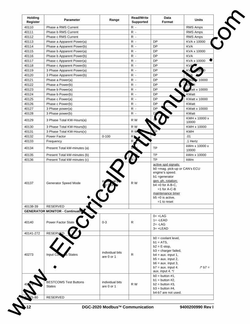
B-12 DGC-2020 Modbus™ Communication 9400200990 Rev I
Holding Register Parameter Range Read/Write
Supported Data
Format Units
40110 Phase a RMS Current R - RMS Amps 40111 Phase b RMS Current R - RMS Amps 40112 Phase c RMS Current R - RMS Amps 40113 Phase a Apparent Power(a) R - DP KVA x 10000 40114 Phase a Apparent Power(b) R - DP KVA 40115 Phase b Apparent Power(a) R - DP KVA x 10000 40116 Phase b Apparent Power(b) R - DP KVA 40117 Phase c Apparent Power(a) R - DP KVA x 10000 40118 Phase c Apparent Power(b) R - DP KVA 40119 3 Phase Apparent Power(a) R - DP KVA x 10000 40120 3 Phase Apparent Power(b) R - DP KVA 40121 Phase a Power(a) R - DP KWatt x 10000 40122 Phase a Power(b) R - DP KWatt 40123 Phase b Power(a) R - DP KWatt x 10000 40124 Phase b Power(b) R - DP KWatt 40125 Phase c Power(a) R - DP KWatt x 10000 40126 Phase c Power(b) R - DP KWatt 40127 3 Phase power(a) R - DP KWatt x 10000 40128 3 Phase power(b) R - DP KWatt
40129 3 Phase Total KW-Hours(a) R W TP KWH x 10000 x 10000
40130 3 Phase Total KW-Hours(b) R W TP KWH x 10000 40131 3 Phase Total KW-Hours(x) R W TP KWH 40132 Power Factor 0-100 R - .01 40133 Frequency R - .1 Hertz
40134 Present Total kW-minutes (a) R W TP kWm x 10000 x 10000
40135 Present Total kW-minutes (b) R W TP kWm x 10000 40136 Present Total kW-minutes (c) R W TP kWm
40137 Generator Speed Mode individual bits are 0 or 1 R W
active spd signals: b0 =mag. pick-up or CAN’s ECU engine’s speed. b1 =generator gen. ph. rotation: b4 =0 for A-B-C, =1 for A-C-B maintenance timer b5 =0 is active, =1 to reset
40138-39 RESERVED GENERATOR MONITOR - Continuation
40140 Power Factor State 0-3 R
0= +LAG 1= -LEAD 2= -LAG 3= +LEAD
40141-272 RESERVED
40273 Input Contacts States individual bits are 0 or 1 R
b0 = coolant level, b1 = ATS, b2 = E-stop, b3 = charger failed, b4 = aux. input 1, b5 = aux. input 2, b6 = aux. input 3, b7 = aux. input 4. /* b7 = aux. input 4. */
40274 BESTCOMS Test Buttons States
individual bits are 0 or 1 R W
b0 = button #1, b1 = button #2, b2 = button #3, b3 = button #4, b4-b7 are not used.
40275-80 RESERVED
www . El
ectric
alPar
tMan
uals
. com

9400200990 Rev I DGC-2020 Modbus™ Communication B-13
Holding Register Parameter Range Read/Write
Supported Data
Format Units
40281 Embedded Code Version Number (a) 0-99 R
40282 Embedded Code Version Number (b) 0-9999 R
40283 Embedded Code Version Number (c) 0-9999 R
40287-97 RESERVED
40298 Read Relay Image of both Main and Aux Output
individual bits are 0 or 1 R
Main is in lower byte and Aux is in upper byte. b0 = Aux Output 1, b1 = Aux Output 2, b2 = Aux Output 3, b3 = Aux Output 4, b4 = Aux Output 5, b5 = Aux Output 6, b6 = Aux Output 7, b7 = Aux Output 8. b8 = Master Start Relay, b9 = Fuel Solenoid Relay, b10 = PreHeat PreLube Relay, b11 = Alarm Relay, b12 = UNASSIGNED, b13 = Buzzer On, b14 = EPS Loaded Relay, b15 = PreAlarm Relay,
40299 RESERVED J1939 DIAGNOSTIC TROUBLE CODES
40300 Active DTC Number 16 – Lower Two Bytes 0-65535 R Half of a set of DTC data as defined in
SAE J1939-73
40301 Active DTC Number 16 – Upper Two Bytes 0-65535 R Half of a set of DTC data as defined in
SAE J1939-73
40302 Active DTC Number 15 – Lower Two Bytes 0-65535 R Half of a set of DTC data as defined in
SAE J1939-73
40303 Active DTC Number 15 – Upper Two Bytes 0-65535 R Half of a set of DTC data as defined in
SAE J1939-73
40304 Active DTC Number 14 – Lower Two Bytes 0-65535 R Half of a set of DTC data as defined in
SAE J1939-73
40305 Active DTC Number 14 – Upper Two Bytes 0-65535 R Half of a set of DTC data as defined in
SAE J1939-73
40306 Active DTC Number 13 – Lower Two Bytes 0-65535 R Half of a set of DTC data as defined in
SAE J1939-73
40307 Active DTC Number 13 – Upper Two Bytes 0-65535 R Half of a set of DTC data as defined in
SAE J1939-73
40308 Active DTC Number 12 – Lower Two Bytes 0-65535 R Half of a set of DTC data as defined in
SAE J1939-73
40309 Active DTC Number 12 – Upper Two Bytes 0-65535 R Half of a set of DTC data as defined in
SAE J1939-73
40310 Active DTC Number 11 – Lower Two Bytes 0-65535 R Half of a set of DTC data as defined in
SAE J1939-73
40311 Active DTC Number 11 – Upper Two Bytes 0-65535 R Half of a set of DTC data as defined in
SAE J1939-73
40312 Active DTC Number 10 – Lower Two Bytes 0-65535 R Half of a set of DTC data as defined in
SAE J1939-73
40313 Active DTC Number 10 – Upper Two Bytes 0-65535 R Half of a set of DTC data as defined in
SAE J1939-73
40314 Active DTC Number 9 – Lower Two Bytes 0-65535 R Half of a set of DTC data as defined in
SAE J1939-73
40315 Active DTC Number 9 – Upper Two Bytes 0-65535 R Half of a set of DTC data as defined in
SAE J1939-73
40316 Active DTC Number 8 – Lower Two Bytes 0-65535 R Half of a set of DTC data as defined in
SAE J1939-73
40317 Active DTC Number 8 – Upper Two Bytes 0-65535 R Half of a set of DTC data as defined in
SAE J1939-73
40318 Active DTC Number 7 – Lower Two Bytes 0-65535 R Half of a set of DTC data as defined in
SAE J1939-73
www . El
ectric
alPar
tMan
uals
. com

B-14 DGC-2020 Modbus™ Communication 9400200990 Rev I
Holding Register Parameter Range Read/Write
Supported Data
Format Units
40319 Active DTC Number 7 – Upper Two Bytes 0-65535 R Half of a set of DTC data as defined in
SAE J1939-73
40320 Active DTC Number 6 – Lower Two Bytes 0-65535 R Half of a set of DTC data as defined in
SAE J1939-73
40321 Active DTC Number 6 – Upper Two Bytes 0-65535 R Half of a set of DTC data as defined in
SAE J1939-73
40322 Active DTC Number 5 – Lower Two Bytes 0-65535 R Half of a set of DTC data as defined in
SAE J1939-73
40323 Active DTC Number 5 – Upper Two Bytes 0-65535 R Half of a set of DTC data as defined in
SAE J1939-73
40324 Active DTC Number 4 – Lower Two Bytes 0-65535 R Half of a set of DTC data as defined in
SAE J1939-73
40325 Active DTC Number 4 – Upper Two Bytes 0-65535 R Half of a set of DTC data as defined in
SAE J1939-73
40326 Active DTC Number 3 – Lower Two Bytes 0-65535 R Half of a set of DTC data as defined in
SAE J1939-73
40327 Active DTC Number 3 – Upper Two Bytes 0-65535 R Half of a set of DTC data as defined in
SAE J1939-73
40328 Active DTC Number 2 – Lower Two Bytes 0-65535 R Half of a set of DTC data as defined in
SAE J1939-73
40329 Active DTC Number 2 – Upper Two Bytes 0-65535 R Half of a set of DTC data as defined in
SAE J1939-73
40330 Active DTC Number 1 – Lower Two Bytes 0-65535 R Half of a set of DTC data as defined in
SAE J1939-73
40331 Active DTC Number 1 – Upper Two Bytes 0-65535 R Half of a set of DTC data as defined in
SAE J1939-73
40332 Previous DTC Number 1 – Lower Two Bytes 0-65535 R Half of a set of DTC data as defined in
SAE J1939-73
40333 Previous DTC Number 1 – Upper Two Bytes 0-65535 R Half of a set of DTC data as defined in
SAE J1939-73
40334 Previous DTC Number 2 – Lower Two Bytes 0-65535 R Half of a set of DTC data as defined in
SAE J1939-73
40335 Previous DTC Number 2 – Upper Two Bytes 0-65535 R Half of a set of DTC data as defined in
SAE J1939-73
40336 Previous DTC Number 3 – Lower Two Bytes 0-65535 R Half of a set of DTC data as defined in
SAE J1939-73
40337 Previous DTC Number 3 – Upper Two Bytes 0-65535 R Half of a set of DTC data as defined in
SAE J1939-73
40338 Previous DTC Number 4 – Lower Two Bytes 0-65535 R Half of a set of DTC data as defined in
SAE J1939-73
40339 Previous DTC Number 4 – Upper Two Bytes 0-65535 R Half of a set of DTC data as defined in
SAE J1939-73
40340 Previous DTC Number 5 – Lower Two Bytes 0-65535 R Half of a set of DTC data as defined in
SAE J1939-73
40341 Previous DTC Number 5 – Upper Two Bytes 0-65535 R Half of a set of DTC data as defined in
SAE J1939-73
40342 Previous DTC Number 6 – Lower Two Bytes 0-65535 R Half of a set of DTC data as defined in
SAE J1939-73
40343 Previous DTC Number 6 – Upper Two Bytes 0-65535 R Half of a set of DTC data as defined in
SAE J1939-73
40344 Previous DTC Number 7 – Lower Two Bytes 0-65535 R Half of a set of DTC data as defined in
SAE J1939-73
40345 Previous DTC Number 7 – Upper Two Bytes 0-65535 R Half of a set of DTC data as defined in
SAE J1939-73
40346 Previous DTC Number 8 – Lower Two Bytes 0-65535 R Half of a set of DTC data as defined in
SAE J1939-73
40347 Previous DTC Number 8 – Upper Two Bytes 0-65535 R Half of a set of DTC data as defined in
SAE J1939-73
40348 Previous DTC Number 9 – Lower Two Bytes 0-65535 R Half of a set of DTC data as defined in
SAE J1939-73
40349 Previous DTC Number 9 – Upper Two Bytes 0-65535 R Half of a set of DTC data as defined in
SAE J1939-73
40350 Previous DTC Number 10 – Lower Two Bytes 0-65535 R Half of a set of DTC data as defined in
SAE J1939-73
www . El
ectric
alPar
tMan
uals
. com

9400200990 Rev I DGC-2020 Modbus™ Communication B-15
Holding Register Parameter Range Read/Write
Supported Data
Format Units
40351 Previous DTC Number 10 – Upper Two Bytes 0-65535 R Half of a set of DTC data as defined in
SAE J1939-73
40352 Previous DTC Number 11 – Lower Two Bytes 0-65535 R Half of a set of DTC data as defined in
SAE J1939-73
40353 Previous DTC Number 11 – Upper Two Bytes 0-65535 R Half of a set of DTC data as defined in
SAE J1939-73
40354 Previous DTC Number 12 – Lower Two Bytes 0-65535 R Half of a set of DTC data as defined in
SAE J1939-73
40355 Previous DTC Number 12 – Upper Two Bytes 0-65535 R Half of a set of DTC data as defined in
SAE J1939-73
40356 Previous DTC Number 13 – Lower Two Bytes 0-65535 R Half of a set of DTC data as defined in
SAE J1939-73
40357 Previous DTC Number 13 – Upper Two Bytes 0-65535 R Half of a set of DTC data as defined in
SAE J1939-73
40358 Previous DTC Number 14 – Lower Two Bytes 0-65535 R Half of a set of DTC data as defined in
SAE J1939-73
40359 Previous DTC Number 14 – Upper Two Bytes 0-65535 R Half of a set of DTC data as defined in
SAE J1939-73
40360 Previous DTC Number 15 – Lower Two Bytes 0-65535 R Half of a set of DTC data as defined in
SAE J1939-73
40361 Previous DTC Number 15 – Upper Two Bytes 0-65535 R Half of a set of DTC data as defined in
SAE J1939-73
40362 Previous DTC Number 16 – Lower Two Bytes 0-65535 R Half of a set of DTC data as defined in
SAE J1939-73
40363 Previous DTC Number 16 – Upper Two Bytes 0-65535 R Half of a set of DTC data as defined in
SAE J1939-73 40364 RESERVED 40365 RESERVED 40366 RESERVED 40367 RESERVED
40368 DTC Lamp Status NOTE: Even bits are Always a Zero Value.
individual bits are 0 or 1 R
Active stored in upper byte – Previous stored in lower byte. b0 = 0, b1 = Protect Lamp, b2 = 0, b3 = Amber Warning Lamp, b4 = 0, b5 = Red Stop Lamp, b6 = 0,
b7 = Malfunction Indicator Lamp, b8 = 0, b9 = Protect Lamp, b10 = 0, b11 = Amber Warning Lamp, b12 = 0, b13 = Red Stop Lamp, b14 = 0,
b15 = Malfunction Indicator Lamp
40369 Number of DTC’s 0-65535 R Active stored in upper byte – Previous stored in lower byte.
40370 CAN Bus Results Register individual bits are 0 or 1 R
b0 = CAN Comms. Fail, b1 = Active DTC Clear Fail, b2 = Previous DTC Clear Fail, b3 = DTC Values Changed, b4 = CAN Hardware Test Pass, b5 = UNASSIGNED, b6 = UNASSIGNED, b7 = UNASSIGNED,
40371 CAN Related Parameter: Percent Coolant Level 0-100 R Percent
www . El
ectric
alPar
tMan
uals
. com
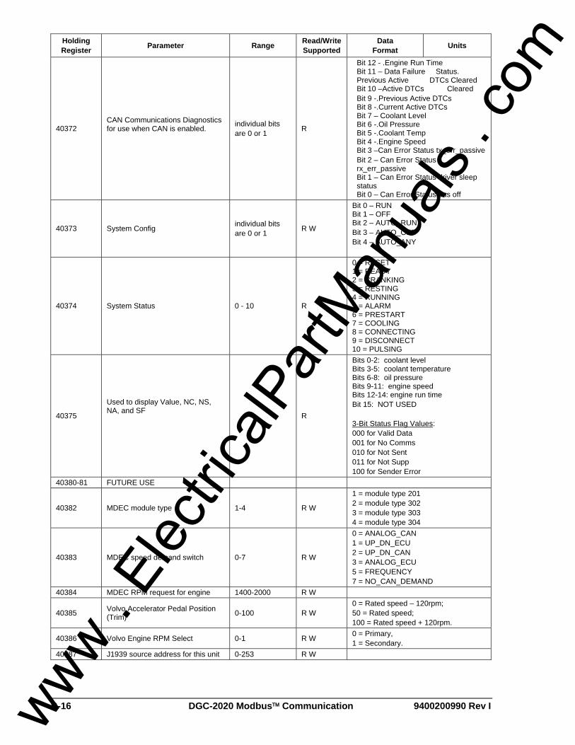
B-16 DGC-2020 Modbus™ Communication 9400200990 Rev I
Holding Register Parameter Range Read/Write
Supported Data
Format Units
40372 CAN Communications Diagnostics for use when CAN is enabled.
individual bits are 0 or 1 R
Bit 12 - .Engine Run Time Bit 11 – Data Failure Status. Previous Active DTCs Cleared Bit 10 –Active DTCs Cleared Bit 9 -.Previous Active DTCs Bit 8 -.Current Active DTCs Bit 7 – Coolant Level Bit 6 -.Oil Pressure Bit 5 -.Coolant Temp Bit 4 -.Engine Speed Bit 3 –Can Error Status tx_err_passive Bit 2 – Can Error Status rx_err_passive Bit 1 – Can Error Status driver sleep status Bit 0 – Can Error Status bus off
40373 System Config individual bits are 0 or 1 R W
Bit 0 – RUN Bit 1 – OFF Bit 2 – AUTO_RUN Bit 3 – AUTO_OFF Bit 4 – AUTO_ANY
40374 System Status 0 - 10 R
0 = RESET 1 = READY 2 = CRANKING 3 = RESTING 4 = RUNNING 5 = ALARM 6 = PRESTART 7 = COOLING 8 = CONNECTING 9 = DISCONNECT 10 = PULSING
40375
Used to display Value, NC, NS, NA, and SF
R
Bits 0-2: coolant level Bits 3-5: coolant temperature Bits 6-8: oil pressure Bits 9-11: engine speed Bits 12-14: engine run time Bit 15: NOT USED 3-Bit Status Flag Values: 000 for Valid Data 001 for No Comms 010 for Not Sent 011 for Not Supp 100 for Sender Error
40380-81 FUTURE USE
40382 MDEC module type 1-4 R W
1 = module type 201 2 = module type 302 3 = module type 303 4 = module type 304
40383 MDEC speed demand switch 0-7 R W
0 = ANALOG_CAN 1 = UP_DN_ECU 2 = UP_DN_CAN 3 = ANALOG_ECU 5 = FREQUENCY 7 = NO_CAN_DEMAND
40384 MDEC RPM request for engine 1400-2000 R W
40385 Volvo Accelerator Pedal Position (Trim) 0-100 R W
0 = Rated speed – 120rpm; 50 = Rated speed; 100 = Rated speed + 120rpm.
40386 Volvo Engine RPM Select 0-1 R W 0 = Primary, 1 = Secondary.
40387 J1939 source address for this unit 0-253 R W
www . El
ectric
alPar
tMan
uals
. com

9400200990 Rev I DGC-2020 Modbus™ Communication B-17
Holding Register Parameter Range Read/Write
Supported Data
Format Units
40388 J1939 Engine Start/Stop Configuration 0-65535 R W
0 = Not configured; 1 = Volvo Penta EDC3; 2 = MTU MDEC
40395 ECU Settling Time 0-65535 R W milliseconds
40396 ECU Pulse Cycle Time - The amount of time unit is to wait in OFF between Pulse Cycles.
0-65535 R W minutes
40397 ECU Disconnect Time - The amount of time ECU is kept powered off.
0-65535 R W seconds
40398
ECU Connect Time - The amount of time ECU is powered when connecting (unit tries to run). Also used for the Pulse duration time.
0-65535 R W seconds
40399-420 FUTURE USE J1939 DATA 40421 Accelerator Pedal Position 0 to 100% R 0.4%/bit gain, 0% offset
40422 Percent Load At Current Speed 0 to 125% R 1%/bit gain, 0% offset
40423 Actual Engine Percent Torque 0 to 125% R 1%/bit gain, -125% offset
40424 Engine Speed 0 to 8031.875 R RPM (0.125rpm/bit gain) 40425 Injection Control Pressure2 R
40426 Injector Metering Rail Pressure2 0 to +251 MPa (0 to 36 404 psi) R 1/256 MPa/bit gain, 0 MPa offset
40427 Engine Run Time 0 to +210,554, 060.75 h R 0.05 h/bit gain, 0 h offset
40428 Engine Run Time R 40429 Engine Run Time R
40430 Trip Fuel Data Range: 0 to +2,105,540, 608 L
R 0.5 L per bit gain, 0 L offset
40431 Trip Fuel R 40432 Trip Fuel R
40433 Total Fuel Used Data Range: 0 to +2,105,540, 608 L
R 0.5 L per bit gain, 0 L offset
40434 Total Fuel Used R 40435 Total Fuel Used R
40436 Coolant Temperature -40 to +210 °C (-40 to 410 °F) R 1 °C/bit gain,
40437 Fuel Temperature -40 to +210 °C (-40 to 410 °F) R 1 °C/bit gain, -40 °C offset
40438 Engine Oil Temperature -273 to +1735.0 °C (-459.4 to 3155.0 °F)
R 0.03125 °C/bit gain, -273 °C offset
40439 Engine Intercooler Temperature -40 to +210 °C (-40 to 410 °F) R 1 °C/bit gain, -40 °C offset
40440 Fuel Delivery Pressure 0 to +1000 kPa (0 to 145 psi) R 4 kPa/bit gain, 0 kPa offset
40441 Engine Oil Level 0 to +100 % R 0.4 %/bit gain, 0 % offset
40442 Oil Pressure 0 to +1000 kPa (0 to 145 psi) R 4 kPa/bit gain, 0 kPa offset
40443 Coolant Pressure 0 to +500 kPa (0 to 72.5 psi) R 4 kPa/bit gain, 0 kPa offset
40444 Coolant Level 0 to +100 % R 0.4 %/bit gain, 0 % offset
40445 Fuel Rate 0 to +3212.75 L/h R 0.05 L/h per bit gain, 0 L/h offset (13.9 x
10-6 L/s per bit)
40446 Barometric Pressure 0 to +125 kPa (0 to +18.1 psi) R 0.5 kPa/bit gain, 0 kPa offset
40447 Ambient Air Temperature -273 to +1735.0 °C (-459.4 to 3155.0 °F)
R 0.03125 °C/bit gain, -273 °C offset
www . El
ectric
alPar
tMan
uals
. com

B-18 DGC-2020 Modbus™ Communication 9400200990 Rev I
Holding Register Parameter Range Read/Write
Supported Data
Format Units
40448 Air Inlet Temperature -40 to +210 °C (-40 to 410 °F) R 1 °C/bit gain, -40 °C offset
40449 Boost Pressure 0 to +500 kPa (0 to 72.5 psi) R 2 kPa/bit gain, 0 kPa offset
40450 Intake Manifold Temperature -40 to +210 °C (-40 to 410 °F) R 1 °C/bit gain, -40 °C offset
40451 Air Filter Differential Pressure 0 to +12.5 kPa (0 to +1.8 psi) R 0.05 kPa/bit gain, 0 kPa offset
40452 Exhaust Gas Temperature -273 to +1735.0 °C (-459.4 to 3155.0 °F)
R 0.03125 °C/bit gain, -273 °C offset
40453 Electrical Potential Voltage 0 to +3212.75 V R 0.05 V/bit gain, 0 V offset
40454 Battery Potential Voltage Switched Data Range: 0 to +3212.75 V R 0.05 V/bit gain, 0 V offset
40455 Speed At Idle Point1 0 to 8031.875 rpm R 0.125 rpm/bit, 0 rpm offset
40456 Torque At Idle Point1 0 to 125% R 1%/bit gain, -125% offset
40457 Speed At Idle Point2 0 to 8031.875 rpm R 0.125 rpm/bit, 0 rpm offset
40458 Torque At Idle Point2 0 to 125% R 1%/bit gain, -125% offset
40459 Speed At Idle Point3 0 to 8031.875 rpm R 0.125 rpm/bit, 0 rpm offset
40460 Torque At Idle Point3 0 to 125% R 1%/bit gain, -125% offset
40461 Speed At Idle Point4 0 to 8031.875 rpm R 0.125 rpm/bit, 0 rpm offset
40462 Torque At Idle Point4 0 to 125% R 1%/bit gain, -125% offset
40463 Speed At Idle Point5 0 to 8031.875 rpm R 0.125 rpm/bit, 0 rpm offset
40464 Torque At Idle Point5 0 to 125% R 1%/bit gain, -125% offset
40465 Speed At High Idle Point6 0 to 8031.875 rpm R 0.125 rpm/bit, 0 rpm offset
40466 Gain Of End speed governor 0 to 50.2 %/rpm R
0.0007813 % engine reference torque/rpm per bit gain (normalized), 0 %/rpm per bit offset
40467 Reference Engine Torque 0 to 64 255 Nm R 1 Nm/bit gain, 0 Nm offset
40468 Override Speed Point7 0 to 8031.875 rpm R 0.125 rpm/bit, 0 rpm offset
40469 Override Time Limit 0 s to 25 s R 0.1 s/bit gain, 0 s offset 40470 Speed Lower Limit 0 to 2500 rpm R 10 rpm/bit gain, 0 rpm offset 40471 Speed Upper Limit 0 to 2500 rpm R 10 rpm/bit gain, 0 rpm offset 40472 Torque Lower Limit 0 to 125% R 1%/bit gain, -125% offset 40473 Torque Upper Limit 0 to 125% R 1%/bit gain, -125% offset
40474 Crankcase Pressure -250 to +251.99 kPa R 0.0078125 kPa/bit gain,
-250 kPa offset 40475 Oil Filter Diff. Pressure 0 to 125 kPa R 0.5 kPa/bit gain, 0 offset 40476 Fuel Filter Diff. Pressure 0 to 500 kPa R 2 kPa/bit gain, 0 offset 40477-82 FUTURE USE 40493-99 FUTURE USE
40500 DGC-2020 product series identifier 2020 R
40501
Firmware Part Number - 2nd most significant digit. NOTE: The most significant digit is always 9, but is not mapped.
0 - 9 R
40502 Firmware Part Number - 3rd-6th most significant digits
0000 - 9999 R
40503 Firmware Part Number - four least significant digits 0000 - 9999 R
www . El
ectric
alPar
tMan
uals
. com

9400200990 Rev I DGC-2020 Modbus™ Communication B-19
Holding Register Parameter Range Read/Write
Supported Data
Format Units
40504 LED Status individual bits are 0 or 1 R
Bits indicate status of LED’s: b0 = RUN b1 = OFF b2 = AUTO b3 = ALARM b4 = LOAD b5 = NOT IN AUTO
40507 Read Relay Image of both Main and Aux Output (Duplicate of 40298)
individual bits are 0 or 1 R
Main is in lower byte and Aux is in upper byte. b0 = Aux Output 1, b1 = Aux Output 2, b2 = Aux Output 3, b3 = Aux Output 4, b4 = Aux Output 5, b5 = Aux Output 6, b6 = Aux Output 7, b7 = Aux Output 8. b8 = Master Start Relay, b9 = Fuel Solenoid Relay, b10 = PreHeat PreLube Relay, b11 = Alarm Relay, b12 = UNASSIGNED, b13 = Buzzer On, b14 = EPS Loaded Relay, b15 = PreAlarm Relay,
40508 Input Contacts States (Duplicate of 40273)
individual bits are 0 or 1 R
b0 = coolant level, b1 = ATS, b2 = E-stop, b3 = charger failed, b4 = aux. input 1, b5 = aux. input 2, b6 = aux. input 3, b7 = aux. input 4. /* b7 = aux. input 4. */
40509-604 RESERVED OVERCURRENT
40605 51 Pick-up – 3-phase 18-118, 90-775 R W 0.18-1.18 Aac for 1A CTs,
0.90-7.75 Aac for 5A CTs
40606 51 Time Dial – 3-phase 0-99, 0-300 R W 0.0-9.9 for 40607=0-15 (inverse),
0.0-30.0s for 40607=16 (fixed) 40607 51 Curve – 3-phase 0-16 R W 0-15 for inverse, 16 for fixed 40608 51 Alarm Config. – 3-phase 0-2 R W 0=None, 1=Pre-Alarm, 2=Alarm
40609 51 Pick-up – 1-phase 18-118, 90-775 R W 0.18-1.18 Aac for 1A CTs,
0.90-7.75 Aac for 5A CTs
40610 51 Time Dial – 1-phase 0-99, 0-300 R W 0.0-9.9 for 40607=0-15 (inverse),
0.0-30.0s for 40607=16 (fixed) 40611 51 Curve – 1-phase 0-16 R W 0-15 for inverse, 16 for fixed 40612 51 Alarm Config. – 1-phase 0-2 R W 0=None, 1=Pre-Alarm, 2=Alarm PHASE IMBALANCE 40613 47 Pick-up 5-100 R W Volts AC 40614 47 Time Delay 0-300 R W 0.0-30.0 seconds 40615 47 Alarm Configuration 0-2 R W 0=None, 1=Pre-Alarm, 2=Alarm UNDERVOLTAGE 40616 27 Pick-up – 3-phase 70-576 R W Volts AC 40617 27 Time Delay – 3-phase 0-300 R W 0.0-30.0 seconds 40618 27 Inhibit Frequency- 3-ph. 20-400 R W Hertz 40619 27 Alarm Config. – 3-phase 0-2 R W 0=None, 1=Pre-Alarm, 2=Alarm 40620 27 Pick-up – 1-phase 70-576 R W Volts AC 40621 27 Time Delay – 1-phase 0-300 R W 0.0-30.0 seconds 40622 27 Inhibit Frequency – 1-ph. 20-400 R W Hertz 40623 27 Alarm Config. – 1-phase 0-2 R W 0=None, 1=Pre-Alarm, 2=Alarm
www . El
ectric
alPar
tMan
uals
. com

B-20 DGC-2020 Modbus™ Communication 9400200990 Rev I
Holding Register Parameter Range Read/Write
Supported Data
Format Units
OVERVOLTAGE 40624 59 Pick-up – 3-phase 70-576 R W Volts AC 40625 59 Time Delay – 3-phase 0-300 R W 0.0-30.0 seconds 40626 59 Alarm Config. – 3-phase 0-2 R W 0=None, 1=Pre-Alarm, 2=Alarm 40627 59 Pick-up – 1-phase 70-576 R W Volts AC 40628 59 Time Delay – 1-phase 0-300 R W 0.0-30.0 seconds 40629 59 Alarm Config. – 1-phase 0-2 R W 0=None, 1=Pre-Alarm, 2=Alarm UNDERFREQUENCY
40630 81U Pick-up 450-550, 550-650, 3600-4400
R W 45.0-55.0 Hz for 50-Hz config., 55.0-65.0 Hz for 60-Hz config., 360.0-440.0 Hz for 400-Hz unit
40631 81U Time Delay 0-300 R W 0.0-30.0 seconds 40632 81U Inhibit Voltage 70-576 R W Volts AC 40633 81U Alarm Configuration 0-2 R W 0=None, 1=Pre-Alarm, 2=Alarm OVERFREQUENCY
40634 81O Pick-up 450-550, 550-650, 3600-4400
R W 45.0-55.0 Hz for 50-Hz config., 55.0-65.0 Hz for 60-Hz config., 360.0-440.0 Hz for 400-Hz unit
40635 81O Time Delay 0-300 R W 0.0-30.0 seconds 40636 81O Alarm Configuration 0-2 R W 0=None, 1=Pre-Alarm, 2=Alarm GENERATOR PROTECTION STATUS
40637 Gen Protection Status (upper 16 bits) 0-65535 R b16-b31 UNASSIGNED
40638 Gen Protection Status (lower 16 bits) 0-65535 R
b0 = overvoltage trip, b1 = undervoltage trip, b2 = overfrequency trip, b3 = underfrequency trip, b4 = overcurrent trip, b5 = phase imbalance trip, b6-b15 UNASSIGNED
40639 Gen Protection Pre-Alarms (upper 16 bits) 0-65535 R b16-b31 UNASSIGNED
40640 Gen Protection Pre-Alarms (lower 16 bits) 0-65535 R
b0 = overvoltage pre-alarm, b1 = undervoltage pre-alarm, b2 = overfrequency pre-alarm, b3 = underfrequency pre-alarm, b4 = overcurrent pre-alarm, b5 = phase imbalance pre-alarm, b6-b15 UNASSIGNED
40641 Gen Protection Alarms (upper 16 bits) 0-65535 R b16-b31 UNASSIGNED
40642 Gen Protection Alarms (lower 16 bits) 0-65535 R
b0 = overvoltage alarm, b1 = undervoltage alarm, b2 = overfrequency alarm, b3 = underfrequencyalarm, b4 = overcurrent alarm, b5 = phase imbalance alarm, b6-b15 UNASSIGNED
REAL TIME CLOCK 40700 Hours 0-23 R W 40701 Minutes 0-59 R W 40702 Seconds 0-59 R W 40703 Month 1-12 R W 40704 Day 1-31 R W 40705 Year R W
40706 Daylight Savings Time Enable 0-1 R W 0 = Off 1 = On
40707-33 RESERVED RUN STATISTICS 40734 Maintenance Interval Hours 0-5000 R W hours 40735 Hours Until Maintenance 0-5000 R W hours
www . El
ectric
alPar
tMan
uals
. com

9400200990 Rev I DGC-2020 Modbus™ Communication B-21
Holding Register Parameter Range Read/Write
Supported Data
Format Units
40737 Commission Start Month 1-12 R W month 40738 Commission Start Day 1-31 R W day 40739 Commission Start Year 0-99 R W year 40740-41 Cumulative Run Hours x 60 0-4294967295 R W DP hours
40742-43 Cumulative Loaded Run Hours x 60 0-4294967295 R W DP hours
40744-45 Cumulative Unloaded Run Hours x 60 0-4294967295 R W DP hours
40746 Start Count 0-65535 R W 40747 Session Start Month 1-12 R W month 40748 Session Start Day 1-31 R W day 40749 Session Start Year 0-99 R W year 40750-51 Session Run Hours x 60 0-4294967295 R W DP hours 40752-53 Session Loaded Run Hours x 60 0-4294967295 R W DP hours 40754-55 Session Unloaded Run Hours x 60 0-4294967295 R W DP hours Canbus ECU
40758 ECU Control Output Select 0-1 R W 0 = fuel solenoid relay, 1 = pre-start relay
40759 ECU Pulsing Enable 0-1 R W 0 = pulsing is enabled, 1 = pulsing is disabled
40760 MDEC Alarms 0-65535 R
b0 = High Charge Air Temp, b1 = High Oil Temp, b2 = High Coolant Temp, b3 = Low Aftercooler Level, b4 = Low Fuel Delivery Press, b5 = Low Oil Press, b6 = Overspeed, b7 = Combined Red, b8-b15 UNASSIGNED
40761 MDEC Pre-alarms 0-65535 R
b0 = High ECU Temp, b1 = High Oil Temp, b2 = High Intercooler Temp, b3 = High Charge Air Temp, b4 = High Coolant Temp, b5 = Shutdown Override, b6 = High Fuel Rail Press, b7 = Low Fuel Rail Press, b8 = Low Coolant Level, b9 = Low Charge Air Pressure, b10 = Low Fuel Deliv Pressure, b11 = Low Oil Pressure, b12 = Combined Yellow, b13-b15 UNASSIGNED
Current Parameter Table The DGC-2020 maps all non-legacy parameters into the Holding Register address space (42000 and above). Query address N will access the Holding Register N+1. Data Format is Long Integer type data unless identified otherwise in the Data Format column. See Table B-4.
Table B-4. Current Parameter Table Holding Register Parameter Range Read/Write
Supported Data Format Units
BREAKER MANAGEMENT
42000 Gen Breaker Configured 0-1 R 0 = NOT Configured, 1 = Configured
42002 Gen Breaker Open Pulse Time 1-80 R W milliseconds * 10 42004 Gen Breaker Close Pulse Time 1-80 R W milliseconds * 10
42006 Gen Breaker Contact Type 0-1 R W 0 = Pulse, 1 = Continuous
42008 Gen Breaker Close Time 0-800 R W milliseconds in increments of 5
www . El
ectric
alPar
tMan
uals
. com
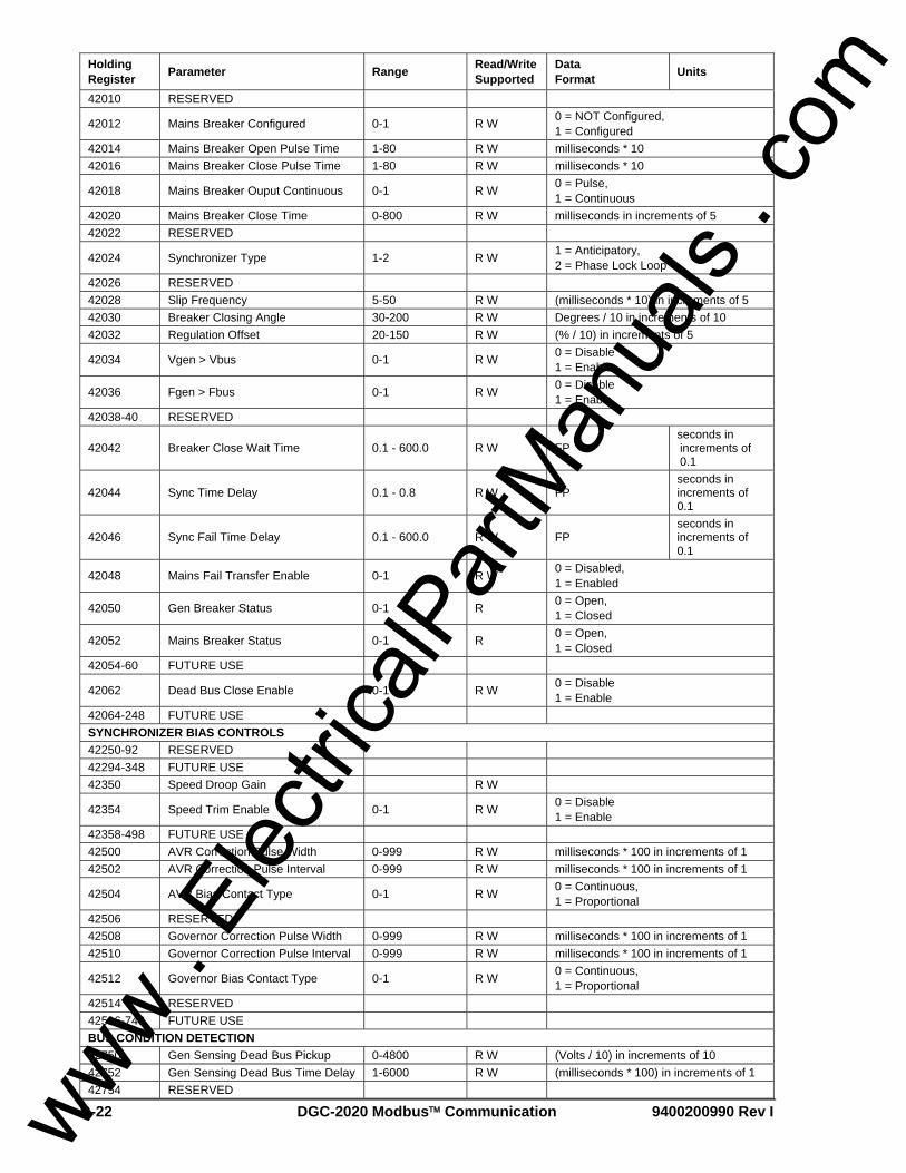
B-22 DGC-2020 Modbus™ Communication 9400200990 Rev I
Holding Register Parameter Range Read/Write
Supported Data Format Units
42010 RESERVED
42012 Mains Breaker Configured 0-1 R W 0 = NOT Configured, 1 = Configured
42014 Mains Breaker Open Pulse Time 1-80 R W milliseconds * 10 42016 Mains Breaker Close Pulse Time 1-80 R W milliseconds * 10
42018 Mains Breaker Ouput Continuous 0-1 R W 0 = Pulse, 1 = Continuous
42020 Mains Breaker Close Time 0-800 R W milliseconds in increments of 5 42022 RESERVED
42024 Synchronizer Type 1-2 R W 1 = Anticipatory, 2 = Phase Lock Loop
42026 RESERVED 42028 Slip Frequency 5-50 R W (milliseconds * 10) in increments of 5 42030 Breaker Closing Angle 30-200 R W Degrees / 10 in increments of 10 42032 Regulation Offset 20-150 R W (% / 10) in increments of 5
42034 Vgen > Vbus 0-1 R W 0 = Disable 1 = Enable
42036 Fgen > Fbus 0-1 R W 0 = Disable 1 = Enable
42038-40 RESERVED
42042 Breaker Close Wait Time 0.1 - 600.0 R W FP seconds in increments of 0.1
42044 Sync Time Delay 0.1 - 0.8 R W FP seconds in increments of 0.1
42046 Sync Fail Time Delay 0.1 - 600.0 R W FP seconds in increments of 0.1
42048 Mains Fail Transfer Enable 0-1 R W 0 = Disabled, 1 = Enabled
42050 Gen Breaker Status 0-1 R 0 = Open, 1 = Closed
42052 Mains Breaker Status 0-1 R 0 = Open, 1 = Closed
42054-60 FUTURE USE
42062 Dead Bus Close Enable 0-1 R W 0 = Disable 1 = Enable
42064-248 FUTURE USE SYNCHRONIZER BIAS CONTROLS 42250-92 RESERVED 42294-348 FUTURE USE 42350 Speed Droop Gain R W
42354 Speed Trim Enable 0-1 R W 0 = Disable 1 = Enable
42358-498 FUTURE USE 42500 AVR Correction Pulse Width 0-999 R W milliseconds * 100 in increments of 1 42502 AVR Correction Pulse Interval 0-999 R W milliseconds * 100 in increments of 1
42504 AVR Bias Contact Type 0-1 R W 0 = Continuous, 1 = Proportional
42506 RESERVED 42508 Governor Correction Pulse Width 0-999 R W milliseconds * 100 in increments of 1 42510 Governor Correction Pulse Interval 0-999 R W milliseconds * 100 in increments of 1
42512 Governor Bias Contact Type 0-1 R W 0 = Continuous, 1 = Proportional
42514 RESERVED 42516-748 FUTURE USE BUS CONDITION DETECTION 42750 Gen Sensing Dead Bus Pickup 0-4800 R W (Volts / 10) in increments of 10 42752 Gen Sensing Dead Bus Time Delay 1-6000 R W (milliseconds * 100) in increments of 1 42754 RESERVED
www . El
ectric
alPar
tMan
uals
. com

9400200990 Rev I DGC-2020 Modbus™ Communication B-23
Holding Register Parameter Range Read/Write
Supported Data Format Units
42756 Gen Sensing Stable Undervoltage Pickup 100-12000 R W (Volts / 10) in increments of 10
42758 Gen Sensing Stable Undervoltage Dropout 100-12000 R W (Volts / 10) in increments of 10
42760 Gen Sensing Stable Overvoltage Pickup 100-12000 R W (Volts / 10) in increments of 10
42762 Gen Sensing Stable Overvoltage Dropout 100-12000 R W (Volts / 10) in increments of 10
42764 Gen Sensing Stable Underfrequency Pickup 4600-6400 R W (Hz / 100) in increments of 5
42766 Gen Sensing Stable Underfrequency Dropout 4600-6400 R W (Hz / 100) in increments of 5
42768 Gen Sensing Stable Overfrequency Pickup 4600-6400 R W (Hz / 100) in increments of 5
42770 Gen Sensing Stable Overfrequency Dropout 4600-6400 R W (Hz / 100) in increments of 5
42772 Gen Sensing Fail Time Delay 1-6000 R W (milliseconds * 100) in increments of 1 42774 Gen Sensing Stable Time Delay 1-6000 R W (milliseconds * 100) in increments of 1 42776 RESERVED 42778 Bus Sensing Dead Bus Pickup 0-4800 R W (Volts / 10) in increments of 10 42780 Bus Sensing Dead Bus Time Delay 1-6000 R W (milliseconds * 100) in increments of 1 42782 RESERVED
42784 Bus Sensing Stable Undervoltage Pickup 100-12000 R W (Volts / 10) in increments of 10
42786 Bus Sensing Stable Undervoltage Dropout 100-12000 R W (Volts / 10) in increments of 10
42788 Bus Sensing Stable Overvoltage Pickup 100-12000 R W (Volts / 10) in increments of 10
42790 Bus Sensing Stable Overvoltage Dropout 100-12000 R W (Volts / 10) in increments of 10
42792 Bus Sensing Stable Underfrequency Pickup 4600-6400 R W (Hz / 100) in increments of 5
42794 Bus Sensing Stable Underfrequency Dropout 4600-6400 R W (Hz / 100) in increments of 5
42796 Bus Sensing Stable Overfrequency Pickup 4600-6400 R W (Hz / 100) in increments of 5
42798 Bus Sensing Stable Overfrequency Dropout 4600-6400 R W (Hz / 100) in increments of 5
42800 Bus Sensing Fail Time Delay 1-6000 R W (milliseconds * 100) in increments of 1 42802 Bus Sensing Stable Time Delay 1-6000 R W (milliseconds * 100) in increments of 1 42804 RESERVED 42806-3432 FUTURE USE SENDERS
43434 Coolant Temperature Sender Fail Configuration Type -1, 0, 1 R W
0 = None 1 = Alarm 2 = Pre-Alarm
43436 Coolant Temperature Sender Fail Activation Delay 50-300 R W Minutes in increments of 5
43438 Oil Pressure Sender Fail Configuration Type -1, 0, 1 R W
0 = None 1 = Alarm 2 = Pre-Alarm
43440 Oil Pressure Sender Fail Activation Delay 0-300 R W Seconds in increments of 1
43442 Fuel Level Sender Fail Configuration Type -1, 0, 1 R W
0 = None 1 = Alarm 2 = Pre-Alarm
43444 Fuel Level Sender Fail Activation Delay 0-300 R W Seconds in increments of 1
43446 Voltage Sensing Fail Configuration Type -1, 0, 1 R W
0 = None 1 = Alarm 2 = Pre-Alarm
43448 Voltage Sensing Fail Activation Delay 0-300 R W Seconds in increments of 1
www . El
ectric
alPar
tMan
uals
. com

B-24 DGC-2020 Modbus™ Communication 9400200990 Rev I
Holding Register Parameter Range Read/Write
Supported Data Format Units
43450-498 FUTURE USE SYSTEM CONFIGURATION AND STATUS 43500 Rated Volts 1-999 R W Volts in increments of 1
43502 Pre-Start Contact Config 0-1 R W 0 = Open After Disconnect 1 = Closed While Running
43504 System Units 0-1 R W 0 = English 1 = Metric
43506 Battery Volts 0-1 R W 0 = 12V 1 = 24V
43508 Off Mode Status 0-1 R 0 = Disable 1 = Enable
43510 Run Mode Status 0-1 R 0 = Disable 1 = Enable
43512 Auto Mode Status 0-1 R 0 = Disable 1 = Enable
43514 Virtual Input 1 Status 0-1 R 0 = Disable 1 = Enable
43516 Virtual Input 2 Status 0-1 R 0 = Disable 1 = Enable
43518 Virtual Input 3 Status 0-1 R 0 = Disable 1 = Enable
43520 Virtual Input 4 Status 0-1 R 0 = Disable 1 = Enable
43624 EPS Low Line Scale Factor 0-3 R W Increments of 0.001 43626 Rated Power Factor -1 to 1 R W Increments of 0.001
43628 Prestart Rest Configuration 0-2 R W 0 = Off During Rest 1 = On During Rest 2 = Preheat before Crank
43630 Oil Pressure Crank Disconnect 0-1 R W 0 = Disable 1 = Enable
43632 Crank Disconnect Pressure 3-150 R W Increments of 1 43634 Crank Disconnect Pressure in KPA 21-1034 R W Increments of 1 43636-748 FUTURE USE CONTROL
43750 Emergency Stop 0-1 R W A value of 1 will invoke the Emergency Stop
43752 Remote Start 0-1 R W A value of 1 will invoke the Remote Start
43754 Remote Stop 0-1 R W A value of 1 will invoke the Remote Stop
43756 Run Mode 0-1 R W A value of 1 will invoke the Run Mode 43758 Off Mode 0-1 R W A value of 1 will invoke the Off Mode 43760 Auto Mode 0-1 R W A value of 1 will invoke the Auto Mode 43762 RESERVED 43764 Gen Breaker Open 0-1 R W A value of 1 will open the Gen Breaker 43766 Gen Breaker Close 0-1 R W A value of 1 will close the Gen Breaker 43768 Mains Breaker Open 0-1 R W A value of 1 will open the Mains 43770 Mains Breaker Close 0-1 R W A value of 1 will close the Mains 43772 RESERVED
43774 Virtual Input 1 Close 0-1 R W A value of 1 will close the Virtual Input 1 Switch
43776 Virtual Input 1 Open 0-1 R W A value of 1 will open the Virtual Input 1 Switch
43778 Virtual Input 2 Close 0-1 R W A value of 1 will close the Virtual Input 2 Switch
43780 Virtual Input 2 Open 0-1 R W A value of 1 will open the Virtual Input 2 Switch
43782 Virtual Input 3 Close 0-1 R W A value of 1 will close the Virtual Input 3 Switch
43784 Virtual Input 3 Open 0-1 R W A value of 1 will open the Virtual Input 3 Switch
www . El
ectric
alPar
tMan
uals
. com

9400200990 Rev I DGC-2020 Modbus™ Communication B-25
Holding Register Parameter Range Read/Write
Supported Data Format Units
43786 Virtual Input 4 Close 0-1 R W A value of 1 will close the Virtual Input 4 Switch
43788 Virtual Input 4 Open 0-1 R W A value of 1 will open the Virtual Input 4 Switch
43790-998 FUTURE USE
PROTECTION 44000-34 RESERVED 44036-48 FUTURE USE
44050 DHCP Enabled 0-1 R 0 = Disabled 1 = Enabled
44052 Active IP Address R 44054 Gateway IP Address R 44056 Subnet Mask R 44058-248 FUTURE USE
44250 3 Phase Overcurrent Pickup (51-1) 18-118 1A 90-7750 5A R W (Sec Amps / 100) in increments of 1
44252 3 Phase Overcurrent Time Dial (51-1) 0-99 R W (Units / 10) in increments of 1
44254 3 Phase Overcurrent Curve (51-1) 0-16 R W
0 = S1 Curve 1 = S2 Curve 2 = L1 Curve 3 = L2 Curve 4 = D Curve 5 = M Curve 6 = I1 Curve 7 = I2 Curve 8 = V1 Curve 9 = V2 Curve 10 = E1 Curve 11 = E2 Curve 12 = A Curve 13 = B Curve 14 = C Curve 15 = G Curve 16 = F Curve
44256 3 Phase Overcurrent Alarm Configuration (51-1) 0-2 R W
0 = None 1 = Alarm 2 = Pre-Alarm
44258 1 Phase Overcurrent Pickup (51-1) 18-118 1A 90-7750 5A R W (Sec Amps / 100) in increments of 1
44260 1 Phase Overcurrent Time Dial (51-1) 0-99 R W (Units / 10) in increments of 1
44262 1 Phase Overcurrent Curve (51-1) 0-16 R W
0 = S1 Curve 1 = S2 Curve 2 = L1 Curve 3 = L2 Curve 4 = D Curve 5 = M Curve 6 = I1 Curve 7 = I2 Curve 8 = V1 Curve 9 = V2 Curve 10 = E1 Curve 11 = E2 Curve 12 = A Curve 13 = B Curve 14 = C Curve 15 = G Curve 16 = F Curve
44264 1 Phase Overcurrent Alarm Configuration (51-1) 0-2 R W
0 = None 1 = Alarm 2 = Pre-Alarm
44266 Phase Imbalance Pickup 5-100 R W Volts in increments of 1
www . El
ectric
alPar
tMan
uals
. com

B-26 DGC-2020 Modbus™ Communication 9400200990 Rev I
Holding Register Parameter Range Read/Write
Supported Data Format Units
44268 Phase Imbalance Activation Delay 0-300 R W (Seconds / 10) in increments of 1
44270 Phase Imbalance Alarm Configuration 0-2 R W
0 = None 1 = Alarm 2 = Pre-Alarm
44272 3 Phase Undervoltage Pickup (27-1) 70-576 R W Volts in increments of 1
44274 3 Phase Undervoltage Activation Delay (27-1) 0-300 R W (Seconds / 10) in increments of 1
44276 3 Phase Undervoltage Inhibit Frequency (27-1) 20-400 R W Hz in increments of 1
44278 3 Phase Undervoltage Alarm Configuration (27-1) 0-2 R W
0 = None 1 = Alarm 2 = Pre-Alarm
44280 1 Phase Undervoltage Pickup (27-1) 70-576 R W Volts in increments of 1
44282 1 Phase Undervoltage Activation Delay (27-1) 0-300 R W (Seconds / 10) in increments of 1
44284 1 Phase Undervoltage Inhibit Frequency (27-1) 20-400 R W Hz in increments of 1
44286 1 Phase Undervoltage Alarm Configuration (27-1) 0-2 R W
0 = None 1 = Alarm 2 = Pre-Alarm
44288 3 Phase Overvoltage Pickup (59-1) 70-576 R W Volts in increments of 1
44290 3 Phase Overvoltage Activation Delay (59-1) 0-300 R W (Seconds / 10) in increments of 1
44292 3 Phase Overvoltage Alarm Configuration (59-1) 0-2 R W
0 = None 1 = Alarm 2 = Pre-Alarm
44294 1 Phase Overvoltage Pickup (59-1) 70-576 R W Volts in increments of 1
44296 1 Phase Overvoltage Activation Delay (59-1) 0-300 R W (Seconds / 10) in increments of 1
44298 1 Phase Overvoltage Alarm Configuration (59-1) 0-2 R W
0 = None 1 = Alarm 2 = Pre-Alarm
44300 Underfrequency Pickup
450-550 50Hz 540-660 60Hz 3600-4400 400Hz
R W (Hz / 10) in increments of 1
44302 Underfrequency Activation Delay 0-300 R W (Seconds / 10) in increments of 1 44304 Underfrequency Inhibit Voltage 70-576 R W Volts in increments of 1
44306 Underfrequency Alarm Configuration 0-2 R W
0 = None 1 = Alarm 2 = Pre-Alarm
44308 Overfrequency Pickup
450-550 50Hz 540-660 60Hz 3600-4400 400Hz
R W (Hz / 10) in increments of 1
44310 Overfrequency Activation Delay 0-300 R W (Seconds / 10) in increments of 1
44312 Overfrequency Alarm Configuration 0-2 R W 0 = None 1 = Alarm 2 = Pre-Alarm
44314 Overcurrent Low Line Scale Factor (51-1) 0.000 - 3.000 R W FP In increments of
0.001
44316 Overvoltage Low Line Scale Factor (59-1) 0.000 - 3.000 R W FP In increments of
0.001
44318 Undervoltage Low Line Scale Factor (27-1) 0.000 - 3.000 R W FP In increments of
0.001
44320 3 Phase Overcurrent Pickup (51-2) 18-118 1A 90-7750 5A R W (Sec Amps / 100) in increments of 1
44322 3 Phase Overcurrent Time Dial (51-2) 0-99 R W (Units / 10) in increments of 1
www . El
ectric
alPar
tMan
uals
. com

9400200990 Rev I DGC-2020 Modbus™ Communication B-27
Holding Register Parameter Range Read/Write
Supported Data Format Units
44324 3 Phase Overcurrent Curve (51-2) 0-16 R W
0 = S1 Curve 1 = S2 Curve 2 = L1 Curve 3 = L2 Curve 4 = D Curve 5 = M Curve 6 = I1 Curve 7 = I2 Curve 8 = V1 Curve 9 = V2 Curve 10 = E1 Curve 11 = E2 Curve 12 = A Curve 13 = B Curve 14 = C Curve 15 = G Curve 16 = F Curve
44326 3 Phase Overcurrent Alarm Configuration (51-2) 0-2 R W
0 = None 1 = Alarm 2 = Pre-Alarm
44328 1 Phase Overcurrent Pickup (51-2) 18-118 1A 90-7750 5A R W (Sec Amps / 100) in increments of 1
44330 1 Phase Overcurrent Time Dial (51-2) 0-99 R W (Units / 10) in increments of 1
44332 1 Phase Overcurrent Curve (51-2) 0-16 R W
0 = S1 Curve 1 = S2 Curve 2 = L1 Curve 3 = L2 Curve 4 = D Curve 5 = M Curve 6 = I1 Curve 7 = I2 Curve 8 = V1 Curve 9 = V2 Curve 10 = E1 Curve 11 = E2 Curve 12 = A Curve 13 = B Curve 14 = C Curve 15 = G Curve 16 = F Curve
44334 1 Phase Overcurrent Alarm Configuration (51-2) 0-2 R W
0 = None 1 = Alarm 2 = Pre-Alarm
44336 3 Phase Undervoltage Pickup (27-2) 70-576 R W Volts in increments of 1
44338 3 Phase Undervoltage Activation Delay (27-2) 0-300 R W (Seconds / 10) in increments of 1
44340 3 Phase Undervoltage Inhibit Frequency (27-2) 20-400 R W Hz in increments of 1
44342 3 Phase Undervoltage Alarm Configuration (27-2) 0-2 R W
0 = None 1 = Alarm 2 = Pre-Alarm
44344 1 Phase Undervoltage Pickup (27-2) 70-576 R W Volts in increments of 1
44346 1 Phase Undervoltage Activation Delay (27-2) 0-300 R W (Seconds / 10) in increments of 1
44348 1 Phase Undervoltage Inhibit Frequency (27-2) 20-400 R W Hz in increments of 1
44350 1 Phase Undervoltage Alarm Configuration (27-2) 0-2 R W
0 = None 1 = Alarm 2 = Pre-Alarm
44352 3 Phase Overvoltage Pickup (59-2) 70-576 R W Volts in increments of 1
44354 3 Phase Overvoltage Activation Delay (59-2) 0-300 R W (Seconds / 10) in increments of 1
www . El
ectric
alPar
tMan
uals
. com

B-28 DGC-2020 Modbus™ Communication 9400200990 Rev I
Holding Register Parameter Range Read/Write
Supported Data Format Units
44356 3 Phase Overvoltage Alarm Configuration (59-2) 0-2 R W
0 = None 1 = Alarm 2 = Pre-Alarm
44358 1 Phase Overvoltage Pickup (59-2) 70-576 R W Volts in increments of 1
44360 1 Phase Overvoltage Activation Delay (59-2) 0-300 R W (Seconds / 10) in increments of 1
44362 1 Phase Overvoltage Alarm Configuration (59-2) 0-2 R W
0 = None 1 = Alarm 2 = Pre-Alarm
44364 Overcurrent Low Line Scale Factor (51-2) 0.000 - 3.000 R W FP In increments of
0.001
44366 Overvoltage Low Line Scale Factor (59-2) 0.000 - 3.000 R W FP In increments of
0.001
44368 Undervoltage Low Line Scale Factor (27-2) 0.000 - 3.000 R W FP In increments of
0.001 44370 Phase Imbalance Hysteresis 1-5 R W Volts in increments of 1
44372 3 Phase Undervoltage Hysteresis (27-1) 1-60 R W Volts in increments of 1
44374 1 Phase Undervoltage Hysteresis (27-1) 1-60 R W Volts in increments of 1
44376 3 Phase Overvoltage Hysteresis (59-1) 1-60 R W Volts in increments of 1
44378 1 Phase Overvoltage Hysteresis (59-1) 1-60 R W Volts in increments of 1
44380 Underfrequency Hysteresis 1-400 R W Deci-hertz in increments of 1 44382 Overfrequency Hysteresis 1-400 R W Deci-hertz in increments of 1
44384 3 Phase Undervoltage Hysteresis (27-2) 1-60 R W Volts in increments of 1
44386 1 Phase Undervoltage Hysteresis (27-2) 1-60 R W Volts in increments of 1
44388 3 Phase Overvoltage Hysteresis (59-2) 1-60 R W Volts in increments of 1
44390 1 Phase Overvoltage Hysteresis (59-2) 1-60 R W Volts in increments of 1
44392 3 Phase Reverse Power Pickup -500 to 50 R W Deci-percent in increments of 1
44394 3 Phase Reverse Power Activation Delay 0-300 R W Deci-second in increments of 1
44396 3 Phase Reverse Power Alarm Configuration 0-2 R W
0 = None 1 = Alarm 2 = Pre-Alarm
44398 3 Phase Reverse Power Hysteresis 10-100 R W Deci-percent in increments of 1 44400 1 Phase Reverse Power Pickup -500 to 50 R W Deci-percent in increments of 1
44402 1 Phase Reverse Power Activation Delay 0-300 R W Deci-second in increments of 1
44404 1 Phase Reverse Power Alarm Configuration 0-2 R W
0 = None 1 = Alarm 2 = Pre-Alarm
44406 1 Phase Reverse Power Hysteresis 10-100 R W Deci-percent in increments of 1 44408 3 Phase Loss of Excitation Pickup -1500 to 0 R W Deci-percent in increments of 1
44410 3 Phase Loss of Excitation Activation Delay 0-300 R W Deci-second in increments of 1
44412 3 Phase Loss of Excitation Alarm Configuration 0-2 R W
0 = None 1 = Alarm 2 = Pre-Alarm
44414 3 Phase Loss of Excitation Hysteresis 10-100 R W Deci-percent in increments of 1
44416 1 Phase Loss of Excitation Pickup -1500 to 0 R W Deci-percent in increments of 1
44418 1 Phase Loss of Excitation Activation Delay 0-300 R W Deci-second in increments of 1
44420 1 Phase Loss of Excitation Alarm Configuration 0-2 R W
0 = None 1 = Alarm 2 = Pre-Alarm
www . El
ectric
alPar
tMan
uals
. com

9400200990 Rev I DGC-2020 Modbus™ Communication B-29
Holding Register Parameter Range Read/Write
Supported Data Format Units
44422 1 Phase Loss of Excitation Hysteresis 10-100 R W Deci-percent in increments of 1
44424-498 FUTURE USE ALARMS
44500 High Coolant Temp Alarm Enable 0-1 R W 0 = Disable 1 = Enable
44502 High Coolant Temp Alarm Threshold 100-280 R W °F in increments of 1
44504 Metric High Coolant Temp Alarm Threshold 37-137 R W °C in increments of 1
44506 High Coolant Temp Alarm Activation Delay 50-150 RW Seconds in increments of 1
44508 Low Oil Press. Alarm Enable 0-1 R W 0 = Disable 1 = Enable
44510 Low Oil Press. Alarm Threshold 3-150 R W psi in increments of 1
44512 Metric Low Oil Press. Alarm Threshold 25-1030 R W kPa in increments of 1
44514 Low Oil Press. Alarm Arming Delay 5-15 R W Seconds in increments of 1
44516 Overspeed Alarm Enable 0-1 R W 0 = Disable 1 = Enable
44518 Overspeed Alarm Threshold 105-140 R W % in increments of 1 44520 Overspeed Alarm Activation Delay 0-500 R W Milliseconds in increments of 1
44522 Low Fuel Level Alarm Enable 0-1 R W 0 = Disable 1 = Enable
44524 Low Fuel Level Alarm Threshold 0-100 R W % in increments of 1
44526 Low Fuel Level Alarm Activation Delay 0-30 R W Seconds in increments of 1
44528 High Coolant Temp Pre-Alarm Enable 0-1 R W 0 = Disable
1 = Enable
44530 High Coolant Temp Pre-Alarm Threshold 100-280 R W °F in increments of 1
44532 Metric High Coolant Temp Pre-Alarm Threshold 37-137 R W °C in increments of 1
44534 Low Coolant Temp Pre-Alarm Enable 0-1 R W 0 = Disable
1 = Enable
44536 Low Coolant Temp Pre-Alarm Threshold 32-150 R W °F in increments of 1
44538 Metric Low Coolant Temp Pre-Alarm Threshold 10-37 R W °C in increments of 1
44540 High Fuel Level Pre-Alarm Threshold 0-100 R W % in increments of 1
44542 High Fuel Level Pre-Alarm Enable 0-1 R W 0 = Disable 1 = Enable
44544 High Fuel Level Pre-Alarm Activation Delay 0-30 R W Seconds In increments of 1
44546 Low Fuel Level Pre-Alarm Enable 0-1 R W 0 = Disable 1 = Enable
44548 Low Fuel Level Pre-Alarm Threshold 10-100 R W % in increments of 1
44550 Low Battery Pre-Alarm Enable 0-1 R W 0 = Disable 1 = Enable
44552 Low Battery Pre-Alarm Threshold 120-240 for 24V 60-120 for 12V R W (Volts DC / 10) in increments of 1
44554 Low Battery Pre-Alarm Activation Delay 1-10 R W Seconds in increments of 1
44556 Weak Battery Pre-Alarm Enable 0-1 R W 0 = Disable 1 = Enable
44558 Weak Battery Pre-Alarm Threshold 80-160 for 24 V 40-80 for 12V R W (Volts DC / 10) in increments of 1
44560 Weak Battery Pre-Alarm Activation Delay 1-10 R W Seconds in increments of 1
44562 Battery Overvoltage Pre-Alarm Enable 0-1 R W 0 = Disable
1 = Enable
www . El
ectric
alPar
tMan
uals
. com

B-30 DGC-2020 Modbus™ Communication 9400200990 Rev I
Holding Register Parameter Range Read/Write
Supported Data Format Units
44564 Low Oil Press. Pre-Alarm Enable 0-1 R W 0 = Disable 1 = Enable
44566 Low Oil Press. Pre-Alarm Threshold 3-150 R W psi in increments of 1
44568 Metric Low Oil Press. Pre-Alarm Threshold 25-1030 R W kPa in increments of 1
44570 Engine Overload 1 Pre-Alarm Enable 0-1 R W 0 = Disable
1 = Enable
44572 Engine Overload 1 Pre-Alarm Threshold 95-145 R W % in increments of 1
44574 ECU Comms Fail Pre-Alarm Enable 0-1 R W 0 = Disable
1 = Enable
44576 Active DTC Pre-Alarm Enable 0-1 R W 0 = Disable 1 = Enable
44578 Maintenance Interval Pre-Alarm Enable 0-1 R W 0 = Disable
1 = Enable
44580 Maintenance Interval Pre-Alarm Threshold 0-5000 R W Hours in increments of 1
44582 Speed Sender Fail Activation Delay 0-300 R W Seconds in increments of 1
44584 ECU Low Coolant Level Alarm Enable 0-1 R W 0 = Disable
1 = Enable
44586 ECU Low Coolant Level Alarm Threshold 0-100 R W % in increments of 1
44588 ECU Low Coolant Level Pre-Alarm Enable 0-1 R W 0 = Disable
1 = Enable
44590 ECU Low Coolant Level Pre-Alarm Threshold 0-100 R W % in increments of 1
44594 Engine Overload 1 Pre-Alarm 3 Phase Hysteresis 1-10 R W % in increments of 1
44596 Engine Overload 1 Pre-Alarm 1 Phase Threshold
95-140 R W % in increments of 1
44598 Engine Overload 1 Pre-Alarm 1 Phase Hysteresis
1-10 R W % in increments of 1
44600 Engine Overload 1 Pre-Alarm 1 Phase Low Line Scale Factor
0-3 R W Increments of 0.001
44602 Engine Overload 2 Pre-Alarm Enable 0-1 R W 0 = Disable
1 = Enable
44604 Engine Overload 2 Pre-Alarm 3 Phase Threshold
95-140 R W % in increments of 1
44606 Engine Overload 2 Pre-Alarm 3 Phase Hysteresis 1-10 R W % in increments of 1
44608 Engine Overload 2 Pre-Alarm 1 Phase Threshold
95-140 R W % in increments of 1
44610 Engine Overload 2 Pre-Alarm 1 Phase Hysteresis
1-10 R W % in increments of 1
44612 Engine Overload 2 Pre-Alarm 1 Phase Low Line Scale Factor
0-3 R W Increments of 0.001
44614 Engine Overload 3 Pre-Alarm Enable 0-1 R W 0 = Disable
1 = Enable
44616 Engine Overload 3 Pre-Alarm 3 Phase Threshold
95-140 R W % in increments of 1
44618 Engine Overload 3 Pre-Alarm 3 Phase Hysteresis 1-10 R W % in increments of 1
44620 Engine Overload 3 Pre-Alarm 1 Phase Threshold
95-140 R W % in increments of 1
44622 Engine Overload 3 Pre-Alarm 1 Phase Hysteresis
1-10 R W % in increments of 1
44624 Engine Overload 3 Pre-Alarm 1 Phase Low Line Scale Factor
0-3 R W Increments of 0.001
44626 LSM Comm Failure Pre-alarm Enable 0-1 R W 0 = Disable
1 = Enable
44628 Intergenset Comm Failure Pre-alarm Enable 0-1 R W 0 = Disable
1 = Enable
www . El
ectric
alPar
tMan
uals
. com

9400200990 Rev I DGC-2020 Modbus™ Communication B-31
Holding Register Parameter Range Read/Write
Supported Data Format Units
44630 AVR Bias Output Limit Pre-alarm Activation Delay 1-15 R W Seconds in increments of 1
44632 AVR Bias Output Limit Pre-alarm Enable 0-1 R W 0 = Disable
1 = Enable
44634 GOV Bias Output Limit Pre-alarm Activation Delay 1-15 R W Seconds in increments of 1
44636 GOV Bias Output Limit Pre-alarm Enable 0-1 R W 0 = Disable
1 = Enable
44638 ID Missing Pre-alarm Enable 0-1 R W 0 = Disable 1 = Enable
44640 ID Repeat Pre-alarm Enable 0-1 R W 0 = Disable 1 = Enable
44642 CEM Comm Failure Pre-alarm Enable 0-1 R W 0 = Disable
1 = Enable 44644-748 RESERVED METERING 44750 Gen VAB Metering 0 - 4294967295 R Volts in increments of 1 44752 Gen VBC Metering 0 - 4294967295 R Volts in increments of 1 44754 Gen VCA Metering 0 - 4294967295 R Volts in increments of 1 44756 Gen VAN Metering 0 - 4294967295 R Volts in increments of 1 44758 Gen VBN Metering 0 - 4294967295 R Volts in increments of 1 44760 Gen VCN Metering 0 - 4294967295 R Volts in increments of 1 44762 Bus Voltage Metering 0 - 4294967295 R Volts in increments of 1 44764 Gen IA Metering 0 - 4294967295 R Amps in increments of 1 44766 Gen IB Metering 0 - 4294967295 R Amps in increments of 1 44768 Gen IC Metering 0 - 4294967295 R Amps in increments of 1 44770 Gen kVA A Metering 0 - 4294967295 R kVA in increments of 1 44772 Gen kVA B Metering 0 - 4294967295 R kVA in increments of 1 44774 Gen kVA C Metering 0 - 4294967295 R kVA in increments of 1 44776 Gen kVA Total Metering 0 - 4294967295 R kVA in increments of 1 44778 Gen kW A Metering 0 - 4294967295 R kW in increments of 1 44780 Gen kW B Metering 0 - 4294967295 R kW in increments of 1 44782 Gen kW C Metering 0 - 4294967295 R kW in increments of 1 44784 Gen kW Total Metering 0 - 4294967295 R kW in increments of 1
44786 Power Factor Metering -1.00 to +1.00 R FP In increments of 0.01
44788 Gen PF Lagging 0-1 R 0 = Leading 1 = Lagging
44790 Gen Frequency Metering 10 to (3 * Rated Frequency) R FP Hz in increments
of 0.1
44792 Bus Frequency Metering 10 to (3 * Rated Frequency) R FP Hz in increments
of 0.1
44794 Active Speed Source 1-4 R 1 = Mag Pickup 2 = Gen 4 = CANBus
44796 Engine Speed Metering 0 - 65535 R RPM in increments of 1 44798 Engine Load Metering 0 - 65535 R % in increments of 1 44800 Coolant Temp. Metering 0 - 65535 R °F or °C in increments of 1 44802 Oil Pressure Metering 0 - 65535 R psi or kPa in increments of 1 44804 Battery Voltage Metering 0 - 65535 R (Volts / 10) in increments of 1 44806 Fuel Level Metering 0-100 R % in increments of 1 44808 ECU Coolant Level Metering 0-100 R % in increments of 1 44810 Cool Down Time Remaining 0-60 R Minutes in increments of 1
www . El
ectric
alPar
tMan
uals
. com
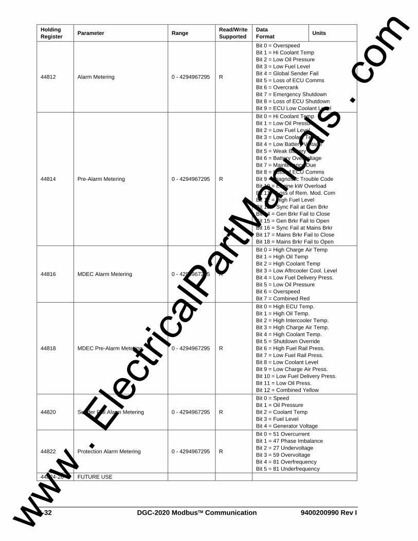
B-32 DGC-2020 Modbus™ Communication 9400200990 Rev I
Holding Register Parameter Range Read/Write
Supported Data Format Units
44812 Alarm Metering 0 - 4294967295 R
Bit 0 = Overspeed Bit 1 = Hi Coolant Temp Bit 2 = Low Oil Pressure Bit 3 = Low Fuel Level Bit 4 = Global Sender Fail Bit 5 = Loss of ECU Comms Bit 6 = Overcrank Bit 7 = Emergency Shutdown Bit 8 = Loss of ECU Shutdown Bit 9 = ECU Low Coolant Level
44814 Pre-Alarm Metering 0 - 4294967295 R
Bit 0 = Hi Coolant Temp Bit 1 = Low Oil Pressure Bit 2 = Low Fuel Level Bit 3 = Low Coolant Temp Bit 4 = Low Battery Voltage Bit 5 = Weak Battery Bit 6 = Battery Overvoltage Bit 7 = Maintenance Due Bit 8 = Loss of ECU Comms Bit 9 = Diagnostic Trouble Code Bit 10 = Engine kW Overload Bit 11 = Loss of Rem. Mod. Com Bit 12 = High Fuel Level Bit 13 = Sync Fail at Gen Brkr Bit 14 = Gen Brkr Fail to Close Bit 15 = Gen Brkr Fail to Open Bit 16 = Sync Fail at Mains Brkr Bit 17 = Mains Brkr Fail to Close Bit 18 = Mains Brkr Fail to Open
44816 MDEC Alarm Metering 0 - 4294967295 R
Bit 0 = High Charge Air Temp Bit 1 = High Oil Temp Bit 2 = High Coolant Temp Bit 3 = Low Aftrcooler Cool. Level Bit 4 = Low Fuel Delivery Press. Bit 5 = Low Oil Pressure Bit 6 = Overspeed Bit 7 = Combined Red
44818 MDEC Pre-Alarm Metering 0 - 4294967295 R
Bit 0 = High ECU Temp. Bit 1 = High Oil Temp. Bit 2 = High Intercooler Temp. Bit 3 = High Charge Air Temp. Bit 4 = High Coolant Temp. Bit 5 = Shutdown Override Bit 6 = High Fuel Rail Press. Bit 7 = Low Fuel Rail Press. Bit 8 = Low Coolant Level Bit 9 = Low Charge Air Press. Bit 10 = Low Fuel Delivery Press. Bit 11 = Low Oil Press. Bit 12 = Combined Yellow
44820 Sender Fail Alarm Metering 0 - 4294967295 R
Bit 0 = Speed Bit 1 = Oil Pressure Bit 2 = Coolant Temp Bit 3 = Fuel Level Bit 4 = Generator Voltage
44822 Protection Alarm Metering 0 - 4294967295 R
Bit 0 = 51 Overcurrent Bit 1 = 47 Phase Imbalance Bit 2 = 27 Undervoltage Bit 3 = 59 Overvoltage Bit 4 = 81 Overfrequency Bit 5 = 81 Underfrequency
44824-26 FUTURE USE
www . El
ectric
alPar
tMan
uals
. com

9400200990 Rev I DGC-2020 Modbus™ Communication B-33
Holding Register Parameter Range Read/Write
Supported Data Format Units
44828 Local Input Metering 0 - 4294967295 R
Bit 0 = Input 1 Bit 1 = Input 2 Bit 2 = Input 3 Bit 3 = Input 4 Bit 4 = Input 5 Bit 5 = Input 6 Bit 6 = Input 7 Bit 7 = Input 8 Bit 8 = Input 9 Bit 9 = Input 10 Bit 10 = Input 11 Bit 11 = Input 12 Bit 12 = Input 13 Bit 13 = Input 14 Bit 14 = Input 15 Bit 15 = Input 16
44830 Local Output Metering 0 - 4294967295 R
Bit 0 = Output 1 Bit 1 = Output 2 Bit 2 = Output 3 Bit 3 = Output 4 Bit 4 = Output 5 Bit 5 = Output 6 Bit 6 = Output 7 Bit 7 = Output 8 Bit 8 = Output 9 Bit 9 = Output 10 Bit 10 = Output 11 Bit 11 = Output 12
44832 Status Metering 0 - 4294967295 R
Bit 0 = EPS Supplying Load Bit 1 = Single Phase Override Bit 2 = Single Phase AC Override Bit 3 = Low Line Override Bit 4 = Auto Transfer Switch Bit 5 = Battle Override Bit 6 = Grounded Delta Override Bit 7 = Mains Breaker Closed Bit 8 = Gen Breaker Closed
44834 Hours Until Maintenance 0-5000 R Hours in increments of 1 44836 Cum. Total Engine Run Hrs. 0 - 99,999 R Hours in increments of 1 44838 Cum. Total Engine Run Min. 0-60 R Minutes in increments of 1 44840 Cum. Loaded Engine Run Hrs. 0 - 99,999 R Hours in increments of 1 44842 Cum. Loaded Engine Run Min. 0-60 R Minutes in increments of 1 44844 Cum. Unloaded Engine Run Hrs. 0 - 99,999 R Hours in increments of 1 44846 Cum. Unloaded Engine Run Min. 0-60 R Minutes in increments of 1 44848 Cum. Total kW-Hrs 0 - 4294967295 R KW-Hrs in increments of 1 44850 FUTURE USE 44852 Commission Date Month 1-12 R Month in increments of 1 44854 Commission Date Day 1-31 R Day in increments of 1 44856 Commission Date Year 0 - 4294967295 R Year in increments of 1 44858 Session Total Engine Run Hrs. 0 - 99,999 R Hours in increments of 1 44860 Session Total Engine Run Min. 0-60 R Minutes in increments of 1 44862 Session Loaded Engine Run Hrs. 0 - 99,999 R Hours in increments of 1 44864 Session Loaded Engine Run Min. 0-60 R Minutes in increments of 1 44866 Session Unloaded Engine Run Hrs. 0 - 99,999 R Hours in increments of 1 44868 Session Unloaded Engine Run Min. 0-60 R Minutes in increments of 1 44870 Session kW-Hrs 0 - 4294967295 R KW-Hours
44872 Cumulative Number of Engine Starts 0 - 4294967295 R Quantity in increments of 1
44874 Session Start Date Month 1-12 R Month in increments of 1 44876 Session Start Date Day 1-31 R Day in increments of 1 44878 Session Start Date Year 0 - 4294967295 R Year in increments of 1
www . El
ectric
alPar
tMan
uals
. com

B-34 DGC-2020 Modbus™ Communication 9400200990 Rev I
Holding Register Parameter Range Read/Write
Supported Data Format Units
44880 Generator Status 0 - 11 R
0 = RESET State 1 = READY State 2 = CRANKING State 3 = RESTING State 4 = RUNNING State 5 = ALARM State 6 = PRESTART State 7 = COOLING State 8 = CONNECTING State 9 = DISCONNECT State 10 = PULSING State 11 = UNLOADING State
44882-918 FUTURE USE 44920-48 RESERVED
44950 Global Alarm 0-1 R 0 = No system alarms in effect 1 = System alarm(s) in effect
44952 Global Pre-Alarm 0-1 R 0 = No system pre-alarms in effect 1 = System pre-alarm(s) in effect
44954 Local Configurable Inputs Pre-Alarm Bits R Bit 0 = Input 1, Bit 1 = Input 2, etc.
44956 Local Configurable Inputs Alarm Bits R Bit 0 = Input 1, Bit 1 = Input 2, etc.
44958 Configurable Elements Status Bits R Bit 0 =Config Element 1, Bit 1 = Config Element 2, etc.
44960 Configurable Elements Pre-Alarm Bits R Bit 0 = Config Element 1, Bit 1 = Config
Element 2, etc.
44962 Configurable Elements Alarm Bits R Bit 0 = Config Element 1, Bit 1 = Config Element 2, etc.
44964 Remote Inputs Status Bits R Bit 0 = Remote Input 17, Bit 2 = Remote Input 18, etc.
44966 Remote Outputs Status Bits R Bit 0 = Remote Output 13, Bit 1 = Remote Output 14, etc.
44970 Remote Configurable Inputs Pre-alarm Bits R Bit 0 = Remote Input 17, Bit 1 = Remote
Input 18, etc.
44972 Remote Configurable Inputs Alarm Bits R Bit 0 = Remote Input 17, Bit 1 = Remote
Input 18, etc. 44974-98 RESERVED R
45000 ECU Lamp Status 0 - 4294967295 R
Bit 24 = Malfunction Bit 27 = Stop Bit 28 = Warning Bit 31 = Protect
45002 Number of DTC’s 0 - 4294967295 R Quantity in increments of 1
www . El
ectric
alPar
tMan
uals
. com

Route 143, Box 269, Highland, Illinois U.S.A. 62249Tel +1 618.654.2341 Fax +1 618.654.2351
e-mail: [email protected]
No. 1300 North Zhongshan Road, Wujiang Economic Development ZoneSuzhou, Jiangsu Province - P.R. China 215200
Tel +86(0)512 6346 1730 Fax +86(0)512 6346 1760e-mail: [email protected]
P.A.E. Les Pins, 67319 Wasselonne Cedex FRANCETel +33 3.88.87.1010 Fax +33 3.88.87.0808
e-mail: [email protected] . El
ectric
alPar
tMan
uals
. com