Digital Gas Detector/Controller - fixed gas monitor | Opera...
24
Inc. 6000 Series Digital Gas Detector/Controller Operation Manual Version 000.02
Transcript of Digital Gas Detector/Controller - fixed gas monitor | Opera...

Inc.6000 Series Digital Gas Detector/Controller
Operation Manual
Version 000.02

6000 Series Digital Gas Detector/Controller
TABLE OF CONTENTSGeneral Description Applications Features Outputs User InterfaceModel Selection GuideInstallation Wiring Installation GuideOperation Screen Display Default Settings Changing Settings List of SettingsNetwork Configuration Using Central Controller Using No Central Controller Defaults Configuration Addresses Creating Zones or Groups Output RelaysMaintenance Guide Quick Test Caution Calibration Procedure
1.0 1.1 1.2 1.3 1.42.03.0 3.1 3.24.0 4.1 4.2 4.3 4.45.0 5.1 5.2 5.3 5.4 5.5 5.66.0 6.1 6.2
Inc.

6000 Series Digital Gas Detector/Controller
The Opera series 6000 gas detectors offer commercial building owner’s the precision to assure the health and safety to occupants with the tightest possible controls on energy consumption. It is a versatile, self-contained dual gas sensor that is network ready for either peer-to-peer (master slave) operation or central control for a smooth integration into new or existing energy management systems.
1.0 GENERAL DESCRIPTION
1.1 Applications:Vehicle EmissionsCombustible GasesRefrigerant Gas Leak DetectionIndustrial Health and Safety
1.2 Features:Stand-alone operation with 1 or 2 adjustable alarm relays, indicators and strobeBTL listed Smart SensorBACnet MS/TP RS485 interfaceCAN network interface for master-slave operation or central controlPre-calibrated plug-and-play sensor modulesImpact resistant water proof enclosure
1.0 General DescriptionInc.

6000 Series Digital Gas Detector/Controller
1.3 OutputsDigital networks CAN network for central control or peer-to-peer BACnet MS/TP RS485 (BTL listed)Relays (2 on model 6000-B, 1 on model 6000-A) On delay; 0-999 seconds (16 minutes) Off delay; 0-999 seconds (16 minutes)
1.4 User Interface:Back lit LCD display shows gas concentration, user settings, calibration controlsRed LED alarm indicators, level 1 and 2High intensity white LED strobe on level 3Audible alarm, 85 db at 1 meter4 pushbutton user keypadPassword control for settings
1.0 General DescriptionInc.

6000 Series Digital Gas Detector/Controller
2.0 MODEL SELECTION GUIDE
AmmoniaArgon (O2 depletion)ButaneCarbon DioxideCarbon DioxideCarbon MonoxideCarbon MonoxideCarbon MonoxideChlorineEthylene glycolEthanolHCFCsHFCsHelium (O2 depletion)Humidity (relative)HydrogenHydrogen sulfideIso-butaneIso-propyl AlcoholMethaneMethanolNitrogen (oxygen depletion)Nitrogen dioxideOrganic VaporsOxygenPropane
NH3Ar
C4H10CO2CO2COCO
CO H2nilCL2
C2H4(OH)2C2H5OH
HeH2O in air
H2H2S
C4H10C3H7OH
CH4CH3OH
NO2VOCs
O2C3H8
04230515-200015-50000202-25002H2nil170101132023250816050105012314012206
0-250 ppm0-50% O20-50% LEL0-2000 ppm0-5000 ppm0-100 ppm0-250 ppm0-100 ppm0-10 ppm0-1000 ppm0-1000 ppm
0-25% O20-100% RH0-50% LEL0-50 ppm0-50% LEL0-1000 ppm0-50% LEL0-1000 ppm0-50% O20-10 ppm0-1000 ppm0-50% O20-50 % LEL
Gas Type Range
Controller 6000
Example:
6 0 0 2 - 1 4 - BB = (BACnet Version)A = (Analog Version)Gas Type
Complete part number Gas TypeIf second sensor installed
2.0 Model Selection GudieInc.

6000 Series Digital Gas Detector/Controller
321 654 987 121110 151413
EOL EOL
Transformer 120/24v
5 va for each unit
Independant circuit 120 vac
Use class 2 type
NL
To other detectors
To magnetic starter coil or control relay coil for local control
CAN network communication shield (on first unit only)
CAN network communication lowCAN network communication high
BACnet MSTP communication shield (no connect)
BACnet MSTP communication -BACnet MSTP communication +
N L
24V or
120V
3.0 INSTALLATION
3.0 Installation
3.1.1 Wiring – Model 6000-BBacnet Version
NO C NC G AC+ AC- S L H S + -
AL1 AL2NO C NC
Inc.

6000 Series Digital Gas Detector/Controller
321 654 987 121110 151413
EOL EOL
Transformer 120/24v
5 va for each unit
N LIndependant circuit
120 vac
Use class 2 type
NL
To other detectors
To magnetic starter coil or control relay coil for local control
CAN network communication shield (on first unit only)
CAN network communication lowCAN network communication high
BACnet MSTP communication shield (no connect)
BACnet MSTP communication -BACnet MSTP communication +
NO C NC AN1 G AN2 AC+ AC- BI S L H S + -
Input for limit switch
24 vacor
120 vac
3.0 Installation
3.1.2 Installation, Wiring – Model 6000-AAnalogue Version
4-20 ma (2-10V) to controller, Sensor A
4-20 ma (2-10V) to controller, Sensor BGround
AL1
4-20 4-20
OUTPUT
Inc.

6000 Series Digital Gas Detector/Controller
1.2.
3.
4.
5.
All wiring must conform to local building codes, regulations and laws.
Use ½ in EMT conduit for all wiring.Install enclosed 120/24 vac transformer, 5 va per sensor or controller, using 18 to 20 AWG two conductor wire. Do not tie the secondary to ground. Connect multiple sensors. Ensure that the polarity of the connections are the same at each sensor or controller.Connect relay contacts (usually relay 1) to ventilation system. Use a magnetic starter so that the sensor contacts energize the starter coil and not the fan motor directly.For multiple sensors, chain a shielded twisted pair cable 20 to 24 AWG from screw 6 and 7 on one sensor, to the next and continue chain to the last sensor. Maintain the same polarity on each unit. Do not use star configura-tion. T connections should be less than 3 meters (10 feet) from the chain. Best to make all chain connections at the sensors to avoid T connections.Move the end-of-line jumper (the first one on the left) to the on position (UP) on the first sensor, or controller, on the chain and the last sensor/controller on the chain. A controller can be located anywhere on the chain. Ensure its EOL jumper is off if it is in the middle. Any address assigned to a sensor/controller can be in any location on the chain.
3.2 Installation Guidelines
3.0 InstallationInc.

6000 Series Digital Gas Detector/Controller
6.
7.
Power on the units. They will display the gas type and reading. To verify if the sensors are communicating correctly, change setting no. 56 from 0 to 1 to turn on the network display. Press ↑ and ← simultaneously to save then press and hold ← for a few seconds. The unit will display each sensor connected. If the unit does not display the other sensors scrolling by, check the follow-ing;
To test communication, press and hold the up button on sensor for 5 seconds to start manual mode (5 minutes). This will close the relay 1 on that unit and all of the other units on the network.
each unit has a unique address, setting 39, with no duplicatesend-of-line jumpers are set on units at ends of cable onlypolarity of the communication cable and the 24 vacwire connections for shorts, etc.
3.2 Installation Guidelines (Continued)
3.0 InstallationInc.

Série 6000 Détecteur de gaz numérique/contrôleur
3.3 Position des sondes
3.0 Installation
1.
2.
Pour contrôle de la qualité de l’air d’émissions de gaz d’échappement et l’accumulation des gaz toxiques le rayon effectif de détection généralement acceptable est de 50 pieds (15 mètres). Environ 7 500 pieds carés (700 mètres carés ).Pour la détection de fruite de gaz combustible, ammoni-ac, gaz réfrigérant, le rayon effectif de détection est de 30 pieds (10 mètres) puisquil s’échappe plus rapidement et cause de plus grande risque.
Couverture
Le position des sondes pour une diffusion optimale est basé sur le temps requis entre la lecture des sondes et l’émission du gaz à sa source. Ceci s’applique sur tous les types de sonde.
Le rayon effectif de détection de toutes sondes ne s’étend pas lorqu’il y a un obstacle impliquant une ciculation d’air naturelle. Ceci inclut les murs, les escaliers, les ascenseurs, les étagères avec densité, avec densité, les coffres à utils, etc...La sonde doit ‘VOIR’ le rayon de couverture, sinon une autre sonde sera néces-saire.
Hauteur de montage
La hauteur de montage pour les sondes est basée sur la densité relative à l’air. It y a trois groupes:
1. Plus léger que l’air et concentré près du plafond : hydrogène, méthane (gaz naturel), ammoniac, hélium. Installez à 1 à 3 pieds du plafond.
Inc.

Série 6000 Détecteur de gaz numérique/contrôleur
2.
3.
Densité similaire à lair et qui se dilue également à tous les niveaux : monoxyde de carbone, dioxyde d’azote, hydrogène sulfuré, oxygène, dioxide de carbone. Installez à 3 pieds (1 mètres) du sol et à la moitié de la hauteur du plafond.Plus lourd que l’air et concentré près du plancher : HCFs, HCFCs, propane, chlore, butane et la plupart des vapeurs organiques. Installez à 1 à 3 pieds du placher.
3.0 Installation
3.3 Position des sondes (suite)
Pour tout les types de sonde évitez les courants d’air, les obsta-cles, les aérosols et les silicones. Placez les sondes au centre du rayon de couverture.
Inc.

6000 Series Digital Gas Detector/Controller
4.0 OPERATION4.1 Screen Display
The LCD shows the type of gas and the current gas concentration, depending on the model of sensor module plugged in. If two sensor modules are installed, the display will alternate between them.
1 indicates alarm 1 on, according to the settings 0, 1, 2 or activated by another sensor on the CAN network via setting 36. This is usually the low gas level alarm.
2 indicates alarm 2 on. Per settings 3, 4, 5 or if activated by another sensor on CAN network per setting 37.
3 indicates alarm 3 on. Per settings 6, 7, 8 or if activated by another sensor on CAN network per setting 38.
4.0 Operation
The bottom left corner will also display the alarm status;
Address(See setting
56)
State of the
alarms
Type of gas
Concentration
Inc.

6000 Series Digital Gas Detector/Controller
4.2 Default Settings
User settings are factory pre-loaded with default values to facili-tate set up and can be changed at any time. Upgrading firmware will not affect user settings.
Alarm thresholds should be set to suit local regulations. Default values for these are general guidelines only.
4.3 Changing Settings
Press → and ← to move through the settings. If the keypad lock is on then enter the password first. The screen will display the setting number 0, 1, 2, etc plus the short description (eg; AL1) and the current setting value.
Press the ↑ or ↓ buttons to increase or decrease the setting.To save, press ↑ and ← buttons at the same time. The word “OK” will appear. If you do not see “OK” and the new value it is because the buttons were not pressed simultaneously. Try again.
M indicates manual override mode active. Useful to start ventilation system without the risk of leaving it on (and freez-ing the space in winter). Press and hold ↑ for 5 seconds to start manual mode. Then click again to increase time from 5 to 60 minutes. This activates alarm 1, 2, or 3 (per setting 69) and sends alarm transmit messages in settings 9-17. The unit will return to automatic operation after the time runs down. To cancel manual mode press ↓ several times to reduce time left to run. It will take a few seconds to stop.
T indicates alarm 1 on due to high ambient temperature, setting 51. Useful for summer ventilation.
4.0 OperationInc.

6000 Series Digital Gas Detector/Controller
4.4 List of Settings
No. Name Range0
123
456
789
10
11
12
13
14
15
16
17
AL1
A1DelA1OffAL2
AL2DelAL2OffAL3
A3DelA3OffA1Tx
A1Tx
A1Tx
A2Tx
A2Tx
A2Tx
A3Tx
A3Tx
A3Tx
Alarm 1 threshold, activates relay 1
Alarm 1 Delay on (seconds)Alarm 1 Delay off (seconds)Alarm 2 threshold, activates relay 2Model 6000-B onlyAlarm 2 Delay on (seconds)Alarm 2 Delay off (seconds)Alarm 3 threshold, sounder and strobascopeAlarm 3 Delay on (seconds)Alarm 3 Delay off (seconds)Alarm 1 transmit message, CAN networkAlarm 1 transmit message, CAN networkAlarm 1 transmit message, CAN networkAlarm 2 transmit message, CAN networkAlarm 2 transmit message, CAN networkAlarm 2 transmit message, CAN networkAlarm 3 transmit message, CAN networkAlarm 3 transmit message, CAN networkAlarm 3 transmit message, CAN network
per sensor scale0-9990-999
per sensor scale0-9990-999
per sensor scale0-9990-9990-255
0-255
0-255
0-255
0-255
0-255
0-255
0-255
0-255
3020
3020
180201
2
3
DefaultDescription
Sensor A (top socket) settings
4.0 OperationInc.

6000 Series Digital Gas Detector/Controller
4.4 List of Settings (Continued)
No. Name Range DefaultDescription
Sensor B (bottom socket) settings
4.0 Operation
18
192021
222324
252627
28
29
30
31
32
33
34
35
AL1-B
A1DelA1OffAL2-B
A2DelA2OffAL3-B
A3DelA3OffA1x
AL1Tx
A1Tx
A2Tx
A2Tx
A2Tx
A3Tx
A3Tx
A3Tx
Alarm 1 threshold, activates relay 1
Alarm 1 Delay on (seconds)Alarm 1 Delay off (seconds)Alarm 2 threshold, activates relay 2Model 6000-B onlyAlarm 2 Delay on (seconds)Alarm 2 Delay off (seconds)Alarm 3 threshold, sounder and strobeAlarm 3 Delay on (seconds)Alarm 3 Delay off (seconds)Alarm 1 transmit message, CAN networkAlarm 1 transmit message, CAN networkAlarm 1 transmit message, CAN networkAlarm 2 transmit message, CAN networkAlarm 2 transmit message, CAN networkAlarm 2 transmit message, CAN networkAlarm 3 transmit message, CAN networkAlarm 3 transmit message, CAN networkAlarm 3 transmit message, CAN network
per sensor scale0-9990-999
per sensor scale0-9990-999
per sensor scale0-9990-9990-255
0-255
0-255
0-255
0-255
0-255
0-255
0-255
0-255
3020
3020
180201
2
3
Inc.

6000 Series Digital Gas Detector/Controller
No. Name Range DefaultDescription36
37
38
39
40
41
4243444546
47
48
49
R1Rx
R2Rx
R3Rx
Adr
AnZA
AnSA
AnZBAnSBTempAudBAC
BMA
BBR
KLB
Receive message to activate relay 1, CAN networkReceive message to activate relay 2, CAN network. Model 6000-B onlyReceive message to activate sounder and strobe CAN networkSensor identification address, CAN networkAdjustment to analogue zero (4ma or 2v) to tweak for wire losses and controller input inaccuracies. Also forces zero output. Sensor Aas option 40 but for span adjustment (20ma or 10v). Forces output highas option 40 but for sensor Bas option 41 but for sensor BTemperature display enable off/onLocal audio alarm enable on alarm 3BACnet MSTP mode select0 = BACnet communication disabled1 = BACnet communication enabled2 = BACnet communication enabled and display all sensors on CAN networkBACnet MAC address. Device ID displayed as 50,000 plus BMABACnet baud rate0 = 96001 = 192002 = 384003 = 76800Keyboard lock. Locked keyboard require password to access options
0-255
0-255
0-255
0-32
0/10/1
0/1/2
127
3
0/1
1
2
3
0
010
0
0
4.4 List of Settings (Continued)
General Settings
4.0 OperationInc.

6000 Series Digital Gas Detector/Controller
No. Name Range DefaultDescription
4.4 List of Settings (Continued)
General Settings (Continued)
4.0 Operation
5051
52
5354
55
56
57
TModATHi
W/U
BMMBDiag
ATLo
Net
Ref-A
Temperature modify/calibrateHigh temperature alarm limit used for summer ventilation (Alarm 1 is activated when temperatureexceeds option) Deg CWarm up delay disables alarms (mins) until sensor is stableized after power outageBACnet maximum MAC addressBACnet diagnostic display while accessing this option. In format XXXXYYZZ. Where YY is MAC address (in HEX) of the sensor that just passed the token to the current one. ZZ is the sensor to which the token was passed to. Example 0305 would display on sensor 04Low temperature alarm limit (alarm 3) Deg CEnable local display of all sensors on home screen CAN networkRefrigerant scale and type of gas for sensor AFor model 5520:R507, R23, R134a, R152a, R492a, R404a, R407a, R408a, R410a, R500, R502, R507For model 5513:R22, R21, R141b, R142b, R401a, R402a, R408a, R409a, R502aPress up arrow to select desired gas then save.
-9/+90-99
0-99
0-127
0-99
0/1
060
1
127
0
Inc.

6000 Series Digital Gas Detector/Controller
58
59
60
61
62
64
65
66
68
69
Ref-B
FltTx
ADTxA
AMinA
AMaxA
ADTxB
AMinB
AMaxB
Baud
Man
Press up arrow to select desired gas then save.Fault alarm transit message, CAN networkAnalogue drive transmit message, sensor A (top) CAN network. Used to communicate a percentage drive signal to other sensors or controller via CAN network. Example 8 sensors on CAN network send messages to controller whose analogue is output to modulate a damper or variable speed drive.Analogue drive. Minimum percent of scale for zero output. Sensor AAnalogue drive. Maximum percent of scale for full scale output. Sensor AAnalogue drive transmit message, CAN network sensor BEnable display of all sensor connect-ed via CAN network on this unit. For example see section 4.1Analogue drive. Maximum percent of scale for full scale output. Sensor BBaud rate for CAN networkCAN network baud rate. Maximum network wire length is 1500 feet at rate 0 and 3000 feet at rate 1.Set Baud rate = 1 when used with model 5000 networkManual mode activates alarms 1, 1+2 or 1+2+3. See screen display section.
0-255
0-255
0-100
0-100
0-255
0-100
0-100
0-1
0
0
0
100
100
0
0
100
0
No. Name Range DefaultDescription
4.4 List of Settings (Continued)
General Settings (Continued)
4.0 OperationInc.

6000 Series Digital Gas Detector/Controller
70 BDI Bacnet device instance replacesdefault 5,000 + BMA (parameter)BACnet device instance replace default 5,000 + BMA (setting)
1-3 1
4.4 List of Settings (Continued)
General Settings (Continued)
4.0 Operation
No. Name Range DefaultDescription
Inc.

6000 Series Digital Gas Detector/Controller
5.0 NETWORK CONFIGURATION5.1 Using a Central Controller
A basic model 6000 controller serves as the central connection point for the ventilation system. Model 60XX gas sensors transmit alarm messages to the central controller.
A controller will display up to 32 sensors on the network (64 for dual units). It also displays their address, gas types, gas concen-tration, and alarm status for each. The two relays on board can be configured for different levels of gas or to operate different ventila-tion systems, zones or groups.
5.0 Network Configuration
60xx 60xx 60xx 60xx
60xx 60xx 60xx 60xx
Controller6000
Zone 1
Zone 2
Inc.

6000 Series Digital Gas Detector/Controller
5.2 Using No central controller (master/slave operation)
One of the 60XX series gas sensors can perform the same func-tion as the controller. It can activate the ventilation for all the sensors, or a group. The use of a dedicated controller is optional, - to add a display in some specific location, such as before enter-ing a mechanical room or interface with several fan starters which are located in one place. The low cost of a basic controller makes it easy to use them to reduce costly field wiring where needed.
60xx 60xx 60xx 60xx
60xx 60xx 60xx 60xx
Zone 1
Zone 2
5.0 Network ConfigurationInc.

6000 Series Digital Gas Detector/Controller
5.3 Default Configuration
Sensors are shipped pre-loaded with a default settings which can be changed in the field to suit the desired sequence with simple keypad input. Using the default settings, when one sensor goes into alarm level 1, 2 or 3 it activates its relays and transmits a mes-sage to all other sensors to activate their relays also. The ventila-tion system can be connected to any of the relays (usually level 1). This is essentially a one zone configuration.
5.4 Addresses
Set each sensor and controller to a different address (setting 39). 1, 2, 3, 4 etc. It is important to have no duplicates on the same network cable. Addresses are independent of groupings.
5.5 Creating Zones or groups
To control multiple zones, set the transmit message on sensors to different messages for different zones. The default transmit mes-sages are 1, 2, 3 for alarm levels 1, 2, 3 for zone 1. Set zone 2 sensors to transmit messages to 4, 5, 6 Set zone 3 sensors to transmit 7, 8, 9 and so on.
5.6 Output Relays
Relay number 1 and 2 will activate if the gas on that sensor goes into alarm level 1, or 2. It will also activate when it sees it’s receive code (setting 36, 37) go by on the network, sent by other sensors.
The 6000 basic controller has no sensors on board so the relays will only activate if it sees it’s receive codes. The 6000 controller could control two zones via its two relays. When no controller is used, the master needs to be a member of the group it is controlling.
5.0 Network ConfigurationInc.

6000 Series Digital Gas Detector/Controller
6.0 MAINTENANCE GUIDEAll sensors are shipped from the factory pre-calibrated. To main-tain accuracy and conformity with standards it is essential that they be calibrated by a qualified technician at least once per year using certified bottled gas mixtures.
6.1 Quick Test Caution
Opera does not approve the use of the so called “bump test”. Here, a gas of a higher concentration than the alarm level is simply injected into the sensor to cause the alarm to trigger. The gas in these bottles is a higher concentration than what is used for proper calibration. This only test the operation of the alarm with no regard for the intended alarm settings, similar to simply press-ing a test button.
Use certified precision mixtures to adjust the sensitivity of the sensor due to normal wear and aging and guarantee that the designed alarm set points are respected. It will also indicate the general condition of a sensor that is due for replacement. So called “automatic calibration” or “self-test” will not provide this level of security.
6.0 Maintenance GuideInc.
6000 Series Digital Gas Detector/Controller
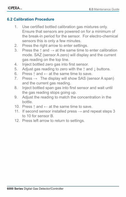
6.2 Calibration Procedure
1.
2.3.
4.5.6.7.
8.
9.
10.11.
12.
Use certified bottled calibration gas mixtures only. Ensure that sensors are powered on for a minimum of the break-in period for the sensor. For electro-chemical sensors this is only a few minutes.Press the right arrow to enter settings.Press the ↑ and → at the same time to enter calibration mode. SAZ (sensor A zero) will display and the current gas reading on the top line.Inject bottled zero gas into first sensor.Adjust gas reading to zero with the ↑ and ↓ buttons.Press ↑ and ← at the same time to save.Press → The display will show SAS (sensor A span) and the current gas reading.Inject bottled span gas into first sensor and wait until the gas reading stops going up.Adjust the reading to match the concentration in the bottle.Press ↑ and ← at the same time to save.If second sensor installed press → and repeat steps 3 to 10 for sensor B.Press left arrow to return to settings.
6.0 Maintenance GuideInc.