Digital Frequency converter for the rotational speed ... · PARAMETER LIST ... inadmissible...
50
Digital Frequency converter for the rotational speed control of 3-phase asynchronous motors 0.25 kw to 0.75 kw unit description 221077E, 01/00 This operating instruction apply for: - KFU .. / 230 - A - DF3 GEORGII KOBOLD AUGUST HEINE GmbH & Co Fasanenweg 6-8 D-70771 Leinfelden-Echterdingen Federal Republic of Germany Telephone: + 49 711/ 7 59 03-0 Telefax: + 49 711/ 7 59 03-53 e-mail: [email protected]
Transcript of Digital Frequency converter for the rotational speed ... · PARAMETER LIST ... inadmissible...

DigitalFrequency converter
for the rotational speed controlof 3-phase asynchronous motors
0.25 kw to 0.75 kw
unit description 221077E, 01/00
This operating instruction apply for:
- KFU .. / 230 - A - DF3
GEORGII KOBOLDAUGUST HEINE GmbH & CoFasanenweg 6-8
D-70771 Leinfelden-Echterdingen
Federal Republic of Germany
Telephone: + 49 711/ 7 59 03-0Telefax: + 49 711/ 7 59 03-53e-mail: [email protected]

unit description 221077E, 01/00
Seite 2 GEORGII KOBOLDAUGUST HEINE GmbH & Co
Copyright by
GEORGII KOBOLD AUGUST HEINE GmbH & Co
All Rights, also those of translation, reserved. Without previous expresswritten approval of the GEORGII KOBOLD AUGUST HEINE GmbH & Cono part of this unit description may be duplicated, reproduced, stored orprocessed in any information system or furher transmitted in another form.
This unit description has been produced carefully. However GEORGIIKOBOLD AUGUST HEINE GmbH & Co undertakes no liability fpr possibleerrors in these operating instructions and their consequences. neither isany liability undertaken for direct damage or consequential damage resultinfrom misuse of the unit.
The relevant regulations regarding safely engineering and radiointerference suppression must be observed in the use of the unit.
Rights reserved to make changes.

unit description 221077E, 01/00
GEORGII KOBOLD Seite 3AUGUST HEINE GmbH & Co
Table of contents
1. GENERAL ............................................................................................................. 5
1.1. TECHNICAL FEATURES ...................................................................................... 51.2. SPECIAL FEATURES ........................................................................................... 51.3. DELIVERY AND PACKAGING .............................................................................. 61.4. COMMISSIONING NOTES .................................................................................... 61.5. MAINTENANCE ................................................................................................. 6
2. CONNECTION AND OPERATING CONDITIONS............................................ 7
2.1. VDE REGULATIONS .......................................................................................... 72.2. MOTOR CABLES ................................................................................................ 72.3. ANALOG AND DIGITAL CONTROL LINE................................................................ 7
3. PARAMETERIZING USING THE OPERATING INTERFACE........................ 9
3.1. CONNECTION AND OPERATION OF THE PLAIN TEXT DISPLAY................................ 93.2. OPERATING VALUES.......................................................................................... 93.3. ERROR MESSAGES ........................................................................................... 10
4. THE MENU STRUCTURE ................................................................................. 11
5. PARAMETER LIST ............................................................................................ 12
6. PARAMETERIZING USING THE PC............................................................... 17
6.1. THE SERIAL INTERFACE ................................................................................... 17
7. OUTPUTS OF THE SEVEN-SEGMENT DISPLAY.......................................... 19
7.1. OUTPUT AT THE STOP ...................................................................................... 197.2. OUTPUT AT CW OR CCW START ........................................................................ 197.3. OUTPUT IN CASE OF A FAULT, A RESET AND COMMUNICATIONS WITH THE PC.... 19
8. FOUR PROGRAMMABLE PARAMETER SETS............................................. 21
8.1. RUNNING-UP TIME .......................................................................................... 218.2. RUNNING-DOWN TIME..................................................................................... 218.3. MAXIMUM ROTATING FIELD FREQUENCY ......................................................... 228.4. FIXED ROTATING FIELD FREQUENCY ................................................................ 228.5. MINIMUM ROTATING FIELD FREQUENCY .......................................................... 228.6. CURRENT LIMITING......................................................................................... 228.7. CORNER FREQUENCY ...................................................................................... 228.8. STATIC BOOST ................................................................................................ 248.9. DYNAMIC BOOST ............................................................................................ 258.10. TEMPORALLY LIMITED BOOST ......................................................................... 258.11. DC BRAKE...................................................................................................... 258.12. DURATION OF THE DC BRAKING...................................................................... 258.13. SLIP COMPENSATION....................................................................................... 258.14. MULTI-FUNCTION OUTPUT (FREQUENCY) ......................................................... 258.15. MULTI-FUNCTION OUTPUT (CURRENT) ............................................................. 268.16. RUNNING-DOWN RAMP 1 = ON, 0 = OFF ........................................................ 26
9. PARAMETER SET-INDEPENDENT PRESETTINGS ..................................... 27
9.1. CLOCK FREQUENCY ........................................................................................ 279.2. LANGUAGE..................................................................................................... 279.3. BRAKING CHOPPER (OPTIONAL)....................................................................... 27

unit description 221077E, 01/00
Seite 4 GEORGII KOBOLDAUGUST HEINE GmbH & Co
9.4. DISPLAY/HIDE THE MENU FOR THE PROGRAMMABLE INPUT TERMINALS ............ 279.5. SHOW PARAMETER SETS ................................................................................. 279.6. I²T CURRENT / I²T TIME ................................................................................... 279.7. TEMPERATURE MONITORING ........................................................................... 289.8. TEMPERATURE SWITCHING-OFF....................................................................... 289.9. FACTORY SETTINGS ........................................................................................ 289.10. COPY PROCESS ............................................................................................... 289.11. FILE NAME ..................................................................................................... 299.12. WRITE PROTECTION........................................................................................ 29
10. SET VALUE ASSIGNMENT.......................................................................... 31
10.1. SET VALUE ..................................................................................................... 3110.2. SET VALUE - HYSTERESIS ............................................................................... 3110.3. SET VALUE - OFFSET ...................................................................................... 3110.4. V/F CHARACTERISTICS .................................................................................... 3210.5. FADE OUT FREQUENCY1, FADE OUT FREQUENCY2............................................ 32
11. PROGRAMMING OF THE DIGITAL INPUTS/OUTPUTS......................... 35
11.1. PARAMETERIZATION OF THE CONTROL INPUTS ................................................. 3511.2. PARAMETERIZATION OF THE CONTROL OUTPUTS .............................................. 3611.3. EXPLANATIONS TO THE CONTROL INPUTS AND OUTPUTS................................... 37
12. CONNECTION DIAGRAM............................................................................ 39
13. DIMENSIONS ................................................................................................. 41
14. TECHNICAL DATA....................................................................................... 43
15. APPLICATION NOTES ................................................................................. 45
15.1. DYNAMIC BRAKING USING A BRAKING CHOPPER .............................................. 4515.2. MOTOR PROTECTION ...................................................................................... 4615.3. CABINET MOUNTING ....................................................................................... 4715.4. MEASURES FOR SECURING THE EMC............................................................... 4715.5. WARNINGS..................................................................................................... 48

unit description 221077E, 01/00
GEORGII KOBOLD Seite 5AUGUST HEINE GmbH & Co
1. General
1.1. Technical featuresThe rotation speed of three-phase induction motors can smoothly beadjusted using the KFU .. / 230 digitalized frequency converters. Theconverter works according to the principle of sine-weighted pulse widthmodulation. Pulse width modulation is controlled by a dual processorsystem. Communication is performed via a conventional plug-in terminalblock. Control connections 1-19 of the frequency converter are floating.
At all devices, a protection of the power module in case of undervoltage,inadmissible converter temperature or short-circuit on the converter outputis guaranteed.
1.2. Special featuresThe practical design offers the following advantages:
L four different installation positions optimize the installation andminimize the space requirement in the switching cabinet
L no additional expenses for direct mounting on machines due to pre-wired power line and motor cables as well as built-in potentiometerand power switch according to customer requirements.
L built-in braking chopper (optional)
Plug-in type operator interface for different installation positionsoffers the following advantages:
L 3-line LC-display
L plain text display
L memory for four files
L 5 operator languages
L on-line parameterization
Easy parameterization via comfortable PC user interface:
L RS-232 interface as standard
L 4 programmable parameter sets each with 3 freely selectable setvalues for positioning tasks or multi-axis drives.
L programmable input/output terminals
High operational safety due to:
L aluminum cases and standard input/output filters provide high noiseimmunity and only slight noise emissions
L short-circuit protection
L the new CCDS-SYSTEM (current-control dynamic scan) prevents theconverter from switching-off at excess current flow

unit description 221077E, 01/00
Seite 6 GEORGII KOBOLDAUGUST HEINE GmbH & Co
L potential isolated set value input
1.3. Delivery and packagingThe converters are delivered packed in carton boxes.
L Please check for transportation damages.
Please notify immediately the shipping company and let them confirm thedamage if you find any outside traces of damages.
Then, inform the supplier of the damage.
1.4. Commissioning notesThe setup location should be selected to allow for sufficient clean and dryairflow for cooling the enclosure. The devices are designed for indoor use.A larger concentration of dust, chemical active substances, fungoid growth,or the penetration of pest can cause a failure of the device.
For thermal reasons, the device has to be mounted vertically.
Special attention has to be paid to sufficiently cool the device whenmounting it in a control cabinet.
1.5. MaintenanceFundamentally, the converters are maintenance-free.
Depending on dust in atmosphere, the air filters of cabinet devices must beregularly controlled and be cleaned if required. With increased pollution,check the isolating gaps and heat sinks more frequently and clean whereappropriate.
Cleaning of the devices is only permissible with halogen-free agents!

unit description 221077E, 01/00
GEORGII KOBOLD Seite 7AUGUST HEINE GmbH & Co
2. Connection and operating conditionsThe perfect function of a frequency converter is only then guaranteed if themains voltage is applied and it does not exceed or fall short of the definedtolerance zones. The tolerance zones of the frequency convertercorrespond to the guidelines defined in VDE 0160.
All conducting connections still carry voltage after shutdown of the supplyvoltage until the intermediate circuit condenser has been unloaded (approx.90 sec). Only in terms of this time, the converter can be considered to bevoltage-free.
Cabling work on the terminal block may only be carried out with a voltage-free converter.
After taking out of service, the devices are to be disposed as requested byapplicable laws or regulations.
2.1. VDE regulationsL The VDE regulations for installing and operating electric equipment are
absolute to be considered.
2.2. Motor cablesWith this converter principle, the motor insulation is burdened in addition bythe switching edges in the voltage. Long motor cables can cause voltageincreases which are not admissible in some applications.
Therefore, the maximum admissible motor cable length totals approx. 100m. Using an external "output choke" option, the length can be furtherincreased. The actual maximum motor cable length depends essentially onthe wiring of the cables (e.g.: underground, cable routing, etc.). Toguarantee an EMC (electromagnetic compatibility) conforming operation,shielded cables (e.g.: LIYCY; cable cross section 1,5 mm²) must be used.The screen is to be connected to the therefore anticipated boltusing anarea as large as possible.
In no case, a connector must be wired between motor and converter.
2.3. Analog and digital control lineShielded cables are to be used for all analog and digital control lines.Control lines and power lines must be routed separately.


unit description 221077E, 01/00
GEORGII KOBOLD Seite 9AUGUST HEINE GmbH & Co
3. Parameterizing using the operating interface
3.1. Connection and operation of the plain text displayThe operator interface with a 3-line backlit display is one possibility ofsetting the parameters of the KFU. The connection of the operator interfaceto the converter is shown in Figure 1
The parameterization is performed quickly and simply on the basis of theclear menu structure (refer to Figure 1) and the parameters displayed inplain text. The PRG key must be pressed to change a selected parameterThe cursor starts to flash. The value can be chaged using the UP, DOWN,PRG, or SH keys. Finally, the changes must be svaed by simultaneouslypressing the PRG and SH keys.
Figure 1: Connector arrangement
Only connect the user interface with the voltage switched-off!
3.2. Operating valuesThe "Operating values" menu item enables an operation status request withregard to the following visible messages:
preset value / Hz current preset value of the rotary fieldfrequency
actual value / Hz actual value of the rotary field frequency
TC active current / Amp current temporary circuit- active current
parameters current active parameter set
conv. temp. / °C current converter temperature
version no. version number of the device software

unit description 221077E, 01/00
Seite 10 GEORGII KOBOLDAUGUST HEINE GmbH & Co
3.3. Error messagesL Voltage too high
Admissible intermediate circuit voltage exceeded.Possible cause:1. Running-down to fast.
L Vltg. too lowDropped below the admissible intermediate circuit voltage.Possible cause:1. Mains voltage to low.
L Conv. temp. to high (stage 1: only as user information)Critical operating temperature of the converter.Possible cause:1. Environment temperature too high.2. Air circulation to low.
L Conv. temp. inadm. (stage 2: converter switches off)Operating temperature of the converter is inadmissible (results inswitching off of the converter)Possible cause:1. Environment temperature too high.2. Air circulation to low.
L Short circuitShort circuit or inadmissible high output currentPossible causes:1. Set corner frequency to low2. Static and (or) dynamic BOOST set to high3. DC brake set to high4. Running-up time to short5. Running-down time to short6. External short circuit on the outputs
L Motor temperature to high1. corner frequency set too low.2. static boost set too high during longer lasting operation of the
motor with low rotary field frequencies3. Clock operation with short running-up times
L I²t errorProgrammed current integral error exceeded overdue

unit description 221077E, 01/00
GEORGII KOBOLD Seite 11AUGUST HEINE GmbH & Co
4. The menu structure
Figure 2: The menu strucutre

unit description 221077E, 01/00
Seite 12 GEORGII KOBOLDAUGUST HEINE GmbH & Co
5. Parameter listThe values of all parameters stored in the KFU are shown in tables Table 1and Table 2. These values become active after enabling the factory setting(cf., section 9.9). Tables Table 3 and Table 4 offer the possibility of enteringindividual parameters. Parameter set 2 is active if no further wiring iscarried out (refer to 9. and 11.).
Parameter set-depending variables
Parameter set 1 2 3 4
Run.-up time 2.0 sec. 6.0 sec. 6.0 sec. 6.0 sec.
Run.-down time 2.0 sec. 6.0 sec. 6.0 sec. 6.0 sec.
Max. frequency 120 Hz 120 Hz 120 Hz 120 Hz
Fix frequency 40 Hz 40 Hz 40 Hz 40 Hz
Min. frequency 0 Hz 0 Hz 0 Hz 0 Hz
Max. current 3.0 A 3.0 A 3.0 A 3.0 A
Corner freq. 50 Hz 50 Hz 50 Hz 50 Hz
stat. boost 4 % 4 % 8 % 8 %
dyn. boost 0 % 0 % 0 % 0 %
Time boost 0.0 s 0.0 s 0.0 s 0.0 s
Brake voltage 0 % 0 % 0 % 0 %
Brake time 0.0 s 0.0 s 0.0 s 0.0 s
Slip compens. 0.0 % 0.0 % 0.0 % 0.0 %
Multi freq. 100 Hz 100 Hz 100 Hz 100 Hz
Multi current 0.0 A 0.0 A 0.0 A 0.0 A
Ramp 1 (ON) 1 (ON) 1 (ON) 1 (ON)
Table 1: Factory-set parameters

unit description 221077E, 01/00
GEORGII KOBOLD Seite 13AUGUST HEINE GmbH & Co
Parameter set-independent variable
General Progr. terminals
Clock freq . 2 kHz Inputs
Language English Start cw cl. 8
RS 232 9600 baud Start ccw cl. 7
Brake chopper deactive Par selec. 0 cl. 6
Progr. cl. fade out Par selec. 1 deactivated
Display P. P.-set 1-2 Fix frequency deactivated
I*I*t (current) ∞ Min. frequen. cl. 5
I*I*t (time) ∞ Input reset deactivated
Over temp. 60ºC Terminal ass.
Deact. temp. 65ºC Reaction time 0000ms
Pass word FDxxxxxx
Preset value Outputs
Preset value Potentiom. (10k) General fault VCC --> 15
Thres. preset activate Multi-function VCC --> 16
Offset preset 0 LSB
V/f character. linear
Fade-out freq1 deactiveated
Fade-out freq2 deactiveated
Table 2: Factory-set parameters

unit description 221077E, 01/00
Seite 14 GEORGII KOBOLDAUGUST HEINE GmbH & Co
Where have the paramerters been saved and under whitch file name ?
Datamemory
KFU Operat. instr1st file
Operat. instr2nd file
Operat. instr3rd file
Operat. instr4th file
File name
Parameter set-depending variables
Parameter set 1 2 3 4
Run.-up time sec. sec. sec. sec.
Run.-down time sec. sec. sec. sec.
Max. frequency Hz Hz Hz Hz
Fix frequency Hz Hz Hz Hz
Min. frequency Hz Hz Hz Hz
Max. current A A A A
Corner freq. Hz Hz Hz Hz
stat. boost % % % %
dyn. boost % % % %
Time boost s s s s
Brake voltage % % % %
Brake time s s s s
Slip compens. % % % %
Multi freq. Hz Hz Hz Hz
Multi current A A A A
Ramp
Table 3: Individually set parameters

unit description 221077E, 01/00
GEORGII KOBOLD Seite 15AUGUST HEINE GmbH & Co
Parameter set-independent variable
General Progr. terminals
Clock freq Inputs
Language Start cw
RS 232 Start
Brake chopper Par selec. 0
Progr. Par selec. 1
Display P. Fix frequency
I*I*t (current) Min. frequen.
I*I*t (time) Input reset
Over temp. Terminal ass.
Deact. temp. Reaction time
Pass word
Preset value Outputs
Preset value General fault
Thres. preset Multi-function
Offset preset
V/f character.
Fade-out freq1
Fade-out freq2
Table 4: Individually set parameters


unit description 221077E, 01/00
GEORGII KOBOLD Seite 17AUGUST HEINE GmbH & Co
6. Parameterizing using the PC
6.1. The serial interfaceTheserial RS-232C interface of the KFU .. / 230 is used for communicationwith a supervisory station. In this so-called master/slave operation, the KFUis operated as a slave that is controlled or parameterized by means of aPC, a programmable controller, a microcontroller or other facilities with anUART interface.
Figure shows the connections of the serial interface. Potential separationprovides for an undisturbed data transfer.
Figure 3: RS232 pin assignment


unit description 221077E, 01/00
GEORGII KOBOLD Seite 19AUGUST HEINE GmbH & Co
7. Outputs of the seven-segment displayDepending on operating mode of the converter (stop, cw start , ccw start,fault), important information are output for the operator via the seven-segment display.
7.1. Output at the stopIf a stop is preset for the converter then the preset value is displayed on theseven-segment display.
Example: if the set preset value is 11 Hz, then -, 0, 1,1 is shown in thissequence. These values are constantly displayed until other preset valuesare set or the converter is switched into another operating mode.
7.2. Output at cw or ccw startIf a cw or ccw start is preset for the converter then a line circling in thedetermined direction is shown on the display.
7.3. Output in case of a fault, a reset and communicationswith the PC
The current status of the converter is output via the seven-segment display.
1st digit short circuit (see 3.3)
2n digit undervoltage (see 3.3)
3rd digit overvoltage (see 3.3)
4th digit converter temperature too high (see 3.3)
4th digit (flashing) converter temperature inadmissibly (refer to 3.3)
5th digit motor temperature too high (refer to 3.3)
6th digit not used
7th digit I 2 x t (the integral of the current across the time was exceededrefer to 3.3)
8th digit not used
9th digit not used
letter C communications with the PC (refer to 6.1.)
letter F reset active (refer to 11)

unit description 221077E, 01/00
GEORGII KOBOLD Seite 21AUGUST HEINE GmbH & Co
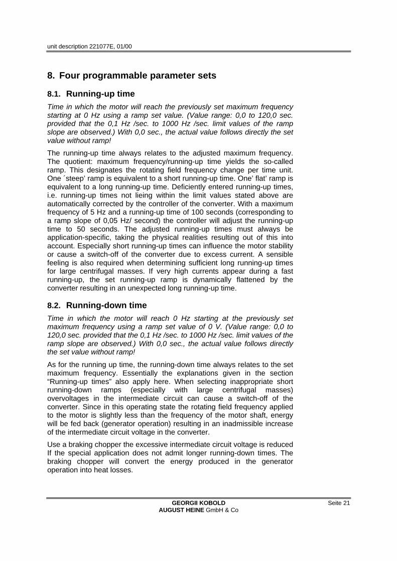
8. Four programmable parameter sets
8.1. Running-up timeTime in which the motor will reach the previously set maximum frequencystarting at 0 Hz using a ramp set value. (Value range: 0,0 to 120,0 sec.provided that the 0,1 Hz /sec. to 1000 Hz /sec. limit values of the rampslope are observed.) With 0,0 sec., the actual value follows directly the setvalue without ramp!
The running-up time always relates to the adjusted maximum frequency.The quotient: maximum frequency/running-up time yields the so-calledramp. This designates the rotating field frequency change per time unit.One ´steep’ ramp is equivalent to a short running-up time. One’ flat’ ramp isequivalent to a long running-up time. Deficiently entered running-up times,i.e. running-up times not lieing within the limit values stated above areautomatically corrected by the controller of the converter. With a maximumfrequency of 5 Hz and a running-up time of 100 seconds (corresponding toa ramp slope of 0,05 Hz/ second) the controller will adjust the running-uptime to 50 seconds. The adjusted running-up times must always beapplication-specific, taking the physical realities resulting out of this intoaccount. Especially short running-up times can influence the motor stabilityor cause a switch-off of the converter due to excess current. A sensiblefeeling is also required when determining sufficient long running-up timesfor large centrifugal masses. If very high currents appear during a fastrunning-up, the set running-up ramp is dynamically flattened by theconverter resulting in an unexpected long running-up time.
8.2. Running-down timeTime in which the motor will reach 0 Hz starting at the previously setmaximum frequency using a ramp set value of 0 V. (Value range: 0,0 to120,0 sec. provided that the 0,1 Hz /sec. to 1000 Hz /sec. limit values of theramp slope are observed.) With 0,0 sec., the actual value follows directlythe set value without ramp!
As for the running up time, the running-down time always relates to the setmaximum frequency. Essentially the explanations given in the section“Running-up times” also apply here. When selecting inappropriate shortrunning-down ramps (especially with large centrifugal masses)overvoltages in the intermediate circuit can cause a switch-off of theconverter. Since in this operating state the rotating field frequency appliedto the motor is slightly less than the frequency of the motor shaft, energywill be fed back (generator operation) resulting in an inadmissible increaseof the intermediate circuit voltage in the converter.
Use a braking chopper the excessive intermediate circuit voltage is reducedIf the special application does not admit longer running-down times. Thebraking chopper will convert the energy produced in the generatoroperation into heat losses.

unit description 221077E, 01/00
Seite 22 GEORGII KOBOLDAUGUST HEINE GmbH & Co
8.3. Maximum rotating field frequencyThe maximum rotating field frequency to be set in advance that theconverter should never exceed even if the utmost set value (valid range: 0V to 10 V) is applied to the analog input.
(Value range: fixed rotating field frequency - 250 Hz)
8.4. Fixed rotating field frequencyFixed frequency, the converter assumes regardless of the default analogset value.
(Value ranges:minimum rotating field frequency - maximum rotatingfield frequency)
Note: For activating this function, an input must be re-programmed sinceonly a limited number of inputs are available (refer to section 11.1).
8.5. Minimum rotating field frequencyThe minimum rotating field frequency to be set in advance that theconverter should not drop below even if the lowest set value is applied tothe analog input.
(Value range: 0 - fixed rotating field frequency)
This means that the specified value may not exceed the fixed rotating filedfrequency value defined in section 8.5.
Note: Only for pre-setting: a min. frequency of 1 Hz will result in afrequency of 0 Hz with an applied set value of 0 volt. With a setfrequency exceeding 1 Hz, a frequency of 0 Hz can only beobtained via a STOP or a RESET. The turning direction definedwith the minimum frequency depends on the polarity of the appliedset value voltage.
8.6. Current limitingCurrent to be set in advance that the converter tries to limit itself to byholding the rotating field frequency or by lowering this frequency.
(Value range: 0.4 -10.0 amps)
8.7. Corner frequencyRotating field frequency, the motor is operated with when the converter issupplying the maximum voltage. (Value range: 30 -250 Hz)
With an increased/decreased the stator frequency, the number of rotorrotations is also increased/ decreased. With an increasing number of rotorrotations, the induction voltage also increases. To preserve a constanttorque at different number of rotations, the magnetic flow must however bekept steady. This results in the consequence that the proportionality mustbe guaranteed between rotating field frequency and voltage, e. g. theoutput voltage increases linearly with the rotating field frequency. This

unit description 221077E, 01/00
GEORGII KOBOLD Seite 23AUGUST HEINE GmbH & Co
relation is guaranteed up to the corner frequency. Above the cornerfrequency, the converter cannot increase the voltage anymore. But with anincreased frequency, the magnetic flow cannot be held steady any longer.The motor is now operated in the so-called field weakening range. With anincreased frequency the motor torque is now reduced converselyproportionally to the rotating field frequency. As a consequence the motorshould usually be operated only up to the corner frequency. At a highnumber of rotations the frictional losses are unproportionally high increased(e. g.: by the fan). If the torque to be achieved becomes too large, themotor ‘tips’ , i.e. the torque submitted by the motor suddenly falls and thenumber of shaft rotations quickly drops to low values. A restart is onlypossible by drastically reducing the rotating field frequency or by a newstart.
With the corner frequency set to low for the respective motor a destructionof the motor can be caused by thermal overload. The converter might alsobe switched off by excess current.
Figure 4: Standadized output voltage as function of the cornerfrequency (linear V/f characteristics)
Figure 5: Standadized output voltage as function of the cornerfrequency (square V/f characteristics)

unit description 221077E, 01/00
Seite 24 GEORGII KOBOLDAUGUST HEINE GmbH & Co
8.8. Static boostDeviating from the linear V/f characteristics, this voltage increase isspecified in percent of the nominal voltage for increasing the starting torqueat low rotating field frequencies.
(Value ranges: 0 - 30%)
With low rotations, the copper resistance of the stator winding stronglyinfluences the operating characteristics of the motor. Without voltagecorrection, the breakdown torque is significantly reduced towards lowrotating field frequencies. During slow starts it could happen that the motordoes not start due a too high breakaway torque to be obtained. By using avoltage increase - the so-called BOOST - the starting torque is increased.The amount of the BOOST is specified in percentage of the nominalvoltage at 0 Hz. With an increasing frequency, the voltage is continuallyraised starting at this value and approaches thereby the normal (linear) V/fcharacteristics: V/f = const. A constantly available voltage increase is called´static BOOST´. The range of the voltage increase extends to about up to afrequency of 2/3 of the corner frequency. To prevent a torque step duringtransition of the BOOST to the V/f=constant characteristics, allcharacteristics of the static BOOST end at the V/f characteristics.
Good starting torques are achieved with a BOOST setting of 8%.Exaggerated high values result in an increased motor temperature whichcan result in the destruction of the motor by overheating, particularly if noforced cooling is used. A high BOOST value can cause an excessivecurrent resulting also in the switch-off the converter.
Figure 6: Standardized output voltage as a function of thefrequency and boost

unit description 221077E, 01/00
GEORGII KOBOLD Seite 25AUGUST HEINE GmbH & Co
8.9. Dynamic boostDeviating from the linear V/f characteristics, this “timely limited” voltageincrease is specified in percent of the nominal voltage for increasing thestarting torque at low rotating field frequencies.
(Value ranges: 0 - 30%)
By using the dynamic BOOST the motor is exposed to a thermal limitedminimal burden. The dynamic BOOST is added to a possibly present staticBOOST. The same explanations apply as for the static BOOST.
8.10. Temporally limited boostDuring the running-up the dynamic boost is activated for the set durationwhen exceeding 1Hz.
(Value range: 0.1 - 25.0 sec)
8.11. DC brakeValue specified in percentage of the nominal voltage which determines thestopping torque (torque at standstill) of the motor (“DC brake”).
(Value range: 0 - 20%)
Note: Despite a high torque generated by the motor at a rotating fieldfrequency of 0 Hz, the motor shaft can slowly be rotated by anexternally applied torque since this is not a regulated system.
8.12. Duration of the DC brakingTemporal duration of the effectiveness of the DC brake.
(Value range: 0.1 - 25.0 sec.)
To prevent a thermal overload of the motor, the DC brake is limited to amaximum of 25 seconds and it is activated when reaching 0 Hz. DCbraking can either be activated by applying a set value of 0 V or by a STOPcommand. DC braking remains active for the entire preset time if the setvalue is not increased again during braking or a START command isissued. During reversing, DC braking is not activated.
8.13. Slip compensationCompensation of the difference of the rotating field frequency and rotorfrequency.
(Value range: 0.1 - 25%)
8.14. Multi-function output (frequency)For setting the rotating field frequency at which the multi-function relayshould be activated. This relay function is activated by specifying a defaultvalue greater than ZERO.
(Value range: 2 - 250 Hz)

unit description 221077E, 01/00
Seite 26 GEORGII KOBOLDAUGUST HEINE GmbH & Co
8.15. Multi-function output (current)For setting the amount of current at which the multi-function relay should beactivated. To activate this function, the value entered for the “Multi-functionoutput/frequency” parameter must be ZERO.
(Value range: 0.1 - 20.0 amps)
8.16. Running-down ramp 1 = ON, 0 = OFFWith no signal applied to the Start/Stop input and 1 (ONE) was specified forthis parameter, the converter reduces the rotating field frequencycorresponding the set running-down ramp. Otherwise, the converterreleases the motor shaft immediately.
unit description 221077E, 01/00
GEORGII KOBOLD Seite 27AUGUST HEINE GmbH & Co
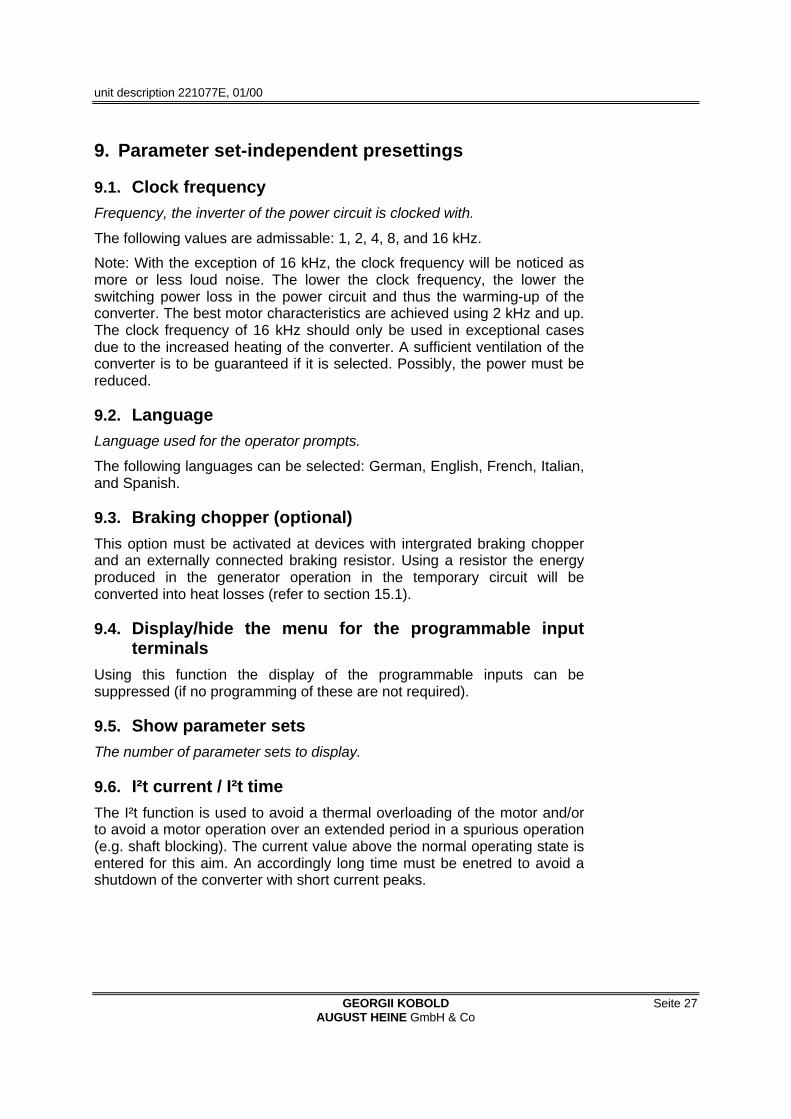
9. Parameter set-independent presettings
9.1. Clock frequencyFrequency, the inverter of the power circuit is clocked with.
The following values are admissable: 1, 2, 4, 8, and 16 kHz.
Note: With the exception of 16 kHz, the clock frequency will be noticed asmore or less loud noise. The lower the clock frequency, the lower theswitching power loss in the power circuit and thus the warming-up of theconverter. The best motor characteristics are achieved using 2 kHz and up.The clock frequency of 16 kHz should only be used in exceptional casesdue to the increased heating of the converter. A sufficient ventilation of theconverter is to be guaranteed if it is selected. Possibly, the power must bereduced.
9.2. LanguageLanguage used for the operator prompts.
The following languages can be selected: German, English, French, Italian,and Spanish.
9.3. Braking chopper (optional)This option must be activated at devices with intergrated braking chopperand an externally connected braking resistor. Using a resistor the energyproduced in the generator operation in the temporary circuit will beconverted into heat losses (refer to section 15.1).
9.4. Display/hide the menu for the programmable inputterminals
Using this function the display of the programmable inputs can besuppressed (if no programming of these are not required).
9.5. Show parameter setsThe number of parameter sets to display.
9.6. I²t current / I²t timeThe I²t function is used to avoid a thermal overloading of the motor and/orto avoid a motor operation over an extended period in a spurious operation(e.g. shaft blocking). The current value above the normal operating state isentered for this aim. An accordingly long time must be enetred to avoid ashutdown of the converter with short current peaks.

unit description 221077E, 01/00
Seite 28 GEORGII KOBOLDAUGUST HEINE GmbH & Co
9.7. Temperature monitoringThe integrated temperature monitoring enables the output of a warningsignal while exceeding the set temperature. The warning is shown on theoperating interface in the form of a flashing "converter temperature toohigh" message.
Furthermore, there is the possibility to output the warning signal to theprogrammable digital outputs (refer to 11.2)
9.8. Temperature switching-offWhile exceeding the set temperature, the switching-off of the frequencyconverter is performed paralled by outputting the "converter temperatureinadmissible" message and the signalling of the digit 4 on the seven-segment display.
9.9. Factory settings
The factory settings is activated by selecting " → copy? Y "and causes theoverwriting of every parameter with the preset factory values (cf., section5).
9.10. Copy processThe operating interface contains a memory that enables the storing of fourfiles. A file contains all parameters available in the frequency converter(refer to figure Figure 7). Furthermore, the possibility exists to assign a filean individual file name consisting of eight freely selectable charcters. Thisfile name is read on-line without initiating a copy operation. Eight questionmarks shown instead of a file name signal a missing memory (memoryarea).
The following examples should clarify the structure and the programexecution of the possible copy operations.
1. Band1 --> FD copies the 1st file of the operating interface with the Band1file name into the
Figure 7: 1st example of a copy process

unit description 221077E, 01/00
GEORGII KOBOLD Seite 29AUGUST HEINE GmbH & Co
FD -> 3. Milling machine copies all parameters of the FD to the 3rd fileof the operating interfaces with the Miller filename (precondition: write protection isinactive)
Figure 8: 2nd example of a copy process
9.11. File nameA file name with eight freely selectable characters can be entered for thedesignation of the parameters stored in the FD. While copying allparameters of the FD into the memory of the operating interface, the filename offers a designation possibility of the four files (refer to 9.11).
9.12. Write protectionThe write protection refers exclusively to the four files of the operatinginterface. It is used as a safety measure concerning operating errors withregard to unintentional overwriting of files. With active write protection, a filecan only be read by the frequency converter. The attempt to overwrite aprotected file is prompted by an error message.


unit description 221077E, 01/00
GEORGII KOBOLD Seite 31AUGUST HEINE GmbH & Co
10. Set value assignment
10.1. Set valueThe set value presetting can alternatively be made by specifying
1. a master reference voltage (preset value input, refer to section 10)
2. an impressed current (preset value input, refer to section 10)
3. a frequency (preset value input, refer to section 10)
4. by using the push-buttons (UP and DOWN push-button of the operatinginterface) or
5. by means of a PC via the RS-232c interface (refer to section 6.1)
Corresponding to this specification, jumpers must be setthat are located inthe device directly behind the terminal strip of inputs 1 - 2:
Jumper settings for the different types of set value specifications
Figure 9: Jumper settings
After a RESET, the rotary field frequency stored as fixed preset value isenabled during activation of the preset value assignment via push-button.In the push-button mode, the fixed preset value is stored by setting thedesired rotary field frequency using the UP/DOWN keys and thesubsequent acknowledgement using the PRG, SH keys (presssimultaneously).
The push-button mode is deactivated by pressing the PRG key for morethan 5 seconds and by selecting any other preset value.
Indipendently of what preset value specification is selected, thepreset value input of the converter must be wired!
If for example, no master voltage and no potentiometer is used then thesimplest possibility of wiring is a jumper between terminal 2 and terminal 3(fmin) or a jumper between terminal 1 and terminal 2 (fmax).
10.2. Set value - HysteresisStabilization of the pre-defined rotating field frequency.
10.3. Set value - OffsetSpecification of an offset (e. g. to compensate for noise).
unit description 221077E, 01/00
Seite 32 GEORGII KOBOLDAUGUST HEINE GmbH & Co
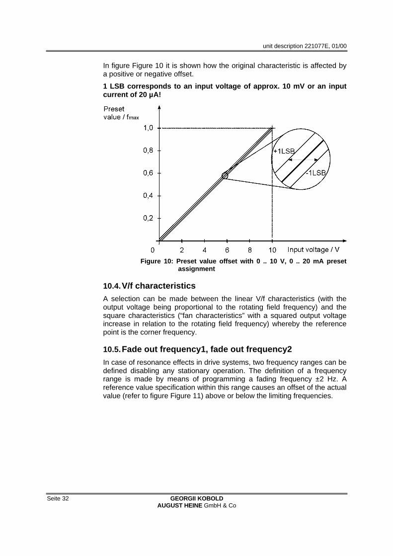
In figure Figure 10 it is shown how the original characteristic is affected bya positive or negative offset.
1 LSB corresponds to an input voltage of approx. 10 mV or an inputcurrent of 20 µA!
Figure 10: Preset value offset with 0 .. 10 V, 0 .. 20 mA presetassignment
10.4. V/f characteristicsA selection can be made between the linear V/f characteristics (with theoutput voltage being proportional to the rotating field frequency) and thesquare characteristics (“fan characteristics” with a squared output voltageincrease in relation to the rotating field frequency) whereby the referencepoint is the corner frequency.
10.5. Fade out frequency1, fade out frequency2In case of resonance effects in drive systems, two frequency ranges can bedefined disabling any stationary operation. The definition of a frequencyrange is made by means of programming a fading frequency ±2 Hz. Areference value specification within this range causes an offset of the actualvalue (refer to figure Figure 11) above or below the limiting frequencies.

unit description 221077E, 01/00
GEORGII KOBOLD Seite 33AUGUST HEINE GmbH & Co
Figure 11: Rotating fieled frequency using the fade outfrequencies


unit description 221077E, 01/00
GEORGII KOBOLD Seite 35AUGUST HEINE GmbH & Co
11. Programming of the digital inputs/outputsThe digital inputs and outputs of the KFU are programmable. They can beassigned to the converter functions mentioned in sections 9.
A special feature of the digital inputs is the programmability of amultifunctional terminal and four logical linking possibilities. Furthermore,the evaluation of the input signals at terminals 5, 6, 7, and 8 can beprogrammed independently of the function parameters (refer to figureFigure 12) by means of the "terminal assignment" parameter. A definable"reaction time" is used for the suppression of noise signals or bouncingtimes of switch contacts.
As described in section 9.4, it is required to display the menu for theparameterization of inputs/outputs.
11.1. Parameterization of the control inputsThe following functions can be applied to terminals 5, 6, 7, and 8. Theassignment of several functions to one input is possible (refer to section11.1).
(1) cw start
(2) ccw start
(3) parameter set changeover 0
(4) parameter set changeover 1
(5) f min
(6) f fix
(7) input reset
The logical linking and inversion of input terminals is defined as follows:
L Kl. 5 ---> non-inverted input (high active)
L INV 5 ---> inverted input (low active)
L OR 5+6 ---> logical OR non-inverted inputs
L INV 5+6 ---> logical OR inverted inputs
L AND 5&6 ---> logical AND non-inverted inputs
L INV 5&6 ---> logical AND inverted inputs
The following symbols are determined for terminal assignment:
L level-controlled input (high active)
L level-controlled input (low active)
L edge-controlled input (positive edge-triggering)
L edge-controlled input (negative edge-triggering)

unit description 221077E, 01/00
Seite 36 GEORGII KOBOLDAUGUST HEINE GmbH & Co
Figure 12: Configuration of the control inputs
11.2. Parameterization of the control outputsTerminals 15 and 16 (the relay output switches together with the opencollector output of terminal 6). The following functions can be assigned:
(1) multi-function (8) excess temperature 2
(2) PTC motor temperature (9) general fault message
(3) undervoltage (10) zero monitoring
(4) overvoltage 1 (11) DC braking
(5) overvoltage 2 (12) ready
(6) short-circuit (13) I²t error
(7) excess temperature 1 (14) digital output (only to terminal 15)
Furthermore, there is the possibility of inverting the outputs!

unit description 221077E, 01/00
GEORGII KOBOLD Seite 37AUGUST HEINE GmbH & Co
11.3. Explanations to the control inputs and outputsMinimum rotating field frequency
With a wired input, the minimum rotating field frequency is keptindependently of the set value.
Parameter set switching
The current parameter set is displayed in the ”Operating values” menu. Aparameter set desired by wiring the corresponding inputs is taken overonline.
Parameter setchangeover 0
Parameter setchangeover 1
Parameter set 1 active active
Parameter set 2 inactive active
Parameter set 3 active inactive
Parameter set 4 inactive inactive
Table 5: Parameter set changeover
Note: For parameter sets can be activated ba re-programming the inputsand using the parameter set changeover 1 function (Par1)
Clockwise rotation start (cw start)
If this input is wired and a positive set value is simultaneously applied themotor runs up to speed withthe running-up time specified in the selectedparameter set until the set value is reached and in the specified direction.
If the input is opened running-down is initiated using the set ramp of theselected parameter set up to the standstill. If the ramp of the correspondingparameter set is deactivated the shaft is immediately released.
Ccounter-clockwise rotation start (ccw start)
Refer to ´Clockwise rotation start´ with the opposite rotating direction. If´Clockwise rotation start´ is activated in addition, it has precedence (areversing procedure is made).
Fixed frequency
Immediate running-up/running-down to this preset value of thecorresponding parameter set, independent of the currently applied setvalue.
Note: The fixed frequency can be activated by re-programming the inputsand using the f fix function.

unit description 221077E, 01/00
Seite 38 GEORGII KOBOLDAUGUST HEINE GmbH & Co
Input reset
An active "input reset" function de-activates all input latches (refer tofigureFigure 12) and therefore all programmable functions exclusivelylinked to edge-controlled inputs.
Reset
Activating this input initializes the controller and the power circuit of theconverter. After this, the device is a ready to operate state.
If the input is opened the converter immediately releases the motor shaft.
PTC input
Motor protection or thermal protection as a switch
Analog output
Analog signal (0 -10V) corresponding to the current rotating field frequency.
at f max <= 127 Hz → 127 Hz = 10 V
at f max <= 250 Hz → 250 Hz = 10 V
Digital output (programmable function, refer to section 11.2)
Digital signal corresponding to the current rotary field frequency (0-250Hz).
Programmable digital outputs
Refer to section 11.2

unit description 221077E, 01/00
GEORGII KOBOLD Seite 39AUGUST HEINE GmbH & Co
12. Connection diagram
Table 6: Terminals, control stage, minimal required assignment
Pin Description Value
1 Reference voltage + 10 V-DC
2 Preset value input, analog/digital 0 .. 10 V-DC, 2 .. 10 V-DC
0 .. 20 mA, 4 .. 20 mA
0 .. 100 kHz
3 GND Ground
4 Reference voltage + 15 V-DC
5 Digital input ** min. rotating field frequency
6 Digital input * parameter set changeover 0
7 Digital input * ccw start
8 Digital input * cw start
9 Digital input Reset
10 GND Ground
11 Analog input PTC motor temp. monitoring
12 GND Ground
13 Analog output 0 .. 10 V-DC
* factory settings of the 4 programmable inputs

unit description 221077E, 01/00
Seite 40 GEORGII KOBOLDAUGUST HEINE GmbH & Co
14 External voltage input 12 .. 30 V-DC
15 Digital output 2 Programmable
16 Digital output 1 Programmable
17 Relais output NO-contact
18 Relais output common contact
19 Relais output NC-contact
Table 7: Terminal assignment, control stage
Note: The digital inputs (terminals 5, 6, 7, 8, 9) are designed for a controlvoltage range of 12 V up to 30 V!The open collector outputs ( terminals 15,16 ) can be loaded30V/40mA max.!The relay can be loaded 250V-AC/7A max. or 30 V-DC/7 A max.!
Figure 13: Terminal assignment, power stage
Pin Description Value
20 Input external braking resistor
21 Input external braking resistor
22 U
23 V
24 W
Umot 3 x 0 .. 230 V-AC
25 PE
26 PE
27 N
28 L1
Pin 47-49, KFU 8/230, KFU 10/230 only! Voltage output for fan.
47 PE
48 N
49 L1
Table 8: Terminal assignment, power stage

unit description 221077E, 01/00
GEORGII KOBOLD Seite 41AUGUST HEINE GmbH & Co
13. DimensionsKFU 2-230 DF3
KFU 4-230 DF3
KFU 8-230 DF3
KFU 10-230 DF3
a 65 mm 130 mm
b 220 mm 296 mm
c 230 mm 310 mm
d 70 mm 80 mm
e 112 mm 180 mm
f 50 mm 40 mm
g 204 mm 270 mm
s 5,5 mm 6 mm
Table 9: Dimensions
Casing with terminal compartment, prog. unit cable lockings.
Figure 14: Dimensions


unit description 221077E, 01/00
GEORGII KOBOLD Seite 43AUGUST HEINE GmbH & Co
14. Technical dataTyp KFU .../230-A-DF3 2 4 8 10
Device output power 0,88 kVA 1,6 kVA 3,2 kVA 3,9 kVA
Max. motor power 0,37 kW 0,75 kW 1,5 kW 2,2 kW
Rated output current 2,0 A 4,0 A 8,0 A 10,0 A
Max. rated output voltage 3 x 0 .. 230 V, PWM, sinusoidal
Max. rated output frequency 0 .. 250 Hz + 25%
Outputmotor side
Output choke internal
Rated voltage 400 V ±10%
Mains filter internalInputmain side
Mains frequency 50 /60 Hz ±10%
Protection class IP 20
Resolution analog input 212 Bit at 0 .. 10 V, 26 Bit
Max. voltage rising time 4 kV/µs
Mean operating hours ~100 000 h
Max. surface temperature 55 °C
Environmental temerapure 0 - 50 °C
Environmentaly humidity 20 - 90% rel.
General data
Weight 1,8 kg
Table 10: Technical Data


unit description 221077E, 01/00
GEORGII KOBOLD Seite 45AUGUST HEINE GmbH & Co
15. Application notes
15.1. Dynamic braking using a braking chopperThe built-in braking chopper with external braking resistor enables dynamicbraking of large masses without initiating a switch-off of the converter.
When braking centrifugal masses with a relatively short running-down time(brake time), the mass inertia of the entire drive works as generatorictorque.
This braking operating is equivalent to an energy feedback of the driveresulting in a temporary circuit voltage increase up to the point where theexcessive voltage switch-off is initiated. By routing this braking energy intoa resistor, the switching off can be prevented. The braking choppercompares the temporary circuit voltage with a reference voltage which hasa voltage level below the over-voltage tripping level. When the referencevoltage is exceeded a power transistor connects the braking resistor to thetemporary circuit voltage. The resistor then converts the power generatedby the motor in heat loss.
The braking power can be calculated with reference to the activation time(ED) of the braking resistors. Thus the breaking chopper can be individuallyadapted to the drive.
Recommendations for the selection of brake resistors:
The used resistors must be suited for the current and peak power. Theelectrical strength of the resistors must be 1000 V.
The necessary mean brake power is calculated from the peak power andthe on-time of the chopper.
power(W)peaktime(s)cycle
ED(s)durationtimeonpower(W)Nom. ∗
−=
In practice it showed that for most applications resistors with a nominalcontinuous power loss of 60 Watts are sufficient.
KFU .. / 230 Resistor Peak power I max
2 100 Ohm 1 kW 2.5 A
4 100 Ohm 1 kW 2.5 A
8 100 Ohm 1.5 kW 3.7 A
10 100 Ohm 1.5 kW 3.7 A
Table 11: Spezification of braking resistors

unit description 221077E, 01/00
Seite 46 GEORGII KOBOLDAUGUST HEINE GmbH & Co
15.2. Motor protectionDespite using high-grade sine modulation when powering standard 3-phaseasynchronous motors additional losses occur in the motor. Even at nominalrevolutions these losses incur a power reduction whose extent dependsessentially on the exploitation of the temperature ranges of the motor.
For drives with a square counter-torque (e.g.fans) and 50 Hz as maximumrotating field frequency the imposed power reduction is usually around 0 -10%.
For drives with a constant counter-torque (compressors, conveyer belts,etc.), the power reduction has to be selected correspondingly largerdepending on the range of the adjustment.
For the adjustment range,the stationary load torque must lie below thecontinuous operating characteristics of the motor to guarantee a safeoperation of a motor. During operation and starting of the drive, it able tomomentarily submit torques corresponding to the current limiting of theconverter. The setting of the voltage increase (static Boost). essentiallydetermines the maximum torque below 10 Hz. During a continuousoperation an excessive high boost setting for the lower rotating fieldfrequency range (up to 15 Hz) can cause an overheating of the motor.
An all-including thermal protection of the self-cooling motor can beachieved by means of a temperature sensor (e.g. PTC thermistor orthermal time-delay switch) built into the motor. For revolutions above 120%of the nominal revolutions, the performance of the motor has to beexamined.
Figure 15: Operating characteristics of a frequency-controlledasynchronous machine

unit description 221077E, 01/00
GEORGII KOBOLD Seite 47AUGUST HEINE GmbH & Co
15.3. Cabinet mounting
Figure 16: Cabinet mounting
15.4. Measures for securing the EMCSubsequently measures for guaranteeing the electromagnetic compatibilityare presented which are to be regarded as an imperative necessity in thearea of the converter technology.
Grounding, earthing, potential compensation
The correct, professional grounding or earthing guarantees the personnelprotection against dangerous touch voltages (input, output and intermediatecircuit voltage). Spill current diverting and low-impedance potentialcompensation are important measures for reducing electromagneticinfluences.
unit description 221077E, 01/00
Seite 48 GEORGII KOBOLDAUGUST HEINE GmbH & Co
Filtering
Filters are inserted into the lead-bound transfer way between interferencesource and interference susceptible equipment. Their task is to reducelead-bound transmissions as well as to increase the noise immunity.Therefore, the KFU mainsfilter and output chokes have been built-in.
Screening
Screening is used for decoupling fields of two spatial areas, i.e. it also usedto decrease the emission of electromagnetic radiation and to increase thenoise immunity. The consistent use of metal cases (KFU) shows one of themost important standard measures for guaranteeing the EMC.
Coupling into motor cables
Using twisted core cables can essentially reduce couplings into a circuit.Capacitive, inductive and electromagnetic interferences are reduced byusing cable screens. Note that for reducing low frequency capacitiveinterference, generally a one-sided connection of the screening may besufficient. Inductive and high frequency electromagnetic interference can beprevented only by connecting both sides of the cable screening.
The screening must not be used as protection earthing!!!
15.5. WarningsAccording to the newest state of the technology, electronical powercontrollers are operating-safe electrical equipment for use in all heatengineering equipment.
!! Please take special note of safety remarks!!
Caution:
Perform work on the controllers, e.g. assembly, connection, maintenanceonly if
L the electric equipment is voltage-free
L protected against powering up, and
L all drives are standing still
Danger:
In the power-up state, electrical equipment and machines have voltage-leading and non-isolated conductors or rotating parts. After removing theoperation covers and mandatory protection facilities, those wires androtating parts can cause personnel insuries and property damages whentreated and maintained wrongly and/or at non-intended use.
There is an additional danger connected with power electronical devicessince it is not necessarily known by every skilled worker that the equipmentmight still be under voltage even after switching off of the supply voltage(capacitor chargement!). In addition for the awaiting of the discharge time(approx. 90 sec.), the residual voltage must be checked before starting thework.

unit description 221077E, 01/00
GEORGII KOBOLD Seite 49AUGUST HEINE GmbH & Co
Attention:
Only skilled workers who master the respectively valid safety regulationsand assembly instructions are allowed to
L transport,
L set up,
L connect,
L commission,
L maintain, and
L operate
electric equipment and machines.
The safety-legal responsible of the equipment must authorize the skilledworkers for the necessary activities.
Skilled workers are persons that
L are educated and experienced.
L master the respective valid standards, regulations, determinations andaccident prevention instructions.
L have been introduced to the method of functioning and operatingconditions of electric motion systems.
L can recognize and avoid dangers.
For the regulation concerning skilled workers
refer to VDE 0105 or IEC 364.
The use of non-qualified personnel is forbidden.
The controller and interlocks as well as the monitoring and protectionfunctions (rotational speed monitoring, excess current a.s.o.) may not beoverridden or made functionless also not during the test operation.
Equipment may only be assembled and operated in the documented order.Intended use! Each other usage is not admissible!
Storage regulations:
The instructions for the storing of electric equipment are to be observed.Please request more information if required and/or take these from thespecifications!
Prevent noise and thereby avoid personnel and property damages.
The responsible for the equipment must ensure that safety notes andoperating instructions are at hand and are observed,
L operating conditions and specifications according to the order areobserved,

unit description 221077E, 01/00
Seite 50 GEORGII KOBOLDAUGUST HEINE GmbH & Co
L protection facilities are used,
L prescribed maintenance work is performed,
L the maintenance personnel are immediately notified or the electricequipment is immediately stopped if higher temperatures, noise,oscillations etc. appear in contrast to the rated operation.
Information are contained in the operating instruction which are required byskilled workers for using the electrical equipment in industrial equipment.Additional information and notes for non-qualified personnel, for using theequipment in non-industrial equipment, and about possible drive variantsare not contained in this operating manual.
A guarantee of the manufacturer is only maintained when observing andmaintaining the respectively valid operating instructions