Digital - Fastly · Email:[email protected] RepublicofIreland Salesenquiries:01-864-3363...
13
Digital Shower head systems Installation guide Shower head systems installation instructions Page 1
Transcript of Digital - Fastly · Email:[email protected] RepublicofIreland Salesenquiries:01-864-3363...

DigitalShower head systems
Installation guide
Shower head systems installation instructions Page 1

Quartz Digital rail systemiSys Digital rail system
Quartz and iSys Digital Drencher heads
Shower head systems installation instructions Page 2
Shower head systems

Shower head systems installation instructions Page 3
Installation instructions
This product must be installed by a competent person in accordance with the relevant Water Supply
Regulations.
In addition to the guide below, it is essential that the written instructions in the main product
installation instructions are read and understood, and that you have all the necessary components
(shown in the main product installation guide) before commencing installation.
The shower head and rail kit is supplied complete with a 2 year guarantee.
The shower arm and rail kit is supplied with universal fixings intended to secure it to a suitable wall.
Please follow the main product installation instructions to fit the shower controller and processor/
diverter units (depending on product purchased) prior to installing the shower head and rail kit.
!
!
!
!
Adjustable height head
Ensure the finished wall surface is even, prepare pipework from the processor or diverter to the required
position for the hose outlet using a Ø15mm copper pipe. Slide the wall spacer down the projecting pipe
flush with the finished wall surface.
1
Slide the 15mm gripper ring down the projecting pipe flush with
the wall spacer fitting.2
Trim the projecting pipe to a length of 15-22mm, measured from the face of the gripper ring, using
a rotary type cutter. If a hacksaw is used, the pipe end must be carefully de-burred and chamfered.3

Shower head systems installation instructions Page 4
Clean and lubricate the pipe using a suitable (silicone based) lubricant.4
Remove the locking screw, rotate the chrome outlet assembly and
remove the outlet from the wall mounting plate.5
Ensuring the locking screw hole is positioned at the bottom, place the
wall outlet mounting plate onto the pipe assembly and mark and
prepare the fixing points, using the fixings provided, if suitable.
6
Ensuring the locking screw hole is positioned at the bottom, secure the wall mounting plate to the wall
using the screws provided, if suitable.7
Ensuring the O-ring is in the correct position on the mounting plate spigot, place the wall outlet
onto the mounting plate in the 5 o’clock position and rotate clockwise until a stop is reached.8
Refit the locking screw taking care not to overtighten.9

Shower head systems installation instructions Page 5
Prepare two fixing points between 520mm (minimum) and 830mm
(maximum) apart using the fixings provided, if suitable.10
The top rail end bracket can be adjusted to suit existing screw holes in the finished wall by sliding the
bracket up or down the rail to suit the required position.!
Pass the rail through the handset holder while keeping the slider
levers depressed.11
Carefully slide the gel hook onto the rail under the handset holder.12Current Water Supply Regulations state that the handset should not be allowed to pass a point 25mm
above the spill over level of the bath or shower tray. If this cannot be achieved, the hose must be passed
through the gel hook which has been designed to be utilised as a hose restraint.
!
Secure the top rail bracket into position using the screws provided,
if suitable.13
Attach the bottom rail end body onto the rail.14

Shower head systems installation instructions Page 6
Slide the rail assembly up through the top rail end body.15
Align the small hole in the rail with the bottom rail end fixing point. Secure the rail assembly to the
wall, using the fixings provided, if suitable, taking care to not over tighten.16
Place the rail end caps into the rail ends and push firmly into
position.17
Pass the hose through the gel hanger.18
Ensuring the hose washer is in the correct position, secure the
handset to the hose then place the handset into the handset holder.
N.B. If fitting the Quartz handset, depress the anti-swivel locking
button on the handset whilst securing the handset to the hose.
19
Shower head systems installation instructions Page 7
Ensuring the hose washer is in the correct position; attach the hose to
the wall outlet.20
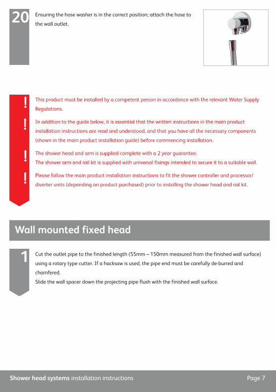
Wall mounted fixed head
Cut the outlet pipe to the finished length (55mm – 150mm measured from the finished wall surface)
using a rotary type cutter. If a hacksaw is used, the pipe end must be carefully de-burred and
chamfered.
Slide the wall spacer down the projecting pipe flush with the finished wall surface.
1
This product must be installed by a competent person in accordance with the relevant Water Supply
Regulations.
In addition to the guide below, it is essential that the written instructions in the main product
installation instructions are read and understood, and that you have all the necessary components
(shown in the main product installation guide) before commencing installation.
The shower head and arm is supplied complete with a 2 year guarantee.
The shower arm and rail kit is supplied with universal fixings intended to secure it to a suitable wall.
Please follow the main product installation instructions to fit the shower controller and processor/
diverter units (depending on product purchased) prior to installing the shower head and rail kit.
!
!
!
!

Shower head systems installation instructions Page 8
Slide the 15mm gripper ring down the projecting pipe flush with
the wall spacer fitting.2
Ensure the pipe is clean and free of dust and slide the fixing bush
onto the pipe flush with the finished wall surface.3
Slide the fixed head arm over the fixing bush flush with the wall surface and mark the four fixing
points.4
Carefully remove the fixed head arm and drill and prepare the fixings using the fixings provided,
if suitable, taking care to avoid pipework hidden in the wall.5
Ensuring the fixing bush is clean and free of dust, fit the 15mm O-ring
against the end of the fixing bush. Lubricate the O-ring using a suitable
silicone based lubricant.
6
The O-ring must be positioned on the 15mm pipe flush to the fixing
bush, not onto the fixing bush shaft.!
Shower head systems installation instructions Page 9
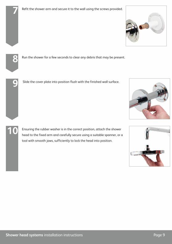
Refit the shower arm and secure it to the wall using the screws provided.7
Run the shower for a few seconds to clear any debris that may be present.8
Slide the cover plate into position flush with the finished wall surface.9
Ensuring the rubber washer is in the correct position, attach the shower
head to the fixed arm and carefully secure using a suitable spanner, or a
tool with smooth jaws, sufficiently to lock the head into position.
10

Shower head systems installation instructions Page 10
Ceiling mounted fixed head
Run a 15mm outlet pipe from the processor/diverter to the preferred position for the fixed head.1
This product must be installed by a competent person in accordance with the relevant Water Supply
Regulations.
In addition to the guide below, it is essential that the written instructions in the main product
installation instructions are read and understood, and that you have all the necessary components
(shown in the main product installation guide) before commencing installation.
The shower head and arm is supplied complete with a 2 year guarantee.
The shower arm and rail kit is supplied with universal fixings intended to secure it to a suitable wall.
Please follow the main product installation instructions to fit the shower controller and processor/
diverter units (depending on product purchased) prior to installing the shower head and rail kit.
!
!
!
!
The ceiling mounted fixed head is supplied with screws for fixing the product to a noggin.
A NOGGIN MUST BE USED AS PART OF THIS INSTALLATION.!
Locate the position for the fixed head in the bathroom and firstly drill a
pilot hole to mark the position before checking that there is suitable
space behind the ceiling for the fixing assembly.
2
The minimum height required behind the ceiling is 50mm and the space must allow for an 80mm wide,
50mm deep noggin to be used to support the assembly.!

Shower head systems installation instructions Page 11
Drill a hole (minimum ø28mm, maximum ø40mm) through the ceiling and the noggin.3
Remove the fixing bracket carefully from the fixed head arm.4
Set the fixing bracket into position and mark the fixing points. Remove
the bracket and drill and prepare suitable fixings. Refit the fixing
bracket and secure it through the ceiling and into the noggin using
the screws provided if suitable.
5
Feed the arm through the fixing bracket to the correct depth.
Tighten the nut using a 32mm spanner if necessary to facilitate.6
Cut off the excess pipe allowing for a suitable working length to allow for the required 22mm
connection. If a push fit connector is to be used then the pipe must be abraded to remove all
chrome plating.
7
Connect the pipe work from the valve, diverter or processor to the end of the fixed head
pipe using a suitable coupling.8
Run the shower for a few seconds to clear any debris and to check for any leaks.!

Shower head systems installation instructions Page 12
Lubricate the ‘O’ ring if necessary and carefully
slide the cover plate back over the fixed head arm
and into position against the ceiling.
9
Secure the cover plate to the arm using the grub screw
and 2.5mm hexagonal key provided.10
Ensuring the rubber washer is in the correct position,
attach the shower head to the fixed arm and carefully
secure using a suitable spanner, or a tool with smooth
jaws, sufficiently to lock the head into position.
11

Aqualisa Products Limited
The Flyer’s Way
Westerham Kent TN16 1DE
Customer helpline: 01959 560010
Brochure Hotline: 0800 652 3669
Website: www.aqualisa.co.uk
Email: [email protected]
Republic of Ireland
Sales enquiries: 01-864-3363
Service enquiries: 01-844-3212 Part No:700997 Issue 01 Jan 14
Please note that calls may be recorded for training and quality purposes
The company reserves the right to alter, change or modify the product specifications without prior warning
® Registered Trademark Aqualisa Products Limited