Replacement SideControl type 1067 NAMUR IEC 534 / VDI - Burkert

1/20www.burkert.com
8792
can be combined with…e
The robust and compact positioner is
designed to standardisation acc. to IEC
or I E IEC
for assembly with linear and rotary actua-
tors. In addition, the remote version with the
displacement position sensor can be com-
bined with Bürkert process control valves.
The digital electropneumatic positioner
SideControl can be operated with the usual
current and voltage standard signals and
can also be e uipped with the eldbus in-
terface. The Positioner is equipped with ad-
ditional diagnostic functions to monitor the
state of the valve. Through status signals,
valve diagnostic messages are transmitted
according to E recommen-
dations and recorded as history. With the
diagnosis, the operating conditions of the
control valve can be monitored. This allows
planned maintenance and optimises plant
availability. Operation occurs via the external
operation and display module with a backlit
graphical display. The user operation is very
simple and clear, identical to the Bürkert
positioner or process controller TopControl,
Type . The pilot valve system can
be used equally for single and double-acting
actuators. It is characterised by a de ned
safety feature in case of failure of the electri-
cal or pneumatic power supply and pos-
sesses an enormous air capacity range with
pressure supply up to bar.
• Compact and robust design
• Easy to start using Tune function
• Integrated diagnostic functions for valve monitoring
• Dynamic positioning system with no air consumption in con-trolled state
• PROFIBUS DP-V1, DeviceNet, EtherNet/IP, PROFINET, Modbus TCP or büS Bürkert System Bus
Digital electropneumatic Positioner SideControl
Technical data
MaterialBody Seal
Aluminium plastic-coatedEPDM, NBR, FKM
Operating voltages V DC 1
Residual ripple Max. 1
Setpoint setting / … mA and … /1 V
Input resistance / … mA 1 … /1 V 1 k
Analogue feedback … mA, … mA0 … 10 V, 0 … 5 V
Binary input Galvanically isolated, 0 … 5 V = log "0", 10 … 30 V = log "1"
Binary outputCurrent limit
Outputs optional , galvanically separated100 mA, Output will be synchronised when overloaded
Control mediumDust concentrationParticle densityPressure condensation pointOil concentration
neutral gases, air, quality classes acc. to ISO 5 3-1Class 0 m particle si eClass 5 10 mg/m3
Class 3 - 0 CClass 5 mg/m3
Ambient temperature - 10 to 0 C without Ex-Approval 0 to 0 C with ATE / IECEx-Approval
Pilot air ports Threaded ports G ¼
Supply pressure 1. … bar1
Air supply lter Exchangeable aperture si e 0.1 mm
Actuator system Air capacity
Single and double-acting to 150 lN/min.
50 lN/min with 1. bar for aeration and ventilation
150 lN/min with bar for aeration and ventilation
Nn = 100 l
N/min acc. to the de nition with decrease in
pressure from … bar absolute
Position detection module Potentiometer, max. angle 1 0
Stroke range valve spindle Min. 30 on the rotary shaft, depending on lever
Installation As required, display above or sideways
continued on next page
1 The supply pressure has to be 0.5 … 1 bar above the minimum required pilot pressure for the valve actuator
Pressure speci cations Overpressure with respect to atmospheric pressure
Yoke type actuators Rotary actuators with
remote positioner
Hygienic process
control valve with
remote positioner
Rotary
actuators
Process control
valve with remote
positioner

8792
2/20
Technical data, continued
Technical data
Type of protection IP 5/IP acc. to EN 05 , Type acc. to NEMA 50 standard
Power consumption 5 W
Electrical connectionMultipole connectionCable gland
Remote version
M1 , pin/ pin M , pinx M 0 1.5 cable … 1 mm on screw terminals
0.1 … 1.5 mm 1x M1 1.5 cable 3 … .5 mm
Bus communication PROFIBUS DP-V1, DeviceNet, EtherNet/IP, PROFINET, Modbus TCP or büS based on CANopen
Protection class III acc. to DIN EN 61140
Conformity EMC directive 014/30/EU
CSA approval informationProduct category code
Class 3 1 -VA VES - Actuators - Certi ed to US standards
Class 3 1 0 -VA VES - Actuators
Considered standards CAN/CSA-C No. 13U 4
CSA trademark
Ex-Approval ATEX IECEx
II 3G Ex ec ic IIC T4 Gc / II 3D Ex tc IIIC T135 C DcCerti cate BVS 16 ATE E 11 Ex ec ic IIC T4 Gc / Ex tc IIIC T135 C DcCerti cate IECEx BVS 16.00 1
Technical data - Linear Remote Position Sensor (ELEMENT)
Electrical connectionCable glandConnection cable length
1x M16 1.5 cable 5 … 10 mm on terminal screws 0.14 … 1.5 mm 10 m
Operating voltage 4 V DC 10
Power consumption 0.3 W
Sensor measurement range 3 … 45 mm Stroke range valve spindle
Actual position signal digital RS4 5
Ambient temperature - 5 to 0 C
Protection class III acc. to DIN EN 61140
Type of protection IP65 and IP6 acc. to EN 605 , Type 4 acc. to NEMA 50 standard
Type of Ignition protection II 3D Ex tc IIIC T135 C Dc II 3G Ex nA IIC T4 Gc
Conformity EMC directive 014/30/EU
Approvals cU us Certi cate no. 3 1
Using a remote positioner the length of the control air pipes in uences the dynamics and
attainable accuracy of the position control loop. The length of the control air pipes therefore
should be as short as possible.
Technical data - Position feedback with proximity switches (Accessory)
Electrical connection M1 , 4 pin
Output function 3-wire, normally open contact, PNP
Operating voltage 10 … 30 V DC
Residual ripple 10 Uss
DC rated current 100 mA
Type of protection IP65 and IP6
Protection class III acc. to DIN EN 61140
Conformity EMC directive 014/30/EU
Approvals cCSAus
Note The position feedback has two
proximity switches which are indepen-
dently adjustable via switch lugs.
Technical data - rotative Remote Position Sensor (NAMUR)
Electrical connection m round cable shielded
Operating voltage 10 … 30 V DC
Residual ripple 0. W
Sensor measurement range 0 to 360
Actual position signal digital RS4 5
Ambient temperature - 5 to 0 C
Protection class III acc. to DIN EN 61140
Type of protection IP65 acc. to EN 605
Conformity EMC directive 014/30/EU
Approvals U cU us Certi cate no. E 6 0

8792
3/20
Example of assembly variations of positioner SideControl
Positioner SideControl Type 8792
Linear actuators
IEC 60534-6-1
Rotary
actuators
VDI/VDE 3845
(IEC 60534-6-2)
Type 8798
Sensor Remote
NAMUR
+
Type 8792
Remote
Linear actuators
IEC 60534-6-1
Rotary
actuators
VDI/VDE 3845
(IEC 60534-6-2)
Type 8805
+
Type 8792
Control valve
system
Type 2300
+
Type 8798
Remote
Position
Sensor
+
Type 8792
Remote
8792 NAMUR 8792 Remote
Positioner 8792

8792
4/20
Description Article no.
Position feedback 6 1
Assembly options
NAMUR Version (Positioner with integrated position sensor, assembly acc. to NAMUR/IEC 60534-6-1 and VDI/VDE 3845 (IEC 60534-6-2))
Assembly on linear actuator
Dimensions [mm]
Adapter kit
Ø15
B B
9
23
A
Ø8+0.1
16
B-B
4
4
4
1
2
3
4
5
Assembly on rotary actuator
Assembly bridge
( B )
A
107,6
C
30
50
R7
19,5
R34
External position indicator
Coverfor standard display element
Housing cover
Connecting external position indicator
Actuator shaft height
A B C
20 46.5 80 -
30 56.5 80 130
50 76.5 - 130
Position feedback with proximity switches (upgrade feature for SideControl NAMUR)
Description Article no.
Adapter kit 787338
Assembly bridge 770294
Description Article no.
Adapter kit 787215

8792
5/20
Assembly on DIN-Rail
12
013
1.5
30
3
19
6.1
33
Dimensions [mm]
Dimensions [mm]
36
45
Ø4
.7174
368.5
10.5
12
8.5
65
Assembly options continued
Remote version(Displaced positioner with external remote position sensor)
Assembly with accessory brackets
73
48
36.3
68
6
14
10.3
The adapter
can be turned
every 90 on
the DIN-Rail
4 90
Description Article no.
Assembly bracket for wall mounting 675715
Description Article no.
DIN rail assembly kit 675702

8792
6/20
Assembly options continued
Remote version(Remote position sensor for displaced positioner)
Type 8798
Dimensions
For mounting on Control valves ELEMENT Types 23xx
99.5Ø91
114
17
,1
11
9
Description Article no.
Remote Position SensorNAMUR
211536
Description Article no.
Standard ATEX II 3 GD
Remote Position SensorMounting on control valves Type 23xx 212360 226860
Mounting on control valves Type 27xx 211535 226859
8792
7/20
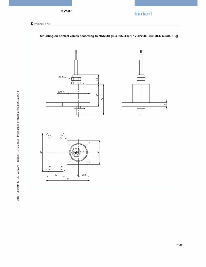
Dimensions
36.1
64 4
6
20 SW 17
91
80
50
40 23.5 5
8
Mounting on control valves according to NAMUR (IEC 60534-6-1 / VDI/VDE 3845 (IEC 60534-6-2))
8792
8/20
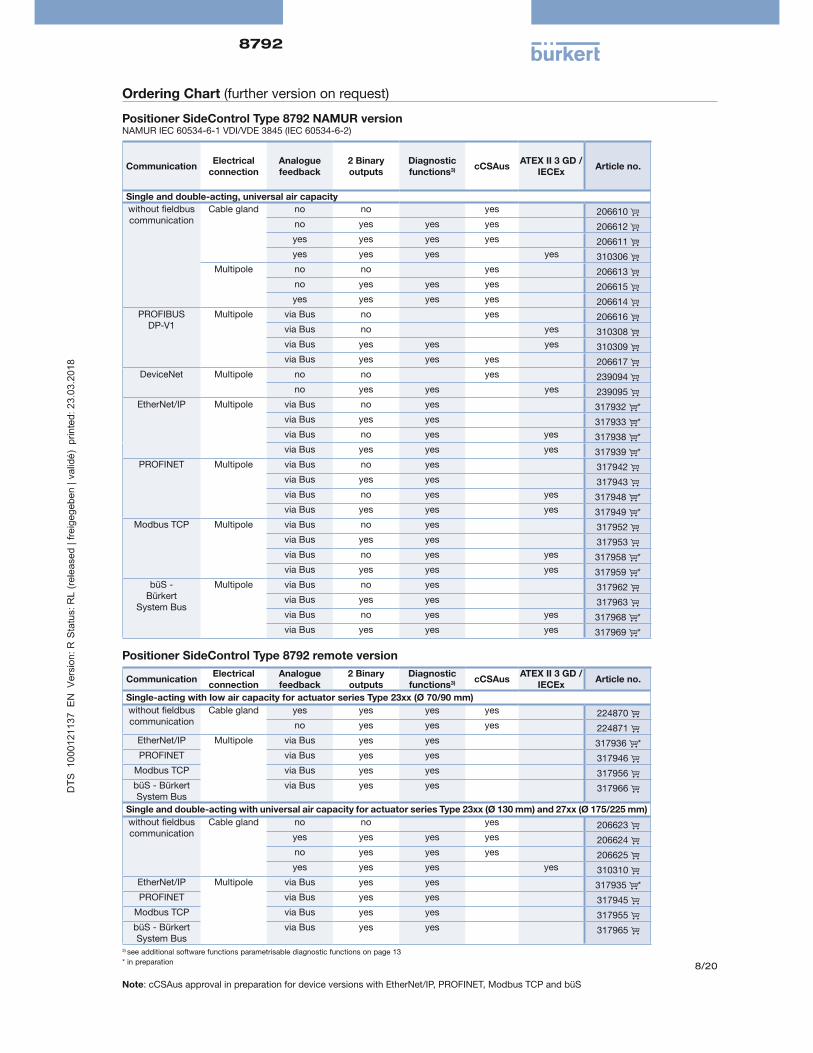
Ordering Chart (further version on request)
Positioner SideControl Type 8792 NAMUR versionNAMUR IEC 60534-6-1 VDI/VDE 3845 (IEC 60534-6-2)
Communi cationElectrical
connectionAnalogue feedback
2 Binary outputs
Diagnostic functions3) cCSAus
ATEX II 3 GD / IECEx
Article no.
Single and double-acting, universal air capacity
without eldbus communication
Cable gland no no yes 206610
no yes yes yes 206612
yes yes yes yes 206611
yes yes yes yes 310306
Multipole no no yes 206613
no yes yes yes 206615
yes yes yes yes 206614
PROFIBUS DP-V1
Multipole via Bus no yes 206616
via Bus no yes 310308
via Bus yes yes yes 310309
via Bus yes yes yes 206617
DeviceNet Multipole no no yes 239094
no yes yes yes 239095
EtherNet/IP Multipole via Bus no yes 317932 *
via Bus yes yes 317933 *
via Bus no yes yes 317938 *
via Bus yes yes yes 317939 *
PROFINET Multipole via Bus no yes 317942
via Bus yes yes 317943
via Bus no yes yes 317948 *
via Bus yes yes yes 317949 *
Modbus TCP Multipole via Bus no yes 317952
via Bus yes yes 317953
via Bus no yes yes 317958 *
via Bus yes yes yes 317959 *
büS - Bürkert
System Bus
Multipole via Bus no yes 317962
via Bus yes yes 317963
via Bus no yes yes 317968 *
via Bus yes yes yes 317969 *
Positioner SideControl Type 8792 remote version
Communi cationElectrical
connectionAnalogue feedback
2 Binary outputs
Diagnostic functions3) cCSAus
ATEX II 3 GD / IECEx
Article no.
Single-acting with low air capacity for actuator series Type 23xx (Ø 70/90 mm)
without eldbus communication
Cable gland yes yes yes yes 224870
no yes yes yes 224871
EtherNet/IP Multipole via Bus yes yes 317936 *
PROFINET via Bus yes yes 317946
Modbus TCP via Bus yes yes 317956
büS - Bürkert System Bus
via Bus yes yes 317966
Single and double-acting with universal air capacity for actuator series Type 23xx (Ø 130 mm) and 27xx (Ø 175/225 mm)
without eldbus communication
Cable gland no no yes 206623
yes yes yes yes 206624
no yes yes yes 206625
yes yes yes yes 310310
EtherNet/IP Multipole via Bus yes yes 317935 *
PROFINET via Bus yes yes 317945
Modbus TCP via Bus yes yes 317955
büS - Bürkert System Bus
via Bus yes yes 317965
3) see additional software functions parametrisable diagnostic functions on page 13
* in preparation
Note cCSAus approval in preparation for device versions with EtherNet/IP, PROFINET, Modbus TCP and büS

8792
9/20
Ordering chart for accessories
Description Article no.
Accessories for SideControl NAMUR
Assembly bridge VDI/VDE 3845 (IEC 60534-6-2), stainless steel 770294
Adapter kit VDI/VDE 3845 (IEC 60534-6-2), stainless steel 787338
Adapter kit linear actuators IEC 60534-6-1, stainless steel 787215
Position feedback with proximity switches (optional upgrade feature) 3) 677218
Accessories for SideControl Remote
Bracket for wall mounting, stainless steel 675715
DIN rail assembly kit, Aluminium/stainless steel 675702
Adapter kit - remote sensor control valves Type 23xxActuator si e Ø 70/90/130 mm 679917
Adapter kit - remote sensor control valves Type 27xx Actuator si e Ø 175 / 225 mm
679945
Sensor Puck (replacement part) 682240
Standard Accessories
M12 socket 8 pin with 5 m cable for power supply and input/output signals 919267
M8 plug 4 pin for binary outputs, with solder joints 917131
USB büS-Interface Set (büS-Stick + connection cable with M12 plug + conection cable M12 on micro USB for the büS service interface) to connect with PC-Tool Bürkert Communicator (only for device versions with EtherNet/IP, PROFINET, Modbus TCP and büS - Bürkert System Bus)
772551
büS cable extension M12, length 1 m 772404
büS cable extension M12, length 3 m 772405
büS cable extension M12, length 5 m 772406
büS cable extension M12, length 10 m 772407
SIM card 291773
Silencer G ¼" (replacement part) 780780
Sensor puck (replacement part) 682240
USB interface for serial communication (only for device versions with PROFIBUS / DeviceNet or without eldbus communication)
227093
Software Bürkert Communicator http //www.buerkert.de/de/type/8920
* Related Communication software can be downloaded from www.buerkert.com (8792)3) External end position feedback for upgrading SideControl NAMUR
Ordering Chart, continued
Remote Position Sensor for SideControl Type 8792 remote version
Assembly variations Electrical connection cULus ATEX II 3 GD / IECEx Article no.
Control valve Type 23xx Cable gland - 10 m round cable yes no 212360
Cable gland - 10 m round cable no yes 226860
Control valve Type 27xx Cable gland - 10 m round cable yes no 211535
Cable gland - 10 m round cable no yes 226859
NAMUR (rotative) Cable gland - 2 m round cable (max. extension 10 m)
yes no 211536
8792
10/20
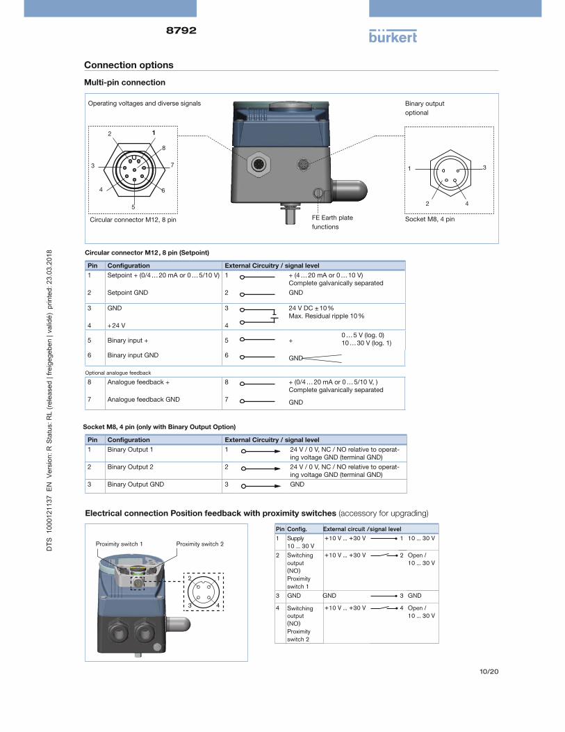
Connection options
Multi-pin connection
Pin Con guration External Circuitry / signal level
1 Setpoint + (0/4 … 20 mA or 0 … 5/10 V) 1 + (4 … 20 mA or 0 … 10 V) Complete galvanically separated
2 Setpoint GND 2 GND
3 GND 3 24 V DC 10 Max. Residual ripple 10
4 + 24 V 4
5 Binary input + 5 +0 … 5 V (log. 0)10 … 30 V (log. 1)
6 Binary input GND 6 GND
Optional analogue feedback
8 Analogue feedback + 8 + (0/4 … 20 mA or 0 … 5/10 V, ) Complete galvanically separated
7 Analogue feedback GND 7 GND
Pin Con guration External Circuitry / signal level
1 Binary Output 1 1 24 V / 0 V, NC / NO relative to operat-ing voltage GND (terminal GND)
2 Binary Output 2 2 24 V / 0 V, NC / NO relative to operat-ing voltage GND (terminal GND)
3 Binary Output GND 3 GND
Circular connector M12 , 8 pin (Setpoint)
Socket M8, 4 pin (only with Binary Output Option)
Socket M8, 4 pinCircular connector M12, 8 pin FE Earth plate
functions
Operating voltages and diverse signals
12
3
4
5
6
7
Binary output
optional
42
1 3
Electrical connection Position feedback with proximity switches (accessory for upgrading)
Proximity switch 1 Proximity switch 2
1
43
2
Pin Config. External circuit /signal level1 Supply
10 ... 30 V+10 V ... +30 V 1 10 ... 30 V
2 Switchingoutput(NO) Proximityswitch 1
+10 V ... +30 V 2 Open / 10 ... 30 V
3 GND GND 3 GND
4 Switchingoutput(NO) Proximity switch 2
+10 V ... +30 V 4 Open / 10 ... 30 V
8
8792
11/20
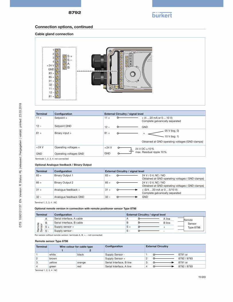
Connection options, continued
Cable gland connection
1
2
3
4
+ 24 V
GND
83 +
85 +
31 +
32
11 +
12
81 +
S + S A B
Terminal Con guration External Circuitry / signal level
11 + Setpoint + 11 + + (4 … 20 mA or 0 … 10 V) Complete galvanically separated
12 Setpoint GND 12 GND
81 +
Binary input +
81 +
Obtained at GND operating voltages (GND clamps)
+ 24 V
GND
Operating voltages +
Operating voltages GND
Terminals 1, 2, 3, 4 not connected
+05 V (log. 0)
10 V (log. 1)
+ 24 V
GND
24 V DC 10 max. Residual ripple 10
Terminal Con guration External Circuitry / signal level
83 + Binary Output 1 83 + 24 V / 0 V, NC / NO Obtained at GND operating voltages ( GND clamps)
85 + Binary Output 2 85 + 24 V / 0 V, NC / NO Obtained at GND operating voltages ( GND clamps)
31 + Analogue feedback + 31 + + (0/4 … 20 mA or 0 … 5/10 V) Complete galvanically separated
32 Analogue feedback GND 32 GND
Optional Analogue feedback / Binary Output
Terminal 1, 2, 3, 4 NC
Terminal Wire colour for cable type Con guration External Circuitry
1 2
1 white black Supply Sensor - 1 8791 or
2 brown Supply Sensor + 2 8792 / 8793
3 yellow orange Serial Interface, B line 3 8791 or
4 green red Serial Interface, A line 4 8792 / 8793
Remote sensor Type 8798
Terminal 1, 2, 3, 4 NC
Optional remote version in connection with remote positioner sensor Type 8798
Terminal Con guration External Circuitry / signal level
Rem
ote
S
enso
r
A Serial interface, A cable A A line
B Serial interface, B cable B B line
S + Supply sensor + S + +
S - Supply sensor - S - -
Remote
Sensor
Type 8798
For version without remote version terminals A, B, +, - not connected
8792
12/20
Connection options, continued
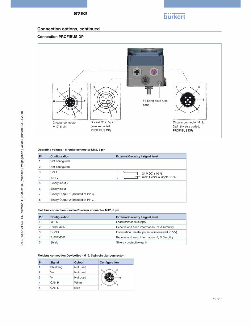
Connection PROFIBUS DP
8
1
2
3
4
5
6
7
Circular connector
M12, 8 pin
Circular connector M12,
5 pin (inverse coded,
PROFIBUS DP)
1
43
2
5
Socket M12, 5 pin
(inverse coded
PROFIBUS DP)
FE Earth plate func-
tions
2
34
1
5
Pin Con guration External Circuitry / signal level
1
2
Not con gured
Not con gured
3
4
GND
+ 24 V
5
6
Binary input +
Binary input
7
8
Binary Output 1 (oriented at Pin 3)
Binary Output 2 (oriented at Pin 3)
3
4
24 V DC 10 max. Residual ripple 10
Operating voltage - circular connector M12, 8 pin
Pin Con guration External Circuitry / signal level
1 VP+ 5 oad resistance supply
2 RxD/TxD-N Receive and send information -N, A Circuitry
3 DGND Information transfer potential (measured to 5 V)
4 RxD/TxD-P Receive and send information -P, B Circuitry
5 Shield Shield / protective earth
Fieldbus connection - socket/circular connector M12, 5 pin
Fieldbus connection DeviceNet - M12, 5 pin circular connector
Pin Signal Colour Con guration
1 Shielding Not used
2
34
1
5
2 V+ Not used
3 V- Not used
4 CAN H White
5 CAN Blue

8792
13/20
EtherNet/IP, PROFINET, Modbus TCP connection
3
43
12
Fieldbus connections M12
(2 Port Ethernet Switch)
Circular connector
M12, 8 pin
12
3
4
5
6
7
8 Socket M8, 4 pin,
optional (only by
Remote version)
42
1
43
12
Pin 1 Transmit +
Pin 2 Receive +
Pin 3 Transmit –
Pin 4 Receive –
Fieldbus connections M12 D-codedConnections for EtherNet/IP takes placeover circular connector M12, 4 pin D-coded
Pin Con guration Device side External circuitry / signal level
1 not allocated
2 not allocated
Operating voltage
3 GND 24 V DC ± 10 %
max. residual ripple 10%
3
44 + 24 V
Input signals ( e.g. SPS)
5 Binary input + 0...5 V (log.0)
10...30 V (log.1)
GND (identical to pin 3)
+5
6
6 Binary input -
Output signal (e.g. SPS) - (Only used for binary output option)
7 Binary output 1 (correlated to pin 3)
8
7 0...24 V
0...24 V
8 Binary output 2 (correlated to pin 3)
Operating system - circular connector M12, 8 pin
Pin Con guration Device side External circuitry
1 Sensor power supply + S + +
Remote Sensor
Type 8798
digital
2 Sensor power supply – S – –
3 Serial interface, A-line A A-line
4 Serial interface, B-line B A-line
Connection of the digital, non-contact displacement transducer, Type 8798

8792
14/20
Anschluss büS (Bürkert System Bus)
Circular connector M12,
5 pin
2
34
1
5
Socket M8,
4 pin, optional (only
by remote version)
Earthing function
42
1 3
Circular connection
M12, 8 pin
3
4
12
5
6
7
8
Pin Con guration Device side External circuitry / signal level
1 not allocated
2 not allocated
Operating voltage
3 GND24 V DC ± 10 %
max. residual ripple 10%
3
4
4 + 24 V
Input signal ( e.g. SPS)
5 Binary input + 0...5 V (log.0)
10...30 V (log.1)
GND (identical to pin 3)
+5
6
6 Binary input -
Output signal ( e.g. SPS) - (Nur belegt bei Option Bin rausgang)
7 Binary output 1 (correlated to pin 3)
8
7 0...24 V
0...24 V
8 Binary output 2 (correlated to pin 3)
Pin Wire colour Con guration
1 CAN-Schield / Shielding CAN-Schield / Shielding
2 not allocated
3 Black Black GND / CAN_GND
4 White White CAN_H
5 Blue Blue CAN_L
Fieldbus connection- circular connection M12x1, 5 pin
Operating voltage - circular connections M12, 8 pin

8792
15/20
Connection of digital remote position sensor Type 8798 - Socket M8, 4 pin (optional)
Pin Con guration Device side External circuitry
1 Sensor power supply + S + +
Remote sensor
Type 8798
digital
2 Sensor power supply - S – –
3 Serial interface, A-line A A-line
4 Serial interface, B-line B B-line
Connection of analogue remote position sensor - Socket M8, 4 pin (optional)
Pin Con guration Device side External circuitry
1 Potentiometer 1 1
Potentio -
meter2 Sliding contact 2 2
3 Potentiometer 3 3
4 not allocated

8792
16/20
Signal ow plan
Position control loop
Additional software options of the SideControl positioner Type 8792 (extract)
• Automatic start of the control system
• Automatic or manual characteristics curves selection
• Setting of the seal and the maximum stroke threshold respectively
• Parameterisation of the positioner
• Limitation of the stroke range
• Limitation of the manipulating speed
• Setting of the moving direction
• Con guration of the binary input
• Signal range splitting on several controllers
• Con guration of analogue or 2 binary outputs
• Signal fault detection
• Safety position
• Code protection
• Contrast inversion of the display
• Parametisable diagnostic functions* / Binary output (option)
– Operating-hours counter
– Path accumulator
– Position monitoring
– Graphical display of the dwell time density and movement range
– Monitoring of the mechanical end positions in the armature
* ou will nd more diagnostic functions with a detailed description in the operating manual for Type 8792/93
Set-point position value
CMD
POS
Position controller Control system
Position measuring systemPosition control loop
Valve opening
Proportional valve
-+
Xd1B1
PK
Z1
E1
8792
17/20
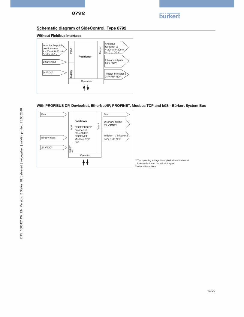
Schematic diagram of SideControl, Type 8792
Without Fieldbus interface
With PROFIBUS DP, DeviceNet, EtherNet/IP, PROFINET, Modbus TCP and büS - Bürkert System Bus
4) The operating voltage is supplied with a 3-wire unit
independent from the setpoint signal5) Alternative options
Binary input
24 V DC4)
Positioner
PROFIBUS DPDeviceNetEtherNet/IP PROFINET Modbus TCPbüS
2 Binary output
24 V PNP5)
Initiator 1 / Initiator 2
24 V PNP NO5)
Inp
ut
Ou
tpu
t
Su
pp
ly
un
it
Operation
BusBus
Input for Setpointposition value4 - 20mA, 0-20 mA0-10 V, 0-5 V
Binary input
Operation
Positioner
Inp
ut
Ou
tpu
t
Su
pp
ly
2 binary outputs24 V PNP5)
Analogue feedback 2) 4-20mA, 0-20mA, 0-10 V, 0-5 V
Initiator 1/Initiator 224 V PNP NO5)
24 V DC4)

8792
18/20
Dimensions [mm]
Description L A A1 A2
Standard 171.1 31 30 –
PROFIBUS DP 157.8 36 31 13.5
Multipole Bin. OUT 157.6 36 31 –
Mulitpole 157.4 - 22.5 –
Remote 171.1 31 30 11.5
NAMUR versionCable gland (standard)
7.5A
1
109.8
7.5
81.8A
17
NAMUR version PROFIBUS DP Multipole
A1
A2
A
A1
A
Remote version cable gland
A2
A1
A
NAMUR version Multipole
2550
1010
49.9
97.4
144.6
L
81
.99
8.9
A1
R A1 P A2
NAMUR version Multipole with Binary outputs
8792
19/20
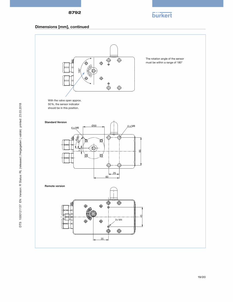
Dimensions [mm], continued
180°
With the valve open approx.
50 %, the sensor indicator
should be in this position.
The rotation angle of the sensor
must be within a range of 180°
35
45
2x M4
65
25
60
Ø50
7,5
45°4x
90°
4 x M64 x M8
Standard Version
Remote version

8792
20/20
Dimensions [mm], continued
ATEX / IECEx version
94
.6
11
1.8
5
To nd your nearest Bürkert facility, click on the orange box www.burkert.com
In case of special application conditions,
please consult for advice
Subject to alterations.
© Christian Bürkert GmbH & Co. KG 1803/16_EU-en_00895119