DIGITAL DIGITAL READOUTREADOUTREADOUT Operation Manual · PDF fileWheWhen using the manual: n...
121
SDS6 SDS6 SDS6 SDS6 DIGITAL DIGITAL DIGITAL DIGITAL READOUT READOUT READOUT READOUT Operation Manual Operation Manual Operation Manual Operation Manual
-
Upload
trannguyet -
Category
Documents
-
view
234 -
download
1
Transcript of DIGITAL DIGITAL READOUTREADOUTREADOUT Operation Manual · PDF fileWheWhen using the manual: n...
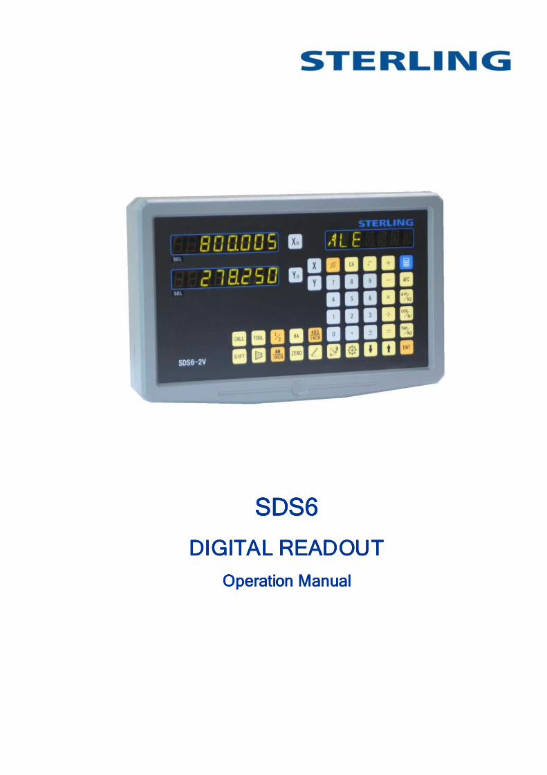
SDS6SDS6SDS6SDS6
DIGITAL DIGITAL DIGITAL DIGITAL READOUTREADOUTREADOUTREADOUT
Operation ManualOperation ManualOperation ManualOperation Manual
1
Dear User:Dear User:Dear User:Dear User: Thank you for purchasing digital readout from Sterling. You have made an excellent choice and we would like to draw your attention to a few points below to ensure you enjoy trouble free operation. Please read the following safety instructions and precautions for safe operation of your new digital readout.
WheWheWheWhen using the manual:n using the manual:n using the manual:n using the manual:
● Chapters and sections are listed in the table of contents ( see P5).
● This manual includes some instructions for panel keys of SDS6 digital
readout and other series, including.
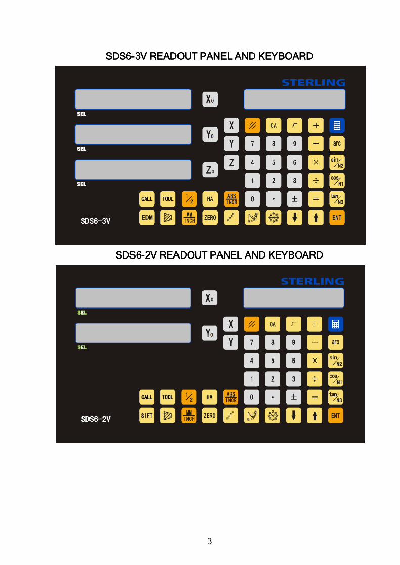
SDS6-2V the readout used for 2 axis milling machine and grinding machine and lathe machine
SDS6-3V the readout used for 3 axis milling machine and lathe machine and EDM machine
Safety Precautions:Safety Precautions:Safety Precautions:Safety Precautions:
Caution:Caution:Caution:Caution:
■ Do not splash coolant directly onto the unit to avoid risk of electric
shock or fire.
Warning:Warning:Warning:Warning:
■ Do not open the enclosure, there is no element repairable by the user
inside. Please return unit to your dealer / service department for repair.
■ If the unit is not used for a long time, the chargeable lithium batteries
for data retention may be damaged. Please contact agent or
professional technicians for battery replacement when required.
Notes:Notes:Notes:Notes:
● Disconnect power plug promptly if the digital display meter emits
smoke or peculiar smells, an electric shock or fire may be caused if
continuing to use it. Please contact you dealer and never attempt to
repair by yourself.
● The digital readout constitutes a precision detection device with an
optical electronic scale. Once the connecting wires between the two
parts are broken or damaged during use, error in signal data may
caused, to which the user should pay special attention.
2
● Do not repair or refit the digital display by yourself, damage might be
caused. In case of abnormality, please contact your dealer.
● If the optical scale used with the digital counter is damaged, do not
replace it with other brand of scale as different companies have their
respective characteristics and wiring. Never make wiring without the
guide of professional technicians or the digital counter / scale may be
damaged.
Notice: We reserve the right to make continual upgrades which may
change operation or specification slightly without prior notice.
The displacement sensor complies with 2006/95/EC directive for
low-voltage electric apparatus and 2004/108/EC directive for EMC.
Our manufacturing company has passed the authorization and the audit of
ISO9001 Quality System, ISO14001 Environmental System, OHSAS18001
Occupational Health and Safety System.
3
SDS6SDS6SDS6SDS6----3V READOUT PANEL AND KEYBOARD 3V READOUT PANEL AND KEYBOARD 3V READOUT PANEL AND KEYBOARD 3V READOUT PANEL AND KEYBOARD
SDS6SDS6SDS6SDS6----2V READOUT PANEL AND KEYBOARD2V READOUT PANEL AND KEYBOARD2V READOUT PANEL AND KEYBOARD2V READOUT PANEL AND KEYBOARD
4
﹟〞
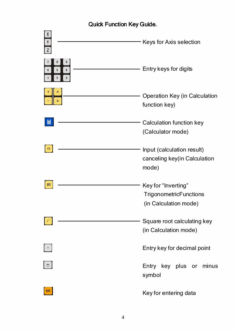
Quick Function Quick Function Quick Function Quick Function Key Key Key Key GuideGuideGuideGuide....
Keys for Axis selection
Entry keys for digits
Operation Key (in Calculation
function key)
Calculation function key
(Calculator mode)
Input (calculation result)
canceling key(in Calculation
mode)
Key for “Inverting”
TrigonometricFunctions
(in Calculation mode)
Square root calculating key
(in Calculation mode)
Entry key for decimal point
Entry key plus or minus
symbol
Key for entering data
5
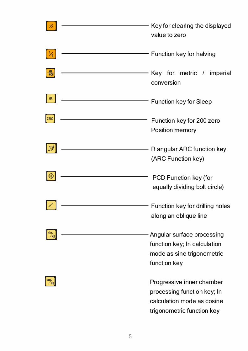
Key for clearing the displayed
value to zero
Function key for halving
Key for metric / imperial
conversion
Function key for Sleep
Function key for 200 zero
Position memory
R angular ARC function key
(ARC Function key)
PCD Function key (for
equally dividing bolt circle)
Function key for drilling holes
along an oblique line
Angular surface processing
function key; In calculation
mode as sine trigonometric
function key
Progressive inner chamber
processing function key; In
calculation mode as cosine
trigonometric function key
6
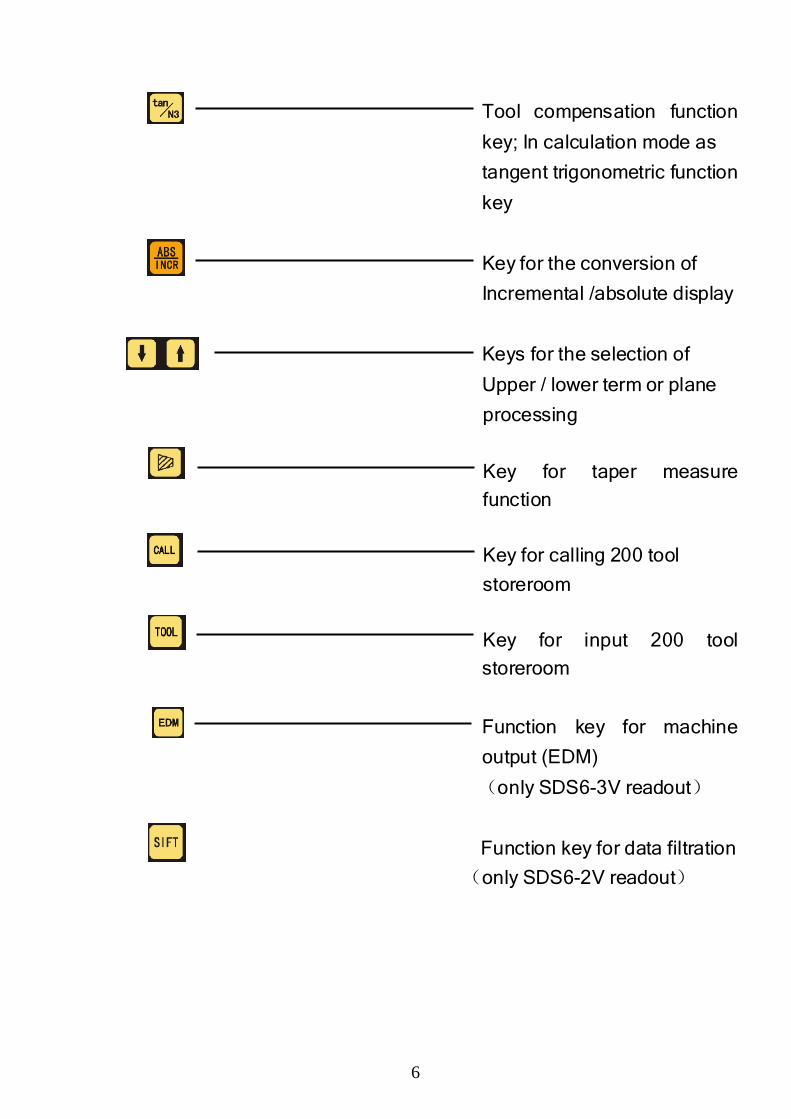
Tool compensation function
key; In calculation mode as
tangent trigonometric function
key
Key for the conversion of
Incremental /absolute display
Keys for the selection of
Upper / lower term or plane
processing
Key for taper measure
function
Key for calling 200 tool
storeroom
Key for input 200 tool
storeroom
Function key for machine
output (EDM)
(only SDS6-3V readout)
Function key for data filtration
(only SDS6-2V readout)
7
SEL
SEL
SEL
Model
Number of axes
Display resolut ion
Special mark for milling machine
I. I. I. I. SettingsSettingsSettingsSettings
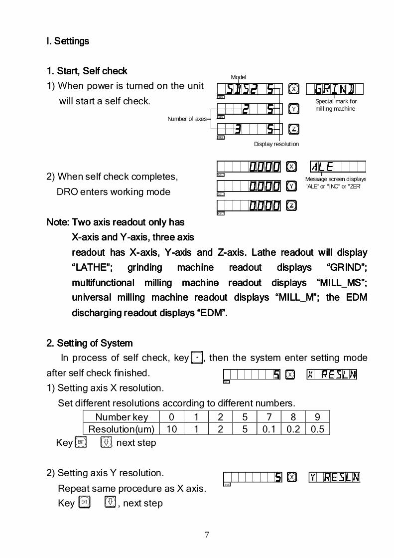
1. Start, Self check1. Start, Self check1. Start, Self check1. Start, Self check
1) When power is turned on the unit
will start a self check.
2) When self check completes,
DRO enters working mode
Note: Two axiNote: Two axiNote: Two axiNote: Two axissss readout only hasreadout only hasreadout only hasreadout only has
XXXX----axis and Yaxis and Yaxis and Yaxis and Y----axis, axis, axis, axis, three axisthree axisthree axisthree axis
readout has Xreadout has Xreadout has Xreadout has X----axis, axis, axis, axis, YYYY----axis and Zaxis and Zaxis and Zaxis and Z----axis. axis. axis. axis. LLLLathe readout athe readout athe readout athe readout will will will will display display display display
“LATHE”; grinding machine readout display“LATHE”; grinding machine readout display“LATHE”; grinding machine readout display“LATHE”; grinding machine readout displayssss “GRIND”; “GRIND”; “GRIND”; “GRIND”;
multifunctional milling machine readout displaymultifunctional milling machine readout displaymultifunctional milling machine readout displaymultifunctional milling machine readout displayssss “MILL_MS”; “MILL_MS”; “MILL_MS”; “MILL_MS”;
universal milling machine readout displayuniversal milling machine readout displayuniversal milling machine readout displayuniversal milling machine readout displayssss “MILL_M”; the “MILL_M”; the “MILL_M”; the “MILL_M”; the EDM EDM EDM EDM
discharging readout displaydischarging readout displaydischarging readout displaydischarging readout displayssss “EDM”.“EDM”.“EDM”.“EDM”.
2. Setting of System2. Setting of System2. Setting of System2. Setting of System
In process of self check, key , then the system enter setting mode
after self check finished.
1) Setting axis X resolution.
Set different resolutions according to different numbers.
Number key 0 1 2 5 7 8 9 Resolution(um) 10 1 2 5 0.1 0.2 0.5
Key , next step
2) Setting axis Y resolution.
Repeat same procedure as X axis.
Key , next step
SEL
SE L
SEL
SEL
SEL
Message screen displays "ALE" or "INC" or "ZER"
8
SEL
SEL
SEL
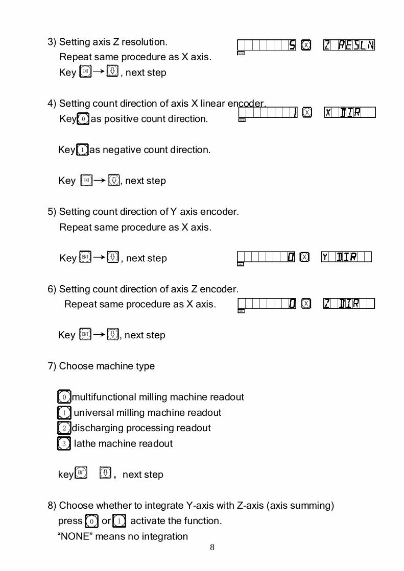
3) Setting axis Z resolution.
Repeat same procedure as X axis.
Key , next step
4) Setting count direction of axis X linear encoder.
Key as positive count direction.
Key as negative count direction.
Key , next step
5) Setting count direction of Y axis encoder.
Repeat same procedure as X axis.
Key , next step
6) Setting count direction of axis Z encoder.
Repeat same procedure as X axis.
Key , next step
7) Choose machine type
multifunctional milling machine readout
universal milling machine readout
discharging processing readout
lathe machine readout
key ,next step
8) Choose whether to integrate Y-axis with Z-axis (axis summing)
press or activate the function.
“NONE” means no integration
SEL
0
1
0
1
2
3
0 1
9
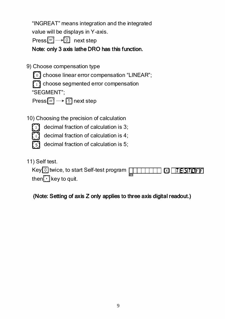
“INGREAT” means integration and the integrated
value will be displays in Y-axis.
Press ,next step
Note: only Note: only Note: only Note: only 3 axis3 axis3 axis3 axis lathe lathe lathe lathe DRO DRO DRO DRO has this function.has this function.has this function.has this function.
9) Choose compensation type
choose linear error compensation “LINEAR”;
choose segmented error compensation
“SEGMENT”;
Press next step
10) Choosing the precision of calculation
decimal fraction of calculation is 3;
decimal fraction of calculation is 4;
decimal fraction of calculation is 5;
11) Self test.
Key twice, to start Self-test program
then key to quit.
(Note: Setting of axis Z only applies to three axis digital readout.)(Note: Setting of axis Z only applies to three axis digital readout.)(Note: Setting of axis Z only applies to three axis digital readout.)(Note: Setting of axis Z only applies to three axis digital readout.)
ALE
0
3
4
5
1
10
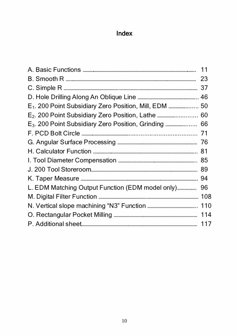
IndexIndexIndexIndex
A. Basic Functions …………………………………………………………………………………. 11
B. Smooth R ……………………………………………………………………………………………… 23 C. Simple R ……………………………………….…………….………………………………………… 37
D. Hole Drilling Along An Oblique Line ………………………………………….. 46 E1. 200 Point Subsidiary Zero Position, Mill, EDM ……………....... 50
E2. 200 Point Subsidiary Zero Position, Lathe ……………............. 60 E3. 200 Point Subsidiary Zero Position, Grinding ……………........ 66
F. PCD Bolt Circle …………………………………....................................... 71 G. Angular Surface Processing ………………………………………………………… 76
H. Calculator Function ………………………………………………………………………….. 81 I. Tool Diameter Compensation ……………………………………………………….. 85
J. 200 Tool Storeroom……………………………………………………………………………. 89 K. Taper Measure ……………………………………………………………………………………. 94
L. EDM Matching Output Function (EDM model only)……………. 96 M. Digital Filter Function ………………………………….…………………………………… 108
N. Vertical slope machining “N3” Function ………………………………….. 110 O. Rectangular Pocket Milling …………………………………………………………… 114
P. Additional sheet…………………………………………………………………………………… 117
11
A.A.A.A.
Basic FunctionsBasic FunctionsBasic FunctionsBasic Functions
12
2013
5
A B C
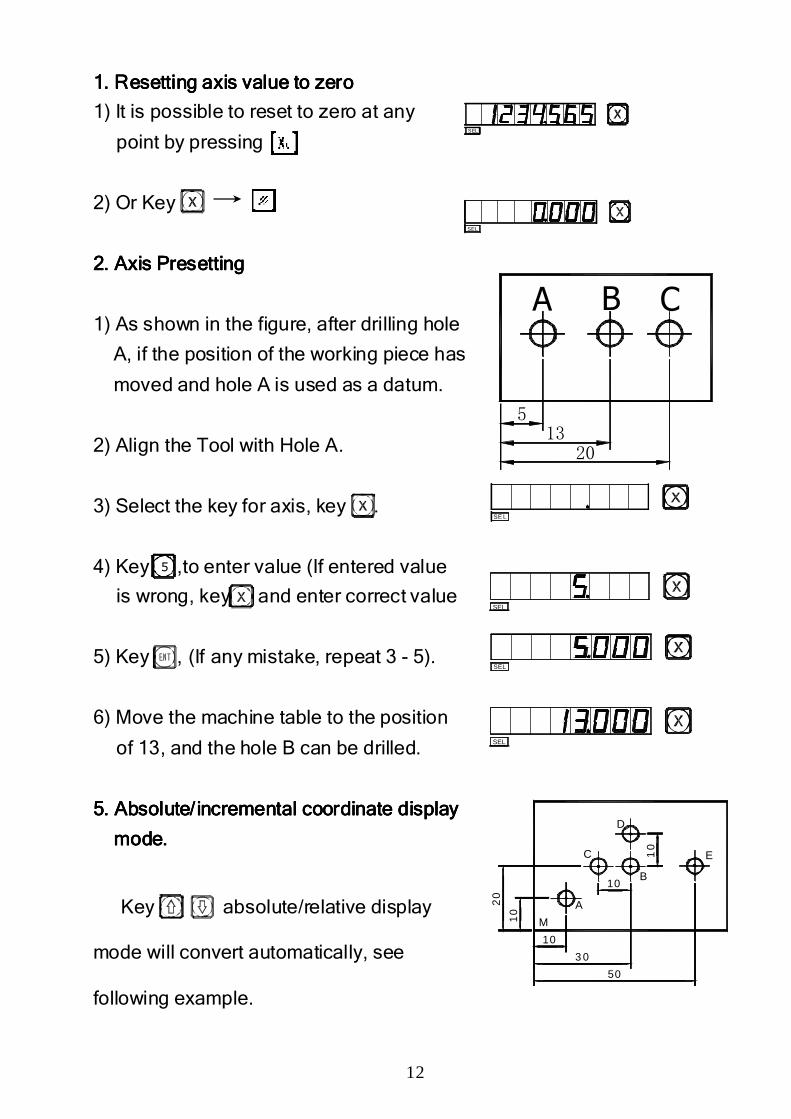
1111. . . . Resetting axis value to zeroResetting axis value to zeroResetting axis value to zeroResetting axis value to zero
1) It is possible to reset to zero at any
point by pressing
2) Or Key
2. Axis Presetting2. Axis Presetting2. Axis Presetting2. Axis Presetting
1) As shown in the figure, after drilling hole
A, if the position of the working piece has
moved and hole A is used as a datum.
2) Align the Tool with Hole A.
3) Select the key for axis, key .
4) Key ,to enter value (If entered value
is wrong, key and enter correct value
5) Key , (If any mistake, repeat 3 - 5).
6) Move the machine table to the position
of 13, and the hole B can be drilled.
5. Absolute/5. Absolute/5. Absolute/5. Absolute/ incrementalincrementalincrementalincremental coordinate display coordinate display coordinate display coordinate display
mode.mode.mode.mode.
Key absolute/relative display
mode will convert automatically, see
following example.
SEL
SEL
5
SE L
SEL
SEL
SEL
M
A
D
C
B
E
50
3 0
10
10
10
20
10
13
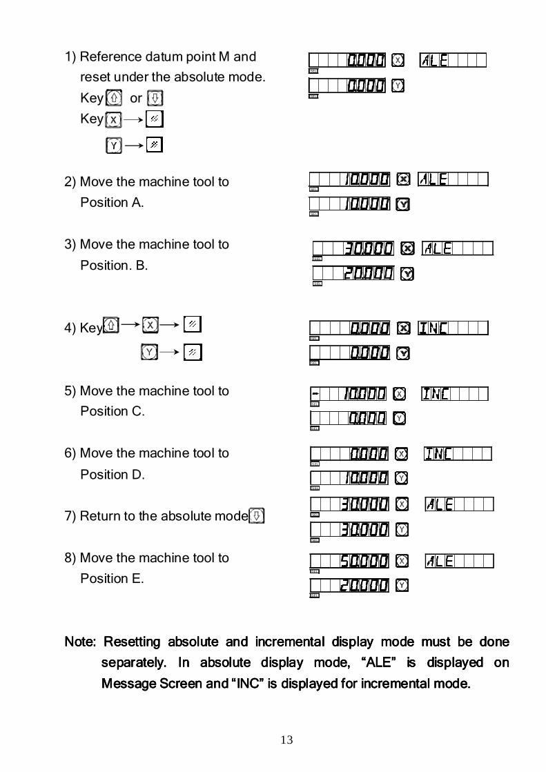
1) Reference datum point M and
reset under the absolute mode.
Key or
Key
2) Move the machine tool to
Position A.
3) Move the machine tool to
Position. B.
4) Key
5) Move the machine tool to
Position C.
6) Move the machine tool to
Position D.
7) Return to the absolute mode
8) Move the machine tool to
Position E.
Note: Note: Note: Note: RRRResetting absolute and esetting absolute and esetting absolute and esetting absolute and incremental incremental incremental incremental display mode must be done display mode must be done display mode must be done display mode must be done
separately. In absolute display mode, “ALE” is displayed on separately. In absolute display mode, “ALE” is displayed on separately. In absolute display mode, “ALE” is displayed on separately. In absolute display mode, “ALE” is displayed on
Message ScreenMessage ScreenMessage ScreenMessage Screen and and and and “INC” is “INC” is “INC” is “INC” is displayed for incremental modedisplayed for incremental modedisplayed for incremental modedisplayed for incremental mode....
SEL
SEL
SEL
SEL
S EL
S EL
SEL
SEL
SEL
SEL
SEL
SEL
SEL
SEL
SEL
SEL
14
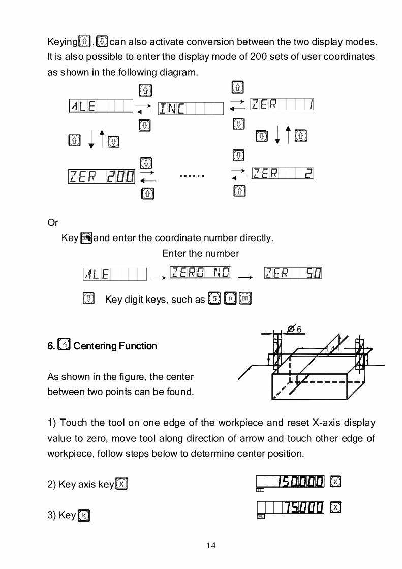
Keying , can also activate conversion between the two display modes.
It is also possible to enter the display mode of 200 sets of user coordinates
as shown in the following diagram.
Or
Key and enter the coordinate number directly.
Enter the number
Key digit keys, such as
6.6.6.6. Centering FunctionCentering FunctionCentering FunctionCentering Function
As shown in the figure, the center
between two points can be found.
1) Touch the tool on one edge of the workpiece and reset X-axis display
value to zero, move tool along direction of arrow and touch other edge of
workpiece, follow steps below to determine center position.
2) Key axis key
3) Key
5 0
12
12
S EL
SEL
144
6
15
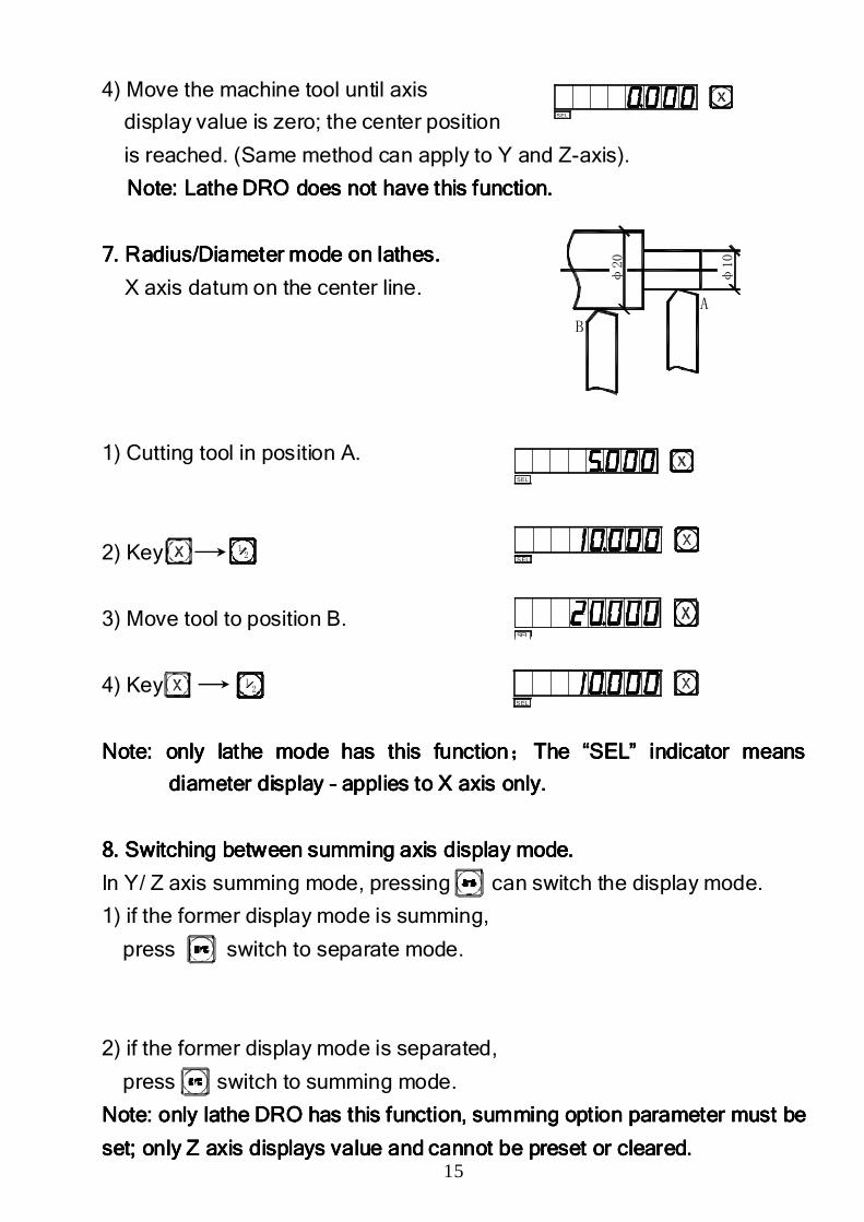
4) Move the machine tool until axis
display value is zero; the center position
is reached. (Same method can apply to Y and Z-axis).
NNNNote: Lathe ote: Lathe ote: Lathe ote: Lathe DRO does not have DRO does not have DRO does not have DRO does not have this function.this function.this function.this function.
7. Radius/Diameter 7. Radius/Diameter 7. Radius/Diameter 7. Radius/Diameter mode on lathesmode on lathesmode on lathesmode on lathes....
X axis datum on the center line.
1) Cutting tool in position A.
2) Key
3) Move tool to position B.
4) Key
NoteNoteNoteNote: only lathe : only lathe : only lathe : only lathe mode mode mode mode has this functionhas this functionhas this functionhas this function;;;;The The The The “SEL” indicator means “SEL” indicator means “SEL” indicator means “SEL” indicator means
diameter displaydiameter displaydiameter displaydiameter display –––– applies to X axis onlyapplies to X axis onlyapplies to X axis onlyapplies to X axis only....
8888. . . . SSSSwitchwitchwitchwitching betweening betweening betweening between summing axis summing axis summing axis summing axis displaydisplaydisplaydisplay modemodemodemode....
In Y/ Z axis summing mode, pressing can switch the display mode.
1) if the former display mode is summing,
press switch to separate mode.
2) if the former display mode is separated,
press switch to summing mode.
Note: only lathe Note: only lathe Note: only lathe Note: only lathe DRO DRO DRO DRO has thhas thhas thhas thisisisis functionfunctionfunctionfunction,,,, summing option summing option summing option summing option parameter must be parameter must be parameter must be parameter must be
set; only set; only set; only set; only Z axis Z axis Z axis Z axis displays displays displays displays value and cannotvalue and cannotvalue and cannotvalue and cannot be preset or clearbe preset or clearbe preset or clearbe preset or clearedededed. . . .
SEL
SEL
SEL
SEL
SEL
B
A
φ20
φ10
12
12
16
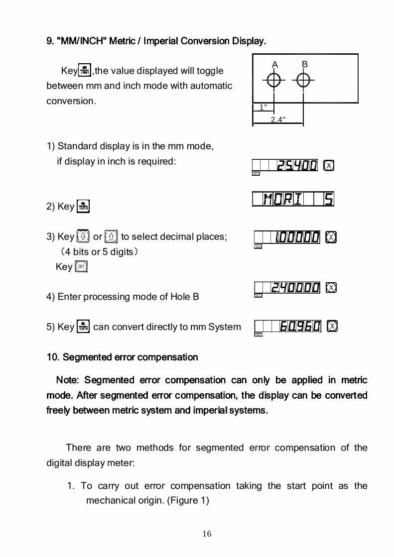
9. "MM/INCH" 9. "MM/INCH" 9. "MM/INCH" 9. "MM/INCH" Metric / ImperialMetric / ImperialMetric / ImperialMetric / Imperial Conversion Display.Conversion Display.Conversion Display.Conversion Display.
Key ,the value displayed will toggle
between mm and inch mode with automatic
conversion.
1) Standard display is in the mm mode,
if display in inch is required:
2) Key
3) Key or to select decimal places;
(4 bits or 5 digits)
Key
4) Enter processing mode of Hole B
5) Key can convert directly to mm System
10. Segmented error compensation 10. Segmented error compensation 10. Segmented error compensation 10. Segmented error compensation
Note: Note: Note: Note: Segmented error compensation Segmented error compensation Segmented error compensation Segmented error compensation can can can can only only only only be applied be applied be applied be applied in in in in metric metric metric metric
modemodemodemode. . . . After sAfter sAfter sAfter segmented error compensation, the displayegmented error compensation, the displayegmented error compensation, the displayegmented error compensation, the display can be converted can be converted can be converted can be converted
freely betweenfreely betweenfreely betweenfreely between metric system and imetric system and imetric system and imetric system and imperial systemmperial systemmperial systemmperial systemssss....
There are two methods for segmented error compensation of the
digital display meter:
1. To carry out error compensation taking the start point as the
mechanical origin. (Figure 1)
SEL
SEL
SEL
SEL
A B
2.4"
1"
17
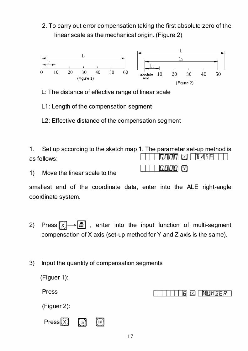
2. To carry out error compensation taking the first absolute zero of the
linear scale as the mechanical origin. (Figure 2)
L: The distance of effective range of linear scale
L1: Length of the compensation segment
L2: Effective distance of the compensation segment
1. Set up according to the sketch map 1. The parameter set-up method is
as follows:
1) Move the linear scale to the
smallest end of the coordinate data, enter into the ALE right-angle
coordinate system.
2) Press , enter into the input function of multi-segment
compensation of X axis (set-up method for Y and Z axis is the same).
3) Input the quantity of compensation segments
(Figuer 1):
Press
(Figuer 2):
Press 5
18
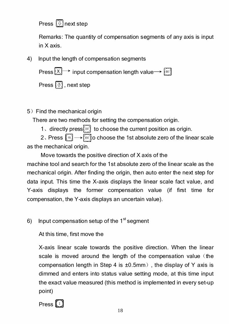
Press , next step
Remarks: The quantity of compensation segments of any axis is input
in X axis.
4) Input the length of compensation segments
Press input compensation length value
Press , next step
5)Find the mechanical origin
There are two methods for setting the compensation origin.
1、directly press to choose the current position as origin.
2、Press to choose the 1st absolute zero of the linear scale
as the mechanical origin.
Move towards the positive direction of X axis of the
machine tool and search for the 1st absolute zero of the linear scale as the
mechanical origin. After finding the origin, then auto enter the next step for
data input. This time the X-axis displays the linear scale fact value, and
Y-axis displays the former compensation value (if first time for
compensation, the Y-axis displays an uncertain value).
6) Input compensation setup of the 1st segment
At this time, first move the
X-axis linear scale towards the positive direction. When the linear
scale is moved around the length of the compensation value(the
compensation length in Step 4 is ±0.5mm), the display of Y axis is
dimmed and enters into status value setting mode, at this time input
the exact value measured (this method is implemented in every set-up
point)
Press 1
19
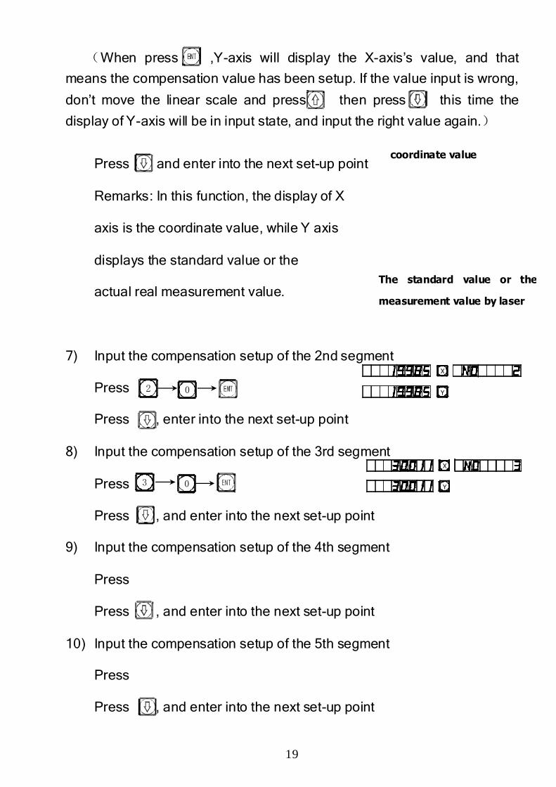
(When press ,Y-axis will display the X-axis’s value, and that
means the compensation value has been setup. If the value input is wrong,
don’t move the linear scale and press then press this time the
display of Y-axis will be in input state, and input the right value again.)
Press , and enter into the next set-up point
Remarks: In this function, the display of X
axis is the coordinate value, while Y axis
displays the standard value or the
actual real measurement value.
7) Input the compensation setup of the 2nd segment
Press
Press , enter into the next set-up point
8) Input the compensation setup of the 3rd segment
Press
Press , and enter into the next set-up point
9) Input the compensation setup of the 4th segment
Press
Press , and enter into the next set-up point
10) Input the compensation setup of the 5th segment
Press
Press , and enter into the next set-up point
02
3 0
coordinate value
The standard value or the
measurement value by laser
Y
X
Y
X
20
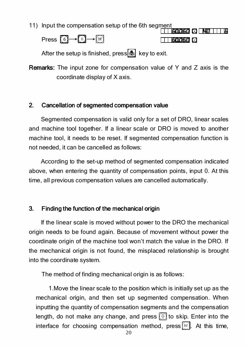
11) Input the compensation setup of the 6th segment
Press
After the setup is finished, press key to exit.
Remarks: Remarks: Remarks: Remarks: The input zone for compensation value of Y and Z axis is the
coordinate display of X axis.
2.2.2.2. Cancellation of sCancellation of sCancellation of sCancellation of segmented compensation valueegmented compensation valueegmented compensation valueegmented compensation value
Segmented compensation is valid only for a set of DRO, linear scales
and machine tool together. If a linear scale or DRO is moved to another
machine tool, it needs to be reset. If segmented compensation function is
not needed, it can be cancelled as follows:
According to the set-up method of segmented compensation indicated
above, when entering the quantity of compensation points, input 0. At this
time, all previous compensation values are cancelled automatically.
3.3.3.3. Finding the function of the mechaFinding the function of the mechaFinding the function of the mechaFinding the function of the mechanical originnical originnical originnical origin
If the linear scale is moved without power to the DRO the mechanical
origin needs to be found again. Because of movement without power the
coordinate origin of the machine tool won’t match the value in the DRO. If
the mechanical origin is not found, the misplaced relationship is brought
into the coordinate system.
The method of finding mechanical origin is as follows:
1.Move the linear scale to the position which is initially set up as the
mechanical origin, and then set up segmented compensation. When
inputting the quantity of compensation segments and the compensation
length, do not make any change, and press to skip. Enter into the
interface for choosing compensation method, press . At this time,
6 0 Y
X
21
directly press to quit compensation setup and finish finding the
mechanical origin.
2. First move the linear scale to the smallest value, and then set up
segmented compensation. When inputting the quantity of compensation
segments and the compensation length, do not make any change, and
press .directly to skip. Enter into the interface for choosing
compensation method, press to enter X axis to find the status
of absolute zero. Move the linear scale towards the positive direction.
When the absolute zero is found, it is the mechanical origin. The DRO
processes automatically. At this time, press key to quit the
compensation setup and finish finding the mechanical origin. (Remarks:
It is applicable to setting up parameters according to sketch map 2)
Note: Note: Note: Note: AfterAfterAfterAfter findfindfindfindinginginging thethethethe mechanicalmechanicalmechanicalmechanical origin, the userorigin, the userorigin, the userorigin, the user----coordinate will coordinate will coordinate will coordinate will
resume.resume.resume.resume.
Advise: find the mechanical origin before startAdvise: find the mechanical origin before startAdvise: find the mechanical origin before startAdvise: find the mechanical origin before startinginginging to to to to work after power work after power work after power work after power
on to on to on to on to ensureensureensureensure coordinate origin of the machine tool matchcoordinate origin of the machine tool matchcoordinate origin of the machine tool matchcoordinate origin of the machine tool matcheseseses the the the the value in value in value in value in
the DROthe DROthe DROthe DRO....
11. Linear Error Compensation11. Linear Error Compensation11. Linear Error Compensation11. Linear Error Compensation
Linear error compensation function is used to make linear correction
of errors.
Correction factor S =(L-L')/(L/1000) mm/m
L---the actual measured length (mm)
L'---the displayed value on DRO (mm)
S---the actual factor (mm/m), "+" means actual length is larger, and "-"
means actual length is smaller.
Compensation range: -1.500 mm/m~+1.500 mm/m
Example: The actual measured length of the machine table is 1000
mm, and the display value on the DRO is 999.98 mm.
22
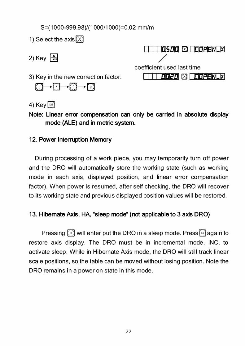
S=(1000-999.98)/(1000/1000)=0.02 mm/m
1) Select the axis
2) Key
coefficient used last time
3) Key in the new correction factor:
4) Key
Note: LNote: LNote: LNote: Linear error compensation can only be carried in absolute display inear error compensation can only be carried in absolute display inear error compensation can only be carried in absolute display inear error compensation can only be carried in absolute display mode (ALE) and mode (ALE) and mode (ALE) and mode (ALE) and in in in in metric systemmetric systemmetric systemmetric system....
12. Power Interruption Memory12. Power Interruption Memory12. Power Interruption Memory12. Power Interruption Memory
During processing of a work piece, you may temporarily turn off power
and the DRO will automatically store the working state (such as working
mode in each axis, displayed position, and linear error compensation
factor). When power is resumed, after self checking, the DRO will recover
to its working state and previous displayed position values will be restored.
13. 13. 13. 13. Hibernate Axis, HA, “sHibernate Axis, HA, “sHibernate Axis, HA, “sHibernate Axis, HA, “sleep leep leep leep mode”mode”mode”mode” (no(no(no(notttt applicable to 3 axis DROapplicable to 3 axis DROapplicable to 3 axis DROapplicable to 3 axis DRO))))
Pressing will enter put the DRO in a sleep mode. Press again to
restore axis display. The DRO must be in incremental mode, INC, to
activate sleep. While in Hibernate Axis mode, the DRO will still track linear
scale positions, so the table can be moved without losing position. Note the
DRO remains in a power on state in this mode.
0 0 2
23
B.B.B.B.
Smooth RSmooth RSmooth RSmooth R FunctionFunctionFunctionFunction
24
Smooth R Arc Calculation function (ARC Function)Smooth R Arc Calculation function (ARC Function)Smooth R Arc Calculation function (ARC Function)Smooth R Arc Calculation function (ARC Function)
The advanced smooth R arc calculation function makes it possible to
machine a radius quickly and easily with a universal milling machine. The
function makes it possible to control smoothness of the arc by setting the
distance between two adjoining working points.
① The message window display prompts the operator to enter all the
parameters, so it is very easy to operate.
②The arc can based on the input maximum cut (MAX CUT) and
calculates the proper depth of cut / step, so arc smoothness is under
operator’s control.
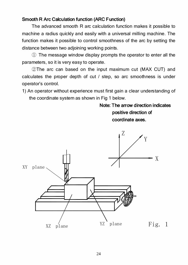
1) An operator without experience must first gain a clear understanding of
the coordinate system as shown in Fig 1 below.
Note: The arrow direction iNote: The arrow direction iNote: The arrow direction iNote: The arrow direction indicatesndicatesndicatesndicates
positive direction of positive direction of positive direction of positive direction of
coordinate axes.coordinate axes.coordinate axes.coordinate axes.
YZ planeXZ plane
XY plane
Fig. 1
ZY
X
25
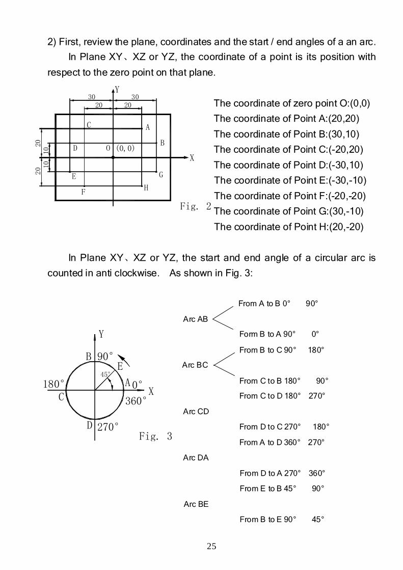
2) First, review the plane, coordinates and the start / end angles of a an arc.
In Plane XY、XZ or YZ, the coordinate of a point is its position with
respect to the zero point on that plane.
The coordinate of zero point O:(0,0)
The coordinate of Point A:(20,20)
The coordinate of Point B:(30,10)
The coordinate of Point C:(-20,20)
The coordinate of Point D:(-30,10)
The coordinate of Point E:(-30,-10)
The coordinate of Point F:(-20,-20)
The coordinate of Point G:(30,-10)
The coordinate of Point H:(20,-20)
In Plane XY、XZ or YZ, the start and end angle of a circular arc is
counted in anti clockwise. As shown in Fig. 3:
From A to B 0° 90°
Arc AB
Form B to A 90° 0°
From B to C 90° 180°
Arc BC
From C to B 180° 90°
From C to D 180° 270°
Arc CD
From D to C 270° 180°
From A to D 360° 270°
Arc DA
From D to A 270° 360°
From E to B 45° 90°
Arc BE
From B to E 90° 45°
X
45°
Fig. 3
C
D 270°
360°
180°
BE
90°
0°A
Y
2020 10
3020
(0,0)
F
E
C
D O
H
G
Fig. 2
X
A
B
Y
2030
10
26
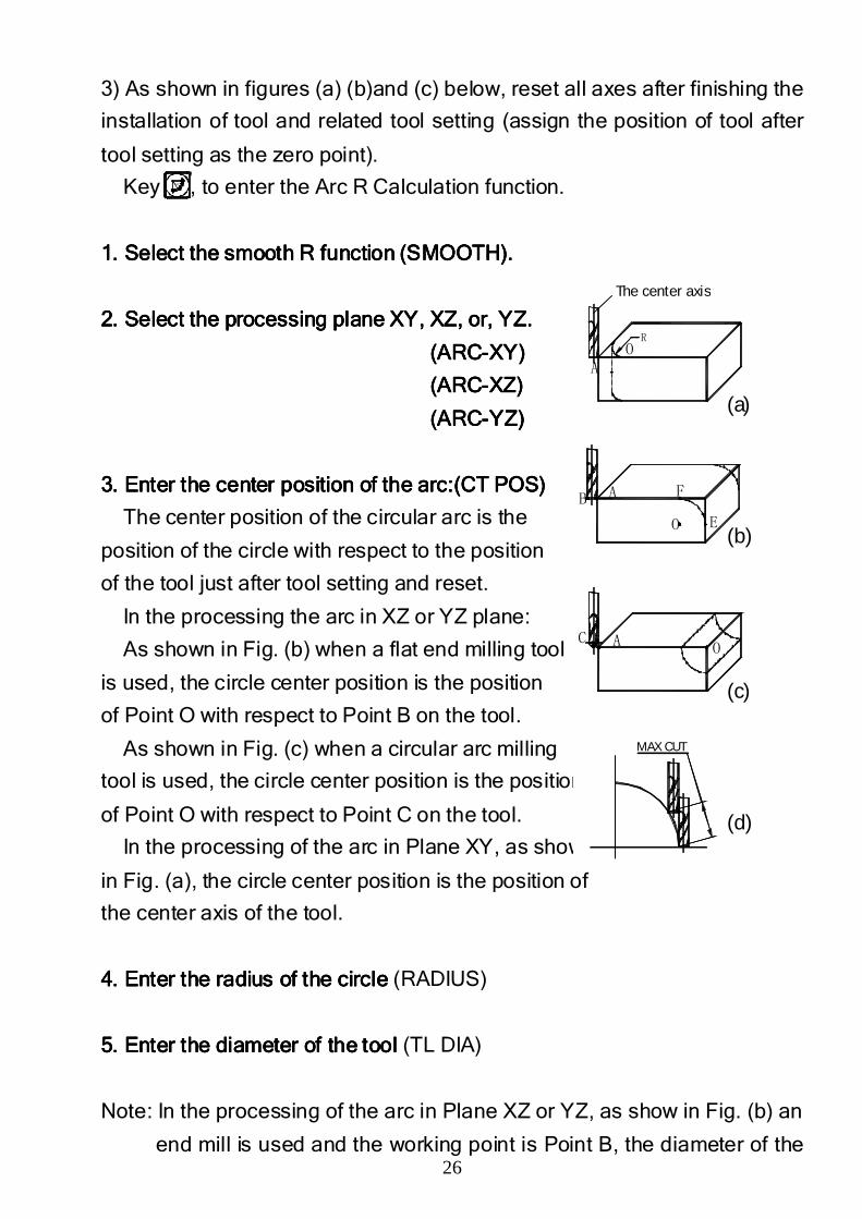
3) As shown in figures (a) (b)and (c) below, reset all axes after finishing the
installation of tool and related tool setting (assign the position of tool after
tool setting as the zero point).
Key , to enter the Arc R Calculation function.
1. Select the smooth R function (SMOOTH).1. Select the smooth R function (SMOOTH).1. Select the smooth R function (SMOOTH).1. Select the smooth R function (SMOOTH).
2. Select 2. Select 2. Select 2. Select the processing plane XYthe processing plane XYthe processing plane XYthe processing plane XY, , , , XZXZXZXZ,,,, orororor,,,, YZ.YZ.YZ.YZ.
(ARC(ARC(ARC(ARC----XY)XY)XY)XY)
(ARC(ARC(ARC(ARC----XZ)XZ)XZ)XZ)
(ARC(ARC(ARC(ARC----YZ)YZ)YZ)YZ)
3. Enter the center position of the arc:(CT POS)3. Enter the center position of the arc:(CT POS)3. Enter the center position of the arc:(CT POS)3. Enter the center position of the arc:(CT POS)
The center position of the circular arc is the
position of the circle with respect to the position
of the tool just after tool setting and reset.
In the processing the arc in XZ or YZ plane:
As shown in Fig. (b) when a flat end milling tool
is used, the circle center position is the position
of Point O with respect to Point B on the tool.
As shown in Fig. (c) when a circular arc milling
tool is used, the circle center position is the position
of Point O with respect to Point C on the tool.
In the processing of the arc in Plane XY, as shown
in Fig. (a), the circle center position is the position of
the center axis of the tool.
4. Enter the radius of the circle 4. Enter the radius of the circle 4. Enter the radius of the circle 4. Enter the radius of the circle (RADIUS)
5. Enter the diameter of the tool 5. Enter the diameter of the tool 5. Enter the diameter of the tool 5. Enter the diameter of the tool (TL DIA)
Note: In the processing of the arc in Plane XZ or YZ, as show in Fig. (b) an
end mill is used and the working point is Point B, the diameter of the
R
C A
B A
AO
O
O
F
E
MAX CUT
R
(a)
(b)
(c)
(d)
The center axis
27
tool does not factor in the processing, enter (TL DIA) =0.
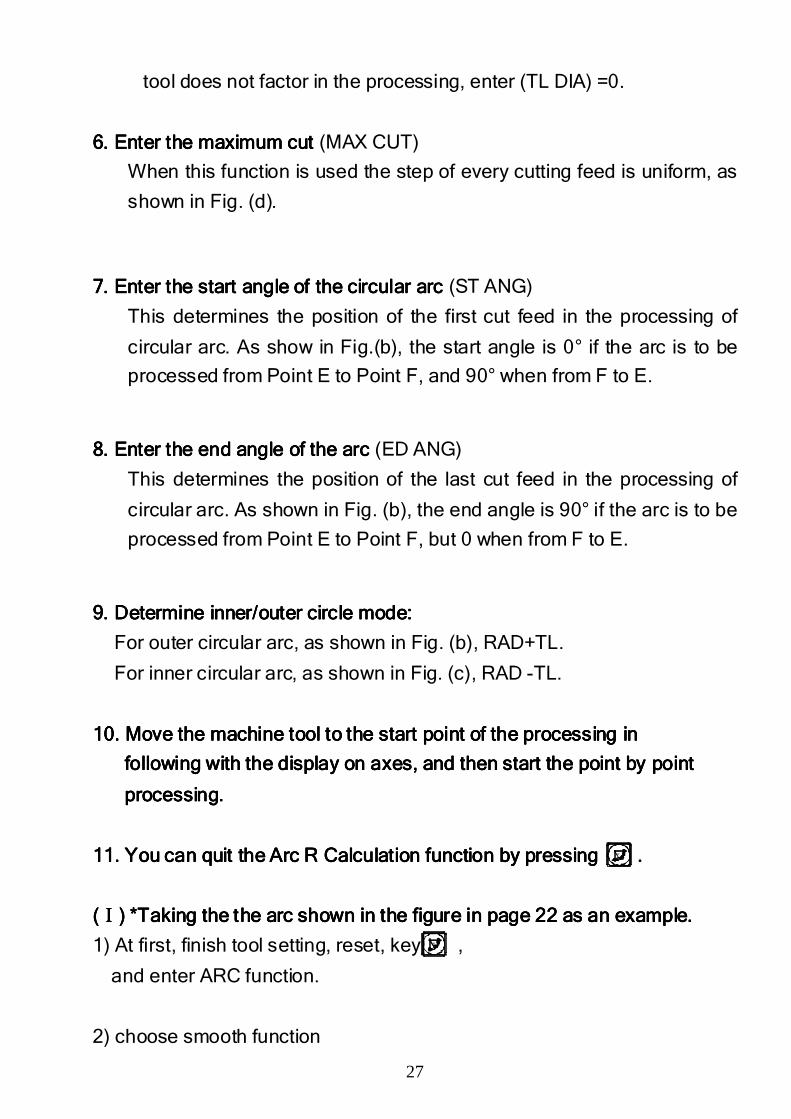
6. Enter the maximum6. Enter the maximum6. Enter the maximum6. Enter the maximum cut cut cut cut (MAX CUT)
When this function is used the step of every cutting feed is uniform, as
shown in Fig. (d).
7. Enter the start angle of the circular arc 7. Enter the start angle of the circular arc 7. Enter the start angle of the circular arc 7. Enter the start angle of the circular arc (ST ANG)
This determines the position of the first cut feed in the processing of
circular arc. As show in Fig.(b), the start angle is 0° if the arc is to be
processed from Point E to Point F, and 90° when from F to E.
8. Enter the end angle of the arc 8. Enter the end angle of the arc 8. Enter the end angle of the arc 8. Enter the end angle of the arc (ED ANG)
This determines the position of the last cut feed in the processing of
circular arc. As shown in Fig. (b), the end angle is 90° if the arc is to be
processed from Point E to Point F, but 0 when from F to E.
9. Determine inner/outer circle mode:9. Determine inner/outer circle mode:9. Determine inner/outer circle mode:9. Determine inner/outer circle mode:
For outer circular arc, as shown in Fig. (b), RAD+TL.
For inner circular arc, as shown in Fig. (c), RAD -TL.
10. Move the machine tool to the start point of the processing in 10. Move the machine tool to the start point of the processing in 10. Move the machine tool to the start point of the processing in 10. Move the machine tool to the start point of the processing in
following with the display on axes, and then start the point by point following with the display on axes, and then start the point by point following with the display on axes, and then start the point by point following with the display on axes, and then start the point by point
processing.processing.processing.processing.
11. You can quit the Arc R Calculation function 11. You can quit the Arc R Calculation function 11. You can quit the Arc R Calculation function 11. You can quit the Arc R Calculation function by pressingby pressingby pressingby pressing ....
((((ⅠⅠⅠⅠ) *Taking) *Taking) *Taking) *Taking the the arc shown in the figure in page 22 as an example.the the arc shown in the figure in page 22 as an example.the the arc shown in the figure in page 22 as an example.the the arc shown in the figure in page 22 as an example.
1) At first, finish tool setting, reset, key ,
and enter ARC function.
2) choose smooth function
R
R
28
20 40
R20
(a) (b)
φ5
φ5
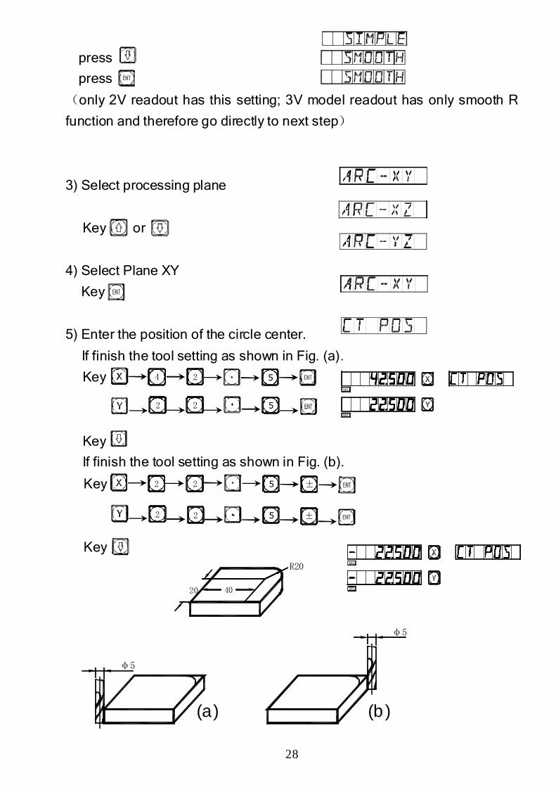
press
press
(only 2V readout has this setting; 3V model readout has only smooth R
function and therefore go directly to next step)
3) Select processing plane
Key or
4) Select Plane XY
Key
5) Enter the position of the circle center.
If finish the tool setting as shown in Fig. (a).
Key
Key
If finish the tool setting as shown in Fig. (b).
Key
Key
24 5
22 5
22
22
5
5 ±
±
SEL
SEL
SEL
SEL
29
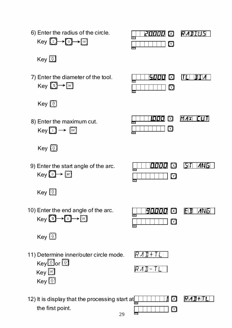
6) Enter the radius of the circle.
Key
Key
7) Enter the diameter of the tool.
Key
Key
8) Enter the maximum cut.
Key
Key
9) Enter the start angle of the arc.
Key
Key
10) Enter the end angle of the arc.
Key
Key
11) Determine inner/outer circle mode.
Key or
Key
Key
12) It is display that the processing start at
the first point.
2 0
5
1
0
09
SEL
SEL
SEL
SEL
S EL
S EL
SEL
SEL
SEL
SEL
SEL
SEL
30
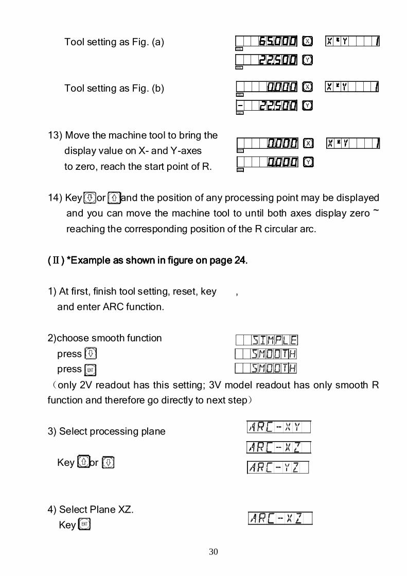
Tool setting as Fig. (a)
Tool setting as Fig. (b)
13) Move the machine tool to bring the
display value on X- and Y-axes
to zero, reach the start point of R.
14) Key or and the position of any processing point may be displayed
and you can move the machine tool to until both axes display zero ~
reaching the corresponding position of the R circular arc.
((((ⅡⅡⅡⅡ) *) *) *) *Example asExample asExample asExample as shown in figure shown in figure shown in figure shown in figure on on on on page 24page 24page 24page 24....
1) At first, finish tool setting, reset, key ,
and enter ARC function.
2)choose smooth function
press
press
(only 2V readout has this setting; 3V model readout has only smooth R
function and therefore go directly to next step)
3) Select processing plane
Key or
4) Select Plane XZ.
Key
SEL
SEL
SEL
SEL
SEL
SEL
31
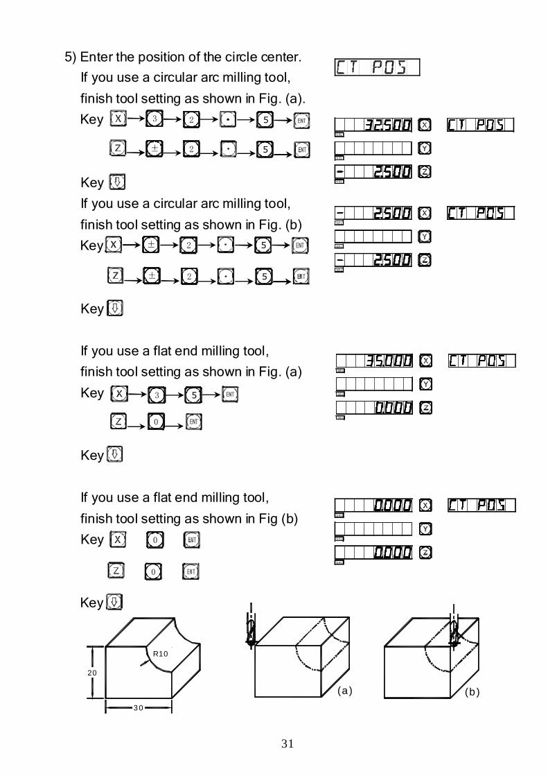
(a) (b)3 0
20
R10
5) Enter the position of the circle center.
If you use a circular arc milling tool,
finish tool setting as shown in Fig. (a).
Key
Key
If you use a circular arc milling tool,
finish tool setting as shown in Fig. (b)
Key
Key
If you use a flat end milling tool,
finish tool setting as shown in Fig. (a)
Key
Key
If you use a flat end milling tool,
finish tool setting as shown in Fig (b)
Key
Key
2 5
52±
3
±
±
2
2
5
5
3 5
0
0
0
S EL
S EL
S EL
SEL
SEL
SEL
SEL
SEL
SEL
S EL
S EL
S EL
32
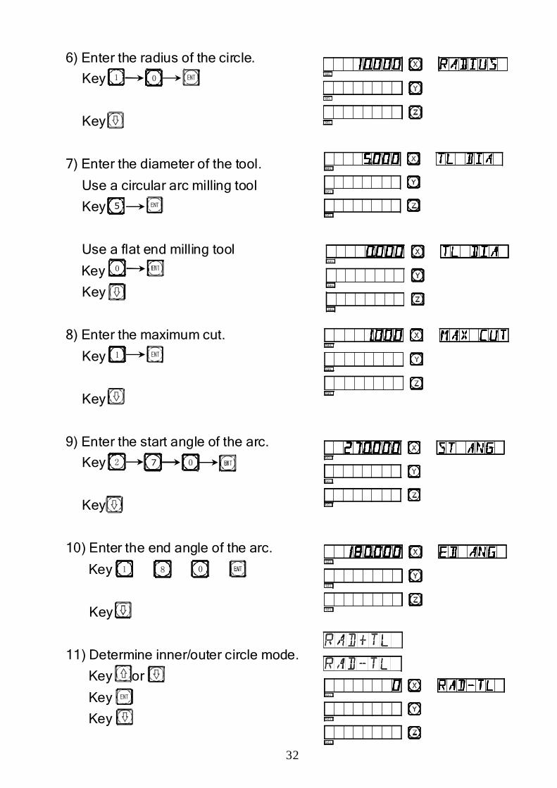
6) Enter the radius of the circle.
Key
Key
7) Enter the diameter of the tool.
Use a circular arc milling tool
Key
Use a flat end milling tool
Key
Key
8) Enter the maximum cut.
Key
Key
9) Enter the start angle of the arc.
Key
Key
10) Enter the end angle of the arc.
Key
Key
11) Determine inner/outer circle mode.
Key or
Key
Key
1 0
5
0
1
2 7 0
1 08
SEL
SEL
SEL
SEL
SEL
SEL
SEL
SEL
SEL
SEL
SEL
SEL
SEL
SEL
SEL
SEL
SEL
SEL
SEL
SEL
SEL
33
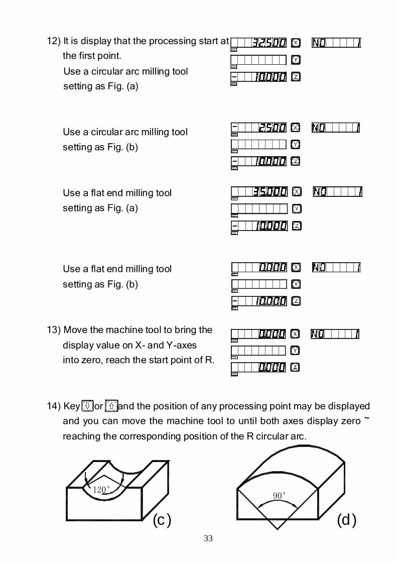
120°90°
(c ) (d)
12) It is display that the processing start at
the first point.
Use a circular arc milling tool
setting as Fig. (a)
Use a circular arc milling tool
setting as Fig. (b)
Use a flat end milling tool
setting as Fig. (a)
Use a flat end milling tool
setting as Fig. (b)
13) Move the machine tool to bring the
display value on X- and Y-axes
into zero, reach the start point of R.
14) Key or and the position of any processing point may be displayed
and you can move the machine tool to until both axes display zero ~
reaching the corresponding position of the R circular arc.
SEL
SEL
SEL
SEL
SEL
SEL
SEL
SEL
SEL
SEL
SEL
SEL
SEL
SEL
SEL
34
Note: When the arc to be processed in Planes XZ and YZ covers the
90° or the 270° position, for example, the one from 210° to 330°
covers 270° in Fig.(c), and the other from 135° to 45° covers 90° in
Fig. (d),end mill shall not be used.
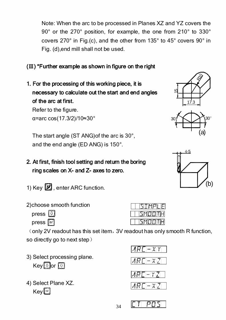
((((ⅢⅢⅢⅢ) *) *) *) *Further example as Further example as Further example as Further example as shown in shown in shown in shown in figure on the rightfigure on the rightfigure on the rightfigure on the right
1. For the processing of this working piece, it is1. For the processing of this working piece, it is1. For the processing of this working piece, it is1. For the processing of this working piece, it is
necessary to calculate out the start and end anglesnecessary to calculate out the start and end anglesnecessary to calculate out the start and end anglesnecessary to calculate out the start and end angles
of the arc at first.of the arc at first.of the arc at first.of the arc at first.
Refer to the figure.
α=arc cos(17.3/2)/10≈30°
The start angle (ST ANG)of the arc is 30°,
and the end angle (ED ANG) is 150°.
2. At first, finish tool setting and return the boring2. At first, finish tool setting and return the boring2. At first, finish tool setting and return the boring2. At first, finish tool setting and return the boring
ring scales on Xring scales on Xring scales on Xring scales on X---- and Zand Zand Zand Z---- axes to zero.axes to zero.axes to zero.axes to zero.
1) Key , enter ARC function.
2)choose smooth function
press
press
(only 2V readout has this set item,3V readout has only smooth R function,
so directly go to next step)
3) Select processing plane.
Key or
4) Select Plane XZ.
Key
R
30°
15
17.3
R10
30°
(a)
φ5
(b)
35
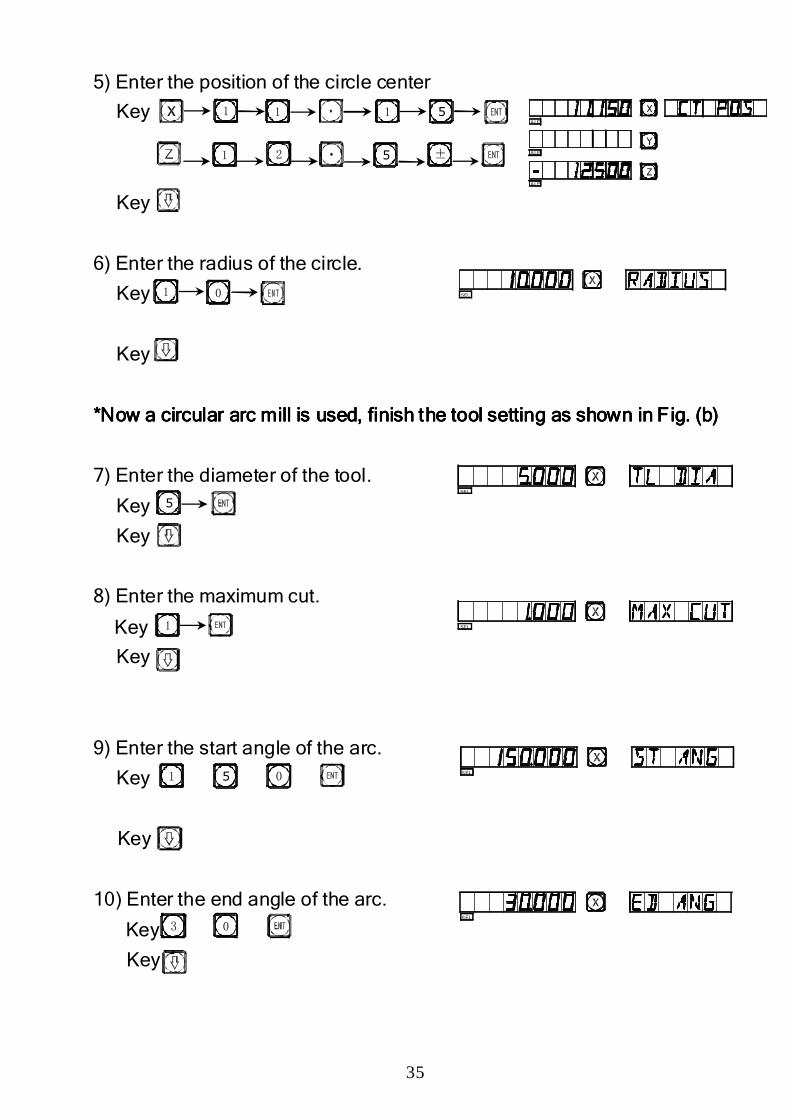
5) Enter the position of the circle center
Key
Key
6) Enter the radius of the circle.
Key
Key
*Now a circular arc mill is used, finish the tool setting as shown in Fig. (b)*Now a circular arc mill is used, finish the tool setting as shown in Fig. (b)*Now a circular arc mill is used, finish the tool setting as shown in Fig. (b)*Now a circular arc mill is used, finish the tool setting as shown in Fig. (b)
7) Enter the diameter of the tool.
Key
Key
8) Enter the maximum cut.
Key
Key
9) Enter the start angle of the arc.
Key
Key
10) Enter the end angle of the arc.
Key
Key
1
1
11
2
5
5 ±
1 0
5
1
1 5 0
3 0
SEL
SEL
SEL
SEL
SEL
Z
Y
X
ALE
ALE
ALE
36
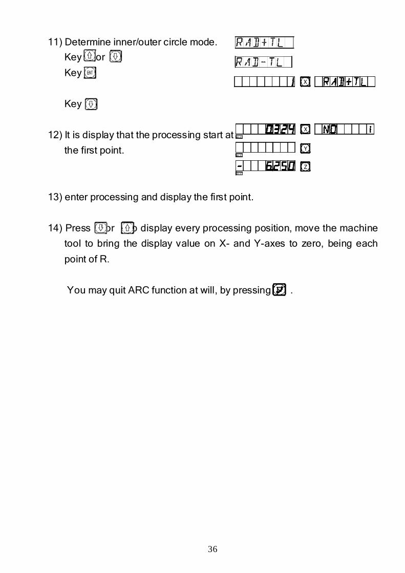
11) Determine inner/outer circle mode.
Key or
Key
Key
12) It is display that the processing start at
the first point.
13) enter processing and display the first point.
14) Press or to display every processing position, move the machine
tool to bring the display value on X- and Y-axes to zero, being each
point of R.
You may quit ARC function at will, by pressing .
R
Z
Y
X
ALE
ALE
ALE
X

37
C.C.C.C.
Simple RSimple RSimple RSimple R
38
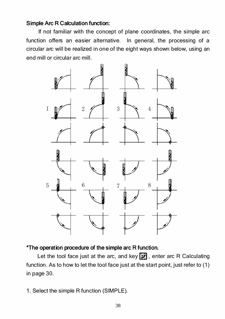
Simple Arc R Calculation function:Simple Arc R Calculation function:Simple Arc R Calculation function:Simple Arc R Calculation function:
If not familiar with the concept of plane coordinates, the simple arc
function offers an easier alternative. In general, the processing of a
circular arc will be realized in one of the eight ways shown below, using an
end mill or circular arc mill.
*The operation procedure of the simple arc R function.*The operation procedure of the simple arc R function.*The operation procedure of the simple arc R function.*The operation procedure of the simple arc R function.
Let the tool face just at the arc, and key , enter arc R Calculating
function. As to how to let the tool face just at the start point, just refer to (1)
in page 30.
1. Select the simple R function (SIMPLE).
R
5 6 7 8
1 2 3 4
39
Fig. (a)
MAX CUT
Fig. (b)
MAX CUT
R10
B
φ5
A
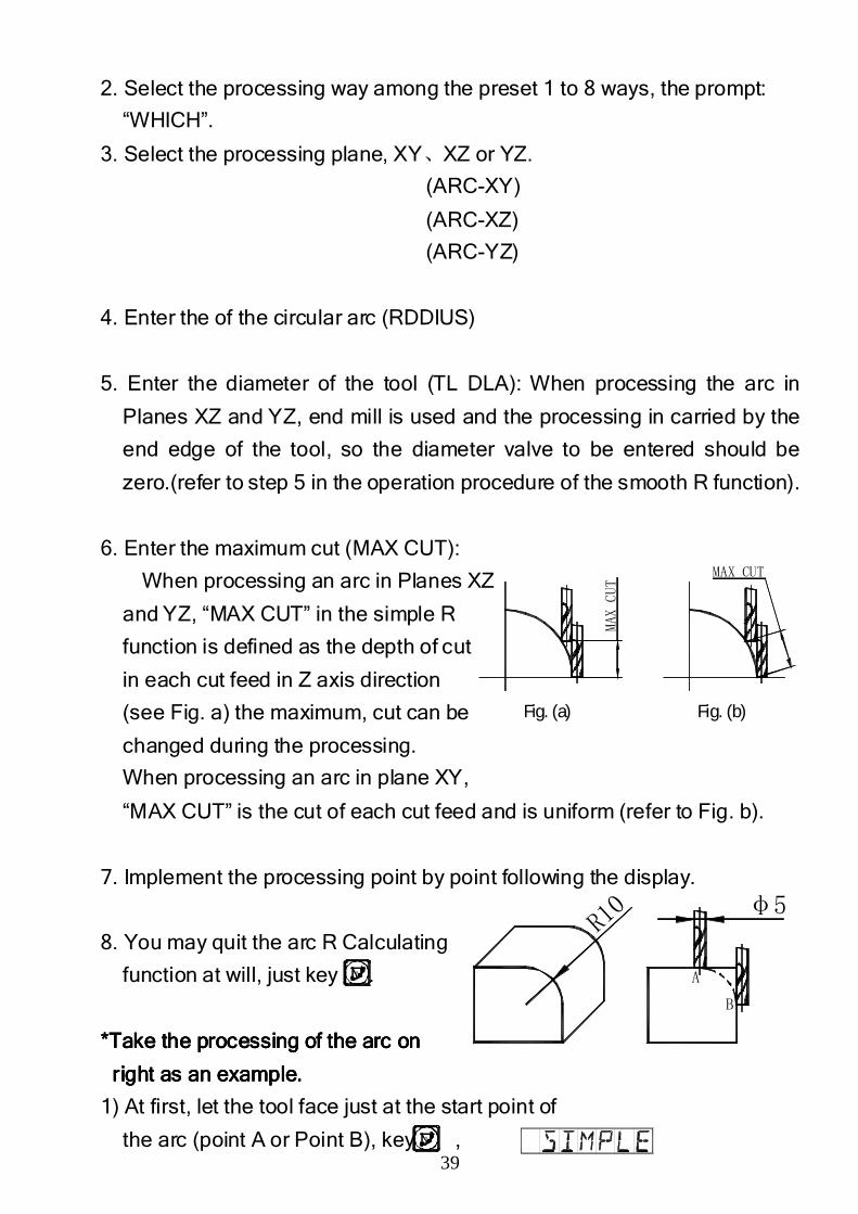
2. Select the processing way among the preset 1 to 8 ways, the prompt:
“WHICH”.
3. Select the processing plane, XY、XZ or YZ.
(ARC-XY)
(ARC-XZ)
(ARC-YZ)
4. Enter the of the circular arc (RDDIUS)
5. Enter the diameter of the tool (TL DLA): When processing the arc in
Planes XZ and YZ, end mill is used and the processing in carried by the
end edge of the tool, so the diameter valve to be entered should be
zero.(refer to step 5 in the operation procedure of the smooth R function).
6. Enter the maximum cut (MAX CUT):
When processing an arc in Planes XZ
and YZ, “MAX CUT” in the simple R
function is defined as the depth of cut
in each cut feed in Z axis direction
(see Fig. a) the maximum, cut can be
changed during the processing.
When processing an arc in plane XY,
“MAX CUT” is the cut of each cut feed and is uniform (refer to Fig. b).
7. Implement the processing point by point following the display.
8. You may quit the arc R Calculating
function at will, just key .
*Take the processing of the arc on *Take the processing of the arc on *Take the processing of the arc on *Take the processing of the arc on
right as an example.right as an example.right as an example.right as an example.
1) At first, let the tool face just at the start point of
the arc (point A or Point B), key ,
R
R
40
L
R R
L
R
L
R L
R L
R
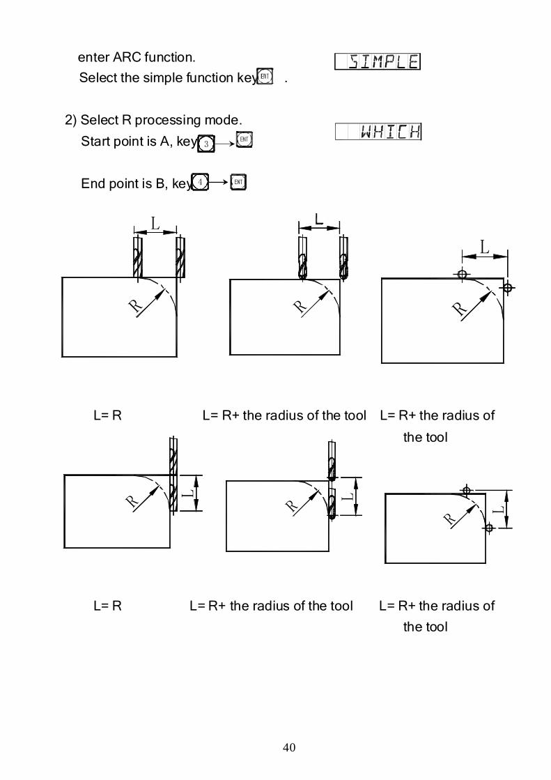
enter ARC function.
Select the simple function key .
2) Select R processing mode.
Start point is A, key
End point is B, key
L= R L= R+ the radius of the tool L= R+ the radius of
the tool
L= R L= R+ the radius of the tool L= R+ the radius of
the tool
4
3
41
L
R
L1
L2
R L2
L1
R
L
R
L1
L2
R
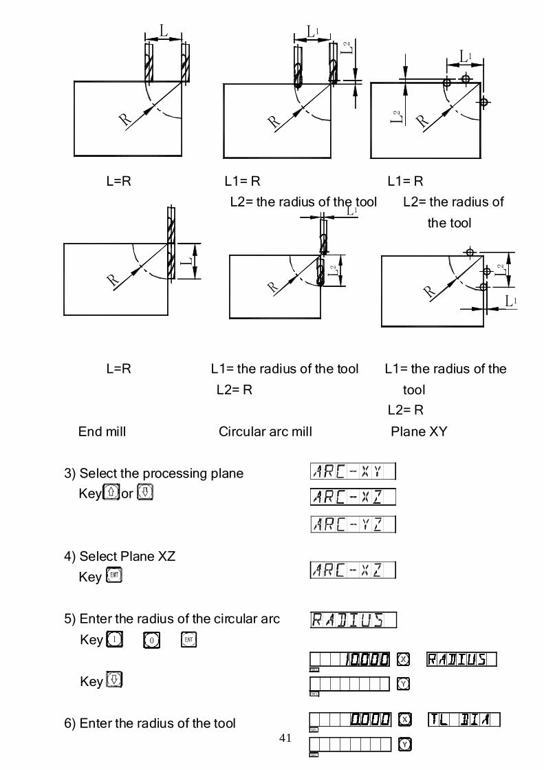
L=R L1= R L1= R
L2= the radius of the tool L2= the radius of
the tool
L=R L1= the radius of the tool L1= the radius of the
L2= R tool
L2= R
End mill Circular arc mill Plane XY
3) Select the processing plane
Key or
4) Select Plane XZ
Key
5) Enter the radius of the circular arc
Key
Key
6) Enter the radius of the tool
1 0
SEL
SEL
SEL
SEL
L2
R L1
42
R10 A
B
Key
Key
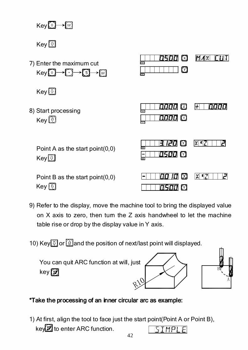
7) Enter the maximum cut
Key
Key
8) Start processing
Key
Point A as the start point(0,0)
Key
Point B as the start point(0,0)
Key
9) Refer to the display, move the machine tool to bring the displayed value
on X axis to zero, then turn the Z axis handwheel to let the machine
table rise or drop by the display value in Y axis.
10) Key or and the position of next/last point will displayed.
You can quit ARC function at will, just
key
*Take the processing of an inner circular arc as example:*Take the processing of an inner circular arc as example:*Take the processing of an inner circular arc as example:*Take the processing of an inner circular arc as example:
1) At first, align the tool to face just the start point(Point A or Point B),
key to enter ARC function.
0
0 5
R
SEL
SEL
SEL
SEL
SEL
SEL
R
43
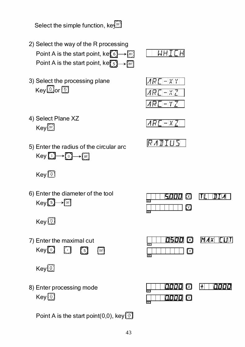
Select the simple function, key
2) Select the way of the R processing
Point A is the start point, key
Point A is the start point, key
3) Select the processing plane
Key or
4) Select Plane XZ
Key
5) Enter the radius of the circular arc
Key
Key
6) Enter the diameter of the tool
Key
Key
7) Enter the maximal cut
Key
Key
8) Enter processing mode
Key
Point A is the start point(0,0), key
5
6
01
5
0 5
SE L
SE L
SEL
SEL
SEL
SEL
SEL
SEL
44
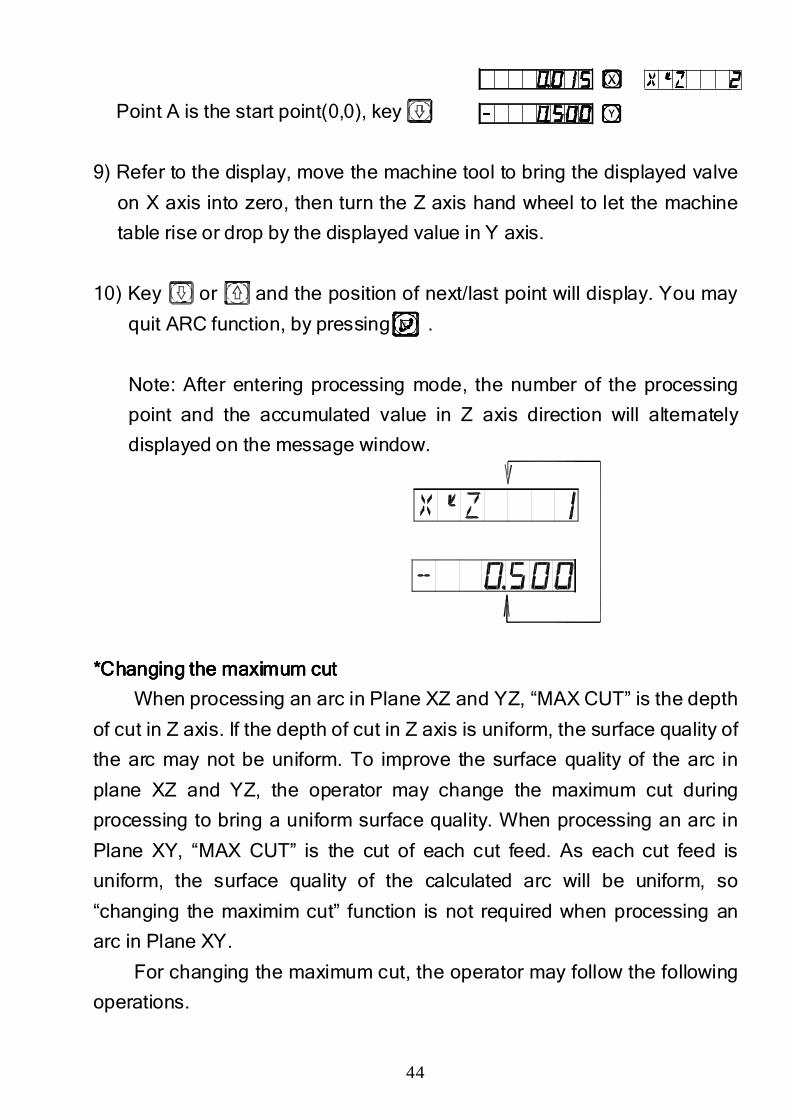
Point A is the start point(0,0), key
9) Refer to the display, move the machine tool to bring the displayed valve
on X axis into zero, then turn the Z axis hand wheel to let the machine
table rise or drop by the displayed value in Y axis.
10) Key or and the position of next/last point will display. You may
quit ARC function, by pressing .
Note: After entering processing mode, the number of the processing
point and the accumulated value in Z axis direction will alternately
displayed on the message window.
*Changing the *Changing the *Changing the *Changing the maximummaximummaximummaximum cutcutcutcut
When processing an arc in Plane XZ and YZ, “MAX CUT” is the depth
of cut in Z axis. If the depth of cut in Z axis is uniform, the surface quality of
the arc may not be uniform. To improve the surface quality of the arc in
plane XZ and YZ, the operator may change the maximum cut during
processing to bring a uniform surface quality. When processing an arc in
Plane XY, “MAX CUT” is the cut of each cut feed. As each cut feed is
uniform, the surface quality of the calculated arc will be uniform, so
“changing the maximim cut” function is not required when processing an
arc in Plane XY.
For changing the maximum cut, the operator may follow the following
operations.
R
45
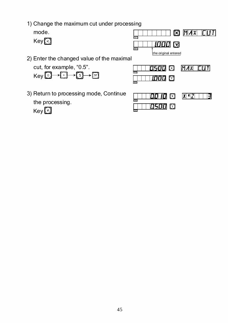
1) Change the maximum cut under processing
mode.
Key
2) Enter the changed value of the maximal
cut, for example, “0.5”.
Key
3) Return to processing mode, Continue
the processing.
Key
12
0 5
12
SEL
SEL
S EL
S EL
SEL
SEL
the original entered

46
D.D.D.D.
Hole Drilling Along An Oblique LineHole Drilling Along An Oblique LineHole Drilling Along An Oblique LineHole Drilling Along An Oblique Line
((((
47
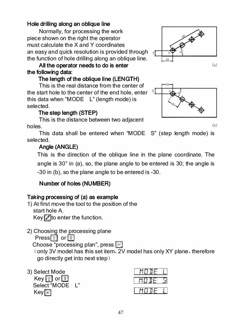
HoHoHoHole drilling along an oblique linele drilling along an oblique linele drilling along an oblique linele drilling along an oblique line Normally, for processing the work
piece shown on the right the operator must calculate the X and Y coordinates an easy and quick resolution is provided through the function of hole drilling along an oblique line.
All the All the All the All the operator operator operator operator needs to do is enterneeds to do is enterneeds to do is enterneeds to do is enter the following data:the following data:the following data:the following data:
The length of the The length of the The length of the The length of the oblique lineoblique lineoblique lineoblique line (LENGTH)(LENGTH)(LENGTH)(LENGTH) This is the real distance from the center of
the start hole to the center of the end hole, enter this data when “MODE L” (length mode) is selected.
The step length (STEP)The step length (STEP)The step length (STEP)The step length (STEP) This is the distance between two adjacent
holes. This data shall be entered when “MODE S” (step length mode) is
selected. Angle (ANGLE)Angle (ANGLE)Angle (ANGLE)Angle (ANGLE)
This is the direction of the oblique line in the plane coordinate. The
angle is 30° in (a), so, the plane angle to be entered is 30; the angle is
-30 in (b), so the plane angle to be entered is -30.
Number of holes (NUMBER)Number of holes (NUMBER)Number of holes (NUMBER)Number of holes (NUMBER) Taking Taking Taking Taking processing of (a) as exampleprocessing of (a) as exampleprocessing of (a) as exampleprocessing of (a) as example 1) At first move the tool to the position of the
start hole A. Key to enter the function.
2) Choosing the processing plane Press or Choose “processing plan”, press (only 3V model has this set item,2V model has only XY plane,therefore
go directly get into next step) 3) Select Mode
Key or Select “MODE L” Key
(b)
(a)
A
A
30°
30°
60
10
20
10
20
20
48
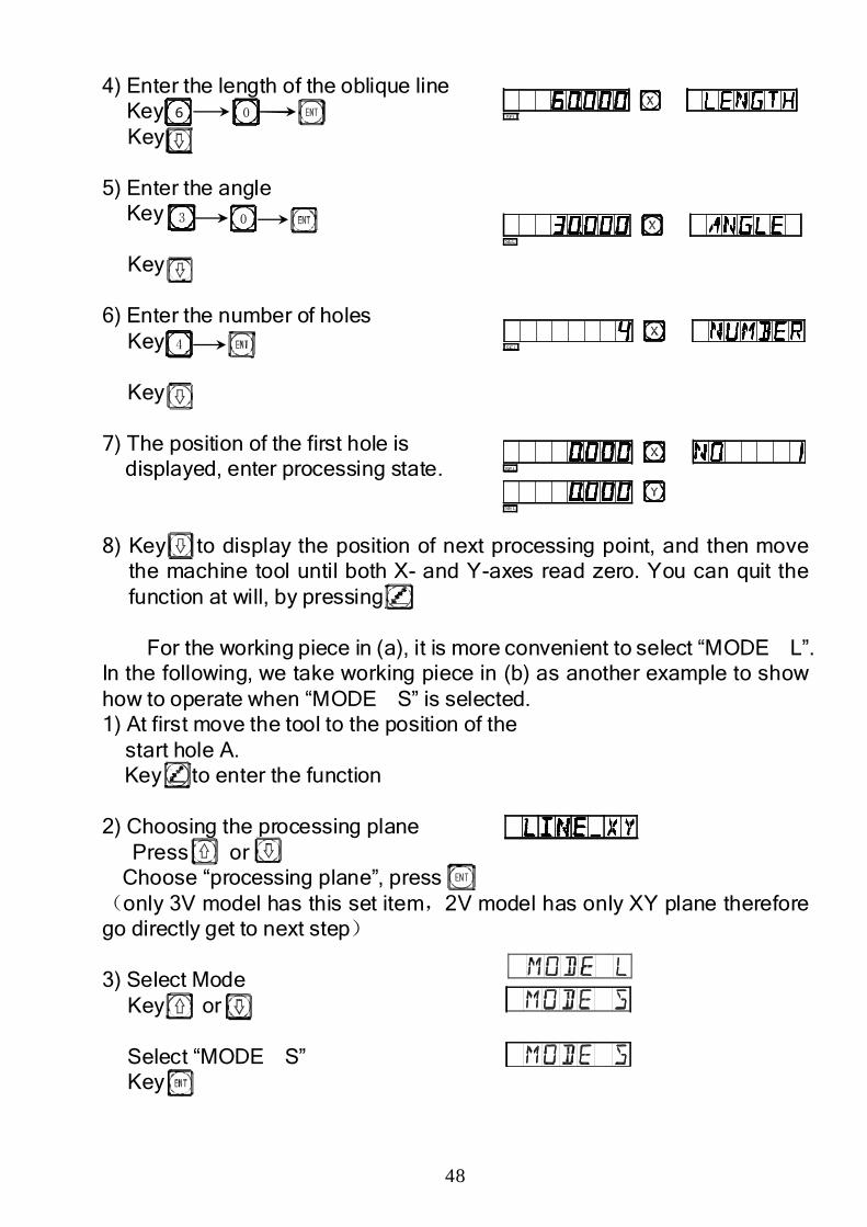
4) Enter the length of the oblique line Key Key
5) Enter the angle
Key
Key
6) Enter the number of holes Key
Key
7) The position of the first hole is
displayed, enter processing state. 8) Key to display the position of next processing point, and then move
the machine tool until both X- and Y-axes read zero. You can quit the function at will, by pressing
For the working piece in (a), it is more convenient to select “MODE L”.
In the following, we take working piece in (b) as another example to show how to operate when “MODE S” is selected. 1) At first move the tool to the position of the
start hole A. Key to enter the function
2) Choosing the processing plane Press or Choose “processing plane”, press (only 3V model has this set item,2V model has only XY plane therefore go directly get to next step) 3) Select Mode
Key or
Select “MODE S” Key
6 0
03
4
SEL
SEL
SEL
SEL
SEL
49
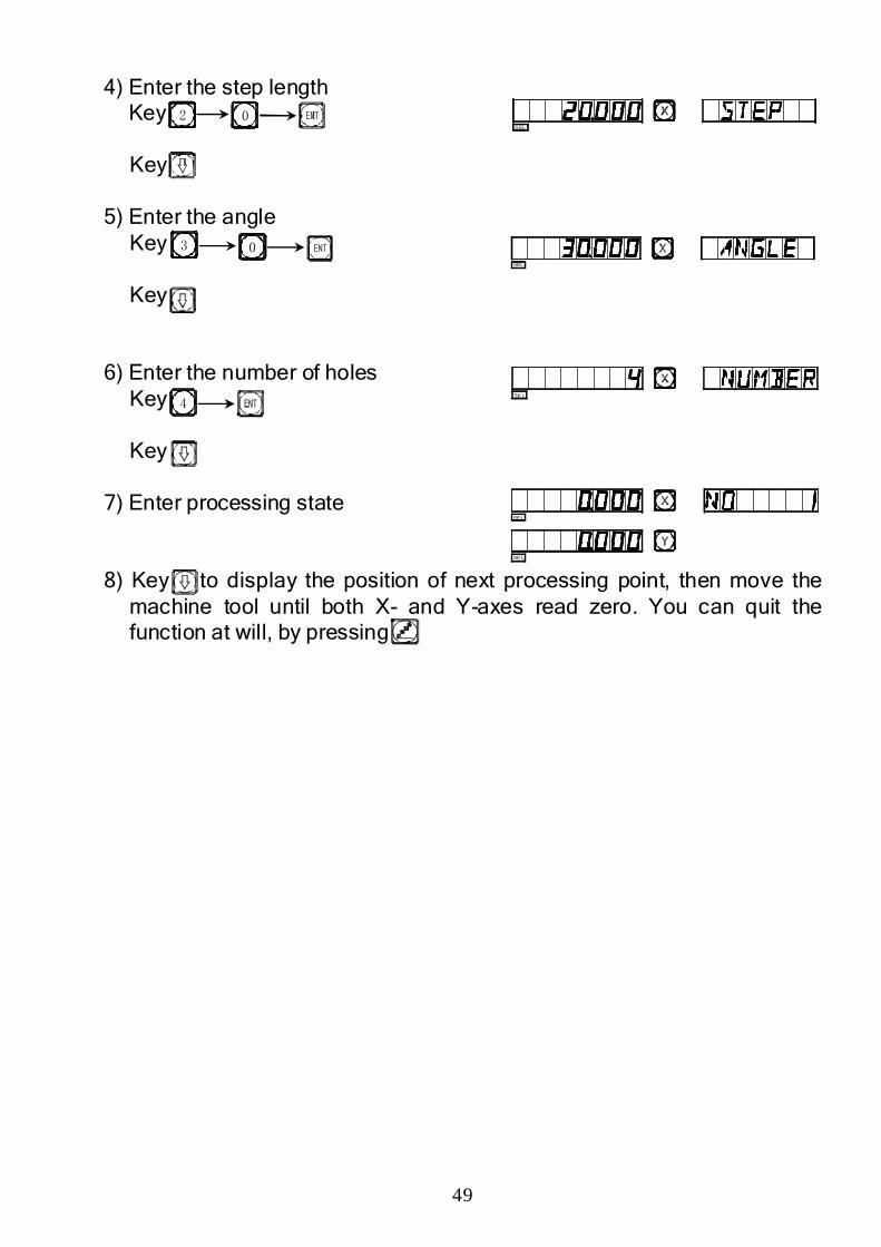
4) Enter the step length Key Key
5) Enter the angle
Key
Key
6) Enter the number of holes Key
Key
7) Enter processing state 8) Key to display the position of next processing point, then move the
machine tool until both X- and Y-axes read zero. You can quit the function at will, by pressing
2 0
3 0
4
SEL
SEL
SEL
SEL
SEL

50
EEEE1111
200 Point Subsidiary Zero Positions200 Point Subsidiary Zero Positions200 Point Subsidiary Zero Positions200 Point Subsidiary Zero Positions
51
200 zero position 200 zero position 200 zero position 200 zero position memory memory memory memory function:function:function:function:
200 zero position function: also called 200 user Coordinate System
(UCS) function.
ALE: Absolute Coordinate System.
ALE is the “reference” system. All 200 UCS positions are defined
relative to the ALE. ALE is confirmed in the initialization of the work piece,
which doesn’t change if the work piece is not changed.
UCS: User Coordinate System.
Certain large parts / drawings of complicated drilling/milling fittings
have multiple zero reference points. In such cases the ability to set
multiple zero datums increases work efficiency.
ⅠⅠⅠⅠ. The operator must know the following two key points before making use . The operator must know the following two key points before making use . The operator must know the following two key points before making use . The operator must know the following two key points before making use
of this function: of this function: of this function: of this function:
1. Every subsidiary zero position is the origin datum point of one UCS.
Once entering the display mode of a UCS, the display of every point will
take the subsidiary zero position as the original datum point.
2. Each subsidiary zero position is relative to the zero position in absolute
mode (ALE). After a subsidiary zero position is set, the DRO will keep
the position relation between with zero position in the absolute mode in
memory, if zero position in the absolute mode changes, the subsidiary
zero position will also change by the same distance and angle.
ⅡⅡⅡⅡ. The operator may . The operator may . The operator may . The operator may use this function as followsuse this function as followsuse this function as followsuse this function as follows::::
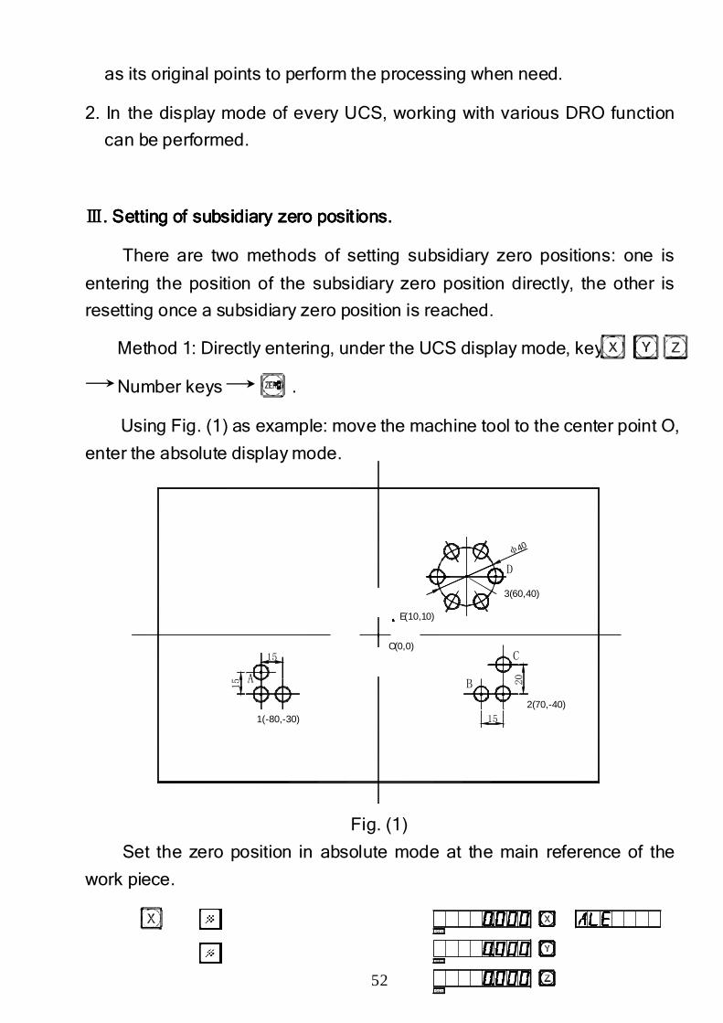
1. Set the zero position in absolute mode (ALE lamp on) at the main
reference point of the working piece, for example, Point O in Fig. (1) in
next page. Set subsidiary zero positions at subsidiary reference points of
the working piece, for example, Points 1, 2 and 3 in Fig. (1). It is possible
to enter the display mode of every UCS taking a subsidiary zero position
52
φ40
15
20
15
15
A
C
B
D
E(10,10)
O(0,0)
3(60,40)
2(70,-40)
1(-80,-30)
as its original points to perform the processing when need.
2. In the display mode of every UCS, working with various DRO function
can be performed.
ⅢⅢⅢⅢ. S. S. S. Setting of subsidiary zero positionetting of subsidiary zero positionetting of subsidiary zero positionetting of subsidiary zero positions.s.s.s.
There are two methods of setting subsidiary zero positions: one is
entering the position of the subsidiary zero position directly, the other is
resetting once a subsidiary zero position is reached.
Method 1: Directly entering, under the UCS display mode, key
Number keys .
Using Fig. (1) as example: move the machine tool to the center point O,
enter the absolute display mode.
Fig. (1)
Set the zero position in absolute mode at the main reference of the
work piece.
SEL
SEL
SEL
53
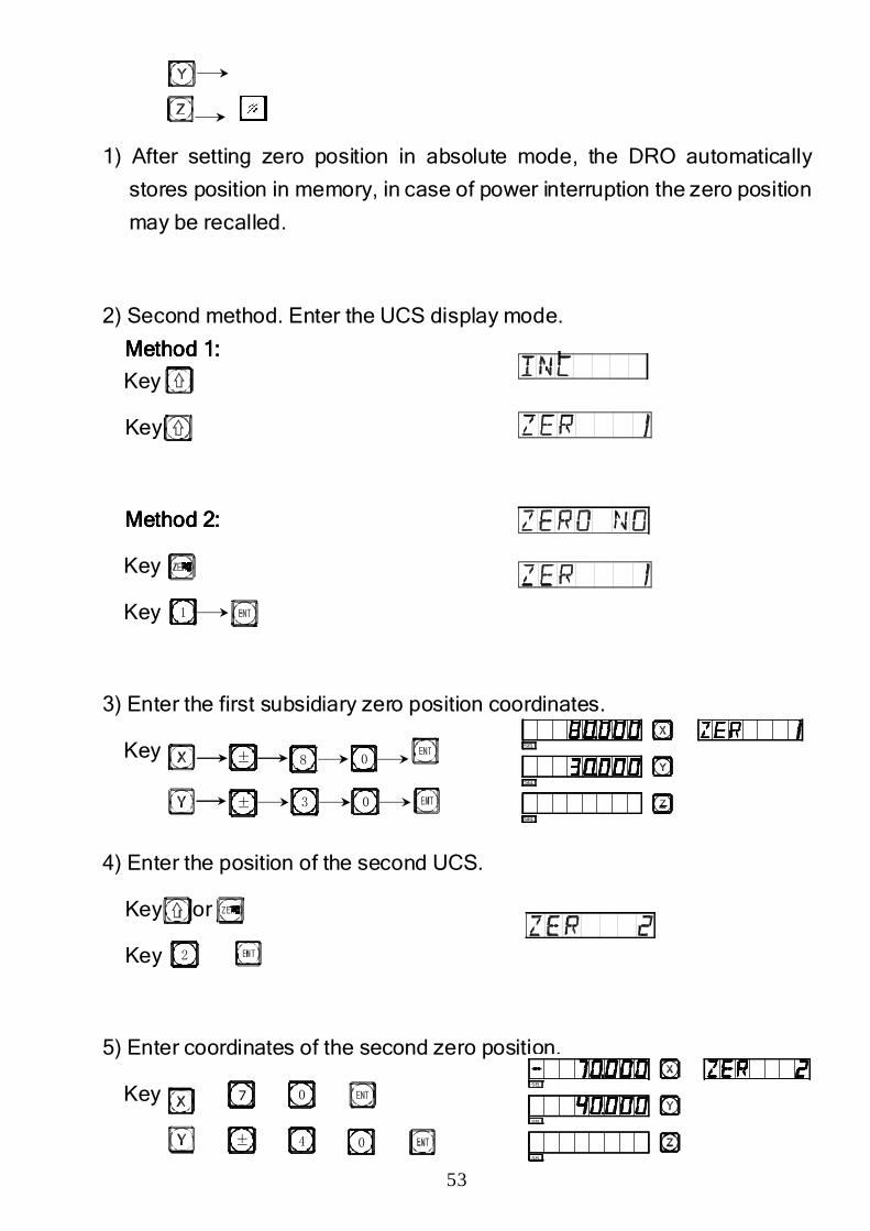
1) After setting zero position in absolute mode, the DRO automatically
stores position in memory, in case of power interruption the zero position
may be recalled.
2) Second method. Enter the UCS display mode.
Method 1:Method 1:Method 1:Method 1:
Key
Key
Method 2:Method 2:Method 2:Method 2:
Key
Key
3) Enter the first subsidiary zero position coordinates.
Key
4) Enter the position of the second UCS.
Key or
Key
5) Enter coordinates of the second zero position.
Key
1
±
±
8
3 0
0
2
7
0
0
± 4
SEL
SEL
SEL
SEL
SEL
SEL
54
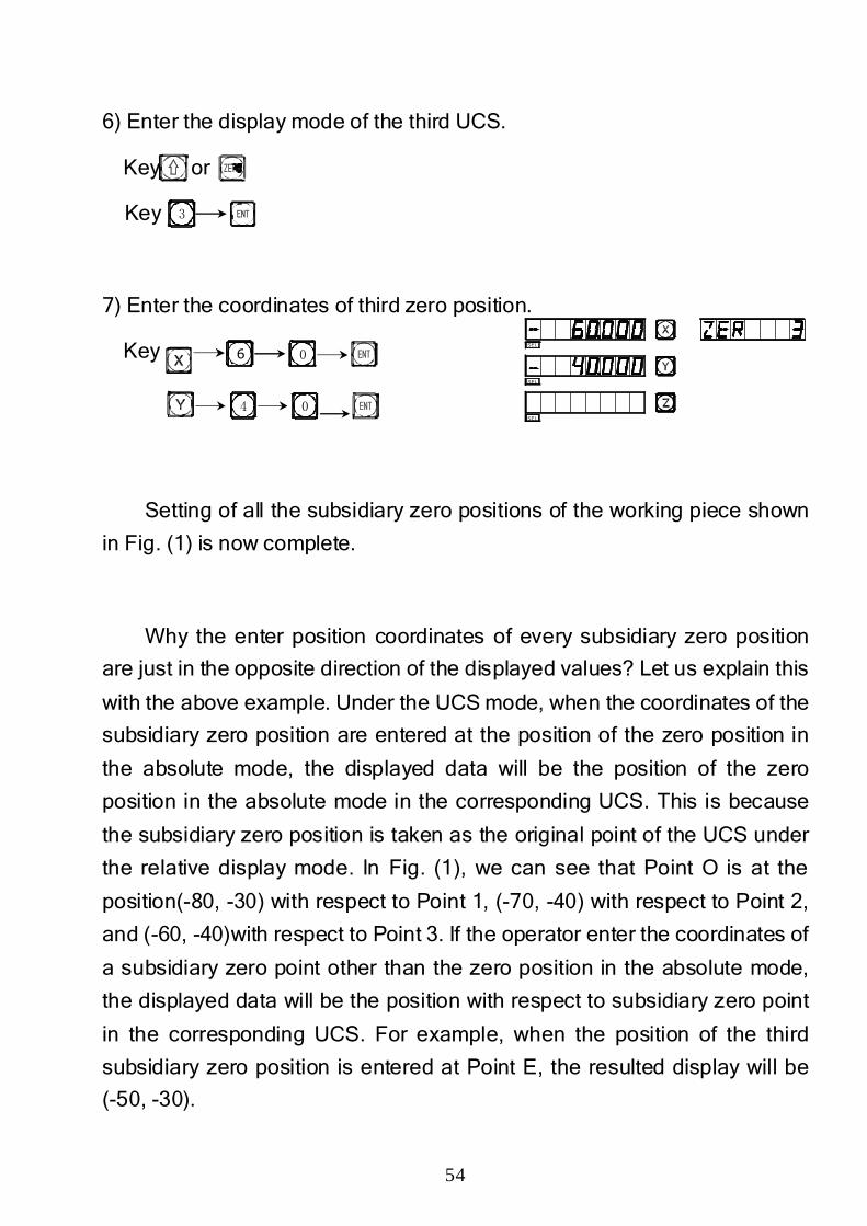
6) Enter the display mode of the third UCS.
Key or
Key
7) Enter the coordinates of third zero position.
Key
Setting of all the subsidiary zero positions of the working piece shown
in Fig. (1) is now complete.
Why the enter position coordinates of every subsidiary zero position
are just in the opposite direction of the displayed values? Let us explain this
with the above example. Under the UCS mode, when the coordinates of the
subsidiary zero position are entered at the position of the zero position in
the absolute mode, the displayed data will be the position of the zero
position in the absolute mode in the corresponding UCS. This is because
the subsidiary zero position is taken as the original point of the UCS under
the relative display mode. In Fig. (1), we can see that Point O is at the
position(-80, -30) with respect to Point 1, (-70, -40) with respect to Point 2,
and (-60, -40)with respect to Point 3. If the operator enter the coordinates of
a subsidiary zero point other than the zero position in the absolute mode,
the displayed data will be the position with respect to subsidiary zero point
in the corresponding UCS. For example, when the position of the third
subsidiary zero position is entered at Point E, the resulted display will be
(-50, -30).
0
0
3
4
6SEL
SEL
SEL
55
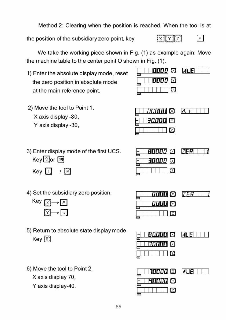
Method 2: Clearing when the position is reached. When the tool is at
the position of the subsidiary zero point, key .
We take the working piece shown in Fig. (1) as example again: Move
the machine table to the center point O shown in Fig. (1).
1) Enter the absolute display mode, reset
the zero position in absolute mode
at the main reference point.
2) Move the tool to Point 1.
X axis display -80,
Y axis display -30,
3) Enter display mode of the first UCS.
Key or
Key
4) Set the subsidiary zero position.
Key
5) Return to absolute state display mode
Key
6) Move the tool to Point 2.
X axis display 70,
Y axis display-40.
1
SEL
SEL
SEL
SEL
SEL
SEL
SEL
SEL
SEL
SEL
SEL
SEL
SEL
SEL
SEL
SEL
SEL
SEL
56
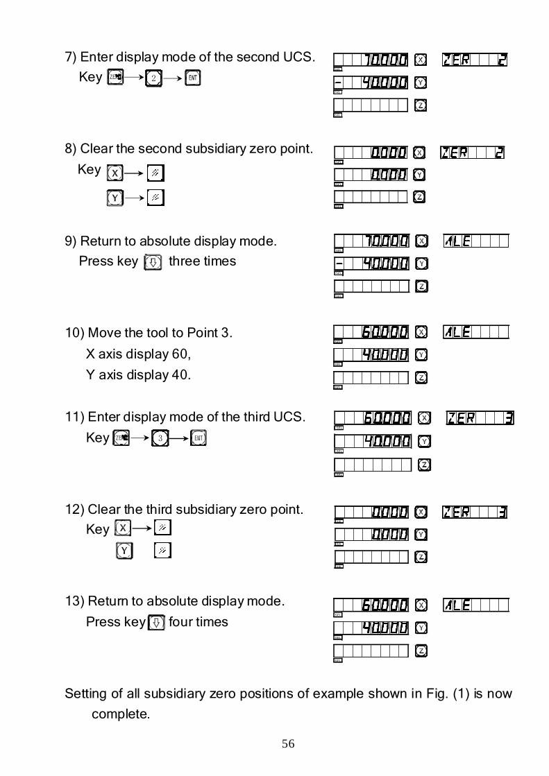
7) Enter display mode of the second UCS.
Key
8) Clear the second subsidiary zero point.
Key
9) Return to absolute display mode.
Press key three times
10) Move the tool to Point 3.
X axis display 60,
Y axis display 40.
11) Enter display mode of the third UCS.
Key
12) Clear the third subsidiary zero point.
Key
13) Return to absolute display mode.
Press key four times
Setting of all subsidiary zero positions of example shown in Fig. (1) is now
complete.
2
3
SEL
SEL
SEL
SEL
SEL
SEL
SEL
SEL
SEL
SEL
SEL
SEL
SEL
SEL
SEL
SEL
SEL
SEL
SEL
SEL
SEL
57
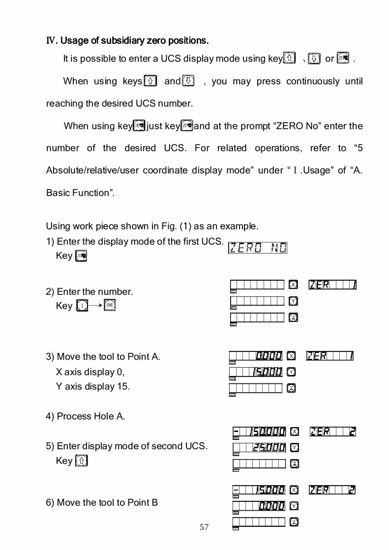
ⅣⅣⅣⅣ. U. U. U. Usage of subsidiary zero positions.sage of subsidiary zero positions.sage of subsidiary zero positions.sage of subsidiary zero positions.
It is possible to enter a UCS display mode using key 、 or .
When using keys and , you may press continuously until
reaching the desired UCS number.
When using key just key and at the prompt “ZERO No” enter the
number of the desired UCS. For related operations, refer to “5
Absolute/relative/user coordinate display mode” under “Ⅰ.Usage” of “A.
Basic Function”.
Using work piece shown in Fig. (1) as an example.
1) Enter the display mode of the first UCS.
Key
2) Enter the number.
Key
3) Move the tool to Point A.
X axis display 0,
Y axis display 15.
4) Process Hole A.
5) Enter display mode of second UCS.
Key
6) Move the tool to Point B
1
SEL
SEL
SEL
SEL
SEL
SEL
SEL
SEL
SEL
SEL
SEL
SEL
58
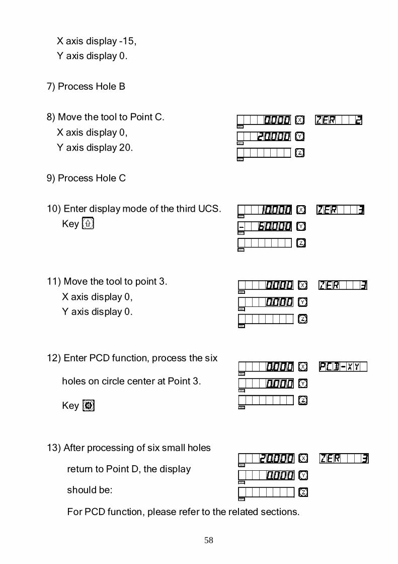
X axis display -15,
Y axis display 0.
7) Process Hole B
8) Move the tool to Point C.
X axis display 0,
Y axis display 20.
9) Process Hole C
10) Enter display mode of the third UCS.
Key
11) Move the tool to point 3.
X axis display 0,
Y axis display 0.
12) Enter PCD function, process the six
holes on circle center at Point 3.
Key
13) After processing of six small holes
return to Point D, the display
should be:
For PCD function, please refer to the related sections.
SEL
SEL
SEL
SEL
SEL
SEL
SEL
SEL
SEL
SEL
SEL
SEL
SEL
SEL
SEL
59
ⅤⅤⅤⅤ. Clearing of Subsidiary Zero Positions and Other . Clearing of Subsidiary Zero Positions and Other . Clearing of Subsidiary Zero Positions and Other . Clearing of Subsidiary Zero Positions and Other
Related Problems.Related Problems.Related Problems.Related Problems.
1. Clearing of Subsidiary zero positions1. Clearing of Subsidiary zero positions1. Clearing of Subsidiary zero positions1. Clearing of Subsidiary zero positions
In absolute state (ALE state), key 10 times continuously, the
memory of all subsidiary zero positions will be cleared.
2. Reset during a subsid2. Reset during a subsid2. Reset during a subsid2. Reset during a subsidiary zero position while in useiary zero position while in useiary zero position while in useiary zero position while in use
When a subsidiary zero position is being used (UCS #), resetting in
this state will set a new subsidiary zero position. The point at which
resetting is performed will become the new subsidiary zero position
replacing the original.
3. 3. 3. 3. Halving (centering) during use of a Halving (centering) during use of a Halving (centering) during use of a Halving (centering) during use of a subsidsubsidsubsidsubsidiary zero position.iary zero position.iary zero position.iary zero position.
“1/2” function may be used under UCS display mode. Centering under
UCS display mode will actually set a new subsidiary zero position. After
centering, the original subsidiary zero position will be replaced by the new
subsidiary zero, centered between the original subsidiary zero position and
the point at which centering was performed.

60
EEEE2222
200 Point200 Point200 Point200 Point Subsidiary Zero PositionsSubsidiary Zero PositionsSubsidiary Zero PositionsSubsidiary Zero Positions
((((LATHELATHELATHELATHE))))
61
155
40
70
φ40
φ71
φ60
φ40
φ20
25
103(20,-130)
2(30,-120) 1(20,-70)
X
O(0,0)
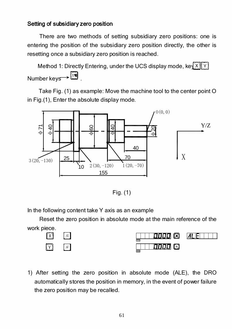
SSSSetting of subsidiary zero positionetting of subsidiary zero positionetting of subsidiary zero positionetting of subsidiary zero position
There are two methods of setting subsidiary zero positions: one is
entering the position of the subsidiary zero position directly, the other is
resetting once a subsidiary zero position is reached.
Method 1: Directly Entering, under the UCS display mode, key
Number keys .
Take Fig. (1) as example: Move the machine tool to the center point O
in Fig.(1), Enter the absolute display mode.
Fig. (1)
In the following content take Y axis as an example
Reset the zero position in absolute mode at the main reference of the
work piece.
1) After setting the zero position in absolute mode (ALE), the DRO
automatically stores the position in memory, in the event of power failure
the zero position may be recalled.
SEL
SEL
ZZ0
Y/Z
62
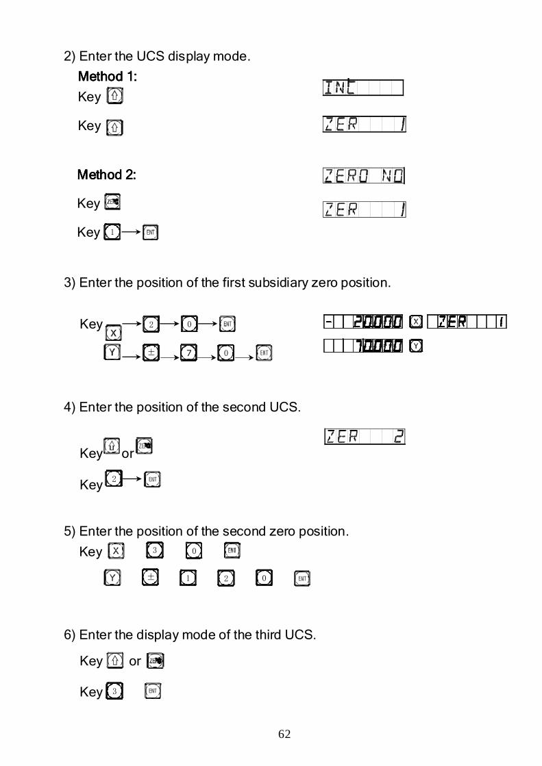
2) Enter the UCS display mode.
Method 1:Method 1:Method 1:Method 1:
Key
Key
Method 2:Method 2:Method 2:Method 2:
Key
Key
3) Enter the position of the first subsidiary zero position.
Key
4) Enter the position of the second UCS.
Key or
Key
5) Enter the position of the second zero position.
Key
6) Enter the display mode of the third UCS.
Key or
Key
2 0
± 7 0
2
2
0
± 1 0
3
3
1
63
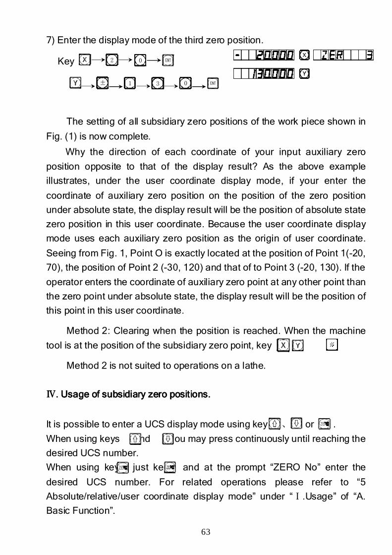
7) Enter the display mode of the third zero position.
Key
The setting of all subsidiary zero positions of the work piece shown in
Fig. (1) is now complete.
Why the direction of each coordinate of your input auxiliary zero
position opposite to that of the display result? As the above example
illustrates, under the user coordinate display mode, if your enter the
coordinate of auxiliary zero position on the position of the zero position
under absolute state, the display result will be the position of absolute state
zero position in this user coordinate. Because the user coordinate display
mode uses each auxiliary zero position as the origin of user coordinate.
Seeing from Fig. 1, Point O is exactly located at the position of Point 1(-20,
70), the position of Point 2 (-30, 120) and that of to Point 3 (-20, 130). If the
operator enters the coordinate of auxiliary zero point at any other point than
the zero point under absolute state, the display result will be the position of
this point in this user coordinate.
Method 2: Clearing when the position is reached. When the machine
tool is at the position of the subsidiary zero point, key .
Method 2 is not suited to operations on a lathe.
ⅣⅣⅣⅣ. U. U. U. Usage of subsidiary zero positions.sage of subsidiary zero positions.sage of subsidiary zero positions.sage of subsidiary zero positions.
It is possible to enter a UCS display mode using key 、 or .
When using keys and , you may press continuously until reaching the
desired UCS number.
When using key just key and at the prompt “ZERO No” enter the
desired UCS number. For related operations please refer to “5
Absolute/relative/user coordinate display mode” under “Ⅰ.Usage” of “A.
Basic Function”.
2 0
± 1 3 0
64
A(0,0)
C25
D
0.8
BX
0.8
0.8
155
10
φ71
φ40
φ60
70
40
φ20
φ40
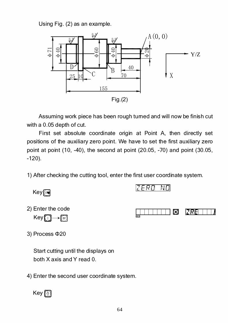
Using Fig. (2) as an example.
Fig.(2)
Assuming work piece has been rough turned and will now be finish cut
with a 0.05 depth of cut.
First set absolute coordinate origin at Point A, then directly set
positions of the auxiliary zero point. We have to set the first auxiliary zero
point at point (10, -40), the second at point (20.05, -70) and point (30.05,
-120).
1) After checking the cutting tool, enter the first user coordinate system.
Key
2) Enter the code
Key
3) Process Φ20
Start cutting until the displays on
both X axis and Y read 0.
4) Enter the second user coordinate system.
Key
1SEL
Y/Z
65
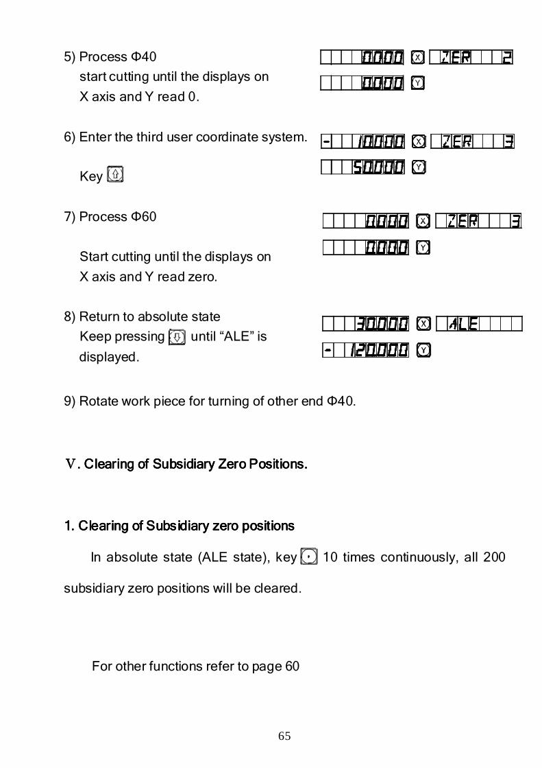
5) Process Φ40
start cutting until the displays on
X axis and Y read 0.
6) Enter the third user coordinate system.
Key
7) Process Φ60
Start cutting until the displays on
X axis and Y read zero.
8) Return to absolute state
Keep pressing until “ALE” is
displayed.
9) Rotate work piece for turning of other end Φ40.
ⅤⅤⅤⅤ. . . . Clearing of Subsidiary Zero Positions.Clearing of Subsidiary Zero Positions.Clearing of Subsidiary Zero Positions.Clearing of Subsidiary Zero Positions.
1. Clearing of Subsidiary zero positions1. Clearing of Subsidiary zero positions1. Clearing of Subsidiary zero positions1. Clearing of Subsidiary zero positions
In absolute state (ALE state), key 10 times continuously, all 200
subsidiary zero positions will be cleared.
For other functions refer to page 60

66
EEEE3333
200 Point Subsidiary Zero Positions200 Point Subsidiary Zero Positions200 Point Subsidiary Zero Positions200 Point Subsidiary Zero Positions
((((GrindingGrindingGrindingGrinding))))
67
25
5050
150
45
5
10
1(-5,25)
2(-10,75) 3(-10,100)
E AC B
D0(0,0)
X
Y
grinding wheel
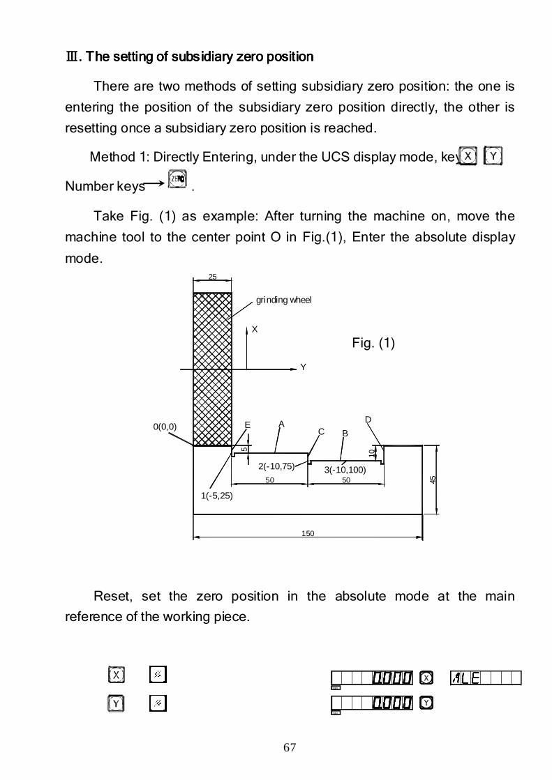
ⅢⅢⅢⅢ. The setting of subsidiary. The setting of subsidiary. The setting of subsidiary. The setting of subsidiary zero positionzero positionzero positionzero position
There are two methods of setting subsidiary zero position: the one is
entering the position of the subsidiary zero position directly, the other is
resetting once a subsidiary zero position is reached.
Method 1: Directly Entering, under the UCS display mode, key
Number keys .
Take Fig. (1) as example: After turning the machine on, move the
machine tool to the center point O in Fig.(1), Enter the absolute display
mode.
Fig. (1)
Reset, set the zero position in the absolute mode at the main
reference of the working piece.
SEL
SEL
68
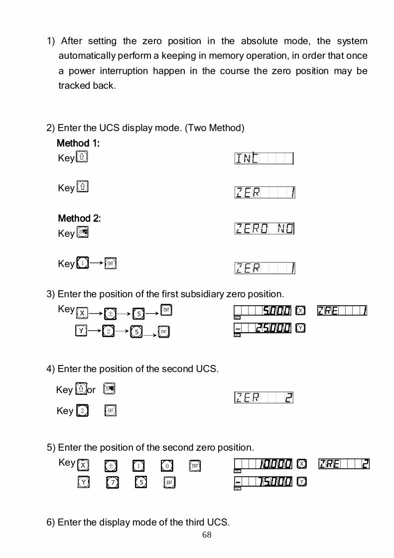
1) After setting the zero position in the absolute mode, the system
automatically perform a keeping in memory operation, in order that once
a power interruption happen in the course the zero position may be
tracked back.
2) Enter the UCS display mode. (Two Method)
Method 1:Method 1:Method 1:Method 1:
Key
Key
Method 2:Method 2:Method 2:Method 2:
Key
Key
3) Enter the position of the first subsidiary zero position.
Key
4) Enter the position of the second UCS.
Key or
Key
5) Enter the position of the second zero position.
Key
6) Enter the display mode of the third UCS.
1
± 5
52
7 5
± 01
SE L
SE L
SEL
SEL
2
69
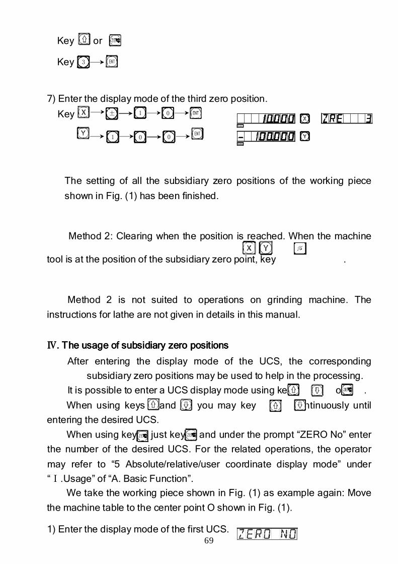
Key or
Key
7) Enter the display mode of the third zero position.
Key
The setting of all the subsidiary zero positions of the working piece
shown in Fig. (1) has been finished.
Method 2: Clearing when the position is reached. When the machine
tool is at the position of the subsidiary zero point, key .
Method 2 is not suited to operations on grinding machine. The
instructions for lathe are not given in details in this manual.
ⅣⅣⅣⅣ. The usage of subsidiary zero positions. The usage of subsidiary zero positions. The usage of subsidiary zero positions. The usage of subsidiary zero positions
After entering the display mode of the UCS, the corresponding
subsidiary zero positions may be used to help in the processing.
It is possible to enter a UCS display mode using key 、 or .
When using keys and , you may key or continuously until
entering the desired UCS.
When using key just key and under the prompt “ZERO No” enter
the number of the desired UCS. For the related operations, the operator
may refer to “5 Absolute/relative/user coordinate display mode” under
“Ⅰ.Usage” of “A. Basic Function”.
We take the working piece shown in Fig. (1) as example again: Move
the machine table to the center point O shown in Fig. (1).
1) Enter the display mode of the first UCS.
± 1
1 00
0
S EL
S EL
3
70
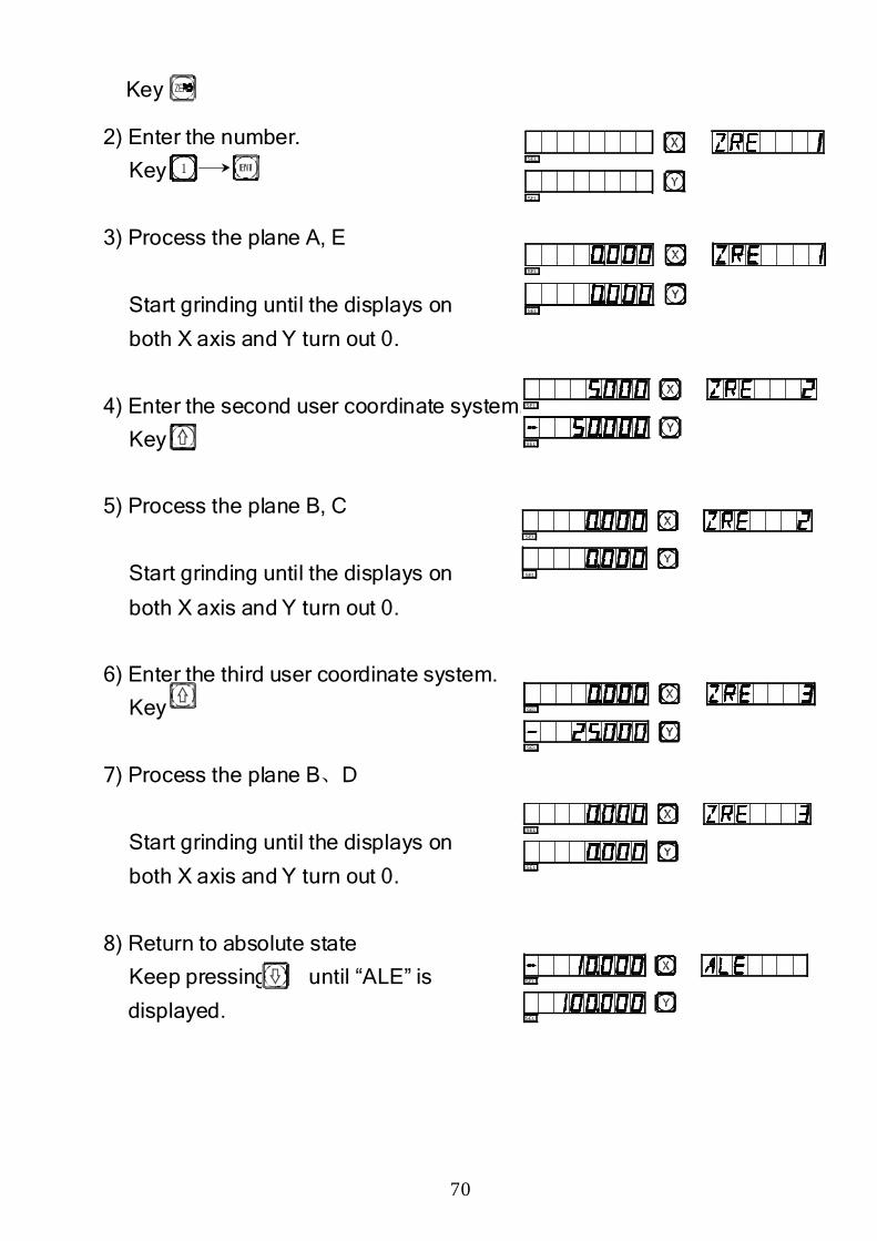
Key
2) Enter the number.
Key
3) Process the plane A, E
Start grinding until the displays on
both X axis and Y turn out 0.
4) Enter the second user coordinate system.
Key
5) Process the plane B, C
Start grinding until the displays on
both X axis and Y turn out 0.
6) Enter the third user coordinate system.
Key
7) Process the plane B、D
Start grinding until the displays on
both X axis and Y turn out 0.
8) Return to absolute state
Keep pressing until “ALE” is
displayed.
1
SEL
SEL
SEL
SEL
SEL
SEL
SEL
SEL
SEL
SEL
SEL
SEL
SEL
SEL

71
F.F.F.F.
PCD PCD PCD PCD Bolt Bolt Bolt Bolt Circle Circle Circle Circle FunctionFunctionFunctionFunction
(Equally(Equally(Equally(Equally ddddividing ividing ividing ividing hhhholesolesolesoles on bolt flange)on bolt flange)on bolt flange)on bolt flange)
72
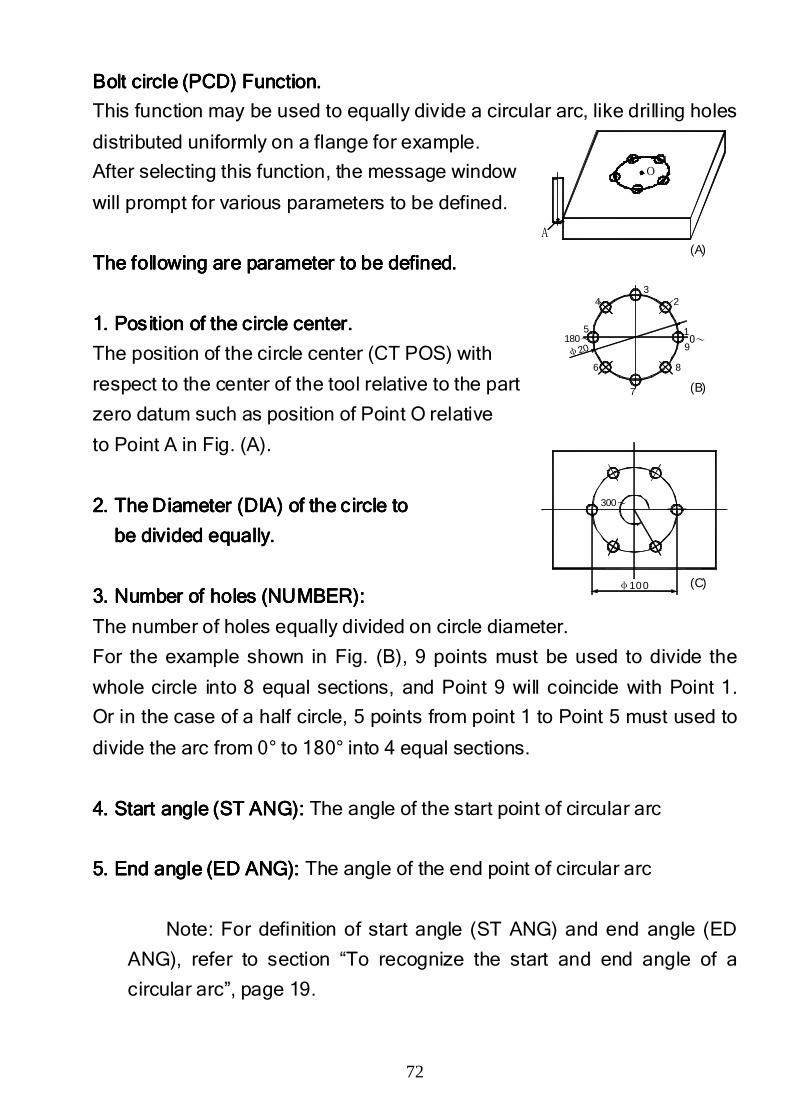
Bolt circle Bolt circle Bolt circle Bolt circle (PCD)(PCD)(PCD)(PCD) FunctionFunctionFunctionFunction....
This function may be used to equally divide a circular arc, like drilling holes
distributed uniformly on a flange for example.
After selecting this function, the message window
will prompt for various parameters to be defined.
The following are parameter to be defined.The following are parameter to be defined.The following are parameter to be defined.The following are parameter to be defined.
1. P1. P1. P1. Position oosition oosition oosition of the circle center.f the circle center.f the circle center.f the circle center.
The position of the circle center (CT POS) with
respect to the center of the tool relative to the part
zero datum such as position of Point O relative
to Point A in Fig. (A).
2.2.2.2. The Diameter The Diameter The Diameter The Diameter (DIA)(DIA)(DIA)(DIA) of the circle toof the circle toof the circle toof the circle to
be divided equally.be divided equally.be divided equally.be divided equally.
3. N3. N3. N3. Number of holesumber of holesumber of holesumber of holes (NUMBER):(NUMBER):(NUMBER):(NUMBER):
The number of holes equally divided on circle diameter.
For the example shown in Fig. (B), 9 points must be used to divide the
whole circle into 8 equal sections, and Point 9 will coincide with Point 1.
Or in the case of a half circle, 5 points from point 1 to Point 5 must used to
divide the arc from 0° to 180° into 4 equal sections.
4. S4. S4. S4. Start angle (ST ANG): tart angle (ST ANG): tart angle (ST ANG): tart angle (ST ANG): The angle of the start point of circular arc
5. E5. E5. E5. End angle (ED ANG):nd angle (ED ANG):nd angle (ED ANG):nd angle (ED ANG): The angle of the end point of circular arc
Note: For definition of start angle (ST ANG) and end angle (ED
ANG), refer to section “To recognize the start and end angle of a
circular arc”, page 19.
A
o
(A)
(B)
(C)
φ200~180~
1
23
4
5
6
7
8
9
300~
φ100
73
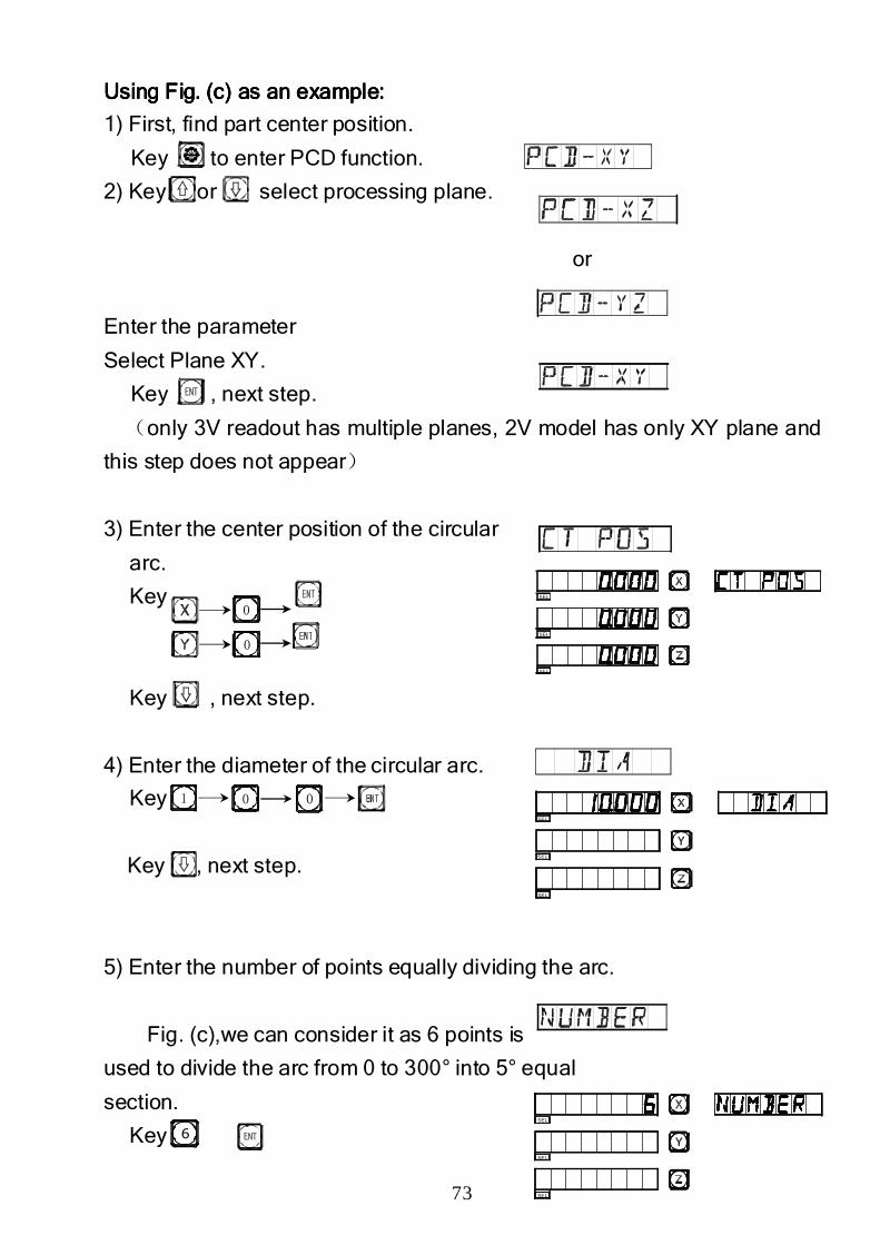
Using Using Using Using Fig. (c) as Fig. (c) as Fig. (c) as Fig. (c) as an an an an example:example:example:example:
1) First, find part center position.
Key to enter PCD function.
2) Key or select processing plane.
or
Enter the parameter
Select Plane XY.
Key , next step.
(only 3V readout has multiple planes, 2V model has only XY plane and
this step does not appear)
3) Enter the center position of the circular
arc.
Key
Key , next step.
4) Enter the diameter of the circular arc.
Key
Key , next step.
5) Enter the number of points equally dividing the arc.
Fig. (c),we can consider it as 6 points is
used to divide the arc from 0 to 300° into 5° equal
section.
Key
0
0
1 00
6
SEL
SEL
SEL
SEL
SEL
SEL
SEL
SEL
SEL
74
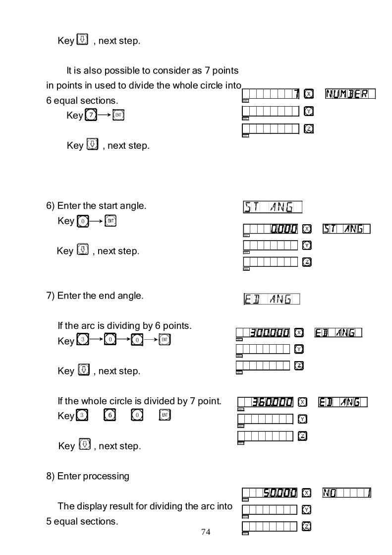
Key , next step.
It is also possible to consider as 7 points
in points in used to divide the whole circle into
6 equal sections.
Key
Key , next step.
6) Enter the start angle.
Key
Key , next step.
7) Enter the end angle.
If the arc is dividing by 6 points.
Key
Key , next step.
If the whole circle is divided by 7 point.
Key
Key , next step.
8) Enter processing
The display result for dividing the arc into
5 equal sections.
7
0
3
0
00
3 6
S EL
S EL
S EL
SEL
SEL
SEL
SEL
SEL
SEL
SEL
SEL
SEL
SEL
SEL
SEL
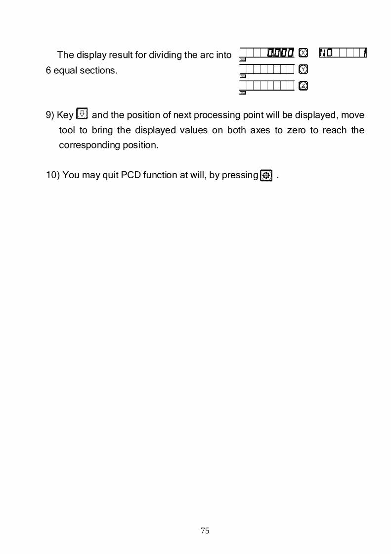
75
The display result for dividing the arc into
6 equal sections.
9) Key and the position of next processing point will be displayed, move
tool to bring the displayed values on both axes to zero to reach the
corresponding position.
10) You may quit PCD function at will, by pressing .
SEL
SEL
SEL

76
G.G.G.G.
Angular Surface ProcessingAngular Surface ProcessingAngular Surface ProcessingAngular Surface Processing
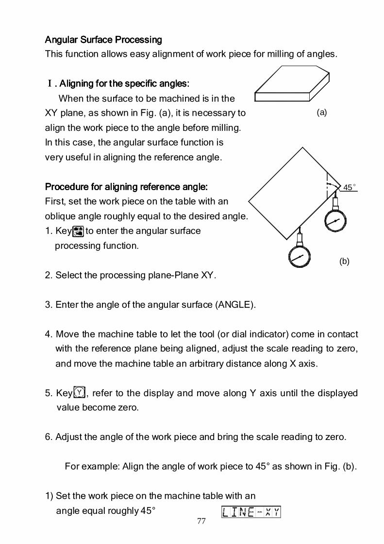
77
Angular Surface ProcessingAngular Surface ProcessingAngular Surface ProcessingAngular Surface Processing
This function allows easy alignment of work piece for milling of angles.
ⅠⅠⅠⅠ. Aligning for the . Aligning for the . Aligning for the . Aligning for the specific specific specific specific angleangleangleanglessss: : : :
When the surface to be machined is in the
XY plane, as shown in Fig. (a), it is necessary to
align the work piece to the angle before milling.
In this case, the angular surface function is
very useful in aligning the reference angle.
PPPProcedure rocedure rocedure rocedure for for for for aligning aligning aligning aligning reference reference reference reference angle:angle:angle:angle:
First, set the work piece on the table with an
oblique angle roughly equal to the desired angle.
1. Key, to enter the angular surface
processing function.
2. Select the processing plane-Plane XY.
3. Enter the angle of the angular surface (ANGLE).
4. Move the machine table to let the tool (or dial indicator) come in contact
with the reference plane being aligned, adjust the scale reading to zero,
and move the machine table an arbitrary distance along X axis.
5. Key , refer to the display and move along Y axis until the displayed
value become zero.
6. Adjust the angle of the work piece and bring the scale reading to zero.
For example: Align the angle of work piece to 45° as shown in Fig. (b).
1) Set the work piece on the machine table with an
angle equal roughly 45°
45°
(a)
(b)
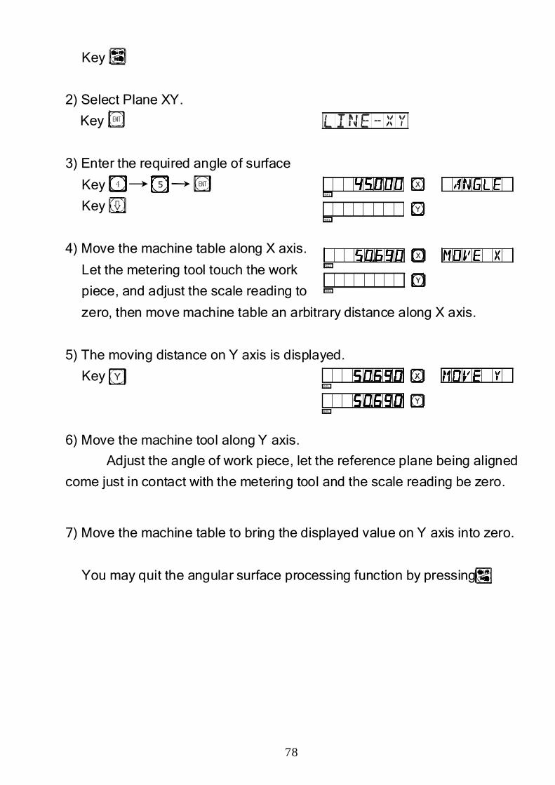
78
Key
2) Select Plane XY.
Key
3) Enter the required angle of surface
Key
Key
4) Move the machine table along X axis.
Let the metering tool touch the work
piece, and adjust the scale reading to
zero, then move machine table an arbitrary distance along X axis.
5) The moving distance on Y axis is displayed.
Key
6) Move the machine tool along Y axis.
Adjust the angle of work piece, let the reference plane being aligned
come just in contact with the metering tool and the scale reading be zero.
7) Move the machine table to bring the displayed value on Y axis into zero.
You may quit the angular surface processing function by pressing
54SEL
SEL
SEL
SEL
S EL
S EL
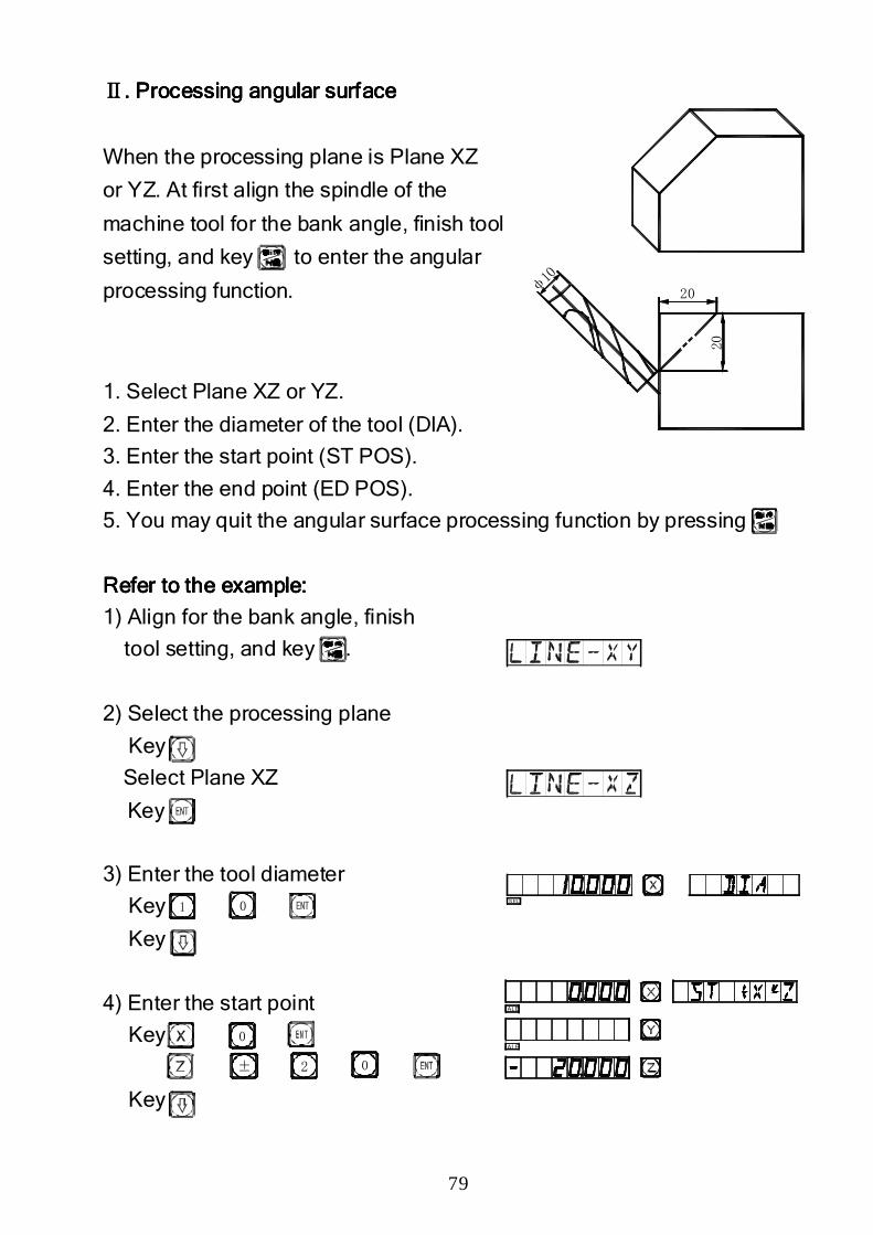
79
20
20
φ10
ⅡⅡⅡⅡ. Processing angular surface. Processing angular surface. Processing angular surface. Processing angular surface
When the processing plane is Plane XZ
or YZ. At first align the spindle of the
machine tool for the bank angle, finish tool
setting, and key to enter the angular
processing function.
1. Select Plane XZ or YZ.
2. Enter the diameter of the tool (DIA).
3. Enter the start point (ST POS).
4. Enter the end point (ED POS).
5. You may quit the angular surface processing function by pressing
Refer to the Refer to the Refer to the Refer to the example:example:example:example:
1) Align for the bank angle, finish
tool setting, and key .
2) Select the processing plane
Key
Select Plane XZ
Key
3) Enter the tool diameter
Key
Key
4) Enter the start point
Key
Key
1 0
0
± 2 0
S EL
ALE
ALE
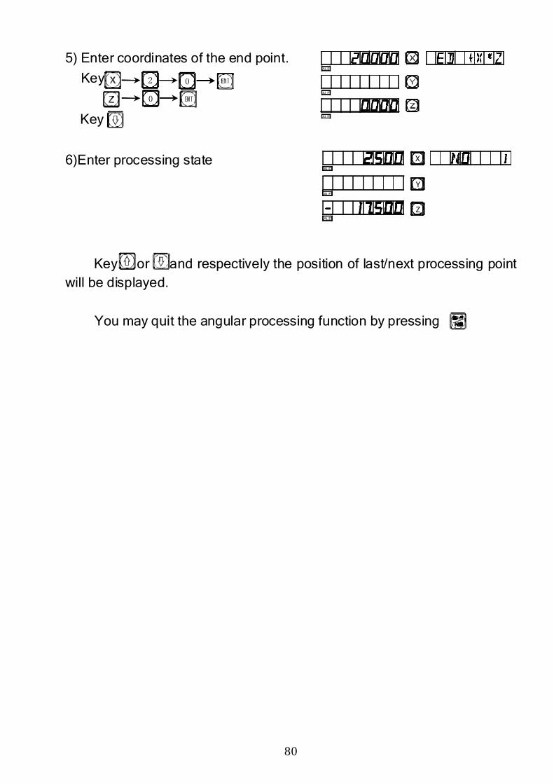
80
5) Enter coordinates of the end point.
Key
Key
6)Enter processing state
Key or and respectively the position of last/next processing point will be displayed.
You may quit the angular processing function by pressing
2
0
0ALE
ALE
ALE
Z
Y
X
ALE
ALE
ALE

81
H.H.H.H.
Calculator FunctionCalculator FunctionCalculator FunctionCalculator Function
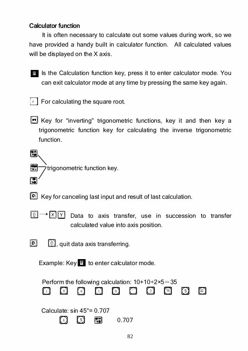
82
CalculatorCalculatorCalculatorCalculator functionfunctionfunctionfunction
It is often necessary to calculate out some values during work, so we
have provided a handy built in calculator function. All calculated values
will be displayed on the X axis.
Is the Calculation function key, press it to enter calculator mode. You
can exit calculator mode at any time by pressing the same key again.
For calculating the square root.
Key for “inverting” trigonometric functions, key it and then key a
trigonometric function key for calculating the inverse trigonometric
function.
trigonometric function key.
Key for canceling last input and result of last calculation.
Data to axis transfer, use in succession to transfer
calculated value into axis position.
, quit data axis transferring.
Example: Key to enter calculator mode.
Perform the following calculation: 10+10÷2×5=35
35
Calculate: sin 45°= 0.707
0.707
1 0 + 1 0 ¯ 2 ℅ 5 =
54
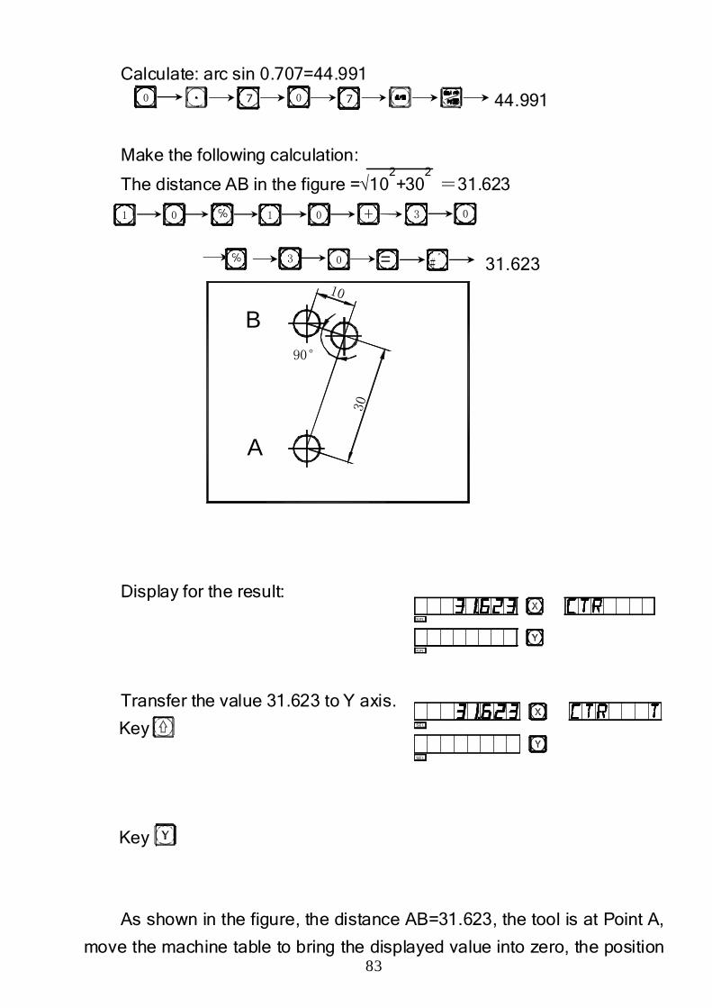
83
Calculate: arc sin 0.707=44.991
44.991
Make the following calculation:
The distance AB in the figure =√102+30
2 =31.623
31.623
Display for the result:
Transfer the value 31.623 to Y axis.
Key
Key
As shown in the figure, the distance AB=31.623, the tool is at Point A,
move the machine table to bring the displayed value into zero, the position
0 7 0 7
1 0 ℅ 1 0 + 3 0
℅ 3 0 = ﹟〞
SEL
SEL
S EL
S EL
B
A
90°30
10
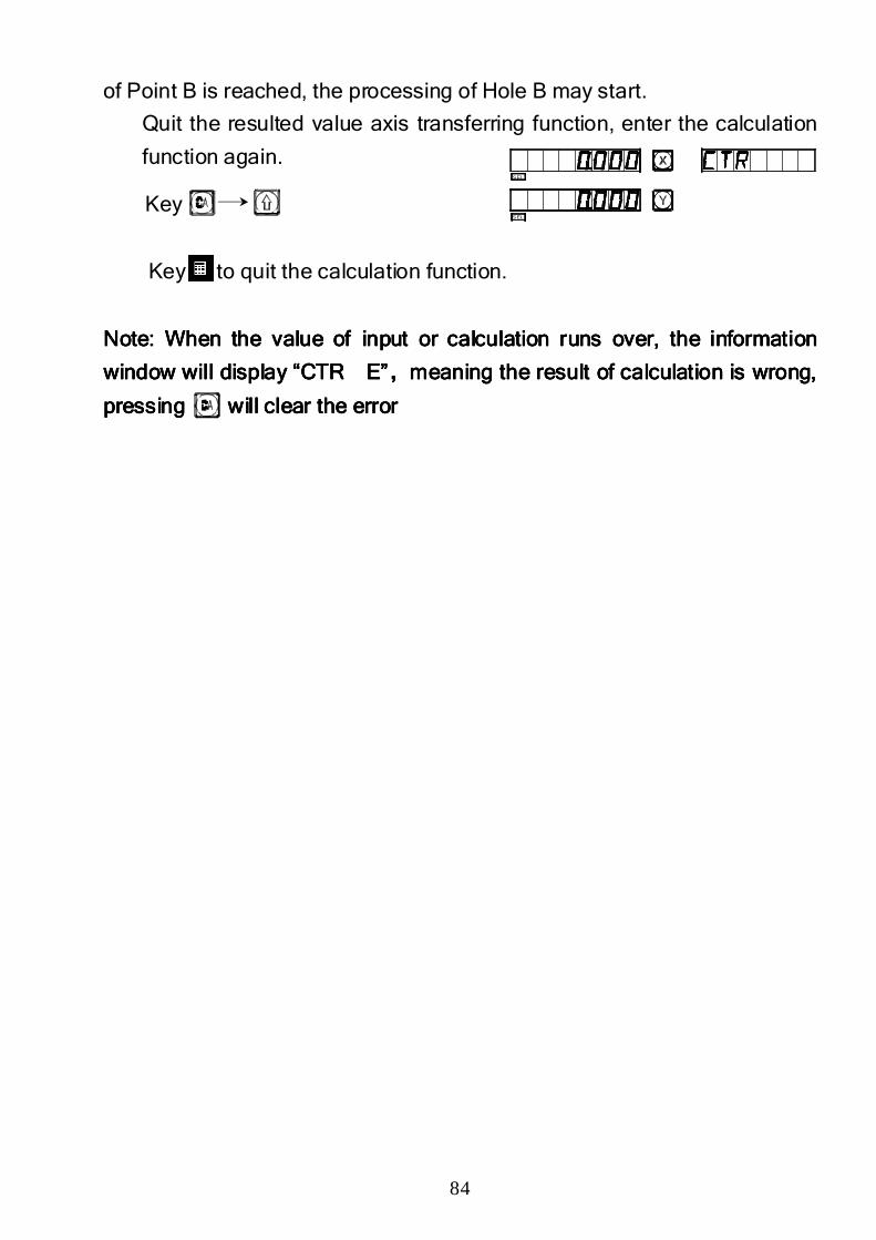
84
of Point B is reached, the processing of Hole B may start.
Quit the resulted value axis transferring function, enter the calculation
function again.
Key
Key to quit the calculation function.
NoteNoteNoteNote: When the value of input or calculation runs over, the information : When the value of input or calculation runs over, the information : When the value of input or calculation runs over, the information : When the value of input or calculation runs over, the information
window window window window will will will will displaydisplaydisplaydisplay “CTR E”“CTR E”“CTR E”“CTR E”,,,,meaningmeaningmeaningmeaning the result of calculation is wrong, the result of calculation is wrong, the result of calculation is wrong, the result of calculation is wrong,
presspresspresspressing ing ing ing will clear the errorwill clear the errorwill clear the errorwill clear the error
SEL
SEL

85
I.I.I.I.
Tool Diameter CompensationTool Diameter CompensationTool Diameter CompensationTool Diameter Compensation
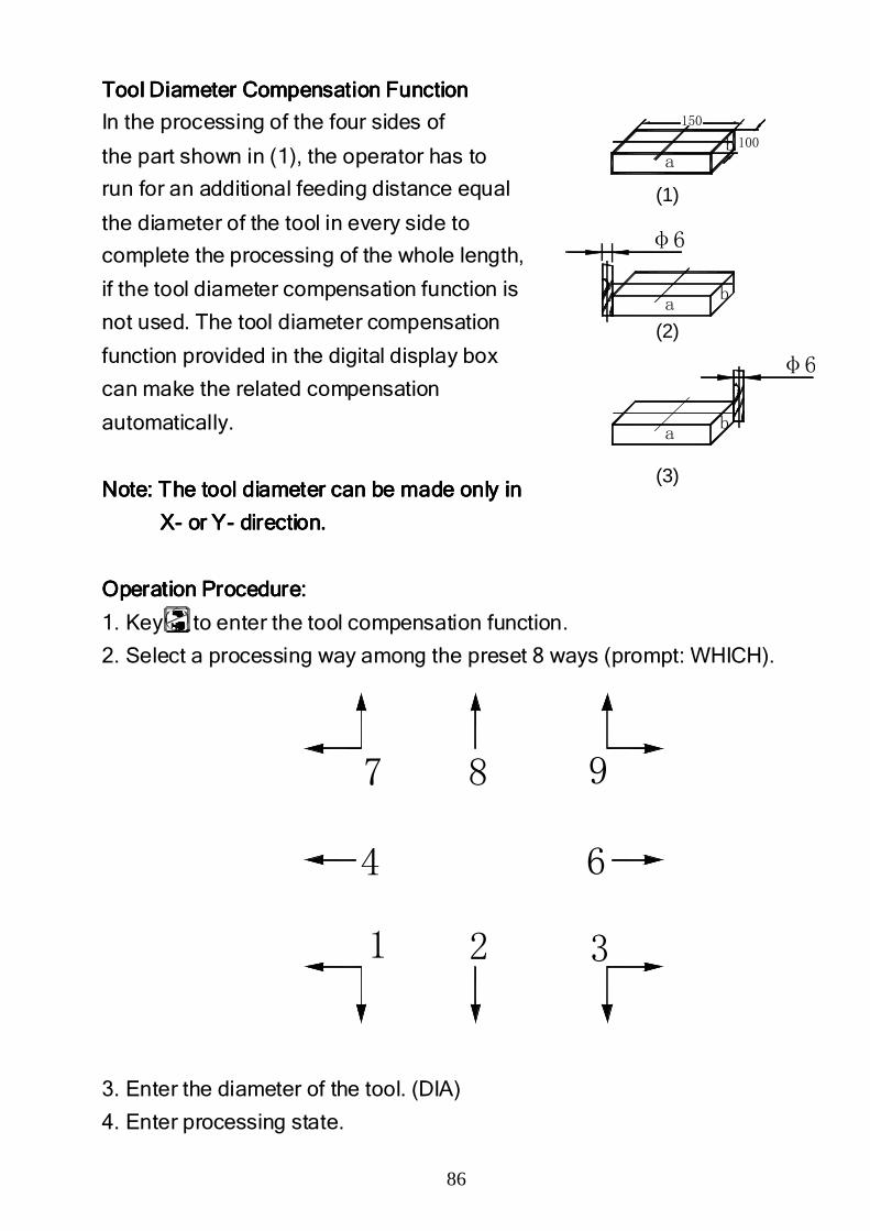
86
1
4
2 3
6
7 8 9
Tool Diameter Compensation FunctionTool Diameter Compensation FunctionTool Diameter Compensation FunctionTool Diameter Compensation Function
In the processing of the four sides of
the part shown in (1), the operator has to
run for an additional feeding distance equal
the diameter of the tool in every side to
complete the processing of the whole length,
if the tool diameter compensation function is
not used. The tool diameter compensation
function provided in the digital display box
can make the related compensation
automatically.
Note: The tool diameter can be made only inNote: The tool diameter can be made only inNote: The tool diameter can be made only inNote: The tool diameter can be made only in
XXXX---- or Yor Yor Yor Y---- direction.direction.direction.direction.
Operation Procedure:Operation Procedure:Operation Procedure:Operation Procedure:
1. Key to enter the tool compensation function.
2. Select a processing way among the preset 8 ways (prompt: WHICH).
3. Enter the diameter of the tool. (DIA)
4. Enter processing state.
ab
ab
150
100
φ6
φ6
ab
(1)
(2)
(3)
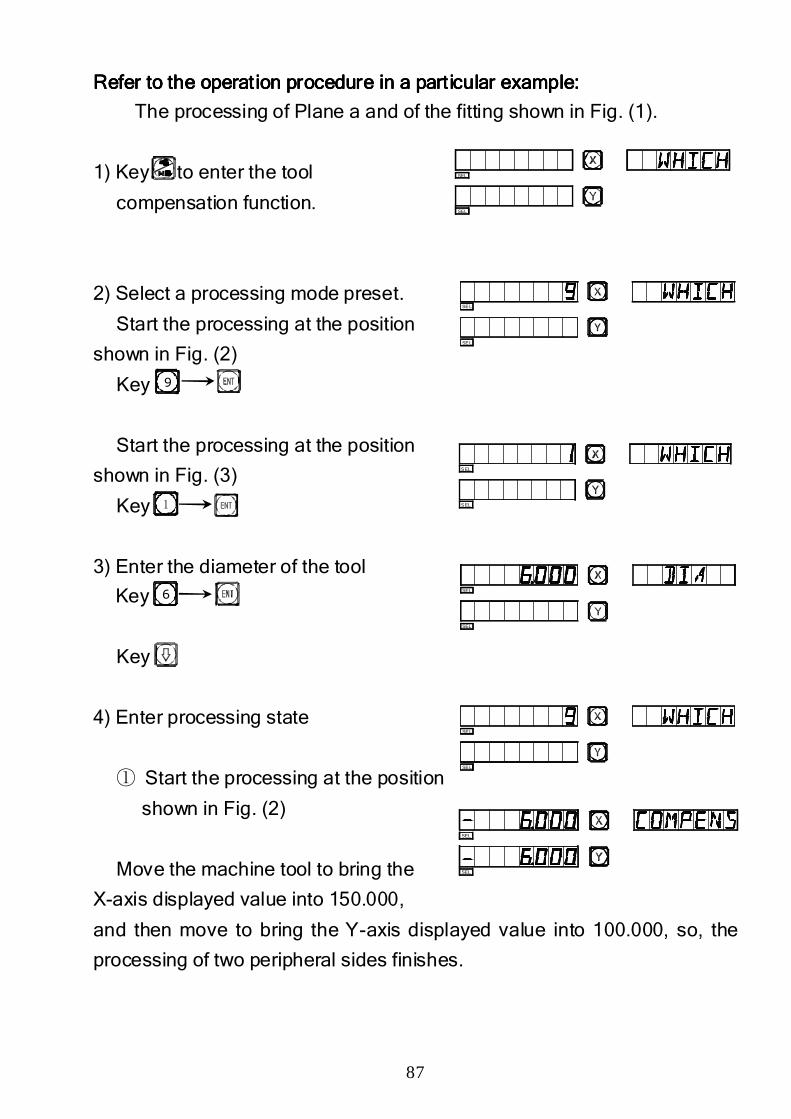
87
Refer to the operation procedure in a particular example:Refer to the operation procedure in a particular example:Refer to the operation procedure in a particular example:Refer to the operation procedure in a particular example:
The processing of Plane a and of the fitting shown in Fig. (1).
1) Key to enter the tool
compensation function.
2) Select a processing mode preset.
Start the processing at the position
shown in Fig. (2)
Key
Start the processing at the position
shown in Fig. (3)
Key
3) Enter the diameter of the tool
Key
Key
4) Enter processing state
① Start the processing at the position
shown in Fig. (2)
Move the machine tool to bring the
X-axis displayed value into 150.000,
and then move to bring the Y-axis displayed value into 100.000, so, the
processing of two peripheral sides finishes.
9
1
6
SEL
SEL
SEL
SEL
SEL
SEL
SEL
SEL
SEL
SEL
SEL
SEL
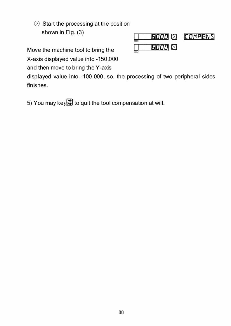
88
② Start the processing at the position
shown in Fig. (3)
Move the machine tool to bring the
X-axis displayed value into -150.000
and then move to bring the Y-axis
displayed value into -100.000, so, the processing of two peripheral sides
finishes.
5) You may key to quit the tool compensation at will.
SEL
SEL

89
J.J.J.J.
200 Tool Storeroom200 Tool Storeroom200 Tool Storeroom200 Tool Storeroom
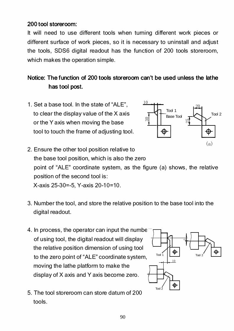
90
200 tool storeroom:200 tool storeroom:200 tool storeroom:200 tool storeroom:
It will need to use different tools when turning different work pieces or
different surface of work pieces, so it is necessary to uninstall and adjust
the tools, SDS6 digital readout has the function of 200 tools storeroom,
which makes the operation simple.
Notice: The function of 200 tools storeroom can’t be used Notice: The function of 200 tools storeroom can’t be used Notice: The function of 200 tools storeroom can’t be used Notice: The function of 200 tools storeroom can’t be used unless the unless the unless the unless the lathe lathe lathe lathe
has has has has tool posttool posttool posttool post. . . .
1. Set a base tool. In the state of “ALE”,
to clear the display value of the X axis
or the Y axis when moving the base
tool to touch the frame of adjusting tool.
2. Ensure the other tool position relative to
the base tool position, which is also the zero
point of “ALE” coordinate system, as the figure (a) shows, the relative
position of the second tool is:
X-axis 25-30=-5, Y-axis 20-10=10.
3. Number the tool, and store the relative position to the base tool into the
digital readout.
4. In process, the operator can input the numbers
of using tool, the digital readout will display
the relative position dimension of using tool
to the zero point of “ALE” coordinate system,
moving the lathe platform to make the
display of X axis and Y axis become zero.
5. The tool storeroom can store datum of 200
tools.
Base Tool Tool 2Tool 1
(a)
10
30
25
20
Tool 1 Tool 2
Tool 2
10
5
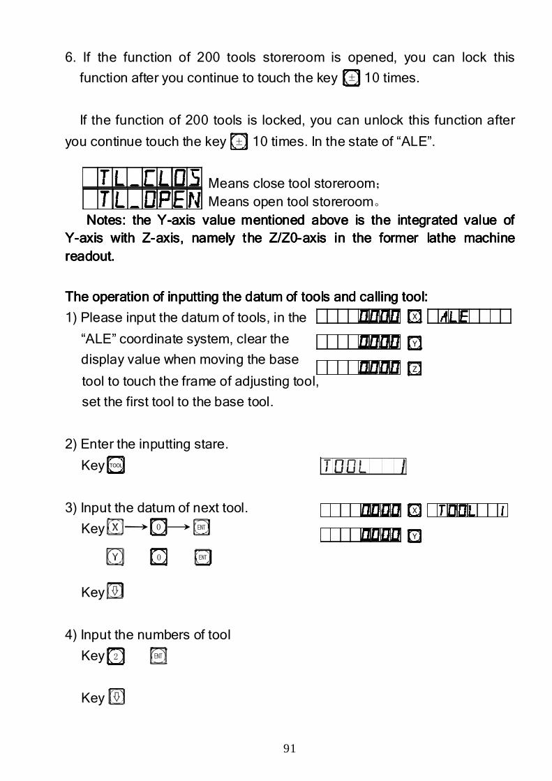
91
6. If the function of 200 tools storeroom is opened, you can lock this
function after you continue to touch the key 10 times.
If the function of 200 tools is locked, you can unlock this function after
you continue touch the key 10 times. In the state of “ALE”.
Means close tool storeroom; Means open tool storeroom。 Notes: the YNotes: the YNotes: the YNotes: the Y----axis value mentioned above is the integratedaxis value mentioned above is the integratedaxis value mentioned above is the integratedaxis value mentioned above is the integrated value of value of value of value of
YYYY----axis with Zaxis with Zaxis with Zaxis with Z----axis, namely the Z/Z0axis, namely the Z/Z0axis, namely the Z/Z0axis, namely the Z/Z0----axis in the former lathe machine axis in the former lathe machine axis in the former lathe machine axis in the former lathe machine readout.readout.readout.readout.
The operation of inputting the datum of tools and calling tool:The operation of inputting the datum of tools and calling tool:The operation of inputting the datum of tools and calling tool:The operation of inputting the datum of tools and calling tool:
1) Please input the datum of tools, in the
“ALE” coordinate system, clear the
display value when moving the base
tool to touch the frame of adjusting tool,
set the first tool to the base tool.
2) Enter the inputting stare.
Key
3) Input the datum of next tool.
Key
Key
4) Input the numbers of tool
Key
Key
±
±
0
0
2
Z
Y
X
TOOL
Y
X
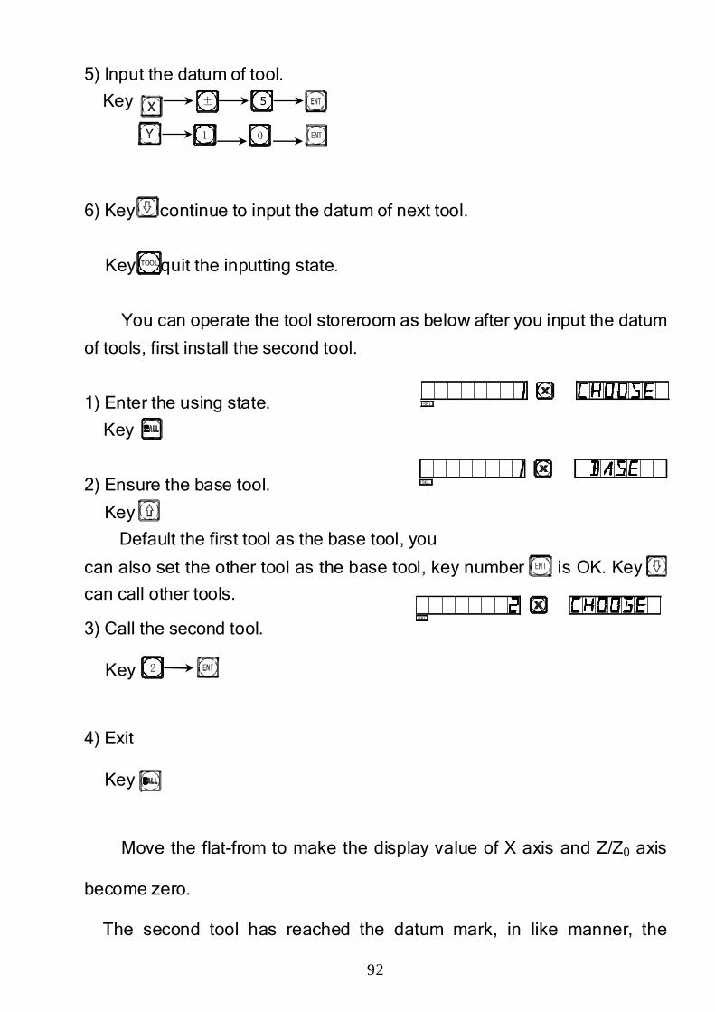
92
5) Input the datum of tool.
Key
6) Key continue to input the datum of next tool.
Key quit the inputting state.
You can operate the tool storeroom as below after you input the datum
of tools, first install the second tool.
1) Enter the using state.
Key
2) Ensure the base tool.
Key
Default the first tool as the base tool, you
can also set the other tool as the base tool, key number is OK. Key
can call other tools.
3) Call the second tool.
Key
4) Exit
Key
Move the flat-from to make the display value of X axis and Z/Z0 axis
become zero.
The second tool has reached the datum mark, in like manner, the
± 5
01
2
SEL
SEL
SEL
TOOL

93
operator can input and call 200 tools.
Notice: You can clear the display value to zero in “ALE” coordinaNotice: You can clear the display value to zero in “ALE” coordinaNotice: You can clear the display value to zero in “ALE” coordinaNotice: You can clear the display value to zero in “ALE” coordinate system te system te system te system
only when using the base tool, you can clear the display value to only when using the base tool, you can clear the display value to only when using the base tool, you can clear the display value to only when using the base tool, you can clear the display value to
zero in “INC” coordinate system when using other tools.zero in “INC” coordinate system when using other tools.zero in “INC” coordinate system when using other tools.zero in “INC” coordinate system when using other tools.

94
K.K.K.K.
TaperTaperTaperTaper measure Functionmeasure Functionmeasure Functionmeasure Function
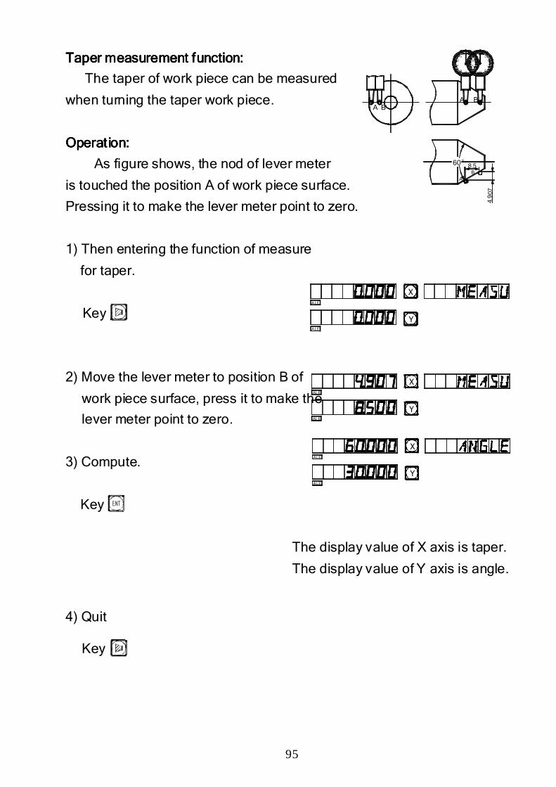
95
TTTTaper measurement faper measurement faper measurement faper measurement function: unction: unction: unction:
The taper of work piece can be measured
when turning the taper work piece.
Operation:Operation:Operation:Operation:
As figure shows, the nod of lever meter
is touched the position A of work piece surface.
Pressing it to make the lever meter point to zero.
1) Then entering the function of measure
for taper.
Key
2) Move the lever meter to position B of
work piece surface, press it to make the
lever meter point to zero.
3) Compute.
Key
The display value of X axis is taper.
The display value of Y axis is angle.
4) Quit
Key
60°
A BA B
090
80
70
6050
40
302 0
10
302 0
70
504060
1090
80
0
8.5
4.9 0
7
AB
Y
X
ALE
ALE
Y
X
ALE
ALE
Y
X
ALE
ALE
96
L.L.L.L.
EDM Matching Output FunctionEDM Matching Output FunctionEDM Matching Output FunctionEDM Matching Output Function
((((3V3V3V3V----EDMEDMEDMEDM onlyonlyonlyonly))))
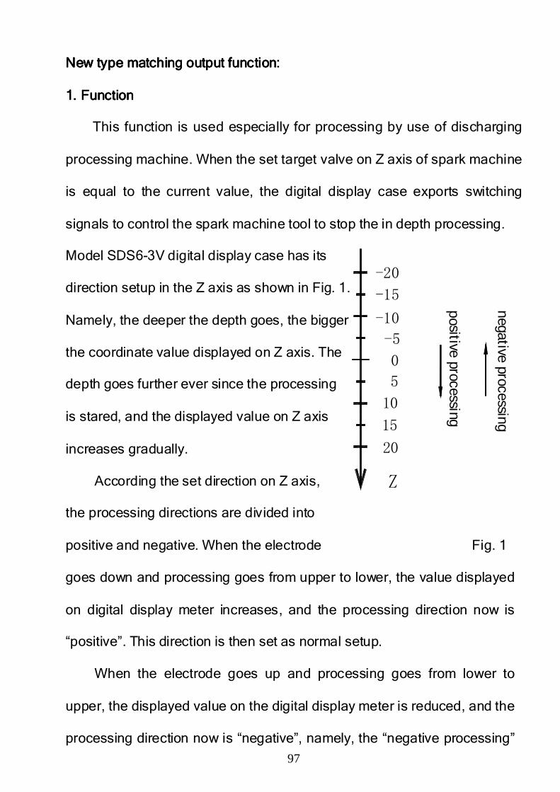
97
po sitive processing
10
Z
20
15
-20
-15
-10
-5
5
0
negative processingNew type matching output function:New type matching output function:New type matching output function:New type matching output function:
1. Function1. Function1. Function1. Function
This function is used especially for processing by use of discharging
processing machine. When the set target valve on Z axis of spark machine
is equal to the current value, the digital display case exports switching
signals to control the spark machine tool to stop the in depth processing.
Model SDS6-3V digital display case has its
direction setup in the Z axis as shown in Fig. 1.
Namely, the deeper the depth goes, the bigger
the coordinate value displayed on Z axis. The
depth goes further ever since the processing
is stared, and the displayed value on Z axis
increases gradually.
According the set direction on Z axis,
the processing directions are divided into
positive and negative. When the electrode Fig. 1
goes down and processing goes from upper to lower, the value displayed
on digital display meter increases, and the processing direction now is
“positive”. This direction is then set as normal setup.
When the electrode goes up and processing goes from lower to
upper, the displayed value on the digital display meter is reduced, and the
processing direction now is “negative”, namely, the “negative processing”
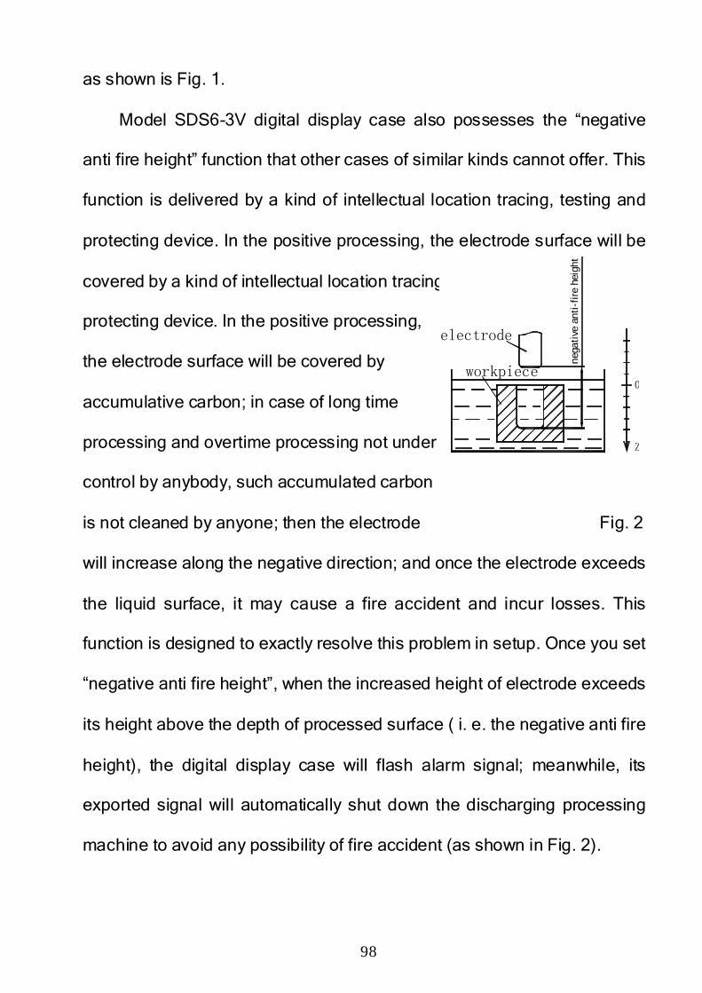
98
as shown is Fig. 1.
Model SDS6-3V digital display case also possesses the “negative
anti fire height” function that other cases of similar kinds cannot offer. This
function is delivered by a kind of intellectual location tracing, testing and
protecting device. In the positive processing, the electrode surface will be
covered by a kind of intellectual location tracing, testing and
protecting device. In the positive processing,
the electrode surface will be covered by
accumulative carbon; in case of long time
processing and overtime processing not under
control by anybody, such accumulated carbon
is not cleaned by anyone; then the electrode Fig. 2
will increase along the negative direction; and once the electrode exceeds
the liquid surface, it may cause a fire accident and incur losses. This
function is designed to exactly resolve this problem in setup. Once you set
“negative anti fire height”, when the increased height of electrode exceeds
its height above the depth of processed surface ( i. e. the negative anti fire
height), the digital display case will flash alarm signal; meanwhile, its
exported signal will automatically shut down the discharging processing
machine to avoid any possibility of fire accident (as shown in Fig. 2).
workpiece
electrode
Z
0
nega
tive
ant
i-fi
re h
eigh
t
99
2. Concrete operating methods:2. Concrete operating methods:2. Concrete operating methods:2. Concrete operating methods:
See the concrete processing examples 1, 2 and 3.
1) Before processing, first set the parameters “negative anti-fir height”,
“exit mode”, and “processing direction”.
2) First, move the main axis electrode on Z axis to make it touch work piece
datum. Reset or enter a figure.
3) Press button, enter your desired depth value (to be displayed on X
axis to). Such as 10. Then press button to confirm the input value.
Afterwards, press the button to exit from “Depth” status. At the same
time, enter the “EDM” status to conduct processing.
4) X-axis will display “target value of personal location”
Y-axis will display “value of depth reached”. Note: Values on Y-axis
means the depths reached on the work piece by processing.
Z-axis will display “real time value of personal location”. Note: Values on
Z-axis mean the values of locations of main axis electrode on Z-axis.
5) Start processing. The displayed value on Z-axis gradually gets close to
the target value. The displayed value on Y-axis also gets close to the
target value. If the electrode is repeated raised and lowered at this time,
the displayed value on Z-axis will change accordingly. But the displayed
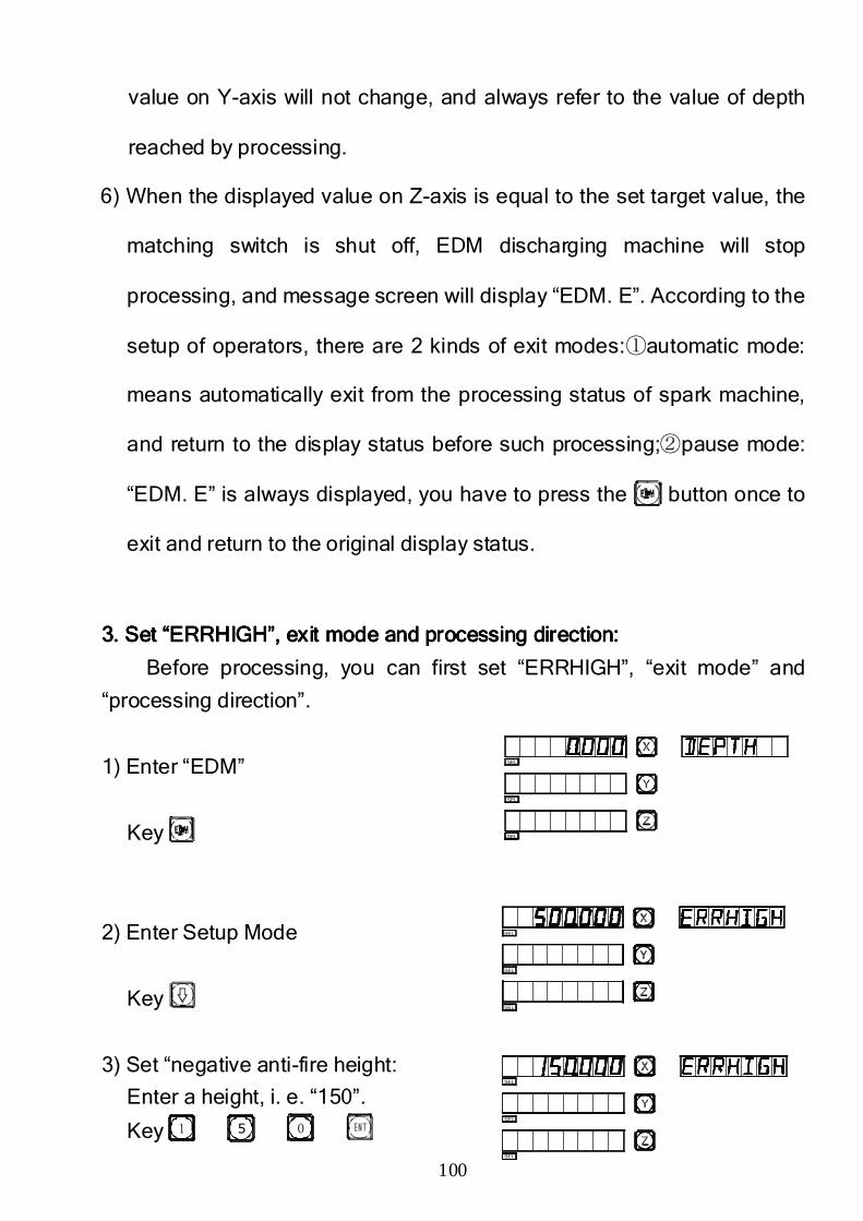
100
value on Y-axis will not change, and always refer to the value of depth
reached by processing.
6) When the displayed value on Z-axis is equal to the set target value, the
matching switch is shut off, EDM discharging machine will stop
processing, and message screen will display “EDM. E”. According to the
setup of operators, there are 2 kinds of exit modes:①automatic mode:
means automatically exit from the processing status of spark machine,
and return to the display status before such processing;②pause mode:
“EDM. E” is always displayed, you have to press the button once to
exit and return to the original display status.
3. Set “ERRHIGH”, exit mode and processing direction3. Set “ERRHIGH”, exit mode and processing direction3. Set “ERRHIGH”, exit mode and processing direction3. Set “ERRHIGH”, exit mode and processing direction::::
Before processing, you can first set “ERRHIGH”, “exit mode” and
“processing direction”.
1) Enter “EDM”
Key
2) Enter Setup Mode
Key
3) Set “negative anti-fire height:
Enter a height, i. e. “150”.
Key 51 0
SEL
SEL
SEL
SEL
SEL
SEL
SEL
SEL
SEL
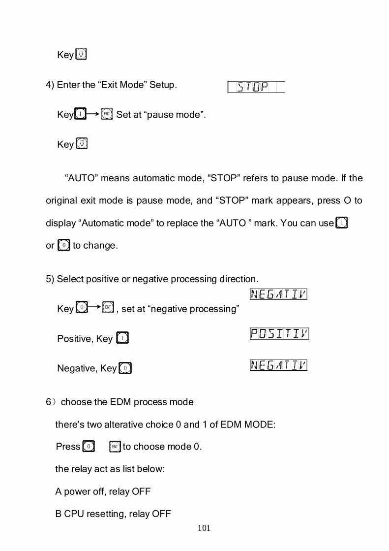
101
Key
4) Enter the “Exit Mode” Setup.
Key Set at “pause mode”.
Key
“AUTO” means automatic mode, “STOP” refers to pause mode. If the
original exit mode is pause mode, and “STOP” mark appears, press O to
display “Automatic mode” to replace the “AUTO ” mark. You can use
or to change.
5) Select positive or negative processing direction.
Key , set at “negative processing”
Positive, Key
Negative, Key
6)choose the EDM process mode
there’s two alterative choice 0 and 1 of EDM MODE:
Press to choose mode 0.
the relay act as list below:
A power off, relay OFF
B CPU resetting, relay OFF
1
0
1
0
0
1
0
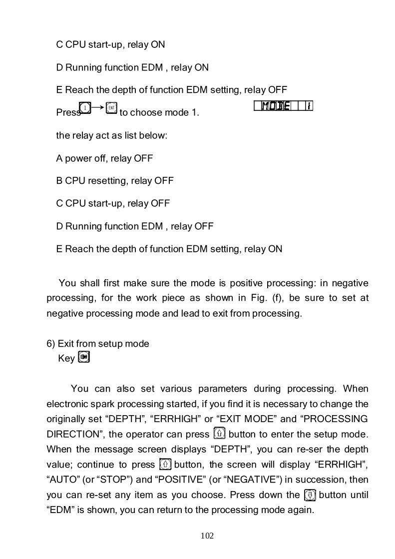
102
C CPU start-up, relay ON
D Running function EDM , relay ON
E Reach the depth of function EDM setting, relay OFF
Press to choose mode 1.
the relay act as list below:
A power off, relay OFF
B CPU resetting, relay OFF
C CPU start-up, relay OFF
D Running function EDM , relay OFF
E Reach the depth of function EDM setting, relay ON
You shall first make sure the mode is positive processing: in negative
processing, for the work piece as shown in Fig. (f), be sure to set at
negative processing mode and lead to exit from processing.
6) Exit from setup mode
Key
You can also set various parameters during processing. When
electronic spark processing started, if you find it is necessary to change the
originally set “DEPTH”, “ERRHIGH” or “EXIT MODE” and “PROCESSING
DIRECTION”, the operator can press button to enter the setup mode.
When the message screen displays “DEPTH”, you can re-ser the depth
value; continue to press button, the screen will display “ERRHIGH”,
“AUTO” (or “STOP”) and “POSITIVE” (or “NEGATIVE”) in succession, then
you can re-set any item as you choose. Press down the button until
“EDM” is shown, you can return to the processing mode again.
1
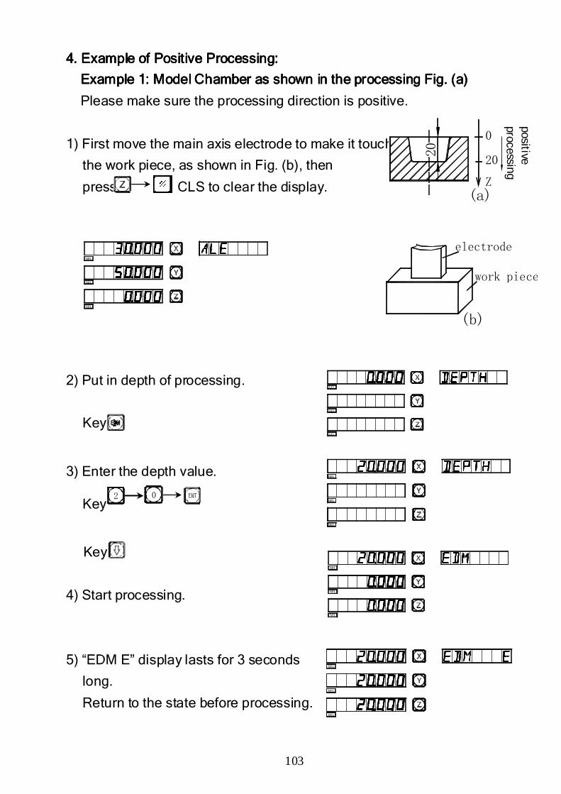
103
4. Example of Positive Processing:4. Example of Positive Processing:4. Example of Positive Processing:4. Example of Positive Processing:
Example 1: Model Chamber as shown in the processing Fig. (a)Example 1: Model Chamber as shown in the processing Fig. (a)Example 1: Model Chamber as shown in the processing Fig. (a)Example 1: Model Chamber as shown in the processing Fig. (a)
Please make sure the processing direction is positive.
1) First move the main axis electrode to make it touch
the work piece, as shown in Fig. (b), then
press CLS to clear the display.
2) Put in depth of processing.
Key
3) Enter the depth value.
Key
Key
4) Start processing.
5) “EDM E” display lasts for 3 seconds
long.
Return to the state before processing.
02
SEL
SEL
SEL
SEL
SEL
SEL
SEL
SEL
SEL
SEL
SEL
SEL
SEL
SEL
SEL
(a)Z
20
0
positive proce ssing
20
(b)
electrode
work piece
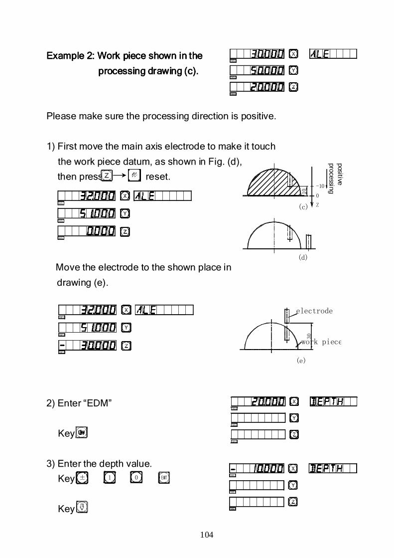
104
SEL
SEL
SEL
Example 2: Work piece shown in theExample 2: Work piece shown in theExample 2: Work piece shown in theExample 2: Work piece shown in the
processing drawing (c).processing drawing (c).processing drawing (c).processing drawing (c).
Please make sure the processing direction is positive.
1) First move the main axis electrode to make it touch
the work piece datum, as shown in Fig. (d),
then press reset.
Move the electrode to the shown place in
drawing (e).
2) Enter “EDM”
Key
3) Enter the depth value.
Key
Key
± 1 0
SEL
SEL
SEL
SEL
SEL
SEL
(d)
-10
(c) Z
0
positive processing
10
S EL
S EL
S EL
SEL
SEL
SEL
(e)
electrode
work piece
30
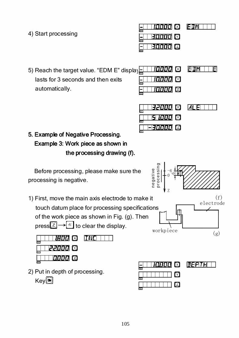
105
0-6
Z
(g)
(f)
ne
ga
tive
p
roc
es
sin
g
electrode
workpiece
6
4) Start processing
5) Reach the target value. “EDM E” display
lasts for 3 seconds and then exits
automatically.
5. Example of Negative Processing.5. Example of Negative Processing.5. Example of Negative Processing.5. Example of Negative Processing.
Example 3: Work piece as shown inExample 3: Work piece as shown inExample 3: Work piece as shown inExample 3: Work piece as shown in
the processing drawing (f).the processing drawing (f).the processing drawing (f).the processing drawing (f).
Before processing, please make sure the
processing is negative.
1) First, move the main axis electrode to make it
touch datum place for processing specifications
of the work piece as shown in Fig. (g). Then
press to clear the display.
2) Put in depth of processing.
Key
SEL
SEL
SEL
SEL
SEL
SEL
SEL
SEL
SEL
SEL
SEL
SEL
SEL
SEL
SEL
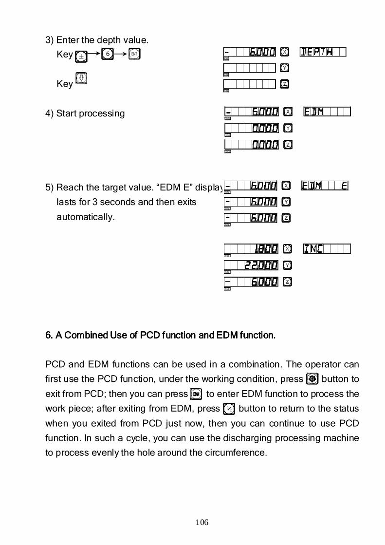
106
3) Enter the depth value.
Key
Key
4) Start processing
5) Reach the target value. “EDM E” display
lasts for 3 seconds and then exits
automatically.
6. A Combined Use of PCD function and EDM function.6. A Combined Use of PCD function and EDM function.6. A Combined Use of PCD function and EDM function.6. A Combined Use of PCD function and EDM function.
PCD and EDM functions can be used in a combination. The operator can
first use the PCD function, under the working condition, press button to
exit from PCD; then you can press to enter EDM function to process the
work piece; after exiting from EDM, press button to return to the status
when you exited from PCD just now, then you can continue to use PCD
function. In such a cycle, you can use the discharging processing machine
to process evenly the hole around the circumference.
± 6
12
SEL
SEL
SEL
SEL
SEL
SEL
SEL
SEL
SEL
SEL
SEL
SEL
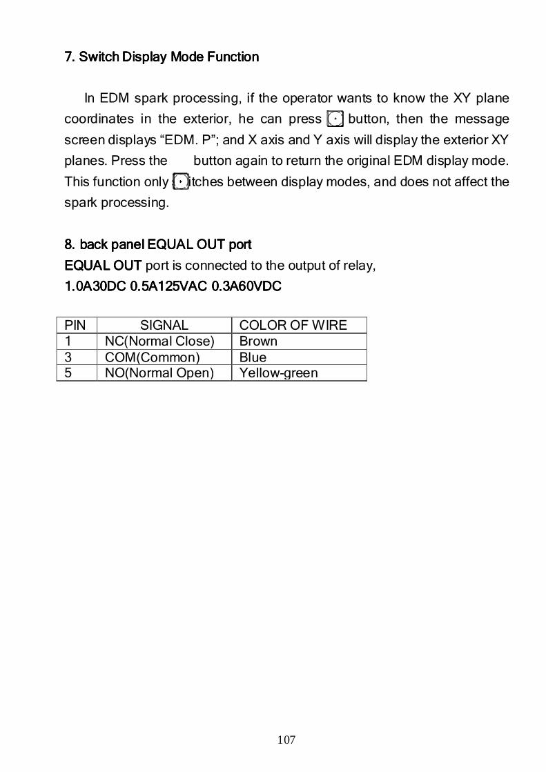
107
7. Switch Display Mode Function7. Switch Display Mode Function7. Switch Display Mode Function7. Switch Display Mode Function
In EDM spark processing, if the operator wants to know the XY plane
coordinates in the exterior, he can press button, then the message
screen displays “EDM. P”; and X axis and Y axis will display the exterior XY
planes. Press the button again to return the original EDM display mode.
This function only switches between display modes, and does not affect the
spark processing.
8. back panel EQUAL OUT port8. back panel EQUAL OUT port8. back panel EQUAL OUT port8. back panel EQUAL OUT port
EQUAL OUTEQUAL OUTEQUAL OUTEQUAL OUT port is connected to the output of relay,
1.0A30DC 0.5A125VAC 0.3A60VDC1.0A30DC 0.5A125VAC 0.3A60VDC1.0A30DC 0.5A125VAC 0.3A60VDC1.0A30DC 0.5A125VAC 0.3A60VDC
PIN SIGNAL COLOR OF WIRE 1 NC(Normal Close) Brown 3 COM(Common) Blue 5 NO(Normal Open) Yellow-green

108
M.M.M.M.
Digital FilterDigital FilterDigital FilterDigital Filter FunctionFunctionFunctionFunction
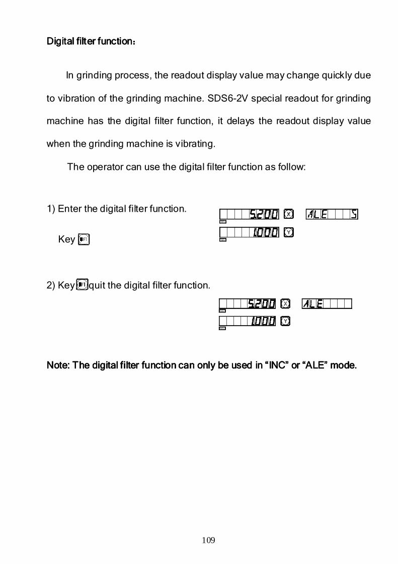
109
Digital filter functionDigital filter functionDigital filter functionDigital filter function::::
In grinding process, the readout display value may change quickly due
to vibration of the grinding machine. SDS6-2V special readout for grinding
machine has the digital filter function, it delays the readout display value
when the grinding machine is vibrating.
The operator can use the digital filter function as follow:
1) Enter the digital filter function.
Key
2) Key quit the digital filter function.
Note: The digital filter function can only be used in “INC” or “ALE” mode.Note: The digital filter function can only be used in “INC” or “ALE” mode.Note: The digital filter function can only be used in “INC” or “ALE” mode.Note: The digital filter function can only be used in “INC” or “ALE” mode.
SEL
SEL
SEL
SEL
110
N.N.N.N.
Vertical Slope MillingVertical Slope MillingVertical Slope MillingVertical Slope Milling
““““N3N3N3N3”””” FunctionFunctionFunctionFunction
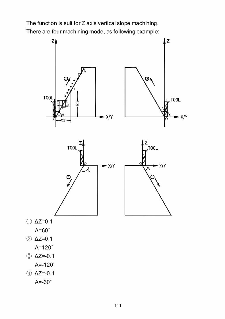
111
The function is suit for Z axis vertical slope machining.
There are four machining mode, as following example:
① ∆Z=0.1
A=60 ̊
② ∆Z=0.1
A=120˚
③ ∆Z=-0.1
A=-120˚
④ ∆Z=-0.1
A=-60˚
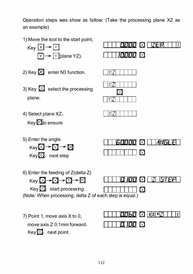
112
Operation steps was show as fallow: (Take the processing plane XZ as
an example)
1) Move the tool to the start point,
Key
(plane YZ).
2) Key ,enter N3 function.
3) Key ,select the processing
plane.
4) Select plane XZ,
Key to ensure
5) Enter the angle.
Key
Key ,next step
6) Enter the feeding of Z(delta Z)
Key
Key ,start processing. (Note: When processing, delta Z of each step is equal.)
7) Point 1, move axis X to 0,
move axis Z 0.1mm forward.
Key ,next point.
N3
tg
6 0
0
X
Y
X
Y
X
Y
X
Y
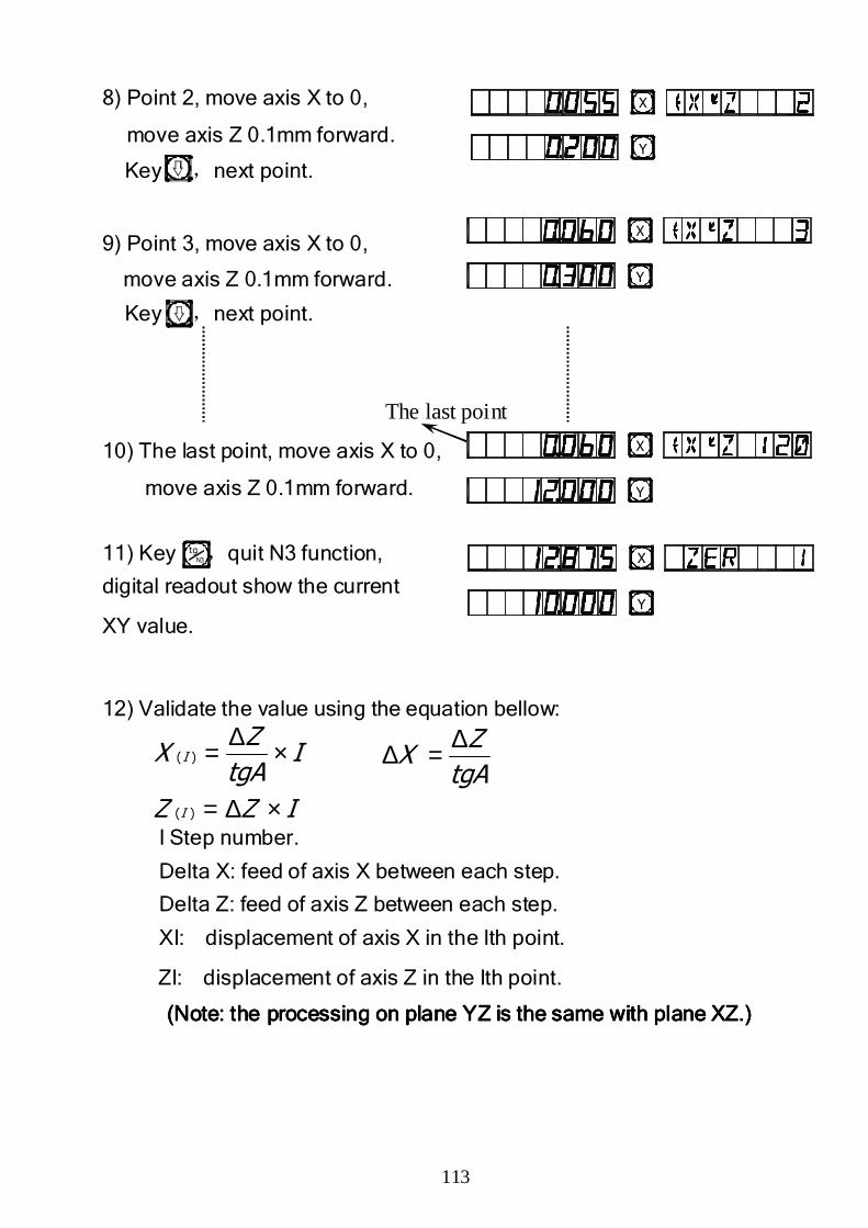
113
8) Point 2, move axis X to 0,
move axis Z 0.1mm forward.
Key ,next point.
9) Point 3, move axis X to 0,
move axis Z 0.1mm forward.
Key ,next point.
10) The last point, move axis X to 0,
move axis Z 0.1mm forward.
11) Key ,quit N3 function,
digital readout show the current
XY value.
12) Validate the value using the equation bellow:
I Step number.
Delta X: feed of axis X between each step.
Delta Z: feed of axis Z between each step.
XI: displacement of axis X in the Ith point.
ZI: displacement of axis Z in the Ith point.
(Note: the processing on plane YZ is the same with plane XZ.)(Note: the processing on plane YZ is the same with plane XZ.)(Note: the processing on plane YZ is the same with plane XZ.)(Note: the processing on plane YZ is the same with plane XZ.)
N3
tg
ItgA
ZX I ×∆=)(
IZZ I ×∆=)(
The last point
X
Y
X
Y
X
Y
X
Y
tgA
ZX
∆=∆
114
O.O.O.O.
RRRRectangular ectangular ectangular ectangular pocket milling.pocket milling.pocket milling.pocket milling.
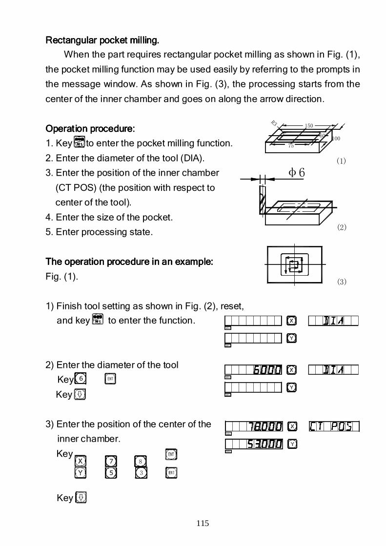
115
(3)
(2)
60
75
R3150
(1)
100
φ6
RRRRectangular ectangular ectangular ectangular pocket milling.pocket milling.pocket milling.pocket milling.
When the part requires rectangular pocket milling as shown in Fig. (1),
the pocket milling function may be used easily by referring to the prompts in
the message window. As shown in Fig. (3), the processing starts from the
center of the inner chamber and goes on along the arrow direction.
Operation procedure:Operation procedure:Operation procedure:Operation procedure:
1. Key to enter the pocket milling function.
2. Enter the diameter of the tool (DIA).
3. Enter the position of the inner chamber
(CT POS) (the position with respect to
center of the tool).
4. Enter the size of the pocket.
5. Enter processing state.
The operation procedure in an example:The operation procedure in an example:The operation procedure in an example:The operation procedure in an example:
Fig. (1).
1) Finish tool setting as shown in Fig. (2), reset,
and key to enter the function.
2) Enter the diameter of the tool
Key
Key
3) Enter the position of the center of the
inner chamber.
Key
Key
6
5 3
7 8
SEL
SEL
SEL
SEL
SEL
SEL
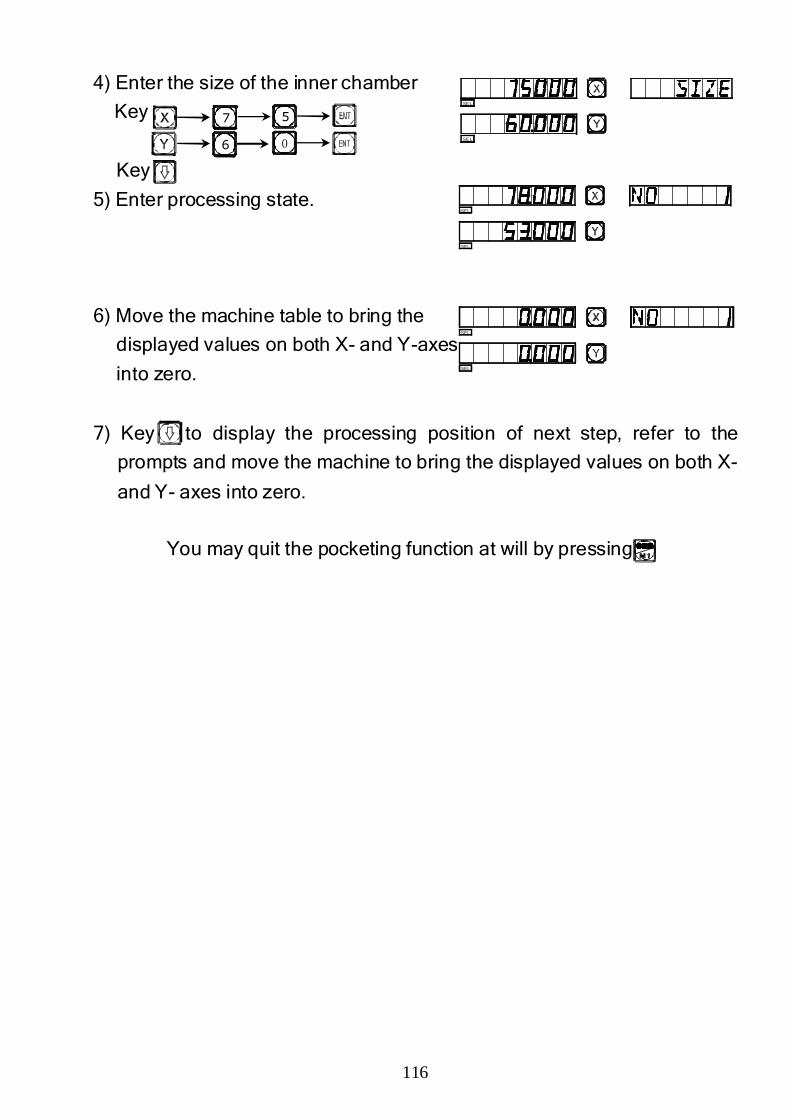
116
4) Enter the size of the inner chamber
Key
Key
5) Enter processing state.
6) Move the machine table to bring the
displayed values on both X- and Y-axes
into zero.
7) Key to display the processing position of next step, refer to the
prompts and move the machine to bring the displayed values on both X-
and Y- axes into zero.
You may quit the pocketing function at will by pressing
7 5
6 0
SE L
SE L
SEL
SEL
SEL
SEL
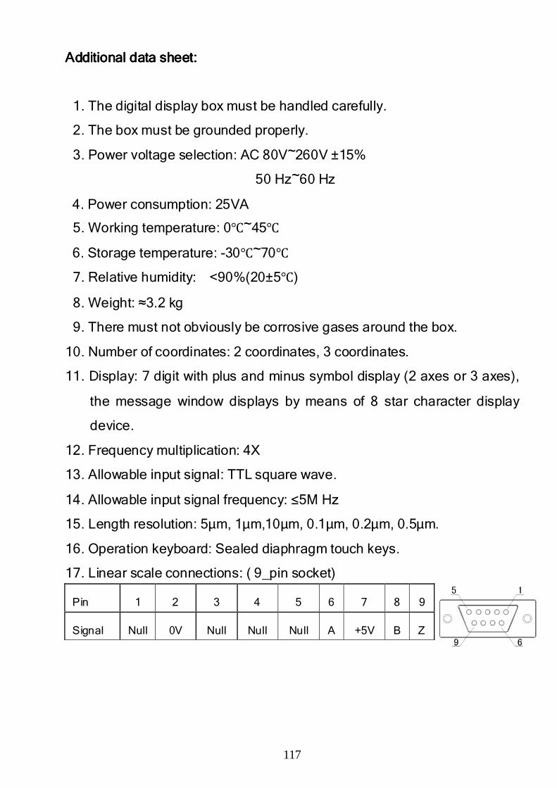
117
Additional Additional Additional Additional data data data data sheet:sheet:sheet:sheet:
1. The digital display box must be handled carefully.
2. The box must be grounded properly.
3. Power voltage selection: AC 80V~260V ±15%
50 Hz~60 Hz
4. Power consumption: 25VA
5. Working temperature: 0℃~45℃
6. Storage temperature: -30℃~70℃
7. Relative humidity: <90%(20±5℃)
8. Weight: ≈3.2 kg
9. There must not obviously be corrosive gases around the box.
10. Number of coordinates: 2 coordinates, 3 coordinates.
11. Display: 7 digit with plus and minus symbol display (2 axes or 3 axes),
the message window displays by means of 8 star character display
device.
12. Frequency multiplication: 4X
13. Allowable input signal: TTL square wave.
14. Allowable input signal frequency: ≤5M Hz
15. Length resolution: 5µm, 1µm,10µm, 0.1µm, 0.2µm, 0.5µm.
16. Operation keyboard: Sealed diaphragm touch keys.
17. Linear scale connections: ( 9_pin socket)
Pin 1 2 3 4 5 6 7 8 9
Signal Null 0V Null Null Null A +5V B Z
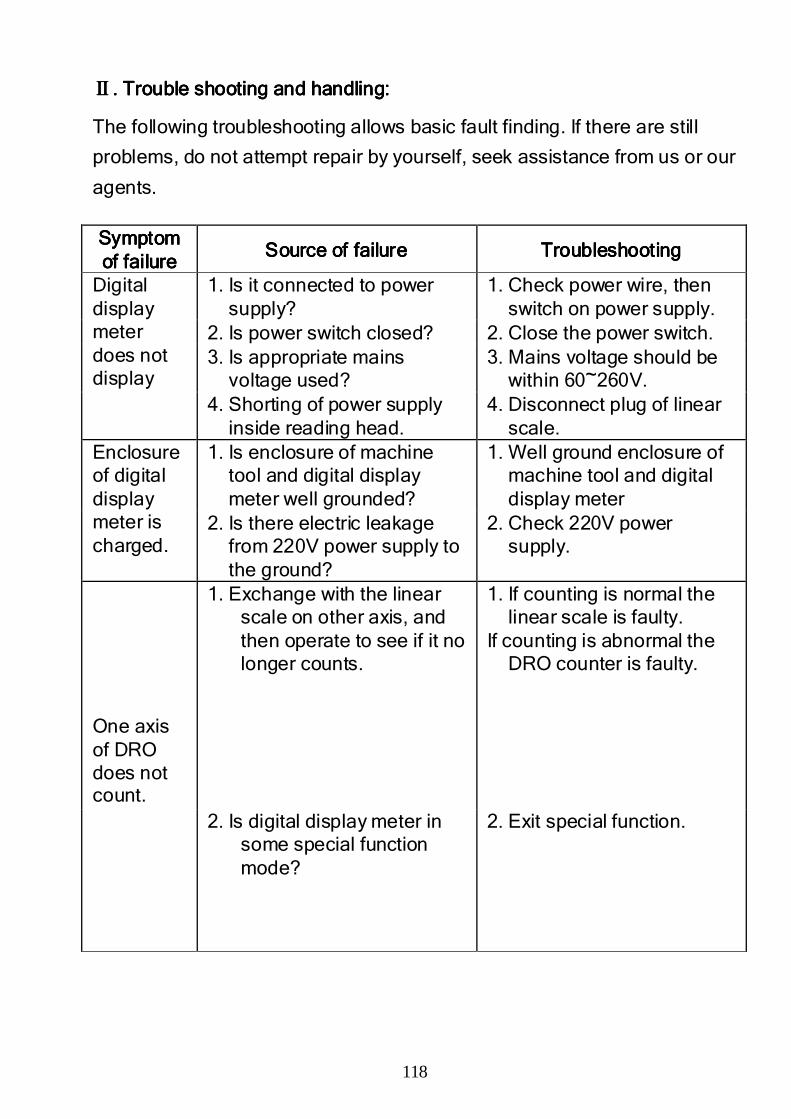
118
ⅡⅡⅡⅡ. Trouble shooting and handling:. Trouble shooting and handling:. Trouble shooting and handling:. Trouble shooting and handling:
The following troubleshooting allows basic fault finding. If there are still
problems, do not attempt repair by yourself, seek assistance from us or our
agents. Symptom Symptom Symptom Symptom of failureof failureof failureof failure
Source of failureSource of failureSource of failureSource of failure TroubleshootingTroubleshootingTroubleshootingTroubleshooting
Digital display meter does not display
1. Is it connected to power supply?
1. Check power wire, then switch on power supply.
2. Is power switch closed? 2. Close the power switch. 3. Is appropriate mains
voltage used? 3. Mains voltage should be
within 60~260V. 4. Shorting of power supply
inside reading head. 4. Disconnect plug of linear
scale. Enclosure of digital display meter is charged.
1. Is enclosure of machine tool and digital display meter well grounded?
1. Well ground enclosure of machine tool and digital display meter
2. Is there electric leakage from 220V power supply to the ground?
2. Check 220V power supply.
One axis of DRO does not count.
1. Exchange with the linear scale on other axis, and then operate to see if it no longer counts.
1. If counting is normal the linear scale is faulty.
If counting is abnormal the DRO counter is faulty.
2. Is digital display meter in some special function mode?
2. Exit special function.
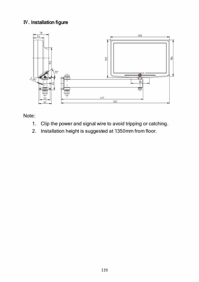
119
ⅣⅣⅣⅣ. Install. Install. Install. Installationationationation figurefigurefigurefigure
Note:
1. Clip the power and signal wire to avoid tripping or catching.
2. Installation height is suggested at 1350mm from floor.

SterlingSterlingSterlingSterling....
8F-2, No. 97 Taichung Kang Rd, Sec,3., Taichung 40755, Taiwan.
Tel: 04 2358 8535 | Fax: 04 2358 8530 | [email protected]
www.dro.com.tw