Digital Design: BINARY ARITHMETIC, DECODING AND MUX LOGIC UNITS Part - V
25
Chapter 10 Chapter 10 BINARY ARITHMETIC, DECODING AND MUX LOGIC UNITS
-
Upload
atush-jain -
Category
Education
-
view
29 -
download
0
Transcript of Digital Design: BINARY ARITHMETIC, DECODING AND MUX LOGIC UNITS Part - V
Chapter 10Chapter 10
BINARY ARITHMETIC,
DECODING AND MUX LOGIC UNITS

Ch10L5-"Digital Principles and Design", Raj Kamal, Pearson Education, 2006 2
Lesson 5
Multiplexer
Ch10L5-"Digital Principles and Design", Raj Kamal, Pearson Education, 2006 3
Outline
• Multiplexer • 2 of 1 and 4 of 1 line multiplexer• 8 of 1 • 4 of 16 line multiplexer• Multiplexers Arranged as tree

Ch10L5-"Digital Principles and Design", Raj Kamal, Pearson Education, 2006 4
Multiplexer• A circuit that sends the binary information
from one of the input line to the output and that line is selected as per the address or channel select bits.
• A circuit that selects the input line among the input lines as per channel-selector logic-inputs and gives that line input at the output. A multiplexer selects a unique input line according to the address or channel selector inputs to it

Ch10L5-"Digital Principles and Design", Raj Kamal, Pearson Education, 2006 5
Multiplexer Applications
• Sharing the Boolean function circuit outputs, ports, devices and resources
• Logic Design of circuits

Ch10L5-"Digital Principles and Design", Raj Kamal, Pearson Education, 2006 6
n to 1 Multiplexer
• A circuit, which takes the 2n -input line but presumes with only one = active and gives that at output
• Selection is using n-address (channel) select bits

Ch10L5-"Digital Principles and Design", Raj Kamal, Pearson Education, 2006 7
Outline
• Multiplexer • 2 of 1 and 4 of 1 line multiplexers• 8 of 1 line multiplexer• 4 of 16 line multiplexer• Multiplexers Arranged as tree
Ch10L5-"Digital Principles and Design", Raj Kamal, Pearson Education, 2006 8
2-channel input-selector (2 to 1 multiplexer)
• One channel selector pin A (= 0 for channel or Boolean function F0 and = 1 for channel F1)

Ch10L5-"Digital Principles and Design", Raj Kamal, Pearson Education, 2006 9
Multiplexer as Line Selector • Assume that we have two logic circuits
that provide the outputs. One is for a logic function F0 and other is for F1. We have to select only one by giving appropriate instruction at the pins called address pin or channel select pin A. A multiplexer will select for the output only one of F0 or F1

Ch10L5-"Digital Principles and Design", Raj Kamal, Pearson Education, 2006 10
2 of 1 Multiplexer
F0 F1 0 F0
Inputs Select Input Output I0 I1 A Y
F0 F1 1 F 1
F0 or F1I1I0
A
F0F1

Ch10L5-"Digital Principles and Design", Raj Kamal, Pearson Education, 2006 11
4 of 1 Multiplexer
F0 F1 F2 F3 0 0 F0
Inputs Select Input Output I0 I1 I2 I3 A1 A0 Y
F0 F1 F2 F3 0 1 F1F0 F1 F2 F3 1 0 F2F0 F1 F2 F3 1 1 F3

Ch10L5-"Digital Principles and Design", Raj Kamal, Pearson Education, 2006 12
4 of 1 Multiplexer
YF0 or F1 orF2 or F3I1
I0
A0
F0F1
I3I2F2
F3
A1
Ch10L5-"Digital Principles and Design", Raj Kamal, Pearson Education, 2006 13
Outline
• Multiplexer • 2 of 1 and 4 of 1 line multiplexers• 8 of 1 line multiplexer• 4 of 16 line multiplexer• Multiplexers Arranged as tree
Ch10L5-"Digital Principles and Design", Raj Kamal, Pearson Education, 2006 14
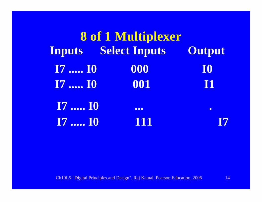
8 of 1 Multiplexer
I7 ..... I0 001 I1
Inputs OutputI7 ..... I0 I0
Y0
Select Inputs 000
I7 ..... I0 ... .I7 ..... I0 111 I7

Ch10L5-"Digital Principles and Design", Raj Kamal, Pearson Education, 2006 15
8 of 1 Multiplexer
YF0 or F1 orF2 or F3I1
I0
A0
F0F1
I3I2F2
F3
A1
I5I4F4
F5
I7I6F6
F7
A2
Ch10L5-"Digital Principles and Design", Raj Kamal, Pearson Education, 2006 16
Outline
• Multiplexer • 2 of 1 and 4 of 1 line multiplexers• 8 of 1 line multiplexer• 4 line of 16 line multiplexer • Multiplexers Arranged as tree
Ch10L5-"Digital Principles and Design", Raj Kamal, Pearson Education, 2006 17
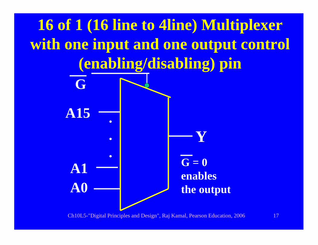
16 of 1 (16 line to 4line) Multiplexer with one input and one output control
(enabling/disabling) pin
A1A0
G
A15 ...
G = 0enables the output
Y

Ch10L5-"Digital Principles and Design", Raj Kamal, Pearson Education, 2006 18
16 of 1 (8 line to 3 line) Multiplexer with one output control (enabling/disabling) pin
A2A0
Y
OE
A1A0
A15 ...
OE = 0meansenable the input

Ch10L5-"Digital Principles and Design", Raj Kamal, Pearson Education, 2006 19
Outline
• Multiplexer • 2 of 1 and 4 of 1 line multiplexers• 8 of 1 line multiplexer• 4 of 16 line multiplexer• Multiplexers Arranged as tree

Ch10L5-"Digital Principles and Design", Raj Kamal, Pearson Education, 2006 20
Tree
• We get the (m of 1) multiplexing from i numbers of the (m’ of 1) multiplexers when the multiplexers arranged as a tree
• Here m = i.m’ where i is an integer and m’ = 2n where n is the number of channel selector lines at each of the i multiplexers

Ch10L5-"Digital Principles and Design", Raj Kamal, Pearson Education, 2006 21
Multiplexer Tree
YF0 or .. or F15
I0.I3
A3A2A1A0
I4..I7
I8..I11
I12..I15
Ch10L5-"Digital Principles and Design", Raj Kamal, Pearson Education, 2006 22
Summary

Ch10L5-"Digital Principles and Design", Raj Kamal, Pearson Education, 2006 23
Multiplexer• A multiplexer provides output path
(channel) for the one channel data from the number of channels at a given instant.
• Its important application is in sharing the circuits, ports, devices and resources.
• A number of multiplexers can be arranged in tree topology to obtain a bigger numbers of channel-multiplexer
• A multiplexer has control gate pin(s) for output enable
Ch10L5-"Digital Principles and Design", Raj Kamal, Pearson Education, 2006 24
End of Lesson 5 on
Multiplexer

Ch10L5-"Digital Principles and Design", Raj Kamal, Pearson Education, 2006 25
THANK YOU