Digital Deadweight Tester, Model CPD8500 EN · WIKA operating instructions digital deadweight...
122
Operating instructions EN Digital Deadweight Tester, Model CPD8500 Digital Deadweight Tester, Model CPD8500
Transcript of Digital Deadweight Tester, Model CPD8500 EN · WIKA operating instructions digital deadweight...
Operating instructions
ENDigital Deadweight Tester, Model CPD8500
Digital Deadweight Tester, Model CPD8500
2 WIKA operating instructions digital deadweight tester, model CPD8500
PN 0
0194
0800
1B 0
4/20
19 E
N
EN Operating instructions model CPD8500 Page 3 - 103
© 04/2019, Mensor, LP. All rights reserved.Mensor is a registered trademark of Mensor, LP. All other brand and product names are trademarks or registered trademarks of their respective companies.
Prior to starting any work, read the operating instructions!Keep for later use!
3WIKA operating instructions digital deadweight tester, model CPD8500
PN 0
0194
0800
1B 0
4/20
19 E
N
EN
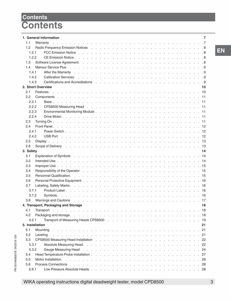
ContentsContents
1. General Information 71.1 Warranty . . . . . . . . . . . . . . . . . . . . . . . . . . . . . . . . . . . . 71.2 Radio Frequency Emission Notices . . . . . . . . . . . . . . . . . . . . . . . . . . . 8
1.2.1 FCC Emission Notice . . . . . . . . . . . . . . . . . . . . . . . . . . . . . . 81.2.2 CE Emission Notice . . . . . . . . . . . . . . . . . . . . . . . . . . . . . . . 8
1.3 Software License Agreement. . . . . . . . . . . . . . . . . . . . . . . . . . . . . . 81.4 Mensor Service Plus . . . . . . . . . . . . . . . . . . . . . . . . . . . . . . . . 9
1.4.1 After the Warranty . . . . . . . . . . . . . . . . . . . . . . . . . . . . . . . 91.4.2 Calibration Services. . . . . . . . . . . . . . . . . . . . . . . . . . . . . . . 91.4.3 Certifications and Accreditations . . . . . . . . . . . . . . . . . . . . . . . . . . 9
2. Short Overview 102.1 Features. . . . . . . . . . . . . . . . . . . . . . . . . . . . . . . . . . . . 102.2 Components . . . . . . . . . . . . . . . . . . . . . . . . . . . . . . . . . . 11
2.2.1 Base . . . . . . . . . . . . . . . . . . . . . . . . . . . . . . . . . . . 112.2.2 CPS8500 Measuring Head . . . . . . . . . . . . . . . . . . . . . . . . . . . 112.2.3 Environmental Monitoring Module . . . . . . . . . . . . . . . . . . . . . . . . . 112.2.4 Drive Motor. . . . . . . . . . . . . . . . . . . . . . . . . . . . . . . . . 11
2.3 Turning On . . . . . . . . . . . . . . . . . . . . . . . . . . . . . . . . . . . 112.4 Front Panel . . . . . . . . . . . . . . . . . . . . . . . . . . . . . . . . . . . 12
2.4.1 Power Switch . . . . . . . . . . . . . . . . . . . . . . . . . . . . . . . . 122.4.2 USB Port . . . . . . . . . . . . . . . . . . . . . . . . . . . . . . . . . 12
2.5 Display . . . . . . . . . . . . . . . . . . . . . . . . . . . . . . . . . . . . 132.6 Scope of Delivery . . . . . . . . . . . . . . . . . . . . . . . . . . . . . . . . 13
3. Safety 143.1 Explanation of Symbols . . . . . . . . . . . . . . . . . . . . . . . . . . . . . . 143.2 Intended Use . . . . . . . . . . . . . . . . . . . . . . . . . . . . . . . . . . 143.3 Improper Use . . . . . . . . . . . . . . . . . . . . . . . . . . . . . . . . . . 153.4 Responsibility of the Operator . . . . . . . . . . . . . . . . . . . . . . . . . . . . 153.5 Personnel Qualification. . . . . . . . . . . . . . . . . . . . . . . . . . . . . . . 153.6 Personal Protective Equipment . . . . . . . . . . . . . . . . . . . . . . . . . . . . 163.7 Labeling, Safety Marks . . . . . . . . . . . . . . . . . . . . . . . . . . . . . . . 16
3.7.1 Product Label . . . . . . . . . . . . . . . . . . . . . . . . . . . . . . . . 163.7.2 Symbols. . . . . . . . . . . . . . . . . . . . . . . . . . . . . . . . . . 16
3.8 Warnings and Cautions . . . . . . . . . . . . . . . . . . . . . . . . . . . . . . 174. Transport, Packaging and Storage 18
4.1 Transport . . . . . . . . . . . . . . . . . . . . . . . . . . . . . . . . . . . 184.2 Packaging and storage . . . . . . . . . . . . . . . . . . . . . . . . . . . . . . . 18
4.2.1 Transport of Measuring Heads CPS8500 . . . . . . . . . . . . . . . . . . . . . . 195. Installation 21
5.1 Mounting . . . . . . . . . . . . . . . . . . . . . . . . . . . . . . . . . . . 215.2 Leveling . . . . . . . . . . . . . . . . . . . . . . . . . . . . . . . . . . . . 215.3 CPS8500 Measuring Head Installation . . . . . . . . . . . . . . . . . . . . . . . . . 22
5.3.1 Absolute Measuring Head. . . . . . . . . . . . . . . . . . . . . . . . . . . . 225.3.2 Gauge Measuring Head . . . . . . . . . . . . . . . . . . . . . . . . . . . . 24
5.4 Head Temperature Probe Installation . . . . . . . . . . . . . . . . . . . . . . . . . . 275.5 Motor Installation . . . . . . . . . . . . . . . . . . . . . . . . . . . . . . . . . 285.6 Process Connections . . . . . . . . . . . . . . . . . . . . . . . . . . . . . . . 28
5.6.1 Low Pressure Absolute Heads . . . . . . . . . . . . . . . . . . . . . . . . . . 28

4 WIKA operating instructions digital deadweight tester, model CPD8500
PN 0
0194
0800
1B 0
4/20
19 E
N
EN
5.6.1.1 Zeroing & Spanning Setup . . . . . . . . . . . . . . . . . . . . . . . . . . 305.6.1.2 Operational Setup . . . . . . . . . . . . . . . . . . . . . . . . . . . . . 30
5.6.2 High Pressure Absolute Heads . . . . . . . . . . . . . . . . . . . . . . . . . . 305.6.2.1 Zeroing & Spanning Setup . . . . . . . . . . . . . . . . . . . . . . . . . . 315.6.2.2 Operational Setup . . . . . . . . . . . . . . . . . . . . . . . . . . . . . 31
5.6.3 Gauge Heads . . . . . . . . . . . . . . . . . . . . . . . . . . . . . . . . 315.6.3.1 Zeroing & Spanning Setup . . . . . . . . . . . . . . . . . . . . . . . . . . 325.6.3.2 Operational Setup . . . . . . . . . . . . . . . . . . . . . . . . . . . . . 32
5.7 Rear Panel . . . . . . . . . . . . . . . . . . . . . . . . . . . . . . . . . . . 325.7.1 Reference Supply Port . . . . . . . . . . . . . . . . . . . . . . . . . . . . . 335.7.2 Optional: Barometric Reference Port . . . . . . . . . . . . . . . . . . . . . . . . 335.7.3 Remote Communication Connections. . . . . . . . . . . . . . . . . . . . . . . . 33
6. Operation 346.1 General Operation . . . . . . . . . . . . . . . . . . . . . . . . . . . . . . . . 34
6.1.1 Power Up . . . . . . . . . . . . . . . . . . . . . . . . . . . . . . . . . 346.1.2 Setup Applications . . . . . . . . . . . . . . . . . . . . . . . . . . . . . . 346.1.3 Display Screen Features . . . . . . . . . . . . . . . . . . . . . . . . . . . . 34
6.2 Initial Setup. . . . . . . . . . . . . . . . . . . . . . . . . . . . . . . . . . . 366.2.1 Local Gravity Setup . . . . . . . . . . . . . . . . . . . . . . . . . . . . . . 366.2.2 Contact and Version Information Application . . . . . . . . . . . . . . . . . . . . . 366.2.3 Language Selection . . . . . . . . . . . . . . . . . . . . . . . . . . . . . . 376.2.4 Active Head Selection . . . . . . . . . . . . . . . . . . . . . . . . . . . . . 376.2.5 Head Motor Activation . . . . . . . . . . . . . . . . . . . . . . . . . . . . . 39
6.3 Application Selection and Parameter Inputs. . . . . . . . . . . . . . . . . . . . . . . . 406.4 Applications . . . . . . . . . . . . . . . . . . . . . . . . . . . . . . . . . . 41
6.4.1 Home Applications . . . . . . . . . . . . . . . . . . . . . . . . . . . . . . 416.4.1.1 Current Pressure Reading . . . . . . . . . . . . . . . . . . . . . . . . . . 426.4.1.2 Units and Pressure Type . . . . . . . . . . . . . . . . . . . . . . . . . . . 436.4.1.3 Zero . . . . . . . . . . . . . . . . . . . . . . . . . . . . . . . . . 436.4.1.4 Span . . . . . . . . . . . . . . . . . . . . . . . . . . . . . . . . . 456.4.1.5 sBar Graph . . . . . . . . . . . . . . . . . . . . . . . . . . . . . . . 476.4.1.6 Auxiliary Displays . . . . . . . . . . . . . . . . . . . . . . . . . . . . . 476.4.1.7 Uptime Clock . . . . . . . . . . . . . . . . . . . . . . . . . . . . . . 476.4.1.8 Tare Button . . . . . . . . . . . . . . . . . . . . . . . . . . . . . . . 486.4.1.9 Active Head . . . . . . . . . . . . . . . . . . . . . . . . . . . . . . . 486.4.1.10 Barometer . . . . . . . . . . . . . . . . . . . . . . . . . . . . . . . 48
6.4.2 Settings Application . . . . . . . . . . . . . . . . . . . . . . . . . . . . . . 496.4.2.1 Languages . . . . . . . . . . . . . . . . . . . . . . . . . . . . . . . 496.4.2.2 Brightness . . . . . . . . . . . . . . . . . . . . . . . . . . . . . . . 506.4.2.3 User Base Units/ Base Units Multiplier . . . . . . . . . . . . . . . . . . . . . . 506.4.2.4 Barometer Units . . . . . . . . . . . . . . . . . . . . . . . . . . . . . 516.4.2.5 Configuration . . . . . . . . . . . . . . . . . . . . . . . . . . . . . . 51
6.4.3 Limits Application . . . . . . . . . . . . . . . . . . . . . . . . . . . . . . 526.4.3.1 Ambient Tolerance Limits . . . . . . . . . . . . . . . . . . . . . . . . . . 526.4.3.2 Head Temperature Limit . . . . . . . . . . . . . . . . . . . . . . . . . . . 536.4.3.3 Pressure Stability Parameters . . . . . . . . . . . . . . . . . . . . . . . . . 53
6.4.4 Display Settings Application . . . . . . . . . . . . . . . . . . . . . . . . . . . 546.4.4.1 Reading Filter . . . . . . . . . . . . . . . . . . . . . . . . . . . . . . 546.4.4.2 Reading Resolution . . . . . . . . . . . . . . . . . . . . . . . . . . . . 556.4.4.3 Bar Graph . . . . . . . . . . . . . . . . . . . . . . . . . . . . . . . 55
Contents
5WIKA operating instructions digital deadweight tester, model CPD8500
PN 0
0194
0800
1B 0
4/20
19 E
N
EN
6.4.4.4 Tare . . . . . . . . . . . . . . . . . . . . . . . . . . . . . . . . . . 556.4.4.5 Uptime Clock . . . . . . . . . . . . . . . . . . . . . . . . . . . . . . 56
6.4.5 Head Information Application . . . . . . . . . . . . . . . . . . . . . . . . . . 566.4.6 Remote Settings Application . . . . . . . . . . . . . . . . . . . . . . . . . . . 58
6.4.6.1 Remote Command Set . . . . . . . . . . . . . . . . . . . . . . . . . . . 586.4.6.2 Remote Communication Settings. . . . . . . . . . . . . . . . . . . . . . . . 59
6.4.7 Information Application . . . . . . . . . . . . . . . . . . . . . . . . . . . . 606.4.8 Troubleshooting Application . . . . . . . . . . . . . . . . . . . . . . . . . . . 616.4.9 Service Application . . . . . . . . . . . . . . . . . . . . . . . . . . . . . . 62
7. Remote Operation 647.1 Remote Operating Parameters . . . . . . . . . . . . . . . . . . . . . . . . . . . . 647.2 Command Set. . . . . . . . . . . . . . . . . . . . . . . . . . . . . . . . . . 647.3 IEEE-488 . . . . . . . . . . . . . . . . . . . . . . . . . . . . . . . . . . . 64
7.3.1 IEEE-488.2 Commands . . . . . . . . . . . . . . . . . . . . . . . . . . . . 647.4 Ethernet . . . . . . . . . . . . . . . . . . . . . . . . . . . . . . . . . . . . 647.5 Serial . . . . . . . . . . . . . . . . . . . . . . . . . . . . . . . . . . . . . 65
7.5.1 Serial Cable Requirements . . . . . . . . . . . . . . . . . . . . . . . . . . . 657.6 Mensor Command Set . . . . . . . . . . . . . . . . . . . . . . . . . . . . . . . 66
7.6.1 Command and Query Format . . . . . . . . . . . . . . . . . . . . . . . . . . 667.6.2 Command Set Definitions . . . . . . . . . . . . . . . . . . . . . . . . . . . . 667.6.3 Output Formats . . . . . . . . . . . . . . . . . . . . . . . . . . . . . . . 667.6.4 Mensor Commands and Queries . . . . . . . . . . . . . . . . . . . . . . . . . 677.6.5 Units Command Syntax for Measurement Units . . . . . . . . . . . . . . . . . . . . 71
7.7 CPD8500 Command Set . . . . . . . . . . . . . . . . . . . . . . . . . . . . . . 727.7.1 Command and Query Format . . . . . . . . . . . . . . . . . . . . . . . . . . 727.7.2 Command Set Definitions . . . . . . . . . . . . . . . . . . . . . . . . . . . . 727.7.3 CPD8500 Commands and Queries . . . . . . . . . . . . . . . . . . . . . . . . 72
7.8 Error Codes . . . . . . . . . . . . . . . . . . . . . . . . . . . . . . . . . . 748. Maintenance and Recalibration 77
8.1 Maintenance . . . . . . . . . . . . . . . . . . . . . . . . . . . . . . . . . . 778.1.1 Beyond the Warranty . . . . . . . . . . . . . . . . . . . . . . . . . . . . . 778.1.2 Measuring Head Cleaning . . . . . . . . . . . . . . . . . . . . . . . . . . . 77
8.1.2.1 Absolute Measuring Head . . . . . . . . . . . . . . . . . . . . . . . . . . 778.1.2.2 Low Pressure Gauge Measuring Head . . . . . . . . . . . . . . . . . . . . . . 818.1.2.3 High Pressure Gauge Measuring Head. . . . . . . . . . . . . . . . . . . . . . 83
8.1.3 Spare Parts . . . . . . . . . . . . . . . . . . . . . . . . . . . . . . . . 878.1.3.1 Environmental Monitoring Module Replacement . . . . . . . . . . . . . . . . . . 878.1.3.2 Absolute Accessory Kit Replacement . . . . . . . . . . . . . . . . . . . . . . 888.1.3.3 Gauge Accessory Kit Replacement . . . . . . . . . . . . . . . . . . . . . . . 888.1.3.4 Vacuum Transducer Replacement . . . . . . . . . . . . . . . . . . . . . . . 888.1.3.5 Barometric Reference Replacement. . . . . . . . . . . . . . . . . . . . . . . 90
8.2 Recalibration . . . . . . . . . . . . . . . . . . . . . . . . . . . . . . . . . . 918.2.1 Calibration Services by Mensor or WIKA worldwide . . . . . . . . . . . . . . . . . . . 918.2.2 Environment . . . . . . . . . . . . . . . . . . . . . . . . . . . . . . . . 91
8.2.2.1 Pressure Calibration Setup for CPD8500 . . . . . . . . . . . . . . . . . . . . . 918.2.3 Pressure Standards . . . . . . . . . . . . . . . . . . . . . . . . . . . . . . 928.2.4 Media . . . . . . . . . . . . . . . . . . . . . . . . . . . . . . . . . . 928.2.5 Calibration Data . . . . . . . . . . . . . . . . . . . . . . . . . . . . . . . 928.2.6 Calibration Application . . . . . . . . . . . . . . . . . . . . . . . . . . . . . 93
Contents
6 WIKA operating instructions digital deadweight tester, model CPD8500
PN 0
0194
0800
1B 0
4/20
19 E
N
EN
8.2.6.1 One Point Calibration . . . . . . . . . . . . . . . . . . . . . . . . . . . . 948.2.6.2 Two Point Calibration . . . . . . . . . . . . . . . . . . . . . . . . . . . . 968.2.6.3 Linearization . . . . . . . . . . . . . . . . . . . . . . . . . . . . . . . 97
8.2.7 Mass Calibration Application . . . . . . . . . . . . . . . . . . . . . . . . . . . 998.2.8 Head Settings Application. . . . . . . . . . . . . . . . . . . . . . . . . . . . 101
8.2.8.1 New Head Addition . . . . . . . . . . . . . . . . . . . . . . . . . . . . 1038.2.9 Reference Level . . . . . . . . . . . . . . . . . . . . . . . . . . . . . . . 104
9. Dismounting, Return and Disposal 1059.1 Dismounting . . . . . . . . . . . . . . . . . . . . . . . . . . . . . . . . . . 1059.2 Return . . . . . . . . . . . . . . . . . . . . . . . . . . . . . . . . . . . . 1069.3 Disposal. . . . . . . . . . . . . . . . . . . . . . . . . . . . . . . . . . . . 106
10. Specifications 10710.1 Measuring Head . . . . . . . . . . . . . . . . . . . . . . . . . . . . . . . . . 10710.2 Base Instrument . . . . . . . . . . . . . . . . . . . . . . . . . . . . . . . . . 10810.3 Approvals and Certificates . . . . . . . . . . . . . . . . . . . . . . . . . . . . . 10910.4 Dimensions in mm (in) . . . . . . . . . . . . . . . . . . . . . . . . . . . . . . . 110
10.4.1 Absolute . . . . . . . . . . . . . . . . . . . . . . . . . . . . . . . . . 11010.4.2 Gauge . . . . . . . . . . . . . . . . . . . . . . . . . . . . . . . . . . 111
11. Accessories 11211.1 Barometric Reference Sensor . . . . . . . . . . . . . . . . . . . . . . . . . . . . 112
11.1.1 Bidirectional Pressure Emulation . . . . . . . . . . . . . . . . . . . . . . . . . 11211.1.2 Emulation Mode Accuracy . . . . . . . . . . . . . . . . . . . . . . . . . . . 11211.1.3 Barometric Reference Calibration . . . . . . . . . . . . . . . . . . . . . . . . . 112
11.2 Vacuum Transducer . . . . . . . . . . . . . . . . . . . . . . . . . . . . . . . . 11211.3 Absolute Accessory Kit. . . . . . . . . . . . . . . . . . . . . . . . . . . . . . . 11311.4 Vacuum Pump Requirements . . . . . . . . . . . . . . . . . . . . . . . . . . . . 11411.5 Gauge Accessory Kit . . . . . . . . . . . . . . . . . . . . . . . . . . . . . . . 11411.6 Upgrade Accessory Kit. . . . . . . . . . . . . . . . . . . . . . . . . . . . . . . 11511.7 External Mass Set . . . . . . . . . . . . . . . . . . . . . . . . . . . . . . . . 11511.8 EMM Calibration Sled . . . . . . . . . . . . . . . . . . . . . . . . . . . . . . . 11611.9 Barometric Reference Calibration Sled . . . . . . . . . . . . . . . . . . . . . . . . . 117
12. Appendix 11812.1 Measurement Units . . . . . . . . . . . . . . . . . . . . . . . . . . . . . . . . 11812.2 Conversion Factors, PSI . . . . . . . . . . . . . . . . . . . . . . . . . . . . . . 11812.3 Conversion Factors, Millitorr . . . . . . . . . . . . . . . . . . . . . . . . . . . . . 12012.4 Conversion Factors, Pascal . . . . . . . . . . . . . . . . . . . . . . . . . . . . . 121
Declarations of conformity can be found online at www.wika.com.
Contents

7WIKA operating instructions digital deadweight tester, model CPD8500
PN 0
0194
0800
1B 0
4/20
19 E
N
EN
1. General Information
■ The CPD8500 digital deadweight tester described in the operating instructions has been designed and manufactured using state-of-the-art technology. All components are subject to stringent quality and environmental criteria during production. Our management systems are certified to ISO 9001 and ISO 14001.
■ These operating instructions contain important information on handling the instrument. Working safely requires that all safety instructions and work instructions are observed.
■ Observe the relevant local accident prevention regulations and general safety regulations for the instrument's operating range.
■ The operating instructions are part of the instrument and must be kept in the immediate vicinity of the instrument and readily accessible to skilled personnel at any time. Pass the operating instructions onto the next operator or owner of the instrument.
■ Skilled personnel must have carefully read and understood the operating instructions prior to beginning any work.
■ The general terms and conditions contained in the sales documentation shall apply.
■ Subject to technical modifications.
■ Factory calibrations / A2LA / DKD/DAkkS calibrations are carried out in accordance with international standards.
■ Further information:Mensor Corporation- Address 201 Barnes Dr., San Marcos, TX 78666- Internet address: www.mensor.com- Relevant data sheet: CT 32.05- Application consultant: Tel.: (+1) 512-396-4200
(+1) 800-984-4200 (USA only)Fax: (+1) 512-396-1820E-Mail: [email protected]@mensor.com
Importer for Europe
WIKA Alexander Wiegand SE & Co. KG
- Address Alexander Wiegand-Straße 63911 Klingenberg, Germany
- Internet address: www.wika.de / www.wika.com- Relevant data sheet: CT 32.05- Application consultant: Tel.: (+49) 9372/132-5015
Fax: (+49) 9372/132-8767E-Mail: [email protected]
1.1 Warranty All products manufactured by Mensor are warranted to be free of defects in workmanship and materials for a period of two years from the date of shipment. No other express warranty is given, and no affirmation of Seller, by words or actions, shall constitute a warranty. SELLER DISCLAIMS ANY IMPLIED WARRANTIES OF MERCHANTABILITY OR FITNESS FOR ANY PARTICULAR
1. General information

8 WIKA operating instructions digital deadweight tester, model CPD8500
PN 0
0194
0800
1B 0
4/20
19 E
N
EN
PURPOSES WHATSOEVER. If any defect in workmanship or material should develop under conditions of normal use and service within the warranty period, repairs will be made at no charge to the original purchaser, upon delivery of the product(s) to the factory, shipping charges prepaid. If inspection by Mensor or its authorized representative reveals that the product was damaged by accident, alteration, misuse, abuse, faulty installation or other causes beyond the control of Mensor, this warranty does not apply. The judgment of Mensor will be final as to all matters concerning condition of the product, the cause and nature of a defect, and the necessity or manner of repair. Service, repairs or disassembly of the product in any manner, performed without specific factory permission, voids this warranty.LIMITED WARRANTY applies to any CPD8500 manufactured as an upgrade of an existing CPD8000/DPG10. Any reused parts including but not limited to the internal load cell, vacuum box and the enclosed components are excluded from Mensor's Warranty coverage.MENSOR MAKES NO WARRANTY OF ANY KIND WITH REGARD TO THIS MANUAL, INCLUDING, BUT NOT LIMITED TO, THE IMPLIED WARRANTIES OF MERCHANTABILITY AND FITNESS FOR A PARTICULAR PURPOSE. Mensor shall not be liable for errors contained herein or for incidental or consequential damages in connection with the furnishing, performance, or use of this material.
1.2 Radio Frequency Emission Notices
USE SHIELDED CABLES TO CONNECT EXTERNAL DEVICES TO THIS INSTRUMENT TO MINIMIZE RF RADIATION
1.2.1 FCC Emission NoticeThis equipment has been tested and found to comply with the limits for a Class A digital device, pursuant to part 15 of the FCC Rules. These limits are designed to provide reasonable protection against harmful interference when the equipment is operated in a commercial environment. This equipment generates, uses, and can radiate radio frequency energy and, if not installed and used in accordance with the instruction manual, may cause harmful interference to radio communications. Operation of this equipment in a residential area is likely to cause harmful interference in which case the user will be required to correct the interference at his or her own expense.
1.2.2 CE Emission NoticeThis equipment is of the emission class A, intended for operation in industrials environments. It can cause interference under certain circumstances if operated in other environments, i.e. residential or commercial areas. In this case, the user may be asked to take appropriate measures to correct it.
1.3 Software License AgreementThis product contains intellectual property, i.e. software programs, that are licensed for use by the end user/customer (hereinafter “end user”).This is not a sale of such intellectual property.The end user shall not copy, disassemble or reverse compile the software program.
The software programs are provided to the end user “as is” without warranty of any kind, either express or implied, including, but not limited to, warranties of merchantability and fitness for a particular purpose. The entire risk of the quality and performance of the software program is with the end user.
Mensor and its suppliers shall not be held to any liability for any damages suffered or incurred by the end user (including, but not limited to, general, special, consequential or incidental damages including damages for loss of business profits, business interruption, loss of business information and the like), arising from or in connection with the delivery, use or performance of the software program.
1. General Information
9WIKA operating instructions digital deadweight tester, model CPD8500
PN 0
0194
0800
1B 0
4/20
19 E
N
EN
1.4 Mensor Service Plus1.4.1 After the WarrantyMensor’s concern with the performance of this instrument is not limited to the warranty period. We provide complete repair, calibration and certification services after the warranty for a nominal fee.
1.4.2 Calibration ServicesIn addition to servicing our own products Mensor can perform a complete pressure calibration service, up to 20,000 psi, for all of your pressure instruments. This service includes an accredited calibration.
1.4.3 Certifications and AccreditationsMensor is registered to ISO 9001:2008. The calibration program at Mensor is accredited by A2LA, as complying with both the ISO/IEC 17025:2005 and the ANSI/NCSL Z540-1-1994 standards.
1. General Information
10 WIKA operating instructions digital deadweight tester, model CPD8500
PN 0
0194
0800
1B 0
4/20
19 E
N
EN
2. Short Overview
2. Short Overview
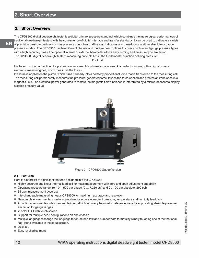
The CPD8500 digital deadweight tester is a digital primary pressure standard, which combines the metrological performances of traditional deadweight testers with the convenience of digital interface and transfer standards. It can be used to calibrate a variety of precision pressure devices such as pressure controllers, calibrators, indicators and transducers in either absolute or gauge pressure modes. The CPD8500 has two different chassis and multiple head options to cover absolute and gauge pressure types with a high accuracy class. The optional internal or external barometer allows easy zeroing and pressure type emulation. The CPD8500 digital deadweight tester’s measuring principle lies in the fundamental equation defining pressure:
P = F / A
It is based on the connection of a piston-cylinder assembly, whose surface area A is perfectly known, with a high accuracy electronic measuring cell, which measures the force F.Pressure is applied on the piston, which turns it linearly into a perfectly proportional force that is transferred to the measuring cell. The measuring cell permanently measures the pressure-generated force. It uses the force applied and creates an imbalance in a magnetic field. The electrical power generated to restore the magnetic field’s balance is interpreted by a microprocessor to display a stable pressure value.
Figure 2.1 CPD8500 Gauge Version
2.1 FeaturesHere is a short list of significant features designed into the CPD8500:
■ Highly accurate and linear internal load cell for mass measurement with zero and span adjustment capability ■ Operating pressure range from 0… 500 bar gauge (0 … 7,250 psi) and 0 .... 20 bar absolute (290 psi) ■ 35 ppm measurement accuracy ■ Interchangeable measuring heads CPS8500 for maximum accuracy and resolution ■ Removable environmental monitoring module for accurate ambient pressure, temperature and humidity feedback ■ An optional removable / interchangeable internal high accuracy barometric reference transducer providing absolute pressure
emulation for gauge ranges ■ 7” color LCD with touch screen ■ Support for multiple head configurations on one chassis ■ Multiple languages; change the language for on-screen text and number/date formats by simply touching one of the “national
flag” icons available in the setup screen. ■ Desk top ■ Easy level adjustment
11WIKA operating instructions digital deadweight tester, model CPD8500
PN 0
0194
0800
1B 0
4/20
19 E
N
EN
2. Short overview
2.2 Components2.2.1 BaseThe base is composed of:
■ The measuring load cell, which measures the force applied by the head ■ The Environmental Monitoring Module ■ The electronic assembly which ensures stable pressure calculation, the display as well as remote communication ■ Optional internal barometric reference for pressure emulation ■ Precision vacuum sensor (absolute base only) for detection of stable vacuum pressure ■ The lubrication valves to automatically switch the lubrication circuit of the measuring head from atmospheric pressure to the
measured pressure 2.2.2 CPS8500 Measuring HeadThe measuring head CPS8500 is designed for containing, operating and protecting the piston-cylinder assembly. The measuring heads are designed to operate with pure gas with the piston cylinder being lubricated with gas only for absolute versions and gas or oil (depending on the range) for gauge versions. The measuring heads are available in various versions:
■ Model 610 - absolute head ■ Model 110 - low pressure gauge head ■ Model 111 - medium pressure gauge head ■ Model 410 - high pressure gauge head
Each measuring head is characterized by a nominal coefficient, Kn. This is a conversion factor specific to each measuring head, representing the pressure value per kilogram converted in proportion to the head’s cross sectional area. This conversion factor is either represented in bar/ kg or psi/kg.
2.2.3 Environmental Monitoring ModuleThe Environmental Monitoring Module (EMM) accurately detects the ambient conditions and provide feedback to the electronic assembly inside the Base for easy adaptation of measurements corresponding to any changes in ambient conditions. The EMM consists of an ambient pressure, temperature and relative humidity sensor. The EMM continuously monitors the change in ambient conditions in real time. Whenever these conditions vary in proportions that might noticeably alter the measuring performance, the CPD8500 recommends the user to perform a span calibration for the internal load cell, this is explained in section 6.4.1.4. 2.2.4 Drive MotorStable pressure measurement requires the piston-cylinder assembly inside the measuring head to spin at a fixed rate. The CPD8500 supports either a brushed DC or a brushless DC motor.
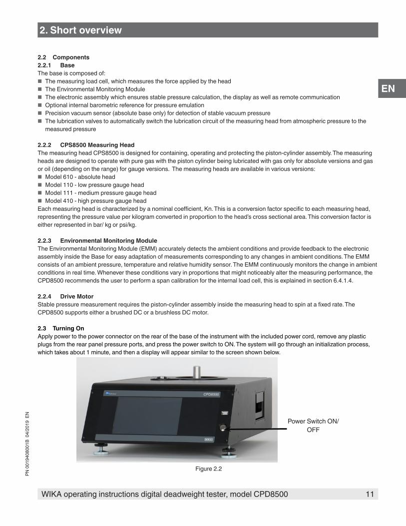
2.3 Turning OnApply power to the power connector on the rear of the base of the instrument with the included power cord, remove any plastic plugs from the rear panel pressure ports, and press the power switch to ON. The system will go through an initialization process, which takes about 1 minute, and then a display will appear similar to the screen shown below.
Power Switch ON/OFF
Figure 2.2

12 WIKA operating instructions digital deadweight tester, model CPD8500
PN 0
0194
0800
1B 0
4/20
19 E
N
EN
2. Short overview
Earth Ground! Any power adapters or surge protection devices that negate the protective earth ground should not be used. The power cord must be accessible and contain a protective earth ground. Do not position the equipment so that it is difficult to remove the power cord.
To see information about the configuration of your new CPD8500, touch the Information Application (App) icon [ ] on the menu and a window will appear listing the Mensor contact information, model number and the transducers that are installed. Press the Home App [ ] to return to the main screen.
Figure 2.3 Information application
2.4 Front PanelThe CPD8500 front panel includes an 7” color LCD display with touch screen. Operator input is accomplished by pressing the words or symbols and the App icons presented on the display. There is a single discrete on/off button and a USB on the right hand side. The front panel also shows the model number designation and brand logos.
2.4.1 Power SwitchThe power switch is a two-state device with an action similar to that of a ball point pen. Push the button with enough force to latch it in to turn the unit ON. Push it again to release it to turn the system OFF.
If power to the instrument is interrupted while ON it will shut down until the power is restored, then immediately resume operation.
2.4.2 USB PortThe front panel USB port is the Host USB and is intended for software upgrades, loading new head information and future expansion. Section 6 Operation explains this in detail.

13WIKA operating instructions digital deadweight tester, model CPD8500
PN 0
0194
0800
1B 0
4/20
19 E
N
EN
2.5 DisplayThe display is made up of two sections. In the main screen (“Home Application”), the left three fourths shows the operating screen displaying the active pressure reading, units, mode (absolute or gauge), active head information, an uptime clock (if enabled), a bar graph (if enabled), an auto zero, span and tare button (if enabled) and any auxiliary displays that have been chosen. The right one fourth of the screen has Application Icons (“Apps”) for setting general instrument settings, lzimits, display settings, head information, instrument information plus a “Next Page” button [ ] that, when pressed, shows a second and third page of icons for remote communication, troubleshooting and service applications.
Operating Screen Settings Apps
Active Head InformationZero, Span or Optional Tare
Current Pressure Value Optional Bar graph
Units / Pressure Type
Auxiliary Displays {
Motor Status Icon Uptime Clock
Buttons, Labels and Windows: The CPD8500 touch screen has many buttons with relevant graphic icons or text which, when touched, will open a related window where changes can be made or information viewed. Some of these buttons will toggle from one state to another, others present choices or display a numerical data entry screen. Text or icons that are displayed, but do not respond to being touched, are called labels or windows. Operators will quickly become accustomed to the particular characteristics of the frequently used buttons.
Main Screen: The main screen or “Home Application”, appears after power-up. This screen contains the operating screen and Settings application screen. It will remain as configured after a power cycle.
Operating screen: The operating screen (left 3/4 of the main screen) contains information relevant to the measurement. Up to three auxiliary displays can be shown simultaneously along with the current pressure value
2.6 Scope of Delivery
■ Digital Deadweight Tester CPD8500 base ■ Measuring Head CPS8500 (if ordered) ■ Power cord with 1.5 m (5 ft) length ■ Drive Motor (if absolute unit ordered) ■ Absolute accessory kit (if absolute unit ordered) ■ Gauge accessory kit (if gauge unit ordered) ■ Operating instruction ■ USB with Head Information ■ Factory calibration certificate
Cross-check scope of delivery with delivery note.
2. Short overview
14 WIKA operating instructions digital deadweight tester, model CPD8500
PN 0
0194
0800
1B 0
4/20
19 E
N
EN
3. Safety
3. Safety
3.1 Explanation of Symbols
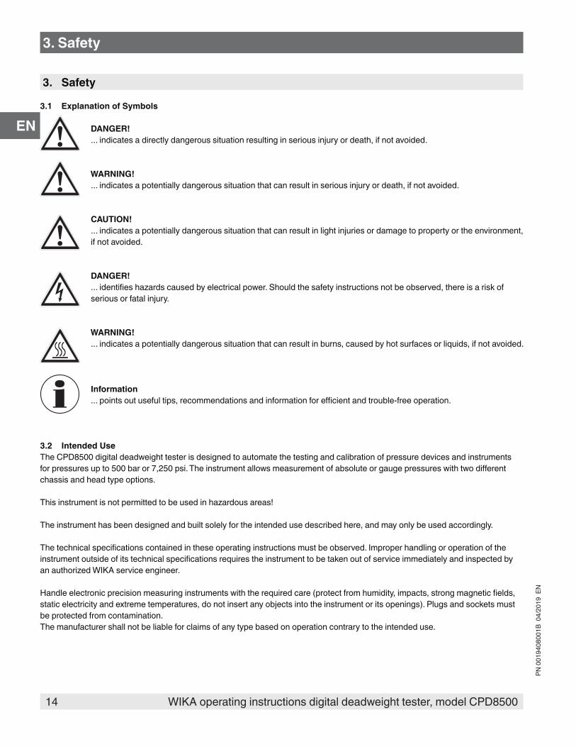
DANGER!... indicates a directly dangerous situation resulting in serious injury or death, if not avoided.
WARNING!... indicates a potentially dangerous situation that can result in serious injury or death, if not avoided.
CAUTION!... indicates a potentially dangerous situation that can result in light injuries or damage to property or the environment, if not avoided.
DANGER!... identifies hazards caused by electrical power. Should the safety instructions not be observed, there is a risk of serious or fatal injury.
WARNING!... indicates a potentially dangerous situation that can result in burns, caused by hot surfaces or liquids, if not avoided.
Information... points out useful tips, recommendations and information for efficient and trouble-free operation.
3.2 Intended UseThe CPD8500 digital deadweight tester is designed to automate the testing and calibration of pressure devices and instruments for pressures up to 500 bar or 7,250 psi. The instrument allows measurement of absolute or gauge pressures with two different chassis and head type options.
This instrument is not permitted to be used in hazardous areas!
The instrument has been designed and built solely for the intended use described here, and may only be used accordingly.
The technical specifications contained in these operating instructions must be observed. Improper handling or operation of the instrument outside of its technical specifications requires the instrument to be taken out of service immediately and inspected by an authorized WIKA service engineer.
Handle electronic precision measuring instruments with the required care (protect from humidity, impacts, strong magnetic fields, static electricity and extreme temperatures, do not insert any objects into the instrument or its openings). Plugs and sockets must be protected from contamination.The manufacturer shall not be liable for claims of any type based on operation contrary to the intended use.
15WIKA operating instructions digital deadweight tester, model CPD8500
PN 0
0194
0800
1B 0
4/20
19 E
N
EN
3.3 Improper Use
WARNING!Injuries through improper useImproper use of the instrument can lead to hazardous situations and injuries.
▶ Refrain from unauthorized modifications to the instrument. ▶ Do not use the instrument within hazardous areas. ▶ Do not use the instrument with abrasive or viscous media.
Any use beyond or different to the intended use is considered as improper use. Do not use this instrument in safety or emergency stop devices.
3.4 Responsibility of the OperatorThe instrument is used in the industrial sector. The operator is therefore responsible for legal obligations regarding safety at work.
The safety instructions within these operating instructions, as well as the safety, accident prevention and environmental protection regulations for the application area must be maintained.
The operator is obliged to maintain the product label in a legible condition.
To ensure safe working on the instrument, the operating company must ensure that ■ suitable first-aid equipment is available and aid is provided whenever required. ■ the operating personnel are regularly instructed in all topics regarding work safety, first aid and environmental protection and
know the operating instructions and in particular, the safety instructions contained therein. ■ the instrument is suitable for the particular application in accordance with its intended use. ■ personal protective equipment is available.
3.5 Personnel Qualification
WARNING!Risk of injury should qualification be insufficientImproper handling can result in considerable injury and damage to equipment.
▶ The activities described in these operating instructions may only be carried out by skilled personnel who have the qualifications described below.
Skilled personnelSkilled personnel, authorized by the operator, are understood to be personnel who, based on their technical training, knowledge of measurement and control technology and on their experience and knowledge of country-specific regulations, current standards and directives, are capable of carrying out the work described and independently recognizing potential hazards.
Operating personnelThe personnel trained by the operator are understood to be personnel who, based on their education, knowledge and experience, are capable of carrying out the work described and independently recognizing potential hazards.
Special knowledge for working with instruments for hazardous areas:The skilled (electrical) personnel must have knowledge of ignition protection types, regulations and provisions for equipment in hazardous areas.Special operating conditions require further appropriate knowledge, e.g. of aggressive media.
3. Safety
16 WIKA operating instructions digital deadweight tester, model CPD8500
PN 0
0194
0800
1B 0
4/20
19 E
N
EN
3.6 Personal Protective EquipmentThe personal protective equipment is designed to protect the skilled personnel from hazards that could impair their safety or health during work. When carrying out the various tasks on and with the instrument, the skilled personnel must wear personal protective equipment.
Follow the instructions displayed in the work area regarding personal protective equipment!
The requisite personal protective equipment must be provided by the operating company.
Wear clean and protective gloves!Protect the instrument with contamination and friction.
3.7 Labeling, Safety Marks
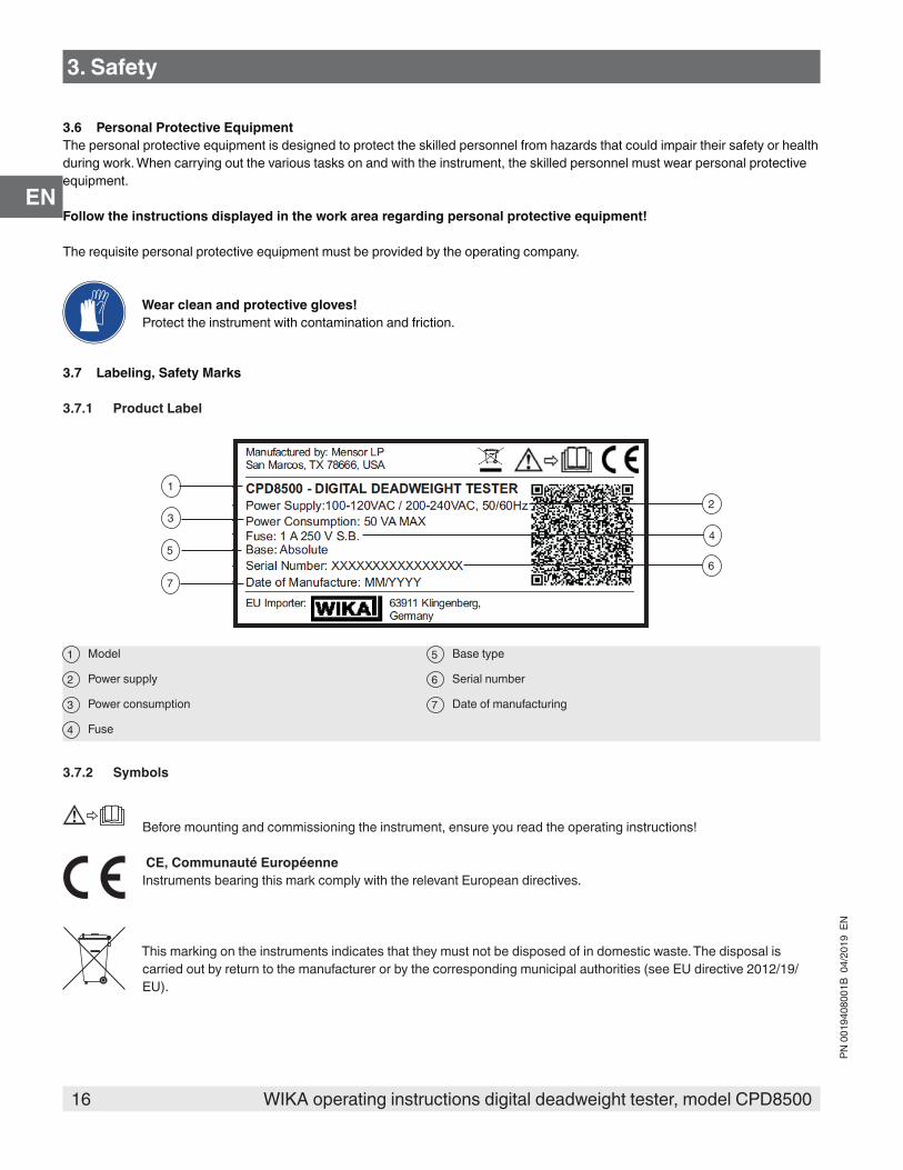
3.7.1 Product Label
3
67
5
21
4
1 Model 5 Base type
2 Power supply 6 Serial number
3 Power consumption 7 Date of manufacturing
Fuse
3.7.2 Symbols
Before mounting and commissioning the instrument, ensure you read the operating instructions!
CE, Communauté Européenne Instruments bearing this mark comply with the relevant European directives.
This marking on the instruments indicates that they must not be disposed of in domestic waste. The disposal is carried out by return to the manufacturer or by the corresponding municipal authorities (see EU directive 2012/19/EU).
4
3. Safety

17WIKA operating instructions digital deadweight tester, model CPD8500
PN 0
0194
0800
1B 0
4/20
19 E
N
EN
3.8 Warnings and Cautions
WARNING!HIGH PRESSURE! High pressure gases are potentially hazardous. Energy stored in these gases and liquids can be released suddenly and with extreme force. High pressure systems should be assembled and operated only by personnel who have been trained in proper safety practices.
WARNING!NOT EXPLOSION PROOF! Installation of this instrument in an area requiring devices rated as intrinsically safe is not recommended.
WARNING!POSSIBLE INJURY! The tubing, valves, and other apparatus attached to the gauge must be adequate for the maximum pressure which will be applied, otherwise physical injury to the operator or bystanders is possible.
CAUTIONUSE THE PROPER PRESSURE MEDIUM! Use only clean, dry air or nitrogen unless otherwise specified by Mensor.
CAUTIONAs with most sensitive electronic equipment, switch the power switch off before connecting or disconnecting to a power source to prevent data loss. Do not position the equipment so that it is difficult to disconnect the AC power cord.
WARNING!Detachable main power supply cord with inadequate ratings should not be used. See Section 10. Specifications for power ratings.
Additional Warning and Caution notices are found throughout this manual.
3. Safety

18 WIKA operating instructions digital deadweight tester, model CPD8500
PN 0
0194
0800
1B 0
4/20
19 E
N
EN
4. Transport, Packaging and Storage
4.1 TransportCheck the digital deadweight tester model CPD8500 for any damage that may have been caused by transport.Obvious damage must be reported immediately.
CAUTION!Damage through improper transportWith improper transport, a high level of damage to property can occur.
▶ When unloading packed goods upon delivery as well as during internal transport, proceed carefully and observe the symbols on the packaging.
▶ With internal transport, observe the instructions in chapter 4.2 “Packaging and storage”.
If the instrument is transported from a cold into a warm environment, the formation of condensation may result in instrument malfunction. Before putting it back into operation, wait for the instrument temperature and the room temperature to equalize.
4.2 Packaging and storageThe CPD8500 digital deadweight tester is packaged in a custom transport case especially designed to maintain the performances of the instrument in normal transportation conditions. Do not remove packaging until just before mounting. The base, the measuring head, the drive motor along with all the accessories are located inside the transport case. Keep the packaging as it will provide optimum protection during transport (e.g. change in installation site, sending for repair).The transport case (Figure 4.2-A) can be maneuvered with a collapsible handle and wheels for ease of use.
Figure 4.2-A Transport Case for CPD8500
4. Transport, Packaging and Storage

19WIKA operating instructions digital deadweight tester, model CPD8500
PN 0
0194
0800
1B 0
4/20
19 E
N
EN
The transport case must be laid on a flat surface with the handle side down and label side up. The case is opened with six flaps on three sides of the transport case. Once opened, the transport case houses all the components of the CPD8500 including accessories for absolute and gauge units. The base of the CPD8500 can be accessed by removing a protective foam 1 and then sliding hands on either side of the base in the slots 2 . All other components can be gently removed from the transport case.
1
3
8
7
5
4 4
22
Figure 4.2-B Contents of the Transport Case1 Protective foam over the base 5 CPS8500 measurement head
2 Hand slots for lifting the base CPD8500 motor
3 CPD8500 base Oil bottle and syringe (only in guage units
4 Flex vacuum tube slots (only in absolute units) Absolute accessory kit slot (only in absolute units)
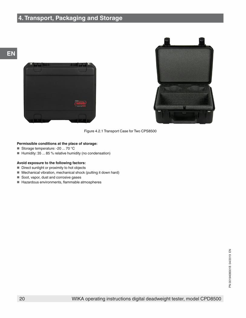
4.2.1 Transport of Measuring Heads CPS8500There is a smaller case (figure 4.2.1) to support the transport of up to two measuring heads for the CPD8500. This case also provides an option to add measuring head specific accessories.
6
7
8
4. Transport, Packaging and Storage
6
20 WIKA operating instructions digital deadweight tester, model CPD8500
PN 0
0194
0800
1B 0
4/20
19 E
N
EN
Figure 4.2.1 Transport Case for Two CPS8500
Permissible conditions at the place of storage: ■ Storage temperature: -20 ... 70 °C ■ Humidity: 35 ... 85 % relative humidity (no condensation)
Avoid exposure to the following factors: ■ Direct sunlight or proximity to hot objects ■ Mechanical vibration, mechanical shock (putting it down hard) ■ Soot, vapor, dust and corrosive gases ■ Hazardous environments, flammable atmospheres
4. Transport, Packaging and Storage
21WIKA operating instructions digital deadweight tester, model CPD8500
PN 0
0194
0800
1B 0
4/20
19 E
N
EN
5. Installation
Personnel: Skilled electrical and mechanical personnelThe following instructions must be followed in setting up the instrument for the first and any time after transporting to a different location
WARNING!READ THESE INSTRUCTIONS BEFORE INSTALLATION!
WARNING!Physical injuries and damage to property and the environment caused by hazardous mediaUpon contact with hazardous media (e.g. oxygen, acetylene, flammable or toxic substances), harmful media (e.g. corrosive, toxic, carcinogenic, radioactive), and also with refrigeration plants and compressors, there is a danger of physical injuries and damage to property and the environment.Should a failure occur, aggressive media with extremely high temperature and under high pressure or vacuum may be present at the instrument.
▶ For these media, in addition to all standard regulations, the appropriate existing codes or regulations must also be followed.
▶ Wear the requisite protective equipment (see chapter 3.6 “Personal protective equipment”).
CAUTIONDamage to the instrument When working on open electrical circuits (printed circuit boards) there is a risk of damaging sensitive electronic components through electrostatic discharge.
▶ The correct use of grounded working surfaces and personal armbands is required.
5.1 MountingThe Base must be set up on a solid, stable and level desk top surface. To assure stability and accuracy, avoid mounting the instrument on surfaces subject to motor or machinery vibration and far away from doors, windows, heating systems and air conditioning vents.
CAUTIONAvoid any vibrations and direct solar rays. Any significant temperature fluctuations would make the instrument unstable. Do not use the CPD8500 in explosive atmospheres, permanently humid or dusty environments.
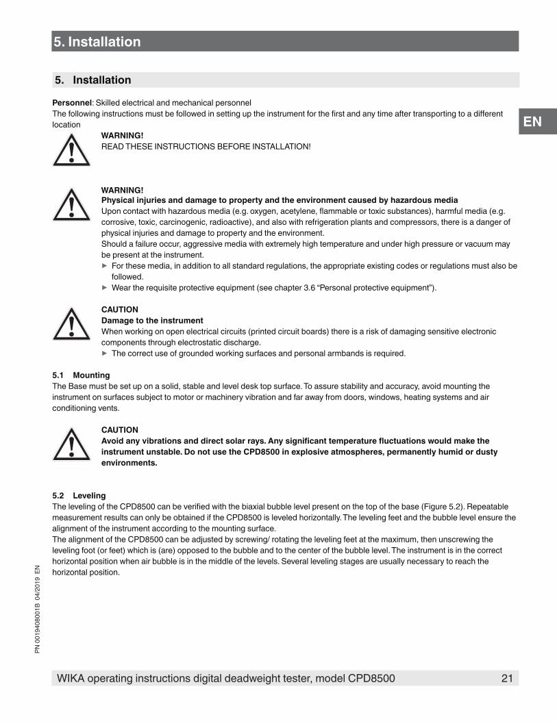
5.2 LevelingThe leveling of the CPD8500 can be verified with the biaxial bubble level present on the top of the base (Figure 5.2). Repeatable measurement results can only be obtained if the CPD8500 is leveled horizontally. The leveling feet and the bubble level ensure the alignment of the instrument according to the mounting surface. The alignment of the CPD8500 can be adjusted by screwing/ rotating the leveling feet at the maximum, then unscrewing the leveling foot (or feet) which is (are) opposed to the bubble and to the center of the bubble level. The instrument is in the correct horizontal position when air bubble is in the middle of the levels. Several leveling stages are usually necessary to reach the horizontal position.
5. Installation
22 WIKA operating instructions digital deadweight tester, model CPD8500
PN 0
0194
0800
1B 0
4/20
19 E
N
EN
Leveling feet
Bubble level
Figure 5.2
5.3 CPS8500 Measuring Head InstallationThe head installation instructions vary depending on the type of measuring head and the corresponding base of the CPD8500.
All the tools and components including hex screwdriver and base push rod are part of the accessory kit of the instrument. The details on these components can be found in Section 11.3 Absolute Accessory Kit and Section 11.5 Gauge Accessory Kit.
5.3.1 Absolute Measuring HeadThese instructions are valid for the absolute heads to be installed on an absolute base:
Wear clean and protective gloves!Before removing the protective cap from the measurement head and base, wear gloves to protect and ensure uncontaminated use.
■ Remove the white protective cap from the top of the base and the bottom of the measuring head (Figure 5.3.1-A shows the head with an isolation valve attached) by inverting the measuring head such that the protective cap is on top and then unscrewing three hex screws. The measuring head are shown in Figure 5.3.1-B with its top cover removed.
CAUTIONThe head must be placed with the protective cap on top to ensure that the piston doesn’t fall out of the cylinder.
5. Installation

23WIKA operating instructions digital deadweight tester, model CPD8500
PN 0
0194
0800
1B 0
4/20
19 E
N
EN
Protective cap
Figure 5.3.1-A Measurement Head with Top Cap
Ball bearing
Push-rod bearing
Figure 5.3.1-B Measuring Head without Top Cap
■ Remove the white protective cap from the base of the instrument by removing the hex screws (Figure 5.3.1-C) and install the push rod on the base. The push rod must be installed with the ball side towards the base. After removing the protective cap, note the position of the ball bearing equipped with the piston head. This ball bearing is designed to drive the piston in rotation. The base of the instrument has a machined slot to receive this ball bearing (Figure 5.3.1-D). Align the head such that the ball bearing on the head is in line with the machined slot on the base.
Machined slot to re-ceive ball bearing`
Figure 5.3.1-C Protective cap on Base Figure 5.3.1-D Machined slot in Base
5. Installation

24 WIKA operating instructions digital deadweight tester, model CPD8500
PN 0
0194
0800
1B 0
4/20
19 E
N
EN
■ After visually aligning the head such that the ball bearing on the head matches the corresponding slot in base, place a finger on the tip of the piston head to prevent it from dropping (Figure 5.3.1-E). Insert carefully the ball bearing in the matching slot and gently move your finger away while sliding the measuring head into the base (Figure 5.3.1-F). Secure the measuring head on to the head by screwing in the three hex screws (Figure 5.3.1-G).
Figure 5.3.1-E Aligning Head with Base
Figure 5.3.1-F Head attached to base Figure 5.3.1-G Tighten screws on Head
CAUTION!Always exert great care during this operation to prevent piston from dropping. Do not install the measuring head on the base when the motor is turned on.
5.3.2 Gauge Measuring HeadThese instructions are valid for gauge heads to be installed on gauge bases.
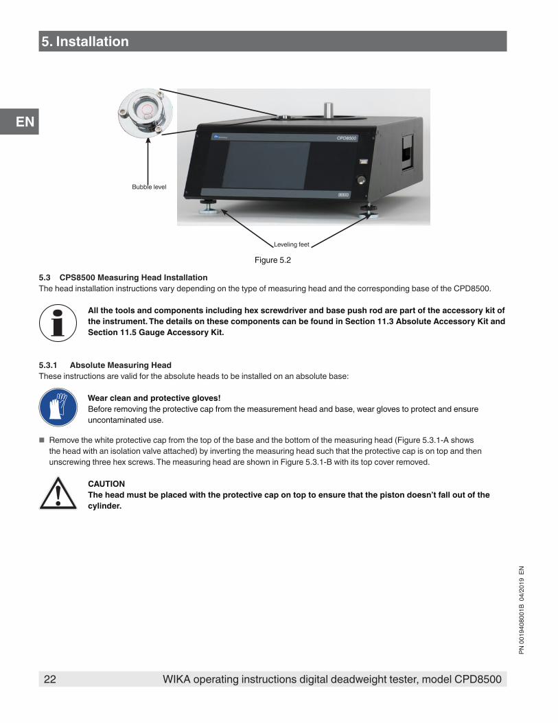
■ Remove the white protective cap from the bottom of the measuring head by inverting the measuring head such that the protective cap is on top and then unscrewing three hex screws. The measuring head are shown in Figure 5.3.2-A with its top cover removed.
5. Installation
25WIKA operating instructions digital deadweight tester, model CPD8500
PN 0
0194
0800
1B 0
4/20
19 E
N
EN
Figure 5.3.2-A Gauge Head without top cap
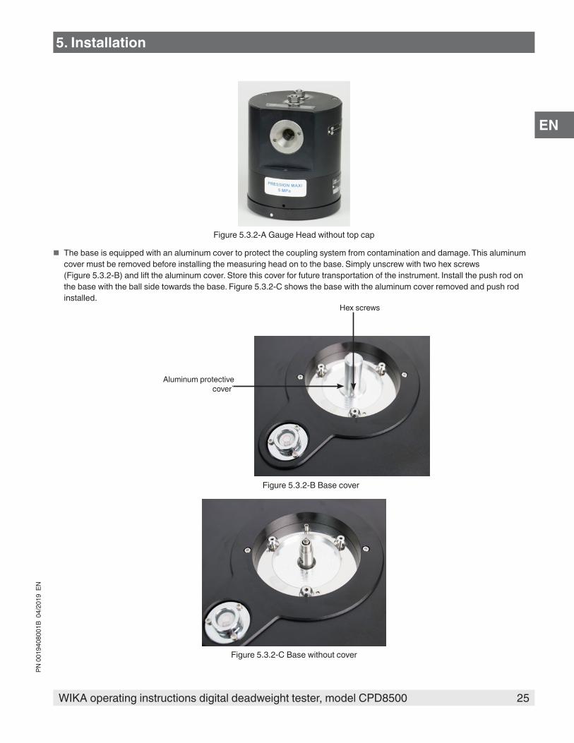
■ The base is equipped with an aluminum cover to protect the coupling system from contamination and damage. This aluminum cover must be removed before installing the measuring head on to the base. Simply unscrew with two hex screws (Figure 5.3.2-B) and lift the aluminum cover. Store this cover for future transportation of the instrument. Install the push rod on the base with the ball side towards the base. Figure 5.3.2-C shows the base with the aluminum cover removed and push rod installed.
Aluminum protective cover`
Hex screws
Figure 5.3.2-B Base cover
Figure 5.3.2-C Base without cover
5. Installation
26 WIKA operating instructions digital deadweight tester, model CPD8500
PN 0
0194
0800
1B 0
4/20
19 E
N
EN
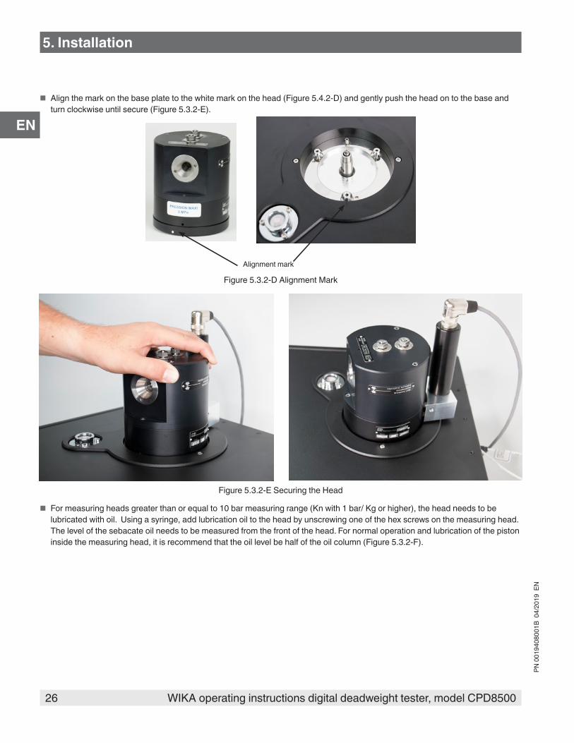
■ Align the mark on the base plate to the white mark on the head (Figure 5.4.2-D) and gently push the head on to the base and turn clockwise until secure (Figure 5.3.2-E).
Alignment mark
Figure 5.3.2-D Alignment Mark
Figure 5.3.2-E Securing the Head
■ For measuring heads greater than or equal to 10 bar measuring range (Kn with 1 bar/ Kg or higher), the head needs to be lubricated with oil. Using a syringe, add lubrication oil to the head by unscrewing one of the hex screws on the measuring head. The level of the sebacate oil needs to be measured from the front of the head. For normal operation and lubrication of the piston inside the measuring head, it is recommend that the oil level be half of the oil column (Figure 5.3.2-F).
5. Installation

27WIKA operating instructions digital deadweight tester, model CPD8500
PN 0
0194
0800
1B 0
4/20
19 E
N
EN
Figure 5.3.2-F Adding Oil to the Gauge Head
The piston lubrication oil recommended for measuring heads with Kn 1 or 2 bar/ Kg is Drosera. Sebacate oil must be used for measuring heads with higher Kn.
5.4 Head Temperature Probe InstallationThe head temperature probe is installed on the measuring head to ensure stable head temperature during operation along with temperature variation feedback to the base for accurate pressure calculation. Simply insert the head temperature probe into the probe slot placed on one side of the measuring head. Figure 5.5-B shows the probe connected to the head. The electrical connection for the probe is done by the rear panel of the CPD8500. See Section 5.7 Rear Panel for more details.
5. Installation
28 WIKA operating instructions digital deadweight tester, model CPD8500
PN 0
0194
0800
1B 0
4/20
19 E
N
EN
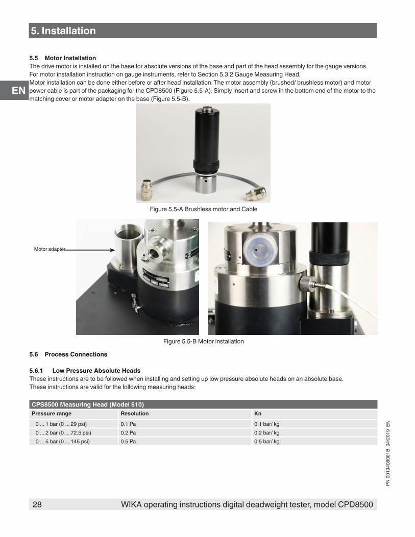
5.5 Motor InstallationThe drive motor is installed on the base for absolute versions of the base and part of the head assembly for the gauge versions. For motor installation instruction on gauge instruments, refer to Section 5.3.2 Gauge Measuring Head. Motor installation can be done either before or after head installation. The motor assembly (brushed/ brushless motor) and motor power cable is part of the packaging for the CPD8500 (Figure 5.5-A). Simply insert and screw in the bottom end of the motor to the matching cover or motor adapter on the base (Figure 5.5-B).
Figure 5.5-A Brushless motor and Cable
Motor adapter
Figure 5.5-B Motor installation
5.6 Process Connections
5.6.1 Low Pressure Absolute HeadsThese instructions are to be followed when installing and setting up low pressure absolute heads on an absolute base. These instructions are valid for the following measuring heads:
CPS8500 Measuring Head (Model 610)Pressure range Resolution Kn
0 ... 1 bar (0 ... 29 psi) 0.1 Pa 0.1 bar/ kg0 ... 2 bar (0 ... 72.5 psi) 0.2 Pa 0.2 bar/ kg0 ... 5 bar (0 ... 145 psi) 0.5 Pa 0.5 bar/ kg
5. Installation

29WIKA operating instructions digital deadweight tester, model CPD8500
PN 0
0194
0800
1B 0
4/20
19 E
N
EN
Figure 5.6.1 displays the pressure connections required to setup and operate the low pressure absolute CPD8500. All the valves and tubing involved in the setup process are part of the low pressure absolute CPD8500 carrying case. Following is a list of the accessories needed:
■ Two flex DN16 vacuum tubes ■ Three DN16 valves ■ Eight DN16 clamps ■ 0.01 micron filter and adapter ■ Vacuum pump ■ DN16 to 7/16” SAE female adapter
Remove the cover from the pressure ports on the side of the measuring head. Connect one side of the pressure ports using DN16 clamps to the measuring head vacuum isolation valve 3 followed by the filter 4Connect the vacuum isolation valve 2 to the other side of the measuring head using the clamps. Secure a vacuum tube with the clamp on the vacuum isolation valve. Clamp the open end of the vacuum tube to the rear panel pressure reference port of the instrument. See Figure 5.7-B for rear panel connections. Connect the device under test isolation valve 1 to the top pressure port of the measuring head using another DN16 clamp. The DUT must be connected to this port. The vacuum reference supply is required for zeroing and absolute mode operation of the instrument. A vacuum pump must be connected to the open pressure reference port present in the rear panel (Figure 5.7). If the vacuum pump is not connected to the open pressure reference port, the instrument would work in gauge mode.
The isolation valves need to be opened and closed for specific operation purposes. The direction of rotation of each valve must be observed physically on each valve.
5
1
2
3
4
Figure 5.6.1 Low Pressure Absolute Pressure Connections1 Device under test isolation valve 4 Sub micron filter
2 Reference vacuum isolation valve 5 Connection to rear panel vacuum reference port
3 Measuring head vacuum isolation valve
5. Installation

30 WIKA operating instructions digital deadweight tester, model CPD8500
PN 0
0194
0800
1B 0
4/20
19 E
N
ENWhen opening any vacuum valve, especially between vacuum and atmospheric or positive pressure, be careful to open the valve slowly to gradually allow pressure to equalize.
5.6.1.1 Zeroing & Spanning SetupThe following pressure connections (Figure 5.6.1) are required before performing a zero or span (single point calibration) for the internal load cell.
■ Isolation valves 1 & 3 must be closed to isolate the CPD8500 from atmosphere. ■ Reference vacuum isolation valve 2 must be open to apply vacuum by the vacuum pump in the reference chamber along with
the top of the measuring head. ■ Follow the instructions mentioned in Section 6.4.1.3 Zero & Section 6.4.1.4 Span to perform the Zero and Span calibration.
5.6.1.2 Operational SetupThe following pressure connections (Figure 5.6.1) are required for general operation of the instrument:
■ Reference vacuum isolation valve 2 must be closed to keep the vacuum in the reference chamber. ■ Isolation valves 3 must be opened slowly to go to atmosphere. The filter 4 will avoid dust or particulate to come inside
CPD8500 during this process. ■ Valve 1 must be opened. ■ Valve 3 must be closed. ■ The device under test should be connected to the valve 1 by the DN16 to 7/16” SAE female adapter.
5.6.2 High Pressure Absolute HeadsThese instructions are to be followed when installing and setting up high pressure absolute heads on an absolute base. These instructions are valid for the following measuring heads:
CPS8500 Measuring Head (Model 610)Pressure range Resolution Kn
0 ... 10 bar (0 ... 145 psi) 1 Pa 1 bar/ kg0 ... 20 bar (0 ... 290 psi) 2 Pa 2 bar/ kg
Figure 5.6.2 displays the pressure connections required to setup and zero the high pressure absolute CPD8500. All the valves and tubing involved in the setup process are part of the low pressure absolute CPD8500 carrying case. Following is a list of the accessories needed:
■ Two flex DN16 vacuum tubes ■ One DN16 valve ■ T-fitting DN16 clamps ■ DN16 to 7/16” SAE female adapter
The device under test connects to the measuring head from the top using a t-fitting clamp. Clamp one end of the vacuum tube to the vacuum isolation valve and connect it to the rear panel pressure reference port of the instrument with one more clamp. For performing a zero or span (Section 6.4.1.4 Span), the device under test is disconnected and the other end of the vacuum tube is connected to the t-fitting clamp (Figure 5.6.2). The vacuum reference supply is required for zeroing and absolute mode operation of the instrument. A vacuum pump must be connected to the open pressure reference port present in the rear panel (Figure 5.7).
5. Installation
31WIKA operating instructions digital deadweight tester, model CPD8500
PN 0
0194
0800
1B 0
4/20
19 E
N
EN1
2
3
4
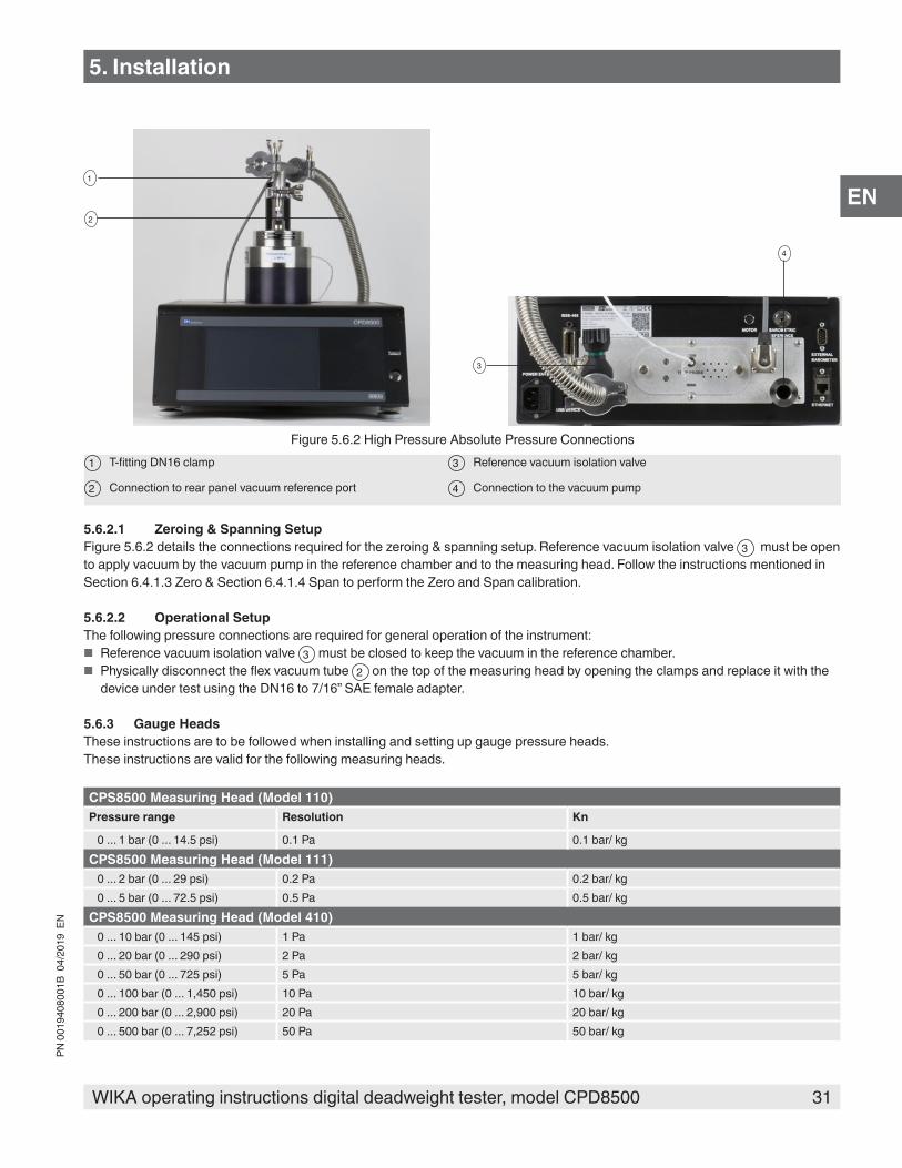
Figure 5.6.2 High Pressure Absolute Pressure Connections1 T-fitting DN16 clamp 3 Reference vacuum isolation valve
2 Connection to rear panel vacuum reference port 4 Connection to the vacuum pump
5.6.2.1 Zeroing & Spanning SetupFigure 5.6.2 details the connections required for the zeroing & spanning setup. Reference vacuum isolation valve 3 must be open to apply vacuum by the vacuum pump in the reference chamber and to the measuring head. Follow the instructions mentioned in Section 6.4.1.3 Zero & Section 6.4.1.4 Span to perform the Zero and Span calibration. 5.6.2.2 Operational SetupThe following pressure connections are required for general operation of the instrument:
■ Reference vacuum isolation valve 3 must be closed to keep the vacuum in the reference chamber. ■ Physically disconnect the flex vacuum tube 2 on the top of the measuring head by opening the clamps and replace it with the
device under test using the DN16 to 7/16” SAE female adapter.
5.6.3 Gauge HeadsThese instructions are to be followed when installing and setting up gauge pressure heads. These instructions are valid for the following measuring heads.
CPS8500 Measuring Head (Model 110)Pressure range Resolution Kn
0 ... 1 bar (0 ... 14.5 psi) 0.1 Pa 0.1 bar/ kgCPS8500 Measuring Head (Model 111)
0 ... 2 bar (0 ... 29 psi) 0.2 Pa 0.2 bar/ kg0 ... 5 bar (0 ... 72.5 psi) 0.5 Pa 0.5 bar/ kg
CPS8500 Measuring Head (Model 410)0 ... 10 bar (0 ... 145 psi) 1 Pa 1 bar/ kg0 ... 20 bar (0 ... 290 psi) 2 Pa 2 bar/ kg0 ... 50 bar (0 ... 725 psi) 5 Pa 5 bar/ kg0 ... 100 bar (0 ... 1,450 psi) 10 Pa 10 bar/ kg0 ... 200 bar (0 ... 2,900 psi) 20 Pa 20 bar/ kg0 ... 500 bar (0 ... 7,252 psi) 50 Pa 50 bar/ kg
5. Installation
32 WIKA operating instructions digital deadweight tester, model CPD8500
PN 0
0194
0800
1B 0
4/20
19 E
N
EN
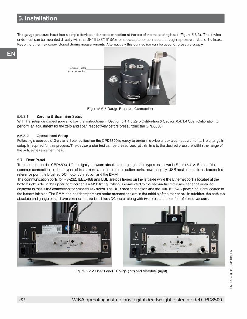
The gauge pressure head has a simple device under test connection at the top of the measuring head (Figure 5.6.3). The device under test can be mounted directly with the DN16 to 7/16” SAE female adapter or connected through a pressure tube to the head. Keep the other hex screw closed during measurements. Alternatively this connection can be used for pressure supply.
Device under test connection
Figure 5.6.3 Gauge Pressure Connections
5.6.3.1 Zeroing & Spanning SetupWith the setup described above, follow the instructions in Section 6.4.1.3 Zero Calibration & Section 6.4.1.4 Span Calibration to perform an adjustment for the zero and span respectively before pressurizing the CPD8500.
5.6.3.2 Operational SetupFollowing a successful Zero and Span calibration the CPD8500 is ready to perform device under test measurements. No change in setup is required for this process. The device under test can be pressurized at this time to the desired pressure within the range of the active measurement head.
5.7 Rear PanelThe rear panel of the CPD8500 differs slightly between absolute and gauge base types as shown in Figure 5.7-A. Some of the common connections for both types of instruments are the communication ports, power supply, USB host connections, barometric reference port, the brushed DC motor connection and the EMM. The communication ports for RS-232, IEEE-488 and USB are positioned on the left side while the Ethernet port is located at the bottom right side. In the upper right corner is a M12 fitting , which is connected to the barometric reference sensor if installed, adjacent to that is the connection for brushed DC motor. The USB host connection and the 100-120 VAC power input are located at the bottom left side. The EMM and head temperature probe connections are in the middle of the rear panel. In addition, the both the absolute and gauge bases have connections for brushless DC motor along with two pressure ports for reference vacuum.
Figure 5.7-A Rear Panel - Gauge (left) and Absolute (right)
5. Installation
33WIKA operating instructions digital deadweight tester, model CPD8500
PN 0
0194
0800
1B 0
4/20
19 E
N
EN4
1
3
15
2
14 1213
5 7 86 9
10
11
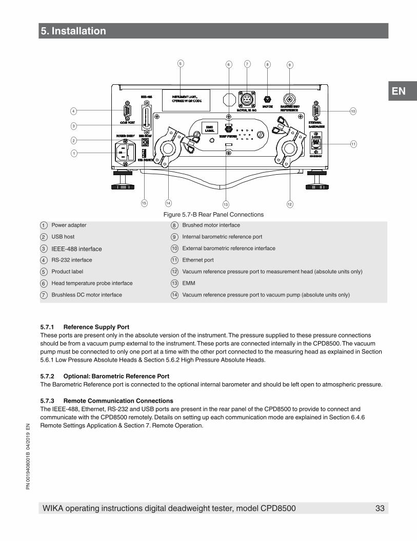
Figure 5.7-B Rear Panel Connections1 Power adapter 8 Brushed motor interface
2 USB host 9 Internal barometric reference port
3 IEEE-488 interface 10 External barometric reference interface
4 RS-232 interface 11 Ethernet port
5 Product label 12 Vacuum reference pressure port to measurement head (absolute units only)
6 Head temperature probe interface 13 EMM
7 Brushless DC motor interface 14 Vacuum reference pressure port to vacuum pump (absolute units only)
5.7.1 Reference Supply PortThese ports are present only in the absolute version of the instrument. The pressure supplied to these pressure connections should be from a vacuum pump external to the instrument. These ports are connected internally in the CPD8500. The vacuum pump must be connected to only one port at a time with the other port connected to the measuring head as explained in Section 5.6.1 Low Pressure Absolute Heads & Section 5.6.2 High Pressure Absolute Heads.
5.7.2 Optional: Barometric Reference PortThe Barometric Reference port is connected to the optional internal barometer and should be left open to atmospheric pressure.
5.7.3 Remote Communication ConnectionsThe IEEE-488, Ethernet, RS-232 and USB ports are present in the rear panel of the CPD8500 to provide to connect and communicate with the CPD8500 remotely. Details on setting up each communication mode are explained in Section 6.4.6 Remote Settings Application & Section 7. Remote Operation.
5. Installation
34 WIKA operating instructions digital deadweight tester, model CPD8500
PN 0
0194
0800
1B 0
4/20
19 E
N
EN
6. Operation
6.1 General OperationThis section describes the procedures for operating the CPD8500 from the front panel. By following the procedures you can expect your CPD8500 to deliver maximum accuracy and dependability for many years of useful service.
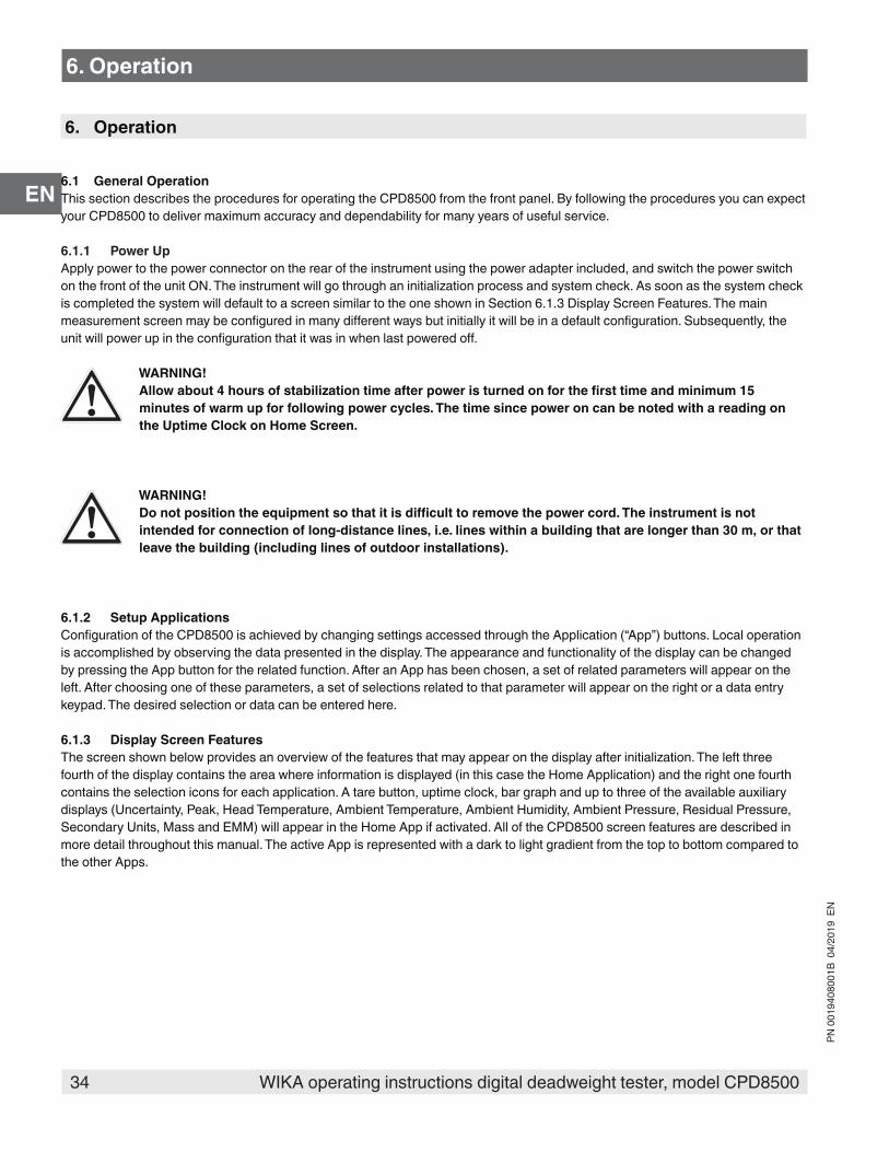
6.1.1 Power UpApply power to the power connector on the rear of the instrument using the power adapter included, and switch the power switch on the front of the unit ON. The instrument will go through an initialization process and system check. As soon as the system check is completed the system will default to a screen similar to the one shown in Section 6.1.3 Display Screen Features. The main measurement screen may be configured in many different ways but initially it will be in a default configuration. Subsequently, the unit will power up in the configuration that it was in when last powered off.
WARNING!Allow about 4 hours of stabilization time after power is turned on for the first time and minimum 15 minutes of warm up for following power cycles. The time since power on can be noted with a reading on the Uptime Clock on Home Screen.
WARNING!Do not position the equipment so that it is difficult to remove the power cord. The instrument is not intended for connection of long-distance lines, i.e. lines within a building that are longer than 30 m, or that leave the building (including lines of outdoor installations).
6.1.2 Setup ApplicationsConfiguration of the CPD8500 is achieved by changing settings accessed through the Application (“App”) buttons. Local operation is accomplished by observing the data presented in the display. The appearance and functionality of the display can be changed by pressing the App button for the related function. After an App has been chosen, a set of related parameters will appear on the left. After choosing one of these parameters, a set of selections related to that parameter will appear on the right or a data entry keypad. The desired selection or data can be entered here.
6.1.3 Display Screen FeaturesThe screen shown below provides an overview of the features that may appear on the display after initialization. The left three fourth of the display contains the area where information is displayed (in this case the Home Application) and the right one fourth contains the selection icons for each application. A tare button, uptime clock, bar graph and up to three of the available auxiliary displays (Uncertainty, Peak, Head Temperature, Ambient Temperature, Ambient Humidity, Ambient Pressure, Residual Pressure, Secondary Units, Mass and EMM) will appear in the Home App if activated. All of the CPD8500 screen features are described in more detail throughout this manual. The active App is represented with a dark to light gradient from the top to bottom compared to the other Apps.
6. Operation

35WIKA operating instructions digital deadweight tester, model CPD8500
PN 0
0194
0800
1B 0
4/20
19 E
N
EN
6. Operation
Operating Screen Settings Apps
Active Head InformationZero, Span or Optional Tare
Current Pressure Value Optional Bar graph
Units / Pressure Type
Auxiliary Displays {
Motor Status Icon Uptime Clock
Figure 6.1.2 Display Screen Features

36 WIKA operating instructions digital deadweight tester, model CPD8500
PN 0
0194
0800
1B 0
4/20
19 E
N
EN
6.2 Initial SetupSection 6.2.1 Local Gravity Setup and Section 6.2.2 Contact and Version Information Application are provided first so that the operator can initially check the information screen to verify the installed components and to change the language if needed.6.2.1 Local Gravity SetupThe CPD8500 uses local gravity as part of the internal calculation to deliver an accurate pressure value. Upon power up, the local gravity prompt appears on the right side of the screen (Figure 6.2.1 Local Gravity Setup). The user could setup the local gravity by clicking [ ] and then navigating to the Service Application (Section 6.4.9 Service Application). Further details on setting local gravity is mentioned in Section 8.2.9 Reference Level.
Figure 6.2.1 Local Gravity Setup
6.2.2 Contact and Version Information Application
Press the Information App button [ ] to display Mensor contact, active head information, installed environmental monitoring module along with instrument and software version information. Information on optional sensors such as the internal barometer and a vacuum sensor can also be found here.
Figure 6.2.2 Information
6. Operation
37WIKA operating instructions digital deadweight tester, model CPD8500
PN 0
0194
0800
1B 0
4/20
19 E
N
EN
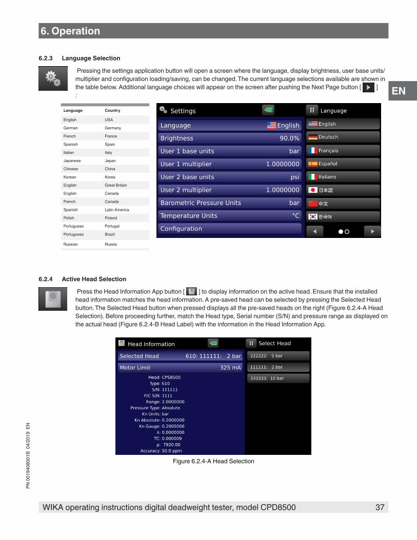
6.2.3 Language Selection
Pressing the settings application button will open a screen where the language, display brightness, user base units/multiplier and configuration loading/saving, can be changed. The current language selections available are shown in the table below. Additional language choices will appear on the screen after pushing the Next Page button [ ]:
Language Country
English USA
German Germany
French France
Spanish Spain
Italian Italy
Japanese Japan
Chinese China
Korean Korea
English Great Britain
English Canada
French Canada
Spanish Latin America
Polish Poland
Portuguese Portugal
Portuguese Brazil
Russian Russia
6.2.4 Active Head Selection
Press the Head Information App button [ ] to display information on the active head. Ensure that the installed head information matches the head information. A pre-saved head can be selected by pressing the Selected Head button. The Selected Head button when pressed displays all the pre-saved heads on the right (Figure 6.2.4-A Head Selection). Before proceeding further, match the Head type, Serial number (S/N) and pressure range as displayed on the actual head (Figure 6.2.4-B Head Label) with the information in the Head Information App.
Figure 6.2.4-A Head Selection
6. Operation
38 WIKA operating instructions digital deadweight tester, model CPD8500
PN 0
0194
0800
1B 0
4/20
19 E
N
EN
Head type and Serial number
Figure 6.2.4-B Head Label
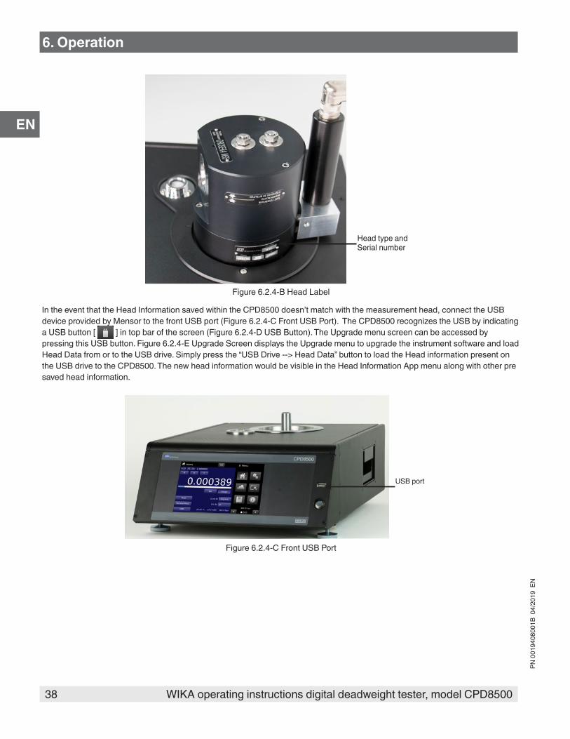
In the event that the Head Information saved within the CPD8500 doesn’t match with the measurement head, connect the USB device provided by Mensor to the front USB port (Figure 6.2.4-C Front USB Port). The CPD8500 recognizes the USB by indicating a USB button [ ] in top bar of the screen (Figure 6.2.4-D USB Button). The Upgrade menu screen can be accessed by pressing this USB button. Figure 6.2.4-E Upgrade Screen displays the Upgrade menu to upgrade the instrument software and load Head Data from or to the USB drive. Simply press the “USB Drive --> Head Data” button to load the Head information present on the USB drive to the CPD8500. The new head information would be visible in the Head Information App menu along with other pre saved head information.
USB port
Figure 6.2.4-C Front USB Port
6. Operation

39WIKA operating instructions digital deadweight tester, model CPD8500
PN 0
0194
0800
1B 0
4/20
19 E
N
EN
USB button
Figure 6.2.4-D USB Button
Figure 6.2.4-E Upgrade Screen
6.2.5 Head Motor ActivationThe motor status icon appears on the top bar of the screen and is visible to the user in any App. By default the motor icon is black [ ] in color to indicate that the motor is off and the piston-cylinder inside measuring head is not spinning. The motor can be turned on by clicking the motor icon, this temporarily freezes the icon to indicate the step up process for the motor before changing the color of the motor to green [ ], indicating an active motor spinning the piston-cylinder. The motor should be turned on while operating and performing calibration functions with the CPD8500. The motor status icon turns yellow [ ] to indicate a warning or an error in spinning the piston-cylinder. The details on the error can be noted in the Troubleshooting App.
6. Operation
40 WIKA operating instructions digital deadweight tester, model CPD8500
PN 0
0194
0800
1B 0
4/20
19 E
N
EN
6. Operation
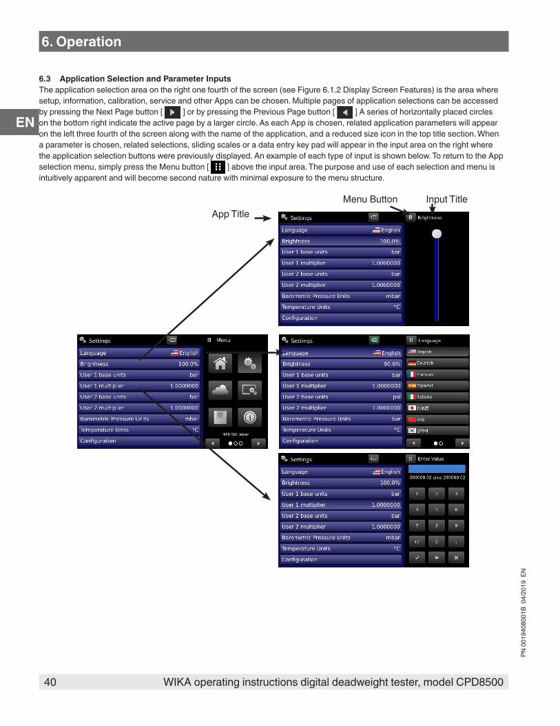
6.3 Application Selection and Parameter InputsThe application selection area on the right one fourth of the screen (see Figure 6.1.2 Display Screen Features) is the area where setup, information, calibration, service and other Apps can be chosen. Multiple pages of application selections can be accessed by pressing the Next Page button [ ] or by pressing the Previous Page button [ ] A series of horizontally placed circles on the bottom right indicate the active page by a larger circle. As each App is chosen, related application parameters will appear on the left three fourth of the screen along with the name of the application, and a reduced size icon in the top title section. When a parameter is chosen, related selections, sliding scales or a data entry key pad will appear in the input area on the right where the application selection buttons were previously displayed. An example of each type of input is shown below. To return to the App selection menu, simply press the Menu button [ ] above the input area. The purpose and use of each selection and menu is intuitively apparent and will become second nature with minimal exposure to the menu structure.
Menu ButtonApp Title
Input Title

41WIKA operating instructions digital deadweight tester, model CPD8500
PN 0
0194
0800
1B 0
4/20
19 E
N
EN
6.4 Applications6.4.1 Home Applications
The Home App is the normal operation screen. This application is different from the others in that it is not used to setup the configuration but is used to monitor the pressure applied to the current head.
The screen in Figure 6.4.1-A Basic Home App shows the basic Home App in an instrument. The user can change the display to show an uptime clock indicating time since power on, a bar graph corresponding to the range of the head, a Tare button and multiple auxiliary displays by pressing the auxiliary buttons on the left corner of the screen (Figure 6.4.1-B Home App with all Features). The Zero, Span and Units button are always displayed. When the Units button is pressed a selection of imperial and metric units will be displayed on the right (Figure 6.4.1-C Pressure Units). Additional icons representing the status of the instrument may appear adjacent to the Tare button during operation (Table 6.4.1 Internal Status Icons).
Figure 6.4.1-A Basic Home App
Figure 6.4.1-B Home App with all Features Figure 6.4.1-C Pressure Units
6. Operation

42 WIKA operating instructions digital deadweight tester, model CPD8500
PN 0
0194
0800
1B 0
4/20
19 E
N
EN
Table 6.4.1 Internal Status Icons
Icon DesriptionPressure reading unstable
Internal load cell busy
EMM parameters outside stable window
6.4.1.1 Current Pressure ReadingThe current pressure reading is displayed in the Home App at all times. The pressure reading can appear either gray, white or green in color indicating invalid, unstable or stable pressure values respectively (Figure 6.4.1.1-A Invalid Pressure Reading).
Figure 6.4.1.1-A Invalid Pressure Reading
Figure 6.4.1.1-B Unstable Pressure Reading Figure 6.4.1.1-C Stable Pressure Reading
6. Operation

43WIKA operating instructions digital deadweight tester, model CPD8500
PN 0
0194
0800
1B 0
4/20
19 E
N
EN
6. Operation
6.4.1.2 Units and Pressure TypeThe Units button is always displayed. When the units button is pressed a selection of imperial and metric units will be displayed on the right (Figure 6.4.1.2-A). The units menu is categorized by Imperial and Metric units. Further pressure units of each category can be navigated by the page forward [ ] and backward [ ] keys. The current pressure type is displayed by the Pressure Type button in the Home App. When an optional internal/ external barometric reference is installed, the native gauge instrument can emulate absolute pressure using the barometric reference. However for a native absolute instrument with an absolute base and an absolute head, the instrument can work in either gauge or absolute mode depending on the rear panel reference port connection. If the pressure reference port is left open to the atmosphere, the instrument measures gauge pressure, alternatively if the reference port is connected to a vacuum pump, the instrument can only measure absolute pressures. Both emulation and native pressure type can be activated simply by pressing the Pressure Type button. The emulation pressure type is highlighted in gold to distinguish from the native mode (Figure 6.4.1.2-B)
Pressure Units button
Figure 6.4.1.2-A Pressure units
Pressure Type button
Figure 6.4.1.2-B Pressure Type (Emulated)
6.4.1.3 ZeroThe Zero button [ ] in the Home App allows the user to perform a single point calibration to adjust the zero point of the internal load cell of the instrument. The Zero calibration must be performed, if after power up, the user notices a slight drift. This drift can be attributed to a variety of reasons like temperature drifts, changes in ambient conditions, changes in leveling of the instrument and/or its location. Table 6.4.1.4 displays different scenarios requiring Zero and Span calibration.The procedure for performing the Zero calibration is different for absolute and gauge mode. Figure 6.4.1.3 Zero Button shows the Zero button in the Home App.
Zero button
Figure 6.4.1.3 Zero Button

44 WIKA operating instructions digital deadweight tester, model CPD8500
PN 0
0194
0800
1B 0
4/20
19 E
N
EN
6. Operation
WARNING!In order to obtain accurate pressure measurements, the user must check that the display indicates stable zero, before starting any measurements.
6.4.1.3.1 Zeroing in Gauge Mode or Emulated Gauge ModeThis procedure is valid only when the pressure type of the instrument is set to Gauge. This can be done for following combinations in the instrument:
■ A gauge base with a gauge head ■ An absolute base with an absolute head with vacuum reference ports open to atmosphere. ■ An absolute base with a gauge adapted absolute head
Pressing the Zero button initiates a zeroing sequence as shown by Figure 6.4.1.3.1 Zeroing in Gauge Mode. The current pressure reading turns gray during the process to indicate a non valid pressure reading. The status of the zeroing sequence is displayed on the right side of the screen. During the zeroing sequence, the status icon represents that the load cell is busy.
Figure 6.4.1.3.1 Zeroing in Gauge Mode
6.4.1.3.2 Zeroing in Absolute ModeThis procedure is valid only when the pressure type of the instrument is set to Absolute. This can be done when an absolute head is installed on an absolute base and the operation is carried out in native pressure mode. The Zero button is inaccessible (grayed) until a stable vacuum pressure is applied on the reference of the instrument and the vacuum sensor displays a value less than 20 pascals and greater than 2 pascals. Vacuum pump recommendations and connections are mentioned in Section 5. Installation.
Zero button inaccessible
Figure 6.4.1.3.2 Inaccessible Zero Button
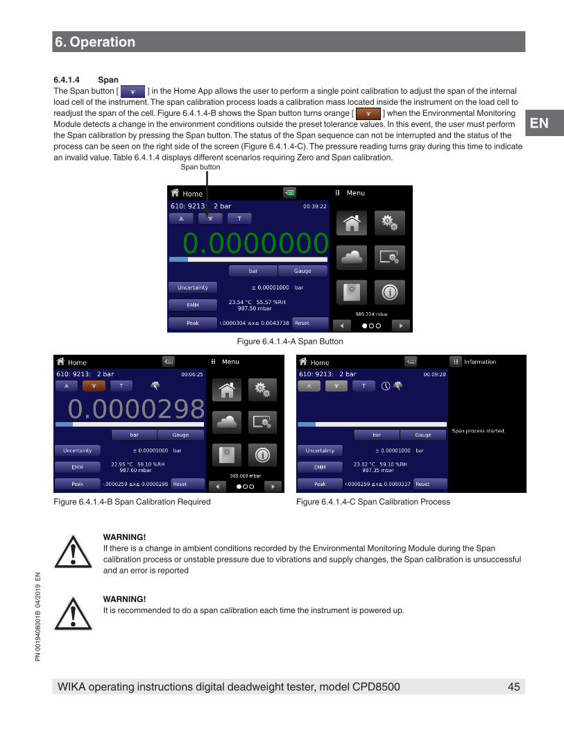
45WIKA operating instructions digital deadweight tester, model CPD8500
PN 0
0194
0800
1B 0
4/20
19 E
N
EN
6. Operation
6.4.1.4 SpanThe Span button [ ] in the Home App allows the user to perform a single point calibration to adjust the span of the internal load cell of the instrument. The span calibration process loads a calibration mass located inside the instrument on the load cell to readjust the span of the cell. Figure 6.4.1.4-B shows the Span button turns orange [ ] when the Environmental Monitoring Module detects a change in the environment conditions outside the preset tolerance values. In this event, the user must perform the Span calibration by pressing the Span button. The status of the Span sequence can not be interrupted and the status of the process can be seen on the right side of the screen (Figure 6.4.1.4-C). The pressure reading turns gray during this time to indicate an invalid value. Table 6.4.1.4 displays different scenarios requiring Zero and Span calibration.
Span button
Figure 6.4.1.4-A Span Button
Figure 6.4.1.4-B Span Calibration Required Figure 6.4.1.4-C Span Calibration Process
WARNING!If there is a change in ambient conditions recorded by the Environmental Monitoring Module during the Span calibration process or unstable pressure due to vibrations and supply changes, the Span calibration is unsuccessful and an error is reported
WARNING!It is recommended to do a span calibration each time the instrument is powered up.

46 WIKA operating instructions digital deadweight tester, model CPD8500
PN 0
0194
0800
1B 0
4/20
19 E
N
EN
6. Operation
n Condition Scenario
1 Upon first boot up May be done at any point; must be done after the initial warm-up period2 New head selected Selecting a new head data file3 Pressure type changed Changing from gauge, absolute, bidirectional modes; especially when
the pressure applied to the reference port is changed4 Head Temperature Probe out of tolerance Tolerance limits settable in Limits application5 Ambient Pressure out of tolerance Tolerance limits settable in Limits application6 Ambient Temperature out of tolerance Tolerance limits settable in Limits application7 Relative humidity out of tolerance Tolerance limits settable in Limits application
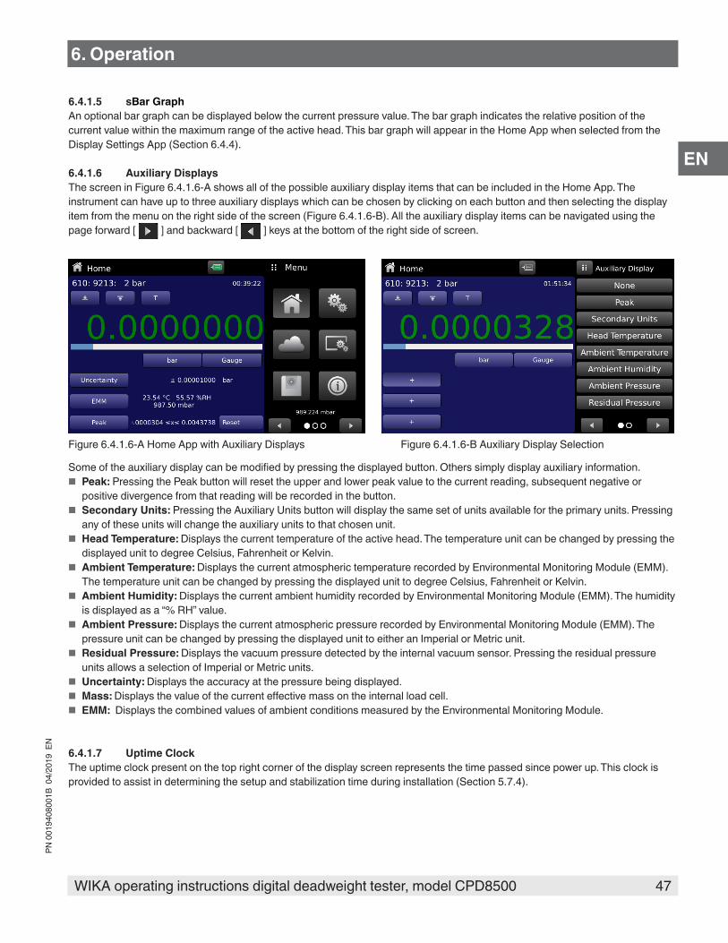
47WIKA operating instructions digital deadweight tester, model CPD8500
PN 0
0194
0800
1B 0
4/20
19 E
N
EN
6. Operation
6.4.1.5 sBar GraphAn optional bar graph can be displayed below the current pressure value. The bar graph indicates the relative position of the current value within the maximum range of the active head. This bar graph will appear in the Home App when selected from the Display Settings App (Section 6.4.4).
6.4.1.6 Auxiliary DisplaysThe screen in Figure 6.4.1.6-A shows all of the possible auxiliary display items that can be included in the Home App. The instrument can have up to three auxiliary displays which can be chosen by clicking on each button and then selecting the display item from the menu on the right side of the screen (Figure 6.4.1.6-B). All the auxiliary display items can be navigated using the page forward [ ] and backward [ ] keys at the bottom of the right side of screen.
Figure 6.4.1.6-A Home App with Auxiliary Displays Figure 6.4.1.6-B Auxiliary Display Selection
Some of the auxiliary display can be modified by pressing the displayed button. Others simply display auxiliary information. ■ Peak: Pressing the Peak button will reset the upper and lower peak value to the current reading, subsequent negative or
positive divergence from that reading will be recorded in the button. ■ Secondary Units: Pressing the Auxiliary Units button will display the same set of units available for the primary units. Pressing
any of these units will change the auxiliary units to that chosen unit. ■ Head Temperature: Displays the current temperature of the active head. The temperature unit can be changed by pressing the
displayed unit to degree Celsius, Fahrenheit or Kelvin. ■ Ambient Temperature: Displays the current atmospheric temperature recorded by Environmental Monitoring Module (EMM).
The temperature unit can be changed by pressing the displayed unit to degree Celsius, Fahrenheit or Kelvin. ■ Ambient Humidity: Displays the current ambient humidity recorded by Environmental Monitoring Module (EMM). The humidity
is displayed as a “% RH” value. ■ Ambient Pressure: Displays the current atmospheric pressure recorded by Environmental Monitoring Module (EMM). The
pressure unit can be changed by pressing the displayed unit to either an Imperial or Metric unit. ■ Residual Pressure: Displays the vacuum pressure detected by the internal vacuum sensor. Pressing the residual pressure
units allows a selection of Imperial or Metric units. ■ Uncertainty: Displays the accuracy at the pressure being displayed. ■ Mass: Displays the value of the current effective mass on the internal load cell. ■ EMM: Displays the combined values of ambient conditions measured by the Environmental Monitoring Module.
6.4.1.7 Uptime ClockThe uptime clock present on the top right corner of the display screen represents the time passed since power up. This clock is provided to assist in determining the setup and stabilization time during installation (Section 5.7.4).

48 WIKA operating instructions digital deadweight tester, model CPD8500
PN 0
0194
0800
1B 0
4/20
19 E
N
EN
6.4.1.8 Tare ButtonIf the Tare calibration function has been chosen in the Display Settings App (Section 6.4.4), then the Tare Button [ ] will appear in the Home screen. For safety reasons, the tare button will be highlighted in golden when active. When the Tare button is pressed, the instrument will subtract the current pressure reading (the tare pressure) so that the instrument will display zero. Subsequent deviations in pressure will be relative to the tare pressure.
Tare button
Figure 6.4.1.8 Tare Button
Pressing the tare button again will deactivate the tare and change the pressure indication back to the reading corresponding to the calibrated output of the transducer. An active tare will revert to a deactivated state after a power cycle.
6.4.1.9 Active HeadThe Home App displays basic information on the current head in the top left of the screen. This includes the Head Type, Serial Number and Pressure Range in native units. The active head can be selected in Section 6.4.5 Head Information Application.
6.4.1.10 BarometerIf an external or internal barometer is installed, the atmospheric pressure sensed by the barometer is displayed on the bottom right of the screen (Figure 6.4.1.10). The barometer units can be selected in the Section 6.4.2.4 Barometer Units.
Barometer Readout
Figure 6.4.1.10 Barometer Readout
When both the internal and external barometers are connected to the instrument. The Barometer Readout would indicate the external barometer and would utilize this to do emulated pressure measurement.
6. Operation

49WIKA operating instructions digital deadweight tester, model CPD8500
PN 0
0194
0800
1B 0
4/20
19 E
N
EN
6.4.2 Settings Application
The Settings App is used to set up general settings for the display. Settings parameters include Language, Brightness, User 1 base units, User 1 multiplier, User 2 base units, User 2 multiplier, Barometer units, and Configuration. Figure 6.4.2 Settings App shows these parameters as indicated, when the Settings App has been chosen. As each parameter is pressed, an input screen will appear on the right where selections can be made.
The Settings App provides a place to change the language, display brightness, user units, and barometer units. Configuration settings of the instrument can also be saved within this application plus the default configuration can be activated.
Figure 6.4.2 Settings App
6.4.2.1 LanguagesThe Language parameter provides a selection of different languages. Once a language is chosen all words within all menus will appear in the chosen language and the radix character (decimal mark) will change from a dot (.) to a comma (,) depending on the language chosen. More languages can be accessed by navigating to the next page of the language selection menu on the right side of the screen.
Figure 6.4.2.1 Languages
6. Operation

50 WIKA operating instructions digital deadweight tester, model CPD8500
PN 0
0194
0800
1B 0
4/20
19 E
N
EN
6.4.2.2 BrightnessThe Brightness setting provides a sliding scale to increment the screen brightness in all screens. Sliding your finger along the bar/ line to move the ball cursor or touching anywhere on the bar/line will change the brightness of the screen. After the setting is made and your finger is removed from the screen the menu will show the brightness percent selected.
Figure 6.4.2.2 Brightness
6.4.2.3 User Base Units/ Base Units MultiplierWhen choosing a unit of measure from the Home Application (main screen), standard units can be chosen in addition to two user defined units. User units 1 and 2 are defined in the Settings App using “User 1 base units”, “User 1 multiplier” and / or “User 2 base units”, “User 2 multiplier”. If the display of a special unit is needed, then a base unit should be chosen (psi, bar or Pascal) as the “User base unit” and the “User multiplier” can be entered to derive the special unit using the formula: Special unit = Base Unit x Unit multiplier. When set this way, and the user unit has been chosen from the main screen, then the user unit will now display the Special unit as derived.
Figure 6.4.2.3 User base units/ Base units multiplier
6. Operation
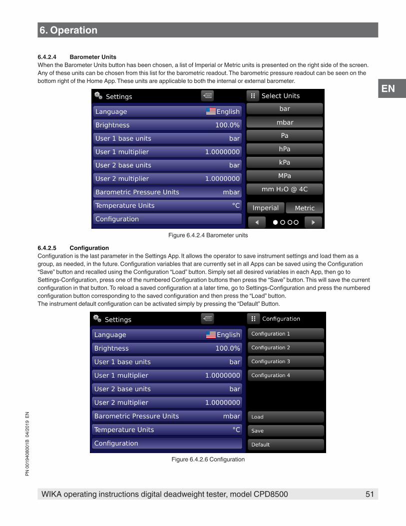
51WIKA operating instructions digital deadweight tester, model CPD8500
PN 0
0194
0800
1B 0
4/20
19 E
N
EN
6.4.2.4 Barometer UnitsWhen the Barometer Units button has been chosen, a list of Imperial or Metric units is presented on the right side of the screen. Any of these units can be chosen from this list for the barometric readout. The barometric pressure readout can be seen on the bottom right of the Home App. These units are applicable to both the internal or external barometer.
Figure 6.4.2.4 Barometer units
6.4.2.5 ConfigurationConfiguration is the last parameter in the Settings App. It allows the operator to save instrument settings and load them as a group, as needed, in the future. Configuration variables that are currently set in all Apps can be saved using the Configuration “Save” button and recalled using the Configuration “Load” button. Simply set all desired variables in each App, then go to Settings-Configuration, press one of the numbered Configuration buttons then press the “Save” button. This will save the current configuration in that button. To reload a saved configuration at a later time, go to Settings-Configuration and press the numbered configuration button corresponding to the saved configuration and then press the “Load” button.The instrument default configuration can be activated simply by pressing the “Default” Button.
Figure 6.4.2.6 Configuration
6. Operation
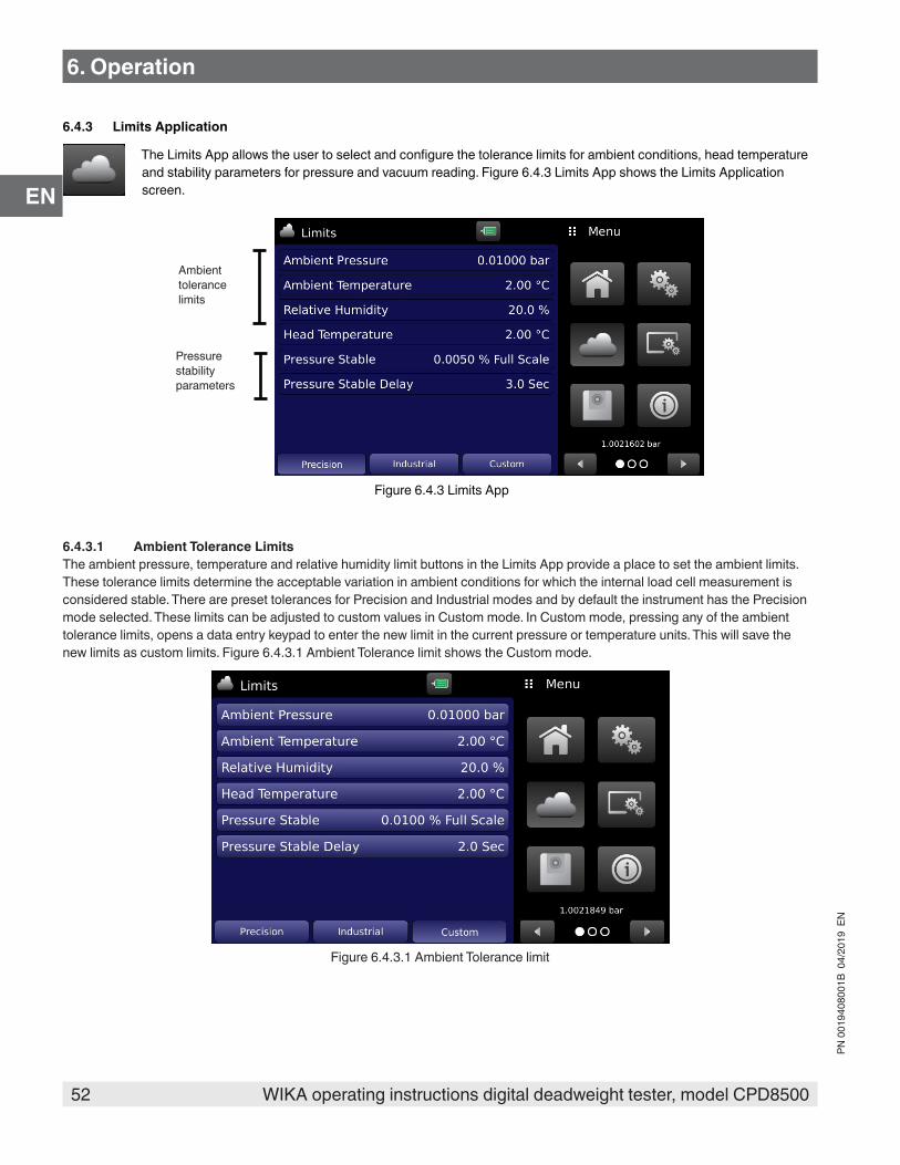
52 WIKA operating instructions digital deadweight tester, model CPD8500
PN 0
0194
0800
1B 0
4/20
19 E
N
EN
6.4.3 Limits Application
The Limits App allows the user to select and configure the tolerance limits for ambient conditions, head temperature and stability parameters for pressure and vacuum reading. Figure 6.4.3 Limits App shows the Limits Application screen.
Ambient tolerance limits
Pressure stability parameters
Figure 6.4.3 Limits App
6.4.3.1 Ambient Tolerance LimitsThe ambient pressure, temperature and relative humidity limit buttons in the Limits App provide a place to set the ambient limits. These tolerance limits determine the acceptable variation in ambient conditions for which the internal load cell measurement is considered stable. There are preset tolerances for Precision and Industrial modes and by default the instrument has the Precision mode selected. These limits can be adjusted to custom values in Custom mode. In Custom mode, pressing any of the ambient tolerance limits, opens a data entry keypad to enter the new limit in the current pressure or temperature units. This will save the new limits as custom limits. Figure 6.4.3.1 Ambient Tolerance limit shows the Custom mode.
Figure 6.4.3.1 Ambient Tolerance limit
6. Operation
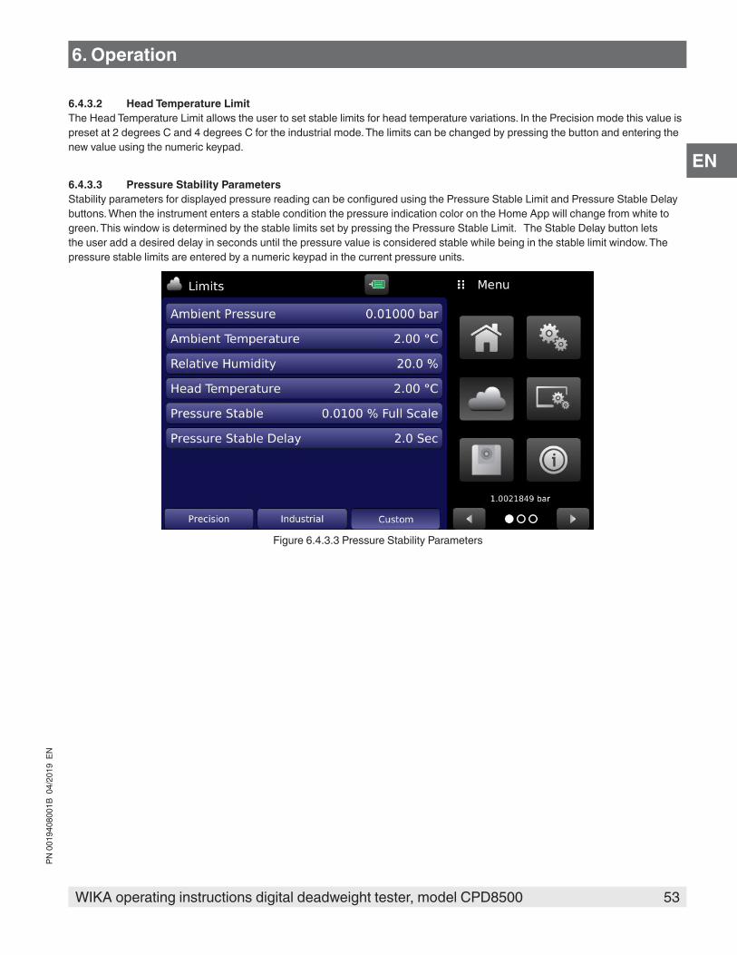
53WIKA operating instructions digital deadweight tester, model CPD8500
PN 0
0194
0800
1B 0
4/20
19 E
N
EN
6.4.3.2 Head Temperature LimitThe Head Temperature Limit allows the user to set stable limits for head temperature variations. In the Precision mode this value is preset at 2 degrees C and 4 degrees C for the industrial mode. The limits can be changed by pressing the button and entering the new value using the numeric keypad.
6.4.3.3 Pressure Stability ParametersStability parameters for displayed pressure reading can be configured using the Pressure Stable Limit and Pressure Stable Delay buttons. When the instrument enters a stable condition the pressure indication color on the Home App will change from white to green. This window is determined by the stable limits set by pressing the Pressure Stable Limit. The Stable Delay button lets the user add a desired delay in seconds until the pressure value is considered stable while being in the stable limit window. The pressure stable limits are entered by a numeric keypad in the current pressure units.
Figure 6.4.3.3 Pressure Stability Parameters
6. Operation
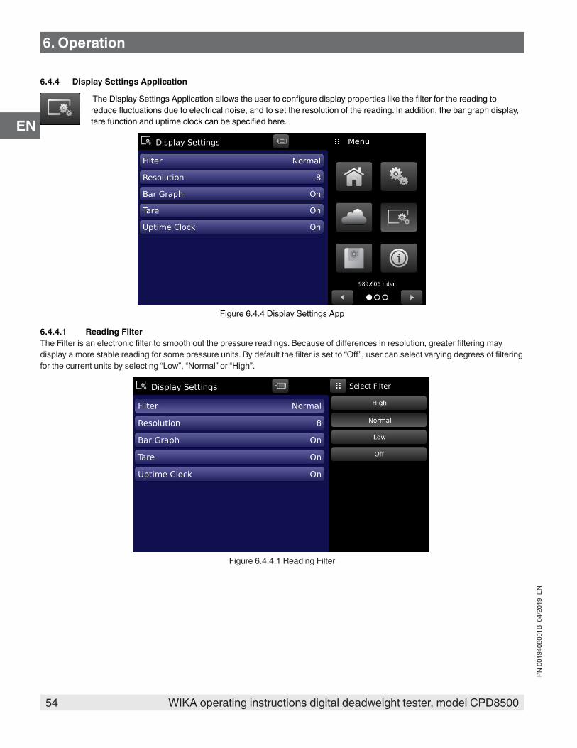
54 WIKA operating instructions digital deadweight tester, model CPD8500
PN 0
0194
0800
1B 0
4/20
19 E
N
EN
6. Operation
6.4.4 Display Settings Application
The Display Settings Application allows the user to configure display properties like the filter for the reading to reduce fluctuations due to electrical noise, and to set the resolution of the reading. In addition, the bar graph display, tare function and uptime clock can be specified here.
Figure 6.4.4 Display Settings App
6.4.4.1 Reading FilterThe Filter is an electronic filter to smooth out the pressure readings. Because of differences in resolution, greater filtering may display a more stable reading for some pressure units. By default the filter is set to “Off”, user can select varying degrees of filtering for the current units by selecting “Low”, “Normal” or “High”.
Figure 6.4.4.1 Reading Filter

55WIKA operating instructions digital deadweight tester, model CPD8500
PN 0
0194
0800
1B 0
4/20
19 E
N
EN
6. Operation
6.4.4.2 Reading ResolutionThe Resolution of the displayed pressure value can be set in the Display Settings Application using the Resolution parameter. The resolution can be set to 5, 6, 7 or 8 digits.
Figure 6.4.4.2 Reading Resolution
6.4.4.3 Bar GraphThe Bar Graph visible on under the displayed pressure value can be turned on/off in the Display Settings Application. The bar graph indicates the relative position of the current value with the maximum range of active measuring head.
6.4.4.4 TareTurning the Tare button “On” will enable the Tare Cal Button [ ] in the Home App. See 6.4.1.8 Tare Button for operation of the Tare button in the Home App (main screen).
Figure 6.4.4 Tare Button
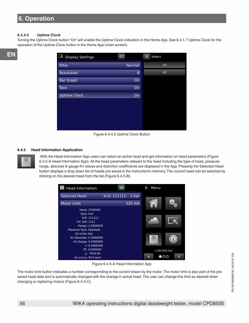
56 WIKA operating instructions digital deadweight tester, model CPD8500
PN 0
0194
0800
1B 0
4/20
19 E
N
EN
6. Operation
6.4.4.5 Uptime ClockTurning the Uptime Clock button “On” will enable the Uptime Clock indication in the Home App. See 6.4.1.7 Uptime Clock for the operation of the Uptime Clock button in the Home App (main screen).
Figure 6.4.4.5 Uptime Clock Button
6.4.5 Head Information Application With the Head Information App users can select an active head and get information on head parameters (Figure 6.4.5-A Head Information App). All the head parameters relevant to the head including the type of head, pressure range, absolute & gauge Kn values and distortion coefficients are displayed in the App. Pressing the Selected Head button displays a drop down list of heads pre saved in the instrument’s memory. The current head can be selected by clicking on the desired head from the list (Figure 6.4.5-B).
Figure 6.4.5-A Head Information App
The motor limit button indicates a number corresponding to the current drawn by the motor. The motor limit is also part of the pre saved head data and is automatically changed with the change in active head. The user can change this limit as desired when changing or replacing motors (Figure 6.4.5-C).
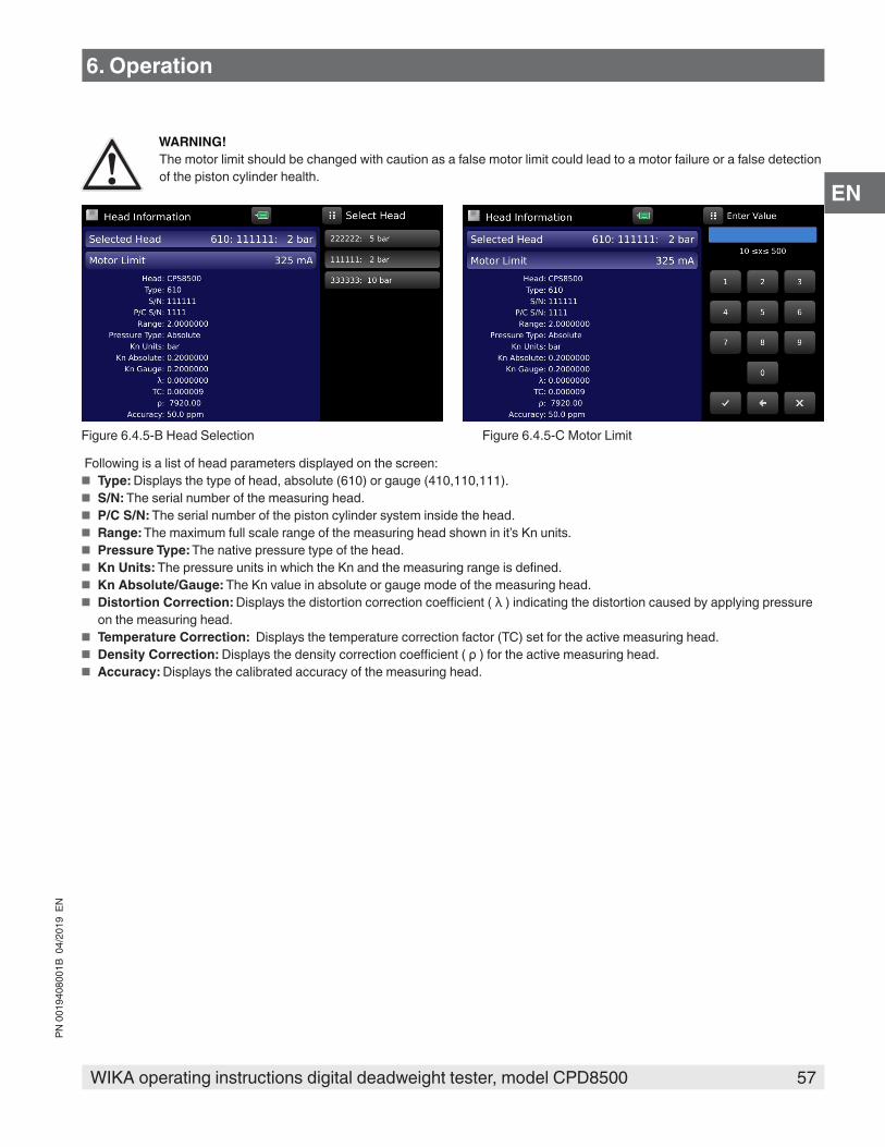
57WIKA operating instructions digital deadweight tester, model CPD8500
PN 0
0194
0800
1B 0
4/20
19 E
N
EN
6. Operation
WARNING!The motor limit should be changed with caution as a false motor limit could lead to a motor failure or a false detection of the piston cylinder health.
Figure 6.4.5-B Head Selection Figure 6.4.5-C Motor Limit
Following is a list of head parameters displayed on the screen: ■ Type: Displays the type of head, absolute (610) or gauge (410,110,111). ■ S/N: The serial number of the measuring head. ■ P/C S/N: The serial number of the piston cylinder system inside the head. ■ Range: The maximum full scale range of the measuring head shown in it’s Kn units. ■ Pressure Type: The native pressure type of the head. ■ Kn Units: The pressure units in which the Kn and the measuring range is defined. ■ Kn Absolute/Gauge: The Kn value in absolute or gauge mode of the measuring head. ■ Distortion Correction: Displays the distortion correction coefficient ( λ ) indicating the distortion caused by applying pressure
on the measuring head. ■ Temperature Correction: Displays the temperature correction factor (TC) set for the active measuring head. ■ Density Correction: Displays the density correction coefficient ( ρ ) for the active measuring head. ■ Accuracy: Displays the calibrated accuracy of the measuring head.

58 WIKA operating instructions digital deadweight tester, model CPD8500
PN 0
0194
0800
1B 0
4/20
19 E
N
EN
6. Operation
6.4.6 Remote Settings Application The Remote Settings Application is accessed by pressing the page forward [ ] button at the bottom of the screen. With the Remote Settings application users can select the remote command set for all interfaces. The GPIB address, Ethernet network parameters and Serial parameters can also be set here.
Figure 6.4.6 Remote App
6.4.6.1 Remote Command SetThe remote command set parameter provides a choice of the Mensor command set or the CPD8000 command set (Figure 6.4.6.1-A). All sets of commands are listed in Section 8, Remote Operation. The termination character sets the output termination character for all remote communication command sets (Figure 6.4.6.1-B).
Figure 6.4.6.1-A Remote Command Set Figure 6.4.6.1-B Termination Character

59WIKA operating instructions digital deadweight tester, model CPD8500
PN 0
0194
0800
1B 0
4/20
19 E
N
EN
6.4.6.2 Remote Communication SettingsThe remainder of the Parameters in the Remote Application present the choice of a numeric entry or a radio button selection. The parameters that require a numeric entry will present a numeric keypad with min and max limits for the variable. The IP address, Netmask and Gateway are displayed on page two of the Remote Settings App.
Setting the Ethernet DHCP to yes will have a short delay while the DHCP server is contacted. If a DHCP server is not found, an error will be indicated. If DHCP is enabled, the IP address, Netmask and Gateway are locked, these are controlled by the DHCP server.
Numeric entry
Radio button selection
6. Operation

60 WIKA operating instructions digital deadweight tester, model CPD8500
PN 0
0194
0800
1B 0
4/20
19 E
N
EN
6.4.7 Information Application
The Information Application displays information about the instrument, including: ■ Address, and email. ■ Base type, serial number , manufacturing date and operating software version. ■ Head model number, range, Kn value, distortion coefficient and temperature coefficient. ■ Load cell serial number, environmental monitoring module serial number, software version. ■ Optional sensor information, model number, serial number and software version.
Figure 6.4.7 Information App
6. Operation

61WIKA operating instructions digital deadweight tester, model CPD8500
PN 0
0194
0800
1B 0
4/20
19 E
N
EN
6.4.8 Troubleshooting Application
The Troubleshoot Application can be found by navigating to the second page in Apps section by clicking on the Next Page [ ] button. The Troubleshoot App will display information about error conditions and remote communications. Within the troubleshoot screen (Figure 6.4.8-B Troubleshoot Screen), scroll the side bar to display any errors that have occurred in the instrument due to a communication or network error. Navigating between local and remote errors can be done by pressing Page Forward [ ] button at the bottom of the screen. If there are any errors in the error queue an error symbol [ ] will appear in all screens (Figure 6.4.8-A Error Indication) of the instrument. Pressing this error button from any screen will open the Troubleshoot application where the error can be viewed.
Figure 6.4.8-A Error Indication
Figure 6.4.8-B Troubleshoot Screen
6. Operation

62 WIKA operating instructions digital deadweight tester, model CPD8500
PN 0
0194
0800
1B 0
4/20
19 E
N
EN
6.4.9 Service Application
The service application is a password protected area where calibration of all connected transducers and devices can be accomplished. In addition, this is where the password for entering this area can be changed.
Figure 6.4.9-A Service App (Locked)
Press the Enter button to show the numeric keypad to enter a password. This will unlock applications that assist with the calibration of all devices. Default password is 123456. Enter 123456 and press the check mark [ ] to unlock the Service Application.
Note: The default password is 123456. After entering this for the first time, the password can be changed.
After the Password has been entered, the unlocked Service Application will appear (Figure 6.4.10 Unlocked Service App). To re-lock this screen, press the lock button.
Figure 6.4.10 Unlocked Service App
6. Operation

63WIKA operating instructions digital deadweight tester, model CPD8500
PN 0
0194
0800
1B 0
4/20
19 E
N
EN
From the Unlocked Service Application, the Password can be changed by pressing the Change Calibration Password button next to the Change Password label. This will open a keypad where a new password can be entered and accepted by pressing the Check Mark [ ].
Note: Please make note of a password change and save the new password in a secure location.
The Unlocked Service Application is the access point to all calibration screens described in Section 8. Maintenance and Recalibration of this manual.
Note: Recommended calibration setup and explanation of calibration screen applications is covered in Section 8. Maintenance and Recalibration of this manual.
6. Operation

64 WIKA operating instructions digital deadweight tester, model CPD8500
PN 0
0194
0800
1B 0
4/20
19 E
N
EN
7. Remote Operation
7. Remote Operation
7.1 Remote Operating ParametersUse the screens in Section 6.4.6 Remote Settings Application to set the remote operating parameters for the instrument command set, Ethernet, Serial (RS-232) and IEEE-488 (GPIB) communications.
7.2 Command SetCommand Set button – Users’ can select which model remote protocol they would like to emulate for simulation and testing purposes. Selections may include the following or may be added per customers’ specifications:
■ Mensor ■ CPD8000 (The CPD8000 mode emulates the CPD8000 command set for backwards compatibility.)
7.3 IEEE-488IEEE-488 address button – Allows the user to set the GPIB address by inputting a numeric value utilizing the touch screen.
7.3.1 IEEE-488.2 Commands
Command Response/ Function*IDN? Returns identification string
7.4 EthernetThe Ethernet function allows the user to set the following by inputting a numeric value in each separate field:
■ IP ■ Netmask ■ Gateway ■ Port ■ DHCP settings
Set the Ethernet communication parameters as described in 6.4.6 Remote Settings Application.
CAUTION! Please contact your network administrator forproper settings.
CAUTION! Please consult your computer resources department prior to connecting this instrument to your network to verify there are no conflicts with existing IP addresses.
The Ethernet communication port allows the CPD8500 to communicate with computers using 10/100Based-T specifications.Before using Ethernet communication, four parameters must be present: IP, Netmask, Gateway, and Port.

65WIKA operating instructions digital deadweight tester, model CPD8500
PN 0
0194
0800
1B 0
4/20
19 E
N
EN
7.5 SerialSet the Serial communication parameters as shown in Section 6.4.6 Remote Settings Application. The serial communication port allows the CPD8500 to communicate in RS-232 format with computers, terminals, PDAs, or similar hosts.These parameters should be set to match your host computer. Default settings are: 9600 baud, 8 data bits, 1 stop bit, no parity, and no echo.If echo is ON, the CPD8500 will immediately echo back characters sent over the serial port. The Serial function allows the user to set the RS-232 serial port settings by selecting from the choices provided:
■ Baud ⇒ 9600 ⇒ 19200 ⇒ 38400 ⇒ 57600 ⇒ 115200
■ Data Bits ⇒ 7 ⇒ 8
■ Stop Bits ⇒ 1 ⇒ 2
■ Parity ⇒ Even ⇒ Odd ⇒ None
■ Echo settings ⇒ On ⇒ Off
7.5.1 Serial Cable RequirementsRS-232 communications are transmitted over a three conductor, shielded cable terminated in a standard DB9 connector on the instrument end, and a different gender connector on the host end. The proper pin-outs are shown in the following illustration.
7. Remote Operation

66 WIKA operating instructions digital deadweight tester, model CPD8500
PN 0
0194
0800
1B 0
4/20
19 E
N
EN
7.6 Mensor Command SetThis Mensor command set is the default on the CPD8500. For queries (ending with a ?), the Data column represents the response of the CPD8500. All response strings begin with a space character or an “E” representing that there is an error in the error queue. All response strings are terminated with a termination character set in the Remote Settings Screen (Section 6.4.6 Remote Settings Application). The error queue holds the last 10 errors identified.For all commands (no ?), the data column represents the required parameters to be sent to the CPD8500 following the string in the command column. For any command that requires multiple parameters to be sent, the parameters must be separated by commas.
7.6.1 Command and Query FormatCommands must be sent in ASCII format and terminated with either a carriage return (<cr>), linefeed (<lf>), or both. Commands are not case sensitive. Each query returns a response. If an error is detected the response will include an error flag.Command or Query field: Unless otherwise specified, commands are typically converted to queries by appending a question mark to the command. Table 7.10 lists all of the CPD8500 command or query keywords.Data field: The data field is either in ASCII {string} or numeric {value} form. In the case of multiple data fields, commas are required to separate the fields. Queries do not have a data field. String (text) or value (numeric) data are acceptable in any of the following formats:Examples of {string} data: ON, OFF, mBar, inHg Examples of {value} data: 1, 1.0, -5.678, 25.68324e-5
7.6.2 Command Set DefinitionsIn this manual a data entry made up of alpha characters is defined as a string, as opposed to data containing only numbers, such as “Enter 1 for ON or 0 for OFF” where 1 and 0 are defined as values.Command: Any command or query listed in Table 7.6.4. For commands that take boolean data the following strings are acceptable:0 1 False True No Yes Off OnSeparator: Space (SP).Data: ASCII representations of numbers, {value}, or alpha characters, {string}, data as defined above. When sending code a literal variable replaces the brackets and the enclosed character(s) shown in the following examples.Termination: Linefeed (LF) or carriage return (CR) is used to signal the end of a command statement. For IEEE-488.2 operation “EOI” is an acceptable alternative.Always send commands in one of the following formats: 1. [Command] [Termination]; 2. [Command] [Separator] [Data] [Termination]; 3. Queries are special instructions in the form: [Command?] [Termination] where the question mark, “?”, immediately precedes the
terminator.When a valid query is received, the CPD8500 will return {data} terminated by termination character set in the Remote Settings Screen (Section 6.4.6 Remote Settings Application) . Floating point data is returned in the current engineering units in exponential format.
7.6.3 Output FormatsPressure readings are returned in exponential notation in a format according to the OUTFORM command as follows.Output formats 1. pressure value 2. pressure, head temperature 3. pressure value, minimum peak pressure, maximum peak pressure4. pressure value, baro reading where baro reading is the external barometer reading if present or internal barometer reading if external is not present or "NO BAROMETER" if neither one is present5. pressure value, head temperature reading, ambient pressure reading, ambient temperature reading, relative humidity reading6. pressure value, barometer reading if present, vacuum sensor reading if present, head temperature reading, ambient pressure reading, ambient temperature reading, relative humidity reading
7. Remote Operation

67WIKA operating instructions digital deadweight tester, model CPD8500
PN 0
0194
0800
1B 0
4/20
19 E
N
EN
7.6.4 Mensor Commands and QueriesTable 7.6.4 lists all of the current mensor commands and queries.
Optional emulation modes are available in which a CPD8500 can emulate remote functions of different brands of pressure gauges. Please contact Mensor for more details.
Command Data Response/Function? See Section 7.6.3 Output Formats Returns data per the current output format
Acquire? 15 char string. Ex: Acquire? Test_stand_1 Returns: <sp>(YES or NO), CCC…CCC<cr><lf>
This command is used when multiple computers would like to control the instrument. Yes if acquisition is successful. No if instrument is being controlled with another computer. CCC...= name of controlling computer (see Release? and Unlock)
Address 1-31 Sets the GPIB AddressAddress? <sp>nn<cr><lf> Returns the GPIB AddressAmbpress? <sp>+n.nnnnnE+nn<cr><lf> Returns the ambient pressure from the EMMAmbtemp? <sp>+n.nnnnnE+nn<cr><lf> Returns the ambient temperature from the EMMAmbrh? <sp>+n.nnnnnE+nn<cr><lf> Returns the ambient humidity from the EMMAsset_tag 16 char string. General purpose string for customer useAsset_tag? <sp>ssssssssssssssss<cr><lf> Return customer asset tag stringAuxdisp <n> NONE,UNCERTAINTY,PEAK,UNITS,HEADTEMP,
AMBTEMP,AMBRH,AMBPRESS, MASS, EMM, (on absolute base only: RESPRESS)
Sets the auxiliary display setting for index <n> (1 to 3). If <n> is left out, defaults to index 1.
Auxdisp? <n> <sp> NONE,UNCERTAINTY,PEAK,UNITS,HEAD-TEMP, AMBTEMP,AMBRH,AMBPRESS,MASS, EMM, (on absolute base only:RESPRESS) <cr><lf>
Returns the auxiliary display setting for index <n>. If <n> is left out, defaults to index 1.
Baro? <sp>+n.nnnnnE+nn<cr><lf> Returns reading from barometric transducer or “NO BAROMETER” if one isn’t installed
Calculate_as_found_linearity Calculate linearity slopes and intercepts from indicat-ed/actual input values
Caldisable YES, NO Sets whether or not calibration of the active sensor is disabled.
Caldisable? <sp>(YES or NO)<cr><lf> Returns whether or not calibration of the active sensor is disabled.
Cerr None Clears the error queueCmdset Mensor, CPD8000 Activates remote command set for instrument emula-
tion modes.Cmdset? <sp><CCCCCC><cr><lf> Returns active command set identifierDECPT? <sp>n<cr><lf> Returns the number of decimal points (see Resolution)DHCP ON or OFF Reserved for DHCP setupDHCP? <sp>(YES or NO)<cr><lf> Reserved for DHCP setupDOC mm/dd/yyyy Sets the date of cal for the active sensor.DOC? <sp>mm/dd/yyyy<cr><lf> Returns the date of cal for the active sensor.DOM? <sp>mm/dd/yyyy<cr><lf> Returns the date of manufactureError? <sp> text description <cr><lf> Returns the next error in the error queueFilter OFF, LOW, NORMAL, HIGH Sets the reading filter 0, 80%, 92%, 95%Filter? <sp> (filter)<cr><lf> Returns the reading filter.Gadensity “NITROGEN” or “DRYAIR” Sets the head pressure gas density in lb/cuftGasdensity? <sp>+n.nnnnnnnE+nn<cr><lf> Gets the head pressure gas density in lb/cuft
7. Remote Operation
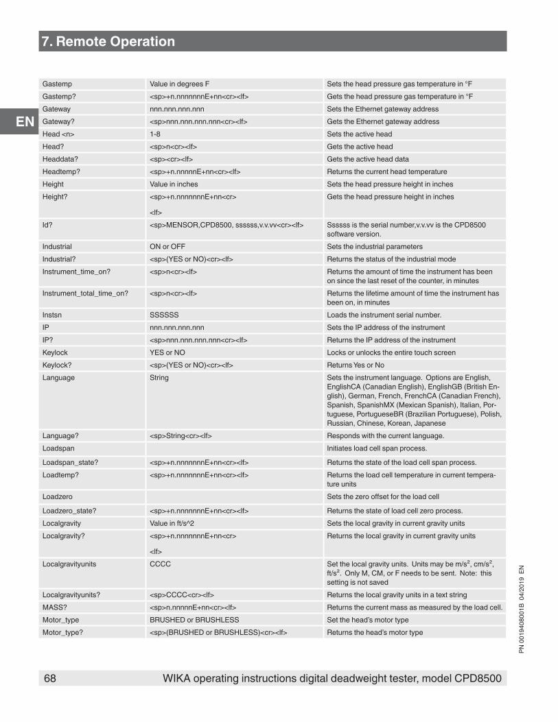
68 WIKA operating instructions digital deadweight tester, model CPD8500
PN 0
0194
0800
1B 0
4/20
19 E
N
EN
Gastemp Value in degrees F Sets the head pressure gas temperature in °FGastemp? <sp>+n.nnnnnnnE+nn<cr><lf> Gets the head pressure gas temperature in °FGateway nnn.nnn.nnn.nnn Sets the Ethernet gateway addressGateway? <sp>nnn.nnn.nnn.nnn<cr><lf> Gets the Ethernet gateway addressHead <n> 1-8 Sets the active headHead? <sp>n<cr><lf> Gets the active headHeaddata? <sp><cr><lf> Gets the active head dataHeadtemp? <sp>+n.nnnnnE+nn<cr><lf> Returns the current head temperatureHeight Value in inches Sets the head pressure height in inchesHeight? <sp>+n.nnnnnnnE+nn<cr>
<lf>
Gets the head pressure height in inches
Id? <sp>MENSOR,CPD8500, ssssss,v.v.vv<cr><lf> Ssssss is the serial number,v.v.vv is the CPD8500 software version.
Industrial ON or OFF Sets the industrial parametersIndustrial? <sp>(YES or NO)<cr><lf> Returns the status of the industrial modeInstrument_time_on? <sp>n<cr><lf> Returns the amount of time the instrument has been
on since the last reset of the counter, in minutesInstrument_total_time_on? <sp>n<cr><lf> Returns the lifetime amount of time the instrument has
been on, in minutesInstsn SSSSSS Loads the instrument serial number.IP nnn.nnn.nnn.nnn Sets the IP address of the instrumentIP? <sp>nnn.nnn.nnn.nnn<cr><lf> Returns the IP address of the instrumentKeylock YES or NO Locks or unlocks the entire touch screenKeylock? <sp>(YES or NO)<cr><lf> Returns Yes or NoLanguage String Sets the instrument language. Options are English,
EnglishCA (Canadian English), EnglishGB (British En-glish), German, French, FrenchCA (Canadian French), Spanish, SpanishMX (Mexican Spanish), Italian, Por-tuguese, PortugueseBR (Brazilian Portuguese), Polish, Russian, Chinese, Korean, Japanese
Language? <sp>String<cr><lf> Responds with the current language.Loadspan Initiates load cell span process.
Loadspan_state? <sp>+n.nnnnnnnE+nn<cr><lf> Returns the state of the load cell span process.Loadtemp? <sp>+n.nnnnnnnE+nn<cr><lf> Returns the load cell temperature in current tempera-
ture unitsLoadzero Sets the zero offset for the load cell
Loadzero_state? <sp>+n.nnnnnnnE+nn<cr><lf> Returns the state of load cell zero process.Localgravity Value in ft/s^2 Sets the local gravity in current gravity unitsLocalgravity? <sp>+n.nnnnnnnE+nn<cr>
<lf>
Returns the local gravity in current gravity units
Localgravityunits CCCC Set the local gravity units. Units may be m/s², cm/s², ft/s². Only M, CM, or F needs to be sent. Note: this setting is not saved
Localgravityunits? <sp>CCCC<cr><lf> Returns the local gravity units in a text stringMASS? <sp>n.nnnnnE+nn<cr><lf> Returns the current mass as measured by the load cell.Motor_type BRUSHED or BRUSHLESS Set the head’s motor typeMotor_type? <sp>(BRUSHED or BRUSHLESS)<cr><lf> Returns the head’s motor type
7. Remote Operation

69WIKA operating instructions digital deadweight tester, model CPD8500
PN 0
0194
0800
1B 0
4/20
19 E
N
EN
Motor_limit n Set the head’s motor current limit in mA between 10-500
Motor_limit? <sp>n<cr><lf> Returns the head’s motor current limit in mAMotor_speed n Set the head’s motor speed percent from 0 to 100Motor_speed? <sp>n<cr><lf> Returns the head’s motor speed in percent 0 to 100Netmask nnn.nnn.nnn.nnn Sets the Ethernet network maskNetmask? <sp>nnn.nnn.nnn.nnn<cr><lf> Gets the Ethernet network maskOutform 1 to 6 – see Section 7.6.3 Output Formats Sets the output formatOutform? <sp>X<cr><lf> Returns the output format – see table in Section 7.10Peakmax? <sp>n.nnnnnE+nn<cr><lf> Returns the maximum pressure since peakreset was
sentPeakmin? <sp>n.nnnnnE+nn<cr><lf> Returns the minimum pressure since peakreset was
sentPeakreset None Resets the peak values.Port nnnnnn Sets the Ethernet port of the instrumentPort? <sp>nnnnn<cr><lf> Returns the Ethernet port of the instrumentPrecision ON or OFF Sets the precision parametersPrecision? <sp>(YES or NO)<cr><lf> Returns the status of the precision modePtype Absolute, Gauge or Bidirectional Sets the instrument pressure type – bidirectional only
works on absolute bases if the optional barometric transducer is installed.
Ptype? <sp>CCCCC<cr><lf> Returns “Absolute” or “Gauge” for the pressure type in native mode and “Bidirectional” for the emulated pressure types.
RangeMax? <sp>n.nnnnnE+nn<cr><lf> Returns the maximum range of the active measuring head in the current units.
RangeMin? <sp>n.nnnnnE+nn<cr><lf> Returns the minimum range of the active measuring head in the current units.
Release? 15 char string.
Ex:
Release? Test_stand_1
Returns:
<sp>(YES or NO), CCC…CCC<cr><lf>
This command is used to release control of the instru-ment in a multiple computer environment.
Yes if release is successful
No if instrument is being controlled with another computer
CCC… = name of controlling computer or AVAILABLE
See: Acquire? and UnlockResolution <n> Sets the number of significant digits. (see decpt)Resolution? <sp>n<cr><lf> Returns the number of significant digits. (see decpt)Reset_instrument_time_on Resets the instrument’s time on counter. See usage
application for more detailsSbaud 300, 600, 1200, 2400, 4800, 9600, 19200, 38400,
57600, 115200Sets the serial and USB baud rate
Sbaud? <sp>XXXX<cr><lf> Returns the serial and USB baud dataSdata 7 or 8 Sets the serial and USB data bitsSdata? <sp>n<cr><lf> Returns the serial and USB data bits numberSensor HEAD, HEADTEMP, AMBPRESS, AMBTEMP, HU-
MIDITY, BARO, VACSets the sensor for cal functions
Sensor? <sp>ssss<cr><lf> Gets the sensor for cal functionsSpan Initiates active device span process. Not valid for the
head device
7. Remote Operation

70 WIKA operating instructions digital deadweight tester, model CPD8500
PN 0
0194
0800
1B 0
4/20
19 E
N
EN
Span? <sp>+n.nnnnnnnE+nn<cr><lf> Returns the active device’s span multiplier. Not valid for the head device
Sparity EVEN, ODD, NONE Sets the serial and USB paritySparity? <sp>CCCC<cr><lf> Returns the serial and USB paritySrqmask “None”
“Stable”
“Error”
“Error,Stable”
Sets the CPD8500 to issue a service request (SRQ) over the IEEE when the pressure
Control is stable, or an error occurs. These are 0x02 and 0x01 in hex, respectively.
Srqmask? <sp>{string}<cr><lf> Returns “NONE”, “STABLE”, ”ERROR” or “ER-ROR,STABLE” depending on the SRQ mask.
Sstop 1 or 2 Sets the serial and USB stop bitsSstop? <sp>X<cr><lf> Returns the serial and USB stop bitsStable? Returns YES if instrument is stable or NoStabledelay 0 to 120 Sets the stable time to the number of seconds speci-
fiedStabledelay? <sp>XXXXXXX<cr><lf> Returns the stable time.Stablewin %fs value Sets the stable window for the active deviceStablewin? <sp>+n.nnnnnnnE+nn<cr>
<lf>
Returns the stable window for the active device
Tare ON / OFF Tares the reading to zeroTare? <sp> n.nnnnnE+nn <cr><lf> Returns value of TareTransfer_factory_to_linearity Copy factory linearity coefficients to customerUncertainty? <sp>+n.nnnnnnnE+nn<cr><lf> Returns the uncertainty in current engineering units.
Dependent on the current reading, active head, and active pressure type.
Units Units code or text in table below Sets the instrument engineering unitsUnits? <sp>CCCC<cr><lf> Returns the instrument units in a text stringUnlock None Releases Acquire locks
See Acquire? And Release?Vacuum? <sp>+n.nnnnnE+nn<cr><lf> Returns the current residual pressure from the vacuum
sensorZero Sets the zero offset for the active device. Not valid for
the head deviceZero? <sp>+n.nnnnnnnE+nn<cr><lf> Returns the active device’s zero offset. Not valid for
the head device
7. Remote Operation

71WIKA operating instructions digital deadweight tester, model CPD8500
PN 0
0194
0800
1B 0
4/20
19 E
N
EN
7.6.5 Units Command Syntax for Measurement Units
n Description Output Format Type
1 pounds per square inch PSI Imperial2 inches of mercury @ 0°C INHG Imperial3 inches of mercury @ 60°F INHG Imperial4 inches of water @ 4°C INH2O Imperial5 inches of water @ 20°C INH2O Imperial6 inches of water @ 60°F INH2O Imperial7 feet of water @ 4°C FTH2O Imperial8 feet of water @ 20°C FTH2O Imperial9 feet of water @ 60°F FTH2O Imperial10 millitorr MTORR Metric11 inches of sea water @ 0°C INSW Imperial12 feet of sea water @ 0°C FTSW Imperial13 atmospheres ATM Imperial14 bars BAR Metric15 millibars MBAR Metric16 millimeters of water @ 4°C MMH2O Metric17 centimeters of water @ 4°C CMH2O Metric18 meters of water @ 4°C MH2O Metric19 millimeters of mercury @ 0°C MMHG Metric20 centimeters of mercury @ 0°C CMHG Metric21 torr TORR Metric22 kilopascals KPA Metric23 pascals PA Metric24 dynes per square centimeter DY/CM2 Metric25 grams per square centimeter G/CM2 Metric26 kilograms per square centimeter KG/CM2 Metric27 meters of sea water @ 0°C MSW Metric28 ounce per square inch OSI Imperial29 pounds per square foot PSF Imperial30 tons per square foot TSF Imperial32 micron of mercury @ 0°C mHG Metric33 tons per square inch TSI Imperial34 meters of mercury @ 0°C MHG Metric35 hectapascals HPA Metric36 megapascals MPA Metric37 millimeters of water @ 20°C MMH2O Metric38 centimeters of water @ 20C CMH2O Metric39 meters of water @ 20°C MH2O Metric
7. Remote Operation

72 WIKA operating instructions digital deadweight tester, model CPD8500
PN 0
0194
0800
1B 0
4/20
19 E
N
EN
7.7 CPD8500 Command SetThe CPD8500 emulates the remote communication used in its predecessor CPD8000 and DPG5, DPG8 and DPG10.
7.7.1 Command and Query FormatCommands must be sent in ASCII format and terminated with either a carriage return (<cr>), linefeed (<lf>), or both. Commands are not case sensitive. Each query returns a response. If an error is detected the response will include an error flag.Command or Query field: Unless otherwise specified, commands are typically converted to queries by appending a question mark to the command. Table 7.7.3 lists all of the CPD8500 command or query keywords.
7.7.2 Command Set DefinitionsIn this manual a data entry made up of alpha characters is defined as a string, as opposed to data containing only numbers, such as “Enter 1 for ON or 0 for OFF” where 1 and 0 are defined as values.Command: Any command or query listed in Table 7.7.3. The commands, which are indicated with ‘=’ (query & return) can be used either to read or to determine a value.Separator: Space (SP).Data: ASCII representations of numbers, {value}, or alpha characters, {string}, data as defined above. When sending code a literal variable replaces the brackets and the enclosed character(s) shown in the following examples.Termination: Linefeed (LF) or carriage return (CR) is used to signal the end of a command statement. Therefore, the message is a character chain, with CR and LF marking the end of the chain.When a valid query is received, the CPD8500 will return {data} terminated by CR and LF.When a command is not supported, the received message is answered back and followed by ?Status of the instrument: When the CPD8500 is performing the calibration, the zeroing or the configuration of the DPM, no other command are valid. The CPD8500 answer STS=1 until the action in progress is finished.The command STS can be used to check if one the action mentioned is completed (STS=0) or not (STS=1). The command ERR should be used to check if the action succeed (ERR=0) or not.
7.7.3 CPD8500 Commands and QueriesTable 7.7.3 lists all of the current Mensor commands and queries. Commands which have (**) at the end are currently not supported by the CPD8500.
Command Query & Return
Description Unit Typical Response
ABS Test if absolute or gauge mode ABS = ON or ABS = OFF ABS= ON if DPM connected or vacuum < 20Pa (CPD8000 A)
ATM Ambient atmospheric pressure EMM sensor measurement
hPa 1013 hPa
BLC = Measuring head number 2BRM** = Initialisation of the external barometer BRM = 0 or BRM = 1
CAL Calibration CAL = S or CAL = NCOM = RS232 communication rate Baud 9600DAT** = Date (dd-mm-yyyy) 12-05-1997DIG = Selection of the number of digits 2ERR (2) Error code ERR = 0ESC** Cancellation of the modifications ESC = Y or ESC = NFIL = Selection of the filter 0HUM Relative ambient humidity EMM sensor
measurement% 68.3 %
IDN Identification of the standard, version of the internal software and serial number
DPG - Ver 3.15 - 9707
7. Remote Operation

73WIKA operating instructions digital deadweight tester, model CPD8500
PN 0
0194
0800
1B 0
4/20
19 E
N
EN
LCL Return to local mode LCL = OK
MPB Barometric pressure external sensor mea-surement
Pa 101325 Pa
MPI Immediate pressure measurement S (stable) 8952.31 mbar I (unstable) 8952.31 mbar
MPR Repeated pressure measurement MPR : mbar 8952.31 8953.24
MPV Reading of the residential vacuum Pa 2.03 PaMVL Instantaneous air mass density kg/m3 1.22 kg/cm3NBA** = External barometer serial number 9918NBC = Measuring head serial number 99101NPC = P/C assembly serial number 7658OPI = Offset of the Pirani 0.02PAC** Coefficient Pa of the DPMPAS = Password confirmationPMC** Coefficient PM of the DPMPUN = Pressure unit 4
RNG CPD 8000 measuring range according to the selected measuring block.
0.07 bar
RPC** = Head temperature probe resistance Ohm 100.02RST = Reset to default valuesSAV** Modifications saving SAV = Y or SAV = NSGL = Local gravity value m/s2 9.80665SI (1) Measuring cell measured value g S * 809.27 gSMV = External calibration masses density kg/m3 7920SPC = Piston-cylinder Kn 20.000123
STS (3) CPD8000 status STS = 1 (busy) if CAL, TAR, BRM
T (1) Cell tarring TA (ok) or TL (not ok)
TAM Ambient temperature EMM sensor measure-ment
°C 23.2 °C
TAR = Standard's tarring TAR = S
TIM** = Time (hh-mm-ss) 15-56-22TPC Piston temperature °C 24.6 °CTST Calibration test TST = S TST = 0.00UPC = Kn unit (bar or psi) 0 (bar/kg), 1 (psi/kg)
UUC = User unit coefficient 0.5UUN** = User unit label USERWNG Calibration indication
ZST = Pressure stability selection (P/s unit) 0,01 (mbar/s)
7. Remote Operation

74 WIKA operating instructions digital deadweight tester, model CPD8500
PN 0
0194
0800
1B 0
4/20
19 E
N
EN
7.8 Error Codes
Error Codes Error Text
General ErrorsERR_NONE No ErrorERR_OPEN Device Open ErrorERR_NOT_CONNECTED Device Not Connected ErrorERR_TIMEOUT Device TimeoutERR_COMMUNICATION Communication ErrorERR_BUFFER_OVERFLOW Buffer Overflow ErrorERR_FILE_CHECK File Check ErrorERR_NOT_ASSIGNED Unassigned Function ErrorERR_STATUS New StatusApplication or Device Specific ErrorsERR_HDF_FILE_NOT_FOUND Saved HDF not found. Set to next availableERR_HDF_NO_VALID_FILE_FOUND No HDF found. Create new or copy from USBERR_CALIBRATION Calibration ErrorERR_CALIBRATION_SPAN_READING_TOO_LOW Cal Error: Unable to set span below 50%ERR_CALIBRATION_LINEARITY_INPUT_DATA Cal Error: Data entry incompleteERR_CALIBRATION_LINEARITY_UNABLE_CORRECT Cal Error: Unable to adjust. Check input dataERR_CALIBRATION_LINEARITY_SEGMENT_CHECK Cal Error: Segment discontinuityERR_CALIBRATION_LINEARITY_LIMIT Linearity point limit errorERR_CALIBRATION_LINEARITY_LIMIT_DOWNSCALE Linearity downscale limit errorERR_CALIBRATION_LINEARITY_LIMIT_UPSCALE Linearity upscale limit errorERR_MOTOR_FAULT Motor fault detectedERR_MOTOR_OVER_THRESHOLD Motor Limit: Please clean piston/cylinderERR_MOTOR_NOT_CONNECTED Motor Fault : Check motor cableERR_LOADCELL_INIT Load cell: Initialization errorERR_LOADCELL_INIT_MODE Load cell: Unable to initialize modeERR_LOADCELL_INIT_MODE_BAD Load cell: Initialization bad modeERR_LOADCELL_INIT_AUTOZERO Load cell: Unable to initialize autozeroERR_LOADCELL_INIT_AUTOZERO_BAD Load cell: Initialization bad autozeroERR_LOADCELL_INIT_UNIT Load cell: Unable to initialize unitsERR_LOADCELL_INIT_BAD_UNIT Load cell: Initialization bad unitsERR_LOADCELL_INIT_CAL Load cell: Unable to initialize calibrationERR_LOADCELL_INIT_BAD_CAL Load cell: Initialization bad calibrationERR_LOADCELL_CAL_TEST_TIMEOUT Load cell: Cal Test process timed outERR_LOADCELL_CAL_TEST_ABORT Load cell: Cal Test abortedERR_LOADCELL_CAL_TEST_IMPOSSIBLE Load cell: Cal Test not possibleERR_LOADCELL_CAL_TEST_NOT_PERFORM Load cell: Cal Test not performedERR_LOADCELL_TARE_TIMEOUT Load cell: Tare process timed outERR_LOADCELL_TARE_DISABLE Load cell: Tare disable not performedERR_LOADCELL_TARE_NOT_PERFORM Load cell: Tare not performedERR_LOADCELL_TARE_LOWER_LIMIT Load cell: Tare lower limit exceededERR_LOADCELL_TARE_UPPER_LIMIT Load cell: Tare upper limit exceededERR_LOADCELL_ZERO Load cell: Zero calibration process error
7. Remote Operation
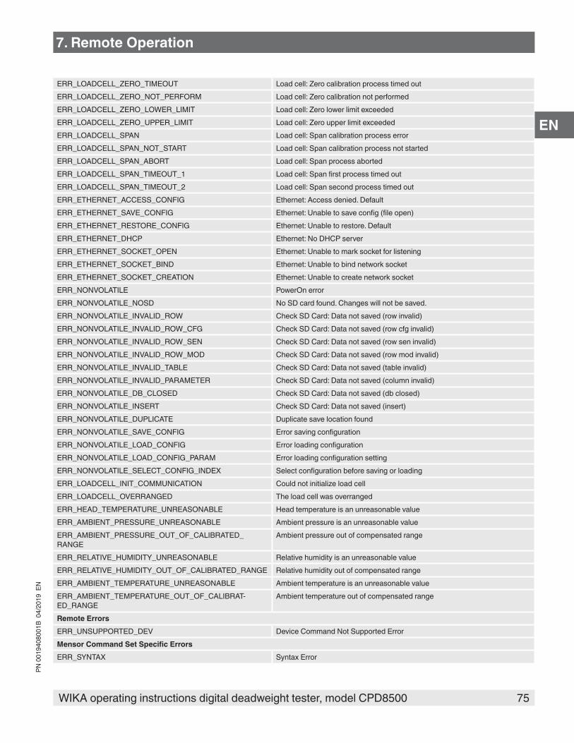
75WIKA operating instructions digital deadweight tester, model CPD8500
PN 0
0194
0800
1B 0
4/20
19 E
N
EN
ERR_LOADCELL_ZERO_TIMEOUT Load cell: Zero calibration process timed outERR_LOADCELL_ZERO_NOT_PERFORM Load cell: Zero calibration not performedERR_LOADCELL_ZERO_LOWER_LIMIT Load cell: Zero lower limit exceededERR_LOADCELL_ZERO_UPPER_LIMIT Load cell: Zero upper limit exceededERR_LOADCELL_SPAN Load cell: Span calibration process errorERR_LOADCELL_SPAN_NOT_START Load cell: Span calibration process not startedERR_LOADCELL_SPAN_ABORT Load cell: Span process abortedERR_LOADCELL_SPAN_TIMEOUT_1 Load cell: Span first process timed outERR_LOADCELL_SPAN_TIMEOUT_2 Load cell: Span second process timed outERR_ETHERNET_ACCESS_CONFIG Ethernet: Access denied. DefaultERR_ETHERNET_SAVE_CONFIG Ethernet: Unable to save config (file open)ERR_ETHERNET_RESTORE_CONFIG Ethernet: Unable to restore. DefaultERR_ETHERNET_DHCP Ethernet: No DHCP serverERR_ETHERNET_SOCKET_OPEN Ethernet: Unable to mark socket for listeningERR_ETHERNET_SOCKET_BIND Ethernet: Unable to bind network socketERR_ETHERNET_SOCKET_CREATION Ethernet: Unable to create network socketERR_NONVOLATILE PowerOn errorERR_NONVOLATILE_NOSD No SD card found. Changes will not be saved.ERR_NONVOLATILE_INVALID_ROW Check SD Card: Data not saved (row invalid)ERR_NONVOLATILE_INVALID_ROW_CFG Check SD Card: Data not saved (row cfg invalid)ERR_NONVOLATILE_INVALID_ROW_SEN Check SD Card: Data not saved (row sen invalid)ERR_NONVOLATILE_INVALID_ROW_MOD Check SD Card: Data not saved (row mod invalid)ERR_NONVOLATILE_INVALID_TABLE Check SD Card: Data not saved (table invalid)ERR_NONVOLATILE_INVALID_PARAMETER Check SD Card: Data not saved (column invalid)ERR_NONVOLATILE_DB_CLOSED Check SD Card: Data not saved (db closed)ERR_NONVOLATILE_INSERT Check SD Card: Data not saved (insert)ERR_NONVOLATILE_DUPLICATE Duplicate save location foundERR_NONVOLATILE_SAVE_CONFIG Error saving configurationERR_NONVOLATILE_LOAD_CONFIG Error loading configurationERR_NONVOLATILE_LOAD_CONFIG_PARAM Error loading configuration settingERR_NONVOLATILE_SELECT_CONFIG_INDEX Select configuration before saving or loadingERR_LOADCELL_INIT_COMMUNICATION Could not initialize load cellERR_LOADCELL_OVERRANGED The load cell was overrangedERR_HEAD_TEMPERATURE_UNREASONABLE Head temperature is an unreasonable valueERR_AMBIENT_PRESSURE_UNREASONABLE Ambient pressure is an unreasonable valueERR_AMBIENT_PRESSURE_OUT_OF_CALIBRATED_RANGE
Ambient pressure out of compensated range
ERR_RELATIVE_HUMIDITY_UNREASONABLE Relative humidity is an unreasonable valueERR_RELATIVE_HUMIDITY_OUT_OF_CALIBRATED_RANGE Relative humidity out of compensated range ERR_AMBIENT_TEMPERATURE_UNREASONABLE Ambient temperature is an unreasonable valueERR_AMBIENT_TEMPERATURE_OUT_OF_CALIBRAT-ED_RANGE
Ambient temperature out of compensated range
Remote ErrorsERR_UNSUPPORTED_DEV Device Command Not Supported ErrorMensor Command Set Specific ErrorsERR_SYNTAX Syntax Error
7. Remote Operation

76 WIKA operating instructions digital deadweight tester, model CPD8500
PN 0
0194
0800
1B 0
4/20
19 E
N
EN
ERR_PARAMETER Parameter ErrorERR_INDEX_OUT_OF_RANGE Index Out of Range ErrorERR_NUMERIC_FORMAT Number Format ErrorERR_FAILED_CMD Failed Command ErrorCPD8000 Command Set Specific ErrorsERR_DH_REMOTE_CMD 0 Communication Error - Bad CommandERR_DH_UNSTABLE 1 Load Cell Unstable - Unable to tare or calERR_DH_NOT_AT_ZERO 2 Load Cell Not at Zero - Unable to calERR_DH_BARO_INIT_FAILED 3 Barometer Initialization FailedERR_DH_CELL_OVERLOAD 4 Load Cell Over loadedERR_DH_CELL_UNDERLOAD 5 Load Cell Under loadedERR_DH_READING_IN_MENU 6 Pressure Reading in Menu ModeERR_DH_TARE_FAIL 7 Calibration Test Failed
7. Remote Operation
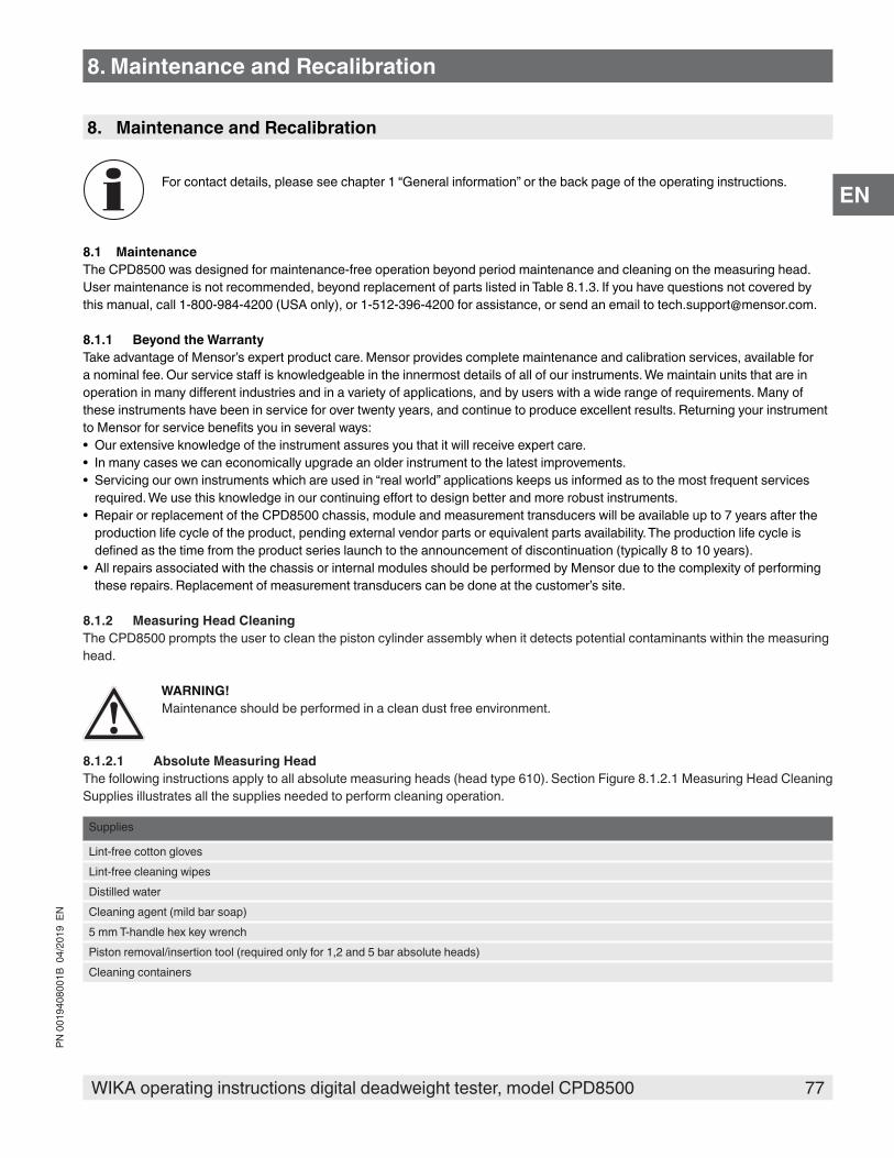
77WIKA operating instructions digital deadweight tester, model CPD8500
PN 0
0194
0800
1B 0
4/20
19 E
N
EN
8. Maintenance and Recalibration
For contact details, please see chapter 1 “General information” or the back page of the operating instructions.
8.1 MaintenanceThe CPD8500 was designed for maintenance-free operation beyond period maintenance and cleaning on the measuring head. User maintenance is not recommended, beyond replacement of parts listed in Table 8.1.3. If you have questions not covered by this manual, call 1-800-984-4200 (USA only), or 1-512-396-4200 for assistance, or send an email to [email protected].
8.1.1 Beyond the WarrantyTake advantage of Mensor’s expert product care. Mensor provides complete maintenance and calibration services, available for a nominal fee. Our service staff is knowledgeable in the innermost details of all of our instruments. We maintain units that are in operation in many different industries and in a variety of applications, and by users with a wide range of requirements. Many of these instruments have been in service for over twenty years, and continue to produce excellent results. Returning your instrument to Mensor for service benefits you in several ways:• Our extensive knowledge of the instrument assures you that it will receive expert care.• In many cases we can economically upgrade an older instrument to the latest improvements.• Servicing our own instruments which are used in “real world” applications keeps us informed as to the most frequent services
required. We use this knowledge in our continuing effort to design better and more robust instruments.• Repair or replacement of the CPD8500 chassis, module and measurement transducers will be available up to 7 years after the
production life cycle of the product, pending external vendor parts or equivalent parts availability. The production life cycle is defined as the time from the product series launch to the announcement of discontinuation (typically 8 to 10 years).
• All repairs associated with the chassis or internal modules should be performed by Mensor due to the complexity of performing these repairs. Replacement of measurement transducers can be done at the customer’s site.
8.1.2 Measuring Head CleaningThe CPD8500 prompts the user to clean the piston cylinder assembly when it detects potential contaminants within the measuring head.
WARNING!Maintenance should be performed in a clean dust free environment.
8.1.2.1 Absolute Measuring HeadThe following instructions apply to all absolute measuring heads (head type 610). Section Figure 8.1.2.1 Measuring Head Cleaning Supplies illustrates all the supplies needed to perform cleaning operation.
Supplies
Lint-free cotton glovesLint-free cleaning wipesDistilled waterCleaning agent (mild bar soap)5 mm T-handle hex key wrenchPiston removal/insertion tool (required only for 1,2 and 5 bar absolute heads)Cleaning containers
8. Maintenance and Recalibration
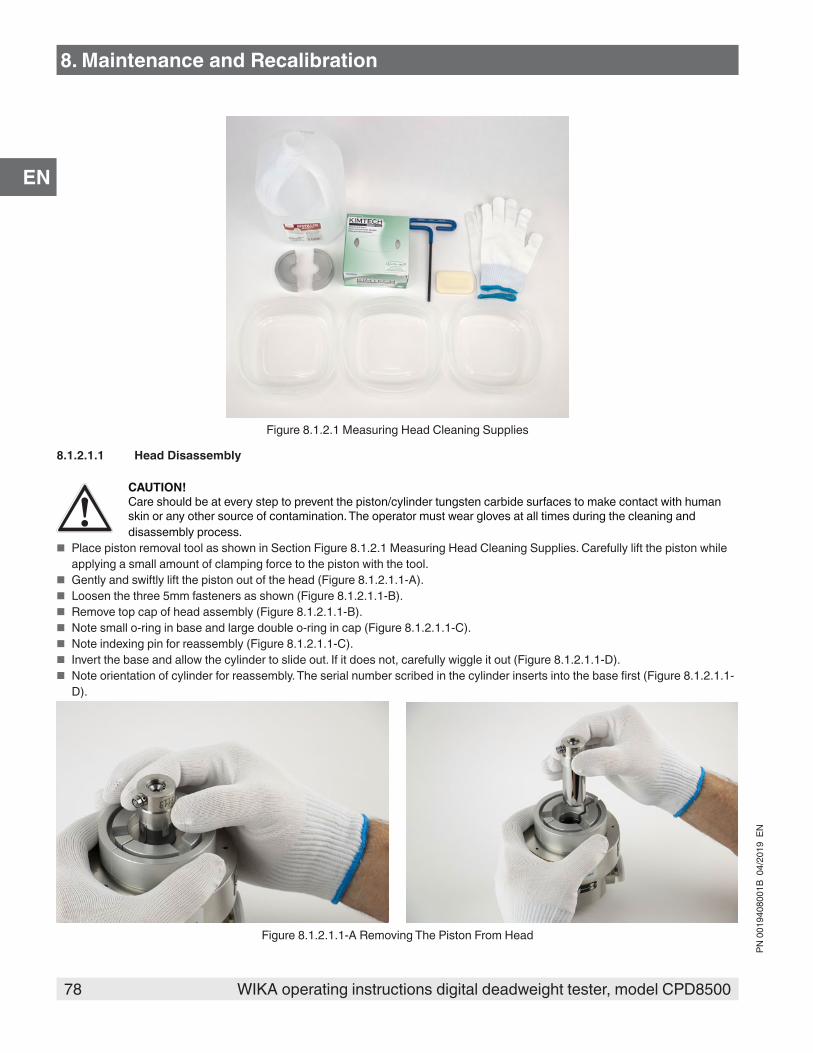
78 WIKA operating instructions digital deadweight tester, model CPD8500
PN 0
0194
0800
1B 0
4/20
19 E
N
EN
Figure 8.1.2.1 Measuring Head Cleaning Supplies
8.1.2.1.1 Head Disassembly
CAUTION!Care should be at every step to prevent the piston/cylinder tungsten carbide surfaces to make contact with human skin or any other source of contamination. The operator must wear gloves at all times during the cleaning and disassembly process.
■ Place piston removal tool as shown in Section Figure 8.1.2.1 Measuring Head Cleaning Supplies. Carefully lift the piston while applying a small amount of clamping force to the piston with the tool.
■ Gently and swiftly lift the piston out of the head (Figure 8.1.2.1.1-A). ■ Loosen the three 5mm fasteners as shown (Figure 8.1.2.1.1-B). ■ Remove top cap of head assembly (Figure 8.1.2.1.1-B). ■ Note small o-ring in base and large double o-ring in cap (Figure 8.1.2.1.1-C). ■ Note indexing pin for reassembly (Figure 8.1.2.1.1-C). ■ Invert the base and allow the cylinder to slide out. If it does not, carefully wiggle it out (Figure 8.1.2.1.1-D). ■ Note orientation of cylinder for reassembly. The serial number scribed in the cylinder inserts into the base first (Figure 8.1.2.1.1-
D).
Figure 8.1.2.1.1-A Removing The Piston From Head
8. Maintenance and Recalibration
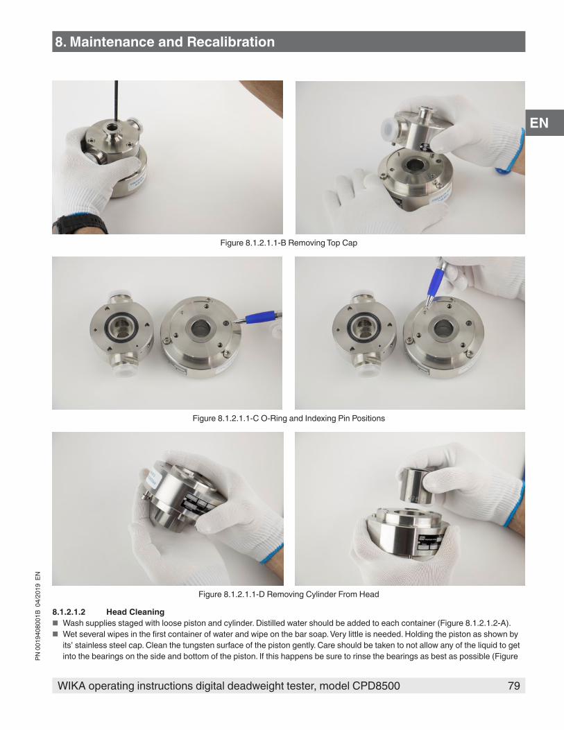
79WIKA operating instructions digital deadweight tester, model CPD8500
PN 0
0194
0800
1B 0
4/20
19 E
N
EN
Figure 8.1.2.1.1-B Removing Top Cap
Figure 8.1.2.1.1-C O-Ring and Indexing Pin Positions
Figure 8.1.2.1.1-D Removing Cylinder From Head
8.1.2.1.2 Head Cleaning ■ Wash supplies staged with loose piston and cylinder. Distilled water should be added to each container (Figure 8.1.2.1.2-A). ■ Wet several wipes in the first container of water and wipe on the bar soap. Very little is needed. Holding the piston as shown by
its’ stainless steel cap. Clean the tungsten surface of the piston gently. Care should be taken to not allow any of the liquid to get into the bearings on the side and bottom of the piston. If this happens be sure to rinse the bearings as best as possible (Figure
8. Maintenance and Recalibration

80 WIKA operating instructions digital deadweight tester, model CPD8500
PN 0
0194
0800
1B 0
4/20
19 E
N
EN
8.1.2.1.2-A) ■ Next carefully rinse in the second bath with different set of wipes keeping the bearings out of the liquid. Repeat this in the third
bath. Carefully dry the piston with dry wipes until all visible liquid is gone (Figure 8.1.2.1.2-B). ■ Wash and rinse the cylinder in the same manner (Figure 8.1.2.1.2-B). ■ The complete cylinder can be submersed for rinsing. Rinse cylinder twice also (Figure 8.1.2.1.2-B). ■ Thorough drying can be accomplished by compressed nitrogen source, canned compressed air or heat gun. Allow parts to
acclimate to ambient temperature conditions before reassembly. If water was introduced into a bearing the piston should be dried using heat.
Figure 8.1.2.1.2-A Piston Cleaning
Figure 8.1.2.1.2-B Cylinder Cleaning
8.1.2.1.3 Head Reassembly ■ Reassemble in reverse order of assembly process. When installing the piston using the removal/insertion tool lightly clamp the
piston with the tool. Allow the piston to drop slowly into place by using less clamping force. ■ The absolute heads 2 and 5 bar would require an insertion tool. A piston removal/insertion tool is not needed for 20 bar range
(Figure 8.1.2.1.3).
8. Maintenance and Recalibration
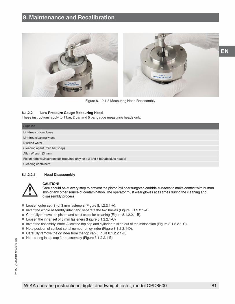
81WIKA operating instructions digital deadweight tester, model CPD8500
PN 0
0194
0800
1B 0
4/20
19 E
N
EN
Figure 8.1.2.1.3 Measuring Head Reassembly
8.1.2.2 Low Pressure Gauge Measuring HeadThese instructions apply to 1 bar, 2 bar and 5 bar gauge measuring heads only.
Supplies
Lint-free cotton glovesLint-free cleaning wipesDistilled waterCleaning agent (mild bar soap)Allen Wrench (3 mm)Piston removal/insertion tool (required only for 1,2 and 5 bar absolute heads)Cleaning containers
8.1.2.2.1 Head Disassembly
CAUTION!Care should be at every step to prevent the piston/cylinder tungsten carbide surfaces to make contact with human skin or any other source of contamination. The operator must wear gloves at all times during the cleaning and disassembly process.
■ Loosen outer set (3) of 3 mm fasteners (Figure 8.1.2.2.1-A). ■ Invert the whole assembly intact and separate the two halves (Figure 8.1.2.2.1-A). ■ Carefully remove the piston and set it aside for cleaning (Figure 8.1.2.2.1-B). ■ Loosen the inner set of 3 mm fasteners (Figure 8.1.2.2.1-C) ■ Invert the assembly intact. Allow the top cap and cylinder to slide out of the midsection (Figure 8.1.2.2.1-C). ■ Note position of scribed serial number on cylinder (Figure 8.1.2.2.1-D). ■ Carefully remove the cylinder from the top cap (Figure 8.1.2.2.1-D). ■ Note o-ring in top cap for reassembly (Figure 8.1.2.2.1-E).
8. Maintenance and Recalibration

82 WIKA operating instructions digital deadweight tester, model CPD8500
PN 0
0194
0800
1B 0
4/20
19 E
N
EN
Figure 8.1.2.2.1-A Separating Measuring Head
Figure 8.1.2.2.1-B Piston Removal
Figure 8.1.2.2.1-C Cylinder With Top Cap
8. Maintenance and Recalibration

83WIKA operating instructions digital deadweight tester, model CPD8500
PN 0
0194
0800
1B 0
4/20
19 E
N
EN
Figure 8.1.2.2.1-D Cylinder Removal
Figure 8.1.2.2.1-E Top Cap O-Ring
8.1.2.2.2 Head CleaningFollow the instructions in Section 8.1.2.1.2 Head Cleaning to clean the piston and cylinder for the gauge measuring head.
8.1.2.2.3 Head ReassemblyReassemble in the reverse order as assembly process.
8.1.2.3 High Pressure Gauge Measuring HeadThese instructions apply to 10 bar up to 500 bar gauge measuring heads only.
Supplies
Lint-free cotton glovesLint-free cleaning wipesDistilled waterCleaning agent (mild bar soap)Allen Wrench (3 mm)Piston removal/insertion tool (required only for 1,2 and 5 bar absolute heads)Cleaning containersHigh range head service kit (Figure 8.1.5)
Figure 8.1.2.3 High Pressure Gauge Service Kit
8. Maintenance and Recalibration
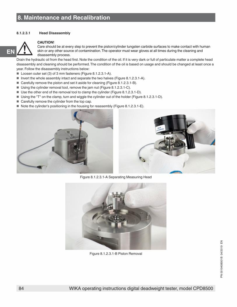
84 WIKA operating instructions digital deadweight tester, model CPD8500
PN 0
0194
0800
1B 0
4/20
19 E
N
EN
8.1.2.3.1 Head Disassembly
CAUTION!Care should be at every step to prevent the piston/cylinder tungsten carbide surfaces to make contact with human skin or any other source of contamination. The operator must wear gloves at all times during the cleaning and disassembly process.
Drain the hydraulic oil from the head first. Note the condition of the oil. If it is very dark or full of particulate matter a complete head disassembly and cleaning should be performed. The condition of the oil is based on usage and should be changed at least once a year. Follow the disassembly instructions below:
■ Loosen outer set (3) of 3 mm fasteners (Figure 8.1.2.3.1-A). ■ Invert the whole assembly intact and separate the two halves (Figure 8.1.2.3.1-A). ■ Carefully remove the piston and set it aside for cleaning (Figure 8.1.2.3.1-B). ■ Using the cylinder removal tool, remove the jam nut (Figure 8.1.2.3.1-C). ■ Use the other end of the removal tool to clamp the cylinder (Figure 8.1.2.3.1-D). ■ Using the "T" on the clamp, turn and wiggle the cylinder out of the holder (Figure 8.1.2.3.1-D). ■ Carefully remove the cylinder from the top cap. ■ Note the cylinder's positioning in the housing for reassembly (Figure 8.1.2.3.1-E).
Figure 8.1.2.3.1-A Separating Measuring Head
Figure 8.1.2.3.1-B Piston Removal
8. Maintenance and Recalibration
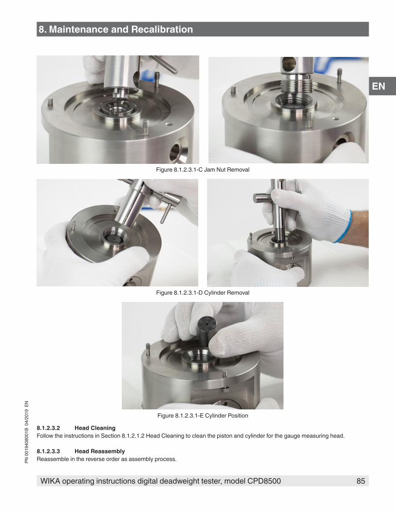
85WIKA operating instructions digital deadweight tester, model CPD8500
PN 0
0194
0800
1B 0
4/20
19 E
N
EN
Figure 8.1.2.3.1-C Jam Nut Removal
Figure 8.1.2.3.1-D Cylinder Removal
Figure 8.1.2.3.1-E Cylinder Position
8.1.2.3.2 Head CleaningFollow the instructions in Section 8.1.2.1.2 Head Cleaning to clean the piston and cylinder for the gauge measuring head.
8.1.2.3.3 Head ReassemblyReassemble in the reverse order as assembly process.
8. Maintenance and Recalibration

86 WIKA operating instructions digital deadweight tester, model CPD8500
PN 0
0194
0800
1B 0
4/20
19 E
N
EN
Following the assembly process, the high pressure gauge heads must be filled with oil. Oil should be filled with the hypodermic needle provided in the kit (Figure 8.1.2.3.3-A). Observe sight glass in front of the head while filling (Figure 8.1.2.3.3-B). Oil level should be about half way. Typically these heads require about 3 - 5 cc of oil. Once oil is filled, cover one of the pressure ports with the threaded adaptor.
Figure 8.1.2.3.3-A Oil Filling Process
Figure 8.1.2.3.3-B Sight Glass
8. Maintenance and Recalibration
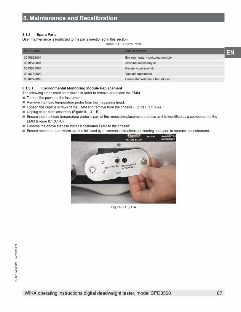
87WIKA operating instructions digital deadweight tester, model CPD8500
PN 0
0194
0800
1B 0
4/20
19 E
N
EN
8.1.3 Spare PartsUser maintenance is restricted to the parts mentioned in this section.
Table 8.1.3 Spare Parts
Part Number Part Description
0019582001 Environmental monitoring module0019540001 Absolute accessory kit0019545001 Gauge accessory kit0018780003 Vacuum transducer0018748003 Barometric reference transducer
8.1.3.1 Environmental Monitoring Module ReplacementThe following steps must be followed in order to remove or replace the EMM
■ Turn off the power to the instrument. ■ Remove the head temperature probe from the measuring head. ■ Loosen the captive screws of the EMM and remove from the chassis (Figure 8.1.3.1-A). ■ Unplug cable from assembly (Figure 8.1.3.1-B). ■ Ensure that the head temperature probe is part of the removal/replacement process as it is identified as a component of the
EMM (Figure 8.1.3.1-C). ■ Reverse the above steps to install a calibrated EMM to the chassis. ■ Ensure recommended warm up time followed by on screen instructions for zeroing and span to operate the instrument.
Figure 8.1.3.1-A
8. Maintenance and Recalibration

88 WIKA operating instructions digital deadweight tester, model CPD8500
PN 0
0194
0800
1B 0
4/20
19 E
N
EN
8. Maintenance and Recalibration
Figure 8.1.3.1-B
Figure 8.1.3.1-C
8.1.3.2 Absolute Accessory Kit ReplacementThe absolute accessory kit and it's components can be removed and replaced. For details on the components see Section 11.3 Absolute Accessory Kit.
8.1.3.3 Gauge Accessory Kit ReplacementThe gauge accessory kit and it's components can be removed and replaced. For details on the components see Section 11.5 Gauge Accessory Kit.
8.1.3.4 Vacuum Transducer ReplacementThe following steps must be followed to remove or replace the vacuum transducer as part of the absolute base.
■ Turn off the power to the instrument and remove the top trim plate by unscrewing three phillips pan-head screws (Figure 8.1.3.4-A).
■ Separate the trim plates and remove the top and bottom parts (Figure 8.1.3.4-A). ■ Remove the top cover by unscrewing the five phillips flat head screws at the rear of the cover (Figure 8.1.3.4-B). ■ Tilt the cover up and slide backwards to remove (Figure 8.1.3.4-B). ■ Locate the vacuum transducer at the bottom right of the chassis and unplug the cable (Figure 8.1.3.4-C). ■ Remove the vacuum flange clamp (Figure 8.1.3.4-C). ■ Loosen the two mounting screws on the back of the transducer (Figure 8.1.3.4-D). ■ Gently remove the vacuum transducer from the chassis (Figure 8.1.3.4-D). ■ Follow these steps backwards to reinstall the vacuum transducer in to the absolute chassis.

89WIKA operating instructions digital deadweight tester, model CPD8500
PN 0
0194
0800
1B 0
4/20
19 E
N
EN
Figure 8.1.3.4-A Trim Plate Removal
Figure 8.1.3.4-B Top Cover Removal
Figure 8.1.3.4-C Unplugging Vacuum Transducer
8. Maintenance and Recalibration

90 WIKA operating instructions digital deadweight tester, model CPD8500
PN 0
0194
0800
1B 0
4/20
19 E
N
EN
Figure 8.1.3.4-D Removing Vacuum Transducer
8.1.3.5 Barometric Reference ReplacementThe following steps must be followed to remove or replace the barometric reference inside the CPD8500 chassis.
■ Follow steps to remove trim plates and top cover (Figure 8.1.3.4-A and Figure 8.1.3.4-B). ■ Locate the barometric reference and unplug the power cable (Figure 8.1.3.5-A). ■ Unscrew the captive screw with a flathead screwdriver (Figure 8.1.3.5-A). ■ Cautiously slide the barometric reference up and out of the chassis (Figure 8.1.3.5-B).
Figure 8.1.3.5-A Disconnecting Barometeric Reference
Figure 8.1.3.5-B Barometeric Reference Removal
8. Maintenance and Recalibration

91WIKA operating instructions digital deadweight tester, model CPD8500
PN 0
0194
0800
1B 0
4/20
19 E
N
EN
8.2 Recalibration8.2.1 Calibration Services by Mensor or WIKA worldwideMensor and WIKA worldwide have extensive experience and knowledge of Mensor products. Calibration of the transducers in these products can be performed at the addresses below or by competent internal or external labs using the procedures in this section.
Table 8.2.1 Service Centers
Service Center USA Service Center Europe
Mensor website: www.mensor.com tel: 1-512-396-4200 1-800-984-4200 fax: 1-512-396-1820 email: [email protected]
WIKA Alexander Wiegand SE & Co. KG website: www.wika.de / www.wika.com tel: (+49) 9372 132-0 fax: (+49) 9372 132-406 email: [email protected]
8.2.2 EnvironmentFor maximum accuracy, allow the CPD8500 to warm up a minimum of 15 minutes in ambient temperature within the compensated range prior to a calibration. In addition, the instrument should be at rest on a stable platform that is free of excessive vibration and shock. It is recommended to wait to the specified warm up time of 4 hours after power on prior to performing calibration.
8.2.2.1 Pressure Calibration Setup for CPD8500
PRESSPRESSURESTANDARD
VACUUM
PRESSURE
SHUT-OFFVALVES
VOLUMECONTROLLER
VENT
LINEREGULATOR
PRESSURESUPPLY
SHUT-OFFVALVES
VENT
METERINGVALVE
Setup for Absolute Pressure
Computer(optional)
RS232, IEEE488, Ethernet, or USB
ABSOLUTECPD8500
REF
VACUUMPUMP
INLET
PRESSUREHEAD FILTER ATM
REFERENCEPORT
REFERENCEPORT
FILTER ATM
NEEDLE VALVE
VACUUM PUMP
8. Maintenance and Recalibration

92 WIKA operating instructions digital deadweight tester, model CPD8500
PN 0
0194
0800
1B 0
4/20
19 E
N
EN
RS232, IEEE488, Ethernet, or USB
PRESSURE
SHUT-OFFVALVE
VOLUMECONTROLLER
VENT
LINEREGULATOR
SHUT-OFFVALVES
VENT
METERINGVALVE
PRESS
REF
PRESSURESTANDARD
PRESSURESUPPLY
Setup for Gauge Pressure
Computer(optional)
INLET
PRESSUREHEAD
GAUGECPD8500
ATMOSPHERE
8.2.3 Pressure StandardsMensor recommends the use of appropriately accurate primary pressure standards when calibrating this instrument. Such standards should be sufficient so that when the techniques of the ISO Guide to the Expression of Uncertainty in Measurement (GUM) are applied, the instrument meets its accuracy statements as required by ISO/IEC 17025:2005, or other applicable standards.8.2.4 MediaThe recommended calibration medium is dry nitrogen or clean dry instrument air for the absolute CPD8500. For the gauge CPD8500, it is recommended to calibrate the measuring head in clean dry air and lubricating the measuring head with recommended lubricating oil mentioned in Section 5.3.2 Gauge Measuring Head. A height variation between the standard and the CPD8500 can cause errors. A calculation should be made to compensate for this difference. This compensation can be done in Section 8.2.8 Head Settings Application.
WARNING!Before proceeding with calibration on any components inside the CPD8500, it is essential to set the Local Gravity. This is a critical parameter for accurate calibration results. Refer to Section 6.1.1 Power Up for detailed instructions.
8.2.5 Calibration DataThe Calibration Data Application is where the calibration data for each component (measurement head, temperature probe, EMM components, optional internal barometer and the internal vacuum sensor) of the instrument is stored and amended. Each calibration data consists of the serial number (S/N) and Pressure Type (if relevant) can be seen in this screen. The date of calibration can be entered by pressing the corresponding button and entering the date with the keypad. Pressing the Check [ ] button confirms the date entry. The certificate name and number can be entered by pressing the corresponding button. This opens a alpha numeric keypad. To save the name of the certificate press [ ]. To revert back to the factory calibration, press the “Restore Factory Cal” button. To view the calibration data for each component press the “Select Device” button at the top and choose a component from the resulting selection menu.
8. Maintenance and Recalibration

93WIKA operating instructions digital deadweight tester, model CPD8500
PN 0
0194
0800
1B 0
4/20
19 E
N
EN
Figure 8.2.5-A Calibration Data App
Figure 8.2.5-B Device Selection (left) and Calibration Certificate Name Entry (right)
8.2.6 Calibration Application
The Calibration Application (Figure 8.2.6-A Calibration App) provides a place to adjust or perform the calibration of the different components inside the CPD8500. Depending on the type of component, it provides the user an option to perform a single point, two point or up to eleven point linearization (Figure 8.2.6-B Calibration Selection Menu). Regardless of the calibration sequence, the type of calibration can be either “As Found” or “Live” and can be accessed within the menu of each calibration sequence. The primary screen in the Calibration App allows the selection of the desired component/device (Measuring head, temperature probe, ambient pressure, ambient temperature, ambient humidity, optional internal barometer and the vacuum sensor) by pressing the corresponding line. After the device selection, a selection for calibration sequence is required. At all times within the Calibration App, the current device and the sequence are indicated at the bottom left of the screen. Pressing the Back [ ] and Next [ ] buttons exit the current calibration routine and move to the previous or next screen respectively.
8. Maintenance and Recalibration
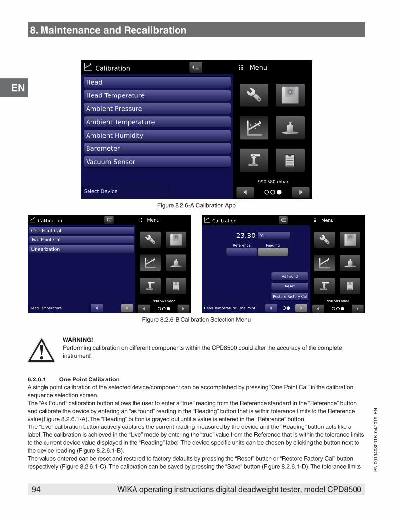
94 WIKA operating instructions digital deadweight tester, model CPD8500
PN 0
0194
0800
1B 0
4/20
19 E
N
EN
Figure 8.2.6-A Calibration App
Figure 8.2.6-B Calibration Selection Menu
WARNING!Performing calibration on different components within the CPD8500 could alter the accuracy of the complete instrument!
8.2.6.1 One Point CalibrationA single point calibration of the selected device/component can be accomplished by pressing “One Point Cal” in the calibration sequence selection screen. The “As Found” calibration button allows the user to enter a “true” reading from the Reference standard in the “Reference” button and calibrate the device by entering an “as found” reading in the “Reading” button that is within tolerance limits to the Reference value(Figure 8.2.6.1-A). The “Reading” button is grayed out until a value is entered in the “Reference” button. The “Live” calibration button actively captures the current reading measured by the device and the “Reading” button acts like a label. The calibration is achieved in the “Live” mode by entering the “true” value from the Reference that is within the tolerance limits to the current device value displayed in the “Reading” label. The device specific units can be chosen by clicking the button next to the device reading (Figure 8.2.6.1-B). The values entered can be reset and restored to factory defaults by pressing the “Reset” button or “Restore Factory Cal” button respectively (Figure 8.2.6.1-C). The calibration can be saved by pressing the “Save” button (Figure 8.2.6.1-D). The tolerance limits
8. Maintenance and Recalibration
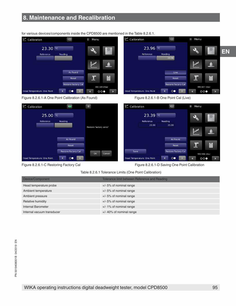
95WIKA operating instructions digital deadweight tester, model CPD8500
PN 0
0194
0800
1B 0
4/20
19 E
N
EN
for various devices/components inside the CPD8500 are mentioned in the Table 8.2.6.1.
Figure 8.2.6.1-A One Point Calibration (As Found) Figure 8.2.6.1-B One Point Cal (Live)
Figure 8.2.6.1-C Restoring Factory Cal Figure 8.2.6.1-D Saving One Point Calibration
Table 8.2.6.1 Tolerance Limits (One Point Calibration)
Device/Component Tolerance limit between Reference and Reading
Head temperature probe +/- 5% of nominal rangeAmbient temperature +/- 5% of nominal rangeAmbient pressure +/- 5% of nominal rangeRelative humidity +/- 5% of nominal rangeInternal Barometer +/- 1% of nominal rangeInternal vacuum transducer +/- 40% of nominal range
8. Maintenance and Recalibration

96 WIKA operating instructions digital deadweight tester, model CPD8500
PN 0
0194
0800
1B 0
4/20
19 E
N
EN
8.2.6.2 Two Point CalibrationA two point calibration of the selected device/component can be accomplished by pressing “Two Point Cal” in the calibration sequence selection screen. A two point calibration is commonly used to adjust the zero and span (sometimes referred to as the offset and slope) of a device. The device specific units can be chosen by clicking the button next to the device reading. The two point calibration can be done either “As Found” or “Live” mode. The modes can be toggled by pressing the “As Found” button on the screen.
Figure 8.2.6.2 Two Point Cal (As Found)
Follow the steps below for a complete Two Point Calibration:To calibrate the “Low Point” in “As Found” mode:
■ Enter the true reference value for low point by pressing the button under “Reference” next to “Low Point” and using the pop up keyboard to the right of the screen. The allowable range for this value is between first point in the range up to 20% of the span of the current device.
■ The button to enter “Reading” is enabled and the adjusted value for device reading can be entered by pressing the “Reading” button next to “Low Point” followed by the check mark [ ]. The Reading value entered must be within the tolerance limits specified in Table 8.2.6.2.
To calibrate the “High point” in “As Found” mode: ■ Enter the true reference value for high point by pressing the button under “Reference” next to “High Point” and using the pop up
keyboard to the right of the screen. The allowable range for this value is between 80% of the span and full scale value of the of the current device.
■ The button to enter “Reading” is enabled and the adjusted value for device reading can be entered by pressing the “Reading” button next to “High Point” followed by the check mark [ ]. The Reading value entered must be within the tolerance limits specified in Table 8.2.6.2.
■ After all four values (high reference, high reading, low reference and low reading) have been entered, the Save button will become active. Press the Save button to accept the calibration data and save it to the memory of the device.
To calibrate the “Low Point” in “Live” mode: ■ The “Reading” button becomes a label and indicates the current measurement from the active device. Apply necessary
pressure, temperature or humidity to allow for a measurement between first point in range up to 20% of the span of the device. ■ Enter the true reference value for low point by pressing the button under “Reference” next to “Low Point” and using the pop up
keyboard to the right of the screen followed by the check mark [ ]. The allowable range for this value must be within the tolerance values defined in Table 8.2.6.2
To calibrate the “High point” in “Live” mode: ■ The “Reading” button indicates the current measurement. Ensure that the measurement is between 80% of the span and full
scale value of the of the current device. ■ Enter the true reference value for high point by pressing the button under “Reference” next to “High Point” and using the pop up
keyboard to the right of the screen followed by the check mark [ ]. The allowable range for this value must be within the
8. Maintenance and Recalibration
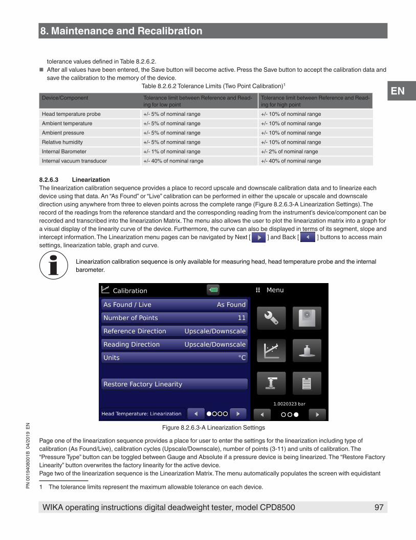
97WIKA operating instructions digital deadweight tester, model CPD8500
PN 0
0194
0800
1B 0
4/20
19 E
N
EN
tolerance values defined in Table 8.2.6.2. ■ After all values have been entered, the Save button will become active. Press the Save button to accept the calibration data and
save the calibration to the memory of the device. Table 8.2.6.2 Tolerance Limits (Two Point Calibration)1
Device/Component Tolerance limit between Reference and Read-ing for low point
Tolerance limit between Reference and Read-ing for high point
Head temperature probe +/- 5% of nominal range +/- 10% of nominal rangeAmbient temperature +/- 5% of nominal range +/- 10% of nominal rangeAmbient pressure +/- 5% of nominal range +/- 10% of nominal rangeRelative humidity +/- 5% of nominal range +/- 10% of nominal rangeInternal Barometer +/- 1% of nominal range +/- 2% of nominal rangeInternal vacuum transducer +/- 40% of nominal range +/- 40% of nominal range
8.2.6.3 LinearizationThe linearization calibration sequence provides a place to record upscale and downscale calibration data and to linearize each device using that data. An “As Found” or “Live” calibration can be performed in either the upscale or upscale and downscale direction using anywhere from three to eleven points across the complete range (Figure 8.2.6.3-A Linearization Settings). The record of the readings from the reference standard and the corresponding reading from the instrument’s device/component can be recorded and transcribed into the linearization Matrix. The menu also allows the user to plot the linearization matrix into a graph for a visual display of the linearity curve of the device. Furthermore, the curve can also be displayed in terms of its segment, slope and intercept information. The Linearization menu pages can be navigated by Next [ ] and Back [ ] buttons to access main settings, linearization table, graph and curve.
Linearization calibration sequence is only available for measuring head, head temperature probe and the internal barometer.
Figure 8.2.6.3-A Linearization Settings
Page one of the linearization sequence provides a place for user to enter the settings for the linearization including type of calibration (As Found/Live), calibration cycles (Upscale/Downscale), number of points (3-11) and units of calibration. The “Pressure Type” button can be toggled between Gauge and Absolute if a pressure device is being linearized. The “Restore Factory Linearity” button overwrites the factory linearity for the active device.Page two of the linearization sequence is the Linearization Matrix. The menu automatically populates the screen with equidistant
1 The tolerance limits represent the maximum allowable tolerance on each device.
8. Maintenance and Recalibration

98 WIKA operating instructions digital deadweight tester, model CPD8500
PN 0
0194
0800
1B 0
4/20
19 E
N
EN
increments from low to high values corresponding to the range of the active device. Each value from the reference standard can be entered under the “Reference” column, corresponding upscale and downscale readings from the device can be entered under the respective “Reading” columns.In “As Found” mode, simply enter the reference & reading values by pressing the number and a keypad will appear where the number can be entered. Press the check mark [ ] to accept each value. Figure 8.2.6.3-B Linearization Matrix (As Found) shows typical linearity values for the head temperature probe. In “Live” mode, simply apply the necessary pressure or temperature to reach the nominal linearity point and then add enter the “true” reference value in the corresponding “Reference” cell. Press the check mark [ ] to accept each value. The values must be within the tolerance limits of each other to be accepted.The tolerance limits between reference and reading values can be found in Table 8.2.6.3.
Figure 8.2.6.3-B Linearization Matrix (As Found)
WARNING!Exiting the Linearization Matrix without completing or saving all the values in the matrix results in all changes being lost.
Page three of the linearization sequence displays the Linearization Graph. This gives a visual representation of the errors associated with the values entered in the Linearization Table. This Linearization error graph shows a scaling that corresponds to the maximum error calculated from the data entered in the Linearization Matrix. It is a good indication of the overall error of the device, and will quickly reveal any gross data entry errors that have been made. When satisfied that all values have been entered correctly, press the “Adjust” button and then the “Save” button to save the new calibration data in the device or instrument memory (Figure 8.2.6.3-C Linearization Graph).
Table 8.2.6.3 Tolerance Limits (Linearization)
Device/Component Tolerance limit between Reference and Reading
Measuring head +/- 0.5% of nominal rangeHead temperature probe +/- 1% of nominal rangeInternal Barometer +/- 0.5% of nominal range
8. Maintenance and Recalibration
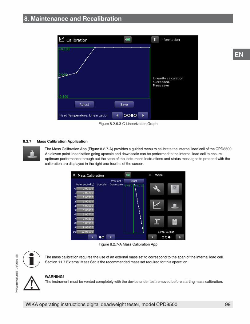
99WIKA operating instructions digital deadweight tester, model CPD8500
PN 0
0194
0800
1B 0
4/20
19 E
N
EN
Figure 8.2.6.3-C Linearization Graph
8.2.7 Mass Calibration Application
The Mass Calibration App (Figure 8.2.7-A) provides a guided menu to calibrate the internal load cell of the CPD8500. An eleven point linearization going upscale and downscale can be performed to the internal load cell to ensure optimum performance through out the span of the instrument. Instructions and status messages to proceed with the calibration are displayed in the right one-fourths of the screen.
Figure 8.2.7-A Mass Calibration App
The mass calibration requires the use of an external mass set to correspond to the span of the internal load cell. Section 11.7 External Mass Set is the recommended mass set required for this operation.
WARNING!The instrument must be vented completely with the device under test removed before starting mass calibration.
8. Maintenance and Recalibration
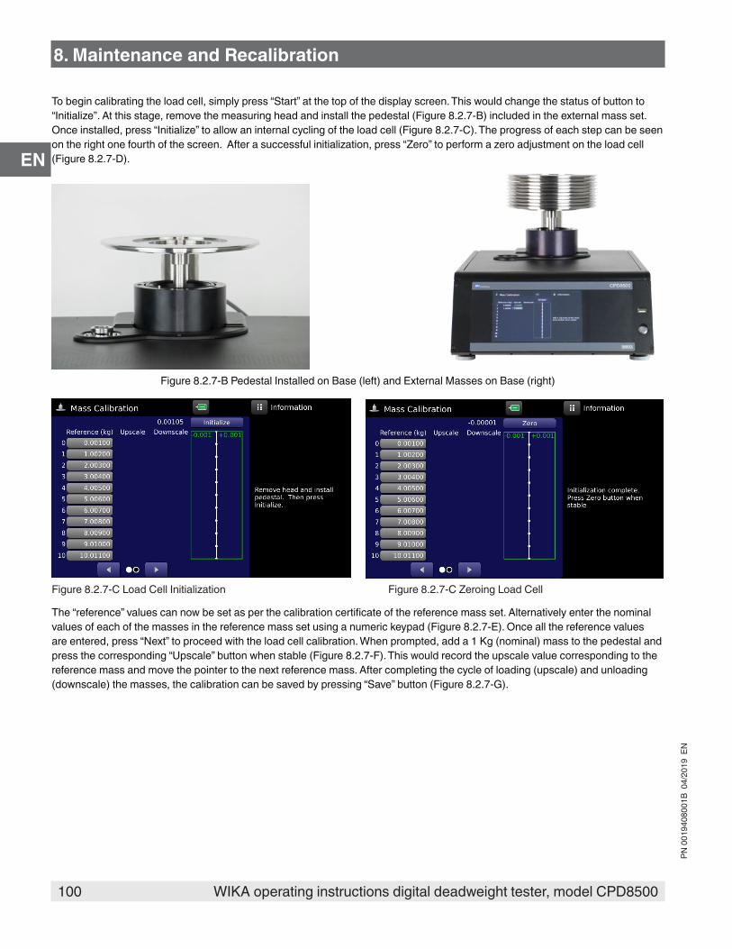
100 WIKA operating instructions digital deadweight tester, model CPD8500
PN 0
0194
0800
1B 0
4/20
19 E
N
EN
To begin calibrating the load cell, simply press “Start” at the top of the display screen. This would change the status of button to “Initialize”. At this stage, remove the measuring head and install the pedestal (Figure 8.2.7-B) included in the external mass set. Once installed, press “Initialize” to allow an internal cycling of the load cell (Figure 8.2.7-C). The progress of each step can be seen on the right one fourth of the screen. After a successful initialization, press “Zero” to perform a zero adjustment on the load cell (Figure 8.2.7-D).
Figure 8.2.7-B Pedestal Installed on Base (left) and External Masses on Base (right)
Figure 8.2.7-C Load Cell Initialization Figure 8.2.7-C Zeroing Load Cell
The “reference” values can now be set as per the calibration certificate of the reference mass set. Alternatively enter the nominal values of each of the masses in the reference mass set using a numeric keypad (Figure 8.2.7-E). Once all the reference values are entered, press “Next” to proceed with the load cell calibration. When prompted, add a 1 Kg (nominal) mass to the pedestal and press the corresponding “Upscale” button when stable (Figure 8.2.7-F). This would record the upscale value corresponding to the reference mass and move the pointer to the next reference mass. After completing the cycle of loading (upscale) and unloading (downscale) the masses, the calibration can be saved by pressing “Save” button (Figure 8.2.7-G).
8. Maintenance and Recalibration
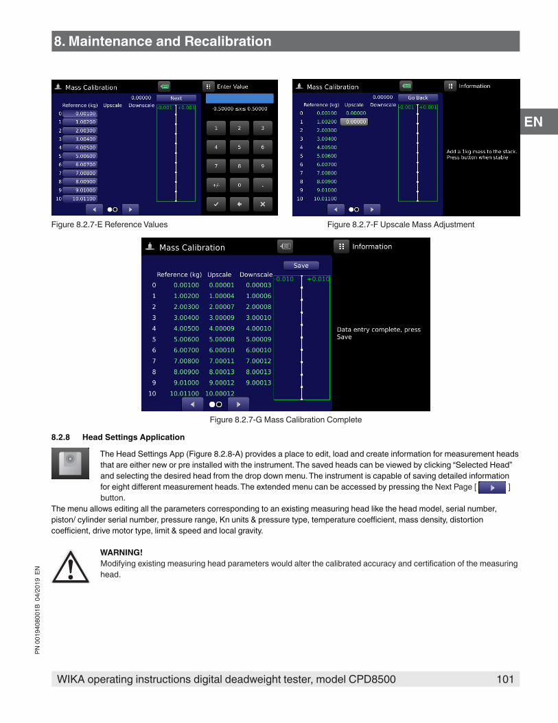
101WIKA operating instructions digital deadweight tester, model CPD8500
PN 0
0194
0800
1B 0
4/20
19 E
N
EN
Figure 8.2.7-E Reference Values Figure 8.2.7-F Upscale Mass Adjustment
Figure 8.2.7-G Mass Calibration Complete
8.2.8 Head Settings Application
The Head Settings App (Figure 8.2.8-A) provides a place to edit, load and create information for measurement heads that are either new or pre installed with the instrument. The saved heads can be viewed by clicking “Selected Head” and selecting the desired head from the drop down menu. The instrument is capable of saving detailed information for eight different measurement heads. The extended menu can be accessed by pressing the Next Page [ ] button.
The menu allows editing all the parameters corresponding to an existing measuring head like the head model, serial number, piston/ cylinder serial number, pressure range, Kn units & pressure type, temperature coefficient, mass density, distortion coefficient, drive motor type, limit & speed and local gravity.
WARNING!Modifying existing measuring head parameters would alter the calibrated accuracy and certification of the measuring head.
8. Maintenance and Recalibration
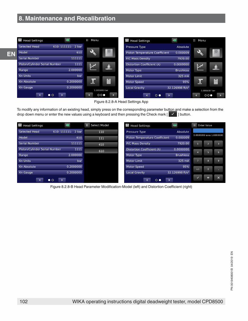
102 WIKA operating instructions digital deadweight tester, model CPD8500
PN 0
0194
0800
1B 0
4/20
19 E
N
EN
Figure 8.2.8-A Head Settings App
To modify any information of an existing head, simply press on the corresponding parameter button and make a selection from the drop down menu or enter the new values using a keyboard and then pressing the Check mark [ ] button.
Figure 8.2.8-B Head Parameter Modification-Model (left) and Distortion Coefficient (right)
8. Maintenance and Recalibration

103WIKA operating instructions digital deadweight tester, model CPD8500
PN 0
0194
0800
1B 0
4/20
19 E
N
EN
8.2.8.1 New Head Addition
Note: It is advised that the user enters new Measurement Head data using a USB installation as opposed to the Head Settings App. The App should be used when Head Information can not be loaded from the USB.
To add a new Measuring Head to the instrument, simply click the “Selected Head” button and select “Create” in the drop down menu. This modifies the Head Settings App to indicate mandatory parameter entry with the parameter highlighted in red enter the type of the measuring head (Figure 8.2.8.1-A). All the mandatory parameter are located on the page one of the Head Settings App and the information needed to create them can be obtained from either the calibration certificate of the measuring head or the head label. Parameters like the Serial number, Piston/ cylinder serial number, Measurement range, Piston temperature coefficient, P/C mass density and Distortion coefficient can be entered by entering the new value with the numeric keypad while parameters like Model, Kn Units and Motor type are selected from a drop down menu. The Kn Absolute and Gauge are automatically calculated once all the highlighted information is entered. The user can modify these to represent the values calculated in the calibration certificate.
Figure 8.2.8.1-A Head Creation
Once all the necessary information is entered, the Save button becomes active and the head parameters can be saved to the memory of the CPD8500. Pressing the “Save” button prompts “Create new head data file?” on the screen and pressing OK [ ] button creates the new head file with the above data. (Figure 8.2.8.1-B).
Figure 8.2.8.1-B Save Head File
8. Maintenance and Recalibration
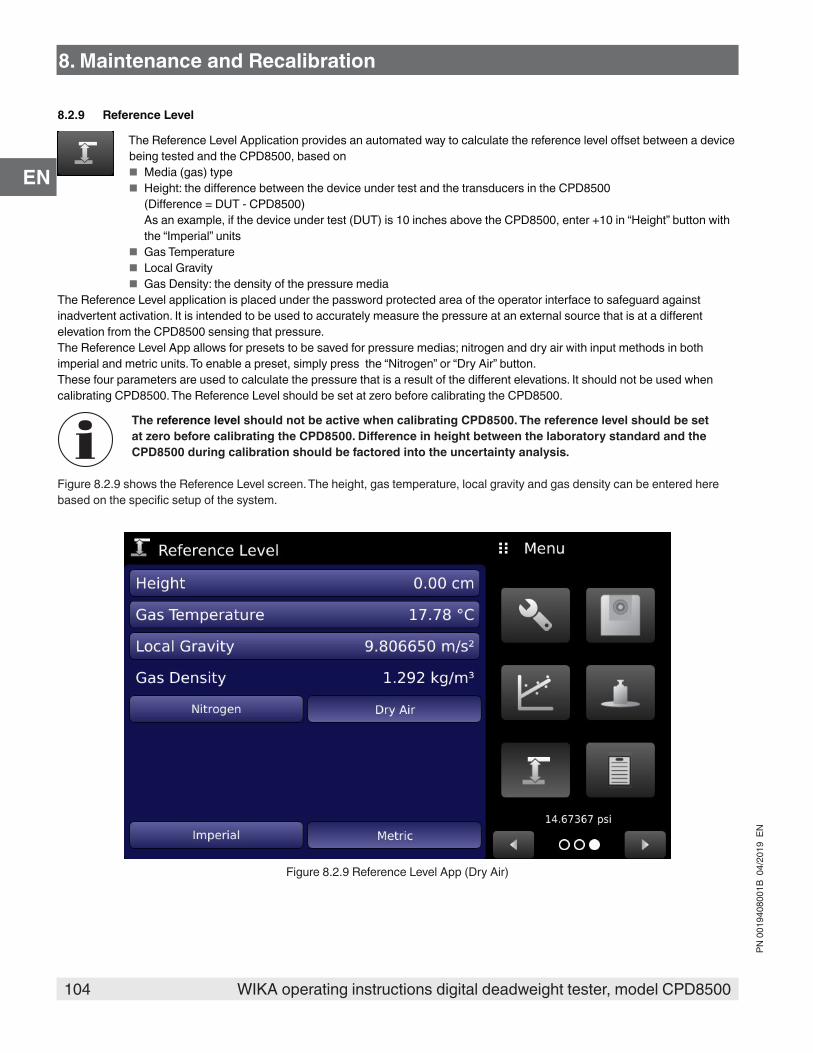
104 WIKA operating instructions digital deadweight tester, model CPD8500
PN 0
0194
0800
1B 0
4/20
19 E
N
EN
8.2.9 Reference Level
The Reference Level Application provides an automated way to calculate the reference level offset between a device being tested and the CPD8500, based on
■ Media (gas) type ■ Height: the difference between the device under test and the transducers in the CPD8500
(Difference = DUT - CPD8500) As an example, if the device under test (DUT) is 10 inches above the CPD8500, enter +10 in “Height” button with the “Imperial” units
■ Gas Temperature ■ Local Gravity ■ Gas Density: the density of the pressure media
The Reference Level application is placed under the password protected area of the operator interface to safeguard against inadvertent activation. It is intended to be used to accurately measure the pressure at an external source that is at a different elevation from the CPD8500 sensing that pressure. The Reference Level App allows for presets to be saved for pressure medias; nitrogen and dry air with input methods in both imperial and metric units. To enable a preset, simply press the “Nitrogen” or “Dry Air” button. These four parameters are used to calculate the pressure that is a result of the different elevations. It should not be used when calibrating CPD8500. The Reference Level should be set at zero before calibrating the CPD8500.
The reference level should not be active when calibrating CPD8500. The reference level should be set at zero before calibrating the CPD8500. Difference in height between the laboratory standard and the CPD8500 during calibration should be factored into the uncertainty analysis.
Figure 8.2.9 shows the Reference Level screen. The height, gas temperature, local gravity and gas density can be entered here based on the specific setup of the system.
Figure 8.2.9 Reference Level App (Dry Air)
8. Maintenance and Recalibration

105WIKA operating instructions digital deadweight tester, model CPD8500
PN 0
0194
0800
1B 0
4/20
19 E
N
EN
9. Dismounting, Return and Disposal
WARNING!Physical injuries and damage to property and the environment through residual mediaResidual media in the dismounted instrument can result in a risk to persons, the environment and equipment.
▶ Wear the requisite protective equipment (see Section 3.6 Personal Protective Equipment). ▶ Observe the information in the material safety data sheet for the corresponding medium. ▶ Wash or clean the dismounted instrument, in order to protect persons and the environment from exposure to residual media.
9.1 Dismounting
WARNING!Physical injuries and damage to property and the environment through residual mediaUpon contact with hazardous media (e.g. oxygen, acetylene, flammable or toxic substances), harmful media (e.g. corrosive, toxic, carcinogenic, radioactive), and also with refrigeration plants and compressors, there is a danger of physical injuries and damage to property and the environment.
▶ Before storage of the dismounted instrument (following use) wash or clean it, in order to protect persons and the environment from exposure to residual media.
▶ Wear the requisite protective equipment (see Section 3.6 Personal Protective Equipment). ▶ Observe the information in the material safety data sheet for the corresponding medium.
WARNING!Risk of burnsDuring dismounting there is a risk of dangerously hot media escaping.
▶ Let the instrument cool down sufficiently before dismounting it!
DANGER!Danger to life caused by electric currentUpon contact with live parts, there is a direct danger to life.
▶ The dismounting of the instrument may only be carried out by skilled personnel.
WARNING!Physical injuryWhen dismounting, there is a danger from aggressive media and high pressures.
▶ Wear the requisite protective equipment (see Section 3.6 Personal Protective Equipment). ▶ Observe the information in the material safety data sheet for the corresponding medium. ▶ Only disconnect the pressure measuring instrument/measuring assembly/test and calibration installations once the system has been depressurized.
9. Dismounting, Return and Disposal
106 WIKA operating instructions digital deadweight tester, model CPD8500
PN 0
0194
0800
1B 0
4/20
19 E
N
EN
9.2 Return
Strictly observe the following when shipping the instrument:All instruments delivered to Mensor must be free from any kind of hazardous substances (acids, bases, solutions, etc.) must therefore be cleaned before being returned.
WARNING!Physical injuries and damage to property and the environment through residual mediaResidual media in the dismounted instrument can result in a risk to persons, the environment and equipment.
▶ With hazardous substances, include the material safety data sheet for the corresponding medium..
When returning the instrument, use the original packaging or a suitable transport packaging.
To avoid damage:1. Wrap the instrument in an anti static plastic film.2. Place the instrument in the same packaging as it arrived. See Section 4. Transport, Packaging and Storage for details.3. Label the shipment/ carrying case as carriage of a highly sensitive measuring instrument.
Information on returns can be found under the heading “Service” on our local website.
9.3 DisposalIncorrect disposal can put the environment at risk.Dispose of instrument components and packaging materials in an environmentally compatible way and in accordance with the country-specific waste disposal regulations.
This marking on the instruments indicates that they must not be disposed of in domestic waste. The disposal is carried out by return to the manufacturer or by the corresponding municipal authorities.
9. Dismounting, Return and Disposal

107WIKA operating instructions digital deadweight tester, model CPD8500
PN 0
0194
0800
1B 0
4/20
19 E
N
EN
10. SpecificationsAccuracy specifications presented herein are obtained by comparison with primary standards traceable to a national metrology institute or recognized international standard organization. These specifications are obtained in accordance with the ISO Guide to the Expression of Uncertainty in Measurement (GUM). The calibration program at Mensor is accredited by the American Association of Laboratory Accreditation (A2LA) as complying with both the ISO/IEC 17025:2005 and the ANSI/NCSL Z540-1-1994 standards. If there is an exception to the requirements and recommendations of Z540 during a calibration the exception is noted on the individual calibration certificate.Mensor reserves the right to change specifications without notice.
10.1 Measuring Head
Measuring head including the piston cylinder system model CPS8500Pressure range Piston cylinder system Kn 1) Lubrication media
Absolute pressure0 ... 2 bar (0 ... 29 psi) 0.2 bar/ kg (2.9 psi / kg)
Dry, clean air or nitrogen
0 ... 5 bar (0 ... 72.5 psi) 0.5 bar / kg (7.25 psi / kg)0 ... 10 bar (0 ... 145 psi) 1 bar / kg (14.5 psi / kg)0 ... 20 bar (0 ... 290 psi) 2 bar / kg (29 psi / kg)
Gauge pressure0 ... 1 bar (0 ... 14.5 psi) 0.1 bar / kg (1.45 psi / kg)
Dry, clean air or nitrogen0 ... 2 bar (0 ... 29 psi) 0.2 bar/ kg (2.9 psi/ kg)0 ... 5 bar (0 ... 72.5 psi) 0.5 bar / kg (7.25 psi / kg)0 ... 10 bar (0 ... 145 psi) 1 bar / kg (14.5 psi / kg) Dry, clean air or nitrogen over Drosera oil0 ... 20 bar (0 ... 290 psi) 2 bar / kg (29 psi / kg)
Dry, clean air or nitrogen over Sebacate oil
0 ... 50 bar (0 ... 725 psi) 5 bar / kg (72.5 psi / kg)0 ... 100 bar (0 ... 1,450 psi) 10 bar / kg (145 psi / kg)0 ... 200 bar (0 ... 2,900 psi) 20 bar / kg (290 psi / kg)0 ... 500 bar (0 ... 7,250 psi) 50 bar / kg (725 psi / kg)Calibration interval 5 years
Permissible pressurePermissible pressure media Dry, clean air or nitrogen (ISO 8573-1:2010 class 5.5.4 or better)Maximum pressure 100% FS of the measuring head
ConnectionsPressure port adapters (0 ... 2 bar abs. & 0 ... 5 bar abs.)
Standard: KF16 flange; Standard with coalescing filter: 1/8” NPT female Additional: KF16 to DH1500
Pressure port adapters (Gauge & 0 ... 10 bar abs., 0 ... 20 bar abs.)
Standard: DH1500 port Additional: DH1500 to 7/16-20 SAE female
Wetted parts 2017 AL, 2024 AL, 303 SS, 304 SS, 316 SS, Tungsten Carbide, Sapphire, Buna N, FKM/ FPM, Silicone grease, Drosera oil, Sebacate oil, Urethane
Filter elements (0 ... 2 bar abs. & 0 ... 5 bar abs.)
The instrument has a 0.01 micron filter to prevent contamination
1) Kn is defined as the piston cylinder coefficient determining the pressure generated per kilogram of mass exerted on the CPD8500 chassis.
10. Specifications

108 WIKA operating instructions digital deadweight tester, model CPD8500
PN 0
0194
0800
1B 0
4/20
19 E
N
EN
10.2 Base Instrument
Base instrumentInstrument
Instrument version Desktop caseDimensions See technical drawingsWeight Absolute: approx. 23.5 kg (52 lbs) incl. all internal options without measuring head
Gauge: approx. 15 kg (33 lbs) incl. all internal options without measuring headWarm-up time Up to 4 hours to rated accuracyStandard accuracy 2) 3) 50 ppm 5)
Premium accuracy 4) 35 ppm (compatible only with absolute and gauge CPS8500 up to 20 bar/290 psi)Calibration interval 365 days
DisplayScreen 7.0" color LCD with resistive touchscreenResolution 5 ... 8 digits depending on range and units
ConnectionsPressure connections (Reference port/ Vacuum port)
Absolute: 2 ports with KF16 flanges
Barometer port adapters 10-32 tapped port with 5/32 barb fittingWetted parts 2017 AL, 2024 AL, 304 SS, 316 SS, Nickel, Buna N, FKM/ FPM, Silicone grease, Christo Lube MCG
1030, Urethane, PCTFEPermissible pressure
Reference port/ Vacuum port 2 Pa ... 100 kPa abs. (15 mTorr ... 750 Torr abs.)Voltage supply
Power supply AC 100 ... 120 V, 50/60 Hz; AC 220 ... 240 V, 50/60 HzPower consumption max. 50 VA
Permissible ambient conditionsStorage temperature -20 ... 70 °C (-4 ... 158 °F)Humidity 5 … 95% r. h. (relative humidity non-condensing)Compensated temperature range 15 ... 40 °C (59 ... 104 °F)Mounting position HorizontalAltitude max. 3,048 metersShock/ Vibration max. 2 G
Environmental monitoring module & Head temperatureSensor Range Accuracy 2)
Head temperature sensor 0 ... 50 °C (32 ... 122 °F) 0.5 °CAmbient temperature sensor -40 ... 125 °C (- 40 ... 257 °F) 1.0 °CRelative humidity sensor 0 ... 100% 5% of relative humidityAmbient pressure sensor 552 ... 1,170 mbar abs (8 ... 17 psi abs) 2% of readingCalibration interval 365 days
Residual vacuumSensor Range Accuracy 2)
High accuracy vacuum sensor 0.1 ... 1000 mtorr 0.4% of readingCalibration interval 365 days
CommunicationInterface Standard: Ethernet, IEEE-488, USB, RS-232.Command sets Mensor and CPD8000
10. Specifications
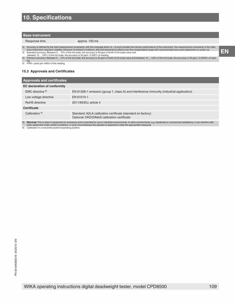
109WIKA operating instructions digital deadweight tester, model CPD8500
PN 0
0194
0800
1B 0
4/20
19 E
N
EN
Base instrumentResponse time approx. 100 ms
2) Accuracy is defined by the total measurement uncertainty, with the coverage factor (k = 2) and includes the intrinsic performance of the instrument, the measurement uncertainty of the refer-ence instrument, long-term stability, influence of ambient conditions, drift and temperature effects over the compensated range with recommended zero point adjustment on power up.
3) Standard accuracy: Between 0 ... 10% of the full scale, the accuracy is 50 ppm of tenth of full scale value and between 10 ... 100% of the full scale, the accuracy is 50 ppm / 0.005% of reading
4) Premium accuracy: Between 0 ... 10% of the full scale, the accuracy is 35 ppm of tenth of full scale value and between 10 ... 100% of the full scale, the accuracy is 35 ppm / 0.0035% of read-ing
5) PPM = parts per million of the reading.
10.3 Approvals and Certificates
Approvals and certificatesEC declaration of conformity
EMC directive 8) EN 61326-1 emission (group 1, class A) and interference immunity (industrial application)Low voltage directive EN 61010-1RoHS directive 2011/65/EU, article 4
CertificateCalibration 9) Standard: A2LA calibration certificate (standard on factory)
Optional: DKD/DAkkS calibration certificate8) Warning! This is class A equipment for emissions and is intended for use in industrial environments. In other environments, e.g. residential or commercial installations, it can interfere with
other equipment under certain conditions. In such circumstances the operator is expected to take the appropriate measures.9) Calibration in a horizontal position/operating position.
10. Specifications

110 WIKA operating instructions digital deadweight tester, model CPD8500
PN 0
0194
0800
1B 0
4/20
19 E
N
EN
10.4 Dimensions in mm (in)10.4.1 Absolute
[ 395 ]15.553
[ 345.4 ]13.600
[ 345.4 ]13.600
10. Specifications

111WIKA operating instructions digital deadweight tester, model CPD8500
PN 0
0194
0800
1B 0
4/20
19 E
N
EN
10.4.2 Gauge
[ 302.1 ]11.893
[ 345.4 ]13.600
345.413.600
[ 536.7 ]21.129
[ 200.9 ]7.909 6.925
[ 175.9 ]
10. Specifications

112 WIKA operating instructions digital deadweight tester, model CPD8500
PN 0
0194
0800
1B 0
4/20
19 E
N
EN
11. Accessories ■ Barometric reference sensor (for pressure emulation) ■ Vacuum transducer ■ Absolute accessory kit ■ Vacuum pump requirements ■ Gauge accessory kit ■ Upgrade accessory kit ■ External mass set ■ EMM calibration sled ■ Barometric reference calibration sled
11.1 Barometric Reference SensorThe CPD8500 can be ordered with an internal barometric reference sensor. It is a very stable, absolute pressure transducer, used to accurately measure local atmospheric pressure. It is used to display the barometric pressure (reading appears on the bottom right side of the display) or as a barometric reference for bidirectional emulation. The barometric reference sensor is installed inside the CPD8500 base.
11.1.1 Bidirectional Pressure EmulationIn the Home Application (main screen) a gauge instrument will indicate “Gauge” in the Pressure Type button (this is the default mode). When the Pressure Type button is pressed a selection screen will appear to choose between Absolute, Bidirectional and Gauge. If bidirectional is chosen, the button turns yellow. This change in color is an indication that the instrument is in emulation mode. This change in color is an indication that the instrument is in emulation mode.In the absolute emulation mode the atmospheric pressure reading from the barometric reference transducer is added to the gauge pressure reading of the instrument to emulate an absolute pressure. The instrument is only able to emulate absolute pressures above atmospheric pressure. Sub-atmospheric measurement is not possible.
11.1.2 Emulation Mode AccuracyThe accuracy in emulation mode is different than native mode.The barometric reference has six significant digits and has a guaranteed drift of 0.0000041 psi over a 24 hour period. The absolute uncertainty of the barometric reference must be considered in the bidirectional pressure uncertainty.
11.1.3 Barometric Reference CalibrationThe Barometric Reference Transducer can be calibrated in exactly the same manner as the other installed components as described in Section 8.2 Recalibration. Alternatively the barometric reference can be calibrated outside of the instrument using a calibration sled or adapter (Section 11.9 Barometric Reference Calibration Sled).
11.2 Vacuum TransducerThe vacuum transducer is installed inside the absolute CPD8500 base. The vacuum transducer is used inside the instrument to measure residual pressure inside the reference chamber, when performing absolute mode measurements. The vacuum transducer is a highly stable vacuum transducer which enables performing a Zero calibration on the absolute CPD8500. Figure 11.2 shows the vacuum transducer outside the instrument.
Figure 11.2 Vacuum Transducer
11. Accessories
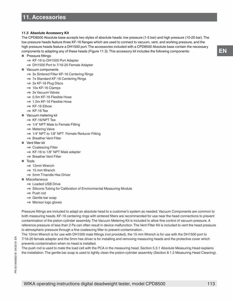
113WIKA operating instructions digital deadweight tester, model CPD8500
PN 0
0194
0800
1B 0
4/20
19 E
N
EN
11.3 Absolute Accessory KitThe CPD8500 Absolute base accepts two styles of absolute heads: low pressure (1-5 bar) and high pressure (10-20 bar). The low pressure heads feature three KF-16 flanges which are used to connect to vacuum, vent, and working pressure, and the high pressure heads feature a DH1500 port. The accessories included with a CPD8500 Absolute base contain the necessary components to adapting any of these heads (Figure 11.3). This accessory kit includes the following components:
■ Pressure fittings ⇒ KF-16 to DH1500 Port Adapter ⇒ DH1500 Port to 7/16-20 Female Adapter
■ Vacuum components ⇒ 3x Sintered Filter KF-16 Centering Rings ⇒ 7x Standard KF-16 Centering Rings ⇒ 3x KF-16 Plug Discs ⇒ 10x KF-16 Clamps ⇒ 3x Vacuum Valves ⇒ 0.5m KF-16 Flexible Hose ⇒ 1.0m KF-16 Flexible Hose ⇒ KF-16 Elbow ⇒ KF-16 Tee
■ Vacuum metering kit ⇒ KF-16/NPT Tee ⇒ 1/4” NPT Male to Female Fitting ⇒ Metering Valve ⇒ 1/4” NPT to 1/8” NPT Female Reducer Fitting ⇒ Breather Vent Filter
■ Vent filter kit ⇒ Coalescing Filter ⇒ KF-16 to 1/8" NPT Male adapter ⇒ Breather Vent Filter
■ Tools ⇒ 12mm Wrench ⇒ 15 mm Wrench ⇒ 5mm T-handle Hex Driver
■ Miscellaneous ⇒ Loaded USB Drive ⇒ Silicone Tubing for Calibration of Environmental Measuring Module ⇒ Push rod ⇒ Gentle bar soap ⇒ Mensor logo gloves
Pressure fittings are included to adapt an absolute head to a customer’s system as needed. Vacuum Components are common to both measuring heads. KF-16 centering rings with sintered filters are recommended for use near the head connections to prevent contamination of the piston-cylinder assembly. The Vacuum Metering Kit is included to allow fine control of vacuum pressure. A reference pressure of less than 2 Pa can often result in device malfunction. The Vent Filter Kit is included to vent the head pressure to atmospheric pressure through a fine coalescing filter to prevent contamination. .The 12mm Wrench is for use with DH1500 male fittings (not provided), the 15 mm Wrench is for use with the DH1500 port to 7/16-20 female adapter and the 5mm hex driver is for installing and removing measuring heads and the protective cover which prevents contamination when no head is installed.The push rod is used to mate the load cell with the PCA in the measuring head. Section 5.3.1 Absolute Measuring Head explains the installation. The gentle bar soap is used to lightly clean the piston-cylinder assembly (Section 8.1.2 Measuring Head Cleaning).
11. Accessories
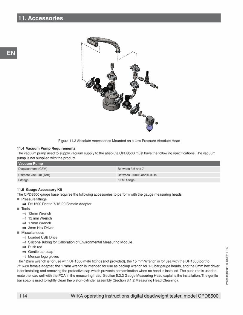
114 WIKA operating instructions digital deadweight tester, model CPD8500
PN 0
0194
0800
1B 0
4/20
19 E
N
EN
Figure 11.3 Absolute Accessories Mounted on a Low Pressure Absolute Head
11.4 Vacuum Pump RequirementsThe vacuum pump used to supply vacuum supply to the absolute CPD8500 must have the following specifications. The vacuum pump is not supplied with the product.Vacuum PumpDisplacement (CFM) Between 3.6 and 7
Ultimate Vacuum (Torr) Between 0.0005 and 0.0015Fittings KF16 flange
11.5 Gauge Accessory KitThe CPD8500 gauge base requires the following accessories to perform with the gauge measuring heads:
■ Pressure fittings ⇒ DH1500 Port to 7/16-20 Female Adapter
■ Tools ⇒ 12mm Wrench ⇒ 15 mm Wrench ⇒ 17mm Wrench ⇒ 3mm Hex Driver
■ Miscellaneous ⇒ Loaded USB Drive ⇒ Silicone Tubing for Calibration of Environmental Measuring Module ⇒ Push rod ⇒ Gentle bar soap ⇒ Mensor logo gloves
The 12mm wrench is for use with DH1500 male fittings (not provided), the 15 mm Wrench is for use with the DH1500 port to 7/16-20 female adapter, the 17mm wrench is intended for use as backup wrench for 1-5 bar gauge heads, and the 3mm hex driver is for installing and removing the protective cap which prevents contamination when no head is installed. The push rod is used to mate the load cell with the PCA in the measuring head. Section 5.3.2 Gauge Measuring Head explains the installation. The gentle bar soap is used to lightly clean the piston-cylinder assembly (Section 8.1.2 Measuring Head Cleaning).
11. Accessories

115WIKA operating instructions digital deadweight tester, model CPD8500
PN 0
0194
0800
1B 0
4/20
19 E
N
EN
11.6 Upgrade Accessory KitWhen upgrading an existing CPD8000 to a new CPD8500, the new absolute instrument requires a few accessories that are different than the accessories being used for the CPD8000:
■ Pressure fittings ⇒ DH1500 Port to 7/16-20 Female Adapter
■ Vacuum components ⇒ 3x Sintered Filter KF-16 Centering Rings
■ Tools ⇒ 12mm Wrench ⇒ 15 mm Wrench ⇒ 5mm T-handle Hex Driver
■ Miscellaneous ⇒ Loaded USB Drive ⇒ Silicone Tubing for Calibration of Environmental Measuring Module ⇒ Push rod ⇒ Gentle bar soap ⇒ Mensor logo gloves
The 12mm wrench is for use with DH1500 male fittings (not provided), the 15 mm Wrench is for use with the DH1500 port to 7/16-20 female adapter and the 3mm hex driver is for installing and removing the protective cap which prevents contamination when no head is installed. KF-16 centering rings with sintered filters are recommended for use near the head connections to prevent contamination of the piston-cylinder assembly.
11.7 External Mass SetAn External Mass Set is required to calibrate and linearize the internal load cell to the CPD8500 (See Section 8.2.7 Mass Calibration Application for details). The mass set (Figure 11.7) contains the following:
■ Mounting connector ■ Pedestal ■ 10 x 1 Kg masses ■ Mensor logo gloves
The mounting connector mates the internal load cell to the external masses and the pedestal. The mounting connector is installed directly on the push rod on top of the instrument to transfer the weight of the masses on to the load cell. The pedestal is required to provide a support to the individual masses. Then simply follow the instructions in Section 8.2.7 Mass Calibration Application to linearize the load cell.
11. Accessories

116 WIKA operating instructions digital deadweight tester, model CPD8500
PN 0
0194
0800
1B 0
4/20
19 E
N
EN
Figure 11.7 External Mass Set in Carrying Case
11.8 EMM Calibration SledThe Environmental Monitoring Module (EMM) can be calibrated both inside and outside the instrument. For detailed instructions on calibrating the EMM inside CPD8500, follow instructions in Section 8.2.6 Calibration Application.To calibrate the EMM outside the CPD8500, a calibration sled or adapter is required for the EMM to communicate with a computer. The primary function of the calibration sled is to allow communication of the sled via RS-232 port. The calibration can be done by reading the EMM remotely by the PC and comparing the values of each sub component with the reference standard. The calibration sled also requires a 12 V DC power source.
Figure 11.6 EMM Calibration Sled
The calibration sled software along with detailed instructions on setup and calibration can be found on the Mensor website.
11. Accessories
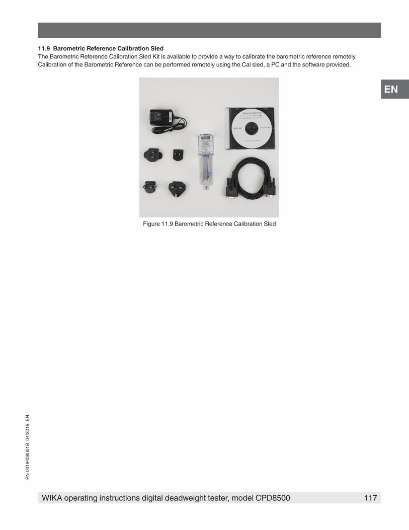
117WIKA operating instructions digital deadweight tester, model CPD8500
PN 0
0194
0800
1B 0
4/20
19 E
N
EN
11.9 Barometric Reference Calibration SledThe Barometric Reference Calibration Sled Kit is available to provide a way to calibrate the barometric reference remotely.Calibration of the Barometric Reference can be performed remotely using the Cal sled, a PC and the software provided.
Figure 11.9 Barometric Reference Calibration Sled

118 WIKA operating instructions digital deadweight tester, model CPD8500
PN 0
0194
0800
1B 0
4/20
19 E
N
EN
12. Appendix12.1 Measurement Units
Table 12.1 Measurement Units (unitno)
Code Description Output Format
1 pounds per square inch psi
2 inches of mercury @ 0°C in Hg 0°C
3 inches of mercury @ 60°F in Hg 60°F
4 inches of water @ 4°C in H2O 4°C
5 inches of water @ 20°C in H2O 20°C
6 inches of water @ 60°F in H2O 60°F
7 feet of water @ 4°C ft H2O 4°C
8 feet of water @ 20°C ft H2O 20°C
9 feet of water @ 60°F ft H2O 60°F
10 millitorr mTorr
11 inches of seawater @ 0°C 3.5% salinity in SW
12 feet of seawater @ 0°C 3.5% salinity ft SW
13 atmospheres atm14 bars bar15 millibars mbar16 millimeters of water @ 4°C mm H2O 4°C17 centimeters of water @ 4°C cm H2O 4°C18 meters of water @ 4°C m H2O 4°C19 millimeters of mercury @ 0°C mm Hg 0°C20 centimeters of mercury @ 0°C cm Hg 0°C21 torr Torr22 kilopascals kPa23 pascals Pa24 dyne per square centimeter dyn/cm225 grams per square centimeter g/cm226 kilograms per square centimeter kg/cm227 meters of seawater @ 0°C 3.5% salinity m SW28 ounce per square inch osi29 pounds per square foot pfs30 tons per square foot tsf31 percent of full scale % of Range32 micron of mercury @ 0°C mHg33 ton per square inch tsi34 meters of mercury @ 0°C MHg35 hectopascals hPa36 megapascals MPa37 millimeters of water @ 20°C mm H2O 20°C38 centimeter of water @ 20°C cm H2O 20°C39 meters of water @ 20°C m H2O 20°Cn/a User Units 1 User definedn/a User Units 2 User defined
12.2 Conversion Factors, PSI
12. Appendix
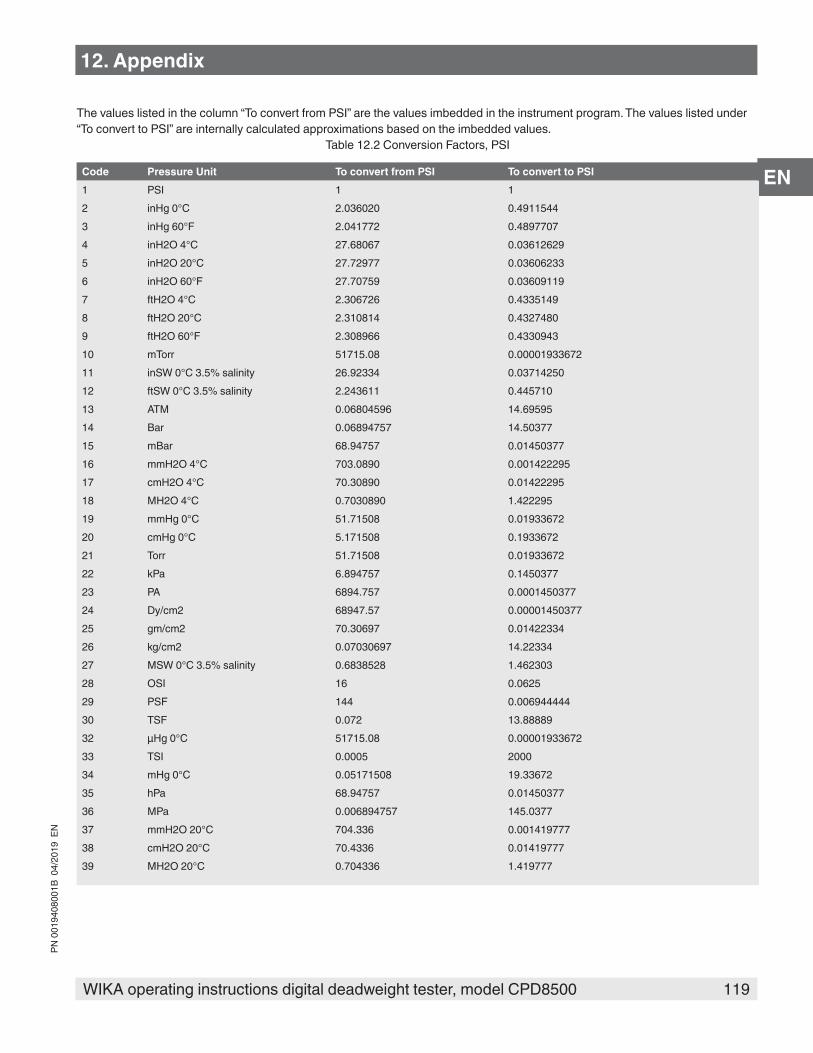
119WIKA operating instructions digital deadweight tester, model CPD8500
PN 0
0194
0800
1B 0
4/20
19 E
N
EN
The values listed in the column “To convert from PSI” are the values imbedded in the instrument program. The values listed under “To convert to PSI” are internally calculated approximations based on the imbedded values.
Table 12.2 Conversion Factors, PSI
Code Pressure Unit To convert from PSI To convert to PSI1 PSI 1 12 inHg 0°C 2.036020 0.49115443 inHg 60°F 2.041772 0.48977074 inH2O 4°C 27.68067 0.036126295 inH2O 20°C 27.72977 0.036062336 inH2O 60°F 27.70759 0.036091197 ftH2O 4°C 2.306726 0.43351498 ftH2O 20°C 2.310814 0.43274809 ftH2O 60°F 2.308966 0.433094310 mTorr 51715.08 0.0000193367211 inSW 0°C 3.5% salinity 26.92334 0.0371425012 ftSW 0°C 3.5% salinity 2.243611 0.44571013 ATM 0.06804596 14.6959514 Bar 0.06894757 14.5037715 mBar 68.94757 0.0145037716 mmH2O 4°C 703.0890 0.00142229517 cmH2O 4°C 70.30890 0.0142229518 MH2O 4°C 0.7030890 1.42229519 mmHg 0°C 51.71508 0.0193367220 cmHg 0°C 5.171508 0.193367221 Torr 51.71508 0.0193367222 kPa 6.894757 0.145037723 PA 6894.757 0.000145037724 Dy/cm2 68947.57 0.0000145037725 gm/cm2 70.30697 0.0142233426 kg/cm2 0.07030697 14.2233427 MSW 0°C 3.5% salinity 0.6838528 1.46230328 OSI 16 0.062529 PSF 144 0.00694444430 TSF 0.072 13.8888932 µHg 0°C 51715.08 0.0000193367233 TSI 0.0005 200034 mHg 0°C 0.05171508 19.3367235 hPa 68.94757 0.0145037736 MPa 0.006894757 145.037737 mmH2O 20°C 704.336 0.00141977738 cmH2O 20°C 70.4336 0.0141977739 MH2O 20°C 0.704336 1.419777
12. Appendix
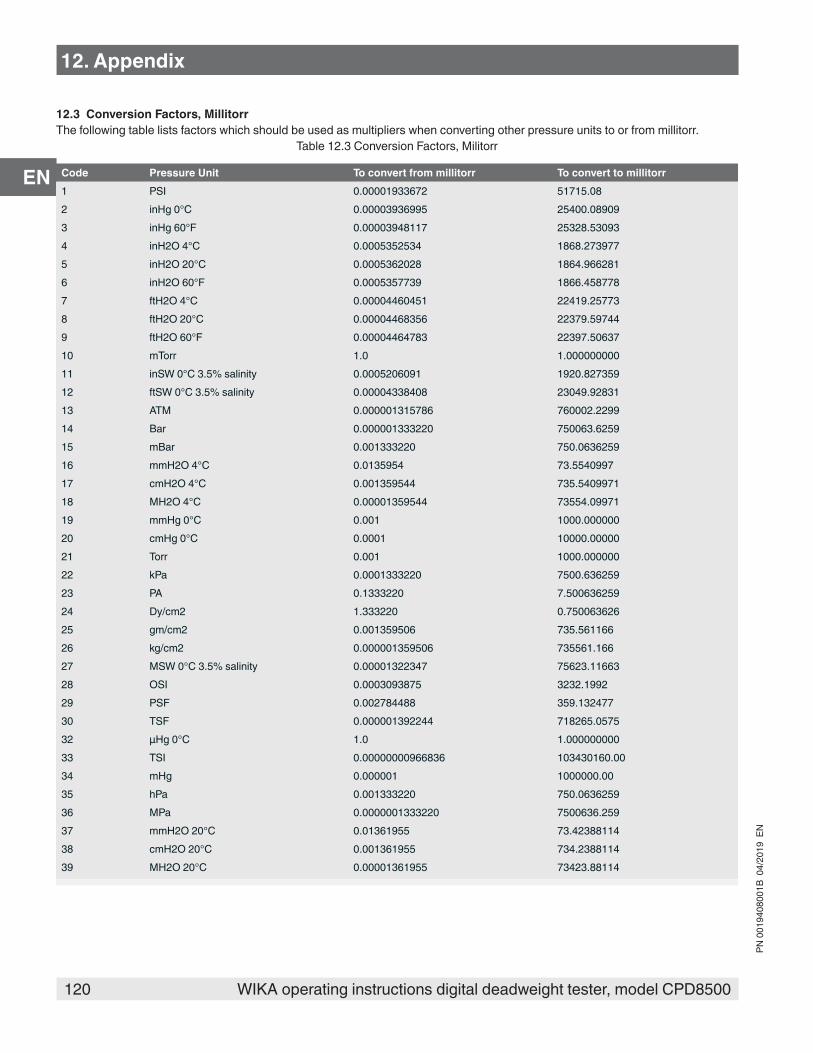
120 WIKA operating instructions digital deadweight tester, model CPD8500
PN 0
0194
0800
1B 0
4/20
19 E
N
EN
12.3 Conversion Factors, MillitorrThe following table lists factors which should be used as multipliers when converting other pressure units to or from millitorr.
Table 12.3 Conversion Factors, Militorr
Code Pressure Unit To convert from millitorr To convert to millitorr1 PSI 0.00001933672 51715.082 inHg 0°C 0.00003936995 25400.089093 inHg 60°F 0.00003948117 25328.530934 inH2O 4°C 0.0005352534 1868.2739775 inH2O 20°C 0.0005362028 1864.9662816 inH2O 60°F 0.0005357739 1866.4587787 ftH2O 4°C 0.00004460451 22419.257738 ftH2O 20°C 0.00004468356 22379.597449 ftH2O 60°F 0.00004464783 22397.5063710 mTorr 1.0 1.00000000011 inSW 0°C 3.5% salinity 0.0005206091 1920.82735912 ftSW 0°C 3.5% salinity 0.00004338408 23049.9283113 ATM 0.000001315786 760002.229914 Bar 0.000001333220 750063.625915 mBar 0.001333220 750.063625916 mmH2O 4°C 0.0135954 73.554099717 cmH2O 4°C 0.001359544 735.540997118 MH2O 4°C 0.00001359544 73554.0997119 mmHg 0°C 0.001 1000.00000020 cmHg 0°C 0.0001 10000.0000021 Torr 0.001 1000.00000022 kPa 0.0001333220 7500.63625923 PA 0.1333220 7.50063625924 Dy/cm2 1.333220 0.75006362625 gm/cm2 0.001359506 735.56116626 kg/cm2 0.000001359506 735561.16627 MSW 0°C 3.5% salinity 0.00001322347 75623.1166328 OSI 0.0003093875 3232.199229 PSF 0.002784488 359.13247730 TSF 0.000001392244 718265.057532 µHg 0°C 1.0 1.00000000033 TSI 0.00000000966836 103430160.0034 mHg 0.000001 1000000.0035 hPa 0.001333220 750.063625936 MPa 0.0000001333220 7500636.25937 mmH2O 20°C 0.01361955 73.4238811438 cmH2O 20°C 0.001361955 734.238811439 MH2O 20°C 0.00001361955 73423.88114
12. Appendix
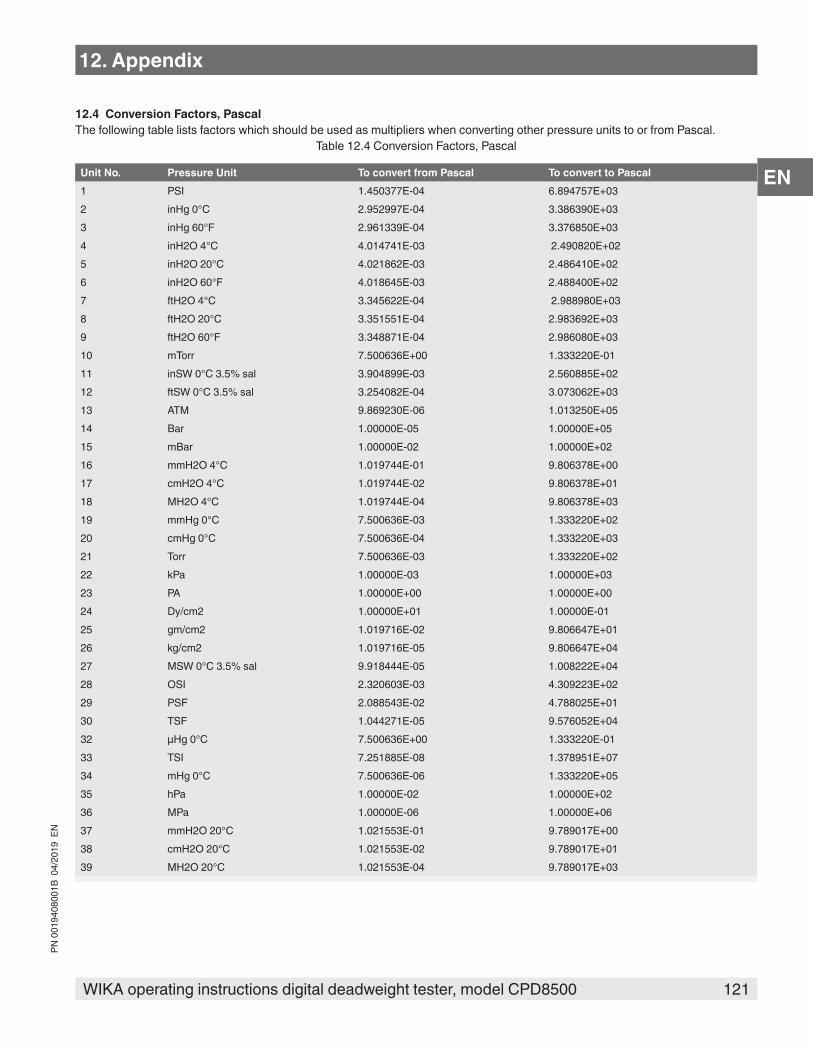
121WIKA operating instructions digital deadweight tester, model CPD8500
PN 0
0194
0800
1B 0
4/20
19 E
N
EN
12. Appendix
12.4 Conversion Factors, PascalThe following table lists factors which should be used as multipliers when converting other pressure units to or from Pascal.
Table 12.4 Conversion Factors, Pascal
Unit No. Pressure Unit To convert from Pascal To convert to Pascal1 PSI 1.450377E-04 6.894757E+032 inHg 0°C 2.952997E-04 3.386390E+033 inHg 60°F 2.961339E-04 3.376850E+034 inH2O 4°C 4.014741E-03 2.490820E+025 inH2O 20°C 4.021862E-03 2.486410E+026 inH2O 60°F 4.018645E-03 2.488400E+027 ftH2O 4°C 3.345622E-04 2.988980E+038 ftH2O 20°C 3.351551E-04 2.983692E+039 ftH2O 60°F 3.348871E-04 2.986080E+0310 mTorr 7.500636E+00 1.333220E-0111 inSW 0°C 3.5% sal 3.904899E-03 2.560885E+0212 ftSW 0°C 3.5% sal 3.254082E-04 3.073062E+0313 ATM 9.869230E-06 1.013250E+0514 Bar 1.00000E-05 1.00000E+0515 mBar 1.00000E-02 1.00000E+0216 mmH2O 4°C 1.019744E-01 9.806378E+0017 cmH2O 4°C 1.019744E-02 9.806378E+0118 MH2O 4°C 1.019744E-04 9.806378E+0319 mmHg 0°C 7.500636E-03 1.333220E+0220 cmHg 0°C 7.500636E-04 1.333220E+0321 Torr 7.500636E-03 1.333220E+0222 kPa 1.00000E-03 1.00000E+0323 PA 1.00000E+00 1.00000E+0024 Dy/cm2 1.00000E+01 1.00000E-0125 gm/cm2 1.019716E-02 9.806647E+0126 kg/cm2 1.019716E-05 9.806647E+0427 MSW 0°C 3.5% sal 9.918444E-05 1.008222E+0428 OSI 2.320603E-03 4.309223E+0229 PSF 2.088543E-02 4.788025E+0130 TSF 1.044271E-05 9.576052E+0432 µHg 0°C 7.500636E+00 1.333220E-0133 TSI 7.251885E-08 1.378951E+0734 mHg 0°C 7.500636E-06 1.333220E+0535 hPa 1.00000E-02 1.00000E+0236 MPa 1.00000E-06 1.00000E+0637 mmH2O 20°C 1.021553E-01 9.789017E+0038 cmH2O 20°C 1.021553E-02 9.789017E+0139 MH2O 20°C 1.021553E-04 9.789017E+03
122 WIKA operating instructions digital deadweight tester, model CPD8500
PN 0
0194
0800
1B 0
4/20
19 E
N
WIKA Alexander Wiegand SE & Co. KGAlexander-Wiegand-Straße 3063911 Klingenberg • GermanyTel. +49 9372 132-0Fax +49 9372 [email protected]
Mensor Corporation201 Barnes DriveSan Marcos, TX 78666 • USATel. (+1) 512 3964200-15Fax (+1) 512 3961820E-Mail [email protected]
WIKA subsidiaries worldwide can be found online at www.wika.com.