DIGITAL COMMUNICATIONS COURSE - … · DIGITAL COMMUNICATIONS COURSE ... FLDIGI DOWNLOAD INSTALL...
48
DIGITAL COMMUNICATIONS COURSE WASHINGTON DISTRICT 5 ARES PIERCE COUNTY TABLE OF CONTENTS / BOOKMARKS Click on the chapter and then the bookmark to go there directly. 1. OVERVIEW AND HISTORY OF DIGITAL COMMUNICATIONS 2. FLDIGI DOWNLOAD INSTALL AND OPERATE MT 63-2 K 3. WIRING AND SOUND CARD INTERFACES 4. CUT PASTE SAVE AND MESSAGE STORAGE 5. NTS AND ICS -213 FORMAT - USING FLMSG 6. MULTIPSK PACKET USING A SOUNDCARD 7. PACKET AND WINLINK 8. AIRMAIL PROGRAM - PACKET USING A TNC 9. Winmor RMS Express 10. DIGITAL COMMUNICATIONS - MESSAGE FORMS AND TECHNICS 11. EASYPAL DIGITAL IMAGE COMMUNICATIONS SOFTWARE GLOSSARY OF PACKET AND DIGITAL TERMS CHAPTER 1 OVERVIEW AND HISTORY OF DIGITAL COMMUNICATIONS What is a Digital Mode? Digital Modes are a means of operating Amateur radio from the computer keyboard. The computer acts as modem (modulator - demodulator), as well as allowing you to type, and see what the other person types. It can if desired also control the transmitter, change modes as required, and provides various convenient features such as easy tuning of signals and prearranged messages. Because of sophisticated digital signal processing which takes place inside the computer, digital modes can offer performance that cannot be achieved using voice (and in some cases even Morse), through reduced bandwidth, improved signal-to-noise performance and reduced transmitter power requirement. Some modes also offer built-in automatic error correction. Digital Mode operating procedure are not unlike Morse operation, and many of the same abbreviations are used. Internet email has become the globally accepted method for fast written communications for individuals, corporations, government agencies and other served organizations like the Red Cross and Salvation Army. Nevertheless, if a disaster strikes and a community's electrical power or telephone service is disrupted in any way, or the agencies email server goes down, then the Internet link is broken and normal email cannot flow. Digital communications have been around for along time. Many consider CW or Morse Code to be the original radio digital mode of communications. But many other forms of visual and audio communications existed prior to Morse. Indian smoke signals, semaphore flags, drums and bugles to name just a few. Samual Morse sends the first message Army code operators
Transcript of DIGITAL COMMUNICATIONS COURSE - … · DIGITAL COMMUNICATIONS COURSE ... FLDIGI DOWNLOAD INSTALL...

DIGITAL COMMUNICATIONS COURSEWASHINGTON DISTRICT 5 ARES
PIERCE COUNTY
TABLE OF CONTENTS / BOOKMARKSClick on the chapter and then the bookmark to go there directly.1. OVERVIEW AND HISTORY OF DIGITAL COMMUNICATIONS2. FLDIGI DOWNLOAD INSTALL AND OPERATE MT63-2K3. WIRING AND SOUND CARD INTERFACES4. CUT PASTE SAVE AND MESSAGE STORAGE5. NTS AND ICS-213 FORMAT - USING FLMSG 6. MULTIPSK PACKET USING A SOUNDCARD7. PACKET AND WINLINK8. AIRMAIL PROGRAM - PACKET USING A TNC9. Winmor RMS Express10. DIGITAL COMMUNICATIONS - MESSAGE FORMS AND TECHNICS11. EASYPAL DIGITAL IMAGE COMMUNICATIONS SOFTWAREGLOSSARY OF PACKET AND DIGITAL TERMS CHAPTER 1 OVERVIEW AND HISTORY OF DIGITAL COMMUNICATIONS
What is a Digital Mode?Digital Modes are a means of operating Amateur radio from the computer keyboard. The computer acts as modem (modulator - demodulator), as well as allowing you to type, and see what the other person types. It can if desired also control the transmitter, change modes as required, and provides various convenient features such as easy tuning of signals and prearranged messages. Because of sophisticated digital signal processing which takes place inside the computer, digital modes can offer performance that cannot be achieved using voice (and in some cases even Morse), through reduced bandwidth, improved signal-to-noise performance and reduced transmitter power requirement. Some modes also offer built-in automatic error correction. Digital Mode operating procedure are not unlike Morse operation, and many of the same abbreviations are used. Internet email has become the globally accepted method for fast written communications for individuals, corporations, government agencies and other served organizations like the Red Cross and Salvation Army. Nevertheless, if a disaster strikes and a community's electrical power or telephone service is disrupted in any way, or the agencies email server goes down, then the Internet link is broken and normal email cannot flow. Digital communications have been around for along time. Many consider CW or Morse Code to be the original radio digital mode of communications. But many other forms of visual and audio communications existed prior to Morse. Indian smoke signals, semaphore flags, drums and bugles to name just a few. Samual Morse sends the first message Army code operators
A Marconi Station operator What hath God Wrought? These famous words were telegraphed by Samuel F. B. Morse in 1844, although the patent for the "electric telegraph" was submitted in 1837 by Charles Wheatstone. By the time of the Civil War, telegraph communications spanned the United States, and in 1866, the first trans-Atlantic cable was laid between the US and France. In 1875, a Frenchman named Emile Baudot developed a code suitable for machine encoding and decoding. But the nesessary equipment to utilize that code wasn’t ready yet. That didn’t happen until the invention of the Teletypwriter in the early 1900’s which used his code. Widescale use of the mechanical teleprinter lasted for over 50 years! In 1846, Alexander Bain used punched tape to send telegrams. Paper punch tape was used in many applications from textile weaving looms, programing CNC machine tools, received API news services tape rerun to set type for newspaper presses and of course to load programing into early computers into the 1970’s.
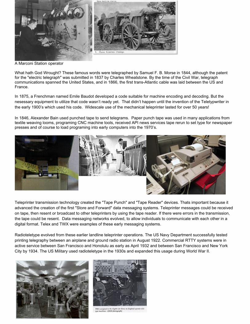
Teleprinter transmission technology created the "Tape Punch" and "Tape Reader" devices. Thats important because it advanced the creation of the first "Store and Forward" data messaging systems. Teleprinter messages could be received on tape, then resent or broadcast to other teleprinters by using the tape reader. If there were errors in the transmission, the tape could be resent. Data messaging networks evolved, to allow individuals to communicate with each other in a digital format. Telex and TWX were examples of these early messaging systems. Radioteletype evolved from these earlier landline teleprinter operations. The US Navy Department successfully tested printing telegraphy between an airplane and ground radio station in August 1922. Commercial RTTY systems were in active service between San Francisco and Honolulu as early as April 1932 and between San Francisco and New York City by 1934. The US Military used radioteletype in the 1930s and expanded this usage during World War II.
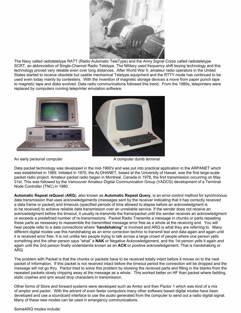
The Navy called radioteletype RATT (Radio Automatic TeleType) and the Army Signal Corps called radioteletype SCRT, an abbreviation of Single-Channel Radio Teletype. The Military used frequency shift keying technology and this technology proved very reliable even over long distances. After World War II, amateur radio operators in the United States started to receive obsolete but usable mechanical Teletype equipment and the RTTY mode has continued to be used even today mainly by contesters. With the invention of magnetic storage devices a move from paper punch tape to magnetic tape and disks evolved. Data radio communications followed this trend. From the 1980s, teleprinters were replaced by computers running teleprinter emulation software.
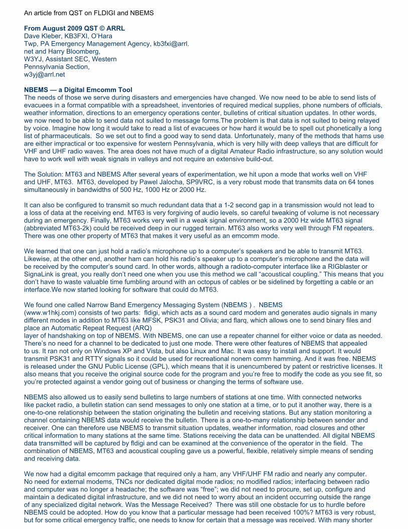
An early personal computer A computer dumb terminal Data packet technology was developed in the mid-1960's and was put into practical application in the ARPANET which was established in 1969. Initiated in 1970, the ALOHANET, based at the University of Hawaii, was the first large-scale packet radio project. Amateur packet radio began in Montreal, Canada in 1978, the first transmission occurring on May 31st. This was followed by the Vancouver Amateur Digital Communication Group (VADCG) development of a Terminal Node Controller (TNC) in 1980. Automatic Repeat reQuest (ARQ), also known as Automatic Repeat Query, is an error-control method for synchronous data transmission that uses acknowledgements (messages sent by the receiver indicating that it has correctly received a data frame or packet) and timeouts (specified periods of time allowed to elapse before an acknowledgment is to be received) to achieve reliable data transmission over an unreliable service. If the sender does not receive an acknowledgment before the timeout, it usually re-transmits the frame/packet until the sender receives an acknowledgment or exceeds a predefined number of re-transmissions. Packet Radio Transmits a message in chunks or parts repeating these parts as nessesary to reassemble the transmitted message error free as a whole at the receiving end. You will hear people refer to a data connections where “handshaking” is involved and ARQ is what they are referring to. Many different digital modes use this handshaking as an error correction technic to transmit text and data again and again until it is received error free. It is not unlike two people trying to talk across a large crowd of people where one person yells something and the other person says “what” a NAK or Negative Acknowledgement, and the 1st person yells it again and again until the 2nd person finally understands known as an ACK or positive acknowledgement. That is handshaking or ARQ. The problem with Packet is that the chunks or packets have to be received totally intact before it moves on to the next packet of information. If this packet is not received intact before the timeout period the connection will be dropped and the message will not go thru. Pactor tried to solve this problem by storeing the recieved parts and filling in the blanks from the repeated packets slowly chipping away at the message as a whole. This worked better on HF than packet where fadding, static crashes and qrm would drop characters in transmission. Other forms of Store and forward systems were developed such as Amtor and then Pactor 1 which was kind of a mix of amptor and pactor. With the advent of even faster computors many other software based digital modes have been developed and use a soundcard interface to use the audio generated from the computer to send out a radio digital signal. Many of these new modes can be used in emergency communications. SomeARQ modes include:

Packet, Amptor, Pactor Gtor and Clover. (FEC) or Forward Error Correction is any number of error correction scheme’s that do not use a connection or ARQ handshaking between stations. They are reffered to as broadcast modes because the transmitting stations stays in transmit through the whole transmission of the message. Error correction is accomplised by incorporating redundancies within the transmission such as broadcasting each character three times and assembling any two that are the same. This is just one sort of error correction technic and there are many. But it all takes place in one asychronous transmission of the whole message or messages. Some FEC modes includePSK, MFSK MT63 RTTY ASCII OLIVIA AND DOMINO. The use of an Amateur Radio digital communications network linked to the Internet can become an effective and important tool in keeping an ARES group and its served agencies connected globally without the normal wired Internet connection. It allows an Amateur station to assist served agencies and keep them connected from inside a disaster area, and without normal email servers or Internet links or telephones. Pierce County ARES can use many forms of communications to transmit messages during times of disaster and/or emergencies. And in order to accomplish our objectives we need to have redundancy and utilize many modes and systems, Digital communications with Winlink and Point to point systems like NBEMS have the ability of providing error-free messages to a destination, minimizing public disclosure of sensitive information, and in a written format.
Effective network communications require a mix of voice and digital text transmissions. Digital communications will never replace voice communications. Nets and training for voice operations are just as important as it ever was. Voice is quicker for command and control functions. But for long lists of numbers and text it can't come close to doing the job. Also voice messages must be re-transcribed for record keeping and to re-inject it into a computer network being used by an EOC. So written formal message traffic is preferred by EOC's and other government and disaster support agencies. A great digital system to use for ARES/RACES Emcomm is the Narrow Band Emergency Messaging System or NBEMS. NBEMS utilizes a suite of software programs including FLDIGI to send and receive large amounts of data in a short time. The FLDIGI program is the basis of our digital communications. Each and every member that has a laptop preferably, but any computer should have FLDIGI installed on it. With this program digital traffic can be exchanged even without a sound card interface or TNC. This most basic method of communication is called acoustic coupling. Meaning there is no wired interface between the computer and the transceiver. This acoustic coupling can mean that a station with limited resources i.e. just a laptop and VHF transceiver can still be capable of moving large amounts of message traffic. This by no means is the best way to do it, but will work just fine if that's all you have. To receive messages all that is needed is a computer mic placed next to your transceivers speaker. FLDIGI will decode the audio message being sent. To transmit only requires that you place your transceivers mic near the computer speaker and depress the push to talk switch while the audio is being sent out. This is the most basic setup. Other stations can relay these messages into the packet and winlink system. This is why every ARES station needs this program and basic setup. Even if you have more advanced modes like Packet, Pactor and Winmor and connect to the Winlink system you still need to copy traffic from these most basic stations and relay to Winlink for them. A better method than acoustic coupling is to acquire a wired sound card interface between the computer and the transceiver. This will allow the computer to control the PTT (push to talk} and allow other more advanced ARQ type modes like packet and Winmor to be used that can access the Winlink network to the Internet. below are some web sites where these programs can be found and downloaded:

FLDIGI, FLMSG and FLARQ NBEMS suite of emergency communications software. http://www.w1hkj.com/Fldigi.htmlAIRMAIL Packet and Pactor software to be used with a TNC. http://www.airmail2000.com/MultiPSK for Packet using a soundcard interface. http://f6cte.free.fr/index_anglais.htmWinmor RMS Express for HF using a soundcard interface. http://www.winlink.org/WINMOR Chapter 1 Summary
● Understand the basic History of Digital communications.● Understand the need for digital communications as opposed to voice communications● Understand the term Packet Radio and how it transmits error free data.● Understand ARQ synchronous data transmission● Understand FEC asychronous data transmission● Understand that MT63-2k mode, Packet, Pactor and Winmor are the digital modes used most in Pierce County
ARES.● Understand the term Acoustic coupling and when and how it is used. Understand the importance of other stations
being able to receive MT63-2k and relay it on to Winlink for those stations that cannot connect directly to Winlink.● Be aware of the importantance of the Winlink Network and the routing of traffic through it.

CHAPTER 2 FLDIGI DOWNLOAD INSTALL AND OPERATE MT63-2KFlDIGI is the basic software we use for digital communications. Download it at this address: FLDIGI, FLMSG and FLARQ NBEMS suite of emergency communications software. http://www.w1hkj.com/Fldigi.html All of the Help files on FLDIGI are available online at: http://www.w1hkj.com/FldigiHelp-3.21/index.html It is simple, free and very easy to use. Message text can be cut and pasted from both the transmit and recieve windows making relay of messages and transfer of text from windows notpad easy. The most basic mode of preference in FLDIGI on VHF and UHF is MT63-2k. Fldigi is a computer program intended for Amateur Radio Digital Modes operation using a PC (Personal Computer). Fldigi operates (as does most similar software) in conjunction with a conventional VHF/UHF FM or HF SSB radio transceiver, and uses the PC sound card as the main means of input from the radio and output to the radio. These are audio-frequency signals. The software also controls the radio by means of another connection, typically a serial port or USB port but VOX or (voice on contact) can also be used to control push to talk. Fldigi is multi-mode, which means that it is able to operate many popular digital modes without switching programs. Fldigi includes all the popular modes, such as DominoEX, MFSK16, PSK31, and RTTY. Unusually, Fldigi is available for multiple computer operating systems; FreeBSD™; Linux™, OS X™ and Windows™. For local portable, mobile and fixed station operations on 2m and 70cm FM (repeater or simplex), MT63 2K long interleave is our basic mode for detailed situation reports and database transmission and has been chosen for the following reasons:- Can be used very effectively without a sound card interface (audio coupling)- Extremely effective under poor RF conditions- Extremely accurate decoding (major duplication of data and forward error corrected)- Fairly forgiving on audio levels (lighter vs hot on audio levels are always better on both tx and rx)- Excellent for sending larger situation reports or databases- Transmission speed is about 200wpm in the 2000Hz version.- As found in FLDIGI the frequency is set and bracketed so if the user tunes his transciever to the right frequency he will not have to adjust frequency in the water fall display window like many other digital modes making this mode more reliable.
An article from QST on FLDIGI and NBEMS From August 2009 QST © ARRLDave Kleber, KB3FXI, O’Hara Twp, PA Emergency Management Agency, [email protected] and Harry Bloomberg, W3YJ, Assistant SEC, Western Pennsylvania Section,[email protected] NBEMS — a Digital Emcomm ToolThe needs of those we serve during disasters and emergencies have changed. We now need to be able to send lists of evacuees in a format compatible with a spreadsheet, inventories of required medical supplies, phone numbers of officials, weather information, directions to an emergency operations center, bulletins of critical situation updates. In other words, we now need to be able to send data not suited to message forms.The problem is that data is not suited to being relayed by voice. Imagine how long it would take to read a list of evacuees or how hard it would be to spell out phonetically a long list of pharmaceuticals. So we set out to find a good way to send data. Unfortunately, many of the methods that hams use are either impractical or too expensive for western Pennsylvania, which is very hilly with deep valleys that are difficult for VHF and UHF radio waves. The area does not have much of a digital Amateur Radio infrastructure, so any solution would have to work well with weak signals in valleys and not require an extensive build-out. The Solution: MT63 and NBEMS After several years of experimentation, we hit upon a mode that works well on VHF and UHF, MT63. MT63, developed by Pawel Jalocha, SP9VRC, is a very robust mode that transmits data on 64 tones simultaneously in bandwidths of 500 Hz, 1000 Hz or 2000 Hz. It can also be configured to transmit so much redundant data that a 1-2 second gap in a transmission would not lead to a loss of data at the receiving end. MT63 is very forgiving of audio levels, so careful tweaking of volume is not necessary during an emergency. Finally, MT63 works very well in a weak signal environment, so a 2000 Hz wide MT63 signal (abbreviated MT63-2k) could be received deep in our rugged terrain. MT63 also works very well through FM repeaters. There was one other property of MT63 that makes it very useful as an emcomm mode. We learned that one can just hold a radio’s microphone up to a computer’s speakers and be able to transmit MT63. Likewise, at the other end, another ham can hold his radio’s speaker up to a computer’s microphone and the data will be received by the computer’s sound card. In other words, although a radioto-computer interface like a RIGblaster or SignaLink is great, you really don’t need one when you use this method we call “acoustical coupling.” This means that you don’t have to waste valuable time fumbling around with an octopus of cables or be sidelined by forgetting a cable or an interface.We now started looking for software that could do MT63. We found one called Narrow Band Emergency Messaging System (NBEMS ) . NBEMS (www.w1hkj.com) consists of two parts: fldigi, which acts as a sound card modem and generates audio signals in many different modes in addition to MT63 like MFSK, PSK31 and Olivia; and flarq, which allows one to send binary files and place an Automatic Repeat Request (ARQ) layer of handshaking on top of NBEMS. With NBEMS, one can use a repeater channel for either voice or data as needed. There’s no need for a channel to be dedicated to just one mode. There were other features of NBEMS that appealed to us. It ran not only on Windows XP and Vista, but also Linux and Mac. It was easy to install and support. It would transmit PSK31 and RTTY signals so it could be used for recreational nonem comm hamming. And it was free. NBEMS is released under the GNU Public License (GPL), which means that it is unencumbered by patent or restrictive licenses. It also means that you receive the original source code for the program and you’re free to modify the code as you see fit, so you’re protected against a vendor going out of business or changing the terms of software use. NBEMS also allowed us to easily send bulletins to large numbers of stations at one time. With connected networks like packet radio, a bulletin station can send messages to only one station at a time, or to put it another way, there is a one-to-one relationship between the station originating the bulletin and receiving stations. But any station monitoring a channel containing NBEMS data would receive the bulletin. There is a one-to-many relationship between sender and receiver. One can therefore use NBEMS to transmit situation updates, weather information, road closures and other critical information to many stations at the same time. Stations receiving the data can be unattended. All digital NBEMS data transmitted will be captured by fldigi and can be examined at the convenience of the operator in the field. The combination of NBEMS, MT63 and acoustical coupling gave us a powerful, flexible, relatively simple means of sending and receiving data. We now had a digital emcomm package that required only a ham, any VHF/UHF FM radio and nearly any computer. No need for external modems, TNCs nor dedicated digital mode radios; no modified radios; interfacing between radio and computer was no longer a headache; the software was “free”; we did not need to procure, set up, configure and maintain a dedicated digital infrastructure, and we did not need to worry about an incident occurring outside the range of any specialized digital network. Was the Message Received? There was still one obstacle for us to hurdle before NBEMS could be adopted. How do you know that a particular message had been received 100%? MT63 is very robust, but for some critical emergency traffic, one needs to know for certain that a message was received. With many shorter

text messages, a ham can just “eyeball” the message and see that something’s amiss. But how can one determine that data exported from a spreadsheet, was received intact? The flarq program can do this, but only at a cost of significant overhead. We proposed a solution to the problem to the NBEMS developers. How about embedding a checksum in the data sent by fldigi that could be used by the receiving station to determine if the message had been received intact? A checksum is the result of a calculation involving all of the data in the message. If the receiving station computed the same checksum in the message as the sending station, the message had been received 100%. This is not as elegant a solution as flarq, but it was more efficient and simpler to implement. After some discussion, the developers went to work and in a very short period of time came up with a solution, a program called Wrap. Wrap would envelop a message with special strings to indicate the start and end of “wrapped” data. Within this wrapped message would be stored a checksum and the name of a file. This wrapped message would then be sent using fldigi. At the receiving end, fldigi would look for the start and end of the wrapped data. Once a wrapped message had been identified, fldigi would extract it and store it in a folder. The operator would then run Wrap against this file to compute a checksum on the received data and to compare it to the checksum that the sending station had embedded in the message. If the two checksums were equal, the receiving operator would see a message indicating success and the original message would be extracted. Training We then started an effort to recruit and train operators in using NBEMS. Dave organized an informal group named wpaNBEMS www.wpanbems.org). This group holds training nets on repeaters using Olivia and MT63. Harry volunteered as an Assistant Section Emergency Coordinator and wrote a western Pennsylvania digital emcomm standards document and helped train RES® groups. One recent training net illustrated the portability of the NBEMS software and the fact that it does not require very powerful or expensive hardware. We were able to successfully send and receive MT63 data between machines running Windows Vista, Windows XP, Macintosh OS X and Ubuntu Linux. Several of our net members use Dell Mini 9s for NBEMS, running both Linux and Windows XP, and find that they work very well as a cheap digital emcomm workstation. Applying Lessons Learned Dave and Harry participated in the 2008 Simulated Emergency Test. Harry was assigned to a parking lot of UPMC St Margaret Hospital in Pittsburgh. Dave was located at a simulated EOC at Skyview Radio Society’s clubhouse approximately 10 miles away.Harry was asked to use NBEMS to send a text file exported from a spreadsheet. This spreadsheet contained the names of 25 patients sent to the hospital, and for each patient, a nine digit ID number, a phone number and a postal address. Just as Harry was about to begin transmitting the data, the repeater that had been chosen for the data transmission failed. No big deal. Harry and Dave met on a backup repeater and the data file was successfully transmitted in just under 2 minutes. The harsh lesson that Ivan taught us had been learned. From August 2009 QST © ARRL Setting Up 2.1. Fldigi settingsEssentialsUse the menu Configure->Operator item to set the operator name, callsign, locator and so on. If you have more than one sound card, use the menu Configure->Sound Card, Audio Devices tab, to select the sound card you wish to use. You can ignore the other tabs for now. Rig Control (Not requied in ARES... but push to talk control is required)Use the menu Configure->Rig Control item to set how you will control the rig. If you will key the rig via a serial port, in the Hardware PTT tab select Use serial port PTT, the device name you will use, and which line controls PTT. If in doubt, check both RTS and DTR. You must then press the Initialize button. If you plan to use CAT control of the rig via the COM port, check Use Hamlib in the Hamlib tab. Select your rig model from the drop-down menu and set the serial port device name, baud rate, and RTS/CTS options as needed. If in addition you wish to use PTT control via CAT, also check PTT via Hamlib command. You must then press the Initialize button.
If your rig is CAT-capable but not yet supported by Hamlib, it may still be possible to control it via Fldigi's RigCAT system. Refer to the Online Documentation for details. CPU SpeedWhen you start Fldigi for the very first time, it makes a series of measurements to determine your computer's processing speed. Although these measurements are usually accurate, if you have a very slow processor (under 700MHz), you should verify that Slow CPU under Configure->Misc->CPU has been enabled. The receiver decoding strategy of certain modems uses fewer processor cycles in this mode. ModemsEach of the modems can be individually set up from the Configure->Modems multi-tabbed dialog. You need not change

anything here to start with, although it might be a good idea to set the secondary text for DominoEX and THOR to something useful, such as your call and locator. [Secondary text is transmitted when the text you type does not keep up with the typing speed of the mode — this handy text appears in a small window at the very bottom of the screen.]Note that this set of tabs is also where you set the RTTY modem speed and shift, although the default values should be fine for normal operation.
Other settingsUse the menu Configure->UI, Restart tab, to set the aspect ratio of the waterfall display and whether or not you want to dock a second digiscope to the main window. Use the menu Configure->IDs item to set whether you wish to transmit RSID data at the start of each over (this is for the benefit of others and does not affect RSID reception). If you plan to regularly use the RSID feature on receive, you should deselect the option that starts new modems at the “sweet spot” frequencies in Misc->Sweet Spot. Finally, use the menu item Configure->Save Config to save the new configuration. Sound Card MixerUse your sound card Master Volume applet to select the sound card, the Wave output and set the transmit audio level. You can check the level using the Tune button, top right, beyond the Menu. On Windows, the Volume applet can usually be opened by clicking Start->Run… and entering sndvol32, or from the Control Panel. Use your sound card Recording Control applet to select the sound card, the Line or Mic input and set the receiver audio level. Watch the waterfall display for receiver noise when setting the level. If you see any dark blue noise, you have the right input and about the right level. The actual setting is not very important, provided you see blue noise. If the audio level is too high, the little diamond shaped indicator (bottom right) will show red. The waterfall may also show red bands. Performance will be degraded if the level is too high. On Windows, the Record applet can usually be opened by clicking Start->Run… and entering sndvol32, or from the Control Panel. If opened from the Control Panel, you'll end up with the Master Volume applet, and need to switch using Options->Properties, and selecting the Recording radio button. Guided TourThe main window consists of three main panes. Study it carefully as you read these notes. From top to bottom, these are the Receive pane (navajo white), the Transmit pane (light cyan), and the Waterfall pane (black). At the top is the collection of entry items which form the Log Data, and at the very top, a conventional drop-down Menu system, with entries for File, Op Mode, Configure, View and Help. Between the Transmit and the Waterfall panes is a line of boxes (buttons) which represent the Function Keys F1 - F12. This is the Macro group. Below the Waterfall pane is another line of boxes (buttons), which provide various control features. This is the Controls group. The program and various buttons can mostly be operated using the mouse or the keyboard, and users generally find it convenient to use the mouse while tuning around, and the keyboard and function keys during a QSO. Receive PaneThis is where the text from decoded incoming signals is displayed, in black text. When you transmit, the transmitted text is also displayed here, but in red, so the Receive pane becomes a complete record of the QSO. The information in this pane can also be logged to a file. The line at the bottom of this pane can be dragged up and down with the mouse. You might prefer to drag it down a bit to enlarge the Receive pane and reduce the size of the Transmit pane. Transmit PaneThis is where you type what you want to transmit. The mouse must click in here before you type (to obtain focus) otherwise your text will go nowhere. You can type in here while you are receiving, and when you start transmitting, the text already typed will be sent first. This trick is a cool way to impress others with your typing speed! As the text is transmitted, the text colour changes from black to red. At the end of the over, all the transmitted text (and any as yet not transmitted) will be deleted. Waterfall PaneThis is the main tuning facility. There are three modes, Waterfall, FFT and Signal, selected by a button in the Control group. For now, leave it in Waterfall mode, as this is the easiest to tune with, and gives the best identification of the signal. WF (Waterfall)A spectrogram display of signal strength versus frequency over passing time. The receiver passband is analysed and displayed with lower frequencies to the left, higher to the right. Weak signals and background noise are dark while stronger signals show as brighter colours. As time passes (over a few seconds), the historic signals move downwards like a waterfall. FFT (Fast Fourier Transform)A spectrum display of the mean signal strength versus frequency. Again frequency is displayed from left to right, but now the vertical direction shows signal strength and there is no brightness or historic information.

SIG (Signal)An oscilloscope type of display showing the raw audio being captured by the sound card. At the top of the pane is a scale of frequency in Hz, which corresponds to the frequency displayed immediately below it. This scale can be moved around and zoomed using buttons in the Control group. As you move the mouse around in this pane you will see a yellow group of tuning marks following the mouse pointer. Tuning is achieved by left-clicking on a signal displayed by the waterfall in this pane. Use these yellow marks to exactly straddle the signal and then left-click on the centre of the signal. The tuning marks change to red. The red vertical lines will show the approximate width of the active signal area (the expected signal bandwidth), while a red horizontal bar above will indicate the receiver software's active decoding range. When you left-click, the red marks move to where you clicked, and will attempt to auto-track the signal from there.
Audio history and “casual tuning”You can temporarily “monitor” a different signal by right-clicking on it. As long as you hold the mouse button down, the signal under it will be decoded; as soon as you release the mouse, decoding will revert to the previously tuned spot (where the red marks are). If you also hold the Control key down before right-clicking, Fldigi will first decode all of its buffered audio at that frequency. MenuAt the very top of the program window is a conventional drop-down menu. If you click on any of the items, a list of optional functions will appear. Keyboard menu selection is also provided. Where underscored characters are shown in the menu, you can select these menu items from the keyboard using the marked character and Alt at the same time, then moving around with the up/down/left/right keys. Press Esc to quit from the menu with no change.

Menu functions FileAllows you to open or save Macros (we won't get into that here), turn on/off logging to file, record/play audio samples, and exit the program. You can also exit the program by clicking on the X in the top right corner of the window, in the usual manner. Op ModeThis is where you select the operating modem used for transmission and reception. Some modes only have one option. Where more are offered, drag the mouse down the list and sideways following the arrow to a secondary list, before releasing it. When you start the program next time, it will remember the last mode you used. In Pierce county ARES we use MT63-2000Hz long interleave mode but there are many other modes of operation that can be used in amateur radio. In amateur operations not all the modes are widely used, so choose a mode which (a) maximises your chance of a QSO, and (b) is appropriate for the band, conditions, bandwidth requirements and permissions relevant to your operating licence. At the bottom of the list are two “modes” which aren't modes at all, and do not transmit (see Online Documentation for details). WWV mode allows you to receive a standard time signal so the beeps it transmits can be used for sound card calibration. Freq Analysis provides just a waterfall display with a very narrow cursor, and a frequency meter which indicates the received frequency in Hz to two decimal places. This is useful for on-air frequency measurement. ConfigureThis is where you set up the program to suit your computer, yourself and your operating preferences. The operating settings of the program are grouped into several categories and there are menu items in which you enter your personal information, or define your computer sound card, for example. Modems can be individually changed, each having different adjustments. The Modems dialog has multiple tabs, so you can edit any one of them. Don't fool with the settings until you know what you are doing! The final item, Save Config allows you to save the altered configuration for next time you start the program (otherwise changes are temporary). ViewThis menu item allows you to open extra windows. Most will be greyed out, but two that are available are the Digiscope, and the PSK Browser. The Digiscope provides a mode-specific graphical analysis of the received signal, and can have more than one view (left click in the new window to change the view), or maybe none at all. The PSK Browser is a rather cool tool that allows you to monitor several PSK31 signals all at the same time! These windows can be resized to suit. HelpBrings up the Online Documentation, the Fldigi Home Page, and various information about the program. Other controlsRSIDThis button turns on the receive RSID (automatic mode detection and tuning) feature. When in use, the button turns yellow and no text reception is possible until a signal is identified, or the feature is turned off again. If you plan to use the RSID feature on receive, you must leave the Start New Modem at Sweet Spot item in the menu Configure->Defaults->Misc tab unchecked.
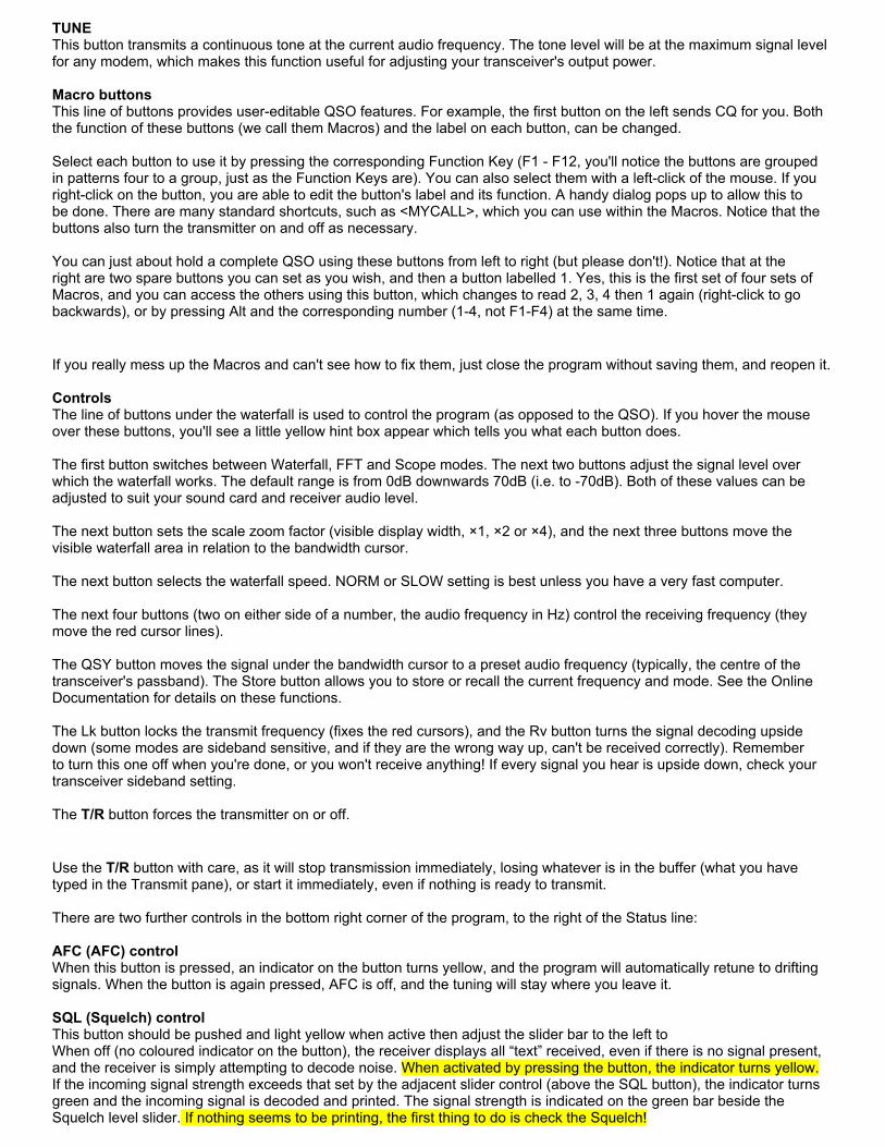
TUNEThis button transmits a continuous tone at the current audio frequency. The tone level will be at the maximum signal level for any modem, which makes this function useful for adjusting your transceiver's output power. Macro buttonsThis line of buttons provides user-editable QSO features. For example, the first button on the left sends CQ for you. Both the function of these buttons (we call them Macros) and the label on each button, can be changed. Select each button to use it by pressing the corresponding Function Key (F1 - F12, you'll notice the buttons are grouped in patterns four to a group, just as the Function Keys are). You can also select them with a left-click of the mouse. If you right-click on the button, you are able to edit the button's label and its function. A handy dialog pops up to allow this to be done. There are many standard shortcuts, such as <MYCALL>, which you can use within the Macros. Notice that the buttons also turn the transmitter on and off as necessary. You can just about hold a complete QSO using these buttons from left to right (but please don't!). Notice that at the right are two spare buttons you can set as you wish, and then a button labelled 1. Yes, this is the first set of four sets of Macros, and you can access the others using this button, which changes to read 2, 3, 4 then 1 again (right-click to go backwards), or by pressing Alt and the corresponding number (1-4, not F1-F4) at the same time.
If you really mess up the Macros and can't see how to fix them, just close the program without saving them, and reopen it. ControlsThe line of buttons under the waterfall is used to control the program (as opposed to the QSO). If you hover the mouse over these buttons, you'll see a little yellow hint box appear which tells you what each button does. The first button switches between Waterfall, FFT and Scope modes. The next two buttons adjust the signal level over which the waterfall works. The default range is from 0dB downwards 70dB (i.e. to -70dB). Both of these values can be adjusted to suit your sound card and receiver audio level. The next button sets the scale zoom factor (visible display width, ×1, ×2 or ×4), and the next three buttons move the visible waterfall area in relation to the bandwidth cursor. The next button selects the waterfall speed. NORM or SLOW setting is best unless you have a very fast computer. The next four buttons (two on either side of a number, the audio frequency in Hz) control the receiving frequency (they move the red cursor lines). The QSY button moves the signal under the bandwidth cursor to a preset audio frequency (typically, the centre of the transceiver's passband). The Store button allows you to store or recall the current frequency and mode. See the Online Documentation for details on these functions. The Lk button locks the transmit frequency (fixes the red cursors), and the Rv button turns the signal decoding upside down (some modes are sideband sensitive, and if they are the wrong way up, can't be received correctly). Remember to turn this one off when you're done, or you won't receive anything! If every signal you hear is upside down, check your transceiver sideband setting. The T/R button forces the transmitter on or off.
Use the T/R button with care, as it will stop transmission immediately, losing whatever is in the buffer (what you have typed in the Transmit pane), or start it immediately, even if nothing is ready to transmit. There are two further controls in the bottom right corner of the program, to the right of the Status line: AFC (AFC) controlWhen this button is pressed, an indicator on the button turns yellow, and the program will automatically retune to drifting signals. When the button is again pressed, AFC is off, and the tuning will stay where you leave it. SQL (Squelch) controlThis button should be pushed and light yellow when active then adjust the slider bar to the left toWhen off (no coloured indicator on the button), the receiver displays all “text” received, even if there is no signal present, and the receiver is simply attempting to decode noise. When activated by pressing the button, the indicator turns yellow. If the incoming signal strength exceeds that set by the adjacent slider control (above the SQL button), the indicator turns green and the incoming signal is decoded and printed. The signal strength is indicated on the green bar beside the Squelch level slider. If nothing seems to be printing, the first thing to do is check the Squelch!

Status LineAt the very bottom line of the Fldigi window is a row of useful information. At the left is the current operating mode. Next (some modes) is the measured signal-to-noise ratio at the receiver, and (in some modes) the measured signal intermodulation level (IMD). The larger central box shows (in DominoEX and THOR modes) the received Secondary Text. This is information (such as station identification) which is transmitted automatically whenever the transmitter has completed all user text that is available to send. It is transmitted using special characters, and is automatically directed to this special window. Secondary text you transmit is also shown here. This box changes size when you enlarge the program window. Operating ProcedureOperating procedure for digital modes is similar to that for Morse. Some of the same abbreviations are used. For example, at the beginning of an over, you might send VK3XYZ de WB8ABC or just RR Jack and so on. At the end of an over, it is usual to send ZL1ABC de AA3AR K, and at the end of a QSO 73 F3XYZ de 3D2ZZ SK. When operating in a group or net it is usual to sign AA3AE es gp de ZK8WW K. It is also considered a courtesy to send a blank line or two (press Enter) before any text at the start of an over, and following the last text at the end of an over. You can also place these in the macros. The purpose is to separate your text from the previous text, and especially from any rubbish that was printed between overs. The Function Keys are set up to provide these start and end of over facilities, and can be edited to suit your preferences. In order that the other station's callsign can appear when these keys are used, you need to set the other station's callsign in the log data — it does not matter if you use the log facility or not.
Macro symbolsSome Function Key Macro buttons have graphic symbols on them which imply the following: >> The transmitter comes on and stays on when you use this button/macro.|| The transmitter goes off when the text from this button/macro has been sent.>| The transmitter comes on, sends the text from this button/macro, and goes off when the text from this button/macro has been sent. The Macros are set up to control the transmitter as necessary, but you can also switch the transmitter on at the start of an over with Ctrl and T or the TX macro button, and off again with Ctrl and R or the RX macro button. If you have Macros copied into or text already typed in the Transmit pane when you start the transmitter, this is sent first. Calling another station you have tuned in is as simple as pushing a button. Put his callsign into the log data (right click, select Call) and press the ANS Macro button (or F2) when you are ready. If he replies, you are in business! Then press QSO (F3) to start each over, and BTU (F4) to end it, and SK (F5) to sign off.
When typing text, the correct use of upper and lower case is important: Modes such as RTTY and THROB have no lower case capability. Modes such as PSK31, MFSK16, DominoEX and THOR use character sets which are optimised for lower case. You should use lower case as much as possible in these modes to achieve maximum text speed. In these modes upper case characters are noticeably slower to send and also slightly more prone to errors. AdjustmentMost digital modes do not require much transmitter power, as the receiver software is very sensitive. Many modes (PSK31, THROB, MT63) also require very high transmitter linearity, which is another reason to keep transmitter power below 30% of maximum. Some modes (Hellschreiber, Morse) have high peak power output, which may not indicate well on the conventional power meter, another reason to keep the average transmitted power low to prevent a very broad signal being transmitted. Adjust the transmitter output power using the TUNE button, top right, beyond the Menu. The output will be the same as the peak power in other modes. Adjust the master Volume applet Wave Out and Master Volume controls to achieve the appropriate power. Use of excessive drive will result in distortion (signal difficult to tune in, and often poorer reception) and a very broad signal. Some multi-carrier modes (MT63 for example) may require individual adjustment as the average power may be rather low.
Where possible, use the area above 1200Hz on the waterfall.

Below 1200Hz the second harmonic of the transmitted audio will pass through the transmitter filters. When using lower frequency tones, adjust the transmitter and audio level with great care, as the second (and even third) harmonic will appear in the transmitter passband, causing excessive signal width.

A narrow (CW) filter in the rig is no help in this regard, as it is only used on receive. When you do use a narrow filter, this will restrict the area over which the receiver and transmitter will operate (without retuning of course). Try adjusting the passband tuning (if available). Keep the sound card audio level to a minimum and set the transmitter gain to a similar level used for SSB. Waterfall TuningWhen using MT63 the tuning brackets, red in color, are fixed because of the wide bandwidth of this mode. So if you are on frequency with your transciever, then you should be tuned already on the water fall display. In MT63 you should verify this visually by looking at the waterfall display of the incoming signal. You should see the signal come in as a colume falling within and between the two brackets. If not you might not be in the same mode as the transmitting station. In MT63 there are bandwidths of 500Hz, 1000hz and 2000Hz the bandwidth we use.
When operating other modes such as PSK31, it require's you to match the red tuning brackets to the signal you wish to decode or listen to. This is because you can see so many other different signals with in the spectrum of the waterfall. The scale or spectrum width of the water fall display can be changed by left clicking on the x1 x2 or x4 button in the bottom two rows of the program to select other bandwidths. Use the x1 scale to monitor MT63 otherwise you will not be able to see the entire signal in the display. When using this program, as with most other digital modes programs, tuning is generally accomplished by leaving the transceiver VFO at a popular spot (for example 14.070MHz, USB), and performing all the tuning by moving around within the software. The Fldigi software has a second “VFO” which is tuned by clicking on the waterfall. On a busy band, you may see many signals at the same time (especially with PSK31 or Morse), and so you can click with the mouse on any one of these signals to tune it in, receive it, and if the opportunity allows, reply to the station. The software “VFO” operates in a transceive mode, so the transmitter signal is automatically and exactly tuned to the received frequency. If you click correctly on the signal, your reply will always be in tune with the other station if of course you have wired the CAT control to the transceiver.. Wider digital modes (MT63, Olivia) can be tuned using the rig if necessary, as tuning is not at all critical. The software tuning still operates, but because the signal is so wide, there is limited ability to move around in the waterfall tuning. Special Keys Several special keyboard controls are provided to make operating easier. Start TransmissionPress Ctrl and T to start transmission if there is text ready in the transmit buffer. Pause TransmissionPress Pause or Break while in receive, and the program will switch to transmit mode. It will continue with the text in the transmit buffer (the Transmit pane text) from the current point, i.e. where the red (previously sent) text ends and the black (yet to be sent) text begins. If the buffer only contains unsent text, then it will begin at the first character in the buffer. If the buffer is empty, the program will switch to transmit mode, and depending on the mode of operation, will send idle characters or nothing at all until characters are entered into the buffer. If you press Pause or Break while in transmit mode, the program will return to receive mode. There may be a slight delay for some modes like MFSK, PSK and others, that requires the transmitter to send a postamble at the end of a transmission. The transmit text buffer stays intact, ready for the Pause/Break key to return you to the transmit mode . Pressing Alt or Meta and R has the same effect as Pause/Break. You could think of the Pause/Break key as a software break-in capability. EscapePressing Esc while transmitting will abort the transmission. Transmission stops as soon as possible, (any necessary
postamble is sent), and the program returns to receive. Any unsent text in the transmit buffer will be lost.
If you press Esc Esc (i.e. twice in quick succession), transmission stops immediately, without sending any postamble, and the program returns to receive. Any unsent text in the transmit buffer will be lost. Use this feature as an emergency stop. Return to ReceivePress Ctrl and R to insert the ^r command in the transmit buffer at the current typing point. When transmission reaches this point, transmission will stop. Move Typing CursorPress Tab to move the cursor (typing insertion point) to the end of the transmit buffer. This will also pause transmission. A Tab press at that position moves the cursor back to the character following the last one transmitted. Morse operation is slightly different. See the Online Documentation for CW. Send Any ASCII CharacterPress Ctrl and (at the same time) any three-digit number (on the numeric keypad or the normal numeric keys) to insert the ASCII character designated by that entry value into the transmit buffer. For example, Ctrl 177 is “±” (plus/minus) and Ctrl 176 is “°” (degree). If you press a key other than the numeric keypad's 0-9 the sequence will be discarded. Chapter 2 FLDIGI software Summary
● Download FLDGI Software and install it on your laptop or computers.● Understand that all ARES Emcomm members need to have this program on their computers.● Make sure you have configuared FLDIGI to transmit and receive audio through your computers soundcard and try
acoustic coupling so you have experience useing it that way.● Make sure you have configuared FLDIGI to transmit and receive audio through your sound card to and from your
radio.● Check into Pierce County Digital Net and Send and recieve traffic to check its operation.● Go over this chapter and familiarize your self with all of the programs controls.
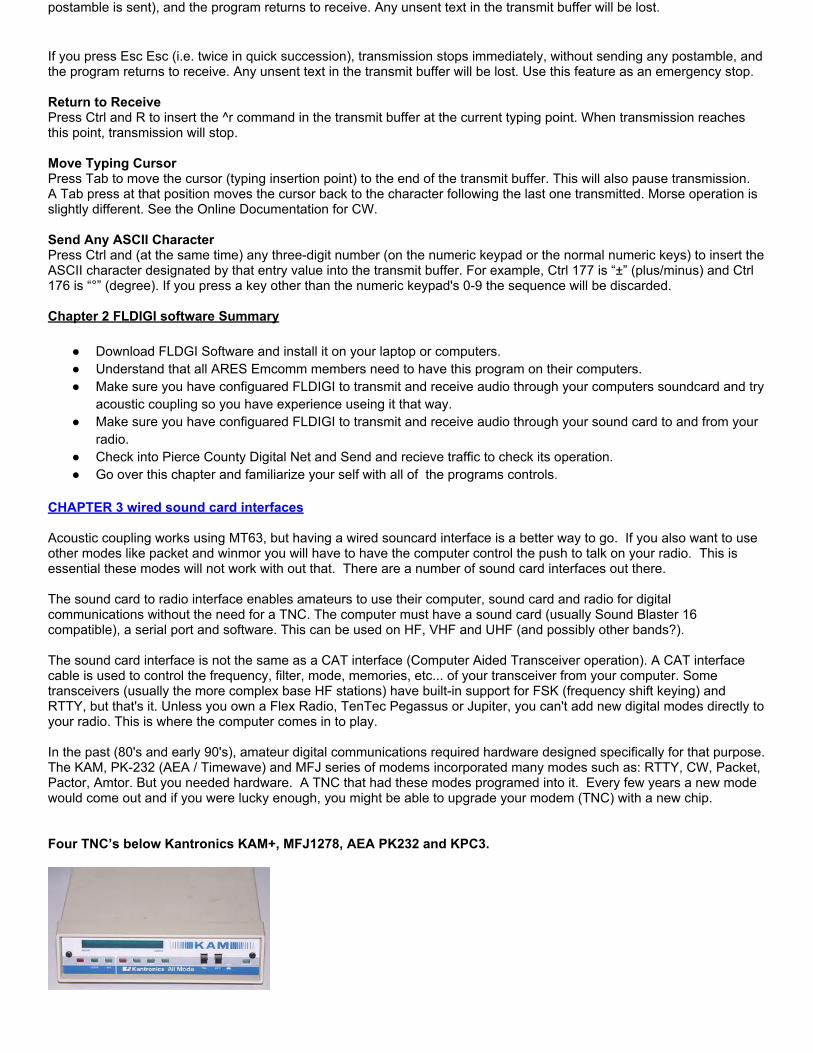
CHAPTER 3 wired sound card interfaces Acoustic coupling works using MT63, but having a wired souncard interface is a better way to go. If you also want to use other modes like packet and winmor you will have to have the computer control the push to talk on your radio. This is essential these modes will not work with out that. There are a number of sound card interfaces out there. The sound card to radio interface enables amateurs to use their computer, sound card and radio for digital communications without the need for a TNC. The computer must have a sound card (usually Sound Blaster 16 compatible), a serial port and software. This can be used on HF, VHF and UHF (and possibly other bands?). The sound card interface is not the same as a CAT interface (Computer Aided Transceiver operation). A CAT interface cable is used to control the frequency, filter, mode, memories, etc... of your transceiver from your computer. Some transceivers (usually the more complex base HF stations) have built-in support for FSK (frequency shift keying) and RTTY, but that's it. Unless you own a Flex Radio, TenTec Pegassus or Jupiter, you can't add new digital modes directly to your radio. This is where the computer comes in to play. In the past (80's and early 90's), amateur digital communications required hardware designed specifically for that purpose. The KAM, PK-232 (AEA / Timewave) and MFJ series of modems incorporated many modes such as: RTTY, CW, Packet, Pactor, Amtor. But you needed hardware. A TNC that had these modes programed into it. Every few years a new mode would come out and if you were lucky enough, you might be able to upgrade your modem (TNC) with a new chip. Four TNC’s below Kantronics KAM+, MFJ1278, AEA PK232 and KPC3.
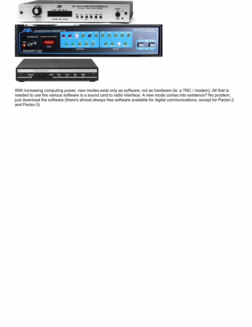
With increasing computing power, new modes exist only as software, not as hardware (ie: a TNC / modem). All that is needed to use the various software is a sound card to radio interface. A new mode comes into existence? No problem, just download the software (there's almost always free software available for digital communications, except for Pactor-2 and Pactor-3)

The sound card interface is used to connect your radio's audio input/output to the sound card's input/output and transfering that audio on to your tranciever. (There also is usually another cable or circuit to trigger the Push To Talk (PTT). The computer is used to create tones (each mode uses different types of tones), send them through the radio, receive tones from the computer and interpret them into intelligble information. In the past, to do any digital communication involved the use of a TNC (or modem) that would be configured for specific modes such as: Pactor, Amtor, RTTY, Fax Various Soundcard interfaces:
The sound card interface will:
● Allow you to do keyboard to keyboard and message communications using your amateur transceiver● Safely connect your PC to radio to avoid feedback, noise, interference, etc...● Give you access to many new ways to use your amateur radio equipment

Most basic simple sound card interface.
Interfacing a soundcard from a computer to a Transceiver does not have to be a complicated matter. Above is the most basic of Sound card interfaces. Keep in mind that just because it is simple does not mean it will work well in every instance.
The above schematic does not allow for a push to talk circuit and provides no RFI isolation between the transceiver and the computer.
It does illustrate how simple it can be.
Digital VOX Sound Card a better Homebrew Interface From an article in March 2011 QST

The final lot of interface kits has now sold out, but you can build your own kit! I still have some mechanical kits, consisting of the circuit
board and case, for $15.00, free shipping. You can pay by PayPal by logging onto PayPal and "Send Money" in the amount of $15.00 to
[email protected]. Please include your shipping address. For the rest of the parts (but excluding cables), you can just place a single order
to Mouser.com per the list shown below.
If you cannot use PayPal, please email me first to confirm that there is still availability and I'll set one aside for you.
73, Skip KH6TY
Transmit audio from the computer is connected to J1, isolated from the transceiver and doubled in value by T1, and then peak rectified by the voltage doubler consisting of D1, D2, C1, and C2, which is used to bias Q1 on, causing it to saturate and pull down the transceiver push-to-talk pin, putting the transceiver into transmit. R5 and VR1 form an attenuator, and VR1 is used to adjust the transmit audio to the right level for a clean transmitted signal. Q1 gets its collector voltage from the transceiver push-to-talk circuit, which must be the common"open-collector" push-to-talk circuit. If this voltage does not exist, the interface will not work.
This interface is intended to be used with all the popular digital modes like PSK31, RTTY, Olivia, etc., which modulate a continuous carrier. For modes that require fast attack and recovery times, such as keyboard CW, Hellschreiber, Packet, or Winmor, a serial port switched interface like the Classic Sound Card Interface in the July 2010 QST should be used instead.

Circuit Board Assembly
Mount and solder all parts to the circuit board as indicated by the legend on the circuit board. Pay close attention to where the "+" ends of the electrolytic capacitors and the black bands of the diodes are placed before soldering. Cut and trim each part after soldering, saving the cutoff ends for making tie points. Mount the resistors and diodes first, then the rest of the parts, and lastly, the tie points. If a hole is accidentally filled with solder, heat the hole to melt the solder, and push a sharp round wooden toothpick into the hole. On the opposite side of the circuit board, melt and draw the solder away from the hole, and when the solder has cooled, withdraw the toothpick, leaving the hole ready to accept another part. Check that there are no solder bridges between adjacent holes, such as those for the transistor or electrolytic capacitors, and melt away any solder bridges with the soldering iron.
( ) Mount and solder resistor R1, 4.7K (yellow, violet, red, gold)
( ) Mount and solder resistor R2, 2.2K (red, red, red, gold).
( ) Mount and solder resistor R3, 680 ohms (blue, gray , brown, gold).
( ) Mount and solder resistor R4, 10K, (brown, black, orange, gold).
( ) Mount and solder resistor R5, 4.7K, (yellow, violet, red, gold).
( ) Mount and solder D1, 1N4148, with band positioned as shown. D1 is next to R1.
( ) Mount and solder D2, 1N4148, with band positioned as shown. D2 is next to D1.
( ) Mount and solder all pins of J1.
( ) Mount and solder all pins of J2.
( ) Solder all pins of pre-mounted T1.
( ) Solder all pins of pre-mounted T2.
( ) Mount and solder electrolytic capacitor C1, 10 uF/50v, with plus end as shown. C1 is next to R1.
( ) Mount and solder electrolytic capacitor C2, 47 uF/50v, with plus end as shown. C2 is next to Q1.
( ) Mount and solder transistor Q1, 2N4401, with flat positioned as shown. Q1 is between the ends of D2 and R2.
( ) Mount and solder 500 ohm potentiometer, VR1.
Tie points are made by bending the lead cut off from a resistor into a "hairpin" shape, inserting it into the two closely-spaced holes on the circuit board, pushing it down to about 3/16" from the top of the circuit board, and soldering both ends of the hairpin
wire on the bottom of the circuit board.
( ) Create a tie point and solder to the two holes marked PTT
( ) Create a tie point and solder to the two holes marked Data in
( ) Create a tie point and solder to the two holes marked Ground
( ) Create a tie point and solder to the two holes marked Data Out
Preparing the Cable to the Transceiver
Decide how long a cable you want to use and cut off the end with the female connector, leaving about 6" of length on the female connector in case you are using an accessory connector, or a microphone connector, other than the 6-pin MiniDin data socket connector supplied with the kit. In this case, plug the male end of the cable into the female end and strip and tin the wires for connecting to the connector you are going to use. On the cut end of the cable, strip about 3/8" of insulation off, and then strip each wire about 3/16" and tin the wires.
Identifying the Wires
If you are using a microphone plug or an accessory plug that has a DC voltage on it, refer to the transceiver manual for the correct pin connections. Do not connect anything to a pin that has a DC voltage on it, unless it is a microphone input pin.
If you are using the MiniDin data jack on the transceiver, identify each wire by first plugging the cable into the transceiver and turning it on. Touch each of the wires, in turn, to the electrical ground of the transceiver. The wire that makes the transceiver go into transmit is the push-to-talk wire.
( ) Solder this wire to the tie point marked "PTT" on the circuit board.
( ) Touch each of the other wires to the now-identified push-to-talk wire. Solder the one that makes the transceiver go into transmit to the "Ground" tie point.
( ) Run the digital software (like FLDIGI or DigiPan - www.digipan.net) and place it in transmit. Verify that you can hear transmit audio coming from the computer speaker.
( ) Connect a stereo audio cable from J1 to the computer speaker or earphone jack and place the transceiver in SSB mode (or FM for FM-only transceivers).
( ) Raise the Windows Volume or Speaker level control slider (and also WAVE slider, if present), until the transceiver switches into transmit.
( ) Using a small screwdriver, turn VR1 fully clockwise.
( ) Touch each of the remaining wires to the tie point marked "Data In" and solder the one that makes the transceiver generate RF output to the "Data In" tie point. If using

an FM-only transceiver, monitor with a second receiver, or scanner, and solder the wire to the tie point that produces a transmit audio sound.
( ) With the transceiver still in transmit, adjust VR1 until the transceiver output power is one-third to one-half of maximum rated power.
( ) Place the software into receive mode.
( ) Connect a stereo audio cable from J2 to the computer microphone jack and raise the Windows microphone level control to maximum.
( ) Touch each of the remaining wires to the tie point marked "Data Out" and solder the one that creates visible noise on the waterfall to the "Data Out" tie point.
( ) Cut off the remaining wires and, if present, the cable shield wire.
( ) Solder one end of the longest cut off part lead into one of the remaining holes without any part soldered in it.
( ) Dress the cable between that hole and the last remaining hole, push the free end of the lead around the cable and into the hole, pull tight, and solder. This will act as a strain relief for the cable. This completes the assembly and wiring of the circuit board.
Modifying the Enclosure
Place the wired circuit board into one half of the enclosure. It will not settle down fully because holes for the jacks and cable need to be drilled.
( ) With a pencil, make a mark where each jack and the cable touches the edge of the enclosure.
( ) Remove the circuit board, snap on the other half of the enclosure, and drill a small pilot hole where the edges of the enclosure top and bottom meet, at the place where you made the pencil marks. Leaving the enclosure snapped together, enlarge the pilot holes to 1/4" diameter. Open the case by inserting a small screwdriver in the indentations where the enclosure halves meet, and twist. Do this on both indentations on one side and the enclosure will pop open. Clear the holes of extra plastic if necessary.
( ) Place the circuit board back into the enclosure. Note which jack is J2, and snap the two halves together.
( ) If not still connected, connect a stereo audio cable from J2 to the computer microphone jack.
( ) If not still connected, connect a stereo audio cable from J1 (the other interface jack) to the computer earphone or speaker jack.
( ) If not still connected, plug the transceiver cable into the transceiver data port, accessory port, or microphone port, depending on which one you are using.

( ) Adjust the Windows Volume Control level until the transceiver goes into transmit when the software is in transmit. The level should be correct from the previous adjustment of VR1. If not, open the case and adjust VR1 until the transceiver is one-third to one-half power, or for an FM-only transceiver, the audio level that is about the same as that for phone operation as heard on a second receiver.
( ) Adjust the Windows Microphone Control level until there is a faint haze of noise on the waterfall. If using DigiPan, it will be yellow on a blue background.
( ) To prevent any possible feedback, it is a good idea to mute both Microphone and Line inputs on the Windows Volume Control panel (not the Recording Control panel, as that is used to control the waterfall signal level).
This completes the assembly and adjustment of the interface. Review each step above if necessary for proper operation of the interface.
Mouser Part Numbers (Quantity needed, part, number):
(1) 2N4401 transistor, 512-2N4401BU
(2) 1N4148 diodes, 512-1N4148
(1) Bourns trimmer potentiometer, 652-3362P-1-501LF
(2) Isolation transformers, 42XL016-RC
(2) Stereo phone jacks, 161-3507-E
(2) 4.7k resistors, 291-4.7K-RC
(1) 680 ohm resistor, 291-680-RC
(1) 10K resistor, 291-10K-RC
(1) 2.2K resistor, 291-2.2K-RC
(1) Electrolytic capacitor, 10 uF, 647-UVR1H100MDD
(1) Electrolytic capacitor, 47 uF, 647-UVR-1H470MED
Audio cables can be purchased at electronic stores and the interface cable can be a PS-2 mouse extension cable.
Every attempt has been made to insure that these part numbers are correct, but please check the part specifications for yourself. I am not responsible for any parts ordered that do not fit the circuit board, or for substitutions that do not work correctly.
Chapter 3 wired sound card interfaces summary

● Understand the difference between a sound card interface and a (TNC) Terminal Node Controller.● Understand that a TNC incorporates the program for the mode used and control over the transceiver● Understand that a sound card only provides an interface between the computer and transceiver and the
programing for the mode and control over the transceiver resides in the software on the computer.● Understand which programs need a TNC and which only requre a Sound card interface.● Understand how the PTT push to talk of your transceiver is controled by the software and why ARQ modes
cannot work without it.● Understand that CAT control of the Transceiver is different than TX/RX Data audio or PTT control and is an
optional control item.● Understand that Sound card interfaces if desired can be very simple wiring. Or complex depending on the
desired features.● Understand that the audio between the transceiver and computer must be adjusted to the proper level.
CHAPTER 4 CUT PASTE SAVE AND MESSAGE STORAGEUse of NOTEPAD text editor. The ability to cut paste and save messages is a basic windows requirement if you want to handle traffic effectively. In fact having a though knowledge of these operations is a big part of being a good operator. It’s whats required to pass and relay traffic in a timely manner. Notepad is a basic text editing program and it is most commonly used to view or edit text files. It is found on all windows operating systems by clicking on the menu button in the lower left hand corner of the computer desktop, then by selecting all programs and click on the accessories folder. A text file is a file type typically identified by the .txt file name extension. The reason its so important to use NOTEPAD when preparing your text for digital messages is that it is the simplest word processor there is. It does not include extra hidden characters in the text to control things such as special graphics, background colors and other similar formating information. These characters might be hidden in an HTML web page or in microsoft word for example, when transmitted over the air it may be received as text which would garble the message. So always use NOTEPAD when drafting your messages. Become familiar with how to save files or messages in folders so you can go back and retrieve them when you need them. You will need to store your messages in folders in the same place. Become familiar with the SAVE AS and the SAVE commands as well as the OPEN command located in the FILE menu in the top tool bar. Each of your messages should include a message number to identify that message from all the rest. You should know how to do all the following:
● Drag and highlight text using your mouse.● Cut text so you can move it to another location, select the text, click the Edit menu, and then click Cut.● To copy text so you can paste it in another location, select the text, click the Edit menu, and then click Copy.● To paste text you have cut or copied, click the location in the file where you want to paste the text, click the Edit
menu, and then click Paste.● To delete text, highlight and select it, click the Edit menu, and then click Delete.● To undo your last action, click the Edit menu, and then click Undo.● Right clicking on the highlighted text will bring up many of these operations in a menu making them easier to
execute. In some screens and programs CUT, COPY and PASTE menu selections are not available.You can still use keyboard commands to get the job done. They are as follows:
Ctrl key + X = cutCtrl key + C = copyCtrl key + V = paste
To see all of your text without scrolling, click the Format menu, and then click Word Wrap. A better method of constructing messages might be to use FLMSG the companion program to FLDIGI. It automates the drafting of NTS and ICS-213 messages and puts them into notepad, email or FLDIGI for you. CHAPTER 4 CUT PASTE SAVE AND MESSAGE STORAGE SUMMARY
● Understand that Windows Notepad should always be used when drafting message text to avoid printing unwanted formatting control characters.
● Understand how to cut, copy, paste, drag highlight, save, save as, right and left click mouse etc to fully use notepad for drafting text.
● Understand how to save your messages to your message folders under Windows so you can open them at a later time.

CHAPTER 5 NTS AND ICS-213 FORMAT - USING FLMSG There are basically two types of message traffic being passed in a disaster. 1. Traffic between the disaster area victims to and from the areas of resources that can help them and 2. Welfare traffic. These are called Welfare Messages appropriately and constitute a large amount of the traffic ARES might be asked to handle.The main use of the National Traffic System would be in welfare messaging. In the event of a major disaster there might be many individuals homeless and forced to move into shelters in the disaster area. With no phones, Internet or other means of normal communications these individuals would need some way to contact family and friends to inform them of their current situation and welfare. If the displaced individuals in a disaster have the email addresses of family and friends then that traffic can go straight through to the family and friends through the Winlink system no problem.
On the other hand if all the shelter resident has is an address and or phone number or the addressee has no email then Winlink will not serve the purpose directly. Human intervention will be needed to deliver that message. That is where the NTS comes in. An NTS RadiogramUsed to deliver an NTS message by mail If phone contact cannot be made.
NTS messages can be relayed on NTS nets by voice or the traffic can be put on Winlink to the state of the intended party directly and it will be picked up and delivered by an NTS station in that state. The FLMSG program helps automate this formating process. A more detailed description of NTS digital system is explained in the Section NTSD - NTS DIGITAL towards the bottom of this chapter. ARES messaging uses either the NTS format or the ICS-213 format. Pierce County ARES currently uses the NTS format with the addition of a from line for the format of all their message traffic. For message traffic moving through the NTS system you would remove this from line as it does not exist in their format. The formating of these NTS messages must conform to the NTS format. It can be helpfull to use a program to somewhat automate the process of this formating. This is where FLMSG can help. It is a companion program to FLDIGI.
FLMSG can be downloaded from:http://www.w1hkj.com/download.html FLMSG settings controls and operationFLMSG is a simple forms management editor for the amateur radio supported standard message formats. These current include: ICS-203 - Organization Assignment List ICS-205 - Incident Radio Communications Plan ICS-205A - Comms List - special USCG Plan ICS-206 - Medical Plan ICS-213 - emergency management report ICS-214 - Unit log ICS-216 - Radio Requirements Worksheet Radiogram - NTS message Plaintext - generic message format Blank - very simple text format with no preset fields Drag and Drop - target control (widget) that accepts either a data file (.203 etc), a wrapped data file (.wrap), or the text associated with a data file. The later may be a copy and paste from another application such as fldigi or a text editor.It's data files are pure ASCII text that can be sent from point to point using the internet, amateur radio, or other electronic link. The data files are designed to minimize the transfer size. This is particularly important on amateur HF. The data file and the transfer file are one in the same, but can be further encapsulated using either flarq or wrap for the purpose of confirming the received file integrity. File:New - clear all fields and name the default file "new.f2s" (new.m2s for radiogram)Open - open an existing file flmsg data files have the extension ".203" for ICS-203 forms".205" for ICS-205 forms".25A" for ICS-206A forms".206" for ICS-206 forms".213" for ICS-213 forms".214" for ICS-214 forms".216" for ICS-216 forms".m2s", read as "message 2 send" for radiogram forms".p2s" for plain text, generic forms".b2s" for blank forms Save - save the current file to the name in the "file:" display box Save As - save using a new filename that the user provides View- write the data to specified type of file Html delivery - viewed in default browser, contains only those elements sent to final recipient Html file copy - viewed in default browser, contains ALL fields including record keeping Text - viewed in default text editor - suitable for CW / Voice transmission Q-forms Import - Import the data fields from a Qforms eXtended Markup Language (xml) file Export - Export the data fields to a Qforms compatible xml file Wrap (Import / Export / AutoSend)
Import the data fields from a Wrapped data file. If the data file is corrupt you will be given the opportunity to either allow flmsg to recover as many fields as possible or to view the file using the default text editor. Export the data fields to a Wrapped data file Auto send Create a wrapped datafile and save in the NBEMS.files/WRAP/auto directory. If running, fldigi will find and automatically transmit the file. Template: Load - load an existing template file - the default extension for the supported files are:

ICS-203 template- ".203T" ICS-205 template - ".205T" ICS-205A template - ".25T" ICS-206 template - ".206T" ICS-213 template - ".213T" ICS-214 template - ".214T" ICS-216 template - ".216T" Radiogram template - ".m2t" Plain text template - ".p2t" Blank text template - ".b2t" Save - save the current form as a template file, using the default (or current) filenameSave As - save the current form as a template file, user provides the filenam Config: Open the configuration dialog Note: data files and template files for ICS213 are identical. The only difference is their location in the computer directory structure and their extension. Message files and template files maintain their uniqueness by virture of their file name. If you reuse a filename the old data will be lost. File locations: On XP: C:\Documents and Settings\<username>\NBEMS.files On Vista: C:\Users\<username>NBEMS.files On Linux: /home/<username>/.nbems On Puppy: /root/.nbems On OS X: /home/<username>/.nbems Data files are located in the sub directory "ICS/messages"Template files are located in the sub directory "ICS/templates"View files (.rtf, .html, .txt) are located in the "ICS/" subdirectory. Configuring flmsgThe configuration items for flmsg are just a few and can be changed on the configuration dialog: Date format - select the date format that will be used for both ICS213 and RadiogramTime format - select the time format that will be used for both ICS213 and RadiogramRadiogram format - Fill in the data relating to the originating amateur station # words per line to be used when formating the radiogram message textWrap - automatically open the target folder (directory) when the file is exportedNaming files - automatic file name generation as: CALLSIGN-YYYYMMDD-HHMMSS(Z)-NNNN where CALLSIGN is the operators callsign YYYYMMDD is year, day, month HHMMSS is hours, minutes, seconds local or Zulu at time file is created NNNN is an auto incremented serial number
You can elect to use any or none of the autogeneration componentsFilename extensions are f2s for ICS-213 data, f2t for ICS-213 templates andm2s for radiogram data.
Radiogram serial numbers can be auto-incremented. The auto-increment number is also used for the file name. In the example shown the next Radiogram will be number 104 and the associated file sill be W1HKJ-104.m2s Qform data fileflmsg can read and write Qform ICS213 data files. The Qform data file is larger by virtue of the xml structure. The file size ratio is less when the content is larger. Viewing the data in a printable formatThe program can produce a viewable document in ASCII text and Hypertext Markup Language (html) file formats. After creating the document flmsg will request the file to be opened by the default viewer / editor for that type of document. Html Text Format

The html Text Format file that the File/Write menu item produces can be opened with any web browser program. Use that software for printing the report.

NTSD - NTS DIGITAL
6.1 NATIONAL TRAFFIC SYSTEM - DIGITAL NTS Digital (NTSD) is currently configured as a parallel system to the manually operated NTS nets, providing 24 hour continuous service as links between Regions through manned BBS stations operating on multiple HF bands. Hubs in each of the three U.S. NTS Areas, Eastern, Central and Pacific, are key stations in the Area interconnects. The Regional NTSD stations have access to and from Section level liaison packet operators by way of VHF/UHF packet interfaces. These packet liaisons carry traffic to and from the Local and Section NTS manual nets, thus providing the links to origination and delivery. Area and Region digital coordinators are assigned to manage the system throughout the NTS. Since they are manned stations, traffic routed via the NTSD is monitored to assure that traffic is kept moving, and any path loss is circumvented by manual intervention... the traffic being diverted to the manual nets as necessary.
Digital stations are unmanned and are available 24/7 to accept traffic and forward it on via the Winlink system. These stations often operate with scanning radios capable of being accessed on the optimal band for the path desired for that time of day. Although there is a variety of software available for such BBS operation, numerous stations are using WinLink as a platform and Pactor or now Winmor as the HF mode. VHF/UHF links are often via normal ground packet direct, or via a large variety of packet node station interconnections. NTSD handles only ARRL formatted formal radiograms. The following overview of NTSD operation is provided by the former Third Region Digital Coordinator, N3QA, and the Eastern Area Digital Coordinator, N4SS. All call signs used in this manual are intended to be generic for tutorial purposes and not related to the holders of those call signs in any way. 6.2 PROTOCOL FOR NTS DIGITAL STATION OPERATIONS----- 6.2.1 ARRL STANDARD MESSAGE UPLOADING Sample ARRL Formatted Message for Digital Winlink Systems. Note that the entire message, including preamble, address, text and signature, is uploaded in the TEXT upload to the digital system. The “TO” and “SUBJ” fields are used for routing purposes. (BBS prompt: Enter “To” line.) (Notes.) SP 99999@NTSCA <enter> TO: upload line. Subj. QTC SOMETOWN / 555 555 <enter> SUBJECT: upload line. Msg. MSG.: field lines: NR 1 R HXG N3QA ARL 5 CHESTERTOWN MD JAN 1 Preamble.. GUY ANYONE Address 123 MAIN STREET SOMETOWN CA 99999 555 555 5555 < BT, text start

ARL FIFTY SEE YOU SOON Text <BT, text end JOHN Q PUBLIC Signature < blank line for clarity /EX <enter> UPLOAD, message end. (Text example with OP NOTEs shown.) (Text field) NR 1 R HXG N3QA ARL 5 CHESTERTOWN MD JAN 1 Preamble GUY ANYONE Address 123 MAIN STREET SOMETOWN CA 99999 555 555 5555 OP NOTE DELIVER ON WEEK DAYS Address OP NOTE < BT, text start ARL FIFTY SEE YOU SOON (text) < BT, text end JOHN Q PUBLIC Signature OP NOTE REPLY VIA N3QA 3RD REGION NTSD Signature OP NOTE < blank line, no characters /EX <enter> UPLOADS message, end. Once the BBS sees the /EX at the start of a new line, your message will be acknowledged and stored on the BBS for forwarding. You may then enter another message by using the "ST or SP......” command again or end the connection by using the "B" for Bye command. NOTES: ST (S)end (T)raffic - or SP (S)end (Personal)“To” line introducer, used to indicate anNTS message, followed by a space.Note on the winlink stations i have used. The stations will not accept the ST command so you have to use the SP command. Non Winlink packet systems will take ST but will probably not forward past that station. SP 99999@NTSCA To: Destination Zip Code and the letters NTS followed by the STATE (not ARRL Section) abbreviation of the destination. There may be spaces between the parts, i.e., 99999 @ NTSCA. QTC QTC (message): Subject line introducer, followed by a space. QTC SOMETOWN / (555-555) Subject line. Town of the destination and the area code and prefix of the phone, or “NO PHONE”, and/or call sign of an amateur addressee; 30 characters max., including the QTC. NR (#) NR, space, (#): Serial number of your message. Usually starts with "1" at the beginning of a year or month. Preamble starts at this point. TEST R (Precedence) Welfare precedence. The Welfare precedence level for message traffic. Others: Routine, Priority, Welfare, EMERGENCY. The word TEST precedes the precedence for exercise messages. HXE (HandlingInstructions) Delivering station get reply from addressee, originate message back. KJ7UI (Stn-of-Orig) Call sign of the station originating the message. ARL 5 (Check) Check (word count) of the text portion of the message. In this case the ARL indicates that the message contains an ARRL Numbered Radiogram text. There are many ARL numbered messages to make the message transmission shorter.
GIG HARBOR WA Place-of-Origin. Place where the message originated (the location of the person for whom the message is originated). (Opt. Time-Filed) Not shown. 24 hour UTC unless marked PST, etc. (1830PDT), placed just before a space before the month. JAN 1 Month and day the message originated, UTC unless Time Filed is not Z, then time and date must agree. Preamble ends at this point following the day figure(s). TO ADDRESS: The name, address, and telephone number of the addressee follow the preamble. Address begins on a new line. Address OP NOTE Follows the end of the address if needed (re delivery). New line. (BT) Blank line marks the start of the text. A “BT” may optionally be used on a line of its own as a break between the address and the text (for those who use software with BT’s to generate their messages). The “BT” is consistent with the <BT> and “BREAK”. TEXT: Next comes the text of the message. (Note that exercise message texts contain the words “test message”, or “exercise” as the first and last groups of the text. (BT) Blank line marks the end of the text. A “BT” may optionally be used as a break between the text and signature (as above). SIGNATURE: Name of the person(s) sending the message. Signature OP NOTE Follows the signature if needed (re reply). New line. (/EX spacing) Blank line precedes the following “/EX” for clarity (no characters.). /EX The characters which tell the BBS that the message is ended. The "/EX" or "/ex" must be the only characters at the beginning of a new line. Commands may be in upper or lower case.

As formated for a manual packet connection to a Winlink station: SP 92154@NTSCA QTC 1 W SAN DIEGO CA (619-424) 1 TEST W HXE KJ7UI ARL 22 GIG HARBOR WA 18:26L JUN 15JOE SMITH1234 MAIN STSAN DIEGO CA 92154(619)424-1234BTEXERCISE MSG X ARL ONEX ARL SIX X ARLSIXTEEN X WILL WRITE YOUMORE WHEN I CAN XEXERCISE MSGBTKATHLEEN SMITH/EX In an automatic B2F protocol program such as AIRMAIL and Winmor RMS Express the special codes SP and /EX are done for you automatically so would not be included. * Message formatting on the digital modes is best done with a simple, but precise, method. In the above example note that there is no line space between the preamble section and the address section. There is a BT between the address and the text section and a second BT between the text section and the signature section of the message. Keep the message text to five (5) words per line. That makes confirming the word count, or check, simple for the receiving operator. As delivered in formal message, in email or by mail.
ONE SINGLE MESSAGE PER UPLOAD Booking is considered poor practice on digital systems and is difficult to process at the delivery point. Booking means sending many messages to the same town, area code and prefix in one saved message. Instead send separte saved messages. A /EX must follow each message so each one will be saved separately. CHAPTER 5 NTS AND ICS-213 FORMAT - USING FLMSG SUMMARY
● Download FLMSG and install it on your computer
● Review FLMSG commands and features and become familar with its radiogram message generator.● Understand how to print finished text to File+View+plain text and HTML text windows ● Understand Welfare Routine priority and emergency precedence● Understand ARES role in handling welfare traffic and the importance of human intervention● Understand the NTS format● Understand the ICS-213 format● Understand that NTS will not accept traffic unless it is in NTS format.● Understand the difference between a manual and an automatic connection to Winlink● Understand how to address a manual message on Winlink to an Email address.● Understand how to address a manual message to a Winlink user callsign● Understand how to address a manual message to a state via the NTSD
CHAPTER 6. MULTIPSK... PACKET USING ONLY A SOUNDCARD
Packet Radio Is communications between computers using radio (RF) as the medium rather than wires or solid mediums. Your personal computer in your ham shack coupled to your VHF or UHF transceiver via a terminal node controller (TNC) is the makeup of the Packet Radio station. There are now programs available to use the soundcard in your computer in lieu of an outboard TNC. Packet Radio is a product of the computer age, and as a result, Packet Radio has computer-age features that provide a very efficient means of Communication. Packet Radio provides error-free communications. With Packet Radio, no time is wasted trying to decipher communications that contain "hits' or "misses" caused by electrical interference or changes in propagation. The receiving station receives information exactly as it is sent by the transmitting station or it doesn’t recieve the message at all..

Packet is communications between people either direct or indirect. You can work keyboard to keyboard or use electronic mailboxes to leave messages. Due to error checking by the TNC, all of it is error free, too. As the data is received it is continuously checked for errors, and isn't accepted unless it is correct. You don't miss the information if it has errors because the information is resent again. The data that is to be transmitted is collected by the TNC and sent in bursts, or packets, of information; hence the name. Each packet has the callsign or address of who it's going to, who it's coming from and the route between the two stations included, along with the data and error checking. Since up to 256 characters can be included in each packet, more than three lines of text can be sent in a matter of a couple of seconds. There is plenty of time between packets for several stations to be using the same frequency at the same time. Packet Radio is gaining resurgence as a very viable means for emergency communications. New programs enabling email by amateur radio and other message programs are gaining popularity among emergency communications units. The Department of Homeland Security, The Federal Government along with State and Local entities are becoming very interested in this form of communications to supplement emergency communications in disasters. Winlink 2000 (WL2K) - is a worldwide system of volunteer resources supporting e-mail by radio, with non-commercial links to internet e-mail. These resources come from Amateur Radio, the Military Auxiliary Radio System (MARS), and other volunteer organizations. The system provides valuable service to emergency communicators, and to licensed radio operators without access to the internet. The all-volunteer Winlink Development Team (WDT) is committed to continuous improvement using modern computer and networking technology with the most efficient and effective radio modes and digital protocols for local, regional and long-distance applications. The most popular emcomm digital mode by far is 1200 baud packet. But, most commonly, to do packet requires a TNC modem. That costs anywhere from $50 to $400. That keeps many emcomm amateurs out of the mode. You must have packet if you want to pass message traffic by VHF/UHF on Winlink direct without someone relaying for you. There are two ways to beat the high cost of a packet TNC. One of them is a free version of the program AGWPE. I guess it works for some people but i gave up trying to get it to work for me. The other way is a program called MultiPSK. It offers many different soundcard modes but is the only one that offers packet as part of it. And it works .... it is not the easiest program but heh ... its free! MultiPSK for Packet using a soundcard interface can be downloaded for free at:http://f6cte.free.fr/index_anglais.htm MultiPSK is a multimode programModes supported by Multipsk: Phase Shift Keying modes:BPSK: BPSK31-63-125-250 / CHIP (64/128) / PSK10 / PSKFEC31 / PSKAM10-31-50BPSK with SSTV: PSK63 F - PSK220F + DIGISSTV "Run"QPSK: QPSK31-63-125-250MPSK: MT63PACKET BPSK1200-250-63-31 + APRS+ DIGISSTV "Run"MIL-STD-188-110A - 4285HFDLOn-Off Keying Modes: CW / CCW-OOK / CCW-FSK / QRSSFrequency Shift Keying modes:PACKET: 110-300-1200 bauds + APRS+ DIGISSTV "Run"PACTOR 1 / AMTOR FEC-Navtex / AMTOR ARQ / SITOR AASCII / RTTY 45-50-75-100-110-150-200 / SYNOP + SHIP / IEC 870-51382 / GMDSS DSC / ACARS (VHF) / DGPS / NWR SAMEMulti Frequency Shift Keying modes:MFSK8 / MFSK16 (+SSTV)OLIVIA / Contestia / RTTYM / VOICETHROB/THROBXDominoF / DominoEXPAX / PAX2Automatic Link Establishment (see http://www.hflink.com) MIL-STD-188-141A+ ARQ FAE / ALE400 + ARQ FAEDTMF, SELCALJT65 (A B and C)COQUELETHellschreiber modes: FELD HELL / FM HELL(105-245) / PSK HELL / HELL 80 Graphic modes: HF FAX / SSTV / PSK SSTV modes (mentioned above) / MFSK16 SSTV (mentioned above) DSP modes: Filters / Analysis / Binaural CW reception

RTTY, CW, BPSK31, BPSK63 and PSKFEC31 Panoramics Identifiers: Video ID / RS ID / Call IDTCP/IP digital modemIntegered SdR demodulator/modulator MultiPSK article From January 2004 QST © ARRL Steve Ford, WB8IMY QST EditorIs there such a thing as a free lunch? In the world of Ama-teur Radio software, it does occasionally happen. Take Patrick Lindecker, F6CTE. He has developed a sound- card application for Windows known as MultiPSK. Thanks to some clever coding, MultiPSK allows you to converse with a cornucopia of digital modes including BPSK31, QPSK31, PSK63, PSK10, PSKFEC31, CW, Coherent CW, SSTV, RTTY, AMTOR (FEC) and Hellschrieber. It also includes receive- only ability with several other modes such as AMTOR (ARQ), NAVTEX and more. MultiPSK adds contact logging, with ADIF exporting for ARRL’s Logbook of The World, and even DSP audio filtering. Perhaps the most remarkable thing about MultiPSK is that it is 100% free—no strings attached. Patrick has written some interesting features into MultiPSK that are generally not found in other multimode programs. For example, not every amateur owns a powerhouse PC, so MultiPSK can adapt to slower machines. If you’re using a 166 MHz Pentium, for example, you can click a button in the main window and MultiPSK will reconfigure accordingly. MultiPSK runs best with at least a 450 MHz Pentium, but it can function with a 66 MHz PC if necessary. MultiPSK can print the active window at any time by click-ing on a single button. This can be convenient when you need to preserve the text to paper. The print function prints the en-tire window, however, including graphic elements such as the buttons, etc. With MultiPSK you can choose a “panoramic” display that will decode (“translate,” as Patrick calls it) two dozen QSOs at the same time. The traditional waterfall display and a spec-tral display are available as well. Performance I was able to try MultiPSK in several modes and found it to be a very capable program. PSK31 performance was excellent. The panoramic mode was fascinating, although it was confus-ing to wade through so many simultaneous streams of text. The familiar vertical waterfall display seemed to work best for me. RTTY reception was good. It isn’t at the performance level of something like MMTTY, but I think MultiPSK would be ad-equate for most contest and DX operating. SSTV with MultiPSK was a blast. Tuning is easy with the spectrum display and slant correction was simple and straight-forward. (A couple of mouse clicks and you’re done.) On CW, MultiPSK offered adequate copy as long as the sending is perfect. No surprises here. I’ve yet to see software that can copy sloppy sending as well as the wetware between your ears. I tried Coherent CW, but I couldn’t find anyone operating CCW during the review period. The DSP audio filters were fun to play with. Many modern transceivers have DSP filtering built-in, but with MultiPSK you gain some additional performance and flexibility. Hits and Misses MultiPSK hits the target when it comes to flexibility and overall performance. Patrick has written MultiPSK with the idea of giving users as many choices as possible. Unique conveniences, such as a button to “release” the sound card so that other applications can use it without shutting down MultiPSK, really shine. Misses include the lack of the MFSK and MT63 modes. (Note both modes were added including Packet after this article.) Neither mode has a large following, but you will hear them on the air from time to time. Also, Patrick has done his best to translate the button labels and help text from French to En-glish, but there are several instances where the translation doesn’t quite work. This can be a little jarring. I found myself pondering a couple of sentences on the help screens, trying to discern what Patrick really intended to say. But as a friend of mine used to say, “Wadda ya want? It’s free, fer cryin’ out loud!” That’s the point you need to keep in mind when using MultiPSK. For a freeware application, the positives far exceed the negatives. Manufacturer: Patrick Lindecker, F6CTE. Download from the Web at members.aol.com/f6cte/. Download is 1.42 Mbytes in a ZIP file. SENDING PACKET EMAIL ON WINLINK USING MULTIPSK (FREE VERSION)===================================================Download MultiPSK free at:http://f6cte.free.fr/index_anglais.htm Install and set up the program and get it working with your sound card interface.You must have a wired interface with PTT or transmit to your transceiver controlled by the software. Make sure that you can receive and transmit audio and that the software can control PTT on your radio. Select the PACKET button from the mode buttons on the right hand side of the RX/TX page Our example uses a connection to WA7FW-10 Fire Station 62 in Federal Way, WAPut WA7FW-10 callsign in the destination window and your call sign in sender window. Once you have it set up try connecting to the WA7FW-10 winlink station on 144.93 Mhz

by selecting the CONNECT button. YOU CONNECT TO THE WINLINK STATION and what you see will be this Thanks for using WA7FW-1Ø located at Fire Station 62 in Federal Way [WL2K-2.4.Ø.6-B2FIHJM$] Halifax CMS via WA7FW-1Ø > What your looking for is the > caret or command prompt...That means the station is ready to recieve a command from your station. TO SEND A MESSAGE YOU MUST USE THE SP COMMAND WITH THIS PROTOCAL:SP <CALLSIGN> OR SP SMTP:<[email protected]>. THE SP MUST BE THE FIRST THINGTHAT IS SENT AFTER YOU CONNECT OTHERWISE IT WILL NOT WORK. NO LINES ABOVE OR SPACES IN FRONT OF THE SP COMMAND OR IT WILL NOT RECOGNISE IT. THE SUBJECT LINE IMMEDIATELY FOLLOWS ON THE NEXT LINE BY ITSELF. THEN A SPACE LINE AND THE MESSAGE IT SELF FOLLOWED BY /EX ON A LINE BY ITSELF. THE SPACE LINE JUST MAKES FOR A MORE VISUALLY PLEASING PRESENTATION AND HELPS TO GIVE A VISUAL REFERENCE. THIS CAN ALL BE TEXT EDITED IN A NOTEPAD FILE AND CAN BE COPIED AND PASTED INTO MULTIPSK. ONE OF THE BAD THINGS ABOUT MPSK IS IT SUCKS AT CUTTING AND PASTING. SO YOU HAVE TO DO THINGS A LITTLE DIFFERENT TO ACCOMPLISH THIS. YOU CAN WRITE UP YOUR MESSAGE IN NOTEPAD AND THEN SAVE IT AND LOAD IT INTO THE XMIT WINDOW BY RECALLING THE SAVED FILE WITH THE FILE BUTTON JUST ABOVE THE TRANSMIT WINDOW AND THIS WILL SEND YOUR FILE OUT TO BE TRANSMITTED. ANOTHER WAY IS TO USE ONE OF THE MACRO BUTTONS JUST ABOVE THE TX WINDOW. I LIKE THE F12 WINDOW. RIGHT CLIC ON IT AND A MACRO WINDOW WILL OPEN WITH A LIST OF MACROS THAT CAN BE USED WITH THIS BUTTON REPLACE WHATS THERE WITH <CLRTX><TX> THIS MACRO WILL CLEAR THE TX WINDOW OF ANYTHING PREVIOUS AND THEN TX THE TEXT THAT FOLLOWS THAT COMMAND. SO JUST CUT AND PASTE INTO THIS MACRO WINDOW SAVE IT AND LEFT CLICK ON THE F12 KEY TO SEND THE CONTENTS. I KNOW YOU WOULD THINK THAT A PROGRAM LIKE THIS WOULD INCLUDE SIMPLE CUT AND PASTE INTO ITS WINDOWS. WHEN YOU FORMAT A BASIC MESSAGE IT SHOULD TAKE THIS FORM SP W7ABCGOT YOUR MESSAGE HI I GOT THE MESSAGETHAT YOU SENT. WILLSEND YOU BACK A MESSAGEWHEN I HAVE THE TIME /EX YOU XMIT: HIT MACRO KEY "F12"That xmits the contents of that file into the transmit window sending it out. Halifax CMS via WA7FW-1Ø > Enter subject line for new message: Enter the message body ending with /EX on a separate line: Your message 5WQPØ9N6YPPU has been sent... YOUR LOOKING FOR THE Your message 5WQPØ9N6YPPU has been sent

THAT MEANS IT WAS SAVED TO THE SYSTEM IF YOU DONT GET THE ABOVE MESSAGE TRY SENDING A /EX AGAIN YOU XMIT: B WHICH IS THE BYE OR DISCONNECT CMD. Halifax CMS via WA7FW-1Ø > Disconnecting... RECIEVING MAIL ON WINLINK====================================================Thanks for using WA7FW-1Ø located at Fire Station 62 in Federal Way [WL2K-2.4.Ø.6-B2FIHJM$] Halifax CMS via WA7FW-1Ø > LM [WL2K-2.4.Ø.6-B2FIHJM$]SanDiego CMS via WA7FW-1Ø > K8K9GSJS8GVW 2Ø1Ø/11/Ø1 17:Ø9 762 SMTP:[email protected] Re: Test message RM SanDiego CMS via WA7FW-1Ø > Message ID: K8K9GSJS8GVW Date: 2Ø1Ø/11/Ø1 17:Ø9 From: SMTP:[email protected] To: KJ7UI Source: SMTP CMS Site: SanDiegoSubject: Re: Test message We have set up at the disaster assistance site now, and we are running on generator power.The cell mobile phone comms, landlines, and VHF repeater coverage is notavailable here, so you may contact us via reply email (text only) and wewill receive it via HF email. Signed, Al KJ7UI /EX KM SanDiego CMS via WA7FW-1Ø > Message removal completed... B SanDiego CMS via WA7FW-1Ø > Disconnecting...
EXPLANATION OF PACKET COMMANDS======================================================FOR WINLINK STATIONSSP SEND PERSONAL SP SMTP:<[email protected]> for sending to a regular email address SP <CALLSIGN> where the Callsign your are sending to is a registered winlink user. SP <[email protected]> The long version of above method/EX This is used to end and save a message you have just transmitted. It tells the packet station that is the end of your message and that you want to save it.LM LIST MINE, LIST ALL MESSAGES ADDRESSED TO YOUR CALLSIGNRM READ MINE, READS ALL MESSAGES ADDRESSED TO YOUR CALL SIGN R 5 Where you only want to read message number 5.KM KILL MINE, DELETES ALL MESSAGES ADDRESSED TO YOUR CALL SIGN K 5 Where you only want to kill or erase message nember 5B BYE, DISCONNECTS YOUR STATION FROM THE WINLINK STATION ======================================================FOR NON WINLINK REGULAR PACKET STATIONSSP SEND PERSONAL Can be SP KJ7UI@KJ7UI-1 call sign of person your sending to and bbs where you are connecting to.ST SEND TRAFFIC Used to send traffic so any station can pick it up and read it. Used to relay traffic when you don't know who will be the relay station.SB SEND BULLETIN SB CATAGORY@KJ7UI-1H or ? usually means to request help file which will give you many more commands with more options than the basic ones listed here.J JUST HEARD will give you a list of stations that the station you are connected to has heard on frequency. CHAPTER 6. MULTIPSK... PACKET USING ONLY A SOUNDCARD SUMMARY
● Download and install MultiPSK and get it operational● Understand review manual packet commands and when to use them● Make a manual packet connection to a Winlink station and upload and download a message.● Understand that MultiPSK is a Multimode program that offers many different modes not just packet.
CHAPTER 7 Packet and WinlinkYou must apply for and get a free Winlink account. Once you have applied for this account you need to connect via a radio connection to verify the account to be able to use it. Also remember to connect every month or so just to keep your account up to date. If you go for something like six months without using the account, it will expire. You can send email from your radio station thru to anyone that has an email address or more simple to any hams callsign who has a Winlink account. Go to the Winlink website:http://www.winlink.org/ Getting started with Winlink:http://www.winlink.org/GetStarted How to get a Winlink RADIO e-mail account from the Winlink websiteThere are a number of ways to get started using Winlink 2000 radio e-mail. But before we list them, you should be aware of these points: You can not apply for a radio email account anywhere online. Winlink 2000 is a RADIO e-mail service for licensed radio operators, and is NOT an internet "common carrier". To create a radio e-mail account you must use radio e-mail client software and make a connection using a RADIO, or a Telnet connection directly to one of our Common Message Servers with correctly configured client software. See the section in the next chapter of this course on configuaring Telnet. This process is not supposed to be "internet easy", and is intended to both validate on-air radio stations and to prevent abuse by unlicensed users. Online Webmail is a limited feature offered to established Winlink radio email users when they are separated from their stations. Webmail access becomes available to users only after they have established a radio e-mail account, and after they request a password at the webmail portal online. Accounts with webmail- or server-only access are not available.And last, you need an amateur radio license to use this system. See the amateur radio licensing authority in your country for information. If you live in the USA, go to this site: http://www.hello-radio.comUsers found using invalid or pirated callsigns will be turned over to the appropriate authorities, and their service terminated. If you are without a local ham or mentor who can guide you (highly recommended!), we suggest you follow this general approach:

To establish your WL2K radio email account you must load user software, Airmail software or Winmor RMS Express work good, configure it properly, and then send a message by connecting to a WL2K RMS radio gateway or CMS telnet port. Send your first message to any email address that already exists (we recommend your main internet e-mail account.) Afterwards, you will be able to receive radio e-mails at your new WL2K address [[email protected]]. Proper software configuration and radio station setup is absolutely necessary! To prevent frustration, we strongly suggest you read further. Give your learning curve a chance and take advantage of the available help! If you are interested in Emergency Communications using Winlink, and particularly packet radio, check out "Winlink for the Digitally Challenged". This online course will take you step-by-step through downloading and installing client software, establishing your WL2K e-mail account, and using the software to send and receive messages using the internet and without a radio. When you feel comfortable with the software, you can move ahead with connecting your radio and TNC/modem, and going on the air.

8. AIRMAIL PROGRAM - PACKET OR PACTOR USING A TNCAirMail is a radio mail program for sending and receiving messages via Pactor over HF radio, or, Packet over VHF/UHF either via the ham radio system or participating marine and commercial services. AIRMAIL Packet and Pactor software to be used with a TNC. http://www.airmail2000.com/ Airmail is a messaging program (similar to Outlook) specifically designed for connection to a HF or VHF radio mailbox station. Once connected to a compatible station, message transfer is completely automatic. On the ham bands, Airmail can transfer messages automatically with any station supporting the BBS or F6FBB protocols, such as Winlink-2000 (www.winlink.org), Winlink, F6FBB and MSYS and other Airmail stations. Airmail is also used as the client program by the SailMail marine system and other participating systems. A "dumb terminal" mode is also provided but ordinary QSO's are not the program's forte. Airmail is a 32-bit program which runs under Windows-95, 98, NT, 2000 or XP. Airmail supports the SCS PTC-II and PTC-IIe Pactor-2 modems as well as the original PTC Pactor modem, the Kantronics KAM+ and KAM-98, AEA/Timewave PK-232, PK-900, DSP-1232 and 2232, the MFJ 1276 and 1278B, and the HAL DXP-38 Clover/Pactor modem. (Sound cards are not supported). Airmail is a program developed specifically for sending messages via HF radio and optimized for low-speed links, not an adaptation of an ordinary email. Airmail is written and supported by Jim Corenman, a cruising sailor who developed the program in an environment that rewarded efficient wireless communications- far from wired Internet connections. AirMail is licensed without charge to the amateur radio community and is dedicated to the many sysops who have donated generously of their time and equipment to make the digital ham radio network a reality. System RequirementsAirmail requires a PC-compatible computer running Windows-95 or later. The computer must be equipped with adequate memory (see Windows Performace issues).A compatible Pactor modem must be connected to a serial port accessible to Windows and also to a digital-capable SSB transceiver. Many older SSB transceivers (ham or marine) are not capable of continuous full-power transmission and must be operated at reduced power (see Audio levels). In case of doubt check the radio manual or seek assistance from the manufacturer or dealer. Compatible modems: SCS PTC-II, IIe, or IIpro Kantronics KAM+, KAM with "enhancement board, or KAM-98AEA PK-232mbx, PK-900, DSP1232/2232 (firmware must include Pactor mode, and ver 7.1 or later firmware is needed to use binary mode)MFJ 1276 or 1278B (ASCII modes only)HAL DXP-38SCS PTC-plus (Pactor-1), ASCII modes onlyCurrent firmware is generally required. Airmail is also capable of automatically setting the dial frequency of compatible transceivers when stations and frequencies are selected. This is strictly optional and requires a compatible transceiver and suitable CAT or CI-V interface. Program InstallationIf you have not yet installed Airmail, that is the next step. AirMail is installed from two install files. The first installs required system files and need only be installed once, the first time Airmail Version 3 is installed. (If the previous installation was Version 2, then the system files must be installed). The second is the Airmailprogram and settings files. Simply double-click each install file and follow the prompts. The Airmail install program will check for previous installations and offer a choice of installation directories. It is recommended that you stick with the default installation folder of C:\Program Files\Airmail to avoid future confusion. AirMail uses a conventional ".ini" file for settings rather than the stylish-but-aggravating practice of burying settings in the system registry. The initial settings are contained in an initial Airmail.ini file which is installed only if there is no previous file. Settings will not be changed if Airmail is re-installed or updated. (If you wish to reset the settings file to the original defaults, delete the Airmail.ini file and resinstall Airmail). The address book is contained in the file addrbook.txt, which can be copied or saved. (Airmail can also import or export addresses in a format compatible with many email programs).

To bring up the Telnet window click on the lightening icon in the tool bar. When the Telnet window comes up click the settings button. Configuaring TelnetTo get up quickly on Telnet so you can register for your Winlink account you will need to configuare Telnet settings to the following: Remote Callsign: WL2KSRemote Host: sandiego.winlink.orgPort: 8772Timeout: 120Local Callsign: your callPassword CMSTELNETProtocol: B2 Telnet is pretty much basic email its just that it goes through the Winlink system. To Send your first email in Airmail Telnet go to the icon in the toolbar that looks like a sheet of white paper click on it and the message window will come up. The address book will be in the middle of the page cancel it. Put your email address in the TO window and something like TEST in the SUBJECT window. Now put any text message you like in the main text area and your almost done. Now post the message for sending by clicking on the icon that looks like a mailbox in the toolbar.Now click on the lightening icon in the tool bar and the Telnet window will come up. Click on the “Green connect button. If you set up the telnet settings correctly you wil see the connect text : Callsign :Your CallsignPassword :********[WL2K-2.7.0.0-B2FWIHJM$];PQ: 62174857SanDiego CMS >[AirMail-3.4.034-B2FHIM$];PR: 16173111; WL2KS de KJ7UI (CN87qg)FF“Test” message sentFQ2011/06/19 02:22:17 Telnet Port Disconnected This means everything went as it should and you will now be registered with Winlink as a user.You must keep up your account with periodic usage or it will expire. Overview of AirMail Windows and FeaturesThe AirMail program has two principal windows, a "Main Window" for viewing and editing messages, and a "Terminal Window" for communicating via radio with mailbox stations and other Pactor stations. Principle features include:
● A Setup Wizard to help get set up and on the air quickly. ● A Message Index window for easy access to incoming and outgoing messages, with Message Icons to provide
feedback on message type and status. ● An Explorer-style Folder Tree facilitates storing and retrieving messages, including separate folders (directories)
for saved messages and trash you never wanted to see again. Either a single folder or a mix of folders can be open, the initial setting is for the Inbox, Outbox and Bulletin folders to all be open together.
● Message Windows to provide easy display and editing of messages and bulletins. The Windows MDI (Multiple-Document Interface) is used to allow multiple Message Windows and the Message Index to be viewed simultaneously and arranged as desired. An mail-style fill-in-the-box message header makes creating a message straightforward.
● A spell checker is provided for checking outgoing messages, if you know how to spell then you can turn it off but it is great for the rest of us. Spell dictionaries are available for a variety of languages, see the Airmail web site.
● A Toolbar provides convenient access to the most common functions. ● An Address Book stores Internet and radio addresses and formats messages automatically. A tool to import
addresses from Outlook, Netscape and Juno email programs is provided. ● A special Frequency List window is provided for ham stations to parse MBO frequency lists and designate which
stations will be visible for selection from the Terminal Window. ● A special "Mail Server" provides support for Outlook, Netscape or any other standard email program. ● If you have a favorite email program you can continue to use it and Airmail will take care of sending and receiving
the messages via the radio instead of directly via the Internet. ● A Log File is automatically maintained indicating stations connected to and messages transferred. ● The Terminal Window controls communications with the remote station and automates message transfer using an
automatic protocol to forward messages to the MBO station. A keyboard mode is also provided. Features include color-coded split windows to provide viewing of received and echo data separately from entered keyboard data. Controller link messages can also be displayed if desired.
● Station and frequency selection can be done directly from the Terminal Window for compatible radios equipped with a suitable interface (direct serial connection or via a PTC-II controller).
● Both the Main Window and the Terminal Window have a toolbar across the top and status boxes along the bottom, which can be turned on or off.
● A Local Mail Server allows a standard email program such as Outlook to be used for sending/receiving radio email.
● A Propagation Window provides assistance with selection of appropriate times and frequencies for connection. ● Catalogs of information from various sources and weather services such as NOAA and satellite and WX fax data
on demand over the radio. 8. AIRMAIL PROGRAM - PACKET OR PACTOR USING A TNC SUMMARY
● Download and Install Airmail program● Review Airmail program features and controls● Understand that Airmail has to have a TNC to be used● Understand Airmails three modes Packet, Pactor and Telnet● Understand that Airmail is an automatic B2F protocol program.● Understand that you can order a variaty of weather related reports, grib files, wx maps and satellite photos.● Understand how to draft a message, post and send it.
9. Winmor RMS ExpressWinmor for Winlink on HF as an alternative to Pactor 1, 2 and 3Winmor is a soundcard mode of transmission. Much like MT63 or any other digital mode, a program must be wrapped around it to make it useful. In this case the program is called RMS Express. RMS express allows you to communicate between two stations (peer to peer) or to a Winmor RMS Winlink station that will allow you to use Winmor in place of the high dollar Pactor II and III hardware modem to reach the internet. Winmor could be used on VHF/UHF but there are no Winlink stations operating in that spectrum so essentially it is for HF communications as an alternative to the High priced Pactor 2 and 3 modems. Where do I get it? You will first need a copy of RMS Express. Winmor RMS Express for HF using a soundcard interface. http://www.winlink.org/WINMOR What do I need to use it? First you will need a computer running Windows Server 2003; Windows Server 2008; Windows Vista; Windows 7 or Windows XP. These are the only operating systems that run .NET 3.5 which is required to use RMS Express. As far as the computer itself, a 500 MHZ or better Pentium is required. Sorry all you folks running Windows 2000 or earlier versions of Windows – they won’t work! Next an appropriate interface, You must have a sound card interface that has the PTT of your transceiver controlled by the computer. If not you will need an interface such as the Donner interface http://home.att.net/~n8st/DDI-index.htmlOr a combination interface and external soundcard such as the SignaLink http://www.tigertronics.com/ .
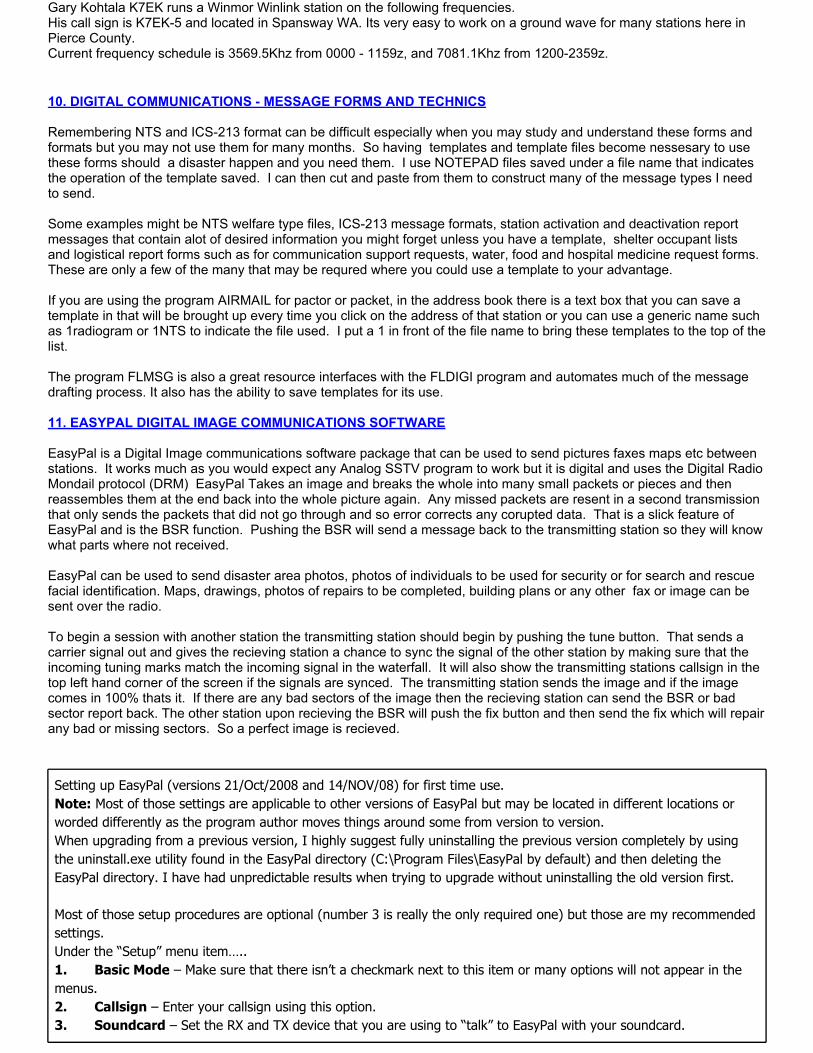
Gary Kohtala K7EK runs a Winmor Winlink station on the following frequencies.His call sign is K7EK-5 and located in Spansway WA. Its very easy to work on a ground wave for many stations here in Pierce County.Current frequency schedule is 3569.5Khz from 0000 - 1159z, and 7081.1Khz from 1200-2359z. 10. DIGITAL COMMUNICATIONS - MESSAGE FORMS AND TECHNICS Remembering NTS and ICS-213 format can be difficult especially when you may study and understand these forms and formats but you may not use them for many months. So having templates and template files become nessesary to use these forms should a disaster happen and you need them. I use NOTEPAD files saved under a file name that indicates the operation of the template saved. I can then cut and paste from them to construct many of the message types I need to send. Some examples might be NTS welfare type files, ICS-213 message formats, station activation and deactivation report messages that contain alot of desired information you might forget unless you have a template, shelter occupant lists and logistical report forms such as for communication support requests, water, food and hospital medicine request forms. These are only a few of the many that may be requred where you could use a template to your advantage. If you are using the program AIRMAIL for pactor or packet, in the address book there is a text box that you can save a template in that will be brought up every time you click on the address of that station or you can use a generic name such as 1radiogram or 1NTS to indicate the file used. I put a 1 in front of the file name to bring these templates to the top of the list. The program FLMSG is also a great resource interfaces with the FLDIGI program and automates much of the message drafting process. It also has the ability to save templates for its use. 11. EASYPAL DIGITAL IMAGE COMMUNICATIONS SOFTWARE EasyPal is a Digital Image communications software package that can be used to send pictures faxes maps etc between stations. It works much as you would expect any Analog SSTV program to work but it is digital and uses the Digital Radio Mondail protocol (DRM) EasyPal Takes an image and breaks the whole into many small packets or pieces and then reassembles them at the end back into the whole picture again. Any missed packets are resent in a second transmission that only sends the packets that did not go through and so error corrects any corupted data. That is a slick feature of EasyPal and is the BSR function. Pushing the BSR will send a message back to the transmitting station so they will know what parts where not received. EasyPal can be used to send disaster area photos, photos of individuals to be used for security or for search and rescue facial identification. Maps, drawings, photos of repairs to be completed, building plans or any other fax or image can be sent over the radio. To begin a session with another station the transmitting station should begin by pushing the tune button. That sends a carrier signal out and gives the recieving station a chance to sync the signal of the other station by making sure that the incoming tuning marks match the incoming signal in the waterfall. It will also show the transmitting stations callsign in the top left hand corner of the screen if the signals are synced. The transmitting station sends the image and if the image comes in 100% thats it. If there are any bad sectors of the image then the recieving station can send the BSR or bad sector report back. The other station upon recieving the BSR will push the fix button and then send the fix which will repair any bad or missing sectors. So a perfect image is recieved.
Setting up EasyPal (versions 21/Oct/2008 and 14/NOV/08) for first time use.Note: Most of those settings are applicable to other versions of EasyPal but may be located in different locations or worded differently as the program author moves things around some from version to version.When upgrading from a previous version, I highly suggest fully uninstalling the previous version completely by using the uninstall.exe utility found in the EasyPal directory (C:\Program Files\EasyPal by default) and then deleting the EasyPal directory. I have had unpredictable results when trying to upgrade without uninstalling the old version first. Most of those setup procedures are optional (number 3 is really the only required one) but those are my recommended settings.Under the “Setup” menu item…..1. Basic Mode – Make sure that there isn’t a checkmark next to this item or many options will not appear in the menus.2. Callsign – Enter your callsign using this option.3. Soundcard – Set the RX and TX device that you are using to “talk” to EasyPal with your soundcard.
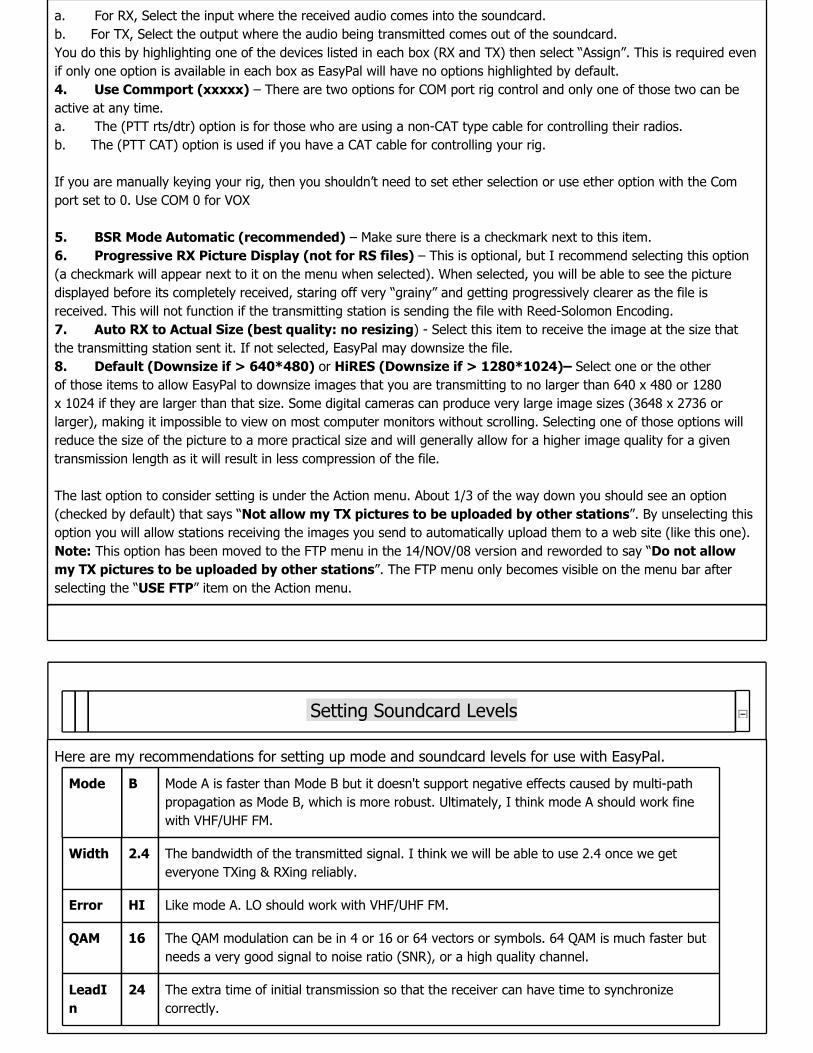
a. For RX, Select the input where the received audio comes into the soundcard.b. For TX, Select the output where the audio being transmitted comes out of the soundcard.You do this by highlighting one of the devices listed in each box (RX and TX) then select “Assign”. This is required even if only one option is available in each box as EasyPal will have no options highlighted by default.4. Use Commport (xxxxx) – There are two options for COM port rig control and only one of those two can be active at any time.a. The (PTT rts/dtr) option is for those who are using a non-CAT type cable for controlling their radios.b. The (PTT CAT) option is used if you have a CAT cable for controlling your rig. If you are manually keying your rig, then you shouldn’t need to set ether selection or use ether option with the Com port set to 0. Use COM 0 for VOX 5. BSR Mode Automatic (recommended) – Make sure there is a checkmark next to this item.6. Progressive RX Picture Display (not for RS files) – This is optional, but I recommend selecting this option (a checkmark will appear next to it on the menu when selected). When selected, you will be able to see the picture displayed before its completely received, staring off very “grainy” and getting progressively clearer as the file is received. This will not function if the transmitting station is sending the file with Reed-Solomon Encoding.7. Auto RX to Actual Size (best quality: no resizing) - Select this item to receive the image at the size that the transmitting station sent it. If not selected, EasyPal may downsize the file.8. Default (Downsize if > 640*480) or HiRES (Downsize if > 1280*1024)– Select one or the other of those items to allow EasyPal to downsize images that you are transmitting to no larger than 640 x 480 or 1280 x 1024 if they are larger than that size. Some digital cameras can produce very large image sizes (3648 x 2736 or larger), making it impossible to view on most computer monitors without scrolling. Selecting one of those options will reduce the size of the picture to a more practical size and will generally allow for a higher image quality for a given transmission length as it will result in less compression of the file. The last option to consider setting is under the Action menu. About 1/3 of the way down you should see an option (checked by default) that says “Not allow my TX pictures to be uploaded by other stations”. By unselecting this option you will allow stations receiving the images you send to automatically upload them to a web site (like this one).Note: This option has been moved to the FTP menu in the 14/NOV/08 version and reworded to say “Do not allow my TX pictures to be uploaded by other stations”. The FTP menu only becomes visible on the menu bar after selecting the “USE FTP” item on the Action menu.
Setting Soundcard Levels
Here are my recommendations for setting up mode and soundcard levels for use with EasyPal.
Mode B Mode A is faster than Mode B but it doesn't support negative effects caused by multi-path propagation as Mode B, which is more robust. Ultimately, I think mode A should work fine with VHF/UHF FM.
Width 2.4 The bandwidth of the transmitted signal. I think we will be able to use 2.4 once we get everyone TXing & RXing reliably.
Error HI Like mode A. LO should work with VHF/UHF FM.
QAM 16 The QAM modulation can be in 4 or 16 or 64 vectors or symbols. 64 QAM is much faster but needs a very good signal to noise ratio (SNR), or a high quality channel.
LeadIn
24 The extra time of initial transmission so that the receiver can have time to synchronize correctly.
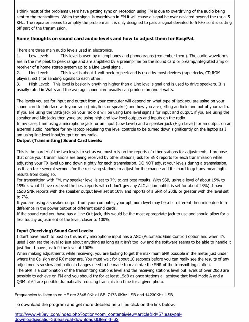
I think most of the problems users have getting sync on reception using FM is due to overdriving of the audio being sent to the transmitters. When the signal is overdriven in FM it will cause a signal be over deviated beyond the usual 5 KHz. The repeater seems to amplify the problem as it is only designed to pass a signal deviated to 5 KHz so it is cutting off part of the transmission.
Some thoughts on sound card audio levels and how to adjust them for EasyPal. There are three main audio levels used in electronics.1. Low Level: This level is used by microphones and phonographs (remember them). The audio waveforms are in the mV peek to peek range and are amplified by a preamplifier on the sound card or preamp/integrated amp or receiver of a home stereo system up to a Line Level signal.2. Line Level: This level is about 1 volt peek to peek and is used by most devices (tape decks, CD ROM players, ect.) for sending signals to each other.3. High Level: This level is basically anything higher than a Line level signal and is used to drive speakers. It is usually rated in Watts and the average sound card usually can produce around 4 watts. The levels you set for input and output from your computer will depend on what type of jack you are using on your sound card to interface with your radio (mic, line, or speaker) and how you are getting audio in and out of your radio. If you are using the Data jack on your radio it will be using Line level signals for input and output, if you are using the speaker and Mic jacks then youe are using high and low level outputs and inputs on the radio.In my case, I am using a microphone jack for an input (Low Level) and a speaker jack (High Level) for an output on an external audio interface for my laptop requiering the level controls to be turned down significantly on the laptop as I am using line level input/output on my radio.Output (Transmitting) Sound Card Levels: This is the harder of the two levels to set as we must rely on the reports of other stations for adjustments. I propose that once your transmissions are being received by other stations; ask for SNR reports for each transmission while adjusting your TX level up and down slightly for each transmission. DO NOT adjust your levels during a transmission, as it can take several seconds for the receiving stations to adjust for the change and it is hard to get any meaningful results from doing so.For transmitting with FM, my speaker level is set to 7% to get best results. With SSB, using a level of about 15% to 19% is what I have recieved the best reports with (I don't gey any ALC action until it is set for about 23%). I have 15dB SNR reports with the speaker output level set at 10% and reports of a SNR of 20dB or greater with the level set to 7%. If you are using a speaker output from your computer, your optimum level may be a bit different then mine due to a difference in the power output of different sound cards.If the sound card you have has a Line Out jack, this would be the most appropriate jack to use and should allow for a less touchy adjustment of the level, closer to 100%. Input (Receiving) Sound Card Levels: I don’t have much to post on this as my microphone input has a AGC (Automatic Gain Control) option and when it's used I can set the level to just about anything as long as it isn’t too low and the software seems to be able to handle it just fine. I have just left the level at 100%.When making adjustments while receiving, you are looking to get the maximum SNR possible in the meter just under where the Callsign and RX meter are. You must wait for about 10 seconds before you can really see the results of any adjustments so slow and patient changes need to be made to maximize the SNR of the transmitting station.The SNR is a combination of the transmitting stations level and the receiving stations level but levels of over 20dB are possible to achieve on FM and you should try for at least 15dB as once stations all achieve that level Mode A and a QRM of 64 are possible dramatically reducing transmission time for a given photo.
Frequencies to listen to on HF are 3845.0Khz LSB, 7173.0Khz LSB and 14230Khz USB. To download the program and get more detailed help files click on the link below: http://www.vk3evl.com/index.php?option=com_content&view=article&id=57:easypal-downloads&catid=36:easypal-downloads&Itemid=62

Companion program to EasyPal is SstvPics for sorting and keeping your images.It contains a particular program called I-view32 that is very useful.Download it at the following link: http://w3wvg.com/31243.html GLOSSARY OF PACKET AND DIGITAL TERMS