DIGITAL ANNUNCIATOR INSTALLATION INSTRUCTIONS DD-40NTS … · 2011-09-15 · DIGITAL ANNUNCIATOR...
30
-1- DIGITAL ANNUNCIATOR INSTALLATION INSTRUCTIONS DD-40NTS-O, DD-40NTS-U DD-NTS II 5-02 WARNING: READ THESE INSTRUCTIONS CAREFULLY BEFORE INSTALLING OR OPERATING THE DD ANNUNCIATOR SYSTEM. AN IMPROPERLY INSTALLED OR OPERATING DEVICE MAY RESULT IN AN UNSAFE OPERATING CONDITION OF THE MONITORED MACHINE WHICH CONSEQUENTLY COULD POSE THE THREAT OF PERSONAL INJURY TO OPERATORS OR OTHER NEARBY PERSONNEL. 1.0 DESCRIPTION 1.1 The Altronic DD-40NTS digital annunciator is an electronic, 40-point monitor and shutdown device. The annunciator has a built-in hourmeter / tachometer with over speed protection. A front mounted keypad serves as a user interface along with a LCD display. 1.2 The DD-40NTS annunciator system is suitable for use in Class I, Group C or D, Division 2 hazardous locations and consists of the following items: DD-40NTS-O Annunciator, 40 normally open points DD-40NTS-U Annunciator, 40 normally closed or open points (can be mixed) (requires terminal module part no. 672169-1) 691200-1 Power Supply - 10 to 30 Vdc, 50 mA max. or 100 to 400 volt negative ground CD ignition systems. 693115-1 Cable, DB-25 (2 required for DD-40NTS-U unit only) 693116-1 Cable, DB-9 (for RS-232 serial communications) 1.3 RS-232 / RS-485 serial communications are provided for remote engine monitoring via modem or satellite. Serial communications require the use of the DC power option. 1.4 For reliable operation, the following instructions must be adhered to strictly. 2.0 MOUNTING 2.1 ANNUNCIATOR UNIT - Using four #10 screws, mount the Annunciator Unit inside a control panel or to a suitable flat surface so that the display is at a convenient viewing height. A drilling template is provided. The annunciator unit box must be grounded. NOTE: Avoid mounting with the LCD display facing direct sunlight. The display temperature range is -40°F. to +175°F. 2.2 691200-1 POWER SUPPLY - The Power Supply mounts directly to the back of the Annunciator Unit using two 8-32 x 5/16" length screws provided. 2.3 The terminal strip board (only applicable on the -U version) can be snapped on 32 or 35 mm DIN mounting rails.
Transcript of DIGITAL ANNUNCIATOR INSTALLATION INSTRUCTIONS DD-40NTS … · 2011-09-15 · DIGITAL ANNUNCIATOR...

-1-
DIGITAL ANNUNCIATOR INSTALLATION INSTRUCTIONSDD-40NTS-O, DD-40NTS-U DD-NTS II 5-02
WARNING: READ THESE INSTRUCTIONS CAREFULLY BEFORE INSTALLING OROPERATING THE DD ANNUNCIATOR SYSTEM. AN IMPROPERLY INSTALLED OROPERATING DEVICE MAY RESULT IN AN UNSAFE OPERATING CONDITION OF THEMONITORED MACHINE WHICH CONSEQUENTLY COULD POSE THE THREAT OFPERSONAL INJURY TO OPERATORS OR OTHER NEARBY PERSONNEL.
1.0 DESCRIPTION
1.1 The Altronic DD-40NTS digital annunciator is an electronic, 40-point monitor and shutdowndevice. The annunciator has a built-in hourmeter / tachometer with over speed protection.A front mounted keypad serves as a user interface along with a LCD display.
1.2 The DD-40NTS annunciator system is suitable for use in Class I, Group C or D, Division 2hazardous locations and consists of the following items:
DD-40NTS-O Annunciator, 40 normally open pointsDD-40NTS-U Annunciator, 40 normally closed or open points (can be mixed)
(requires terminal module part no. 672169-1)
691200-1 Power Supply - 10 to 30 Vdc, 50 mA max. or 100 to 400 volt negative groundCD ignition systems.
693115-1 Cable, DB-25 (2 required for DD-40NTS-U unit only) 693116-1 Cable, DB-9 (for RS-232 serial communications)
1.3 RS-232 / RS-485 serial communications are provided for remote engine monitoring viamodem or satellite. Serial communications require the use of the DC power option.
1.4 For reliable operation, the following instructions must be adhered to strictly.
2.0 MOUNTING
2.1 ANNUNCIATOR UNIT - Using four #10 screws, mount the Annunciator Unit inside a controlpanel or to a suitable flat surface so that the display is at a convenient viewing height. Adrilling template is provided. The annunciator unit box must be grounded.
NOTE: Avoid mounting with the LCD display facing direct sunlight. The displaytemperature range is -40°F. to +175°F.
2.2 691200-1 POWER SUPPLY - The Power Supply mounts directly to the back of theAnnunciator Unit using two 8-32 x 5/16" length screws provided.
2.3 The terminal strip board (only applicable on the -U version) can be snapped on 32 or 35 mmDIN mounting rails.

-2-
3.0 WIRING (SEE WIRING DIAGRAMS)
3.1 The annunciator unit plugs into the power supply through a DB-9 connector.
3.2 The sensor leads connect to the removable terminal strips on the back of the annunciator.These terminal strips match those used with the earlier DD-40NT / DD-20NT systems.
3.3 At the terminal strip of the Annunciator unit, strip the insulation back 3/8"; twist the exposedwires tightly together. Insert the exposed wire end completely into the terminal strip andsecurely tighten the clamping screw. It is suggested that wire 18 AWG (max.) to 24 AWG (min.) be used for the connections directly to the annunciator terminal strip connector.
3.4 Wires running to the various sensors should be in good condition or replaced with new wiring.Terminations to the main panel terminal strip (if used) should be made with a suitable terminaland crimping tool or by soldering. There is no requirement for explosion-proof conduit orClass I enclosures; however, suitable physical protection should be provided.
CAUTION:a.) SENSOR WIRING: Sensor wires within the panel enclosure must be kept at least two
(2) inches from other wiring. Use a separate junction box for ignition and fuel valvewires. Run sensor leads leaving the panel in a conduit separate from all other wiring andkeep separate throughout the installation. Wiring to the sensors must have a grade ofinsulation capable of withstanding an AC voltage of 500 V. RMS. Sensor leads may beconnected to any passive device using contacts such as standard switch gauges or levelswitches. DO NOT connect sensor leads to relay contacts or to any voltage producingelement.
b.) Sensors will be exposed to much lower voltages and current than with the standardMurphy tattletale or similar type system. In the case of a field conversion where sensorshave previously been used with Murphy tattletales, it is recommended that the sensorsbe checked frequently when the DD system is first put into use. Sensor contacts maybe burned or pitted from past exposure to ignition system primary voltage. It is advisableto replace such sensors.
c.) If it becomes necessary to check sensor to panel wiring with an ohmmeter or otherchecker, first DISCONNECT the plug-in terminal strips from the back of the AnnunciatorUnit. Applying voltage to the annunciator through the sensor leads may damage thedevice. In addition, the area should be tested as non-hazardous before such testingcommences.
3.5 For the -U version, connect the annunciator unit to the 672169-1 terminal modules using693115-x cables with standard DB-25 connectors. Make sure the cables are securelyconnected.
WARNING REGARDING OLDER ALTRONIC OVERSPEED DEVICES:
If retrofitting into an older panel, the DD-40NTS annunciator will not recognize the outputsignal from older Altronic overspeed devices:
DTO-1000, DTO-1010, DTO-2200, DTO-3200
DTHO-2100, DO-3300, PTO-2100, PTHO-2100
These devices will NOT work for overspeed protection in conjunction with a DD-40NTSannunciator. For such protection, use the overspeed feature built into the DD-40NTSannunciator (refer to section 6.3).

-3-
4.0 ANNUNCIATOR CONFIGURATION
4.1 The DD-40NTS series unit MUST be configured prior to use. If replacing an older series DDseries annunciator, modes 1 and 4 can be used to directly emulate the older system’sperformance. Mode 1 duplicates the operation of the DD-40 series and mode 4 duplicatesthe DD-20 series units. To configure the unit, press the MENU key to reach the configurationheadings from the normal display mode. After a selection has been made, press the ENTERkey to save the selection. Press MENU to move to the next step. A flowchart is provided thatshows step-by-step progression through the annunciator configuration procedure.
4.2 CONFIGURE MODE - The mode selection allows the unit to be programmed in one of fourmodes as shown. The RESET button must be pressed after a change in mode number.
NOTE: A keypad sequence (password) is required to edit values. From the status screen(RPM, HOURS, or STATUS) , press and hold down the ENTER key then press the MENU keyat the same time to allow values to be modified. Otherwise, selected items may only beviewed. There is no similar protection for the TIMER button (Class B1 and B2 timers) orhourmeter.
MODE TYPE OF POINTS CHANNELS NOTES
124 Class A
16 Class B1
30-37, 40-47, 50-57
10-17, 20-27
Duplicates operation
of DD-40NT series.
2
24 Class A
12 Class B1
4 Class B2
30-37, 40-47, 50-57
10-17, 20-23
24-27
3
24 Class A
10 Class B1
2 Class B2
4 Class C
30-37, 40-47, 50-57
10-17, 20-21
22-23
24-27
412 Class A
8 Class B1
20-27, 30-32, 40
10-17
Duplicates operation
of DD-20NT series.
Class Definitions:Class A Point is always armed.Class B1 Point is armed B1 time after power-up or pressing the RESET key.Class B2 Point is armed B2 time after power-up or pressing the RESET key.Class C Point is armed after it clears.
Use the UP and DOWN keys to select the mode and press the ENTER key to save the mode.
4.3 PROGRAM RPM 1 - This selects the RPM pre-divide number equal to the pulses perrevolution (PPR). The RPM signal can be from either a CD ignition shutdown lead or amagnetic pickup. The range is selectable from 0.5 to 360 PPR. Use the UP and DOWN keysto select the proper pre-divide number and press the ENTER key to save.

-4-
4.4 PROGRAM RPM 2 - This selects the RPM overspeed value. The range is selectable from1 to 2499 RPM. Use the UP and DOWN keys to select the overspeed value and pressthe ENTER key to save the selection. To disable the overspeed function, enter 2500.
4.5 PROGRAM TIMER 2 - This selects the time delay in seconds for tripping SDI and OUTPUT2 after a fault occurs. The range of the delay is from 1 to 60 seconds. Use the UP andDOWN keys to select the time and press the ENTER key to save the selection. In typicalapplications, SW 1 is used to turn off the fuel and either SDI or SW2 is used to turn off theignition.
4.6 PROGRAM SW1 - This selects the RUN state of output SW1, normally open (N.O.) ornormally closed (N.C.). Use the UP and DOWN keys to select the state and press ENTERto save.
4.7 PROGRAM SW2 - This selects the RUN state of output SW2, normally open (N.O.) ornormally closed (N.C.). Use the UP and DOWN keys to select the state and press ENTERto save.
4.8 PROGRAM SERIAL MODE - This selects the type of communications used by theannunciator. Selections are provided for NONE (must be used for ignition poweredapplications), RS-232 ASCII (A 232), RS-232 Modbus RTU (232), RS-485 ASCII (A 485), orRS-485 Modbus RTU (485). Use the UP and DOWN keys to select and ENTER to save.
4.9 PROGRAM NODE NUMBER - This selects the node number for the annunciator. The rangeof the node number is from 01 to 99. Use the UP and DOWN keys to select the node numberand press the ENTER key to save the selection. This applies only for serial communicationsand need not be programmed for non-serial applications.
4.10 PROGRAM HOURS - This selects the pre-programmed number of hours. The range is from00000 to 65535 hours. Press the UP and DOWN arrow keys to modify the hours, then pressthe ENTER key to save.
4.11 TIMER KEY - This selects the B1 and B2 timer delays. The range is from 1 to 999 seconds.Pressing the TIMER key once displays the B1 timer, and pressing the TIMER key againdisplays the B2 timer. Use the UP and DOWN keys to change the respective B timer andpress the ENTER key to save the selection.
4.12 DEFAULT SETTINGS - As shipped from the factory, the device default settings are asfollows:
MODE 1RPM1 (PPR) 1RPM2 200 RPMTIMER2 5 secondsSW1 N.O.SW2 N.O.SERIAL MODE NoneNODE NUMBER 01HOURS 00000B1 TIMER 5 secondsB2 TIMER 10 seconds
NOTE: Unit must be properly configured for each application prior to use.

-5-
5.0 KEYPAD DESCRIPTION / FUNCTION
5.1 MENU - This key allows the user to view / change the following:1. Mode selection2. Pulses per revolution3. Over speed value4. Output timer 25. Node number6. Programmed hours
5.2 UP ARROW - This key is used to increment / modify selections and allows the user to vieweither the current RPM, the hourmeter or the annunciator status.
5.3 DOWN ARROW - This key is used to decrement / modify selections and allows the user toview either the current RPM , the hourmeter or the annunciator status.
5.4 ENTER - This key allows for selected items to be saved.
5.5 STOP - This key initiates a shutdown condition and the unit will display a status of [60]. Thishas precedence over all other functions.
5.6 RESET - This key clears any faults and resets the Class B1 and B2 timers. The annunciatordisplays [00] if one or more points is not armed. Once all the channels are armed, the displayreads [01]. The annunciator will power up in the RESET mode. The unit will not reset theoutputs if any of the Class A points are faulted.
5.7 TEST - This key provides for battery and operating voltage tests and also allows inputs to betested (faulted) without causing a shutdown. The battery in the Power Supply may bechecked when the machine is down and the display reads [00]; push and hold the TEST key -a reading of [80] indicates satisfactory battery voltage. The operating voltage may bechecked when the machine is operating and the display reads [01]; push and hold the TESTkey - a reading of [89] indicates the operating voltage is acceptable. To test the sensor inputpoints, the annunciator must first be displaying [01] meaning all points are armed. Push andrelease the TEST key, and the display will read [09] indicating the Test Mode. Faulted pointswill be displayed but will not cause the outputs to trip. Testing an additional point requires theTEST button to be pressed again. The annunciator will remain in test mode for two minutesbefore reverting back to the running mode [01]. Any point not cleared in two minutes (eitherby pressing the TEST or RESET key) will cause the outputs to trip.
NOTE: Two fault occurrences will override the TEST mode: manual STOP function [60] andOVERSPEED [70].
5.8 TIMER - This key allows the B1 and B2 delay timers to be viewed or modified.
5.9 KEYPAD SEQUENCE (PASSWORD) PROTECTION - From the status screen (RPM,HOURS, or STATUS) , press and hold the ENTER key, then press the MENU key to allowvalues to be modified. Otherwise, the selected items may only be viewed. There is nokeypad sequence protection for the TIMER button (Class B1 and B2 timers).
5.10 CANCEL TIMERS - From the status screen (RPM, HOURS, or STATUS), depress theENTER key. While holding the ENTER key, also press the DOWN ARROW key.

-6-
6.0 OPERATION
6.1 OPERATING SEQUENCE
MACHINE DISPLAY FUNCTION DESCRIPTION
Down [10-57] Shutdown Shutdown caused by the fault number indicated. Number
will remain until fault is corrected and RESET button
depressed.
[60] Shutdown Shutdown caused by depressing STOP button.
[70] Shutdown Shutdown caused by overspeed.
[71] Shutdown Shutdown caused by loss of RPM signal.
[80] Shutdown Push TEST button when down, indicates battery is OK.
[00] Reset Before starting machine, momentarily push the RESET
button. A display of [00] indicates all Class A sensors are
ready for start-up. Any number 10-57 indicates a faulted
sensor that must be cleared before start-up.
[60] Engine
Purge
To purge engine prior to start, depress the STOP button,
roll the engine to purge, then push the RESET button.
Engine can then be started provided display reads [00].
Running [00] Start-up Start-up tim ers have Class B1 and B2 points disarmed. All
Class A points are being monitored. Pushing the RESET
button re-cycles the start-up timers. To cancel the start-up
timers, press the ENTER key, followed by the DOW N key
while still depressing the ENTER key.
[01] Normal All points are being monitored. The transition from [00] to
[01] indicates the end of the last s tart-up tim er interval.
[89] Test From [01] display, press and hold TEST button; indicates
adequate operating voltage.
[09] Test Press and release TEST button - a tim ed test period is
initiated for approximately two minutes. As a sensor is
faulted, its number is latched on the display (but the output
is not activated). To move to the next point, first clear the
sensor, then push the TEST button again. The display
reverts to [09] until the next sensor is faulted. After the last
test, push the TEST button to get [09] on the display; wait
two minutes until [01] displays.
[01] Normal Test period has ended; all points are being monitored. DO
NOT LEAVE M ACHINE UNLESS DISPLAY READS [01].
NOTE:
a.) TEST cannot be used until the start-up tim er interval ends - [01] on the display.
b.) A display reading of [09] means the system output will not activate unless the STOP button is
pushed.
c.) Do not leave a sensor number on the display after the last test; push the TEST button to get [09]
on the display; then wait two minutes until [01] displays or select the CANCEL TIMERS feature.
d.) For a complete system test, allow the test timer interval to expire - display changes from [09] to
[01]. Then cause one sensor to fault and allow the system output to activate. This will test the
entire system for correct operation upon a fault with minimal downtime.

-7-
6.2 RPM / HOURMETER - Press the UP and DOWN keys to view the RPM and the hourmeter.The RPM screen remains until the operator chooses another option. The Hours display willrevert to the status screen after two minutes. In either case, the annunciator will display thefault number when a shutdown occurs.
6.3 RPM OVERSPEED PROTECTION - The DD-40NTS annunciator has a built in tachometerto monitor engine overspeed. When the detected RPM is greater than the RPM overspeedsetpoint, the annunciator will trip the fuel and ignition outputs. When this occurs, the unit willdisplay [70] and activate the “FAULT” indicator. Refer to the Wiring Diagram - TachometerInput drawings for the proper hookup.
WARNING: The DD-40NTS annunciator will not recognize the output signal from an AltronicDTO-3200 or other older overspeed devices (see listing on page 2). These devices will NOTwork for overspeed protection in conjunction with a DD-40NTS annunciator. For suchprotection, use the overspeed feature built into the DD-40NTS annunciator.
6.4 BATTERY - The 691200-1 Power Supply contains a special long-life lithium battery. Whenthe monitored equipment is not operating, current draw form the battery is only microamps(millionths of amps). When the annunciator is powered, there is no drain from the battery.This allows for a battery life of up to 5 years in normal operation. The battery in the powersupply is replaceable; use ONLY Altronic part no. 601952. Be sure to observe the properpolarity as marked in the Power Supply when replacing the battery.
7.0 OUTPUTS
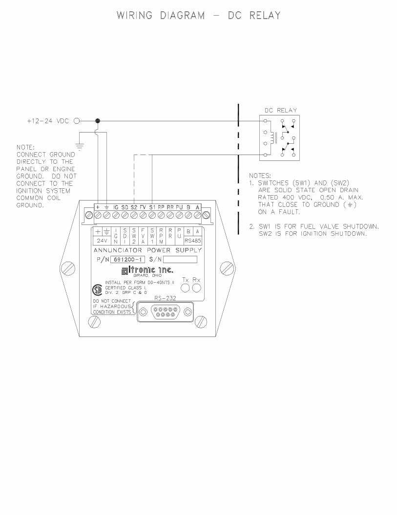
7.1 Two (2) digital outputs SW1 and SW2 are located in the Power Supply. These are rated 400volts DC, 0.5 amp maximum.
7.2 Output SW1 will trip immediately upon a fault condition or if the STOP key is depressed.
7.3 Outputs SDI and SW2 will trip after a pre-programmed time delay (TIMER PROGM2) fromeither a fault condition or if the STOP key is depressed.
7.4 For Power Supply 691200-1, the maximum voltage is 400 volts from a negative ground C.D.ignition with a current drain of microamps. The maximum current rating is 50 mA whenpowered from a DC voltage source of 10 to 30 volts.
8.0 SERIAL COMMUNICATIONS
8.1 Serial communications may be selected as RS-232 or RS-485 using ASCII or Modbus RTUprotocol.
8.2 MASTER/SLAVE OPERATION - The RS-485 communication system in the annunciator isdesigned as a master/slave system; that is, each unit responds to its own unique address(node number) only after it is interrogated by the master (computer). A simple command /response protocol must be strictly observed.
8.3 NODE NUMBER - The node number is used in the system to identify the desired slave unitbeing polled. The node number can be any numeric value from 1 to 99.

-8-
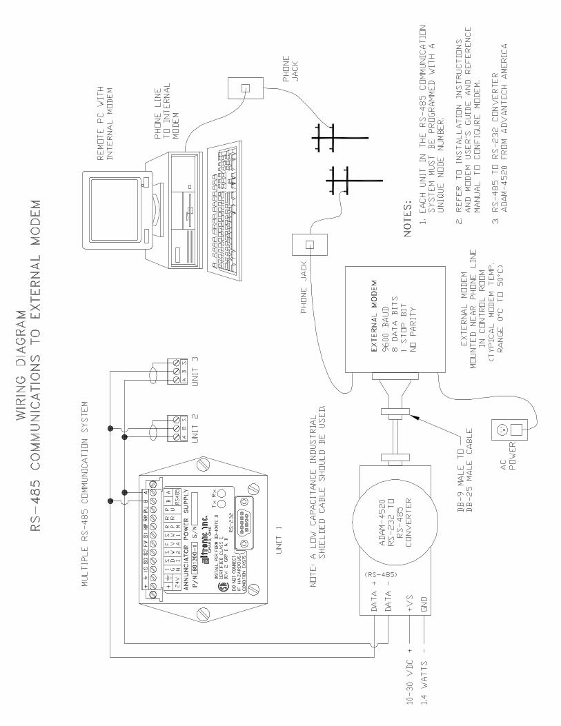
8.4 ASCII COMMUNICATION - All communication to and from the annunciator is performed usingASCII characters. This allows the information to be processed with the "string" functionscommon to high level computer languages such as BASIC and C. For computers that supportstandard serial port interfaces, no special machine language software drivers are required.The use of the ASCII format also allows for the connection of these devices to an auto answermodem for long distance operation without the need for a local supervisory computer. TheASCII characters also make system debugging easy using standard terminal emulationsoftware.
8.5 COMMUNICATIONS PARAMETERSBaud Rate: 9600 Data Bits: 8 Stop Bits: 1 Parity: None
8.6 COMMAND STRUCTURE - The annunciator operates with a simple command/responseprotocol to monitor all functions. A command must be transmitted to the unit by the master(computer or PLC) before the slave can respond with useful data. A slave unit can neverinitiate a communications sequence.
Communication to the annunciator is performed with two character ASCII command codes.The general format used for the commands is illustrated below using the READ DATAcommand as an example. The hexadecimal values for the characters are shown only as areference for those using low level (assembly language) decoding and will not appear on thecommunications terminal screen. All of the characters used in the communications protocolare standard ASCII characters and appear on the computer keyboard as shown with theexception of the "not acknowledge" (NAK) which is the industry standard "control U".
header start node space command end
ASCII > ( 01 R D )
HEX 3Eh 28h 30h 31h 20h 52h 44h 29h
Command Header ">" (3Eh) - Each command must begin with the command headersometimes referred to as a prompt character. The ASCII character used is the ">" whichmeans that a command message will be sent from the master to the slave.
Start of Text "(" (28h) - The command header must be followed by the start of text indicator.
Node Number "01 -99" (30h 31h) - The node number or address of the device beingcontacted.
Space (20h) - Following the node number is an ASCII space character (not printable, value20h) to act as a delimiter between the node number and the two character command word.
Command Word "RD" (52h, 44h) - The command words are standard two letter (upper case)commands sent by the master for gathering specific information about the status of a slave.The commands are listed under STANDARD COMMANDS below.
End of Text ")" (29h) - The end of text indicator says this is the end of the command.

-9-
STANDARD COMMANDS
Information coming
serial command(s) Command Response Notes
Annunciator status >(01 RD) <(01 XX) (XX - Refer to section 6.0)
Read hourmeter >(01 RH) <(01 XXXXX) (XXXXX = Hours)
Read current RPM >(01 RP) <(01 XXXX) (XXXX = RPM)
Reset the annunciator >(01 RR) <(01 RR)
Stop the annunciator >(01 RS) <(01 RS)
Valid Response - A command/response sequence is not complete until a valid response isreceived. When a slave unit receives a valid command, it interprets the command, performsthe desired function and then communicates the response to the master within 20mS. Themaster may not initiate a new command until the response from a previous command iscompleted.
A valid response can occur in three ways:1. A normal response indicated by a "< " header and "( )" beginning and end of text.2. An error response indicated by a "§" NAK (not acknowledged) .3. A communications time-out error.
An NAK error response will be sent by the annunciator when it has received a command withan error in the message. All commands must be of the format above. The header,start-and-end of text characters, a valid node number and spaces must be sent and correctto receive an NAK; if not, no response will be sent.
8.7 RS-485 COMMUNICATIONS
A. HALF DUPLEX OPERATION - The RS-485 system employed uses two wires forcommunication and cannot send and receive data at the same time over the same twowires making it a half duplex system. When the master is in the transmit mode, theslave is in the receive mode and visa-versa.
B. ELECTRICAL OPERATING RANGE - RS-485 is a communications standard to satisfythe need for multi-dropped systems that can operate at high speeds over long distances.RS-485 uses a balanced differential pair of wires switching from 0 to 5 volts tocommunicate data. RS-485 drivers can handle common mode voltages from !7 to +12volts without loss of data, making them an excellent choice for industrial environments.
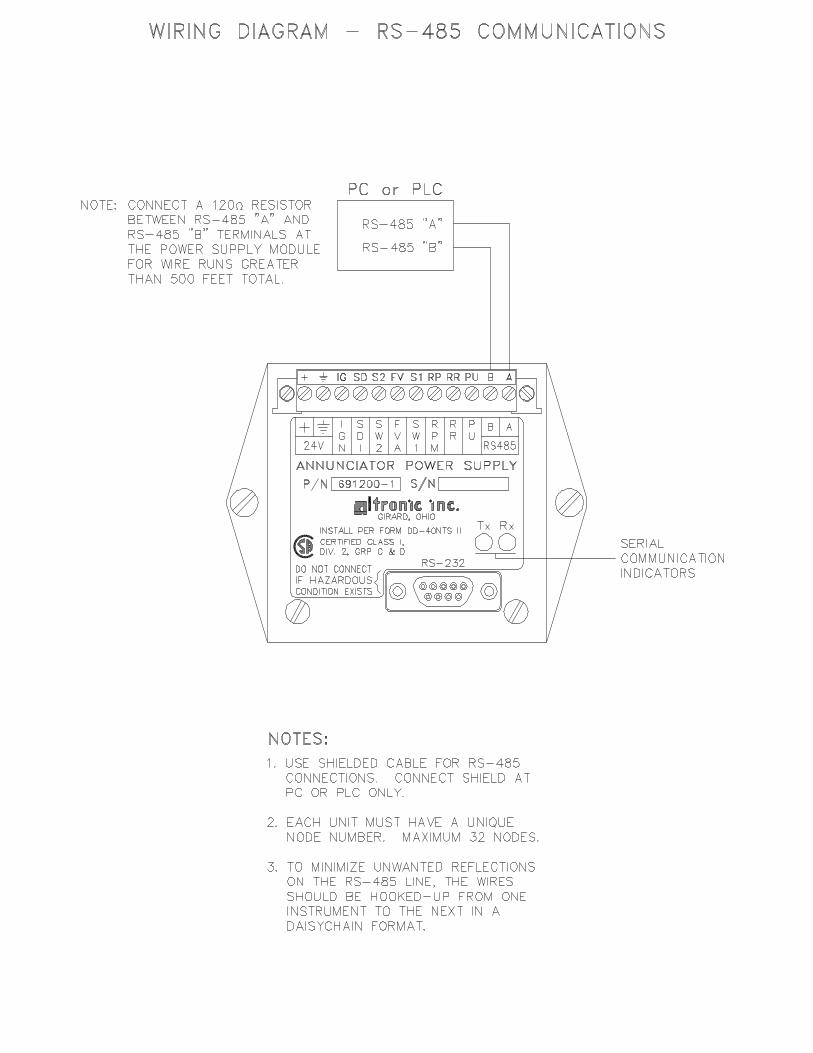
C. COMMUNICATIONS WIRING - The RS-485 wiring diagram illustrates the wiringrequired for multiple slave unit hookup. Note that every slave unit has a directconnection to the master. This allows any one slave unit to be removed from servicewithout affecting the operation of the other units. Every unit must be programmed witha unique address or node number, but the addition of new units or nodes can be in anyorder. To minimize unwanted reflections on the transmission line, the bus should bearranged as a trunk line going from one module to the next. Random structures of thetransmission line should be avoided. Special care must be taken with long busses (500feet or more) to ensure error free operation. Long busses must be terminated with a 120ohm resistor between the terminals marked RS-485 "A" and RS-485 "B" at the masteronly. The use of twisted pair shielded cable will enhance signal fidelity and isrecommended. To prevent ground loops the shield should be connected to the shieldterminal at the master only.

-10-
D. LOADING - RS-485 uses a balanced differential pair of wires switching from 0 to 5 voltsto communicate data. In situations where many units (99 max.) are connected togetheron a long run, voltage drop on the communications leads becomes a major problem.Voltage drops on the RS-485 minus lead appear as a common mode voltage to thereceivers. While the receivers are rated to a maximum voltage difference of +/! 7 volts,!7V to +12V, a practical system should not have a voltage difference exceeding +/! 3volts under normal conditions. The wire gauge used for the connections therefore limitsthe maximum number of units or the maximum length of wire between units in eachapplication. The following formula can be used as a guideline to select the appropriatewire gauge.
For 18 AWG wire No. of annunciator units = (4000) / (ft of wire used)For 20 AWG wire No. of annunciator units = (3600) / (ft of wire used)For 22 AWG wire No. of annunciator units = (2400) / (ft of wire used)
NOTE: The maximum number of units connected together in a system is 99.
8.8 RS-232 COMMUNICATIONSA. For proper operation, the wire length should not exceed 50 feet.B. Use standard DB-9 connector and computer cable, Altronic no. 693 116-x or equivalent.
8.9 MODBUS STRUCTURE - The annunciator can operate as a Modbus RTU slave. Acommand must be transmitted to the unit by the master (computer or PLC) before the slavecan respond with useful data. A slave unit can never initiate a communications sequence.
Select the Modbus communications option. See section 4.8. Communication to theannunciator can then be performed using standard Modbus RTU protocol. Multiple registerreads are supported, specify number of registers.
Register (16 bit binary register value)
40001 RPM ( 0-2500 )
40002 Hourmeter hours ( 0-65535 )
40003 Class B1 timer ( seconds )
40004 Shutdown Status ( 0 = OK, 1 = Fault )
40005 Output Status ( bit 0 = SW 1, bit 1 = SW 2, 1 = tripped, 0 = running )
40006 Input ( chan. 10-27; bit 0 = 10, bit 8 = 20, bit 15 = 27 )
40007 Input ( chan. 30-47; bit 0 = 30, bit 8 = 40, bit 15 = 47 )
40008 Input ( chan. 50-57; bit 0 = 50, bit 7 = 57, bit 8 = ovrspd, bit 9 = loss of spd)
Input OK = 1, Input Fault = 0; 40006, 40007, 40008 all FF for running OK.

-11-
DRAWINGS SECTION:
SALES DRAWING - DD-40NTS-O ANNUNCIATOR SYSTEM
SALES DRAWING - DD-40NTS-U ANNUNCIATOR SYSTEM
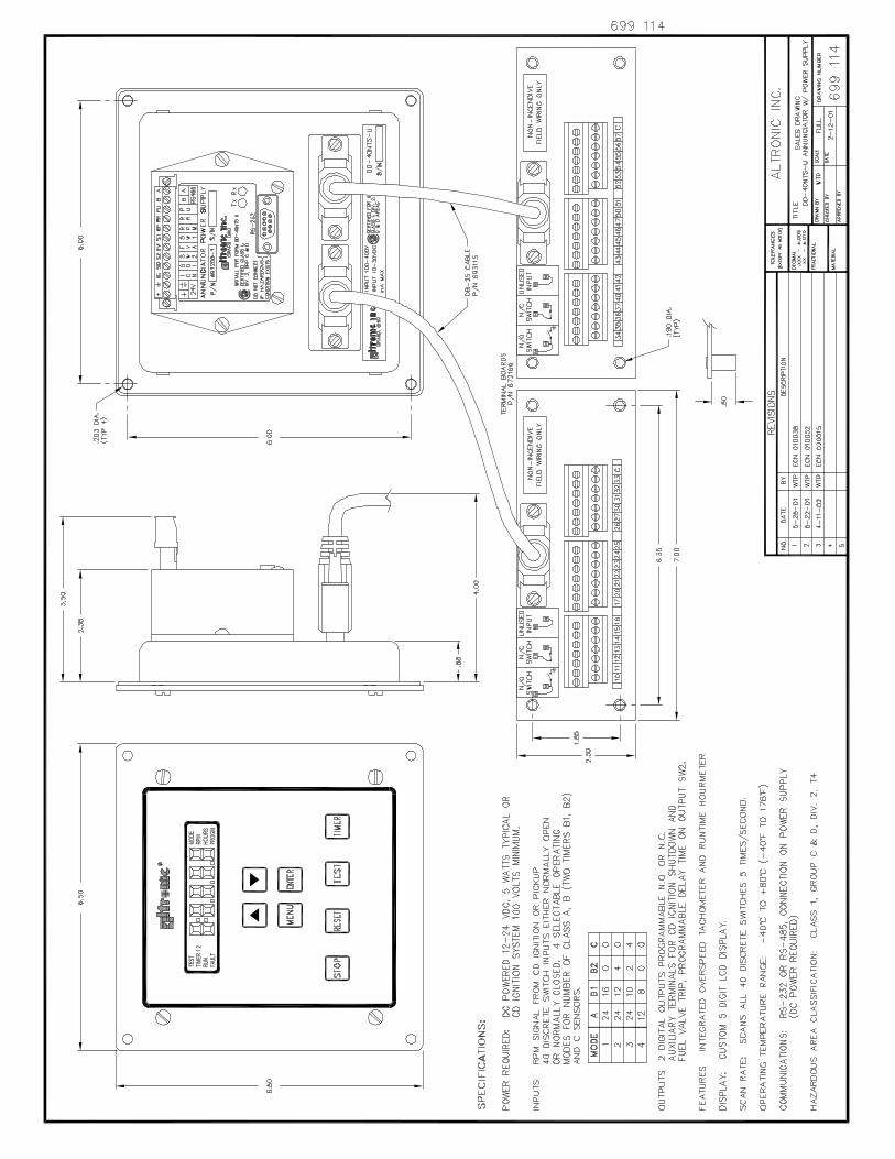
INSTALLATION DIAGRAM - DD-40NTS TO 691200-1 POWER SUPPLY
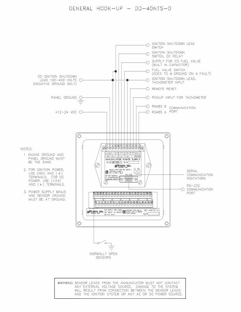
WIRING DIAGRAM - GENERAL HOOK-UP, DD-40NTS-O
WIRING DIAGRAM - GENERAL HOOK-UP, DD-40NTS-U
FLOWCHART - DD-40NTS
WIRING DIAGRAM - CD IGNITION AND CD FUEL VALVE (M50-CD)
WIRING DIAGRAM - DC POWERED FUEL VALVE (M50-B)
WIRING DIAGRAM - DC POWERED FUEL VALVE (M50-FS)
WIRING DIAGRAM - DC POWERED RELAY
WIRING DIAGRAM - TACHOMETER INPUT, IGNITION SHUTDOWN LEAD
WIRING DIAGRAM - TACHOMETER INPUT, PICKUP
WIRING DIAGRAM - REMOTE RESET
WIRING DIAGRAM - RS-485 COMMUNICATIONS
WIRING DIAGRAM - RS-232 COMMUNICATIONS
WIRING DIAGRAM - NULL MODEM CABLE
WIRING DIAGRAM - RS-485 COMMUNICATIONS TO EXTERNAL MODEM
WIRING DIAGRAM - RS-232 COMMUNICATIONS TO EXTERNAL MODEM


WIRING DIAGRAM: DC-POWERED AND CD FUEL VALVE
RS–232DO NOT CONNECTIF HAZARDOUSCONDITION EXISTS
Tx Rx
P/N 691200–1 S/N
GIRARD, OHIOINSTALL PER FORM DD-40NTV IICERTIFIED CLASS I,DIV 2, GRP C & D
ANNUNCIATOR POWER SUPPLY24V
IGN
B A
RS485
PU
RR
LUB
SW1
FVA
SW2
SDI
+ IG SD S2 FV S1 LB RR PU B A
3 8 MURPHY M50-CDREMOVE ALL JUMPERS. DO NOT GROUND #5 TERMINAL. CONNECTONLY TO COIL LEADS AS SHOWN.PNEUMATIC SYSTEM
690019SOLENOIDVALVE
ALTRONIC690040-1
AC/DC CONTROL
FUEL VALVE
FUEL VALVE
E C B D S
MURPHY221-PH-CD
IGNITIONSHUTDOWN
LEAD
12 – 24VDC
1 2
CAUTION: LUB TERMINAL (8TH FROM LEFT) REPLACES RPM TERMINAL ON THE 691200-1 POWER SUPPLY. IF REPLACING A 691200-1 POWER SUPPLY WITH 691200-3, REMOVE THE JUMPER BETWEEN THE 3RD AND 8TH (FROM LEFT) TERMINALS AND DIS-CARD. REFER TO INSTRUCTIONS DD-NTS II 5-02 FOR WIRING DETAILS USING A 691200-1 POWER SUPPLY.
NOTE: WHEN 24V IS USED TO POWER ANNUNCIATOR SUPPLY, THE SHUTDOWN LEAD MUST BE TIED TO THE “IGN” TERMINAL TO CHARGE THE TRIP CAPACITOR
NOTE: CONNECT GROUND DIRECTLY TO THE PANEL OR ENGINE. DO NOT CONNECT TO THE IGNITION SYSTEM COMMON COIL GROUND