
DIGEST OF RADIO
38
A MONTHLY DIGEST OF RADIO AND ALLIED MAINTENANCE MARCH 1942 '13^1,2-z 'o R3 mm'. ° MeS {.m reGep\ gs m and a v+e To S co' / ncluding a éprOduct`on AqGE sw,1cN {ea phOn°grap Ó cH ver °ers maovde {orsee page 24i THti rc,evera\ m°de\s p t,.. - RADIO - TELEVISION www.americanradiohistory.com
Transcript of DIGEST OF RADIO
A MONTHLY DIGEST OF RADIO AND ALLIED MAINTENANCE
MARCH 1942
'13^1,2-z
'o R3 mm'.
° MeS {.m reGep\ gs m and
a v+e To S
co' / ncluding a éprOduct`on
AqGE
sw,1cN {ea phOn°grap
Ó cH
ver °ers maovde {orsee page 24i
THti rc,evera\ m°de\s p
t,.. -
RADIO - TELEVISION www.americanradiohistory.com

You're "In The Service", Too
You radio service engineers may not be in uni- form, but you've got a big job in helping main- tain the home front. It is up to you to keep receiving sets in operation, no matter what shortages and restrictions may grow out of wartime needs.
Mallory knows what an enormous job the home front involves, and you may depend on Mallory and Mallory Distributors for help with that job. Mallory Approved Precision Products put quality parts at your disposal for efficient, eco- nomical replacements. They give you the benefit of the. Mallory time proven standardization program, tremendously important now that inventories are so short.
Furthermore, Mallory engineers are putting their backs into the task of overcoming the handicaps imposed by material shortages and wartime demands.They have set out to keep you supplied with necessary replacement parts for the home front. They have made great strides in developing new supplies to take the place of critical materials. They have an eye to the future, too-Mallory research is working today as never before to maintain Mallory leadership in the field.
And. when you are confronted with a skull teaser that defies solution - remember Mallory -for friendly technical help that's yours-free for the asking.
Rely on Mallory-you will find it pays.
P. R. MALLORY & CO., Inc., INDIANAPOLIS, INDIANA Cable "Pelmallo"
P. R. MALLORY EL CO.. 111
Approved Precision Products
www.americanradiohistory.com

BELEGTE SERVICE
nenose 0 ? cAieWi
e Gepáºáá
IMO pseo
0 WE4sao
KgpTUGKx ..0131 04" +
METAL TUBES Metal is basic. Metal is permanent. That's why more than 80,000,000 Metal Receiving Tubes are in use. That's why we make and recommend metal tubes for better-more lasting performance.
1/andl. tien -Rad Metal Tubes and Be Sure of Satisfied Customers.
KEN
KEA - A %
-RAD TUBE & LAMP CORPORATION, Owensboro, Kentucky
SERVICE, MARCH, 1942 1
www.americanradiohistory.com
VOL. II, NO. 3 - MARCH, 1942 SERVICE ROBERT G. HERZOG, Editor A Monthly Digest of Radio end Allied Maintenance
sea. U. s Patent °Mee
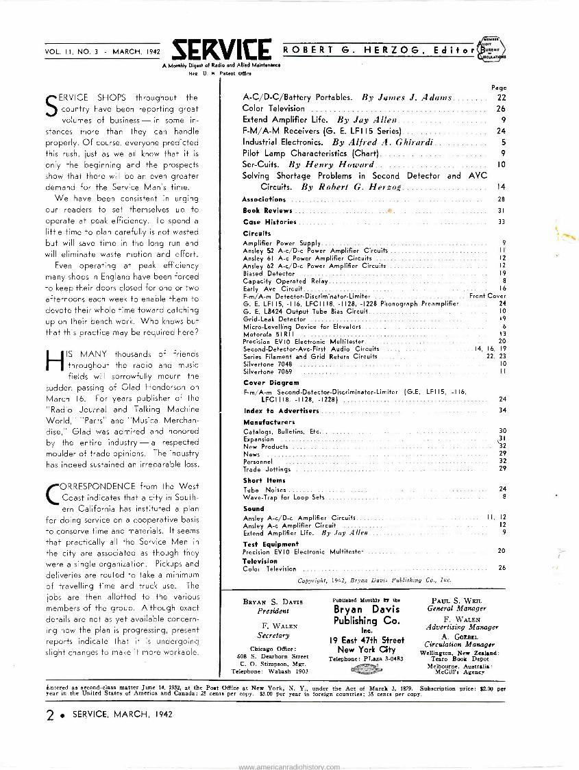
SERVICE SHOPS throughout the
country have been reporting great volumes of business - in some in-
stances more than they can handle
properly. Of course, everyone predicted this rush, just as we all know that it is
only the beginning and the prospects show that there will be an even greater demand for the Service Man's time.
We have been consistent in urging our readers to set themselves up to operate at peak efficiency. To spend a
little time to plan carefully is not wasted
but will save time in the long run and will eliminate waste motion and effort.
Even operating at peak efficiency many shops in England have been forced to keep their doors closed for one or two afternoons each week to enable them to devote their whole time toward catching up on their bench work. Who knows but that this practice may be required here?
HIS MANY thousands of friends throughout the radio and music
fields will sorrowfully mourn the
sudden passing of Glad Henderson on
March 16. For years publisher of the
"Radio Journal and Talking Machine
World," "Parts" and "Musical Merchan- dise," Glad was admired and honored by the entire industry -a respected
moulder of trade opinions. The industry has indeed sustained an irreparable loss.
CORRESPONDENCE from the West Coast indicates that a city in South-
ern California has instituted a plan
for doing service on a cooperative basis
to conserve time and materials. It seems
that practically all the Service Men in
the city are associated as though they were a single organization. Pickups and
deliveries are routed to take a minimum of travelling time and truck use. The
jobs are then allotted to the various members of the group. Although exact
details are not as yet available concern- ing how the plan is progressing, present
reports indicate that it is undergoing slight changes to make it more workable.
MIYtI Uort
UREAU
Page
A-C/D-C/Battery Portables. By Jantes J. Adams 22
Color Television 26 Extend Amplifier Life. By Jay Allen 9
F-M/A-M Receivers (G. E. LFI 15 Series) 24
Industrial Electronics. By Alfred A. Ghirardi 5
Pilot Lamp Characteristics (Chart) 9
Ser -Cuits. By Henry Howard 10
Solving Shortage Problems in Second Detector and AVC Circuits. By Robert G. Herzog 14
Associations 28
Book Reviews +t 31
Case Histories 33
Circuits Amplifier Power Supply 9
Ansley 52 A-c/D-c Power Amplifier Circuits 11
12 Ansley 61 A -c Power Amplifier Circuits Ansley 62 A-c/D-c Power Amplifier Circuits 12
19
8
16
Front Cover 24 10
19
6 13
20
Biased Detector Capacity Operated Relay Early Avc Circuit F-m/A-m Detector -Discriminator -Limiter G. E. LFI 15, -116, 'IC I118, -1128, -1228 Phonograph Preamplifier G. E. LB424 Output Tube Bias Circuit Grid -Leak Detector Micro -Levelling Device for Elevators Motorola 51R11 Precision EVIO Electronic Multitester Second -Detector -Ave -First Audio Circuits 14, 16, 19
Series Filament and Grid Return Circuits 22, 23 Silvertone 7048 10
Silvertone 7069 I I
Cover Diagram F-m/A-m Second -Defector -Discriminator -Limiter (G.E. LF115, -116,
LFCI 118, -1128, -1228) 24
Index to Advertisers
Manufacturers Catalogs, Bulletins, Etc. Expansion New Products News Personnel Trade Jottings
Short Items Tube Noises 24 Wave -Trap for Loop Sets 8
Sound Ansley A-c/D-c Amplifier Circuits I I, 12
Ansley A -c Amplifier Circuit 12
Extend Amplifier Life. By Jay Allen 9
Test Equipment Precision EVIO Electronic Multitester 20
Television Color Television 26
34
Copyright, 1942, Bryan Davit Publishing Co., Inc.
30 ,31
32 29 32 29
BRYAN S. DAVIS
President
F. WALEN
Secretary
Chicago Office 608 S. Dearborn Street
C. O. Stimpson, Mgr. Telephone: Wabash 1903
Puhlleheá Monthly 4 the
Bryan Davis Publishing Co.
Inc.
19 East 47th Street New York Gty
Telephone: PLaza 3-0483
PAUL S. WEIL General Manager
F. WALEN Advertising Manager
A. GOEBEL Circulation Manager
Wellington, New Zealand: Tearo Book Depot
Melbourne, Australia: McGill's Agency
Entered as second-class matter June 14, 1932, at the Post Office at New York, N. Y., under the Act of March 3, 1879. Subscription price: $2.00 per year in the United States of America and Canada; 25 cents per copy. $3.00 per year in foreign countries; 35 cents per copy.
2 SERVICE, MARCH, 1942
www.americanradiohistory.com
"THERE IS A BRIGHT SIDE" --i An Open Letter to Users of Electrical Measuring Instruments
Much more than instruments is needed to fill the vast requirements of America's gigantic production program. Experience gained by many years of actual instrument peace -time needs is answering the call to arms -is doing its part in re-establishing in the world the Democratic ideals of freedom.
Private business must undergo restrictions for the sake of National security. As good Americans we will bear these willingly.
And there is a bright side. Rapid expansion, new fields and improved processes mark today's instrument program. New developments unbe- lievably revolutionary in their scope are growing out of the vast proving ground of war -time production. When war ends, these advantages will be passed on to all of you. From the experience of today will come many new and greatly improved instruments to better serve the peaceful world of tomorrow.
EFENSE
BUY UNITED STATES
SAVINGS BONDS
AND STAMPS
Sales Manager The Triplett Electrical Instrument Co.
We Can All Help .. . Buy Defense Stamps and Bonds. Buying them regu-
larly is the best way you can help General MacArthur and our fighting men. We must all pull together now,
and your dollars can best serve in stamps and bonds.
THE TRIPLETT ELECTRICAL INSTRUMENT COMPANY BLUFFTON, OHIO
SERVICE, MARCH, 1942 3
www.americanradiohistory.com
®heno roa 00.0000 NO. It
Centralab
Ceahalab con+.eln ate a:waye .0 step wnh Dtoptaca i» o.- or dnlenaive use.In"Rac>ful Put.atiü bt.ìi puníeF.I+N, gt.eì
eaCanNalihconholssunhnvetoperiotmamonth.y e othmenty. And when you ate coiled ... remembe that Cnnlealab coNtola are the Alea! top:ace.merJs on evety job C[NT\AlA\t Dívi.i.n e( Gt.b..Unbn int., MNr..NN WO.
Centralab RADIOHMS
Centralab RADIOHMS
C-EV MUD
EtMAREUtF
IEfER9A8!Uï'
Tñeres'
4 SERVICE, MARCH, 1942
7,,z gm/limed
THE lIGNT REPLACEMENT CONTROL" NUN THIS Centralab
T OPTA HLE
CENTRMAé
The history of CENTRALAB can -be read in its advertisements down through the years. New develop- ments ... the result of research and pioneering ... keE p Centralab con- stantly in the vanguard. Today ... research alone is not enough ... the demands of the present emergency call for an "ALL OUT" program of production.
In '42 CENTRALAB will not fail to maintain its record. In '42 as in '22 and '32 . . .
always "SPECIFY CENTRALAB".
CENtM4tA
nI Div. of Globe -Union Int., Milwaukee, Wis.
CONTROLS SWITCHES RESISTORS
CAPACITORS
71/se
www.americanradiohistory.com

ROBERT G. HERZOG, EDITOR
INDUSTRIAL ELECTRONICS
MENTIO was made last month of the important demand, among defense industries and others,
for photoelectric protective devices to help guard against trespassers in gen- eral and saboteurs in particular. Per- haps some readers will wonder why only the installation and maintenance of such equipment was suggested, as providing an opportunity for the radio service fraternity, and no reference made to the possibility of constructing the equipment.
There are a number of reasons why it is impractical for most Service Men to enter this construction field. There is first the basic one that most Service Men learned long ago, that their princi- pal profit lies in selling and servicing equipment, rather than going through the headache of attempting to manufac- ture it themselves. That this lesson was thoroughly learned is indicated by the fact that probably 95 percent or more of all sound installations made within the past few years include commercially - built equipment throughout. Moreover, most of the test instruments and equip- ment which the Service Man himself uses in his business are commercially built units.
Other reasons are found in the pains- taking design which must be incorpo- rated if photoelectric protective equip- ment is to render the highly effective and dependable service demanded of it in industry today. For long light throws, outdoors, complicated precautions must oftentimes be taken to avoid the effect of daylight, reflected glare, etc. This may involve special light shielding, light baffles, or even modulation of the light source, with the phototube detector unit equipped with filters which permit it to react only to a particular light -modula -
By ALFRED A. GHIRARDI
tion frequency. Where mirrors are used to reflect the beam around corners of buildings some designs even go so far as to heat these mirrors to prevent con- densation of moisture on their surfaces because this moisture, repeatedly col- lecting and drying, soon results in cloudiness and greatly decreased ef- fectiveness.
In outdoor service the elements them- selves complicate matters. Fog, dust,
Fig. I. Precision measurements of di- mensions of objects can be made by utilizüng the principle involving change in capacity of a condenser with variations
in spacing between the plates.
snow, rain, blowing leaves or papers- all these can trip a system unless due precautions are taken against them. Then there is a possibility that a smart trespasser might create an artificial light source by holding a lighted match in front of the phototube unit, or shin- ing a flashlight on it, thus enabling him to pass through the normal beam with- out tripping an alarm. Many of the haz- ards of the elements are overcome by the use of an intense light beam, made so through the use of lens systems at the light source housing and at the de- tector. But these introduce complica- tions of their own because they intensify the light by shaping it into a slender shaft of substantially equal diameter
throughout its entire length. This calls for extremely accurate focusing, other- wise a tiny shift of the lamp, lens, or the entire light housing may throw the beam completely off the phototube win- dow. Some of the foregoing are prob- lems of the installation man as well as the manufacturer. They mean that the equipment to be employed must be se- lected with due consideration to the particular problems involved in each individual job, and that it must be in- stalled in such a way as to overcome either of these problems. It is therefore by all means advisable for the Service Man who is entering this field to fa- miliarize himself with the detailed char- acteristics and features of the different makes and types of commercial equip- ment available. He may also well avail himself of such instructive literature as some manufacturers are able to sup- ply. Fortunately, most manufacturers willingly provide an advisory service and the Service Man can take advan- tage of this to aid him in planning and quoting on specific prospective installa- tions.
Automatic Blackout Control All photoelectric alarm and protec-
tive systems are not as complicated as the outdoor type of system referred to above. Many of these are too well known to require discussion here. There is one, however, that is of particular in- terest now and which offers excellent sales prospects. This is the sort illus- trated in one of the accompanying photos, designed for use by storekeepers and others to aid them in observing blackouts at times when their stores are unattended.
There are thousands upon thousands of business places in which same lights
SERVICE, MARCH, 1942 5
www.americanradiohistory.com
are left burning all night as a safety measure, or which have lighted display signs, but where there is no watchman or other person in attendance to turn them out should a blackout alarm be sounded. To avoid serious penalties which are likely to be inflicted for fail- ure to comply promptly (within 5 min- utes) with the requirements of such an alarm owners of such premises have two alternatives: either to turn their lights and signs off when they shut up shop each night, or to install automatic equipment which in case of blackout will turn lights off without human assis- tance. To leave a store without the pro- tection of night lights is inviting bur- glary, not to mention the loss of adver- tising value of illuminated signs and lighted store windows, and it is there- fore likely that the second alternative will be a popular choice. A third choice, that of having a watchman is likely to be economically impractical for the greater majority of stores, offices, etc.
Photoelectric equipments for this pur- pose can be quite simple, consisting of a phototube-relay unit which is so placed that light from the nearest street lamp will fall on its light sensitive window. When a blackout goes into effect street lights will be turned off promptly and this will automatically turn off any lights controlled by such a control unit. When the street lights go on again, after the "all clear" signal, the lights controlled by this unit will likewise go on. Thus the premises are unlighted only during the blackout period. The danger of burglary during blackouts will probably be slight because of super - stiff penalties for anyone apprehended in such an act.
Blackout equipment in many cases will pay for itself by reducing the num- ber of hours that the oftentimes expen- sive night lights and signs are left burn- ing. Usually street lights go on only as dusk deepens, and off at daylight. Store night lights and signs, on the other hand, are often turned on early in
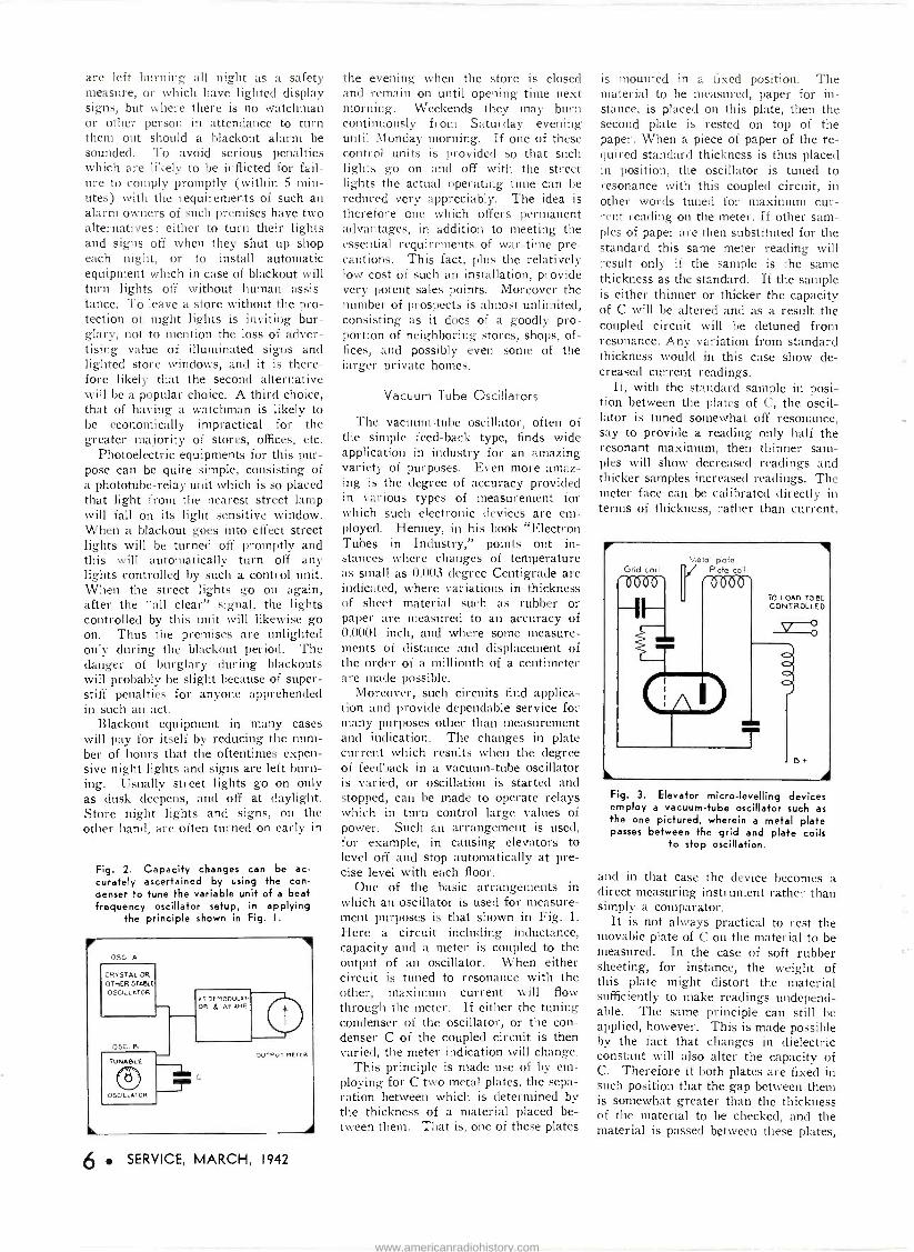
Fig. 2. Capacity changes can be ac- curately ascertained by using the con- denser to tune the variable unit of a beat frequency oscillator setup, in applying
the principle shown in Fig. I.
05C. A
CRYSTAL OR
OTHER STABLE
OSCILLATOR
OSC. B
TUNABLE
OSCILLATOR
V., p,-MJlci a.
OUTPUT METER
6 SERVICE, MARCH, 1942
the evening when the store is closed and remain on until opening time next morning. Weekends they may burn continuously from Saturday evening until Monday morning. If one of these control units is provided so that such lights go on and off with the street lights the actual operating time can be reduced very appreciably. The idea is therefore one which offers permanent advantages, in addition to meeting the essential requirements of war -time pre- cautions. This fact, plus the relatively low cost of such an installation, provide very potent sales points. Moreover the number of prospects is almost unlimited, consisting as it does of a goodly pro- portion of neighboring stores, shops, of- fices, and possibly even some of the larger private homes.
Vacuum Tube Oscillators
The vacuum -tube oscillator, often of the simple feed-back type, finds wide application in industry for an amazing variety of purposes. Even more amaz- ing is the degree of accuracy provided in various types of measurement for which such electronic devices are em- ployed. Henney, in his book "Electron Tubes in Industry," points out in- stances where changes of temperature as small as 0.003 degree Centigrade are indicated, where variations in thickness of sheet material such as rubber or paper are measured to an accuracy of 0.0001 inch, and where some measure- ments of distance and displacement of the order of a millionth of a centimeter are made possible.
Moreover, such circuits find applica- tion and provide dependable service for many purposes other than measurement and indication. The changes in plate current which results when the degree of feedback in a vacuum -tube oscillator is varied, or oscillation is started and stopped, can be made to operate relays which in turn control large values of power. Such an arrangement is used, for example, in causing elevators to level off and stop automatically at pre- cise level with each floor.
One of the basic arrangements in which an oscillator is used for measure- ment purposes is that shown in Fig. 1.
Here a circuit including inductance, capacity and a meter is coupled to the output of an oscillator. When either circuit is tuned to resonance with the other, maximum current will flow through the meter. If either the tuning condenser of the oscillator, or the con- denser C of the coupled circuit is then varied, the meter indication will change.
This principle is made use of by em- ploying for C two metal plates, the sepa- ration between which is determined by the thickness of a material placed be- tween them. That is, one of these plates
is mounted in a fixed position. The material to be measured, paper for in- stance, is placed on this plate, then the second plate is rested on top of the paper. When a piece of paper of the re- quired standard thickness is thus placed in position, the oscillator is tuned to resonance with this coupled circuit, in other words tuned for maximum cur- rent reading on the meter. If other sam- ples of paper are then substituted for the standard this same meter reading will result only if the sample is the same thickness as the standard. If the sample is either thinner or thicker the capacity of C will be altered and as a result the coupled circuit will be detuned from resonance. Any variation from standard thickness would in this case show de- creased current readings.
If, with the standard sample in posi- tion between the plates of C, the oscil- lator is tuned somewhat off resonance, say to provide a reading only half the resonant maximum, then thinner sam- ples will show decreased readings and thicker samples increased readings. The meter face can be calibrated directly in terms of thickness, rather than current,
Fig. 3. Elevator micro -levelling devices employ a vacuum -tube oscillator such as the one pictured, wherein a metal plate passes between the grid and plate coils
to stop oscillation.
and in that case the device becomes a direct measuring instrument rather than simply a comparator.
It is not always practical to rest the movable plate of C on the material to be measured. In the case of soft rubber sheeting, for instance, the weight of this plate might distort the material sufficiently to make readings undepend- able. The same principle can still be applied, however. This is made possible by the fact that changes in dielectric constant will also alter the capacity of C. Therefore if both plates are fixed in such position that the gap between them is somewhat greater than the thickness of the material to be checked, and the material is passed between these plates,
www.americanradiohistory.com

any variations in thickness will vary the capacity.
This latter method is particularly use- ful in maintaining a constant check on the uniformity of materials which are produced in continuous webs or sheets. The measuring head C can be set up anywhere along the production line and therefore does not interfere in any way with the production processes.
The principle involving the change of capacity of C with variations in the spacing between the plates is useful in making precision measurements of vari- ous dimensions of metal objects. This is done by attaching the movable plate of C directly to the pin of a micrometer. Extremely high accuracy of measure- ment is obtained if the spacing between the plates is 0.001 inch, for instance, then a variation of a small fraction of this value will result in material altera- tion of the capacity and therefore of the meter deflection.
For highest accuracy the coupled res- onant circuit must have very low resis- tance. This is sometimes accomplished by removing the measuring instrument from this circuit and placing it in a third circuit which is coupled to the second one. Another method is to em- ploy a vacuum -tube voltmeter to meas- ure the voltage developed directly across the coupling coil L2 of Fig. 1.
Fig. 2 shows another arrangement whereby two oscillators are employed and their demodulated beating outputs measured. In this application one of the oscillators is of fixed and highly stable frequency output, often crystal -con- trolled. The other tunable and across its tuning condenser is shunted an ex- ternal pair of plates similar to those of C in Fig. 1. When this second oscillator is tuned to zero beat with the standard oscillator the output meter shows no reading, but will show readings as the capacity of C is varied. This arrange- ment can be used for many of the same applications as that of Fig. 1, but has the advantage for some purposes that variations in measurement, particularly of transient phenomena, can he made audible or can be recorded.
Still another application of a conven- tional v -t oscillator is that in which the plate current of the oscillator itself is caused to vary by changes in the con- ditions under observation, or of a con- trolling element. An example of this is the equipment employed to provide automatic leveling of elevators as they approach a floor. The principle is illus- trated in Fig. 3.
Here the oscillator is carried on the elevator car and is of a common feed- back type with tuned grid circuit and tickler. If a metal plate is placed be- tween the coils it shields them from one another and stops oscillation. As a re -
The many thousands of signs throughout the country have been put on a war- time basis. In order to comply with the requirements that all lighting visible from the exterior of a
building must be ex- tinguished within five minutes after an air raid alarm General Electric has devel- oped a blackout photoelectric relay. The relay observes the nearest electric street lamp. If lamp is extinguished photo- electric relay will ex- tinguish any electric light connected to
its circuits.
suit the plate current of the tube rises to a much higher level-ample to operate a relay. In the actual application of this device, metal vanes are mounted in the elevator shaft in such position that they come between the coils as the car passes. This stops oscillation and actu- ates the relay. This relay may stop the motor, or may only slow it down. More than one oscillator may be employed, each with its cooperating vanes, at each floor. Thus as a floor is approached one combination may actuate suitable con- trol devices to slow the car to half speed, then another to quarter speed and still another to finally stop it.
Capacity Relays
When one tries to tune an unshielded regenerative tube circuit the effect of body capacity is oftentimes quite marked. This principle is utilized in v -t circuits, known as "capacity relays," de- signed to perform some of the same pro- tective functions as those for which phototubes are employed. For some purposes the capacity relay offers defi- nite advantages, however.
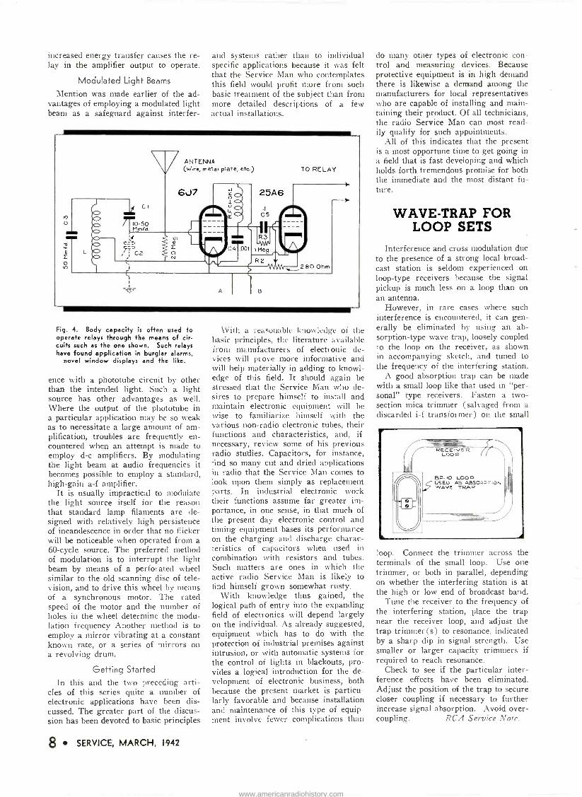
In the case of a phototube burglar alarm, the presence of an intruder is made known when he interrupts the beam of visible or invisible light pro- jected by the light source on to the pho- totube. In the capacity relay system an alarm is actuated by entry of the in- truder into the electrostatic field set up in the vicinity of the "antenna" wire. This antenna may be a single strand of wire extending along the boundaries of a property, or stretched along win- dow and door frames ; or it may be a metal plate on which a small article to be guarded is placed. Anyone approach- ing within perhaps several feet of such a fence, attempting to pass through windows or doors protected by this wir- ing, or coming within the field of the protective plate, will set off an alarm.
The antenna and its capacity to ground is a part of the tube's oscillating circuit in one type of capacity relay, as shown at C2 in Fig. 4. In this case the intensity of oscillation varies ac- cording to the ratio of Cl to C2, the latter being the antenna -to -ground ca- pacity rather than an actual tuning con- denser. A person approaching the an- tenna wire or plate will cause a very ap- preciable increase in the capacity rep- resented by C2, and therefore a large change in this ratio.
The resulting change in r -f potential is reflected in a change in the negative d -c voltage applied to the grid of the 25A6 output tube. This alters the plate current sufficiently to actuate the relay which controls the supply current to the alarm or other device to be controlled.
Capacity relays such as this find ap- plication for a number of other pur- poses. They can be employed to count automobiles passing over a toll bridge, for instance, as a check against the number of tolls collected; to operate motors which automatically open doors as a person approaches them, then close them after the person has passed through; to actuate window displays and advertising gadgets by the wave of the hand, etc.
Another highly sensitive form of ca- pacity relay is one in which the oscil- lator is coupled to the tuned diode in- put of a d -c amplifier through the me- dium of a third tuned circuit. The os- cillator and diode are tuned to the same frequency, but the intermediate coup- ling circuit, in which the antenna -to - ground capacity serves as a portion of the tuning capacity, is detuned suffi- ciently (on the high -frequency side) to provide a low value of energy trans- fer from the oscillator to the diode unit. A person approaching the antenna in- creases the capacity, brings the coup- ling circuit closer to resonance and the
SERVICE, MARCH, 1942 7
www.americanradiohistory.com
increased energy transfer causes the re- lay in the amplifier output to operate.
Modulated Light Beams
Mention was made earlier of the ad- vantages of employing a modulated light beam as a safeguard against interfer-
Fig. 4. Body capacity is often used to operate relays through the means of cir- cuits such as the one shown. Such relays have found application in burglar alarms.
novel window displays and the like.
ence with a phototube circuit by other than the intended light. Such a light source has other advantages as well. Where the output of the phototube in a particular application may be so weak as to necessitate a large amount of am- plification, troubles are frequently en- countered when an attempt is made to employ d -c amplifiers. By modulating the light beam at audio frequencies it becomes possible to employ a standard, high -gain a -f amplifier.
It is usually impractical to modulate the light source itself for the reason that standard lamp filaments are de- signed with relatively high persistence of incandescence in order that no flicker will be noticeable when operated from a 60 -cycle source. The preferred method of modulation is to interrupt the light beam by means of a perforated wheel similar to the old scanning disc of tele- vision, and to drive this wheel by means of a synchronous motor. The rated speed of the motor and the number of holes in the wheel determine the modu- lation frequency Another method is to employ a mirror vibrating at a constant known rate, or a series of mirrors on a revolving drum.
Getting Started
In this and the two preceding arti- cles of this series quite a number of electronic applications have been dis- cussed. The greater part of the discus- sion has been devoted to basic principles
8 SERVICE, MARCH, 1942
and systems rather than to individual specific applications because it was felt that the Service Man who contemplates this field would profit more from such basic treatment of the subject than from more detailed descriptions of a few actual installations.
With a reasonable knowledge of the basic principles, the literature available from manufacturers of electronic de- vices will prove more informative and will help materially in adding to knowl- edge of this field. It should again be stressed that the Service Man who de- sires to prepare himself to install and maintain electronic equipment will be wise to familiarize himself with the various non -radio electronic tubes, their functions and characteristics, and, if necessary, review some of his previous radio studies. Capacitors, for instance, find so many cut and dried applications in radio that the Service Man comes to look upon them simply as replacement parts. In industrial electronic work their functions assume far greater im- portance, in one sense, in that much of the present day electronic control and timing equipment bases its performance on the charging and discharge charac- teristics of capacitors when used in combination with resistors and tubes. Such matters are ones in which the active radio Service Man is likely to find himself grown somewhat rusty.
With knowledge thus gained, the logical path of entry into the expanding field of electronics will depend largely on the individual. As already suggested, equipment which has to do with the protection of industrial premises against intrusion, or with automatic systems for the control of lights in blackouts, pro- vides a logical introduction for the de- velopment of electronic business, both because the present market is particu- larly favorable and because installation and maintenance of this type of equip- ment involve fewer complications than
do many other types of electronic con- trol and measuring devices. Because protective equipment is in high demand there is likewise a demand among the manufacturers for local representatives who are capable of installing and main- taining their product. Of all technicians, the radio Service Man can most read- ily qualify for such appointments.
All of this indicates that the present is a most opportune time to get going in a field that is fast developing and which holds forth tremendous promise for both the immediate and the most distant fu- ture.
WAVE -TRAP FOR LOOP SETS
Interference and cross modulation due to the presence of a strong local broad- cast station is seldom experienced on loop -type receivers because the signal pickup is much less on a loop than on an antenna.
However, in rare cases where such interference is encountered, it can gen- erally be eliminated by using an ab- sorption -type wave trap, loosely coupled to the loop on the receiver, as shown in accompanying sketch, and tuned to the frequency of the interfering station.
A good absorption trap can be made with a small loop like that used in "per- sonal" type receivers. Fasten a two - section mica trimmer (salvaged from a discarded i -f transformer) on the small
BP -1O LOOP USED AS ABS0ao non, WAVE TRAP
loop. Connect the trimmer across the terminals of the small loop. Use one trimmer, or both in parallel, depending on whether the interfering station is at the high or low end of broadcast band.
Tune the receiver to the frequency of the interfering station, place the trap near the receiver loop, and adjust the trap trimmer (s) to resonance, indicated by a sharp dip in signal strength. Use smaller or larger capacity trimmers if required to reach resonance.
Check to see if the particular inter- ference effects have been eliminated. Adjust the position of the trap to secure closer coupling if necessary to further increase signal absorption. Avoid over - coupling. RCA Service Note.
www.americanradiohistory.com

EXTEND AMPLIFIER LIFE
BV THE TIME these lines are read the War Production Board order calling for the end of civilian set
production by April 22 will be common news to everyone in the radio industry. This action is in line with the WPB en- deavor to convert the entire industry 100% to war production. Although ap- peals from this order are being consid- ered, exceptions will be made only as they will help toward the conversion or toward actual war production with in- ventories as a secondary factor. Gov- ernment officials have indicated em- phatically that every usable facility must be converted to war production with every possible speed.
At this writing no date has been set for converting allied industries, such as those that manufacture amplifiers. There seems little doubt, however, but that they, too, will be given the order to stop civilian production in the very near future. Specifically, there are no pros- pects of any further allocations of alumi- num, nickel and other vital metals ex- cept for replacement parts, according to the War Production Board.
All this puts a new responsibility on the Service Man. In the selling of serv- ice on sound equipment he must not only
By JAY ALLEN
Low amp.fuse in primary of power trc nsf.
4111.
A.C. Input
Pilot lamps in series with each plate
of rectifier
RECTIFIER
Filter
To receiver circuits
Fig. I. Several simple changes in the amplifier circuit protect the rectifier and power transformer when shorts develop.
give thought to the repair of actual de- fects but he must also give serious con- sideration to the conservation of the equipment. That is he must attempt to make suitable additions and changes in the equipment which will serve to ex- tend its life or which will act to pre- vent one defect which might develop from causing others. He must also give advice to his customers about conserv-
Fig. 2. Pilot lamps will act as low -current fuses and have the advantage of being less expensive and are universally avail-
able.
MAZDA LAMP
No.
CIRCUIT VOLTS
DESIGN VOLTS
AMPERES AT
DESIGN VOLTS
BASE, MINIATURE BULB BEAD
COLOR MAZDA LAMP
No.
40 6-8 6.3 0.f5 Screw T-31/4 Brown 40 40-A 6-8 6.3 0.15. Bayonet T-3%4 Brown 40-A 41 2.5 2.5 0.5 Screw T-31/4 White 41 42 3.2 3.2 0.35 Screw T-31/4 Green 42 43 2.5 2.5 0.5 Bayonet T-314 White 43 44 6-8 6.3 0.25 Bayonet T-31/4 Blue 44 45 3.2 3.2 0.35 Bayonet T-314 White 45 46 6-8 6.3 0.25 Screw T-314 Blue 45 47 6-8 6.3 0.15 Bayonet T-314 Brown 47 48 2.0 2.0 0.06 Screw T-31/4 PinX 48 49 2.0 2.0 0.06 Bayonet T-31/4 Pink 49 --- 2.1 2.1 0.12 Screw T-31/4 White ---
49-A 2.1 2.1 0.12 Bayonet 7-31/4 - 49-A 50 6-8 -/.5 0.2 Screw G-3%2 White 50 51 6-8 7.5 0.2 Bayonet G-31/2 White 51
--- 6-8 6.5 0.4 Screw G-41/2 White --- 55 6-8 6.5 0.4 Bayonet G -41Y2 White 55 292 2.9 2.9 0.17 Screw 7-3%4 - 292
292-A 2.9 2.9 0.17 Bayonet T-31/4 - 292-A
ing on the use of their sound equipment and on proper handling and storage. Conserving what we have is the duty of every American.
Simple Changes Several simple changes can be made
in the amplifier circuits chiefly to pre- vent slight defects from causing more serious trouble.
Provision for the use of a fuse in the power line input circuits has always been considered good practice. This precaution serves a double purpose. If the user should inadvertantiv connect the equipment to the wrong power source no further damage than a blown fuse will result. And, too, if a short in the wiring or in a component develops, a fuse of the proper current rating will often blow before the excessive drain can take the rectifier and/or the power transformer. The best rating for the fuse is approximately two, or two and a half times, the normal current drain of the equipment.
Service Men have often considered the feasibility of employing additional fuses in series with the plate circuits of the rectifier tube. Should any short at all occur in the amplifier's circuits and cause an abnormal drain on the tube and the power transformer such fuses would blow and would save both of these latter components. More often than not, shorts of this type would not blow the fuse connected in the primary circuit. There seems every reason to include the fuses in the rectifier circuits, but the high cost of fuses with such a low -cur- rent rating and their limited availability have completely restricted their use.
As an alternative for the fuses, a pair of pilot lamps can be used and will serve
(Continued on page 25)
SERVICE, MARCH, 1942 9
www.americanradiohistory.com

Fig. 3. Bias for the output stage in the General Electric LB424 is developed across a resistor in the negative B return.
IT IS Now nearly a year since the first of the priority orders directly affecting radio parts and receivers
went into effect. Since that time manu- facturers have been exceedingly active in developing and producing a variety of alternate and substitute components. Most of these changes made necessary because of shortages of basic materials have been predicted and discussed on the pages of SERVICE months before they were used in the field. The time has come when every new set on the deal- er's shelves shows many of these sub- stitutions.
Trends The very first of the priority orders
was caused by the shortage of alumi- num. New receivers have saved many hundreds of tons of this metal through substitution in dial parts, in variable condensers and in i -f and r -f shield cans.
With few exceptions variable tuning condensers, wherever they are used, are
By HENRY HOWARD
steel throughout both rotor and stator. Similarly, aluminum is no longer used for i -f shield cans. Coil manufacturers shifted to zinc for these cans at first but as production of armaments in- creased this latter metal, too, found its position on the scarce list and a further change was required. The large ma- jority of i -f coils supplied to receiver manufacturers during the last few months used lacquered -iron shields, about ten one-thousandts thick, with a paper -thin copper -foil lining. Although these are more expensive than either aluminum or zinc they work quite well since the copper lining prevents the shorting effect of the iron can. Further substitution along these lines may even see a stiff cardboard shield with a foil lining of copper or maybe with a sprayed copper coating.
Shortages often show peculiar twists for brief periods and metals used for substitutes become scarce while supplies of others are available. Long -terne (lead -plated steel) stock was originally considered as a substitute for other scarcer materials but for the past few months little of this has been available for radio parts. Thus as the shortage of
cadinium makes itself felt, chassis makers are shifting to dull tin or zinc for plating the chassis blanks. While both of these materials are excellent, soldering to the tin plating is consider- ably easier than soldering to the zinc.
Bronze and phosphor -bronze are also high up on the short list. In an effort to save every ounce of these now precious metals, socket manufacturers are using silver-plated steel for socket prongs.
Phonograph motor manufacturers are also cooperating by using ceramic spacers in place of brass screw -machine bushings.
Metals are not alone on the shortage lists. As our arms program speeds up and demands more and more hours of work from machine tools, civilian needs must stand by or resort to substitutes. Die castings and parts made on screw machines give way to stampings. Thus phonograph turntable bearings are no
Fig. I. Silvertone Model 7048 has an r -f fed bias control and a rotating loop antenna as well as a number of other
novel features.
1 NI
K AnNT Cf T?
IOC
f"z
6J5GT Dsc.
R3 IW
0726 270..
-L
1,8C SOCKETS ARE VC WED rROR UNDER SIDE Of CHASSIS. L O.TAGE READPCS STOWS AT SOCK T PRONGS ARE TO CHASSIS. .+NO ARE TAKEN RITO NO SIGNAL, WAVE SWITCH IN BROADCAST r,SITIOH. LINS LOLISGE AT 117 VOLTS. WHERE NO READING IS .,IVEN, THE VOLTAGE IS ZERO OR 00 LOW TO READ.
r
7H7 TRANS
cY
RA
200
Rer 70W
R5 120 L
C QA
C 201 55
KC
C21
12
2.200EG
ARI
two T. cil.E= p '^l-ÿ - ', EE
R q.-A n:152.£
2700 ' ONTROLit
C2
inrwo9. C2]
01
FC ZS
Tpr no¢
65Q7GT CET.- AYC. A.f
6SQ7GT 6K6GT OB 6K6G PHASE INVERTER OUTPUT
BIAS CWTR«.
R20 IRDY 1C39
.DI
1R21 47 ä.
22
70r
IOW
C39
6K6GT oB 6K6G OUTPUT CTS
R23 220.4
R 24 330r
.002
302500100K
3SO, 30rfv0I Ar
I
5 C 35 C56
-__ Or.K. fRC li 7s +.
OpIti 16 i R
5 REG.
5Y3G RECT.
HEATERS DIAL LITE TYPE WA
HEATERS
10 SERVICE, MARCH, 1942
www.americanradiohistory.com

LOOP SOCKET ROT TON VIEW
LOOP PLUG PRONG VIEW
C6 . CZ: 001
C3 CR
C13;
6J5GT BIAS CONTR01
3 0 RI 14C1
R PART Of T2 47W
TARE SOCKETS ARE VIEWED FRON UNDERSIDE OF CHASSIS VOLTAGE READINGS SHOWN AT SOCKET PRONGS ARE TOCHA55IS. AND ARE TAKEN WITH NO SIGNAL, WAVE SWITCH IN BROADCAST POSITION L NE VOLTAGE IT VOLTS WHERE NO READING IS GIVEN THE VO, TACT S ZERO 06 ,00 LOW TO HEAD
6J5GT HOC
R
ßM
7H7 TRANSL
GOR RB
HIGH BOOS'
0 Ip
PHONO RASI SOI CH SWITCH
BASS ROOST SWITCH
R 21 01E23 IMEG
1C2T 2suEG AI
02 CONTROL
6J5GT DET-AVC
PNONO
PL.
PHONO PICK UP
6S07GT
30MFD
11 4
li I
11
2 2MEG
6Sa7GT PHASE INVERT OR
5Y3G RECT ]]
34
ROTOR
100H
T3
6V6G/GT OUTPUT
]eV 933 56. C39
nee HEATERS E4Ò
DIAL LITES PE 44
HEATERS SPEAKER PLUG PRONG PEW
7506, SPEAKER
FIELD
Fig. 2. Silvertone Model 7069 has a
tubeless tuned preselector stage and a
separate oscillator using a 6J5GT tube with a Hartley circuit.
longer of the die-cast type but have been changed to stampings. Dial - drive bushings, previously turned or cast, have also been changed to stamp- ings.
Manufacturers of midget receivers haven turned to housing small sets in cloth -covered wood cases as a substi- tute for the plastic models formerly used. Although plastics may eventually help in overcoming the shortage of metals, other complications have post- poned this for the time being.
The shortage of silk has effects other than curtailing the production of mi- lady's sheer stockings. In the past silk was the most popular insulation cover- ing for coil wire. Its shortage has forced manufacturers to resort to rayon. Since the rayon is heavier it increases the thickness of the covered wire and coils wound from such wire will have a larger diameter. A greater distance be- tween the primary and secondary coils in i -f transformers has been necessary to compensate for the larger diameter of the coils.
Some may look upon substitutions rather pessimistically with a view that anything goes and receivers are "going to the devil". There is no reason for such an attitude, however. We should feel proud that an industry with which we have been personally associated has been ingenious enough to rise to the task of continued production even though the supplies of basic materials has been seriously curtailed. And, too, we can say without hesitation that sets, far from "going to the devil" are no worse for the changes and the industry itself stands to profit greatly by the ex- perience.
When this mess is all over, and the world settles down to peaceful produc- tion once again, manufacturers can feel more free in the design of new models. Substitute materials now in use will provide a wide range of choice and ex- perience for the manufacture of com- ponents when considered with original materials. There will no longer be a need for confining designs around a single type or style because of inexperi- ence with different basic materials.
Continued production of radio re- ceivers for civilian use has passed be -
pending with the avowed purpose of discontinuing such production by the end of April. This is part of the pro- gram designed to convert the entire radio industry 100% to war production.
Such a move will raise the standard of a good many ,of the receiver manu- facturers into the better grade of mer- chandise class. As such they will be called upon to make tank and airplane receivers, direction finders, airplane and submarine locators and other com- plicated radio receiving and transmit- ting equipment. It is almost like making
a
6 L. AST T+ee
14n-
nz(400)
117V AC -DC
SW IN TUNER O O54O
N ,,1 REAR Jr WLUME jrs . CONTROL.
PART %O31
15(400)
11
25L6DoGT
t e
3 -D
a = OHM _1000.0.
=8-
..`. -D-IAssls
yond a matter of ingenuity in the de- velopment of substitute materials. Our tremendous war effort requires concen- tration of every available production facility on the manufacture of ordinance and equipment for our armed forces. Receiver production is already under severe curtailment and an order is
Fig. 4. Ansley Dynaphone Model 52 features a separate amplifier chassis with two 25Z6 rectifiers for a -c/d -c operation.
a high class cabinet maker or piano finisher out of a maker of packing cases.
Curtailment of set production has not
SERVICE, MARCH, 1942 11
www.americanradiohistory.com

as yet affected the regular crop of cir- cuit kinks and we can present plenty of new ones this month, as usual.
Silvertone 7048 Here is a receiver with several fea-
tures worth noting, especially the r -f fed bias -control diode. Fig. 1 shows Sears' Silvertone Model 7048, 8 -tube, 4 -band, 3 -gang push-button job with a rotating loop. Nine buttons are divided as follows: 6 station tuning, low boost, high boost and phono -television -f -m jack. Two 6SQ7GTs are used; the first as the usual detector-avc-first a -f stage, the second as phase inverter and bias control.
The cathode and one diode are grounded. The second diode functions as the bias control, being connected to a junction of a voltage di,vider from the avc bus to ground. This junction is fed r -f from the oscillator through a 0.0001-infd condenser from the 6J5 os- cillator cathode. The diode rectifies the r -f, producing an initial negative bias on the avc bus. The 1-meg resistor al- lows the avc voltage to override the diode bias so as not to interfere with avc action.
Although a 3 -gang condenser is used there is no r -f stage. Instead, the an- tenna circuit is tuned-something like the pre -selection circuits of several years ago. The three tuned circuits are then: antenna; first detector and oscil-
Fig. 5. (Below) The Ansley Model 61
features push-pull 2A3s with woofer and tweeter speakers. Resistance coupled phase -inversion using a 6J5 inverter is
used to obtain the push pull input for the 2A3s.
lator. Note also the i -f regenerative circuit-with a screen grid tickler in the second i -f transformer. The low and high boost are associated with the volume control which is tapped for a bass compensation low -boost effect. This type of control is becoming very common. Likewise with the high boost
by-pasing the high side of the volume control.
Silvertone 7069
Silvertone Model 7069 has many features of the previous set-the same type 3 -gang tuning, i -f regeneration and bias control system. In this model,
7 FAON6 JOCKET.
2516 2516 25, 17L6 615
2/ IF
655
M IN
2556 25Zó 2526 25Z6
CIF 6J50IG 4F .25MF q
i é ñ ó o
6 25L6 w
. .6r PH
6I5o, GT .2550
2546 a
WOOFE
25Z6o,Gr
Il0 r A.C. oD.YC. 2526 .05 MF.
JW/ttN ON REAR
OF rot CONrIIOL
25Z6., G T
FILTER CNdri
v JMF
rWECrfN
64J5 PrIAsE
nYVF7?TLR
OHM I( =1.0009
635 2°AF
605 Dß1vCR
2A3 OUTPUT
r y 1
ao.cT.
VvOOFCR TV2cTER
3wlrC11 IN TLr(R ON RCAR OF WL Ctr1rR0l
MOWN,
MIRE NA)rKLD nYfi[LD
albcor)=4-nN.a4-.=
9(45001 =Zacpsovl
12 SERVICE, MARCH, 1942
Fig. 6. (Above) The Ansley Model 62 is an a -c/d -c job with push-pull parallel 25L6s in the output. Four rectifiers are required to supply the high current for these tubes
and the speaker fields.
however, a separate tube (6J5GT) is used for this latter purpose. Note the 6J5 detector in Fig. 2. Note also the 56 -ohm resistors in the push-pull plates. A single bias cell serves as bias for the first audio.
General Electric LB424
Speaking of bias features, here's a G.E. battery operated table set, Model L.B424 shown in Fig. 3. Five volts for bias purposes is developed by the total plate and screen drain across R. and RE. The total drop is used on the 1A5GT power tube while bias for the 1N5GT i -f stage is taken from the tap. The resistance to ground is so low that no by-passing is required.
Ansley Audio Amplifiers Ansley Radio Corporation has a num-
ber of sets with elaborate audio ampli- fiers which utilize push-pull stages
www.americanradiohistory.com

111
S6AT9T G)t r00
o-,
CO, (2)
11SKrDT
rrt irädi
xcc
100
141 .Gr0.
ie (00-01
n[n á>n Mi
i
N
lOriT D.I-"vD
MAP
rl)
I121 100-E1
eves? jj,,, rOw Or
12))
ge.
,'1 ,as
12a1
110)y
vdl COMT
-11- ie. n
au pp
2' 00 ir0 Rr)
éin
(n)
dru ameein 1.8 ritwl.
IOQ GORUSLW
[wuT ~
al[CTGOM
(
or, ls.l
Segld. Odd
l [O-ro)t'-v
OA10T REGTT
throughout. First we have an a -c, d -c job (Fig. 4) called Dynaphone Model 52. Two 25Z6 rectifiers supply a shunt field and power -stage plates directly and other plate and all screens after the filter section which contains a 5 -henry choke and 45 and 30 mfd filter conden- sers. A 6P5G triode serves as first audio, a 6J5 as second aduio, a 6J5 as inverter and push-pull 25L6s for output. The inverter network is somewhat un- usual in the values of resistors em- ployed. Three equal resistors of 100,000 ohms are used for the grid leaks and degenerative pickup for the inverter grid. These values usually run from 3 - to -1 to 8 -to -1. Two branches of heaters are required because of the dual recti- fiers. Continuously variable treble and bass controls are associated with a tapped volume control similar to the Silvertone model given previously.
Ansley Model 61 is an elaborate a -c receiver with a genuine 3 -gang t -r -f stage, two bandwidth positions, woofer and tweeter speakers with a high-fidel- ity amplifier and no interstage audio transformers. Fig. 5 shows the audio lineup which runs as follows; 6J5 first audio, 6J5 second stage, 6J5 inverter, push-pull 6J5 drivers feeding push-pull 2A3s into the dual speakers. No cath- ode by-passing is used in the second a -f and inverter. Note the bias sup- ply for the output triodes-something we haven't seen much of lately-which consists of a separate rectifier (type 45 as a diode) of low internal re- sistance loaded with a 4,000 -ohm re- sistor and filtered with 8 and 20 mfd condensers and a 25,000 -ohm resistor.
Both speakers are electros and the fields are excited after a filter section con- sisting of 8 and 15 mfd condensers and a 4 -henry choke in order to obtain hum - free performance without hum-buckers and other gadgets. A single 5U4G rec- tifier supplies the entire B demand.
Another Ansley, Model 62, (Fig. 6) for a -c, d -c operation, has a push-pull, parallel 25L6 output stage. 6J5s in first and second a -f feed this combina- tion. Four 25Z6 rectifiers are required for the high current required by the power stage and the woofer and tweet- er fields which are in series across the B supply. Thus, with low plate volt- age and high current-much higher than usually found-the load impedance of the half -wave rectifier is very low. This presents a sizeable filter problem. One way to lick it is with the aid of a carefully designed filter. The one used is a combination of brute force methods and a specially designed tuned filter (tuned to 60 cycles). The brute force practice is to pile on as much capacity as you can get away with and use as big a choke as you can afford. The con- densers used here are 105 and 120 mfd and the choke does double duty as choke and inductance element in the anti -reso- nant 60 -cycle trap. The 25 -ohm resist- ors in series with each rectifier tube limit the surge current and also serve to balance the load equally among the rec- tifiers.
Motorola 51 R I I
We next have a recorder job, Mo- torola Model 51R11, with several inter -
Fig. 7. Motorola Model SIR I is a re- corder combination in which the 6SK7GT i -f amplifier tube serves as a microphone amplifier during recording. Two neon lamps serve to indicate volume level.
esting features. (See Fig. 7). First, the 6SK7GT i -f amplifier is made to serve also as a microphone amplifier. The i -f transformer windings in the grid and plate circuits are left in the circuit at all times as the impedance is too low at audio frequencies to cause any trouble. A 220,000 -ohm resistor is switched in as a plate load in the audio position. It is shorted in the i -f posi- tion to give maximum gain.
The output circuit is of equal inter- est. The primary of the output trans- former serves as an autotransformer with step-up to match the high imped- ance crystal cutter. An equalizer net- work is used for correct cutting charac- teristics. An unbalanced bridge circuit is also fed from the power tube for re- corder level indication. The figure shows two neon lamps designated "Re- cording" and "Too loud." For correct recording level, the first should glow most of the time but the peaks must be watched so the second lamp lights only occasionally. The two audio stages derive grid bias from a divider in the negative high voltage lead.
Degeneration is provided in the out- put stage by connecting the cathode of the power tube directly to the secondary of the output transformer.
To win this war will take lots of money. You can help if you buy
U. S. Defense Bonds and Stamps.
SERVICE, MARCH, 1942 13
www.americanradiohistory.com
SOLVING SHORTAGE PROBLEMS
In Second Detector and
AVC Circuits
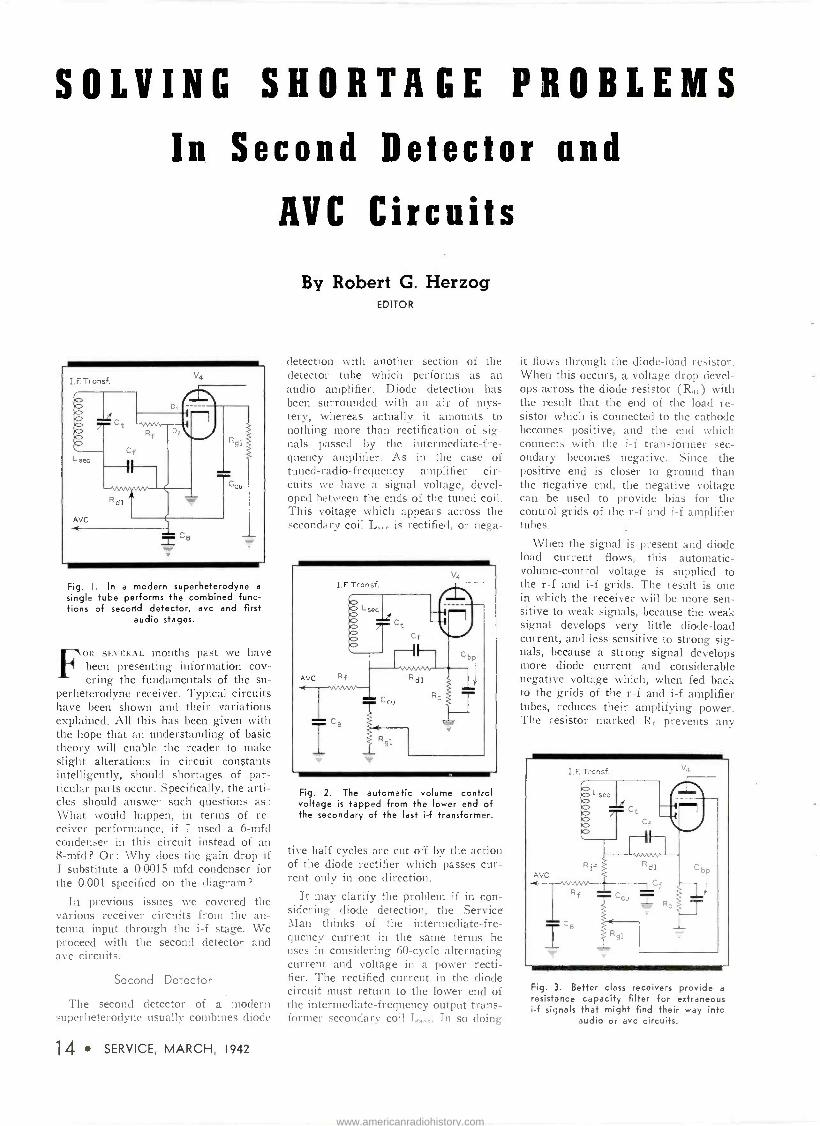
Fig. I. In a modern superheterodyne a
single tube performs the combined func- tions of second detector, avc and first
audio stages.
OR SEVERAL months past we have been presenting information cov- ering the fundamentals of the su-
perheterodyne receiver. Typical circuits have been shown and their variations explained. All this has been given with the hope that an understanding of basic theory will enable the reader to make slight alterations in circuit constants intelligently, should shortages of par- ticular parts occur. Specifically, the arti- cles should answer such questions as :
What would happen, in terms of re- ceiver performance, if I used a 6-mfd condenser in this circuit instead of an 8-mfd? Or: Why does the gain drop if I substitute a 0.0015 mfd condenser for the 0.001 specified on the diagram?
In previous issues we covered the various receiver circuits from the an- tenna input through the i -f stage. We proceed with the second detector and avc circuits.
Second Detector
The second detector of a modern superheterndvne usually combines diode
14 SERVICE, MARCH, 1942
By Robert G. Herzog EDITOR
detection with another section of the detector tube which performs as an audio amplifier. Diode detection has been surrounded with an air of mys- tery, whereas actually it amounts to nothing more than rectification of sig- nals passed by the intermediate -fre- quency amplifier. As in the case of tuned -radio -frequency amplifier cir- cuits we have a signal voltage, devel- oped between the ends of the tuned coil. This voltage which appears across the secondary coil L.- is rectified, or nega -
Fig. 2. The automatic volume control voltage is tapped from the lower end of the secondary of the last i -f transformer.
tive half cycles are cut off by the action of the diode rectifier which passes cur- rent only in one direction.
It may clarify the problem if in con- sidering diode detection, the Service Man thinks of the intermediate -fre- quency current in the same ternis he uses in considering 60 -cycle alternating current and voltage in a power recti- fier. The rectified current in the diode circuit must return to the lower end of the intermediate -frequency output trans- former secondary coil L,,,,.. In so doing
it flows through the diode -load resistor. When this occurs, a voltage drop devel- ops across the diode resistor (R,,,) with the result that the end of the load re- sistor which is connected to the cathode becomes positive, and the end which connects with the i -f transformer sec- ondary becomes negative. Since the positive end is closer to ground than the negative end, the negative voltage can be used to provide bias for the control grids of the r -f and i -f amplifier tubes.
When the signal is present and diode load current flows, this automatic - volume -control voltage is supplied to the r -f and i -f grids. The result is one in which the receiver will be more sen- sitive to weak signals, because the weak signal develops very little diode -load current, and less sensitive to strong sig- nals, because a strong signal develops more diode current and considerable negative voltage which, when fed back to the grids of the r -f and i -f amplifier tubes, reduces their amplifying power. The resistor marked R, prevents anv
Fig. 3. Better class receivers provide a
resistance capacity filter for extraneous i -f signals that might find their way into
audio or avc circuits.
www.americanradiohistory.com
Do Your Customers Know a
BARGAIN When They See It? Øx*
45 powerful 11 volt cells packed in the smallest possible space!
AMIRACLE of compact power-the greatest "B" battery value ever wrapped up in such a small package!
It's the battery that "personal" radio sets were designed around!... the "Eveready" "Mini -Max" Radio "B' Battery No. 467.
Yet customers sometimes speak of its expense! That's because they don't realize what they're buy-
ing-they look at the small size output. It does a man-sized job!
There's your answer for such customers-in the cutaway picture above.
Or put it another way: Many batteries twice the size deliver less power. No wonder the "Eveready" "Mini -Max" Radio "B" Battery No. 467 is such a whale of a bargain!
"EVEREADY"
"MINI -MAX" RADIO "B" .BATTERIES
instead of the big
NATIONAL CARBON COMPANY, INC. Unit of Union Carbide and Carbon Corporation
The words "Eveready" and "Mini -Max" are registered trade -marks of National Carbon Company, Inc.
SERVICE, MARCH, 1942 15
www.americanradiohistory.com

Fig. 4. The earliest ave circuit employed a separate tube in a rather involved cir- cuit with plate and cathode voltage
below chassis potential.
intermediate -frequency energy which may be present from being fed back to the early stages of the receiver where it might cause oscillation.
It will be noted in the accompanying diagrams that the diode -load resistor is by-passed with a condenser of low ca- pacity. This is essential to act as a by-pass for any intermediate -frequency voltage developed at this point. Of course, the condenser must be small or it will by-pass the audio -frequency volt- age across the diode -load resistor.
The rectified carrier signal produces a pulsating current in the diode -load re- sistor and the envelope of these pulsa- tions (line drawn through the peak of each) has variations up and down cor- responding exactly with the voice or music contained in the original signal. These audio variations are fed to the grid of the amplifier section of the sec- ond detector through a coupling con- denser, designated C., of medium ca- pacity. The automatic volume control bus connects to the grid circuits of the r -f and the i -f amplifier tubes through R,.
Early receivers, both t -r -f and super- heterodyne types, employed detectors of the grid leak or bias type. They have enjoyed a rather limited use during the last few years.
Individual Variations
A second -detector circuit, with the volume control acting as the diode -load resistor (Rd,) is shown in Fig. 1. In this circuit the second diode (D,) acts as a gas gate to prevent positive bias from developing on the avc bus in the advent that one of the tubes becomes gassy.
16 SERVICE, MARCH, 1942
In circuits of this type the volume control will be specified between 0.5 to 1.0 meg and C. between 100 and 250 mmfd. Values for R. will vary from 0.5 to 3.3 meg in models of different manufacture, although 2.2 meg has been most popular in the last year or so. Its value is not critical. The value chosen for C. in the design of the receiver depends upon that selected for R.I. The former varies from 0.02 to 0.001 mfd and the latter from 1 to 15 meg. The two should vary in opposite directions ;
that is to say, if the resistor value is high, then the condenser will have a low capacity.
In this type of circuit where the ca- thode and the heater of the tube is grounded, hum caused by cathode to heater leakage is a negligible factor, since the two elements are at the same potential.
In Fig. 2 the volume control is con- nected in the grid circuit of the audio section of the tube. The diode -load re- sistor (Ra,) is of the pigtail carbon type
Fig. 5. Some receivers use only half of the avc voltage on the earlier stages of the receiver to assist in reception of
weak signals.
and again has a value between 0.5 and 1
meg. Volume control action in this type of circuit is usually quieter than in that of Fig. 1, since there is no d -c present in the element. Values for the volume control (Rs,) come between 0.5 and 2 meg and the coupling condenser (C.1) would correspond, somewhere between 0.02 and 0.006 mfd, varying in the op- posite direction. The value of either is not critical, although the taper on the volume control is important.
The bias voltage for the audio -ampli- fier section of the tube is obtained by the use of the cathode resistor (R.). The cathode current flowing to ground makes the upper end of this resistor positive and the lower end negative. It will be noted that the avc bus connects
to the grid circuits of the i -f and r -f tubes through R. and then through the diode -load resistor (Ra,) to the upper end of the cathode bias resistor (R.). When no signal is present there will be no avc voltage developed. The positive voltage developed across R. by the ca- thode current flowing through it, will be impressed on the grids of the r -f and i -f tubes. With 6SQ7 and similar type tubes this positive voltage is ap- proximately 1.5 volts. It must be over- come by a greater cathode bias voltage developed in the cathode resistor for the individual r -f and i -f tubes.
Resistances used for cathode bias (R.) in circuits of this type vary from 1,000 to 15,000 ohms, depending upon the particular type of tube chosen and the other constants in the circuit. Its value is not very critical. The by-pass condenser is generally of the low -volt- age electrolytic type with a capacity ranging from 5 to 25 mfd. The use of a high capacity condenser is important in this circuit because the difference of potential between the cathode and heater increases the hum leakage from this source. The condenser must present a low -impedance path around the re- sistor for such leakage.
Fig. 3 is the same as Fig. 2 except for the addition of the i -f filter, R11 and Cr. These act in conjunction with the original filter condenser (Cr) to cut out any i -f that might attempt to enter the audio or avc circuits. The value of R,t is not at all critical and may range from 25,000 to 100,000 in models of different manufacture. Cr is not critical either, and may range from 100 to 250 mmfd, although where two are used the indi- vidual values will range toward the lower capacities.
One of the earliest avc circuits is
(Continued on page 19)
Fig. 6. A type of delayed avc imposed an initial bias on the circuit in an at- tempt to make the set more sensitive to
weak signals.
www.americanradiohistory.com

WHERE YOU FIND NATIONAL UNION
YOU FIND BETTER RADIO SERVICE
Radio Tubes More Rad o Service
Dealers us.' National Union than any other make ... there must be a good reason why.
Condensers Complete line . Same Super Quality as found in N. U. Tubes. Just try them.
Sound Extra Tubes . a line of heavy
duty radio tubes for sound work . . . an exclusive N. U. develop. ment.
Batteries The only line of
Dry Batteries sold ex- clusively to the radio Trade . . . Yoat can make more money.
1
Mr. James Mea
"I hase use N. U. tubes for tl product like N. U. goes a long way between customer and service ratan.
ideal for ail servicemen."
James Means Radio Service N. Little Rock, Arkansas
st ten years. ,I reliable :ard promoting good will N. U. Equipment Plan is
NAT ° a NAL UNION invites .. .
11 radio service dealers to enjcy the benefits of the U. Shop Equipment Plan. The latest in tube testers
nd test equipment re available to you, immediate delivery. More than0,000 completed deals prove the success of this plan. Investigate now.
Ask Your N. U. Distributor or W
NOW - NATIONAL UNION TRANSMITTING TUBES
Recently announced, a complete line of National Union Transmitting Tubes in all important sizes to 200 watts. Same premium quality as found' in N.U. receiving tubes.
SERVICE, MARCH, 1942 17
www.americanradiohistory.com
If your problem is weight
(our smallest units weigh
only one-third ounce) or
size (our sheet metal di-
vision can run off a case to
accurately fit your particu-
lar requirements) or pre-
cise adjustments or
tougher than ordinary elec-
trical characteristics or
mechanical requirements or submersion type com-
ponents, etc.... CHECKING AUDIO FILTERS AT UTC
UTC IS THE LOGICAL SOURCE MAY WE ASSIST YOU? A note to our Engineering Division will bring a quick response
with details on units to your requirements.
EXPORT DIVISION: 100 VARICK STREET NEW YORK, N Y CABLES: "ARLAB" www.americanradiohistory.com
SOLVING SHORTAGE PROBLEMS
IN SECOND DETECTOR AND
AVC CIRCUITS
( Continued from page 16)
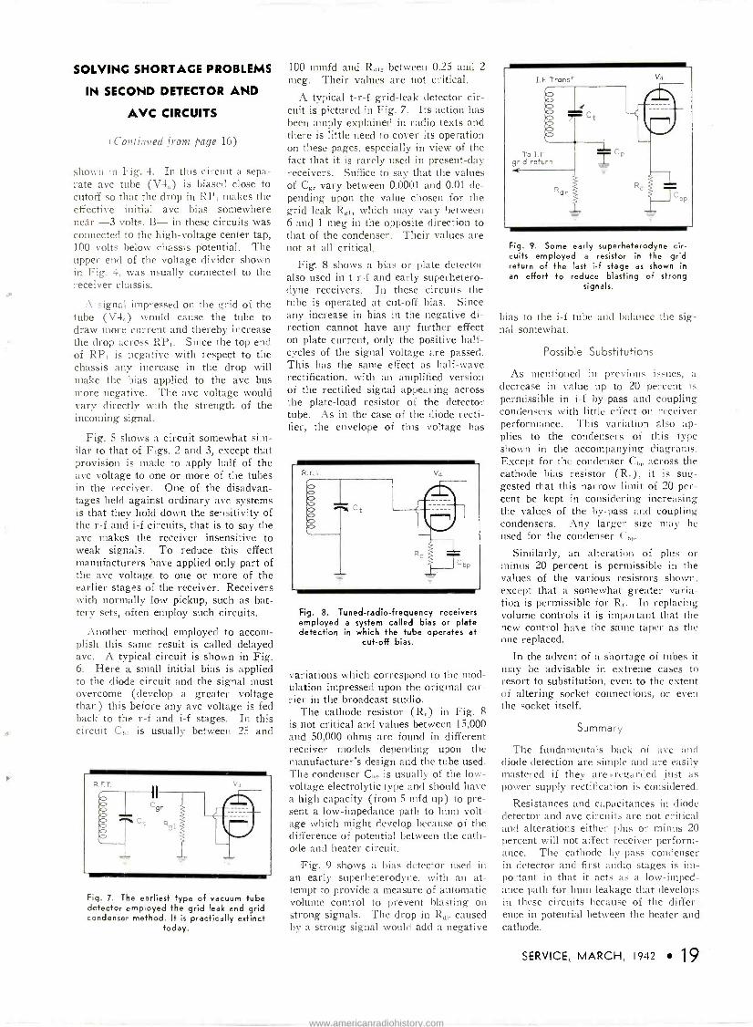
shown ill Fig. 4. In this circuit a sepa- rate avc tube (V4,) is biased close to cutoff so that the drop in RP, makes the effective initial avc bias somewhere near -3 volts. B- in these circuits was connected to the high -voltage center tap, 100 volts below chassis potential. The upper end of the voltage divider shown in Fig. 4, was usually connected to the receiver chassis.
A signal impressed on the grid of the tube (V4;,) would cause the tube to draw more current and thereby increase the drop across RP,. Since the top end of RP, is negative with respect to the chassis any increase in the drop will make the bias applied to the avc bus more negative. The avc voltage would vary directly w _th the strength of the incoming signal.
Fig. 5 shows a circuit somewhat sim- ilar to that of Figs. 2 and 3, except that provision is made to apply half of the avc voltage to one or more of the tubes in the receiver. One of the disadvan- tages held against ordinary avc systems is that they hold down the sensitivity of the r -f and i -f circuits, that is to say the avc makes the receiver insensitive to weak signals. To reduce this effect manufacturers have applied only part of the avc voltage to one or more of the earlier stages of the receiver. Receivers with normally low pickup, such as bat- tery sets, often employ such circuits.
Another method employed to accom- plish this same result is called delayed avc. A typical circuit is shown in Fig. 6. Here a small initial bias is applied to the diode circuit and the signal must overcome (develop a greater voltage than) this before any avc voltage is fed back to the r -f and i -f stages. In this circuit Cb, is usually between 25 and
Fig. 7. The earliest type of vacuum tube detector emp oyed the grid leak and grid condenser method. It is practically extinct
today.
100 mmfd and Rd,, between 0.25 and 2
meg. Their values are not critical.
A typical t -r -f grid -leak detector cir- cuit is pictured in Fig. 7. Its action has been amply explained in radio texts and there is little need to cover its operation on these pages, especially in view of the fact that it is rarely used in present-day receivers. Suffice to say that the values of Cgr vary between 0.0001 and 0.01 de- pending upon the value chosen for the grid leak Rg,, which may vary between 6 and 1 meg in the opposite direction to that of the condenser. Their values are not at all critical.
Fig. 8 shows a bias or plate detector also used in t -r -f and early superhetero- dyne receivers. In these circuits the tube is operated at cut-off bias. Since any increase in bias in the negative di- rection cannot have any further effect on plate current, only the positive half - cycles of the signal voltage are passed. This has the same effect as half -wave rectification, with an amplified version of the rectified signal appearing across the plate -load resistor of the detector tube. As in the case of the diode recti- fier, the envelope of this voltage has
R.FT.
= i p
Fig. 8. Tuned -radio -frequency receivers employed a system called bias or plate detection in which the tube operates at
cut-off bias.
variations which correspond to the mod- ulation impressed upon the original car- rier in the broadcast studio.
The cathode resistor (Re) in Fig. 8 is not critical and values between 15,000 and 50,000 ohms are found in different receiver models depending upon the manufacturer's design and the tube used. The condenser Chp is usually of the low - voltage electrolytic type and should have a high capacity (from 5 mfd up) to pre- sent a low -impedance path to hum volt- age which might develo.p because of the difference of potential between the cath- ode and heater circuit.
Fig. 9 shows a bias detector used in an early superheterodyne, with an at- tempt to provide a measure of automatic volume control to prevent blasting on strong signals. The drop in Rd, caused by a strong signal would add a negative
Fig. 9. Some early superheterodyne cir- cuits employed a resistor in the grid return of the last i -f stage as shown in an effort to reduce blasting of strong
signals.
bias to the i -f tube and balance the sig- nal somewhat.
Possible Substitutions
As mentioned in previous issues, a decrease in value up to 20 percent is permissible in i -f by-pass and coupling condensers with little effect on receiver performance. This variation also ap- plies to the condensers of this type shown in the accompanying diagrams. Except for the condenser C,,, across the cathode bias resistor (R,.), it is sug- gested that this narrow limit of 20 per- cent be kept in considering increasing the values of the by-pass and coupling condensers. Any larger size may he used for the condenser C,,,.
Similarly, an alteration of plus or minus 20 percent is permissible in the values of the various resistors shown, except that a somewhat greater varia- tion is permissible for R,,. In replacing volume controls it is important that the new control have the same taper as the one replaced.
In the advent of a shortage of tubes it may be advisable in extreme cases to resort to substitution, even to the extent of altering socket connections, or even the socket itself.
Summary
The fundamentals back of ave and diode detection are simple and are easily mastered if they are.regarded just as power supply rectification is considered.
Resistances and capacitances in diode detector and avc circuits are not critical and alterations either plus or minus 20 percent will not affect receiver perform- ance. The cathode by-pass condenser in detector and first audio stages is im- portant in that it acts as a low -imped- ance path for hum leakage that develops in these circuits because of the differ- ence in potential between the heater and cathode.
SERVICE, MARCH, 1942 19
www.americanradiohistory.com
A dozen people have asked
us: "What has the war done
to Radiart Vibrators?" Our
answer is: "Nothing." Pos-
sibly, the needs of our war
production may some day
compel substitutions for some
of the materials employed in
Radiart Vibrators, but that
has not yet happened. Oh,
sure, we've used tin containers
instead of zinc in a few
models; but that doesn't in
the least affect the operation
of the vibrators.
Up to now, no changes of
any kind have been made. If changes should be necessary,
we assure you that we are pre-
pared with well -laid plans for
substitutions which will main-
tain the high standards of
precision and long operating life which are characteristic of
Radiart Vibrators.
RADIART VIBRATORS are now doing a bang-up job of keeping the nation's pas-
senger cars, police cars, utility and other mobile radio equip- ment ready for action. Depend upon Radiart to continue.
THE RADIART CORP. Cleveland, Ohio
20 SERVICE, MARCH, 1942
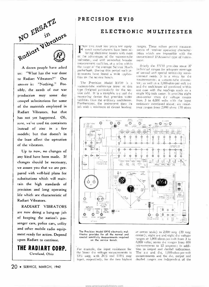
PRECISION EV10
ELECTRONIC MULTITESTER
FOR THE PAST few years test equip- ment manufacturers have been of- fering electronic testers with most
of the advantages of the vacuum -tube voltmeter, and with somewhat broader measurement facilities, at a price within the range of the average Service Man's pocketbook. During this period such in- struments have found a wide applica- tion on the service bench.
The Precision Model EVIO is a vacuum -tube multirange tester of this type designed particularly for the ser- vice field. It is a complete a -c and d -c measuring device that provides wider facilities than the ordinary multitester. Furthermore, the instrument does its job with a minimum of circuit loading.
ranges. These values permit measure- ments of receiver operating character- istics which are impossible with the conventional D'Arsonval type of instru- ment.
Briefly the EVIO provides some 37 individual ranges for adequate coverage of normal and special sensitivity meas- urement needs. It is a vtvm for d -c measurements; a vacuum -tube ohmme- ter ; as well as a 1,000 -ohm -per -volt a -c and d -c multitester all combined within one case with the readings made on a single 8% -inch meter. It provides eight zero -center vtvm d -c voltage ranges from 3 to 6,000 volts with the input resistance mentioned above; six resist- ance ranges from 2,000 ohms (20 ohms
POSITIONS
CÉNTEP B -Bol rom
®
9400
11 NO
PPS 1000.
Bra 28.40
"VS
00 '+ ,1.if:r5 outPi+r
CO' .36w 267 a
c
106'/i 39[G
P2 640 13,3 l'/l MEG
c. poop í200v 3v TO 0000
PII PI? P l P . P 5
00 6000 839
o E4W
0 1.2...
0 i
6.4w
f
32w 120.0 640w
0 f F
07
ó ó ó Ó Ô Ó O o _fN~EP OEJ.
o.
0 o
0 0 ^0 Q Y
s 1 F 2"2 0WÓ
0 0 4 O O O 0
n[ 0 2E 46p39 G
60Mw
4715 w
P3> 20w;
P. l# 1324 N Pr
000w 2061w tern
,1,960
=6V. el 4. .-
J 52
G.
SP t,1 olGr. an
MELOnMMETEO y0
p ó` S1 1.iNEt.uOG
(2)14MP USES
The Precision Model EVIO electronic mul- titester provides for all the normal and special sensitivity measurements required
on the service bench.
For example, the input resistance for the lower d -c voltage measurements is 13V2 meg, with 262/3 and 133% meg input, respectively, for the two highest
at center scale) to 2,000 meg (20 meg center) ; eight a -c and eight d -c voltage ranges at 1,000 -ohms -per -volt from 3 to 6,000 volts; seven d -c ranges from 600 microamperes to 12 amperes; in addi- tion to output and decibel indications. The a -c and d -c, 1,000 -ohm -per -volt measurements and the d -c, output and decibel ranges are independent of the
www.americanradiohistory.com

power line and the instrument need not be connected to the line to make these measurements
Careful design features provide ad- ditional operating advantages. Employ- ing the ohmmeter circuits, for instance, there is no necessity to short the test leads to check the zero adjustment, and no readjustment of zero is necessary when shifting from one range to an- other. The resistance ranges do not re - (luire high voltage and are all powered from a self-contained 6 -volt battery. Since the meter itself is not directly connected to the measuring circuits, when the instrument is employed in its electronic functions, there is no possi- bility of damage by inadvertently check- ing a live resistor or by using too low a measurement range.
A stabilized bridge type circuit em- ploys a 6C5GT as a voltage amplifier, a 6X5GT as power supply rectifier and a VR150 as plate voltage regulator. This latter tube holds the plate voltage to the amplifier tube constant in spite of variation in line voltage and makes for greater accuracy of measurement.
An additional facility is optionally available in the form of the "Series RFIO Vacuum Probe," which is directly attachable, by means of a plug-in cable, to the front of the EV10 panel. Incorpo- rating a 955 acorn -type tube, this latter accessory provides for direct measure- ment of a -f and r -f voltages. All the necessary operating voltages for the 955 tube are applied from the EV1O through the connecting plug and cable.
Specifications Line power : 105 to 125 volts, 50 to 60
cycles. Controls : Master range selector ; circuit
selector ; vtvm zero adjustor ; ohms zero adjustor; and ohms zero check.
Meter : 81/2 -inch square, 400 microampere D'Arsonval type; 60 scale divisions.
Ranges: 8 zero -center vtvm ranges to 3, 6, 12, 60, 300, 600, 1,200, and 6,000 volts d -c.
Input resistance 131/2 meg on six lower ranges; 262/3 meg on 1,200 -volt range and 133/3 meg on 6,000 -volt range.
6 resistance ranges from 0 to 2,000 and 200,000 ohms, to 2, 20, 200 and 2,000 megohms.
8 d -c voltage ranges, at 1,000 -ohms -per - volt, from 0 to 3, 6, 12, 60, 300, 600, 1,200 and 6,000 volts.
8 a -c voltage ranges, at 1,000 -ohms -per - volt, from 0 to 3, 6, 12, 60, 300, 600, 1,200 and 6,000 volts.
7 direct current ranges from 0 to 600 microamperes and from 0 to 3, 12, 60, 300 and 1,200 milliamperes and from 0 to 12 amperes.
Built-in blocking condenser for a -c out- 'rt ranges ; 8 decibel ranges from -26
to +70 db. Dimensions: 10,/, by 12 by 6 inches. Finish : Available in black oven baked
crinkle or hardwood walnut portable case.
Reetemilw' WE DON'T EXACTLY MEAN that folks are going back to these coughing, wheezing, high -back models; but you don't have to be so very old to remember that even in those days people liked their convenience and comfort and entertainment. They took their cars "f.o.b." and added a horn, a top, a spare tire (no 3 or 4 spares). They even added a
windshield, sometimes. Then, as now, it wasn't enough just to get there and back; the American idea has always been to go in style-in comfort-and fast.
Since radio has become a com- monplace of American life, mo- torists have considered the car radio a "must" In these tense times, especially, a car radio is not merely a means of inexpensive entertainment-it is news-an eager public's indispensable con- tact with stirring events, the world over.
While engaged in winning this war, Americans will be advised by authorities to maintain morale on the home front-to get all the convenience and recreation that can be extracted from our present cars as long as they last.
The American people will learn, as never before, to take good care of irreplaceable possessions. They will apply that proverbial stitch in time. They'll keep their
cars and tires in first-class shape; and, as for their car radios-we'll nót hear any more "Oh, let it go; I'm 'trading my car soon." Those radios-many millions of them -will be in working order-you just depend on that.
Sure, we'll all be driving less- but when we do drive, we'll not put up with a radio that's on the bum.
Does this mean that RADIART AERIALS will be selling? It sure does. It means that the man who put off replacing that old, battered, rusty aerial-or the aerial that's too short to "bring 'em in"-because he figured on trading his car-that fellow- two million strong-will be driv- ing this car with this radio. A NEW Radiart Aerial will be his big chance to step up his radio performance.
And this is the BIG CHANCE for the Radiart distributor- serviceman, dealer, jobber-to step up aerial sales. It's good volume, profitable volume, at a time when volume and profits are most welcome. And best of all, because substitute materials not vital to defense have been em- ployed where needed, RADIART CAN DELIVER and expects to continue delivering.
THE RADIART
CORP. Cleveland, Ohio
(77)
SERVICE, MARCH, 1942 21
www.americanradiohistory.com
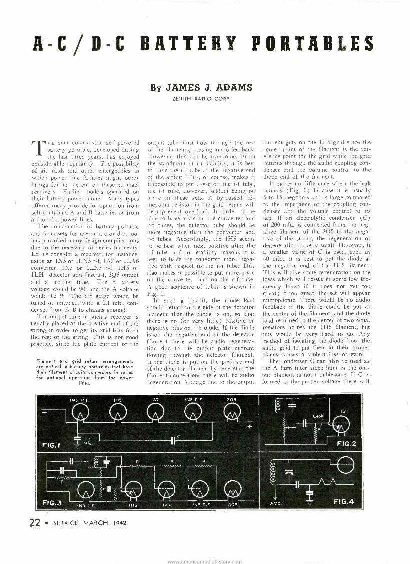
A-C/D.0 BATTERY PORTABLES
TIlE SELF-CONTAINED, self -powered battery portable, developed during the last three years, has enjoyed
considerable popularity. The possibility of air raids and other emergencies in which power line failures might occur brings further accent on these compact receivers. Earlier models operated on their battery power alone. Many types offered today provide for operation from self-contained A and B batteries or from a -c or d -c power lines.
The construction of battery portable and farm sets for use on a -c or d -c, too, has provoked many design complications due to the necessity of series filaments. Let us consider a receiver, for instance, using an 1N5 or 1LN5 r -f, 1A7 or 1LA6 converter, 1N5 or 1LN5 i -f, 1H5 or 1LH4 detector and first a -f, 3Q5 output and a rectifier tube. The B battery voltage would be 90, and the A voltage would be 9. The r -f stage would be tuned or untuned, with a 0.1 mfd. con- denser from A -B to chassis ground.
The output tube in such a receiver is usually placed at the positive end of the string in order to get its grid bias from the rest of the string. This is not good practice, since the plate current of the
Filament and grid return arrangements are critical in battery portables that have their filament circuits connected in series for optional operation from the power
lines.
By JAMES J. ADAMS ZENITH RADIO CORP.
output tube must flow through the rest of the filaments, causing audio feedback. However, this can be overcome. From the standpoint of i -f stability, it is best to have the i -f tube at the negative end of the string. This, of course, makes it impossible to put a -v -c on the i -f tube, the i -f tube, however, seldom being on a -v -c in these sets. A by-passed 15- megohm resistor in the grid return will help prevent overload. In order to be able to have a -v -c on the converter and r -f tubes, the detector tube should be more negative than the converter and r -f tubes. Accordingly, the 1H5 seems to be best when next positive after the i -f tube, and for stability reasons it is best to have the converter more nega- tive with respect to the r -f tube. This also makes it possible to put more a -v -c un the converter than on the r -f tube. A good sequence of tubes is shown in Fig. 1.
In such a circuit, the diode load should return to the side of the detector filament that the diode is on, so that there is no (or very little) positive or negative bias on the diode. If the diode is on the negative end of the detector filament there will be audio regenera- tion due to the output plate current flowing through the detector filament. If the diode is put on the positive end of the detector filament by reversing the filament connections there will be audio degeneration. Voltage due to the output
current gets on the 1H5 grid since the center point of the filament is the ref- erence point for the grid while the grid returns through the audio coupling con- denser and the volume control to the diode end of the filament.
It makes no difference where the leak returns (Fig. 2) because it is usually 5 to 15 megohms and is large compared to the impedance of the coupling con- denser and the volume control to its tap. If an electrolytic condenser (C) of 200 mfd. is connected from the neg- ative filament of the 3Q5 to the nega- tive of the string, the regeneration or degeneration is very small. However, if a smaller value of C is used, such as 40 mfd., it is best to put the diode at the negative end of the 1H5 filament. This will give some regeneration on the lows which will result in some low fre- quency boost if it does not get too great; if too great, the set will appear microphonic. There would be no audio feedback if the diode could be put at the center of the filament, and the diode load returned to the center of two equal resistors across the 1H5 filament, but this would be very hard to do. Any method of isolating the diode from the audio grid to put them at their proper places causes a violent loss of gain.
The condenser C can also be used as the A hum filter since hum in the out- put filament is not troublesome. If C is formed at the proper voltage there will
FIG.1
INS R.F 1H5
0.1 2 Mfd.
1A7 INS R.F. 305
R
FIG.3
R vvvWvv,
HI9 .,. Q IN` ?.E 1H5 1A7 INS R.P 305
1H, Leak
le° FIG 2
A.V.C. FI G.4
22 SERVICE, MARCH, 1942
www.americanradiohistory.com

be no trouble of blowing out filaments with this arrangement by removing and replacing tubes.
Modulation hum is likely to occur in improperly designed sets. The most critical point is the screen of the r -f tube. If its current is filtered from B+ with about 33,000 ohms and a 10-mfd. electrolytic it will probably be removed. If there is a flutter filter it can also be used to filter this screen. The condenser C of about 200 mfd. is also needed since at high levels these sharp cutoff tubes are good modulators for they are either drawing grid current or amplifying through their grid -to -plate capacities because of the large signal and high a -v -c bias. Anything flowing down the filament series string will be modulated on the carrier. Without a fairly high value of C the output plate current flow- ing down the string will be modulated in the first tubes, tending to cause a microphonic condition. Without a fairly
Methods of returning the tuned circuit to the filament circuit are shown in Fig. 5. The author considers these inferior. Good efficiency is obtained with circuit of
Fig. 6.
high value of C there is another pre- nomenon, high level tweet; a high fre- quency tweet as the signal is tuned through resonance. It appears to be mainly output pate current flowing to chassis ground through capacity from output plate to chassis and then up the string. It can be made much worse by putting capacity from output plate to chassis.
In applying "a -v -c it is desirable to keep the zero signal bias normal on each tube regardless of the position of the volume control. This can be done by connecting four equal series resistors (Fig. 3) across the four lower tubes in the string and returning each grid and the diode to the point on the divider that corresponds to its proper return point on the filament string.
The four 4.7 megohm resistors pro -
4 7 Meg.
c.1 =n'fd
.02 Mfd.
4.7 Meg.
0 0 ó
4.7 Meg.
1
.02 Mfd.
4.7 Meg.
I
e fle fib fib 1N5 I. F.
1H5
40 Mfd.
1 A7
.05 Mfd.-,11---
INS R.F.
05 Mfd.
305
FIG.7
vide the correct zero signal bias on each grid and the diode, regardless of the position of the volume control. The ar- rangement gives two-thirds a -v -c on the converter and one-third a -v -c on the
r -f tube. Partial a -v -c can be put on the i -f tube also by putting the 1H5 at the bottom of the string with its diode end positive. Mr. Benin of the Zenith Engineering Department introduced an idea to increase overall stability by iso- lating the gang from chassis and con- necting it to a -v -c (Fig. 4). This does away with the r -f and other r -f currents flowing through a condenser, which is part of the first tuned circuit, or between the first grid and its fila- ment.
The other methods are inferior for the reasons described below and illus- trated in Fig. 5.
In A, C1 carries i -f and other r -f cur- rents and is in the first tuned circuit. In B (left), CI carries i -f and other r -f currents and is between the first grid and its filament. In B (right), the gang is connected to the filament which is one side of the line in a -c or d -c oper- ation. Underwriters will not pass this.
Stabilizing the i-f's in these sets is difficult. The problem is made more dif-
Fig. 7. Excellent i -f stability is obtained with the circuit shown. Proper coupling between the i -f transformer windings is
also a factor, however.
ficult by underwriter requirements on the amount of impedance from line to chassis and exposed parts. Stabilization depends a great deal on the placement of parts and capacities to ground. Each arrangement is different. The diode by- pass condensers and a -v -c condensers provide greater efficiency sometimes when connected to negative filament or to their own filaments (Fig. 6). With the above filament string, plate currents of the various tubes do not flow through filaments of tubes in a more sensitive position, except through the condenser C to the plus end of the string and then down the string. Be- cause some of this current passes through C, some of the filaments must be by-passed. An r -f by-pass from the negative filament of the converter to negative of the string is usually neces- sary. Oftimes there is coupling from the plate of the i -f tube to the converter plate through capacity of each to ground. This is regenerative coupling and can be eliminated by putting a 1000 ohm resistor from the plate return of the i -f tube to B+ and an .05 mfd. condenser from the plate return to ground. This is especially true in minia- ture i-f's where the coils are close to the grounded cans. In larger i-f's, where both transformers are capacity aiding (grid inside and plate outside), the capacities from the two plates to ground are also many times high. It is usually best practice to have both trans- formers aiding, since a small movement of a grid or plate wire in a transformer connected in bucking position can change the gain considerably. This may cause additional microphonics in a set, where this condition is already bad. The selectivity curve is not as symmetrical with both transformers aiding, but this
(Continued on page 27)
SERVICE, MARCH, 1942 23
www.americanradiohistory.com

by FRANK FAX
WITH new sets off the market for the duration, you servicemen are
going to have plenty of work to do - maybe as much as you can handle.
We'd like to make sure you get your share of the repair jobs, so we're help- ing all we can in the one way we can help most -providing you with as many sales aids as possible.
Below is a complete list of these busi- ness -getters. Many are free - the others are offered at bargain prices. All are useful magnets in attracting new repair trade to your shop.
As you can see, it's a pretty well- rounded assortment and we think we've covered about everything. But there may be some possibilities we've over- looked - or maybe you have good ideas of your own on what constitutes an en- ticing counter card or window display.
So if you have any suggestions, fire away. Address your notes to Frank Fax, Dept. S3, Hygrade Sylvania Corp., Emporium, Pa.
And don't forget, you can procure any of the 28 items now on our list direct from your local Sylvania jobber, or write me. Act today so that you'll be set for the bulge in business that's coming - sure as victory.
3. Window displays, dummy tube cartons, timely window stream- ers, etc. (From your Sylvania jobber only) 2. Counter displays 3. Electric clock signs 4. Electric window signs
5. Outdoor metal signs 6. Window cards 7. Personalized postal cards 8. Imprinted match books
9. Imprinted tube stickers 10. Business cords 11. Doorknob hangers 12. Newspaper mats
1 3. Store stationery 14. Billheads
15. Service hints booklets 16. Technical manual 17. Tube base charts 18. Price cards 19. Sylvania News 20. Characteristicssheets 21 .Interchangeabletube charts 22. Tube complement books 23. Floor model cabinet
24. Large and small serv- ice carrying kits
25. Customer card index files 26. Service garments 27.3 -in -1 business forms
28. Job record cards (with customer receipt)
SYLVANIA RADIO TUBE DIVISION
HYGRADE SYLVANIA CORPORATION
24 SERVICE, MARCH, 1942
F-M/A-M RECEIVERS (See Front Cover)
UR COVER this month shows the discriminator from a series of General Electric a -m/f -m re-
ceivers that offer many new features. Models LF115 and LF116 have a total of 11 tubes including two 6SH7 limiters for f -m. A new dual tube, type 7K7, consisting of a duo -diode and a triode, with separate cathodes, is used. It func- tions as a discriminator for f -m and phase inverter for both a -m and f -m audio. The Model LF116 has a special 10 -inch speaker and a closed, lined tone chamber for high quality.
Models LFC1118, 1128 and 1228 have record players. The latter has an extra tube (6J5) used as a phono preampli- fier. In all models, the first 6SG7 acts as an r -f amplifier on a -m, whereas, in the f -m band it acts as a first converter of a double converter system. These two cascaded modulator stages with 6SG7s are fed from a common oscillator
General Electric f-m/a-m radio -phono- graph combinations have an extra 6J5 phonograph pickup preamplifier stage.
(7Q7). The 6SG7 (for you fellows who can't keep up with the tube timetable) is a semi -remote cut-off pentode designed expressly for u -h -f use.
The oscillator grid is capacity coupled to the grid of the first converter. This oscillator beats with the incoming sig- nal to produce the first intermediate fre- quency to which the plate circuit is tuned. The oscillator frequency also gets through this first tube and appears at the grid of the second converter with- out attenuation. Modulation is again ac- complished in the second tube where the final intermediate frequency of 4.3 me is produced. Except for the primary of the first i -f transformer, no switching is required for the dual operation of the i -f amplifier on 4.3 me or 455 kc, for f -m and a -m respectively. The details of this scheme have been explained in these columns on previous occasions.
Two stages of 6SH7, resistance coupled, serve as limiters. Each oper- ates at zero initial bias and a low screen voltage. Negative signal swings are in- effective because the tubes are pushed beyond cut-off but positive peaks cause the grid to draw current. Plate current saturation causes the peaks to be cut off.
An f -in squelch circuit is employed for quiet operation between stations similar to the old system used on a -m. Since the noise limiting circuits operate only when an f -m signal is present, the receiver may be plenty noisy between stations. The noise itself is used to pro- duce a rectified voltage which is used to bias the 6SQ7 first audio to cut-off. When a good level f -m carrier is re- ceived, the noise limiters operate which kills the noise, eliminating the blocking bias and restoring normal audio per- fornance. Note the circuit elements re- sponsible for carrying out this idea. The noise voltage appears across R., the plate resistor in the second limiter, and passes to one of the 6SQ7 diodes through a condenser and resistor. The bias voltage appears across R. and C47.
The switch Su kills this action and per- mits weak and noisy signals to come through unmolested !
Alignment of these sets is not easy without an oscilloscope and a 4.3 -mc signal generator with a 200-kc wobbu- lator,. Don't align unless absolutely nec- essary. When necessary, instructions must be followed very carefully.
Audio feedback in these models is
applied to the first audio grid by taking the voice coil voltage through a drop- ping resistor to the low side of the 2-meg volume control.
TUBE NOISES W. H. Krahl of Hygrade recently
pointed out that lint is still the major source of noisy tubes in spite of consider-, able progress made to eliminate it. Noise tests are not entirely reliable primarily because of the possibility of loose con- ductive particles shifting from positions where they can not cause noise during one test to position where they can cause noise prior to another test.
Radio frequency disturbances result- ing from intermittent contact between conductors are the fundamental source of sharp impulse tube noises.
www.americanradiohistory.com
EXTEND AMPLIFIER LIFE (Continued from page 9)
the purpose excellently. (See Fig. 1.) They are inexpensive and are univer- sally available. For low -power ampli- fiers the 0.15 -amp, brown -bead type (Mazda No. 40 or 47) should be used. Where the plate current drain for the amplifier is over 100 ma, the 0.25 -amp, blue -bead type (Mazda No. 44 or 46) should be used. In general the lamp rating should be approximately twice the normal current drain. (See Fig. 2.)
Reduce "On" Periods It has always been a good practice to
instruct sound equipment users to turn the equipment off during idle periods. Aside from the actual savings in useable life this practice reduces the possibility of overheating. It is this latter condi- tion which is often a serious factor in shortening the life of various compo- nents in the amplifier.
As a further precaution against over- heating, it is often advisable to drill holes in the carrying cases to provide for additional ventilation. These holes can be covered with screened bezels which are available especially for this purpose.
In connection with additional ventila- tion, amplifier manufacturers advise sound men to leave the covers off am- plifiers. These covers are used merely for decorative purposes and are known to hold heat close to the amplifier com- ponents. Since such covers almost in- variably are perforated, they will not prevent dust from collecting on the components as is often contended. When ordering new equipment, nowadays, it is also suggested that the specifications call for the omission of the decorative covers. Considerable saving of mate- rial will thus be effected at the source.
Some manufacturers have provided "stand-by" switches (see Fig. 1) where amplifiers are used for very short in- termittent periods throughout the day. Such switches turn off the B power to the tube circuits except during actual conversation. The practice not only conserves power during the idle periods but saves the tubes as well. It has the advantage over complete shutdown in that the user need not wait the usual warm-up period before starting the con- versation.
The stand-by switch is usually con- nected in the negative return of the high -voltage winding on the power transformer. In connecting this switch into the amplifier circuits it is important that it breaks only the single trans- former connection. In other words, the high voltage must be disconnected from all the components, particularly from the filter condensers.
Correct Minor Defects It is more important now, than ever
PROFESSOR SQUEEGEE SMASHES THE ATOM
After walking to his desk, Professor Oswald Z. Squeegee, PDQ., COD, carefully wound his watch, dropped it into the cuspidor and tucked his chew into his vest pocket. Then he faced the eager, upturned faces of his class.
"Listen to me, you intolerable numbskulls," he shouted. "To- day we're going to study the Atom. What's more, we're going to smash the Atom right here in this room. S'help me!"
The Professor paused, reached for a coughdrop, got an eraser by mistake and chewed it vigorously. Then be cleared his throat and continued:
"The Atom, as you ought to know but probably don't, is the unit of all matter. It is the alpha of everything-the smallest, theoretically indivisible portion into which anything can be divided and still maintain its identity. In that respect, it is a good bit like the salaries most of you will earn when you graduate-if you ever do.
"How to smash the Atom has long puzzled scientists, including myself. However, we won't go into that today. Instead, we'll deal with an entirely different type of Atom-the Sprague Atom Dry Electrolytic Condenser, appropriately named for its small size and great durability. This, how- ever, is a type of Atom that can be smashed. What's more I'm gonna smash it!"
After ten minutes search, the Professor finally found an 8 mfd. 450 volt Sprague Atom in his cigar case-also a similar midget dry electrolytic of another make. These he connected into a weird electrical circuit on his desk. Then he slowly turned on the juice.
toMYI Arp,,,
"Now," he gloated, "both condensers are rated at 450 volts and that's exactly what they're getting. As you see, nothing happens. We'll step the voltage up to 500. Now up to 525. Note that the other condenser is be- ginning to sizzle, although the Atom is still in good shape. Here we go to 550 volts-now to 575-now to-goodness me!"
There came an explosion not unlike that of a giant firecracker and the heads of the class sud- denly disappeared beneath their desks.
"You're all wrong," shouted the Professor glee- fully after order had been restored. "You thought I smashed the Atom-but I didn't. It was the other condenser that blew up-not the Atom."
Sure enough, the Atom on the desk was still connected-now hissing a bit under the strain of over 600 volts but functioning perfectly.
"The Atom," continued the professor, "is especially protected against blow-outs-against moisture, heat and whatnot. The way to smash the Atom is not merely a matter of overloading it. The way to smash the Atom is this."
The professor grasped an axe hung over a sign "Use only in case of fire." Swinging this with the skill of a woodchopper and shouting wildly all the while he brought the blunt end down on the Atom-again and again and again.
"There!" he screeched, gleefully looking at the shattered remains. "We've done it. We've suc- ceeded where others have failed. That, gentlemen, is how to smash the Atom. Class dismissed."
A TYPE FOR EVERY DRY ELECTROLYTIC REPLACEMENT NEED
SPRAGUE PRODUCTS CO. North Adams, Mass.
GOOD CONDENSERS-EXPERTLY ENGINEERED-COMPETENTLY PRODUCED
before, to take care of minor defects in the equipment as soon as they develop. If the line cord becomes frayed, for ex- ample, dress it up with a piece of tape before it wears through and has to be completely replaced. Broken or cracked plugs should be repaired or replaced be- fore they blow fuses or ruin wall plugs. Leaky coupling condensers should he replaced before they paralyze tubes.
Other Precautions Your customers should be adequately
instructed concerning the care and han- dling of their equipment. Many of them still sit their amplifiers on top of radia-
tors or on high shelves in excessively hot places. The ravages of heat should be stressed, particularly in cases where defects develop and it is evident that these defects were caused by excessive heat.
In this same respect your customers should be'told of the corrosive effects of dampness and of the importance of keeping the apparatus dry.
An amplifier is a delicate instrument. It should be handled with care and common sense in packing, shipping, storage and use. In these critical times it is important for every American to conserve his present equipment.
SERVICE, MARCH, 1942 25
www.americanradiohistory.com

Those super -sealed Aerovox paper tubulars are just as good as they look. Beneath that colorful yellow -black -and -red label jacket you'll find an extra -generously -waxed cartridge for maximum protection against moisture pene- tration. Likewise the extra-gerously-waxed ends, neatly milled, with pfrail leads that won't work loose. In all climes, from the frigid Arctic to the torrid tropics, these paper tubulars are establishing new performance
records. Why take less?
TUBULAR PAPER CONDENSERS
Type 484---400 v. D.C.W. .01 to 1.0 mid.
Type 684-600 V. D.C.W. .001 to .5 mid.
Type 001108 4-1000 v. D. C. W. tomid.
Type 1684_.1600 v. D.C.W. .004 to .05 ofd.
Ask Our Jobber .. . He'll gladly take care of your paper tubular requirements with these better -looking better - performing super -sealed Aerovox units. Ask for latest catalog; also free subscription to monthly Aerovox Research Worker with latest electronic gadgeteering data. Or write direct to...
In Canada: AEROVOX CANADA LTD., Hamilton, Ont.
EXPORT: 100 Varick St., N. Y., Cable 'ARLAB'
26 SERVICE, MARCH, 1942
COLOR TELEVISION THE effectiveness and value of
black and white television is domi- nant. And the addition of color
provides that quantity of the unusual that gives it a new force of dynamic importance. Even as a crude develop- ment some years ago, color television was immediately accepted as a major contribution to aural transmission. To- day, commendable true-to-life color transmission is possible, thanks to the pioneering developments of Dr. Peter C. Goldmark and his associates J. N. Dyer, E. R. Piore and J. M. Hollywood of CBS.
The CBS color television system is a sequential additive system in which pic- ture fields are repeated in three primary colors. The first stage of development was the application of the optical and electronic formula to the practical prob- lem of creating a picture in full color. This consisted of scanning a colored image, breaking it down into a television line structure, transmitting it through an electrical circuit, reassembling the hun- dreds of thousands of electrical im- pulses into a color replica of the origi- nal subject. This was done by develop- ing special pick-up or scanning equip- ment, using it to scan a glass slide con- taining a full color photograph and transmitting this picture to a specially constructed receiving set in which the image appeared as a picture approxi- mately 2 2 x 3 inches in size. The success of this experiment verified the soundness of the theoretical data on which the process is based.
The second stage of development in- volved adding motion to color, to deter- mine if the optical and electrical sys- tems were capable of transmitting and reproducing motion picture film without a breakdown or separation of color. This required the special construction of an experimental film scanner. The third de- velopmental stage consisted of adapting a standard black and white television receiver with a 9 -inch tube to receive color, and substituting it for the special- ly constructed color receiver used in the first stage of the experiments.
In operation, a color motion picture is run through a film scanner. Between the film and an electronic pickup tube there is a rotating disc containing red, green, and blue filters in that order. When the red filter is in front of the tube only those parts of the picture which contain red register in the pickup tube. When the green filter is in front of the tube only those parts of the picture which contain green (and this includes yel- low) register in the tube. Similarly with the blue filter. Then the three filters (red, green and blue) are balanced to
give the effect of pure white when the picture is white.
Synchronized with the disc in front of the pickup tube is a similar disc in front of the receiver tube. In other words, at the instant when the red filter is in front of the pickup tube, a red filter is in front of the receiver tube. The same holds for the green and blue.
The scanning method differs some- what from that used in most black and white systems. For a 6 mc. television band, each color field interval is 1/120th second, using a single interlaced scan- ning system with 375 lines 60 frames per second. The minimum flicker fre- quency is 1/40 second, which permits picture brightness of (on white) 2.6 fc. without perceptible flicker.
Artificially scanned photographs of typical subjects were shown, and com- pared with similar photographs taken on 8 and 16 mm. film. It was apparent that in ail idealized television system detail intermediate between that obtainable on 8 and 16 mm. film should be obtained in a 6 mc. television channel.
An analysis of the color characteris- tics of the system showed that the prob- lems encountered and the results obtain- able are similar to those of present-day color photography. Satisfactory color characteristics require careful attention to the light source, pickup tubes and filters, as well as to receiving equipment.
Color television receivers have been developed for seven, nine and twelve inch tubes. The additional components that a color television receiver requires are the filter disc with its driving and synchronizing means, a cathode ray tube with a short decay screen (like some types used in black and white receivers) and some additional hum filtering and magnetic shielding. The filter disc is usually slightly more than twice the di- ameter of the c -r tube Lulb, and for any given mechanical arrangement the filter shape can be determined graphically.
The orthicon type color television camera is suitable for studio or outdoor use. The orthicon is mounted horizontal- ly with a filter drum rotating directly in front of the mosaic. A front surface stationary mirror within the drum re- flects the optical image from the lens through the filter and on to the mosaic. The signals from the orthicon studio camera or a dissector film camera are fed to the color mixer in the control desk. The color mixer is a form of elec- tronic switch which switches the video signal to individual gain and brightness controls in the proper sequence during the blanking intervals. By this means the gain and brightness of each color component may be controlled separately.
www.americanradiohistory.com

A -C / D -C/ BATTERY
PORTABLES
(Continued from page 23)
is less important than the other consid- erations.
It is best to set the coupling of the second transformer to W10 W2 (ratio of band width at 10 times down to band width at 2 times down) = about 2.5. Then the coupling of the first trans- former should be adjusted to the same value on a vacuum tube voltmeter. Sta- bilization should be then added in the form of filament by-passes and filters until the correct degree of stabilization is obtained. In one design it was possi- ble to get an i -f stability averaging 3%, having an average i -f sensitivity of 63 uy (Fig. 7).
The i-f's on this type of set should be trimmed through the antenna coil, or the loop, or a dummy loop. Trim- ming at the converter grid makes a dif- ference in trimming, depending on where the low potential end of the gen- erator is connected. After some stability is reached, the i -f should be trimmed from the antenna or loop. Then, with the generator on the converter grid, the negative paint which gives the same trimming as overall should be found. This may be the converter negative filament, negative of the string, or some other negative point. Readings of i -f sensitivity and selectivity should be taken at this point. If the i -f is trimmed at the converter grid with the negative of the generator to an arbitrary nega- tive point, the overall sensitivity of the set may not be maximum, and may be far from maximum. In addition, the signals may be swishy because the i-f's are off trim. This makes the i -f tube grid -to -plate feedback worse.
In stabilizing these sets an indication of the points that need by-passing can be arrived at by putting the generator between different negative points (chas- sis, filament points, a -v -c points) and noting where the maximum sensitivity at i -f is obtained.
It is best to use fairly low inductance i-f's (1.8 mh. maximum) for stability, because of other couplings adding to the grid -to -plate coupling of the i -f tube.
In the miniature i-f's using powdered iron pots, it is best to have the axes of the cores parallel instead of in a line, for two reasons. First, if they are in line, the pots form a good shield and the coupling will be almost entirely capacity, which varies considerably. If they are parallel, there is an opening where the cores fit together, which al- lows the magnetic field to radiate. Sec- ond, for capacity aiding, the plate and
AFTER APRIL 22nd Eil Vn Wil
1
The Whole Load Now you will have to carry the whole load-the
correction of sets with minor defects AND the re- building of sets which would have heretofore been thrown away.
Are you prepared to assume your responsibility? The operation of radio receivers is vital to the welfare of the public-the people depend upon you to keep them operating-remember, there will be no new re- ceivers after April 22nd.
Shortage of competent help, difficulty of obtaining replacement parts, elimination of new sets, all throw a burden on you that you must carry. Many of the sets you get will be five, six, even ten years old, so you'll need all thirteen Rider Manuals.
RIDER MANUALS Volumes XIII to VII $11.00 each Volumes VI to V $ 8.25 each Abridged Vols. I to V $12.50 Automatic Record Changers and Recorders $ 6.00
FOR SPRING PUBLICATION Inside the Vacuum Tube-Complete elementary explanation of fundamentals of vacuum tubes. A -C Calculation Charts -146 charts covering A -C calculations from 10 cycles to 1000 megacycles.
OTHER RIDER BOOKS YOU NEED The Cathode Ray Tube
at Work $3.00 Frequency Modulation $1.50 Servicing by Signal
Tracing $3.00 Meter at Work $1.50 Oscillator at Work $2.00 Vacuum Tube Voltmeters $2.00
AFC Systems $1.25
An -Hour -A -Day -With - Rider Series-on Alternating Cur- rents in Radio Receivers'-on "Resonance & Alignment"- on "Automatic Volume Con- trol"-on "D -C Voltage Dis- tribution" oOe each
JOHN F. RIDER PUBLISHER, Inc. 404 Fourth Avenue, New York City Export Division: Rocke- International Elec Corn.
100 Varick Street. New York City. Cable: ARLAB.
OUT APRIL 15th
RIDER MANUAL VOL. XIII 1672 Pages-$11.00
We were fortunate in being able to publish this new volume in such complete form and at the regular price.
ORDER NOW! Avoid Disappointment that may result in putting off buying until "tomorrow."
YOU NEED RIDER MANUALS TO "CARRY ON"
grid are both inside, cutting down ca- pacity coupling. Units made this way are very uniform. The i -f plate filter to ground helps a lot with these small units.
The one -volt line of tubes and their lock -in equivalents have very sharp cut- offs so that the B drain will be small. It is very hard to get good high level characteristics with these tubes because it is difficult to apply a -v -c to them and get satisfactory results. However, the saving in B current far overshadows this difficulty. It is important to remem- ber that the miniature one -volt line of
tubes have remote cutoff characteristics and thus very high current consump- tion, especially at 67.5 volts B, which is
now widely used in miniature portables. Dropping the 1T4 screen lowers the current drain with some loss of gain and uniformity.
There are many possible combina- tions that can be used in these sets, but the arrangement discussed will give good performance with little possibility of troubles occurring.
Buy U. S. Defense Savings Stamps today and every day.
SERVICE, MARCH, 1942 27
www.americanradiohistory.com
ist
FOR BEST
A TYPE AND SIZE
FOR EVERY REQUIREMENT
ELRRD5TRT MFG. ED. INC.
SPECIALISTS IN
FIXED, VARIABLE AND
AUTOMATIC RESISTORS
2es N. fü STREET NROONLTR, N. . U.S
Control shown almost twice actual size for emphasis only.
The product
of 20 years of
specialization . .
CLAROSTAT CONTROLS
* Complimentary letters by the hundreds have poured in to us from servicemen everywhere, regarding present-day Clarostat controls,
We awaited such confirmation of our en- gineering progress. You see, rather than announce radical improvements from time to time as we made them, we have quietly slipped in our refinements one by one. The perfected bakelite-support long -life carbon element, virtually immune to mois- ture and wear; the split -finger contact of special alloy; the right-angle terminal lugs free from soldering troubles - these and other features have been submitted purely on their own merits.
If you haven't used Clarostat controls re- cently, by all means try them. Make any test you wish. Ask your jobber for latest Service Manual. Or write direct to . . .
CLAROSTAT MFG. CO., Inc. 285-7 N. 6th St., Brooklyn, N. Y.
28 SERVICE, MARCH, 1942
ASSOCIATIONS Master Radio Servicemen, Inc., of N. Kentucky
and Greater Cincinnati Our organization started just two years
ago, but we are going quite strong and growing continuously. We have a mutual assistance agreement with radio , station WCKY and receive two spot announce- ments daily. A recently inaugurated guar- antee plan helps this program in that the work of each individual member is guaran- teed by the entire association.
At the last meeting the following officers were elected for the coming year : E. C. Helmers, president ; Wiliam Stephenson, first vice president ; William Halpin, sec- ond vice president ; Ray S Rohrer, treas- urer, and Bob Pepper, secretary.
Bob Pepper, Secretary
Pittsburgh Chapter, RSA
The Radio Servicemen's Association of Pittsburgh held a dinner on March 12, at the Hotel Keystone in honor of Dr. G. A. Scott, Dean of the College of Electrical Engineering, University of Pittsburgh. After the Dinner Dr. Scott addressed the association on the subject "Electronics and Radio". An open forum followed and Dr. Scott was deluged with questions. He found no difficulty in answering all corners, however.
Richard G. Devaney, Publicity
Radio Servicemen's Association of Luzerne County
Edward Nowicki, owner of Voss Sales Company of Nanticoke, Pa., was host to the Radio Servicemen's Association of Luzerne County, the Radio Amateurs of this region and the staff of WBAX Broad- casting Station of Wilkes-Barre, Pa., Tues- day evening at the Nanticoke Quoit Club Rooms, Nanticoke, Pa. C. Foster Hick was master of ceremonies and introduced to the gathering, the officers of the Radio Servicemen's Association, Edward Buck- man, president ; J. Austin Renville, vice president ; John Kennedy, treasurer ; Wal- ter Neeld, secretary, and the board of directors : C. F. Hick, Dan Davis, Edward Tischler, Spencer Eddy, Pat Maneval and Edward Nowicki.
Ralph Brown, one time was 8TM-8GHR, introduced the radio amateurs to the Ser- vice Men. Howard Danna-8CD, Fred Alles-8HC, John Stenger-8NR-8ZS (owner of WBAX), George Vail Kirk- 8FZ, Barney Warner-8BWI, Gordon Shook-3SZ, and Walter Jones-8ADX. A brief silence then followed in honor of the deceased amateurs who were no longer in our midst.
The Radio Servicemen's Association took this occasion to be presented to John H. Stenger, Sr. of WBAX. Known as "Pop" to most of the radio service men or ama- teurs, a gift ill honor of his service to radio in this region. The gift was a pen and pencil set.
The various celebrities at this affair were asked to make brief speeches and later were entertained by motion pictures through the courtesy of City Radio Service of Wilkes- Baare. Later music was presented by the Aloha Islanders of Plains, Pa.
Arrangements have been made for John F. Rider to address the Association on March 17 at the Coughlin High School concerning a matter of paramount impor- tance.
C. F. Bogdan, Secretary
$1.00
Is
OUR ables co-workers at only Group 4 or one
Speak .. ,
you (Renewals acceptable
- SERVICE Please for is enclosed $2.00. subscriptions
Name Address City Occupation Employed State tion,
GROUP
Still
GROUP
you and to
one-half the $1.00 each
Plan low more subscriptions
time. (Foreign
to three let them sign can remit
or extended as part
TEAR OUT
-19 enter annual
each of the undersigned at the
(This rate when
-State
by whether Employer
Dealer, Jobber
THE
Available
SUBSCRIPTION
three subscribe
regular for rate
or more up
for
of
E. 47th
subscription
rate applies
occupations
or Manufacturer
or
twelve only
$2.00.)
with the
a group.)
AND
of
is a
more to yearly
applies are
of you whole
subscriptions
St.,
for which $1.00 only
Service
PLAN
PLAN
SERVICE
issues.
ordered
your and
MAIL N. Y.
(12
each; on 4
are
en- of your
rate- The
when at
friends there
group. are
- C.
issues) payment
foreign or more
given.)
Organiza-
Name Address City -State Occupation Employed by State whether Employer is a Service Organiza- tion, Dealer, Jobber or Manufacturer
Name Address City -State Occupation Employed- by State whether Employer is a Service Organiza- tion, Dealer, Jobber or Manufacturer
Name Address City -State Occupation Employed by State whether Employer is a Service Organiza- tion, Dealer, Jobber or Manufacturer
www.americanradiohistory.com
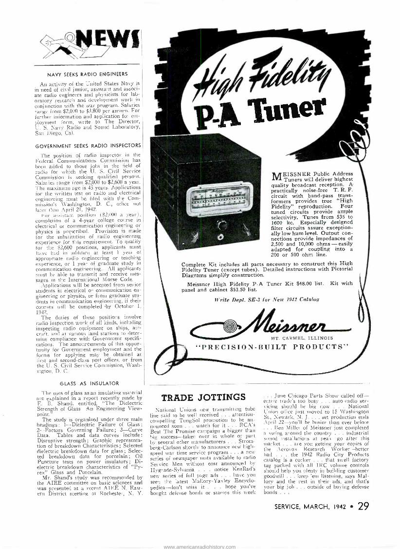
NAVY SEEKS RADIO ENGINEERS
An activity of the United States Navy is in need of civil junior, assistant and associ- ate radio engineers and physicists for lab- oratory research and development work in conjunction with the war program. Salaries range from $2,000 to $3,800 per annum. For further information and application for em- ployment form, write to The Director, U. S. Navy Radio and Sound l.ahoratory, San Diego, Cal.
GOVERNMENT SEEKS RADIO INSPECTORS
The position of radio inspector in the Federal Communications Commission has been added to those jobs in the field of radio for which the U. S. Civil Service Commission is seeking qualified persons. Salaries range from $2,000 to $2,600 a year. The maximum age is 45 years. Applications for the written test on radio and electrical engineering must be filed with the Com- mission's Washington, D. C., office not later than April 21, 1942.
ror assistant position ($2.000 a year), completion of a 4 -year college course in electrical or communication engineering or physics is prescribed. Provision is made for the substitution of radio engineering experience for this requirement. To qualify for the $2,600 positions, applicants must have had in additicn at least 1 year of appropriate radio engineering or teaching experience, or 1 year of graduate study in communication engineering. All applicants must be able to transmit and receive mes- sages in the International Morse Code.
Applications v. ill be accepted from senior students in electrical or communication en- gineering or physics, or from graduate stu- dents in communication engineering, if their courses will be completed by October 1,
1942. The duties of these positions involve
radio inspection work of all kinds, including inspecting radio equipment on ships, air- craft, and at carious land stations to deter- mine compliance with Government specifi- cations. The announcements of this oppor- tunity for Government employment and the forms for applying may be obtained at first and second-class post offices, or from the U. S. Civil Service Commission, Wash- ington, D. C.
GLASS AS INSULATOR
The uses of glass as an insulating material are explained in a report recently made by E. B. Shand, entitled, "The Dielectric Strength of Glass-An Engineering View- point."
The study is organized under three main headings : 1-Dielectric Failure of Glass ;
2-Factors Governing Failure; 3-Curve Data. Tables and data curves include: Disruptive strength ; Graphic representa- tion of breakdown Characteristics ; Selected dielectric breakdown data for glass ; Selec- ted breakdown data for porcelain ; Oil Puncture tests on power insulators ; Di- electric breakdown characteristics of "Py- rex" Glass and Porcelain.
Mr. Shand's study was recommended by the AIEE committee on basic sciences and was presented at a recent AIEE N. East- ern District meeting at Rochester, N. Y.
474 pp Tuner
MEISSNER Public Address Tuners will deliver highest
quality broadcast reception. A practically noise -free T. R. F. circuit with band-pass trans- formers provides true "High Fidelity" reproduction. Four tuned circuits provide ample selectivity. Tunes from 535 to 1600 kc. Especially designed filter circuits assure exception- ally low hum level. Output con- nections provide impedances of 2,500 and 10,000 ohms - easily adapted for coupling into a 200 or 500 ohm line.
Complete Kit includes all parts necessary to construct this High Fidelity Tuner (except tubes). Detailed instructions with Pictorial Diagrams simplify construction.
Meissner High Fidelity P -A Tuner Kit $48.00 list. Kit with panel and cabinet $53.50 list.
Write Dept. SE -3 for New 1942 Catalog
o / MT. CARMEL, ILLINOIS
"PRECISION -BUILT PRODUCTS"
TRADE JOTTINGS National Unions new transmitting tube
line said to be well received ... attention - compelling TungSol promotion to be an- nounced soon ... watch for it ... RCA's Beat The Promise campaign a bigger than big success-taken over in whole or part by several other manufacturers ... Strom- berg -Carlson shortly to announce new high- speed war time service program ... a new series of newspaper mats available to radio Service Men without cost announced by Hygrade-Sylvania . . . notice KenRad's new series of full page ads . . . have you seen the latest Mallory-Yaxley Encyclo- pediea-don't miss it . . . hope you've bought defense bonds or stamps this week
. June Chicago Parts Show called off- entire trade's too busy ... auto -radio ser- vicing should be big now . National Union office just moved to 15 Washington St., Newark, N. J.... set production ends April 22-you'll be busier than ever before ... Ben Miller of Meissner just completed a swing around the country ... industrial sound installations at peak-go after this market ... are you getting your copies of the Aerovox Research Worker-better had . the 1942 Radio City Products catalog is a corker . that swell factory tag packed with all IRC volume controls should help you plenty in building customer goodwill . keep 'em listening, says Mal- lory and the rest in their ads, and that's your big job ... outside of buying defense bonds . . .
SERVICE, MARCH, 1942 29
www.americanradiohistory.com

THIS is no time to take chances. When you have a
parts replacement to make in radio -phonograph or sound equipment, play safe and duplicate the model and make originally used by the manufacturer. Asiatic Cartridges, Recording Heads, Pickups and Microphones, available at your Radio Parts Jobber's, are products of the highest type, used by a great majority of America's leading manufacturers, and sure to give you long and dependable service. Keep your equipment up and fore- stall any possible replacement disappointments which might result from national emergency demands upon parts manufacturing facilities.
THE ASIATIC CORPORATION Licer.s:'. ','^:der Brush
Patents b `Y O U N G S T O W N, O H I U
Developmer Co. \ In Canada
Canadian Asiatic Ltd. Toronto, Ontario
EszPe-...e)
UNIVERSAL,
REPLACEMENT
Write for Catalog
SOLAR MFG. CORP., Bayonne, N. J.
30 SERVICE, MARCH, 1942
SERVICING QUESTIONS ANSWERED
$1.00 each (:Vo circuit diagram)
WILLARD MOODY 1923 16th St. N.W., Washington, D. C.
CATALOGS, Bul. I
Copies of the catalogs and bulletins discussed below may be obtained di- rectly from the respective manufac- turers mentioned. Write for them to- day!
Aerovox engineers are com- piling and releasing practical data on elec- tronic gadgeteering as a promising outlet for the equipment, skill and ambition of the Service Man. Articles on radio control cir- cuits and the industrial applications of elec- tronic devices, are currently appearing in the monthly Aerovox Research Worker. A free subscription may be obtained by getting the endorsement of any Aerovox jobber.
Allied Radio Corp., 833 W. Jackson Blvd., Chicago, III., announce the re- lease of their 1942 Spring and Summer cata- log, designed to supplement the 1942 Fall and Winter catalog by bringing prices up to date
and keeping pace with new developments. The new edition is a complete catalog in itself. A radio set section, covering 42 models, includes plastic and wood models, consoles, f -m combinations, auto -radio sets, farm re- ceivers, record players and recorders. A varied line of p -a and intercommunicating systems is illustrated. Also listed are parts, radio receiver kits, books and construction diagrams. A section on fluorescent lighting rounds out the booklet.
The Capacitor Manual for 1942 has been released by Cornell-Dubilier Electric Corp., South Plainfield, N. J. Here- tofore, it has been the practice to include in this mutual each year, all the replacement information from previous editions, plus data on new receivers. This year, the new manual takes the form of a supplement with provision for attaching directly to the cover of the 1941 Manual. With no more effort than that required to seal an envelope, the Service Man is thus enabled to convert his 1941 Manual into a 1942 edition so that in a single handy volume he has complete capacitor replace- ment data on all receivers up to and including current models, and a considerable saving in paper has been afforded. This 50 -page sup- plement adds information on approximately 2,000 receiver models, including not only ca- pacitor and voltage values and recommended replacement types, but filter and by-pass cir- cuits employed in each. Also given is the page number in Rider's Manuals where the complete circuit and other data for each of these receivers will be found.
An Air Raid Precautions direct mail folder and a poster is being made avail- able by Hygrade Sylvania Corp., 500 Fifth Ave., New York City. Eighteen precautions, vitally important to the protection of the public, are illustrated and set forth on the posters. They are printed in two colors, bright red and black. The Air Raid folders are avail- able for the cost of imprinting only. Size, flat, is 81/2" by 11". With every order of 250 or more, Sylvania gives a jumbo size blow-up, 17" by 22" for mounting in the window.
Hygrade Sylvania Corp., 500 Fifth Ave., New York City, announce a series of I and 2 column newspaper mats, available free to Sylvania Service Men. "Radios Need Inspection Too" is one of the themes that is illustrated, variously, with a delightful touch of humor. Others are handled in radio quiz form, telephone dial, dramatization of late news bulletin reception and that old folksy saying, "One Rotten Apple Will Spoil a Whole Barrel." Sylvania urges Service Men to promote their expert abilities aggressively, right now when new sets are disappearing from the market and the public can keep up their "radio contacts" only by having a Service Man repair broken down sets.
Lafayette Radio, 100 Sixth Ave., New York City, have issued a 4 -page rotogravure bulletin of specials in radio re- ceivers, parts and accessories for the busy Service Man.
Transmitting and Special Pur- pose Tubes is the title of an illustrated bro- chure from National Union Radio Corp., New- ark, N. J.
National Union Radio Corp., Newark, N. J., have released their latest re- ceiving tube characteristics chart. A feature of the new chart is a cross reference listing giving the RMA type numbers for Army tube types.
www.americanradiohistory.com
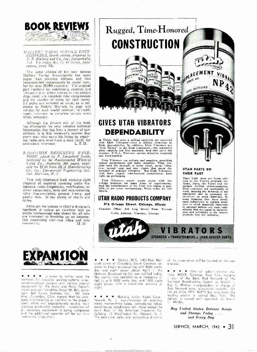
MALLORY RADIO SERVICE ENCY- CLOPEDIA, fourth edition, prepared by P. R. Mallory and Co., Inc., Indianapolis, Ind.. 415 pages. 8?/ by 10 inches, paper covers, price 95c.
The latest edition of the now famous Mallory Yaxley Encyclopedia has more pages than previous editions and lists recommended replacements by model num- ber for over 20,000 receivers. The original part numbers for condensers, controls and vibrators is an added feature in this edition. Also listed are complete tube complements and the number of tubes for each model. I -f peaks are included as usual, as is ref- erence to Rider's Manuals by page and volume for each model receiver, to enable ready reference to complete service notes when necessary.
Although the present size of the book has eliminated the very valuable technical information that has been a feature of past editions, it is this reviewer's opinion that every man who earns his living by repair- ing radio sets must have a copy handy for continuous reference. L. T. H.
RADIOTRO N DESIGNER'S HAND- BOOK, edited by F. Langsf ord Smith, published by the Amalgamated Wireless Valve Co., Australia, 365 Pages, avail- able for $1.00 from RCA Manufacturing Co., Inc., Commercial Engineering Sec- tion, Harrison, N. J. This well illustrated book contains eight
chapters of material covering audio fre- quencies, radio frequencies, rectification, re- ceiver components, tests and measurements, valve characteristics, general theory, and sundry data. It has plenty of charts and tables.
Although the volume is titled a designer's handbook it makes an excellent text on simple fundamental tube theory for all who are interested in brushing up on informa- tion concerning receiving tubes and tube functioning-. H. H.
In order to better meet the demands for industrial paging systems, inter- communications systems and various special equipment for the Army and Navy Depart- ments and war industries, Floyd W. Bell, presi- dent, Bell Sound Systems, Inc., 1183 Essex Ave., Columbus, Ohio, reports that his com- pany is completing an addition to the present plant which will approximately double their previous production capacity. Installation of all necessary equipment is being completed and the additional capacity will be put into immediate croduction.
Rugged, Time -Honored
CONSTRUCTION
GIVES UTAH VIBRATORS
DEPENDABILITY Today, well over a million receivers are equipped
with Utah Vibrators-over a million witnesses to Utah dependability. In addition, Utah Vibrators are "Life Tested" in the Utah Laboratory-the industry's most versatile and best equipped. And they carry the standarc R.M.A. Warranty against defective materials and workmanship.
Utah Vibrators are delicate and sensitive, providing utmost performance and radio reception. Then, too, they have the strength to resist shock, motor vibra- tion, normal wear and tear-rigors that cause the downfall of ordinary vibrators. But Utah Vibrators. with their rugged, time-honored construction, keep right on performing.
Utah Vibrators supply ample power with low voltage batteries for many types of requirements. And the completeness of the Utah line makes it pos- sible to get exact replacements. Write today for full details.
UTAH RADIO PRODUCTS COMPANY 816 Orleans Street, Chicago, Illinois
Canadian Office : 560 Fing Street West, Toronto Cable Address Utaradio, Chicago
AcEMENT VigR
Ptcg "°
et
UTAH PARTS DO THEIR PART Many Utah parts are being util- ized in the Victory program-for Army, Navy, Air Corps and im- portant civilian communications. Utah engineers are continually at work, meeting the demands of the emergency and its necessary re- strictions on some materials. In some instances they have devel- oped substitutes to replace prod- ucts in which materials important to national defense are used-sub- stitutes that are equal in perform- ance and reliability to the famous products they are replacing.
VIBRATORS PEAKERS TRANSFORMERS JTAH-CARTER P
Station WIS, NBC -Red Net- work outlet at Columbia, South Carolina, ex- pects to begin broadcasting with 5000 watts, day and night power about April I, the National Broadcasting Co. was notified today. The station now operates on a frequency of 560 kc wish 5000 watts day, and 1000 watts night power, with a directional antenna at night.
National Union Radio Corp., Newark, N. J., manufacturers of receiving tubes, transmitting tubes, cathode-ray tubes, panel lamps, condensers, etc., have leased the tenth floor of the American Insurance Co. Building, 15 Washington St., Newark, N. J. The execu-ive, sales and accounting divisions
of the corporation will be located at this new address.
One of radio's pioneer sta- tions, WSYR, Syracuse, New York, became a part of the Basic Red Network of the National Broadcasting System on March I, Roy C. Witmer, vice-president in charge of Red Network sales, announced recently. On +he air since 1923, WSYR has long been the leading station in central New York. The station is owned and operated by Harry C. Wilder.
Buy United States Defense Bonds and Stamps Today . . .
and Every Day
SERVICE, MARCH, 1942 31
www.americanradiohistory.com
ALWAYS
IN [INE
i
DEPEDDRBLE 40>'
IíEhRRot
o
SUPREME Every instrument scien- tifically engineered and soundly built for depend- able, accurate, profitable radio servicing. See your Jobber or write for new catalog.
SUPREME INSTRUMENTS CORP. MISS SSIIPPI
PERSONNEL
George F. Bartholomew, Jr., has been appointed an assistant director of production for Columbia Broadcasting System. A production man and writer for a major net- work for the last three years, Bartholomew is
a graduate of Yale University. While at Yale he was connected with the dramatic society and the Glee Club.
According to an announce- ment by B. R. Cummings, vice president in charge of engineering, Farnsworth Television and Radio Corp., F. B. Ostman is appointed as the company's Washington manager suc- ceeding W. A. Eaton who has resigned from the company to accept a commission as Lieutenant Commander in the U. S. Navy.
W. H. Green recently joined the General Electric radio and television de- partment, with the responsibility for planning and formulating, in conjunction with the pub- licity department, advertising and sales pro- motion for radio transmitting and carrier -cur- rent equipment, and transmitting, industrial, and special-purpose tubes. Mr. Green was assigned to industrial control advertising and sales promotion in June of 1941, and remained in this capacity until his recent transfer.
BOGEN keeps 'em rolling!
I
N defense plants throughout the country, Bogen Paging and Intercommunication sys-
tems are vital tools of production - because instant communication between any and all vital production points is the stuff that keeps things moving - "keeps 'em rolling." Bogen is building special Paging, Fire Alarm, Air Raid and Intercommunication Equipment to satisfy the varied requirements of different kinds of defense plants-A maximum of factory cooperation is aivailable on every such installa- tion - Write for details I I
DAVID BOGEN CO., Inc., 663 Broadway, New York City
WHEN YOU CHANGE YOUR ADDRESS
Be sure to notify the Subscription Department of SERVICE at 19 E. Forty-seventh St., New York
City, giving the old as wen as the new address,
and do this at least four weeks in advance. The
Post Office Department does not forward maga-
zines unless you pay additional postage, and we
cannot duplicate copies mailed to the old address.
We ask your cocperation.
D. C. Patrick, 1100 Colorado Blvd., Denver, Colo., has been appointed -lygrade Sylvania representative in the Denver territory for all of the company's products including Sylvania radio tubes, Hygrade fluorescent lamps, Miralume fluorescent fix- tures, fluorescent accessories and Hygrade incandescent lamps.
George K. Throckmorton, for the past five years president of the RCA Manufacturing Co., Inc., Camden, N. J., was recently elected chairman of the executive committee of that company. Robert Shannon, former executive vice president, was elected president. The promotion of RCA's two senior manufacturing executives was announced by David Sernoff, president of Radio Corp. of America and chairman of the board of RCA Manufacturing Co., Inc.
Appointment of the John W. Clarke Co., 327 S. LaSalle St., Chicago, Ill., as sales and engineering representatives for Dunco relays and timing devices has been an- nounced by sales manager Charles A. Packard, of Struthers Dunn, Inc., Philadelphia, Pa. Their territory includes the state of Wisconsin, the upper peninsula of Michigan; Northern Illinois; Chicago and the neighboring counties of Indiana and the Eastern border counties of Iowa.
Appointment of Walter C. Evans as general manager of three major Westinghouse divisions was announced by the
Westinghouse Electric and Manufacturing Cc. Each of the divisions has an individual man- ager, all three working under the direction of Mr. Evans. The divisions include radio, broad- casting and X-ray. Executive offices of the.
X-ray division have recently been moved to Baltimore, where the radio division has a large manufacturing plant. The broadcasting divisioi headquarters will remain in Philadelphia. Lea B. Wailes is manager of the broadcasting division; the X-ray division is headed by Clair V. Aggers; and Carrol J. Burnside, formerly sales manager of the radio division, is now manager.
Additional information and prices of the products described below may be obtained, without obligation, from the respectix'e manufacturers.
INTERCOMMUNICATOR
The Webster -Rauland Model \V105 is a low-cost intercommunicating system for office and industrial application. The sys- tem, manufactured by the Rauland Corp., 4245 N. Knox Ave_, Chicago, consists of a master, or central control unit, the only amplifier in the entire system, and up to five remote, or outlying substations can be used. The master or central unit can call
32 SERVICE, MARCH, 1942
www.americanradiohistory.com
UP TO THE MINUTE
ea& EDITION
WORTH HUNDREDS
OF DOLLARS TO YOU!
WeliA
e ee?1 d;sa,`.
v t+,
These Men Use GHIRARDI'S BOOKS
James R. Yates, Radio Electrician. 758th GHQ Tank Itart'e. declares: "Ghirardi's
Radio Physics is the finest hook ever written. It has helped me pass all the tests in the Armored Force School. The Army also uses the hook in its classes." . Read this from a service man. C. Paul T.auzon, Burlington, Vt.: "Words cannot express my - admiration for the RADIO TROTTBLE-SIIOOTER'S HANDBOOK I purchased from you. The information T received from page 397 and on. paid for the hook at least three tstnes over." . . Ghirardi's hooks are
prominently displayed at all leading jobbers. See for yourself that Ghirardi's books
are the "mist" on every service benc.
OTHER GHIRARDI TRAINING COURSES
Z9ff4v/?THE BIG ¡/O WARTIME
800/".1/ A
HANDBOOK YOU
CAN'T AFFORD
TO BE WITHOUT
7/04e :
of Brand NeW Dope
Monaal-ne4 W.9
ARE YOU UP TO YOUR NECK IN SERVICE WORK NOW? GHIRARDI'S RADIO TROUBLESHOOTER'S HANDBOOK can save you hours of servicing time every day and add to your profit! No matter how many servicing manuals you hate, you owe it to yourself to see this new revised 710 -page split-second reference handbook of bedrock working information. Complete and practical, all data is skillfully assembled, tabulated, boiled down to help you spot and clear up troubles easily, quickly, accurately. Trouble symptoms and remedies for over 46(Y) new and old models of home and auto sets and record changers: 66 other big sections of helpful servicing tables, chart. data, etc. Nothing else like it anywhere. Order a copy now.
* * * * OTHER GHIRARDI BOOKS START YOU FROM SCRATCH PREPARE YOU FOR QUICK ARMY AND NAVY PROMOTION!
Radio knowledge puts you in the money in the Army, Navy and in industry. Enlisted men get $21 monthly; radio men draw $72 a month; if married, $106.50. This is a day of specialists! Get the basic essentials and you can fill a dozen skilled, well -paid radio jobs. Don't waste time: do your part now: study in spare time to become an expert technician. After the war, FM. Television and Facsimile Radio transmission are certain to make radio the fastest growing industry. Ghirardi's famous RADIO PHYSICS Ghirardi'i MODERN RADIO SER - COURSE, selected as a training text VICI NG is the "Bible" of trained for the H. S. Army and Navy, packs into 972 pages the most Intensive, radio men. A complete 420 -page treat - easy -to -understand technical training ment of servicing instruments; tune
checking. how to test and repair Indi- vidual radin components, reduce elec- trical interference, align superneta; locate obscure troubles; etc. A $50 sett - study course for only 55. Special money- saving combination price: Modern Radio Servicing and Radio only8 Troubleshooter's Itundbook,
course In radio, sound. electricity and television. Designed for home study. no previous radio background needed. Here are the basic fundamentals you need no matter in what branch you specialize. Over 500 photographs and diagrams. 856 special self -review questions help you check every step of your progress. The course only $5 complete in one volume--
RADIO & TECHNICAL PUBLISHING CO., Dept. S-32 45 ASTOR PLACE, NEW YORK, N. Y.
and converse with any one of the five re- mote stations as selected. A feature of this system is that the master unit can call and "listen -in" or converse with all five remote stations at one time. Tais is done by means of the sixth or "all" position on the selector switch.
Manufactured by The Rauland Corpora- tion, 4245 No. Knox Avenue, Chicago, Illi- nois.
MICA CAPACITORS Solar Manufacturing Corp., Bayonne,
N. J., present a series of moulded bakelite mica condensers of compact size for use
in receiving tube and electronic circuits. Known as types MK and ML, the con-' densers are available in a wide variety of sizes and voltage ratings.
DUAL AMPLIFIER Bogen Model E75 is a dual amplifier
featuring two 35 -watt units each equipped with its own power supply, rectifier cir- cuits, filter circuits and output channels. The connections and controls are such that
the amplifier can be used as a 35 -watt unit or the outputs can be paralleled to deliver 70 -watts. Three input channels, bass - treble tone control, inverse feedback and
tapped output transformers are among the features of this high-powered amplifier. David Bogen, Inc., 663 Broadway, New York City.
CASE HISTORIES o o
PHILCO 42-842, 42-843, 42-844, 42-853, 42-854
Filament resistor change: In the above listed models, complaints may be re- ceived of a complete set of tubes testing weak. Replacement of the tubes restores normal operation for only a short time after which the same condition re- occurs.
The condition is caused by the over- heating of the 1800 -ohm series filament resistor shown as No. 49 in service bul- letin 391 and as No. 56 in service bul- letin 388. When the overheating takes place, the resistor breaks down, its re- sistance value decreases, thus allowing an increased filament current to the tubes with resulting damage to filaments.
It is recommended that an entirely new replacement resistor of the 10 -watt wire -wound type he used. The resistor
can be mounted vertically over one of the original holes in the chassis with a suitable drive screw. The longer leads which are required for the installation must be fireproof and not ordinary rub- ber covered type. They can be brought down through the large hole in the re- ceiver chassis.
RCA QU7, QU51, QU52, QU55, QU56
Tone arne pressure spring: When re- placing the tone arm, or the magnetic pickup head, check the needle pressure which should lie approximately 3 ounces. Alter the counter -balance spring in the arm to obtain the correct pressure, or install a new spring. Two springs (65 turns and 75 turns) are available. Use the spring that most nearly gives the correct pressure and then remove turns, or stretch the spring as required.
SERVICE, MARCH, 1942 33
www.americanradiohistory.com

4 STANDARD TYPES of Amperite Regulators replace over 400 types of AC -DC Ballast Tubes now in use.
Amperites are real REGULATORS ... have patented Automatic Starting Resistor whi
events initial surge and saves pilot lígo
... Ask Your Jobber.
THE "Sr
WAY TO REPLACE
BIILLII5T5 WRITE FOR REPLACEMENT CHART
AMPER/TECO $N BROADWAY. NEW 0055. N r
MODEL 432-A
The Outstanding Tube Tester Value . .
Checks all type tubes including Loctals. Bantam Jr., 1.4 volt Miniatures, Gaseous Rectifier, Ballast, High Voltage Series, etc. Filament Voltages from 1.1 to 110 volts. Direct Reading GOOD -BAD Meter Scale. Professional -appearing case with accessory compartment large enough for carrying Model 739 AC -DC Pocket Volt-Ohm-Milliam- meter, thereby giving the serviceman complete testing facilities for calls in the field Model 432-A with compartment, Dealer Net Price . . . . $20.73.. Model 432-A in case less compartment . . . . $19.65. Model 739. Dealer Net Price . . . . $10.89.
WRITE OR CATALOG-Section 317. College Drive
READRITE METER WORKS, Bluffton, Ohio
34 SERVICE, MARCH, 1942
Index of Advertisers
Page A
Aerovox Corp. 26 Amperite Co. 34 Astatic Corp., The 30
B
Bogen Co., Inc., David 3'
C
Centralab 4 Clarostat Mfg. Co., Inc 28
E
Everett d}- Mini -Ma x Batl,ri,' 15
II
Hygrade Sylvania Corp 24
s
Iíen-Rad Tube & Lamp Corp. 1 32
Mallory & Co., Inc., P. R.. Inside Front Cover
Meissner Mfg. Co 29
N
National Carbon Co., Inc. 15 National Union Radio Corp 17
R
Radfart Corp.. The 20, 21 Radio & Technical Publishing Co..... 33 Radio City Products Co.. Inc.
Inside Rack Cover RCA Mfg. Co., Inc Rack Cover Readrite Meter Works 28 Rider Publisher, Inc., John F 27
Solar Mfg. Corp 30 Sprague Products Co 25 Supreme Instruments Corp 32
T
Triplett Elec. Inst. Co.. The 3
Union Carbide & Carbon Corp 15 United Catalog Publishers, Inc 34 United Transformer Co 18 Utah Radio Products Co 31
Y
Yaxley Mfg. Division Inside Front Cover
»dice MASTER ENCYCLOPEDIA
J"' REFERENCE I
BOOK 1 51 t»
BUYING GUIDE
SALES CATALOG
ENCYCLOPEDIA
9th EDITION OVER 800 PACES
THE ONLY OFFICIAL RADIO PARTS AND EQUIPMENT MANUAL
It took six years and thousands of dollars to develop this "MASTER CATALOG" of the radio industry to its present size-yet it costs you only $2.50.
Compiled in co-operation with and approved by the Radio Manufacturers Group as the in- dustry's official source book.
GIVES THIS IMPORTANT DATA
Contained within the hard covers of this 800 page MASTER BOOK are the listings of the products of 90% of all Radio Parts and Equip- ment Manufacturers in the industry. In it you will find many thousands of items, such as elec- tronic devices, transmitting and receiving sets, tubes, antennas, transformers, condensers, re- placement parts, meters, laboratory test equip- ment, relays, plugs, coils, wire, and numerous other radio components. Thousands of clear illustrations with descriptions and specifications. -Yes, this is your "MUST HAVE BOOK".
WHO USES IT? As the official source hook of the radio industry it is constantly used by many American and Foreign governmental agencies, also industrial organizations, engineers, purchasing agents, lab- oratories, radio amateurs and service men, radio distributors, broadcast stations, schools, colleges, libraries, and by many others interested in Radio and allied fields.
SAVES TIME-SAVES MONEY WHERE, WHAT AND HOW MUCH: Such information is instantly at your fingertips. This Valuable RADIO MASTER eliminates the main- tenance of bulky files. It is completely indexed for speedy reference.
If you buy, sell or specify you will find the RADIO MASTER an indispensable and handy book to have around at all times.
MONEY BACK GUARANTEE!
Order your copy today-look it over. You will find it to be an excellent investment; if not, return it to us in five days for full refund.
The price is only $2.50 shipped anywhere in U.S.A.-$3.00 elsewhere. We prepay transpor- tation charges if remittance accompanies order.
UNITED CATALOG PUBLISHERS, Inc. 106A Lafayette St. New York, N. Y.
www.americanradiohistory.com
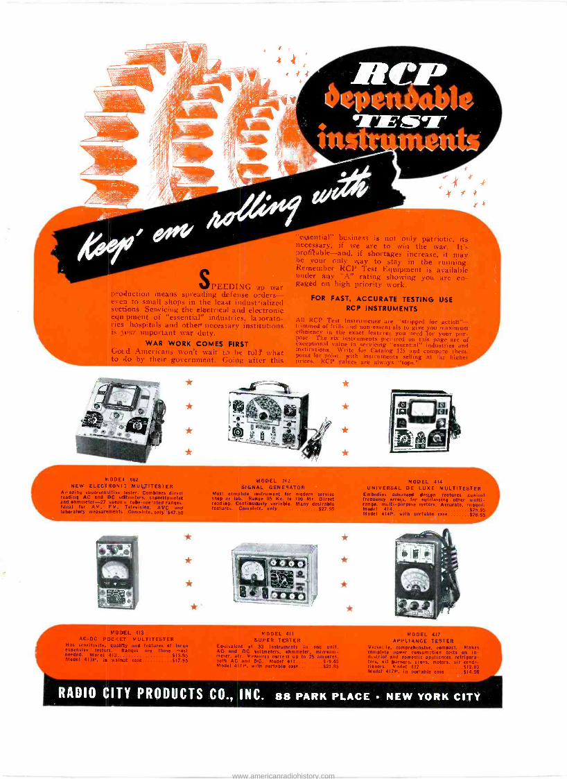
SPEEDING up war production means spreading defense o.-ders- even to small shops in the least indust-ialized sections. Servicing the electrical and electronic tqu pillent of "essential" industries. la )orato- Vies hospitals and other necessary institutions is _tour important tsar duty.
WAR WORK COMES FIRST Gotd _Americans won't wait t: he told what to .lo by their government. Going after this
MODEL 662 NEW ELECTRONIC MULTITESTER
Amazing supersensitive tester. Combines direct reading AC and DC voltmeters, capacitymeter and ohmmeter -27 vacuu n tube -operated ranges. Ideal for AM. FM. Television. AVC and laboratory measurements Complete. only $47.50
413 AC -DC POCK MULTITESTER
Has sensitivity, quality and features of large expensive testers. Ranges are those most needed. Model 413 $15.95 Model 413P, in walnut case $17.95
f
"essential" business is not only patriotic, its necessary, if we are to win the war. It's profitable-and, if shortages increase, it may, be your only way to stay in the running? Remember RCP Test Equipment is available under any "A" rating showing von are en- gaged on high priority work.
FOR FAST, ACCURATE TESTING USE RCP INSTRUMENTS
All RCP Test 'Instruments sire "stripped for action"- trimmed of frills and non -essentials to give you maximum efficiency in the exact features you need for your pur- pose. The six instruments pictured on this page are of exceptional value in servicing "essential" industries and institutions. Write for Catalog 125 and compare them. point -for -point, with instruments selling at ta. higher I eiees. RCP values are beat's "tops.'
X
11111111111111r- (MODEL 712 SIGNAL GENERATOR
Most complete instrument for modern service shop or lab. Range 95 Kc. to 100 Mc. Direct readi ig. Continuously,. Many desirable features. x,93
MODEL 411
SUPER TESTER Equivalent of 33 instruments in one unit. AC and DC voltmeters, ohmmeter. microarn- me*er, etc. Measures curre It up to 25 amperes. both AC and DC. Model 411 $19.45 Model 411P, with portable case $21.95
X
*
*
7r
MODEL 414 UNIVERSAL DE LUXE MULTITESTER
Embodies advanced design features against frequency errors. far outclassing other multi - range, multi -purpose meters. Accurate, rugged. Model 414 $25.95 Model 414P. with portable case $28.95
MODEL 417 APPLIANCE TESTER
Versatile. comprehensive, compact. Makes complete power consumption tests on in- dustrial and domestic appliances, refrigera- tors, oil burners. signs, motors. air condi- tioners. Model 417 $12.95 Model 417P. in portable case $14.95
RADIO CITY PRODUCTS CO., INC. 88 PARK PLACE NEW YORK CITY
www.americanradiohistory.com

Solid Walnut Cabinet 5" Electrodynamic Speaker 5 RCA Preferred Type Tubes Built-in Tuned Loop Gets Police Calls Superhet with AVC Large, Clear -Vision Dial
The New RADIOL4 Model 522 with SOLID WALNUT Cabinet!
Here's the latest addition to the great line of radios for servicemen to sell
-a Radiola in a genuine solid walnut cabinet, beautifully shaped and fin-
ished! Take one along on your next service call, for extra business and extra profits. Features like these make it easy to sell:
Extra -large, high -Q, built-in tuned loop antenna brings in even weak sig-
nals with surprising strength. In all
but a few locations, there's no need
for any other antenna. Your custom- ers can carry this extra set from room
to room-just plug it in and turn it on. There's an extra antenna -connec-
tion, too, for areas where signals are unusually weak ... or for customers who like outstanding DX reception.
Best of all, the 522 costs no more
than most sets-yet carries a full margin of profit for you. See your RCA Tube and Equipment Distrib- utor today.
All Radiola Models are Exclusively Equipped with RCA Preferred Type Tubes
Radiola Model 520 For your service customers who are looking for plenty of radio value at rock -bottom cost- try the new Radiola 520! Solid wood cabinet, covered with choice walnut veneers, houses a five -tube superhet chassis with plenty of sensitivity and performance. Full -toned elec- trodynamic speaker and reserve -power audio system yield outstanding tonal performance, amazing in so compact a receiver!
R.ac.Iiolct PREFERRED TYPE RADIOS Made by RCA Manufacturing Company, Inc., Camden, N. J.
www.americanradiohistory.com


![Louie’s Hungry Five: The Radio Work of Henry Moeller and ...s Hungry Five.pdf7 Radio Digest confirms that “last October [1930] Moeller and Gilles [Herr Louie and the Weasel, respectively]](https://static.fdocuments.in/doc/165x107/5f59a37d7dde4c6aac24789a/louieas-hungry-five-the-radio-work-of-henry-moeller-and-s-hungry-fivepdf.jpg)