Diffraction analysis by periodic structures using a …4)331.pdfDiffraction analysis by periodic...
10
Diffraction analysis by periodic structures using a method of coupled waves V.M. FITIO *1 and Y.V. BOBITSKI 1,2 1 Lviv Polytechnic National University, 12 Bandera Str., 79013 Lviv, Ukraine, 2 Institute of Technology, University of Rzeszów, 16a Rejtana Str., 35-959 Rzeszów, Poland The coupled-wave method (CWM) has been used to analyse diffraction on some periodic structures, i.e., on relief gratings including metallized ones having sinusoidal relief as well as on one-dimensional and two-dimensional photonic crystals. Exact boundary conditions were taken into account in numerical calculations. Grating polarizers have been analysed, prop- erties of dielectric gratings wherein coupled-mode resonance occurs have been studied, diffraction efficiency has been cal- culated for sinusoidal relief metallized gratings. Calculations were carried out for TE and TM polarizations. Band structure of a two-dimensional photonic crystal has been calculated using CWM. Keywords: grating, diffraction, coupled-wave resonance, photonic crystal. 1. Introduction There is a great number of papers and monographs devoted to the study of light propagation in periodic structures (volume gratings, interference mirrors, photonic crystals, thin holo- grams, relief gratings including relief gratings on metal). Among them there are two monographs that can be men- tioned here, one concerning volume gratings [1] and the other concerning photonic crystals [2]. The monograph [1] summa- rized the results of theoretical and experimental studies of vol- ume gratings by means of approximation methods and the main attention has been focused on TE-polarization wave dif- fraction. Kogelniks paper [3] that dealt with all types of vol- ume holograms and yielded good results, when the modula- tion factor of dielectric constant of a periodic medium is much less than one (<< 1), was the most characteristic and popular work of that time. However, approximation methods are not suitable to analyse periodic structures having significant mod- ulation factors of dielectric constant. Therefore accurate sys- tems of equations were obtained and accurate initial condi- tions were defined using the Bloch-Floquets theorem based on Maxwells equations [4]. One can deem that the exact the- ory of diffraction on volume gratings [5], interference mirrors [6], and relief gratings [7,8] has received completion in the works by Moharam and Gaylord. These works have not re- ceived wide publicity since the solution of the system of dif- ferential equations can be only obtained using powerful com- puters which were not available to the wide community of scientists and engineers in the 1980s. In general, those calcu- lation methods were called the coupled-wave methods (CWM). An interest in exact solutions of diffraction problems by means of numerical methods appeared in the 1990s when high-speed PCs became reality. The modal method by Fourier expansion and the modal method by modal expansion were developed [9]. In these methods, an infinite dimensional sys- tem of linear differential equations with constant or variable coefficients can be obtained on the basis of Maxwells equa- tions and the difference between them is due to exact bound- ary conditions being taken into account using different tech- niques. Therefore, these methods are considered to be identi- cal and are called depending on the author of a paper either CWM [10] or the Fourier expansion methods [11]. In Refs. 12 and 13, the systems of first-order linear differential equa- tions are formulated that are identical to the equations given in Ref. 11 but which are obtained by a way of variable ampli- tude plane wave expansion of the electromagnetic field. The Bloch-Floquets theorem is not used to obtain these equations and, therefore, we believe that this method is more universal and can be used in other problems. The initial conditions are used in a different way and we suppose that this approach is simpler and clearer than the approaches of other authors [10,14–17]. Whereas there are no particular problems when studying diffraction of TM-polarized light on periodic struc- tures using CWM (even for the case of metallized gratings), it is necessary to take into account a great number of diffraction orders because of slow convergence in order to make an exact calculation. In order to improve convergence (in order to get the desired calculation accuracy one should use a system of differential equations of the least possible dimension) for TM-polarized waves a little modified system of equations was proposed in Refs. 15, 16, 17, and 18, which has been obtained using Fourier expansion of permittivity and its reciprocal. A strict mathematical substantiation for such modification of the system of equations for TM-polarized light diffraction is Opto-Electron. Rev., 13, no. 4, 2005 V.M. Fitio 331 Regular Issue Papers OPTO-ELECTRONICS REVIEW 13(4), 331–339 * e-mail: [email protected]
Transcript of Diffraction analysis by periodic structures using a …4)331.pdfDiffraction analysis by periodic...

Diffraction analysis by periodic structures using a methodof coupled waves
V.M. FITIO*1 and Y.V. BOBITSKI1,2
1Lviv Polytechnic National University, 12 Bandera Str., 79013 Lviv, Ukraine,2Institute of Technology, University of Rzeszów, 16a Rejtana Str., 35-959 Rzeszów, Poland
The coupled-wave method (CWM) has been used to analyse diffraction on some periodic structures, i.e., on relief gratings
including metallized ones having sinusoidal relief as well as on one-dimensional and two-dimensional photonic crystals.
Exact boundary conditions were taken into account in numerical calculations. Grating polarizers have been analysed, prop-
erties of dielectric gratings wherein coupled-mode resonance occurs have been studied, diffraction efficiency has been cal-
culated for sinusoidal relief metallized gratings. Calculations were carried out for TE and TM polarizations. Band structure
of a two-dimensional photonic crystal has been calculated using CWM.
Keywords: grating, diffraction, coupled-wave resonance, photonic crystal.
1. Introduction
There is a great number of papers and monographs devoted to
the study of light propagation in periodic structures (volume
gratings, interference mirrors, photonic crystals, thin holo-
grams, relief gratings including relief gratings on metal).
Among them there are two monographs that can be men-
tioned here, one concerning volume gratings [1] and the other
concerning photonic crystals [2]. The monograph [1] summa-
rized the results of theoretical and experimental studies of vol-
ume gratings by means of approximation methods and the
main attention has been focused on TE-polarization wave dif-
fraction. Kogelniks paper [3] that dealt with all types of vol-
ume holograms and yielded good results, when the modula-
tion factor of dielectric constant of a periodic medium is much
less than one (<< 1), was the most characteristic and popular
work of that time. However, approximation methods are not
suitable to analyse periodic structures having significant mod-
ulation factors of dielectric constant. Therefore accurate sys-
tems of equations were obtained and accurate initial condi-
tions were defined using the Bloch-Floquets theorem based
on Maxwells equations [4]. One can deem that the exact the-
ory of diffraction on volume gratings [5], interference mirrors
[6], and relief gratings [7,8] has received completion in the
works by Moharam and Gaylord. These works have not re-
ceived wide publicity since the solution of the system of dif-
ferential equations can be only obtained using powerful com-
puters which were not available to the wide community of
scientists and engineers in the 1980s. In general, those calcu-
lation methods were called the coupled-wave methods
(CWM). An interest in exact solutions of diffraction problems
by means of numerical methods appeared in the 1990s when
high-speed PCs became reality. The modal method by Fourier
expansion and the modal method by modal expansion were
developed [9]. In these methods, an infinite dimensional sys-
tem of linear differential equations with constant or variable
coefficients can be obtained on the basis of Maxwells equa-
tions and the difference between them is due to exact bound-
ary conditions being taken into account using different tech-
niques. Therefore, these methods are considered to be identi-
cal and are called depending on the author of a paper either
CWM [10] or the Fourier expansion methods [11]. In Refs.
12 and 13, the systems of first-order linear differential equa-
tions are formulated that are identical to the equations given
in Ref. 11 but which are obtained by a way of variable ampli-
tude plane wave expansion of the electromagnetic field. The
Bloch-Floquets theorem is not used to obtain these equations
and, therefore, we believe that this method is more universal
and can be used in other problems. The initial conditions are
used in a different way and we suppose that this approach is
simpler and clearer than the approaches of other authors
[10,14–17]. Whereas there are no particular problems when
studying diffraction of TM-polarized light on periodic struc-
tures using CWM (even for the case of metallized gratings), it
is necessary to take into account a great number of diffraction
orders because of slow convergence in order to make an exact
calculation. In order to improve convergence (in order to get
the desired calculation accuracy one should use a system of
differential equations of the least possible dimension) for
TM-polarized waves a little modified system of equations was
proposed in Refs. 15, 16, 17, and 18, which has been obtained
using Fourier expansion of permittivity and its reciprocal. A
strict mathematical substantiation for such modification of the
system of equations for TM-polarized light diffraction is
Opto-Electron. Rev., 13, no. 4, 2005 V.M. Fitio 331
Regular Issue Papers
OPTO-ELECTRONICS REVIEW 13(4), 331–339
*e-mail: [email protected]

given in Ref. 11. A special attention should be given to Ref.
18 where the system of differential equations was obtained
which provides rapid convergence of solution for relief grat-
ings including the metallized ones for the case of TM-polari-
zation. The C-method or coordinate transformation method
was proposed to accelerate the analysis of TM-polarized light
diffraction for metallized relief gratings (e.g., with a sinusoi-
dal profile) [19,20]. All those methods are based on numerical
solution of the system of differential equations that can take
into account hundreds of diffraction orders. It is possible to
say that at the moment there are efficient methods to analyse
diffraction of light on various periodic structures, and these
methods are used to design various optical devices such as
polarizers with periodic arrangement of metallic bands [21],
narrow-band optical filters on the basis of coupled mode reso-
nance [22–26], and diffraction relief gratings [27]. Analysis of
diffraction gratings using CWM foresees that the periodic
structure is boundless in two directions, and in the third direc-
tion it is bounded by two parallel planes, the media beyond
the grating are homogeneous, and the boundary conditions are
defined from the continuity of the tangential components of
the strength of electric and magnetic fields on the planes that
bound the grating. For analysis of photonic crystals it is fore-
seen that they are extended to infinity in three dimensions and
permittivity may depend periodically from one, two and three
variables (one-dimensional, two-dimensional or three-dimen-
sional photonic crystals, respectively) [2]. In this case, a tradi-
tional analysis consists in solving of wave equation relative to
the magnetic field strength, the solution is reduced to eigen-
values, and, for instance, a matrix equation with dimensions
of more than 1000´1000 is used to analyse a three-dimen-
sional photonic crystal [28,29]. After finding a solution, the
frequencies of electromagnetic waves that can propagate in a
photonic crystal with the given value of the wave vector are
defined. It is obvious that high-speed computers are needed to
solve such problems. But even in this case the calculation ac-
curacy is low. On the other hand, when the coupled wave
equations [11–13] is carefully examined, one can conclude
that these equations can also describe the propagation of al-
lowed electromagnetic waves in a boundless photonic crystal
with periodic initial conditions.
Thus, the purpose of this work is as follows: to formu-
late the initial conditions for solving the diffraction prob-
lems and to show the efficiency of analysing various types
of diffraction gratings using our method [12,13], to find
methods of rapid search for submatrices of fundamental so-
lution matrix using spatial symmetry of the diffraction
problem, to show that it is possible to calculate the band
structure of one-dimensional and two-dimensional photo-
nic crystals using the CWM, and to for analysis of one-di-
mensional photonic crystals it is sufficient to solve a sys-
tem of two first-order differential equations (exact solu-
tion), and for two-dimensional photonic crystals it is neces-
sary to solve a truncated system consisting of the 2n
first-order differential equations that is equivalent to a sys-
tem of n2 in the traditional method [2].
2. A system of differential equations fora diffraction grating. Initial conditions
A generalized diffraction grating is shown in Fig. 1. The
grating has the thickness d in the direction of z-axis and is
boundless in the xoy plane; its permittivity varies periodi-
cally along the x-axis with period L and can be also de-
pendent on z (e.g., for a sinusoidal relief grating). The first
medium that fills the whole space above grating (z < 0) has
permittivity e1, it is real and more than zero, the second
medium (grating) has dielectric constant e2(x,z) and can be
a complex quantity, and the third medium (z > 0) is charac-
terized with the constant e3.
In the first medium, in xoz plane, a plane wave falls
onto the grating at the angle q10 to z-axis. As a result of
light diffraction in the grating, secondary plane waves with
the amplitudes Rn (reflection amplitudes) propagate in the
first medium, and waves with the amplitudes Tn (transmis-
sion amplitudes) propagate in the third medium. The initial
equations [30] in the partial derivatives which are used to
obtain common linear systems of differential equations
[31] that describe diffraction on periodic structures are as
follows
rot
rot
E H
H E
= -
= -
jc
j x zc
w
ew
2 ( , )
(1)
where E, H are the electric and magnetic vectors of elec-
tromagnetic field, respectively, c is the velocity of light in a
vacuum, w = k c0 is the cyclic frequency, k 0 2= p l, and
l is the wavelength in a vacuum.
Besides, the permittivity of the second medium and its
reciprocal are expanded into complex Fourier series with
the following coefficients
e ep
p z x z i px dx( ) ( , )exp= -æèç
öø÷ò
1 22
0L L
L, (2)
a zx z
i px dxp ( )( , )
exp= -æèç
öø÷ò
1 1 2
20L L
L
ep
. (3)
Diffraction analysis by periodic structures using a method of coupled waves
332 Opto-Electron. Rev., 13, no. 4, 2005 © 2005 COSiW SEP, Warsaw
Fig. 1. A generalized diffraction grating e e( , ) ( , )x z x z= + L .

2.1. Equations and initial conditions forTE-polarization
It is expedient to expand the electric and magnetic fields as
follows [12]
E e
H e e
( , ) ( )exp( )
( , ) [ ( )
x z G z jk x
x z F z F
y nn
nx
x nx z nz
= -
= - +
å( )]exp( )z jk x
nnxå -
(4)
where ex, ey, ez are the unit vectors along x, y, and z are the
axes, respectively, Gn(z) is the electric field of a coupled
wave having index n, Fnx(z), Fnz(z) are the x and z compo-
nents of the magnetic field of a coupled wave having the
index n.
The wave vector knx is related to the wave vector k0x as
follows
k k nnx x= -0
2pL
, (5)
where k x0 1 102= ( ) sinp e l q and n is the integer.
Substituting Eq. (4) into Eq. (1), taking into account
Eqs. (2) and (5), and equalizing coefficients before each
factor exp jn x2pL
æèç
öø÷ to zero we obtain the following system
of differential equations
& ( ) ( ),
& ( ) ( ) ( ) (
G z jk F z
F z jk
kG z jk z G
n n
nnx
n np p
= -
= -
0
2
00 2e z
p
).å(6)
Since the system of Eq. (6) contains the first derivatives
Gn and Fnx and a simple algebraic relationship exists be-
tween Gn and Fnz(k G k Fnk n nz= 0 ), we can exclude Fnz
from the system of equations and omit the lower index x in
Fnx. In a general case, n varies from –¥ tn +¥. In a certain
case of calculations, we must restrict ourselves to a finite
dimensional system, i.e., we must take into account N dif-
fraction orders, and as result we shall have system Eq. (6)
of 2N equations. The number of diffraction orders deter-
mines the calculation accuracy.
The system of differential equations, Eq. (6), can be
written as a matrix
&
&
G
F
0 B
B 0
G
F
æèç
öø÷ =
æèç
öø÷æèç
öø÷
1
2
, (7)
where B I1 0= - jk , B20
20 2
1= -j
kk jk
n npe , I is the
unit matrix, kn
2is the diagonal matrix whose elements are
equal to knx2 . e 2 np
is the Toeplitz matrix formed from
Fourier expansion coefficients e n z( ) in conformity with the
rule
e
e e ee e e
e
2
0 1
1 0 1
np
N
N
N
z z z
z z z
z
= - -
-
( ) ( ) ( )
( ) ( ) ( )
( )
K
K
K K K K
e e- +N z z1 0( ) ( )K
.
It should be noted here that matrices B1 and B2 are con-
nected one with other.
In accordance with Ref. 31, the solution of the system
of Eq. (7), may be represented as
G
F
G
F
A A
A A
G( )
( )
( )
( )
z
zA
æèç
öø÷
=æèç
öø÷
=æèç
öø÷
0
0
11 12
21 22
( )
( )
0
0F
æèç
öø÷, (8)
where the matrix A is the solution of a corresponding ma-
trix Eq. (7) in the interval [0, z] for initial unit matrix in the
point z = 0. Since the matrix trace in Eq. (7) is zero, det(A)
= 1 accordingly to Ref. 31. This result may be used effi-
ciently to monitor the accuracy of calculation. If the dielec-
tric constant of periodic medium does not depend on z, the
following relation is valid
A z z z( ) exp exp( )=æèç
öø÷
é
ëê
ù
ûú =
0
0
1
2
B
BB . (9)
Thus, accordingly to Eq. (8) we may write the follow-
ing matrix equations
G A G A F
F A G A F
( ) ( ) ( ),
( ) ( ) ( )
d
d
= += +
11 12
21 22
0 0
0 0(10)
Completing algebraic system of Eq. (10) with a supple-
mentary system of equations that follow from the equality
of the tangential components of the electric and magnetic
field at the boundaries (z = 0 i z = d) of the periodic and ho-
mogeneous media, we may uniquely calculate Rn and Tn.
The wave amplitudes Rn and Tn of corresponding diffrac-
tion orders, which propagate into the first and third media,
we will regulate and write in the vectorial form R and T.
The algebraic systems of equations that arise from the con-
ditions at the boundaries are in vector form as follows [13]
R G V
C R F C V
T G
C T F
- = -- = -
- =- =
( )
( )
( )
( )
0
0
0
0
1 1
3
d
d
(11)
where V is the column vector whose components are equal
to Vn n= d 0 , i.e., to Kroneckers symbol when one index is
zero, C1 and C3 are the diagonal matrices whose elements
are equal to C n n1 1 1= e qcos and C n n3 3 3= e qcos , re-
spectively.
Cosines of propagation angles of diffracted wave in the
first and the third media can be expressed using corre-
sponding sines as follows
cos sinq q12
1 1n nj= -
cos sinq q32
3 1n nj= - -
Opto-Electron. Rev., 13, no. 4, 2005 V.M. Fitio 333
Regular Issue Papers
This notation enables selection of proper signs before
the cosines even when the propagated waves in the first and
the third media are damped waves (sin q1 1n > , sin q3 1n > ).
Using Eqs. (10) and (11) we can find all the unknown vec-
tors
F C A C C A A C A
A C A V
( ) ( )
( )
0 2 3 11 11
3 12 21 11
221
21 3 11
= + - -´ -
- - -
,
( ) ( ) ,
( ) , ( )
G C F V
R G V T G
0 0 2
0
11= +
= - =
-
d
(12)
Thus, in accordance with Eq. (12), knowing the subma-
trices A11, A12, A21, A22 of the matrix A(d) one can calcu-
late the amplitudes of all diffracted plane waves in the first
and the third media by means of matrix algebra and, conse-
quently, to determine diffraction efficiencies of all diffrac-
tion orders. The most complex problem for computer-aided
calculations is finding the matrix A(d), which, for the case
when the dielectric constant e2 does not depend on coordi-
nate z, is reduced to finding the proper numbers and proper
vectors of a matrix from Eq. (7), whose dimension is 2N ´2N, where N is the number of diffraction orders taken into
account. The situation is a little bit simplified when the sys-
tem of the first-order, Eq. (7), is reduced to a system of the
second-order equations, however, with the dimension N.
These systems which are equivalent will be as follows
&&
&&
F B B F
G B B G
=
=2 1
1 2
,(13)
When eigenvalues of the matrix B1B2 which are equal
to g n2 and the corresponding eigenvectors that form matrix
S are found, the solution of Eq. (13) may be written as
G A C A C
F A C
( ) exp( ) exp( ) ,
( ) exp( ) exp
z z z
z z
g g
f
= + -
= ++ -
+
1 1
1 ( ) ,- -A C1z f
(14)
where Cg+, Cg–, Cf+, Cf–, are the vectors that are related to
integration constants and are determined byF(0) and G(0).
The matrix A1 can be calculated as follows: A1 =
SGS–1, where G is the diagonal matrix formed on the basis
of array of eigenvalues g gn n= 2 . If Cg+ , Cg- , C f + ,
C f - , are determined from the condition when z = 0 and
Eqs. (8) and (14) are compared, the following relations can
be written
A A A A
A A
1
1
1 22 1 1
2 1
1
2
1
2
= = + -
= -
[exp( ) exp( )],
[exp( ) exp
z z
z ( )]
[exp( ) exp( )]
-
= - -
-
-
A A B
A A A AB
11
1
1 1 1 111
2
z
z z2
(15)
where exp( ) exp( )± = ± -A S S11
z zG .
Between the submatrices A11, A12 , A21, A22 , the fol-
lowing relation is valid
A A A A I11 22 12 21- = , (16)
that can be used to monitor the accuracy of calculation.
Thus, the finding of eigenvalues and eigenvectors of the
matrix B1B2 is the most cumbersome operation in calculat-
ing of R and T vectors. All the other calculations take sub-
stantially less time. We believe that this procedure is suffi-
ciently clear and rational.
The situation becomes more complicated when the di-
electric constant of the second medium depends on z (e.g.,
in relief gratings with sinusoidal relief). In this case, the
whole grating thickness d is divided into r layers, the thick-
ness of each layer being h d r= [5], and r can be more than
50. Within each layer we solve Eqs. (7) or (13) using the
matrix algebra methods, and after that we match the solu-
tions at the layer boundaries and between the grating and
the homogeneous media. In this case, it is necessary to
solve a linear algebraic system of equations where the
number of unknown values are N r[ ( )]6 4 1+ - . In other
words, the problem becomes rather cumbersome, espe-
cially for TM polarization. Therefore, a little bit different
algorithm is proposed to solve such problems. The matrix
A(d) for the grating can be represented as the product of
matrices of the corresponding layers
A A A
A A
( ) [ , ( ) ] [ , ( ) ]
( , ) [ , (
d h r h h r h
h h h m
@ - - -
= -
1 2 1 1 2
2 1 2
K
K ) ]h
m
r
=Õ
1
. (17)
In turn, the matrix A[ , ( ) ]h m h- 1 2 can be written as
A B
B
[ , ( ) ] exp[ ( ) ]
[ ( ) ] !
h m h mh h h
mh h h ll
s
L
- = -
@ -=å
1 2 2
2
0
, (18)
where L is determined by the calculation accuracy. It can be
shown that the modulus of a maximal eigenvalue of the ma-
trix B is commensurable with k k knxmax max( )= -20 0
2e ,
and, if L > l, they are quite close if the number of diffrac-
tion orders taken into account is more than 10. Thus, for
rapid series convergence Eq. (18) the step length of grating
decomposition can be taken from the condition h k> 1 max .
Obviously, there should be an optimal step length of grat-
ing decomposition. The time needed for calculations using
Eq. (18) grows as h falls, but the time needed for calcula-
tions using Eq. (17) simultaneously increases together with
increase in accuracy of defining of matrix A(d).
2.2. Equations and initial conditions forTM-polarization
The system of differential equations for TM-polarization
obtained in Refs. 10, 11, 12, and 13 is the following
Diffraction analysis by periodic structures using a method of coupled waves
334 Opto-Electron. Rev., 13, no. 4, 2005 © 2005 COSiW SEP, Warsaw

& ( ) ( ) ( ) ,
& ( )
G z jk F z jk
kz k F
F z jk
n nnx
npp
px p
n
= - +
= -
-å00
21e
0 2enp
ppz G zå ( ) ( )
. 19
For better convergence of calculation results, it was
proposed in Refs. 16 and 17 to change insignificantly the
system of differential equations. The modified system of
equations is as follows
& ( ) ( ) ( ) ,
& ( )
G z jk F z jk
kz k F
F z jk
n nnx
npp
px p
n
= - +
= -
-å00
21e
02
11
enpp
pz G z
-
å ( ) ( )
. (19a)
The electric and magnetic fields will be written as
H e
E e e
( , ) ( )exp( ),
( , ) [ ( )
x z F z jk x
x z G z G
y n nxn
x nx z nz
= -
= -
å( )]exp( ),z jk xnx
n
-å, (20)
where Gnz is determined from the algebraic equation
k F Gnx n np pzp
= å22
pl
e . At the same time Gnx has been
obtained through Gn.
System of Eqs. (19a) can be also written in a matrix
form like Eq. (7), and the matrices B1 and B2 will be the
next
B I B1 0 01
21
2 02
11
= - + = -- --
jk k k k jkn np n
np
ee
, .
In a general case, these matrices do not commute, but
the products of B1B2 and B2B1 have the same set of
eigenvalues, and, respectively, the matrices S, that
diagonalize these two matrix products are different. The so-
lution of Eq. (19a) also can be presented in form of Eqs. (9)
and (10). The initial conditions at the boundary of media 1
and 2, and media 2 and 3, are taken into account by means
of the following algebraic systems of equations
cos ( ) cos ,
( ) ,
cos
q q d
e e dq
1 1 0
1 1 0
3
0
0
n n n n n
n n n
n
R G
R F
T
- =
- = -
n n
n n
G d
T F d
- =
- =
( ) ,
( ) .
0
03e
(21)
Solving the algebraic systems of Eqs. (10) and (21)
jointly, we obtain
G C A C A C A C A
A C A V
( ) ( )
( )
0 3 11 3 12 1 22 1 21
22 3 12
= + - --
, (22)
where:
C n n1 1 1= e qcos , C n n3 3 3= e qcos , Vn n= 2 1 0e d .
Using Eqs. (21), (22), and (10) we can calculate Rn and
Tn, and also diffraction efficiencies of all the orders of dif-
fraction. The equivalent systems, relative to the intensities
of magnetic and electric fields are as follows
&&
&&
F B B F
G B B G
=
=2 1
1 2
,. (23)
After finding the eigenvalues of the matrix B1B2, which
are equal to g n2 , and the corresponding eigenvectors that
form the matrix Sg, and the corresponding eigenvectors of
the matrix B2B1 that form the matrix Sf, the solution of Eq.
(25) can be written as
G A C A C
F A C
( ) exp( ) exp( ) ,
( ) exp( )
z z z
z z
g g g g
f f
= + -
= ++ -
+
1 1
1 exp( ) ,- -A C1 f fz(24)
where Cg+ , Cg- , C f + , C f - , are the vectors that are related
to the integration constants and are determined by F(0) and
G(0).
Matrix A1g can be calculated as follows: A S S11
g g g= -G ,
where G is the diagonal matrix formed on the basis of or-
dered sequence of eigenvalues g gn n= + 2 . Respectively,
matrix A1f is defined by A S GS11
f f f= - . Having deter-
mined Cg+ , Cg- , C f + , C f - , from condition when z = 0
and compared Eqs. (19a) and (26) we can write the follow-
ing relationships
A A A
A A
11 1 1
22 1
1
2
1
2
= + -
= +
[exp( ) exp( )],
[exp( ) exp(
g g
f
z z
z -
= - -
=
-
A
A A A A B
A
1
12 1 1 11
1
21
1
2
1
2
f
g g g
z
z z
)],
[exp( ) exp( )] ,
[exp( ) exp( )]A A A B1 1 11
2f f fz z- - -
(25)
where:
exp( ) exp( )± = ± -A S S11
g g gz zG ,
exp( ) exp( )± = ± -A S S11
f f fz zG .
If e( , )z x is symmetric function relative to x, then be-
tween submatrices A11, A12, A21, A22 the following rela-
tionships are valid
A A A A A A I11 22 11 22 12 21= - =, , (26)
where the horizontal bar is the sign of transposition.
Thus, if in our solution we consider N diffraction or-
ders, the problem is reduced using matrix algebra methods
to finding eigenvalues and eigenvectors of matrices of N ´N dimension, which is the most cumbersome operation
from the point of view of computer-aided calculations.
Other operations are reduced to reversion, multiplication,
and addition of matrices of the same order. Whereas in the
Opto-Electron. Rev., 13, no. 4, 2005 V.M. Fitio 335
Regular Issue Papers

diffraction problem in addition to symmetry e 2 ( , )x z there
is also a supplementary symmetry, i.e., the plane wave inci-
dence angle onto the grating in the first medium is zero, in
a case when N is an odd number the diffraction problem
can be reduced to solving a system of equations of the type
of Eqs. (13) and (23) of the dimension ( )N + 1 2.
3. Photonic crystals
Calculation of a band structure of photonic crystals using
the traditional method [2] is rather difficult problem, calcu-
lations becoming especially difficult for two-dimensional
and three-dimensional periodic structures. The traditional
method is mainly used to specify the wave vector compo-
nents in the first Brillouin zone and to find the allowed fre-
quencies at which the optical wave can propagate through
the photonic crystal without damping. When light propa-
gates in a reflecting-only grating [13] (one-dimensional
photonic crystal) or when studying diffraction on a grating
whose dielectric constant periodically depends on x and z,
in general, we search for the matrix A( )L z , where L z is the
period of photonic crystal along z coordinate. From the the-
ory of photonic crystals it follows [2] that a wave can prop-
agate in a photonic crystal without damping if the follow-
ing condition is satisfied
AG
F
G
F
G
( )( )
( )
( )
( )
exp( )(
LLL
L
zz
z
z zik
0
0
æèç
öø÷
=æèç
öø÷
=
-0
0
0
0
)
( )
( )
( )F
G
F
æèç
öø÷
=æèç
öø÷
r
. (27)
Thus, if the modulus of eigenvalue r of matrix A( )L z is
equal to one, then for the specified frequency (wavelength)
and for the specified wave vector k x0 the corresponding
wave vector k z0 exists with which the optical wave propa-
gates through the photonic crystal without damping. Ac-
cordingly, the eigenvector of matrix A( )L z determines
components of the field, using which the electromagnetic
field of the allowed mode can be calculated. Thus, the vec-
tor k z0 is
k zz
0
1=
Larccos[Re( )]r . (28)
So, the analysis of photonic crystal using our method is
reduced to finding of matrix A( )L z and its eigenvalues and
eigenvectors, for which in the case of one-dimensional
photonic crystal it is necessary to solve a system of two
first-order differential equations [13], and for two-dimen-
sional photonic crystals, as revealed by practice, it is suffi-
cient to find matrix A( )L z of dimension 20´20.
The systems of differential equations that describe opti-
cal wave propagation in one-dimensional photonic crystals
for TE and TM polarized waves are the following [13]
TE-polarization
& ,
& ( ) .
G ik F
F ik
kG ik z G
x
+ =
- + =
0
2
00
0
0e(30)
TM-polarization
&
( ),
& ( ) .
G ik
k zF ik F
F ik z G
x- + =
+ =
2
00
0
0
0
ee
(31)
The matrix A( )L z for one-dimensional photonic crystal
has dimension 2´2 and can be expressed by
a a
a a
11 12
21 22
æèç
öø÷.
When take into account that A = 1 [31], we can see that the
eigenvalues of this matrix by a module are equal to one if
( )a a11 22 2 1+ £ , a11 and a22 are the real numbers for a
non-absorbing periodic medium [13]. Thus, in order to find
eigenvalues, it is necessary to know only the trace of the
matrix A( )L z . The band structure of the photonic crystal
taken from Ref. 2 was calculated using the proposed
method. The calculation results are completely coincident
with those given in Fig. 4 of Chapter 4 in Ref. 2.
In order to analyse two-dimensional photonic crystal, it
is necessary to have the matrix A( )L z , whose dimension is
determined by the number of diffraction orders taken into
account in calculations. For non-absorbing periodic struc-
tures and for both polarizations, it is quite sufficient to con-
sider only 11 orders of diffraction, i.e., matrix dimension in
this case is 22´22 and it has 22 eigenvalues. The eigen-
values can be divided into two groups, and each value of
the first group is related to a corresponding value of the
second group whose product is equal to one. This corre-
spondence between eigenvalues means that a wave can
propagate into opposite directions relative to z-axis. In
other words, we can have an even number of eigenvalues
equal to one by module that are mutually complex conju-
gated. Thus, the problem of calculation of the band struc-
ture is reduced to finding the matrix A( )L z . If the period Lz
can be divided into two or more intervals in which e( , )z x
does not depend on z, then it is expedient to find the matrix
A in each interval and to find the general matrix as the
product of matrices of individual intervals. To find the ma-
trix A( )L z it is expedient to use the methods described in
Sec. 2 of this paper.
4. Numerical calculations of analysis of periodicstructures
Using Eqs. (6), (19), and (19a), the calculations for various
periodic structures and for a two-dimensional photonic
crystal of a simple structure were carried out. The corre-
sponding periodic structures are shown in Fig. 2.
For the periodic structure in Fig. 2(a), for TE- and
TM-polarized waves, the grating parameters have been re-
Diffraction analysis by periodic structures using a method of coupled waves
336 Opto-Electron. Rev., 13, no. 4, 2005 © 2005 COSiW SEP, Warsaw

ceived at which the reflectivity from such a grating is prac-
tically equal to 1 (coupled mode resonance). All 11 orders
of diffraction were taken into account in the calculation.
The calculation was carried out for the grating with param-
eters e1 1= , e 2 361= . , e3 225= . , L = 706117. µm, and
d = 3.0798 µm. The received coefficient of reflection is
0.9999973 for TE polarization at 10.6 µm wavelength. The
maximum of reflection for TM-polarized waves moves a
little towards the long wavelengths. Figure 3 shows the de-
pendence of reflectivity from an incidence angle and a rela-
tive wavelength. For TM polarization, the solid curves
were calculated using Eq. (19), and the results shown with
dots were obtained using Eq. (19a). It follows from Fig. 3,
that there is no difference in the calculation results for
TM-polarized waves obtained using Eqs. (19) and (19a). In
other words, to calculate completely phase gratings (with-
out absorption), it is possible to use both systems of equa-
tions and they yield almost the same results even in the
case of relatively low number of diffraction orders.
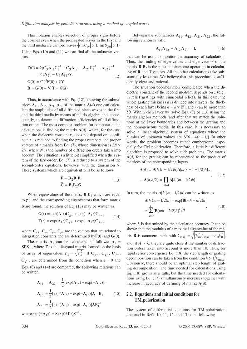
Figure 4 shows the dependences of grating transmission
from grating spacing for both polarizations. These gratings
are consisting of periodically spaced metallic bands on a
dielectric substrate (grating polarizers). The calculations
were carried out for l = 085. µm, the metal was silver
( . )e 2 35 12= - - i , the mark-to-space ratio was 0.5, the thic-
kness of metalic film was 0.1 µm. Eleven diffraction orders
were taken into account in calculations of TE-polarized
waves, and for TM-polarized waves, the calculations were
made for 11 diffraction orders using Eqs. (19) and (19a),
and for 25 diffraction orders using Eq. (19a).
The dependences in Fig. 4 have essentially different char-
acters of grating transmission for various polarizations. When
L l ratio is small, the TE wave is completely reflected from
the grating, and transmission of TM-polarized waves is close
to 0.9. The calculations have indicated that the results ob-
tained using Eqs. (19) and Eq. (19a) taking into account 11
diffraction orders differ greatly, whereas there is less differ-
ence between the results obtained using Eq. (19a) taking into
account 11 (solid curve) and 25 (dots) diffraction orders.
Using Eqs. (19) and taking into acount 11 orders of
difraction, the dependence of grating transmission from
L l in the range of 0.05 to 2/3 has smooth character with-
out valleys near L l = 0 4. and passes essentially lower
than the curves obtained using Eqs. (19a). The curves re-
ceived using Eqs. (19a) and taking into account 11 and 25
orders of diffraction are a little bit different. When take into
account only 11 orders, the curve is smooth but it has one
deep valley near L l = 0 4. , and when take 25 orders, there
are many valleys but they are rather shallow. It means, the
system of Eqs. (19a) has to be used to analyze such a grat-
ing for the case of TM polarization. This conclusion is co-
incident with the results of Refs. 16 and 17.
Opto-Electron. Rev., 13, no. 4, 2005 V.M. Fitio 337
Regular Issue Papers
Fig. 2. Schematic representation of periodic structures, (a) a diffraction grating and (b) a two-dimensional photonic crystal.
Fig. 3. Dependence of reflectivity for a grating with coupled mode resonance. S is TE polarization, P is TM polarization. Fig. 3(a) is
dependence of reflectivity from incidence angle of plane wave onto a grating. Fig. 3(b) is dependence of reflectivity from wavelength.
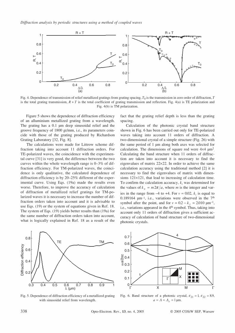
Figure 5 shows the dependence of diffraction efficiency
of an alluminium metallized grating from a wavelength.
The grating has a 0.1 µm deep sinusoidal relief and the
groove frequency of 1800 gr/mm, i.e., its parameters coin-
cide with those of the grating produced by Richardson
Grating Laboratory [32, Fig. 8].
The calculations were made for Littrow scheme dif-
fraction taking into account 11 diffraction orders. For
TE-polarized waves, the coincidence with the experimen-
tal curve [31] is very good, the difference between the two
curves within the whole wavelength range is 0–3% of dif-
fraction efficiency. For TM-polarized waves, the coinci-
dence is only qualitative, the calculated dependence of
diffraction efficiency is by 20–25% different of the exper-
imental curve. Using Eqs. (19a) made the results even
worse. Therefore, to improve the accuracy of calculation
of diffraction of metallized relief gratings for TM-po-
larized waves it is necessary to increase the number of dif-
fraction orders taken into account and it is advisable to
use Eqs. (19) or the system of equations given in Ref. 18.
The system of Eqs. (19) yields better results than (19a) for
the same number of diffraction orders taken into account,
what is logically explained in Ref. 18 as a result of the
fact that the grating relief depth is less than the grating
spacing.
Calculation of the photonic crystal band structure
shown in Fig. 6 has been carried out only for TE-polarized
waves taking into account 11 orders of diffraction. A
two-dimensional crystal of a simple structure (Fig. 26) with
the same period of 1 µm along both axes was selected for
calculation. The dimensions of square rod were 4´4 µm2.
Calculating the band structure when 11 orders of diffrac-
tion are taken into account it is necessary to find the
eigenvalues of matrix 22´22. In order to achieve the same
calculation accuracy using the traditional method [2] it is
necessary to find the eigenvalues of matrix with dimen-
sions 121´121, that lead to increasing of calculation time.
To confirm the calculation accuracy, kz was determined for
the values of k m ax = 2p , where m is the integer and var-
ies in the range from –4 to +4. For v = 002. , kz is equal to
0.189164 µm–1, i.e., variations were observed in the 7th
symbol after the point, and for v k z= - =02 2010. . µm–1,
i.e., variations appeared in the 4th symbol. Thus, taking into
account only 11 orders of diffraction gives a sufficient ac-
curacy of calculation of band structure of two-dimensional
photonic crystals.
Diffraction analysis by periodic structures using a method of coupled waves
338 Opto-Electron. Rev., 13, no. 4, 2005 © 2005 COSiW SEP, Warsaw
Fig. 4. Dependence of transmission of relief metallized gratings from grating spacing, T0 is the transmission in zero order of diffraction, T
is the total grating transmission, R T+ is the total coefficient of grating transmission and reflection. Fig. 4(a) is TE polarization and
Fig. 4(b) is TM polarization.
Fig. 5. Dependence of diffraction efficiency of a metallized grating
with sinusoidal relief from wavelength.
Fig. 6. Band structure of a photonic crystal, e21 1= , e22 89= . ,
a x= = =L L 1µm.

Regular Issue Papers
5. Conclusions
This paper offers a description of the method for analysing
light diffraction on periodic structures. The analysis is
based on solving a linear system of differential equations
taking into account exact boundary conditions. The system
of equations is obtained on the basis of the Maxwell equa-
tion. The structure of equations for describing TM polar-
ized wave diffraction is more complex than the system of
equations for TE polarized waves. Respectively, for ana-
lysing of TM polarized wave diffraction of the higher num-
ber of diffraction orders have to be taken into account. This
is especially important for metallic diffraction grating. The
results of the diffraction analysis of TE and TM polarized
waves for various types of periodic structures such as grat-
ing polarizers, gratings with coupled wave resonance and
sinusoidal relief metallized gratings are given. The band
structure for a two-dimensional photonic crystal of a sim-
ple form has been constructed.
References
1. L. Solymar and D.J. Cooke, Volume Holography and Vol-
ume Gratings, Academic Press, London, 1981.
2. J.D. Joannopoulis, R.D. Meade, and J.N. Winn, Photonic
Crystals: Molding the Flow of Light, Princeton University
Press, 1995.
3. H. Kogelnik, “Coupled wave theory for thick hologram
gratings”, Bell Syst. Tech. J. 48, 2209–2047 (1969).
4. K. Knop, “Rigorous diffraction theory for transmission
phase gratings with deep rectangular grooves”, J. Opt. Soc.
Am. 68, 1206–1210 (1978).
5. T.K. Gaylord and M.G. Moharam, “Analysis and applica-
tions of optical diffraction by grating”, Proc. IEEE 73,
894–937 (1985).
6. M.G. Moharam and T.K. Gaylord, “Chain-matrix analysis
of arbitrary-thickness dielectric reflection gratings”, J. Opt.
Soc. Am. 72, 187–190 (1982).
7. M.G. Moharam, D.A. Pommet, E.B. Grann, and T.K Gaylord,
“Stable implementation of the rigorous coupled-wave analysis
for surface-relieve dielectric gratins: enhanced transmittance
matrix approach”, J. Opt. Soc. Am. A12, 1077–1086 (1995).
8. M.G. Moharam and T.K Gaylord, “Rigorous coupled-wave
analysis of metallic surface-relief gratings”, J. Opt. Soc.
Am. A3, 1780–1787 (1986).
9. L. Li and C.W. Haggans, “Convergence of the cou-
pled-wave method for metallic lamellar diffraction grat-
ings”, J. Opt. Soc. Am. A10, 1184–1189 (1993).
10. M.G Moharam, E.B. Grann, D.A. Pommet, and T.K Gay-
lord, “Formulation for stable and efficient implementation
of the rigorous coupled-wave analysis of binary gratins”, J.
Opt. Soc. Am. A13, 1068–1077 (1996).
11. L. Li, “Use of Fourier series in the analysis of discontinuous
periodic structures”, J. Opt. Soc. Am. A12, 1870–1876 (1995).
12. V.M. Fitio and Y.V. Bobitski, “Diffraction of TE and TM po-
larization optical waves by non-absorptive media with period-
ical variation of the dielectric constant. I. Systems of differen-
tial equations”, Ukrainian J. Phys. 48, 914–920 (2003).
13. V.M. Fitio and Ya. V. Bobitski, “Diffraction of TE and TM
polarization optical waves by non-absorptive media with
periodical variation of the dielectric constant. II. Analysis of
diffraction of optical waves by non-absorbtive volume grat-
ings”, Ukrainian J. Phys. 48, 1046–1054 (2003).
14. L. Li, “Formulation and comparison of two recursive matrix
algorithms for modelling layered diffraction gratings”, J.
Opt. Soc. Am. A13, 1024–1035 (1996).
15. J. Turunen, “Form-birevringence limits of Fourier-expansion
methods in grating theory”, J. Opt. Soc. Am. A13, 1013–1018
(1996).
16. Ph. Lalanne and G.M. Morris, “Highly improved conver-
gence of the coupled-wave method for TM polarization”, J.
Opt. Soc. Am. A13, 779–784 (1996).
17. G. Granet and B. Guizal, “Efficient implementation of the
coupled-wave method for metalic lammeral gratings in TM
polarization”, J. Opt. Soc. Am. A13, 1019–1023 (1996).
18. E. Popov and M. NaviÀre, “Grating theory: new equation in
Fourier space leading to fast converging results for TM
polarisation”, J. Opt. Soc. Am. A17, 1773–1784 (2000).
19. J. Candezon, D. Maystre, and G. Raoult, “A new theoretical
method for diffraction gratings and its numerical applica-
tion”, J. Opt. (Paris) 11, 235–241 (1980).
20. T. Vallius, “Comparing the Fourier modal method with the
C method: analysis of conducting multilevel gratings in
TM-polarization”, J. Opt. Soc. Am. A19, 1555–1562 (2002).
21. B. Schnabel, E.B. Kley, and F. Wyrowski, “Study on polar-
ising visible light by subwavelength-period metal-stripe
gratings”, Opt. Eng. 38, 220–226 (1999).
22. Y. Nie, Zh. Wang, K. Fu, C. Zhou, and Q. Zhang, “Polar-
izing beamsplitter based on the effects of birefringent and
resonance anomaly”, Opt. Eng. 41, 674–679 (2002).
23. D. Shin, S. Tibuleas, T. Maldonado, and R. Magnusson,
“Thin-film optical filters with diffractive elements and
waveguides”, Opt. Eng. 37, 2634–2646 (1998).
24. Y. Nie, L. Wang, Z. Wang, and C. Lai, “Beam selector de-
pendent on incident angle by guided-mode resonant subwa-
velength grating”, Opt. Eng. 41, 2966–2969 (2002).
25. A. Mizutani, H. Kikuta, K. Ivata, and H. Toyota, “Guided-
mode resonant grating filter with an antireflection structured
surface”, J. Opt. Soc. Am. A19, 1346–1351 (2002).
26. A.L. Fehrembach, D. Maystre, and A. Sentenas, “Pheno-
menological theory of filtering by resonant dielectric grat-
ings”, J. Opt. Soc. Am. A19, 1136–1144 (2002).
27. L. Li and J. Chandenzon, “Improvement of the coordinate
transformation method for surface-relief gratings with sharp
edges”, J. Opt. Soc. Am. A13, 2247–2255 (1996).
28. H.S. Sozur, J.W. Haus, and R. Inguva, “Photonics bands:
Convergence problems with the plane-wave method”, Phys.
Rev. B45, 13962–13972 (1991).
29. R.D. Meade, A.M. Rappe, K.D. Brommer, J.D. Joanno-
poulos, and O.L. Alerhand, “Accurate theoretical analysis
of photonics band-gap materials”, Phys. Rev. B48,
8434–8437 (1993).
30. L.D. Landau and Y.M. Lifshic, Electrodynamics of Contin-
uous Media, Nauka, Moscov, 1982. (in Russian)
31. L.S. Pontryagin, Ordinary Differential Equations, Nauka,
Moscov, 1974. (in Russian)
32. Richardson Grating Laboratory, Diffraction Grating, Cata-
logue, 2001.
Opto-Electron. Rev., 13, no. 4, 2005 V.M. Fitio 339

340 Opto-Electron. Rev., 13, no. 4, 2005 © 2005 COSiW SEP, Warsaw