
Differential Pr and Flow Relationship
7
____________________________________________________________________________ Technical note 12, Differential pressure mass flow meter, rev. b, www.arian.cl 4 1.0 Basic theory. This overview intention is only to refresh the knowledge you already have from your technical studies. Also can be a introduction to the problem, but reader must have some knowledge on fluid dynamics. 1.1 Origin of differential pressure flow measurements. Bernoulli equation represents energy conservation for a fluid element: P h g Const + ⋅ + ⋅ ⋅ = 2 2 1 υ ρ ρ (1) ρ Fluid Density υ Linear velocity of the fluid element P Pressure The first term h g ⋅ ⋅ ρ is the potential energy coming from height on the gravitational field. For our development we will suppose constant height of our fluid, so this term is discarded and the equation is: P Const + ⋅ = 2 2 1 υ ρ (2) The term 2 2 1 υ ρ ⋅ is kinetic energy, here the density replaces mass. Pressure P can be understand as a potential energy. Work is stored in compressing the fluid the same way as a compressed string stores energy. We apply this equation to a circular cross section pipe that is reduced in diameter as it goes down stream in horizontal direction
-
Upload
my-name-is-neeraj -
Category
Documents
-
view
4 -
download
1
description
Differential Pr and Flow RelationshipDifferential Pr and Flow RelationshipDifferential Pr and Flow Relationship
Transcript of Differential Pr and Flow Relationship
____________________________________________________________________________ Technical note 12, Differential pressure mass flow meter, rev. b, www.arian.cl 4
1.0 Basic theory.
This overview intention is only to refresh the knowledge you already have from your technical studies. Also can be a introduction to the problem, but reader must have some knowledge on fluid dynamics.
1.1 Origin of differential pressure flow measurements.
Bernoulli equation represents energy conservation for a fluid element:
PhgConst +⋅+⋅⋅= 2
2
1 υρρ (1)
ρ Fluid Density υ Linear velocity of the fluid element
P Pressure The first term hg ⋅⋅ρ is the potential energy coming from height on the gravitational field. For our development we will suppose constant height of our fluid, so this term is discarded and the equation is:
PConst +⋅= 2
2
1 υρ (2)
The term 2
2
1 υρ ⋅ is kinetic energy, here the density replaces mass.
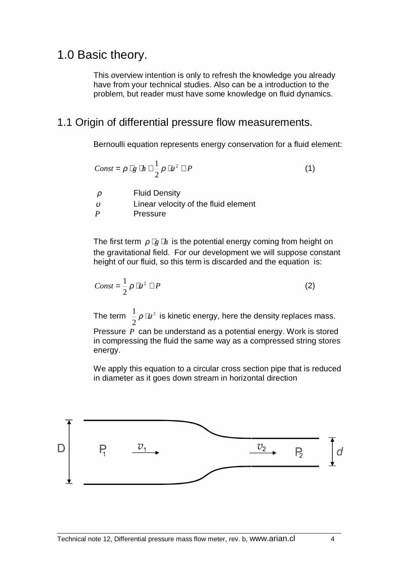
Pressure P can be understand as a potential energy. Work is stored in compressing the fluid the same way as a compressed string stores energy. We apply this equation to a circular cross section pipe that is reduced in diameter as it goes down stream in horizontal direction

____________________________________________________________________________ Technical note 12, Differential pressure mass flow meter, rev. b, www.arian.cl 5
22221
211 2
1
2
1PP +⋅=+⋅ υρυρ (3)
1ρ , 1υ , 1P Up stream density, velocity and pressure 2ρ , 2υ , 2P Down stream density, velocity and pressure
By other side mass is conserved (not created nor destroyed) as it flows along the pipe, this is represented by the formulas
111222 AAQM ⋅⋅=⋅⋅= υρυρ (4)
MQ Mass flow rate along the pipe, units are e.g. Kg/sec
2A , 1A Up and down stream cross sectional area of the pipe Squaring both sides of (4), and solving for 2
2υ we have
2
22
1121
22 )(
A
A
⋅⋅⋅=
ρρυυ (5)
From (3), we have
211
22221 )(2 υρυρ ⋅−⋅=−⋅ PP
Substituting 2
2υ from (5) into this equation
222
222
21
211
222
121
2
22
1122
2121 )(
))()(())(()(2
A
AA
A
APP
⋅⋅⋅−⋅⋅⋅=−
⋅⋅⋅=−⋅
ρρρρρυρ
ρρρυ
From this equations, 1υ can be written as
))()((
)()(2
222
21
211
22
222
211 AA
APP
⋅⋅−⋅⋅⋅⋅−⋅=
ρρρρρυ
This value of is substituted on (4)
____________________________________________________________________________ Technical note 12, Differential pressure mass flow meter, rev. b, www.arian.cl 6
))()((
)()()(2
222
21
211
22
222
211
21111 AA
AAPPAQM ⋅⋅−⋅⋅
⋅⋅⋅⋅−⋅=⋅⋅=ρρρρ
ρρυρ (4a)
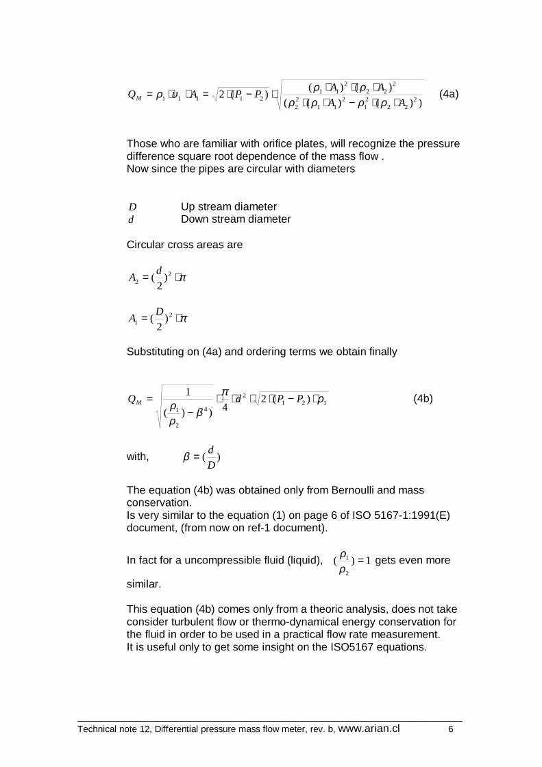
Those who are familiar with orifice plates, will recognize the pressure difference square root dependence of the mass flow . Now since the pipes are circular with diameters D Up stream diameter d Down stream diameter Circular cross areas are
π⋅= 22 )
2(d
A
π⋅= 21 )
2(D
A
Substituting on (4a) and ordering terms we obtain finally
1212
4
2
1
)(24))(
1 ρπ
βρρ ⋅−⋅⋅⋅⋅
−= PPdQM (4b)
with, )(D
d=β
The equation (4b) was obtained only from Bernoulli and mass conservation. Is very similar to the equation (1) on page 6 of ISO 5167-1:1991(E) document, (from now on ref-1 document).
In fact for a uncompressible fluid (liquid), 1)(2
1 =ρρ
gets even more
similar. This equation (4b) comes only from a theoric analysis, does not take consider turbulent flow or thermo-dynamical energy conservation for the fluid in order to be used in a practical flow rate measurement. It is useful only to get some insight on the ISO5167 equations.
____________________________________________________________________________ Technical note 12, Differential pressure mass flow meter, rev. b, www.arian.cl 7
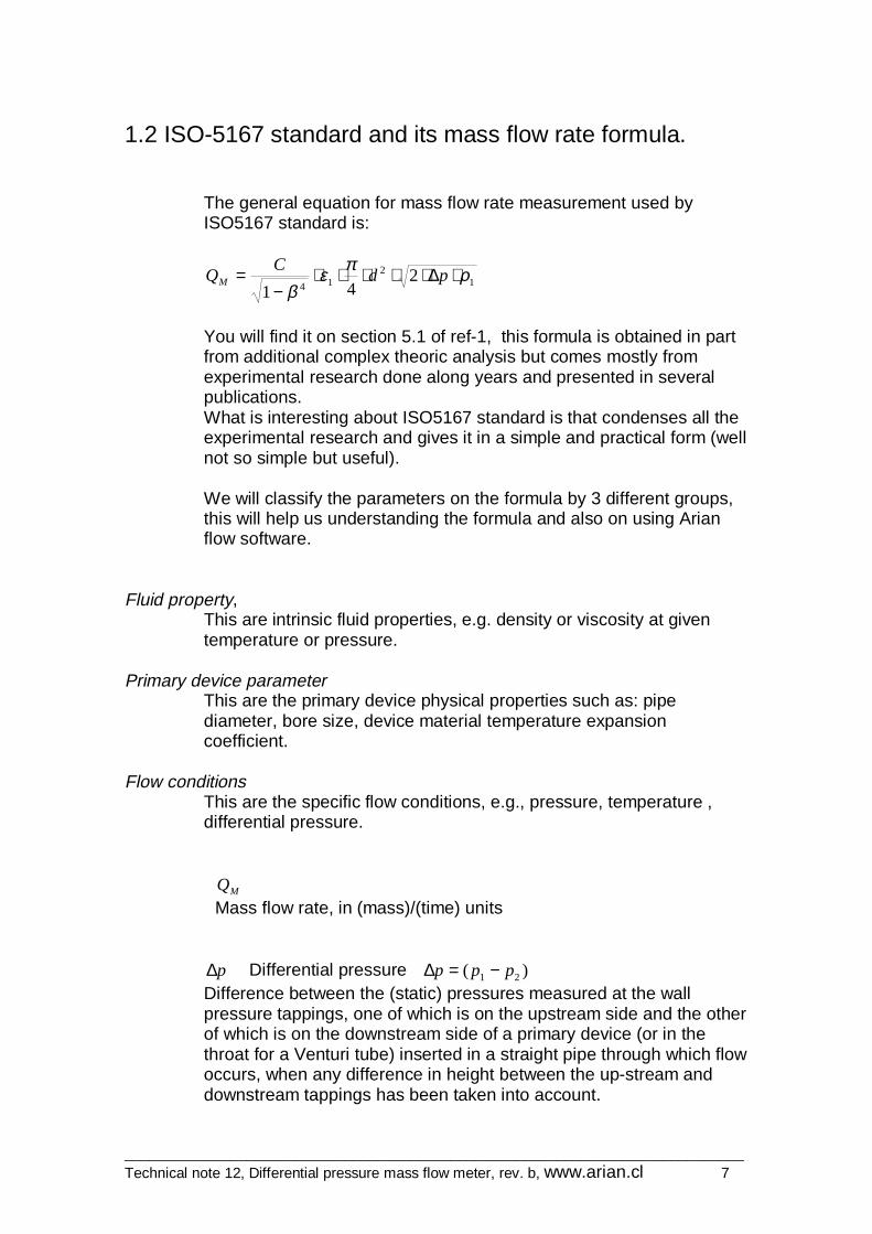
1.2 ISO-5167 standard and its mass flow rate formula.
The general equation for mass flow rate measurement used by ISO5167 standard is:
12
142
41ρπε
β⋅∆⋅⋅⋅⋅⋅
−= pd
CQM
You will find it on section 5.1 of ref-1, this formula is obtained in part from additional complex theoric analysis but comes mostly from experimental research done along years and presented in several publications. What is interesting about ISO5167 standard is that condenses all the experimental research and gives it in a simple and practical form (well not so simple but useful). We will classify the parameters on the formula by 3 different groups, this will help us understanding the formula and also on using Arian flow software.
Fluid property, This are intrinsic fluid properties, e.g. density or viscosity at given temperature or pressure.
Primary device parameter This are the primary device physical properties such as: pipe diameter, bore size, device material temperature expansion coefficient.
Flow conditions This are the specific flow conditions, e.g., pressure, temperature , differential pressure.
MQ Mass flow rate, in (mass)/(time) units
p∆ Differential pressure )( 21 ppp −=∆ Difference between the (static) pressures measured at the wall pressure tappings, one of which is on the upstream side and the other of which is on the downstream side of a primary device (or in the throat for a Venturi tube) inserted in a straight pipe through which flow occurs, when any difference in height between the up-stream and downstream tappings has been taken into account.
____________________________________________________________________________ Technical note 12, Differential pressure mass flow meter, rev. b, www.arian.cl 8
1ρ Up stream fluid density.
d Bore diameter
D Pipe diameter
β Diameter ratio
This is a geometric parameter of the device, that is calculated using
D
d=β
1ε Expansion factor. (Up stream evaluated)
Coefficient used to take into account the compressibility of the fluid. The numerical values of 1ε for orifice plates given in ISO5167 are based on data determined experimentally. For nozzles and Venturi tubes they are based on the thermodynamic general energy equation. For liquids (uncompressible fluids), is always 11 =ε For steam and gases (compressible fluids) 11 <ε . Is calculated with different formulas depending on the device geometry. For example for a orifice plate, ISO5167-1:1991(E) section 8.3.2.2 gives on the following formula:
1
41 )35.041.0(1
pk
p
⋅∆⋅⋅+−= βε
Where k is the isentropic exponent, a “Fluid property” that depends on fluid pressure and temperature. Is related with adiabatic expansion of the fluid in the bore zone. C Discharge coefficient Is a coefficient, defined for an incompressible fluid flow, which relates the actual flow-rate to the theoretical flow-rate through a device. Is related with turbulent flow and the restriction the devices makes to the flow. Again the formula for evaluating it, comes from empirical data, for example for a orifice plate, the formula used by ISO5167-1:1991 section 8.3.2.1 on page 22.
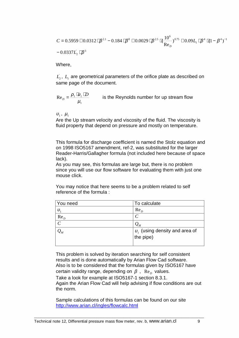
____________________________________________________________________________ Technical note 12, Differential pressure mass flow meter, rev. b, www.arian.cl 9
3'2
1441
75.06
5.281.2
0337.0
)1(09.0)Re
10(0029.0184.00312.05959.0
β
βββββ
⋅−
−⋅⋅+⋅⋅+⋅−⋅+= −
L
LCD
Where,
'2L , 1L are geometrical parameters of the orifice plate as described on
same page of the document.
1
11Reµυρ D
D
⋅⋅= is the Reynolds number for up stream flow
1υ , 1µ Are the Up stream velocity and viscosity of the fluid. The viscosity is fluid property that depend on pressure and mostly on temperature. This formula for discharge coefficient is named the Stolz equation and on 1998 ISO5167 amendment, ref-2, was substituted for the larger Reader-Harris/Gallagher formula (not included here because of space lack). As you may see, this formulas are large but, there is no problem since you will use our flow software for evaluating them with just one mouse click. You may notice that here seems to be a problem related to self reference of the formula : You need To calculate
1υ DRe
DRe C
C MQ
MQ 1υ (using density and area of the pipe)
This problem is solved by iteration searching for self consistent results and is done automatically by Arian Flow Cad software. Also is to be considered that the formulas given by ISO5167 have certain validity range, depending on β , DRe values. Take a look for example at ISO5167-1 section 8.3.1. Again the Arian Flow Cad will help advising if flow conditions are out the norm. Sample calculations of this formulas can be found on our site http://www.arian.cl/ingles/flowcalc.html
____________________________________________________________________________ Technical note 12, Differential pressure mass flow meter, rev. b, www.arian.cl 10
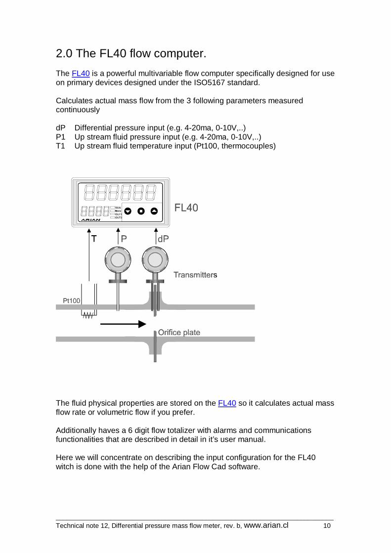
2.0 The FL40 flow computer. The FL40 is a powerful multivariable flow computer specifically designed for use on primary devices designed under the ISO5167 standard. Calculates actual mass flow from the 3 following parameters measured continuously dP Differential pressure input (e.g. 4-20ma, 0-10V,..) P1 Up stream fluid pressure input (e.g. 4-20ma, 0-10V,..) T1 Up stream fluid temperature input (Pt100, thermocouples)
The fluid physical properties are stored on the FL40 so it calculates actual mass flow rate or volumetric flow if you prefer. Additionally haves a 6 digit flow totalizer with alarms and communications functionalities that are described in detail in it’s user manual. Here we will concentrate on describing the input configuration for the FL40 witch is done with the help of the Arian Flow Cad software.


![DP-Finder: Finding Differential Privacy Violations by ... · yes no yes. How precise is our estimate? Precision of Pr[ 𝑥∈Φ] and Pr[ 𝑥′∈Φ] Sampling ... • How efficient](https://static.fdocuments.in/doc/165x107/5ccaa36188c993b16c8be7e5/dp-finder-finding-differential-privacy-violations-by-yes-no-yes-how-precise.jpg)


