DIFFERENTIAL POLARIZATION DELAY LINE controller D0215 Supervisor : Mony Orbach Performed by: Maria...
27
DIFFERENTIAL POLARIZATION DELAY LINE controller D0215 Supervisor : Supervisor : Mony Orbach Mony Orbach Performed by: Performed by: Maria Terushkin Maria Terushkin Guy Ovadia Guy Ovadia Technion – Israel Institute of Technology Department of Electrical Engineering High Speed Digital Systems Lab
-
date post
20-Dec-2015 -
Category
Documents
-
view
217 -
download
0
Transcript of DIFFERENTIAL POLARIZATION DELAY LINE controller D0215 Supervisor : Mony Orbach Performed by: Maria...
DIFFERENTIAL POLARIZATION DELAY
LINE controller
D0215
Supervisor Supervisor Mony OrbachMony Orbach
Performed byPerformed byMaria TerushkinMaria Terushkin
Guy OvadiaGuy Ovadia
Technion ndash Israel Institute of TechnologyDepartment of Electrical EngineeringHigh Speed Digital Systems Lab
Project definitionProject definition
Build a controller for the Differential Delay Line module in the facultyrsquos EO lab
Precisely determine and control the position of the mirror inside the module
Closed loop positional control using the built in optical shaft encoder for feedback
Create a PC interface through a USB connection
Project FeaturesProject Features
Closed-loop motor control (PID algorithm)Closed-loop motor control (PID algorithm) Interface Functions Interface Functions
Go to specified positionGo to specified position Set zero positionSet zero position Read-back of current positionRead-back of current position
Apply motor break while holding positionApply motor break while holding position Slow down gradually near travel limitsSlow down gradually near travel limits Built In Tests (discussed later in the Built In Tests (discussed later in the
presentation)presentation)
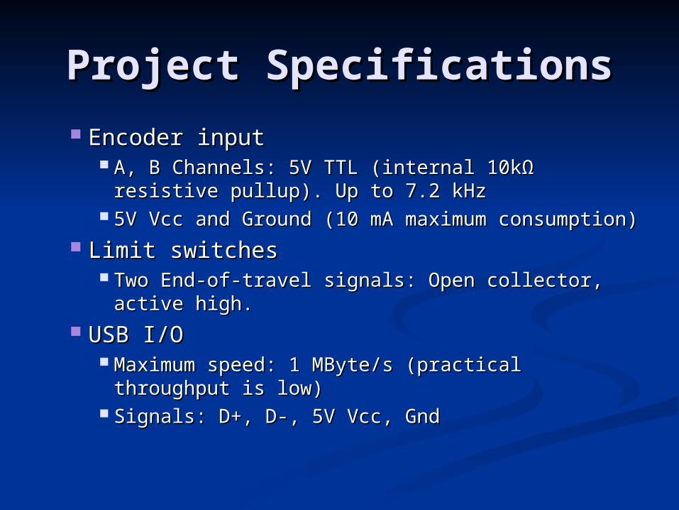
Project SpecificationsProject Specifications
Encoder inputEncoder input A B Channels 5V TTL (internal 10kA B Channels 5V TTL (internal 10kΩΩ resistive resistive
pullup) Up to 72 kHzpullup) Up to 72 kHz 5V Vcc and Ground (10 mA maximum 5V Vcc and Ground (10 mA maximum
consumption)consumption) Limit switchesLimit switches
Two End-of-travel signals Open collector active Two End-of-travel signals Open collector active highhigh
USB IOUSB IO Maximum speed 1 MBytes (practical throughput Maximum speed 1 MBytes (practical throughput
is low)is low) Signals D+ D- 5V Vcc GndSignals D+ D- 5V Vcc Gnd
Mechanical aspectsMechanical aspects
Method of construction Wireup cardMethod of construction Wireup card Connections to the MMC card direct Connections to the MMC card direct
solderingsoldering Enclosure pre-made boxEnclosure pre-made box External connectorsExternal connectors
Power connectorPower connector DDL connectorDDL connector
No heatsinks are requiredNo heatsinks are required
Project SpecificationsProject Specifications
PerformancePerformance (preliminary requirements)(preliminary requirements)
Steady State Positional Error lt 05 microm (single Steady State Positional Error lt 05 microm (single encoder step)encoder step)
Commulative positional error 0 micromCommulative positional error 0 microm Overshoot 25 [] (non critical but should be Overshoot 25 [] (non critical but should be
lowered near travel limits)lowered near travel limits) Small Step settling time (to 05 microm) will be Small Step settling time (to 05 microm) will be
setted on the real modelsetted on the real model Full travel settling time (to 05 microm) will be Full travel settling time (to 05 microm) will be
setted on the real modelsetted on the real model Limit velocity to +- 1 [mms]Limit velocity to +- 1 [mms]
Block diagramBlock diagram
DDL
controller
PC + simple UI
USBCommunicationUnit
Laboratory measurement equipment
Fiber optics
DDL ndash controller diagramDDL ndash controller diagram
Limit Switches
DC motor
Encoder
H-bridge
Power supply
12MHz clk
FPGA
DDL
The chosen H-bridge The chosen H-bridge HIP4020 HIP4020
Two Independently controlled power Half-Bridges 3-12V operation 05A Maximum load CMOSTTL Compatible Input Logic Over-Temperature Shutdown Protection Over current Limit Protection Over current Fault Flag Output Direction Braking and PWM Control Manufacturer Intersil Low cost available from Farnell
MMC PlatformMMC Platform
The project is based on a platform The project is based on a platform previously designed in the HS-DSLpreviously designed in the HS-DSL
The platform we will use is the The platform we will use is the Momentum Measurement Card created Momentum Measurement Card created by Hadas Preminger amp Uri Nivby Hadas Preminger amp Uri Niv
Project SpecificationsProject Specifications IO SignalsIO Signals
Input powerInput power 9V 1A wall adapter9V 1A wall adapter Typical consumption (motor running) TBDTypical consumption (motor running) TBD
estimated at 250mA (15W)estimated at 250mA (15W) Typical consumption (motor idle) TBD Typical consumption (motor idle) TBD
estimated at 50mA ( 025 W)estimated at 50mA ( 025 W) Motor outputMotor output
Fixed frequency PWM signal at 20 kHzFixed frequency PWM signal at 20 kHz Reversible polarityReversible polarity 6 V nominal adjustable by trimpot between 3-8 V for 6 V nominal adjustable by trimpot between 3-8 V for
calibration during development (unaccessible to user)calibration during development (unaccessible to user) 250mA max current (limited by motor resistance)250mA max current (limited by motor resistance)
Cyclone FPGACyclone FPGA
Alterarsquos low cost simple FPGA
2910 Logic Elements ~60000 kBit RAM clock PLL gt100 IO pins JTAG support
Suitable for implementing glue logic MCU function signal processing and more
Built In TestsBuilt In Tests
Test distance between limit Test distance between limit switchesswitchesresult must be in specific rangeresult must be in specific range
Move forward then backward by the Move forward then backward by the same amount Verify that the same amount Verify that the position is the sameposition is the same
Move to a specific location Perform Move to a specific location Perform readback of location Verify that it is readback of location Verify that it is the same positionthe same position
Acceptance TestsAcceptance Tests
All Built In Tests are also acceptance testsAll Built In Tests are also acceptance tests Arriving a specified position by a preset time Arriving a specified position by a preset time
Separate tests for both directionsSeparate tests for both directions Test for small step (10um) medium step (1000um) Test for small step (10um) medium step (1000um)
and full travel rangeand full travel range Holding position position change while idle is Holding position position change while idle is
up to 1 encoder countup to 1 encoder count Travel near limit switches measured velocity Travel near limit switches measured velocity
drops near the limits Movement stops if limit drops near the limits Movement stops if limit switch is hitswitch is hit
The modelThe model
The modelThe model Two axis motion control mechanism (we Two axis motion control mechanism (we
use only one stage)use only one stage) Includes motor encoder and limit Includes motor encoder and limit
switchesswitches Model can work with the same interface Model can work with the same interface
with minimal adaptationswith minimal adaptations Some parameters will needed to be Some parameters will needed to be
adjusted separately to the modeladjusted separately to the model PID parameters Ki Kd KpPID parameters Ki Kd Kp Velocity and Acceleration planning adjustmentVelocity and Acceleration planning adjustment Supply voltageSupply voltage
Controller typeController type
PID algorithms adjust the gain to the plant based on several characteristics of the feedback not just the current value The error term is derived by subtracting the feedback
(motor position) from the set point (set position) This is the error in terms of a number of encoder counts
1048708Simple proportional coefficient Kp is multiplied by the error term
Provides linear response to the error term Integral coefficient Ki is multiplied by the error term and
added to the sum of all previous integral terms 1048708Provides response to accumulated error
Derivative coefficient Kd is multiplied by the difference between the previous error and the current error
1048708Responds to change in error from one PID cycle to the next
PID controller - overviewPID controller - overview
Effects of changes in parametersEffects of changes in parameters Parameter Rise Time Overshoot Settling Time Parameter Rise Time Overshoot Settling Time
SSError SSError P P Decrease Increase Small Change Decrease Increase Small Change
Decrease Decrease I I Decrease Increase Increase Decrease Increase Increase
Eliminate Eliminate D D Small Change Decrease Decrease Small Change Decrease Decrease
Small Change Small ChangeVset
Vsensor
P
I
D
sensor
plant amp
Vout +
-+
Pitfalls of PIDPitfalls of PID
Integral windupIntegral windup The problem arises when the actuator The problem arises when the actuator
saturatessaturates There is no longer a linear relation between There is no longer a linear relation between
the controller output to the plantrsquos reactionthe controller output to the plantrsquos reaction When this happens the integrator sums the When this happens the integrator sums the
large error and reaches a very high valuelarge error and reaches a very high value When the error is finally reduced it would When the error is finally reduced it would
take a long time for the integrator to take a long time for the integrator to ldquounwindrdquo and fall back to a normal valueldquounwindrdquo and fall back to a normal value
This is called ldquoIntegral Winduprdquo
Commonly used schemes to reduce the effects of integrator windup
Clamp the integrator output This scheme simply involves clamping the integrator output at a specified maximum level
ContCont Stop integration on saturation This
scheme involves switching off the input to the integrator when the actuator goes into saturation
ContCont Saturation feedback This scheme
involves an extra feedback loop reducing the input to integrator in proportion to the saturation error signal
Tuning the PID controllerTuning the PID controllerThe Ziegler-Nichols method The Ziegler-Nichols method The The closed loop methodclosed loop method prescribes the prescribes the
following procedure following procedure Step 1Step 1 Disable any D and I action of the controller Disable any D and I action of the controller
(--gt pure P-controller) (--gt pure P-controller) Step 2Step 2 Make a setpoint step test and observe the Make a setpoint step test and observe the
response response Step 3Step 3 Repeat the SP test with increased decreased Repeat the SP test with increased decreased
controller gain until a stable oscillation is achieved controller gain until a stable oscillation is achieved This gain is called the ultimate gain Ku This gain is called the ultimate gain Ku
Step 4Step 4 Read the oscillation period Pu Read the oscillation period Pu Step 5Step 5 Calculate the parameters according to the Calculate the parameters according to the
following formulas following formulas PIPI Proportional gain = 045 Ku integral time =Pu 12 Proportional gain = 045 Ku integral time =Pu 12 PIDPID Proportional gain = 06 Ku integral time =Pu 2 Proportional gain = 06 Ku integral time =Pu 2
derivative time = Tu 8derivative time = Tu 8
An alternativehellipAn alternativehellip
As an alternative to the table above As an alternative to the table above another set of tuning values have been another set of tuning values have been determined by Tyreus and Luyblen for determined by Tyreus and Luyblen for PI and PID often called the TLC tuning PI and PID often called the TLC tuning rules These values tend to reduce rules These values tend to reduce oscillatory effects and improves oscillatory effects and improves robustness robustness
Since in our system it is important to Since in our system it is important to avoid oscillatory effects wersquoll use this avoid oscillatory effects wersquoll use this methodmethod
Logic designLogic design
PID
Trajectory
Planning
Xf
M
err
Current via point
To
Tf
Tf1 Xf1
Tf2 Xf2
hellip hellip
Tff Xff
Yes
Yes
End of trajectory
Arrived via point ndash err=0
MilestonesMilestones 15012006 - Electrical schematics done15012006 - Electrical schematics done 25012006 - 25012006 -
Test system built and tested to satisfy our needs Test system built and tested to satisfy our needs Mechanical design completeMechanical design complete
03022006 - Logical design of the system finished03022006 - Logical design of the system finished 05022006 ndash system assembled and programmed05022006 ndash system assembled and programmed 08022006 ndash preliminary testing on the model done08022006 ndash preliminary testing on the model done 20022006 ndash debugging finished20022006 ndash debugging finished 23022006 - PC software written23022006 - PC software written 01032006 - Controller integrated with the real 01032006 - Controller integrated with the real
systemsystem 05032006 ndash Design finalized (including enclosure 05032006 ndash Design finalized (including enclosure
wiring etc) wiring etc) 06032006 - Integration with the setup at the EO lab06032006 - Integration with the setup at the EO lab
The enDThe enD

Project definitionProject definition
Build a controller for the Differential Delay Line module in the facultyrsquos EO lab
Precisely determine and control the position of the mirror inside the module
Closed loop positional control using the built in optical shaft encoder for feedback
Create a PC interface through a USB connection
Project FeaturesProject Features
Closed-loop motor control (PID algorithm)Closed-loop motor control (PID algorithm) Interface Functions Interface Functions
Go to specified positionGo to specified position Set zero positionSet zero position Read-back of current positionRead-back of current position
Apply motor break while holding positionApply motor break while holding position Slow down gradually near travel limitsSlow down gradually near travel limits Built In Tests (discussed later in the Built In Tests (discussed later in the
presentation)presentation)
Project SpecificationsProject Specifications
Encoder inputEncoder input A B Channels 5V TTL (internal 10kA B Channels 5V TTL (internal 10kΩΩ resistive resistive
pullup) Up to 72 kHzpullup) Up to 72 kHz 5V Vcc and Ground (10 mA maximum 5V Vcc and Ground (10 mA maximum
consumption)consumption) Limit switchesLimit switches
Two End-of-travel signals Open collector active Two End-of-travel signals Open collector active highhigh
USB IOUSB IO Maximum speed 1 MBytes (practical throughput Maximum speed 1 MBytes (practical throughput
is low)is low) Signals D+ D- 5V Vcc GndSignals D+ D- 5V Vcc Gnd
Mechanical aspectsMechanical aspects
Method of construction Wireup cardMethod of construction Wireup card Connections to the MMC card direct Connections to the MMC card direct
solderingsoldering Enclosure pre-made boxEnclosure pre-made box External connectorsExternal connectors
Power connectorPower connector DDL connectorDDL connector
No heatsinks are requiredNo heatsinks are required
Project SpecificationsProject Specifications
PerformancePerformance (preliminary requirements)(preliminary requirements)
Steady State Positional Error lt 05 microm (single Steady State Positional Error lt 05 microm (single encoder step)encoder step)
Commulative positional error 0 micromCommulative positional error 0 microm Overshoot 25 [] (non critical but should be Overshoot 25 [] (non critical but should be
lowered near travel limits)lowered near travel limits) Small Step settling time (to 05 microm) will be Small Step settling time (to 05 microm) will be
setted on the real modelsetted on the real model Full travel settling time (to 05 microm) will be Full travel settling time (to 05 microm) will be
setted on the real modelsetted on the real model Limit velocity to +- 1 [mms]Limit velocity to +- 1 [mms]
Block diagramBlock diagram
DDL
controller
PC + simple UI
USBCommunicationUnit
Laboratory measurement equipment
Fiber optics
DDL ndash controller diagramDDL ndash controller diagram
Limit Switches
DC motor
Encoder
H-bridge
Power supply
12MHz clk
FPGA
DDL
The chosen H-bridge The chosen H-bridge HIP4020 HIP4020
Two Independently controlled power Half-Bridges 3-12V operation 05A Maximum load CMOSTTL Compatible Input Logic Over-Temperature Shutdown Protection Over current Limit Protection Over current Fault Flag Output Direction Braking and PWM Control Manufacturer Intersil Low cost available from Farnell
MMC PlatformMMC Platform
The project is based on a platform The project is based on a platform previously designed in the HS-DSLpreviously designed in the HS-DSL
The platform we will use is the The platform we will use is the Momentum Measurement Card created Momentum Measurement Card created by Hadas Preminger amp Uri Nivby Hadas Preminger amp Uri Niv
Project SpecificationsProject Specifications IO SignalsIO Signals
Input powerInput power 9V 1A wall adapter9V 1A wall adapter Typical consumption (motor running) TBDTypical consumption (motor running) TBD
estimated at 250mA (15W)estimated at 250mA (15W) Typical consumption (motor idle) TBD Typical consumption (motor idle) TBD
estimated at 50mA ( 025 W)estimated at 50mA ( 025 W) Motor outputMotor output
Fixed frequency PWM signal at 20 kHzFixed frequency PWM signal at 20 kHz Reversible polarityReversible polarity 6 V nominal adjustable by trimpot between 3-8 V for 6 V nominal adjustable by trimpot between 3-8 V for
calibration during development (unaccessible to user)calibration during development (unaccessible to user) 250mA max current (limited by motor resistance)250mA max current (limited by motor resistance)
Cyclone FPGACyclone FPGA
Alterarsquos low cost simple FPGA
2910 Logic Elements ~60000 kBit RAM clock PLL gt100 IO pins JTAG support
Suitable for implementing glue logic MCU function signal processing and more
Built In TestsBuilt In Tests
Test distance between limit Test distance between limit switchesswitchesresult must be in specific rangeresult must be in specific range
Move forward then backward by the Move forward then backward by the same amount Verify that the same amount Verify that the position is the sameposition is the same
Move to a specific location Perform Move to a specific location Perform readback of location Verify that it is readback of location Verify that it is the same positionthe same position
Acceptance TestsAcceptance Tests
All Built In Tests are also acceptance testsAll Built In Tests are also acceptance tests Arriving a specified position by a preset time Arriving a specified position by a preset time
Separate tests for both directionsSeparate tests for both directions Test for small step (10um) medium step (1000um) Test for small step (10um) medium step (1000um)
and full travel rangeand full travel range Holding position position change while idle is Holding position position change while idle is
up to 1 encoder countup to 1 encoder count Travel near limit switches measured velocity Travel near limit switches measured velocity
drops near the limits Movement stops if limit drops near the limits Movement stops if limit switch is hitswitch is hit
The modelThe model
The modelThe model Two axis motion control mechanism (we Two axis motion control mechanism (we
use only one stage)use only one stage) Includes motor encoder and limit Includes motor encoder and limit
switchesswitches Model can work with the same interface Model can work with the same interface
with minimal adaptationswith minimal adaptations Some parameters will needed to be Some parameters will needed to be
adjusted separately to the modeladjusted separately to the model PID parameters Ki Kd KpPID parameters Ki Kd Kp Velocity and Acceleration planning adjustmentVelocity and Acceleration planning adjustment Supply voltageSupply voltage
Controller typeController type
PID algorithms adjust the gain to the plant based on several characteristics of the feedback not just the current value The error term is derived by subtracting the feedback
(motor position) from the set point (set position) This is the error in terms of a number of encoder counts
1048708Simple proportional coefficient Kp is multiplied by the error term
Provides linear response to the error term Integral coefficient Ki is multiplied by the error term and
added to the sum of all previous integral terms 1048708Provides response to accumulated error
Derivative coefficient Kd is multiplied by the difference between the previous error and the current error
1048708Responds to change in error from one PID cycle to the next
PID controller - overviewPID controller - overview
Effects of changes in parametersEffects of changes in parameters Parameter Rise Time Overshoot Settling Time Parameter Rise Time Overshoot Settling Time
SSError SSError P P Decrease Increase Small Change Decrease Increase Small Change
Decrease Decrease I I Decrease Increase Increase Decrease Increase Increase
Eliminate Eliminate D D Small Change Decrease Decrease Small Change Decrease Decrease
Small Change Small ChangeVset
Vsensor
P
I
D
sensor
plant amp
Vout +
-+
Pitfalls of PIDPitfalls of PID
Integral windupIntegral windup The problem arises when the actuator The problem arises when the actuator
saturatessaturates There is no longer a linear relation between There is no longer a linear relation between
the controller output to the plantrsquos reactionthe controller output to the plantrsquos reaction When this happens the integrator sums the When this happens the integrator sums the
large error and reaches a very high valuelarge error and reaches a very high value When the error is finally reduced it would When the error is finally reduced it would
take a long time for the integrator to take a long time for the integrator to ldquounwindrdquo and fall back to a normal valueldquounwindrdquo and fall back to a normal value
This is called ldquoIntegral Winduprdquo
Commonly used schemes to reduce the effects of integrator windup
Clamp the integrator output This scheme simply involves clamping the integrator output at a specified maximum level
ContCont Stop integration on saturation This
scheme involves switching off the input to the integrator when the actuator goes into saturation
ContCont Saturation feedback This scheme
involves an extra feedback loop reducing the input to integrator in proportion to the saturation error signal
Tuning the PID controllerTuning the PID controllerThe Ziegler-Nichols method The Ziegler-Nichols method The The closed loop methodclosed loop method prescribes the prescribes the
following procedure following procedure Step 1Step 1 Disable any D and I action of the controller Disable any D and I action of the controller
(--gt pure P-controller) (--gt pure P-controller) Step 2Step 2 Make a setpoint step test and observe the Make a setpoint step test and observe the
response response Step 3Step 3 Repeat the SP test with increased decreased Repeat the SP test with increased decreased
controller gain until a stable oscillation is achieved controller gain until a stable oscillation is achieved This gain is called the ultimate gain Ku This gain is called the ultimate gain Ku
Step 4Step 4 Read the oscillation period Pu Read the oscillation period Pu Step 5Step 5 Calculate the parameters according to the Calculate the parameters according to the
following formulas following formulas PIPI Proportional gain = 045 Ku integral time =Pu 12 Proportional gain = 045 Ku integral time =Pu 12 PIDPID Proportional gain = 06 Ku integral time =Pu 2 Proportional gain = 06 Ku integral time =Pu 2
derivative time = Tu 8derivative time = Tu 8
An alternativehellipAn alternativehellip
As an alternative to the table above As an alternative to the table above another set of tuning values have been another set of tuning values have been determined by Tyreus and Luyblen for determined by Tyreus and Luyblen for PI and PID often called the TLC tuning PI and PID often called the TLC tuning rules These values tend to reduce rules These values tend to reduce oscillatory effects and improves oscillatory effects and improves robustness robustness
Since in our system it is important to Since in our system it is important to avoid oscillatory effects wersquoll use this avoid oscillatory effects wersquoll use this methodmethod
Logic designLogic design
PID
Trajectory
Planning
Xf
M
err
Current via point
To
Tf
Tf1 Xf1
Tf2 Xf2
hellip hellip
Tff Xff
Yes
Yes
End of trajectory
Arrived via point ndash err=0
MilestonesMilestones 15012006 - Electrical schematics done15012006 - Electrical schematics done 25012006 - 25012006 -
Test system built and tested to satisfy our needs Test system built and tested to satisfy our needs Mechanical design completeMechanical design complete
03022006 - Logical design of the system finished03022006 - Logical design of the system finished 05022006 ndash system assembled and programmed05022006 ndash system assembled and programmed 08022006 ndash preliminary testing on the model done08022006 ndash preliminary testing on the model done 20022006 ndash debugging finished20022006 ndash debugging finished 23022006 - PC software written23022006 - PC software written 01032006 - Controller integrated with the real 01032006 - Controller integrated with the real
systemsystem 05032006 ndash Design finalized (including enclosure 05032006 ndash Design finalized (including enclosure
wiring etc) wiring etc) 06032006 - Integration with the setup at the EO lab06032006 - Integration with the setup at the EO lab
The enDThe enD
Project SpecificationsProject Specifications
Encoder inputEncoder input A B Channels 5V TTL (internal 10kA B Channels 5V TTL (internal 10kΩΩ resistive resistive
pullup) Up to 72 kHzpullup) Up to 72 kHz 5V Vcc and Ground (10 mA maximum 5V Vcc and Ground (10 mA maximum
consumption)consumption) Limit switchesLimit switches
Two End-of-travel signals Open collector active Two End-of-travel signals Open collector active highhigh
USB IOUSB IO Maximum speed 1 MBytes (practical throughput Maximum speed 1 MBytes (practical throughput
is low)is low) Signals D+ D- 5V Vcc GndSignals D+ D- 5V Vcc Gnd
Mechanical aspectsMechanical aspects
Method of construction Wireup cardMethod of construction Wireup card Connections to the MMC card direct Connections to the MMC card direct
solderingsoldering Enclosure pre-made boxEnclosure pre-made box External connectorsExternal connectors
Power connectorPower connector DDL connectorDDL connector
No heatsinks are requiredNo heatsinks are required
Project SpecificationsProject Specifications
PerformancePerformance (preliminary requirements)(preliminary requirements)
Steady State Positional Error lt 05 microm (single Steady State Positional Error lt 05 microm (single encoder step)encoder step)
Commulative positional error 0 micromCommulative positional error 0 microm Overshoot 25 [] (non critical but should be Overshoot 25 [] (non critical but should be
lowered near travel limits)lowered near travel limits) Small Step settling time (to 05 microm) will be Small Step settling time (to 05 microm) will be
setted on the real modelsetted on the real model Full travel settling time (to 05 microm) will be Full travel settling time (to 05 microm) will be
setted on the real modelsetted on the real model Limit velocity to +- 1 [mms]Limit velocity to +- 1 [mms]
Block diagramBlock diagram
DDL
controller
PC + simple UI
USBCommunicationUnit
Laboratory measurement equipment
Fiber optics
DDL ndash controller diagramDDL ndash controller diagram
Limit Switches
DC motor
Encoder
H-bridge
Power supply
12MHz clk
FPGA
DDL
The chosen H-bridge The chosen H-bridge HIP4020 HIP4020
Two Independently controlled power Half-Bridges 3-12V operation 05A Maximum load CMOSTTL Compatible Input Logic Over-Temperature Shutdown Protection Over current Limit Protection Over current Fault Flag Output Direction Braking and PWM Control Manufacturer Intersil Low cost available from Farnell
MMC PlatformMMC Platform
The project is based on a platform The project is based on a platform previously designed in the HS-DSLpreviously designed in the HS-DSL
The platform we will use is the The platform we will use is the Momentum Measurement Card created Momentum Measurement Card created by Hadas Preminger amp Uri Nivby Hadas Preminger amp Uri Niv
Project SpecificationsProject Specifications IO SignalsIO Signals
Input powerInput power 9V 1A wall adapter9V 1A wall adapter Typical consumption (motor running) TBDTypical consumption (motor running) TBD
estimated at 250mA (15W)estimated at 250mA (15W) Typical consumption (motor idle) TBD Typical consumption (motor idle) TBD
estimated at 50mA ( 025 W)estimated at 50mA ( 025 W) Motor outputMotor output
Fixed frequency PWM signal at 20 kHzFixed frequency PWM signal at 20 kHz Reversible polarityReversible polarity 6 V nominal adjustable by trimpot between 3-8 V for 6 V nominal adjustable by trimpot between 3-8 V for
calibration during development (unaccessible to user)calibration during development (unaccessible to user) 250mA max current (limited by motor resistance)250mA max current (limited by motor resistance)
Cyclone FPGACyclone FPGA
Alterarsquos low cost simple FPGA
2910 Logic Elements ~60000 kBit RAM clock PLL gt100 IO pins JTAG support
Suitable for implementing glue logic MCU function signal processing and more
Built In TestsBuilt In Tests
Test distance between limit Test distance between limit switchesswitchesresult must be in specific rangeresult must be in specific range
Move forward then backward by the Move forward then backward by the same amount Verify that the same amount Verify that the position is the sameposition is the same
Move to a specific location Perform Move to a specific location Perform readback of location Verify that it is readback of location Verify that it is the same positionthe same position
Acceptance TestsAcceptance Tests
All Built In Tests are also acceptance testsAll Built In Tests are also acceptance tests Arriving a specified position by a preset time Arriving a specified position by a preset time
Separate tests for both directionsSeparate tests for both directions Test for small step (10um) medium step (1000um) Test for small step (10um) medium step (1000um)
and full travel rangeand full travel range Holding position position change while idle is Holding position position change while idle is
up to 1 encoder countup to 1 encoder count Travel near limit switches measured velocity Travel near limit switches measured velocity
drops near the limits Movement stops if limit drops near the limits Movement stops if limit switch is hitswitch is hit
The modelThe model
The modelThe model Two axis motion control mechanism (we Two axis motion control mechanism (we
use only one stage)use only one stage) Includes motor encoder and limit Includes motor encoder and limit
switchesswitches Model can work with the same interface Model can work with the same interface
with minimal adaptationswith minimal adaptations Some parameters will needed to be Some parameters will needed to be
adjusted separately to the modeladjusted separately to the model PID parameters Ki Kd KpPID parameters Ki Kd Kp Velocity and Acceleration planning adjustmentVelocity and Acceleration planning adjustment Supply voltageSupply voltage
Controller typeController type
PID algorithms adjust the gain to the plant based on several characteristics of the feedback not just the current value The error term is derived by subtracting the feedback
(motor position) from the set point (set position) This is the error in terms of a number of encoder counts
1048708Simple proportional coefficient Kp is multiplied by the error term
Provides linear response to the error term Integral coefficient Ki is multiplied by the error term and
added to the sum of all previous integral terms 1048708Provides response to accumulated error
Derivative coefficient Kd is multiplied by the difference between the previous error and the current error
1048708Responds to change in error from one PID cycle to the next
PID controller - overviewPID controller - overview
Effects of changes in parametersEffects of changes in parameters Parameter Rise Time Overshoot Settling Time Parameter Rise Time Overshoot Settling Time
SSError SSError P P Decrease Increase Small Change Decrease Increase Small Change
Decrease Decrease I I Decrease Increase Increase Decrease Increase Increase
Eliminate Eliminate D D Small Change Decrease Decrease Small Change Decrease Decrease
Small Change Small ChangeVset
Vsensor
P
I
D
sensor
plant amp
Vout +
-+
Pitfalls of PIDPitfalls of PID
Integral windupIntegral windup The problem arises when the actuator The problem arises when the actuator
saturatessaturates There is no longer a linear relation between There is no longer a linear relation between
the controller output to the plantrsquos reactionthe controller output to the plantrsquos reaction When this happens the integrator sums the When this happens the integrator sums the
large error and reaches a very high valuelarge error and reaches a very high value When the error is finally reduced it would When the error is finally reduced it would
take a long time for the integrator to take a long time for the integrator to ldquounwindrdquo and fall back to a normal valueldquounwindrdquo and fall back to a normal value
This is called ldquoIntegral Winduprdquo
Commonly used schemes to reduce the effects of integrator windup
Clamp the integrator output This scheme simply involves clamping the integrator output at a specified maximum level
ContCont Stop integration on saturation This
scheme involves switching off the input to the integrator when the actuator goes into saturation
ContCont Saturation feedback This scheme
involves an extra feedback loop reducing the input to integrator in proportion to the saturation error signal
Tuning the PID controllerTuning the PID controllerThe Ziegler-Nichols method The Ziegler-Nichols method The The closed loop methodclosed loop method prescribes the prescribes the
following procedure following procedure Step 1Step 1 Disable any D and I action of the controller Disable any D and I action of the controller
(--gt pure P-controller) (--gt pure P-controller) Step 2Step 2 Make a setpoint step test and observe the Make a setpoint step test and observe the
response response Step 3Step 3 Repeat the SP test with increased decreased Repeat the SP test with increased decreased
controller gain until a stable oscillation is achieved controller gain until a stable oscillation is achieved This gain is called the ultimate gain Ku This gain is called the ultimate gain Ku
Step 4Step 4 Read the oscillation period Pu Read the oscillation period Pu Step 5Step 5 Calculate the parameters according to the Calculate the parameters according to the
following formulas following formulas PIPI Proportional gain = 045 Ku integral time =Pu 12 Proportional gain = 045 Ku integral time =Pu 12 PIDPID Proportional gain = 06 Ku integral time =Pu 2 Proportional gain = 06 Ku integral time =Pu 2
derivative time = Tu 8derivative time = Tu 8
An alternativehellipAn alternativehellip
As an alternative to the table above As an alternative to the table above another set of tuning values have been another set of tuning values have been determined by Tyreus and Luyblen for determined by Tyreus and Luyblen for PI and PID often called the TLC tuning PI and PID often called the TLC tuning rules These values tend to reduce rules These values tend to reduce oscillatory effects and improves oscillatory effects and improves robustness robustness
Since in our system it is important to Since in our system it is important to avoid oscillatory effects wersquoll use this avoid oscillatory effects wersquoll use this methodmethod
Logic designLogic design
PID
Trajectory
Planning
Xf
M
err
Current via point
To
Tf
Tf1 Xf1
Tf2 Xf2
hellip hellip
Tff Xff
Yes
Yes
End of trajectory
Arrived via point ndash err=0
MilestonesMilestones 15012006 - Electrical schematics done15012006 - Electrical schematics done 25012006 - 25012006 -
Test system built and tested to satisfy our needs Test system built and tested to satisfy our needs Mechanical design completeMechanical design complete
03022006 - Logical design of the system finished03022006 - Logical design of the system finished 05022006 ndash system assembled and programmed05022006 ndash system assembled and programmed 08022006 ndash preliminary testing on the model done08022006 ndash preliminary testing on the model done 20022006 ndash debugging finished20022006 ndash debugging finished 23022006 - PC software written23022006 - PC software written 01032006 - Controller integrated with the real 01032006 - Controller integrated with the real
systemsystem 05032006 ndash Design finalized (including enclosure 05032006 ndash Design finalized (including enclosure
wiring etc) wiring etc) 06032006 - Integration with the setup at the EO lab06032006 - Integration with the setup at the EO lab
The enDThe enD
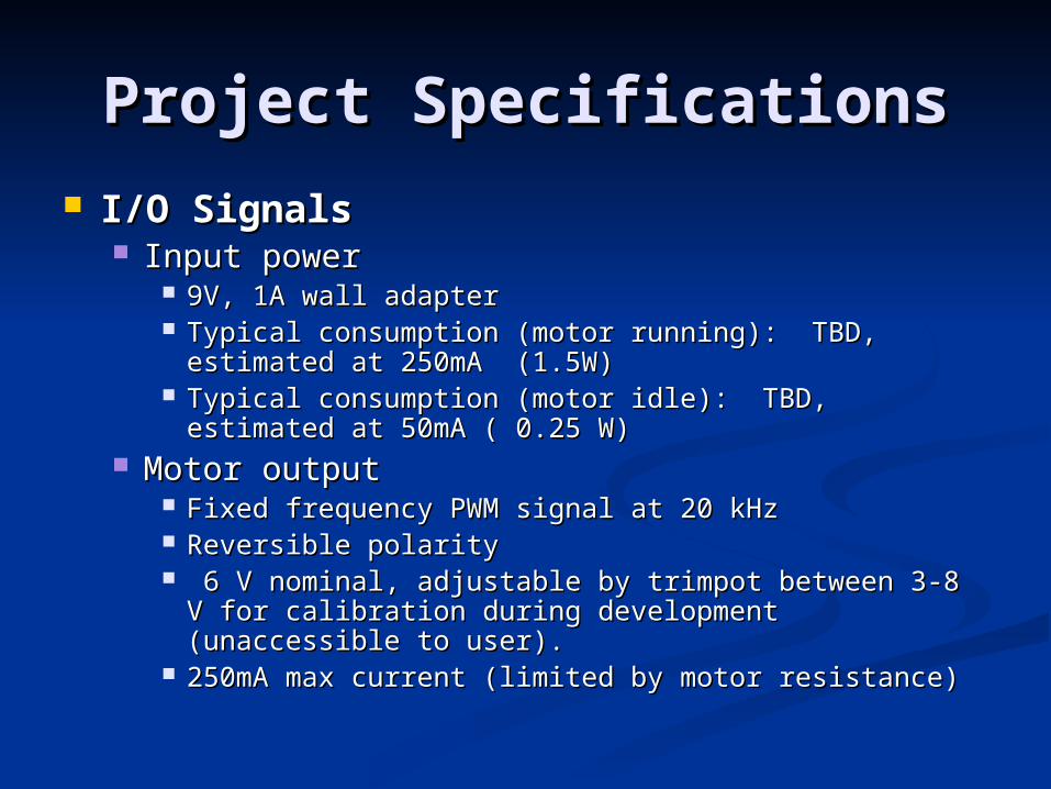
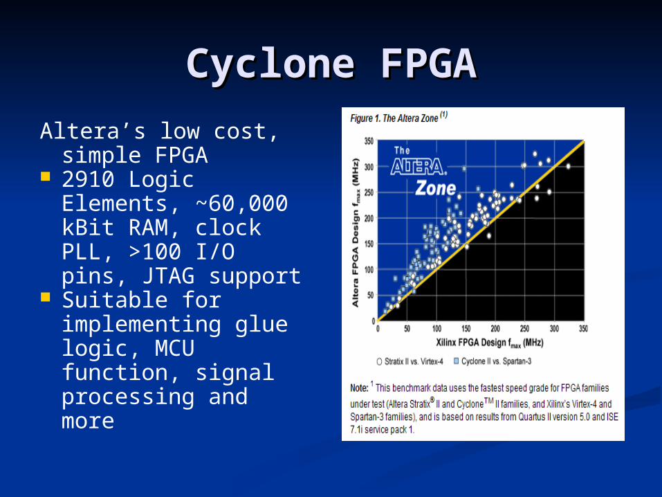
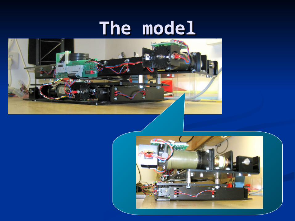
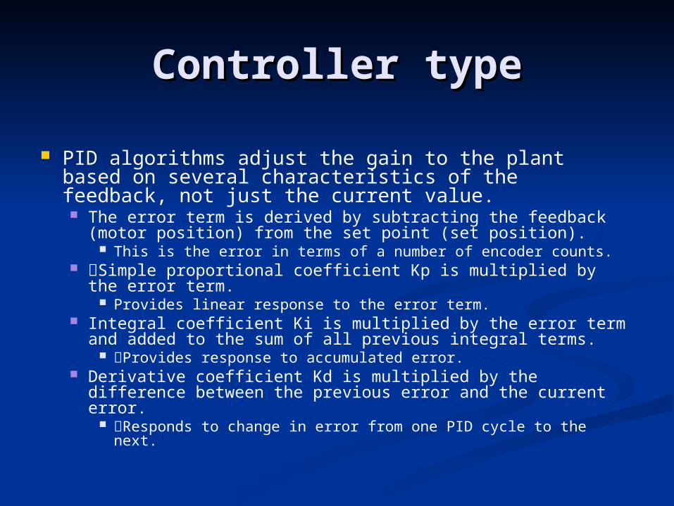
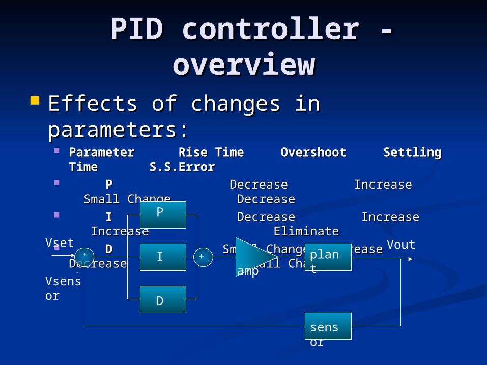
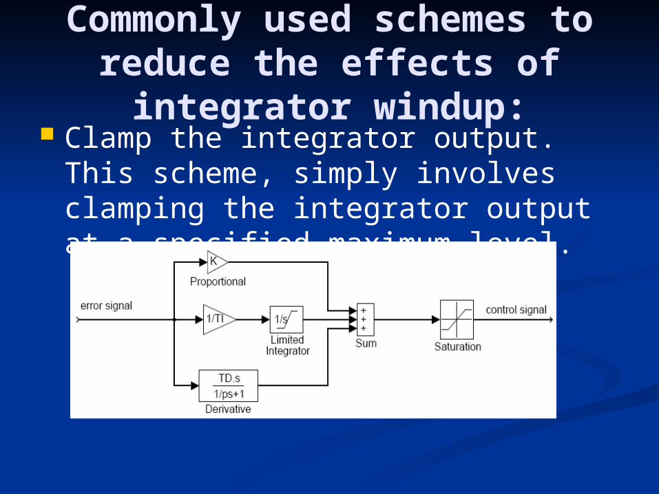
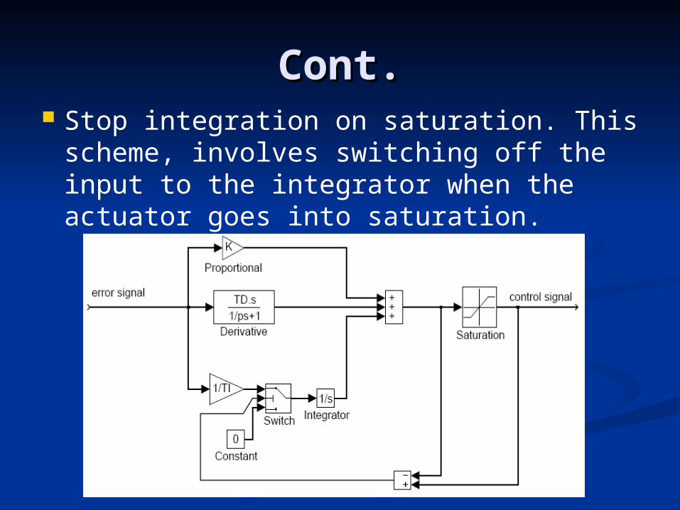
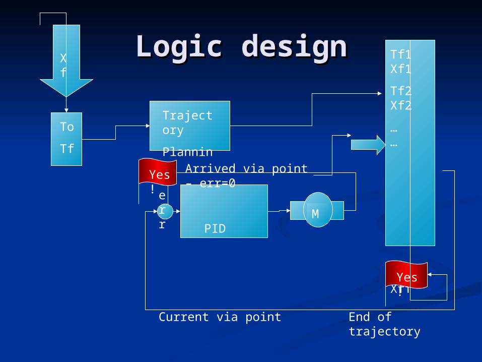

The enDThe enD