
DIFFERENTIAL BASED HEADLIGHT SYSTEM.doc
44
DEPARTMENT OF MECHANICAL ENGINEERING DIFFERENTIAL BASED HEADLIGHT SYSTEM SUBMITTED BY 1 | Page
-
Upload
pandyamech -
Category
Documents
-
view
79 -
download
8
description
this a differntial based headlight system with advanced features
Transcript of DIFFERENTIAL BASED HEADLIGHT SYSTEM.doc

DEPARTMENT OF MECHANICAL ENGINEERING
DIFFERENTIAL BASED HEADLIGHT
SYSTEM
SUBMITTED BY
1 | P a g e

ABSTRACT
Our project is to make new and modern “Directional Headlights” in efficient
manner by increasing the light angle. Directional headlights are those headlights
that provide improved lighting especially for cornering. There are automobiles
that have their headlights directly connected to the steering mechanism so that
its lights will follow the movement of the front wheels.
Our project comprises Cam and Follower mechanism, Gear mechanism and
spring mechanism. Cam and Follower mechanism is used to turn the head lights
to right or left direction, Gear mechanism is used to transmit motion and to
reduce the no of rotations from steering rod to cam shaft. Spring mechanism is
used to bring back the follower and head light bracket to its initial position.
According to our project, when the steering steers to the right, the light bracket
at right alone steers to right using cam & follower mechanism and reduction
gears & vice versa. At the same time the left bracket remains stand still due to
the dwell period of the cam. During the return stroke of cam, the spring
mechanism is used to bring the bracket and follower to its initial position. The
2 | P a g e

reduction gears are used to turn the brackets to the required angle respective to
the steering rotation.
Our project will be useful for vehicles, which are been used in hill
areas
3 | P a g e

1. INTRODUCTION
4 | P a g e

The present invention relates to headlights of an automobile, more particularly to a
direction turning device for headlights of an automobile which enables to turn direction
synchronously with the rotation of the steering and hence increasing the safety for driving
at night or in the darkness.
In the known technology of the prior art, a headlight of an automobile has a
fixed line of emission which is aligned with the front direction of the automobile.
Although the effects of "high beam" or "low beam" can be achieved by adjusting the
angle of elevation of the headlight, the direction of emission is not adjustable as to the
left or right. When the road curves or turns, the corner on time when the car turns,
thereby creating a dead angle of illumination and such lack of visibility poses danger in
driving at night or in darkness.
Therefore, it is highly desirable to invent a device to solve this problem and
such device is of high utility.
An object of the present invention is to provide a direction turning device for a
headlight of an automobile which renders to emission direction of a headlight of an
automobile in synchronization with steering and thus increases the illuminated area upon
changes of direction of the automobile when the automobile makes turns.
In ancient Directional headlights, When the steering steers to right or left
direction, then both the right and left headlights will steer to the perspective directions. It
5 | P a g e

results in altering the optical axis of the head light to the vehicle speed and the front road-
shape.
But according to our project, when the steering steers to right then the right
side of the headlight bracket steers to right side and the left side headlight bracket
remains stationery by cam mechanism and it is similar for the other side also. Because of
this, the optical axis of the headlight is widened and it is useful for the drivers for safety
ride.
6 | P a g e

2. LITERATURE REVIEW
7 | P a g e
Our mechanism is not used elsewhere in any of the vehicles. We
performed a survey on this project with the lorry drivers, who travel to hill
stations often. Based on their queries, we had indulged in this project.
The present invention relates to a vehicle front lamp light distribution
control system and more particularly to a vehicle front lamp light
distribution control system capable of raising visibility at the time of
cornering by controlling light distribution means of the front lamp.
According to Japanese Patent Publication No. H5-23216, Japanese Patent
Application Laid-Open No. H8-183385, Japanese Patent Application Laid-
Open No. H11-78675 and Japanese Patent Application Laid-Open No. H8-
192674 a vehicle head lamp including a fog lamp is provided with a
movable reflector and by turning the movable reflector in the steering
direction by an amount corresponding to a steering angle of the steering
wheel, the light distribution pattern of the front lamp is changed in the
direction of vehicle's turn so as to raise visibility at the time of cornering.
8 | P a g e

However, according to the aforementioned earlier art, the light distribution
pattern of the front lamp is changed in the steering direction of the steering
wheel by an amount corresponding to the steering angle when the vehicle
turns on an intersection or the like, cornering destination cannot be beamed
brightly enough before operating the steering wheel. Therefore, an art
capable of beaming the cornering destination prior to operation of the
steering wheel has been demanded.
Czech Tatra and 1920s Cadillacs were early implementer of such a
technique, producing in the 1930s a vehicle with a central directional
headlamp. The American 1948 Tucker Sedan was likewise equipped with a
third central headlamp connected mechanically to the steering system. The
1967 French Citroën DS and 1970 Citroën SM were equipped with an
elaborate dynamic headlamp positioning system that adjusted the
headlamps' horizontal and vertical positioning in response to inputs from
the vehicle's steering and suspension systems, though US regulations
required this system to be deleted from those models when sold in the
USA.
9 | P a g e

3. CONSTRUCTION
10 | P a g e

The main components used in this project are:
3.1 Spur Gears:
Spur gears are the simplest, and probably most common, type of gear. Their
general form is a cylinder or disk.
The teeth project radially, and with these "straight-cut gears", the leading
edges of the teeth are aligned parallel to the axis of rotation. These gears can
only mesh correctly if they are fitted to parallel axis.
11 | P a g e

3.2 Sprockets:
A sprocket is a profiled wheel with metal teeth that meshes with a chain,
track or other perforated or indented material. Sprockets are used to transmit
rotary motion between two shafts where gears are unsuitable or to impart
linear motion to a track, tape etc.
12 | P a g e

3.3 Cam & follower:
Cams are basically shaped surfaces that are typically not round
follower(possibly a small wheel) is displaced as it moves over the surface.
13 | P a g e

3.4 Steering system:
The most conventional steering arrangement is to turn the front wheels using
a handle operated steering wheel which is positioned in front of the driver,
via the steering column, which may contain universal joints to allow it to
deviate somewhat from a straight line. Other arrangements are sometimes
found on different types of vehicles, for example, a tiller or rear wheel
steering. Tracked vehicles such as tanks usually employ differential steering
that is, the tracks are made to move at different speeds or even in opposite
directions to bring about a change of course.
14 | P a g e

3.5 Light bracket:
Headlamps must be kept in proper alignment (or "aim"). Regulations for aim
vary from country to country and
From beam specification to beam specification. This gives all vehicles
roughly equal seeing distance and all drivers roughly equal glare.
15 | P a g e

3.6 Frames
Framing, in construction known as light frame construction, is a building
technique based around structural members, usually called studs, which
provide a stable frame to which interior and exterior wall coverings are
attached, and covered by a roof comprising horizontal joists and sloping
rafters or manufactured roof trusses covered by various sheathing materials.
Light frame material dimensions range from 38 mm by 89 mm (1.5 by 3.5
inches — i.e. a two-by-four) to 5 cm by 30 cm (two-by-twelve inches) at the
cross-section, and lengths ranging from 2.5 m (8 feet) for walls to 7 m (20
feet) or more for joists and rafters.
16 | P a g e

3.7 Chain drive:
Commonly, mechanical energy from a motor or other source applied to a
sprocket wheel is conveyed by means of an endless chain to another
sprocket wheel for driving a mechanism. Examples of such an arrangement
are found in bicycles, motorcycles, and conveyor belts.
The chain in this application is so designed that each consecutive link fits
over a sprocket, the distance between links being called the pitch. The
relative speed of the wheels varies according to their relative circumferences
and, thus, the number of sprockets on each.
17 | P a g e

4. WORKING METHODOLOGY
18 | P a g e
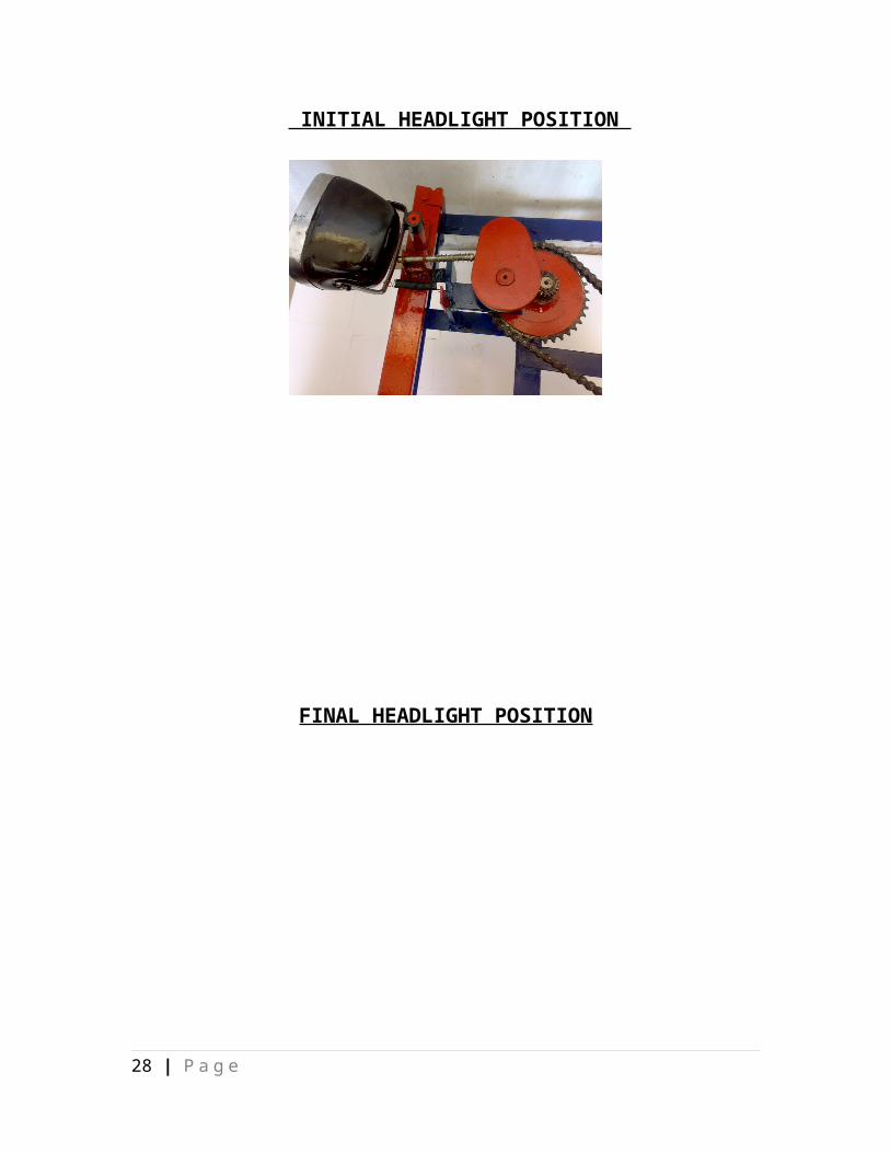
Our project is to the turn the right light bracket to the right, when the vehicle
turns to right leaving the left bracket to remain in standstill position, and
vice versa.
When the steering steers to the right, a sprocket attached to the steering rod
rotates which in turn connected to the other sprocket through a chain. The
sizes of the sprockets were designed in such a way that, if the smaller
sprocket rotates four full complete rotations the larger sprocket will rotate
once. Also the small gear, which is attached to the same shaft as of the
larger sprocket, also rotates along with the sprocket.
A larger gear of the former is chosen, which is twice its diameter, is meshed
to transmit the motion. After this, the rotation of cam is achieved by fixing
the cam in the same shaft of the larger gear. The spherical edged follower is
attached to the cam is used to convert the rotary motion of cam into
reciprocating motion. So the right light bracket moves according to the
movement of the follower. At the same time, the cam at the other end
19 | P a g e

remains in the dwell period, which results in the stand still position of the
light bracket.
The light bracket will returns back to its original position, using the spring
mechanism attached to it.
When the vehicle turns to left, the left bracket alone turns to the left leaving
the right light bracket in standstill position.
20 | P a g e

INITIAL HEADLIGHT POSITION
FINAL HEADLIGHT POSITION
21 | P a g e

5. DESIGN CALCULATIONS
22 | P a g e
5.1. Design calculation for chain drive
Speed of rotation, N1 = 1000 rpm
Speed of rotation, N2 = 250 rpm
Centre distance, a = 800 mm
Gear ratio, i = N1/N2 = 4
istd = 4
Teethes, z1 = 20
Teethes, z2 = i * z1 = 80 teeth
Chain pitch, a = (30 – 50) p
a = 30p => p= 26.67 mm =pmax
a = 50p => p= 16 mm =pmin
Standard pitch, p std =25.4 mm
So the chain selected is 16A1-R80-> simplex
Length of chain,
lp = 2ap + (z1+z2)/2+((z2-z1)/2)2/ap
23 | P a g e

ap = ao/p = 800/25.4 = 31.49
lp = (2*31.49)+50+(60/2*3.14)2/31.49
= 115.87
= 116 links
Actual length = no. of links * pitch
= 2946.6 mm
Bearing area = 1.79 mm2
Centre distance, a = ((e+√(e2 -8m))/4)p
e = lp – (z1+z2)/2 = 66
m = ((z2-z1)/(2*3.14))2 = 91.18
a = 66+√(((662 – (8*91.18))/4)p = 801.5 mm
5.2. Design calculation for chain drive
Speed of rotation, N1 = 1000 rpm
Speed of rotation, N2 = 250 rpm
Centre distance, a = 1200 mm
Gear ratio, i = N1/N2 = 4
istd = 4
Teethes, z1 = 20
Teethes, z2 = i * z1 = 80 teethes
24 | P a g e

Chain pitch, a = (30 – 50)p
a = 30p => p= 40 mm =pmax
a = 50p => p= 24 mm =pmin
Standard pitch, p std =25.4 mm
So the chain selected is 16A1-R80-> simplex
Length of chain,
lp = 2ap + (z1+z2)/2+((z2-z1)/2)2/ap
ap = ao/p = 1200/25.4 = 47.24
lp = (2*47.24)+50+(60/2*3.14)2/47.24
= 144.49
= 146 links
Actual length = no. of links * pitch
= 3708.4 mm
Bearing area = 1.79 mm2 Centre distance, a = ((e+√(e2 -8m))/4)p
e = lp – (z1+z2)/2 = 96
m = ((z2-z1)/(2*3.14))2 = 91.18
a = 96+√(((962 – (8*91.18))/4)p
= 1194.5 mm
25 | P a g e

5.3. Rotation reduction ratios
Steering rotation = 7200
Angle of cam to be tilted = 900
So value of angle to be reduced is in ratio 8:1
The reduction between the sprockets is made as 4:1
So the diameter & teeth of the larger sprocket should be four times that of
the smaller
Diameter, d1 = 40 mm
Teethes, z1 = 20
Diameter, d2 = 160 mm
Teethes, z1 = 80
26 | P a g e

5.4. Design calculation for spur gears
Speed of rotation, N1 = 1000 rpm
Speed of rotation, N2 = 500 rpm
Gear ratio, i = N1/N2 = 2
Assuming the same material for pinion and gear
16Ni 1 Cr80
Life of gear = 20,000 hours
Number of cycles = 20,000*60*N1
= 20,000*60*1000
= 1.2*109 cycles
Young’s modulus, E = 2.15*106 kgf/cm2
= 2.15*105 N/mm2
Design contact stress, [σc] = CR * HRC*Kcl
CR = 310, HRC = 60, Kcl= 1 {from psg tech data book pg.No.8.17}
[σc] = 18.6 * 102 N/mm2
Design bending stress, [σb] = ((1.4*Kbl*σ-1)/(n*Kσ))
27 | P a g e
N = 2, Kσ = 1.2, Kbl = 1
σ-1 = 0.25σu + 1200
σu = 1000 N/mm2
σ-1 = 47000 N/cm2
[σb] = 274.16 N/mm2
k.kd = 1.3
ko = 1.5(medium shock)
Teethes, z1 = 20
Teethes, z2= i*z1 = 40
28 | P a g e

5.5. Design calculation for sprockets
Here the rotation reduction ratio is 4:1
So the diameter & teeth of larger sprocket should be four times that of the
smaller.
Diameter, d1 = 40 mm [readily available in market]
Teethes, z1 = 20
Diameter, d2 = 160 mm
Teethes, z2 = 80
29 | P a g e

5.6. Design calculation for cam & follower
OA = initial position of light bracket (7inches)
AB = final position of light bracket
OB = distance moved by the bracket
Stroke length = 102.6 mm
Cam diameter = 150 mm
Follower length = 102.6 mm
30 | P a g e

5.7. Sprocket & Gear details, we selected due to availability in market:
S.No. Component Material No. of teethes Diameter
1. Small Sprocket Mild steel 20 40
2. Large Sprocket Mild steel 80 160
3. Small Gear Mild steel 20 40
4. Large Gear Mild steel 40 80
31 | P a g e

6. RESULT & FUTURE APPLICATIONS
32 | P a g e

6.1 ADVANTAGES
Useful for heavy vehicles in hill areas, where hair-pin bends are more.
Safe riding
Accident free roads
Simple in structure
Mind free driving
6.2 LIMITATIONS
Not mandatory for straight roads.
6.3 APPLICATIONS
Can be used in all heavy vehicles.
Can be used in tempo and vans.
33 | P a g e

7. BIBLIOGRAPHY
1. Book on “Design of Machine Elements” by K.V.NATARAJAN
2. Book on “Design of Transmission Systems” by V.BANDARI
3. PSG Design Data Book.
4. www.wikipedia.com
34 | P a g e