Differences Between Steel Wire and Synthetic Rope ...
84
Joona Stenman Differences Between Steel Wire and Synthetic Rope Reliability in Hoisting Applications Master’s thesis submitted in partial fulfilment of the require- ments for the degree of Master of Science in Technology. In Espoo 20.11.2020 Supervisor: Professor Kevin Otto Advisor: D.Sc. (Tech.) Kirsi Saarinen-Pulli
Transcript of Differences Between Steel Wire and Synthetic Rope ...

Joona Stenman
Differences Between Steel Wire and Synthetic Rope Reliability in Hoisting Applications
Master’s thesis submitted in partial fulfilment of the require-ments for the degree of Master of Science in Technology. In Espoo 20.11.2020 Supervisor: Professor Kevin Otto Advisor: D.Sc. (Tech.) Kirsi Saarinen-Pulli
Aalto University, P.O. BOX 11000, 00076 AALTO
www.aalto.fi
Abstract of master's thesis
Author Joona Stenman
Title of thesis Differences Between Steel Wire and Synthetic Rope Reliability in Hoist-
ing Applications
Master programme Mechanical Engineering Code ENG25
Thesis supervisor Professor Kevin Otto
Thesis advisor D.Sc. (Tech.) Kirsi Saarinen-Pulli
Date 20.11.2020 Number of pages 72+5 Language English
Abstract
The focus of this master’s thesis was researching rope failures in hoisting applications. In this thesis, the mechanics of steel wire rope and synthetic rope failure were researched, and the reasons for rope replacements made in the field were analysed. Synthetic rope is a rather new product in hoisting applications. Therefore, comprehensive field data was not available. By analysing steel wire rope failures in the field together with the effect of hoist frame sizes and usage profile on failure modes, the kind of failures that occur with synthetic rope were estimated. Identifying typical failure modes and their root causes en-sures successful inspection of synthetic rope and, thus, safe usage.
The target company’s maintenance data concerning steel wire rope failures in customer devices was utilized in this master’s thesis. This information was statistically analysed by identifying and categorizing occurred failure modes. Researched hoists were divided into three groups based on their model. In these model groups, hoists were categorized into smaller groups based on their frame size and capacity. The target company’s rope failure reports and authority accident reports were used to analyse the causes of rope failure.
From service data it is seen that the major failure modes of steel wire ropes are rope deformations and broken wires. Deformations are typically caused by abnormal usage. Broken wires are caused by natural fatigue when the rope is bent over the sheaves during lifting movement. Based on field data, a trend is detected that deformations caused by abnormal usage are more common in workshop than process usage hoists, and their share increases when hoist frame size decreases. From rope failure reports, it is seen that the most significant causes are misuse or either failed or neglected inspection. Risks of syn-thetic rope failure and their occurrence were identified by failure mode, effects and criti-cality analysis. For the most essential found failure modes, root cause analysis was per-formed to identify and minimize factors causing damage. Internal wear of rope, broken rope by cut and decreased load bearing capacity caused by high temperatures are identi-fied as the most critical failure modes for synthetic rope in the field. Research shall be continued by developing failure detection techniques for synthetic rope inspections, such as how to detect ropes exposed to high temperatures, UV radiation or shock loads. In the future, the target company’s field data should be developed so that more accurate analyses can be performed, and failure mode, effect and criticality analysis can be updated to correspond to real failure modes and their occurrence in the field.
Keywords reliability, steel wire rope, synthetic rope, failure modes

Aalto-yliopisto, PL 11000, 00076 AALTO
www.aalto.fi
Diplomityön tiivistelmä
Tekijä Joona Stenman
Työn nimi Teräksisen ja synteettisen köyden luotettavuuden vertailu nostinsovelluk-
sissa
Maisteriohjelma Mechanical Engineering Koodi ENG25
Työn valvoja Professori Kevin Otto
Työn ohjaaja TkT Kirsi Saarinen-Pulli
Päivämäärä 20.11.2020 Sivumäärä 72+5 Kieli Englanti
Tiivistelmä
Diplomityö keskittyi tutkimaan köysien vikaantumista nostinlaitteissa. Työssä tutkittiin kuinka teräksinen ja synteettinen nostoköysi vikaantuivat ja analysoitiin kentällä toteu-tuneiden köydenvaihtojen syitä. Koska synteettinen köysi on verrattain uusi tuote nostin-sovelluksissa, siitä ei ollut saatavilla kattavasti kenttädataa. Analysoimalla teräsköyden vikaantumisia kentällä sekä nostimen kokoluokan ja käyttöprofiilin vaikutusta vikamuo-toihin pyrittiin arvioimaan, millaisia vikamuotoja synteettisellä köydellä voidaan olettaa ilmaantuvan. Tyypillisten vikamuotojen ja niiden juurisyiden tunteminen mahdollistaa synteettisen köyden onnistuneen tarkastamisen ja näin turvallisen käytön.
Diplomityössä käytettiin kohdeyrityksen huoltotoiminnan tuottamaa dataa teräs-köysien vikaantumisista asiakkaiden laitteissa. Tätä tietoa sovellettiin tilastollisen ana-lyysin avulla tunnistamalla ja jaottelemalla esiintyneet teräsköysien vikamuodot. Tutkitut nostimet jaettiin kolmeen ryhmään mallisarjaan perustuen. Mallisarjan sisällä nostimet jaoteltiin runkokoon ja kapasiteetin mukaan pienempiin ryhmiin. Kohdeyrityksen köy-den vikaantumisraporttien sekä viranomaisen onnettomuusraporttien avulla analysoitiin myös syitä, jotka johtivat köyden vikaantumiseen.
Huoltotoiminnan datasta havaitaan teräsköysien hallitseviksi vikamuodoiksi köyden muodonmuutokset ja lankakatkot. Muodonmuutokset johtuvat tyypillisesti epänormaa-lista käytöstä. Lankakatkoja köyteen muodostuu luonnollisesta väsymisestä, kun köyttä taivutetaan köysipyörien ympäri nostoliikkeen aikana. Kenttädataan perustuen havaitaan trendi, jonka mukaan epänormaalista käytöstä johtuvat muodonmuutokset ovat tyypilli-sempiä työpaja- kuin prosessikäytössä olevissa laitteissa, ja niiden osuus kasvaa, kun lait-teiden runkokoko pienenee. Köysien vikaantumisraporteista havaitaan merkittävimmiksi kuorman putoamisen aiheuttajiksi väärinkäytöt sekä laiminlyöty tai epäonnistunut tar-kastus. Synteettisen köyden vikamuotojen esiintyvyyttä ja riskejä tunnistettiin vika-muoto, vaikutus ja vakavuus -analyysin avulla. Kaikkein oleellisimmille löydetyille vika-muodoille tehtiin lisäksi juurisyyanalyysi, jotta mahdolliset vioittumiselle altistavat teki-jät voidaan tunnistaa ja minimoida. Havaitaan, että kentällä synteettiselle köydelle kriit-tisimpiä riskejä ovat köyden sisäinen kuluminen, leikkautumisesta johtuva katkeaminen ja korkean lämpötilan aiheuttama kantokyvyn aleneminen. Tutkimusta tulee jatkaa synteettisen köyden vikaantumisen havaitsemiskeinoja kehit-tämällä, kuten miten korkeille lämpötiloille, UV-säteilylle tai sokkikuormalle altistunut köysi voidaan tunnistaa tarkastuksessa. Jatkossa kohdeyrityksen keräämää kenttädataa tulee kehittää, jotta tulevaisuudessa voidaan tehdä tarkempia analyysejä ja vikamuoto, vaikutus ja vakavuus -analyysia voidaan päivittää vastaamaan todellisia kentällä ilmene-viä vikamuotoja ja niiden ilmaantuvuutta.
Avainsanat luotettavuus, teräsköysi, synteettinen köysi, vikaantuminen

Aalto-yliopisto, PL 11000, 00076 AALTO
www.aalto.fi
Diplomityön tiivistelmä
Preface This thesis is written for the target company’s research and testing department as a con-tinuum of series of master’s theses regarding overhead crane component reliability. Syn-thetic rope is considered a new product in the field of overhead cranes, and it has become an alternative for steel wire rope. This thesis was an opportunity to create research infor-mation on how to ensure safety and reliability of synthetic rope in the field. As the last step of my university studies, this thesis has given me a great opportunity to dive into an interesting topic, extend my knowledge and tie together the end of my university studies and the beginning of my professional career. I personally want to thank my advisor, Kirsi Saarinen-Pulli, for her professional guidance and Juha Sunio for sharing his knowledge and commenting on my work. I also want to thank my supervisor, Kevin Otto, from Aalto University for guiding me through the completion of this thesis. Special mentions belong to my parents for supporting me through all these years and to Alisa for supporting me at home, without forgetting all of my friends for providing unforgettable experiences and colleagues for providing professional guidance and advice. Espoo 27.10.2020
Joona Stenman

i
Table of Contents Abstract Tiivistelmä Preface Table of Contents .................................................................................................................... i Abbreviations ........................................................................................................................ iii 1 Introduction .................................................................................................................... 1
2 Rope ............................................................................................................................... 3
2.1 Rope in hoisting applications .................................................................................. 3
2.2 Steel wire rope ......................................................................................................... 4
2.3 Synthetic rope .......................................................................................................... 7
3 Reliability of rope ........................................................................................................ 10
3.1 Factors affecting rope lifetime .............................................................................. 12
3.1.1 Hoist structure ................................................................................................ 13
3.1.2 Hoist usage ..................................................................................................... 13
3.1.3 Usage environment ........................................................................................ 15
3.2 Inspection .............................................................................................................. 15
3.2.1 Steel wire rope ............................................................................................... 16
3.2.2 Synthetic rope ................................................................................................ 24
4 Research data ............................................................................................................... 31
4.1 Incident investigations .......................................................................................... 31
4.1.1 Subject company incident reports .................................................................. 32
4.1.2 Occupational Safety and Health Organization accident reports .................... 32
4.2 Field service data ................................................................................................... 33
4.3 Failure mode, effects and criticality analysis ........................................................ 34
4.4 Root cause analysis ............................................................................................... 36
4.5 Data uncertainty .................................................................................................... 36
4.5.1 Incident reports .............................................................................................. 36
4.5.2 Field service data ........................................................................................... 36
4.5.3 FMECA and RCA .......................................................................................... 37
5 Incident investigations ................................................................................................. 38
5.1 Target company’s rope failure reports .................................................................. 38
5.2 OSHA accident reports ......................................................................................... 39
6 Rope failures in field service data ................................................................................ 40
6.1 Hoist model A ....................................................................................................... 40
6.1.1 Frame size 1 ................................................................................................... 42
6.1.2 Frame size 2 ................................................................................................... 43
6.1.3 Frame size 3 ................................................................................................... 44
6.1.4 Frame size 4 ................................................................................................... 45
6.1.5 Hoist model A rope replacement conclusions ............................................... 46
6.2 Hoist model B ....................................................................................................... 47
6.2.1 Frame size 1 ................................................................................................... 49
6.2.2 Frame size 2 ................................................................................................... 50
6.2.3 Frame size 3 ................................................................................................... 51
6.2.4 Hoist model B rope replacement conclusions ................................................ 52
6.3 Hoist model C ....................................................................................................... 52
6.3.1 Capacity range 1 ............................................................................................ 54

ii
6.3.2 Capacity range 2 ............................................................................................ 55
6.3.3 Hoist model C rope replacement conclusions ................................................ 56
7 Analysing reliability .................................................................................................... 58
7.1 Rope replacements with steel wire rope ................................................................ 58
7.2 Synthetic rope failure mode, effects and criticality analysis ................................. 61
7.3 Ensuring the reliability and safety of synthetic rope ............................................. 63
7.4 Differences from the reliability and safety perspective ........................................ 64
8 Conclusions .................................................................................................................. 67
9 References .................................................................................................................... 69
10 List of appendices ........................................................................................................ 72
Appendices
iii
Abbreviations FMEA Failure Mode and Effects Analysis FMECA Failure Mode, Effects and Criticality Analysis HMPE High Modular Polyethylene IWRC Independent Wire Rope Core LCP Liquid Crystal Polymer MBL Minimum Breaking Load MRI Magnetic Rope Inspection NDT Non-Destructive Testing RCA Root Cause Analysis RPN Risk Priority Number UHMWPE Ultra-High-Molecular-Weight Polyethylene WLL Working Load Limit
1
1 Introduction Reliability is the probability of how confidently a system or a component fulfils its required function in a period of time. When the component or the system does not fulfil its required function, it is considered failed (O’Connor and Kleyner, 2012). For example, in the crane industry, a crane is considered failed when it can still lift a load, but not its nominal load. The examination of the reliability of a large, complex system, such as a hoist, is a challenging task. Therefore, dividing it into components and examining the reliability of those compo-nents and gathering that information to combine into larger system level reliability is a rea-sonable approach. Hoist reliability has been studied earlier on the component level through motors (Pynnönen, 2019) and brakes (Valli, 2015). Environmental conditions as a factor of reliability (Linnainmaa, 2014), taking advantage of field data (Röksä, 2015), considering reliability in the design phase (Peltoranta, 2014) and how collected data and digital twins can be exploited (Anthoni, 2018) are also significant sources of knowledge when consider-ing hoist reliability. A crane is usually a significant part of production processes and facilities. It might be located in a production line or in a storing area. Lifting and transporting loads are the main functions of a crane. The crane is a large system, which can move a load into all three directions. The hoist is a part of the crane and takes care of lifting the load. In this master’s thesis, only the hoist is considered since it is the most complex part of the crane and lifting is the most critical action. In hoisting, the rope is a critical part of safety and reliability. The most serious con-sequence of rope failure is a load drop, which may cause fatalities or at least material dam-ages. An unreliable product causes fluctuating expenses to manufacturers during the war-ranty period, and even after the warranty period, an unreliable product can damage the rep-utation of the manufacturer and affect further sales (O’Connor and Kleyner, 2012). Alto-gether, unpredicted failures are the cause of offending downtime for crane operation, which is usually expensive in a production environment. As a part of ensuring safe operation of the crane and preventing expensive downtime, run-to-failure maintenance is not a suitable maintenance policy for the hoisting rope. In run-to-failure maintenance, a component is only replaced when it fails. A failing rope causes unac-ceptable health and material risks. Therefore, the rope must be replaced before the end of its lifetime. Misuse can damage the rope, and the rope must be replaced right after failure and only then can regular operation continue. However, replacing the rope early, before the end of its lifetime, causes extra expenses. Knowing the lifetime of the rope is a key factor when balancing between cost efficiency and safety. Knowing the lifetime of the rope in certain applications is a challenging reliability engineering task, where understanding failure mech-anisms, testing and rope lifetime data is needed. The inspection of the rope is a critical step where the inspector decides whether to continue with the rope until next the inspection or discard the rope and replace it. The likelihood of noticing the reduced lifetime of the rope plays an important role. If the rope has low inspectability, the rope’s reliability decreases because possible failures are not noticed. Therefore, both rope reliability and inspectability are important topics. By performing tests on a product, data from failure modes and time before failure is gathered. In this work, the first goal is defining these rope failure modes for both steel wire and syn-thetic rope using literature. By using the target company’s field service data, rope failure
2
modes occurring in the field are researched. This is the second goal of this study. Based on knowledge gained from the first and the second goal, approaches to control synthetic rope reliability are established. This includes failure mode, effects and criticality analysis and root cause analysis for synthetic rope. The synthetic rope, as an alternative to steel wire rope, is a new component in hoisting applications and, therefore, its reliability requires research. In tower crane industry, Liebherr provides synthetic fibre rope for tower cranes, promising +20% higher lifting capacity because of the weight reduction of the rope and the hook block and four times the durability compared to traditional rope (Liebherr, 2020). This master’s thesis aims to answer what kind of usage ropes face in the field and what kind of factors must be considered when using synthetic rope instead of steel wire rope to be able to control rope reliability. The goal is also to find what kind of failure modes are relevant to synthetic rope in the field. New synthetic rope materials are entering the market parallel to steel wire ropes. Thus, a new component is being formed and not enough reliability data is yet available. To summarize, the main research questions to be answered in order to increase rope reliability and safety are the following:
What kind of rope failures occur with steel wire and synthetic rope? How do failure modes deviate between synthetic and steel wire ropes? What should be considered when shifting from steel wire rope to synthetic rope to
ensure safety?
A hoist rope is inspected after a certain time interval. To be reliable, hoisting ropes should wear out evenly and failure modes should be recognizable. The inspection period should be defined depending on use. During an inspection, signs of fatigue, misuse and uneven wear are looked for. Overloading, shock loading or side pulling are typical examples of misuse that cause rope deterioration and are also important to detect. Improper installation, such as leaving a large amount of twist, can also cause these deterioration symptoms. Neglecting inspections can cause safety hazards and reduce the lifetime of the rope. Therefore, control-ling all these factors is the key to achieving high reliability. From an application perspective, this research focuses on ropes used in hoisting applications. Hoisting is considered as lifting objects, but not humans. Therefore, this thesis is not con-cerned with lift ropes. For hoisting ropes, steel wire and synthetic are the two types of rope considered. Other possible hoisting rope compensators, such as belts or chains, are not a concern. In section two, the rope is introduced. Both steel wire rope and synthetic material ropes are considered. They are a concern from the perspective of hoisting applications. In the third section, rope reliability is discussed and what kind of aspects rope reliability has when con-cerning rope safety. Rope inspections and factors affecting rope lifetime are a key part of this section. Later, the target company’s field data as well as rope failure reports are intro-duced and analysed. Based on the findings from the data and literature review, analyses of synthetic rope usage in the field are made. Differences between steel wire and synthetic rope are also explored as well as what should be considered from the perspective of reliability and safety when shifting from steel wire to synthetic rope.

3
2 Rope In this section, rope and how it is used in hoisting applications is discussed. In this thesis, rope and its applications involve only hoisting. The rope, as an old and rather straightforward component, can be used in many other applications as well. The hoist as part of a crane and rope installation geometry, or reeving, are introduced. Commonly known basic types of steel wire and synthetic rope are also introduced. All of the above is relevant information for further understanding rope reliability, inspection and failure modes.
2.1 Rope in hoisting applications In this subsection, the rope is considered from the point of view of working as a hoisting medium. The hoist together with the reeving and how the rope moves in the hoist is intro-duced. According to the ISO 14492 definition, the hoist is a machine for lifting and lowering loads. The hoist uses the rope to connect a lifted load to the hoisting machinery. Therefore, the rope is one of the safety critical components in the hoist. Selecting a suitable rope for the hoist medium is not a simple task. The rope shall be particularly designed for hoisting tasks to handle operational stresses. It also has to have a longer service period than the rope-spec-ified inspection interval. (Finnish Standards Association, 2019b) In a hoist, as seen in Figure 1, the rope is rotated around the drum. When the drum is rotated, the amount of rope hanging increases or decreases. The hook block attached to the rope is lifted or lowered. With this simple mechanism, the hoist converts the rotation movement of the drum to the vertical movement of the hook block. The main components of the hoist are named in Figure 1, where the hoist is installed on a yellow beam.
Figure 1. An electric wire rope hoist, adapted from Hoist Zone (2020)

4
In the simplest case, only one rope comes down from the drum and ends fixed up to a hook block. However, usually the rope comes down to a hook block sheave and heads back up. Up in the hoist, there is a fixed end for the rope. The rope might also have several falls through sheaves. For example, such as the four falls seen in Figure 1. Then the load attached to the hook block is divided between multiple descending ropes. Typically, a rope reeving is represented in the following form: total number of falls, division sign and number of ropes (Industrial Magza, 2020). The reeving of the hoist in Figure 1 is presented as 4/1, which means four falls with one rope. When focusing on a moving rope in a hoist, one way to approach it is to think of it as a flow from a Lagrange approach. In the Lagrange approach, points of flow are marked and the flow is observed by tracking these points and their motion in time. In the same way, the moving rope can be considered from a Lagrange approach. Points of the rope come from the drum and flow downwards to the first lower sheave. They pass through the lower sheave and continue upwards to the upper sheave. The speed of the observed point decreases after each sheave. After the last sheave, the observed point no longer has velocity and stays stationary. Observing moving rope this way is useful when rope lifetime, rope bending and rope failures are in the focus. Depending on the location of the point in the rope, it experiences a different amount of bending. Also, failures in the rope can either be localized in the rope and/or mov-ing along the rope.
2.2 Steel wire rope This section concerns the first of the two types of rope introduced in this thesis. Steel wire rope for hoisting has several varying factors, such as rope material, construction and core type, which have an effect on which kind of use the rope is designed for and how it deterio-rates. Steel wire rope is produced from multiple small steel wires. The wire is the smallest component of the rope. Wires are tied together around a centre wire, producing a strand. Multiple strands are tied together in a helical form around a core. It forms a structure which is then called a rope. This vocabulary is introduced in Figure 2. The rope core can be an independent steel wire strand or made from fibres or plastic. Wire material can be steel, stainless steel or even bronze (Wire Rope Technical Board, 2005). However, according to EN 10264-3, in high-duty applications, steel wire and wire products can be round or shaped high-carbon steel wires with a nominal tensile strength grade of 1 570, 1 770 or 2 160 MPa and with or without a zinc coating (Finnish Standards Association, 2012a).
Figure 2. A wire rope, adapted from Wikimedia Commons (2014)

5
Rope strands are rotated around the rope core in a helical form. The rotation direction of the strands as well as the rotation direction of the wires in the strand are significant when de-signing ropes. Ordinary right and left-hand lays are shown in Figure 3 on the left. In a right-hand lay, strands or wires rotate to the right in the same way as in a right-hand screw. In a left-hand lay, the opposite is true. In the ordinary lay type, strands and wires have opposite lay directions. For example, in Figure 3, in the right-hand ordinary lay, the strands rotate to the right but the wires in the strand rotate to the left. In a lang lay rope, strands and wires rotate in the same direction. Lang lay ropes are vulnerable to unscrewing and as such, they can only be used in hoisting systems where the reeving configuration ensures that the rope cannot unscrew. However, in lang lay ropes, the surface pressure between wires is smaller than in the ordinary lay, which means lang lay ropes have increased flexibility and a longer fatigue lifetime (Wire Rope Technical Board, 2005). In applications where the reeving con-figuration cannot ensure that the rope cannot unscrew, it is necessary to use rotation resistant ropes. These reeving configurations are, for example, single-fall ropes without a guide (Finnish Standards Association, 2019b). In a rotation resistant rope, strand layers alternate so that the direction of the outer strand layers is opposite to the strand layer below (Wire Rope Technical Board, 2005).
Figure 3. Different lay types of rope, adapted from Rotor Cranes (2013)
Together with wire orientation, strand pattern is a significant factor among a rope’s endur-ance characteristics (Wire Rope Technical Board, 2005). Five basic strand patterns are seen in Figure 4. In a single layer strand pattern, all wires are equally thick. In Filler Wire there are several thinner wires to fill gaps between larger wires. In a Seale type strand, larger wires form a closed outer ring and smaller wires form a closed inner ring around a central wire. In a Warrington type strand, there are wires with two different diameters in the outer ring. Slightly smaller and larger wires alternate. The inner ring and the central wire have the same diameter. In a combined strand type, the outer ring is similar to that of a Seale type strand, but a Warrington style ring exists between other wire ring layers. These basic strand patterns can also be combined in other ways, e.g. Seale Filler Wire, where Seale and Filler Wire stand patterns are combined. The rope strand pattern is a significant factor of the rope properties. The rope with a smaller wire diameter is more fatigue resistant and flexible, while the rope with larger wires is more abrasion and crush resistant (Mazzella Companies, 2018).

6
Figure 4. Basic strand patterns (Mazella Companies, 2018)
The core is the component in the centre of the rope that the strands are turned around. The core supports the strands and allows movement under bending and loading. Three main core types are introduced in Figure 5. A fibre core is made from synthetic or natural fibres, such as polypropylene or hemp, and it does not carry a load. In a strand core, there is one strand more than in normal rope construction, and the extra strand works as the core of the rope. In an independent wire rope core, also referred to as IWRC, the core is made from an inde-pendent wire strand. It is more flexible than the strand core and offers better resistance to crushing than the fibre core. (Mazzella Companies, 2018)
Figure 5. Wire rope core types (Vanguard Steel Ltd., 2013)
Steel wire rope is secured to a hoisting system from both ends. On the drum, there are rope clamps to connect the rope to the drum. However, they do not hold a load in normal operation but work as a backup for rope attachment. The steel wire rope is rotated approximately three full rounds before the rope clamps. These are called friction rounds. These rounds carry the load while the rope clamps only secure the rope. The free end of the rope is either attached to a hoist or to a hook block, depending of the hoist system reeving geometry. For steel wire rope, a wedge connection is a way to secure the free end of the rope. In the wedge connection, the rope makes a loop around the wedge and is pushed against the wedge housing walls, as
7
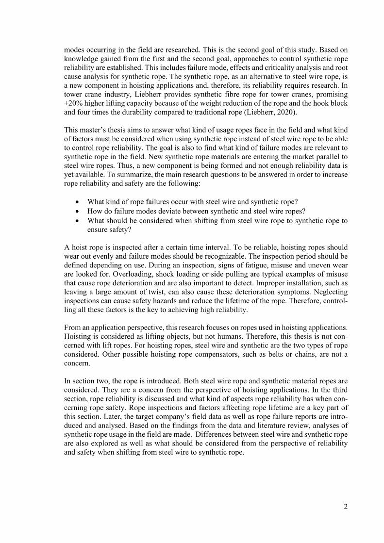
seen in Figure 6. The nature of the wedge connection makes it secure due to rope tension making the wedge connection tighten.
Figure 6. Rope wedge connection (Grofsmederij Nieuwkoop B.V., 2020)
Steel wire rope requires lubrication, which is added during manufacturing but also during maintenance. The lubrication reduces the friction between wires and strands moving along-side each other. The lubrication also protects wire rope from corrosion. Without lubrication, the rope is vulnerable to accelerated wear between the wires and between the rope and the drum or sheaves. (Mazzella Companies, 2018)
2.3 Synthetic rope This section discusses synthetic rope and its use in hoisting applications. Synthetic rope is an alternative for steel wire rope. According to ISO 14492, ropes manufactured from other materials than a steel can be used when the wear conditions and discard criteria are known and recognizable. The design of the drum, sheaves and rope attachments must be considered suitable for synthetic rope. However, replacing steel wire rope with synthetic rope is not allowed in high risk applications. (Finnish Standards Association, 2019b) Synthetic rope as a fibre rope consists of strands made from a synthetic material. These syn-thetic rope fibres consist of polymers, which are long chains of molecules in chemical com-pounds (Finnish Standards Association, 2005). Synthetic ropes used in industrial hoists and winches are selected based on their properties. These properties are high strength, very low elongation, flex fatigue resistance and corrosion resistance, and based on these requirements, suitable materials are (McKenna, Hearle and O’Hear, 2004):
Aramid fibres High modulus polyethylene (HMPE) Liquid crystal polymer (LCP)

8
In this thesis, the analysed hoists using synthetic hoisting rope utilize a rope made of ultra-high molecular weight polyethylene (UHMWPE). In these ropes, load bearing strands or the core is made from continuous filament UHMWPE fibres, also known as high modulus pol-yethylene (HMPE) (Finnish Standards Association, 2018). In the ISO standards 9554 (Fibre ropes, General specifications) and 10325 (Fibre ropes, High modulus polyethylene, 8-strand braided ropes, 12-strand braided ropes and covered ropes), the UHMWPE ropes are catego-rized into high modulus polyethylene ropes. UHMWPE has high strength, low coefficient of friction, low wear and high chemical resistance (Fu, Jin and Wang, 2019). Because of these properties, UHMWPE has been used in biomedical applications since the early 1960s in, for example, hip and knee joints (Fu, Jin and Wang, 2019). A fibre rope consists of the fibre itself, also called filaments. In some larger ropes, the fila-ments are braided together and they form yarn. A group of filaments or yarns form a strand. Strands are braided into the form of a rope. This is seen in Figure 7. The rotation direction in yarns and strands is named the same way as with steel wire ropes into a right-hand lay, also called a Z-twist, and a left-hand lay, also called an S-twist. An equal amount of Z and S-strands formed by filaments alternate in braided rope, forming a torque-balanced structure (Samson Rope Technologies, 2018). The vocabulary used in this thesis is seen in Figure 7. In a different context or based on manufacturer’s own naming system, the vocabulary of fibre ropes may vary.
Figure 7. A braided fibre rope structure, adapted from Finnish Standards Association (2018)
8 and 12-strand hollow single-braid construction is used with the full range of different rope materials. Number eight or twelve in rope construction naturally defines the number of strands. The single braid defines that the rope is braided as a single piece and does not have several separate layers. The name “hollow” comes from the rope centre being hollow. This feature can be seen when the rope is squeezed in the axis direction of the rope. The hollow single-braid rope is balanced by its nature, having an equal amount of S and Z-strands, and will not rotate under a load. In this section, hollow single-braid ropes are covered from the perspective of the UHMWPE ropes. For the UHMWPE ropes, it is necessary to use a rather long pitch length, which gives the rope its softness. Generally hollow single-braid ropes have higher strength and less stretch compared to other laid and plaited rope constructions. How-ever, it suffers more internal wear compared to these other rope constructions under loading and unloading cycles. (McKenna, Hearle and O’Hear, 2004) Braided UHMWPE ropes with a jacket construction are for an environment where a cover for external wear is required. The braided rope core under the jacket carries the load and is typically hollow braided or plaited. The cover jacket is typically made from polyester and is relatively thick to protect the core from cuts and external wear. (McKenna, Hearle and O’Hear, 2004)

9
Synthetic rope forms an eye loop for rope termination and further attachment. The rope is tucked through itself, and its tail is buried into the hollow centre of the rope. The formed eye loop is rather straightforward to install on a hoist. A long burying length makes the splice reliable for cyclic loading (McKenna, Hearle and O’Hear, 2004). However, to ensure a reli-able splice with a shorter burying length, tucking, as seen in Figure 8, is used together with burying. As seen in the figure, synthetic rope structure allows for threading the rope through itself. This is not possible with steel wire rope because it resists opening up the rope structure and the core to avoid splitting the rope through the middle. The eye loop is used instead of a wedge connection to prevent the rope from being cut away from the connection.
Figure 8. 12-strand hollow braid rope termination loop before tightening (McKenna, Hearle and O’Hear,
2004)
10
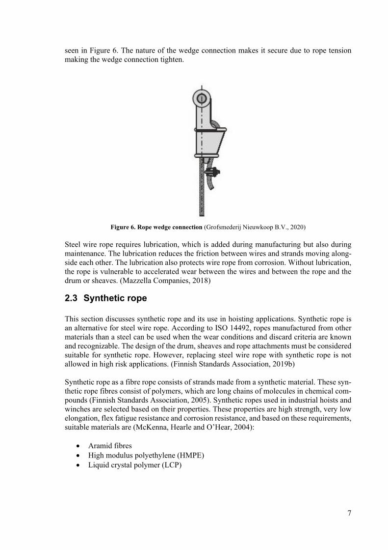
3 Reliability of rope This section concerns the reliability of hoisting rope. Reliability is a characteristic of a com-ponent. It is the probability that a component will perform its defined function without failure under specified conditions and time (O’Connor and Kleyner, 2012). For hoisting rope, this means performing lifting, lowering and hanging tasks without failure. Failure is determined as deterioration of the rope or the rope reaching a discard criterion. Good reliability is formed from low variation in component failure time, from being able to know and predict a failure mode and from being able to see the oncoming failure in an inspection. Therefore, inspec-tions and failure modes form the frame of this section of the thesis. Safety is determined as the component not causing injury to persons, damaging materials and not having other un-acceptable consequences during operation or after a failure (Birolini, 2010). High reliability means that the component is unlikely to fail before its predicted lifetime. Failure would com-promise safety. Knowing the relevant failure modes, detecting them in an inspection and finding the root cause improves safety and availability. Thus, excepted failures can be pre-vented without compromising the safety and maintenance processes can be optimized, and, therefore, life-cycle costs are reduced (Tinga, 2013). An important aspect in rope reliability prediction is identifying failure modes and also iden-tifying why they happen. This is a key factor in being able to be aware of what kind of failure modes and changes in the rope should be monitored. The main tool in observing changes and failure modes is an inspection. In this chapter, factors affecting rope lifetime are intro-duced. Based on these factors, ropes have different failure modes. These failure modes are introduced together with how to inspect a rope and the causes for failures for both rope materials. From a safety perspective, rope inspection is in a key role in finding failures before they can become a safety risk. Rope failures caused by misuse are important to recognize because it allows misuse to be detected and put an end to before any incident or hoist damage can happen. Different failure modes are named for steel wire rope and synthetic rope mainly based on standards. Rope handbooks and rope manufacturers’ guides are used to support this information and also to identify reasons for failure modes. When looking at the fundamental level of system failure, there are two factors: system load and system load-carrying capacity, as seen in Figure 9. The system fails when the load is heavier than the system load-carrying capacity. This can happen in two ways. Either the load-carrying capacity decreases or the load is heavier than designed. When applying this to rope failure, the system load is rope force, caused by the hoisted load. Maximum rope force is based on the hoist design and its nominal capacity. If this is exceeded, an overloading happens. System load-carrying capacity is based on the selected rope and its minimum breaking load (MBL). A minimum breaking load is the smallest load that causes a rope to break. System usage causes secondary loads in the rope, which causes rope deterioration and, therefore, decreases rope load-carrying capacity. Finally, when load-carrying capacity decreases lower than system load, the rope will face failure and cause load drop. The idea behind the safe usage of hoisting rope is to detect decreased load-carrying capacity through inspections before the level of deterioration which can cause load drop is reached and to replace the rope.
11
Figure 9. System capacity and load
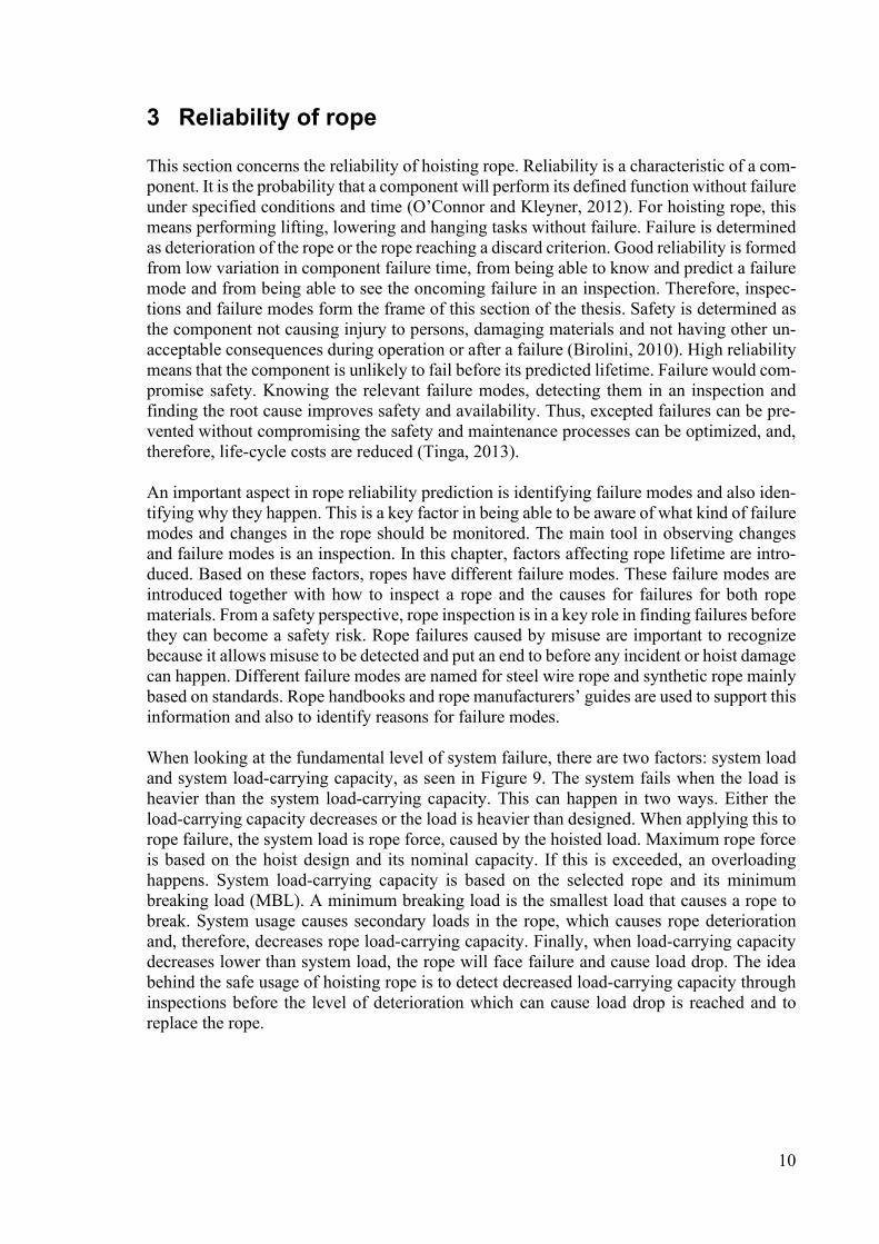
The system level failure that is considered as a hoisting rope failure is divided into two cat-egories: exceeding MBL and decreased MBL, as seen in Figure 10. This thesis focuses on decreased MBL. Factors causing decreased rope MBL are rope fatigue, mechanical dam-ages, wear and environmental stresses. All the failure causes introduced in section 3.2 can be categorized into these groups. In the following section, factors affecting rope lifetime are introduced. These factors affect the rate of deterioration. For example, rope bending causes bending fatigue and eventually broken wires. The tightness of the bend affects the rate of bending fatigue deterioration.
Figure 10. Rope failure causes
12
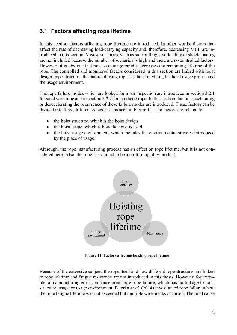
3.1 Factors affecting rope lifetime In this section, factors affecting rope lifetime are introduced. In other words, factors that affect the rate of decreasing load-carrying capacity and, therefore, decreasing MBL are in-troduced in this section. Misuse scenarios, such as side pulling, overloading or shock loading are not included because the number of scenarios is high and there are no controlled factors. However, it is obvious that misuse damage rapidly decreases the remaining lifetime of the rope. The controlled and monitored factors considered in this section are linked with hoist design, rope structure, the nature of using rope as a hoist medium, the hoist usage profile and the usage environment. The rope failure modes which are looked for in an inspection are introduced in section 3.2.1 for steel wire rope and in section 3.2.2 for synthetic rope. In this section, factors accelerating or deaccelerating the occurrence of these failure modes are introduced. These factors can be divided into three different categories, as seen in Figure 11. The factors are related to:
the hoist structure, which is the hoist design the hoist usage, which is how the hoist is used the hoist usage environment, which includes the environmental stresses introduced
by the place of usage.
Although, the rope manufacturing process has an effect on rope lifetime, but it is not con-sidered here. Also, the rope is assumed to be a uniform quality product.
Figure 11. Factors affecting hoisting rope lifetime
Because of the extensive subject, the rope itself and how different rope structures are linked to rope lifetime and fatigue resistance are not introduced in this thesis. However, for exam-ple, a manufacturing error can cause premature rope failure, which has no linkage to hoist structure, usage or usage environment. Peterka et al. (2014) investigated rope failure where the rope fatigue lifetime was not exceeded but multiple wire breaks occurred. The final cause
13
of the wire breakage was the manufacturing of the rope, where some of the rope layers were manufactured from lower rope grade wires. This accelerated the rate of damage caused to the rope, the rate of wire breakage and deformed the rope where strand layers came in contact with each other (Peterka et al., 2014).
3.1.1 Hoist structure
Hoist structure is relevant when considering rope lifetime. The rope is in contact with a hoist through the drum and sheaves. The rope is also secured to the drum at one end and fixed to the hoist or another drum at the other. This section concerns the drum and sheaves, which affect rope lifetime. The drum and the sheaves are known to have a relation with rope life-time according to crane design standards and the target company’s empirical knowledge. Relevant features on the drum are the fleet angle, the drum groove shape and drum material. The fleet angle is the angle between the drum grooves and the rope which is in contact with the drum. The fleet angle also exists between the rope and the sheave, where the same rules apply. This angle should be less than 4 degrees for non-rotation resistant ropes and less than 2 degrees for rotation resistant ropes (Finnish Standards Association, 2013). A larger fleet can lead to accelerated rope deterioration (Wire Rope Technical Board, 2005). The drum groove shape is also defined in the EN 13135 standard. The correct shape supports the rope. However, during operation, the grooves become worn and the groove crowns become sharper. The sharp groove crowns accelerate rope deterioration with both steel wire and syn-thetic ropes. The drum surface is also one possible source of rope wear. If the surface of the drum is rough or abrasive, it accelerates external wear especially with synthetic ropes. De-pending on the hoist design, another typical feature is the rope guide. The rope guide travels on the drum surface and ensures that the rope stays in the right drum groove. Unsuitable design or failure of the rope guide can damage the rope or the drum grooves and, therefore, accelerate deterioration. The rope is also influenced by the sheaves. The number of sheaves can vary from zero to dozens, and the number of bends in the rope when it goes through the sheaves naturally affects rope fatigue lifetime. The sheaves have two main factors that affect rope lifetime. The D/d-ratio is the ratio between the sheave diameter and the rope nominal diameter. Crane design standards define the minimum D/d-ratio for the rope. Increasing the ratio gives the rope greater fatigue lifetime because the rope is not bent through so tight turns. Too small a D/d-ratio will accelerate bending fatigue (Wire Rope Technical Board, 2005). This can also be seen in the bending over sheave test, where smaller sheaves caused shorter rope life time (Onur, İmrak and Onur, 2019). The second factor is the sheave groove. A correctly dimen-sioned groove supports the rope by ensuring the rope shape as it cannot be too tight or rub against the sheave edges. Too tight a groove can also cause a hazardous twist in the rope (Finnish Standards Association, 2013).
3.1.2 Hoist usage
The nominal load is not the only criterion when selecting a suitable hoist. Hoist duty class determines the performance of the hoist. The classification defines the load spectrum, the designed number of working cycles, average vertical load movement and horizontal load movement (Finnish Standards Association, 2019b). From the point of view of the rope, the load spectrum is an important factor. It defines the ratio between light and heavy load cycles.
14
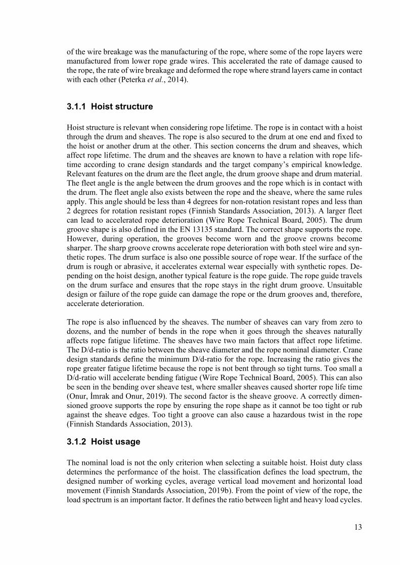
The same lifting cycle with the hoist nominal load and, for example, 50% of the nominal load have a different effect on the rope. Rope lifetime is substantially longer when the hoist is in light use and large loads are lifted infrequently. In other words, high rope forces cause high tensile stress to the rope, and, together with the lifting cycle, bending over the sheaves causes a shorter rope lifetime to be encountered (Onur, İmrak and Onur, 2019). Each rope type has its working load limit (WLL), which is the rope minimum breaking strength divided by the design factor (McKenna, Hearle and O’Hear, 2004). The design fac-tor, also known as the safety factor, depends on the application. In hoisting applications, the rope force must be less than the rope working load limit. The rope force is based on the lifted load, the weight of the hook block and the reeving. When a hoist and, therefore, a rope is maintained properly and when environmental stress has not influenced either and misuse has not occurred, a rope will face the end of its lifetime through fatigue failure. The fatigue is caused by bending, loading and unloading. Changes in hoisting speed also cause dynamic stress to the rope. When the rope is bent around a sheave or a drum, the rope strands and wires can only move in the form of the rope and the tension in each wire changes. This causes fatigue damage in steel wires, which leads to bro-ken wires (Wire Rope Technical Board, 2005). The wires and strands moving can also cause internal wear. Especially with synthetic ropes, the internal abrasion is caused by bending and the strands moving against each other. This phenomenon is also considered as the internal wear of synthetic rope (McKenna, Hearle and O’Hear, 2004). Different parts of the rope see a different amount of bends. In Figure 12, the rope is consid-ered lowered in the topmost row and hoisted up in the bottom row. The rope travels through the sheaves and ends up on the drum. The area that sees the most bends is marked with the red box. If the bend on the drum goes in the opposite direction than the bend on the first sheave, it is called reverse bending. This reverse bending is seen in Figure 1 between the drum and the first sheave and in Figure 14 between numbers 1 and 2. Reverse bending causes greater rope deterioration than normal bending (Wire Rope Technology Aachen, 2018). The level of greater deterioration depends on the distance between the opposite direction bends. A shorter distance means even greater damage (Wire Rope Technology Aachen, 2018). Therefore, if the full length of the rope is used in lifting and the reeving includes reverse bending, the rope comes under a great amount of bending fatigue damage. The red box in Figure 12 marks the locations of the greatest damages.
Figure 12. Rope bends through the sheaves, adapted from Wire Rope Technology Aachen (2018)

15
3.1.3 Usage environment
The hoist usage environment has a role in rope lifetime. Depending on the environment, there could be fluctuating temperatures, increased humidity or grit particles in the air. The usage environment may compromise the rope with corrosion, chemical contamination or UV-radiation. Typically, rope temperature has a significant role. Also, a marine environment is a typical usage environment for a hoist, which can accelerate the corrosion of the rope. Failure modes and causes related to environmental factors are introduced in section 3.2. Rope temperature may increase through internal heat production or based on ambient tem-perature. Bending a rope causes friction between the rope strands, wires and filaments. Fric-tion forms heat. If the rope speed is high and the hoist is in operation constantly, the temper-ature of the rope may increase. In steel wire rope, increased temperature can cause the rope grease to become fluid and lower its lubrication properties. This accelerates internal friction and, therefore, internal abrasion (Finnish Standards Association, 2012b). For UHMWPE rope, its low melting point, 150 degrees Celsius (Finnish Standards Association, 2019a), makes it vulnerable to increased temperatures. UHMWPE as a material has low conductivity of heat, which increases its vulnerability to high temperatures. Polymer sheaves are also less heat conductive than steel sheaves. Increased temperature accelerates rope deterioration. Be-low the melting temperature, temperature itself is not a problem, but it affects other factors and reduces filaments strength and increases filament creep (McKenna, Hearle and O’Hear, 2004). High ambient temperature is another source of rope temperature increase. It affects rope lifetime similarly to other temperature issues.
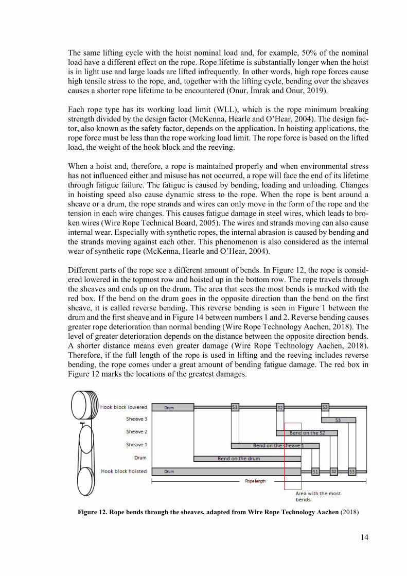
3.2 Inspection To be able to control the reliability of rope, regular inspections of the rope are in a key role. Through the inspections, rope condition is monitored by a competent person. Rope inspec-tion is typically performed as part of larger hoist and crane inspections. Rope inspection is not only about inspecting the rope itself but it is also tied with inspecting components that function with the rope, which are introduced in Figure 13. Rope inspection sections. With the inspections, development of deterioration, such as wear, is noticed at an early stage. The development is monitored through inspecting the rope at certain time intervals, and the rope is discarded when the deterioration reaches a discard limit. Therefore, rope lifetime is con-trolled and safe usage is secured. In everyday life, an operator should visually inspect the rope before starting work with the crane. The operator should be looking for signs of deteri-oration or mechanical damage. The correct spooling on the drum and the sheaves should also be inspected (Finnish Standards Association, 2012b). The operator’s daily inspection plays an important role in spotting failures caused by misuse as these failures occur immediately after misuse and can cause high-risk situations. However, the operator’s daily visual inspec-tion is typically a very limited inspection and, therefore, a professional is required to perform a more thorough analysis. In the following subsections, the failure types of steel wire rope and synthetic rope are introduced.
16
Figure 13. Rope inspection sections
3.2.1 Steel wire rope
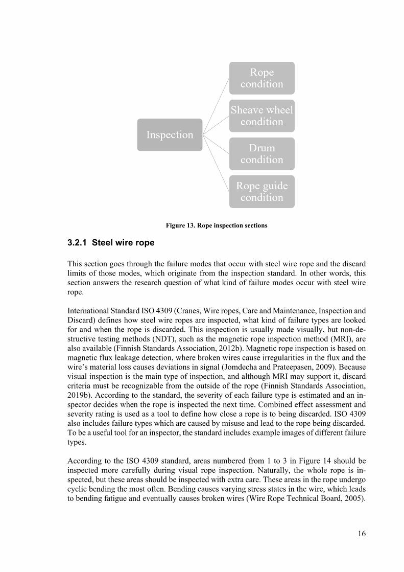
This section goes through the failure modes that occur with steel wire rope and the discard limits of those modes, which originate from the inspection standard. In other words, this section answers the research question of what kind of failure modes occur with steel wire rope. International Standard ISO 4309 (Cranes, Wire ropes, Care and Maintenance, Inspection and Discard) defines how steel wire ropes are inspected, what kind of failure types are looked for and when the rope is discarded. This inspection is usually made visually, but non-de-structive testing methods (NDT), such as the magnetic rope inspection method (MRI), are also available (Finnish Standards Association, 2012b). Magnetic rope inspection is based on magnetic flux leakage detection, where broken wires cause irregularities in the flux and the wire’s material loss causes deviations in signal (Jomdecha and Prateepasen, 2009). Because visual inspection is the main type of inspection, and although MRI may support it, discard criteria must be recognizable from the outside of the rope (Finnish Standards Association, 2019b). According to the standard, the severity of each failure type is estimated and an in-spector decides when the rope is inspected the next time. Combined effect assessment and severity rating is used as a tool to define how close a rope is to being discarded. ISO 4309 also includes failure types which are caused by misuse and lead to the rope being discarded. To be a useful tool for an inspector, the standard includes example images of different failure types. According to the ISO 4309 standard, areas numbered from 1 to 3 in Figure 14 should be inspected more carefully during visual rope inspection. Naturally, the whole rope is in-spected, but these areas should be inspected with extra care. These areas in the rope undergo cyclic bending the most often. Bending causes varying stress states in the wire, which leads to bending fatigue and eventually causes broken wires (Wire Rope Technical Board, 2005).

17
Bending also causes friction and wear in the wires and strands by making them rub against each other.
Figure 14. Rope key areas for closer inspection (Finnish Standards Association, 2012b)
Steel wire rope failure modes are categorized into four different groups in this thesis. These categories are broken wires, decrease in rope diameter, corrosion and rope deformation (Finnish Standards Association, 2012b). A rope may suffer from more than one deterioration type. To be able to evaluate the rope’s remaining lifetime and inspection interval, an inspector can use the combined effect assess-ment and severity rating introduced in ISO 4309. In combined effect assessment, various types of deterioration are examined, especially when they occur in the same area and the overall assessment is performed for combined rope health. All explored steel wire rope fail-ure modes are listed in Figure 15, where the third level is the failure modes and the fourth level is the failure causes. In the following, broken wires and decreased rope diameter are used as an example. If the amount of broken wires in the inspected rope adds up to 50% of the discard limit and the rope diameter has also decreased to 50% of the diameter of a new rope, the combined effect assessment brings the total to 100%, meaning the rope needs to be discarded. However, if both deterioration types are only 40% of their respective areas, the total only comes to 80%, which means that the rope is approaching the end of its lifetime and needs to be frequently inspected. (Finnish Standards Association, 2012) An important starting point for any inspection is a log of previous inspections and the rec-orded type and severity of the findings. The location of found damages should also be noted down to make sure that those damages can be found again and their development can be evaluated. Rope identification data, such as installation date, type, material and usage profile

18
must also be available for the inspector. All this data must match the hoist in question. If the log is not available or if the rope does not match the hoist, the rope shall be discarded.
Figure 15. Steel wire rope failure causes
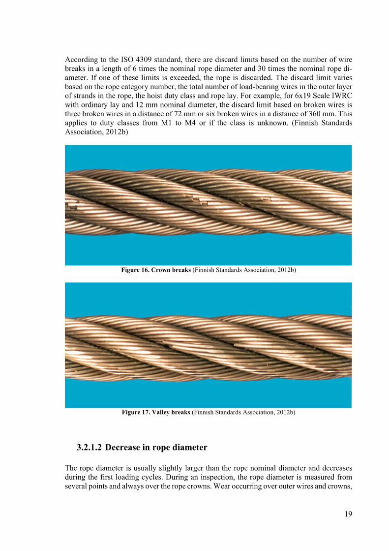
3.2.1.1 Broken wires The primary rope degradation type in hoisting applications are broken wires and decrease in rope diameter. Broken wires are categorized into crown breaks, as seen in Figure 16, and valley breaks, as seen in Figure 17. Crown breaks occur on the top of the strand, as the word crown indicates. Crown breaks are a sign of normal wear and typically have square or Z-shaped ends, signalling fatigue breaks. Valley breaks are a sign of abnormal degradation caused, for example, by the loss of core support, small sheave grooves or unusually high rope loading. Valley breaks are more difficult to detect, especially on dirty ropes. Because valley breaks are more difficult to detect and a sign of abnormal degradation, they are a safety risk and also indicate usage conditions that are causing faster internal degradation than outer degradation (Wire Rope Technical Board, 2005).
19
According to the ISO 4309 standard, there are discard limits based on the number of wire breaks in a length of 6 times the nominal rope diameter and 30 times the nominal rope di-ameter. If one of these limits is exceeded, the rope is discarded. The discard limit varies based on the rope category number, the total number of load-bearing wires in the outer layer of strands in the rope, the hoist duty class and rope lay. For example, for 6x19 Seale IWRC with ordinary lay and 12 mm nominal diameter, the discard limit based on broken wires is three broken wires in a distance of 72 mm or six broken wires in a distance of 360 mm. This applies to duty classes from M1 to M4 or if the class is unknown. (Finnish Standards Association, 2012b)
Figure 16. Crown breaks (Finnish Standards Association, 2012b)
Figure 17. Valley breaks (Finnish Standards Association, 2012b)
3.2.1.2 Decrease in rope diameter The rope diameter is usually slightly larger than the rope nominal diameter and decreases during the first loading cycles. During an inspection, the rope diameter is measured from several points and always over the rope crowns. Wear occurring over outer wires and crowns,

20
as seen in Figure 18, is normal deterioration for the rope. However, accelerated external wear can be caused by wear on rope sheaves with improper shape or rope imprints. Also, wear and a sharp crest shape on a drum can cause accelerated external wear to the rope. External wear on wires is rather easy to monitor by visual inspection because the round outer surface of wires turns flat. By measuring the rope diameter using callipers, internal wear is measured together with external wear. Without measurement, internal wear between wires is not pos-sible to monitor and causes risks to the safety of the operation. Improper lubrication causes increased internal friction in the rope and leads to internal wear. According to the ISO 4309 standard, uniform decrease in rope nominal diameter for discard is 10% for single-layer with fibre core ropes, 7,5% for single-layer with steel core or parallel-closed ropes and 5% for rotation-resistant ropes (Finnish Standards Association, 2012b).
Figure 18. External wear on rope strands (Finnish Standards Association, 2012b)
3.2.1.3 Corrosion Steel wire ropes can be manufactured as galvanized to protect them from corrosion (Wire Rope Technical Board, 2005). However, that does not stop corrosion from happening. In a galvanized rope, the corrosion rate is lower. Before inspecting the rope for corrosion, the rope surface should be wiped clean to distinguish corrosion of the wires and corrosion by foreign particles. According to the ISO 4309 standard, wire rope corrosion is divided into three categories: external, internal and fretting corrosion. In external corrosion, as seen in Figure 19, if surface oxidation can be wiped clean, it is not considered deterioration. Corro-sion caused by a rough surface is considered deterioration, and when wires are heavily pitted and become slack, the rope should be discarded. Internal corrosion occurs inside the rope between the wires. This type of corrosion is dangerous because it is difficult to detect. A visible sign of internal corrosion is finding corrosion in strand and wire valleys. If a sign of internal corrosion is detected, the rope shall be discarded, or a precise internal examination is performed for further analysis and decision-making. Fretting corrosion is where wires rub against each other and then oxidise. It causes material losses, and a typical sign of fretting corrosion is red rust powder. (Finnish Standards Association, 2012b)
21
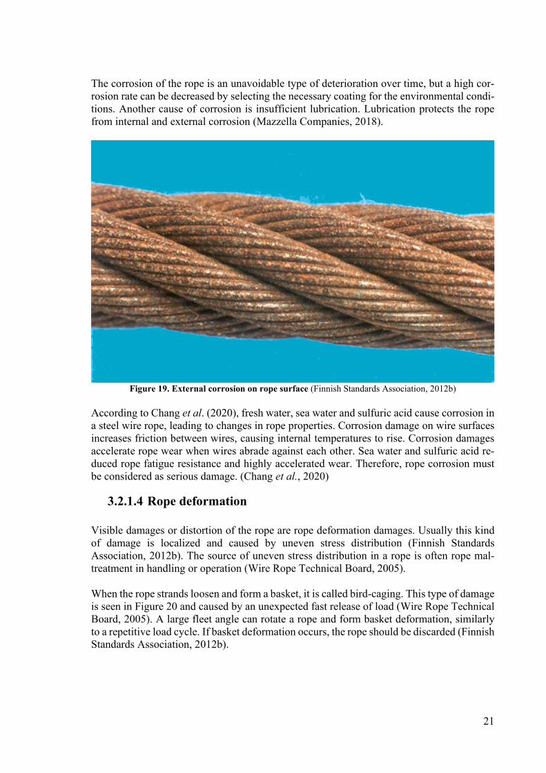
The corrosion of the rope is an unavoidable type of deterioration over time, but a high cor-rosion rate can be decreased by selecting the necessary coating for the environmental condi-tions. Another cause of corrosion is insufficient lubrication. Lubrication protects the rope from internal and external corrosion (Mazzella Companies, 2018).
Figure 19. External corrosion on rope surface (Finnish Standards Association, 2012b)
According to Chang et al. (2020), fresh water, sea water and sulfuric acid cause corrosion in a steel wire rope, leading to changes in rope properties. Corrosion damage on wire surfaces increases friction between wires, causing internal temperatures to rise. Corrosion damages accelerate rope wear when wires abrade against each other. Sea water and sulfuric acid re-duced rope fatigue resistance and highly accelerated wear. Therefore, rope corrosion must be considered as serious damage. (Chang et al., 2020)
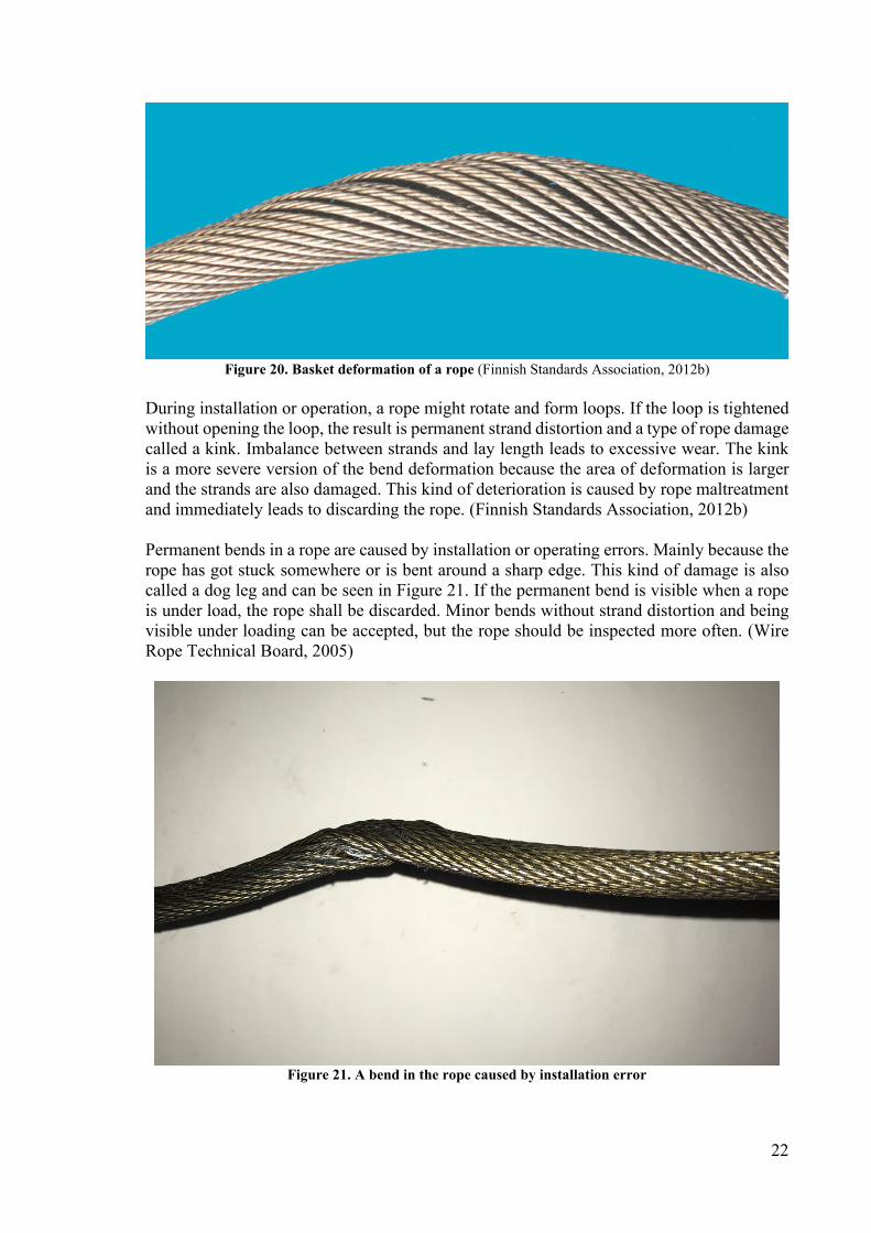
3.2.1.4 Rope deformation Visible damages or distortion of the rope are rope deformation damages. Usually this kind of damage is localized and caused by uneven stress distribution (Finnish Standards Association, 2012b). The source of uneven stress distribution in a rope is often rope mal-treatment in handling or operation (Wire Rope Technical Board, 2005). When the rope strands loosen and form a basket, it is called bird-caging. This type of damage is seen in Figure 20 and caused by an unexpected fast release of load (Wire Rope Technical Board, 2005). A large fleet angle can rotate a rope and form basket deformation, similarly to a repetitive load cycle. If basket deformation occurs, the rope should be discarded (Finnish Standards Association, 2012b).
22
Figure 20. Basket deformation of a rope (Finnish Standards Association, 2012b)
During installation or operation, a rope might rotate and form loops. If the loop is tightened without opening the loop, the result is permanent strand distortion and a type of rope damage called a kink. Imbalance between strands and lay length leads to excessive wear. The kink is a more severe version of the bend deformation because the area of deformation is larger and the strands are also damaged. This kind of deterioration is caused by rope maltreatment and immediately leads to discarding the rope. (Finnish Standards Association, 2012b) Permanent bends in a rope are caused by installation or operating errors. Mainly because the rope has got stuck somewhere or is bent around a sharp edge. This kind of damage is also called a dog leg and can be seen in Figure 21. If the permanent bend is visible when a rope is under load, the rope shall be discarded. Minor bends without strand distortion and being visible under loading can be accepted, but the rope should be inspected more often. (Wire Rope Technical Board, 2005)
Figure 21. A bend in the rope caused by installation error
23
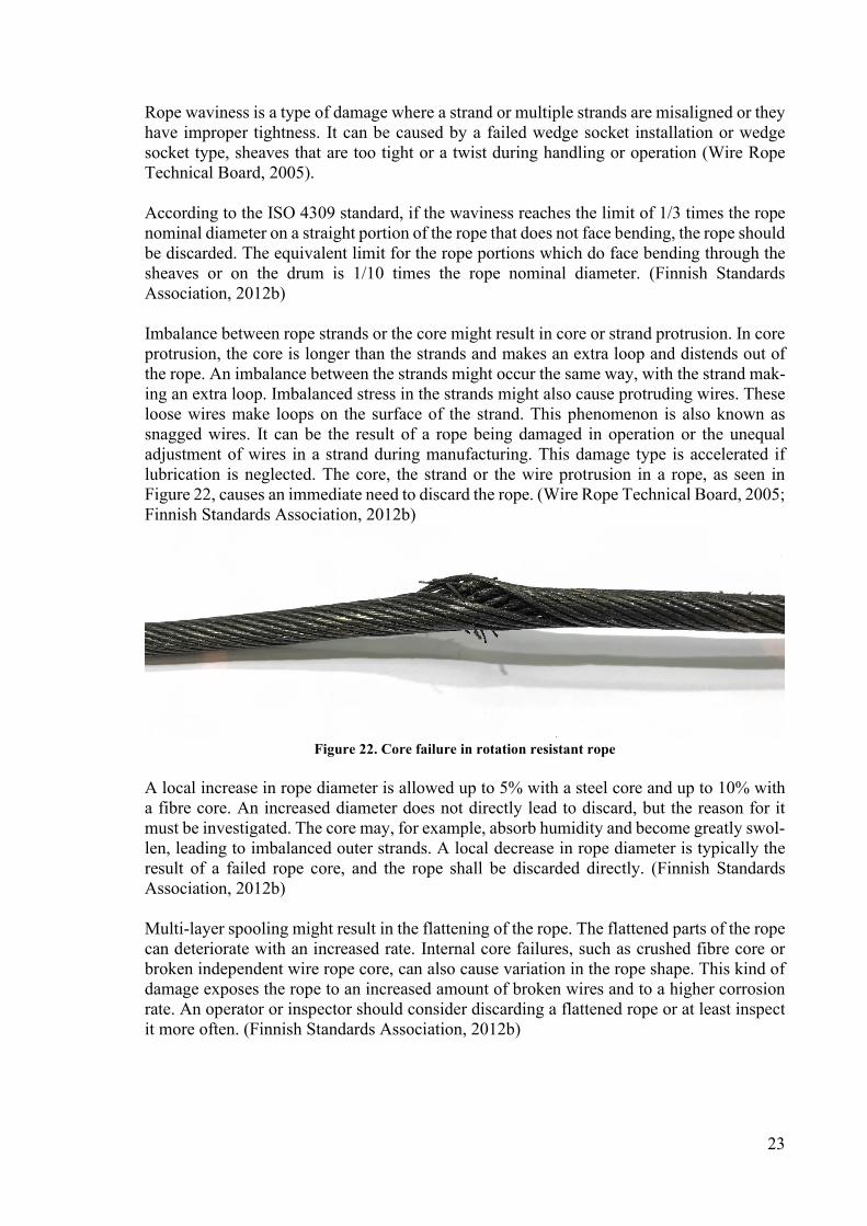
Rope waviness is a type of damage where a strand or multiple strands are misaligned or they have improper tightness. It can be caused by a failed wedge socket installation or wedge socket type, sheaves that are too tight or a twist during handling or operation (Wire Rope Technical Board, 2005). According to the ISO 4309 standard, if the waviness reaches the limit of 1/3 times the rope nominal diameter on a straight portion of the rope that does not face bending, the rope should be discarded. The equivalent limit for the rope portions which do face bending through the sheaves or on the drum is 1/10 times the rope nominal diameter. (Finnish Standards Association, 2012b) Imbalance between rope strands or the core might result in core or strand protrusion. In core protrusion, the core is longer than the strands and makes an extra loop and distends out of the rope. An imbalance between the strands might occur the same way, with the strand mak-ing an extra loop. Imbalanced stress in the strands might also cause protruding wires. These loose wires make loops on the surface of the strand. This phenomenon is also known as snagged wires. It can be the result of a rope being damaged in operation or the unequal adjustment of wires in a strand during manufacturing. This damage type is accelerated if lubrication is neglected. The core, the strand or the wire protrusion in a rope, as seen in Figure 22, causes an immediate need to discard the rope. (Wire Rope Technical Board, 2005; Finnish Standards Association, 2012b)
Figure 22. Core failure in rotation resistant rope
A local increase in rope diameter is allowed up to 5% with a steel core and up to 10% with a fibre core. An increased diameter does not directly lead to discard, but the reason for it must be investigated. The core may, for example, absorb humidity and become greatly swol-len, leading to imbalanced outer strands. A local decrease in rope diameter is typically the result of a failed rope core, and the rope shall be discarded directly. (Finnish Standards Association, 2012b) Multi-layer spooling might result in the flattening of the rope. The flattened parts of the rope can deteriorate with an increased rate. Internal core failures, such as crushed fibre core or broken independent wire rope core, can also cause variation in the rope shape. This kind of damage exposes the rope to an increased amount of broken wires and to a higher corrosion rate. An operator or inspector should consider discarding a flattened rope or at least inspect it more often. (Finnish Standards Association, 2012b)

24
If a rope is subjected to excessive heat and it changes colour or loses lubrication grease, the rope shall be discarded. Excessive heat might be the result of an electric arc or an improper grounding lead. (Finnish Standards Association, 2012b)
3.2.2 Synthetic rope
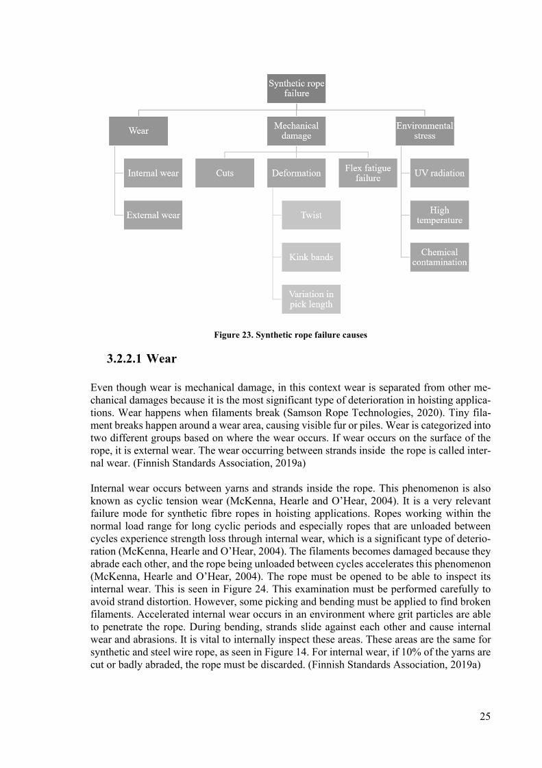
This section is about the failure modes that occur with synthetic hoisting rope and what are the discard limits for these failure modes. Hence, this section answers the research question of what kind of failure modes occur with synthetic rope. The inspection of a synthetic rope is made visually in the same way as with a steel wire rope. The inspector looks for filament breaks and deformation as signs of failure. Synthetic rope does not require lubrication; therefore, the rope is not covered by rope grease, making the inspection is cleaner and easier. Synthetic rope inspection and retirement is guided by the ISO 9554 Fibre ropes general specifications standard. The standard defines how a fibre rope is inspected and what kind of damages can be expected. In this thesis, deterioration types are categorized into the three following groups: wear, mechanical damage and environmental damage. Figure 23 lists the failure modes explored in this section. During the inspection, the rope’s full length is examined, and special attention is paid to the areas which face bending or which are used to form eye loops or long splices. An important tool for the inspector is the log of previous inspections and the recorded type and severity of findings. The location of found damages should be noted down to ensure that the inspector can pinpoint the same damages again. Rope identification data, such as the installation date, type, material and usage profile, should be available together with the in-spection log. All of this data must be accessible and match the hoist in question. Otherwise, the rope shall be discarded. If investigation is possible, unusual events, such as overloading, shock loading and chemical exposure, should be considered. Repeated overloading causes filament breaks and visible fur mostly inside the rope, which is similar to how cyclic fatigue damage affects synthetic ropes. On the other hand, shock loading can leave visible marks of the internal melting of the filaments especially on the rope end connection areas. Depending on the hoist construction, these rope end connection areas may not experience shock loading, and, therefore, the damage may not leave visible marks. (McKenna, Hearle and O’Hear, 2004) When comparing synthetic fibre rope inspection to steel wire rope inspection, the synthetic fibre rope has an advantage. Synthetic rope deterioration types cause broken filaments, which are visible as fur or a pile. Therefore, recognition of these deterioration signs is straightforward. The final rope condition estimation guide rule is defined in the following way in Handbook of fibre rope technology (McKenna, Hearle and O’Hear, 2004): “If it looks bad, it is bad”.
25
Figure 23. Synthetic rope failure causes
3.2.2.1 Wear Even though wear is mechanical damage, in this context wear is separated from other me-chanical damages because it is the most significant type of deterioration in hoisting applica-tions. Wear happens when filaments break (Samson Rope Technologies, 2020). Tiny fila-ment breaks happen around a wear area, causing visible fur or piles. Wear is categorized into two different groups based on where the wear occurs. If wear occurs on the surface of the rope, it is external wear. The wear occurring between strands inside the rope is called inter-nal wear. (Finnish Standards Association, 2019a) Internal wear occurs between yarns and strands inside the rope. This phenomenon is also known as cyclic tension wear (McKenna, Hearle and O’Hear, 2004). It is a very relevant failure mode for synthetic fibre ropes in hoisting applications. Ropes working within the normal load range for long cyclic periods and especially ropes that are unloaded between cycles experience strength loss through internal wear, which is a significant type of deterio-ration (McKenna, Hearle and O’Hear, 2004). The filaments becomes damaged because they abrade each other, and the rope being unloaded between cycles accelerates this phenomenon (McKenna, Hearle and O’Hear, 2004). The rope must be opened to be able to inspect its internal wear. This is seen in Figure 24. This examination must be performed carefully to avoid strand distortion. However, some picking and bending must be applied to find broken filaments. Accelerated internal wear occurs in an environment where grit particles are able to penetrate the rope. During bending, strands slide against each other and cause internal wear and abrasions. It is vital to internally inspect these areas. These areas are the same for synthetic and steel wire rope, as seen in Figure 14. For internal wear, if 10% of the yarns are cut or badly abraded, the rope must be discarded. (Finnish Standards Association, 2019a)

26
Figure 24. An opened rope with internal wear between strands
According to Handbook of fibre rope technology, the rope circumference should also be monitored at several points in the rope, especially at damage areas, and compared to other measured values of the rope in question. The measurements should only vary up to 10% in any area of the rope. Otherwise, the rope shall be discarded. However, note that rope diam-eters measured on ropes in service are often smaller than on brand new ropes. That is caused by the rope settling and stretching during the first cycles. Rope wear also decreases rope diameter. (McKenna, Hearle and O’Hear, 2004) External wear or external abrasions are a normal localised phenomenon in areas that drag over surfaces, and it does not cause any significant weakening of the rope. In hoisting appli-cations, these surfaces areas are where the rope is bent over the drum and sheaves. In a hollow single-braid rope structure, the external wear occurs especially on the crowns of the strands, as seen in Figure 25 (McKenna, Hearle and O’Hear, 2004). Together with abrasions caused by fixed objects, a uniform abrasion can be caused by dragging over rough surfaces. This phenomenon is seen in Figure 26, and it is caused by abrasions or cyclic tension wear (Samson Rope Technologies, 2020). If a sharp or rough surface causes heavy external wear and even partially broken strands, as seen in Figure 26, discarding should be considered. External wear might also occur on the inside of an eye splice. ISO 9554 also defines discard criteria. According to the standard, if 50% of the outer yarn is abraded or cut in the crown area, the rope shall be discarded. (Finnish Standards Association, 2019a)
Figure 25. External wear and small filament cuts
27
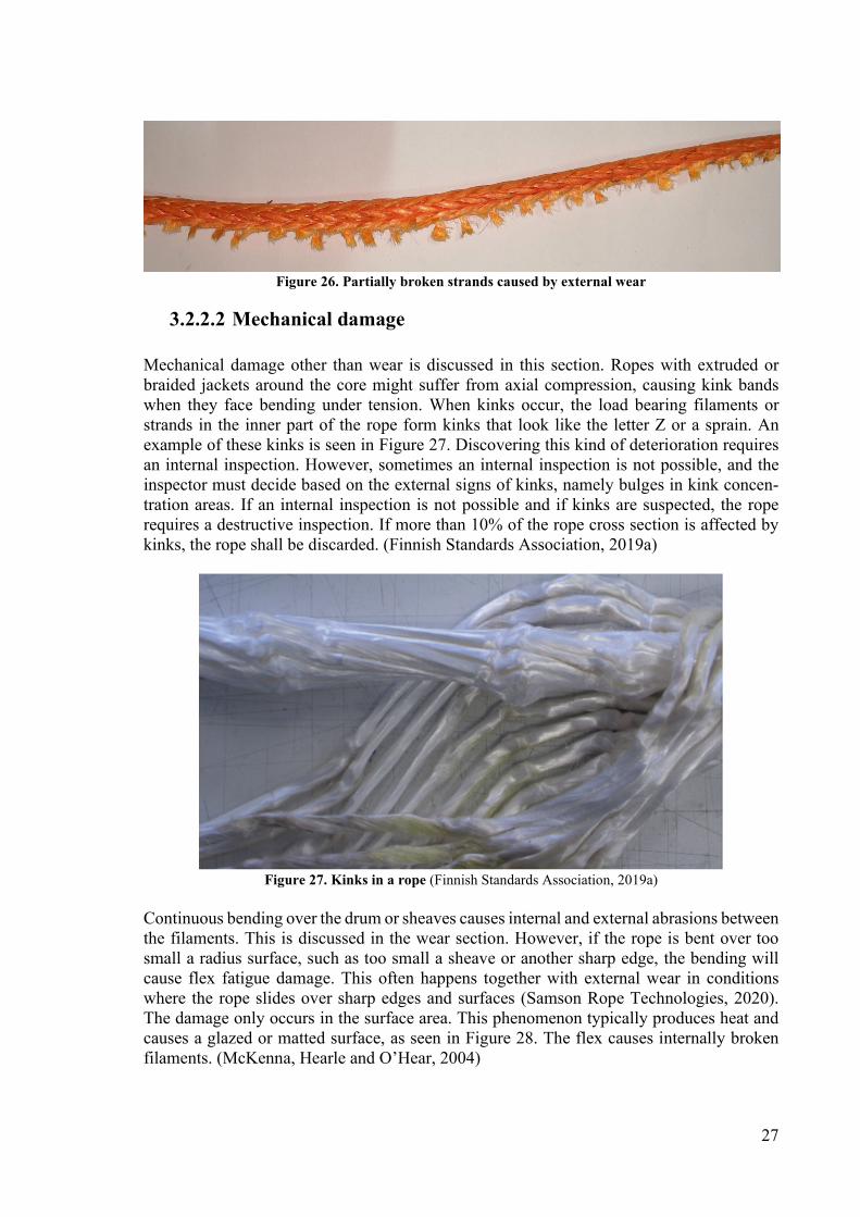
Figure 26. Partially broken strands caused by external wear
3.2.2.2 Mechanical damage Mechanical damage other than wear is discussed in this section. Ropes with extruded or braided jackets around the core might suffer from axial compression, causing kink bands when they face bending under tension. When kinks occur, the load bearing filaments or strands in the inner part of the rope form kinks that look like the letter Z or a sprain. An example of these kinks is seen in Figure 27. Discovering this kind of deterioration requires an internal inspection. However, sometimes an internal inspection is not possible, and the inspector must decide based on the external signs of kinks, namely bulges in kink concen-tration areas. If an internal inspection is not possible and if kinks are suspected, the rope requires a destructive inspection. If more than 10% of the rope cross section is affected by kinks, the rope shall be discarded. (Finnish Standards Association, 2019a)
Figure 27. Kinks in a rope (Finnish Standards Association, 2019a)
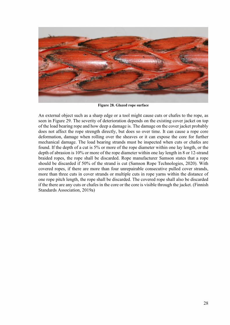
Continuous bending over the drum or sheaves causes internal and external abrasions between the filaments. This is discussed in the wear section. However, if the rope is bent over too small a radius surface, such as too small a sheave or another sharp edge, the bending will cause flex fatigue damage. This often happens together with external wear in conditions where the rope slides over sharp edges and surfaces (Samson Rope Technologies, 2020). The damage only occurs in the surface area. This phenomenon typically produces heat and causes a glazed or matted surface, as seen in Figure 28. The flex causes internally broken filaments. (McKenna, Hearle and O’Hear, 2004)
28
Figure 28. Glazed rope surface
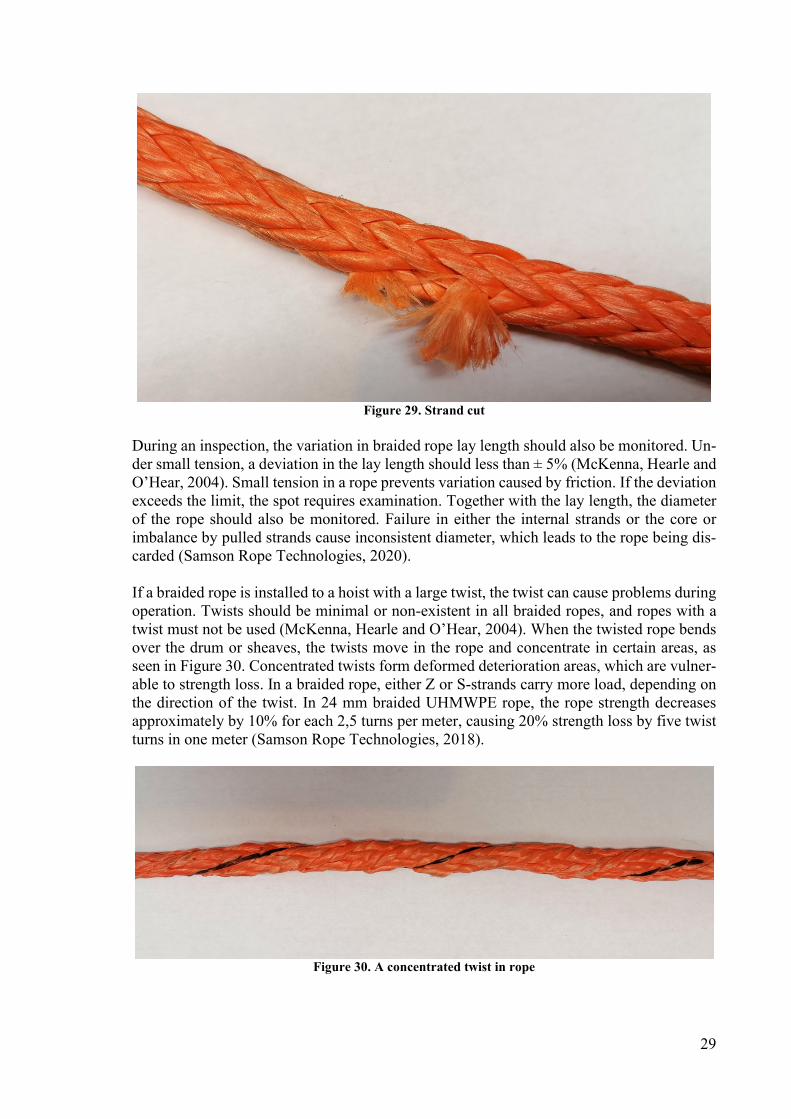
An external object such as a sharp edge or a tool might cause cuts or chafes to the rope, as seen in Figure 29. The severity of deterioration depends on the existing cover jacket on top of the load bearing rope and how deep a damage is. The damage on the cover jacket probably does not affect the rope strength directly, but does so over time. It can cause a rope core deformation, damage when rolling over the sheaves or it can expose the core for further mechanical damage. The load bearing strands must be inspected when cuts or chafes are found. If the depth of a cut is 5% or more of the rope diameter within one lay length, or the depth of abrasion is 10% or more of the rope diameter within one lay length in 8 or 12-strand braided ropes, the rope shall be discarded. Rope manufacturer Samson states that a rope should be discarded if 50% of the strand is cut (Samson Rope Technologies, 2020). With covered ropes, if there are more than four unrepairable consecutive pulled cover strands, more than three cuts in cover strands or multiple cuts in rope yarns within the distance of one rope pitch length, the rope shall be discarded. The covered rope shall also be discarded if the there are any cuts or chafes in the core or the core is visible through the jacket. (Finnish Standards Association, 2019a)
29
Figure 29. Strand cut
During an inspection, the variation in braided rope lay length should also be monitored. Un-der small tension, a deviation in the lay length should less than ± 5% (McKenna, Hearle and O’Hear, 2004). Small tension in a rope prevents variation caused by friction. If the deviation exceeds the limit, the spot requires examination. Together with the lay length, the diameter of the rope should also be monitored. Failure in either the internal strands or the core or imbalance by pulled strands cause inconsistent diameter, which leads to the rope being dis-carded (Samson Rope Technologies, 2020). If a braided rope is installed to a hoist with a large twist, the twist can cause problems during operation. Twists should be minimal or non-existent in all braided ropes, and ropes with a twist must not be used (McKenna, Hearle and O’Hear, 2004). When the twisted rope bends over the drum or sheaves, the twists move in the rope and concentrate in certain areas, as seen in Figure 30. Concentrated twists form deformed deterioration areas, which are vulner-able to strength loss. In a braided rope, either Z or S-strands carry more load, depending on the direction of the twist. In 24 mm braided UHMWPE rope, the rope strength decreases approximately by 10% for each 2,5 turns per meter, causing 20% strength loss by five twist turns in one meter (Samson Rope Technologies, 2018).
Figure 30. A concentrated twist in rope

30
3.2.2.3 Environmental damage During operation, installation or transportation, a rope might suffer environmental stress and deteriorate. How strongly an environmental factor affects the rope lifetime depends on the synthetic rope material. For example, according to the ISO 9554 standard, the discard limit for short-term exposure of high temperatures for UHMWPE ropes is over 70 degrees Celsius and for Aramid fibres the same limit is 300 degrees Celsius (Finnish Standards Association, 2019a). Samson states that an UHMWPE rope’s recommended maximum operating temper-ature is 60 degrees Celsius, and in that temperature, the rope strength is reduced by 6% (Samson Rope Technologies, 2016b). However, ropes stored in a temperature of 75 degrees Celsius and tested at room temperature did not suffer from strength reduction (Samson Rope Technologies, 2016b). A source of thermal damage can be internal friction, friction from sliding over surfaces, ambient temperature or temperature exposure to a heat source such as welding or grinding. If the rope has flattened thermal damage areas with marks of melting and hardening, the rope shall be discarded. Also, if 20% or a larger percentage of yarn is affected by melting or fusing, the rope shall be discarded. (Finnish Standards Association, 2019a) UV radiation can also cause defects in a rope. The outer rope yarns are susceptible to em-brittlement and becoming weaker. Typical marks of deterioration are colour changes and, on a more severe level, broken filaments. Exposing a UHMWPE rope to high intensity UV radiation for one year reduced the rope strength by 10% as compared to a new rope (Samson Rope Technologies, 2016a). The direct numerical limit of UV degradation is not defined in ISO 9554, but on a more general level, if the rope suffers from UV degradation, the rope shall be discarded (Finnish Standards Association, 2019a). A synthetic rope’s resistance to chemicals varies based on the rope material. If the rope is exposed to a chemical which is not anticipated in the rope selection, the basic principle is that the rope shall be discarded. However, the rope manufacturer should be consulted if the rope is resistant to the chemical in question. Oil or grease contamination is not considered a chemical contamination and can be washed or whipped away. If the rope is heavily contam-inated and the grease cannot be washed away, the rope is recommended to be discarded (McKenna, Hearle and O’Hear, 2004). (Finnish Standards Association, 2019a) UHMWPE fibre is polyethylene-based, and its chemical structure does not contain chemical groups such as aromatic rings that are vulnerable to aggressive chemical agents. This leads to a high resistance to chemicals, acids and alkali deterioration. The weakness of UHMWPE fibres is a strongly oxidizing environment, and the fibres lose their strength very fast (Bunsell, 2009). If any fused or brittle filaments are found during an inspection or if the rope has become stiff, the rope should be discarded (Samson Rope Technologies, 2020). If a synthetic rope has got damp or wet, it should be hung to dry. Wetting does not directly harm the rope but it can assist grit particles in penetrating the rope and cause internal wear. This should also be considered during transportation and storing. High humidity conditions might cause mildew growth on to the rope. However, synthetic fibres are not vulnerable to mildew and can be washed with water. (Finnish Standards Association, 2019a)
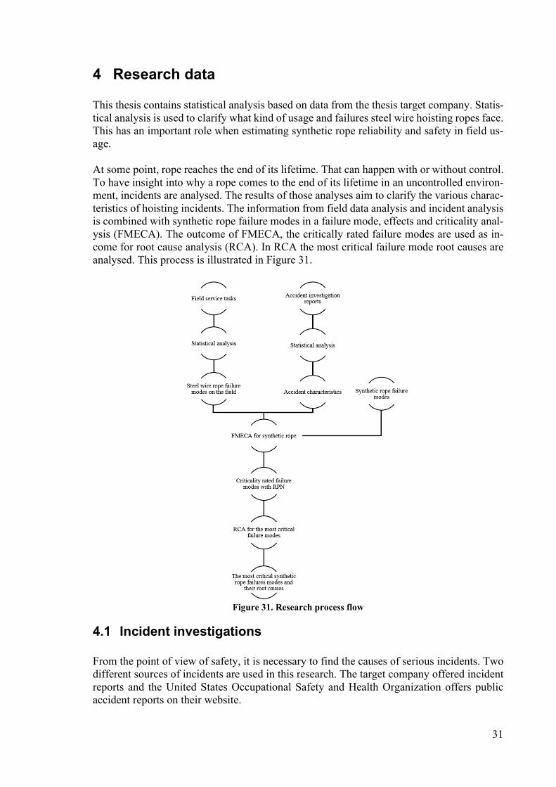
31
4 Research data This thesis contains statistical analysis based on data from the thesis target company. Statis-tical analysis is used to clarify what kind of usage and failures steel wire hoisting ropes face. This has an important role when estimating synthetic rope reliability and safety in field us-age. At some point, rope reaches the end of its lifetime. That can happen with or without control. To have insight into why a rope comes to the end of its lifetime in an uncontrolled environ-ment, incidents are analysed. The results of those analyses aim to clarify the various charac-teristics of hoisting incidents. The information from field data analysis and incident analysis is combined with synthetic rope failure modes in a failure mode, effects and criticality anal-ysis (FMECA). The outcome of FMECA, the critically rated failure modes are used as in-come for root cause analysis (RCA). In RCA the most critical failure mode root causes are analysed. This process is illustrated in Figure 31.
Figure 31. Research process flow
4.1 Incident investigations From the point of view of safety, it is necessary to find the causes of serious incidents. Two different sources of incidents are used in this research. The target company offered incident reports and the United States Occupational Safety and Health Organization offers public accident reports on their website.
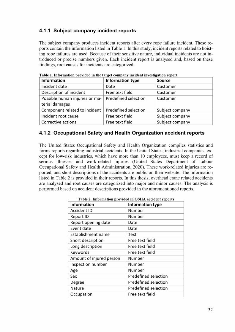
32
4.1.1 Subject company incident reports
The subject company produces incident reports after every rope failure incident. These re-ports contain the information listed in Table 1. In this study, incident reports related to hoist-ing rope failures are used. Because of their sensitive nature, individual incidents are not in-troduced or precise numbers given. Each incident report is analysed and, based on these findings, root causes for incidents are categorized. Table 1. Information provided in the target company incident investigation report
Information Information type Source
Incident date Date Customer
Description of incident Free text field Customer
Possible human injuries or ma-terial damages
Predefined selection Customer
Component related to incident Predefined selection Subject company
Incident root cause Free text field Subject company
Corrective actions Free text field Subject company
4.1.2 Occupational Safety and Health Organization accident reports
The United States Occupational Safety and Health Organization compiles statistics and forms reports regarding industrial accidents. In the United States, industrial companies, ex-cept for low-risk industries, which have more than 10 employees, must keep a record of serious illnesses and work-related injuries (United States Department of Labour Occupational Safety and Health Administration, 2020). These work-related injuries are re-ported, and short descriptions of the accidents are public on their website. The information listed in Table 2 is provided in their reports. In this thesis, overhead crane related accidents are analysed and root causes are categorized into major and minor causes. The analysis is performed based on accident descriptions provided in the aforementioned reports.
Table 2. Information provided in OSHA accident reports
Information Information type
Accident ID Number
Report ID Number
Report opening date Date
Event date Date
Establishment name Text
Short description Free text field
Long description Free text field
Keywords Free text field
Amount of injured person Number
Inspection number Number
Age Number
Sex Predefined selection
Degree Predefined selection
Nature Predefined selection
Occupation Free text field
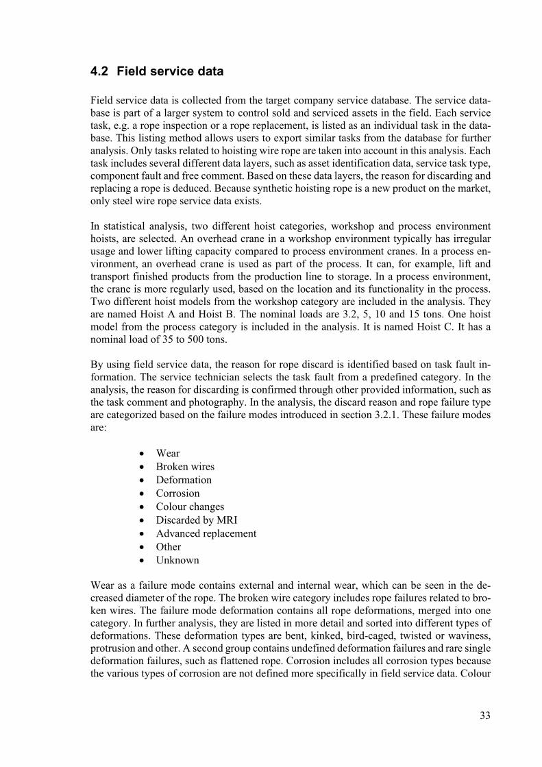
33
4.2 Field service data Field service data is collected from the target company service database. The service data-base is part of a larger system to control sold and serviced assets in the field. Each service task, e.g. a rope inspection or a rope replacement, is listed as an individual task in the data-base. This listing method allows users to export similar tasks from the database for further analysis. Only tasks related to hoisting wire rope are taken into account in this analysis. Each task includes several different data layers, such as asset identification data, service task type, component fault and free comment. Based on these data layers, the reason for discarding and replacing a rope is deduced. Because synthetic hoisting rope is a new product on the market, only steel wire rope service data exists. In statistical analysis, two different hoist categories, workshop and process environment hoists, are selected. An overhead crane in a workshop environment typically has irregular usage and lower lifting capacity compared to process environment cranes. In a process en-vironment, an overhead crane is used as part of the process. It can, for example, lift and transport finished products from the production line to storage. In a process environment, the crane is more regularly used, based on the location and its functionality in the process. Two different hoist models from the workshop category are included in the analysis. They are named Hoist A and Hoist B. The nominal loads are 3.2, 5, 10 and 15 tons. One hoist model from the process category is included in the analysis. It is named Hoist C. It has a nominal load of 35 to 500 tons. By using field service data, the reason for rope discard is identified based on task fault in-formation. The service technician selects the task fault from a predefined category. In the analysis, the reason for discarding is confirmed through other provided information, such as the task comment and photography. In the analysis, the discard reason and rope failure type are categorized based on the failure modes introduced in section 3.2.1. These failure modes are:
Wear Broken wires Deformation Corrosion Colour changes Discarded by MRI Advanced replacement Other Unknown
Wear as a failure mode contains external and internal wear, which can be seen in the de-creased diameter of the rope. The broken wire category includes rope failures related to bro-ken wires. The failure mode deformation contains all rope deformations, merged into one category. In further analysis, they are listed in more detail and sorted into different types of deformations. These deformation types are bent, kinked, bird-caged, twisted or waviness, protrusion and other. A second group contains undefined deformation failures and rare single deformation failures, such as flattened rope. Corrosion includes all corrosion types because the various types of corrosion are not defined more specifically in field service data. Colour

34
changes in the rope are the result of heat damages. In research data, there are also rope re-placements based on magnetic rope inspection. Failures found in that type of inspection are not specified in more detail, and, therefore, they are merged into one failure category. If a rope has not had any failures but has still been replaced, these replacements are categorized into an advanced replacement category. Some rope replacement tasks provide insufficient information, and, therefore, the rope failure mode cannot be confirmed. In the analysis, they are categorized into the group “Unknown”. The service data of rope placements is also categorized into three groups based on if the rope failure mode is related to misuse. These groups are Yes, Possible and No. Failure modes and their relation to misuse are identified based on failure modes introduced in section 3.2.1. Information about misuse-related failures is important for the further analysis of what kind of usage synthetic rope might face in the field.
4.3 Failure mode, effects and criticality analysis Failure mode, effects and criticality analysis (FMECA), also known as failure mode and effects analysis (FMEA), is one of the most common and effective tools for design reliability analysis (O’Connor and Kleyner, 2012). In FMECA, the key principle is that for each com-ponent, in this case synthetic hoisting rope, every failure mode is identified and its effect on system operation is considered together with criticality (O’Connor and Kleyner, 2012). In this analysis, FMECA is used through a hardware approach, where actual failure modes are considered. Another option is a functional approach, but in this case the rope has only one function, which is to transform drum rotation movement into lifting, carrying and lowering actions for the hook block. Therefore, analysing whether a rope is performing this task does not give an advantageous outcome. Because different hoisting rope failure modes can also have different causes, the FMECA table is extended with potential failure cause and cause source columns. To analyse and detect critical failure modes for synthetic rope, a failure mode, effects and criticality analysis is performed. To ensure the reliability and safety of synthetic rope, these critical failure modes are vital to recognize. The FMECA tool is se-lected for this task because it can identify failure modes, analyse effects and calculate criti-cality using a risk priority number (RPN) (Tinga, 2012). RPN is calculated based on the failure’s effect severity (S), occurrence (O) and detection (D), as shown in Equation 1. Equation 1. Risk priority number (Tinga, 2012)
���� = �� ∗ �� ∗ ��
The S, O and D values vary between 1 and 10, where, for example, 10 occurs very commonly and 1 never occurs. The principle behind the numbers is that a higher number is more critical. Each of these values has a ranking, and these rankings are introduced in Table 3 for severity, in Table 4 for occurrence and in Table 5 for detection. Table 3. Severity ranking
Ranking Effect Description
1 None The effect is not noticed.
2 Very low Very slight effect noticed, does not require further control.
3 Low Minor effect. Require further control in inspections.
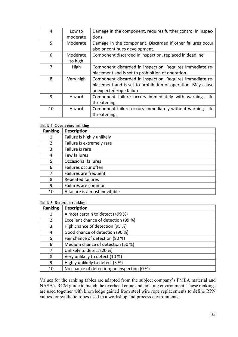
35
4 Low to moderate
Damage in the component, requires further control in inspec-tions.
5 Moderate Damage in the component. Discarded if other failures occur also or continues development.
6 Moderate to high
Component discarded in inspection, replaced in deadline.
7 High Component discarded in inspection. Requires immediate re-placement and is set to prohibition of operation.
8 Very high Component discarded in inspection. Requires immediate re-placement and is set to prohibition of operation. May cause unexpected rope failure.
9 Hazard Component failure occurs immediately with warning. Life threatening.
10 Hazard Component failure occurs immediately without warning. Life threatening.
Table 4. Occurrence ranking
Ranking Description
1 Failure is highly unlikely
2 Failure is extremely rare
3 Failure is rare
4 Few failures
5 Occasional failures
6 Failures occur often
7 Failures are frequent
8 Repeated failures
9 Failures are common
10 A failure is almost inevitable Table 5. Detection ranking
Ranking Description
1 Almost certain to detect (>99 %)
2 Excellent chance of detection (99 %)
3 High chance of detection (95 %)
4 Good chance of detection (90 %)
5 Fair chance of detection (80 %)
6 Medium chance of detection (50 %)
7 Unlikely to detect (20 %)
8 Very unlikely to detect (10 %)
9 Highly unlikely to detect (5 %)
10 No chance of detection; no inspection (0 %) Values for the ranking tables are adapted from the subject company’s FMEA material and NASA’s RCM guide to match the overhead crane and hoisting environment. These rankings are used together with knowledge gained from steel wire rope replacements to define RPN values for synthetic ropes used in a workshop and process environments.

36
4.4 Root cause analysis Root cause analysis (RCA) is used to analyse vital root causes of failure. According to Tinga’s (2012) book, Mechanism based failure analysis, RCA is not a strictly defined method, but it aims to define the deepest cause of failure. It can also be used to analyse incidents or other events. It is not used for all synthetic rope failure causes, only for the most critical ones. The analysis requires potential failure causes and cause sources. The analysis itself is typically performed by asking “why”. Therefore, the technique of “five whys” is commonly linked to RCA (Tinga, 2012). In practice, it means that the root cause of the failure is found by defining at least five levels of failure, starting from the failure under analysis. As an outcome, the analysis defines the root causes that lead to component failure. By avoiding these root causes, the failure is also prevented.
4.5 Data uncertainty Information always also contains uncertainty. According to Bergman et al. (2009), reliability data and analysis come with three types of uncertainty, that is, physical, statistical and model uncertainty. Physical uncertainty, also known as scatter, is a phenomenon that has variance in its nature, such as variation in the strength of steel. Statistical uncertainty is when assump-tions are made from a thing seen in data, such as applying variation between failure modes from a small data set to a bigger group. And the third, model uncertainty, is when a simplified relationship is used to represent actual, more complex relationships. This is typically seen in object stress calculations. (Bergman et al., 2009) In this section, data uncertainties are considered in connection with the field service data and incident reports used in this thesis. These uncertainties are of the statistical type, as intro-duced above. Identified sources of uncertainty are introduced for each data type. Together with root cause analysis, the failure mode, effects and criticality analysis is also taken into account.
4.5.1 Incident reports
The incident reports, both from the target company and OSHA, have several sources of un-certainty. The reports, especially the OSHA reports, are rather brief. The root cause can be defined. However, there is always the risk of making a mistake in the analysis or the report lacking of relevant information. In root cause analysis, there is also the risk of the analysis not being deep enough and not having the true root cause defined. The reports can also lack other relevant information concerning the lead-up to the incident. This information can be hidden either by the company or the victim because an incident can lead to penalties. The number of these reports is low, which means that a deep statistical analysis cannot be per-formed.
4.5.2 Field service data
The field service data offered by the target company has two main sources of uncertainty. The optimal rope placement task in the database would contain all required information. However, in some cases, the task fault type and comment were left unfilled. Also, several photographs of damaged ropes remained untaken, not uploaded or the picture was taken

37
from, for example, the rope certificate. The second main source of uncertainty is incorrectly filled-out information. The data contained tasks where the selected task fault did not match the task comment, and, therefore, the failure mode was selected incorrectly. These mistakes were corrected when the task comment provided valid information. However, there is a risk that the task fault is incorrectly selected and a proper comment is not given, and, therefore, the failure mode is not correct. The selection of the correct failure mode is also a source of uncertainty. A rope can have multiple failure modes at the same time but the database allows only for the selection of one. Also, there are different kind of deformation types, and, for example, bent and kinked are relatively close to each other. What counts as either bent or kinked rope, can vary between service technicians. The rope replacement tasks were categorized into three groups based on whether the failure mode was related to misuse. If the comment or service request in the rope replacement task indicated misuse, the task was categorized into the misuse group. However, there is a chance that the service technician has not recognized misuse when replacing the rope or it has not been noted down. The number of hoisting wire rope replacements was lower with Hoist B than with A or C, which can distort the results of the statistical analysis.
4.5.3 FMECA and RCA
FMECA and RCA both have some sources of uncertainty. Firstly, both types of analysis are subjective works. This has been controlled by having conversations with professionals from the subject company and asking for feedback. The selection of the FMECA ratings for se-verity, occurrence and detection is also a subjective task, and it is based on phenomena seen in the field service data analysis. The results of that analysed field service data are only suitable for steel wire ropes, and FMECA is performed for synthetic rope. The reasons for rope replacements are varied as are the ways ropes are used when shifting from steel wire to synthetic rope. Many rope failures are not only a failure of the rope because the rope and the structure and mechanisms of the hoist are bound together through such things as rope angles, rope guide design and rope sheave protection design. Therefore, what matters is not the risk priority number given by the RCA, but the identification of failure modes and their causes. This leads to a database of knowledge concerning the issues that should be taken care of when switching from steel wire to synthetic rope, and how, at the same time, to ensure the safety of that rope. Root cause analysis comes with the risk of not being able to detect all possible causes of failure. There might also be some rare root causes that occur together with other causes and which are not identified during analysis. Similarly, there is the risk that the analysis is not deep enough and the real root cause is not found.
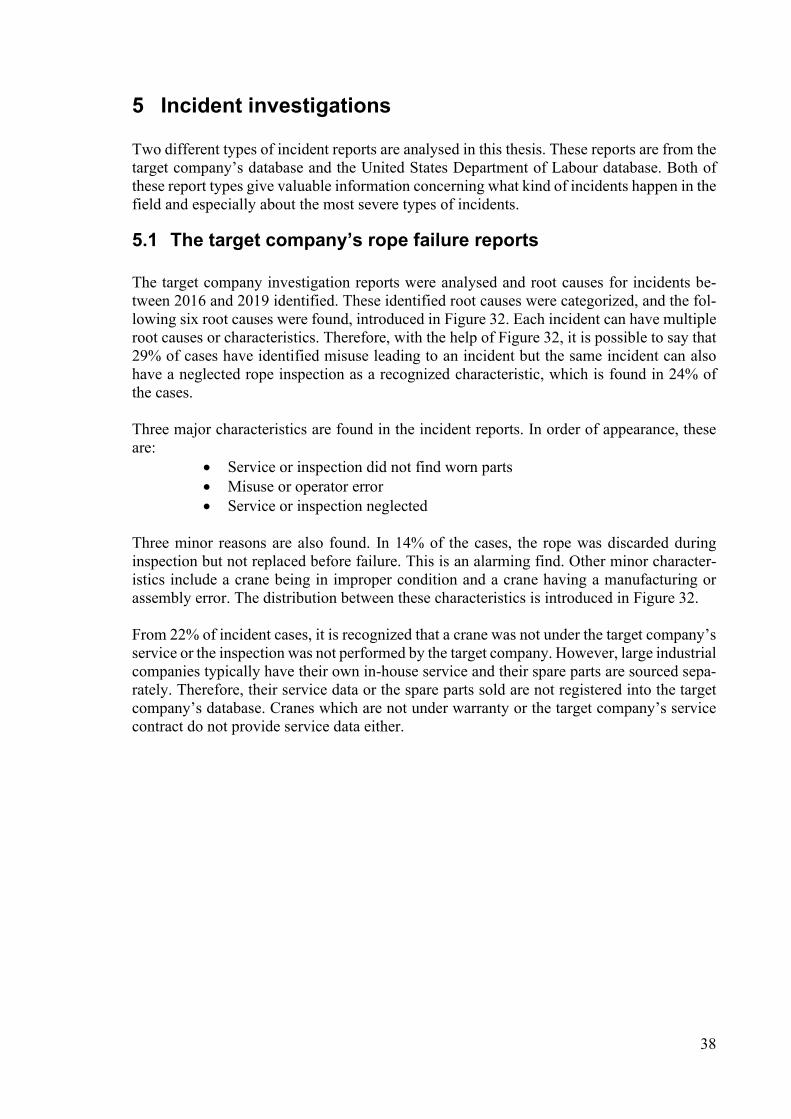
38
5 Incident investigations Two different types of incident reports are analysed in this thesis. These reports are from the target company’s database and the United States Department of Labour database. Both of these report types give valuable information concerning what kind of incidents happen in the field and especially about the most severe types of incidents.
5.1 The target company’s rope failure reports The target company investigation reports were analysed and root causes for incidents be-tween 2016 and 2019 identified. These identified root causes were categorized, and the fol-lowing six root causes were found, introduced in Figure 32. Each incident can have multiple root causes or characteristics. Therefore, with the help of Figure 32, it is possible to say that 29% of cases have identified misuse leading to an incident but the same incident can also have a neglected rope inspection as a recognized characteristic, which is found in 24% of the cases. Three major characteristics are found in the incident reports. In order of appearance, these are:
Service or inspection did not find worn parts Misuse or operator error Service or inspection neglected
Three minor reasons are also found. In 14% of the cases, the rope was discarded during inspection but not replaced before failure. This is an alarming find. Other minor character-istics include a crane being in improper condition and a crane having a manufacturing or assembly error. The distribution between these characteristics is introduced in Figure 32. From 22% of incident cases, it is recognized that a crane was not under the target company’s service or the inspection was not performed by the target company. However, large industrial companies typically have their own in-house service and their spare parts are sourced sepa-rately. Therefore, their service data or the spare parts sold are not registered into the target company’s database. Cranes which are not under warranty or the target company’s service contract do not provide service data either.
39
Figure 32. Recognized characteristics from incident reports
5.2 OSHA accident reports Altogether 8 cases from the United States Department of Labour Occupational Safety and Health Administration database were investigated in this thesis. All of the accidents were related to overhead cranes. The accidents took place between 2009 and 2017 and caused 5 fatalities and 3 hospitalisations. None of the accidents were caused by failure of the hoisting wire rope. The victims were working under a hoisted load or in the immediate vicinity of a hoisted load. When the load dropped, they were crushed by or took a hit from the load. In these cases, the load disengaged from the hook block because the lifting equipment was broken, came loose or was improperly attached. In two cases, the reason for disengagement was unclear. The following abdications of duty or carelessness were found during the anal-ysis of the accident reports:
Side pulling led to the lifting equipment to disengage from the hook block Working under an unsecured lifted load Lifting equipment was not properly attached Lifting equipment entangled with another object Unsuitable lifting equipment was chosen
These accidents underline the importance of following safety regulations.
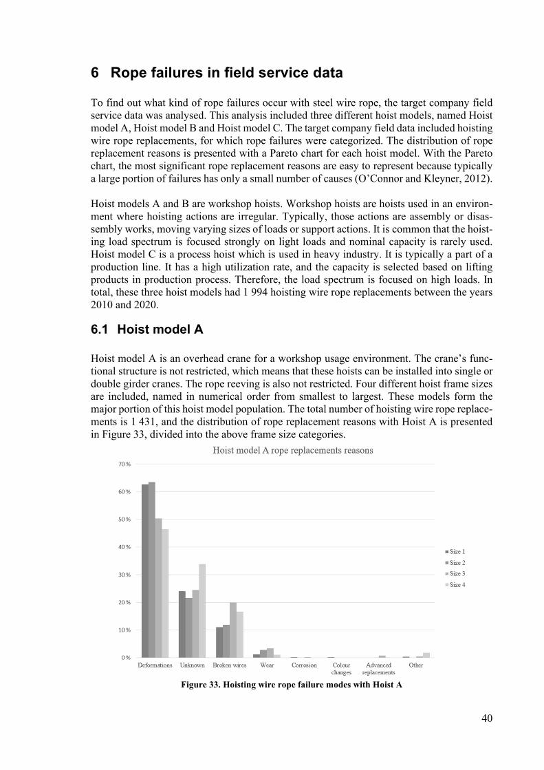
40
6 Rope failures in field service data To find out what kind of rope failures occur with steel wire rope, the target company field service data was analysed. This analysis included three different hoist models, named Hoist model A, Hoist model B and Hoist model C. The target company field data included hoisting wire rope replacements, for which rope failures were categorized. The distribution of rope replacement reasons is presented with a Pareto chart for each hoist model. With the Pareto chart, the most significant rope replacement reasons are easy to represent because typically a large portion of failures has only a small number of causes (O’Connor and Kleyner, 2012). Hoist models A and B are workshop hoists. Workshop hoists are hoists used in an environ-ment where hoisting actions are irregular. Typically, those actions are assembly or disas-sembly works, moving varying sizes of loads or support actions. It is common that the hoist-ing load spectrum is focused strongly on light loads and nominal capacity is rarely used. Hoist model C is a process hoist which is used in heavy industry. It is typically a part of a production line. It has a high utilization rate, and the capacity is selected based on lifting products in production process. Therefore, the load spectrum is focused on high loads. In total, these three hoist models had 1 994 hoisting wire rope replacements between the years 2010 and 2020.
6.1 Hoist model A Hoist model A is an overhead crane for a workshop usage environment. The crane’s func-tional structure is not restricted, which means that these hoists can be installed into single or double girder cranes. The rope reeving is also not restricted. Four different hoist frame sizes are included, named in numerical order from smallest to largest. These models form the major portion of this hoist model population. The total number of hoisting wire rope replace-ments is 1 431, and the distribution of rope replacement reasons with Hoist A is presented in Figure 33, divided into the above frame size categories.
Figure 33. Hoisting wire rope failure modes with Hoist A

41
Deformations form the majority of all failure modes. Over 60% of all Hoist model A hoisting wire rope replacements were performed because the rope was deformed and therefore dis-carded. The distribution of more specific deformation types is shown in Figure 34. The de-formation type of bending forms the majority of failure modes. The original data includes two different levels of bent rope. The light level, known as bent, and the more severe type, known as kinked. In the analysis they are combined into one because being able to identify between these two can vary. The second largest deformation type is the bird-cage, where the top layer strands loosen and form a cage, which leads to rope discard.
Figure 34. Distribution of deformation types with Hoist A
Steel wire rope failure modes introduced in section 3.2.1 are also introduced from a causal perspective. Bending fatigue causes broken wires and a worn drum and sheaves cause exter-nal wear to ropes. Deformation of the rope is mostly linked to misuse scenarios. Figure 35 presents the distribution of rope failure linked to misuse. When the failure mode is related to misuse but cannot be confirmed by the rope replacement task, it is listed as “Possible”. Only events where the misuse is confirmed by the rope replacement task comments are listed as “Yes”. Rope replacements with failure modes that are not related to misuse are listed as “No”. Figure 35 shows that the majority of rope replacements with Hoist A have a possible relationship with misuse.
Figure 35. Distribution of the relation between failure modes and misuse
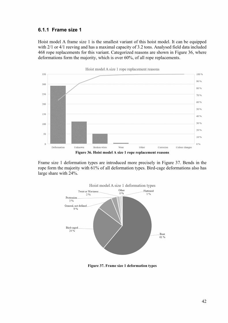
42
6.1.1 Frame size 1
Hoist model A frame size 1 is the smallest variant of this hoist model. It can be equipped with 2/1 or 4/1 reeving and has a maximal capacity of 3.2 tons. Analysed field data included 468 rope replacements for this variant. Categorized reasons are shown in Figure 36, where deformations form the majority, which is over 60%, of all rope replacements.
Figure 36. Hoist model A size 1 rope replacement reasons
Frame size 1 deformation types are introduced more precisely in Figure 37. Bends in the rope form the majority with 61% of all deformation types. Bird-cage deformations also has large share with 24%.
Figure 37. Frame size 1 deformation types
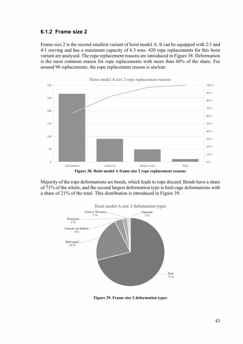
43
6.1.2 Frame size 2
Frame size 2 is the second smallest variant of hoist model A. It can be equipped with 2/1 and 4/1 reeving and has a maximum capacity of 6.3 tons. 420 rope replacements for this hoist variant are analysed. The rope replacement reasons are introduced in Figure 38. Deformation is the most common reason for rope replacements with more than 60% of the share. For around 90 replacements, the rope replacement reason is unclear.
Figure 38. Hoist model A frame size 2 rope replacement reasons
Majority of the rope deformations are bends, which leads to rope discard. Bends have a share of 71% of the whole, and the second largest deformation type is bird-cage deformations with a share of 21% of the total. This distribution is introduced in Figure 39.
Figure 39. Frame size 2 deformation types

44
6.1.3 Frame size 3
Hoist model A with frame size 3 has a total of 375 rope replacements. The rope replacement reasons are introduced in Figure 40. Frame size 3 has different reeving arrangements from 2/1 to 8/2 and a maximum capacity of 20 tons. Deformations are the most common reason for rope replacement, with a share of around 50% of the total. The second most common reason is broken wires, and there are around 90 unknown rope replacements.
Figure 40. Hoist model A size 3 rope replacement reasons
The most common type of deformation is a bend with a share of 66%. Also, bird-cage de-formations occur with a share of 20%. The distribution of different deformation types is seen in Figure 41.
Figure 41. Frame size 3 deformation types

45
6.1.4 Frame size 4
Hoist model A frame size 4 is the largest variant of hoist model A. It has a maximal hoisting capacity of 80 tons. Rope reeving arrangements vary between 2/1 and 8/2. The total number of analysed rope replacements is 168, and the replacement reasons are introduced in Figure 42. Deformation is the most common reason at around 50% of the total. Unrecognized re-placements are the second largest group with almost 60 replacements. Broken wires are the third common reason with almost 30 replacements.
Figure 42. Hoist model A size 4 rope replacement reasons
The deformation types are introduced more clearly in Figure 43, where it is seen that bends have the greatest share with 68%. Bird-cage deformations also occur, and they have a share of 14%.
Figure 43. Frame size 4 deformation types
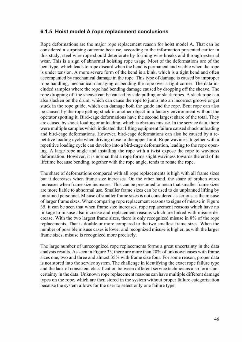
46
6.1.5 Hoist model A rope replacement conclusions
Rope deformations are the major rope replacement reason for hoist model A. That can be considered a surprising outcome because, according to the information presented earlier in this study, steel wire rope should deteriorate by forming wire breaks and through external wear. This is a sign of abnormal hoisting rope usage. Most of the deformations are of the bent type, which leads to rope discard when the bend is permanent and visible when the rope is under tension. A more severe form of the bend is a kink, which is a tight bend and often accompanied by mechanical damage in the rope. This type of damage is caused by improper rope handling, mechanical damaging or bending the rope over a tight corner. The data in-cluded samples where the rope had bending damage caused by dropping off the sheave. The rope dropping off the sheave can be caused by side pulling or slack ropes. A slack rope can also slacken on the drum, which can cause the rope to jump into an incorrect groove or get stuck in the rope guide, which can damage both the guide and the rope. Bent rope can also be caused by the rope getting stuck in another object in a factory environment without the operator spotting it. Bird-cage deformations have the second largest share of the total. They are caused by shock loading or unloading, which is obvious misuse. In the service data, there were multiple samples which indicated that lifting equipment failure caused shock unloading and bird-cage deformations. However, bird-cage deformations can also be caused by a re-petitive loading cycle when driving close to the upper limit. Rope waviness together with a repetitive loading cycle can develop into a bird-cage deformation, leading to the rope open-ing. A large rope angle and installing the rope with a twist expose the rope to waviness deformation. However, it is normal that a rope forms slight waviness towards the end of its lifetime because bending, together with the rope angle, tends to rotate the rope. The share of deformations compared with all rope replacements is high with all frame sizes but it decreases when frame size increases. On the other hand, the share of broken wires increases when frame size increases. This can be presumed to mean that smaller frame sizes are more liable to abnormal use. Smaller frame sizes can be used to do unplanned lifting by untrained personnel. Misuse of smaller frame sizes is not considered as serious as the misuse of larger frame sizes. When comparing rope replacement reasons to signs of misuse in Figure 35, it can be seen that when frame size increases, rope replacement reasons which have no linkage to misuse also increase and replacement reasons which are linked with misuse de-crease. With the two largest frame sizes, there is only recognized misuse in 8% of the rope replacements. That is double or more compared to the two smallest frame sizes. When the number of possible misuse cases is lower and recognized misuse is higher, as with the larger frame sizes, misuse is recognized more precisely. The large number of unrecognized rope replacements forms a great uncertainty in the data analysis results. As seen in Figure 33, there are more than 20% of unknown cases with frame sizes one, two and three and almost 35% with frame size four. For some reason, proper data is not stored into the service system. The challenge in identifying the exact rope failure type and the lack of consistent classification between different service technicians also forms un-certainty in the data. Unknown rope replacement reasons can have multiple different damage types on the rope, which are then stored in the system without proper failure categorization because the system allows for the user to select only one failure type.

47
6.2 Hoist model B Hoist model B is an overhead crane used in a workshop environment and it is a similar size product than Hoist model A. Three different frame size variants are included, numbered 1, 2 and 3, from smallest to largest. These models form the majority of this model population in the service database. The total number of hoisting wire rope replacements is 135. Rope replacement reasons for the hoist model B population are introduced in Figure 44 in Pareto chart form. With all three frame sizes, broken wires are the most common reason for rope replacement. The second most common reason is rope deformation. The population also includes many of unknown rope replacements, where the original reason for rope replace-ment is not known. These form a share of 10 to 30%, depending on the hoist frame size.
Figure 44. Hoisting wire rope failure modes with Hoist B
The distribution of deformation types is further introduced in Figure 45. Bends are the most common deformation type with all three frame sizes. Twists and waviness also occur with sizes 1 and 2. However, there are a lot of unspecified deformations with all frame sizes.

48
Figure 45. Distribution of deformation types with Hoist B
The distribution of failure modes related to misuse can be seen in Figure 46. In 2 to 6% of rope replacements, there is confirmed linkage to misuse. With all three frame sizes, the ma-jority of rope replacements do not have linkage between the rope replacement reason and misuse because broken wires are the most common failure mode, and broken wires are caused by bending fatigue.
Figure 46. Distribution of the relation between failure mode and misuse
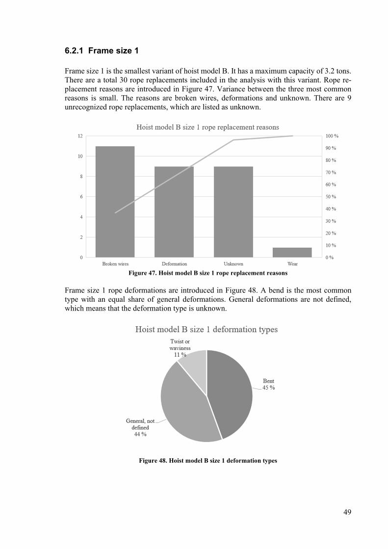
49
6.2.1 Frame size 1
Frame size 1 is the smallest variant of hoist model B. It has a maximum capacity of 3.2 tons. There are a total 30 rope replacements included in the analysis with this variant. Rope re-placement reasons are introduced in Figure 47. Variance between the three most common reasons is small. The reasons are broken wires, deformations and unknown. There are 9 unrecognized rope replacements, which are listed as unknown.
Figure 47. Hoist model B size 1 rope replacement reasons
Frame size 1 rope deformations are introduced in Figure 48. A bend is the most common type with an equal share of general deformations. General deformations are not defined, which means that the deformation type is unknown.
Figure 48. Hoist model B size 1 deformation types
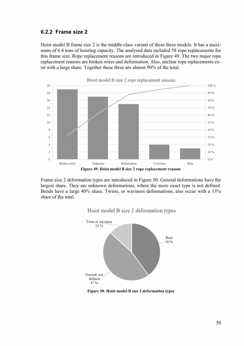
50
6.2.2 Frame size 2
Hoist model B frame size 2 is the middle-class variant of these three models. It has a maxi-mum of 6.4 tons of hoisting capacity. The analysed data included 58 rope replacements for this frame size. Rope replacement reasons are introduced in Figure 49. The two major rope replacement reasons are broken wires and deformation. Also, unclear rope replacements ex-ist with a large share. Together these three are almost 90% of the total.
Figure 49. Hoist model B size 2 rope replacement reasons
Frame size 2 deformation types are introduced in Figure 50. General deformations have the largest share. They are unknown deformations, where the more exact type is not defined. Bends have a large 40% share. Twists, or waviness deformations, also occur with a 13% share of the total.
Figure 50. Hoist model B size 2 deformation types
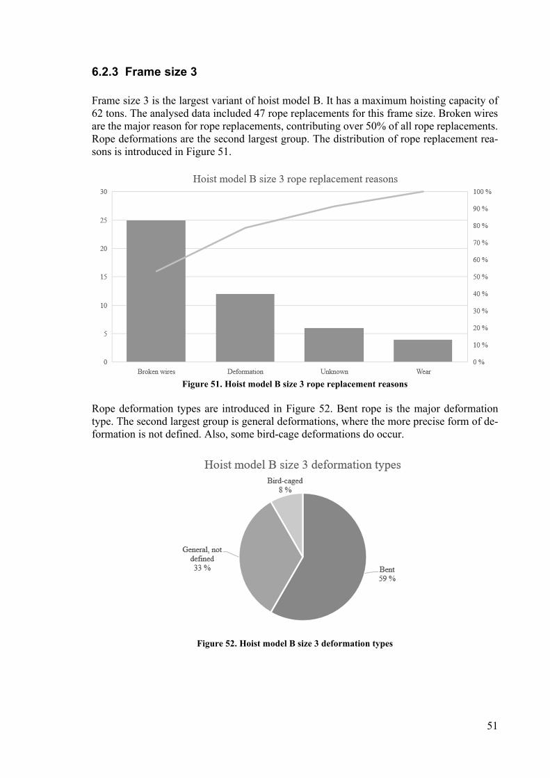
51
6.2.3 Frame size 3
Frame size 3 is the largest variant of hoist model B. It has a maximum hoisting capacity of 62 tons. The analysed data included 47 rope replacements for this frame size. Broken wires are the major reason for rope replacements, contributing over 50% of all rope replacements. Rope deformations are the second largest group. The distribution of rope replacement rea-sons is introduced in Figure 51.
Figure 51. Hoist model B size 3 rope replacement reasons
Rope deformation types are introduced in Figure 52. Bent rope is the major deformation type. The second largest group is general deformations, where the more precise form of de-formation is not defined. Also, some bird-cage deformations do occur.
Figure 52. Hoist model B size 3 deformation types
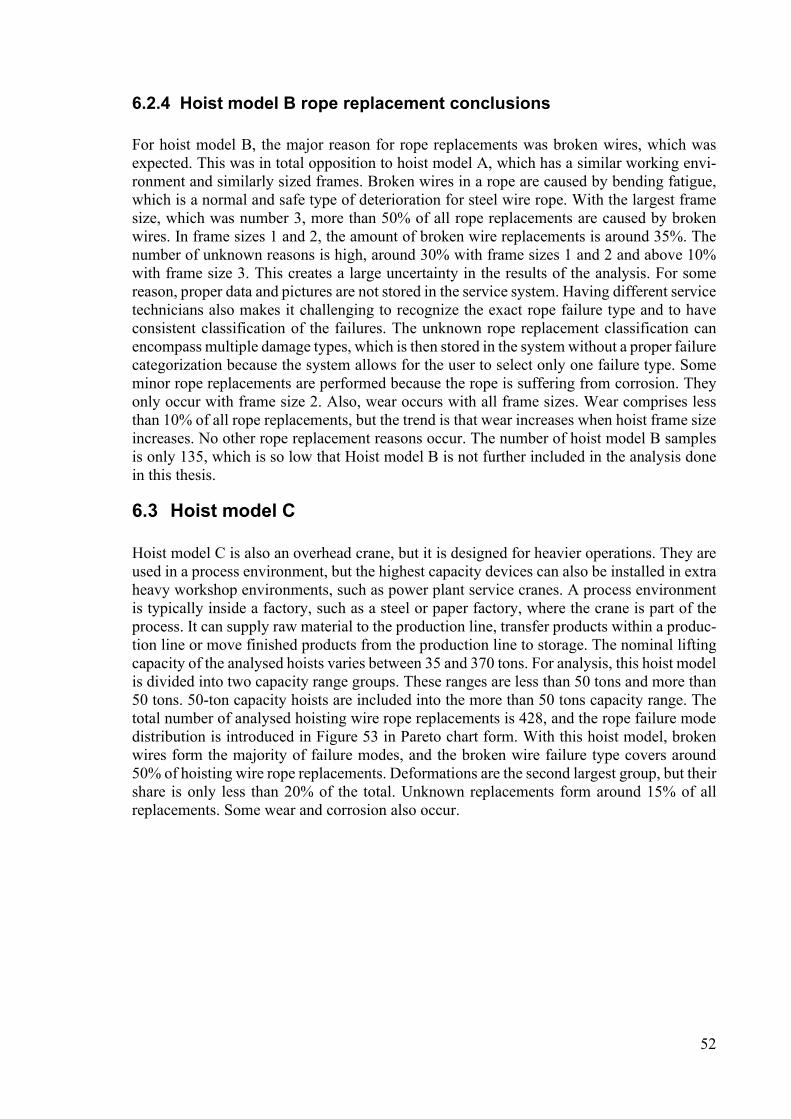
52
6.2.4 Hoist model B rope replacement conclusions
For hoist model B, the major reason for rope replacements was broken wires, which was expected. This was in total opposition to hoist model A, which has a similar working envi-ronment and similarly sized frames. Broken wires in a rope are caused by bending fatigue, which is a normal and safe type of deterioration for steel wire rope. With the largest frame size, which was number 3, more than 50% of all rope replacements are caused by broken wires. In frame sizes 1 and 2, the amount of broken wire replacements is around 35%. The number of unknown reasons is high, around 30% with frame sizes 1 and 2 and above 10% with frame size 3. This creates a large uncertainty in the results of the analysis. For some reason, proper data and pictures are not stored in the service system. Having different service technicians also makes it challenging to recognize the exact rope failure type and to have consistent classification of the failures. The unknown rope replacement classification can encompass multiple damage types, which is then stored in the system without a proper failure categorization because the system allows for the user to select only one failure type. Some minor rope replacements are performed because the rope is suffering from corrosion. They only occur with frame size 2. Also, wear occurs with all frame sizes. Wear comprises less than 10% of all rope replacements, but the trend is that wear increases when hoist frame size increases. No other rope replacement reasons occur. The number of hoist model B samples is only 135, which is so low that Hoist model B is not further included in the analysis done in this thesis.
6.3 Hoist model C Hoist model C is also an overhead crane, but it is designed for heavier operations. They are used in a process environment, but the highest capacity devices can also be installed in extra heavy workshop environments, such as power plant service cranes. A process environment is typically inside a factory, such as a steel or paper factory, where the crane is part of the process. It can supply raw material to the production line, transfer products within a produc-tion line or move finished products from the production line to storage. The nominal lifting capacity of the analysed hoists varies between 35 and 370 tons. For analysis, this hoist model is divided into two capacity range groups. These ranges are less than 50 tons and more than 50 tons. 50-ton capacity hoists are included into the more than 50 tons capacity range. The total number of analysed hoisting wire rope replacements is 428, and the rope failure mode distribution is introduced in Figure 53 in Pareto chart form. With this hoist model, broken wires form the majority of failure modes, and the broken wire failure type covers around 50% of hoisting wire rope replacements. Deformations are the second largest group, but their share is only less than 20% of the total. Unknown replacements form around 15% of all replacements. Some wear and corrosion also occur.
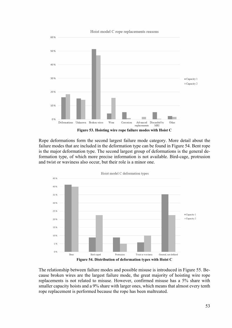
53
Figure 53. Hoisting wire rope failure modes with Hoist C
Rope deformations form the second largest failure mode category. More detail about the failure modes that are included in the deformation type can be found in Figure 54. Bent rope is the major deformation type. The second largest group of deformations is the general de-formation type, of which more precise information is not available. Bird-cage, protrusion and twist or waviness also occur, but their role is a minor one.
Figure 54. Distribution of deformation types with Hoist C
The relationship between failure modes and possible misuse is introduced in Figure 55. Be-cause broken wires are the largest failure mode, the great majority of hoisting wire rope replacements is not related to misuse. However, confirmed misuse has a 5% share with smaller capacity hoists and a 9% share with larger ones, which means that almost every tenth rope replacement is performed because the rope has been maltreated.

54
Figure 55. Distribution of the relation between failure mode and misuse
6.3.1 Capacity range 1
210 rope replacements are analysed with hoist model C in the capacity range between 35 and 50 tons. With a share of over 50%, the most common rope replacement reason is broken wires. The rope replacement reasons distribution is introduced in Figure 56. Deformations also occur as well as unknown rope placements. Unlike with other hoist models, rope re-placements are also performed because a rope is discarded through magnetic rope inspection (MRI).
Figure 56. Hoist model C capacity 1 rope replacement reasons
Capacity range 1 deformation types are introduced in Figure 57. Bends in the rope have the largest share with 41%. General unspecified deformations have the second largest share with 35%. Bird-cage deformations, strand or core protrusions and twist or waviness also occur with minor shares.
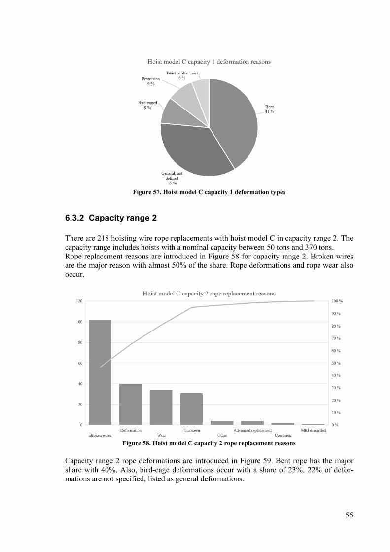
55
Figure 57. Hoist model C capacity 1 deformation types
6.3.2 Capacity range 2
There are 218 hoisting wire rope replacements with hoist model C in capacity range 2. The capacity range includes hoists with a nominal capacity between 50 tons and 370 tons. Rope replacement reasons are introduced in Figure 58 for capacity range 2. Broken wires are the major reason with almost 50% of the share. Rope deformations and rope wear also occur.
Figure 58. Hoist model C capacity 2 rope replacement reasons
Capacity range 2 rope deformations are introduced in Figure 59. Bent rope has the major share with 40%. Also, bird-cage deformations occur with a share of 23%. 22% of defor-mations are not specified, listed as general deformations.

56
Figure 59. Hoist model C capacity 2 deformation types
6.3.3 Hoist model C rope replacement conclusions
Hoist model C is a significantly larger type of overhead crane than models A and B, and it is typically used in a process environment, especially the less than 50-ton capacity devices. Larger than 50-ton devices can also be installed into heavy workshop type environments, and they typically have a more than a 100-ton capacity. Large hoisting devices are equipped with frequency controllers, which ensure smooth operation. In smaller hoist models, a two-speed contactor control is also available as a cheaper option. With larger lifting devices, the operators usually go through an introductory training, and only certain people are allowed to use the overhead crane. A trained operator has the necessary knowledge to safely operate the crane and know what the limitations of the device are. Therefore, lifting operations with larger overhead cranes are better planned, and it can be assumed that more suitable lifting equipment is used. High-capacity overhead cranes are larger investments than smaller cranes, and especially in a process environment, the availability of the crane is in high de-mand. Therefore, high-capacity cranes have a better planned service schedule and are gen-erally better cared for. As expected, broken wires are the major rope replacement reason. Broken wires are caused by bending fatigue, and it is a normal, safe and monitorable rope deterioration type. Broken wires are the cause for around 50% of the rope replacements with model C. Interestingly, overhead crane models with a higher capacity are typically equipped with a larger d/D -ratio, which means that the rope sheaves and the drum have a larger diameter compared to rope diameter. That characteristic increases rope bending fatigue lifetime. Rope deformations have a share varying between 15 and 20%. There is only slight variation between these two capacity ranges, and only wear has a large difference. But that might also be statistical vari-ance. Unknown rope replacements have a share of around 15%, which is less than with mod-els A and B. The reasons classification background is similar as with the other models. Ser-vice data is not filled properly and extensive comments and photographs are missing. There are also rope replacement reasons which do not occur with other models. Rope wear has a share, especially in the larger capacity range. Rope wear is caused by contact with the sheaves and drum. A worn sheave or drum accelerates wear. However, hoists with a higher
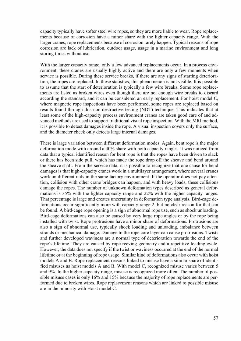
57
capacity typically have softer steel wire ropes, so they are more liable to wear. Rope replace-ments because of corrosion have a minor share with the lighter capacity range. With the larger cranes, rope replacements because of corrosion rarely happen. Typical reasons of rope corrosion are lack of lubrication, outdoor usage, usage in a marine environment and long storing times without use. With the larger capacity range, only a few advanced replacements occur. In a process envi-ronment, these cranes are usually highly active and there are only a few moments when service is possible. During these service breaks, if there are any signs of starting deteriora-tion, the ropes are replaced. In these statistics, this phenomenon is not visible. It is possible to assume that the start of deterioration is typically a few wire breaks. Some rope replace-ments are listed as broken wires even though there are not enough wire breaks to discard according the standard, and it can be considered an early replacement. For hoist model C, where magnetic rope inspections have been performed, some ropes are replaced based on results found through this non-destructive testing (NDT) technique. This indicates that at least some of the high-capacity process environment cranes are taken good care of and ad-vanced methods are used to support traditional visual rope inspection. With the MRI method, it is possible to detect damages inside the rope. A visual inspection covers only the surface, and the diameter check only detects large internal damages. There is large variation between different deformation modes. Again, bent rope is the major deformation mode with around a 40% share with both capacity ranges. It was noticed from data that a typical identified reason for bent rope is that the ropes have been driven to slack or there has been side pull, which has made the rope drop off the sheave and bend around the sheave shaft. From the service data, it is possible to recognize that one cause for bend damages is that high-capacity cranes work in a multilayer arrangement, where several cranes work on different rails in the same factory environment. If the operator does not pay atten-tion, collision with other crane bridges can happen, and with heavy loads, these collisions damage the ropes. The number of unknown deformation types described as general defor-mations is 35% with the lighter capacity range and 22% with the higher capacity ranges. That percentage is large and creates uncertainty in deformation type analysis. Bird-cage de-formations occur significantly more with capacity range 2, but no clear reason for that can be found. A bird-cage rope opening is a sign of abnormal rope use, such as shock unloading. Bird-cage deformations can also be caused by very large rope angles or by the rope being installed with twist. Rope protrusions have a minor share of deformations. Protrusions are also a sign of abnormal use, typically shock loading and unloading, imbalance between strands or mechanical damage. Damage to the rope core layer can cause protrusions. Twists and further developed waviness are a normal type of deterioration towards the end of the rope’s lifetime. They are caused by rope reeving geometry and a repetitive loading cycle. However, the data does not specify if the twist or waviness occurred at the end of the normal lifetime or at the beginning of rope usage. Similar kind of deformations also occur with hoist models A and B. Rope replacement reasons linked to misuse have a similar share of identi-fied misuses as hoist models A and B. With model C, recognized misuse varies between 5 and 9%. In the higher capacity range, misuse is recognized more often. The number of pos-sible misuse cases is only 16% and 15% because the majority of rope replacements are per-formed due to broken wires. Rope replacement reasons which are linked to possible misuse are in the minority with Hoist model C.

58
7 Analysing reliability In this section, the knowledge gained from the steel wire rope field service data is summa-rized and analysed. The replacement data is introduced in subsection 7.1. This knowledge is further used to define what kind of usage is possible to assume for synthetic rope. This is introduced in subsection 7.2, together with the FMECA tool for synthetic rope. The most critical findings of FMECA are analysed further with RCA, which is shown together with the results in subsection 7.3. Finding the most critical failure types and knowing how to avoid them is vital for controlling synthetic rope reliability in hoisting applications. Knowing these failure modes is tied together with controlling and detecting them. Without the possi-bility to detect increasing deterioration, there is no safety because the failure modes cannot be detected before a failure. Failure mode occurrence is also key information for inspectors because it is critical for them to know the signs of failure they should be looking for and what these sings say about rope usage. If abnormal failure modes keep occurring, it is im-portant to be able to identify why they are happening. Usually this is linked to misuse.
7.1 Rope replacements with steel wire rope In total, 1 994 steel wire rope replacements were analysed to find out why rope replacements were being performed. Three different hoist models, A, B and C, were included in the anal-ysis. Models A and B are workshop hoists from 3.2 to 80 tons. They were divided into sev-eral different frame sizes. Hoist model C is used in process and heavy workshop environ-ments. Model C was divided into two different capacity ranges: less than 50 tons and up from 50 tons to a maximum 370 tons. Hoist model B had only a small share of replacements with a total of 135, and, therefore, its results are not included in the analysis. However, sim-ilar rope replacements reasons occurred with model B as did with models A and C. In Figure 60, where rope replacement reasons for hoist models A and C are listed, it can be seen that there are trends. The workshop hoist model A underwent a large share of rope replacements because of rope deformations. Rope deformations also occur with hoist model C. The trend is that rope deformations occur more often with light capacity hoists, and the number of deformations decreases when capacity is increases. This contrasts with the other major rope replacement reason, which was broken wires. The share of broken wires as the replacement reason increases when frame size or hoist capacity increases. Also, rope wear occurs more often with larger frame sizes. Typically, large cranes are equipped with lower tensile grade ropes, which makes them more vulnerable to wear. There is a large share of rope replacements with no known reason. Their share varies between 14 and 34%. Minor rope replacement reasons occur with a small share. These include rope corrosion and rope colour changes and damages found during magnetic inspection. Some advanced replace-ments without rope failure also occur. The minimal share of advanced rope replacement was unexpected. However, that can be assumed to be a data entering characteristic. A service technician might place the rope in the broken wires category even though there are not enough broken wires to warrant a discard. Typically, at least one broken wire is found and the technician estimates that the rope must be replaced because it has begun to show deteri-oration and will not last until the next inspection. Technically, because the rope has not met discard criteria, the above can be categorized as an advanced replacement.

59
Figure 60. Rope replacement reasons with hoist models A and C
It was presumable that broken wires would be one of the major replacement reasons. Broken wires are one of main rope deterioration types under cyclic bending according to the ISO 4309 rope inspection standard, and the number of broken wires should be counted to define the discard limit. In the rope tests carried out by the target company, even when the working environment is controlled and there is no abnormal usage, cyclic bending still causes broken wires and eventually leads to the rope being discarded because of the broken wires. How-ever, according to the standard, rope diameter reduction should also be monitored. However, only a few rope replacements are performed because of wear. The significantly large share of rope deformations was unexpected. Rope deformations such as bending, bird-caging or a protrusion are signs of abnormal use. The variation between different deformation types is seen in Figure 61. These deformations are caused by abnormal usage such as side pulling, shock loading and unloading or driving the rope out of the sheaves or drum. Bent ropes are a typical deformation. The rope can get stuck somewhere in the working environment, causing damage to the rope. Also, shock unloading, driving ropes slack or side pulling can cause the rope to jump off the sheave and bend around the sheave shaft. The rope can also become slack on the drum and become tangled in a rope guide, which also damages the rope. These deformations are permanent damage to the rope, causing decreased minimum breaking load capacity (MBL) and ending up with the hoisting rope being discarded. Twists and further developed waviness are deformations caused by hoisting machinery geometry and rope angles. Lifting cycles tend to rotate the rope open, which causes twists. It is normal that a rope develops waviness at the end of its lifetime. However, abnormal usage can cause a rope to twist prematurely, which is not normal deterioration. Also, with high lifting heights and long lay ropes, ropes tend to rotate open. Therefore, with high lifting height configurations, rotation-resistant ropes are needed.
0%
10%
20%
30%
40%
50%
60%
70%
Rope replacement reasons hoist models A and C
Model A size 1
Model A size 2
Model A size 3
Model A size 4
Model C capacity 1
Model C capacity 2

60
Figure 61. Rope deformation types with hoist models A and C
It was noticed that an increase in hoist frame size and capacity decreased the number of rope deformations. Rope replacement reasons were categorized based on whether they had link-age to misuse or if the service data included confirmation about misuse. This distribution is seen in Figure 62. The trend is that the amount of rope replacement reasons which have a possible relation to misuse decreases when frame size increases. With higher capacity de-vices, the share of confirmed misuse cases in slightly increased, which is a sign of more precise service. On the other hand, larger hoisting devices are a more expensive investment and rope replacements have a higher cost, which leads to customers and service technicians being more interested in finding out why ropes are failing. With higher capacity devices, operators have more training and typically there are only a few people who are allowed to use a specific crane. With smaller frame sizes, there can be multiple users and training is generally light. Therefore, it can naturally be assumed that smaller frame sizes face more abnormal usage. The hoist working environment also has a strong impact. Model A and model C capacity range 2 are used in workshops, that are more diverse and less controlled operation environ-ments. Their hoisting tasks vary more and are more unique, which means that there are typ-ically no precise hoisting plans and lifting equipment. These models have more rope defor-mations, which points to abnormal use. In a process environment, hoisting tasks are part of the process and proper specialized lifting equipment is available. In a process environment, there might be automated driving tasks which are optimized and lack the human tendency for abnormal usage. In a hoisting machinery control system, there are differences depending on frame size and capacity. Since lighter devices are typically cheaper, they are equipped with a low-cost 2-speed contactor drive. As the name implies, with this controlling system, there are only two speeds, fast and slow, which leads rough hoisting speeds. Rough hoisting speeds easily lead to shock loading and unloading. Larger frame sizes and higher capacity devices are more often equipped with stepless speed frequency control drives. A frequency control drive ensures smooth operation, which decreases rope stress. A frequency converter can be equipped with shock load prevention, which continuously monitors the load and hoisting speeds and decreases hoisting speed if shock loading is noticed.
0%
10%
20%
30%
40%
50%
60%
70%
80%
Bent Bird-caged Protrusion Twist orwaviness
Flattened General,not defined
Other
Deformation types hoist models A and C
Model A size 1
Model A size 2
Model A size 3
Model A size 4
Model C capacity 1
Model C capacity 2
61
Figure 62. The relation of rope replacement reasons to misuse with hoist models A and C
It was noticed when analysing rope failure reports that in half of the cases there were mis-takes in maintenance. Either the service technician failed to notice the failure in the rope or the inspection was not performed although the crane usage required it. This loops back to how important it is to detect deterioration, identify different failure types and what causes them. To maintain safety, the inspectability of rope failure types is highlighted. For example, hoisting ropes face cyclic bending, which leads to broken wires with steel wire ropes and internal wear with synthetic ropes. If this deterioration is not detected and the decreased rope lifetime is not considered, eventually the rope will fail and drop a load. During the analysis of rope failure reports, this development was seen with multiple rope failures. Deterioration types which are not detectable with current used methods are not acceptable because then rope safety is compromised. Monitoring the development of deterioration is another ap-proach to this issue. Rope failure types must develop in a way that makes them detectable. For example, the number broken wires has to be increasing for some time before total failure. If failure occurs right after the first visible broken wire or the number of broken wires in-creases rapidly in a short period of time, the rope and its development of deterioration cannot be considered safe. This is tied to inspectability. Safe rope deterioration is when a failure type develops steadily and it can be detected with the methods currently in use.
7.2 Synthetic rope failure mode, effects and criticality analysis To apply the knowledge gained from steel wire rope replacements in the field to estimate synthetic rope failure modes, a failure mode, effects and criticality analysis is performed for synthetic rope. For the analysis, rope function is defined as: “Transforming hoisting machin-ery drum rotation into the hoisting movement of the hook block and the carrying of a load”. The analysis included the five following potential failure modes:
Broken filaments Changes in material properties Broken strand Changes in rope structure Broken rope
For each potential failure mode, effects are defined and a severity rating given to them. In the next phase, potential failure causes and cause sources are defined. Typically, FMECA

62
does not include cause sources, but in this analysis, they were used to connect deterioration types and failures to different failure modes. For these potential failure causes and their sources, an occurrence rating was given. This analysis is made for workshop and process hoists, and, the occurrence rating given is based on the occurrence of rope replacement rea-sons with steel wire rope in both environments. These steel wire rope replacement reasons are analysed and refined into usage assumptions for synthetic rope. For each potential failure cause and their sources, a current tool is defined and a rating given to each. The detection rating is given based on if the deterioration is possible to detect with the current tool before a safety-compromising failure. By multiplying the given severity, occurrence and detection ratings together, a risk priority number (RPN) is formed for each potential failure cause. FMECA tables are included as Appendix 1 in this thesis. It includes the analyses both for workshop and for process usage. For workshop usage, it is assumed that synthetic rope will face abnormal usage, such as side pulling, mechanical damage and shock loading and unloading. However, synthetic rope is more immune to this kind of abnormal usage because, based on its naturally balanced struc-ture, it will not face bird-cage rope opening. With flexible synthetic rope, permanent bends will also not be able to form on the rope. But the possibility of abnormal usage weighs heav-ier. In total, six failure causes have an RPN larger than 100, listed below. By the nature of FMECA, large RPNs are given to failure modes and causes which have immediate and se-vere consequences and low detectability.
1. Load drop caused by broken rope because of unnoticed rope deterioration (RPN: 324)
2. Severe mechanical damage causing broken rope and load drop (RPN: 200) 3. High temperature causing changes in material properties and decreased rope MBL
(RPN: 196) 4. Kink bands causing changes in rope structure causing decreased rope MBL (RPN:
150) 5. Decreased MBL by broken strand caused by internal wear (RPN: 126) 6. Decreased MBL by broken filaments caused by internal wear (RPN: 108)
For process usage, it can be assumed that synthetic rope faces more consistent use, as the major failure mode is internal wear causing broken filaments and eventually strands. In total, six failure causes have an RPN higher than 100. Numbers five and six have an equal RPN. Also, in this analysis, it is seen that failure modes and causes which have severe and imme-diate consequences together with low or more difficult detectability have higher RPNs.
1. Load drop caused by broken rope because of unnoticed rope deterioration (RPN: 324)
2. Severe mechanical damage causing broken rope and load drop (RPN: 200) 3. High temperature causing changes in material properties and decreased rope MBL
(RPN: 196) 4. Decreased MBL by broken strand caused by internal wear (RPN: 147) 5. Kink bands causing changes in rope structure causing decreased rope MBL (RPN:
120) 6. Decreased MBL by broken filaments caused by internal wear (RPN: 120)
63
In these two lists, there are only minor changes between the order of failure modes and their causes. Lower RPN values have variance because the abnormal usage of workshop hoists and the fatigue and wear of process usage are weighted against each other. However, these undetected rope deterioration mechanisms cause the greatest risks with both usage profiles. With both usage profiles, rope deterioration types which can be noticed through external inspection and do not cause immediate risk have unremarkable RPN values. These are ex-ternal wear, flex fatigue damages, chemical contamination and twists in the rope. External damages such as external wear, flex fatigue damage and cut strands can be caused by abnor-mal usage, which occurred often with steel wire ropes in workshop usage as deformations in the rope. However, synthetic rope does not have similar deformation failure modes as steel wire rope because it has a naturally balanced structure, which does not open and has natural flexibility, which makes it resistant to bends. Therefore, rope failures caused by defor-mations are not give RPN values with synthetic rope. These FMECA tables and their findings are based on occurrence knowledge and the usage environments of steel wire rope. To develop this analysis further, synthetic rope field service data should be used to update the table when such data becomes available, which would decrease the uncertainties in the analysis.
7.3 Ensuring the reliability and safety of synthetic rope This section aims to find out what should be considered when shifting from steel wire rope to synthetic rope to maintain rope reliability and safety. Using root cause analysis, causes for rope failures are analysed from the hoist usage and usage environment perspectives. This aims to find particular information regarding what should be avoided when using synthetic rope and what should be monitored carefully during inspections. In the failure mode, effects and criticality analysis, each failure mode and its cause were analysed and a risk priority number was issued. Failure modes and their causes with high RPN values are the most crit-ical ones. From these critical failure modes and causes, the following ones were selected for further analysis. For further analysis, root cause analysis is performed to identify risk factors and, therefore, develop the knowledge to avoid them.
Internal wear causing broken filaments and eventually broken strands High temperatures causing changes in rope properties Mechanical damage causing broken rope or broken strands Unnoticed rope deterioration causing broken rope
Six different failure modes were selected based on the RPN. However, it is seen that the same mechanism, internal wear, is behind broken filaments and eventually broken strands. Therefore, the failure modes are combined to the four points above. Mechanical damage causing broken strands or causing completely broken rope has the same mechanism as well. Therefore, they are also combined into one. Root cause analysis (RCA) diagrams can be found in Appendix 2. Separate analyses are performed for internal wear causing broken filaments and eventually broken strands, high temperature causing changes in rope material properties and synthetic rope failure caused by broken rope. In the analyses, causes for failure mode are looked for. This is done by asking why and following the ensuing logical chain. After several further steps in the chain are achieved, root causes can be found.

64
The following findings are from the root cause analysis. These findings are significant, es-pecially to service technicians and inspectors, in order to locate rope deterioration.
Impurities from a dusty environment or leaked oil or grease can be transported inside the rope, leading to accelerated internal wear. Particles from the sheaves or rope drum can also penetrate the rope. Particular interest must be paid to the internal inspection of the rope if impurities exist in the environment or if the rope surface has signs of impurities.
Contact friction can form heat and cause material changes to the rope. Therefore, particular attention must be paid to make sure the rope guide or other surfaces are not dragging against the rope.
External heat sources can escape attention in the ceiling of the usage environment. Lighting or heating elements can radiate excessive amounts of heat, leading to mate-rial changes if the bridge and the hoist are kept next to them.
Applying direct excessive heat, for example, from flame cutting or an electric arc, must be avoided to protect the rope from melting. If excessive heat occurs, the rope must be immediately inspected.
Contact with sharp objects or heavy sliding contact can cause the rope to be cut or slashed. These must be avoided. If a cut or slash occurs, the rope must be immedi-ately inspected.
Crossing over from steel wire to synthetic rope requires training in order to detect relevant failure modes and estimate the severity of rope deterioration. The failure modes monitored during inspections are different for synthetic rope than steel wire rope, and the same applies to the rate of rope deterioration. Knowledge of synthetic rope failure modes and their severity is critical for estimating the rope’s safe working period.
Attention must be paid when defining the inspection interval when the working en-vironment or the real utilization rate are not known. The defined inspection interval cannot be neglected because it risks rope deterioration going unnoticed. Also, it is critical that synthetic rope inspection includes both internal and external inspection phases.
7.4 Differences from the reliability and safety perspective This section aims to sum the differences between steel wire and synthetic rope found from the reliability and safety perspective and gives answers to research question “What should be considered when shifting from steel wire to synthetic rope?”. The differences can be found in Table 6. Other differences, such as price, also exist but are left out. The comparison only focuses on differences from the inspection, failure modes and field usage perspective. Table 6. Comparison between steel wire and synthetic rope in hoisting actions
Characteristic Steel wire rope Synthetic rope
Failure mode for cyclic bending fatigue
Broken wires occur. Broken filaments form fuzz.
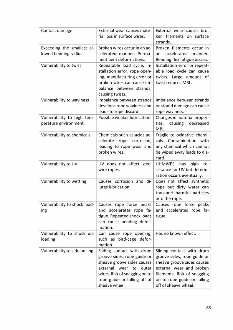
65
Contact damage External wear causes mate-rial loss in surface wires.
External wear causes bro-ken filaments on surface strands.
Exceeding the smallest al-lowed bending radius
Broken wires occur in an ac-celerated manner. Perma-nent bent deformations.
Broken filaments occur in an accelerated manner. Bending flex fatigue occurs.
Vulnerability to twist Repeatable load cycle, in-stallation error, rope open-ing, manufacturing error or broken wires can cause im-balance between strands, causing twists.
Installation error or repeat-able load cycle can cause twists. Large amount of twist reduces MBL.
Vulnerability to waviness Imbalance between strands develops rope waviness and leads to rope discard.
Imbalance between strands or strand damage can cause rope waviness.
Vulnerability to high tem-perature environment
Possible weaker lubrication. Changes in material proper-ties, causing decreased MBL.
Vulnerability to chemicals
Chemicals such as acids ac-celerate rope corrosion, leading to rope wear and broken wires.
Fragile to oxidative chemi-cals. Contamination with any chemical which cannot be wiped away leads to dis-card.
Vulnerability to UV UV does not affect steel wire ropes.
UHMWPE has high re-sistance for UV but deterio-ration occurs eventually.
Vulnerability to wetting Causes corrosion and di-lutes lubrication.
Does not affect synthetic rope but dirty water can transport harmful particles into the rope.
Vulnerability to shock load-ing
Causes rope force peaks and accelerates rope fa-tigue. Repeated shock loads can cause bending defor-mation.
Causes rope force peaks and accelerates rope fa-tigue.
Vulnerability to shock un-loading
Can cause rope opening, such as bird-cage defor-mation.
Has no known effect.
Vulnerability to side pulling Sliding contact with drum groove sides, rope guide or sheave groove sides causes external wear to outer wires. Risk of snagging on to rope guide or falling off of sheave wheel.
Sliding contact with drum groove sides, rope guide or sheave groove sides causes external wear and broken filaments. Risk of snagging on to rope guide or falling off of sheave wheel.

66
Vulnerability to flattening or crushing
Mechanical damage, core failure or multilayer spool-ing can cause crushing or flattening, which leads to discard.
Flexible structure, does not affect load bearing capabil-ity.
Rotation resistance Tends to open with high lift-ing heights. Rotation re-sistant ropes for special ap-plications.
Naturally in balance.
Inspection methods External visual inspection or MRI.
External and internal visual inspection.
Lubrication Required to protect rope from corrosion and reduce internal friction.
Not required.

67
8 Conclusions This section is for summarizing the research and its key findings. In the beginning of the theory part, ropes in hoisting applications were introduced as well as the structure of a hoist. Structures of steel wire ropes and synthetic ropes used in hoisting applications were intro-duced together with their main design features. Further in the theory part, factors affecting rope lifetime were introduced. At the end of the theory part, a rope inspection process was introduced together with failure modes for both steel wire rope and synthetic rope. In the failure modes and inspection section, the types of change that should be monitored in the ropes were explained. With steel wire rope, the following failure modes are of concern: bro-ken wires, decrease in rope diameter, corrosion and rope deformations. For synthetic rope, the three following failure more categories are of concern: wear, mechanical damage and environmental damage. In section 4, used research methods, data sources and their uncertainties were introduced. The main sources of uncertainty are insufficient or unclear entries in the data and the sub-jectivity of the analyses performed with the data. Incidents occurring in the field were inves-tigated in section 5. Through the target company’s rope failure reports, causes for rope fail-ures were investigated. The main reasons found are misuse, such as overloading, and either neglected rope inspections or rope damage was not noticed during inspection. An alarming find was that there are also rope failures because customers kept using ropes which were already discarded. Findings from the target company’s rope failure reports point out that both rope inspectability and rope remaining lifetime communication have significant roles in safety. OSHA accident reports were also analysed, and the main reasons for accidents were categorized. None of the accidental load drops mentioned in the OSHA reports were linked to rope failure, but failing lifting equipment and the load unfastening from the hook or lifting sling did occurred. These were used to build knowledge regarding the kind of in-cidents that occur in the field and what kind of factors compromise safety. However, a direct application to estimate the risks involved with synthetic rope usage was not found in this research. The target company’s field service data was analysed to gain knowledge regarding what kind of rope failures occur in the field and to refine that knowledge into reasonable assumptions regarding the kind of usage synthetic rope will face in the field. Three different hoist models were analysed: Model A with four different frame sizes, Model B with three different frame sizes and Model C with two different capacity ranges. As assumed from the literature re-search, the main failure mode for steel wire ropes in the field is broken wires. Broken wires are caused by natural fatigue when the rope is bent over the sheaves during lifting movement. Surprisingly, rope deformations occur often with hoists in the workshop environment, which is a sign of abnormal usage and lack of training. Shock loading and unloading cause rope opening and bends. Side pulling can damage the rope guide, leading to tangled rope or a drop off of the sheave. A trend was noticed where broken wires as a result of rope fatigue increased when frame sizes and capacity increased. Based on the field data, another wit-nessed trend was that deformations caused by abnormal usage are more common in work-shop than process usage hoists, and their share increases when hoist frame size decreases. Other failure modes, such as rope wear and corrosion, hardly occurred. The share of un-known rope replacements was rather large, varying between approximately 15 and 35%, which caused uncertainty in the results of the analysis. Precise data gathering, with exact

68
entries and photographs, has a very important role in performing future analyses. Its im-portance increases when the role of data analyses and digital twins increases. Based on these learnings from steel wire rope field service data, future usage of synthetic hoisting rope was analysed with FMECA and occurrences for synthetic rope failures were evaluated. For the most essential found failure modes, root cause analysis was performed to identify and minimize the factors causing damage. The internal wear of rope, cut rope and decreased load bearing capacity caused by high temperatures are identified as the most crit-ical failure modes for synthetic rope. Based on these findings, root cause analysis was per-formed to find root causes for these potential high-risk failures. By having knowledge of the root causes, they can be avoided. Multiple root causes were found with RCA, such as exter-nal heat sources from lighting and heating, particles from drum material or from dirty water ending up in the rope and improperly performed internal inspections. Finally, in the analysis of reliability, the found significant differences between steel wire and synthetic rope were introduced. These differences are concerning from the perspective of reliability and safety. This research provides two significant findings. Steel wire ropes are discarded in the field because they have deformation changes. This is unexpected because lifting cycles cause bending fatigue, leading to broken wires, whereas rope deformation is caused by abnormal usage. The second main finding is that based on the analyses, synthetic rope is not as vul-nerable to deformations caused by abnormal usage as steel wire rope. Therefore, the risks that synthetic rope faces in the field can only be detected through changes in the rope struc-ture. In the future, there are two clear focus areas for further research. The first is that the devel-opment of the target company’s field data should be continued to be able to perform more precise analyses. Unambiguous data entries are needed together with photographs. When enough field data from synthetic rope usage and replacements is gathered, similar failure cause analyses should be performed. The nature of FMECA demands that rating numbers are updated with the best possible available data to gain more precise results. When synthetic rope field data is available, it should be used to update the FMECA rating numbers. The second area is to develop methods to inspect synthetic rope for environmental deterioration. For example, research regarding what kind of changes high temperatures below the melting point of the rope as well as UV radiation cause for synthetic rope and how to detect them. Also, investigations by functional tests of how synthetic rope acts under shock loads and shock unloads should be performed to find out if there are noticeable changes in rope struc-ture.

69
9 References Anthoni, J. M. (2018) Ensuring crane reliability by utilizing the life cycle data of its digital twin. Aalto University. Bergman, B. et al. (2009) Robust Design Methodology for Reliability : Exploring the Effects of Variation and Uncertainty. John Wiley & Sons, Incorporated. Birolini, A. (2010) Reliability Engineering : theory and practice. 6th Editio. Berlin: Springer. Bunsell, A. R. (2009) Handbook of tensile properties of textile and technical fibres. Cambridge, UK: Woodhead Publishing Limited in association with The Textile Institute. Chang, X. Dong et al. (2020) ‘Friction, wear and residual strength properties of steel wire rope with different corrosion types’, Wear. Elsevier B.V., 458–459(April), p. 203425. doi: 10.1016/j.wear.2020.203425. Finnish Standards Association (2005) ‘SFS-EN ISO 1968 Fibre ropes and cordage. Vocabulary’. Finnish Standards Association (2012a) ‘SFS-EN 10264-3 STEEL WIRE AND WIRE PRODUCTS. STEEL WIRE FOR ROPES. PART 3: ROUND AND SHAPED NON ALLOYED STEEL WIRE FOR HIGH DUTY APPLICATIONS’. Finnish Standards Association (2012b) ‘SFS-ISO 4309 CRANES. WIRE ROPES. CARE AND MAINTENANCE, INSPECTION AND DISCARD’. Finnish Standards Association (2013) ‘EN13135:2013 Cranes. Safety. Design. Requirements for equipment’. Finnish Standards Association (2018) ‘ISO 10325:2018 Fibre ropes. High modulus polyethylene. 8-strand braided ropes, 12-strand braided ropes and covered ropes’. Finnish Standards Association (2019a) ‘ISO 9554:2019 Fibre ropes. General specifications’. Finnish Standards Association (2019b) ‘SFS-EN 14492-2 : 2019 Cranes . Power driven winches and hoists . Part 2 : Power driven hoists Nosturit . Konekäyttöiset vinssit ja nostimet . Osa 2 : Konekäyttöiset nostimet’. Fu, J., Jin, Z.-M.,; Wang, J.-W. (2019) UHMWPE Biomaterials for Joint Implants. Singapore: Springer. Grofsmederij Nieuwkoop B.V. (2020) GN Rope Fittings. Available at: https://gnweb.com/online-catalogue/sockets (Accessed: 8 May 2020). Hoist Zone (2020) Yale YK Electric Wire Rope Hoist & Trolley. Available at: https://hoistzone.com/shop/yale-yk-electric-wire-rope-hoist/ (Accessed: 6 March 2020).

70
Industrial Magza (2020) Rope reeving arrangements, Industrial Magza. Available at: https://www.industrialmagza.com/pdf/detroit hoist/Literature9-MGZ.pdf. Jomdecha, C. and Prateepasen, A. (2009) ‘Design of modified electromagnetic main-flux for steel wire rope inspection’, NDT and E International, 42(1), pp. 77–83. doi: 10.1016/j.ndteint.2007.10.006. Liebherr (2020) High-tensile fibre rope for tower cranes; Fibre cranes: lightweight to increase lifting capacity. Available at: https://www.liebherr.com/en/int/products/high-strength-fibre-rope-solite/fibre-rope.html (Accessed: 24 October 2020). Linnainmaa, P. (2014) Ensuring crane reliability under various environmental conditions. Tampere University of Technology. Mazella Companies (2018) What is Wire Rope? Understanding the Specifications and Construction. Available at: https://www.mazzellacompanies.com/Resources/Blog/what-is-wire-rope-specifications-classifications-construction (Accessed: 8 May 2020). Mazzella Companies (2018) What is Wire Rope ? Understanding the Specifications and Construction Components of Wire Rope. Available at: https://www.mazzellacompanies.com/Resources/Blog/what-is-wire-rope-specifications-classifications-construction (Accessed: 8 May 2020). McKenna, H. A., Hearle, J. W. S. and O’Hear, N. (2004) Handbook of fibre rope technology. Cambridge, England: Woodhead Publishing Limited in association with The Textile Institute. O’Connor, P. and Kleyner, A. (2012) Practical Reliability Engineering, 5th Edition. 5th Editio. Chichester, United Kingdom: John Wiley & Sons 2012. Onur, Y. A., İmrak, C. E. and Onur, T. Ö. (2019) ‘Discarding lifetime investigation of a rotation resistant rope subjected to bending over sheave fatigue’, Measurement: Journal of the International Measurement Confederation, 142, pp. 163–169. doi: 10.1016/j.measurement.2019.04.078. Peltoranta, V. (2014) Reliability of hoist as a part of design process. Aalto University. Peterka, P. et al. (2014) ‘Failure analysis of hoisting steel wire rope’, Engineering Failure Analysis. Elsevier Ltd, 45, pp. 96–105. doi: 10.1016/j.engfailanal.2014.06.005. Pynnönen, A. (2019) Induction motor reliability in hoisting applications. Tampere University. Röksä, T. (2015) Field data in reliability modelling of a hoist. Aalto University. Rotor Cranes (2013) Wire Rope - Lay and Drum Winding. Available at: http://w.hoistcraneparts.com/parts/wire-rope/wire-rope-lay-and-drum-winding.php (Accessed: 8 May 2020).

71
Samson Rope Technologies (2016a) ‘Effect of Ultraviolet Light on K-100’. Available at: https://samsonrope.com/resources/technical-documents. Samson Rope Technologies (2016b) ‘Impact of Elevated Temperatures on K-100 Synthetic Crane Hoist Line’. Available at: https://samsonrope.com/resources/technical-documents. Samson Rope Technologies (2018) ‘The Effect of Twist on Braided Ropes’. Available at: https://samsonrope.com/resources/technical-documents. Samson Rope Technologies (2020) ‘Rope Inspection and Retirement’. Available at: https://samsonrope.com/resources/technical-documents. Tinga, T. (2012) Mechanism Based Failure Analysis. Nederlandse Defensie Academie. Tinga, T. (2013) Principles of loads and failure mechanisms; Applications in maintenance, reliability and design, Springer Series in Reliability Engineering. United States Department of Labour Occupational Safety and Health Administration (2020) OSHA Injury and Illness Recordkeeping and Reporting Requirements. Available at: https://www.osha.gov/recordkeeping/#recordable_definition (Accessed: 4 September 2020). Valli, T. (2015) Ensuring reliability of hoist brake. Tampere University of Technology. Vanguard Steel Ltd. (2013) Wire Ropes. Available at: http://qualitysales.ca/wp-content/uploads/2013/11/QSSrigging_catalogue.pdf (Accessed: 8 May 2020). Wikimedia Commons (2014) 6x19 wire rope construction. Available at: https://commons.wikimedia.org/wiki/File:6x19_wire_rope_construction.svg (Accessed: 28 February 2020). Wire Rope Technical Board (2005) Wire Rope Users Manual. 4th edn. Alexandria. Wire Rope Technology Aachen (2018) ‘Calculating the service life of running steel wire ropes’. Available at: http://www.ropetechnology.com/bro_engl/Bro_Lebensdauer_en.pdf.

72
10 List of appendices Appendix 1. FMECA tables. 2 pages. Appendix 2. RCA diagrams. 3 pages.
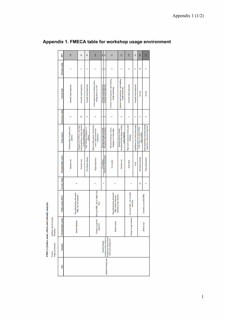
Appendix 1 (1/2)
1
Appendix 1. FMECA table for workshop usage environment

2
Appendix 1. FMECA table for process usage environment
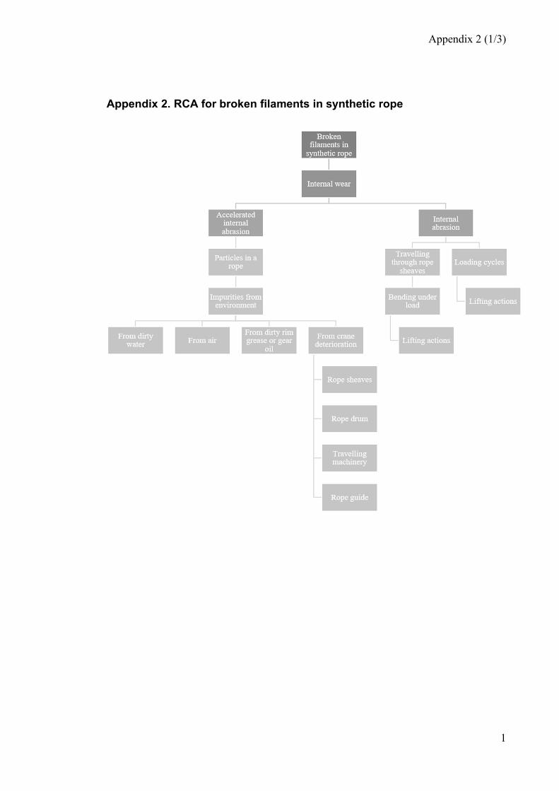
Appendix 2 (1/3)
1
Appendix 2. RCA for broken filaments in synthetic rope

Appendix 2 (2/3)
2
Appendix 2. RCA for changes in synthetic rope material properties
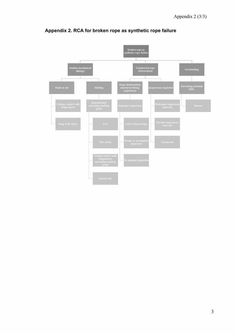
Appendix 2 (3/3)
3
Appendix 2. RCA for broken rope as synthetic rope failure


![FIBRE ROPES - FlintAlso see Barrier Rope [page 183] for an alternative soft 3-strand decorative rope. Artificial Hemp A natural coloured 3-strand synthetic rope with a similar feel](https://static.fdocuments.in/doc/165x107/603b094dbed41e1e42756f46/fibre-ropes-also-see-barrier-rope-page-183-for-an-alternative-soft-3-strand.jpg)