Difference between most common commercial contact angle ... between... · Difference between most...
17
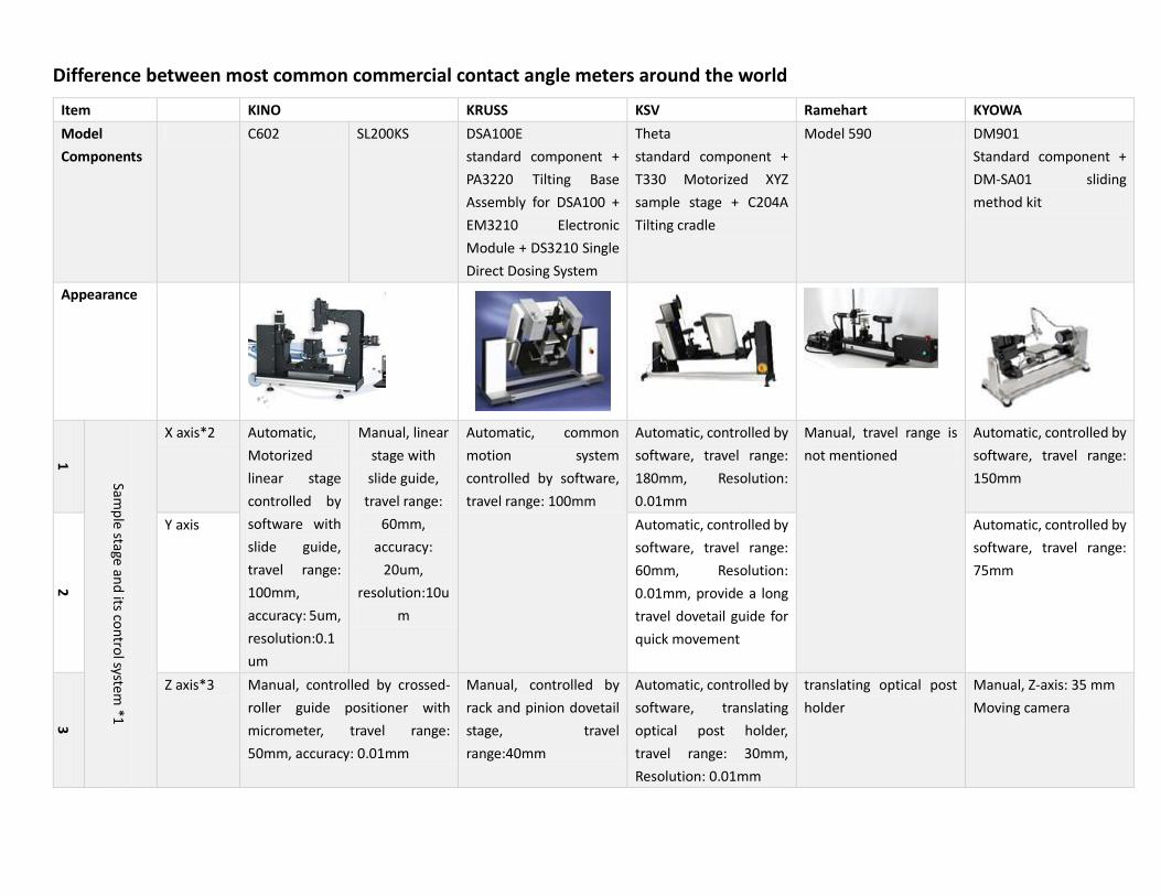
Difference between most common commercial contact angle meters around the world Item KINO KRUSS KSV Ramehart KYOWA Model Components C602 SL200KS DSA100E standard component + PA3220 Tilting Base Assembly for DSA100 + EM3210 Electronic Module + DS3210 Single Direct Dosing System Theta standard component + T330 Motorized XYZ sample stage + C204A Tilting cradle Model 590 DM901 Standard component + DM-SA01 sliding method kit Appearance 1 Sample stage and its control system *1 X axis*2 Automatic, Motorized linear stage controlled by software with slide guide, travel range: 100mm, accuracy: 5um, resolution:0.1 um Manual, linear stage with slide guide, travel range: 60mm, accuracy: 20um, resolution:10u m Automatic, common motion system controlled by software, travel range: 100mm Automatic, controlled by software, travel range: 180mm, Resolution: 0.01mm Manual, travel range is not mentioned Automatic, controlled by software, travel range: 150mm 2 Y axis Automatic, controlled by software, travel range: 60mm, Resolution: 0.01mm, provide a long travel dovetail guide for quick movement Automatic, controlled by software, travel range: 75mm 3 Z axis*3 Manual, controlled by crossed- roller guide positioner with micrometer, travel range: 50mm, accuracy: 0.01mm Manual, controlled by rack and pinion dovetail stage, travel range:40mm Automatic, controlled by software, translating optical post holder, travel range: 30mm, Resolution: 0.01mm translating optical post holder Manual, Z-axis: 35 mm Moving camera
-
Upload
phungkhanh -
Category
Documents
-
view
222 -
download
4
Transcript of Difference between most common commercial contact angle ... between... · Difference between most...
Difference between most common commercial contact angle meters around the world
Item KINO KRUSS KSV Ramehart KYOWA
Model
Components
C602 SL200KS DSA100E
standard component +
PA3220 Tilting Base
Assembly for DSA100 +
EM3210 Electronic
Module + DS3210 Single
Direct Dosing System
Theta
standard component +
T330 Motorized XYZ
sample stage + C204A
Tilting cradle
Model 590 DM901
Standard component +
DM-SA01 sliding
method kit
Appearance
1
Samp
le stage and
its con
trol system
*1
X axis*2 Automatic,
Motorized
linear stage
controlled by
software with
slide guide,
travel range:
100mm,
accuracy: 5um,
resolution:0.1
um
Manual, linear
stage with
slide guide,
travel range:
60mm,
accuracy:
20um,
resolution:10u
m
Automatic, common
motion system
controlled by software,
travel range: 100mm
Automatic, controlled by
software, travel range:
180mm, Resolution:
0.01mm
Manual, travel range is
not mentioned
Automatic, controlled by
software, travel range:
150mm
2
Y axis Automatic, controlled by
software, travel range:
60mm, Resolution:
0.01mm, provide a long
travel dovetail guide for
quick movement
Automatic, controlled by
software, travel range:
75mm
3
Z axis*3 Manual, controlled by crossed-
roller guide positioner with
micrometer, travel range:
50mm, accuracy: 0.01mm
Manual, controlled by
rack and pinion dovetail
stage, travel
range:40mm
Automatic, controlled by
software, translating
optical post holder,
travel range: 30mm,
Resolution: 0.01mm
translating optical post
holder
Manual, Z-axis: 35 mm
Moving camera
4
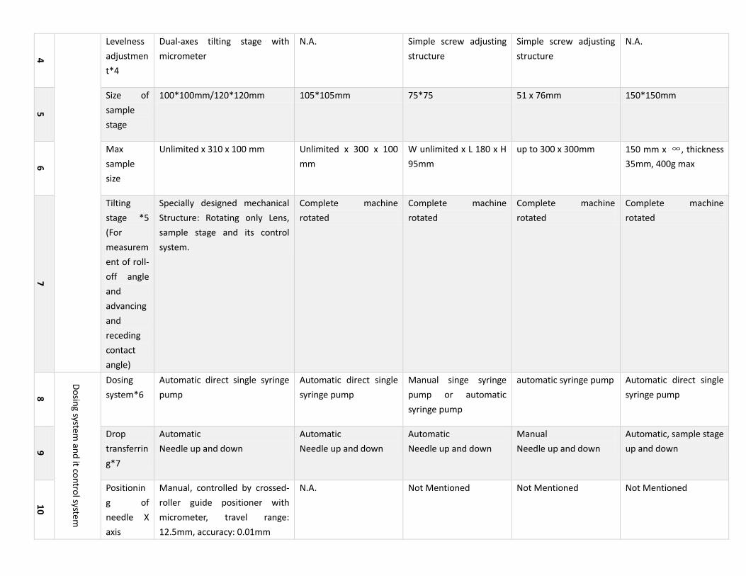
Levelness
adjustmen
t*4
Dual-axes tilting stage with
micrometer
N.A. Simple screw adjusting
structure
Simple screw adjusting
structure
N.A.
5
Size of
sample
stage
100*100mm/120*120mm 105*105mm 75*75 51 x 76mm 150*150mm
6
Max
sample
size
Unlimited x 310 x 100 mm Unlimited x 300 x 100
mm
W unlimited x L 180 x H
95mm
up to 300 x 300mm 150 mm x ∞, thickness
35mm, 400g max
7
Tilting
stage *5
(For
measurem
ent of roll-
off angle
and
advancing
and
receding
contact
angle)
Specially designed mechanical
Structure: Rotating only Lens,
sample stage and its control
system.
Complete machine
rotated
Complete machine
rotated
Complete machine
rotated
Complete machine
rotated
8
Do
sing system
and
it con
trol system
Dosing
system*6
Automatic direct single syringe
pump
Automatic direct single
syringe pump
Manual singe syringe
pump or automatic
syringe pump
automatic syringe pump Automatic direct single
syringe pump
9
Drop
transferrin
g*7
Automatic
Needle up and down
Automatic
Needle up and down
Automatic
Needle up and down
Manual
Needle up and down
Automatic, sample stage
up and down
10
Positionin
g of
needle X
axis
Manual, controlled by crossed-
roller guide positioner with
micrometer, travel range:
12.5mm, accuracy: 0.01mm
N.A. Not Mentioned Not Mentioned Not Mentioned

11
Focus
distance
adjustmen
t
N.A. Not Mentioned Not Mentioned Not Mentioned
12
Visio
n system
Camera*8 1/1.8" HD and
high speed
camera (Image
resolution:128
0*1024,
Speed: 60FPS
(1280*1024)-
119FPS(640*5
12)-
221FPS(320*2
56)-
427FPS(800*1
20); USB3.0)
1/3" HD and
high speed
camera (Image
resolution:752
*480, Speed:
87FPS
(752*480)-
340FPS(752*1
20); USB2.0)
1/2" VGA camera, Image
resolution: 780*580,
speed: 61FPS
(780×580)- 73FPS
(780×480)-212FPS
(780×120)-
311FPS(780×60);
IEEE1394b interface;
IEEE1394b PCI express
card must be needed.
1/2" VGA camera, Image
resolution: 640 x 480,
Speed: 60 FPS (640*480)
(Or choose camera
model A602 656*491
100FPS)
IEEE1394b interface;
IEEE1394b PCI express
card must be needed.
1/3" VGA camera,
Image resolution:
768x494, 70FPS
IEEE1394a interface;
IEEE1394a PCI express
card must be needed.
VGA camera, Standard
camera with speed max.
60fps
13
Lens*9 Telecentric
Lens
Field of view
with 1/2"
camera: 3.5 ...
22.8 mm
diagonal.
(about 0.5X)
Zoom Lens
Field of view
with 1/2"
camera: 3.5 ...
22.8 mm
diagonal.
(about 0.5X)
Common zoom lens 0.5X
Field of view with 1/2"
camera: 3.2 ... 22 mm
diagonal. (about 0.5X)
Common zoom lens
Field of view with 1/2"
camera: 2...12.8 mm
diagonal. (about 1X)
Fixed focus lens 3 Step Zoom lens, field
of view (width -6.6mm,
11.8mm, 17.0mm,
about 8.25,
14.75,21.25mm
diagonal) (about 0.24X,
0.18X)
14
Tilted
angle of
camera
Manual,
controlled by
micrometer
Manual,
controlled by
micrometer
Manual, controlled by
micrometer
N.A. N.A. N.A.

15
Backgroun
d Light*9
parallel light
background
light
LED light with
adjustable
brightness
LED
background
light with
adjustable
brightness
halogen illumination
with adjustable
brightness
diffuse light
LED light with adjustable
brightness,
diffuse light
Variable Fiber Optic
Illuminator
tungsten lamp with
adjustable brightness
diffuse light
16
Softw
are
Calculatin
g method
of contact
angle
Auto
calculating
θ/2 (WH), circle fitting , ellipse
fitting , curve ruler (tangent
fitting ), Spline curve-fitting , and
Young-Laplace equation fitting
(RealDrop)
WH method, Tangent
method ( composite
curve
“y=a+bx+cx0,5+d/lnx+e/x2“ used only in Kruss’s
software, ellipse fitting),
Circle fitting, Young-
Laplace equation fitting
(>30°)
Circular fit, Polynomial
fit, Young-Laplace
Circle method,
extrapolated Secant
method, Line method,
full Drop method
(Young-Laplace equation
fitting) (>45°)
θ /2 method, Circle
fitting, Ellipse fitting,
Tangent method
17
Automatic
tracking
Yes Yes Yes Not mentioned Yes
18
Recalculat
e contact
angle by
manual if
automatic
calculatio
n is failure
due to
quality of
image is
poor.
Yes
Includes all methods
No Yes No Not mentioned
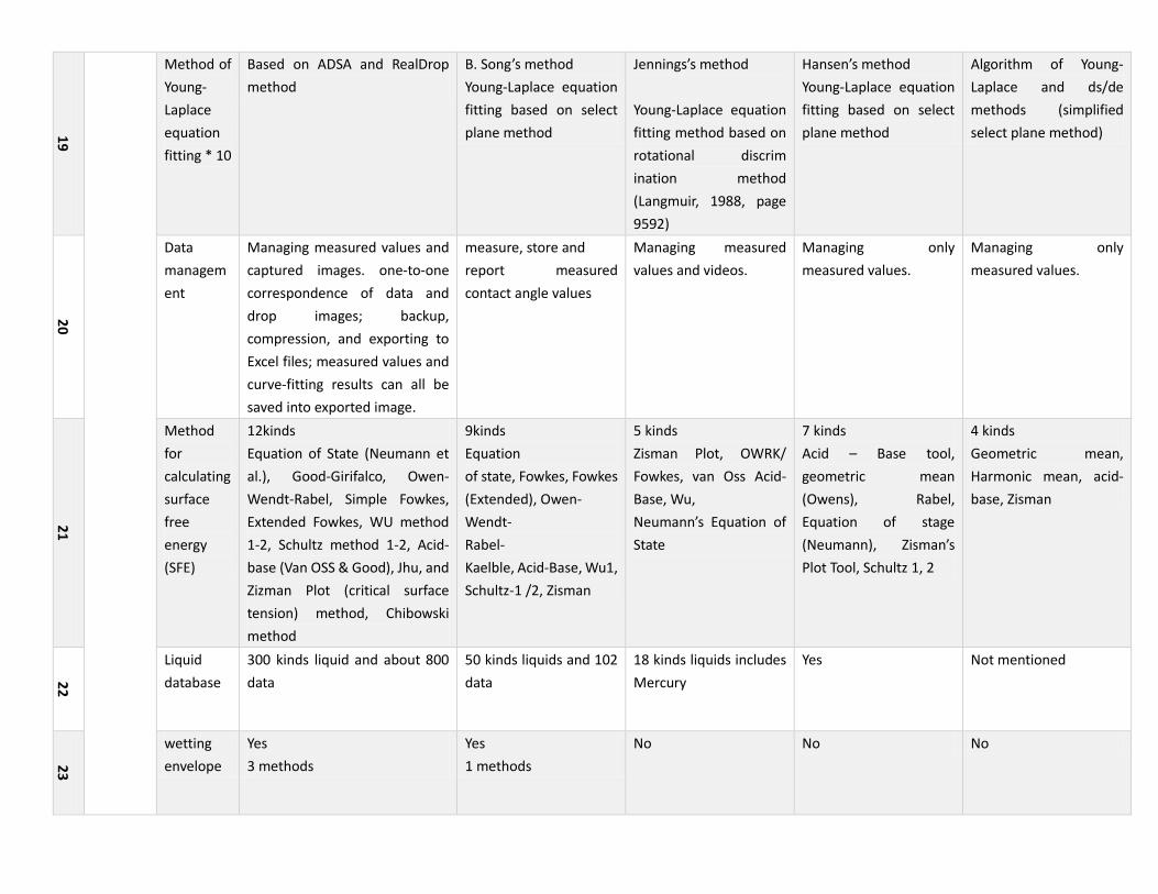
19
Method of
Young-
Laplace
equation
fitting * 10
Based on ADSA and RealDrop
method
B. Song’s method
Young-Laplace equation
fitting based on select
plane method
Jennings’s method
Young-Laplace equation
fitting method based on
rotational discrim
ination method
(Langmuir, 1988, page
9592)
Hansen’s method
Young-Laplace equation
fitting based on select
plane method
Algorithm of Young-
Laplace and ds/de
methods (simplified
select plane method)
20
Data
managem
ent
Managing measured values and
captured images. one-to-one
correspondence of data and
drop images; backup,
compression, and exporting to
Excel files; measured values and
curve-fitting results can all be
saved into exported image.
measure, store and
report measured
contact angle values
Managing measured
values and videos.
Managing only
measured values.
Managing only
measured values.
21
Method
for
calculating
surface
free
energy
(SFE)
12kinds
Equation of State (Neumann et
al.), Good-Girifalco, Owen-
Wendt-Rabel, Simple Fowkes,
Extended Fowkes, WU method
1-2, Schultz method 1-2, Acid-
base (Van OSS & Good), Jhu, and
Zizman Plot (critical surface
tension) method, Chibowski
method
9kinds
Equation
of state, Fowkes, Fowkes
(Extended), Owen-
Wendt-
Rabel-
Kaelble, Acid-Base, Wu1,
Schultz-1 /2, Zisman
5 kinds
Zisman Plot, OWRK/
Fowkes, van Oss Acid-
Base, Wu,
Neumann’s Equation of
State
7 kinds
Acid – Base tool,
geometric mean
(Owens), Rabel,
Equation of stage
(Neumann), Zisman’s
Plot Tool, Schultz 1, 2
4 kinds
Geometric mean,
Harmonic mean, acid-
base, Zisman
22
Liquid
database
300 kinds liquid and about 800
data
50 kinds liquids and 102
data
18 kinds liquids includes
Mercury
Yes Not mentioned
23
wetting
envelope
Yes
3 methods
Yes
1 methods
No No No
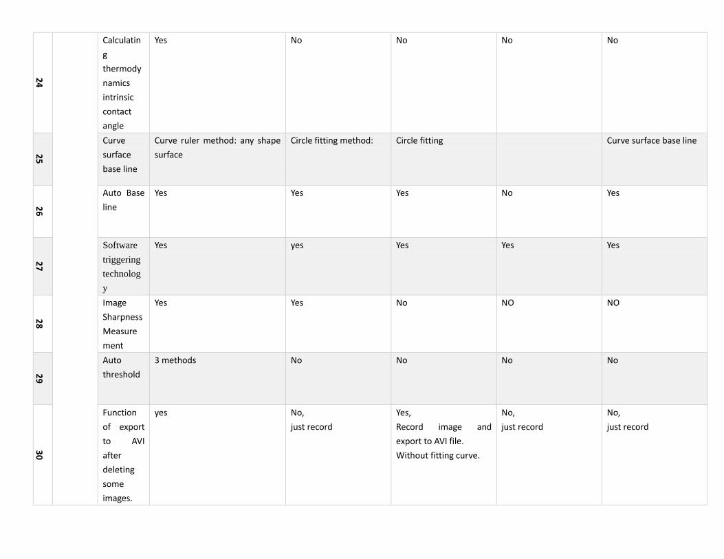
24
Calculatin
g
thermody
namics
intrinsic
contact
angle
Yes No No No No
25
Curve
surface
base line
Curve ruler method: any shape
surface
Circle fitting method: Circle fitting Curve surface base line
26
Auto Base
line
Yes Yes Yes No Yes
27
Software
triggering
technolog
y
Yes yes Yes Yes Yes
28
Image
Sharpness
Measure
ment
Yes Yes
No NO NO
29
Auto
threshold
3 methods No No No No
30
Function
of export
to AVI
after
deleting
some
images.
yes No,
just record
Yes,
Record image and
export to AVI file.
Without fitting curve.
No,
just record
No,
just record
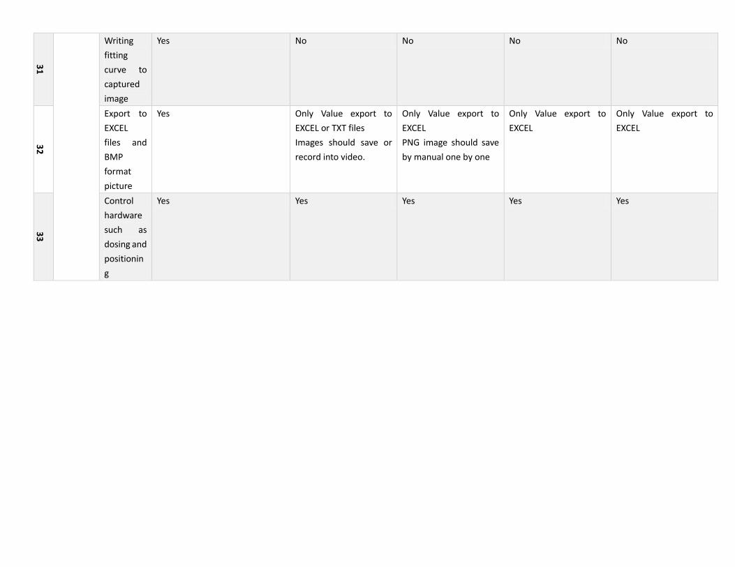
31
Writing
fitting
curve to
captured
image
Yes No No No No
32
Export to
EXCEL
files and
BMP
format
picture
Yes Only Value export to
EXCEL or TXT files
Images should save or
record into video.
Only Value export to
EXCEL
PNG image should save
by manual one by one
Only Value export to
EXCEL
Only Value export to
EXCEL
33
Control
hardware
such as
dosing and
positionin
g
Yes Yes Yes Yes Yes

Note:
1, 2, 3 Control of sample stage along XY axis is used for measuring contact angle of different position on sample surface. And, control of sample stage along Z axis is used
for measuring sample with different thickness. KINO is only manufactory of contact angle meter that adopts motorized linear stage or manual positioner for motion control
system. By comparison, contact angle meter made by other factory always uses common adjustment mechanism such as “dovetail stage” or just one optical bench with
holder unit and height adjustable rod stand. (Note: these is always used for quick and long travel range adjustment that need no accuracy.)
For more information of them, visit https://www.newport.com/Products/5465115/1033/nav.aspx or http://www.sigma-koki.com. KINO’s contact angle meter adopts such
motion control system as this manufactory’s and accords with its design accuracy. You can find difference such as load capacity and travel accuracy between rack and pinion
dovetail stage, translating optical post holder and crossed-roller guide positioner with micrometer. It is shown that crossed-roller guide positioner with micrometer is most
suitable for vertical position. Motorized linear stage controlled by software with slide guide provide more stable and smooth movement and positioning of drop.
4, Level adjustment of sample stage except adjusting complete machine by four adjustable legs is most important. For example, after you adjusted levelness of sample
stage at first, when you measure sample with poor level surface, it is more difficult to get good base line and obtain two contact points. As shown below:
5, Tilting system for measurement of roll-off angle of KINO’s contact angle meter adopts motorized rotation stage with very low backlash, low wobble (about 40urad) and
high absolute accuracy (about 0.01°) . KINO exclusively provides you specially designed mechanical Structure (Rotating only Lens, sample stage and its control system)
instead of rotating complete machine. Accuracy and backlash of latter is very poor due to control complete machine is very difficultly.
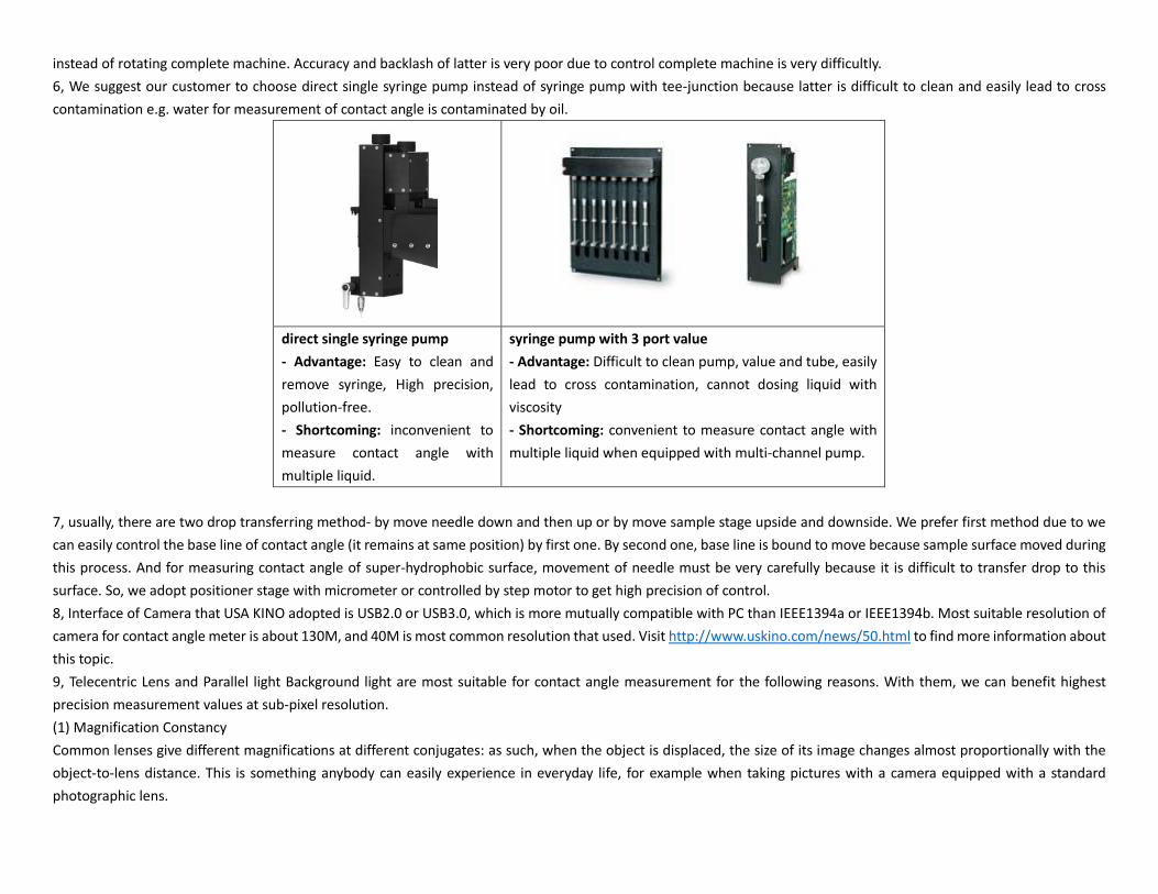
6, We suggest our customer to choose direct single syringe pump instead of syringe pump with tee-junction because latter is difficult to clean and easily lead to cross
contamination e.g. water for measurement of contact angle is contaminated by oil.
direct single syringe pump
- Advantage: Easy to clean and
remove syringe, High precision,
pollution-free.
- Shortcoming: inconvenient to
measure contact angle with
multiple liquid.
syringe pump with 3 port value
- Advantage: Difficult to clean pump, value and tube, easily
lead to cross contamination, cannot dosing liquid with
viscosity
- Shortcoming: convenient to measure contact angle with
multiple liquid when equipped with multi-channel pump.
7, usually, there are two drop transferring method- by move needle down and then up or by move sample stage upside and downside. We prefer first method due to we
can easily control the base line of contact angle (it remains at same position) by first one. By second one, base line is bound to move because sample surface moved during
this process. And for measuring contact angle of super-hydrophobic surface, movement of needle must be very carefully because it is difficult to transfer drop to this
surface. So, we adopt positioner stage with micrometer or controlled by step motor to get high precision of control.
8, Interface of Camera that USA KINO adopted is USB2.0 or USB3.0, which is more mutually compatible with PC than IEEE1394a or IEEE1394b. Most suitable resolution of
camera for contact angle meter is about 130M, and 40M is most common resolution that used. Visit http://www.uskino.com/news/50.html to find more information about
this topic.
9, Telecentric Lens and Parallel light Background light are most suitable for contact angle measurement for the following reasons. With them, we can benefit highest
precision measurement values at sub-pixel resolution.
(1) Magnification Constancy
Common lenses give different magnifications at different conjugates: as such, when the object is displaced, the size of its image changes almost proportionally with the
object-to-lens distance. This is something anybody can easily experience in everyday life, for example when taking pictures with a camera equipped with a standard
photographic lens.

Fig. 1: a standard lens generates different size images when changing the object-to-lens distance (indicated as ”s” in the drawing). On the other hand, objects of different
sizes would look as if they had the same dimensions, provided they subtend the same viewing angle.
With telecentric lenses the image size is left unchanged with object displacement, provided the objectstays within a certain range often referred to as “depth of field” or
“telecentric range”. This is due to the particular path of the rays within the optical system: only ray cones whose barycentric ray (or “principal ray”) is parallel to the opto-
mechanical main axis are collected by the objective. For this reason, the front lens diameter must be at least as large as the object field diagonal. This optical behaviour is
obtained by positioning the stop aperture exactly on the focal plane of the front optical group: the incoming rays aim at the entrance pupil which appears as being
virtually placed at the infinity. The name “telecentric” derives from the words “tele” (which means “far” in ancient Greek) and “centre” which accounts for the pupil
aperture, the actual centre of an optical system.
Fig. 2: in a telecentric system rays get into the optics only with an almost parallel-to-the-axis path.
(2) Low Distortion
Distortion is one of the worst problems limiting measurement accuracy: even the best performing optics are affected by some grade of distortion, while often even a single
pixel of difference between the real image and the expected image could be critical.
Distortion is simply defined as the percentage difference between the distance of an image point from the image center and the same distance as it would be measured
in a distortion-free image; it can be thought of as a deviation between the imaged and the real dimensions of an object. For instance, if a point of an image is 198 pixels
distant from the center, while a distance of 200 pixels would be expected in absence of distortion, the radial distortion, at that point, would be
Distortion = (198-200)/200 = -2/200 = 1%

Fig.3: “pincushion” type distortion “barrel” type distortion
Positive radial distortion is also called “pincushion” distortion, negative radial distortion is called “barrel” distortion: note that the distortion depends on the radial
position and can also change of sign. Distortion can be also viewed as a 2D geometrical transformation of the real world into the virtual space created by the
lens; as this transformation is not perfectly linear but is approaching 2nd or 3rd degree polynomials, the image becomes slightly stretched and deformed.
Common optics show distortion values ranging from some percent to some tens percent, making precise measurement really difficult; things get even worse when non-
telecentric lenses are used. Since most machine vision optics have originally been developed for video-surveillance or photography applications, relevant distortion values
have usually been considered acceptable, as the human eye can compensate distortion errors up to 1-2%. In some cases, like in fish-eye lenses or webcam-style lenses,
distortion is intentionally introduced to make the lens work on large angles also providing an even illumination of the detector (in these cases distortion is helpful in
reducing cosine-to-the-fourth law effects).
High quality telecentric lenses normally show a very low distortion degree, in the range of 0,1%; although this amount seems to be very small it would actually result into
measurement errors approaching the size of one pixel of an high resolution camera. For this reason, in most applications, distortion has to be software calibrated: a precise
pattern (whose geometrical accuracy must be at least ten times better than the needed measurement accuracy) is placed at the center of the field depth; distortion is
then computed at several image points and, based on these data, the software algorithm transforms the native image into a distortion-free image. Few people know that
the distortion also depends upon the distance of the object, not only upon the optics itself; for this reason it is very important
Few people know that the distortion also depends upon the distance of the object, not only upon the optics itself; for this reason it is very important that the nominal
working distance is strictly respected.
A fine perpendicular alignment between the lens and the inspected object is recommended in order to avoid non-axially symmetric distortion effects. Trapezoidal distortion
(also known as “keystone” or “thin prism” effect) is another important parameter to be minimized in an optical inspection system as it is asymmetric and very difficult to
software calibrate. Lens focusing mechanism can also introduce some symmetric or non-symmetric distortion effect because of mechanical play or optical element
decentering.

Fig. 4: on the left an image of a distortion pattern taken with a telecentric lens, where no radial or trapezoidal distortion is present. In the middle the image of the same
pattern showing strong radial distortion. On the right an example of trapezoidal distortion.
(3) Perspective Errors limitation
When using common optics to image 3D objects (non completely flat objects) far objects will look smaller than close objects. As a consequence, when objects like a
cylindrical cavity are imaged, the top and the bottom crown edges will appear to be concentric although the two circles are perfectly identical.
On the contrary, by means of a telecentric lens, the bottom crown edge will disappear because the two crown edges are perfectly overlapping.
Fig. 5: Common optics showing significant image perspective error (on the left). A telecentric lens is able to cancel any perspective effect (on the right).
This effect is due to the specific path of the rays: in the case of common optics, any geometric information that is “parallel” to the main optical axis also shows a component
on the detector plane direction, while in a telecentric lens this perpendicular component is totally absent.
One could describe a common lens as a mathematical function building a correspondence between the 3-dimensional object space and the 2-dimensional detector
(image) space while a telecentric would build a 2D-2D correspondance as would not display an object’s third dimension thus making it the perfect component for profile
imaging and measurement.

Fig. 6: Common optics (left) project longitudinal geometrical information onto the detector, while telecentric lenses are not.
(4) Good image resolution
Image resolution is decribed by CTF (contrast transfer function) which quantifies the contrast ratio at a given spatial frequency on the camera detector plane, expressed in
lp/mm (line pairs per millimeter).
Fig. 7: good and bad contrast achieved with optics of varying CTF looking at a standard USAF test pattern.
Quite often, machine vision integrators tend to combine cameras having tons of small pixels with cheap, poor resolution lenses, resulting in blurred images; the resolution
provided by telecentric lenses is compatible with very small pixel sizes and high resolution cameras thus increasing the measurement resolution.
(5) No edge position uncertainty
When common back lighting an object it can often be difficult to determine the exact position of its edges.
This can happen because the bright pixels in the background tend to overlap with the dark pixels at the object edges. Moreover, if the object is highly 3D-shaped, also a
border effect could furtherly limit the measurement precision; as shown in the following drawing, rays grazing the object edges at certain incidence angles could be
reflected by the surface, but still be collected by the lens.
The lens would then see those rays as if they were coming from behind the object; as a result, slices of the image could disappear, thus making the measurement very
much imprecise and unstable.

Fig. 8: Border effects in a common imaging lens are strongly reduced by means of a telecentric lens
This effect can be efficiently limited by means of a telecentric lens: if the pupil aperture is small enough, the only reflected rays which could enter the lens would be those
nearly parallel to the optical main axis.
As these rays are affected by very small deflection, the reflection from the object surface doesn’t jeopardize the measurement accuracy.
To get rid of such issues, Parallel light Background light (also called “collimated” or “telecentric”) illuminators can be interfaced to telecentric lenses, taking care of
matching the lens aperture and FOV with the collimated source divergence. With this option, all the light coming out of the illuminator is collected by the lens and delivered
onto the detector, allowing extremely high signal-to-noise ratios and incredibly low exposure times. On the other hand, only “expected” rays come into the imaging lens
so that no problems occur at the borders.
Fig. 9: Parallel light Background light (Collimated light, telecentric) illumination projects only the expected rays into the imaging system.
We captured some images use using 2 different combinations of lens and background (one is common lens and diffused background light as used in general contact angle
measurement instrument, another is used telecentric lens and Parallel light Background light)

Fig. 10: Image of pendant drop used Parallel light Background light and telecentric lens. We can find little change range
of sharpness at image edge when zooming it about 1500X.
Fig. 11: Image of pendant drop used common Background light and lens. We can find more change range of
sharpness at image edge when zooming it about 1500X.

Fig. 12: Image of sessile drop with little change range of sharpness used Parallel light Background light and telecentric lens.
Fig. 13: Image of sessile drop with more change range of sharpness used common Background light and lens.

(5) Not disturbed by flare veiling glare
Flare veiling glare cannot disturb image capture process.