Ford Super Duty 4x4 Mag Hytec Rear Diff Cover Install Rear Diff
Upload
sudhir-sainiCategory
view
53download
1
IS: 3842(PartX)-1976
Indian Standard APPLICATION GUIDE FOR
ELECTRICAL RELAYS FOR AC SYSTEMS
PART X RELAYS FOR TRANSVERSE DIFFERENTIAL PROTECTION
( Third Reprint OCTOBER 1992 )
UTX 621.316.925.2
@ Coplright 1976
BUREA? OF INDIAN STANDARDS MANAK BHAVAN, 9 BAHADUR SHAH ZWAK MARG
NEWDELHIllMXY2
Doceder 1976
c
.
IS : 3842 ( Part X ) - 1976
Indian Standard APPLICATION GUIDE FOR
ELECTRI~AL~RELAY~ FOR AC SYSTEMS PART X RELAYS FOR TRANSVERSE DIFFERENTIAL
PROTECTION
Relays Sectional Committee, ETDC 35
Chairman
DR T. S. M. RAO
Members
Representing
University of Roorkee, Roorkee
&RI N. S. S. AROKIASWAMY Tamil Nadu Electricity Board, Madras SHRI T. V. SUBRAMANIAM ( Alternatr ) \
SHRI M. M. BANDRE Maharashtra State Electricity Board, Bombay SHRI G. R. BHATIA Directorate General of Supplies and Disposals
( Inspection Wing), New Delhi Railway Board, New Delhi DEPUTY DIRECTOR STANDARDS
( TI ), RDSO, LUCKNOW ASSISTANT DIRECTOR STAND-
ARDS ( RELAYS ). ( Alternate ) DIRECTOR ( CIP ) SHRI A. K. GHOSE
SHRI C. GHOSE ( Alternate ) SHRI B. P. GHOSH SHRI S. GOVINDAPPA SHRI B. R. GUPTA
SHRIJ. C. JUNE~A ( Alternate) SHRI I. C. JOSEPH SHRI A. D. LIMAY~
Central Electricity Authority, New Delhi Universal Electrics Limited, 24 Parganas
National Test House, Calcutta Karnataka Electricity Board, Bangalore Haryana State Electricity Board, Chandigarh
Larsen & Toubro Limited, Bombay Bombay Electric Supply & Transport Undertaking,
SHRI A. M. KELKAR ( Alterna/e) SHR~ MATA PRASAD SHRI N. NATH SIIRI J. S. NECI
SHRI V. B. DESAI ( Alternate ) SHRI S. T. PATEL
SHRI V. RAGHUPATI ( Alternate ) SHR~ V. RADHAKRISHNAN
Bombay
U.P. State Electricity Board, Lucknow English Electric Co of IndiaLtd, Madras Jyoti Limited, Vadodara
ASEA Electric India Pvt Ltd, Bombay
Bharat Heavy Electricals Ltd, Bhopal . SHRI M. R. NANDESHWAR ( Alternate )
( Continued on page 2 )
@ Copvright 1976
BUREAU OF INDLW STANDARDS This publication is protected under the Indian Copyright Act (XIV of 1957) and reproduction in whole or in part by any means except with written permission of the publisher shall be deemed to be an infringement of copyright under the said Act.
IS : 3842 ( Part X ) - 1976
( Continued from page 1 )
Members Reprtscnting
SHRI K. N. RAMASWAMY Directt:;te General of Technical Development, New
SHRI R. K. GUPTA (Ahnate ) SHBJ P. RANGASWA~XY Hindustan Steel Ltd, Ranchi
SHRI T. C. RAJAGOPALAN ( Alfernatc ) DR B. RAMESH RAO Tata Merlin & Gcrin Ltd, Bombay
SHRI C. P. RAMA RAO ( Alternate ) SHRI U. V. RAO Hindustan Brown Boveri Ltd, Bombay
SHRI V. BALAXIBRAMANIAN ( Ahnate ) SHRI A. M. SAW-41 Tata Hydra-Electric Power Supply Co Ltd, Bombay
SHXI V. S. DORAI ( Alfcrnatc) DR Y. V. SOW.YAJULU National Physioal Laboratory ( CSIR ), New Delhi
SHRI P. SURAYANARAYANA ( Alternate ) SHRI G. N. THADANI Engineers India Limited, New Delhi
SHRI H. K. KAUL ( Altern& ) SHRI S. P. SACHlXV, Director General, IS1 ( Ex-O#&I Member )
Director ( Elec tech )
Scnetaty
SHKI VIJAI Deputy Director ( Elec tech ), IS1
2
16 : 3842 ( Part X ) - 1976
Indian Standard APPLICATION GUIDE FOR
ELECTRICAL RELAYS FOR AC SYSTEMS
PART X RELAYS FOR TRANSVERSE DIFFERENTIAL PROTECTION
0. F-OREWORD
0.1 This Indian Standard ( Part X ) was adopted by the Indian Standards Institution on 27 July 1976, after the draft finalized by the Relays Sectional Committee had been approved by the Electrotechnical Division Council.
0.2 Modern power systems are designed to provide uninterrupted electrical supply, yet the possibility of failure cannot be ruled out. The protective relays stand watch and in the event of failures, short circuits or abnormal operating conditions help de-energise the unhealthy section of the power system and restrain interference with the remainder of it and thus limit damage to equipment and ensure safoty of personnel. They are also used to indicate the type and location of failure so as to assess the effectiveness of the protective schemes.
0.3 The features which the protective relays should possess are the following:
a) Reliability, that is, to ensure correct action even after long periods of inactivity and also to offer repeated operation under severe conditions;
b) Selectivity, that is, to ensure that only the unhealthy part of the system is disconnected;
c) Sensitivity, that is, detection of short-circuit or abnormal operat- ing conditions;
d) Speed to prevent and minimise damage and risk of instability of rotating plant; and
e) Stability, that is, ditions that call
the ability to operate only under those con- for its operation and to remain either passive or
~biased against operation under all other conditions.
0.4 Transverse differential protection system falls in the clas$ of unit protection and is generally applied for circuits of a parallel group. This protection system compares the currents at the same ends of two or more
3
IS : 3842 ( Part X ) - 1976
parallel circuits and relies on the principle that load and throughfault current divide equally between the circuits of a parallel group and any difference is au indication of an internal fault.
0.4.1 Transvcrsc dilrcrcncjal protection is extensively used for parallel feeder protection on I’ccdcrs of moderate length, even up to 132 kV, where economic and/or physic;11 factors preclude the application of pilot wire, power line carrier or distance schemes. This protection system is also some times applied for interturn fault ‘protection of large alternator sets provided with two windings per phase.
0.4.2 Lo@tudinal differential schemes applied to single circuit in which the comparison of currents is at the opposite ends of the same circ’uit are not covcrcd by this application guide.
0.5 It is emphasized that this guide has been prepare4 to assist in appli- cation rather than to specify the relay to be used. This guide deals only with the general principles of scheme5 and does not deal with the selection of any particular scheme. The actual circuit conditions perhaps may be dilTercnt from those given in this guide.
0.6 In the preparation of this guide, considerable assistance has been derived from several published books and technical papers and from manu- facturers’ trade literature.
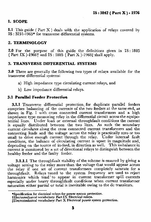
0.7 This guide, is one of the series of application guides for electrical relays’ f’or ac systems. The other guides in this series are the following:
IS : 3638-1966 Application guide for gas-operated relays
IS : 384‘2 ( Part I )-1967 Application guide for electrical relays for ac systems: Part I Overcurrent relays for feeders and transformers
IS : 3842 ( Part II )-1966 Application guide fdr electrical relays for ac systems: Part II Overcurrent relays for generators and motors
IS : 3842 ( Part III )-1966 Application guide for electrical relays for ac systems: Part II! Phase unbalance relays including negative phase sequence relay&
IS : 3842 ( Part IV )-lo66 Application guide for electrical relays for ac systems: Part IV Thermal relays
IS : 3842 ( Part V )-1968 Application guide for electrical relays for ac systems: Part V Distance protection relays
IS : 3842 ( Part VI )-1972 Application guide for electCca1 relays for ac systems: Part VI Power relays
IS : 3842 ( Part VII )-1972 Application guide for electrical relays for ac systems: Part VII Frequency relays
IS : 3842 ( Part XII )-1976 Application guide for electrical relays for ac systems: Part XII Differential relays for transformers
4
IS : 3842 ( Part X) - 1976
1. SCOPE
1.1 This guide ( Part X ) deals with the application of relays covered by IS : 3231-1965* for transverse differential systems.
2. TERMINOLOGY
2;O For the purpose of this guide the definitions given in IS : 1885 ( Part IX )-1966t and IS : 1885 ( Part X )-1968$ shall apply.
3. TRANSVERSE DIFFERENTIAL SYSTEMS
3.0 There are generally the following two types of relays available for the transverse differential systems:
a) High impedance type circulating current’relays, and
b) Low impedance differential relays.
3.1 Parallel %eeder Protection
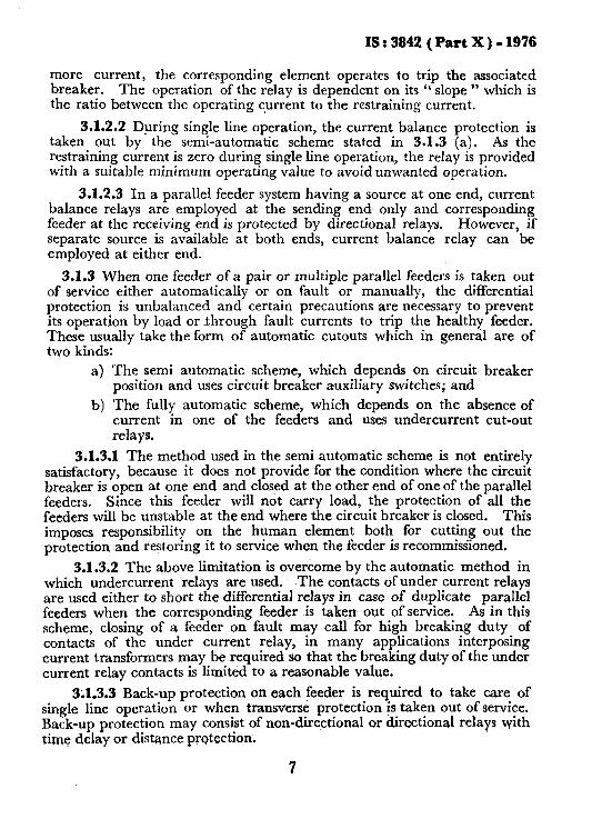
3.1.1 Transverse differential protection. for duplicate parallel feeders comprises balancing of the currents of the two feeders at the same end, as shown in Fig. 1 with cross connected current transformers and a high impedance type measuring relay in the differential circuit across the equipo- tential lines. Under load or external throughfault conditions the current is equally distributed between the two lines. As such the secondary current circulates along the cross connected current transformers and the connecting leads and the voltage across the relay is practically zero or too small to drive enough current through the relay. Under internal fault conditions, the balance of circulating current is upset in magnitude and, depending on the source of in-feed, in direction as well. This unbalance in current is monitored by a set of directional relays to distinguish between the healthy feeder and the faulty feeder.
3.1.1.1 The throughfault stability of the scheme is ensured by giving a voltage setting to the relay more than the voltage that would appear across the relay if one set of current transformers completely saturate for a throughfault. Relays tuned to the system frequency are used to reject harmonics which tend ’ to appear in current transformer spill currents especially under heavy throughfault conditions when current transformer saturation either partial or total is inevitable owing to the dc transients.
*Specification for electrical relays for power system protection. tElectrotechnica1 vocabulary: Part IX Electrical relays. $‘&@rpteQnical vocsbulary: Part X Electrical power system protection,
5
IS : 3842 ( Part X ) - 1976
,yUNGER CURRENT RELAYS /
I CURRENT i TRANSFORMER .
~DIRECTIONAL RELAYS
i
NORMALLY OPEN CONTACT \ b
z- _ -” .-.. .-
t IAtJILILING r
CLOSED- CONTACT 1 1
FIG. 1 TYPICAL HIGH IMPEDANCE SCHEME FOR DUPLICATE PARALLEL FEEDERS
3.1.2 Current balance relay is at times used for fast protection of duplicate parallel feeders. The current balance relay compares the current between the two feeders and when there is an abnormal change in the division of current between the two circuits, which happens during a fault in a feeder, the relay operates to trip the breaker associated with the faulty line.
3.1.2.1 Such a relay has two operating elements actuated by currents obtained from the two circuits. One element receives operating current from one of the feeders and restraining current from the other. Vice-versa is the case for the other element. Depending on which of the feeders has
6
c
IS : 3842 ( Part X ) - 1976
more current, the corresponding element operates to trip the associated breaker. The operation of the relay is dependent on its “ slope ” which is the ratio between the operating current to the restraining current.
3.1.2.2 During single line operation, the current balance protection is taken out by the semi-automatic scheme stated in 3.1.3 (a). As the restraining current is zero during single line operation, the relay is provided with a suitable minimum operating value to avoid unwanted operation.
3.1.2.3 In a parallel feeder system having a source at one end, current balance relays are employed at the sending end only and corresponding feeder at the receiving end is protected by directional relays. However, if separate source is available at both ends, current balance relay can be employed at either end.
3.1.3 When one feeder of a pair or multiple parallel feeders is taken out of service either automatically or on fault or manually, the differential protection is unbalanced and certain precautions are necessary to prevent its operation by load or through fault currents to trip the healthy feeder. These usually take the form of automatic cutouts which in general are of two kinds:
a) The semi automatic scheme, which depends on circuit breaker position and uses circuit breaker auxiliary switches; and
b) The fully automatic scheme, which depends on the absence of current in one of the feeders and uses undercurrent cut-out relays.
3.1.3.1 The method used in the semi automatic scheme is not entirely satisfactory, because it does not provide for the condition where the circuit breaker is open at one end and closed at the other end of one of the parallel feeders. Since this feeder will not carry load, the protection of all the feeders will be unstable at the end where the circuit breaker is closed. This imposes responsibility on the human element both for cutting out the protection and restoring it to service when the feeder is recommissioned.
3.1.3.2 The above limitation is overcome by the automatic method in which undercurrent relays are used. The contacts of under current relays are used either to short the differential relays in case of duplicate parallel feeders when the corresponding feeder is taken out of service. As in this scheme, closing of a feeder on fault may call for high breaking duty of contacts of the under current relay, in many applications interposing current transformers may be required so that the breaking duty of the under current relay contacts is limited to a reasonable value.
3.1.3.3 Back-up protection on each feeder is required to take care of single line operation or when transverse protection is taken out of service. Back-up protection may consist of non-directional or directional relays with time delay or distance protection.
7
IS : 3842 ( Part X ) - 1976
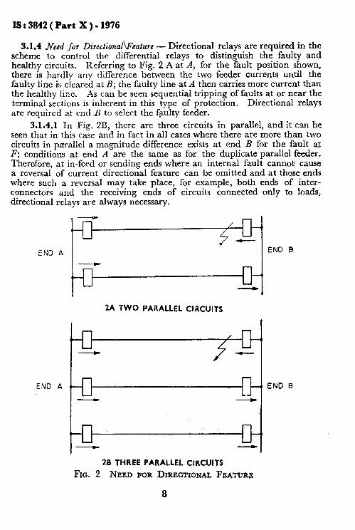
3.1.4 Need ,for Directional\Fcature - Directional relays are required in the scheme to control the differential relays to distinguish the faulty and healthy circuits. Referring to Fig. 2 A at A, for the fault position shown,
’ there is hardly any difference between the two feeder currents until the faulty line is cleared at B; the faulty line at A then carries more current than the healthy line. As can be seen sequential tripping of faults at or near the terminal sections is inherent in this type of protection. Directional relays are required at end B to select the faulty feeder.
3.1.4.1 In Fig. 2B, there are three circuits in parallel, and it can be seen that in this case and in fact in all cases where there are more than two circuits in parallel a magnitude difference exists at end B for the fault at F; conditions at end A are the same as for the duplicate parallel feeder. Therefore, at in-feed or sending ends where an internal fault cannot cause a reversal of current directional feature can be omitted and at those ends where such a reversal may take place, for example, both ends of inter- connectors and the receiving ends of circuits connected only to loads, directional relays are always necessary.
END A
%
2A TWO PARALLEL CIRCUITS
END A
26 THREE PARALLEL CIRCUITS
FIG. 2 NEED FOR DIRECTIONU FBATUIU
END B
END B
18 : 3b42 ( Part X ) - 1976
3.2 Transverse Differential Protection of -Synchronous Machines
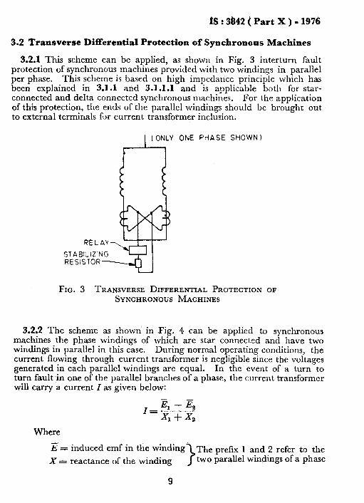
3.2.1 This scheme can be applied, as shown in Fig. 3 interturn fault protection of synchronous machines provided with two windings in parallel per phase. This scheme is based on high impedance principle which has been explained in 3.1.1 and 3.1.1.1 and is applicable both for star- connected and delta connected synchronous machines. For the application of this protection, the ends of the parallel windings should be brought out to external terminals for current transformer inclusion,
1 ( ONLY ONE PHASE SHOWN I
RELAY
STABILIZING RESISTOR-
FIG. 3 TRANSVERSE DIFFERENTIAL PROTECTION OF SYNCHRONT)US MACHINES
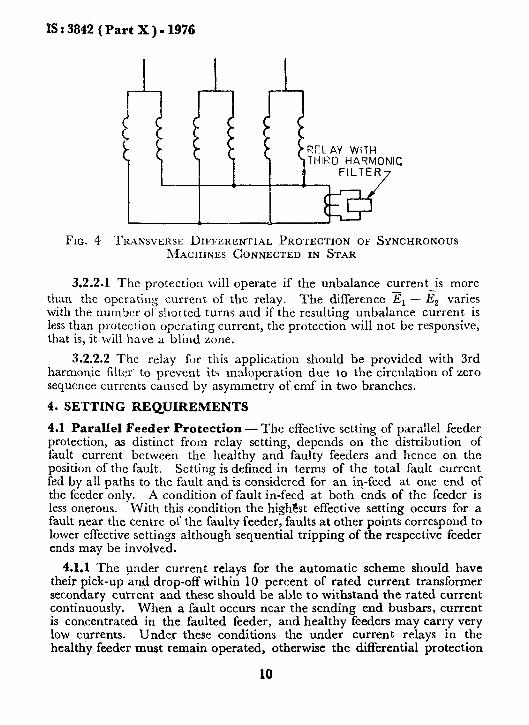
3.2.2 The scheme as shown’ in Fig. 4 can be applied to synchronous machines the phase windings of which arc star connected and have two -windings in parallel in this case. During normal operating conditions, the current flowing through current transformer is negligible since the voltages generated in each parallel windings are equal. In the event of a turn to turn fault in one of the parallel branches of a phase, the current transformer will carry a current I as given below:
Where 7 h = induced emf in the winding The prefix 1 and 2 refer to the
x= reactance of the winding two parallel windings of a phase
9
IS : 3842 ( Part X ) - 1976
FIG. 4 TRANSVERSE I)IFFEKENTIAL PROTECTION OF SYNCHRONOUS MACHINES CONNECTED IN STAR
3.2.2.1 The protection will operate if the unbalance current is more than the operating current of the relay. The difference Er - I$ varies with the number ol‘sl~ortcd turns and if the resulting unbalance current is less than protection opcratin g current, t!le protection will not be responsive, that is, it will have a blind zone.
3.2.2.2 The relay for this application should be provided with 3rd harmonic filter. to prevent its maloperation due to the circulation of zero sequence currents caused by asymmetry of emf in two branches.
4. SETTING REQUIREMENTS
4.1 Parallel Feeder Protection - The effective setting of parallel feeder protection, as distinct from relay setting, depends on the distribution of fault current between the healthy and faulty feeders and hence on the position of the fault. Setting is defined in terms of the total fault current fed by all paths to the fault and is considered for an iq-feed at one end of the feeder only. A condition of fault in-feed at both ends of the feeder is less onerous. With this condition the high&t effective setting occurs for a fault near the centre of the faulty feeder, faults at other points correspond to lower effective settings although sequential tripping of the respective feeder ends may be involved.
4.1.1 The under current relays for the automatic scheme should have their pick-up and drop-off within 10 percent of rated current transformer secondary cutrent and these should be able to withstand the rated current continuously. When a fault occurs near the sending end busbars, current is concentrated in the faulted feeder, and healthy feeders may carry very low currents. Under these conditions the under current relays in the healthy feeder must remain operated, otherwise the differential protection
10
IS : 3842 ( Part X ) - 1976
may be switched out of service. Although the operating current may be as low as possible, the reset current should be greater than the feeder charg- ing current to prevent the relay remaining operated w’hen the circuit- breaker at far end opens. A sensitive relay is therefore required for this application specially for the sending end. At the receiving end the require- ments are less onerous since either load or fault current flows in both or all feeders while they are in service. The operating value of the relay should be equivalent to the setting of parallel feeder protection, and the relay should reset just above the value of charging current.
4.2 Transverse Differential Protection of Synchronous Machines - The method of calculating the stabilising resistor in series with the r#ay for high impedance protection and relay voltage setting for transverse differ- ential protection of parallel feeders is given in Appendix A.
APPENDIX A
( Clause 4.2 )
CALCULATION OF RELAY VOLTAGE SETTING AND VALUE OF STABILIZING RESISTOR
A-l. CALCULATION OF RELAY VOLTAGE SETTING AND VALUE OF STABILIZING RESISTOR FOR A TYPICAL HIGH IMPEDANCE SCHEME
A-l.1 Consider a generator. rated at 125 MVA, 11 kV and having two windings per phase. The sub-transient reactance of the generator is 20 percent.
Full load current of the generator = J 3 Ff l”,‘~~s = 6 600 A
Therefore, maximum throughfault current from the machine
6 600 =--33000A
0.2
Let the protective current transformer to which the high impedance relay is connected have a ratio of 4 00015.
Current transformer equivalent of 33 000 maximum throughfault current ( 4 ) = --2--- x & =20*62A
11
IS : 3842 ( Part X ) - 1976
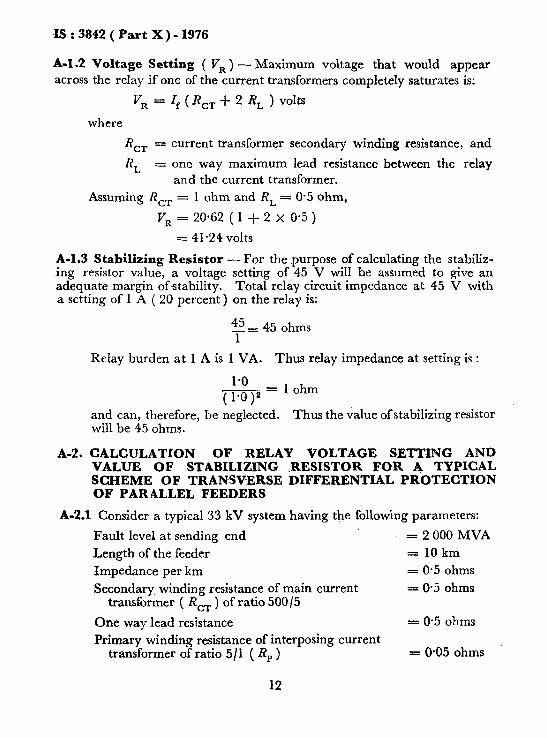
A-1.2 Voltage Setting ( VR ) - Maximum voltage that would appear across the relay if one of the current transformers completely saturates is:
v, = where
R CT =
R, =
If ( R,, + 2 R, ) volts
current transformer secondary winding resistance, and
one way maximum lead resistance between the relay and the current transformer.
Assuming R,, = 1 ohm and R, = 0.5 ohm,
VR = 20.62 ( 1 + 2 x OS5 )
= 41.24 volts
A-l.3 Stabilizing Resistor - For the purpose of calculating the stabiliz- ing resistor value, a voltage setting of 45 V will be assumed to give an adequate margin of stability. Total relay circuit impedance at 45 V with a setting of 1 A ( 20 percent) on the relay is:
45 _= 45 ohms 1
Relay burden at 1 A is 1 VA. Thus relay impedance at setting is :
( :*:,2 = 1 ohm
and can, therefore, be neglected. Thus the value of stabilizing resistor will be 45 ohms.
A-2. CALCULATION OF RELAY VOLTAGE SETTING AND VALUE OF STABILIZING .RESISTOR FOR A TYPICAL SCHEME OF TRANSVERSE DIFFERENTIAL PROTECTION OF PARALLEL FEEDERS
A-2S Consider a typical 33 kV system having the following parameters:
Fault level at sending end = 2 000 MVA
Length of the feeder = 10km
Impedance per km = 0.5 ohms
Secondary, winding resistance of main current = 0.5 ohms transformer ( R,, ) of ratio 500/5
One way lead resistance = 0.5 ohms
Primary winding resistance of interposing current transformer of ratio 5/l ( Rp ) = 0.05 ohms
12
c
IS : 3842 ( Part X ) - 1976
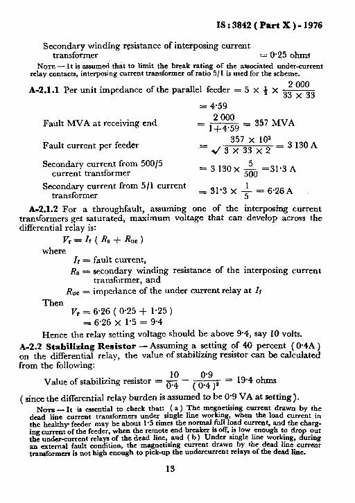
Secondary winding resistance of interposing current transformer = D-25 ohms
NOTE - It is assumed that to limit the break rating of the associated under-current relay contacts, interposing current transformer of ratio 5/l is used for the scheme.
A-2.1.1 Per unit impedance of the parallel feeder = 5 x 4 x &
= 4.59
Fault MVA at receiving end
Fault current per feeder
Secondary current from 50015 current transformer
2 000 =---=357MVA
1+4*59
357 x 10: =43x33x2 =3130A
= 3 130x & =31*3 A
Secondary current from 5/l current transformer
= 31.3 x 1 = 6.26A 5
A-2.1.2 For a throughfault, assuming one of the interposing current transformers get saturated, maximum voltage that can develop across the differential relay is:
Vr = Ir ( RB -i &xc > where
Ii = fault current,
RN = secondary winding resistance of the interposing current transformer, and
RUc = impedance of the under current relay at Zf
Then Vr = 6.26 ( O-25 + 1.25 )
P 6.26 x 1.5 = 9.4
Hence the relay setting voltage should be above 9.4, say 10 volts.
b2.2 Stabilizing Resistor - Assuming a setting of 40 percent ( 0*4A ) on the differential relay, the value of stabilizing resistor can be calculated from the following:
0.9 Value of stabilizing resistor = g - -
(0.4)s = 19.4 ohms
( since the differential relay burden is assumed to be 0.9 VA at setting).
NOTE - It is essetitial to check that: (a ) The megnetising current drawn by the dead lime current transformers under single line working, when the load current in the healthy feeder may be about 1.5 times the normd.full lqad current, and the cbarg- ing current of the feeder, when tpe remote end breaker w off, IS low enough to drop out he under-current relays of the dead line, and ( b) Under single line working, during an external fault condition, the magnetising current drawn by the dead line current transformers is not high enough to pick-up the undercurrent relays of the dead line.
13

BURE.AU OF IINDIAN STANDARDS
Heedquarters :
Manak Bhavan, 9 Bahadur Shah Zafar Marg,NEW DELHI 110002 Telephones : 331 01 31 Telegrams : Manaksanstha
331 13 75 (Common to all Offices)
Region81 Offices :
Central : Manak Bhavan, 9, Bahadur Shah Zafer Marg. NEW DELHI 110002
l Eastern :1/14 C.I.T. Scheme VW M V.I.P. Road, Maniktola. CALCUTTA 700054
Northern : Sk0 445-A6, Sector 35-C, CHANDIGARH 160036 Southern
t Western pus, IV Cross Road, MADRAS 600113
Marot, Andheri (East),
Branch Offices : /
‘Pushpak’, Nurmohamed Shaikh Marg, Khanpur, AHMADABAD 380001 Peenya industrial Area, 1 st Stage, B
$ ngalore-Tumkur Road.
BANGALORE 560058 Gangotri Complex, 5th Ftoor, Bhadbhada Road, T.T. Nagar.
BHOPAL 462303
Plot No. 82183, Lewis doad, BHUBANESHWAR 751b02 Kalai Kathir Building, 6/48-+,Avanasi Road, COIMBATORE 641437 Quality Marking Centre, N.Hd IV1 N.I.T., FARIDABAD 121001 Savitri Cbmplex. 116 G. T. Ro d, 5315 Ward No. 29, R.G. Bar a Road, 5th By-lane, 2
GHAZIABAD 201001
GUWAHATI 781003 6-8-56C L. N. Gupta Marg, ( Nambally Station Road )
HYDERABAD 500001 R14 Yudhister Marg, C Scheme, JAIPUR 302005
llJ/418 B Sarvodaya Nagar, KANPUR 208005
Plot No.,A-9, House No. 561163, Sindhu Nagar. Kanpur Roaa. LUCKNOW 226005
Patliputra Industrial Estate, PATNA 800013
District Industries Centre Complex, Bagh-e-Ali Maidan. SRlNAGAFj 190011
T. C. No. 14/1421, University P. 0.. Palayam, , THlRUVAkANTHAPURAM 695034
f&ection Offices (With Sale Point) : Pushpanjali. First Fior, 205-A West High Coyrt Road.
‘Sbankar Nagar Square, NAGPUR 440010 lnsiitution of Engineers (India) Bbilding, 1332 Shivaii Negar.
\.PUNE 4l-1005
-‘Sales Office Calcutta is at 5 Chdwringhee Approach, P. 0. Princep Street, CALCUTTA
t Sales Office is at Novelty Chambers, Grant R&d, BOMBAY
~A~~;L~~X 1s 8t Unitv Building. ~arasimharaja Square.
Telephbne
i 331 dl 31
333: ;e3 ::
21843 41 29 16
6 32 92 95
26348 39 49 55
55 40 21
5 36 27 2-67 05
8-71.19 96 3 31‘77
231083
6 34 71
21 68 76
5 55 07
62305
6 21 04
52 51 71
5 24 35
27 68 00
89 65 28
22 39 71
Reprography Unit, BIS. New Delhi, India


![SPair-71k: A Large-scale Benchmark for Semantic ...arXiv:1908.10543v1 [cs.CV] 28 Aug 2019 Type View-point diff. Scale diff. Truncation diff. Occlusion diff. easy medi hard easy medi](https://static.fdocuments.in/doc/165x107/6049bbd3adaaa52b560671c6/spair-71k-a-large-scale-benchmark-for-semantic-arxiv190810543v1-cscv-28.jpg)