Diesel engine Series 15D / 18D€¦ · This manual makes safe and efficient use of the engine...
110
Table of contents 2008-07-15 Operator´s manual Diesel engine Series 15D / 18D Dok-ID: Grea-6415 Read the operating instructions before starting work!
Transcript of Diesel engine Series 15D / 18D€¦ · This manual makes safe and efficient use of the engine...
Table of contents
2008-07-15
Operator´s manual
Diesel engine Series 15D / 18D
Dok-ID: Grea-6415 Read the operating instructions before starting work!

2 2008-07-15
© Greaves Farymann Diesel GmbH Industriestraße 19 68623 Lampertheim Germany Tel.: +49 (0) 62 06 / 5 07 - 0 Fax: +49 (0) 62 06 / 5 07 - 111 E-Mail: [email protected] Internet: www.farymann.de
Release:
Created by: Kothes! Technische Kommunikation GmbH & Co. KG www.kothes.de
Diesel engine Series 15D / 18D
Table of contents
2008-07-15 3
1 General....................................................................................6 1.1 Information about this manual .......................................6 1.2 Explanation of the symbols............................................7 1.3 Limitation of liability........................................................8 1.4 Copyright........................................................................9 1.5 Warranty terms ..............................................................9 1.6 Customer service...........................................................9
2 Safety ....................................................................................10 2.1 Customer’s responsibility.............................................10 2.2 Personnel requirements...............................................12
2.2.1 Qualifications................................................12 2.3 Appropriate use ...........................................................13 2.4 Personal protective equipment ....................................14 2.5 Specific dangers ..........................................................15 2.6 Safety devices..............................................................18 2.7 Behaviour in the case of danger and accidents...........18 2.8 Environmental protection .............................................19
3 Technical data ......................................................................20 3.1 Technical specifications...............................................20 3.2 Applications..................................................................20 3.3 Standard configuration.................................................21 3.4 Options.........................................................................21 3.5 Engine type plate .........................................................21 3.6 Engine type code .........................................................22 3.7 Engine data..................................................................23 3.8 Performance data ........................................................24 3.9 Dimensions and weight................................................24 3.10 Temperatures...............................................................25 3.11 Pressures.....................................................................25 3.12 Operating materials .....................................................26 3.13 Engine oil specification ................................................27

Diesel engine Series 15D / 18D
Table of contents
4 2008-07-15
4 Structure and function........................................................ 28 4.1 Overview ..................................................................... 28 4.2 Electrical System......................................................... 30
4.2.1 Alternator (option) ........................................ 30 4.2.2 Alternator regulator (option)......................... 30 4.2.3 Operating conditions.................................... 30 4.2.4 Dangers and cause of failure....................... 31 4.2.5 Batteries....................................................... 32
5 Transport, packing and storage ........................................ 33 5.1 Safety notes for transport............................................ 33 5.2 Transport inspection.................................................... 33 5.3 Packing ....................................................................... 34 5.4 Transport..................................................................... 35
6 Installation and commissioning ........................................ 36 6.1 Safety .......................................................................... 36 6.2 Installation ................................................................... 36
6.2.1 Mounting the flywheel .................................. 36 6.2.2 Attaching stub shaft (option)........................ 38 6.2.3 Attaching speed controller ........................... 39
6.3 Initial commissioning................................................... 40 6.4 Filling with engine oil ................................................... 41 6.5 Filling with fuel............................................................. 43
6.5.1 Filling process 4.0 litre tank (option)............ 43 6.5.2 Refilling, venting for engines with fuel feed
pump (option)............................................... 44
7 Operation.............................................................................. 46 7.1 Safety .......................................................................... 46 7.2 Preparing for start ....................................................... 49 7.3 Manual starting............................................................ 50 7.4 Starting with electric starter......................................... 54 7.5 Operation .................................................................... 55 7.6 Switching off................................................................ 57
7.6.1 Engine without electric starter ..................... 58 7.6.2 Engine with electric starter .......................... 58
7.7 Decommissioning........................................................ 59
Diesel engine Series 15D / 18D
Table of contents
2008-07-15 5
8 Maintenance .........................................................................60 8.1 Safety...........................................................................60 8.2 Maintenance plan ........................................................62 8.3 Cleaning the intake area..............................................65 8.4 Cleaning cooling air area .............................................66 8.5 Checking threaded connections ..................................66 8.6 Changing engine oil .....................................................68
8.6.1 Version with oil drain plug ............................68 8.6.2 Version with oil drain valve...........................69
8.7 Replacing oil filter ........................................................70 8.8 Replacing fuel filter ......................................................71 8.9 Replacing air filter ........................................................73
8.9.1 Dry type air cleaner (standard engine).........73 8.9.2 Oil bath air cleaner (standard engine)..........75
8.10 Adjusting valve clearance ............................................77 8.10.1 Engines with visible flywheel and O.T.
marking.........................................................78 8.10.2 Engines with covered flywheel (without
visible O.T. marking) ....................................82
9 Faults.....................................................................................86 9.1 Safety...........................................................................86 9.2 Troubleshooting chart ..................................................89
9.2.1 Engine does not start ...................................89 9.2.2 Engine starts, however runs irregularly or
stops .............................................................91 9.2.3 Bad engine performance ..............................92 9.2.4 Operating behaviour not faultless ................93
9.3 Startup after eliminating fault .......................................95
10 Replacement Parts List .......................................................96 10.1 Spare parts ..................................................................96 10.2 Ordering spare parts....................................................96
11 Service history .....................................................................99 11.1 Proof of purchase ........................................................99 11.2 Handover and servicing history .................................100
12 Index....................................................................................104
Notes...........................................................................................106
Diesel engine Series 15D / 18D
General
6 2008-07-15
1 General
1.1 Information about this manual This manual makes safe and efficient use of the engine possible.
The manual is an integral part of the machine and must be kept in the immediate vicinity of the machine and accessible at any time for the personnel. The personnel must have carefully read and understood this manual before starting all work. The basic prerequisite for safe working is compliance with all the safety and handling instructions stated in this manual. Furthermore, the local accident prevention regulations and general safety conditions for the application of the machine are also applicable. Illustrations in this manual are provided for basic understanding and can be different from the actual version of the engine for the machine.
Diesel engine Series 15D / 18D
General
2008-07-15 7
1.2 Explanation of the symbols
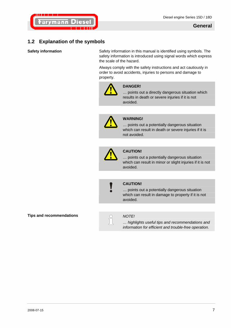
Safety information Safety information in this manual is identified using symbols. The safety information is introduced using signal words which express the scale of the hazard. Always comply with the safety instructions and act cautiously in order to avoid accidents, injuries to persons and damage to property.
DANGER! … points out a directly dangerous situation which results in death or severe injuries if it is not avoided.
WARNING! … points out a potentially dangerous situation which can result in death or severe injuries if it is not avoided.
CAUTION! … points out a potentially dangerous situation which can result in minor or slight injuries if it is not avoided.
CAUTION! … points out a potentially dangerous situation which can result in damage to property if it is not avoided.
Tips and recommendations
NOTE! … highlights useful tips and recommendations and information for efficient and trouble-free operation.
Diesel engine Series 15D / 18D
General
8 2008-07-15
1.3 Limitation of liability All information and instructions for use in this manual have been compiled taking account of the applicable standards and regulations, the latest state of technology and our many years of expertise and experience. The manufacturer accepts no liability for damage due to:
Non-observance of the instructions Improper use
Use of untrained personnel Unauthorised modifications
Technical changes Use of non-original spare parts
The actual scope of delivery can be different from the explanations and illustrations stated here for special versions, the use of additional ordered options or due to the latest technical changes.
The agreed obligations in the supply contract, the general terms and conditions and the delivery conditions of the manufacturer and the applicable legal regulations in force at the time of the conclusion of the contract are applicable.
We reserve the right to make technical modifications in order to improve usability.
Diesel engine Series 15D / 18D
General
2008-07-15 9
1.4 Copyright This Manual is protected by copyright law and exclusively to be used for internal purposes.
Passing this Manual on to third parties, duplication of any kind – even in form of excerpts – as well as the use and/or disclosure of the contents without the written consent of the manufacturer is not permitted, except for internal purposes.
Violations oblige to compensation. The right for further claims remains reserved.
1.5 Warranty terms
The warranty terms are provided in the manufacturer's terms and conditions.
1.6 Customer service Our customer service is pleased to provide further technical information. Please refer to our website (www.farymann.de) or telephone us on +49 (0)6206/507-0 for a list of our sales and service partners. Furthermore, our employees are always interested in new information and experience arising from use and which can be valuable for the improvement of our products.
Diesel engine Series 15D / 18D
Safety
10 2008-07-15
2 Safety
This paragraph provides an overview of all important safety aspects for optimal protection of personnel as well as safe and trouble-free operation.
Disregarding this Manual and safety regulations specified therein may result in considerable danger.
2.1 Customer’s responsibility
The system is used commercially. The owner of the machine is thus subject to the legal obligations for health and safety at work.
As well as the operational safety instructions in this operator's manual, the applicable safety, accident prevention and environmental regulations for the application must also be complied with. The following particularly apply:
The owner must inform himself about the applicable health and safety conditions and also determine hazards arising from the special operating conditions at the usage location of the machine in a risk analysis. He must implement this in the form of operating instructions for the operation of the machine.
During the complete usage time of the machine, the owner must check whether the operating instructions created by him correspond with the current status of the regulations and must adapt these if necessary.
The owner must clearly regulate and specify the responsibilities for installation, operation, maintenance and cleaning.
The owner must ensure that all employees involved with the machine have read and understood the operating instructions. He must also train the personnel and inform them about the dangers at regular intervals.
The owner must provide the necessary protective equipment for the personnel.
The owner is also responsible that the machine is always in proper working condition. Therefore, strictly observe the following:
The owner must ensure that the maintenance intervals specified in this manual are complied with.
The owner must arrange for all safety equipment to be checked regularly for functionality and completeness.
Explosive and easily flammable substances must always be kept away from the engine as the engine can become very hot during operation.
Do not touch rotating parts while the engine is running.
Diesel engine Series 15D / 18D
Safety
2008-07-15 11
Only fill with fuel when the engine is switched off. Do not fill in the vicinity of naked flames or ignitable sparks, do not smoke and do not spill any fuel.
This operator's manual must be kept in the immediate vicinity of the engine and must be accessible at any time to all persons working on and with the engine.
The engine must only be operated if it is in proper working condition. The engine must be checked for intactness before every start-up.
In the case of doubt, always contact the nearest Greaves Farymann Diesel service partner before starting the engine.
Only regular maintenance in accordance with the information in this operator's manual maintains the operational readiness of the engine.
Only perform maintenance and cleaning work when the engine is switched off.
Strictly observe all the information in the operator's manual.
Observe all warning and information signs on the engine and keep these in legible condition. If a warning or information sign should be lost or difficult to read, always request a replacement from the nearest Greaves Farymann Diesel service partner.
Diesel engine Series 15D / 18D
Safety
12 2008-07-15
2.2 Personnel requirements
2.2.1 Qualifications
WARNING! Danger of injury for unqualified personnel! Improper handling can result in severe personal injury and/or material damage. Therefore: – Have all jobs carried out by qualified personnel
only.
The following qualifications are specified for different areas of activity listed in the Manual.
Trained person has been instructed by the owner about the tasks assigned to him and possible dangers in the case of improper behaviour.
Technical personnel are persons who on the basis of their professional training by Greaves Farymann Diesel GmbH, experience and knowledge of the relevant conditions can perform the work assigned to them using the operating and repair instructions and can recognise and avoid possible dangers themselves.
Only persons who are expected to perform their tasks reliably are permitted as personnel. Persons whose reaction capability is impaired, e.g. through drugs, alcohol or medication are not permitted.
When selecting the personnel, the stipulations regarding age and occupation applying at the location must be observed.

Diesel engine Series 15D / 18D
Safety
2008-07-15 13
2.3 Appropriate use The system is designed and constructed exclusively for the intended purpose described here.
The engine is provided exclusively for the intended purpose which has been specified and tested by the manufacturer of the equipment in which the engine is installed. Any other use is considered to be improper. Greaves Farymann Diesel GmbH accepts no liability for any dangers and damage resulting from this. The risk is borne solely by the user.
The installation must be made so that all applicable safety regulations for the operation of diesel engines are complied with.
Proper use also includes compliance with all the information in this operator's manual. Any use beyond the intended use and/or other types of use is considered misuse and can result in dangerous situations.
WARNING! Danger due to misuse! Misuse can result in dangerous situations. Refrain particularly from the following uses of the system: – Operation of the engine while it is not in the
installed condition. – Operation of the engine without sufficient safety
devices. – Operation of the engine with non-approved
fuels.
Any types of claims for damage arising from improper use are excluded.
Diesel engine Series 15D / 18D
Safety
14 2008-07-15
2.4 Personal protective equipment Wearing of personal protective equipment is required when working to minimize the health hazards.
Always wear the protective equipment that is necessary for the respective task when working.
Follow the instructions on personal protective equipment that are posted in the work area.
Wear generally Generally wear for all kind of work:
Protective clothing is close fitting, with low resistance to tearing, with narrow sleeves and without protruding parts. It mainly provides protection against being entangled by moving machine parts.
Do not wear any rings and other jewellery.
Safety boots to protect against heavy parts falling down or slipping on slippery ground.
Personal protective equipment for special tasks
When performing special tasks it is necessary to wear personal protective equipment. This personal protective equipment will be separately specified in the chapters of this Manual. This special protective equipment is explained below.
Ear defenders to protect against hearing damage.
Hard hat to protect against parts and materials falling down and flying around.
Protective gloves to protect the hand against friction, graze, punctures or deep cuts as well as contact with hot surfaces.
Safety goggles to protect the eyes against parts flying around or squirts of fluids.
Diesel engine Series 15D / 18D
Safety
2008-07-15 15
2.5 Specific dangers The following section lists the residual risks that have been determined by the risk assessment.
Heed the safety instructions listed here, and the warnings in subsequent chapters of this Manual, to reduce health hazards and to avoid dangerous situations.
Rotating parts
WARNING! Risk of injury due to rotating parts Rotating parts can cause severe injuries. Therefore: – Do not reach into or work on rotating parts
during operation. – Do not open or remove covers during operation. – Pay attention to the run-on time after switching
off the engine. Ensure there are no parts still moving or the engine is not running before opening the covers.
– Wear close-fitting work clothing.
Diesel engine Series 15D / 18D
Safety
16 2008-07-15
Substances harmful to health
WARNING! Danger of poisoning and danger of skin rashes and allergies! Fuels and lubricants contain substances harmful to health and can result in severe poisoning and skin rashes or allergies. Therefore: – Observe the safety data sheet of the
manufacturer of fuels and lubricants. – Avoid spilling fuels and fog formation. – In the case of inhalation, bring affected person
into the open air immediately. Contact a doctor. – Contact doctor immediately in the case of
swallowing. Rinse mouth thoroughly with water. – Avoid skin and eye contact:
Apply suitable skin protection cream before working on tanks, piping or supply equipment. Wear protective gloves made of plastic or rubber during the work.
– In the case of contact with the skin or eyes, rinse immediately with a lot of water. Contact a doctor.
– Dispose of contamination in the working area properly and in accordance with environmental regulations. Fuels and lubricants must not get into the sewer system.
– Do not eat, drink or smoke when working.
Diesel engine Series 15D / 18D
Safety
2008-07-15 17
Highly flammable materials
WARNING! Fire hazard by highly flammable materials! Highly flammable materials, liquids or gases may catch fire causing serious and even fatal injuries. Therefore: – Do not smoke within the danger zone and the
immediate vicinity. Avoid using open flames or ignition sources.
– Keep a fire extinguisher ready. – Report suspicious materials, liquids or gases
immediately to the person in charge. – Suspend any work activities in case of fire.
Leave the danger zone until the all clear signal is given.
Hot operating materials
WARNING! Risk of burns due to hot operating materials! Operating materials can reach high temperatures during operation and cause burns in the case of contact. Therefore: – Check whether operating materials are hot
before handling them. If necessary, let them cool down to the ambient temperature.
Hot surfaces of the engine components
CAUTION! Risk of burns due to hot surfaces of the engine components! Contact with hot surfaces can cause burns. Therefore: – Always wear protective clothing and protective
gloves for all work in the vicinity of hot parts. – Ensure that all parts have cooled down to the
ambient temperature before all work.
Diesel engine Series 15D / 18D
Safety
18 2008-07-15
2.6 Safety devices
WARNING! Risk of injury due to non-functional safety devices! Safety is only ensured if the safety devices are intact. Therefore: – Check whether the safety devices are functional
and correctly installed before starting work. – Never deactivate safety devices.
NOTE! See the Chapter "Design and function" for detailed information about the position of the safety devices.
2.7 Behaviour in the case of danger and accidents
Preventive measures Always be prepared for accidents or fire. Keep first aid equipment (first aid kit, blankets etc.) and fire
extinguishers ready to hand.
Familiarise personnel with accident reporting, first aid and rescue equipment.
Keep access routes clear for rescue vehicles.
Actions in the case of accidents Operate the EMERGENCY STOP button on the machine (if present) immediately.
Initiate first aid actions. Rescue people from the danger zone.
Inform the responsible person at the usage location. Notify the rescue services.
Keep access routes clear for rescue vehicles.
Diesel engine Series 15D / 18D
Safety
2008-07-15 19
2.8 Environmental protection
CAUTION! Danger to the environment due to mishandling! Significant environmental damage can occur, particularly for incorrect disposal, if environmentally hazardous operating materials are mishandled. Therefore: – Always observe the instructions mentioned
below. – Take immediate action if environmentally
hazardous materials reach the environment. Inform the responsible local authorities about the damage in the case of doubt.
The following environmentally hazardous substances are used:
Lubricants, fuels Fuels and lubricants such as, e.g. diesel fuel and engine oil contain toxic substances. They must not reach the environment. The disposal must be performed by a specialist disposal company.

Diesel engine Series 15D / 18D
Technical data
20 2008-07-15
3 Technical data
3.1 Technical specifications
Fig. 1
Single-cylinder, four-stroke diesel engine, air-cooled, with the following characteristics:
Direct injection (Bosch injection system)
Power take-off at the flywheel Safe manual start with starting handle or electric starter
Automatic decompression and excess fuel device Self-venting fuel system
Mechanical speed governor Oil forced-feed lubrication system with gear pump, oil filter for
increased operational reliability Exhaust silencer
Dry type air cleaner or oil bath air cleaner Fuel tank and fuel filter
Crankcase of high tensile light alloy Plain bearings on conrod and crankshaft on the control side
Roller bearing on output side Cooling fan integrated in the flywheel
Engine mounting points integrally cast on the crankcase Environmentally friendly due to internal crankcase venting and
valve stem seals
3.2 Applications
The engine series 15D/18D is suitable, for example, for the following applications:
Construction equipment Agricultural applications Generators Water pumps Compressors Special applications (according to customer requirements)
Diesel engine Series 15D / 18D
Technical data
2008-07-15 21
3.3 Standard configuration The engine is delivered with the following standard configuration:
3.9 litre fuel tank Fuel filter
Dry type air cleaner, optional oil bath air cleaner Exhaust silencer
Crank handle (rigid)
3.4 Options The engine is available with the following options:
4.0 litre fuel tank
Fuel feed pump Starter (12 V or 24 V)
Solenoid valve open or closed with zero current (12 V or 24 V) Alternator (12 V or 24 V)
Stub shafts (various versions) Bell housings (various versions)
Additional oil sump Oil preheater (1 heating element, 12 V or 24 V)
Air intake preheater (2 heating elements, 12 V or 24 V) Crank handle RD (limited kickback)
3.5 Engine type plate
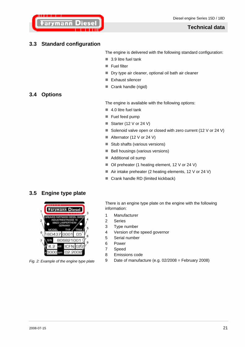
Fig. 2: Example of the engine type plate
There is an engine type plate on the engine with the following information: 1 Manufacturer 2 Series 3 Type number 4 Version of the speed governor 5 Serial number 6 Power 7 Speed 8 Emissions code 9 Date of manufacture (e.g. 02/2008 = February 2008)
Diesel engine Series 15D / 18D
Technical data
22 2008-07-15
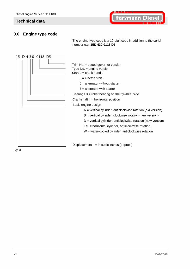
3.6 Engine type code The engine type code is a 12-digit code in addition to the serial number e.g. 15D 430.0118 D5
Fig. 3
Trim No. = speed governor version Type No. = engine version Start 0 = crank handle
5 = electric start 6 = alternator without starter
7 = alternator with starter Bearings 3 = roller bearing on the flywheel side
Crankshaft 4 = horizontal position Basic engine design
A = vertical cylinder, anticlockwise rotation (old version) B = vertical cylinder, clockwise rotation (new version)
D = vertical cylinder, anticlockwise rotation (new version) E/F = horizontal cylinder, anticlockwise rotation W = water-cooled cylinder, anticlockwise rotation
Displacement = in cubic inches (approx.)
Diesel engine Series 15D / 18D
Technical data
2008-07-15 23
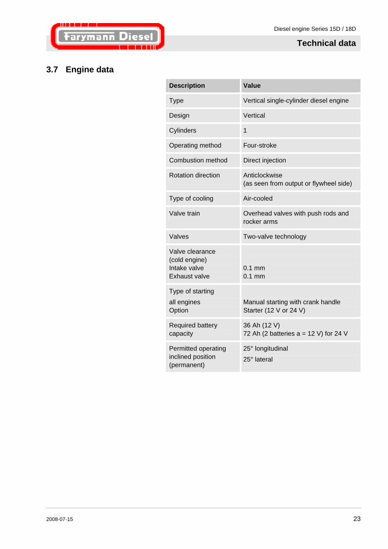
3.7 Engine data
Description Value
Type Vertical single-cylinder diesel engine
Design Vertical
Cylinders 1
Operating method Four-stroke
Combustion method Direct injection
Rotation direction Anticlockwise (as seen from output or flywheel side)
Type of cooling Air-cooled
Valve train Overhead valves with push rods and rocker arms
Valves Two-valve technology
Valve clearance (cold engine) Intake valve Exhaust valve
0.1 mm 0.1 mm
Type of starting all engines Option
Manual starting with crank handle Starter (12 V or 24 V)
Required battery capacity
36 Ah (12 V) 72 Ah (2 batteries a = 12 V) for 24 V
Permitted operating inclined position (permanent)
25° longitudinal 25° lateral

Diesel engine Series 15D / 18D
Technical data
24 2008-07-15
3.8 Performance data
Description Value 15D Value 18D
Max. power (at 3600 rpm)
IFN-ISO* 3.9 kW ICFN-ISO* 3.5 kW
IFN-ISO* 4.7 kW ICFN-ISO* 4.2 kW
Max. speed 3600 rpm
Max. torque at min-1
11.5 Nm 2500 rpm
13.6 Nm 2500 rpm
Bore 82 mm
Stroke 55 mm
Displacement 290 cm3
Mean piston speed
6.6 m/s (3600 rpm)
Compression ratio 20:1
* IFN-ISO Blocked performance for intermittent load.
* ICFN-ISO Power for constant speed and constant load. Contact the manufacturer for continuous use outside the stated performance limit.
Power reduction Reduction approx. 1% for each 100 m height and approx. 2% for each 5 °C over 20 °C. Performance guaranteed with 5 % deviation for the run-in engine with standard air filter and exhaust silencer.
3.9 Dimensions and weight
Description Value
Overall length 310 mm
Overall height 450 mm
Overall width 370 mm
Dry weight: standard engine with fuel tank, air filter and exhaust silencer
41 kg
Diesel engine Series 15D / 18D
Technical data
2008-07-15 25
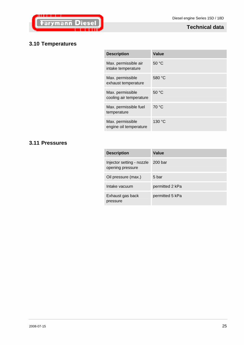
3.10 Temperatures
Description Value
Max. permissible air intake temperature
50 °C
Max. permissible exhaust temperature
580 °C
Max. permissible cooling air temperature
50 °C
Max. permissible fuel temperature
70 °C
Max. permissible engine oil temperature
130 °C
3.11 Pressures
Description Value
Injector setting - nozzle opening pressure
200 bar
Oil pressure (max.) 5 bar
Intake vacuum permitted 2 kPa
Exhaust gas back pressure
permitted 5 kPa
Diesel engine Series 15D / 18D
Technical data
26 2008-07-15
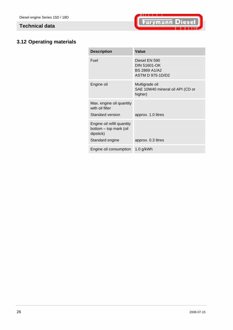
3.12 Operating materials
Description Value
Fuel Diesel EN 590 DIN 51601-OK BS 2869 A1/A2 ASTM D 975-1D/D2
Engine oil Multigrade oil SAE 10W40 mineral oil API (CD or higher)
Max. engine oil quantity with oil filter
Standard version
approx. 1.0 litres
Engine oil refill quantity bottom – top mark (oil dipstick)
Standard engine
approx. 0.3 litres
Engine oil consumption 1.0 g/kWh
Diesel engine Series 15D / 18D
Technical data
2008-07-15 27
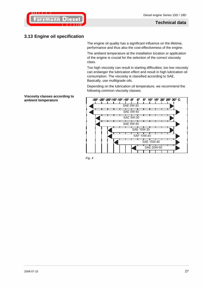
3.13 Engine oil specification The engine oil quality has a significant influence on the lifetime, performance and thus also the cost-effectiveness of the engine.
The ambient temperature at the installation location or application of the engine is crucial for the selection of the correct viscosity class.
Too high viscosity can result in starting difficulties; too low viscosity can endanger the lubrication effect and result in high lubrication oil consumption. The viscosity is classified according to SAE. Basically, use mulltigrade oils.
Depending on the lubrication oil temperature, we recommend the following common viscosity classes.
Viscosity classes according to ambient temperature
Fig. 4
Diesel engine Series 15D / 18D
Structure and function
28 2008-07-15
4 Structure and function
4.1 Overview
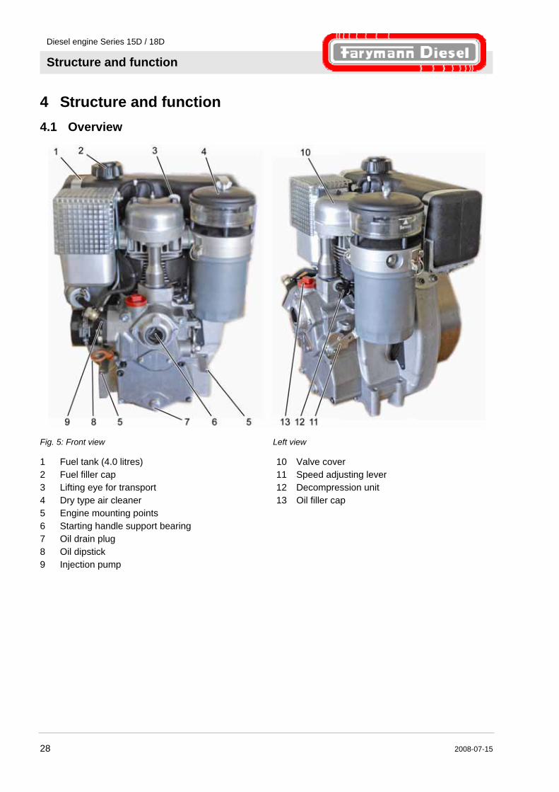
Fig. 5: Front view Left view
1 Fuel tank (4.0 litres) 2 Fuel filler cap 3 Lifting eye for transport 4 Dry type air cleaner 5 Engine mounting points 6 Starting handle support bearing 7 Oil drain plug 8 Oil dipstick 9 Injection pump
10 Valve cover 11 Speed adjusting lever 12 Decompression unit 13 Oil filler cap
Diesel engine Series 15D / 18D
Structure and function
2008-07-15 29
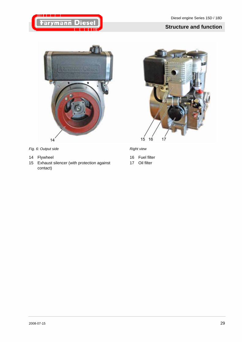
Fig. 6: Output side Right view
14 Flywheel 15 Exhaust silencer (with protection against
contact)
16 Fuel filter 17 Oil filter
Diesel engine Series 15D / 18D
Structure and function
30 2008-07-15
4.2 Electrical System 4.2.1 Alternator (option)
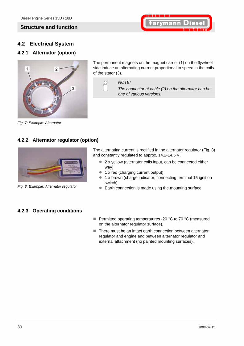
Fig. 7: Example: Alternator
The permanent magnets on the magnet carrier (1) on the flywheel side induce an alternating current proportional to speed in the coils of the stator (3).
NOTE! The connector at cable (2) on the alternator can be one of various versions.
4.2.2 Alternator regulator (option)
Fig. 8: Example: Alternator regulator
The alternating current is rectified in the alternator regulator (Fig. 8) and constantly regulated to approx. 14.2-14.5 V.
2 x yellow (alternator coils input, can be connected either way)
1 x red (charging current output) 1 x brown (charge indicator, connecting terminal 15 ignition
switch) Earth connection is made using the mounting surface.
4.2.3 Operating conditions Permitted operating temperatures -20 °C to 70 °C (measured
on the alternator regulator surface).
There must be an intact earth connection between alternator regulator and engine and between alternator regulator and external attachment (no painted mounting surfaces).
Diesel engine Series 15D / 18D
Structure and function
2008-07-15 31
4.2.4 Dangers and cause of failure
Dangers Cause of failure
Battery terminals incorrectly connected
Damage to the charging circuit
Defective battery or complete discharge
Destruction of the alternator regulator
Disconnection of the battery when the engine is running
Immediate destruction of the alternator regulator
External start with jump leads for defective or completely discharged battery
Destruction of the alternator regulator
Manual starting with disconnected battery
Destruction of the alternator regulator
Interruption of the earth connection of the alternator regulator to the engine
Destruction of the alternator regulator
Welding work
WARNING! Material damage due to welding work on the machine! Welding work on the machine can cause high material damage. Therefore: – always disconnect the negative pole of the
battery in advance. – disconnect the plug connection to the
alternator regulator.
Diesel engine Series 15D / 18D
Structure and function
32 2008-07-15
4.2.5 Batteries
Observe the following safety factors: Batteries produce explosive gases. Keep away from naked flames and other ignition sources. Do
not smoke. Do not lay any tools on the battery.
Always disconnect the negative pole of the battery before performing work on the electrical system.
Do not mix up the + (plus) and - (minus) poles of the battery.
Connect the plus cable first and the minus cable afterwards when installing the battery.
Disconnect the minus cable first and the plus cable afterwards when removing the battery.
Always avoid short-circuits and earth contact of live cables.
In the case of faults in the electrical system, first check the cable connections for good contact.
Replace defective indicator lamps immediately.
Do not remove the ignition key during operation. Do not disconnect the battery while the engine is running
(occurring voltage peaks can destroy electronic components, e.g. the alternator regulator).
Do not spray parts of the electrical system during engine cleaning with a water jet or high pressure jet.
Always disconnect the minus terminal of the battery and disconnect the plug connection to the alternator regulator for welding work.
Batteries
WARNING! Risk of injury due to incorrect handling of batteries! Batteries must be handled with particular caution. Therefore: – Never expose batteries to high temperatures.
There is a risk of explosion. – Escaping liquid due to incorrect use can result
in skin rashes. Avoid contact with the liquid. Always rinse with a lot of water in the case of contact with the liquid. If the liquid gets into the eyes, rinse immediately with water and contact a doctor immediately.
Diesel engine Series 15D / 18D
Transport, packing and storage
2008-07-15 33
5 Transport, packing and storage
5.1 Safety notes for transport
Improper transport
CAUTION! Damage due to improper transport! Significant damage to property and injuries to persons can occur in the case of improper transport. Therefore: – Proceed carefully when unloading the packages
and on delivery and internal transport and observe the signs and notices on the packing.
– Only use the attachment points provided. – Do not remove packing until just before the
installation.
5.2 Transport inspection
Check the delivery immediately on receipt for completeness and transport damage. If externally detectable transport damage is found, proceed as follows:
Do not accept the delivery, or only with reservation. Record the extent of transport damage in the transport
documents or on the delivery note of the forwarding agent. Start complaints procedure.
NOTE! Claim any damage as soon as it is detected. Compensation claims can only be submitted within the applicable complaints periods.
Diesel engine Series 15D / 18D
Transport, packing and storage
34 2008-07-15
5.3 Packing
Concerning packing The individual packages have been packed to match the transport conditions that can be expected. Only environmentally friendly materials were used for packing. The packing has the function of protecting the individual components against damage, corrosion, etc., until they are finally assembled. The packing material must therefore not be damaged and should only be removed just before assembly takes place.
Handling packing materials If there is no returns agreement for the packing, separate materials according to type and size and direct to further use or recycling.
CAUTION! Environmental damage caused by incorrect waste disposal! Packing materials are valuable raw materials and can continue to be used in many cases or sensibly reconditioned and recycled. Therefore: – Dispose of packing materials environmentally. – Follow the locally valid waste disposal
regulations. If necessary employ a special waste disposal company to dispose of packing material.

Diesel engine Series 15D / 18D
Transport, packing and storage
2008-07-15 35
5.4 Transport
Transport of the engine with the crane
Fig. 9: Transport with the crane
The engine has one lifting eye (fig. Fig. 9/1) and can be transported directly with a crane under the following conditions:
Crane and lifting gear must be designed for the weight of the engine.
Only lift and transport the engine in the normal position (engine mounting points at the bottom).
The operator must wear a safety helmet, safety shoes and protective gloves and must be authorised to operate the crane.
Attaching: 1. Attach ropes, belts or chains accordingly (Fig. 9). 2. Ensure that the engine is attached straight.
3. Do not start the transport until then.
Storage of the engine Store new engines under the following conditions:
Do not store outdoors. Store dry and dust-free.
Do not expose to any aggressive media. Protect against direct sunlight.
Avoid mechanical vibrations. Storage temperature: 15 to 35 °C. Relative humidity: max. 60 %.
In the case of storage for longer than 3 months, check the general condition of all parts and the packing regularly. If required, refresh or renew the anti-corrosion protection.
Storage of the engines up to 12 months is possible under the above conditions.
CAUTION! Damage due to improper storage! Parts of the engine can corrode and become non-functional in the case of too high relative humidity or air containing salt. Therefore: – In the case of storage for longer than 6 months,
contact the nearest Greaves Farymann Diesel service partner in order to agree suitable precautions.

Diesel engine Series 15D / 18D
Installation and commissioning
36 2008-07-15
6 Installation and commissioning
6.1 Safety Personnel Installation and commissioning may be executed only by
specially trained personnel. All work on the electrical system must be performed by a
qualified electrician.
6.2 Installation
6.2.1 Mounting the flywheel Must only be performed by a specialist. Additional protective equipment required:
Safety footwear
Special tool needed:
Torque wrench
Fig. 10
NOTE! Always check the flywheel nut with a torque wrench for 216 to 226 Nm before every installation in or attachment to the machine.
1. Install engine on suitable mounting. 2. Turn engine slowly with the crank handle until the keyway (1)
in the crankshaft (3) faces upwards.
NOTE! This position makes installation of the flywheel easier.
3. Place both plate washers (2) on the crankshaft (3).
NOTE! The flat sides of the plate washers face each other.

Diesel engine Series 15D / 18D
Installation and commissioning
2008-07-15 37
Fig. 11
4. Install key (4) into the keyway of the crankshaft and ensure that this sits correctly.
Fig. 12
5. Install the flywheel (5) ensuring that it is not twisted during the installation.
NOTE! In the case of improper installation of the flywheel, the magnets of the magnet carrier (e.g. for engines with alternator) can be damaged. The alternator does not function correctly if the magnets are damaged.

Diesel engine Series 15D / 18D
Installation and commissioning
38 2008-07-15
Fig. 13
Fig. 14
6. After the installation of the flywheel, check without fail that the key is correctly seated in the keyway of the crankshaft before screwing on the flywheel nut.
NOTE! In the case of improper mounting of the flywheel, the key can fall out of the crankshaft keyway. This results in the flywheel not being correctly fixed. Due to the missing key, the flywheel nut can slacken when starting the engine. This results in the crankshaft and the flywheel being severely damaged.
7. Screw on the flywheel nut as far as possible by hand.
NOTE! In doing so, ensure that the machined flat side (arrow) of the flywheel nut is facing the crankshaft.
8. Screw two bolts (6) into the thread provided on the flywheel. 9. Fix the flywheel with a suitable lever (e.g. tyre lever) (7).
10. Tighten the flywheel nut with a torque wrench (8) to 216 - 226 Nm.
11. Turn the flywheel by hand and examine for unobstructed movement (must not jam).
6.2.2 Attaching stub shaft (option)
Fig. 15: Example: Stub shaft
Example: Not all applications need a stub shaft. 12. Attach stub shaft (1) to the flywheel.
NOTE! Depending on the type of installation, the stub shaft can be different from that shown in the picture.
Diesel engine Series 15D / 18D
Installation and commissioning
2008-07-15 39
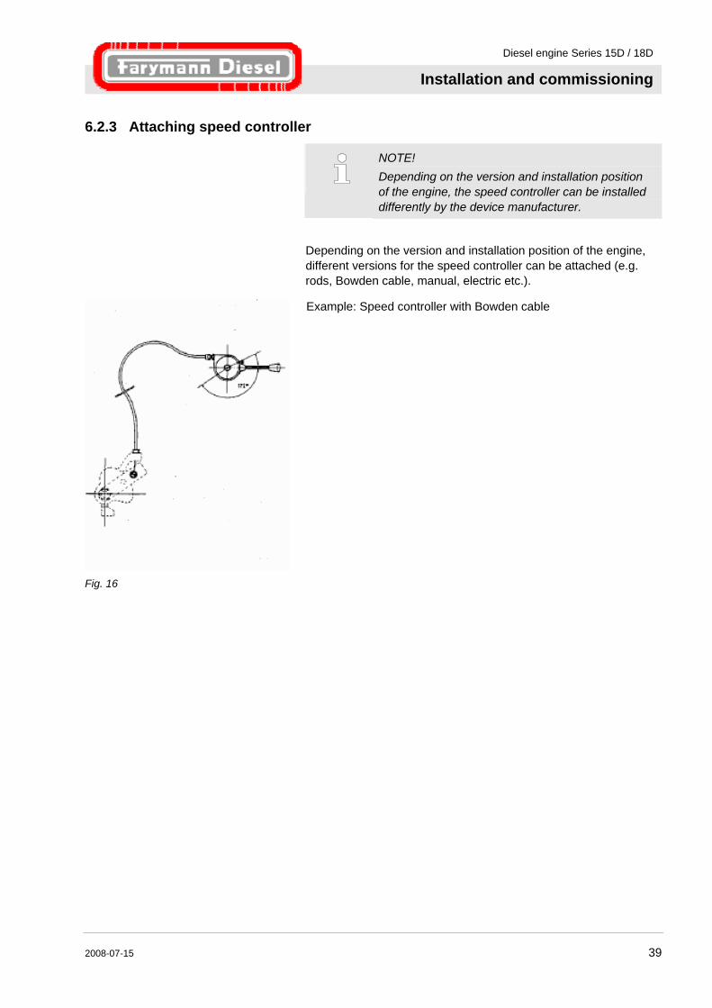
6.2.3 Attaching speed controller
NOTE! Depending on the version and installation position of the engine, the speed controller can be installed differently by the device manufacturer.
Depending on the version and installation position of the engine, different versions for the speed controller can be attached (e.g. rods, Bowden cable, manual, electric etc.).
Fig. 16
Example: Speed controller with Bowden cable
Diesel engine Series 15D / 18D
Installation and commissioning
40 2008-07-15
6.3 Initial commissioning
CAUTION! Engine damage due to missing operating materials! The engine is delivered without operating materials. Operation without all required operating materials can destroy the engine. Therefore: – Fill with engine oil and diesel fuel before first
use. – Only use operating materials which are
specified in the technical data. – Observe the filling quantities. – Before first use or after a long decommissioning
(more than 6 months), operate the engine after starting for approx. 1 minute at low speed and without load. Due to this action, an optimum lubrication of all bearings is achieved and a lack of lubrication is avoided.
CAUTION! Engine damage due to cold start aids! The use of cold starting aid results in engine damage. Therefore: – Never use cold starting aids.
Diesel engine Series 15D / 18D
Installation and commissioning
2008-07-15 41
6.4 Filling with engine oil
CAUTION! Engine damage due to incorrect oil quantity! Too high or too low oil level can result in damage to the engine. Therefore: – Never exceed the maximum level.
Never drop below the minimum level. – The engine must stand up straight for checking
the oil level.
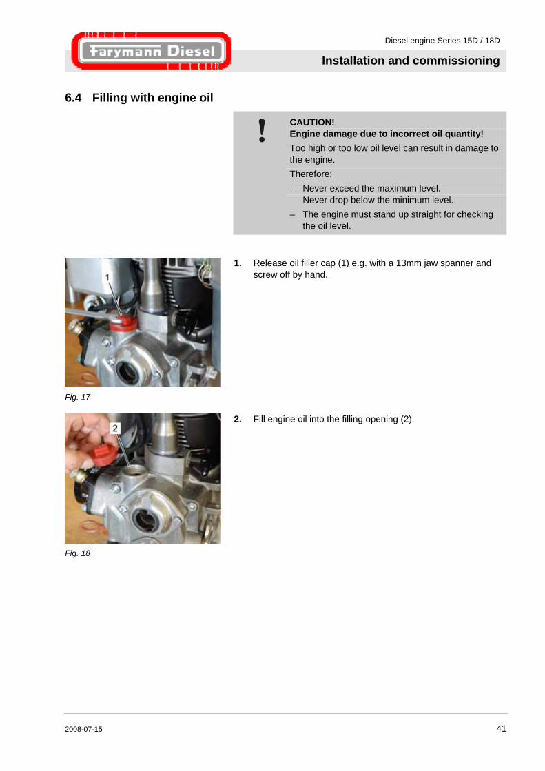
Fig. 17
1. Release oil filler cap (1) e.g. with a 13mm jaw spanner and screw off by hand.
Fig. 18
2. Fill engine oil into the filling opening (2).

Diesel engine Series 15D / 18D
Installation and commissioning
42 2008-07-15
Fig. 19
3. Pull out oil dipstick (3) and clean the bottom end with a clean and fluff-free cloth.
4. Replace the oil dipstick (3) and pull it out again.
Fig. 20
5. Check the oil level quantity. The oil level should be just under the Max. marking.
6. Fill with engine oil if needed.
Fig. 21
7. Only tighten the oil filler cap (1) by hand (risk of breakage).
Diesel engine Series 15D / 18D
Installation and commissioning
2008-07-15 43
6.5 Filling with fuel
CAUTION! Engine damage due to contaminated fuel! The injection system and the engine can be damaged by dirt particles or other contamination in the fuel. Therefore: – Only fill with clean diesel fuel according to EN
5090, DIN 590. – Pay attention to cleanliness so that no dirt gets
into the fuel tank. – The engine must stand up straight for filling with
fuel.
NOTE! Use winter diesel fuel for temperatures below 0 °C. The fuel filler cap (Fig. 22/1) has a vent. Do not make any modifications or use a non-original fuel filler cap. Otherwise, optimum fuel supply is not guaranteed. Fill the tank to the maximum before first use or after the fuel system runs empty. In this way, the venting of the fuel system is performed automatically (self-venting fuel system).
6.5.1 Filling process 4.0 litre tank (option)
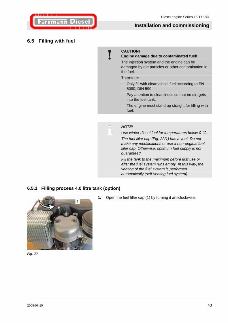
Fig. 22
1. Open the fuel filler cap (1) by turning it anticlockwise.
Diesel engine Series 15D / 18D
Installation and commissioning
44 2008-07-15
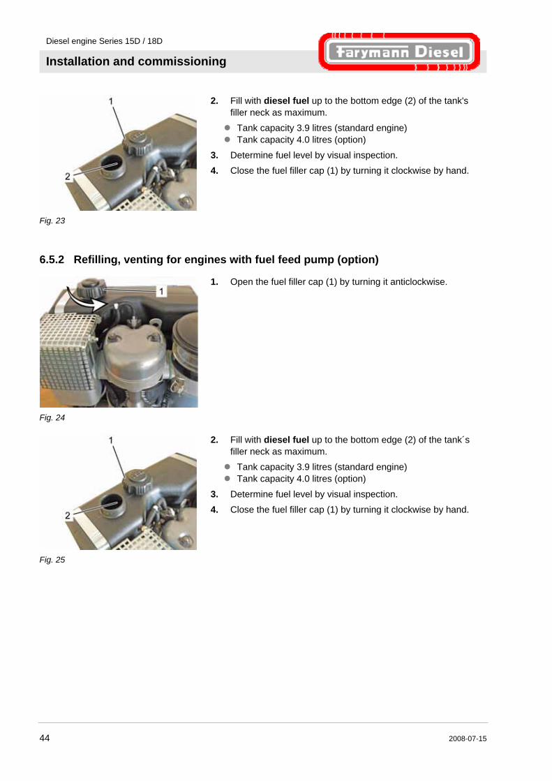
Fig. 23
2. Fill with diesel fuel up to the bottom edge (2) of the tank's filler neck as maximum. Tank capacity 3.9 litres (standard engine) Tank capacity 4.0 litres (option)
3. Determine fuel level by visual inspection. 4. Close the fuel filler cap (1) by turning it clockwise by hand.
6.5.2 Refilling, venting for engines with fuel feed pump (option)
Fig. 24
1. Open the fuel filler cap (1) by turning it anticlockwise.
Fig. 25
2. Fill with diesel fuel up to the bottom edge (2) of the tank´s filler neck as maximum. Tank capacity 3.9 litres (standard engine) Tank capacity 4.0 litres (option)
3. Determine fuel level by visual inspection. 4. Close the fuel filler cap (1) by turning it clockwise by hand.
Diesel engine Series 15D / 18D
Installation and commissioning
2008-07-15 45
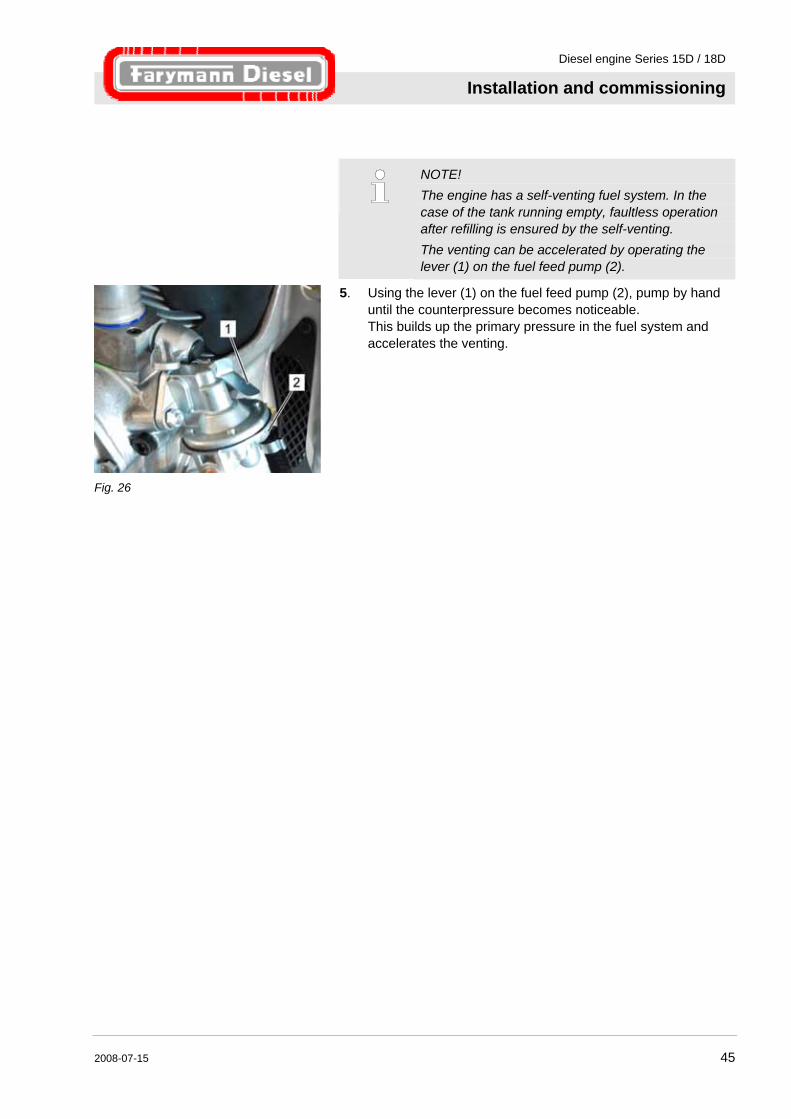
NOTE! The engine has a self-venting fuel system. In the case of the tank running empty, faultless operation after refilling is ensured by the self-venting. The venting can be accelerated by operating the lever (1) on the fuel feed pump (2).
Fig. 26
5. Using the lever (1) on the fuel feed pump (2), pump by hand until the counterpressure becomes noticeable. This builds up the primary pressure in the fuel system and accelerates the venting.
Diesel engine Series 15D / 18D
Operation
46 2008-07-15
7 Operation
7.1 Safety
Improper operation
WARNING! Risk of injury due to improper operation! Improper operation can result in severe personal injuries or material damage. Therefore: – Perform all the operating steps in accordance
with the information in this operator´s manual. – Ensure that all covers and safety devices are
installed and in proper working condition before starting the work.
– Never deactivate safety equipment during operation.
– Ensure tidiness and cleanliness in the working area. Loose components and tools lying around or on top of each other are sources of accidents.
Rotating parts
WARNING! Risk of injury due to rotating parts Rotating parts can cause severe injuries. Therefore: – Do not reach into or work on rotating parts
during operation. – Do not open covers during operation. – Note the run-on time of 10 to 20 seconds of the
engine: Ensure there are no parts still moving and the engine is not running before opening the covers.
– Wear close-fitting clothing in the danger zone.
Diesel engine Series 15D / 18D
Operation
2008-07-15 47
Exhaust gases
WARNING! Danger of poisoning due to exhaust gases! There is a danger of poisoning by odourless carbon monoxide of the exhaust gases are inhaled. Therefore: – Never inhale the exhaust gases. – Only operate the engine in well-ventilated
areas.
Hot surfaces of the engine components
CAUTION! Risk of burns due to hot surfaces of the engine components! The engine can become very hot during operation. Contact with the exhaust system and the engine can cause burns. Therefore: – Never touch the engine during operation. – Ensure that all parts have cooled down to the
ambient temperature before all work.
Engine oil and fuel
WARNING! Danger of fire due to fuel and engine oil! Oil and fuel vapours can ignite on contact with ignition sources. Therefore: – No naked flames during work on the engine. – Do not smoke. – Remove oil and fuel residues from the engine
and floor.
CAUTION! Danger of poisoning due to fuel and engine oil! Contact with engine oil and fuel can result in damage to health. Therefore: – Avoid skin contact with engine oil and fuel. – Remove oil and fuel splashes from the skin
immediately. – Do not inhale oil and fuel vapours.
Diesel engine Series 15D / 18D
Operation
48 2008-07-15
Personal protective equipment Wear the following protective equipment for all operation work: Protective clothing
Safety footwear
NOTE! Protective equipment which must be worn for certain work is specially pointed out in the warnings of this chapter.
The engine must be switched off as quickly as possible in dangerous situations.
Emergency shutdown Proceed as follow in the case of danger: 1. Switch off the engine immediately.
2. Inform the responsible person at the usage location. 3. Rescue people from the danger zone, initiate First Aid actions.
4. Switch off the main switch on the machine (if present) and secure it against being switched on again.
5. Keep access routes clear for rescue vehicles.
After the rescue actions 6. If required for the severity of the emergency, inform the responsible authorities.
7. Assign specialist personnel to the fault rectification.
WARNING! Risk of fatal injury due to premature restarting! There is a risk of fatal injury for all persons in the danger zone when the machine is restarted. Therefore: – Ensure there are no persons in the danger zone
before restarting.
8. Before restarting, ensure that all safety devices are installed and functional.
Diesel engine Series 15D / 18D
Operation
2008-07-15 49
7.2 Preparing for start
Checks Carry out the following checks in order to avoid damage to the engine:
Check engine oil level, refill with engine oil if necessary. Check fuel level, refill with diesel fuel if necessary.
Check air filter for soiling, clean if necessary or replace air filter element.
Check engine mounting. Check machine for completeness of the safety equipment.
Check engine and machine for missing covers. Check engine for damaged oil and fuel lines.
Check engine for damaged electrical cables and insulation. Check engine for leaks.
Ensure sufficient supply of combustion and cooling air.
Diesel engine Series 15D / 18D
Operation
50 2008-07-15
Setting cold start / warm start
CAUTION! Engine damage due to cold start aids! The use of cold starting aid results in engine damage. Therefore: – Never use cold starting aids.
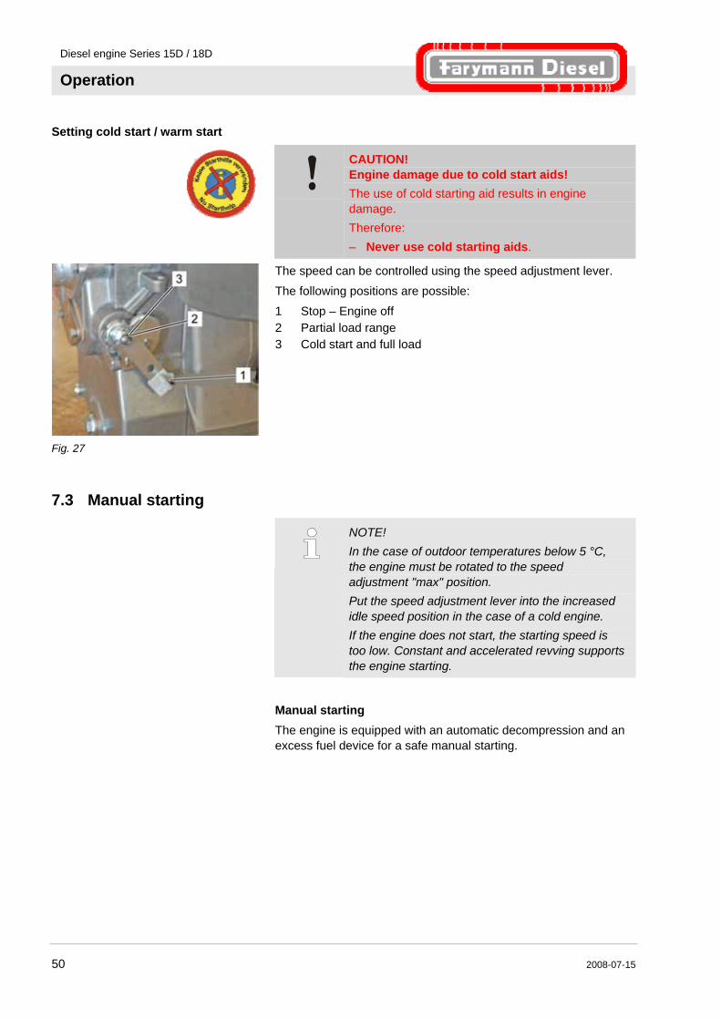
Fig. 27
The speed can be controlled using the speed adjustment lever. The following positions are possible: 1 Stop – Engine off 2 Partial load range 3 Cold start and full load
7.3 Manual starting
NOTE! In the case of outdoor temperatures below 5 °C, the engine must be rotated to the speed adjustment "max" position. Put the speed adjustment lever into the increased idle speed position in the case of a cold engine. If the engine does not start, the starting speed is too low. Constant and accelerated revving supports the engine starting.
Manual starting The engine is equipped with an automatic decompression and an excess fuel device for a safe manual starting.
Diesel engine Series 15D / 18D
Operation
2008-07-15 51
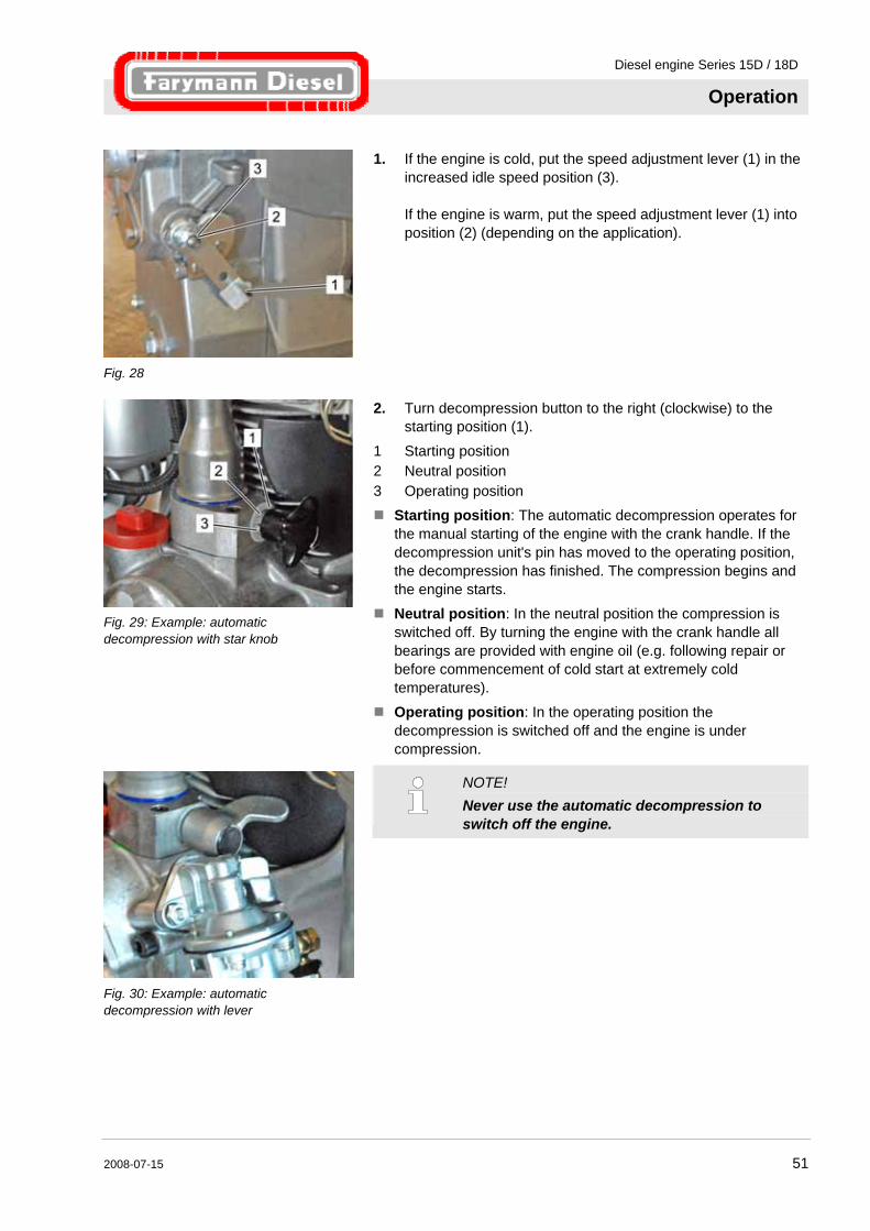
Fig. 28
1. If the engine is cold, put the speed adjustment lever (1) in the increased idle speed position (3). If the engine is warm, put the speed adjustment lever (1) into position (2) (depending on the application).
Fig. 29: Example: automatic decompression with star knob
2. Turn decompression button to the right (clockwise) to the starting position (1).
1 Starting position 2 Neutral position 3 Operating position
Starting position: The automatic decompression operates for the manual starting of the engine with the crank handle. If the decompression unit's pin has moved to the operating position, the decompression has finished. The compression begins and the engine starts.
Neutral position: In the neutral position the compression is switched off. By turning the engine with the crank handle all bearings are provided with engine oil (e.g. following repair or before commencement of cold start at extremely cold temperatures).
Operating position: In the operating position the decompression is switched off and the engine is under compression.
Fig. 30: Example: automatic decompression with lever
NOTE! Never use the automatic decompression to switch off the engine.
Diesel engine Series 15D / 18D
Operation
52 2008-07-15
Excess fuel device
NOTE! The excess fuel device (Fig. 31/1) must be pulled out for cold starting.
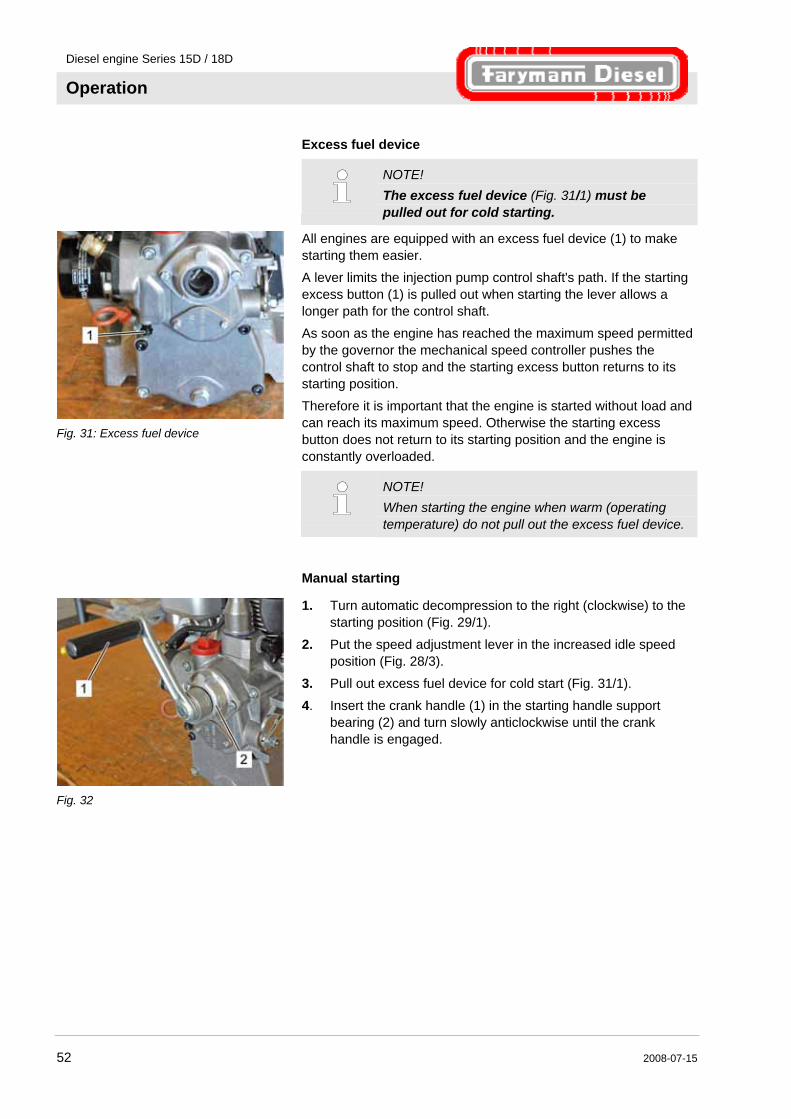
Fig. 31: Excess fuel device
All engines are equipped with an excess fuel device (1) to make starting them easier. A lever limits the injection pump control shaft's path. If the starting excess button (1) is pulled out when starting the lever allows a longer path for the control shaft. As soon as the engine has reached the maximum speed permitted by the governor the mechanical speed controller pushes the control shaft to stop and the starting excess button returns to its starting position. Therefore it is important that the engine is started without load and can reach its maximum speed. Otherwise the starting excess button does not return to its starting position and the engine is constantly overloaded.
NOTE! When starting the engine when warm (operating temperature) do not pull out the excess fuel device.
Manual starting
Fig. 32
1. Turn automatic decompression to the right (clockwise) to the starting position (Fig. 29/1).
2. Put the speed adjustment lever in the increased idle speed position (Fig. 28/3).
3. Pull out excess fuel device for cold start (Fig. 31/1). 4. Insert the crank handle (1) in the starting handle support
bearing (2) and turn slowly anticlockwise until the crank handle is engaged.
Diesel engine Series 15D / 18D
Operation
2008-07-15 53
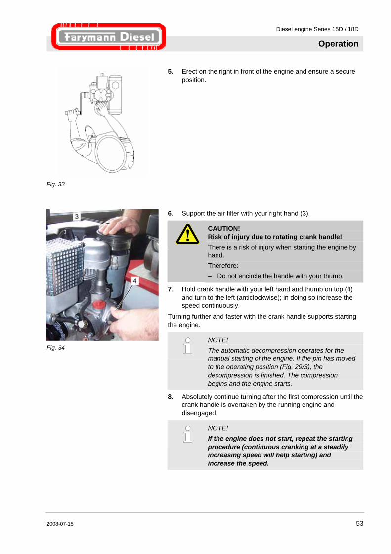
Fig. 33
5. Erect on the right in front of the engine and ensure a secure position.
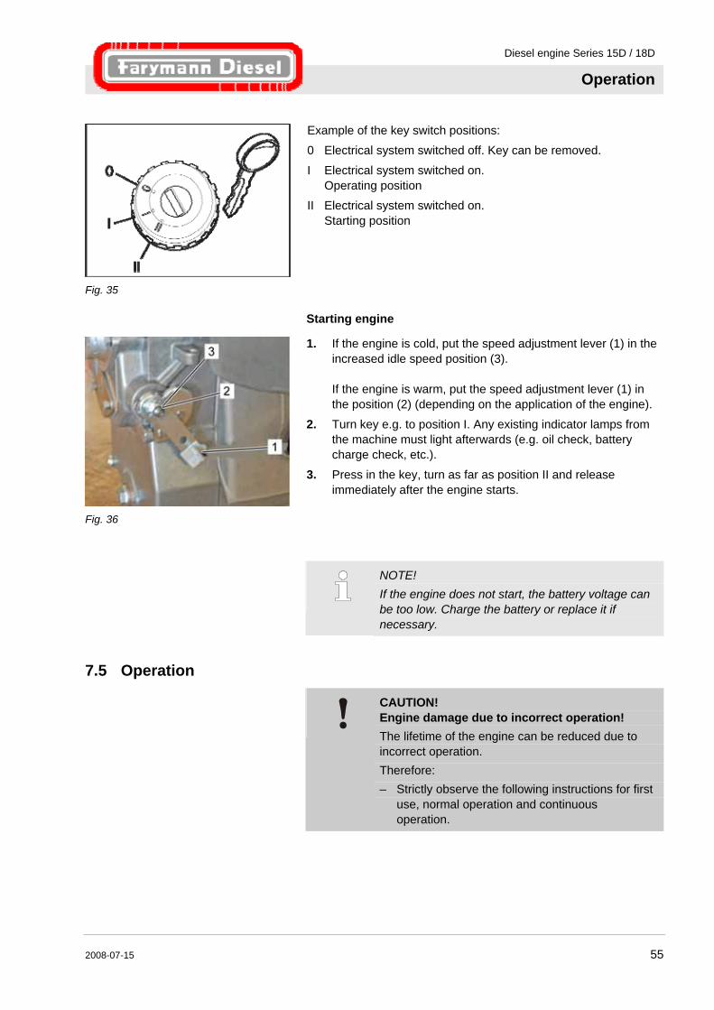
Fig. 34
6. Support the air filter with your right hand (3).
CAUTION! Risk of injury due to rotating crank handle! There is a risk of injury when starting the engine by hand. Therefore: – Do not encircle the handle with your thumb.
7. Hold crank handle with your left hand and thumb on top (4) and turn to the left (anticlockwise); in doing so increase the speed continuously.
Turning further and faster with the crank handle supports starting the engine.
NOTE! The automatic decompression operates for the manual starting of the engine. If the pin has moved to the operating position (Fig. 29/3), the decompression is finished. The compression begins and the engine starts.
8. Absolutely continue turning after the first compression until the crank handle is overtaken by the running engine and disengaged.
NOTE! If the engine does not start, repeat the starting procedure (continuous cranking at a steadily increasing speed will help starting) and increase the speed.

Diesel engine Series 15D / 18D
Operation
54 2008-07-15
NOTE! When starting the engine when warm (operating temperature) do not pull out the excess fuel device.
7.4 Starting with electric starter
NOTE! For engines with an electric starter the automatic decompression does not need to be activated. The engine is started with e.g. a key switch.
CAUTION! Damage due to starting while the engine is running! Incorrect operation of the starter can damage it. Therefore: – Only operate the starter when the engine is not
running. – Do not operate the starter for longer than 10 to
20 seconds and release the key when the engine is running.
– Wait approx. 30 seconds before repeating starting.
CAUTION! Engine damage due to cold start aids! The use of cold starting aid results in engine damage. Therefore: – Never use cold starting aids.
The engine in the version with a starter is started using a key switch (see e.g. operating instructions of the device manufacturer).
Diesel engine Series 15D / 18D
Operation
2008-07-15 55
Fig. 35
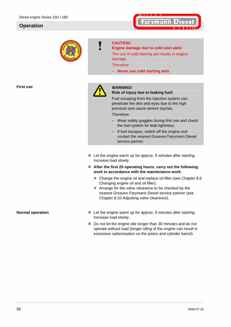
Example of the key switch positions: 0 Electrical system switched off. Key can be removed.
I Electrical system switched on. Operating position
II Electrical system switched on. Starting position
Starting engine
Fig. 36
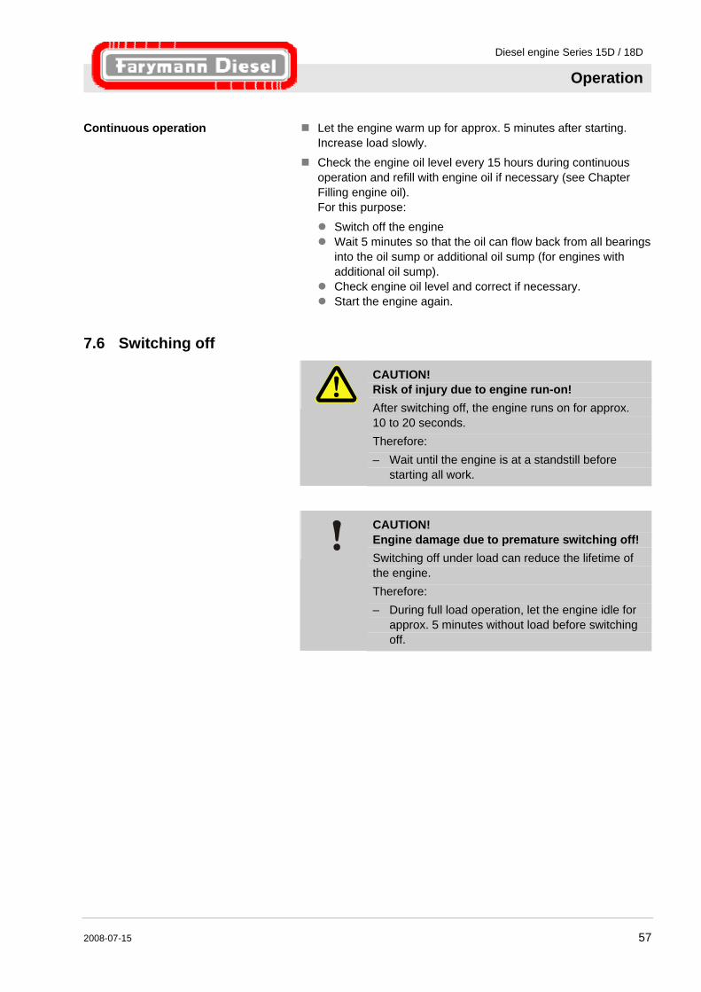
1. If the engine is cold, put the speed adjustment lever (1) in the increased idle speed position (3). If the engine is warm, put the speed adjustment lever (1) in the position (2) (depending on the application of the engine).
2. Turn key e.g. to position I. Any existing indicator lamps from the machine must light afterwards (e.g. oil check, battery charge check, etc.).
3. Press in the key, turn as far as position II and release immediately after the engine starts.
NOTE! If the engine does not start, the battery voltage can be too low. Charge the battery or replace it if necessary.
7.5 Operation
CAUTION! Engine damage due to incorrect operation! The lifetime of the engine can be reduced due to incorrect operation. Therefore: – Strictly observe the following instructions for first
use, normal operation and continuous operation.
Diesel engine Series 15D / 18D
Operation
56 2008-07-15
CAUTION! Engine damage due to cold start aids! The use of cold starting aid results in engine damage. Therefore: – Never use cold starting aids.
First use
WARNING! Risk of injury due to leaking fuel! Fuel escaping from the injection system can penetrate the skin and eyes due to the high pressure and cause severe injuries. Therefore: – Wear safety goggles during first use and check
the fuel system for leak tightness. – If fuel escapes, switch off the engine and
contact the nearest Greaves Farymann Diesel service partner.
Let the engine warm up for approx. 5 minutes after starting.
Increase load slowly.
After the first 25 operating hours, carry out the following work in accordance with the maintenance work:
Change the engine oil and replace oil filter (see Chapter 8.6 Changing engine oil and oil filter).
Arrange for the valve clearance to be checked by the nearest Greaves Farymann Diesel service partner (see Chapter 8.10 Adjusting valve clearance).
Normal operation Let the engine warm up for approx. 5 minutes after starting. Increase load slowly.
Do not let the engine idle longer than 30 minutes and do not operate without load (longer idling of the engine can result in excessive carbonisation on the piston and cylinder barrel).
Diesel engine Series 15D / 18D
Operation
2008-07-15 57
Continuous operation Let the engine warm up for approx. 5 minutes after starting. Increase load slowly.
Check the engine oil level every 15 hours during continuous operation and refill with engine oil if necessary (see Chapter Filling engine oil). For this purpose:
Switch off the engine Wait 5 minutes so that the oil can flow back from all bearings
into the oil sump or additional oil sump (for engines with additional oil sump).
Check engine oil level and correct if necessary. Start the engine again.
7.6 Switching off
CAUTION! Risk of injury due to engine run-on! After switching off, the engine runs on for approx. 10 to 20 seconds. Therefore: – Wait until the engine is at a standstill before
starting all work.
CAUTION! Engine damage due to premature switching off! Switching off under load can reduce the lifetime of the engine. Therefore: – During full load operation, let the engine idle for
approx. 5 minutes without load before switching off.
Diesel engine Series 15D / 18D
Operation
58 2008-07-15
7.6.1 Engine without electric starter
Fig. 37
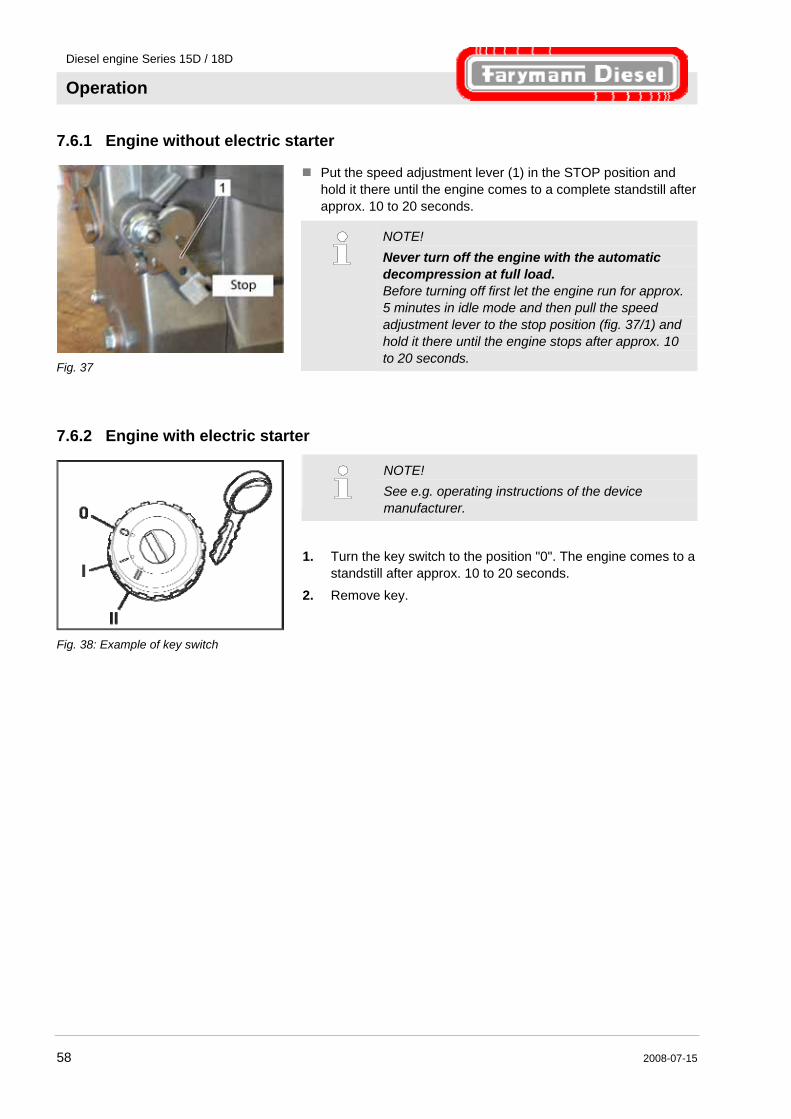
Put the speed adjustment lever (1) in the STOP position and hold it there until the engine comes to a complete standstill after approx. 10 to 20 seconds.
NOTE! Never turn off the engine with the automatic decompression at full load. Before turning off first let the engine run for approx. 5 minutes in idle mode and then pull the speed adjustment lever to the stop position (fig. 37/1) and hold it there until the engine stops after approx. 10 to 20 seconds.
7.6.2 Engine with electric starter
Fig. 38: Example of key switch
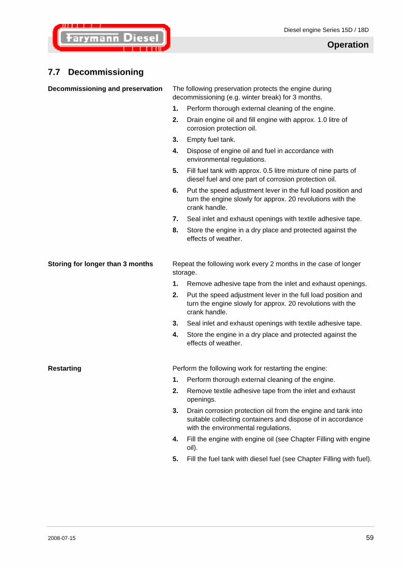
NOTE! See e.g. operating instructions of the device manufacturer.
1. Turn the key switch to the position "0". The engine comes to a
standstill after approx. 10 to 20 seconds. 2. Remove key.
Diesel engine Series 15D / 18D
Operation
2008-07-15 59
7.7 Decommissioning
Decommissioning and preservation The following preservation protects the engine during decommissioning (e.g. winter break) for 3 months. 1. Perform thorough external cleaning of the engine.
2. Drain engine oil and fill engine with approx. 1.0 litre of corrosion protection oil.
3. Empty fuel tank.
4. Dispose of engine oil and fuel in accordance with environmental regulations.
5. Fill fuel tank with approx. 0.5 litre mixture of nine parts of diesel fuel and one part of corrosion protection oil.
6. Put the speed adjustment lever in the full load position and turn the engine slowly for approx. 20 revolutions with the crank handle.
7. Seal inlet and exhaust openings with textile adhesive tape.
8. Store the engine in a dry place and protected against the effects of weather.
Storing for longer than 3 months Repeat the following work every 2 months in the case of longer storage.
1. Remove adhesive tape from the inlet and exhaust openings. 2. Put the speed adjustment lever in the full load position and
turn the engine slowly for approx. 20 revolutions with the crank handle.
3. Seal inlet and exhaust openings with textile adhesive tape.
4. Store the engine in a dry place and protected against the effects of weather.
Restarting Perform the following work for restarting the engine:
1. Perform thorough external cleaning of the engine. 2. Remove textile adhesive tape from the inlet and exhaust
openings. 3. Drain corrosion protection oil from the engine and tank into
suitable collecting containers and dispose of in accordance with the environmental regulations.
4. Fill the engine with engine oil (see Chapter Filling with engine oil).
5. Fill the fuel tank with diesel fuel (see Chapter Filling with fuel).
Diesel engine Series 15D / 18D
Maintenance
60 2008-07-15
8 Maintenance
8.1 Safety
Maintenance work not carried out correctly
WARNING! Risk of injury due to incorrectly carried out maintenance work! Improper maintenance can result in severe personal injuries or material damage. Therefore: – Always undertake maintenance work when the
engine is switched off. – Ensure there is sufficient installation clearance
before starting work. – Ensure tidiness and cleanliness at the
workplace. Loose components and tools lying around or on top of each other are sources of accidents.
– Only perform maintenance work using commercially available tools and special tools. Incorrect or damaged tools can result in injuries.
Engine oil and fuel
WARNING! Danger of fire due to fuel and engine oil! Oil and fuel vapours can ignite on contact with ignition sources. Therefore: – No naked flames during work on the engine. – Do not smoke. – Remove oil and fuel residues from the engine
and floor.
CAUTION! Danger of poisoning due to fuel and engine oil! Contact with engine oil and fuel can result in damage to health. Therefore: – Avoid skin contact with engine oil and fuel. – Remove oil and fuel splashes from the skin
immediately. – Do not inhale oil and fuel vapours.
Diesel engine Series 15D / 18D
Maintenance
2008-07-15 61
Personnel The maintenance work described here can be performed by the operator unless otherwise indicated.
Other maintenance work must only be performed by specially trained qualified personnel or by specialist workshops (Greaves Farymann Diesel service partners). This particularly applies to work on the valve adjustment, diesel injection system and for the engine repair.
Personal protective equipment Wear the following protective equipment for all maintenance work: Protective clothing Safety footwear
NOTE! Protective equipment which must be worn for certain work is specially pointed out in the warnings of this chapter.
NOTE! Independent repair and adjustment work on the engine beyond a very limited scope is forbidden for safety reasons. Improper work on components relevant for safety endangers you and others. This particularly applies to work on the valve adjustment, diesel injection system and for the engine repair. Do not tighten cylinder head nuts! In the case of use where there is an excessive occurrence of dust, shorten the maintenance intervals by at least half. In the case of low operating time, the engine oil and oil filter must be replaced at least every 12 months irrespective of the actual operating hours. Only use original Greaves Farymann Diesel spare parts.
Diesel engine Series 15D / 18D
Maintenance
62 2008-07-15
8.2 Maintenance plan The various tasks are listed in the maintenance plan.
The maintenance intervals must be complied with as follows: daily before every start-up
after 25 operating hours every 250 operating hours
every 500 operating hours
NOTE! The maintenance interval for 500 operating hours includes all the work for the interval of 250 operating hours.
Diesel engine Series 15D / 18D
Maintenance
2008-07-15 63
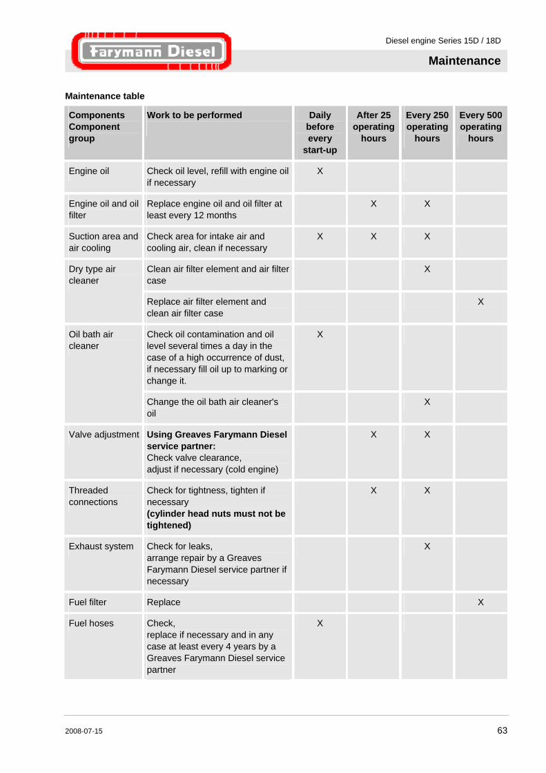
Maintenance table
Components Component group
Work to be performed
Daily before every
start-up
After 25 operating
hours
Every 250 operating
hours
Every 500 operating
hours
Engine oil Check oil level, refill with engine oil if necessary
X
Engine oil and oil filter
Replace engine oil and oil filter at least every 12 months
X X
Suction area and air cooling
Check area for intake air and cooling air, clean if necessary
X X X
Clean air filter element and air filter case
X Dry type air cleaner
Replace air filter element and clean air filter case
X
Check oil contamination and oil level several times a day in the case of a high occurrence of dust, if necessary fill oil up to marking or change it.
X Oil bath air cleaner
Change the oil bath air cleaner's oil
X
Valve adjustment Using Greaves Farymann Diesel service partner: Check valve clearance, adjust if necessary (cold engine)
X X
Threaded connections
Check for tightness, tighten if necessary (cylinder head nuts must not be tightened)
X X
Exhaust system Check for leaks, arrange repair by a Greaves Farymann Diesel service partner if necessary
X
Fuel filter Replace X
Fuel hoses Check, replace if necessary and in any case at least every 4 years by a Greaves Farymann Diesel service partner
X
Diesel engine Series 15D / 18D
Maintenance
64 2008-07-15
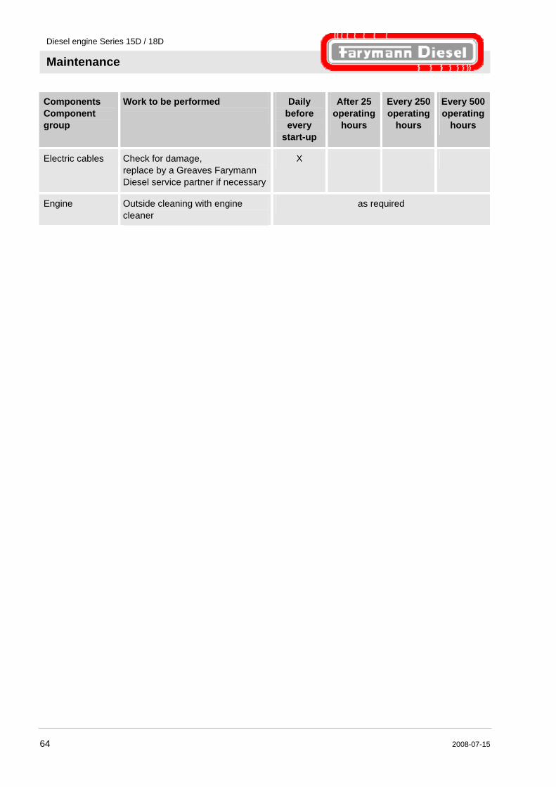
Components Component group
Work to be performed
Daily before every
start-up
After 25 operating
hours
Every 250 operating
hours
Every 500 operating
hours
Electric cables Check for damage, replace by a Greaves Farymann Diesel service partner if necessary
X
Engine Outside cleaning with engine cleaner
as required
Diesel engine Series 15D / 18D
Maintenance
2008-07-15 65
Maintenance for special conditions
CAUTION! Reduced maintenance intervals in the case of special conditions! Additional maintenance is necessary in the case of special operating conditions in order to maintain the lifetime of the engine. Therefore: – Observe the following points.
Excessive occurrence of dust In the case of use where there is an excessive occurrence of dust, the maintenance intervals must be at least halved.
Low operating time In the case of low operating time, the engine oil and oil filter must be replaced at least every 12 months irrespective of the actual operating hours.
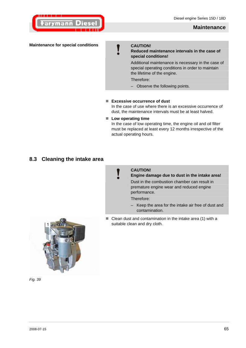
8.3 Cleaning the intake area
CAUTION! Engine damage due to dust in the intake area! Dust in the combustion chamber can result in premature engine wear and reduced engine performance. Therefore: – Keep the area for the intake air free of dust and
contamination.
Fig. 39
Clean dust and contamination in the intake area (1) with a suitable clean and dry cloth.
Diesel engine Series 15D / 18D
Maintenance
66 2008-07-15
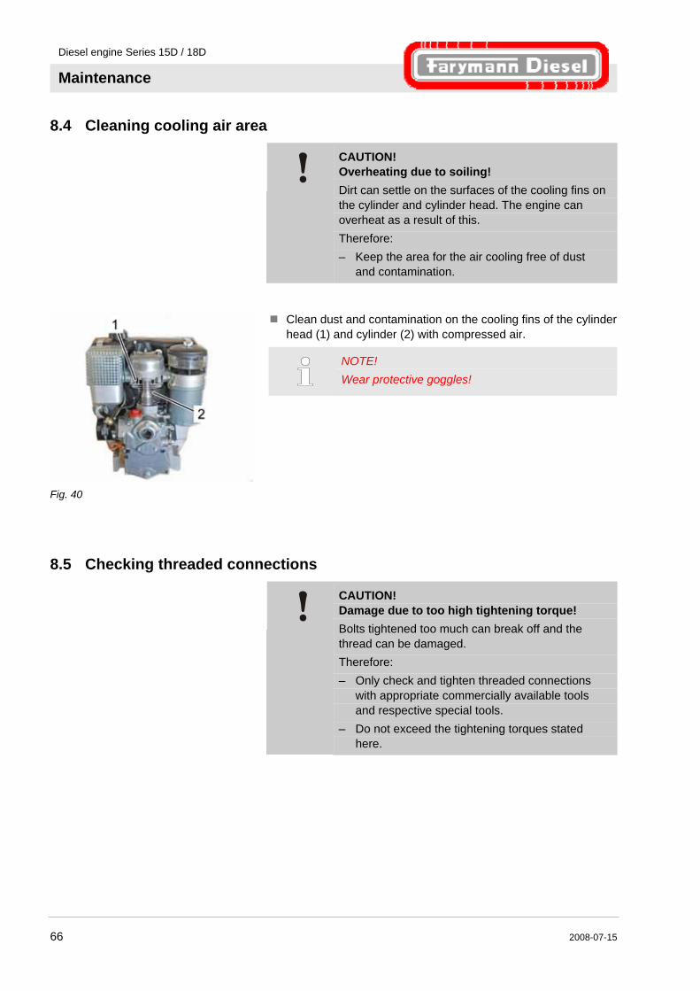
8.4 Cleaning cooling air area
CAUTION! Overheating due to soiling! Dirt can settle on the surfaces of the cooling fins on the cylinder and cylinder head. The engine can overheat as a result of this. Therefore: – Keep the area for the air cooling free of dust
and contamination.
Fig. 40
Clean dust and contamination on the cooling fins of the cylinder head (1) and cylinder (2) with compressed air.
NOTE! Wear protective goggles!
8.5 Checking threaded connections
CAUTION! Damage due to too high tightening torque! Bolts tightened too much can break off and the thread can be damaged. Therefore: – Only check and tighten threaded connections
with appropriate commercially available tools and respective special tools.
– Do not exceed the tightening torques stated here.
Diesel engine Series 15D / 18D
Maintenance
2008-07-15 67
CAUTION! Cylinder head nuts must not be tightened! Therefore: – Do not tighten cylinder head nuts without
authorisation. – Arrange for work on the cylinder head to be
carried out by a Greaves Farymann Diesel service partner.
Tightening torques
Threaded connection relevant for safety Tightening torque Nm
High pressure line of the injection nozzle holder 25
Mounting of the fuel filter 10
Wing nut of sealing cap of the air filter case After cleaning or replacing the air filter only tighten the wing
nut of the air filter case by hand.
Exhaust silencer bolts 10
Oil filter Only tighten oil filter by hand.
Valve cover 8–12
Oil drain plug 12
Diesel engine Series 15D / 18D
Maintenance
68 2008-07-15
8.6 Changing engine oil
NOTE! Only change engine oil when the engine is at a standstill and at operating temperature. Always replace engine oil and oil filter together.
8.6.1 Version with oil drain plug
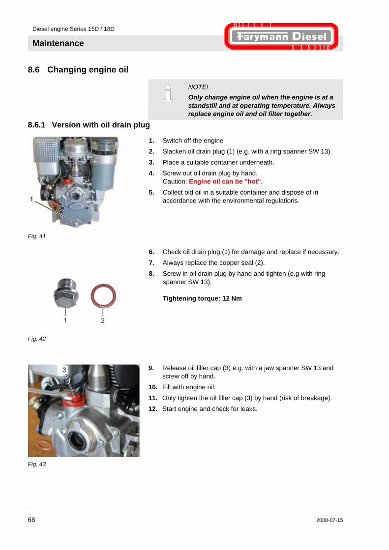
Fig. 41
1. Switch off the engine 2. Slacken oil drain plug (1) (e.g. with a ring spanner SW 13).
3. Place a suitable container underneath. 4. Screw out oil drain plug by hand.
Caution: Engine oil can be "hot". 5. Collect old oil in a suitable container and dispose of in
accordance with the environmental regulations.
Fig. 42
6. Check oil drain plug (1) for damage and replace if necessary. 7. Always replace the copper seal (2).
8. Screw in oil drain plug by hand and tighten (e.g with ring spanner SW 13). Tightening torque: 12 Nm
Fig. 43
9. Release oil filler cap (3) e.g. with a jaw spanner SW 13 and screw off by hand.
10. Fill with engine oil.
11. Only tighten the oil filler cap (3) by hand (risk of breakage). 12. Start engine and check for leaks.
Diesel engine Series 15D / 18D
Maintenance
2008-07-15 69
8.6.2 Version with oil drain valve
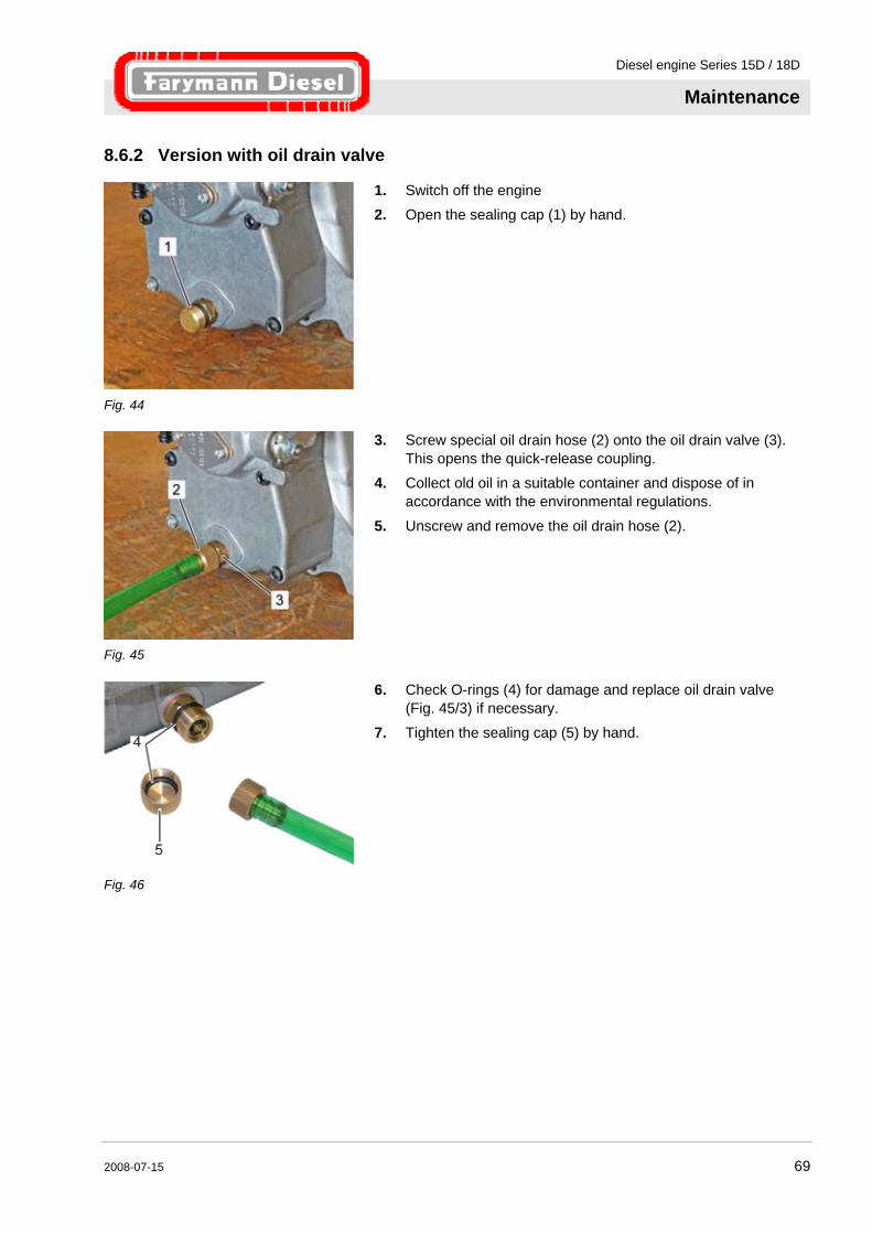
Fig. 44
1. Switch off the engine 2. Open the sealing cap (1) by hand.
Fig. 45
3. Screw special oil drain hose (2) onto the oil drain valve (3). This opens the quick-release coupling.
4. Collect old oil in a suitable container and dispose of in accordance with the environmental regulations.
5. Unscrew and remove the oil drain hose (2).
Fig. 46
6. Check O-rings (4) for damage and replace oil drain valve (Fig. 45/3) if necessary.
7. Tighten the sealing cap (5) by hand.
Diesel engine Series 15D / 18D
Maintenance
70 2008-07-15
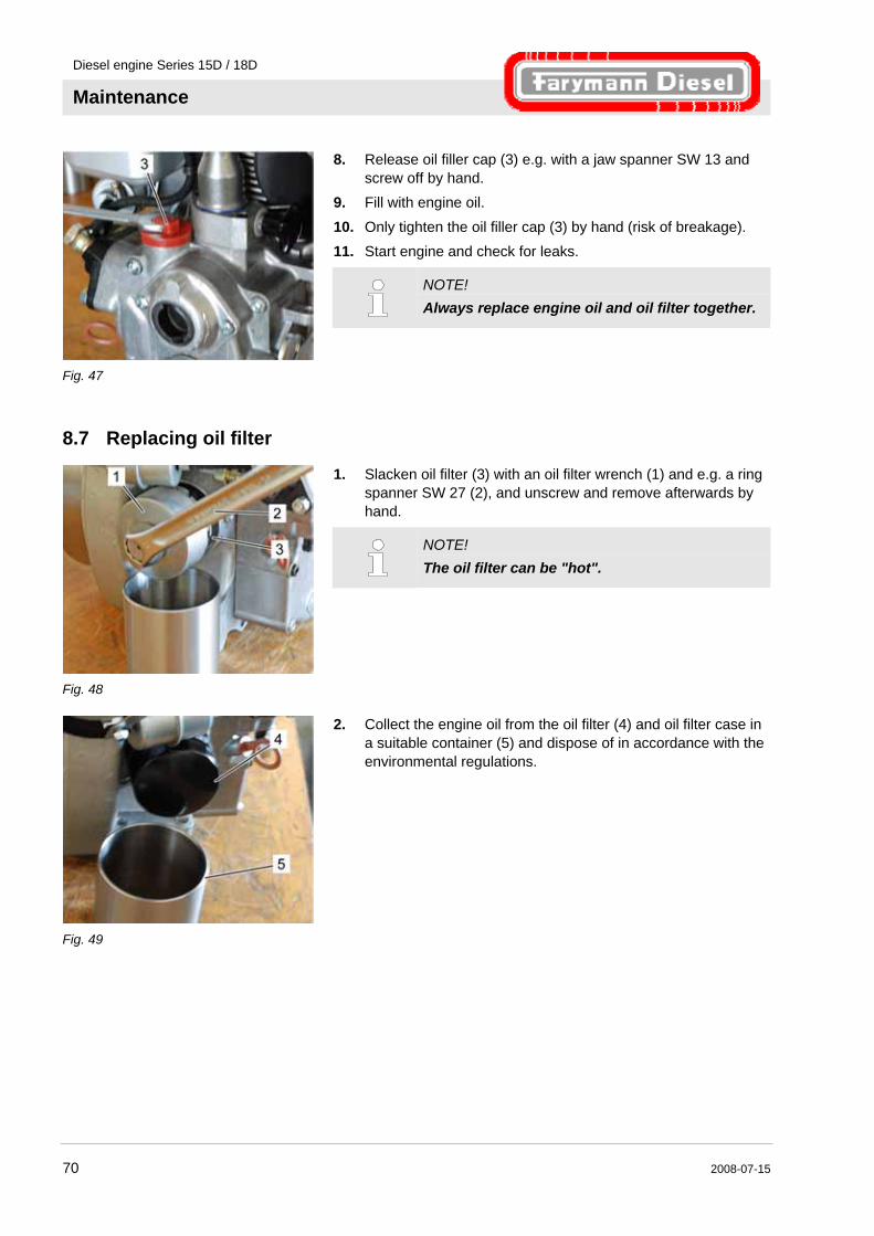
Fig. 47
8. Release oil filler cap (3) e.g. with a jaw spanner SW 13 and screw off by hand.
9. Fill with engine oil.
10. Only tighten the oil filler cap (3) by hand (risk of breakage). 11. Start engine and check for leaks.
NOTE! Always replace engine oil and oil filter together.
8.7 Replacing oil filter
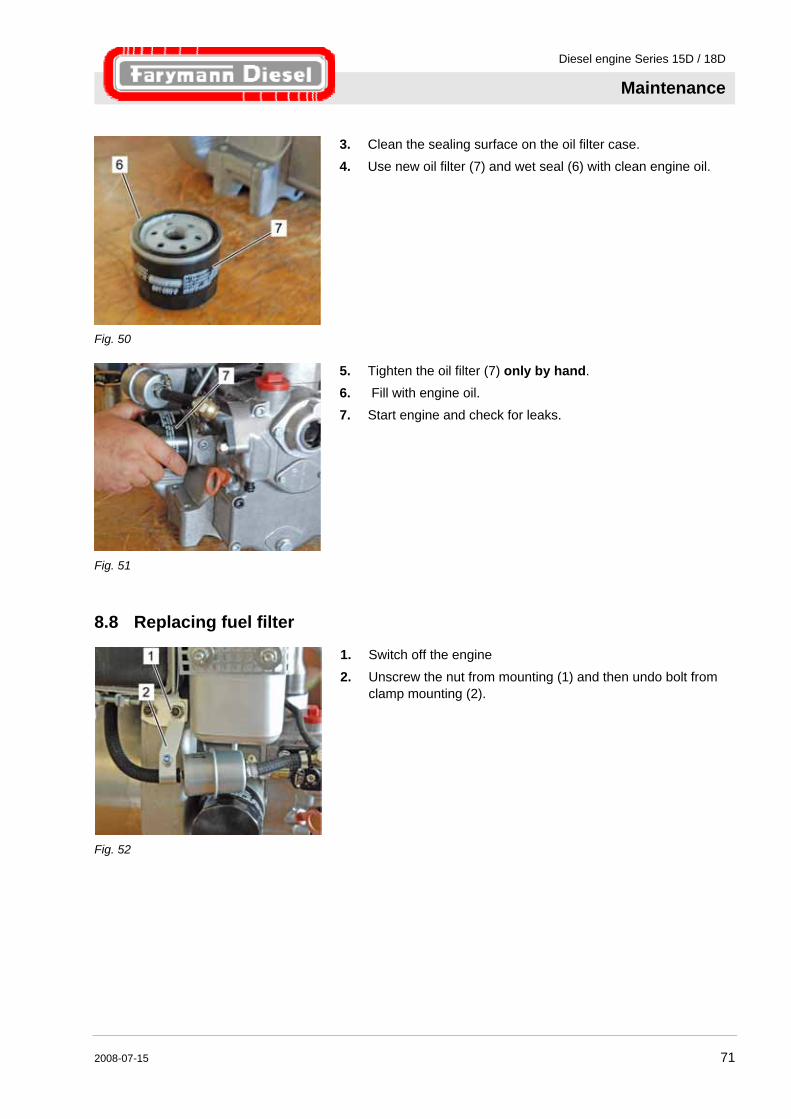
Fig. 48
1. Slacken oil filter (3) with an oil filter wrench (1) and e.g. a ring spanner SW 27 (2), and unscrew and remove afterwards by hand.
NOTE! The oil filter can be "hot".
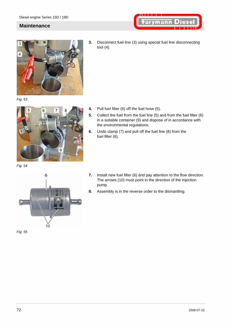
Fig. 49
2. Collect the engine oil from the oil filter (4) and oil filter case in a suitable container (5) and dispose of in accordance with the environmental regulations.
Diesel engine Series 15D / 18D
Maintenance
2008-07-15 71
Fig. 50
3. Clean the sealing surface on the oil filter case. 4. Use new oil filter (7) and wet seal (6) with clean engine oil.
Fig. 51
5. Tighten the oil filter (7) only by hand. 6. Fill with engine oil. 7. Start engine and check for leaks.
8.8 Replacing fuel filter
Fig. 52
1. Switch off the engine
2. Unscrew the nut from mounting (1) and then undo bolt from clamp mounting (2).
Diesel engine Series 15D / 18D
Maintenance
72 2008-07-15
Fig. 53
3. Disconnect fuel line (3) using special fuel line disconnecting tool (4).
Fig. 54
4. Pull fuel filter (6) off the fuel hose (5). 5. Collect the fuel from the fuel line (5) and from the fuel filter (6)
in a suitable container (9) and dispose of in accordance with the environmental regulations.
6. Undo clamp (7) and pull off the fuel line (8) from the fuel filter (6).
Fig. 55
7. Install new fuel filter (6) and pay attention to the flow direction. The arrows (10) must point in the direction of the injection pump.
8. Assembly is in the reverse order to the dismantling.
Diesel engine Series 15D / 18D
Maintenance
2008-07-15 73
Fig. 56
9. Tighten the nut (1) of the mounting (2) on the engine. Tightening torque: 10 Nm
10. Start engine and check the fuel system for leaks.
c
8.9 Replacing air filter
CAUTION! Engine damage due to use of non-original air filter! Unfiltered air can result in rough engine running and engine damage. A dusty air filter reduces the engine power and increases the fuel consumption. Therefore: – Do not operate the engine without the air filter. – Clean or replace air filter according to the
maintenance plan.
8.9.1 Dry type air cleaner (standard engine)
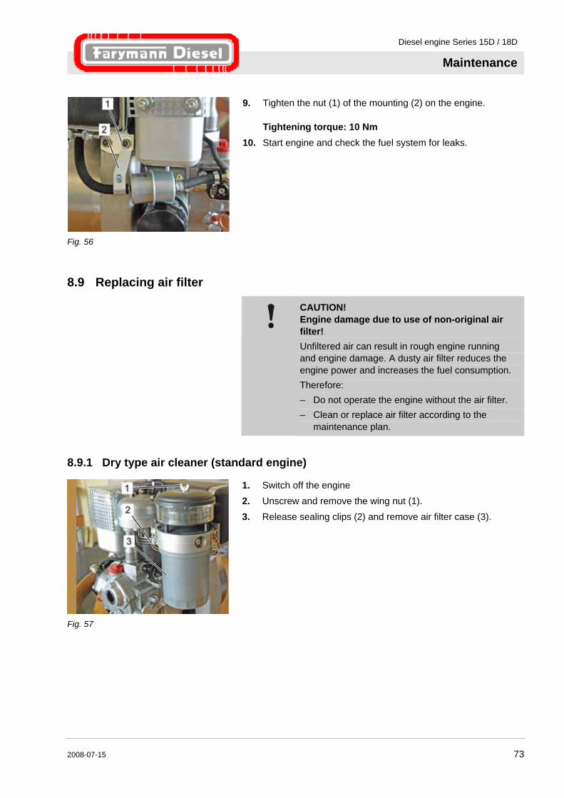
Fig. 57
1. Switch off the engine 2. Unscrew and remove the wing nut (1). 3. Release sealing clips (2) and remove air filter case (3).
Diesel engine Series 15D / 18D
Maintenance
74 2008-07-15
Fig. 58
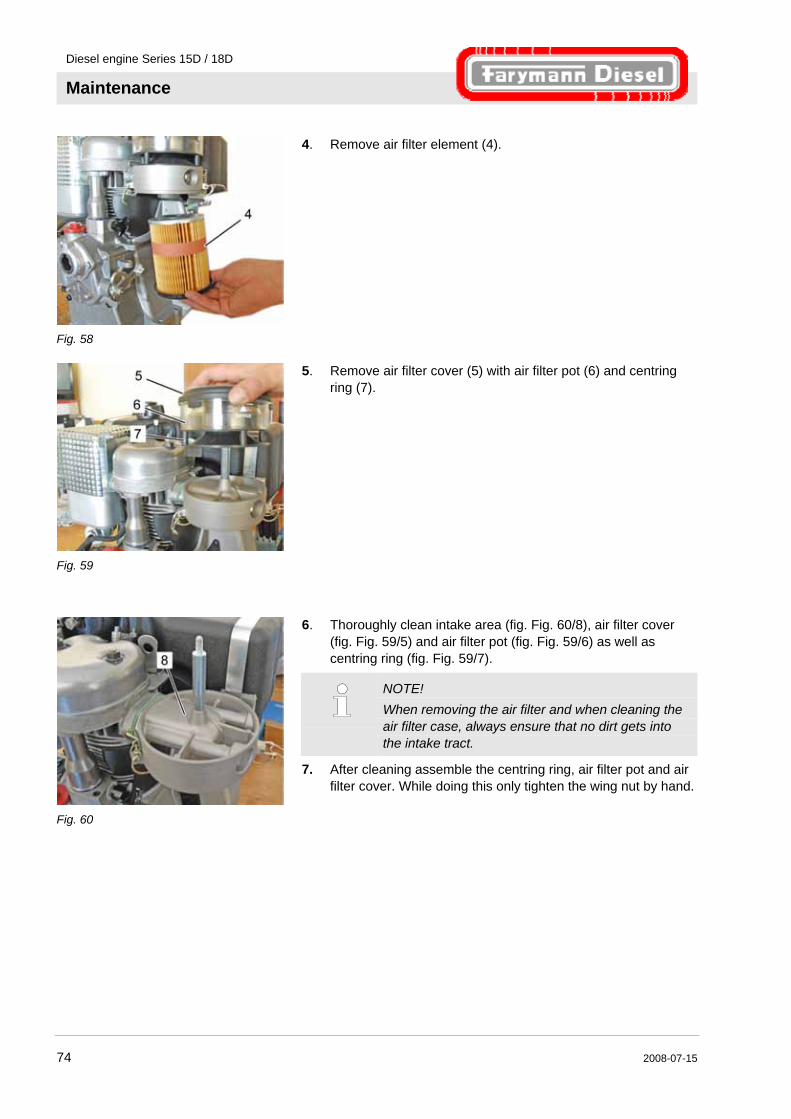
4. Remove air filter element (4).
Fig. 59
5. Remove air filter cover (5) with air filter pot (6) and centring ring (7).
Fig. 60
6. Thoroughly clean intake area (fig. Fig. 60/8), air filter cover (fig. Fig. 59/5) and air filter pot (fig. Fig. 59/6) as well as centring ring (fig. Fig. 59/7).
NOTE! When removing the air filter and when cleaning the air filter case, always ensure that no dirt gets into the intake tract.
7. After cleaning assemble the centring ring, air filter pot and air filter cover. While doing this only tighten the wing nut by hand.

Diesel engine Series 15D / 18D
Maintenance
2008-07-15 75
Fig. 61
8. Install new air filter element (4).
Fig. 62
9. Position air filter case (2) straight, in the process pay attention to correct seating, and close sealing clips (1).
8.9.2 Oil bath air cleaner (standard engine)
Fig. 63
NOTE! Check oil contamination and oil level several times a day in the case of a high occurrence of dust, if necessary fill oil up to marking or change it (see maintenance plan).
1. Open fasteners (2) and remove oil container (1). 2. Remove contaminated oil and sludge from oil container.
Collect old oil and dispose of it in accordance with environmental regulations.
3. Clean the oil container thoroughly.
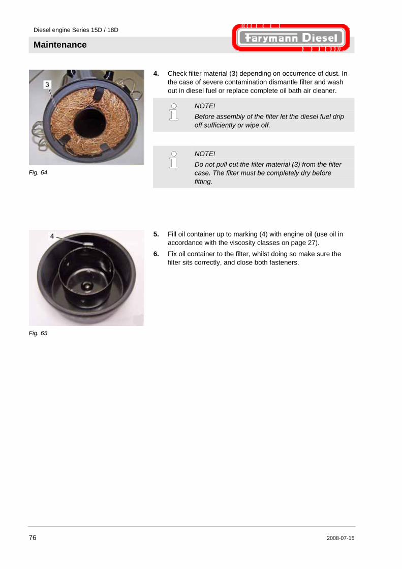
Diesel engine Series 15D / 18D
Maintenance
76 2008-07-15
Fig. 64
4. Check filter material (3) depending on occurrence of dust. In the case of severe contamination dismantle filter and wash out in diesel fuel or replace complete oil bath air cleaner.
NOTE! Before assembly of the filter let the diesel fuel drip off sufficiently or wipe off.
NOTE! Do not pull out the filter material (3) from the filter case. The filter must be completely dry before fitting.
Fig. 65
5. Fill oil container up to marking (4) with engine oil (use oil in accordance with the viscosity classes on page 27).
6. Fix oil container to the filter, whilst doing so make sure the filter sits correctly, and close both fasteners.
Diesel engine Series 15D / 18D
Maintenance
2008-07-15 77
8.10 Adjusting valve clearance
Safety
WARNING! Risk of injury due to starting the engine! The engine can be accidentally started when adjusting the valve clearance and thereby cause severe injuries. Therefore: – Disconnect the high pressure line on the
injection nozzle holder before starting work.
Personnel This work must only be carried out by trained specialist personnel. In the absence of the required qualifications, arrange for the work to be carried out by a Greaves Farymann Diesel service partner.
Prerequisites Only check and adjust the valve clearance when the engine is cold (less than 35 °C).
Settings Exhaust valve 0.1 mm Intake valve 0.1 mm
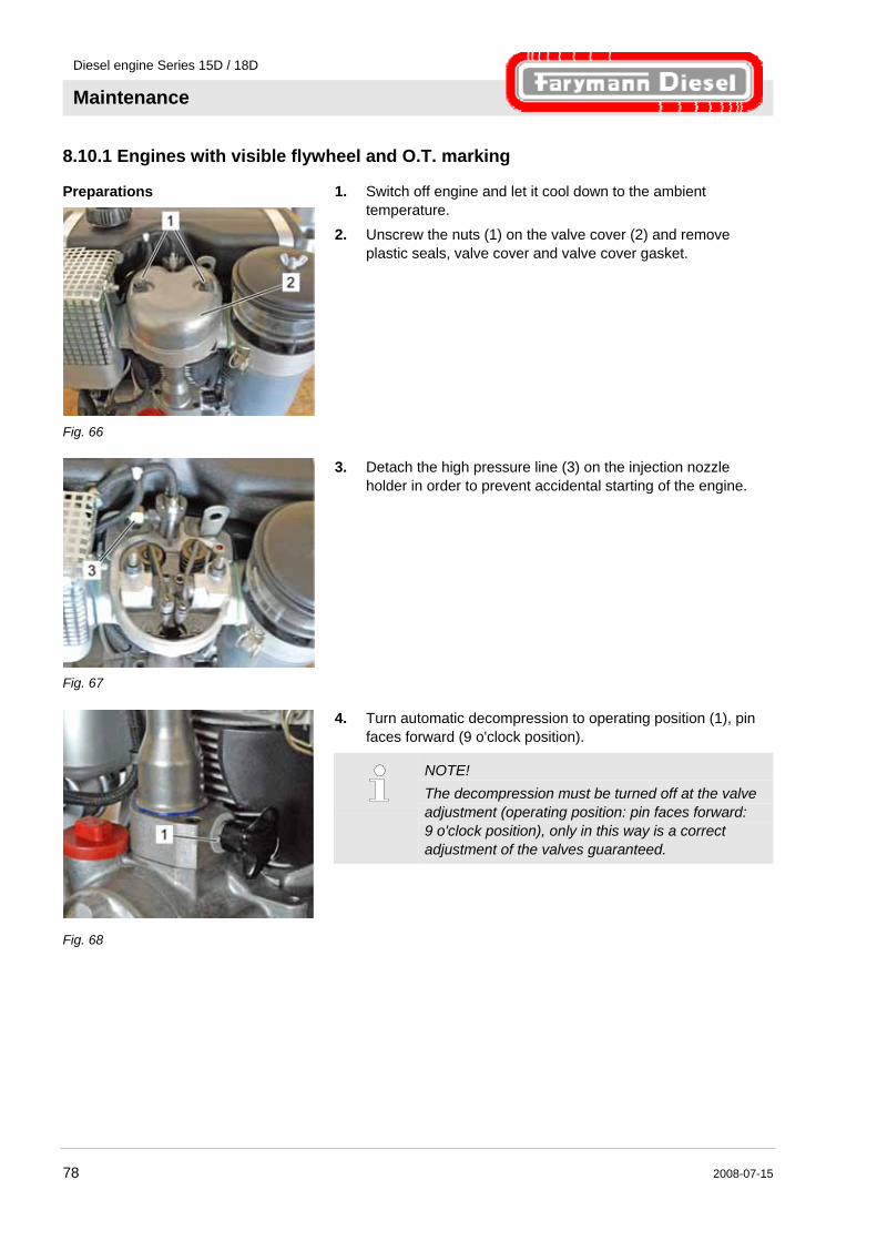
Diesel engine Series 15D / 18D
Maintenance
78 2008-07-15
8.10.1 Engines with visible flywheel and O.T. marking
Preparations
Fig. 66
1. Switch off engine and let it cool down to the ambient temperature.
2. Unscrew the nuts (1) on the valve cover (2) and remove plastic seals, valve cover and valve cover gasket.
Fig. 67
3. Detach the high pressure line (3) on the injection nozzle holder in order to prevent accidental starting of the engine.
Fig. 68
4. Turn automatic decompression to operating position (1), pin faces forward (9 o'clock position).
NOTE! The decompression must be turned off at the valve adjustment (operating position: pin faces forward: 9 o'clock position), only in this way is a correct adjustment of the valves guaranteed.
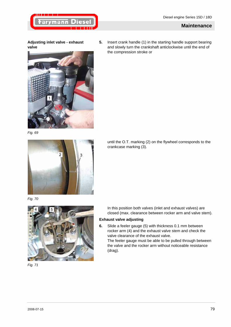
Diesel engine Series 15D / 18D
Maintenance
2008-07-15 79
Adjusting inlet valve - exhaust valve
Fig. 69
5. Insert crank handle (1) in the starting handle support bearing and slowly turn the crankshaft anticlockwise until the end of the compression stroke or
Fig. 70
until the O.T. marking (2) on the flywheel corresponds to the crankcase marking (3).
Fig. 71
In this position both valves (inlet and exhaust valves) are closed (max. clearance between rocker arm and valve stem).
Exhaust valve adjusting 6. Slide a feeler gauge (5) with thickness 0.1 mm between
rocker arm (4) and the exhaust valve stem and check the valve clearance of the exhaust valve. The feeler gauge must be able to be pulled through between the valve and the rocker arm without noticeable resistance (drag).

Diesel engine Series 15D / 18D
Maintenance
80 2008-07-15
Fig. 72
7. If the clearance is too large or too small, undo the lock nut (6) and adjust the clearance with the adjusting screw (7). The feeler gauge must be able to be pulled through without noticeable resistance (drag).
8. Hold the adjusting screw in place with a screwdriver and tighten the lock nut.
9. Check the valve clearance again.
Fig. 73
Inlet valve adjusting 10. Adjusting the inlet valve is carried out in exactly the same way
as for the exhaust valve (see Fig. 71).
Fig. 74
11. Tighten the high pressure line (3) on the injection nozzle holder.
Tightening torque 25 Nm 12. Replace valve cover gasket.

Diesel engine Series 15D / 18D
Maintenance
2008-07-15 81
Fig. 75
13. Install valve cover (2) using two plastic seals. 14. Tighten both nuts (1) of the valve cover (2).
Tightening torque 8-12 Nm
NOTE! Always replace the valve cover gasket and the two plastic seals under the nuts of the valve cover.
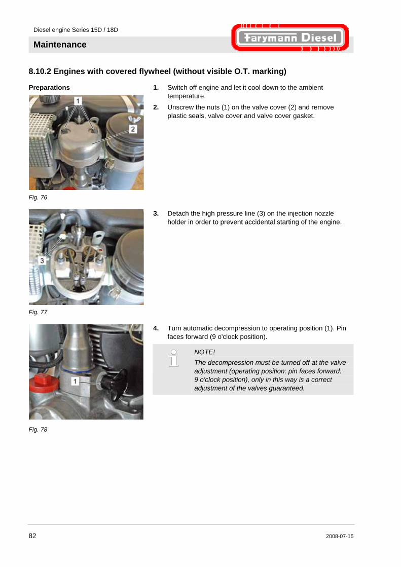
Diesel engine Series 15D / 18D
Maintenance
82 2008-07-15
8.10.2 Engines with covered flywheel (without visible O.T. marking)
Preparations
Fig. 76
1. Switch off engine and let it cool down to the ambient temperature.
2. Unscrew the nuts (1) on the valve cover (2) and remove plastic seals, valve cover and valve cover gasket.
Fig. 77
3. Detach the high pressure line (3) on the injection nozzle holder in order to prevent accidental starting of the engine.
Fig. 78
4. Turn automatic decompression to operating position (1). Pin faces forward (9 o'clock position).
NOTE! The decompression must be turned off at the valve adjustment (operating position: pin faces forward: 9 o'clock position), only in this way is a correct adjustment of the valves guaranteed.

Diesel engine Series 15D / 18D
Maintenance
2008-07-15 83
Adjusting exhaust valve
Fig. 79
5. Insert crank handle (1) into the starting handle support bearing and slowly turn the crankshaft anticlockwise until the inlet valve's spring is pushed down completely (inlet valve is now fully open).
Fig. 80
6. Slide a feeler gauge (5) with thickness 0.1 mm between rocker arm (4) and the exhaust valve stem and check the valve clearance of the exhaust valve. The feeler gauge must be able to be pulled through without noticeable resistance (drag).
Fig. 81
7. If the clearance is too large or too small, undo the lock nut (6) and adjust the clearance with the adjusting screw (7). The feeler gauge must be able to be pulled through without noticeable resistance (drag).
8. Hold the adjusting screw in place with a screwdriver and tighten the lock nut.
9. Check the valve clearance again.
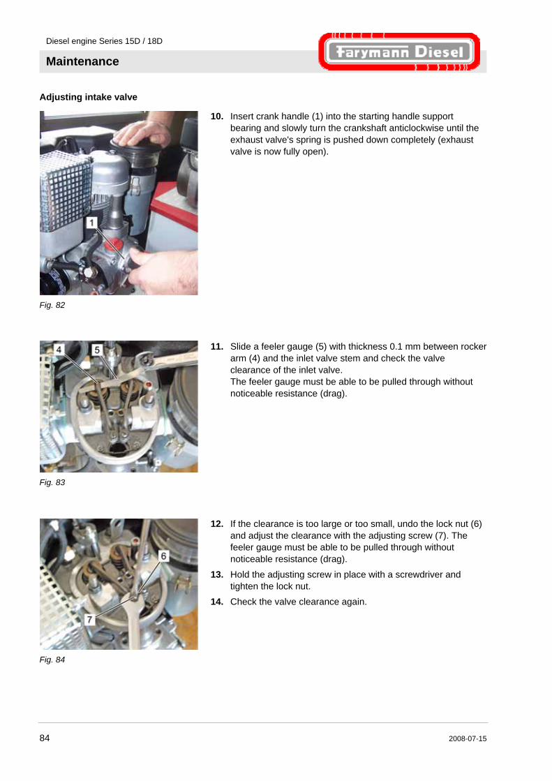
Diesel engine Series 15D / 18D
Maintenance
84 2008-07-15
Adjusting intake valve
Fig. 82
10. Insert crank handle (1) into the starting handle support bearing and slowly turn the crankshaft anticlockwise until the exhaust valve's spring is pushed down completely (exhaust valve is now fully open).
Fig. 83
11. Slide a feeler gauge (5) with thickness 0.1 mm between rocker arm (4) and the inlet valve stem and check the valve clearance of the inlet valve. The feeler gauge must be able to be pulled through without noticeable resistance (drag).
Fig. 84
12. If the clearance is too large or too small, undo the lock nut (6) and adjust the clearance with the adjusting screw (7). The feeler gauge must be able to be pulled through without noticeable resistance (drag).
13. Hold the adjusting screw in place with a screwdriver and tighten the lock nut.
14. Check the valve clearance again.
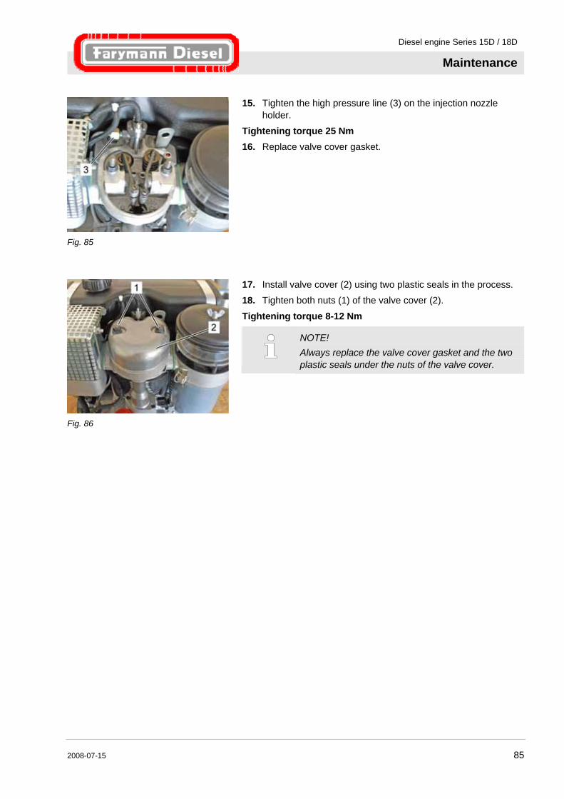
Diesel engine Series 15D / 18D
Maintenance
2008-07-15 85
Fig. 85
15. Tighten the high pressure line (3) on the injection nozzle holder.
Tightening torque 25 Nm 16. Replace valve cover gasket.
Fig. 86
17. Install valve cover (2) using two plastic seals in the process. 18. Tighten both nuts (1) of the valve cover (2).
Tightening torque 8-12 Nm
NOTE! Always replace the valve cover gasket and the two plastic seals under the nuts of the valve cover.

Diesel engine Series 15D / 18D
Faults
86 2008-07-15
9 Faults Possible causes of faults and the work for rectifying them are described in the following chapter. In the case of increasingly occurring faults, reduce the maintenance intervals in accordance with the actual load.
In the case of faults which cannot be rectified using the following information, contact the nearest Greaves Farymann Diesel service partner or the manufacturer.
9.1 Safety
Personnel The work described here for fault clearance can be performed by the operator unless otherwise indicated.
Some work must only be performed by a Greaves Farymann Diesel service partner; this is specially pointed out in the description of the individual faults.
Personal protective equipment Wear the following protective equipment for all maintenance work: Protective clothing
Safety footwear
NOTE! Protective equipment which must be worn for certain work is specially pointed out in the warnings of this chapter.
Diesel engine Series 15D / 18D
Faults
2008-07-15 87
Improper fault clearance
WARNING! Risk of injury due to improper fault clearance! Improper fault clearance can result in severe personal injuries or material damage. Therefore: – Ensure there is sufficient installation clearance
before starting work. – Ensure tidiness and cleanliness at the
workplace! Loose components and tools lying around or on top of each other cause accidents.
– If parts have been removed, pay attention to correct assembly, reinstall all fixing elements and comply with the tightening torques for threaded connections.
Engine oil and fuel
WARNING! Danger of fire due to fuel and engine oil! Oil and fuel vapours can ignite on contact with ignition sources. Therefore: – No naked flames during work on the engine. – Do not smoke. – Remove oil and fuel residues from the engine
and floor.
CAUTION! Danger of poisoning due to fuel and engine oil! Contact with engine oil and fuel can result in damage to health. Therefore: – Avoid skin contact with engine oil and fuel. – Remove oil and fuel splashes from the skin
immediately. – Do not inhale oil and fuel vapours.
Diesel engine Series 15D / 18D
Faults
88 2008-07-15
Procedure for faults The basic rule is: 1. Stop the engine immediately in the case of faults which
represent an immediate danger for persons or property.
2. Determine the cause of the fault. 3. Inform the responsible person at the usage location about the
fault.
4. Arrange for rectification by a Greaves Farymann Diesel service partner or yourself depending on the type of the fault.
NOTE! The fault table listed below gives information about who is authorised for rectification of the fault.
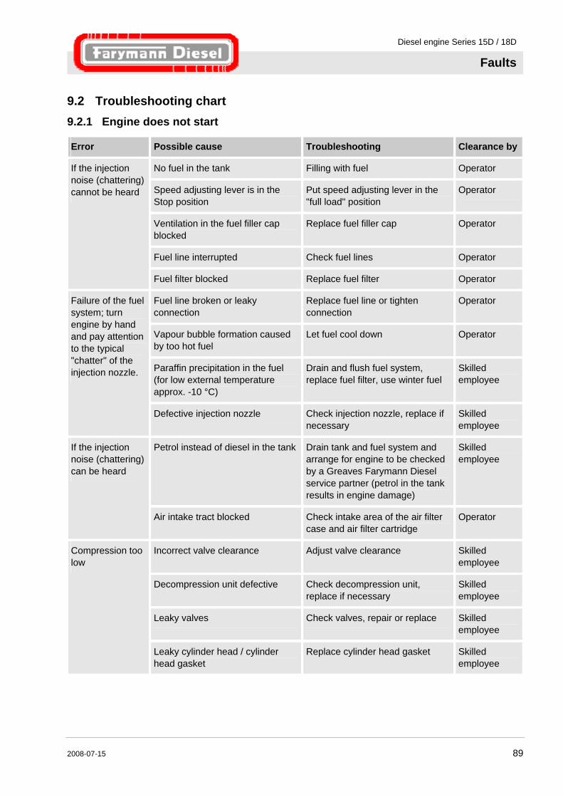
Diesel engine Series 15D / 18D
Faults
2008-07-15 89
9.2 Troubleshooting chart
9.2.1 Engine does not start
Error Possible cause Troubleshooting Clearance by
No fuel in the tank Filling with fuel Operator
Speed adjusting lever is in the Stop position
Put speed adjusting lever in the "full load" position
Operator
Ventilation in the fuel filler cap blocked
Replace fuel filler cap Operator
Fuel line interrupted Check fuel lines Operator
If the injection noise (chattering) cannot be heard
Fuel filter blocked Replace fuel filter Operator
Fuel line broken or leaky connection
Replace fuel line or tighten connection
Operator
Vapour bubble formation caused by too hot fuel
Let fuel cool down Operator
Paraffin precipitation in the fuel (for low external temperature approx. -10 °C)
Drain and flush fuel system, replace fuel filter, use winter fuel
Skilled employee
Failure of the fuel system; turn engine by hand and pay attention to the typical "chatter" of the injection nozzle.
Defective injection nozzle Check injection nozzle, replace if necessary
Skilled employee
Petrol instead of diesel in the tank Drain tank and fuel system and arrange for engine to be checked by a Greaves Farymann Diesel service partner (petrol in the tank results in engine damage)
Skilled employee
If the injection noise (chattering) can be heard
Air intake tract blocked Check intake area of the air filter case and air filter cartridge
Operator
Incorrect valve clearance Adjust valve clearance Skilled employee
Decompression unit defective Check decompression unit, replace if necessary
Skilled employee
Leaky valves Check valves, repair or replace Skilled employee
Compression too low
Leaky cylinder head / cylinder head gasket
Replace cylinder head gasket Skilled employee
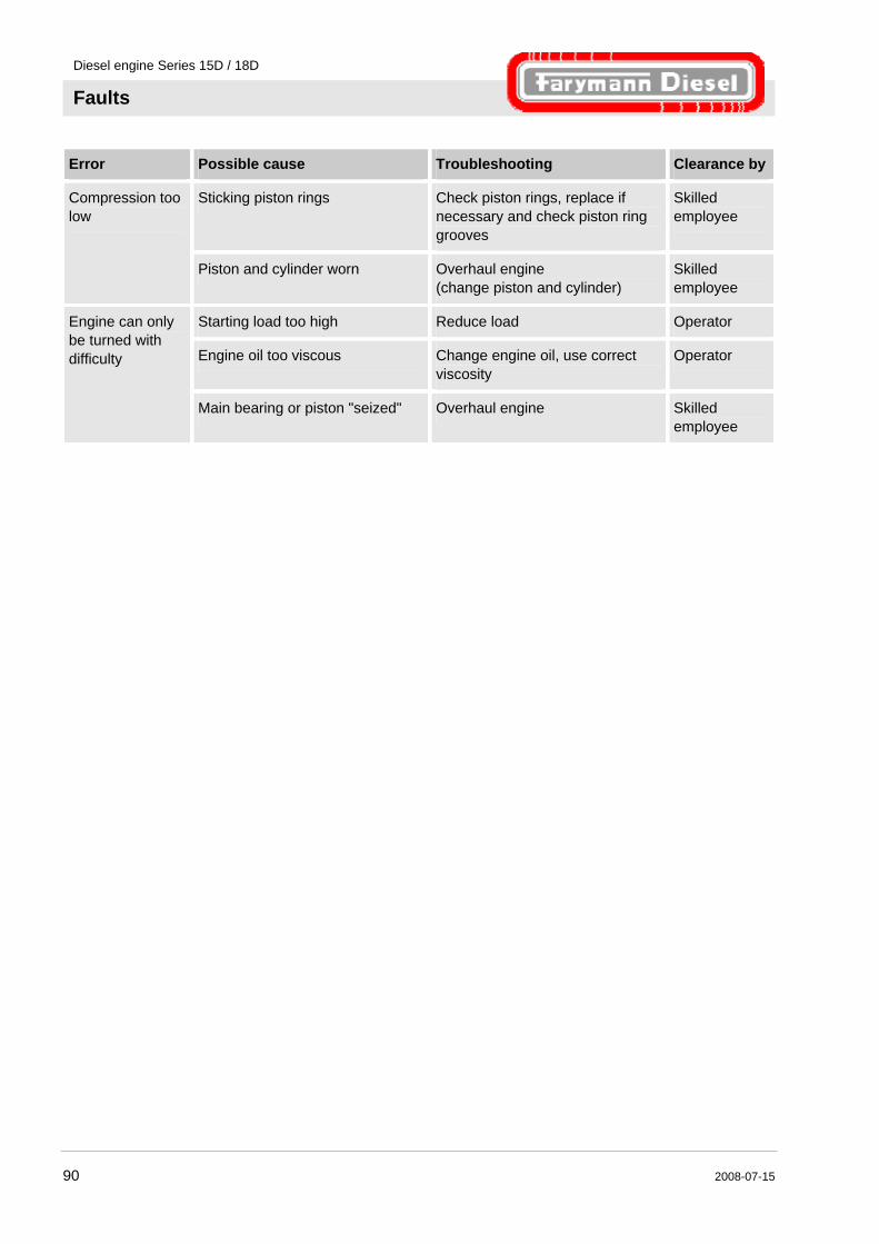
Diesel engine Series 15D / 18D
Faults
90 2008-07-15
Error Possible cause Troubleshooting Clearance by
Sticking piston rings Check piston rings, replace if necessary and check piston ring grooves
Skilled employee
Compression too low
Piston and cylinder worn Overhaul engine (change piston and cylinder)
Skilled employee
Starting load too high Reduce load Operator
Engine oil too viscous Change engine oil, use correct viscosity
Operator
Engine can only be turned with difficulty
Main bearing or piston "seized" Overhaul engine Skilled employee
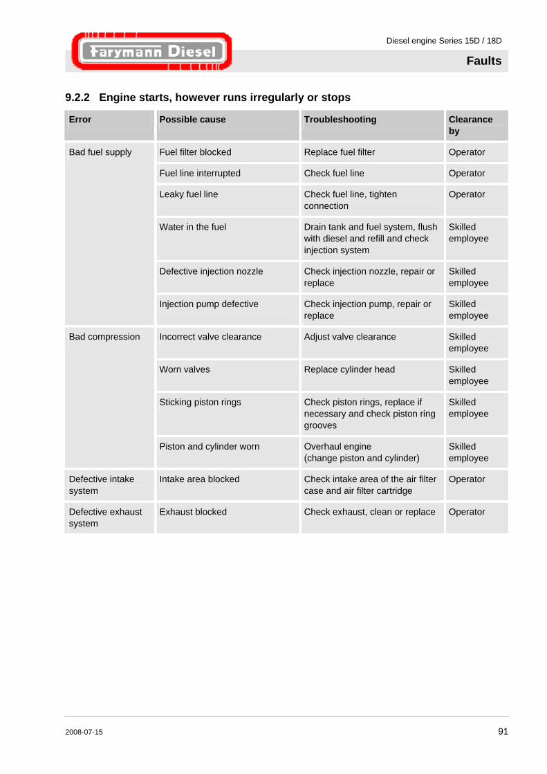
Diesel engine Series 15D / 18D
Faults
2008-07-15 91
9.2.2 Engine starts, however runs irregularly or stops
Error Possible cause Troubleshooting Clearance by
Fuel filter blocked Replace fuel filter Operator
Fuel line interrupted Check fuel line Operator
Leaky fuel line Check fuel line, tighten connection
Operator
Water in the fuel Drain tank and fuel system, flush with diesel and refill and check injection system
Skilled employee
Defective injection nozzle Check injection nozzle, repair or replace
Skilled employee
Bad fuel supply
Injection pump defective Check injection pump, repair or replace
Skilled employee
Incorrect valve clearance Adjust valve clearance Skilled employee
Worn valves Replace cylinder head Skilled employee
Sticking piston rings Check piston rings, replace if necessary and check piston ring grooves
Skilled employee
Bad compression
Piston and cylinder worn Overhaul engine (change piston and cylinder)
Skilled employee
Defective intake system
Intake area blocked Check intake area of the air filter case and air filter cartridge
Operator
Defective exhaust system
Exhaust blocked Check exhaust, clean or replace Operator
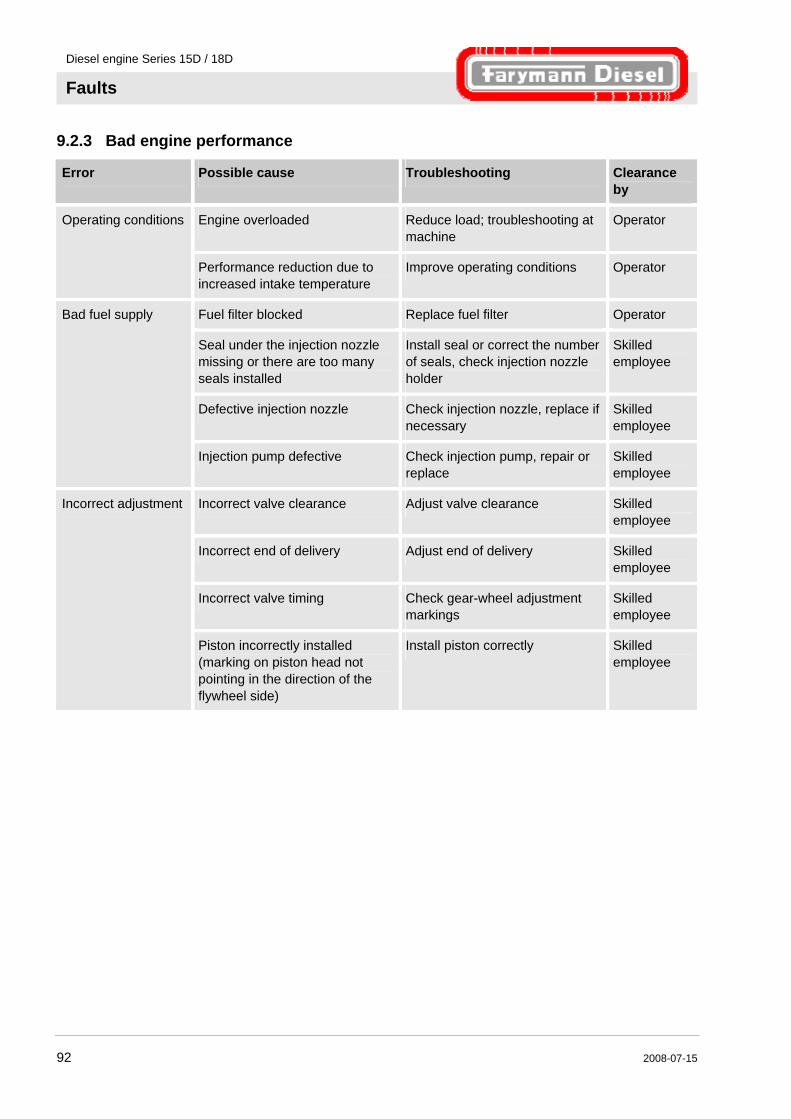
Diesel engine Series 15D / 18D
Faults
92 2008-07-15
9.2.3 Bad engine performance
Error Possible cause Troubleshooting Clearance by
Engine overloaded Reduce load; troubleshooting at machine
Operator Operating conditions
Performance reduction due to increased intake temperature
Improve operating conditions Operator
Fuel filter blocked Replace fuel filter Operator
Seal under the injection nozzle missing or there are too many seals installed
Install seal or correct the number of seals, check injection nozzle holder
Skilled employee
Defective injection nozzle Check injection nozzle, replace if necessary
Skilled employee
Bad fuel supply
Injection pump defective Check injection pump, repair or replace
Skilled employee
Incorrect valve clearance Adjust valve clearance Skilled employee
Incorrect end of delivery Adjust end of delivery Skilled employee
Incorrect valve timing Check gear-wheel adjustment markings
Skilled employee
Incorrect adjustment
Piston incorrectly installed (marking on piston head not pointing in the direction of the flywheel side)
Install piston correctly Skilled employee

Diesel engine Series 15D / 18D
Faults
2008-07-15 93
9.2.4 Operating behaviour not faultless
Error Possible cause Troubleshooting Clearance by
Engine overloaded Reduce load Operator
Cooling fins dirty Clean cooling fins Operator
Cooling air inlet blocked Check air inlet, clean if necessary
Operator
Cooling air supply blocked Improve cooling air supply, check engine installation
Operator
Oil level in the crankcase too high
Correct oil level Operator
Overheating
Defective injection nozzle Check injection nozzle, repair or replace
Skilled employee
Carbon deposit on piston head Remove carbon deposits on piston, replace piston and cylinder if necessary
Skilled employee
Injection nozzle needle sticks / jams
Replace injection nozzle Skilled employee
Incorrect end of delivery Incorrect begin of delivery
Check and adjust begin of delivery / end of delivery
Skilled employee
Broken piston rings Replace piston rings, check piston and cylinder
Skilled employee
Piston and cylinder worn Overhaul engine (change piston and cylinder)
Skilled employee
Main bearing, connecting road bearing worn
Overhaul engine Skilled employee
Loose flywheel Check flywheel and crankshaft for damage, overhaul engine if necessary
Skilled employee
Knocking noises
Petrol mixture in the tank Drain tank and fuel system, flush with diesel, fill with new fuel and check engine, arrange overhaul if necessary
Skilled employee
Overheating See: Overheating Strong speed fluctuations
Air in the fuel system Check fuel system for leaks Operator
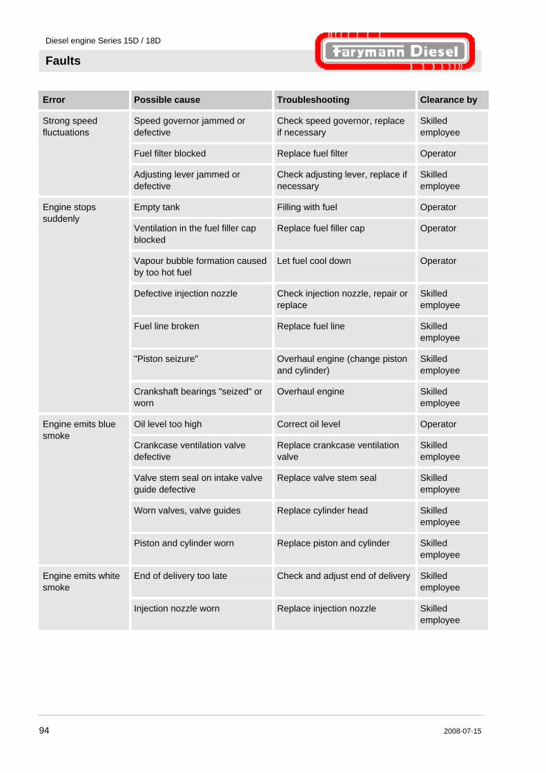
Diesel engine Series 15D / 18D
Faults
94 2008-07-15
Error Possible cause Troubleshooting Clearance by
Speed governor jammed or defective
Check speed governor, replace if necessary
Skilled employee
Fuel filter blocked Replace fuel filter Operator
Strong speed fluctuations
Adjusting lever jammed or defective
Check adjusting lever, replace if necessary
Skilled employee
Empty tank Filling with fuel Operator
Ventilation in the fuel filler cap blocked
Replace fuel filler cap Operator
Vapour bubble formation caused by too hot fuel
Let fuel cool down Operator
Defective injection nozzle Check injection nozzle, repair or replace
Skilled employee
Fuel line broken Replace fuel line Skilled employee
"Piston seizure" Overhaul engine (change piston and cylinder)
Skilled employee
Engine stops suddenly
Crankshaft bearings "seized" or worn
Overhaul engine Skilled employee
Oil level too high Correct oil level Operator
Crankcase ventilation valve defective
Replace crankcase ventilation valve
Skilled employee
Valve stem seal on intake valve guide defective
Replace valve stem seal Skilled employee
Worn valves, valve guides Replace cylinder head Skilled employee
Engine emits blue smoke
Piston and cylinder worn Replace piston and cylinder Skilled employee
End of delivery too late Check and adjust end of delivery Skilled employee
Engine emits white smoke
Injection nozzle worn Replace injection nozzle Skilled employee
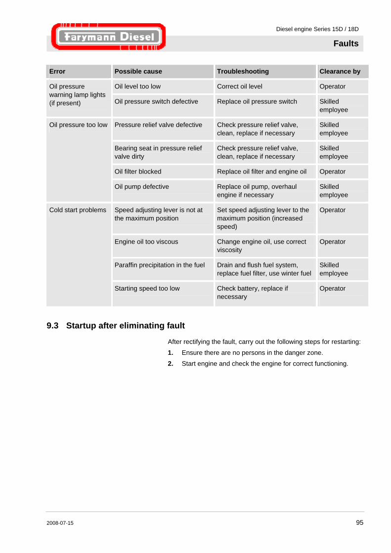
Diesel engine Series 15D / 18D
Faults
2008-07-15 95
Error Possible cause Troubleshooting Clearance by
Oil level too low Correct oil level Operatoroil
Oil pressure warning lamp lights (if present) Oil pressure switch defective Replace oil pressure switch Skilled
employee
Pressure relief valve defective Check pressure relief valve, clean, replace if necessary
Skilled employee
Bearing seat in pressure relief valve dirty
Check pressure relief valve, clean, replace if necessary
Skilled employee
Oil filter blocked Replace oil filter and engine oil Operator
Oil pressure too low
Oil pump defective Replace oil pump, overhaul engine if necessary
Skilled employee
Speed adjusting lever is not at the maximum position
Set speed adjusting lever to the maximum position (increased speed)
Operator
Engine oil too viscous Change engine oil, use correct viscosity
Operator
Paraffin precipitation in the fuel Drain and flush fuel system, replace fuel filter, use winter fuel
Skilled employee
Cold start problems
Starting speed too low Check battery, replace if necessary
Operator
9.3 Startup after eliminating fault
After rectifying the fault, carry out the following steps for restarting:
1. Ensure there are no persons in the danger zone. 2. Start engine and check the engine for correct functioning.
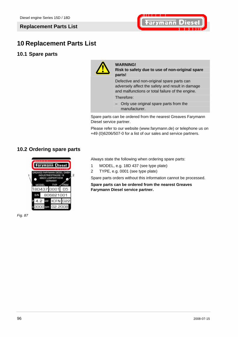
Diesel engine Series 15D / 18D
Replacement Parts List
96 2008-07-15
10 Replacement Parts List
10.1 Spare parts
WARNING! Risk to safety due to use of non-original spare parts! Defective and non-original spare parts can adversely affect the safety and result in damage and malfunctions or total failure of the engine. Therefore: – Only use original spare parts from the
manufacturer.
Spare parts can be ordered from the nearest Greaves Farymann Diesel service partner.
Please refer to our website (www.farymann.de) or telephone us on +49 (0)6206/507-0 for a list of our sales and service partners.
10.2 Ordering spare parts
Fig. 87
Always state the following when ordering spare parts:
1 MODEL, e.g. 18D 437 (see type plate) 2 TYPE, e.g. 0001 (see type plate)
Spare parts orders without this information cannot be processed.
Spare parts can be ordered from the nearest Greaves Farymann Diesel service partner.
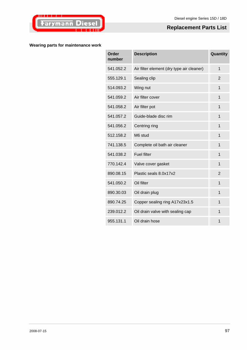
Diesel engine Series 15D / 18D
Replacement Parts List
2008-07-15 97
Wearing parts for maintenance work
Order number
Description Quantity
541.052.2 Air filter element (dry type air cleaner) 1
555.129.1 Sealing clip 2
514.093.2 Wing nut 1
541.059.2 Air filter cover 1
541.058.2 Air filter pot 1
541.057.2 Guide-blade disc rim 1
541.056.2 Centring ring 1
512.158.2 M6 stud 1
741.138.5 Complete oil bath air cleaner 1
541.038.2 Fuel filter 1
770.142.4 Valve cover gasket 1
890.08.15 Plastic seals 8.0x17x2 2
541.050.2 Oil filter 1
890.30.03 Oil drain plug 1
890.74.25 Copper sealing ring A17x23x1.5 1
239.012.2 Oil drain valve with sealing cap 1
955.131.1 Oil drain hose 1
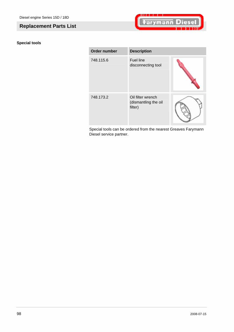
Diesel engine Series 15D / 18D
Replacement Parts List
98 2008-07-15
Special tools
Order number Description
748.115.6 Fuel line disconnecting tool
748.173.2 Oil filter wrench (dismantling the oil filter)
Special tools can be ordered from the nearest Greaves Farymann Diesel service partner.

Diesel engine Series 15D / 18D
Service history
2008-07-15 99
11 Service history
11.1 Proof of purchase
Fig. 88
Using the type plate, copy the following information on to the proof of purchase and arrange confirmation. There is a type plate on the engine with the following information:
1 Model 2 Type number 3 Version of the speed governor 4 Serial number 5 Date of manufacture
Description Please fill in:
1 Model
2 Type number
3 TRIM
4 Serial number (S/N)
5 Date of manufacture
Date of purchase
by Dealer stamp
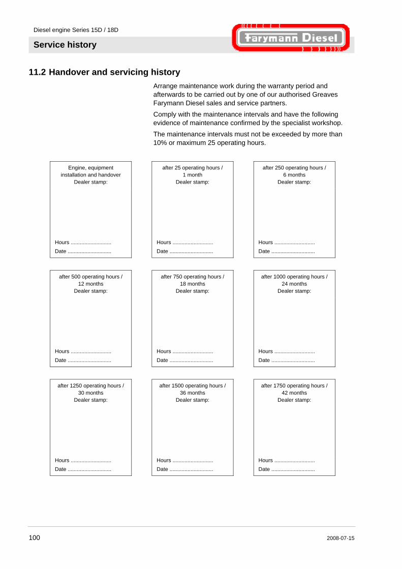
Diesel engine Series 15D / 18D
Service history
100 2008-07-15
11.2 Handover and servicing history Arrange maintenance work during the warranty period and afterwards to be carried out by one of our authorised Greaves Farymann Diesel sales and service partners.
Comply with the maintenance intervals and have the following evidence of maintenance confirmed by the specialist workshop.
The maintenance intervals must not be exceeded by more than 10% or maximum 25 operating hours.
Engine, equipment installation and handover
Dealer stamp:
after 25 operating hours / 1 month
Dealer stamp:
after 250 operating hours / 6 months
Dealer stamp:
Hours ...........................
Date ............................. Hours ...........................
Date ............................. Hours ...........................
Date .............................
after 500 operating hours / 12 months
Dealer stamp:
after 750 operating hours / 18 months
Dealer stamp:
after 1000 operating hours / 24 months
Dealer stamp:
Hours ...........................
Date ............................. Hours ...........................
Date ............................. Hours ...........................
Date .............................
after 1250 operating hours / 30 months
Dealer stamp:
after 1500 operating hours / 36 months
Dealer stamp:
after 1750 operating hours / 42 months
Dealer stamp:
Hours ...........................
Date ............................. Hours ...........................
Date ............................. Hours ...........................
Date .............................
Diesel engine Series 15D / 18D
Service history
2008-07-15 101
after 2000 operating hours / 48 months
Dealer stamp:
after 2250 operating hours / 54 months
Dealer stamp:
after 2500 operating hours / 60 months
Dealer stamp:
Hours ...........................
Date ............................. Hours ...........................
Date ............................. Hours ...........................
Date .............................
after 2750 operating hours / 66 months
Dealer stamp:
after 3000 operating hours / 72 months
Dealer stamp:
after 3250 operating hours / 78 months
Dealer stamp:
Hours ...........................
Date ............................. Hours ...........................
Date ............................. Hours ...........................
Date .............................
after 3500 operating hours / 84 months
Dealer stamp:
after 3750 operating hours / 90 months
Dealer stamp:
after 4000 operating hours / 96 months
Dealer stamp:
Hours ...........................
Date ............................. Hours ...........................
Date ............................. Hours ...........................
Date .............................
Diesel engine Series 15D / 18D
Service history
102 2008-07-15
after 4250 operating hours /
102 months Dealer stamp:
after 4500 operating hours / 108 months
Dealer stamp:
after 4750 operating hours / 114 months
Dealer stamp:
Hours ...........................
Date ............................. Hours ...........................
Date ............................. Hours ...........................
Date .............................
after 5000 operating hours / 120 months
Dealer stamp:
after 5250 operating hours / 126 months
Dealer stamp:
after 5500 operating hours / 132 months
Dealer stamp:
Hours ...........................
Date ............................. Hours ...........................
Date ............................. Hours ...........................
Date .............................
after 5750 operating hours / 138 months
Dealer stamp:
after 6000 operating hours / 144 months
Dealer stamp:
after 6250 operating hours / 150 months
Dealer stamp:
Hours ...........................
Date ............................. Hours ...........................
Date ............................. Hours ...........................
Date .............................

Diesel engine Series 15D / 18D
Service history
2008-07-15 103
after 6500 operating hours /
156 months Dealer stamp:
after 6750 operating hours / 162 months
Dealer stamp:
after 7000 operating hours / 168 months
Dealer stamp:
Hours ...........................
Date ............................. Hours ...........................
Date ............................. Hours ...........................
Date .............................
after 7250 operating hours / 174 months
Dealer stamp:
after 7500 operating hours / 180 months
Dealer stamp:
after 7750 operating hours / 186 months
Dealer stamp:
Hours ...........................
Date ............................. Hours ...........................
Date ............................. Hours ...........................
Date .............................
after 8000 operating hours / 192 months
Dealer stamp:
after 8250 operating hours / 198 months
Dealer stamp:
after 8500 operating hours / 204 months
Dealer stamp:
Hours ...........................
Date ............................. Hours ...........................
Date ............................. Hours ...........................
Date .............................
NOTE! Further service histories can be ordered from the nearest Greaves Farymann Diesel sales or service partner. Refer to our website for a list of our sales partners.
Diesel engine Series 15D / 18D
Index
104 2008-07-15
12 Index
A
Accident ............................................................. 18 Adjusting valve clearance .................................. 77
Applications........................................................ 20 Appropriate use.................................................. 13
Attachment points .............................................. 35
B
Batteries............................................................. 32
C
Checking threaded connections ........................ 66 Cleaning cooling air area ................................... 66
Cleaning the intake area.................................... 65 Cold start............................................................ 50 Cold starting aids ............................. 40, 50, 54, 56
Commissioning .................................................. 40 Copyright.............................................................. 9
Customer service................................................. 9
D
Danger zone ...................................................... 18 Dangers and cause of failure............................. 31
Decommissioning............................................... 59 Dimensions ........................................................ 24
E
Ear defenders .................................................... 14
Electrical System ............................................... 30 EMERGENCY STOP......................................... 48
Engine data........................................................ 23 Engine oil
changing......................................................... 68 filling ............................................................... 41
Specification................................................... 27 Engine type code ............................................... 22
Engine type plate ............................................... 21 Environmental protection ................................... 19
Exhaust gases ................................................... 47
F
Faults ................................................................. 86
Fire ..................................................................... 18 First aid .............................................................. 18 Fuel
filling ............................................................... 43 Fuel filter
replacing ......................................................... 71 Fuels .................................................................. 19
H
Hard hat ............................................................. 14
I Installation .......................................................... 36
Instruction........................................................... 12
L
Liability ................................................................. 8 Lubricants........................................................... 19
M
Maintenance....................................................... 60
Maintenance plan............................................... 62 Manual starting................................................... 50
Misuse................................................................ 13
O
Oil bath air cleaner............................................. 75 Operating conditions .......................................... 30
Operating materials...................................... 17, 26 Operation ..................................................... 46, 55 Options............................................................... 21 Overview ............................................................ 28
Owner................................................................. 10
P
Packing ........................................................ 33, 34 Parts
rotating............................................................ 46
Personal protective equipment .......................... 14

Diesel engine Series 15D / 18D
Index
2008-07-15 105
Personnel............................................................12
commissioning ................................................36 Faults ..............................................................86
installation .......................................................36 Maintenance ...................................................61
Pressures............................................................25 Protective equipment..........................................14
Faults ..............................................................86 Installation.......................................................61
Operation ........................................................48 Protective gloves ................................................14
R
Replacement parts .............................................96 Replacement parts list ........................................96
Replacing air filter...............................................73 Replacing oil filter ...............................................70
Risk of fire...........................................................17
S
Safety general ............................................................10
Safety boots........................................................14 Safety devices ....................................................18
Safety goggles....................................................14 Service..................................................................9
Service history ....................................................99
Spare parts .........................................................96
Ordering ..........................................................96 Standard configuration........................................21
Starting with electric starter ................................54 Storage .........................................................33, 35
Surfaces, hot.................................................17, 47 Switching off .......................................................57
Symbols in the operator's manual....................................7
T
Technical data ....................................................20 Technical personnel............................................12
Temperatures .....................................................25 Transport.......................................................33, 35
Crane...............................................................35 Inspection........................................................33
Troubleshooting Chart................................................................89
U
Usage..................................................................13
W
Warm start ..........................................................50
Warranty ...............................................................9 Weight.................................................................24

Diesel engine Series 15D / 18D
Notes
106 2008-07-15
Notes

Diesel engine Series 15D / 18D
Notes
2008-07-15 107
Notes

Diesel engine Series 15D / 18D
Notes
108 2008-07-15
Notes

Art. 903.01.42 06/08