DieMax L Die Springs - daytonlamina.com · Die Spring Basics A die spring is a highly engineered...
16
DieMax ™ L Die Springs www.daytonlamina.com Check our website for the latest technical information. MADE IN AMERICA
Transcript of DieMax L Die Springs - daytonlamina.com · Die Spring Basics A die spring is a highly engineered...
DieMax™ L Die Springs
www.daytonlamina.comCheck our website for the latest technical information.
MADE IN AMERICA
Die Spring BasicsA die spring is a highly engineered mechanical spring with specific wire designs that stores energy elastically by resisting movement when pressure is applied. The desired wire segment is selected to produce the maximum amount of force within a minimal amount of space.
Altering Die Springs Each die spring is carefully engineered to perform within specific applications. Under no circumstances should you alter a die spring. Altering a die spring will change its designed characteristics and allows additional stresses to occur causing early failure. Grinding on the die spring not only changes the spring’s original properties, but the heat from grinding can change the temper of the material and negatively affect the spring’s performance.
Compressed Length The sum of the preload travel and operating travel.
Corrosion Frequently, die spring failure can be traced to corrosive elements which affect the surface of the spring’s material, causing premature failure. Be aware of conditions that may affect the spring’s surface such as rust, lubricants, soaps, and chemicals. Clean, protected die springs provide the best performance.
Cycle Rate The more rapidly a spring is cycled, the greater the need to operate in the recommended long life deflections from the catalog.
Die Spring Guidance Make sure that the hole size and/or rod size match the die spring’s operating dimensions.
Duty Ranges We offer 4 separate duty ranges to best suit your applications – Medium Duty, Medium Heavy Duty, Heavy Duty, and Extra Heavy Duty. Do not mix springs of different duties.
Free Length The length of the spring without any load or force applied.
Hole Diameter Die springs are designed to be used in a hole dimension as indicated in the catalog. The actual O.D. will be somewhat smaller to prevent interference.
Material In our case, the spring material is High Tensile Strength Chrome Silicon Material. We use an optimal rectangular wire design. The maximum rated service temperature is 425°F.
Operating Travel Operating travel is the deflection of the spring where it is operating between the preload and the total travel of the spring during operation. This is the area where the actual work is performed.
Preload The initial force which is applied to a die spring. Preload is recommended to compress the first coils at each end where additional stresses are present because of the turn-down of the end coils. Applying a preload will extend the life of the spring.
Quality Our die springs are manufactured in an ISO 9001:2015 facility.
Rates Die spring rates are normally listed as Pounds per Inch of deflection (i.e. 60 pounds load per inch.) As a die spring is deflected, the loads will increase for the amount of travel it is deflected. That is, a spring with a 60lb/inch rate will produce 60 lbs of resistance at 1” of travel, 120 lbs. at 2” of travel, etc. For purposes of simplification, the loads in our catalog are shown in pounds needed to deflect a spring 1/10th of an inch. Simply multiply the rates given by 10 to determine the actual spring rate.
Rod Diameter Die springs are designed to fit over a rod for guidance and the actual I.D. of the spring is actually some- what larger to fit over a rod without interference.
Solid Height Solid height is the height of the spring when all of the coils are totally collapsed to solid. You never want to operate a die spring close to this condition.
DIEMAXTM L DIE SPRINGS
MADE IN AMERICA
www.daytonlamina.comCheck our website for the latest technical information.
1
Inch Die Springs
Medium Duty – Blue 2
Medium Heavy Duty – Red 4
Heavy Duty – Gold 6
Extra Heavy Duty – Green 8
Spring Accessories 10
Special Heavy Duty Compression Springs 12
TABLE OF CONTENTS pAgE NumBEr
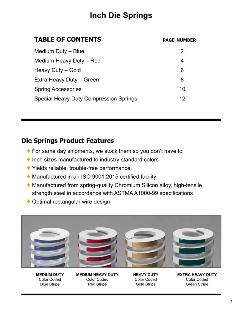
MEDIUM DUTYColor Coded Blue Stripe
MEDIUM HEAVY DUTYColor CodedRed Stripe
HEAVY DUTYColor Coded Gold Stripe
EXTRA HEAVY DUTYColor CodedGreen Stripe
Die Springs Product Features ♦ For same day shipments, we stock them so you don’t have to ♦ Inch sizes manufactured to industry standard colors ♦ Yields reliable, trouble-free performance ♦ Manufactured in an ISO 9001:2015 certified facility ♦ Manufactured from spring-quality Chromium Silicon alloy, high-tensile strength steel in accordance with ASTMA A1000-99 specifications ♦ Optimal rectangular wire design
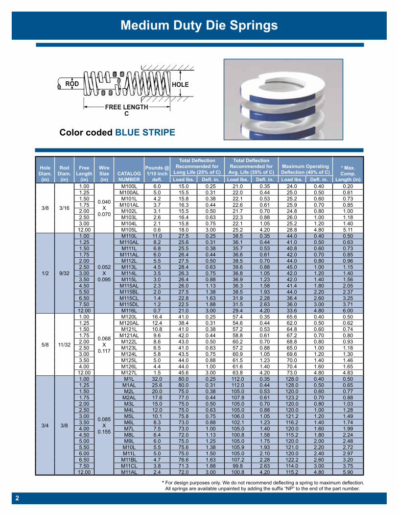
Medium Duty Die Springs
Color coded BLUE STRIPE
Hole Diam.
(in)
Rod Diam.
(in)
Free Length
(in)
Wire Size (in)
CATALOG NUMBER
Pounds @ 1/10 inch
defl.
Total Deflection Recommended for
Long Life (25% of C)
Total Deflection Recommended for
Avg. Life (35% of C)Maximum Operating Deflection (40% of C)
* Max. Comp.
Length (in)Load lbs. Defl. in. Load lbs. Defl. in. Load lbs. Defl. in.
3/8 3/16
1.00
0.040 X
0.070
M100L 6.0 15.0 0.25 21.0 0.35 24.0 0.40 0.201.25 M100AL 5.0 15.5 0.31 22.0 0.44 25.0 0.50 0.611.50 M101L 4.2 15.8 0.38 22.1 0.53 25.2 0.60 0.731.75 M101AL 3.7 16.3 0.44 22.6 0.61 25.9 0.70 0.852.00 M102L 3.1 15.5 0.50 21.7 0.70 24.8 0.80 1.002.50 M103L 2.6 16.4 0.63 22.3 0.88 26.0 1.00 1.183.00 M104L 2.1 15.8 0.75 22.1 1.05 25.2 1.20 1.4012.00 M105L 0.6 18.0 3.00 25.2 4.20 28.8 4.80 5.11
1/2 9/32
1.00
0.052 X
0.095
M110L 11.0 27.5 0.25 38.5 0.35 44.0 0.40 0.501.25 M110AL 8.2 25.6 0.31 36.1 0.44 41.0 0.50 0.631.50 M111L 6.8 25.5 0.38 35.7 0.53 40.8 0.60 0.731.75 M111AL 6.0 26.4 0.44 36.6 0.61 42.0 0.70 0.852.00 M112L 5.5 27.5 0.50 38.5 0.70 44.0 0.80 0.962.50 M113L 4.5 28.4 0.63 39.6 0.88 45.0 1.00 1.153.00 M114L 3.5 26.3 0.75 36.8 1.05 42.0 1.20 1.403.50 M115L 3.0 26.4 0.88 36.9 1.23 42.0 1.40 1.564.50 M115AL 2.3 26.0 1.13 36.3 1.58 41.4 1.80 2.055.50 M115BL 2.0 27.5 1.38 38.5 1.93 44.0 2.20 2.376.50 M115CL 1.4 22.8 1.63 31.9 2.28 36.4 2.60 3.257.50 M115DL 1.2 22.5 1.88 31.5 2.63 36.0 3.00 3.7112.00 M116L 0.7 21.0 3.00 29.4 4.20 33.6 4.80 6.00
5/8 11/32
1.00
0.068 X
0.117
M120L 16.4 41.0 0.25 57.4 0.35 65.6 0.40 0.501.25 M120AL 12.4 38.4 0.31 54.6 0.44 62.0 0.50 0.621.50 M121L 10.8 41.0 0.38 57.2 0.53 64.8 0.60 0.741.75 M121AL 9.6 42.0 0.44 58.8 0.61 67.2 0.70 0.802.00 M122L 8.6 43.0 0.50 60.2 0.70 68.8 0.80 0.932.50 M123L 6.5 41.0 0.63 57.2 0.88 65.0 1.00 1.183.00 M124L 5.8 43.5 0.75 60.9 1.05 69.6 1.20 1.303.50 M125L 5.0 44.0 0.88 61.5 1.23 70.0 1.40 1.464.00 M126L 4.4 44.0 1.00 61.6 1.40 70.4 1.60 1.6512.00 M127L 1.5 45.6 3.00 63.8 4.20 73.0 4.80 4.83
3/4 3/8
1.00
0.085 X
0.155
M1L 32.0 80.0 0.25 112.0 0.35 128.0 0.40 0.501.25 M1AL 25.6 80.0 0.31 112.0 0.44 128.0 0.50 0.651.50 M2L 20.0 75.0 0.38 105.0 0.53 120.0 0.60 0.771.75 M2AL 17.6 77.0 0.44 107.8 0.61 123.2 0.70 0.882.00 M3L 15.0 75.0 0.50 105.0 0.70 120.0 0.80 1.032.50 M4L 12.0 75.0 0.63 105.0 0.88 120.0 1.00 1.283.00 M5L 10.1 75.8 0.75 106.0 1.05 121.2 1.20 1.493.50 M6L 8.3 73.0 0.88 102.1 1.23 116.2 1.40 1.744.00 M7L 7.5 73.0 1.00 105.0 1.40 120.0 1.60 1.994.50 M8L 6.4 72.0 1.13 100.8 1.58 115.2 1.80 2.245.00 M9L 6.0 75.0 1.25 105.0 1.75 120.0 2.00 2.485.50 M10L 5.5 75.6 1.38 105.9 1.93 121.0 2.20 2.726.00 M11L 5.0 75.0 1.50 105.0 2.10 120.0 2.40 2.976.50 M11BL 4.7 76.6 1.63 107.2 2.28 122.2 2.60 3.207.50 M11CL 3.8 71.3 1.88 99.8 2.63 114.0 3.00 3.7512.00 M11AL 2.4 72.0 3.00 100.8 4.20 115.2 4.80 5.90
* For design purposes only. We do not recommend deflecting a spring to maximum deflection. All springs are available unpainted by adding the suffix “NP” to the end of the part number.
2
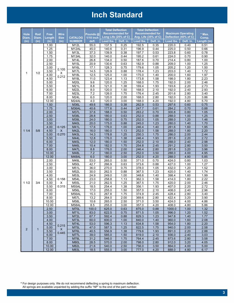
Inch Standard
Hole Diam.
(in)
Rod Diam.
(in)
Free Length
(in)
Wire Size (in)
CATALOG NUMBER
Pounds @ 1/10 inch
defl.
Total Deflection Recommended for
Long Life (25% of C)
Total Deflection Recommended for
Avg. Life (35% of C)Maximum Operating Deflection (40% of C)
* Max. Comp.
Length (in)Load lbs. Defl. in. Load lbs. Defl. in. Load lbs. Defl. in.
1 1/2
1.00
0.105 X
0.212
M12L 55.0 137.5 0.25 192.5 0.35 220.0 0.40 0.511.25 M12AL 45.0 140.6 0.31 196.9 0.44 225.0 0.50 0.661.50 M13L 37.3 139.9 0.38 197.7 0.53 223.8 0.60 0.781.75 M13AL 32.0 140.0 0.44 195.2 0.61 224.0 0.70 0.902.00 M14L 26.8 134.0 0.50 187.6 0.70 214.4 0.80 1.002.50 M15L 20.9 130.6 0.63 182.9 0.88 209.0 1.00 1.253.00 M16L 17.1 128.3 0.75 179.6 1.05 205.2 1.20 1.503.50 M17L 14.5 126.9 0.88 178.4 1.23 203.0 1.40 1.724.00 M18L 12.5 125.0 1.00 175.0 1.40 200.0 1.60 1.974.50 M19L 11.0 123.4 1.13 173.8 1.58 198.0 1.80 2.235.00 M20L 9.6 120.0 1.25 168.0 1.75 192.0 2.00 2.465.50 M21L 8.8 121.0 1.38 169.4 1.93 193.6 2.20 2.736.00 M22L 8.0 120.0 1.50 168.0 2.10 192.0 2.40 2.937.00 M23L 7.2 126.0 1.75 176.4 2.45 201.6 2.80 3.408.00 M24L 6.0 120.0 2.00 168.0 2.80 192.0 3.20 3.8612.00 M24AL 4.0 120.0 3.00 168.0 4.20 192.0 4.80 5.70
1 1/4 5/8
1.50
0.125 X
0.270
M36L 49.6 186.0 0.38 262.9 0.53 297.6 0.60 0.751.75 M36AL 40.6 177.6 0.44 247.7 0.61 284.2 0.70 0.882.00 M37L 37.6 188.0 0.50 263.2 0.70 300.8 0.80 1.052.50 M38L 28.8 180.0 0.63 252.0 0.88 288.0 1.00 1.253.00 M39L 24.0 180.0 0.75 252.0 1.05 288.0 1.20 1.463.50 M40L 20.0 175.0 0.88 245.0 1.23 280.0 1.40 1.704.00 M41L 17.6 176.0 1.00 246.4 1.40 281.6 1.60 1.954.50 M42L 16.0 180.0 1.13 252.0 1.58 288.0 1.80 2.205.00 M43L 14.3 178.8 1.25 250.3 1.75 286.0 2.00 2.445.50 M44L 12.8 176.0 1.38 246.4 1.93 281.6 2.20 2.726.00 M45L 12.0 180.0 1.50 252.0 2.10 288.0 2.40 2.987.00 M46L 10.4 182.0 1.75 254.8 2.45 291.2 2.80 3.508.00 M47L 8.8 176.0 2.00 246.4 2.80 281.6 3.20 3.9610.00 M48L 7.2 180.0 2.50 252.0 3.50 288.0 4.00 4.9512.00 M48AL 6.0 180.0 3.00 252.0 4.20 288.0 4.80 5.85
1 1/2 3/4
2.00
0.158 X
0.315
M49L 53.0 265.0 0.50 371.0 0.70 424.0 0.80 1.032.50 M50L 42.7 266.9 0.63 373.6 0.88 427.0 1.00 1.273.00 M51L 36.0 270.0 0.75 378.0 1.05 432.0 1.20 1.523.50 M52L 30.0 262.5 0.88 367.5 1.23 420.0 1.40 1.744.00 M53L 24.9 249.0 1.00 348.6 1.40 398.4 1.60 1.994.50 M54L 23.0 258.8 1.13 362.3 1.58 414.0 1.80 2.225.00 M55L 21.0 262.5 1.25 367.5 1.75 420.0 2.00 2.465.50 M55AL 18.5 254.4 1.38 356.1 1.93 407.0 2.20 2.726.00 M56L 17.0 255.0 1.50 357.0 2.10 408.0 2.40 2.967.00 M56AL 15.3 267.8 1.75 374.9 2.45 428.4 2.80 3.408.00 M57L 13.2 264.0 2.00 369.6 2.80 422.4 3.20 3.9010.00 M58L 10.6 265.0 2.50 371.0 3.50 424.0 4.00 4.8612.00 M58AL 8.5 255.0 3.00 357.0 4.20 408.0 4.80 5.86
2 1
2.50
0.215 X
0.445
M70L 100.0 625.0 0.63 875.0 0.88 1000.0 1.00 1.323.00 M71L 83.0 622.5 0.75 871.5 1.05 996.0 1.20 1.523.50 M72L 67.7 592.4 0.88 829.3 1.23 947.8 1.40 1.774.00 M73L 60.0 600.0 1.00 840.0 1.40 960.0 1.60 2.084.50 M74L 53.0 596.3 1.13 834.8 1.58 954.0 1.80 2.205.00 M75L 47.0 587.5 1.25 822.5 1.75 940.0 2.00 2.585.50 M76L 40.5 556.9 1.38 779.6 1.93 891.0 2.20 2.886.00 M77L 39.0 585.0 1.50 819.0 2.10 936.0 2.40 3.037.00 M79L 31.2 546.0 1.75 764.4 2.45 873.6 2.80 3.588.00 M80L 28.5 570.0 2.00 798.0 2.80 912.0 3.20 4.0510.00 M82L 21.6 540.0 2.50 756.0 3.50 864.0 4.00 5.0012.00 M83L 18.5 555.0 3.00 777.0 4.20 888.0 4.80 6.17
* For design purposes only. We do not recommend deflecting a spring to maximum deflection. All springs are available unpainted by adding the suffix “NP” to the end of the part number.
3
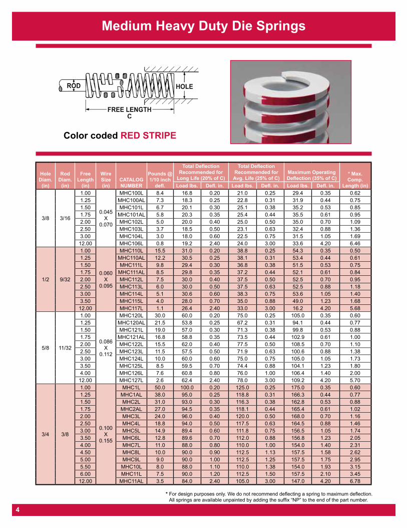
Medium Heavy Duty Die Springs
Color coded RED STRIPE
Hole Diam.
(in)
Rod Diam.
(in)
Free Length
(in)
Wire Size (in)
CATALOG NUMBER
Pounds @ 1/10 inch
defl.
Total Deflection Recommended for
Long Life (20% of C)
Total Deflection Recommended for
Avg. Life (25% of C)Maximum Operating Deflection (35% of C)
* Max. Comp.
Length (in)Load lbs. Defl. in. Load lbs. Defl. in. Load lbs. Defl. in.
3/8 3/16
1.00
0.045 X
0.070
MHC100L 8.4 16.8 0.20 21.0 0.25 29.4 0.35 0.621.25 MHC100AL 7.3 18.3 0.25 22.8 0.31 31.9 0.44 0.751.50 MHC101L 6.7 20.1 0.30 25.1 0.38 35.2 0.53 0.851.75 MHC101AL 5.8 20.3 0.35 25.4 0.44 35.5 0.61 0.952.00 MHC102L 5.0 20.0 0.40 25.0 0.50 35.0 0.70 1.092.50 MHC103L 3.7 18.5 0.50 23.1 0.63 32.4 0.88 1.363.00 MHC104L 3.0 18.0 0.60 22.5 0.75 31.5 1.05 1.69
12.00 MHC106L 0.8 19.2 2.40 24.0 3.00 33.6 4.20 6.46
1/2 9/32
1.00
0.060 X
0.095
MHC110L 15.5 31.0 0.20 38.8 0.25 54.3 0.35 0.501.25 MHC110AL 12.2 30.5 0.25 38.1 0.31 53.4 0.44 0.611.50 MHC111L 9.8 29.4 0.30 36.8 0.38 51.5 0.53 0.751.75 MHC111AL 8.5 29.8 0.35 37.2 0.44 52.1 0.61 0.842.00 MHC112L 7.5 30.0 0.40 37.5 0.50 52.5 0.70 0.952.50 MHC113L 6.0 30.0 0.50 37.5 0.63 52.5 0.88 1.183.00 MHC114L 5.1 30.6 0.60 38.3 0.75 53.6 1.05 1.403.50 MHC115L 4.0 28.0 0.70 35.0 0.88 49.0 1.23 1.6812.00 MHC117L 1.1 26.4 2.40 33.0 3.00 16.2 4.20 5.68
5/8 11/32
1.00
0.086 X
0.112
MHC120L 30.0 60.0 0.20 75.0 0.25 105.0 0.35 0.601.25 MHC120AL 21.5 53.8 0.25 67.2 0.31 94.1 0.44 0.771.50 MHC121L 19.0 57.0 0.30 71.3 0.38 99.8 0.53 0.881.75 MHC121AL 16.8 58.8 0.35 73.5 0.44 102.9 0.61 1.002.00 MHC122L 15.5 62.0 0.40 77.5 0.50 108.5 0.70 1.102.50 MHC123L 11.5 57.5 0.50 71.9 0.63 100.6 0.88 1.383.00 MHC124L 10.0 60.0 0.60 75.0 0.75 105.0 1.05 1.733.50 MHC125L 8.5 59.5 0.70 74.4 0.88 104.1 1.23 1.804.00 MHC126L 7.6 60.8 0.80 76.0 1.00 106.4 1.40 2.00
12.00 MHC127L 2.6 62.4 2.40 78.0 3.00 109.2 4.20 5.70
3/4 3/8
1.00
0.100 X
0.155
MHC1L 50.0 100.0 0.20 125.0 0.25 175.0 0.35 0.601.25 MHC1AL 38.0 95.0 0.25 118.8 0.31 166.3 0.44 0.771.50 MHC2L 31.0 93.0 0.30 116.3 0.38 162.8 0.53 0.881.75 MHC2AL 27.0 94.5 0.35 118.1 0.44 165.4 0.61 1.022.00 MHC3L 24.0 96.0 0.40 120.0 0.50 168.0 0.70 1.162.50 MHC4L 18.8 94.0 0.50 117.5 0.63 164.5 0.88 1.463.00 MHC5L 14.9 89.4 0.60 111.8 0.75 156.5 1.05 1.743.50 MHC6L 12.8 89.6 0.70 112.0 0.88 156.8 1.23 2.054.00 MHC7L 11.0 88.0 0.80 110.0 1.00 154.0 1.40 2.314.50 MHC8L 10.0 90.0 0.90 112.5 1.13 157.5 1.58 2.625.00 MHC9L 9.0 90.0 1.00 112.5 1.25 157.5 1.75 2.955.50 MHC10L 8.0 88.0 1.10 110.0 1.38 154.0 1.93 3.156.00 MHC11L 7.5 90.0 1.20 112.5 1.50 157.5 2.10 3.4512.00 MHC11AL 3.5 84.0 2.40 105.0 3.00 147.0 4.20 6.78
* For design purposes only. We do not recommend deflecting a spring to maximum deflection. All springs are available unpainted by adding the suffix “NP” to the end of the part number.
4
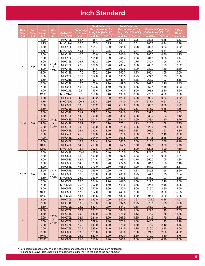
Inch Standard
Hole Diam.
(in)
Rod Diam.
(in)
Free Length
(in)
Wire Size (in)
CATALOG NUMBER
Pounds @ 1/10 inch
defl.
Total Deflection Recommended for
Long Life (20% of C)
Total Deflection Recommended for
Avg. Life (25% of C)Maximum Operating Deflection (35% of C)
* Max. Comp.
Length (in)Load lbs. Defl. in. Load lbs. Defl. in. Load lbs. Defl. in.
1 1/2
1.00
0.125 X
0.214
MHC12L 82.7 165.4 0.20 206.8 0.25 289.5 0.35 0.631.25 MHC12AL 65.3 163.3 0.25 204.1 0.31 285.7 0.44 0.781.50 MHC13L 53.8 161.4 0.30 201.8 0.38 282.5 0.53 0.921.75 MHC13AL 46.1 161.4 0.35 201.7 0.44 282.4 0.61 1.022.00 MHC14L 40.0 160.0 0.40 200.0 0.50 280.0 0.70 1.152.50 MHC15L 32.2 161.0 0.50 201.3 0.63 281.8 0.88 1.443.00 MHC16L 26.7 160.2 0.60 200.3 0.75 280.4 1.05 1.733.50 MHC17L 22.9 160.3 0.70 200.4 0.88 280.5 1.23 2.024.00 MHC18L 20.2 161.6 0.80 202.0 1.00 282.2 1.40 2.304.50 MHC19L 17.8 160.2 0.90 200.3 1.13 280.4 1.58 2.605.00 MHC20L 15.7 157.0 1.00 196.3 1.25 274.8 1.75 2.885.50 MHC21L 13.7 150.7 1.10 188.4 1.38 263.7 1.93 3.166.00 MHC22L 12.5 150.0 1.20 187.5 1.50 262.5 2.10 3.457.00 MHC23L 10.9 152.6 1.40 190.8 1.75 267.1 2.45 4.038.00 MHC24L 9.6 153.6 1.60 192.0 2.00 268.8 2.80 4.6012.00 MHC24AL 6.5 156.0 2.40 195.0 3.00 273.0 4.20 6.80
1 1/4 5/8
1.50
0.165 X
0.270
MHC36L 114.4 343.2 0.30 429.0 0.38 600.6 0.53 0.921.75 MHC36AL 100.8 352.8 0.35 441.0 0.44 617.4 0.61 1.072.00 MHC37L 83.8 335.2 0.40 419.0 0.50 586.6 0.70 1.222.50 MHC38L 62.4 312.0 0.50 390.0 0.63 546.0 0.88 1.553.00 MHC39L 51.2 307.2 0.60 384.0 0.75 537.6 1.05 1.833.50 MHC40L 44.0 308.0 0.70 385.0 0.88 539.0 1.23 2.124.00 MHC41L 38.1 304.8 0.80 381.0 1.00 533.4 1.40 2.494.50 MHC42L 32.9 296.1 0.90 370.1 1.13 518.2 1.58 2.755.00 MHC43L 30.0 300.0 1.00 375.0 1.25 525.0 1.75 3.055.50 MHC44L 26.4 290.4 1.10 363.0 1.38 508.2 1.93 3.306.00 MHC45L 25.0 300.0 1.20 375.0 1.50 525.0 2.10 3.607.00 MHC46L 21.0 294.0 1.40 367.5 1.75 514.5 2.45 4.208.00 MHC47L 18.4 294.4 1.60 368.0 2.00 515.2 2.80 4.9010.00 MHC48L 14.5 290.0 2.00 362.5 2.50 507.5 3.50 5.7812.00 MHC48AL 12.4 297.6 2.40 372.0 3.00 520.8 4.20 7.10
1 1/2 3/4
2.00
0.191 X
0.320
MHC49L 103.0 412.0 0.40 515.0 0.50 721.0 0.70 1.212.50 MHC50L 81.2 406.0 0.50 507.5 0.63 710.5 0.88 1.513.00 MHC51L 62.4 374.4 0.60 468.0 0.75 655.2 1.05 1.853.50 MHC52L 54.0 378.0 0.70 472.5 0.88 661.5 1.23 2.104.00 MHC53L 46.5 372.0 0.80 465.0 1.00 651.0 1.40 2.314.50 MHC54L 41.0 369.0 0.90 461.3 1.13 645.8 1.58 2.605.00 MHC55L 36.8 368.0 1.00 460.0 1.25 644.0 1.75 2.845.50 MHC55AL 33.0 363.0 1.10 453.8 1.38 635.3 1.93 3.106.00 MHC56L 29.5 354.0 1.20 442.5 1.50 619.5 2.10 3.507.00 MHC56AL 25.5 357.0 1.40 446.6 1.75 624.8 2.45 3.958.00 MHC57L 22.0 352.0 1.60 440.0 2.00 616.0 2.80 4.5510.00 MHC58L 17.6 352.0 2.00 440.0 2.50 616.0 3.50 5.5512.00 MHC58AL 14.4 345.6 2.40 432.0 3.00 604.8 4.20 6.85
2 1
2.50
0.235 X
0.440
MHC70L 118.4 592.0 0.50 740.0 0.63 1036.0 0.88 1.533.00 MHC71L 93.0 558.0 0.60 697.5 0.75 976.5 1.05 1.803.50 MHC72L 78.2 547.4 0.70 684.3 0.88 958.0 1.23 2.104.00 MHC73L 66.4 531.2 0.80 664.0 1.00 929.6 1.40 2.354.50 MHC74L 60.0 540.0 0.90 675.0 1.13 945.0 1.58 2.655.00 MHC75L 53.4 534.0 1.00 667.5 1.25 934.5 1.75 2.925.50 MHC76L 49.0 539.0 1.10 673.8 1.38 943.3 1.93 3.186.00 MHC77L 45.0 540.0 1.20 675.0 1.50 945.0 2.10 3.467.00 MHC79L 37.4 523.6 1.40 654.5 1.75 916.3 2.45 4.058.00 MHC80L 33.0 528.0 1.60 660.0 2.00 924.0 2.80 4.6210.00 MHC82L 26.0 520.0 2.00 650.0 2.50 910.0 3.50 5.7512.00 MHC83L 21.5 516.0 2.40 645.0 3.00 903.0 4.20 6.88
* For design purposes only. We do not recommend deflecting a spring to maximum deflection. All springs are available unpainted by adding the suffix “NP” to the end of the part number.
5
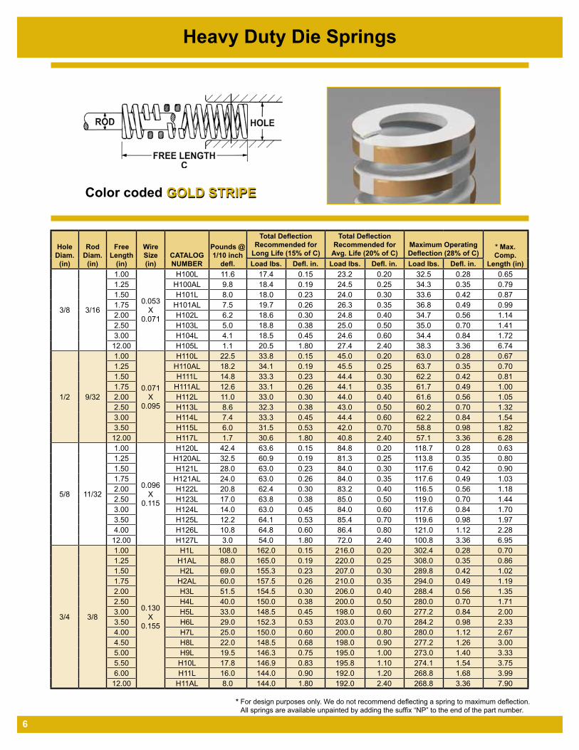
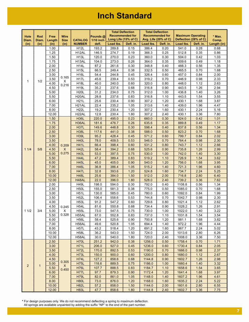
Heavy Duty Die Springs
GOLD STRIPEColor coded GOLD STRIPE
Hole Diam.
(in)
Rod Diam.
(in)
Free Length
(in)
Wire Size (in)
CATALOG NUMBER
Pounds @ 1/10 inch
defl.
Total Deflection Recommended for
Long Life (15% of C)
Total Deflection Recommended for
Avg. Life (20% of C)Maximum Operating Deflection (28% of C)
* Max. Comp.
Length (in)Load lbs. Defl. in. Load lbs. Defl. in. Load lbs. Defl. in.
3/8 3/16
1.00
0.053 X
0.071
H100L 11.6 17.4 0.15 23.2 0.20 32.5 0.28 0.651.25 H100AL 9.8 18.4 0.19 24.5 0.25 34.3 0.35 0.791.50 H101L 8.0 18.0 0.23 24.0 0.30 33.6 0.42 0.871.75 H101AL 7.5 19.7 0.26 26.3 0.35 36.8 0.49 0.992.00 H102L 6.2 18.6 0.30 24.8 0.40 34.7 0.56 1.142.50 H103L 5.0 18.8 0.38 25.0 0.50 35.0 0.70 1.413.00 H104L 4.1 18.5 0.45 24.6 0.60 34.4 0.84 1.72
12.00 H105L 1.1 20.5 1.80 27.4 2.40 38.3 3.36 6.74
1/2 9/32
1.00
0.071 X
0.095
H110L 22.5 33.8 0.15 45.0 0.20 63.0 0.28 0.671.25 H110AL 18.2 34.1 0.19 45.5 0.25 63.7 0.35 0.701.50 H111L 14.8 33.3 0.23 44.4 0.30 62.2 0.42 0.811.75 H111AL 12.6 33.1 0.26 44.1 0.35 61.7 0.49 1.002.00 H112L 11.0 33.0 0.30 44.0 0.40 61.6 0.56 1.052.50 H113L 8.6 32.3 0.38 43.0 0.50 60.2 0.70 1.323.00 H114L 7.4 33.3 0.45 44.4 0.60 62.2 0.84 1.543.50 H115L 6.0 31.5 0.53 42.0 0.70 58.8 0.98 1.82
12.00 H117L 1.7 30.6 1.80 40.8 2.40 57.1 3.36 6.28
5/8 11/32
1.00
0.096 X
0.115
H120L 42.4 63.6 0.15 84.8 0.20 118.7 0.28 0.631.25 H120AL 32.5 60.9 0.19 81.3 0.25 113.8 0.35 0.801.50 H121L 28.0 63.0 0.23 84.0 0.30 117.6 0.42 0.901.75 H121AL 24.0 63.0 0.26 84.0 0.35 117.6 0.49 1.032.00 H122L 20.8 62.4 0.30 83.2 0.40 116.5 0.56 1.182.50 H123L 17.0 63.8 0.38 85.0 0.50 119.0 0.70 1.443.00 H124L 14.0 63.0 0.45 84.0 0.60 117.6 0.84 1.703.50 H125L 12.2 64.1 0.53 85.4 0.70 119.6 0.98 1.974.00 H126L 10.8 64.8 0.60 86.4 0.80 121.0 1.12 2.28
12.00 H127L 3.0 54.0 1.80 72.0 2.40 100.8 3.36 6.95
3/4 3/8
1.00
0.130 X
0.155
H1L 108.0 162.0 0.15 216.0 0.20 302.4 0.28 0.701.25 H1AL 88.0 165.0 0.19 220.0 0.25 308.0 0.35 0.861.50 H2L 69.0 155.3 0.23 207.0 0.30 289.8 0.42 1.021.75 H2AL 60.0 157.5 0.26 210.0 0.35 294.0 0.49 1.192.00 H3L 51.5 154.5 0.30 206.0 0.40 288.4 0.56 1.352.50 H4L 40.0 150.0 0.38 200.0 0.50 280.0 0.70 1.713.00 H5L 33.0 148.5 0.45 198.0 0.60 277.2 0.84 2.003.50 H6L 29.0 152.3 0.53 203.0 0.70 284.2 0.98 2.334.00 H7L 25.0 150.0 0.60 200.0 0.80 280.0 1.12 2.674.50 H8L 22.0 148.5 0.68 198.0 0.90 277.2 1.26 3.005.00 H9L 19.5 146.3 0.75 195.0 1.00 273.0 1.40 3.335.50 H10L 17.8 146.9 0.83 195.8 1.10 274.1 1.54 3.756.00 H11L 16.0 144.0 0.90 192.0 1.20 268.8 1.68 3.99
12.00 H11AL 8.0 144.0 1.80 192.0 2.40 268.8 3.36 7.90
* For design purposes only. We do not recommend deflecting a spring to maximum deflection. All springs are available unpainted by adding the suffix “NP” to the end of the part number.
6
Inch Standard
Hole Diam.
(in)
Rod Diam.
(in)
Free Length
(in)
Wire Size (in)
CATALOG NUMBER
Pounds @ 1/10 inch
defl.
Total Deflection Recommended for
Long Life (15% of C)
Total Deflection Recommended for
Avg. Life (20% of C)Maximum Operating Deflection (28% of C)
* Max. Comp.
Length (in)Load lbs. Defl. in. Load lbs. Defl. in. Load lbs. Defl. in.
1 1/2
1.00
0.165 X
0.216
H12L 193.2 289.8 0.15 386.4 0.20 541.0 0.28 0.681.25 H12AL 146.5 274.7 0.19 366.3 0.25 512.8 0.35 0.861.50 H13L 120.0 270.0 0.23 360.0 0.30 504.0 0.42 1.031.75 H13AL 104.0 273.0 0.26 364.0 0.35 509.6 0.49 1.182.00 H14L 87.2 261.6 0.30 348.8 0.40 488.3 0.56 1.352.50 H15L 66.5 249.4 0.38 332.5 0.50 465.5 0.70 1.683.00 H16L 54.4 244.8 0.45 326.4 0.60 457.0 0.84 2.003.50 H17L 45.6 239.4 0.53 319.2 0.70 446.9 0.98 2.334.00 H18L 40.0 240.0 0.60 320.0 0.80 448.0 1.12 2.634.50 H19L 35.2 237.6 0.68 316.8 0.90 443.5 1.26 2.945.00 H20L 31.2 234.0 0.75 312.0 1.00 436.8 1.40 3.265.50 H20AL 28.8 237.6 0.83 316.8 1.10 443.5 1.54 3.556.00 H21L 25.6 230.4 0.90 307.2 1.20 430.1 1.68 3.877.00 H21AL 22.4 235.2 1.05 313.6 1.40 439.0 1.96 4.478.00 H22L 19.2 230.4 1.20 307.2 1.60 430.1 2.24 5.16
12.00 H22AL 12.8 230.4 1.80 307.2 2.40 430.1 3.36 7.80
1 1/4 5/8
1.50
0.209 X
0.275
H36L 220.0 495.0 0.23 660.0 0.30 924.0 0.42 1.011.75 H36AL 181.6 476.7 0.26 635.6 0.35 889.8 0.49 1.172.00 H37L 149.6 448.8 0.30 598.4 0.40 837.8 0.56 1.342.50 H38L 117.6 441.0 0.38 588.0 0.50 823.2 0.70 1.683.00 H39L 95.2 428.4 0.45 571.2 0.60 799.7 0.84 2.023.50 H40L 78.0 409.5 0.53 546.0 0.70 764.4 0.98 2.304.00 H41L 66.4 398.4 0.60 531.2 0.80 743.7 1.12 2.664.50 H42L 58.4 394.2 0.68 525.6 0.90 735.8 1.26 2.995.00 H43L 53.0 397.5 0.75 530.0 1.00 742.0 1.40 3.305.50 H44L 47.2 389.4 0.83 519.2 1.10 726.9 1.54 3.626.00 H45L 45.0 405.0 0.90 540.0 1.20 756.0 1.68 3.957.00 H46L 36.8 386.4 1.05 515.2 1.40 721.3 1.96 4.608.00 H47L 32.8 393.6 1.20 524.8 1.60 734.7 2.24 5.25
10.00 H48L 25.6 384.0 1.50 512.0 2.00 716.8 2.80 6.4012.00 H48AL 22.0 396.0 1.80 528.0 2.40 739.2 3.36 7.62
1 1/2 3/4
2.00
0.245 X
0.328
H49L 198.0 594.0 0.30 792.0 0.40 1108.8 0.56 1.342.50 H50L 155.0 581.3 0.38 775.0 0.50 1085.0 0.70 1.683.00 H51L 130.0 585.0 0.45 780.0 0.60 1092.0 0.84 1.993.50 H52L 106.4 558.6 0.53 744.8 0.70 1042.7 0.98 2.304.00 H53L 91.2 547.2 0.60 729.6 0.80 1021.4 1.12 2.624.50 H54L 81.6 550.8 0.68 734.4 0.90 1028.2 1.26 2.915.00 H55L 73.0 547.5 0.75 730.0 1.00 1022.0 1.40 3.225.50 H55AL 67.0 552.8 0.83 737.0 1.10 1031.8 1.54 3.546.00 H56L 58.4 525.6 0.90 700.8 1.20 981.1 1.68 3.827.00 H56AL 49.6 520.8 1.05 694.4 1.40 972.2 1.96 4.448.00 H57L 43.2 518.4 1.20 691.2 1.60 967.7 2.24 5.02
10.00 H58L 36.2 543.0 1.50 724.0 2.00 1013.6 2.80 6.2612.00 H58AL 30.0 540.0 1.80 720.0 2.40 1008.0 3.36 7.50
2 1
2.50
0.305 X
0.450
H70L 251.2 942.0 0.38 1256.0 0.50 1758.4 0.70 1.713.00 H71L 206.0 927.0 0.45 1236.0 0.60 1730.4 0.84 2.053.50 H72L 170.0 892.5 0.53 1190.0 0.70 1666.0 0.98 2.374.00 H73L 150.0 900.0 0.60 1200.0 0.80 1680.0 1.12 2.674.50 H74L 127.2 858.6 0.68 1144.8 0.90 1602.7 1.26 2.985.00 H75L 118.6 889.5 0.75 1186.0 1.00 1660.4 1.40 3.325.50 H76L 107.7 888.5 0.83 1184.7 1.10 1658.6 1.54 3.656.00 H77L 97.7 879.3 0.90 1172.4 1.20 1641.4 1.68 3.977.00 H79L 82.0 861.0 1.05 1148.0 1.40 1607.2 1.96 4.618.00 H80L 73.0 876.0 1.20 1168.0 1.60 1635.2 2.24 5.22
10.00 H82L 57.2 858.0 1.50 1144.0 2.00 1601.6 2.80 6.5512.00 H83L 47.7 858.6 1.80 1144.8 2.40 1602.7 3.36 7.75
* For design purposes only. We do not recommend deflecting a spring to maximum deflection. All springs are available unpainted by adding the suffix “NP” to the end of the part number.
7
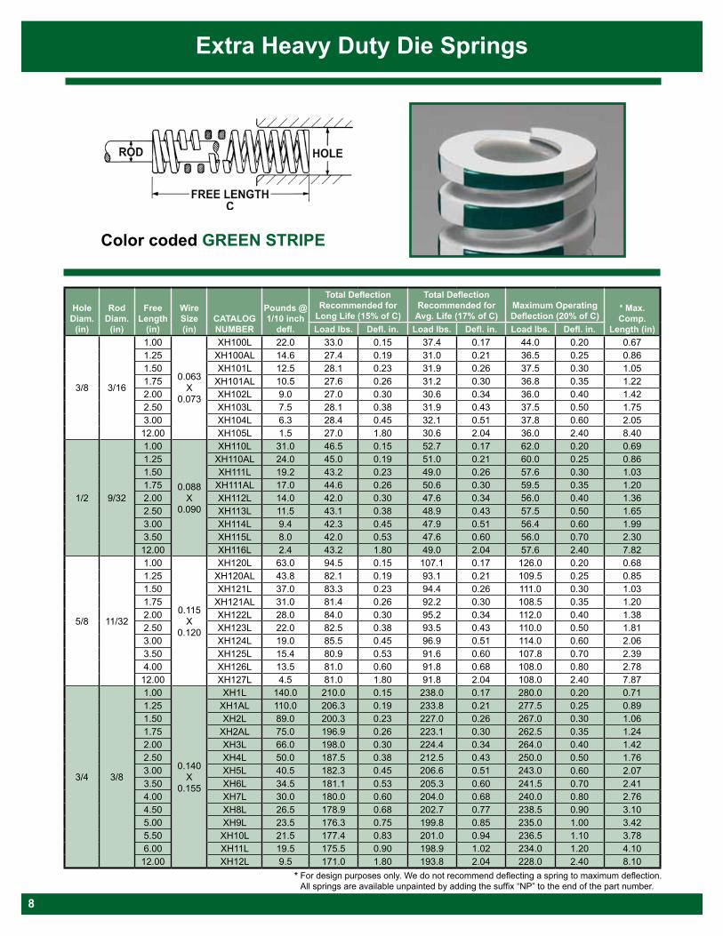
Color coded GREEN STRIPE
Extra Heavy Duty Die Springs
Hole Diam.
(in)
Rod Diam.
(in)
Free Length
(in)
Wire Size (in)
CATALOG NUMBER
Pounds @ 1/10 inch
defl.
Total Deflection Recommended for
Long Life (15% of C)
Total Deflection Recommended for
Avg. Life (17% of C)Maximum Operating Deflection (20% of C)
* Max. Comp.
Length (in)Load lbs. Defl. in. Load lbs. Defl. in. Load lbs. Defl. in.
3/8 3/16
1.00
0.063 X
0.073
XH100L 22.0 33.0 0.15 37.4 0.17 44.0 0.20 0.671.25 XH100AL 14.6 27.4 0.19 31.0 0.21 36.5 0.25 0.861.50 XH101L 12.5 28.1 0.23 31.9 0.26 37.5 0.30 1.051.75 XH101AL 10.5 27.6 0.26 31.2 0.30 36.8 0.35 1.222.00 XH102L 9.0 27.0 0.30 30.6 0.34 36.0 0.40 1.422.50 XH103L 7.5 28.1 0.38 31.9 0.43 37.5 0.50 1.753.00 XH104L 6.3 28.4 0.45 32.1 0.51 37.8 0.60 2.0512.00 XH105L 1.5 27.0 1.80 30.6 2.04 36.0 2.40 8.40
1/2 9/32
1.00
0.088 X
0.090
XH110L 31.0 46.5 0.15 52.7 0.17 62.0 0.20 0.691.25 XH110AL 24.0 45.0 0.19 51.0 0.21 60.0 0.25 0.861.50 XH111L 19.2 43.2 0.23 49.0 0.26 57.6 0.30 1.031.75 XH111AL 17.0 44.6 0.26 50.6 0.30 59.5 0.35 1.202.00 XH112L 14.0 42.0 0.30 47.6 0.34 56.0 0.40 1.362.50 XH113L 11.5 43.1 0.38 48.9 0.43 57.5 0.50 1.653.00 XH114L 9.4 42.3 0.45 47.9 0.51 56.4 0.60 1.993.50 XH115L 8.0 42.0 0.53 47.6 0.60 56.0 0.70 2.3012.00 XH116L 2.4 43.2 1.80 49.0 2.04 57.6 2.40 7.82
5/8 11/32
1.00
0.115 X
0.120
XH120L 63.0 94.5 0.15 107.1 0.17 126.0 0.20 0.681.25 XH120AL 43.8 82.1 0.19 93.1 0.21 109.5 0.25 0.851.50 XH121L 37.0 83.3 0.23 94.4 0.26 111.0 0.30 1.031.75 XH121AL 31.0 81.4 0.26 92.2 0.30 108.5 0.35 1.202.00 XH122L 28.0 84.0 0.30 95.2 0.34 112.0 0.40 1.382.50 XH123L 22.0 82.5 0.38 93.5 0.43 110.0 0.50 1.813.00 XH124L 19.0 85.5 0.45 96.9 0.51 114.0 0.60 2.063.50 XH125L 15.4 80.9 0.53 91.6 0.60 107.8 0.70 2.394.00 XH126L 13.5 81.0 0.60 91.8 0.68 108.0 0.80 2.7812.00 XH127L 4.5 81.0 1.80 91.8 2.04 108.0 2.40 7.87
3/4 3/8
1.00
0.140 X
0.155
XH1L 140.0 210.0 0.15 238.0 0.17 280.0 0.20 0.711.25 XH1AL 110.0 206.3 0.19 233.8 0.21 277.5 0.25 0.891.50 XH2L 89.0 200.3 0.23 227.0 0.26 267.0 0.30 1.061.75 XH2AL 75.0 196.9 0.26 223.1 0.30 262.5 0.35 1.242.00 XH3L 66.0 198.0 0.30 224.4 0.34 264.0 0.40 1.422.50 XH4L 50.0 187.5 0.38 212.5 0.43 250.0 0.50 1.763.00 XH5L 40.5 182.3 0.45 206.6 0.51 243.0 0.60 2.073.50 XH6L 34.5 181.1 0.53 205.3 0.60 241.5 0.70 2.414.00 XH7L 30.0 180.0 0.60 204.0 0.68 240.0 0.80 2.764.50 XH8L 26.5 178.9 0.68 202.7 0.77 238.5 0.90 3.105.00 XH9L 23.5 176.3 0.75 199.8 0.85 235.0 1.00 3.425.50 XH10L 21.5 177.4 0.83 201.0 0.94 236.5 1.10 3.786.00 XH11L 19.5 175.5 0.90 198.9 1.02 234.0 1.20 4.1012.00 XH12L 9.5 171.0 1.80 193.8 2.04 228.0 2.40 8.10
* For design purposes only. We do not recommend deflecting a spring to maximum deflection. All springs are available unpainted by adding the suffix “NP” to the end of the part number.
8
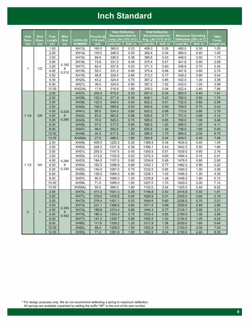
Inch Standard
Hole Diam.
(in)
Rod Diam.
(in)
Free Length
(in)
Wire Size (in)
CATALOG NUMBER
Pounds @ 1/10 inch
defl.
Total Deflection Recommended for
Long Life (15% of C)
Total Deflection Recommended for
Avg. Life (17% of C)Maximum Operating Deflection (20% of C)
* Max. Comp.
Length (in)Load lbs. Defl. in. Load lbs. Defl. in. Load lbs. Defl. in.
1 1/2
1.50
0.182 X
0.215
XH13L 160.0 360.0 0.23 408.0 0.26 480.0 0.30 1.052.00 XH14L 116.0 348.0 0.30 394.4 0.34 464.0 0.40 1.402.50 XH15L 89.6 336.0 0.38 380.8 0.43 448.0 0.50 1.733.00 XH16L 73.6 331.2 0.45 375.4 0.51 441.6 0.60 2.083.50 XH17L 62.4 327.6 0.53 371.3 0.60 436.8 0.70 2.424.00 XH18L 55.2 331.2 0.60 375.4 0.68 441.6 0.80 2.744.50 XH19L 48.8 329.4 0.68 373.3 0.77 439.2 0.90 3.045.00 XH20L 43.2 324.0 0.75 367.2 0.85 432.0 1.00 3.386.00 XH21L 36.0 324.0 0.90 367.2 1.02 432.0 1.20 3.9912.00 XH22AL 17.6 316.8 1.80 359.0 2.04 422.4 2.40 7.86
1 1/4 5/8
2.00
0.226 X
0.280
XH37L 205.0 615.0 0.30 697.0 0.34 820.0 0.40 1.412.50 XH38L 152.5 571.9 0.38 648.1 0.43 762.5 0.50 1.743.00 XH39L 122.0 549.0 0.45 622.2 0.51 732.0 0.60 2.093.50 XH40L 108.5 569.6 0.53 645.6 0.60 759.5 0.70 2.434.00 XH41L 89.0 534.0 0.60 605.2 0.68 712.0 0.80 2.784.50 XH42L 83.5 563.6 0.68 638.8 0.77 751.5 0.90 3.125.00 XH43L 70.0 525.0 0.75 595.0 0.85 700.0 1.00 3.466.00 XH45L 57.5 517.5 0.90 586.5 1.02 690.0 1.20 4.118.00 XH47L 46.0 552.0 1.20 625.6 1.36 736.0 1.60 5.4010.00 XH48L 34.5 517.5 1.50 586.5 1.70 690.0 2.00 6.7512.00 XH48AL 27.0 486.0 1.80 550.8 2.04 648.0 2.40 7.99
1 1/2 3/4
2.00
0.290 X
0.330
XH49L 408.5 1225.5 0.30 1388.9 0.34 1634.0 0.40 1.452.50 XH50L 328.5 1231.9 0.38 1396.1 0.43 1642.5 0.50 1.803.00 XH51L 255.0 1147.5 0.45 1300.5 0.51 1530.0 0.60 2.163.50 XH52L 213.5 1120.9 0.53 1270.3 0.60 1494.5 0.70 2.514.00 XH53L 184.5 1107.0 0.60 1254.6 0.68 1476.0 0.80 2.904.50 XH54L 162.5 1096.9 0.68 1243.1 0.77 1462.5 0.90 3.225.00 XH55L 145.0 1087.5 0.75 1232.5 0.85 1450.0 1.00 3.586.00 XH56L 120.5 1084.5 0.90 1229.1 1.02 1446.0 1.20 4.308.00 XH57L 90.5 1086.0 1.20 1230.8 1.36 1448.0 1.60 5.7210.00 XH58L 71.0 1065.0 1.50 1207.0 1.70 1420.0 2.00 7.1212.00 XH58AL 55.0 990.0 1.80 1122.0 2.04 1320.0 2.40 8.52
2 1
2.50
0.350 X
0.452
XH70L 411.0 1541.3 0.38 1746.8 0.43 2418.8 0.50 1.813.00 XH71L 319.0 1435.5 0.45 1626.9 0.51 2340.0 0.60 2.163.50 XH72L 276.4 1451.1 0.53 1644.6 0.60 2226.0 0.70 2.514.00 XH73L 231.1 1386.6 0.60 1571.5 0.68 2200.0 0.80 2.864.50 XH74L 188.8 1274.4 0.68 1444.3 0.77 2134.1 0.90 3.215.00 XH75L 180.4 1353.0 0.75 1533.4 0.85 2160.0 1.00 3.566.00 XH77L 147.3 1325.7 0.90 1502.5 1.02 2124.0 1.20 4.248.00 XH80L 111.6 1339.2 1.20 1517.8 1.36 2030.0 1.60 5.6410.00 XH82L 88.4 1326.0 1.50 1502.8 1.70 2100.0 2.00 7.0212.00 XH83L 71.2 1281.6 1.80 1452.5 2.04 2100.0 2.40 8.35
* For design purposes only. We do not recommend deflecting a spring to maximum deflection. All springs are available unpainted by adding the suffix “NP” to the end of the part number.
9
10
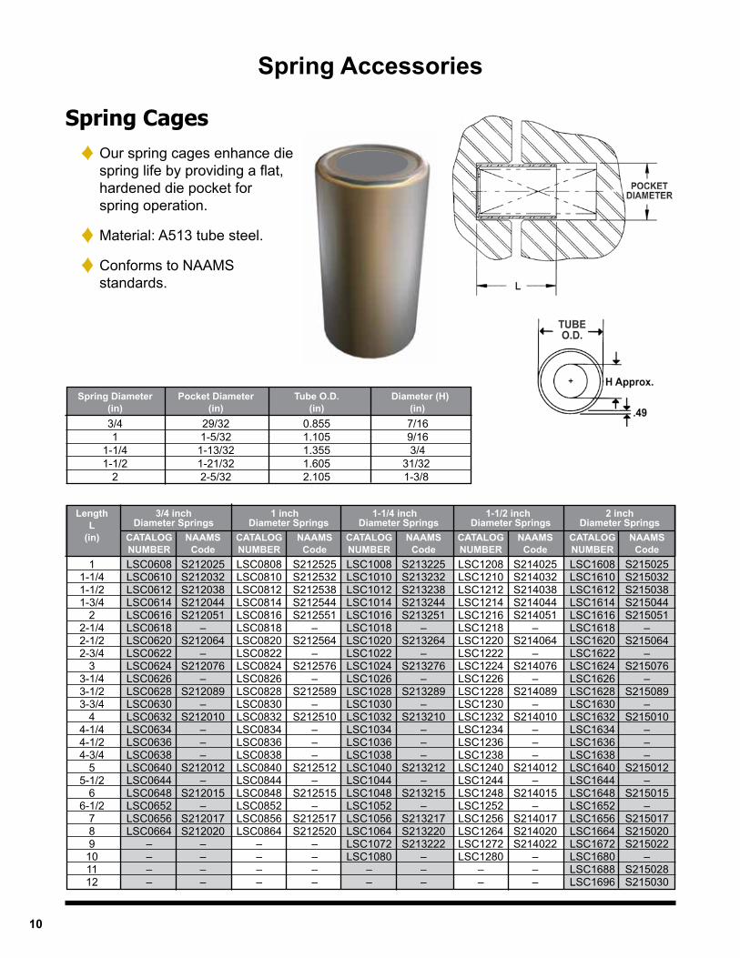
Spring Accessories
Spring Cages ♦ Our spring cages enhance die spring life by providing a flat, hardened die pocket for spring operation.
♦ Material: A513 tube steel.
♦ Conforms to NAAMS standards.
Spring Diameter Pocket Diameter Tube O.D. Diameter (H) (in) (in) (in) (in) 3/4 29/32 0.855 7/16 1 1-5/32 1.105 9/16 1-1/4 1-13/32 1.355 3/4 1-1/2 1-21/32 1.605 31/32 2 2-5/32 2.105 1-3/8
Length 3/4 inch 1 inch 1-1/4 inch 1-1/2 inch 2 inch L Diameter Springs Diameter Springs Diameter Springs Diameter Springs Diameter Springs (in) CATALOG NAAMS CATALOG NAAMS CATALOG NAAMS CATALOG NAAMS CATALOG NAAMS NUMBER Code NUMBER Code NUMBER Code NUMBER Code NUMBER Code 1 LSC0608 S212025 LSC0808 S212525 LSC1008 S213225 LSC1208 S214025 LSC1608 S215025 1-1/4 LSC0610 S212032 LSC0810 S212532 LSC1010 S213232 LSC1210 S214032 LSC1610 S215032 1-1/2 LSC0612 S212038 LSC0812 S212538 LSC1012 S213238 LSC1212 S214038 LSC1612 S215038 1-3/4 LSC0614 S212044 LSC0814 S212544 LSC1014 S213244 LSC1214 S214044 LSC1614 S215044 2 LSC0616 S212051 LSC0816 S212551 LSC1016 S213251 LSC1216 S214051 LSC1616 S215051 2-1/4 LSC0618 – LSC0818 – LSC1018 – LSC1218 – LSC1618 – 2-1/2 LSC0620 S212064 LSC0820 S212564 LSC1020 S213264 LSC1220 S214064 LSC1620 S215064 2-3/4 LSC0622 – LSC0822 – LSC1022 – LSC1222 – LSC1622 – 3 LSC0624 S212076 LSC0824 S212576 LSC1024 S213276 LSC1224 S214076 LSC1624 S215076 3-1/4 LSC0626 – LSC0826 – LSC1026 – LSC1226 – LSC1626 – 3-1/2 LSC0628 S212089 LSC0828 S212589 LSC1028 S213289 LSC1228 S214089 LSC1628 S215089 3-3/4 LSC0630 – LSC0830 – LSC1030 – LSC1230 – LSC1630 – 4 LSC0632 S212010 LSC0832 S212510 LSC1032 S213210 LSC1232 S214010 LSC1632 S215010 4-1/4 LSC0634 – LSC0834 – LSC1034 – LSC1234 – LSC1634 – 4-1/2 LSC0636 – LSC0836 – LSC1036 – LSC1236 – LSC1636 – 4-3/4 LSC0638 – LSC0838 – LSC1038 – LSC1238 – LSC1638 – 5 LSC0640 S212012 LSC0840 S212512 LSC1040 S213212 LSC1240 S214012 LSC1640 S215012 5-1/2 LSC0644 – LSC0844 – LSC1044 – LSC1244 – LSC1644 – 6 LSC0648 S212015 LSC0848 S212515 LSC1048 S213215 LSC1248 S214015 LSC1648 S215015 6-1/2 LSC0652 – LSC0852 – LSC1052 – LSC1252 – LSC1652 – 7 LSC0656 S212017 LSC0856 S212517 LSC1056 S213217 LSC1256 S214017 LSC1656 S215017 8 LSC0664 S212020 LSC0864 S212520 LSC1064 S213220 LSC1264 S214020 LSC1664 S215020 9 – – – – LSC1072 S213222 LSC1272 S214022 LSC1672 S215022 10 – – – – LSC1080 – LSC1280 – LSC1680 – 11 – – – – – – – – LSC1688 S215028 12 – – – – – – – – LSC1696 S215030
11
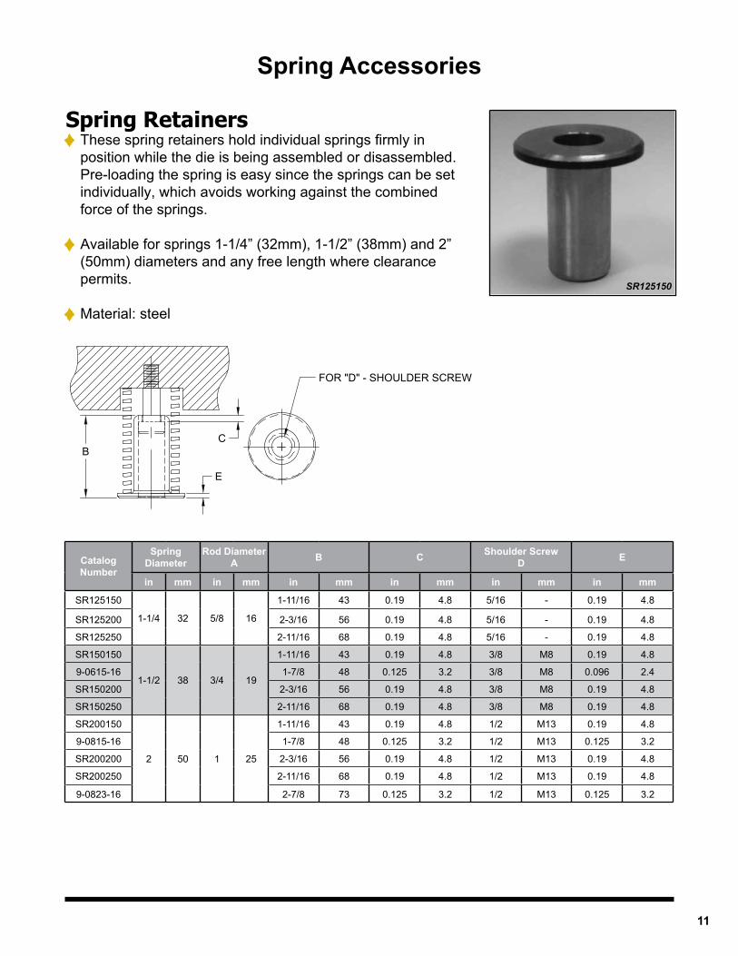
Spring Retainers♦ These spring retainers hold individual springs firmly in
position while the die is being assembled or disassembled. Pre-loading the spring is easy since the springs can be set individually, which avoids working against the combined force of the springs.
♦ Available for springs 1-1/4” (32mm), 1-1/2” (38mm) and 2” (50mm) diameters and any free length where clearance permits.
♦ Material: steel
Spring Accessories
SR125150
B
E
FOR "D" - SHOULDER SCREW
C
Catalog Number
Spring Diameter
Rod Diameter A B C Shoulder Screw
D E
in mm in mm in mm in mm in mm in mm
SR125150
1-1/4 32 5/8 16
1-11/16 43 0.19 4.8 5/16 - 0.19 4.8
SR125200 2-3/16 56 0.19 4.8 5/16 - 0.19 4.8
SR125250 2-11/16 68 0.19 4.8 5/16 - 0.19 4.8
SR150150
1-1/2 38 3/4 19
1-11/16 43 0.19 4.8 3/8 M8 0.19 4.8
9-0615-16 1-7/8 48 0.125 3.2 3/8 M8 0.096 2.4
SR150200 2-3/16 56 0.19 4.8 3/8 M8 0.19 4.8
SR150250 2-11/16 68 0.19 4.8 3/8 M8 0.19 4.8
SR200150
2 50 1 25
1-11/16 43 0.19 4.8 1/2 M13 0.19 4.8
9-0815-16 1-7/8 48 0.125 3.2 1/2 M13 0.125 3.2
SR200200 2-3/16 56 0.19 4.8 1/2 M13 0.19 4.8
SR200250 2-11/16 68 0.19 4.8 1/2 M13 0.19 4.8
9-0823-16 2-7/8 73 0.125 3.2 1/2 M13 0.125 3.2
12
♦ Submit custom spring print♦ Submit application information Include description of application Life expectations Critical dimensions, tolerances, certifications required
SPRING SPECIALS QUOTING PROCESS
Special Heavy Duty Compression Springs
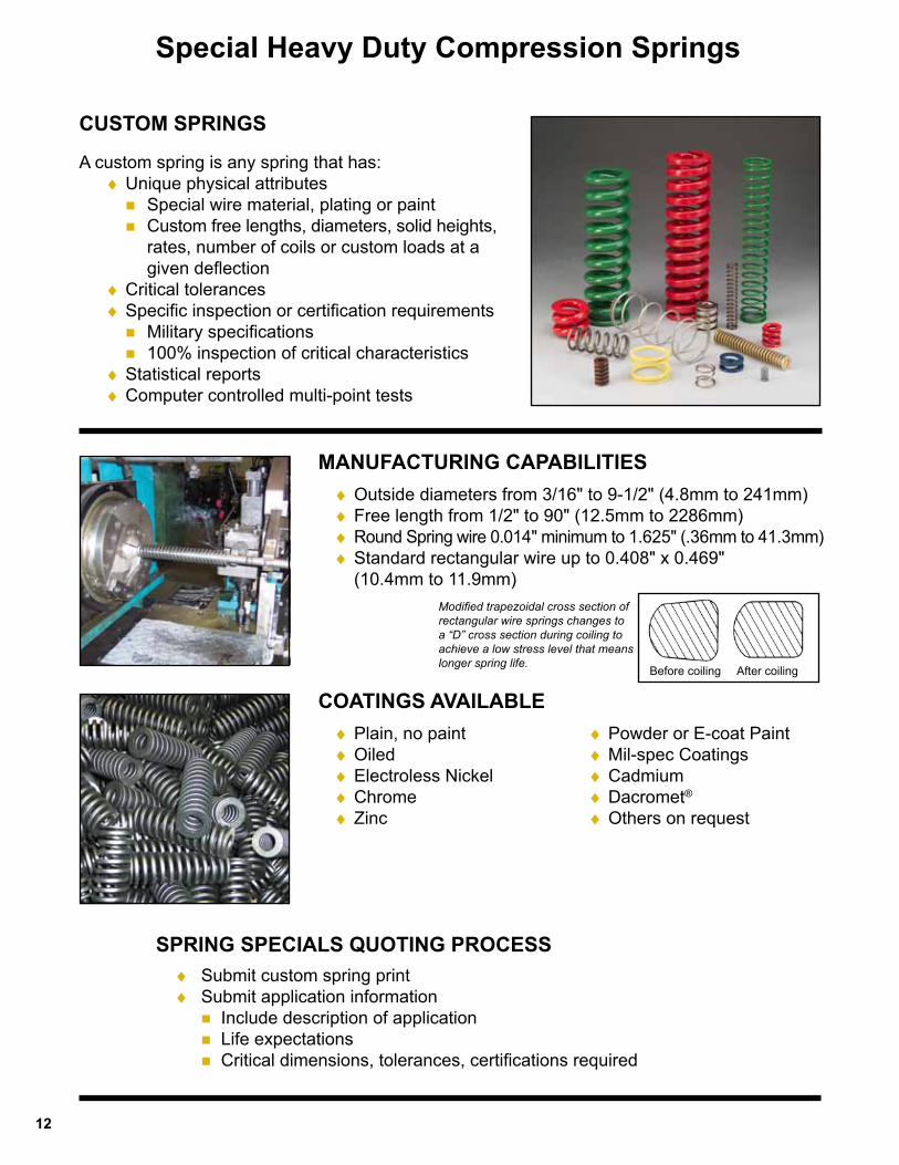
MANUFACTURING CAPABILITIES
A custom spring is any spring that has: ♦Unique physical attributes Special wire material, plating or paint Custom free lengths, diameters, solid heights, rates, number of coils or custom loads at a given deflection ♦Critical tolerances ♦Specific inspection or certification requirements Military specifications 100% inspection of critical characteristics ♦Statistical reports ♦Computer controlled multi-point tests
♦Outside diameters from 3/16" to 9-1/2" (4.8mm to 241mm) ♦Free length from 1/2" to 90" (12.5mm to 2286mm) ♦Round Spring wire 0.014" minimum to 1.625" (.36mm to 41.3mm) ♦Standard rectangular wire up to 0.408" x 0.469" (10.4mm to 11.9mm)
CUSTOM SPRINGS
♦Plain, no paint ♦Oiled ♦Electroless Nickel ♦Chrome ♦Zinc
COATINGS AVAILABLE
Modified trapezoidal cross section of rectangular wire springs changes to a “D” cross section during coiling to achieve a low stress level that means longer spring life.
Before coiling After coiling
♦Powder or E-coat Paint ♦Mil-spec Coatings ♦Cadmium ♦Dacromet®
♦Others on request
13
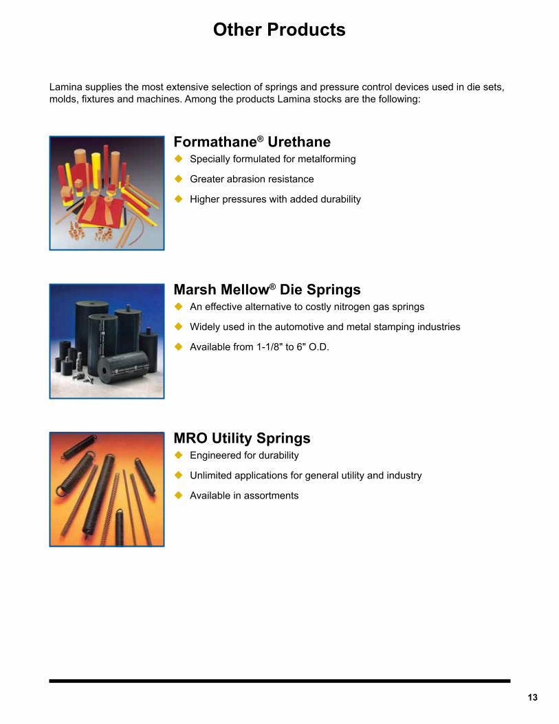
Lamina supplies the most extensive selection of springs and pressure control devices used in die sets, molds, fixtures and machines. Among the products Lamina stocks are the following:
Formathane® UrethaneSpecially formulated for metalforming
Greater abrasion resistance
Higher pressures with added durability
MRO Utility SpringsEngineered for durability
Unlimited applications for general utility and industry
Available in assortments
Marsh Mellow® Die SpringsAn effective alternative to costly nitrogen gas springs
Widely used in the automotive and metal stamping industries
Available from 1-1/8" to 6" O.D.
Other Products
© 2018 Dayton Lamina Corporation. All rights reserved.
Commitment to Quality & Customer Satisfaction
Dayton Lamina is a leading manufacturer of tool, die and mold components for the metal-working and plastics industries. As a customer-focused, world-class supplier of choice, we provide the brands, product breadth, distribution network and technical support for all your metal forming needs.
Our goal is to give our customers the most innovative and value-added products and services.
www.daytonlamina.com
*
*Dayton Lamina’s line of Danly products is available only to North America.
004 9/18