DIE CUSHIONS CATALOG
42
Transcript of DIE CUSHIONS CATALOG
DAYTON DIE CUSHIONSDAYTON DIE CUSHIONSDAYTON DIE CUSHIONSDAYTON DIE CUSHIONS
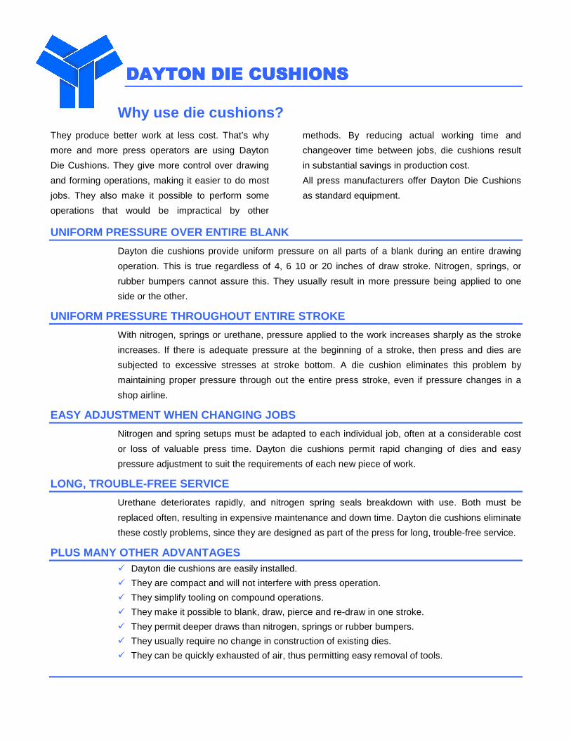
Why use die cushions? They produce better work at less cost. That’s why
more and more press operators are using Dayton
Die Cushions. They give more control over drawing
and forming operations, making it easier to do most
jobs. They also make it possible to perform some
operations that would be impractical by other
methods. By reducing actual working time and
changeover time between jobs, die cushions result
in substantial savings in production cost.
All press manufacturers offer Dayton Die Cushions
as standard equipment.
UNIFORM PRESSURE OVER ENTIRE BLANK
Dayton die cushions provide uniform pressure on all parts of a blank during an entire drawing
operation. This is true regardless of 4, 6 10 or 20 inches of draw stroke. Nitrogen, springs, or
rubber bumpers cannot assure this. They usually result in more pressure being applied to one
side or the other.
UNIFORM PRESSURE THROUGHOUT ENTIRE STROKE
With nitrogen, springs or urethane, pressure applied to the work increases sharply as the stroke
increases. If there is adequate pressure at the beginning of a stroke, then press and dies are
subjected to excessive stresses at stroke bottom. A die cushion eliminates this problem by
maintaining proper pressure through out the entire press stroke, even if pressure changes in a
shop airline.
EASY ADJUSTMENT WHEN CHANGING JOBS
Nitrogen and spring setups must be adapted to each individual job, often at a considerable cost
or loss of valuable press time. Dayton die cushions permit rapid changing of dies and easy
pressure adjustment to suit the requirements of each new piece of work.
LONG, TROUBLE-FREE SERVICE
Urethane deteriorates rapidly, and nitrogen spring seals breakdown with use. Both must be
replaced often, resulting in expensive maintenance and down time. Dayton die cushions eliminate
these costly problems, since they are designed as part of the press for long, trouble-free service.
PLUS MANY OTHER ADVANTAGES � Dayton die cushions are easily installed.
� They are compact and will not interfere with press operation.
� They simplify tooling on compound operations.
� They make it possible to blank, draw, pierce and re-draw in one stroke.
� They permit deeper draws than nitrogen, springs or rubber bumpers.
� They usually require no change in construction of existing dies.
� They can be quickly exhausted of air, thus permitting easy removal of tools.
DAYTON DIE CUSHIONSDAYTON DIE CUSHIONSDAYTON DIE CUSHIONSDAYTON DIE CUSHIONS
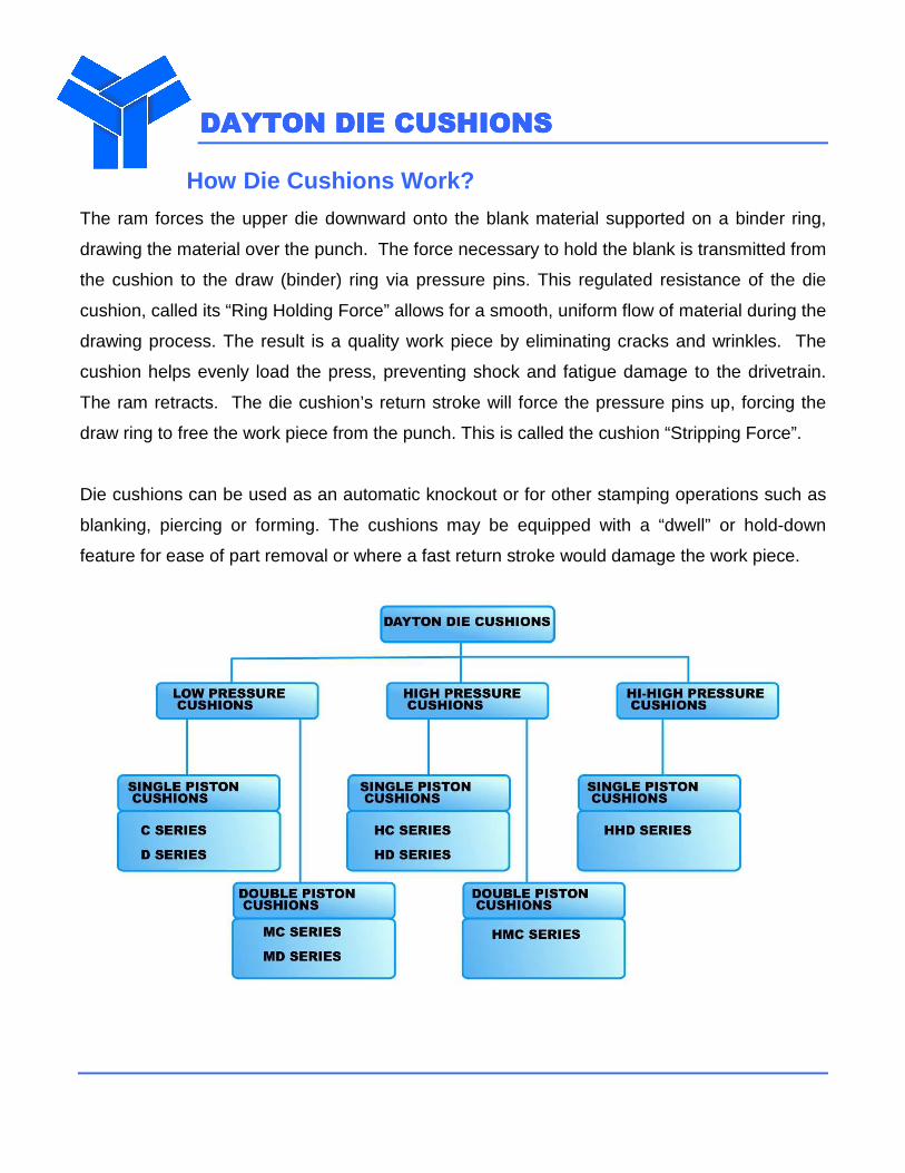
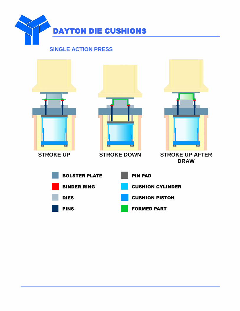
How Die Cushions Work?
The ram forces the upper die downward onto the blank material supported on a binder ring,
drawing the material over the punch. The force necessary to hold the blank is transmitted from
the cushion to the draw (binder) ring via pressure pins. This regulated resistance of the die
cushion, called its “Ring Holding Force” allows for a smooth, uniform flow of material during the
drawing process. The result is a quality work piece by eliminating cracks and wrinkles. The
cushion helps evenly load the press, preventing shock and fatigue damage to the drivetrain.
The ram retracts. The die cushion’s return stroke will force the pressure pins up, forcing the
draw ring to free the work piece from the punch. This is called the cushion “Stripping Force”.
Die cushions can be used as an automatic knockout or for other stamping operations such as
blanking, piercing or forming. The cushions may be equipped with a “dwell” or hold-down
feature for ease of part removal or where a fast return stroke would damage the work piece.
DAYTON DIE CUSHIONSDAYTON DIE CUSHIONSDAYTON DIE CUSHIONSDAYTON DIE CUSHIONS
SINGLE ACTION PRESS
STROKE UP
STROKE DOWN
STROKE UP AFTER
DRAW
BOLSTER PLATE
BINDER RING
DIES
PINS
PIN PAD
CUSHION CYLINDER
CUSHION PISTON
FORMED PART
DAYTON DIE CUSHIONSDAYTON DIE CUSHIONSDAYTON DIE CUSHIONSDAYTON DIE CUSHIONS
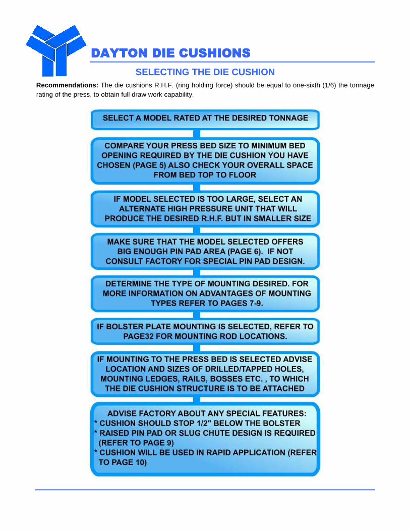
SELECTING THE DIE CUSHION Recommendations: The die cushions R.H.F. (ring holding force) should be equal to one-sixth (1/6) the tonnage rating of the press, to obtain full draw work capability.
DAYTON DIE CDAYTON DIE CDAYTON DIE CDAYTON DIE CUSHIONSUSHIONSUSHIONSUSHIONS
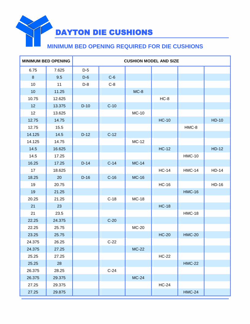
MINIMUM BED OPENING REQUIRED FOR DIE CUSHIONS
MINIMUM BED OPENING CUSHION MODEL AND SIZE
6.75 7.625 D-5
8 9.5 D-6 C-6
10 11 D-8 C-8
10 11.25 MC-8
10.75 12.625 HC-8
12 13.375 D-10 C-10
12 13.625 MC-10
12.75 14.75 HC-10 HD-10
12.75 15.5 HMC-8
14.125 14.5 D-12 C-12
14.125 14.75 MC-12
14.5 16.625 HC-12 HD-12
14.5 17.25 HMC-10
16.25 17.25 D-14 C-14 MC-14
17 18.625 HC-14 HMC-14 HD-14
18.25 20 D-16 C-16 MC-16
19 20.75 HC-16 HD-16
19 21.25 HMC-16
20.25 21.25 C-18 MC-18
21 23 HC-18
21 23.5 HMC-18
22.25 24.375 C-20
22.25 25.75 MC-20
23.25 25.75 HC-20 HMC-20
24.375 26.25 C-22
24.375 27.25 MC-22
25.25 27.25 HC-22
25.25 28 HMC-22
26.375 28.25 C-24
26.375 29.375 MC-24
27.25 29.375 HC-24
27.25 29.875 HMC-24
DAYTON DIE CUSHIONSDAYTON DIE CUSHIONSDAYTON DIE CUSHIONSDAYTON DIE CUSHIONS
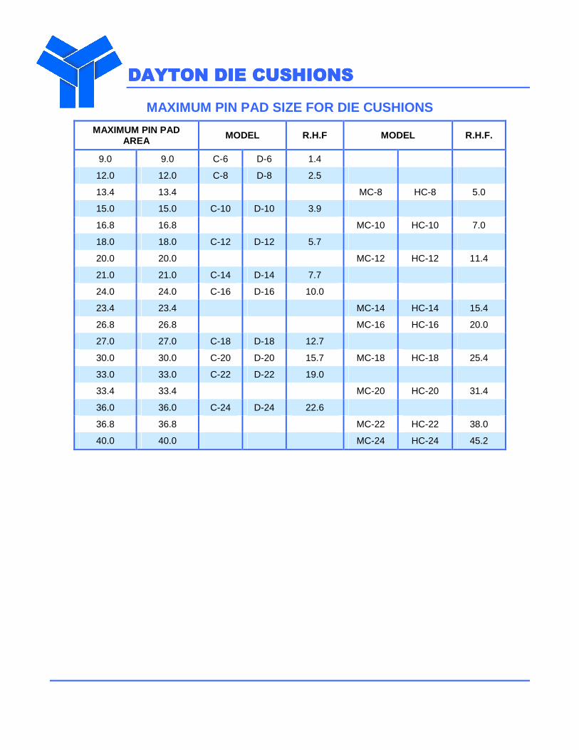
MAXIMUM PIN PAD SIZE FOR DIE CUSHIONS
MAXIMUM PIN PAD AREA MODEL R.H.F MODEL R.H.F.
9.0 9.0 C-6 D-6 1.4
12.0 12.0 C-8 D-8 2.5
13.4 13.4 MC-8 HC-8 5.0
15.0 15.0 C-10 D-10 3.9
16.8 16.8 MC-10 HC-10 7.0
18.0 18.0 C-12 D-12 5.7
20.0 20.0 MC-12 HC-12 11.4
21.0 21.0 C-14 D-14 7.7
24.0 24.0 C-16 D-16 10.0
23.4 23.4 MC-14 HC-14 15.4
26.8 26.8 MC-16 HC-16 20.0
27.0 27.0 C-18 D-18 12.7
30.0 30.0 C-20 D-20 15.7 MC-18 HC-18 25.4
33.0 33.0 C-22 D-22 19.0
33.4 33.4 MC-20 HC-20 31.4
36.0 36.0 C-24 D-24 22.6
36.8 36.8 MC-22 HC-22 38.0
40.0 40.0 MC-24 HC-24 45.2
DAYTON DIE CUSHIONSDAYTON DIE CUSHIONSDAYTON DIE CUSHIONSDAYTON DIE CUSHIONS
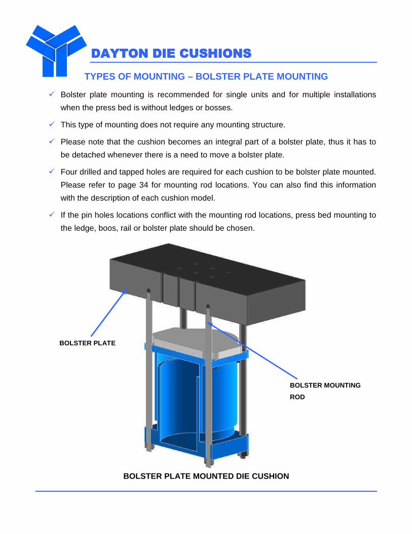
TYPES OF MOUNTING – BOLSTER PLATE MOUNTING
� Bolster plate mounting is recommended for single units and for multiple installations
when the press bed is without ledges or bosses.
� This type of mounting does not require any mounting structure.
� Please note that the cushion becomes an integral part of a bolster plate, thus it has to
be detached whenever there is a need to move a bolster plate.
� Four drilled and tapped holes are required for each cushion to be bolster plate mounted.
Please refer to page 34 for mounting rod locations. You can also find this information
with the description of each cushion model.
� If the pin holes locations conflict with the mounting rod locations, press bed mounting to
the ledge, boos, rail or bolster plate should be chosen.
BOLSTER PLATE MOUNTED DIE CUSHION
BOLSTER PLATE
BOLSTER MOUNTING
ROD
DAYTON DIE CUSHIONSDAYTON DIE CUSHIONSDAYTON DIE CUSHIONSDAYTON DIE CUSHIONS
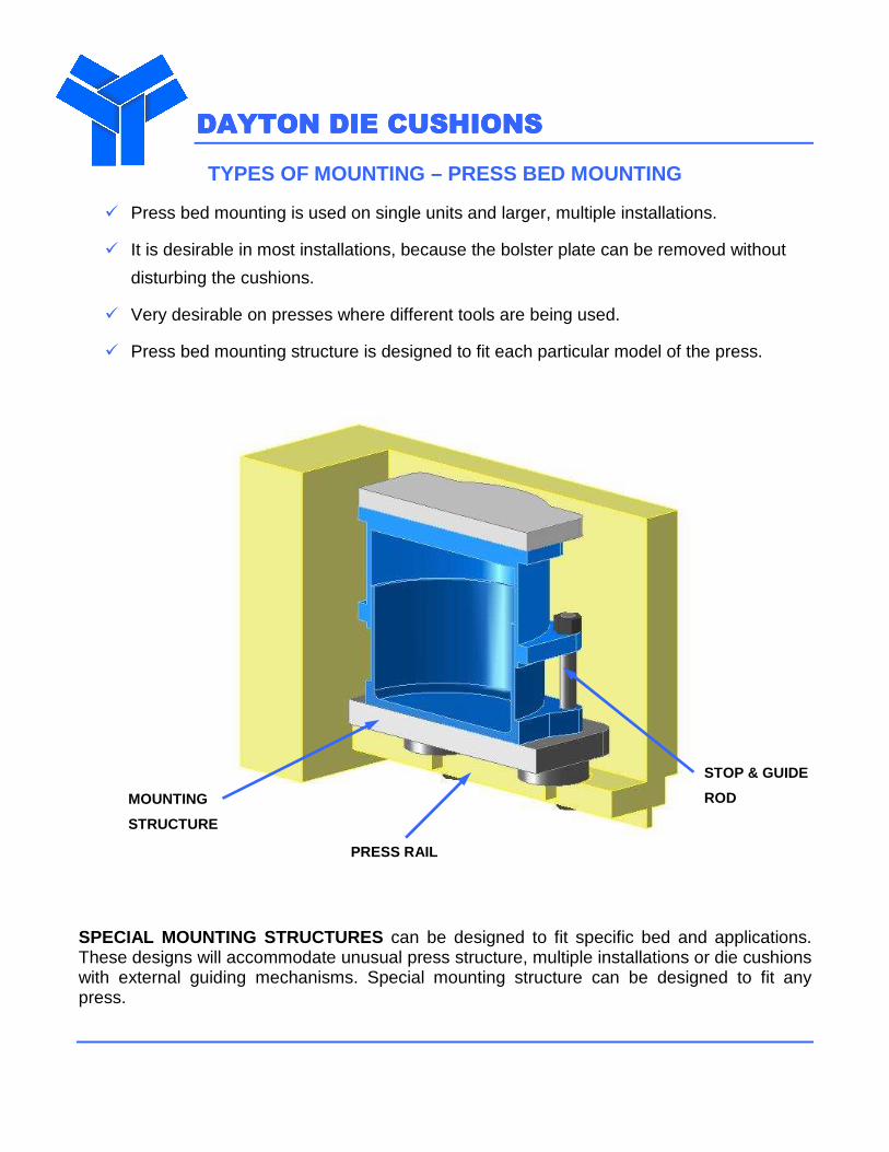
TYPES OF MOUNTING – PRESS BED MOUNTING
� Press bed mounting is used on single units and larger, multiple installations.
� It is desirable in most installations, because the bolster plate can be removed without
disturbing the cushions.
� Very desirable on presses where different tools are being used.
� Press bed mounting structure is designed to fit each particular model of the press.
SPECIAL MOUNTING STRUCTURES can be designed to fit specific bed and applications. These designs will accommodate unusual press structure, multiple installations or die cushions with external guiding mechanisms. Special mounting structure can be designed to fit any press.
MOUNTING
STRUCTURE
STOP & GUIDE
ROD
PRESS RAIL
DAYTON DIE CUSHIONSDAYTON DIE CUSHIONSDAYTON DIE CUSHIONSDAYTON DIE CUSHIONS
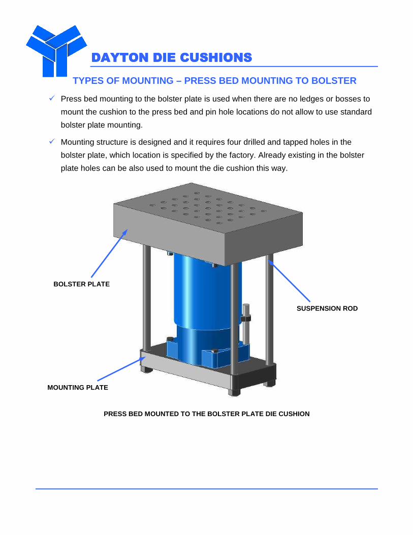
TYPES OF MOUNTING – PRESS BED MOUNTING TO BOL STER
� Press bed mounting to the bolster plate is used when there are no ledges or bosses to
mount the cushion to the press bed and pin hole locations do not allow to use standard
bolster plate mounting.
� Mounting structure is designed and it requires four drilled and tapped holes in the
bolster plate, which location is specified by the factory. Already existing in the bolster
plate holes can be also used to mount the die cushion this way.
PRESS BED MOUNTED TO THE BOLSTER PLATE DIE CUSHION
BOLSTER PLATE
MOUNTING PLATE
SUSPENSION ROD
DAYTON DIE CUSHIONSDAYTON DIE CUSHIONSDAYTON DIE CUSHIONSDAYTON DIE CUSHIONS
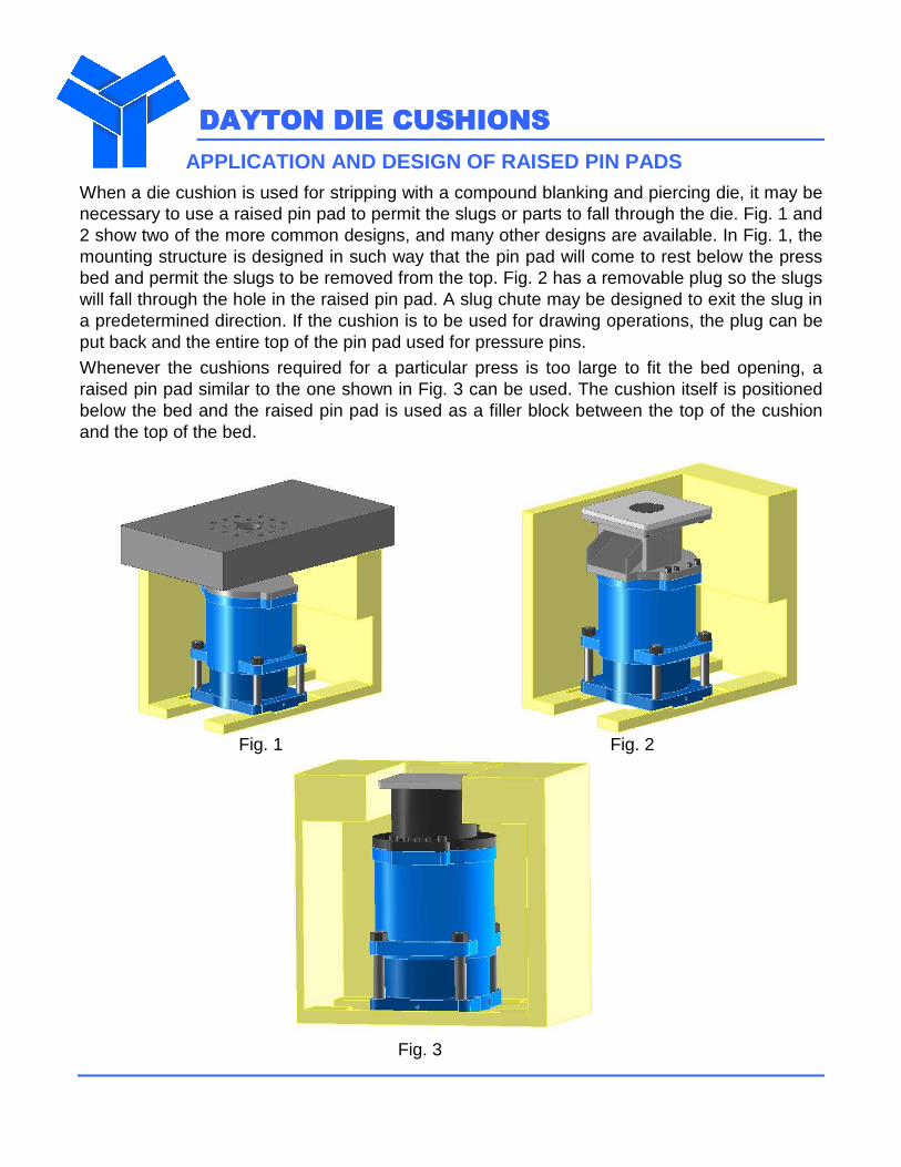
APPLICATION AND DESIGN OF RAISED PIN PADS When a die cushion is used for stripping with a compound blanking and piercing die, it may be necessary to use a raised pin pad to permit the slugs or parts to fall through the die. Fig. 1 and 2 show two of the more common designs, and many other designs are available. In Fig. 1, the mounting structure is designed in such way that the pin pad will come to rest below the press bed and permit the slugs to be removed from the top. Fig. 2 has a removable plug so the slugs will fall through the hole in the raised pin pad. A slug chute may be designed to exit the slug in a predetermined direction. If the cushion is to be used for drawing operations, the plug can be put back and the entire top of the pin pad used for pressure pins.
Whenever the cushions required for a particular press is too large to fit the bed opening, a raised pin pad similar to the one shown in Fig. 3 can be used. The cushion itself is positioned below the bed and the raised pin pad is used as a filler block between the top of the cushion and the top of the bed.
Fig. 1 Fig. 2 Fig. 3
DAYTON DIE CUSHIONSDAYTON DIE CUSHIONSDAYTON DIE CUSHIONSDAYTON DIE CUSHIONS
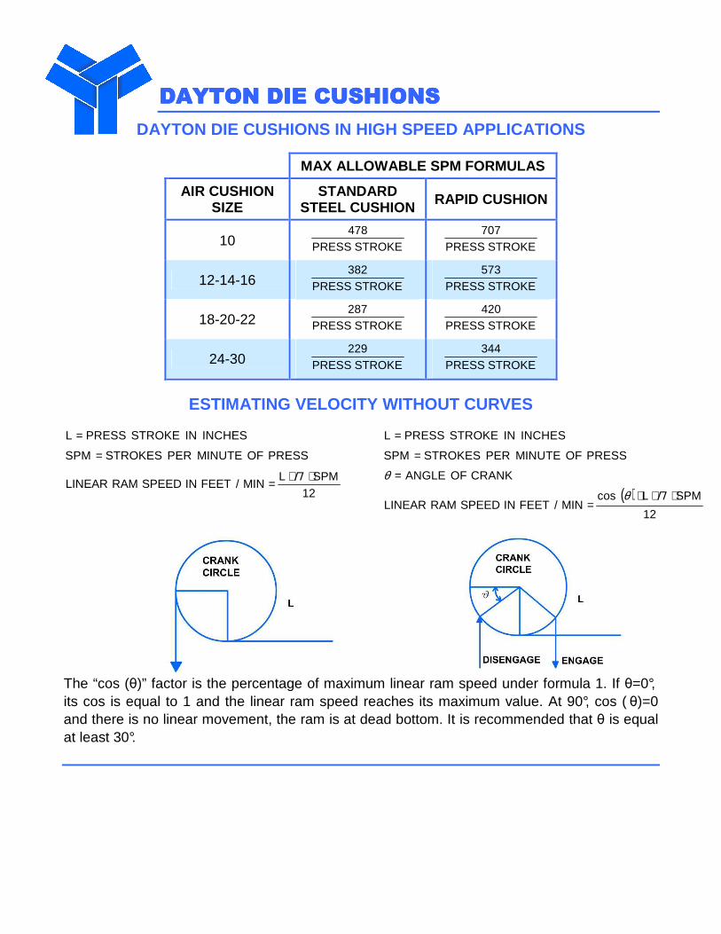
DAYTON DIE CUSHIONS IN HIGH SPEED APPLICATIONS
MAX ALLOWABLE SPM FORMULAS
AIR CUSHION SIZE
STANDARD STEEL CUSHION RAPID CUSHION
10 STROKEPRESS478
STROKEPRESS707
12-14-16 STROKEPRESS382
STROKEPRESS573
18-20-22 STROKEPRESS287
STROKEPRESS420
24-30 STROKEPRESS229
STROKEPRESS344
ESTIMATING VELOCITY WITHOUT CURVES
INCHESINSTROKEPRESSL =
PRESSOFMINUTEPERSTROKESSPM =
12SPML
MIN/FEETINSPEEDRAMLINEAR⋅⋅= Π
INCHESINSTROKEPRESSL = PRESSOFMINUTEPERSTROKESSPM =
CRANKOFANGLE=θ ( )
12
SPMLcosMIN/FEETINSPEEDRAMLINEAR
⋅⋅⋅=
Πθ
The “cos (θ)” factor is the percentage of maximum linear ram speed under formula 1. If θ=0°, its cos is equal to 1 and the linear ram speed reaches its maximum value. At 90°, cos ( θ)=0 and there is no linear movement, the ram is at dead bottom. It is recommended that θ is equal at least 30°.
DAYTON DIE CUSHIONSDAYTON DIE CUSHIONSDAYTON DIE CUSHIONSDAYTON DIE CUSHIONS
NEW DEVELOPMENTS JUST INTRODUCED!
Our ˝BULLDOG˝ line of cushions is a combination of air and hydraulic unit. These cushions
can achieve up to four times the tonnage in a given press bed area. They are designed for
cylinder diameters of 18” to 48”. In addition to reaching new tonnage standards, these
cushions also have:
� an automatic lubrication system - simplifying maintenance
� more robust off center loading - more die placement freedom
� an automatic “block up” feature - not letting the pins down at night
� a decelerator - ram speeds up to 150 feet per minute
� an internal hydraulic stroke adjustment - like our famous “D” line
The units are all pre-machined to accept optional advanced hydraulic valving that can easily be
tied into your press electronics. This provides you with a numerically controlled (NC) cushion
coupled with a hydraulic hold-down. This option is often requested for larger presses; in
particular, transfer type presses or robotically loaded presses. Die setups and work piece
removal are being driven even faster. These new cushion design advantages anticipate the
next ten years of press development! Don’t settle for less when making your next major press
investment!

DDDDAYTON DIE CUSHIONSAYTON DIE CUSHIONSAYTON DIE CUSHIONSAYTON DIE CUSHIONS
CHOOSING BETWEEN AIR AND NITROGEN??
ADVANTAGES OF AIR:
� Less Die Space = Less Die Materials Cost = Less Workpiece Cost
� Less Die Pocketing = Less Machining = Less Diemaker’s Time
� Less Gas Costs = Less Shop Space = Less Running Cost
� No Exotic Gases = No Vendor Waiting = No Recharging Cost
� Simple Steel Pins = Simple Maintenance = Simple Changes
� 1/10th the Pressure = 1/10th the Seal Failure = 1/10th the Repairs
� Small Open Height = Small Press = Small Scheduling Problem
� Easily Adjustable Pressure = Easily Adjustable Holding Force
� Easy Stroke Changes = Easy Pin Changes = Easy Setup Changes
� No “Try and See”, “Hope it Works” = 70 Year MFG. and Installation History!
No Unknown Life Cycle - Many Customers Run 40+ years, no problem
One Time Installation - Not Redone For Every Die
Shop Floor Job Setup at $15/HR - Not Toolroom Setup at $65/HR
Can Easily Accept Workpiece Material Variations
MAKE YOUR DECISION FOR A DAYTON AIR CUSHION!!
DAYTON DIE DAYTON DIE DAYTON DIE DAYTON DIE CUSHIONSCUSHIONSCUSHIONSCUSHIONS
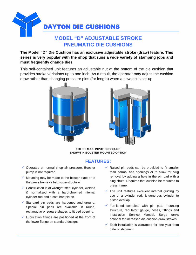
MODEL “D” ADJUSTABLE STROKE PNEUMATIC DIE CUSHIONS
The Model “D” Die Cushion has an exclusive adjustab le stroke (draw) feature. This series is very popular with the shop that runs a wi de variety of stamping jobs and must frequently change dies.
This self-contained unit features an adjustable nut at the bottom of the die cushion that provides stroke variations up to one inch. As a result, the operator may adjust the cushion draw rather than changing pressure pins (for length) when a new job is set-up.
100 PSI MAX. INPUT PRESSURE SHOWN IN BOLSTER MOUNTED OPTION
FEATURES: � Operates at normal shop air pressure. Booster
pump is not required.
� Mounting may be made to the bolster plate or to the press frame or bed superstructure.
� Construction is of wrought steel cylinder, welded & normalized with a hard-chromed internal cylinder rod and a cast iron piston.
� Standard pin pads are hardened and ground. Special pin pads are available in round, rectangular or square shapes to fit bed opening.
� Lubrication fittings are positioned at the front of the lower flange on standard designs.
� Raised pin pads can be provided to fit smaller than normal bed openings or to allow for slug removal by adding a hole in the pin pad with a slug chute. Requires that cushion be mounted to press frame.
� The unit features excellent internal guiding by use of a cylinder rod, & generous cylinder to piston overlap.
� Furnished complete with pin pad, mounting structure, regulator, gauge, hoses, fittings and Installation Service Manual. Surge tanks optional for increased die cushion draw strokes.
� Each installation is warranted for one year from date of shipment.

DAYTON DIE CUSHIONSDAYTON DIE CUSHIONSDAYTON DIE CUSHIONSDAYTON DIE CUSHIONS
CUSHION SELECTION CHART
STANDARD PIN PADS CUSHION DRAW MODEL
TONS@ 100
P.S.I. L-R F-B CIR.
HEIGHT STD.
DRAW STD** MAX
MAX ADJ.
OPER. HEIGHT STD. DRAW
D-5 0.9 6-5/8 3 5-3/4 12-3/16 1-1/4 2-11/16 5/8 13-7/16
D-6 1.4 8-1/2 3-1/8 7 14-1/8 1-3/4 3-1/4 5/8 15-7/8
D-8 2.5 10 4-1/2 9 17-9/16 2 3-3/4 5/8 19-9/16
D-10 3.9 12-3/8 5-1/8 11 18-1/16 2 3-3/4 5/8 20-1/16
D-12 5.7 13-1/2 7 13-1/8 19-1/2 2 3-3/4 1/2 21-1/2
D-14 7.7 16-1/4 8-3/4 15-1/4 22-3/8 2-1/2 4-3/4 1/2 24-8/7
D-16 10 19 9 17-1/4 21-15/16 2-1/2 5-3/4 1 24-7/16
*Height for standard draw only and does not include pin pad nor mounting structure thickness. ** For stokes longer than standard, use surge tank.
MOUNTING ROD SPECIFICATIONS FOR STANDARD BOLSTER MO UNTED DIE CUSHIONS
Model L-R F-B H Thread
D-5 5-3/4 3-7/8 3/4 3/8 -16
D-6 7-1/4 4 3/4 1/2 -13
D-8 8-19/32 5-19/32 1 5/8 -11
D-10 10-7/8 6-3/8 1 3/4 -10
D-12 12 8-7/16 1-1/4 7/8 -9
D-14 14-1/4 10-1/4 1-3/8 1 -8
D-16 16-1/2 11 1-5/8 1-1/4 -7
DRILL/TAP FOUR HOLES
IN BOLSTER PLATE TO ACCEPT THREAD/HEIGHT
DAYTON DIE CUSHIONSDAYTON DIE CUSHIONSDAYTON DIE CUSHIONSDAYTON DIE CUSHIONS
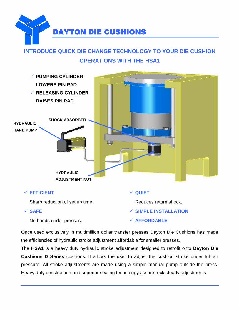
INTRODUCE QUICK DIE CHANGE TECHNOLOGY TO YOUR DIE C USHION
OPERATIONS WITH THE HSA1
� EFFICIENT
Sharp reduction of set up time.
� SAFE
No hands under presses.
� QUIET
Reduces return shock.
� SIMPLE INSTALLATION
� AFFORDABLE
Once used exclusively in multimillion dollar transfer presses Dayton Die Cushions has made
the efficiencies of hydraulic stroke adjustment affordable for smaller presses.
The HSA1 is a heavy duty hydraulic stroke adjustment designed to retrofit onto Dayton Die
Cushions D Series cushions. It allows the user to adjust the cushion stroke under full air
pressure. All stroke adjustments are made using a simple manual pump outside the press.
Heavy duty construction and superior sealing technology assure rock steady adjustments.
SHOCK ABSORBER HYDRAULIC
HAND PUMP
HYDRAULIC
ADJUSTMENT NUT
� PUMPING CYLINDER
LOWERS PIN PAD
� RELEASING CYLINDER
RAISES PIN PAD
DAYTON DIE CUSHIONSDAYTON DIE CUSHIONSDAYTON DIE CUSHIONSDAYTON DIE CUSHIONS
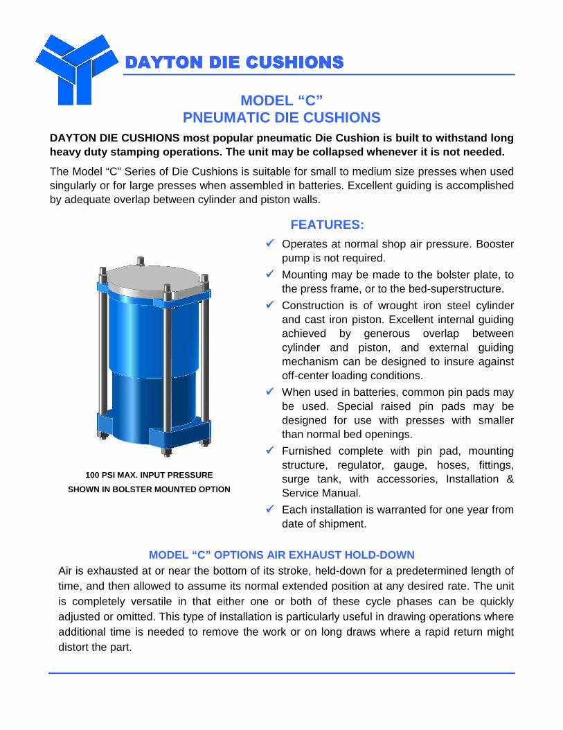
MODEL “C” PNEUMATIC DIE CUSHIONS
DAYTON DIE CUSHIONS most popular pneumatic Die Cush ion is built to withstand long heavy duty stamping operations. The unit may be col lapsed whenever it is not needed.
The Model “C” Series of Die Cushions is suitable for small to medium size presses when used singularly or for large presses when assembled in batteries. Excellent guiding is accomplished by adequate overlap between cylinder and piston walls.
100 PSI MAX. INPUT PRESSURE
SHOWN IN BOLSTER MOUNTED OPTION
FEATURES: ���� Operates at normal shop air pressure. Booster
pump is not required.
���� Mounting may be made to the bolster plate, to the press frame, or to the bed-superstructure.
���� Construction is of wrought iron steel cylinder and cast iron piston. Excellent internal guiding achieved by generous overlap between cylinder and piston, and external guiding mechanism can be designed to insure against off-center loading conditions.
���� When used in batteries, common pin pads may be used. Special raised pin pads may be designed for use with presses with smaller than normal bed openings.
���� Furnished complete with pin pad, mounting structure, regulator, gauge, hoses, fittings, surge tank, with accessories, Installation & Service Manual.
���� Each installation is warranted for one year from date of shipment.
MODEL “C” OPTIONS AIR EXHAUST HOLD-DOWN
Air is exhausted at or near the bottom of its stroke, held-down for a predetermined length of time, and then allowed to assume its normal extended position at any desired rate. The unit is completely versatile in that either one or both of these cycle phases can be quickly adjusted or omitted. This type of installation is particularly useful in drawing operations where additional time is needed to remove the work or on long draws where a rapid return might distort the part.
DAYTON DIE CUSHIONSDAYTON DIE CUSHIONSDAYTON DIE CUSHIONSDAYTON DIE CUSHIONS
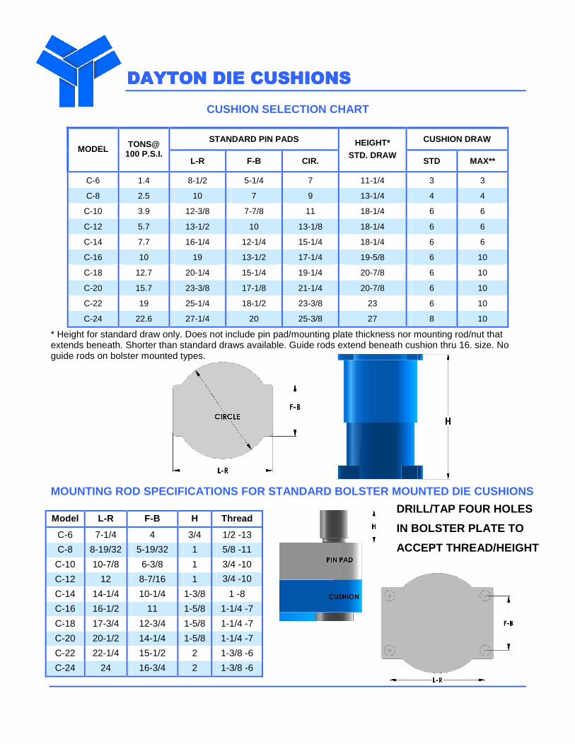
CUSHION SELECTION CHART
STANDARD PIN PADS CUSHION DRAW MODEL TONS@
100 P.S.I. L-R F-B CIR.
HEIGHT* STD. DRAW
STD MAX**
C-6 1.4 8-1/2 5-1/4 7 11-1/4 3 3
C-8 2.5 10 7 9 13-1/4 4 4
C-10 3.9 12-3/8 7-7/8 11 18-1/4 6 6
C-12 5.7 13-1/2 10 13-1/8 18-1/4 6 6
C-14 7.7 16-1/4 12-1/4 15-1/4 18-1/4 6 6
C-16 10 19 13-1/2 17-1/4 19-5/8 6 10
C-18 12.7 20-1/4 15-1/4 19-1/4 20-7/8 6 10
C-20 15.7 23-3/8 17-1/8 21-1/4 20-7/8 6 10
C-22 19 25-1/4 18-1/2 23-3/8 23 6 10
C-24 22.6 27-1/4 20 25-3/8 27 8 10
* Height for standard draw only. Does not include pin pad/mounting plate thickness nor mounting rod/nut that extends beneath. Shorter than standard draws available. Guide rods extend beneath cushion thru 16. size. No guide rods on bolster mounted types.
MOUNTING ROD SPECIFICATIONS FOR STANDARD BOLSTER MO UNTED DIE CUSHIONS
Model L-R F-B H Thread
C-6 7-1/4 4 3/4 1/2 -13
C-8 8-19/32 5-19/32 1 5/8 -11
C-10 10-7/8 6-3/8 1 3/4 -10
C-12 12 8-7/16 1 3/4 -10
C-14 14-1/4 10-1/4 1-3/8 1 -8
C-16 16-1/2 11 1-5/8 1-1/4 -7
C-18 17-3/4 12-3/4 1-5/8 1-1/4 -7
C-20 20-1/2 14-1/4 1-5/8 1-1/4 -7
C-22 22-1/4 15-1/2 2 1-3/8 -6
C-24 24 16-3/4 2 1-3/8 -6
DRILL/TAP FOUR HOLES
IN BOLSTER PLATE TO
ACCEPT THREAD/HEIGHT
DAYTON DIE CUSHIONSDAYTON DIE CUSHIONSDAYTON DIE CUSHIONSDAYTON DIE CUSHIONS
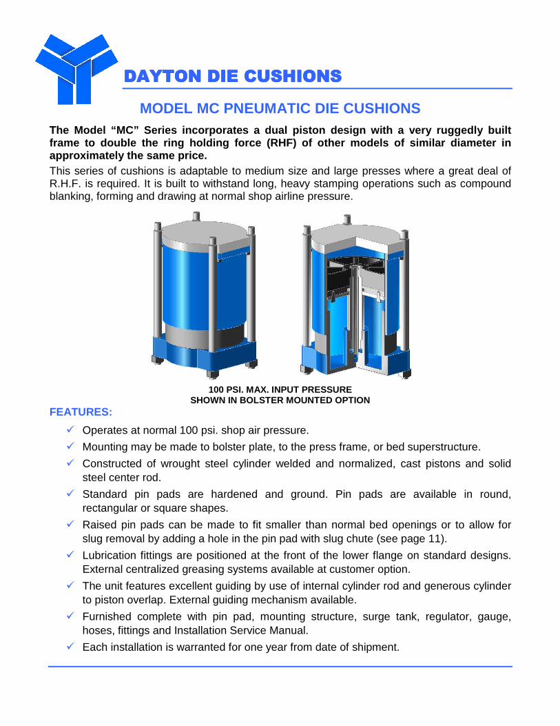
MODEL MC PNEUMATIC DIE CUSHIONS The Model “MC” Series incorporates a dual piston de sign with a very ruggedly built frame to double the ring holding force (RHF) of oth er models of similar diameter in approximately the same price. This series of cushions is adaptable to medium size and large presses where a great deal of R.H.F. is required. It is built to withstand long, heavy stamping operations such as compound blanking, forming and drawing at normal shop airline pressure.
100 PSI. MAX. INPUT PRESSURE SHOWN IN BOLSTER MOUNTED OPTION
FEATURES:
� Operates at normal 100 psi. shop air pressure.
� Mounting may be made to bolster plate, to the press frame, or bed superstructure.
� Constructed of wrought steel cylinder welded and normalized, cast pistons and solid steel center rod.
� Standard pin pads are hardened and ground. Pin pads are available in round, rectangular or square shapes.
� Raised pin pads can be made to fit smaller than normal bed openings or to allow for slug removal by adding a hole in the pin pad with slug chute (see page 11).
� Lubrication fittings are positioned at the front of the lower flange on standard designs. External centralized greasing systems available at customer option.
� The unit features excellent guiding by use of internal cylinder rod and generous cylinder to piston overlap. External guiding mechanism available.
� Furnished complete with pin pad, mounting structure, surge tank, regulator, gauge, hoses, fittings and Installation Service Manual.
� Each installation is warranted for one year from date of shipment.
DAYTON DIE CUSHIONSDAYTON DIE CUSHIONSDAYTON DIE CUSHIONSDAYTON DIE CUSHIONS
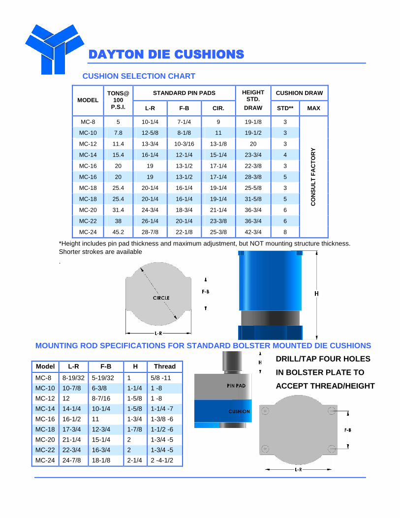
CUSHION SELECTION CHART
STANDARD PIN PADS CUSHION DRAW MODEL
TONS@ 100
P.S.I. L-R F-B CIR.
HEIGHT STD.
DRAW STD** MAX
MC-8 5 10-1/4 7-1/4 9 19-1/8 3
MC-10 7.8 12-5/8 8-1/8 11 19-1/2 3
MC-12 11.4 13-3/4 10-3/16 13-1/8 20 3
MC-14 15.4 16-1/4 12-1/4 15-1/4 23-3/4 4
MC-16 20 19 13-1/2 17-1/4 22-3/8 3
MC-16 20 19 13-1/2 17-1/4 28-3/8 5
MC-18 25.4 20-1/4 16-1/4 19-1/4 25-5/8 3
MC-18 25.4 20-1/4 16-1/4 19-1/4 31-5/8 5
MC-20 31.4 24-3/4 18-3/4 21-1/4 36-3/4 6
MC-22 38 26-1/4 20-1/4 23-3/8 36-3/4 6
MC-24 45.2 28-7/8 22-1/8 25-3/8 42-3/4 8
CO
NS
ULT
FA
CT
OR
Y
*Height includes pin pad thickness and maximum adjustment, but NOT mounting structure thickness. Shorter strokes are available
. MOUNTING ROD SPECIFICATIONS FOR STANDARD BOLSTER MO UNTED DIE CUSHIONS
Model L-R F-B H Thread
MC-8 8-19/32 5-19/32 1 5/8 -11
MC-10 10-7/8 6-3/8 1-1/4 1 -8
MC-12 12 8-7/16 1-5/8 1 -8
MC-14 14-1/4 10-1/4 1-5/8 1-1/4 -7
MC-16 16-1/2 11 1-3/4 1-3/8 -6
MC-18 17-3/4 12-3/4 1-7/8 1-1/2 -6
MC-20 21-1/4 15-1/4 2 1-3/4 -5
MC-22 22-3/4 16-3/4 2 1-3/4 -5
MC-24 24-7/8 18-1/8 2-1/4 2 -4-1/2
DRILL/TAP FOUR HOLES
IN BOLSTER PLATE TO
ACCEPT THREAD/HEIGHT
DAYTON DIE CUSHIONSDAYTON DIE CUSHIONSDAYTON DIE CUSHIONSDAYTON DIE CUSHIONS
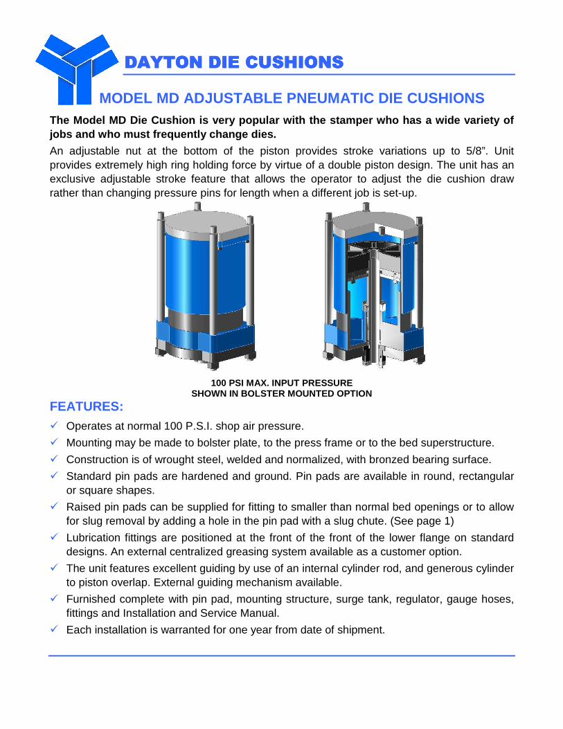
MODEL MD ADJUSTABLE PNEUMATIC DIE CUSHIONS The Model MD Die Cushion is very popular with the s tamper who has a wide variety of jobs and who must frequently change dies.
An adjustable nut at the bottom of the piston provides stroke variations up to 5/8”. Unit provides extremely high ring holding force by virtue of a double piston design. The unit has an exclusive adjustable stroke feature that allows the operator to adjust the die cushion draw rather than changing pressure pins for length when a different job is set-up.
100 PSI MAX. INPUT PRESSURE SHOWN IN BOLSTER MOUNTED OPTION
FEATURES: � Operates at normal 100 P.S.I. shop air pressure.
� Mounting may be made to bolster plate, to the press frame or to the bed superstructure.
� Construction is of wrought steel, welded and normalized, with bronzed bearing surface.
� Standard pin pads are hardened and ground. Pin pads are available in round, rectangular or square shapes.
� Raised pin pads can be supplied for fitting to smaller than normal bed openings or to allow for slug removal by adding a hole in the pin pad with a slug chute. (See page 1)
� Lubrication fittings are positioned at the front of the front of the lower flange on standard designs. An external centralized greasing system available as a customer option.
� The unit features excellent guiding by use of an internal cylinder rod, and generous cylinder to piston overlap. External guiding mechanism available.
� Furnished complete with pin pad, mounting structure, surge tank, regulator, gauge hoses, fittings and Installation and Service Manual.
� Each installation is warranted for one year from date of shipment.
DAYTON DIE CUSHIONSDAYTON DIE CUSHIONSDAYTON DIE CUSHIONSDAYTON DIE CUSHIONS
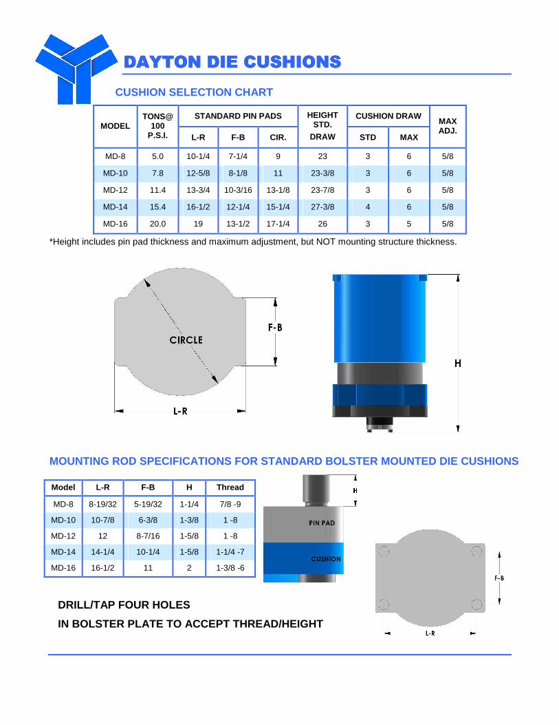
CUSHION SELECTION CHART
STANDARD PIN PADS CUSHION DRAW MODEL
TONS@ 100
P.S.I. L-R F-B CIR.
HEIGHT STD.
DRAW STD MAX
MAX ADJ.
MD-8 5.0 10-1/4 7-1/4 9 23 3 6 5/8
MD-10 7.8 12-5/8 8-1/8 11 23-3/8 3 6 5/8
MD-12 11.4 13-3/4 10-3/16 13-1/8 23-7/8 3 6 5/8
MD-14 15.4 16-1/2 12-1/4 15-1/4 27-3/8 4 6 5/8
MD-16 20.0 19 13-1/2 17-1/4 26 3 5 5/8
*Height includes pin pad thickness and maximum adjustment, but NOT mounting structure thickness.
MOUNTING ROD SPECIFICATIONS FOR STANDARD BOLSTER MO UNTED DIE CUSHIONS
Model L-R F-B H Thread
MD-8 8-19/32 5-19/32 1-1/4 7/8 -9
MD-10 10-7/8 6-3/8 1-3/8 1 -8
MD-12 12 8-7/16 1-5/8 1 -8
MD-14 14-1/4 10-1/4 1-5/8 1-1/4 -7
MD-16 16-1/2 11 2 1-3/8 -6
DRILL/TAP FOUR HOLES
IN BOLSTER PLATE TO ACCEPT THREAD/HEIGHT
DAYTON DIE CUSHIONSDAYTON DIE CUSHIONSDAYTON DIE CUSHIONSDAYTON DIE CUSHIONS
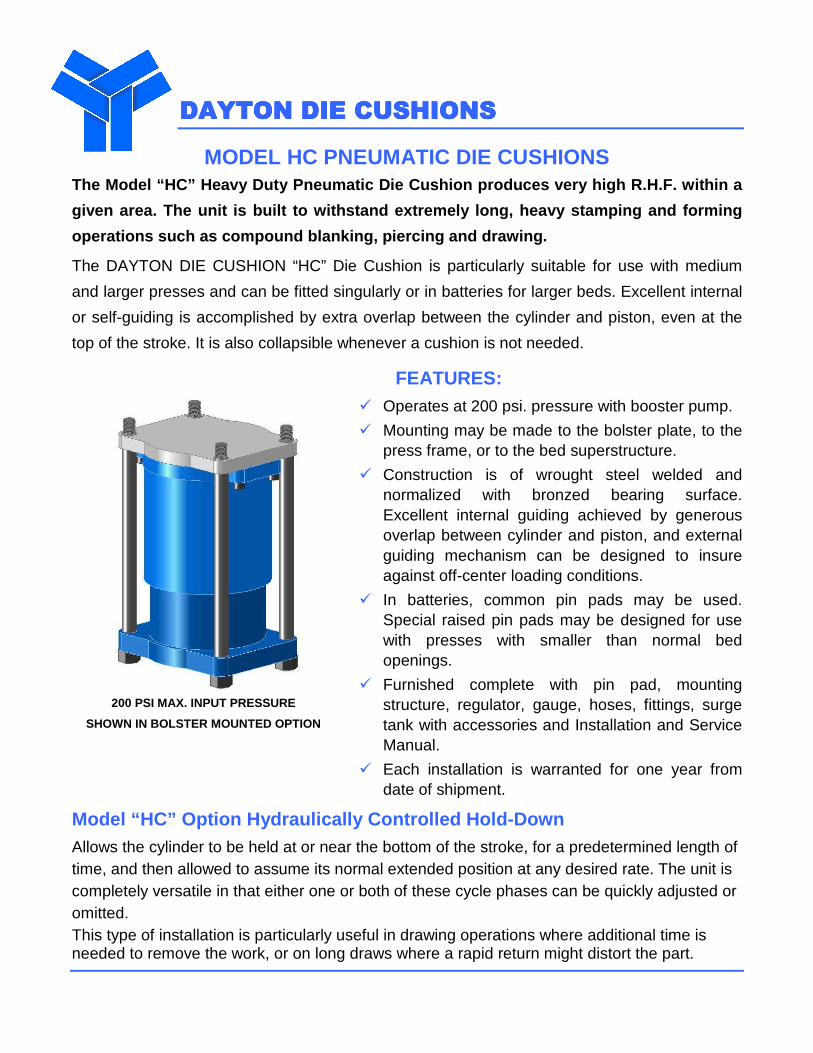
MODEL HC PNEUMATIC DIE CUSHIONS The Model “HC” Heavy Duty Pneumatic Die Cushion pro duces very high R.H.F. within a
given area. The unit is built to withstand extremel y long, heavy stamping and forming
operations such as compound blanking, piercing and drawing.
The DAYTON DIE CUSHION “HC” Die Cushion is particularly suitable for use with medium
and larger presses and can be fitted singularly or in batteries for larger beds. Excellent internal
or self-guiding is accomplished by extra overlap between the cylinder and piston, even at the
top of the stroke. It is also collapsible whenever a cushion is not needed.
200 PSI MAX. INPUT PRESSURE
SHOWN IN BOLSTER MOUNTED OPTION
FEATURES: � Operates at 200 psi. pressure with booster pump.
� Mounting may be made to the bolster plate, to the press frame, or to the bed superstructure.
� Construction is of wrought steel welded and normalized with bronzed bearing surface. Excellent internal guiding achieved by generous overlap between cylinder and piston, and external guiding mechanism can be designed to insure against off-center loading conditions.
� In batteries, common pin pads may be used. Special raised pin pads may be designed for use with presses with smaller than normal bed openings.
� Furnished complete with pin pad, mounting structure, regulator, gauge, hoses, fittings, surge tank with accessories and Installation and Service Manual.
� Each installation is warranted for one year from date of shipment.
Model “HC” Option Hydraulically Controlled Hold-Dow n
Allows the cylinder to be held at or near the bottom of the stroke, for a predetermined length of time, and then allowed to assume its normal extended position at any desired rate. The unit is completely versatile in that either one or both of these cycle phases can be quickly adjusted or omitted. This type of installation is particularly useful in drawing operations where additional time is needed to remove the work, or on long draws where a rapid return might distort the part.
DAYTON DIE CUSHIONSDAYTON DIE CUSHIONSDAYTON DIE CUSHIONSDAYTON DIE CUSHIONS
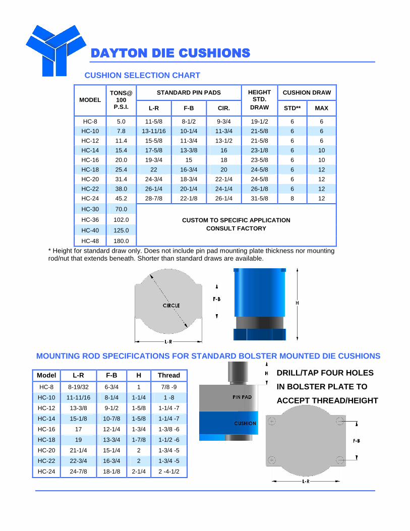
CUSHION SELECTION CHART
STANDARD PIN PADS CUSHION DRAW MODEL
TONS@ 100
P.S.I. L-R F-B CIR.
HEIGHT STD.
DRAW STD** MAX
HC-8 5.0 11-5/8 8-1/2 9-3/4 19-1/2 6 6
HC-10 7.8 13-11/16 10-1/4 11-3/4 21-5/8 6 6
HC-12 11.4 15-5/8 11-3/4 13-1/2 21-5/8 6 6
HC-14 15.4 17-5/8 13-3/8 16 23-1/8 6 10
HC-16 20.0 19-3/4 15 18 23-5/8 6 10
HC-18 25.4 22 16-3/4 20 24-5/8 6 12
HC-20 31.4 24-3/4 18-3/4 22-1/4 24-5/8 6 12
HC-22 38.0 26-1/4 20-1/4 24-1/4 26-1/8 6 12
HC-24 45.2 28-7/8 22-1/8 26-1/4 31-5/8 8 12
HC-30 70.0
HC-36 102.0
HC-40 125.0
HC-48 180.0
CUSTOM TO SPECIFIC APPLICATION CONSULT FACTORY
* Height for standard draw only. Does not include pin pad mounting plate thickness nor mounting rod/nut that extends beneath. Shorter than standard draws are available.
MOUNTING ROD SPECIFICATIONS FOR STANDARD BOLSTER MO UNTED DIE CUSHIONS
Model L-R F-B H Thread
HC-8 8-19/32 6-3/4 1 7/8 -9
HC-10 11-11/16 8-1/4 1-1/4 1 -8
HC-12 13-3/8 9-1/2 1-5/8 1-1/4 -7
HC-14 15-1/8 10-7/8 1-5/8 1-1/4 -7
HC-16 17 12-1/4 1-3/4 1-3/8 -6
HC-18 19 13-3/4 1-7/8 1-1/2 -6
HC-20 21-1/4 15-1/4 2 1-3/4 -5
HC-22 22-3/4 16-3/4 2 1-3/4 -5
HC-24 24-7/8 18-1/8 2-1/4 2 -4-1/2
DRILL/TAP FOUR HOLES
IN BOLSTER PLATE TO
ACCEPT THREAD/HEIGHT
DAYTON DIE CUSHIONSDAYTON DIE CUSHIONSDAYTON DIE CUSHIONSDAYTON DIE CUSHIONS
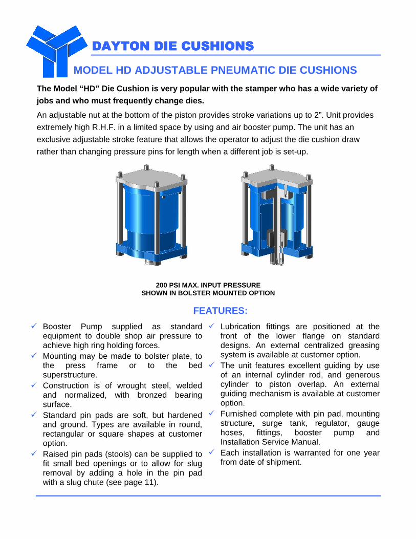
MODEL HD ADJUSTABLE PNEUMATIC DIE CUSHIONS
The Model “HD” Die Cushion is very popular with the stamper who has a wide variety of
jobs and who must frequently change dies.
An adjustable nut at the bottom of the piston provides stroke variations up to 2”. Unit provides
extremely high R.H.F. in a limited space by using and air booster pump. The unit has an
exclusive adjustable stroke feature that allows the operator to adjust the die cushion draw
rather than changing pressure pins for length when a different job is set-up.
200 PSI MAX. INPUT PRESSURE SHOWN IN BOLSTER MOUNTED OPTION
FEATURES:
� Booster Pump supplied as standard equipment to double shop air pressure to achieve high ring holding forces.
� Mounting may be made to bolster plate, to the press frame or to the bed superstructure.
� Construction is of wrought steel, welded and normalized, with bronzed bearing surface.
� Standard pin pads are soft, but hardened and ground. Types are available in round, rectangular or square shapes at customer option.
� Raised pin pads (stools) can be supplied to fit small bed openings or to allow for slug removal by adding a hole in the pin pad with a slug chute (see page 11).
� Lubrication fittings are positioned at the front of the lower flange on standard designs. An external centralized greasing system is available at customer option.
� The unit features excellent guiding by use of an internal cylinder rod, and generous cylinder to piston overlap. An external guiding mechanism is available at customer option.
� Furnished complete with pin pad, mounting structure, surge tank, regulator, gauge hoses, fittings, booster pump and Installation Service Manual.
� Each installation is warranted for one year from date of shipment.
DAYTON DIE CUSHIONSDAYTON DIE CUSHIONSDAYTON DIE CUSHIONSDAYTON DIE CUSHIONS
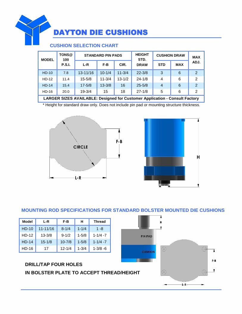
CUSHION SELECTION CHART
STANDARD PIN PADS CUSHION DRAW MODEL
TONS@ 100
P.S.I. L-R F-B CIR.
HEIGHT STD.
DRAW STD MAX
MAX ADJ.
HD-10 7.8 13-11/16 10-1/4 11-3/4 22-3/8 3 6 2
HD-12 11.4 15-5/8 11-3/4 13-1/2 24-1/8 4 6 2
HD-14 15.4 17-5/8 13-3/8 16 25-5/8 4 6 2
HD-16 20.0 19-3/4 15 18 27-1/8 5 6 2
LARGER SIZES AVAILABLE: Designed for Customer Appli cation - Consult Factory
* Height for standard draw only. Does not include pin pad or mounting structure thickness.
MOUNTING ROD SPECIFICATIONS FOR STANDARD BOLSTER MO UNTED DIE CUSHIONS
Model L-R F-B H Thread
HD-10 11-11/16 8-1/4 1-1/4 1 -8
HD-12 13-3/8 9-1/2 1-5/8 1-1/4 -7
HD-14 15-1/8 10-7/8 1-5/8 1-1/4 -7
HD-16 17 12-1/4 1-3/4 1-3/8 -6
DRILL/TAP FOUR HOLES
IN BOLSTER PLATE TO ACCEPT THREAD/HEIGHT
DAYTON DIE CUSHIONSDAYTON DIE CUSHIONSDAYTON DIE CUSHIONSDAYTON DIE CUSHIONS
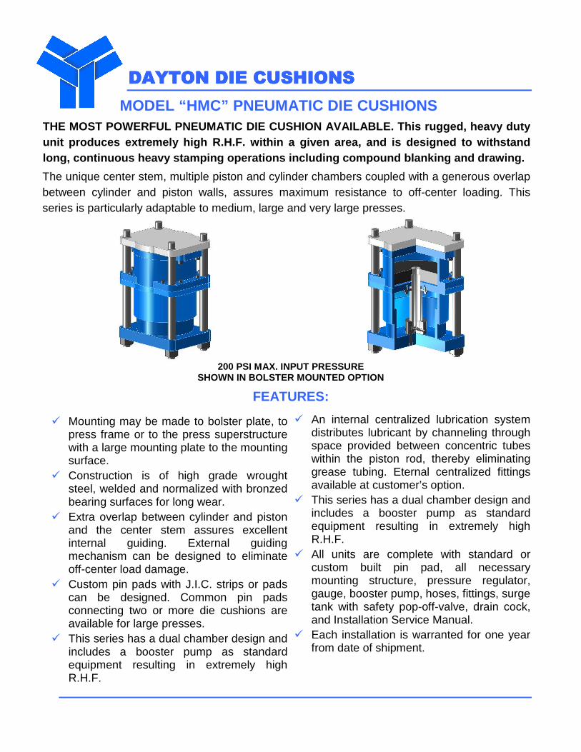
MODEL “HMC” PNEUMATIC DIE CUSHIONS THE MOST POWERFUL PNEUMATIC DIE CUSHION AVAILABLE. This rugged, heavy duty unit produces extremely high R.H.F. within a given area, and is designed to withstand long, continuous heavy stamping operations includin g compound blanking and drawing.
The unique center stem, multiple piston and cylinder chambers coupled with a generous overlap between cylinder and piston walls, assures maximum resistance to off-center loading. This series is particularly adaptable to medium, large and very large presses.
200 PSI MAX. INPUT PRESSURE
SHOWN IN BOLSTER MOUNTED OPTION
FEATURES:
� Mounting may be made to bolster plate, to press frame or to the press superstructure with a large mounting plate to the mounting surface.
� Construction is of high grade wrought steel, welded and normalized with bronzed bearing surfaces for long wear.
� Extra overlap between cylinder and piston and the center stem assures excellent internal guiding. External guiding mechanism can be designed to eliminate off-center load damage.
� Custom pin pads with J.I.C. strips or pads can be designed. Common pin pads connecting two or more die cushions are available for large presses.
� This series has a dual chamber design and includes a booster pump as standard equipment resulting in extremely high R.H.F.
� An internal centralized lubrication system distributes lubricant by channeling through space provided between concentric tubes within the piston rod, thereby eliminating grease tubing. Eternal centralized fittings available at customer’s option.
� This series has a dual chamber design and includes a booster pump as standard equipment resulting in extremely high R.H.F.
� All units are complete with standard or custom built pin pad, all necessary mounting structure, pressure regulator, gauge, booster pump, hoses, fittings, surge tank with safety pop-off-valve, drain cock, and Installation Service Manual.
� Each installation is warranted for one year from date of shipment.
DAYTON DIE CUSHIONSDAYTON DIE CUSHIONSDAYTON DIE CUSHIONSDAYTON DIE CUSHIONS
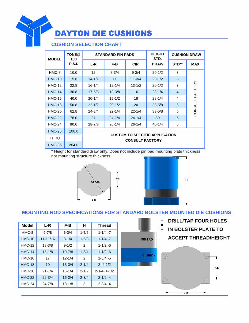
CUSHION SELECTION CHART
STANDARD PIN PADS CUSHION DRAW MODEL
TONS@ 100
P.S.I. L-R F-B CIR.
HEIGHT STD.
DRAW STD** MAX
HMC-8 10.0 12 8-3/4 9-3/4 20-1/2 3
HMC-10 15.6 14-1/2 11 11-3/4 20-1/2 3
HMC-12 22.8 16-1/4 12-1/4 13-1/2 20-1/2 3
HMC-14 30.8 17-5/8 13-3/8 16 28-1/4 4
HMC-16 40.0 20-1/4 15-1/2 18 28-1/4 4
HMC-18 50.8 22-1/2 20-1/2 20 33-5/8 5
HMC-20 62.8 24-3/4 22-1/4 22-1/4 33-5/8 5
HMC-22 76.0 27 24-1/4 24-1/4 39 6
HMC-24 90.0 28-7/8 26-1/4 26-1/4 40-1/4 6
CO
NS
ULT
FA
CT
OR
Y
HMC-26 106.0
THRU
HMC-36 204.0
CUSTOM TO SPECIFIC APPLICATION
CONSULT FACTORY
* Height for standard draw only. Does not include pin pad mounting plate thickness nor mounting structure thickness.
MOUNTING ROD SPECIFICATIONS FOR STANDARD BOLSTER MO UNTED DIE CUSHIONS
Model L-R F-B H Thread
HMC-8 9-7/8 6-3/4 1-5/8 1-1/4 -7
HMC-10 11-11/16 8-1/4 1-5/8 1-1/4 -7
HMC-12 13-3/8 9-1/2 2 1-1/2 -6
HMC-14 15-1/8 10-7/8 1-3/4 1-1/2 -6
HMC-16 17 12-1/4 2 1-3/4 -5
HMC-18 19 13-3/4 2-1/4 2 -4-1/2
HMC-20 21-1/4 15-1/4 2-1/2 2-1/4- 4-1/2
HMC-22 22-3/4 16-3/4 2-3/4 2-1/2 -4
HMC-24 24-7/8 18-1/8 3 2-3/4 -4
DRILL/TAP FOUR HOLES
IN BOLSTER PLATE TO
ACCEPT THREAD/HEIGHT
DAYTON DIE CUSHIONSDAYTON DIE CUSHIONSDAYTON DIE CUSHIONSDAYTON DIE CUSHIONS
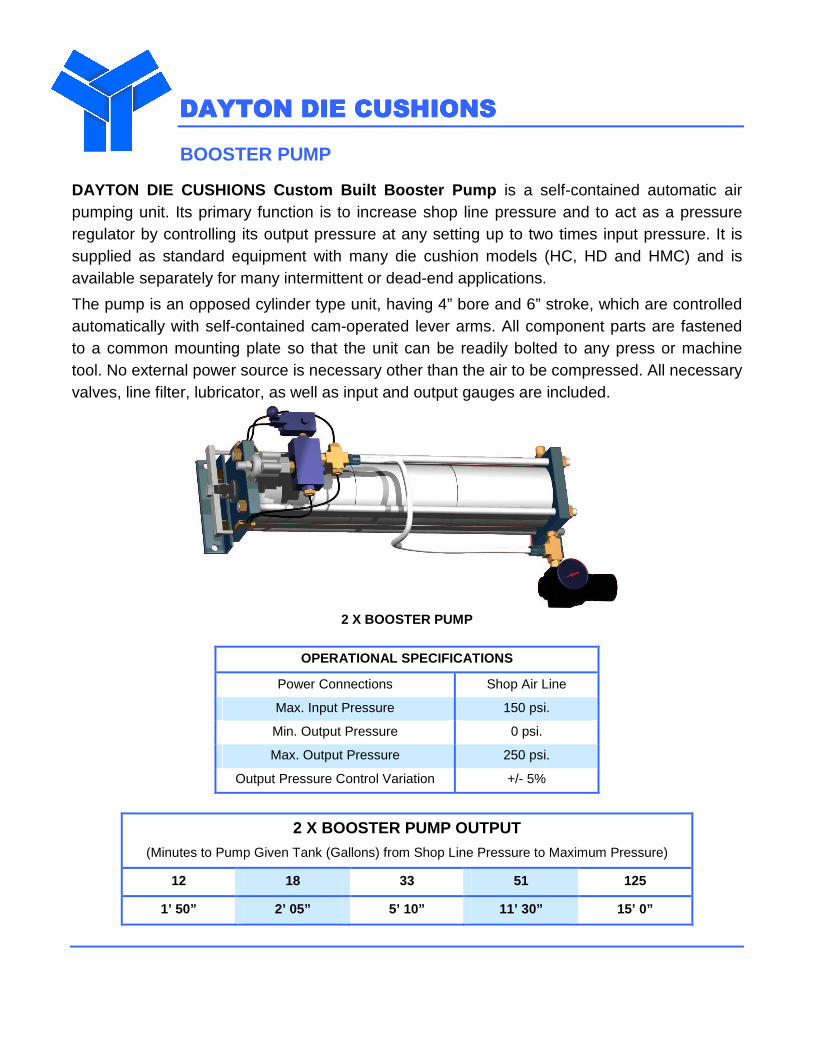
BOOSTER PUMP
DAYTON DIE CUSHIONS Custom Built Booster Pump is a self-contained automatic air pumping unit. Its primary function is to increase shop line pressure and to act as a pressure regulator by controlling its output pressure at any setting up to two times input pressure. It is supplied as standard equipment with many die cushion models (HC, HD and HMC) and is available separately for many intermittent or dead-end applications.
The pump is an opposed cylinder type unit, having 4” bore and 6” stroke, which are controlled automatically with self-contained cam-operated lever arms. All component parts are fastened to a common mounting plate so that the unit can be readily bolted to any press or machine tool. No external power source is necessary other than the air to be compressed. All necessary valves, line filter, lubricator, as well as input and output gauges are included.
2 X BOOSTER PUMP
OPERATIONAL SPECIFICATIONS
Power Connections Shop Air Line
Max. Input Pressure 150 psi.
Min. Output Pressure 0 psi.
Max. Output Pressure 250 psi.
Output Pressure Control Variation +/- 5%
2 X BOOSTER PUMP OUTPUT (Minutes to Pump Given Tank (Gallons) from Shop Line Pressure to Maximum Pressure)
12 18 33 51 125
1’ 50” 2’ 05” 5’ 10” 11’ 30” 15’ 0”
DADADADAYTON DIE CUSHIONSYTON DIE CUSHIONSYTON DIE CUSHIONSYTON DIE CUSHIONS
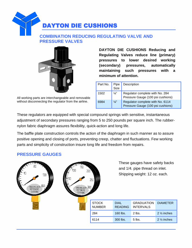
COMBINATION REDUCING REGULATING VALVE AND PRESSURE VALVES
DAYTON DIE CUSHIONS Reducing and Regulating Valves reduce line (primary) pressures to lower desired working (secondary) pressures, automatically maintaining such pressures with a minimum of attention.
All working parts are interchangeable and removable without disconnecting the regulator from the airline.
Part No. Pipe Size
Description
1502 ¼” Regulator complete with No. 284 Pressure Gauge (100 psi cushions)
6984 ¼” Regulator complete with No. 6114 Pressure Gauge (100 psi cushions)
These regulators are equipped with special compound springs with sensitive, instantaneous
adjustment of secondary pressures ranging from 5 to 250 pounds per square inch. The rubber-
nylon fabric diaphragm assures flexibility, quick-action and long life.
The baffle plate construction controls the action of the diaphragm in such manner as to assure
positive opening and closing of ports, preventing creep, chatter and fluctuations. Few working
parts and simplicity of construction insure long life and freedom from repairs.
PRESSURE GAUGES
These gauges have safety backs
and 1/4. pipe thread on inlet.
Shipping weight: 12 oz. each.
STOCK NUMBER
DIAL READING
GRADUATION INTERVALS
DIAMETER
284 160 lbs. 2 lbs. 2 ½ inches
6114 300 lbs. 5 lbs. 2 ½ inches
DAYTON DIE CUSHIONSDAYTON DIE CUSHIONSDAYTON DIE CUSHIONSDAYTON DIE CUSHIONS
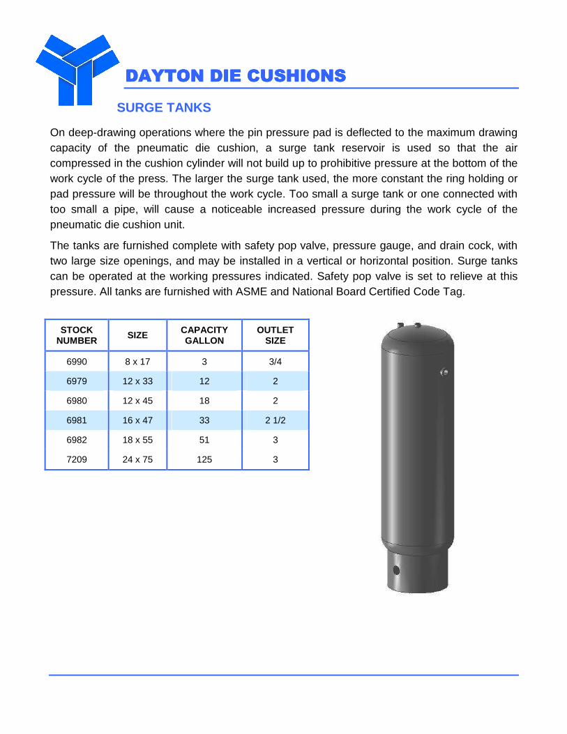
SURGE TANKS
On deep-drawing operations where the pin pressure pad is deflected to the maximum drawing capacity of the pneumatic die cushion, a surge tank reservoir is used so that the air compressed in the cushion cylinder will not build up to prohibitive pressure at the bottom of the work cycle of the press. The larger the surge tank used, the more constant the ring holding or pad pressure will be throughout the work cycle. Too small a surge tank or one connected with too small a pipe, will cause a noticeable increased pressure during the work cycle of the pneumatic die cushion unit.
The tanks are furnished complete with safety pop valve, pressure gauge, and drain cock, with two large size openings, and may be installed in a vertical or horizontal position. Surge tanks can be operated at the working pressures indicated. Safety pop valve is set to relieve at this pressure. All tanks are furnished with ASME and National Board Certified Code Tag.
STOCK NUMBER SIZE CAPACITY
GALLON OUTLET
SIZE
6990 8 x 17 3 3/4
6979 12 x 33 12 2
6980 12 x 45 18 2
6981 16 x 47 33 2 1/2
6982 18 x 55 51 3
7209 24 x 75 125 3
DAYTON DIE CUSHIONSDAYTON DIE CUSHIONSDAYTON DIE CUSHIONSDAYTON DIE CUSHIONS
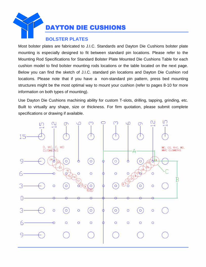
BOLSTER PLATES Most bolster plates are fabricated to J.I.C. Standards and Dayton Die Cushions bolster plate
mounting is especially designed to fit between standard pin locations. Please refer to the
Mounting Rod Specifications for Standard Bolster Plate Mounted Die Cushions Table for each
cushion model to find bolster mounting rods locations or the table located on the next page.
Below you can find the sketch of J.I.C. standard pin locations and Dayton Die Cushion rod
locations. Please note that if you have a non-standard pin pattern, press bed mounting
structures might be the most optimal way to mount your cushion (refer to pages 8-10 for more
information on both types of mounting).
Use Dayton Die Cushions machining ability for custom T-slots, drilling, tapping, grinding, etc.
Built to virtually any shape, size or thickness. For firm quotation, please submit complete
specifications or drawing if available.
DAYTON DIE CUSHIONSDAYTON DIE CUSHIONSDAYTON DIE CUSHIONSDAYTON DIE CUSHIONS
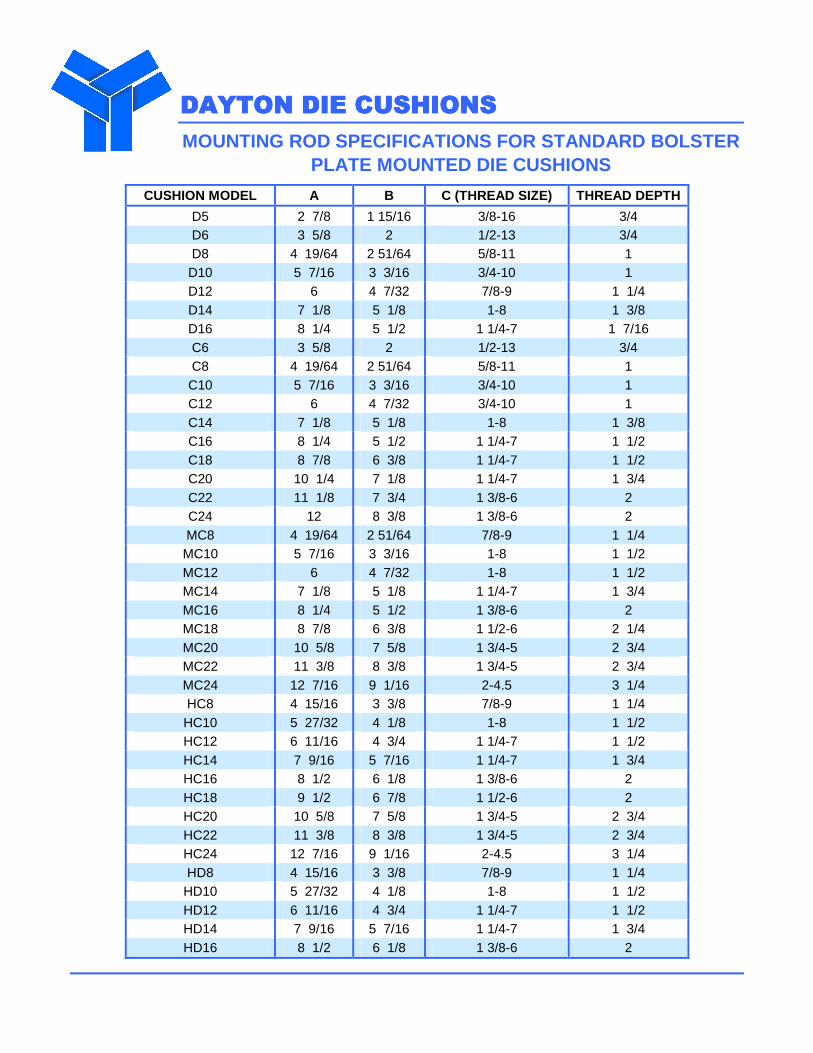
MOUNTING ROD SPECIFICATIONS FOR STANDARD BOLSTER PLATE MOUNTED DIE CUSHIONS
CUSHION MODEL A B C (THREAD SIZE) THREAD DEPTH
D5 2 7/8 1 15/16 3/8-16 3/4 D6 3 5/8 2 1/2-13 3/4 D8 4 19/64 2 51/64 5/8-11 1 D10 5 7/16 3 3/16 3/4-10 1 D12 6 4 7/32 7/8-9 1 1/4 D14 7 1/8 5 1/8 1-8 1 3/8 D16 8 1/4 5 1/2 1 1/4-7 1 7/16 C6 3 5/8 2 1/2-13 3/4 C8 4 19/64 2 51/64 5/8-11 1 C10 5 7/16 3 3/16 3/4-10 1 C12 6 4 7/32 3/4-10 1 C14 7 1/8 5 1/8 1-8 1 3/8 C16 8 1/4 5 1/2 1 1/4-7 1 1/2 C18 8 7/8 6 3/8 1 1/4-7 1 1/2 C20 10 1/4 7 1/8 1 1/4-7 1 3/4 C22 11 1/8 7 3/4 1 3/8-6 2 C24 12 8 3/8 1 3/8-6 2 MC8 4 19/64 2 51/64 7/8-9 1 1/4 MC10 5 7/16 3 3/16 1-8 1 1/2 MC12 6 4 7/32 1-8 1 1/2 MC14 7 1/8 5 1/8 1 1/4-7 1 3/4 MC16 8 1/4 5 1/2 1 3/8-6 2 MC18 8 7/8 6 3/8 1 1/2-6 2 1/4 MC20 10 5/8 7 5/8 1 3/4-5 2 3/4 MC22 11 3/8 8 3/8 1 3/4-5 2 3/4 MC24 12 7/16 9 1/16 2-4.5 3 1/4 HC8 4 15/16 3 3/8 7/8-9 1 1/4 HC10 5 27/32 4 1/8 1-8 1 1/2 HC12 6 11/16 4 3/4 1 1/4-7 1 1/2 HC14 7 9/16 5 7/16 1 1/4-7 1 3/4 HC16 8 1/2 6 1/8 1 3/8-6 2 HC18 9 1/2 6 7/8 1 1/2-6 2 HC20 10 5/8 7 5/8 1 3/4-5 2 3/4 HC22 11 3/8 8 3/8 1 3/4-5 2 3/4 HC24 12 7/16 9 1/16 2-4.5 3 1/4 HD8 4 15/16 3 3/8 7/8-9 1 1/4 HD10 5 27/32 4 1/8 1-8 1 1/2 HD12 6 11/16 4 3/4 1 1/4-7 1 1/2 HD14 7 9/16 5 7/16 1 1/4-7 1 3/4 HD16 8 1/2 6 1/8 1 3/8-6 2
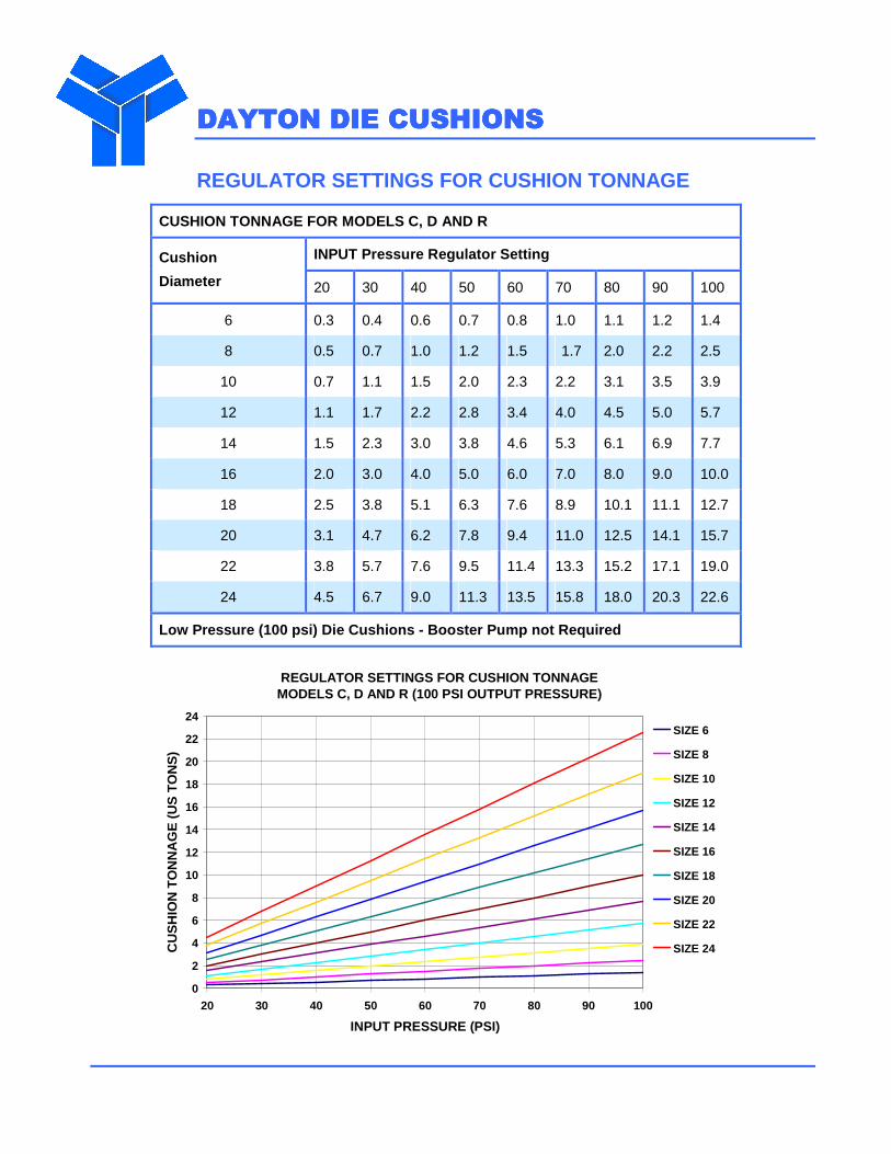
REGULATOR SETTINGS FOR CUSHION TONNAGE MODELS C, D AND R (100 PSI OUTPUT PRESSURE)
0
2
4
6
8
10
12
14
16
18
20
22
24
20 30 40 50 60 70 80 90 100
INPUT PRESSURE (PSI)
CU
SH
ION
TO
NN
AG
E (
US
TO
NS
)
SIZE 6
SIZE 8
SIZE 10
SIZE 12
SIZE 14
SIZE 16
SIZE 18
SIZE 20
SIZE 22
SIZE 24
DAYTON DIE CUSHIONSDAYTON DIE CUSHIONSDAYTON DIE CUSHIONSDAYTON DIE CUSHIONS
REGULATOR SETTINGS FOR CUSHION TONNAGE
CUSHION TONNAGE FOR MODELS C, D AND R
INPUT Pressure Regulator Setting Cushion
Diameter 20 30 40 50 60 70 80 90 100
6 0.3 0.4 0.6 0.7 0.8 1.0 1.1 1.2 1.4
8 0.5 0.7 1.0 1.2 1.5 1.7 2.0 2.2 2.5
10 0.7 1.1 1.5 2.0 2.3 2.2 3.1 3.5 3.9
12 1.1 1.7 2.2 2.8 3.4 4.0 4.5 5.0 5.7
14 1.5 2.3 3.0 3.8 4.6 5.3 6.1 6.9 7.7
16 2.0 3.0 4.0 5.0 6.0 7.0 8.0 9.0 10.0
18 2.5 3.8 5.1 6.3 7.6 8.9 10.1 11.1 12.7
20 3.1 4.7 6.2 7.8 9.4 11.0 12.5 14.1 15.7
22 3.8 5.7 7.6 9.5 11.4 13.3 15.2 17.1 19.0
24 4.5 6.7 9.0 11.3 13.5 15.8 18.0 20.3 22.6
Low Pressure (100 psi) Die Cushions - Booster Pump not Required
DAYTON DIE CUSHIONSDAYTON DIE CUSHIONSDAYTON DIE CUSHIONSDAYTON DIE CUSHIONS
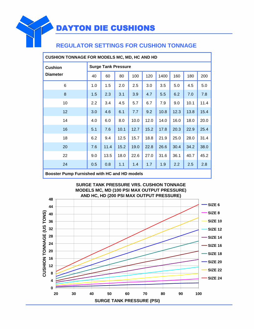
REGULATOR SETTINGS FOR CUSHION TONNAGE
CUSHION TONNAGE FOR MODELS MC, MD, HC AND HD
Surge Tank Pressure Cushion
Diameter 40 60 80 100 120 1400 160 180 200
6 1.0 1.5 2.0 2.5 3.0 3.5 5.0 4.5 5.0
8 1.5 2.3 3.1 3.9 4.7 5.5 6.2 7.0 7.8
10 2.2 3.4 4.5 5.7 6.7 7.9 9.0 10.1 11.4
12 3.0 4.6 6.1 7.7 9.2 10.8 12.3 13.8 15.4
14 4.0 6.0 8.0 10.0 12.0 14.0 16.0 18.0 20.0
16 5.1 7.6 10.1 12.7 15.2 17.8 20.3 22.9 25.4
18 6.2 9.4 12.5 15.7 18.8 21.9 25.0 28.0 31.4
20 7.6 11.4 15.2 19.0 22.8 26.6 30.4 34.2 38.0
22 9.0 13.5 18.0 22.6 27.0 31.6 36.1 40.7 45.2
24 0.5 0.8 1.1 1.4 1.7 1.9 2.2 2.5 2.8
Booster Pump Furnished with HC and HD models
SURGE TANK PRESSURE VRS. CUSHION TONNAGE MODELS MC, MD (100 PSI MAX OUTPUT PRESSURE)
AND HC, HD (200 PSI MAX OUTPUT PRESSURE)
0
4
8
12
16
20
24
28
32
36
40
44
48
20 30 40 50 60 70 80 90 100
SURGE TANK PRESSURE (PSI)
CU
SH
ION
TO
NN
AG
E (
US
TO
NS
)
SIZE 6
SIZE 8
SIZE 10
SIZE 12
SIZE 14
SIZE 16
SIZE 18
SIZE 20
SIZE 22
SIZE 24
DAYTON DIE CUSHIONSDAYTON DIE CUSHIONSDAYTON DIE CUSHIONSDAYTON DIE CUSHIONS
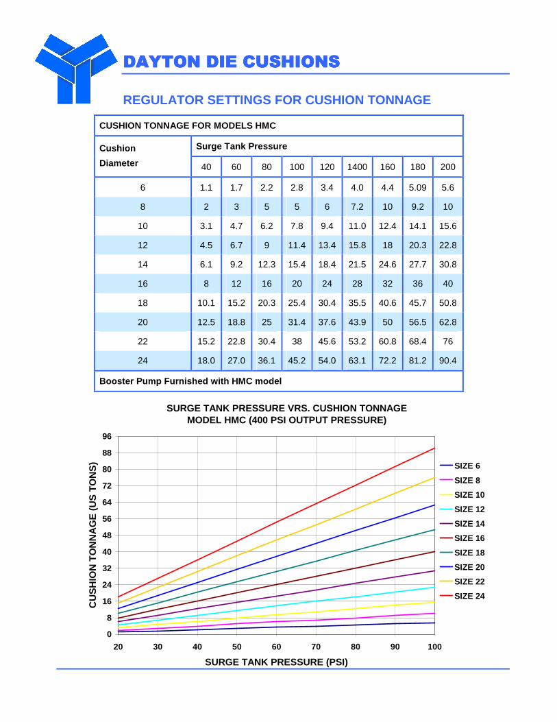
REGULATOR SETTINGS FOR CUSHION TONNAGE
CUSHION TONNAGE FOR MODELS HMC
Surge Tank Pressure Cushion
Diameter 40 60 80 100 120 1400 160 180 200
6 1.1 1.7 2.2 2.8 3.4 4.0 4.4 5.09 5.6
8 2 3 5 5 6 7.2 10 9.2 10
10 3.1 4.7 6.2 7.8 9.4 11.0 12.4 14.1 15.6
12 4.5 6.7 9 11.4 13.4 15.8 18 20.3 22.8
14 6.1 9.2 12.3 15.4 18.4 21.5 24.6 27.7 30.8
16 8 12 16 20 24 28 32 36 40
18 10.1 15.2 20.3 25.4 30.4 35.5 40.6 45.7 50.8
20 12.5 18.8 25 31.4 37.6 43.9 50 56.5 62.8
22 15.2 22.8 30.4 38 45.6 53.2 60.8 68.4 76
24 18.0 27.0 36.1 45.2 54.0 63.1 72.2 81.2 90.4
Booster Pump Furnished with HMC model
SURGE TANK PRESSURE VRS. CUSHION TONNAGE MODEL HMC (400 PSI OUTPUT PRESSURE)
0
8
16
24
32
40
48
56
64
72
80
88
96
20 30 40 50 60 70 80 90 100
SURGE TANK PRESSURE (PSI)
CU
SH
ION
TO
NN
AG
E (
US
TO
NS
) SIZE 6
SIZE 8
SIZE 10
SIZE 12
SIZE 14
SIZE 16
SIZE 18
SIZE 20
SIZE 22
SIZE 24
DAYTONDAYTONDAYTONDAYTON DIE CUSHIONS DIE CUSHIONS DIE CUSHIONS DIE CUSHIONS
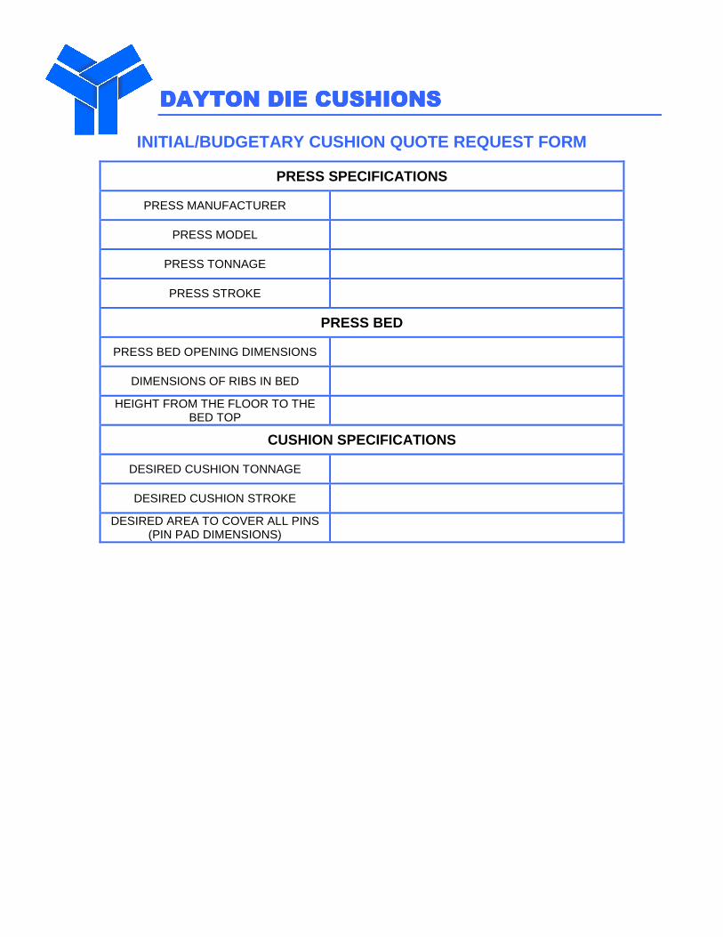
INITIAL/BUDGETARY CUSHION QUOTE REQUEST FORM
PRESS SPECIFICATIONS
PRESS MANUFACTURER
PRESS MODEL
PRESS TONNAGE
PRESS STROKE
PRESS BED
PRESS BED OPENING DIMENSIONS
DIMENSIONS OF RIBS IN BED
HEIGHT FROM THE FLOOR TO THE BED TOP
CUSHION SPECIFICATIONS
DESIRED CUSHION TONNAGE
DESIRED CUSHION STROKE
DESIRED AREA TO COVER ALL PINS (PIN PAD DIMENSIONS)
DAYTON DIE CUSHIONSDAYTON DIE CUSHIONSDAYTON DIE CUSHIONSDAYTON DIE CUSHIONS
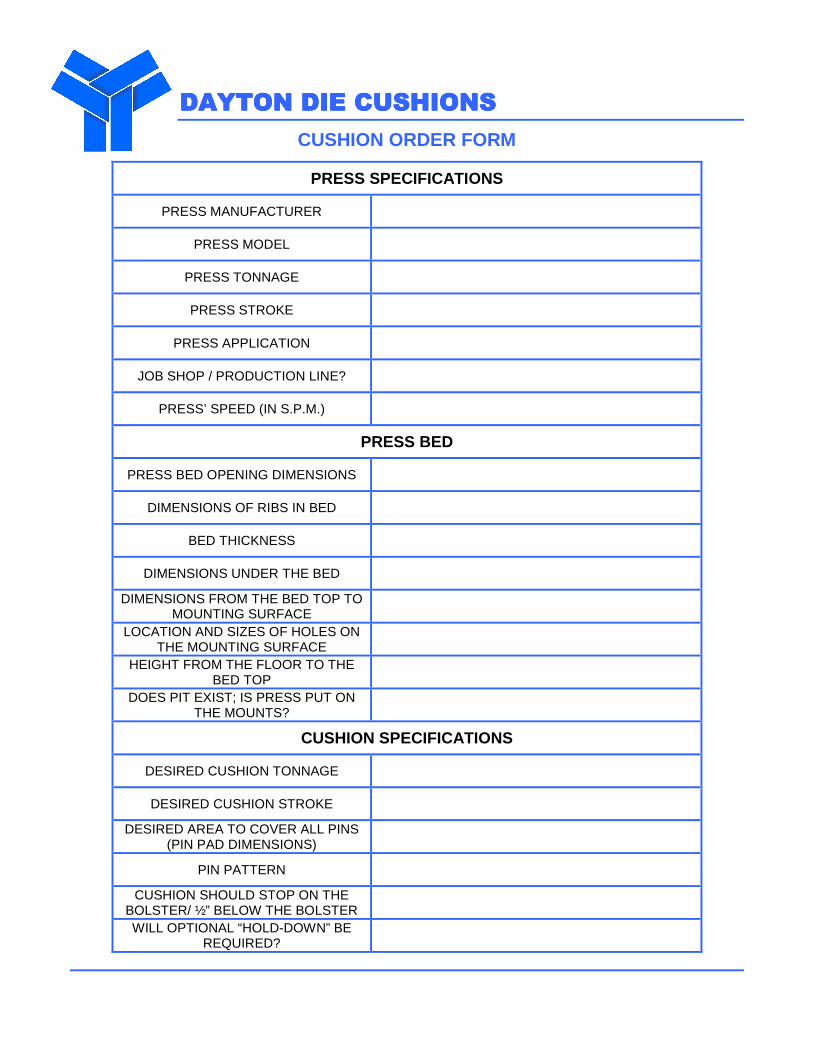
CUSHION ORDER FORM
PRESS SPECIFICATIONS
PRESS MANUFACTURER
PRESS MODEL
PRESS TONNAGE
PRESS STROKE
PRESS APPLICATION
JOB SHOP / PRODUCTION LINE?
PRESS’ SPEED (IN S.P.M.)
PRESS BED
PRESS BED OPENING DIMENSIONS
DIMENSIONS OF RIBS IN BED
BED THICKNESS
DIMENSIONS UNDER THE BED
DIMENSIONS FROM THE BED TOP TO MOUNTING SURFACE
LOCATION AND SIZES OF HOLES ON THE MOUNTING SURFACE
HEIGHT FROM THE FLOOR TO THE BED TOP
DOES PIT EXIST; IS PRESS PUT ON THE MOUNTS?
CUSHION SPECIFICATIONS
DESIRED CUSHION TONNAGE
DESIRED CUSHION STROKE
DESIRED AREA TO COVER ALL PINS (PIN PAD DIMENSIONS)
PIN PATTERN
CUSHION SHOULD STOP ON THE BOLSTER/ ½” BELOW THE BOLSTER
WILL OPTIONAL “HOLD-DOWN” BE REQUIRED?
DAYTON DIE CUSHIONSDAYTON DIE CUSHIONSDAYTON DIE CUSHIONSDAYTON DIE CUSHIONS
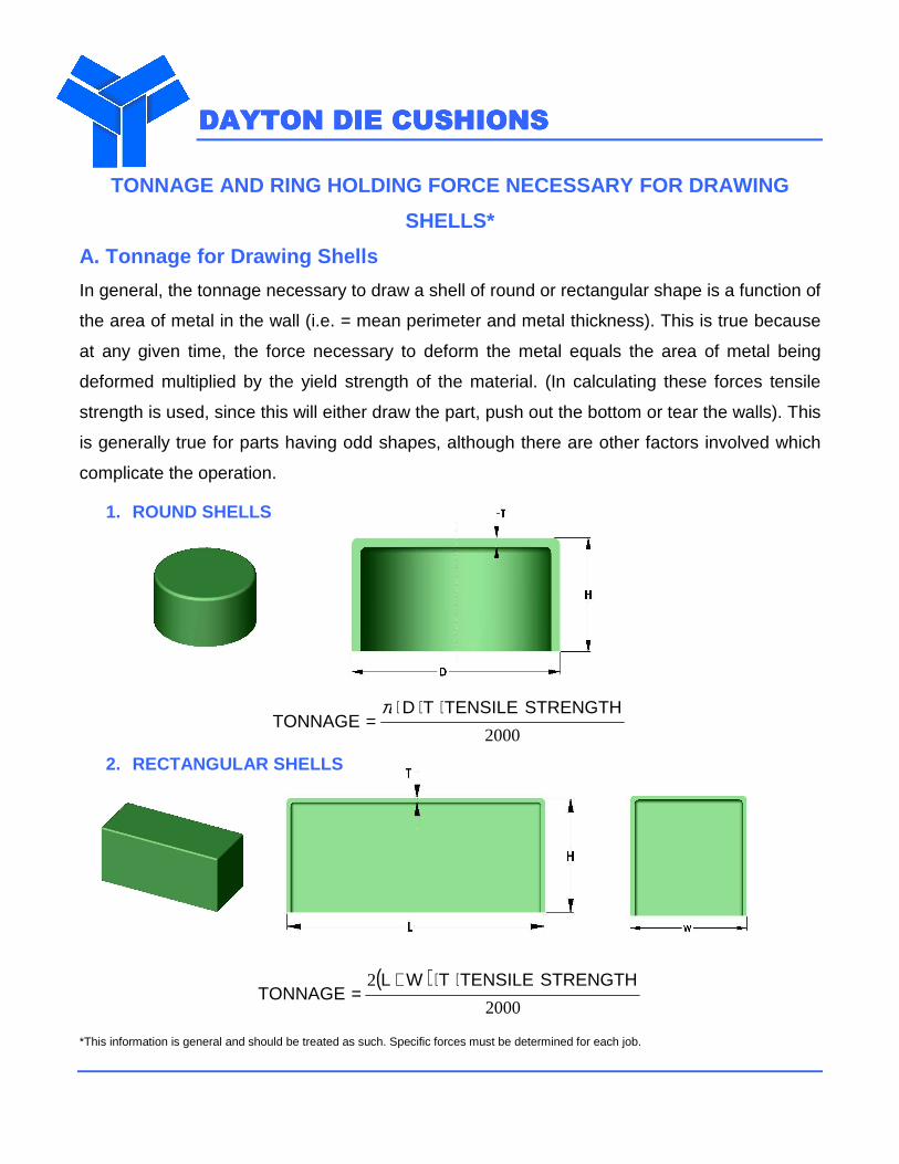
TONNAGE AND RING HOLDING FORCE NECESSARY FOR DRAWIN G
SHELLS*
A. Tonnage for Drawing Shells
In general, the tonnage necessary to draw a shell of round or rectangular shape is a function of
the area of metal in the wall (i.e. = mean perimeter and metal thickness). This is true because
at any given time, the force necessary to deform the metal equals the area of metal being
deformed multiplied by the yield strength of the material. (In calculating these forces tensile
strength is used, since this will either draw the part, push out the bottom or tear the walls). This
is generally true for parts having odd shapes, although there are other factors involved which
complicate the operation.
1. ROUND SHELLS
2000
STRENGTHTENSILETDTONNAGE
⋅⋅⋅=
π
2. RECTANGULAR SHELLS
( )2000
2 STRENGTHTENSILETWLTONNAGE
⋅⋅+=
*This information is general and should be treated as such. Specific forces must be determined for each job.
DAYTON DIE CUSHIONSDAYTON DIE CUSHIONSDAYTON DIE CUSHIONSDAYTON DIE CUSHIONS
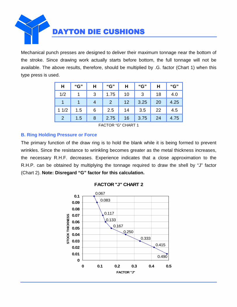
Mechanical punch presses are designed to deliver their maximum tonnage near the bottom of
the stroke. Since drawing work actually starts before bottom, the full tonnage will not be
available. The above results, therefore, should be multiplied by .G. factor (Chart 1) when this
type press is used.
H “G” H “G” H “G” H “G”
1/2 1 3 1.75 10 3 18 4.0
1 1 4 2 12 3.25 20 4.25
1 1/2 1.5 6 2.5 14 3.5 22 4.5
2 1.5 8 2.75 16 3.75 24 4.75
FACTOR “G” CHART 1
B. Ring Holding Pressure or Force
The primary function of the draw ring is to hold the blank while it is being formed to prevent
wrinkles. Since the resistance to wrinkling becomes greater as the metal thickness increases,
the necessary R.H.F. decreases. Experience indicates that a close approximation to the
R.H.P. can be obtained by multiplying the tonnage required to draw the shell by “J” factor
(Chart 2). Note: Disregard “G” factor for this calculation.
FACTOR "J" CHART 2
0.133
0.117
0.083
0.067
0.167
0.250
0.333
0.415
0.4900
0.01
0.02
0.03
0.04
0.05
0.06
0.07
0.08
0.09
0.1
0 0.1 0.2 0.3 0.4 0.5
FACTOR "J"
ST
OC
K T
HIC
KN
ES
S
.
DAYTON DIE CUSHIONSDAYTON DIE CUSHIONSDAYTON DIE CUSHIONSDAYTON DIE CUSHIONS
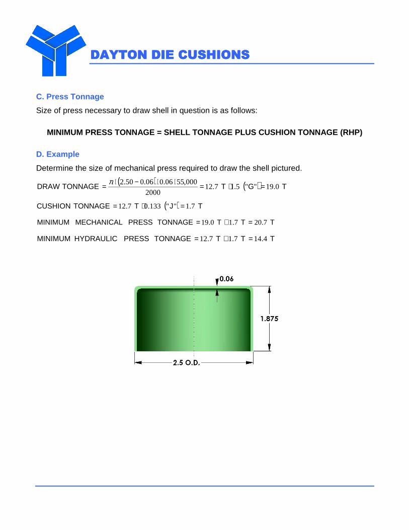
C. Press Tonnage
Size of press necessary to draw shell in question is as follows:
MINIMUM PRESS TONNAGE = SHELL TONNAGE PLUS CUSHION TONNAGE (RHP)
D. Example
Determine the size of mechanical press required to draw the shell pictured.
( ) ( ) TGTTONNAGEDRAW 0.19""5.17.122000
000,5506.006.050.2 =⋅=⋅⋅−⋅= π
( ) TJTTONNAGECUSHION 7.1""133.07.12 =⋅=
TTT TONNAGE PRESS MECHANICAL MINIMUM 7.207.10.19 =+=
TTT TONNAGEPRESS HYDRAULICMINIMUM 4.147.17.12 =+=