Die cast clamping system
94
Die cast clamping system
Transcript of Die cast clamping system

Die cast clamping system

Pascal Die cast clamping system
model TYB model TYB-Z / TYB-R model MGA
model ESTE-D model ECTE-D
model MGE model MEDmodel MDL
T-slotted manual slide type of clamp.
Clamping stroke 10~12mm model TYB
Automatic slidable clamp with air cylin-der. It enables to shorten the die change time.
Clamp system which absorbs and fixes a die with strong magnet.
model HCL(For medium and large-sized machine)
model HCS (For small and medium-sized machine)
Air-driven hydraulic control unit of the electric control(solenoid operation), combined with Pascal pump and Pascal non leak valve unit.
Control unit
Ball lock coupler
The system that can instantly detach or attach the machine ejector plate and die ejector plate by the magnet.
Automatic connection of ejector cylinder and plate (A and B) on die side by con-necting and disconnecting the rod.
C-plate mag clamp
Operation panel and Control box for hydraulic clamp. It simply displays the interlock state of clamp.
Operation panel Control box
Hydraulic clamp Mag clamp
Control system
Ejector related systemPositioning device
Operation panel & Control box
Elevating positioning block. It enables to perform the horizontal and vertical posi-tioning surely and easily by placing a die on die setter.
Die setter
1
page → 21
page → 29
page → 41
page → 17
page → 27
page → 35
page → 33
page → 32page → 31
page → 51

Pascal Die cast clamping system
model SMR / SMF model KC / KF
Automatic connection and disconnection of multiple couplers and electric con-nectors together at once.
Multi coupler which can be connected securely at once by pushing the gripper slightly with hand.
Die is changeable quickly and securely, comparing to the conventional forklift or overhead crane.
Dies and large sized components can be rotated safely and quickly.
Innovative die-casting hydraulic cylinder with high durability, excellent main-tainability and compact size, comparing to the conventional hydraulic cylinder.
Auto coupler Multi coupler Die changer
Die rotator Die-casting hydraulic cylinder
Other products
2
page → 61
page → 83
page → 55
page → 81
page → 77

6,500kN(650ton) Die-casting machine fixed side Hydraulic clamp TYB100
3

Pascal clamp model TYB
4

8,500kN(850ton) Die-casting machine movable side C-plate mag clamp & Hydraulic clamp TYB160
C-plate mag clampg
5

Pascal clamp
model TYB
6

3,500kN(350ton) Die-casting machine Mag clamp
Mag clamp
7

8

16,500kN(1,650ton) Die-casting machine Die for die-casting machine 3 piece cylinder KC
3 piece cylinder KCy
9

3 piece cylinder KCp y
10

8,500kN(850ton) Die-casting machine fixed side Hydraulic clamp TYB-Z
Pascal clamp
model TYB-ZPascal clamp
TYB Z
Hydrau l i c c l amp TYB -Z
11

8,500kN(850ton) Die-casting machine movable side C-plate mag clamp & Hydraulic clamp TYB-Z
C-plate mag clampp g p
Pascal clamp
model TYB-Z
C -p l a t e mag c l amp & Hyd rau l i c c l amp TYB -Z
12

By means of the automation of die clamp.The reduction of non-productive time (set up time) can be fulfilled.
Pascal clampmodel TYB
Pascal clamp enables to shorten the die change time and improves productivity and enhances the operating rate of production. For a typical introduction example, it shortens the die change time from 60 minutes to 30 minutes for medium and large sized machine. In addition, it enables to reduce numbers of operators and workload.
Die removalDie unload, load(operation with overhead crane)
Die unload, load(operation with overhead crane)
Die installation Other set up
Other set upAutomation of clamp/unclamp
・Preparation of tools
・Bolt removal
・Transfer between the operate
side and opposite operate side
・Bolt tightening
・Transfer between the operate
side and opposite operate side
・Tools removal
・Coupler
disconnection
Pascal clampmodel TYB
Movable side Fixed side
・Coupler
disconnection
Screw (conventional)
Automatic c lamp
13
Pascal Clampmodel TYB
5,000kN(500ton)Die-casting machine
14

5,000kN(500ton)Die-casting machine Hydraulic clamp, slidable type TYB
T-slotted slidable clamp with compact body and long clamp stroke, equipped with a strong clamping force and high rigidity to resist shock.
model TYBClamping stroke:10 ~ 12 mm
Clamping force:4, 6, 10, 16, 25 ton
● Long clamping stroke
● Perfect protection against dust or die release agents.
● Best solution for heat and corrosion
TYB Hydraul ic c lamp, s l idable type
Hy
dra
uli
c c
lam
p,s
lid
ab
le
typ
e T
YB
15
page → 17

A A
A - A
Die
Stroke10 ~ 12 mm
Hydraulic piston
Non-breathingRam-cylinder
Secure unclamping operation
Lever shaft
Dust seal
Dust seal
(Ion-Nitriding)
Grease nippleFor lubrication for clamplever and shaft (option).
Protect from intrusion of release agents and foreign substances into the hydraulic cylinder. (Ion-Nitriding)
Durable return spring is locatedat dust and vapor free area of the clamp body so that it can exert a stable pulling force.
Long clamping strokeIt can accommodate big tolerance of clamping height and T-slot dimensions.
It is hard chrome plated, which enhances abrasion and corro-sion resistant performance.
Dust coverProtect from release agentsand foreign substances.
TYB Hydraul ic c lamp, s l idable type
It has high reliability and durability capable of enduring severe use conditions such as high temperature, foreign substances and release agent scattering.
Dust proof seal/cover and viton seals are provided to protect from high temperature (under 120℃).
Structure
Hy
dra
ulic
cla
mp
,
slid
ab
le ty
pe T
YB
16

Clamp TYB
T-slot
Clamping stroke:10 ~ 12 mmClamping force:4, 6, 10, 16, 25 ton
model TYB
■ Special type■ Model designation
Die
TYB 063
Clamping force1
TYB Hydraul ic c lamp, s l idable type
● Safety stroke and clamping stroke shown above are subject to change depending on dimensions of die and T -slot.● Weight varies according to the dimension of clamp T-leg and die plate thickness h.
1 Specifications
Model TYB040 TYB063 TYB100 TYB160 TYB250Clamping force (at 24.5 MPa) kN 39.2 61.7 98 156 245
Full stroke mm 10 10 12 12 12
Clamping stroke mm 4 4 4 4 4
Safety stroke mm 6 6 8 8 8
Cylinder capacity (at full stroke) cm3 16.5 26.1 47.2 78.2 130
Proof pressure MPa 36.7
Max. hydraulic pressure MPa 24.5
Operating temperature ℃ 5 ~ 120
Weight kg 4.5 9 15 25 45
Hy
dra
uli
c c
lam
p,
sli
da
ble
ty
pe
TY
B
17
Refer to page → 19

51
P
Q
N
K
ML
DJ
ET
XF V
YZ
GC
SR
B
A
b
ch
dj
a
Handle
Projection length of T-leg allowance at clamped condition Q
Hydraulic port 2-Rc1/4
Die
T-slot dimension and die plate thickness
● Specify T-slot dimensions (a, b, c, d, j) and die plate thickness (h).
● Regarding "d" dimension of T-slot, for retrofit : specify to 0.1 mm. For new machine : machining tolerance shall be ±0.2 mm.
● Dimensions (A, B, C, D, J) shall be determined according to T-slot dimensions.
Die plate
thickness
h
TYB Hydraul ic c lamp, s l idable type
● When newly machining T-slot, it is recommended to apply the dimensions specified on page →25.● Height of lever F varies according to the dimension of h. ● Min. J dimension varies according to body materials. (Standard:SS400, S1:S45C, S2:SCM435) ● Special specifications are prepared in case “h” dimension is out of the range.
Dimensions
mm
Model TYB040 TYB063 TYB100 TYB160 TYB250
Height of lever F range of h inside the brackets
27.5 (45≦h) 29.5 (50≦h) 45 (58≦h) 60 (58≦h) 106 (58≦h)
32.5 (40≦h<45) 39.5 (40≦h<50) 55 (48≦h<58) 70 (48≦h<58) 116 (48≦h<58)
37.5 (35≦h<40) 49.5 (30≦h<40) 65 (38≦h<48) 80 (38≦h<48) 126 (38≦h<48) G 13 13 14 15 20K 145 168 200 235 285L 23 30 30 30 35M 122 138 170 205 250N 16 20 20 20 20P 32.5 38 62 80 95
Projection length of T-leg allowance at
clamped condition Q32 36 45 55 65
R 83 103 113 133 168S 39.6 49.6 54.6 59.6 72T 64.5 71.5 94.5 110 156V - 58 76 96 118
Min. E 76.5 83.5 107 122 168Full stroke X 10 10 12 12 12
Clamping stroke Y 4 4 4 4 4Safety stroke Z 6 6 8 8 8
Min. J Standard:10.5 S1 : - S2 : 9
Standard:14. S1:11.4 S2 : 9.5
Standard:16 S1 :13 S2 :11
Standard:19 S1 :15.5 S2 :13
Standard:26 S1 :21.5 S2 :18
h(Min. ~ Max.) 35 ~ 50 30 ~ 60 38 ~ 70 38 ~ 70 38 ~ 70
Hy
dra
ulic
cla
mp
,
slid
ab
le ty
pe
TY
B
18

Low distance lever
Operating temperature : 5 ~ 120℃
It is applied under condition that the die plate thickness is thinner than standard.
It is applied undercondition that the dieplate thickness is thickerthan standard.
It is applied under condition that the die and its surroundings are in high temperature.
Clamp lever high distance type □TYB -HH
Wide lever
Wide lever □TYB -WW
Die detectionlimit switch
It prevents clamp misplace.
Die detection limit switch
it is applied under condition that hydraulic connection port is connected with NPT thread.
N NPT port □TYB -N
High temperature □TYB -VV
T Low distance clamp type □TYB -THandle
Only for TYB040-250. It is not applicable for TYB010 and TYB020.
□TYB -GG With handle
Cover
It is applied to protect from release agent and foreign substances.
□TYB -DD With dust cover
Hydraulicport
It is applied under condition that there is interference on clamp side and it can not be connected with side hydraulic port (standard specification).
□TYB -JJ Rear piping type
NPT thread
For lubrication for clamp lever and shaft (Option).
P With grease nipple □TYB -P
Grease nipple
It is applied under condition that the T-slot dimension is under standard and the strength is insufficient.
S1 S2 Body strengthened
Body
TYB -S1, TYB -S2□ □
TYB -S1□TYB -S2□
:S45C:SCM435
It is applied with U cut(cut out) in the die.
TYB Hydraul ic c lamp, sl idable type special t ype
Hyd
rau
lic c
lam
p,s
lida
ble
typ
e
TY
B s
pe
cia
l ty
pe
19

Hyd
rau
lic clam
p,slid
ab
le typ
e
TY
B sp
ecia
l type
20
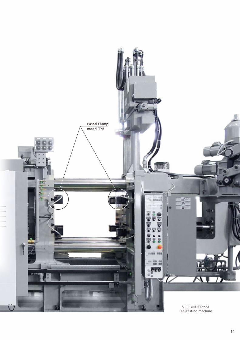
6,500kN(650ton)Die-casting machine Hydraulic clamp, automatic slidable type TYB-Z
Die
Die
Air cylinder
Lever
Dust cover Dust cover
● Unclamp
● Clamp
Automatic slidable clamp with an air cylinder. It enables to shorten the die change time.
TYB-Z/TYB-R Hydraul ic c lamp, automat ic s l idable type
Hyd
raul
ic c
lam
p,au
tom
atic
slid
able
type
TY
B-Z/
TYB
-R
21

■ Special type
D With dust coverJ Rear piping type
S1 Body strengthened(S45C)S2 Body strengthened(SCM435)
T Low distance clamp type
V High temperature
W Wide lever
P With grease nippleN NPT port
Clamp TYB-R
Clamp TYB-Z
T-slot
Air cylinder
Air cylinderLimit switch
T-slot
Limit switch
Air cylinder position
TYB R040■ Model designation
Clamping force
Slide direction
Air cylinder position
L 150-
Sliding stroke(mm)
Air cylinder
Air cylinderR : Right side
L : Left side
R: Vertical Z: Horizontal
1
2
3
3
4
Control unit HCL-T33-position center exhaustair solenoid valve equipped
* The control method is different between TYB-Z and TYB-R.
Control unit HCL-T22-position double air solenoid valve equipped
Mountingbracket
Die Die
TYB-Z/TYB-R Hydraul ic c lamp, automat ic s l idable type
TYB-Z
Slide direction:Horizontal Slide direction:Vertical
TYB-R
● Mass varies according to specifications. Contact Pascal for the details.*1 : Contact Pascal for the sliding stroke which is not mentioned above. *2 : Proximity switch and auto switch is not applied to a heat proof type.
1 Specifications4
Model TYB040Z TYB063Z TYB100Z TYB160Z TYB250Z
TYB040R TYB063R TYB100R TYB160R TYB250RClamping force (at 24.5 MPa) kN 39.2 61.7 98.0 156 245
Full stroke mm 10 10 12 12 12
Clamping stroke mm 4 4 4 4 4
Safety stroke mm 6 6 8 8 8
Cylinder capacity (at full stroke) cm3 16.5 26.1 47.2 78.2 130
Proof pressure MPa 36.7
Max. hydraulic pressure MPa 24.5
Standard sliding stroke *1 mm 50, 75, 100, 125, 150
50, 75, 100, 125, 150, 200 50, 75, 100, 125, 150, 200, 250, 300
Slider driving air pressure MPa 0.39 ~ 0.54
Clamp sliding speed mm/s 30 ~ 80 ( Adjusted by a flow control valve )
Operating temperature ℃ 0 ~ 70 (5 ~ 120 by heat proof type *2)
Hydraulic clam
p,automatic
slidable type TYB
-Z/
TYB
-R
22

At standby At standby
When forwarding
Air cylinder Air cylinder
When forwarding
Limit switch(die detection proximity switch)
Limit switch(die detection proximity switch)
TYB-Z/TYB-R Hydraulic clamp, automatic slidable type specification example
Automatic s l idable type Automatic s l idable type with l imit switch (Die detection proximity switch)
Hyd
raul
ic c
lam
p,au
tom
atic
slid
able
type
TY
B-Z/
TYB
-R
23

At standby
Limit switch(backward end detection proximity switch)
Limit switch(die detection proximity switch)
Air cylinder
Limit switch(backward end detection proximity switch)
When forwarding
Limit switch(die detection proximity switch)
TYB-Z/TYB-R Hydraulic clamp, automatic slidable type specification example
* Configuration varies according to specifications. Contact Pascal for the details.
With l imit switch (die and backward end detection proximity switch)
Hydraulic clam
p,automatic
slidable type TYB
-Z/
TYB
-R
24

a
b
hc
dj
H
L AA
h
Die
T-slot and cutout detai ls
● Process with the below dimension in case of machining T-slot newly.
● Contact Pascal if your T-slot dimensions are less than Min. T-slot dimensions shown below. The main body materials shall be changed and code is S1 and S2 for a special spec.
● To accommodate the clamp to the die as s h o w n o n t h e r i g h t , P a s c a l c a n p r o v i d e a s p e c i a l d e s i g n e d c l a m p l e v e r w i t h t h e clamp.
● Specify the dimension H, L and h of the die when order ing. The f igures shown in the column L and H in the table are a minimum dimension to make.
Clamp area details
Recommended T-slot
ModelTYB040 TYB063 TYB100 TYB160 TYB250TYB040Z TYB063Z TYB100Z TYB160Z TYB250ZTYB040R TYB063R TYB100R TYB160R TYB250R
Min. H
20≦h<25 mm 20 - - - -
25≦h<30 mm 25 25 35(30) - -
30≦h<35 mm 25 30 35 - -
35≦h<40 mm 25 30 35 - -
40≦h<45 mm - 30 40 40(30) -
45≦h<50 mm - - - 40(30) -
50≦h mm - - - 45(35) 50
Min. L mm 15 20 20 25(20) 30
AA mm 10 12.5 12.5 10(12.5) 10
Model TYB040 TYB063 TYB100 TYB160 TYB250TYB040Z TYB063Z TYB100Z TYB160Z TYB250ZTYB040R TYB063R TYB100R TYB160R TYB250R
Recommended T-slot dimension
a mm 22 28 28 32 36
b mm 37 46 46 53 56
d mm 22 28 28 28 32
j mm 16 20 20 24 30
Minimum T-slot dimensions
a mm 15 19 23 27 32
d mm 14 16 18 21 29
j mm 11.5 15 17 20 23
+0.5 0
+3 0
±0.2
+2 0
+0.5 0
+4 0
±0.2
+2 0
+0.5 0
+4 0
±0.2
+2 0
+0.5 0
+4 0
±0.2
+2 0
+0.5 0
+4 0
±0.2
+2 0
T-s
lot
an
d C
uto
ut
de
tails
25

Wiring
Clamp circuit 1
Control unitHCSD-HG2SSS
Air 0.47MPa
Control boxECTE-D
OperationpanelESTE-D
Clamp circuit 2
Clamp circuit 1
To sensor of clampTo machine
Primary power
F i x ed p l a t enMovab l e p l a t en
Guide block
T-slot
Clamp TYB
Die
Select ion of hydraul ic c lamp
● Regarding Control unit, refer to page →27, Operation panel page →31, and Control box page →32.*1 : Quantity for one machine.*2 : Clamping force per platen. (For half of the quantity mentioned above.) Inquire the clamp selection, when the actual die opening
force is greater than above value.
Selecting table for clamp and control unitDie-casting machines Die clamping force kN ~2000 ~3500 ~5500 ~8500 ~13000 ~20000 ~26000
Clamp
Model × Quantity *1
TYB040 × 8TYB040Z × 8TYB040R × 8
TYB063 × 8TYB063Z × 8TYB063R × 8
TYB100 × 8TYB100Z × 8TYB100 R × 8
TYB160 × 8TYB160Z × 8TYB160 R × 8
TYB250 × 8(TYB160 × 12)TYB250Z × 8(TYB160Z × 12)TYB250R × 8(TYB160R × 12)
TYB250 × 8(TYB160 × 12)TYB250Z × 8(TYB160Z × 12)TYB250R × 8(TYB160R × 12)
TYB250 × 16TYB250Z × 16TYB250R × 16
Total clamping force *2 kN 156 246 392 624 980
(936)1470(1248) 1960
Hydraulic control unit HCSD-HG2SSS / HCLD-HG2SSS HCLD-HG22SSS
Se
lectio
n o
f h
ydra
ulic cla
mp
26

A2
A1
A3
S
S
S
A2
A1
A3
X
X
X
HCS G2 SD - - US SH
Control voltage DC24V
Hydraulic gauge for each circuit
Hydraulic circuit * Indicated in 1-4 alphabets.
Pascal pump
Mo d e l d e s i g n a t i o n
SSS circuitXXX circuit
* In case of other solenoid valve voltage, contact Pascal separately. In case of AC voltage, CE and UL standard are not applicable.
12
3
Hydraulic pressurecircut
Hydraulic pressurecircut
Pascal Control unit For small and medium-sized die-casting machineHCS
● Fluid : water glycol system working oil
Specifications
1 Pascal pump (model × quantity)
: Without
: WithU
With hydraulic gauge for each circuit
32 Hydraulic circuit
Clamp circuit Single solenoid valve + relief valve: X Double solenoid valve + relief valve: S
For use of mineral oil, contact Pascal separately.
: X6308UG×1unitG2
Model HCSD-HG2□-□Pump model × quantity X6308UG × 1unit
Valve switching system Pilot air
Discharge pressure MPa 24.5
Driving air pressure MPa 0.47
Discharge volume (at no load) L /min 1.3
Oil tank capacity L LOW-LEVEL:1.5 / UPPER:3.5
Set pressure of pressure switch MPa 14.7 (INC.)
Set pressure of relief valve MPa 27.9
Air consumption rate Nm3/min Max. 0.4
Operating temperature ℃ 5 ~ 50
Number of clamp circuit Pascal pumpmodel × quantity
Control unit model
Fixed side Movable side Single solenoid valve Double solenoid valve1 X6308UG × 1unit X S
1 1 X6308UG × 1unit XX SS
1 2 X6308UG × 1unit XXX SSS
2 2 X6308UG × 1unit XXXX SSSS
Control unit
HCS
27

378.3
345
150
27.5
15B (49) (49) 116
1523.5A
83
205
315
1532015
23.5
60
109.5
202.6
200
545
214
134.7
109.5
260
6.8
10 10320
370350
27 30 27.5
150
M10
310350
680
↑A
100 30160
3012
20
100
Oil inlet Pascal pump
Conduit ø28
Pressure switchTerminal board
Eyebolt (M8)
Filter regulator
Oillevel gauge
4-ø11M10 Mounting bolt hole
Air bleeding valve
Relief valvePascalnon leak valve Hydraulic port Rc1/4
Drain portRc1/4
Air supply port Rc1/4
Conduit connection
port position
154.7
Anti vibration rubber:ZPS-B5
Anti vibration rubber (option)model ZPS-B5
Stand (option)model ZPS-S0
Pascal pumpspace for maintenance
Return portwith check valve
Air solenoid valvefor clamp control
View A
HCS Pascal Control unit For small and medium-sized die-casting machine
● The drawings showing : HCSD-HG2SSS.
For 4 circuits application, contact Pascal
for details.
● Model HCL should be chosen in case of the following cases.1. Double pump type is required. 2. The signal of abnormal high pressure is required for interlocking.3. More than five circuits of hydraulic valve are required.
Number of hydraulic circuit 1 2 3 4
A mm 350 350 350 400
B mm 234 185 136 137
Weight kg 18 21 24 27
Control unit
HC
S
28

A2
A1
A3
S
S
S
A2
A1
A3
X
X
X
HCL G2 SD - - LS SH
Control voltage DC24V
Special specification
Hydraulic circuit * Indicated in 3-4 alphabets.
Pascal pump
Mo d e l d e s i g n a t i o n
* It can not correspond to voltage other than DC24 V.
XXX circuit
Hydraulic andair pressure circuit
1
2
3
SSS circuit
Hydraulic andair pressure circuit
HCL Pascal Control unit For medium and large-sized die-casting machine
: Low oil level detection switchL
: 2-position double air solenoid valve equipped × 2 (for vertical clamp slider and die positioning pin)
T2
: 3-position center exhaust air solenoid valve equipped × 2 (for horizontal clamp slider)
T3
: Without
Special specification3: X6308UG×1unitG21
: X6308UG×2units G22
Pascal pump (model × quantity)For use of mineral oil, contact Pascal separately.
2 Hydraulic circuit
Specifications
Clamp circuit Single solenoid valve + relief valve: X Double solenoid valve + relief valve: S
● Fluid : water glycol system working oil
Number of clamp circuit Pascal pumpmodel × quantity
Control unit model
Fixed side Movable side Single solenoid valve Double solenoid valve1 2 X6308UG × 1unit XXX SSS
2 2 X6308UG × 1unit XXXX SSSS
1 2 X6308UG × 2units XXX SSS
2 2 X6308UG × 2units XXXX SSSS
Model HCLD-HG2□-□ HCLD-HG22□-□Pump model × quantity X6308UG × 1unit X6308UG × 2units
Valve switching system Air pilot system
Discharge pressure MPa 24.5
Driving air pressure MPa 0.47
Discharge volume (at no load) L /min 1.3 2.6
Oil tank capacity L LOW-LEVEL:1.5 / UPPER:3.5
Set pressure of digital pressure gauge MPa 14.7 / 30.8( at excessively high pressure)
Set pressure of relief valve MPa 27.9
Air consumption rate Nm3/min Max. 0.4 Max. 0.8
Operating temperature ℃ 5 ~ 50
Control unit
HCL
29

290
45
84
83
430
412
429.9
160
27.5
215
15460
49 49 49 L15
3365
1540015119.5
242
200
555
167.5
283.5
224.5
10.5
237.1
119.5
1515
160
27.530 35
ø60
M12
140 30
200
200
2525
204.5
140
34.5
15
100
26045.595
25 25
30200 15
260
Conduit connection
port position
200.5
4-ø14M12 Mounting bolt hole
Oil inlet Air pressure gaugeStop valve
Pascal pump
Anti vibrationrubber:ZPS-B6
Stand:ZPS-PZXA7320Stand:ZPS-S4
Air solenoid valvefor clamp control
Digitalpressure switch *1
TerminalboardConduit ø22
Conduit ø28
4-ø14M12 Mountingbolt hole
Filter regulator
Non-leak valve
Oil levelgauge
Air bleeding valve Hydraulic portRc1/4Relief valve
Drain portRc1/4
Air supplyport Rc3/8 *2
Return portwith check valve
Anti vibration rubber(option)
model ZPS-B6
Stand(option)
model ZPS-S4 model ZPS-PZXA7320
Pascal pumpspace for maintenance
*460*430
*410
*410
*460
*460
Stand(option)
Eyebolt (M8)
HCL Pascal Control unit For medium and large-sized die-casting machine
● The drawings showing : HCLD-HG2SSSS For 5
circuits application, contact Pascal for details.
*1: Digital pressure gauge outputs the signal
of pressure build-up and excessive high
pressure.
*2: Piping diameter for 2 pumps.
(Rc1/4 is for 1 pump type.)
● Weight for 1 unit of pump (dried). 3kg to be added when 2 pumps are applied.
● The dimensions marked * in the diagrams are for 1 to 4 circuits applications. For 5 or more circuits, the dimension increases by 50mm at every additional circuit.
Number of hydraulic circuit 1 2 3 4
L mm 204 179.5 155 155
Weight kg 26 29 32 34
Control unit
HC
L
30

Pascal corporation
Pascal corporationPascal corporation
Pascal corporationPascal corporation
Pascal corporation
105 20
140
100 60 100
190 160
100 3530
150
100
60
190
140 62.3
150
Mounting bracket
[ For vertical and horizontal loading ]
Hang downtype
Embeddedtype
Self-standing typeL type Wall mount type
Operation panel dimensions
User friendly control panels
with compact body and clear
indication.
It can be installed to die-casting
machine or wall utilizing the rear
tap hole.
(M4 bolts×4 accessories)
ESTE-D Operat ion panel
Model ESTE-DLoading direction Vertical and horizontal loading
Weight kg 0.6
Operation panel
ES
TE
-D
31

190
180 120
50
270
370
180 110
270
Self-standing typeL type
Interlock
The following interlock is incorporated into the electric control circuit for hydraulic clamp, so the die changing operation can be performed safely.● The operation of hydraulic and air clamp is feasible only when all of conditions ①~⑥ shown below have become complete at time of die changing. Hydraulic clamp : ①Die change mode Die-casting machine : ②Set-up(or manual)mode, ③Nozzle retracted, ④Ejector retracted, ⑤Platen closed-end, ⑥Safety door closed The condition of die-casting machine for ②, ③ and ⑤ can be confirmed with LED lamp on operation panel.
Mounting bracket
ECTE-D Control box
Model ECTE-DWeight kg 4
Control box
EC
TE
-D
32

Clamp dies instantly with super strong permanent magnet
3,500kN(350ton) Die-casting machineMag clamp movable side
3,500kN(350ton) Die-casting machineMag clamp fixed side
3,500kN(350ton) Die-casting machine Mag clamp & Die setter
Pascal mag clamp is a die clamp system for die-casting machines that clamps a die with powerful magnet force.
As the mounting bolt and mounting space for automatic clamp are not required, the die-casting machine surface can be maximized.
Mag clamp(Magnet c lamp)
Mag clamp
MGA
33

S N
NS
N S
SN
SN
N N S
NS
S NSS
NS
N Neodymium magnet
Alnico magnet
Electromagnetic coil
Magnet core
Clamp plate
C l amp(Magne t i z ed) Unc l amp(Demagne t i z ed)
Lines of magnetic flux
Effective height of magnetic flux : approx 20mmPlate thickness
35mm
50 mm
52 mm
Die Die
Super strong permanent magnet
Inverts the polarity by electromagnetic coil.
Inverts the polarityof alnico magnet.
Powerfully adheres die.
Electromagnetic coil is energized for 0.5 sec.
Polarity of alnico magnet is inverted.
Neodymium magnet and alnico magnet become homopolar.
Magnet core becomes a strong magnet to clamp the die.
1
2
3
4
1
2
3
Electromagnetic coil is energized for 0.5 sec.
Polarity of alnico magnet is inverted.
Magnetic flux of neodymium magnet and alnico
magnet is not emitted from the surface of mag-
net core so that the die can be unclamped.
● The clamp plate is one set of two plates for movable platen and fixed platen sides.
● Die can be adhered and detached instantly (0.5-4.5 seconds).
● Energization is required only when switching on and off. No energization required
during clamped condition.
● Die displacement detection and die fall protection hook are equipped as standard.
● 0 ~ 180 for heat proof type.
Mag clamp(Magnet c lamp)
● Contact Pascal for the details.
Structure and function
Mag clamp
MGA
34

The lift of Die set block is operated.
It is mountable near the die-casting machine
control panel with L type bracket.
There is also a model integrated
with clamp and die setter.
Contact Pascal for details.
Die setteroperation panel
Die setter operation button
Clamp operation button
Die setter operat ion panel Die setter & Clamp Operation panel
Die setter
3,500kN(350ton) Die-casting machine Die setter & Mag clamp
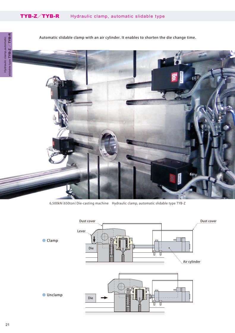
An elevating positioning block
Introducing a Die setter, the horizontal and vertical positioning can be determined surelyand easily by placing a die on a Die setter and it improves the productivity and set up.
Die set ter PAT.MDL
Die setter
MD
L
35
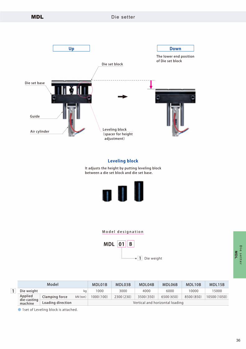
MDL 01 B
Die set block
The lower end positionof Die set block
Leveling block(spacer for height adjustment)
Guide
Die set base
Up Down
Air cylinder
Leveling blockIt adjusts the height by putting leveling block between a die set block and die set base.
Die weight
Mo d e l d e s i g n a t i o n
1
MDL Die set ter
● 1set of Leveling block is attached.
1Model MDL01B MDL03B MDL04B MDL06B MDL10B MDL15B
Die weight kg 1000 3000 4000 6000 10000 15000Applied die-casting machine
Clamping force kN(ton) 1000(100) 2300(230) 3500(350) 6500(650) 8500(850) 10500(1050)
Loading direction Vertical and horizontal loading
Die setter
MD
L
36

Z
X
Y
Z
Y
X
Fixedplaten
Sleeve
Die
Die
Die
Bush
Sleeve
Bush
BushSleeve
Die Bush
Sleeve
Die center (X, Y) is not stable and hard to load a die. (Hard to position a sleeve and bush.)
By placing a die on the die setter, horizontal position (X) is determined
quickly and securely and die setting can be performed easily.
Die setter Die setter
Fixedplaten
MDL Die set ter
Die sett ing with s leeve and bush
Die sett ing with die setter
Die setter
MD
L
37

Guide block
Air cylinderGuide
Die set block
Die set base
Mag clamp
Leveling block(spacer for
height adjustment)
Die size : large
Clamp TYB
Die size : small
Air cylinder
Guide
Die set block
Die set base Leveling block(spacer for
height adjustment)
Die size : largeDie size : small
Die
Die
MDL Die set ter
Die setter & Automatic c lamp(vertical loading)
Die setter & Mag clamp(vertical loading)
Die setter
MD
L
38

Pascal corporation
Wiring
Control boxDie setter & ClampOperation panel
Solenoid valve unitGSA
Movable side Die setterMDL-B
Fixed side Die setterMDL-B
Air 0.47MPa
Die setter operation panelMDL-BKT□
(Up)
(Down)(Up)
(Down)
(Up)
(Down)(Up)
(Down)
Movable side Die setterMDL-B
Fixed side Die setterMDL-B
Air 0.47MPa
Machine
Power
Die set ter c ircui t d iagramsMDL
Die setter operation panel is used (in case it is control led by a hand valve)
Die setter & clamp operation panel is used (in case it is incorporated in the control device)
It does not correspond to some clamps. Contact Pascal for details.
Die setter
MD
L
39

MDL-BKT01 MDL-BKT02
115
22
1306.4
203015
15100
130
Die-setterkg
01
1
01
02
Number of circuits
:1 circuit(only fixed side)
:2 circuits(fixed side & movable side)
MDL BKT-
MDL BKT- 01 MDL BKT- 02
Hand valve (SMC)
Hand valve switch
Die set blocklifting cylinder
Die setter blockup/down switch
Upward portto speed controller Hand valve(SMC)
Downward portto speed controller
Mounting bolt M6×14(included)
Hand valve (SMC)Die set blocklifting cylinder
Air pressure circuit
Mo d e l d e s i g n a t i o n
Air pressure circuit
Die set blocklifting cylinder
Die set ter Operat ion panelMDL-BKT
Model MDL-BKT01 MDL-BKT02Weight kg 1.5
Die setter
MD
L
40

330
330
230
230
Dramatic shortening of set up time for ejector plate !!
Max. clamping force:59kN
3,500kN(350ton)Die-casting machine C-plate mag clamp & Hydraulic clamp TYB
It can instantly detach or attach the die ejector plate by magnetizing the machine ejector plate. Mounting and
dismounting a ejector cylinder, rod and plate is not required and it shortens the set up time considerably.
Close contact detection limit switch
Magnet core70×70
Displacement detection core(Displacement detection system)
Clamp plate
MGE C-plate mag c lamp
C-plate mag clamp
MG
E
41
page → 48
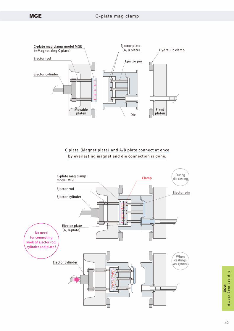
C-plate mag clamp model MGE(=Magnetizing C plate)
C-plate mag clampmodel MGE
Ejector plate(A, B plate)
Clamp
Ejector rod
Ejector cylinder
Movableplaten
Fixedplaten
No needfor connecting
work of ejector rod,cylinder and plate !
Ejector rod
Ejector cylinder
Ejector plate(A, B-plate)
Ejector cylinder
Ejector pin
Ejector pin
Hydraulic clamp
Die
Duringdie-casting
Whencastingsare ejected
MGE C-plate mag c lamp
C plate (Magnet plate) and A/B plate connect at once
by everlasting magnet and die connection is done.
C-plate mag clamp
MG
E
42

Ejector rod
Screw
Ejector cylinder
Ejector pin
Ejector plate
Die
Ejector rod
Ejector cylinder
Double nut
Ejector pin
Movableplaten
Die
①Ejector rod is screwed on plate, ②Die is fixed on platen and ③Ejector rod is mounted on cylinder from the back side in a conventional method. It wastes time to change a die.
The maintenance cost (repair, purchase for replacement and die repair)
is high and there is a risk of production stop.
Need to work at back side of machine and in a narrow space.
Need more time to mount.
Movableplaten
MGE C-plate mag c lamp
In case of manual t ightening connection rod …
C-plate mag clamp
MG
E
43

Hard to insert a connection boss when loading a die.(C plate and connection boss interfere with each other.)
When die galling occurs, pull back force causes a damage.
A-plateB-plateD-plate
Movableplaten
Connection boss
Ejector pin
DieC-plate
A-plateB-plate Die
Connectionboss
Ejector rod
Ejector pin
Movableplaten
Die galling
→Oil leakage occurs.
C-plateD-plateDamage
Damage
Damage
Damage
Connection boss is man-ufactured for each die andit costs too much. Storage space must be secured as well.
The maintenance cost (repair, purchase for replacement and die repair)
is high and there is a risk of production stop.
MGE C-plate mag c lamp
In case of hydraulic type automatic C plate of c lamp …
C-plate mag clamp
MG
E
44

Pascalmagclamp
Limit switch cable
Power cable
Terminalbox
Power voltage : 200V / 220V
・Different voltage is available.・Cables are not included.
Control box
Die-castingmachines
Power
C-plate mag clamp
Interlock cable
MGE C-plate mag c lamp
● The operation for clamp (connection) and unclamp (disconnection) are performed on operation panel of die-casting machine. Contact Pascal for the details.
System configuration
C-plate mag clamp
MG
E
45

Pascalmagclamp
Pascalmagclamp
Displacement detection core
Magnet coreSize:32×100mmQuantity:16Total clamping force: 59kN
・It detects that the ejector plate (A and B) is in close contact with magnet clamp when clamping.・It detects a displacement of ejector plate.
Mounting bracket
Self-standing type Hang down typeWall mount type
model EMGD-G
Con t ro l box
kg
Mod e l EMGD-G
Height400 × Width350 × Depth200 (mm)
Weight 25
Magne t p l a t e
model MGE
(Displacement detection system)
Close contact detection proximity switch
MGE C-plate mag c lamp
● Specifications of magnet plate differ depending on dies. Contact Pascal for the details.
C-plate mag clamp
MG
E
46
page → 48

NNS
NS
SN S
SN
SN
N S
NS
S N
SN
SNNeodymium magnet
Magnet core
Alnico magnet
Electromagnetic coil
Clamp plate
C l amp(Magne t i z ed) Unc l amp(Demagne t i z ed)
Effective height of magnetic flux : approx 20mm
Lines of magnetic flux
Ejector plate (A, B-plate)
Ejector pin
Electromagnetic coil is energized for 0.5 sec.
Polarity of alnico magnet is inverted.
Neodymium magnet and alnico magnet become homopolar.
Magnet core becomes a strong magnet to clamp the ejector plate.
1
2
3
4
1
2
3
Electromagnetic coil is energized for 0.5 sec.
Polarity of alnico magnet is inverted.
Magnetic flux of neodymium magnet and
Alnico magnet is not emitted from the sur-
face of the magnet core.
Thus, it unclamps the ejector plate.
Super strongpermanent magnet
Inverts the polarity by electromagnetic coil.
Inverts the polarityof alnico magnet.
Powerfully adheres die.
MGE C-plate mag c lamp
Structure and function
C-plate mag clamp
MG
E
47

NNS
NS
SN
NNS
NS
SN
① Displacement or lifting
② Flux changes due to displace- ment or lifting
③ Induction cur- rent is generated.
Close contact with ejector plate (A and B)
and magnet core.
Stable magnetic flux
Electromagnetic coil
Displacement detection core
Ejector plate
(A and B)
Displacement or lifting of die can be detected by the electromagnetic coils built into the magnet core near the center
of clamp plates. (When the ejector plate moves, these electromagnetic coils detect an induction current signal.)
Normal clamping status When the die moves
Displacement of ejector plate(A and B)
MGE C-plate mag c lamp
Displacement detection system(standard) PAT.
C-plate mag clamp
MG
E
48
365
325
290
310450
360
150
370
6
310
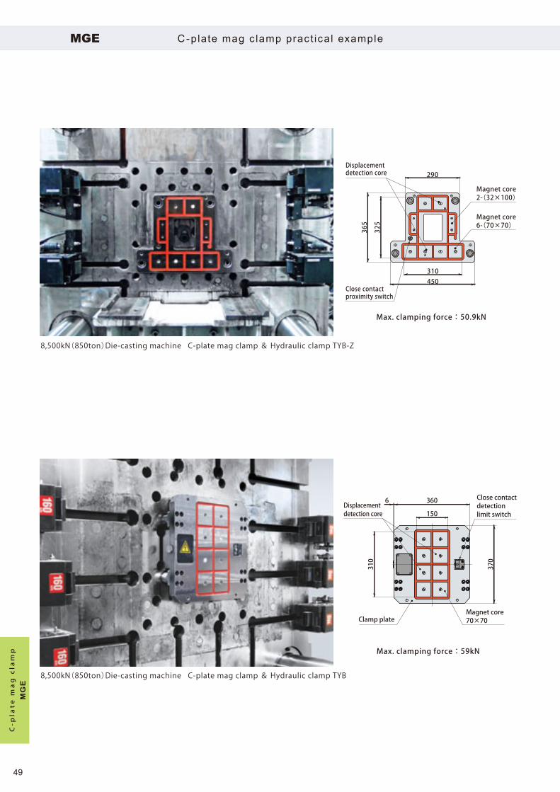
Max. clamping force:59kN
Max. clamping force:50.9kN
Magnet core70×70
Close contact detection limit switch
Displacement detection core
Clamp plate
8,500kN(850ton)Die-casting machine C-plate mag clamp & Hydraulic clamp TYB-Z
8,500kN(850ton)Die-casting machine C-plate mag clamp & Hydraulic clamp TYB
Magnet core6-(70×70)
Magnet core2-(32×100)
Displacement detection core
Close contactproximity switch
MGE C-plate mag c lamp pract ical example
C-plate mag clamp
MG
E
49

480
350
230
45
310
600
520
400
350
Max. clamping force:118kN (59kN×2)
Max. clamping force:61kN
Close contact detection limit switch
Displacement detection core
Displacementdetection core
Clamp plate
Clamp plate
Magnet core70×70
40,000kN(4,000ton)Die-casting machine C-plate mag clamp
16,500kN(1,650ton)Die-casting machine C-plate mag clamp
Magnet core4-(75×75)
Magnet core8-(50×50)
Close contact detection limit switch
MGE C-plate mag c lamp pract ical example
C-plate mag clamp
MG
E
50

Automatic connection of ejector rod
Ball lock coupler machine side
Steel ball
Adaptor
Ball lock coupler die side
Ball lock coupler
Connection and disconnection of ejector cylinder and plate (A and B) on die side can be automatic
by connecting and disconnecting the ejector rod with ball locking. Connection and disconnection is
available outside the machine by button operation and it shortens a set up time.
MED Bal l lock coupler
Ball lock coupler
ME
D
51

25MED P 25MED S
Machine side
Steel ball Hex. socketWidth across flatsAdaptor
(prepared by customer)
Machine side Die side
At disconnectionAir unlock
At connection
MED□P MED□S
M o d e l d e s i g n a t i o n
Rod diameter
:ø25mm25
:ø29mm29
:ø37mm37
Die side
Rod diameter
:ø25mm25
:ø29mm29
:ø37mm37
AirON
AirOFFSpring lock
(auto-locking)
MED Bal l lock coupler
● O-ring is included on machine side.(quantity:1, material:NBR)
Model MED25 MED29 MED37
Rod diameter mm ø25 ø29 ø37
Max. allowable load
When projected kN 25 40 63
When returned kN 4.0 6.3 10
Operational system
Lock Spring lock(automatic clamp)
Unlock Air unlock
Operating air pressure MPa 0.2 ~ 0.7
Operating temperature ℃ 0 ~ 70
WeightMachine side g 140 195 385
Die side g 85 135 260
Ball lo
ck coupler M
ED
52

MED□S
MED□P
MED□P
Ejectorcylinder
Ejector pin
Double nut
Die
Adaptor
Ejector plate
Movableplaten
Original position
Clearance
Secondoriginal position
When inclination amount of rodis large, provide a guide bush.
Initial state
Die loading
→ Adjusting die thickness
→ Clamping completion
Die opening
The ejector cylinder strokes
forward to the end*.
A f t e r s t r oke comp le t i on ,
turn off the air unlocking to
complete the connection.
The ejector cylinder retracts to
the second original position*
(position for die-casting).
* Determined in accordance
with die size.
1
2
3
4
5
Fixedplaten
Stroke (to the end)
MED Bal l lock coupler
Operational sequence
Ball lock coupler
ME
D
53

Ball lock couplerdie side
Ejector plate
Ejector plate
Ball lock couplerdie side
Ball lock couplermachine side
Adaptor
(Open / Close)
Lock / Unlockchangeover switch
Pilot air
* In case that interlock is required, contact Pascal.
Air 0.2~0.7MPa
Apply glue
MED Bal l lock coupler
Caution in use
● Applying glue (moderate strength) is recommended on die side. Recommended glue for screw lock :Loctite 243
● Make sure to use the adaptor which material has more strength than carbon steel for machine structural use (S45C etc.). In case of using a rolled steel for general structural use(SS400 etc.), adaptor may be worn, deformed and damaged due to strength deficiency.
Air c ircuit diagram
● When the air pressure is insufficient, unlocking may not be performed.
● Mount the ball lock couplers on machine side and die side with the tightening torque shown below. Excess and deficiency of tightening torque causes a malfunction.
Model MED25 MED29 MED37Tightening torque N·m 50 80 130
Ball lo
ck coupler M
ED
54

Auto coupler
Pascal has an extensive delivery records of automatic coupling system
in the plastic molding , die stamping and die-casting line .
Oil , Water , Air
1 ~ 35 MPa
3/8”, 1/2”, 3/4”, 1”, 1 1/4”, 1 1/2”, 2”
Max. working pressure
F l u i d
S i z e
Automatic
35,000kN(3,500ton)IMM Horizontal loading Auto coupler & Hydraulic clamp TKC
Auto coupler
60AMax. current
Electric connector
±5mm
Lock guide, self-alignment mechanism
Allowable eccentricity
Auto coupler
Auto coupler
55
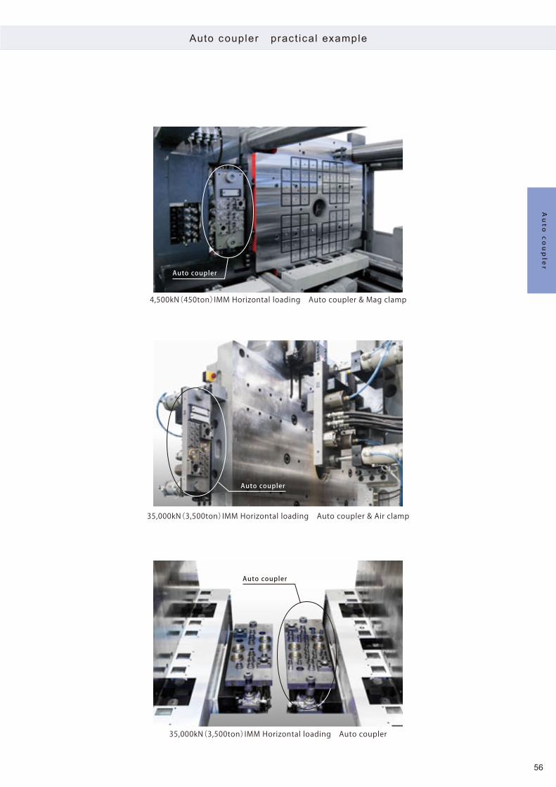
4,500kN(450ton)IMM Horizontal loading Auto coupler & Mag clamp
Auto coupler
Auto coupler
35,000kN(3,500ton)IMM Horizontal loading Auto coupler & Air clamp
35,000kN(3,500ton)IMM Horizontal loading Auto coupler
Auto coupler
Auto coupler pract ical example
Auto coupler
56

Die
Die sideMachine side
Oil 3/8″×4 ports
Electric connector
Water, AirRc1/2″×2 ports
Water, Air3/8″×2 ports
Lock guide socket
Oil 3/8″×4 ports
Electric connector
Water, AirRc1/2″×2 ports
Water, Air 3/8″×2 ports
Lock guide pin
Self-alignmentmechanism
Clamp TYB-Z
Bracket
T-slot
Auto coupler(machine side)
Auto coupler (die side)
Die
Auto coupler ver t ical loading conf igurat ion example
Fixed side
Auto coupler
57

Oil 3/8″×4 ports
Electric connector
Water, AirRc1/2″×2 ports
Lock guide socket
Oil 3/8″×4 ports
Electric connector
Die side Machine side
Water, AirRc1/2″×2 ports
Lock guide pin
Self-alignment mechanism
Water, Air3/8″×2 ports
Water, Air3/8″×2 ports
Clamp TYB-Z
T-slot
Bracket
Auto coupler(machine side)
Bracket
Auto coupler (die side)
Die
Auto coupler ver t ical loading conf igurat ion example
Movable s ide
Auto coupler
58

Die side
Machine sideWater, Air Rc1/2″×2 ports
Water, AirRc1/2″×2 ports
Water, Air3/8″×2 ports
Water, Air3/8″×2 ports
Lock guide socketOil 3/8″×4 ports
Oil 3/8″×4 ports
Electric connector
Electric connector
Lock guide pin
Self-alignmentmechanism
Bracket
Auto coupler(die side)
Auto coupler(machine side)
Clamp TYB-R
T-slot
Safety door
Stopper block MVA
Die changerPusher stand
Fixed platen
Roller blockmodel MHR
Centering cylinder MHP
Die roller MCR
Pusher head
Pusher latch
Die
Auto coupler hor izontal loading conf igurat ion example
Fixed side
Auto coupler
59

Die side
Machine side
Bracket
Auto coupler(die side)
Auto coupler(machine side)
Clamp TYB-R
T-slot
Safety door
Stopper block MVA
Die changerPusher stand
Hydraulic cylinder KC
Movable platen
Roller blockmodel MHR
Die roller MCR
Water, AirRc1/2″×2 ports
Water, AirRc1/2″×2 ports
Water, Air3/8″×2 ports
Water, Air3/8″×2 ports
Lock guide socketOil 3/8″×4 ports
Oil 3/8″×4 ports
Electric connector
Electric connector
Lock guide pin
Self-alignmentmechanism
Die
Auto coupler hor izontal loading conf igurat ion example
Movable s ide
Auto coupler
60

Easy and quick coupling
Multiple couplers are connectable easily and securely by pushing the gripper slightly.It prevents misplace of couplers and can shorten the coupling time.
Incorrect connectingprevention hole
Die (Plug) side Machine (Socket) side
Gripper
Lock guideIncorrect connectingprevention pin Lock guide socket
Coupler open model(Socket)
Coupler open model(Plug)Manual
18,000kN(1,800ton)IMM Multi coupler open model
Till 0 .8MPa
6 , 8 , 12
Water , Air , Oil
Pressu re
F l u i d
Number of ports
Rc1/4 , Rc3/8Pipe size
MCA Mult i coupler - open model
Multi coupler - open model
61

Fluid
Gripper
Machine side block
Lock guide pin
Lock guide socket
Coupler open type(Plug) Coupler open type
(Socket)
Mold side block
Lock ring
Incorrect connecting prevention pin
Incorrect connecting prevention hole
Piping connection port(Mold side)
Piping connection port(Supply side)
Mult i coupler - open modelMCA
Structure
Multi co
upler - o
pen model
62

Gripper
Indicator
Machine side coupler
Incorrect connectingprevention pin
Lock guideDie side coupler
Incorrectconnectingprevention hole
Mult i coupler - open model lock guide systemMCA
Lock ing ope ra t i on
Insert the couplers along the guide.
Push the gripper slightly and the locking has been completed.
Multi coupler - open model
63
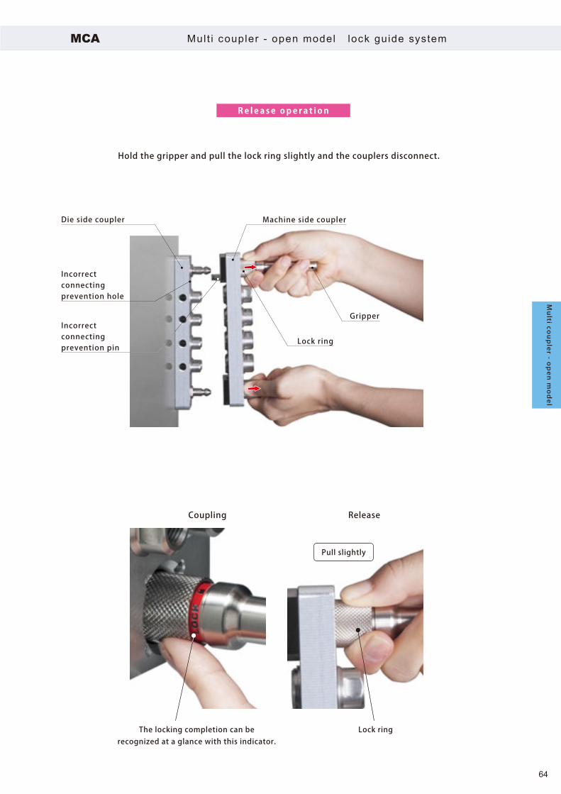
Lock ring
Gripper
Machine side couplerDie side coupler
The locking completion can berecognized at a glance with this indicator.
Coupling Release
Lock ring
Pull slightly
Incorrectconnectingprevention hole
Incorrectconnectingprevention pin
MCA
Re l ea se ope ra t i on
Mult i coupler - open model lock guide system
Hold the gripper and pull the lock ring slightly and the couplers disconnect.
Multi co
upler - o
pen model
64

MCA 02 P A 108
MCA 02 P A 112
4860
Rc1/4
200
225
13.5
13.5
2325
48
35
60
Rc1/4
148
173
35 25 23
Lock guide pin
4-ø6.8 holeSpot facing ø13 depth 8
(Back side)
Lock guide pin
4-ø6.8 holeSpot facing ø13 depth 8(Back side)
8 ports Mold side
12 ports Mold side
The mounting bolt on mold side is not included.
The mounting bolt on mold side is not included.
3×28 pitch
5×26 pitch
MCA02 Double row type Rc1/4
Multi coupler - open model
65
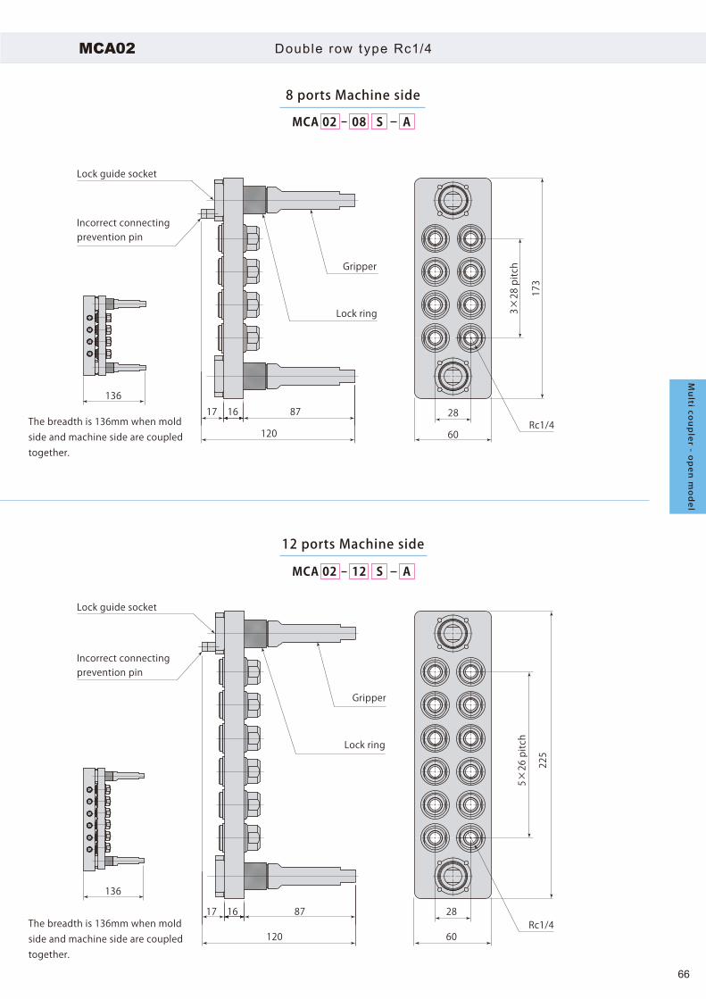
MCA 02 S A08
MCA 02 S A12
17 16 87
120
28
60
136
136
Rc1/4
173
17 16 87
120
28
60Rc1/4
225
Lock guide socket
Incorrect connecting prevention pin
Lock guide socket
Incorrect connecting prevention pin
Gripper
Lock ring
Gripper
Lock ring
8 ports Machine side
12 ports Machine side
3×28 pitch
5×26 pitch
The breadth is 136mm when mold side and machine side are coupled together.
The breadth is 136mm when mold side and machine side are coupled together.
MCA02 Double row type Rc1/4
Multi co
upler - o
pen model
66

35
Rc1/4
13.5
2325
48
285
35
233
218
13.5
2325
48
270
Rc1/4
MCA 02 P B 106
MCA 02 P B 108
6 ports Mold side
8 ports Mold side
5×26 pitch
Lock guide pin
2-ø6.8 holeSpot facing ø13 depth 8
(Back side)
The mounting bolt on mold side is not included.
The mounting bolt on mold side is not included.
Lock guide pin
2-ø6.8 holeSpot facing ø13 depth 8
(Back side)
7×26 pitch
MCA02 Single row type Rc1/4
Multi coupler - open model
67

17 16 87
120 35
223
Rc1/4
17 16 87
120
35
275
Rc1/4
136
136
MCA 02 S B06
MCA 02 S B08
6 ports Machine side
8 ports Machine side
Gripper
Lock ring
Gripper
Lock ring
5×26 pitch
7×26 pitch
Lock guide socket
Incorrect connecting prevention pin
Lock guide socket
Incorrect connecting prevention pin
The breadth is 136mm when mold side and machine side are coupled together.
The breadth is 136mm when mold side and machine side are coupled together.
MCA02 Single row type Rc1/4
Multi co
upler - o
pen model
68

180
155
235
210
162330
53
35
60
Rc3/8
Rc3/8
5360
1635 30 23
MCA 03 P A 108
MCA 03 P A 112
Lock guide pin
4-ø6.8 holeSpot facing ø13 depth 8
(Back side)
Lock guide pin
4-ø6.8 holeSpot facing ø13 depth 8(Back side)
8 ports Mold side
12 ports Mold side
The mounting bolt on mold side is not included.
The mounting bolt on mold side is not included.
3×28 pitch
5×28 pitch
MCA03 Double row type Rc3/8
Multi coupler - open model
69

180
155 18
0
235
210
235
162330
53
35
60
Rc3/8
Rc3/8
Rc3/8
Rc3/817 16 87
120
28
60
5360
1635 30 23
17 16 87
120
28
60
141
141
MCA 03 P A 108 MCA 03 S A08
MCA 03 P A 112 MCA 03 S A12
Lock guide pin
Lock guide socket
Incorrect connecting prevention pin
Lock guide socket
Incorrect connecting prevention pin
Gripper
Lock ring
Gripper
Lock ring
4-ø6.8 holeSpot facing ø13 depth 8
(Back side)
Lock guide pin
4-ø6.8 holeSpot facing ø13 depth 8
(Back side)
8 ports Mold side 8 ports Machine side
12 ports Mold side 12 ports Machine side
The mounting bolt on mold side is not included.
The mounting bolt on mold side is not included.
3×28
pitc
h5×
28 p
itch
3×28
pitc
h
5×28
pitc
h
The breadth is 141mm when mold side and machine side are coupled together.
The breadth is 141mm when mold side and machine side are coupled together.
MCA03 Double row type Rc3/8
Mu
lti cou
ple
r - op
en
mo
de
l
70

300
285
245
230
35
Rc3/8
16
2330
53
16
2330
5335
Rc3/8
MCA 03 P B 106
MCA 03 P B 108
6 ports Mold side
8 ports Mold side
5×28 pitch
Lock guide pin
2-ø6.8 holeSpot facing ø13 depth 8
(Back side)
The mounting bolt on mold side is not included.
The mounting bolt on mold side is not included.
Lock guide pin
2-ø6.8 holeSpot facing ø13 depth 8
(Back side)
7×28 pitch
MCA Double row type Rc3/8
Multi coupler - open model
71

290
235
17 16 87
120 35Rc3/8
17 16 87
120
35Rc3/8
141
141
MCA 03 S B06
MCA 03 S B08
6 ports Machine side
8 ports Machine side
Gripper
Lock ring
Gripper
Lock ring
5×28 pitch
7×28 pitch
Lock guide socket
Incorrect connecting prevention pin
Lock guide socket
Incorrect connecting prevention pin
The breadth is 141mm when mold side and machine side are coupled together.
The breadth is 141mm when mold side and machine side are coupled together.
MCA Double row type Rc3/8
Multi co
upler - o
pen model
72

MCA 03 08 P A 1 Mold plate
Mold (Body)
Mold side
Machine side
For Mold side ,1 is added in the end.
Row type A :Double row type B :Single row type
Connection port02 :Rc1/4 03 :Rc3/8
Number of port6ports, 8 ports, 12 ports
Machine side / Mold side S : Machine side P : Mold side
MCA Mult i coupler - open model
Model designation
Model MCA02 MCA03
Connection port Rc1/4 Rc3/8
Min. Passage area (per 1 port) mm2 57 86
Number of ports 6, 8, 12
Max. working pressure
At connection MPa 0.8
At disconnection Open
Body material
Coupler Stainless steel (Surface treatment: Electrolytic nickel plating)
Plate Aluminium alloy (Surface treatment: Electrolytic nickel plating)
Lock guide Carbon steel (Surface treatment: Electrolytic nickel plating)
Material of seal Nitrile rubber (NBR)
Fluid Water,Air ,General mineral based hydraulic oil
Operating temperature ℃ 0 ~ 70 (No freezing)
● Select the multi coupler check valve model MCB in case that the operating temperature is over 70℃ .● Both machine side and mold side have no check valve for preventing fluid leakage inside the coupler.
Connection port Number of port Machine/Mold side Mass kg Model Row type
Rc1/4
8 portsMachine side 1.1 MCA02 -08S -A
Double row typeMold side 0.8 MCA02 -08P -A1
12 portsMachine side 1.4 MCA02 -12S -AMold side 1.0 MCA02 -12P -A1
6 portsMachine side 0.9 MCA02 -06S -B
Single row typeMold side 0.6 MCA02 -06P -B1
8 portsMachine side 1.1 MCA02 -08S -BMold side 0.8 MCA02 -08P -B1
Rc3/8
8 portsMachine side 1.2 MCA03 -08S -A
Double row typeMold side 1.0 MCA03 -08P -A1
12 portsMachine side 1.5 MCA03 -12S -AMold side 1.3 MCA03 -12P -A1
6 portsMachine side 1.0 MCA03 -06S -B
Single row typeMold side 0.8 MCA03 -06P -B1
8 portsMachine side 1.1 MCA03 -08S -BMold side 1.0 MCA03 -08P -B1
Multi coupler - open model
73

20
ø25
Mold (Body)
Mold plateMagnet (4pcs)
Multi coupler
The multi coupler and mold can be installed by one touch operation
with powerful permanent magnet.
D imens i on s
* The double row type is applicable for mounting the magnet. The single row type can not be applied.
Mode l de s i gna t i on
MCA MG ADouble row type
Magnet (4pcs)
MCA02 Rc1/48 Ports :14812 Ports:200
MCA03 Rc3/88 Ports :15512 Ports:210
MCA Mult i coupler - open model Accessory Magnet mount ing
● Accessory is not included. Purcahse it seperately.
Connection port Number of port Magnet mounting model Row type
Rc1/4
8 portsMCA-MG-A Double row type
12 ports6 ports
― Single row type8 ports
Rc3/8
8 portsMCA-MG-A Double row type
12 ports6 ports
― Single row type8 ports
Multi co
upler - o
pen model
accessory
74

MCA 08 AH03
Coupler holder(Including the mounting bolt)
Plug
Mode l de s i gna t i on
Temporary holder for multi coupler
The plug is prvided to coupler holder and the fluid does not leak outside even when couplers are pressurized the machine side.
MCA Accessory Coupler holder (Inc luding the mount ing bol t)
● Accessory is not included. Purcahse it seperately.
Connection port Number of port Coupler holder model Row type
Rc1/4
8 ports MCA02 -08H-ADouble row type
12 ports MCA02 -12H-A6 ports MCA02 -06H-B
Single row type8 ports MCA02 -08H-B
Rc3/8
8 ports MCA03 -08H-ADouble row type
12 ports MCA03 -12H-A6 ports MCA03 -06H-B
Single row type8 ports MCA03 -08H-B
Multi coupler - open model
accessory
75

8 14456
M6
6025
230
10
6025
856144
285
10M6
285
104520
144856
M6
4520
340
10
144856
M6
10
271
4520
8
M6
14456
8
M6
14456
10
323
4520
6025
144856
10221
M6
144856
6025
10
273
M6
MCA02-08H-A MCA03-08H-A
MCA02-12H-A MCA03-12H-A
MCA02-06H-B MCA03-06H-B
MCA02-08H-B MCA03-08H-B
MCA Accessory Coupler holder (Inc luding the mount ing bolt)
Dimensions
Multi co
upler - o
pen model
accessory
76
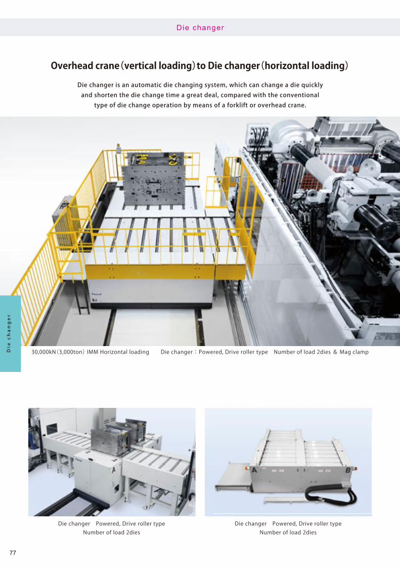
Overhead crane(vertical loading)to Die changer(horizontal loading)
30,000kN(3,000ton) IMM Horizontal loading Die changer : Powered, Drive roller type Number of load 2dies & Mag clamp
Die changer Powered, Drive roller typeNumber of load 2dies
Die changer Powered, Drive roller typeNumber of load 2dies
Die changer is an automatic die changing system, which can change a die quicklyand shorten the die change time a great deal, compared with the conventional
type of die change operation by means of a forklift or overhead crane.
Die changer
Die changer
77

Die changer Powered, Pusher mounted typeFixed roller table Number of load 1die
Die changer Manual loading, Rail typeNumber of load 2dies
Clamp TYB-R
T-slot
Safetydoor
Stopper block MVA
Die changerPusher stand
Pusher head
Pusher latch
Hydrauliccylinder KC
*For the installation of pusher, there are stand type(installed separately)and incorporated type in Die changer.
Movableplaten
Roller blockmodel MHR
Centering cylinder MHP
Die roller MCR
Die
Die changer conf igurat ion example
Die changer
78

ChangerPusher stand
Rail
Pusher latch
Pusher head
Fixed platenMovable platen
Die
Changer
Changer
Rail
Fixed platenMovable platen
Die
Fixed platenMovable platen
Die
Die changer layout example
Non track
Box framed rai l type
Short distance travel ing 2dies
Manual loading
Pusher
Manual loading
Die changer
79

Changer
Changer
Changer
Die
Rail
Rail
Rail
Drive roller
Roller
Roller table
Roller table
Fixed platenMovable platen
Die
Pusher latch
Pusher head
Pusher latch
Pusher head
Pusher(incorporated in die changer)
Fixed platenMovable platen
Die changer layout example
1 pitch travel ing 2dies Face to face layout
1 pitch travel ing 1die Pushing in/out style
Drive rol lers
Pusher
Die changer
80
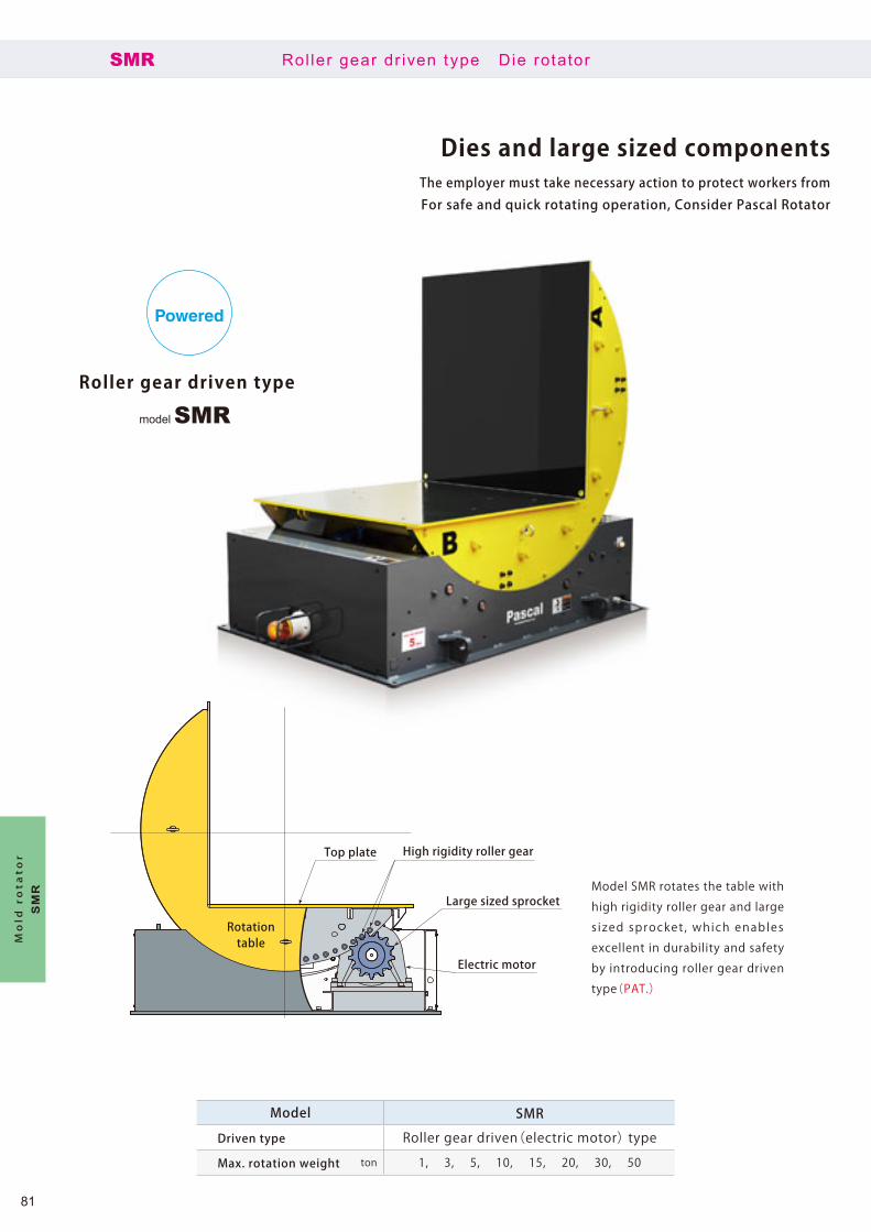
High rigidity roller gear
Rotationtable
Large sized sprocket
Top plate
Electric motor
Model SMR rotates the table with
high rigidity roller gear and large
s ized sprocket , which enables
excellent in durability and safety
by introducing roller gear driven
type(PAT.)
model SMRRoller gear driven type
Powered
SMR Rol ler gear dr iven type Die rotator
Dies and large sized components The employer must take necessary action to protect workers from
For safe and quick rotating operation, Consider Pascal Rotator
Model SMR
Driven type Roller gear driven(electric motor) type
Max. rotation weight ton 1, 3, 5, 10, 15, 20, 30, 50
Mold rotator
SM
R
81

model SMFFlat type
Powered Hydraulic
Model SMF is embeddable and
flat table.
The table is r igid enough to be
pas sed ove r by a f o r k l i f t o r a
truck.
SMF Flat type Die rotator
can be rotated safely and quickly.dangerous work in accordance with Industrial Safety and Heath Law.for the die and coil materials in place of overhead cranes.
Model SMF
Driven type Roller gear driven(electric motor) type Hydraulic cylinder driven type
Max. rotation weight ton 1, 3, 5 10, 15, 20, 30
Mold rotator
SM
F
82

Innovation of die-casting hydraulic cylinder
16,500kN(1,650ton)Die-casting machine 3 piece cylinder KC
3 piece cylinder KC
16,500kN(1,650ton)Die-casting machine3 piece cylinder KC
16,500kN(1,650ton)Die-casting machine3 piece cylinder KC
Innovative die-casting hydraulic cylinder with durability, excellent maintainabilityand compact size comparing to the conventional hydraulic cylinder.
3 piece cyl inder (core cyl inder)KC/KF
3 piece cylinder
KC/K
F
83

Cylinder S-type switchB-type switch
B-type switch
C-type switch
C-type switch
S-type switch
KCLKFL
KCBKFB
KCSKFS
KCCKFC
3 piece cyl inder (core cyl inder)KC/KF
● The Full bore cylinder model KF is selectable for ø50, ø63, ø80, ø100, ø125.*:B-type switch is not available for stroke 200mm.
Selection of 3 piece cyl inder
Cylinder inner diameter and stroke
Cylinder inner diameter and stroke
Cylinder inner diameter Strokeø 40 10 15 20 25 50 65 80 100 125 150 -
ø 50 10 15 20 25 50 65 80 100 125 150 -
ø 63 10 15 20 25 50 65 80 100 125 150 -
Cylinder inner diameter Strokeø 80 10 15 20 25 50 65 80 100 125 150 200*
ø 100 10 15 20 25 50 65 80 100 125 150 200*
ø 125 - - - - 50 65 80 100 125 150 200*
mm
mm
3 piece cylinder
KC/ K
F
84

Integrated structure of cap,cylinder and flange
Integrated structure of piston and rodSleeve
30% shorter in overall length and 30% lighter of mass(compared with standard type of cylinder)
Excellent durability and maintenance performance
3 piece cylinder
3 piece cyl inder (core cyl inder) standardKC
3 piece cylinder
KC
85

SKC S N L080 150
Limit switch
Cylinder inner diameter
Rod tip section
Packing seal
Stroke
Limit switch mounting position
Mo d e l d e s i g n a t i o n
1
3
4
5
6
2
3 piece cyl inder (core cyl inder) standardKC
● Fluid: General mineral based hydraulic oil(ISO-VG32 equivalent) Water glycol system working oil(set the temperature range as 0-70℃ when using water glycol hydraulic oil.)
*: The heatproof temperature is limited according to the spec-ification of limit switch.
Model KCMax. working pressure MPa 16
Proof pressure MPa 24
Operating temperature ℃ 0~ 70(5~ 120 for heat proof type *)
Cushion No
1 Limit switch
Code L B S C
Limit switch Without limit switch B-type switch S-type switch C-type switch
2 Cylinder inner diameter Code 040 050 063 080 100 125
Cylinder inner diameter (mm) ø40 ø50 ø63 ø80 ø100 ø125
3 Rod tip section Code S F M
Rod tip section Stepped(standard)
Femalethread
Malethread
4 Packing seal Code N V
Packing Material NBR(standard)Operating temperature:0~70℃
Fluorocarbon (thermal resistant specification)Operating temperature:5~120℃
5 Stroke Code 010 015 020 025 050 065 080 100 125 150 200
Stroke (mm) 10 15 20 25 50 65 80 100 125 150 200
6 Limit switch mounting position (S-type switch, C-type switch only) Code L R
Limit switch mounting position Left Right
3 piece cylinder
KC
86

Integrated structure of cap, cylinder and flange
Integrated structure of piston and rodSleeve
Pull out force 1.5 times (compared with standard type of cylinder)
3 piece Full bore cylinder
3 piece cyl inder (core cyl inder) Ful l boreKF
3 piece cylinder Full bore
KF
87

SKF S N L080 150
Limit switch
Cylinder inner diameter
Rod tip section
Packing seal
Stroke
Limit switch mounting position
Mo d e l d e s i g n a t i o n
1
3
4
5
6
2
3 piece cyl inder (core cyl inder) Ful l boreKF
● Fluid: General mineral based hydraulic oil(ISO-VG32 equivalent) Water glycol system working oil(Set the temperature range as 0-70℃ when using water glycol hydraulic oil.)
*: The heatproof temperature is limited according to the spec-ification of limit switch.
1 Limit switch
Code L B S C
Limit switch Without limit switch B-type switch S-type switch C-type switch
2 Cylinder inner diameterCode 050 063 080 100 125
Cylinder inner diameter (mm) ø50 ø63 ø80 ø100 ø125
3 Rod tip section Code S F M
Rod tip section Stepped(standard)
Femalethread
Malethread
4 Packing seal Code N V
Packing Material NBR(standard)Operating temperature:0~70℃
Fluorocarbon (thermal resistant specification)Operating temperature:5~120℃
5 Stroke Code 010 015 020 025 050 065 080 100 125 150 200
Stroke (mm) 10 15 20 25 50 65 80 100 125 150 200
6 Limit switch mounting position (S-type switch, C-type switch only) Code L R
Limit switch mounting position Left Right
Model KFMax. working pressure MPa 16
Proof pressure MPa 24
Operating temperature ℃ 0~ 70(5~ 120 for heat proof type *)
Cushion No
3 piece cylin
der Fu
ll bore
KF
88
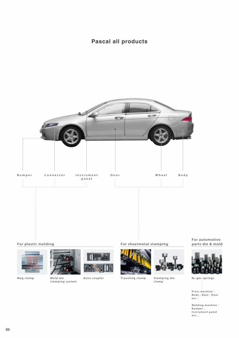
C o n n e c t o r I n s t r u m e n tp a n e l
B o d yB u m p e r W h e e lD o o r
Pascal all products
For automotiveparts die & moldFor sheetmetal stampingFor plastic molding
Mold d iec lamping system
Mag c lamp N2 gas spr ingsAuto coupler Trave l ing c lamp Stamping d iec lamp
Press machine : Body , Roof , Dooretc . . .
Mold ing machine : Bumper , Inst rument panel e tc . . .
89

E n g i n e T r a n s m i s s i o n A x l e
Pasca l products support
automot ive product ion l ines g lobal ly.
For die cast machine For metal cutt ing work
C-plate mag c lamp Die-c lampingsystem
Work c lamp Pal let c lamp Index tab le N2 gas ba lancer
90

JAPAN
DOMESTIC LOCATIONS
Sales office
Plant
Kumagaya, Saitama,
Atsugi, Kanagawa
Oita
Yamagata
Nagoya, Aichi
Osaka, Hyogo
Itami, HyogoHead office / R & D center
Head office / R & D center Oita plant Yamagata plant
Yamagata
Kumagaya
AtsugiNagoya
Head office(Itami, Hyogo)Oita
Yamagata
Hiroshima
Hiroshima
91

ASIA AMERICA
Dalian[China]
Shanghai[China]
Changchun[China]
Tianjin[China]
Wuhan[China]
Chongqing[China]
Guangzhou[China]
Taichung[Taiwan]
Deltamas[Indonesia]
Kuala Lumpur[Malaysia]
Mumbai[India]
Melbourne[Australia]
Bangkok[Thailand]
Changwon[Korea]
Chicago[U.S.A.]
Queretaro , León[Mexico]
Sao Paulo[Brazil]
EUROPE
Stuttgart[Germany]
Torino[Italy]
Paris[France]
Barcelona[Spain]
Bursa[Turkey]
GLOBAL NETWORK
Torino(Italy)Barcelona(Spain)
Dalian
Shanghai
Changwon(Korea)
ChangchunStuttgart(Germany)Bursa(Turkey)
Paris(France)
Melbourne(Australia)
Bangkok(Thailand)
Kuala Lumpur(Malaysia)
Deltamas(Indonesia)
Taichung(Taiwan)Mumbai
(India)
Chicago(U.S.A.)
Queretaro, León(Mexico)
Sao Paulo(Brazil)
ChongqingTianjin
Wuhan
Guangzhou
Liaison officeSales officeSubsidiaryPlant Agent
92

Die cast clamping system
QMC-12E-62019. 12
Specifications are subject to change without prior notice.
Itami, Hyogo, Japan 664-8502TEL. +81-72-777-3333 FAX. +81-72-777-3520
Chicago, U.S.A. TEL. +1-847-427-1234
Stuttgart, Germany TEL. +49-711-782-850-0
Dalian, China TEL. +86-411-8732-2988
Shanghai, China TEL. +86-21-5263-4122
Changwon, Korea TEL. +82-55-274-0971
Bangkok, Thailand TEL. +66-2173-5855
CERTIFICATE OF APPROVAL ISO9001