DICOM Enhanced XA/XRF Object New Dimensions for X-Ray ... · –the same Concatenation UID –the...
16
1 DICOM Enhanced XA/XRF Object DICOM Enhanced XA/XRF Object New Dimensions for New Dimensions for X X - - Ray Projection Imaging Ray Projection Imaging (DICOM Supplement 83) Authors : Heinz Blendinger Siemens Medical Solutions Bas Revet Philips Medical Systems (Editor supp83) Francisco Sureda GE Healthcare Rainer Thieme Siemens Medical Solutions (Chair DICOM WG-02) Speaker : Heinz Blendinger
Transcript of DICOM Enhanced XA/XRF Object New Dimensions for X-Ray ... · –the same Concatenation UID –the...
1
DICOM Enhanced XA/XRF Object DICOM Enhanced XA/XRF Object
New Dimensions for New Dimensions for
XX--Ray Projection ImagingRay Projection Imaging
(DICOM Supplement 83)
Authors:
Heinz Blendinger Siemens Medical Solutions
Bas Revet Philips Medical Systems (Editor supp83)
Francisco Sureda GE Healthcare
Rainer Thieme Siemens Medical Solutions (Chair DICOM WG-02)
Speaker:
Heinz Blendinger

2
Presentation outlinePresentation outline
•• OverviewOverview
–– Drivers and ConceptsDrivers and Concepts
•• Technical BenefitsTechnical Benefits
–– Encoding aspectsEncoding aspects
•• ScenariosScenarios
–– InteroperabilityInteroperability aspectsaspects
•• ConclusionsConclusions

3
WhyWhy a a newnew XA/XRF SOP XA/XRF SOP ClassClass ??
•• Shortcomings of actual XA SOPShortcomings of actual XA SOP--Class multiClass multi--frame frame
definition encouraged new workdefinition encouraged new work--itemitem
–– increasing number of attributes that change frameincreasing number of attributes that change frame--toto--frame require “frame require “per frameper frame” encoding mechanisms like ” encoding mechanisms like enhancedenhanced CT/MRCT/MR
–– the “4 GB boundary” per file can be reached, and require the “4 GB boundary” per file can be reached, and require mechanisms to allow mechanisms to allow splitting filessplitting files
–– new applicationsnew applications and technologies require new attributes and technologies require new attributes that shall be neither “private” nor “optional”that shall be neither “private” nor “optional”
–– new type of acquisition contexts require to encode other new type of acquisition contexts require to encode other dimensionsdimensions than “time”than “time”
4
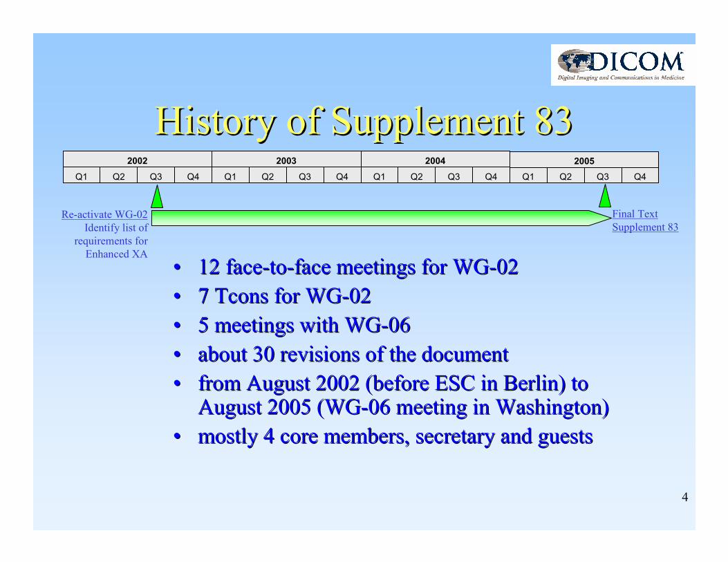
History of Supplement 83History of Supplement 83
•• 12 face12 face--toto--face meetings for WGface meetings for WG--0202
•• 7 Tcons for WG7 Tcons for WG--0202
•• 5 meetings with WG5 meetings with WG--0606
•• about 30 revisions of the documentabout 30 revisions of the document
•• from August 2002 (before ESC in Berlin) to from August 2002 (before ESC in Berlin) to August 2005 (WGAugust 2005 (WG--06 meeting in Washington)06 meeting in Washington)
•• mostly 4 core members, secretarymostly 4 core members, secretary and guestsand guests
Q1 Q2 Q3 Q4 Q1 Q2 Q3 Q4 Q1 Q2 Q3 Q4
2002 2003 2004
Q1 Q2 Q3 Q4
2005
Re-activate WG-02
Identify list of
requirements for
Enhanced XA
Final Text
Supplement 83

5
ConceptsConcepts of of Enhanced Enhanced XA/XRF SOP XA/XRF SOP ClassClass
• Full Acquisition context and Time Relationship per frame with Functional Group Macros
• File splitting through Concatenation mechanism
• Scalability from “Mobile C-Arm” to “Catheterization Lab”
• Support new applications with new attribute definitions– image presentation � Frame Pixel Properties, Multi-frame Presentation,
Improved Mask attributes
– image processing � Pixel Intensity Relationship LUT
– image calibration � Projection Pixel Calibration
– volume recon � Per frame Acquisition Context and Geometry
– image registration � Isocenter Reference System
– quality control � Sensing Regions, detailed Frame Acquisition info
• Dimension context information from Dimension Module

6
Per Frame encoding with Per Frame encoding with Functional Group MacrosFunctional Group Macros
• Frame Content: absolute Times
• Cardiac Trigger: exact reference to R-peak
• Frame VOI-LUT: individual windowing
• Frame Pixelshift: multiple individual values
• Patient Orientation: individual orientations
• Frame Display Shutter: individual positions
• Field of View: individual size
• Projection Pixel Calibration: individual magnification
• Frame Acquisition: individual context
• Collimator: individual blade movement
• Iso center Reference System: individual registration
O the r a ttr ib u te s
P e r -f ram e F un c tio n a l G ro u p s S eq ue n c e
S ha re d F u n c t io n a l G ro up s S e qu en ce
> F u n c tio n a l G ro u p A M a c ro
> F u n c t io n a l G ro up B M ac ro
> F u n c tio n a l G ro u p M M a c ro
… ..
O th e r a ttr ib u te s
F u n c tio n a l G ro u p M a c ro s
sh a red fo r a l l fr am e s
Item 1 (F ram e 1 )S eq u en c e o f re p e a tin g
F u n c t io n a l G ro u p M ac ro s fo r
e a c h in d iv id u a l fr am e
P ixe l D a ta
F ram e 1
F ram e 2
F ram e n
… ..
> F u n c t io n a l G ro u p C M a c ro
> F u n c t io n a l G ro up B M ac ro
> F u n c tio n a l G ro u p M M a c ro
… ..
Item n (F ram e n )
> F u n c t io n a l G ro u p C M a c ro
> F u n c t io n a l G ro up B M ac ro
> F u n c tio n a l G ro u p M M a c ro
Item 2 (F ram e 2 )
> F u n c t io n a l G ro u p C M a c ro
… ..
… ..
… ..
N o te : T h e F un c tio n a l G ro u p M a c ro s A , B , C , e tc . a re e xam p le s to illu s tra te th e M u lt i-f ram e F un c tio n a l G ro u p s . T h ea c tu a l F u n c t io n a l G ro u p S e q ue n c es a re d e fin e d e ls ew h e re .
… ..
> F u n c tio n a l G ro u p K M a c ro
Reuse of functional group solution
introduced with enhanced CT/MR
Optimized encoding of attributes that either change
in a per-frame basis or are shared for all the frames,
depending on the acquisition context
Examples in Enhanced XA

7
Splitting files with Splitting files with ConcatenationConcatenation mechanismmechanism
Reuse of concatenation solution
introduced with enhanced CT/MR
Ability to encode a single object (run acquisition) in
different SOP Instances
BENEFITS:
• optimized storage on disk
• allow to exchange big objects on CD-R
• override limitations of >4GB file size
Shared Header
Per frame Header
Dimension Data
Pixel Data
A AB C B C
A A B B C CMECHANISM:
• concatenation is a set of SOP Instances
• in the same SERIES
• with same fixed header and dimension indexes
• all SOP Instances of a concatenation have:– the same Concatenation UID
– the same Instance Number
SOP Instance A SOP Instance B SOP Instance C
8
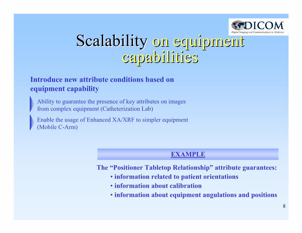
ScalabilityScalability on equipment on equipment capabilitiescapabilities
The “Positioner Tabletop Relationship” attribute guarantees:
• information related to patient orientations
• information about calibration
• information about equipment angulations and positions
Introduce new attribute conditions based on
equipment capability
Ability to guarantee the presence of key attributes on images
from complex equipment (Catheterization Lab)
Enable the usage of Enhanced XA/XRF to simpler equipment
(Mobile C-Arm)
EXAMPLE

9
Scenario:Scenario:Presentation of ImagesPresentation of Images
Application needs:
• Enhanced cine review: Group frames into ranges with individual settings:
• frame-rate
• display or skip flag
• Enhanced presentation of pixels: information about pixel pre-processing and
« desired » presentation settings:
• filter percentage value
• advanced Mask module attributes for multi-mask DSA processing
• enable adaptive processing based on provided pre-processing information
attributes
• now permitting MONOCHROME1 & 2
Enhanced cine review and pixel
presentation capabilities

10
Scenario: create unprocessed Scenario: create unprocessed pixels for further processingpixels for further processing
• A basic pixel “format” of LINEAR or LOGARITHMIC pixel intensity relationship may be needed prior to other specific processing steps (densitometry, edge detection, presentation LUTs…).
• The new Pixel Intensity LUT mechanism provides means to identify and apply LUT that deliver the intended result – “TO_LIN” or “TO_LOG” or even more…
Application needs:
Ability to get back to a known (reference)
X-ray-to-pixel intensity relationship, to
enable post-processing applications
Stored
Values
VOI
LUT
P
LUTDisplay
Pixel Intensity
Relationship
LUT
Pixel values transformed
for specific application (if
TO_LINEAR, then pixel
values proportional to the
X-ray beam intensity)Pixel Intensity
Relationship LUT
Sequence (0028,x422)
Application
Modality
LUT
Pixel Intensity
Relationship
LUT
Pixel values transformed
for specific application
Pixel Intensity
Relationship LUT
Sequence (0028,x422)
1 to N
Application

11
Scenario: Scenario: Projection Pixel CalibrationProjection Pixel Calibration
• Requires “Positioner Tabletop Relationship” attribute:
– C-arm based equipment with system-provided angulations and distances
– Equipment with system-provided Table Height and Beam Angle
• Requires a real-world value of distance from interested object plane to table top
– To be provided by user or as system default.
Application needs:
Ability to calculate the
projected pixel size of objects
of interest placed at a given
distance from the table top
Table TO
X-R ay
Source
Isocenter
TH
ISO
SID
Beam Angle
#Px
D
D = # Px * ∆ Px * SOD / SID
SOD = ISO - (TH-TO) / cos°(Beam Angle)
D: Distance in Object
#Px: Number Pixels
∆Px: Imager Pixel Spacing
ISO: Source Isocenter Distance
SID: Source Image Receptor Distance
SOD: Source Object Distance
TH: Table Height
TO: Distance Object Table Top

12
Scenario: Scenario: Rotational Rotational DSA with DSA with bibi--directional acquisitiondirectional acquisition
Frame #3:
mask 4
Frame #4:
mask 3
Frame #5:
mask 2Frame #6:
mask 1
Frame #12:
contrast 4
Frame #11:
contrast 3
Frame #10:
contrast 2Frame #9:
contrast 1
Run 1 Step 2
#1 - #2
Run 1 Step 1
Application needs:
Easily encode the association
of the mask-contrast frames
on bi-directional acquisitions
#3 - #6
mask 4,3,2,1#7 - #8
#9 - #12
contrast 1,2,3,4
• Improved Mask Module:
Reverse TID mask operation
allows to define the mask-
contrast associations of a bi-
directional acquisition REV_TID offset
#13 - #15
Preceding frames
Mask frames Gap frames
Trailing frames
Contrast frames
Mask-Contrast associations

13
Scenario: Scenario: Volume reconstruction supportVolume reconstruction support
• X-Ray generation parameters (mA, kVp…) on frame level to allow intensity corrections
• Geometry properties (SID, ISO) on frame level to allow dynamic changes during run.
• Isocenter Projection for detectors to align projected image to isocenter reference point
Application needs:
Knowledge of per-frame specific information
(X-ray generation, detection and geometry) to
optimize the 3D reconstruction algorithms
Frame #1:X-ray settings 1
Geometry settings 1
Optimized 3D
Reconstruction
Frame #2:X-ray settings 2
Geometry settings 2
Frame #3:X-ray settings 3
Geometry settings 3
Frame #4:X-ray settings 4
Geometry settings 4

14
Scenario: Scenario: Use of Use of Isocenter Isocenter Reference SystemReference System
Application needs:
Register images/frames of different
acquisition runs for 3D reconstruction
or blending/sewing of images
• Requires “Positioner Tabletop Relationship” attribute
– C-arm based equipment with system-provided angulations and distances
– Reference from image plane to equipment space (Isocenter based coordinates)
+Y
+Z +XO
+Y
+Z +XO
Run #1:
Rotational 3D
+Y
+Z +XO
Run #2:
Projection 2D3D-2D registration

15
Conclusions and Next Steps Conclusions and Next Steps
•• Supplement 83 enhances interoperability and Supplement 83 enhances interoperability and
overcomes the known limitations of the current overcomes the known limitations of the current
XA SOP Class XA SOP Class
•• It is open for today’s and new applications / It is open for today’s and new applications /
equipments equipments
•• DICOM WGDICOM WG--02 plans to disclose a technical 02 plans to disclose a technical
document with practical scenarios on Enhanced document with practical scenarios on Enhanced
XA usageXA usage
16
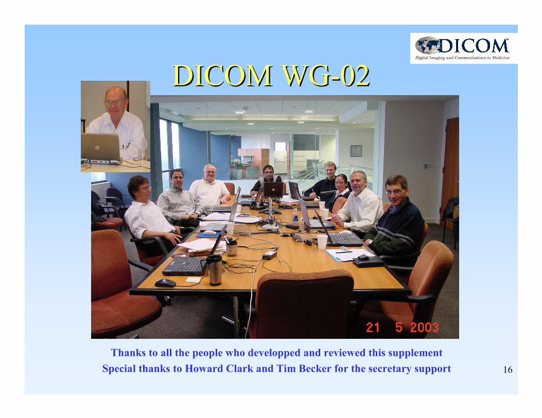
DICOM WGDICOM WG--02 02
Thanks to all the people who developped and reviewed this supplement
Special thanks to Howard Clark and Tim Becker for the secretary support
![S4Net: Single stage salient-instance segmentation · rather than instance segments. 2.3 Semantic instance segmentation Earlier semantic instance segmentation methods [22–24, 54]](https://static.fdocuments.in/doc/165x107/5fa63c2f83ae5a0cdb44c66e/s4net-single-stage-salient-instance-segmentation-rather-than-instance-segments.jpg)