
DICOM Conformance Statement Radiotherapy - Brainlab · DICOM Conformance Statement ... Multiple...
72
DICOM Conformance Statement RT Elements Document Revision 3 January 19, 2017 2017 © Copyright Brainlab AG
-
Upload
nguyenhanh -
Category
Documents
-
view
235 -
download
0
Transcript of DICOM Conformance Statement Radiotherapy - Brainlab · DICOM Conformance Statement ... Multiple...
DICOM Conformance Statement
RT Elements
Document Revision 3
January 19, 2017
2017 © Copyright Brainlab AG

DICOM Conformance Statement RT Elements
January 19, 2017 Document Revision 3 Page 3 of 72
1 Conformance Statement Overview
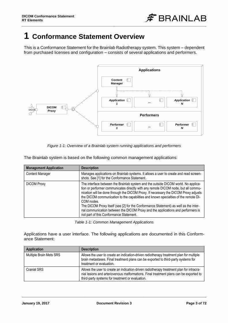
This is a Conformance Statement for the Brainlab Radiotherapy system. This system – dependent from purchased licenses and configuration – consists of several applications and performers.
Content
Manager
DICOM
Proxy
Application
1...
Performer
1...
DICOM
Applications
Performers
Performer
N
Application
N
Figure 1-1: Overview of a Brainlab system running applications and performers
The Brainlab system is based on the following common management applications:
Management Application Description
Content Manager Manages applications on Brainlab systems. It allows a user to create and read screen-shots. See [1] for the Conformance Statement.
DICOM Proxy The interface between the Brainlab system and the outside DICOM world. No applica-tion or performer communicates directly with any remote DICOM node, but all commu-nication will be done through the DICOM Proxy. If necessary the DICOM Proxy adjusts the DICOM communication to the capabilities and known specialties of the remote DI-COM nodes. The DICOM Proxy itself (see [2] for the Conformance Statement) as well as the inter-nal communication between the DICOM Proxy and the applications and performers is not part of this Conformance Statement.
Table 1-1: Common Management Applications
Applications have a user interface. The following applications are documented in this Conform-ance Statement:
Application Description
Multiple Brain Mets SRS Allows the user to create an indication-driven radiotherapy treatment plan for multiple brain metastases. Final treatment plans can be exported to third-party systems for treatment or evaluation.
Cranial SRS Allows the user to create an indication-driven radiotherapy treatment plan for intracra-nial lesions and arteriovenous malformations. Final treatment plans can be exported to third-party systems for treatment or evaluation.
DICOM Conformance Statement
RT Elements
Page 4 of 72 Document Revision 3 January 19, 2017
Application Description
Spine SRS Reads images and segmentations and allows to create an indication-driven radiother-apy treatment plan for spinal metastases. Final treatment plans can be exported to third-party systems for treatment or evaluation.
RT QA Allows the user to perform steps required for quality assurance of radiotherapy treat-ment plans.
Dose Review Enables the user to review therapeutic volume dose based on image and structure in-formation.
Adaptive Hybrid Surgery Analysis (AHSA)
Reads images, segmentations and registrations and allows the user to evaluate intra-operative data.
Table 1-2: Applications
Performers don’t have a user interface and perform their tasks in the background. The following performers are documented in this Conformance Statement:
Performer Description
DICOM RT Export Conversion of 3D objects and registration (fusion) data to DICOM RT compliant for-mat.
Table 1-3: Performers
The following additional applications and performers are included in the Radiotherapy system but will not be documented here. See [1] for the Conformance Statement.
Application Description
Patient Selection Allows the user to browse, load or save data in/to DICOM archives or on/to media (e.g., CD-ROM).
Image Viewer Allows the user to display any kind of DICOM image data.
Fusion Allows the user to overlap two different DICOM data sets.
Smartbrush Allows the user to create, read and update segmentations based on DICOM image data.
Object Manager Allows the user to create, review and modify segmentation objects based on the Uni-versal Atlas. Provides functionality to combine, subtract or intersect existing objects and to store the result as a new segmentation object.
Angio Planning Allows the user to register 3D CT/MR image data with segmented vessels to a 2D X-Ray Angio image data and then to segment a nidus in the 3D volume.
Fibertracking Allows the user to create, review and modify fiber bundles as surface segmentation objects. Allows to create simple manual ROIs as segmentation objects.
Performer Description
Auto Segmentation Performs segmentation tasks in the background
Universal Atlas Performer Performs deformable spatial registrations of datasets to the Brainlab Universal Atlas.
DICOM Conformance Statement RT Elements
January 19, 2017 Document Revision 3 Page 5 of 72
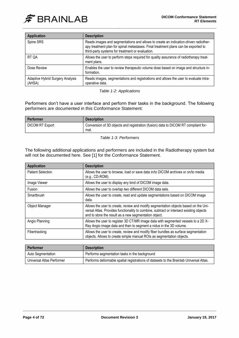
The table below addresses all supported network services used by the different radiotherapy ap-plication entities. For other applications, refer to [1]. For the SOP Classes in the Transfer section SCU and SCP have special meanings. Entities consuming data (e.g., for displaying images) are marked as SCP. Applications producing data (e.g., like spatial registrations) are marked as SCU. All created data will be initially stored to the DICOM Proxy, which then is responsible to forward created data to configured remote DICOM nodes.
Symbol: Meaning:
User of Service (SCU)
Provider of Service (SCP)
Both (SCU/SCP)
SOP Classes Mu
ltip
le B
rain
Met
s S
RS
Cra
nia
l SR
S
Sp
ine
SR
S
Do
se R
evie
w
RT
-QA
AH
SA
DIC
OM
RT
Exp
ort
Per
form
er
Transfer
CT Image Storage
Grayscale Softcopy Presentation State Storage
Key Object Selection Document Storage
MR Image Storage
Raw Data Storage
RT Dose Storage
RT Plan Storage
RT Structure Set Storage
Segmentation Storage
Spatial Registration Storage
Query/Retrieve
Study Root Query/Retrieve Information Model - FIND
Table 1-4: Supported network services
DICOM Conformance Statement
RT Elements
Page 6 of 72 Document Revision 3 January 19, 2017
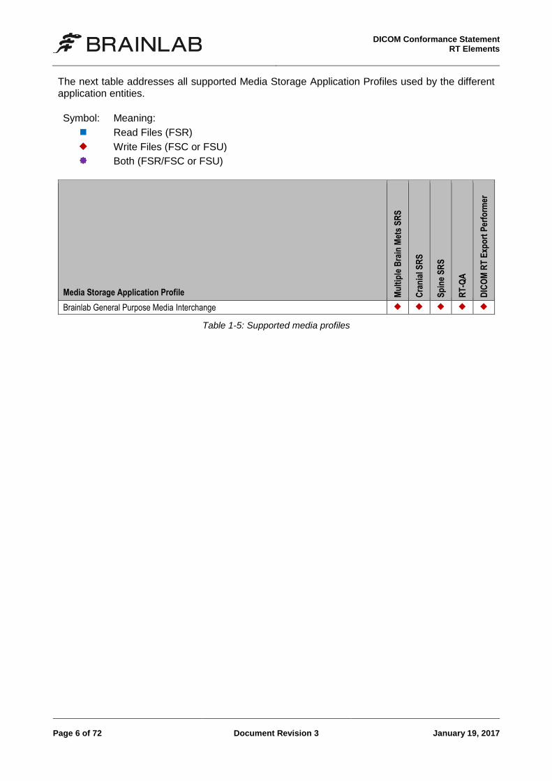
The next table addresses all supported Media Storage Application Profiles used by the different application entities.
Symbol: Meaning:
Read Files (FSR)
Write Files (FSC or FSU)
Both (FSR/FSC or FSU)
Media Storage Application Profile Mu
ltip
le B
rain
Met
s S
RS
Cra
nia
l SR
S
Sp
ine
SR
S
RT
-QA
DIC
OM
RT
Exp
ort
Per
form
er
Brainlab General Purpose Media Interchange
Table 1-5: Supported media profiles
DICOM Conformance Statement RT Elements
January 19, 2017 Document Revision 3 Page 7 of 72
2 Table of Contents
1 Conformance Statement Overview ___________________________________________ 3
2 Table of Contents _________________________________________________________ 7
3 Introduction ______________________________________________________________ 9
3.1 Revision History........................................................................................................... 9 3.2 Audience ..................................................................................................................... 9 3.3 Remarks ...................................................................................................................... 9 3.4 Abbreviations ............................................................................................................. 10 3.5 References ................................................................................................................ 10
4 Networking _____________________________________________________________ 11
4.1 Implementation Model ............................................................................................... 11 4.1.1 Application Data Flow Diagram ........................................................................ 11 4.1.2 Functional Definition of Application Entity (AE) ................................................. 12 4.1.3 Sequencing Of Real World Activities ................................................................ 14
4.2 Application Entity Specifications ................................................................................ 16 4.2.1 Common Specifications .................................................................................... 16 4.2.2 Multiple Brain Mets SRS Application Specification ........................................... 23 4.2.3 Cranial SRS Application Specification .............................................................. 25 4.2.4 Spine SRS Application Specification ................................................................ 27 4.2.5 Dose Review Application Specification ............................................................. 29 4.2.6 Adaptive Hybrid Surgery Analysis (AHSA) Application Specification ................ 31 4.2.7 RT QA Application Specification ....................................................................... 33 4.2.8 DICOM RT Export Performer Specification ....................................................... 35
4.3 Network Interfaces ..................................................................................................... 37 4.3.1 Physical Network Interface ............................................................................... 37 4.3.2 Additional Protocols .......................................................................................... 37
5 Media Interchange _______________________________________________________ 39
5.1 Implementation Model ............................................................................................... 39 5.1.1 Application Data Flow Diagram ........................................................................ 39 5.1.2 Functional Definitions of AE’s ........................................................................... 39 5.1.3 Sequencing of Real-World Activities ................................................................. 39 5.1.4 File Meta Information Options ........................................................................... 39
5.2 AE Specifications ....................................................................................................... 40 5.2.1 Common Export Specifications ......................................................................... 40
5.3 Augmented and Private Application Profiles .............................................................. 41 5.3.1 Augmented Application Profiles ........................................................................ 41 5.3.2 Private Application Profiles ............................................................................... 41
6 Support of Character Sets _________________________________________________ 43
7 Security Profiles _________________________________________________________ 45
7.1 Security Profiles......................................................................................................... 45 7.2 Association Level Security ......................................................................................... 45 7.3 Application Level Security .......................................................................................... 45
8 Annexes ________________________________________________________________ 47
8.1 IOD Contents ............................................................................................................. 47 8.1.1 Supported SOP Instances ................................................................................ 47
DICOM Conformance Statement
RT Elements
Page 8 of 72 Document Revision 3 January 19, 2017
8.1.2 Supported Modules .......................................................................................... 49 8.1.3 Usage of Attributes from Received IODs .......................................................... 62 8.1.4 Attribute Mapping ............................................................................................. 64 8.1.5 Coerced/Modified fields .................................................................................... 64
8.2 Data Dictionary of Private Attributes .......................................................................... 65 8.2.1 Group 0009 ...................................................................................................... 65 8.2.2 Group 3243 ...................................................................................................... 65 8.2.3 Group 3249 ...................................................................................................... 65 8.2.4 Group 3253 ...................................................................................................... 65
8.3 Coded Terminology and Templates ........................................................................... 66 8.4 Grayscale Image Consistency ................................................................................... 67 8.5 Standard Extended/Specialized/Private SOP Classes ............................................... 68 8.6 Private Transfer Syntaxes ......................................................................................... 69
9 Indexes ________________________________________________________________ 71
9.1 Index of Tables .......................................................................................................... 71 9.2 Index of Figures ......................................................................................................... 72
DICOM Conformance Statement RT Elements
January 19, 2017 Document Revision 3 Page 9 of 72
3 Introduction
3.1 Revision History
Document Revision
Date of Issue Author Description
3.2 Audience
This document is intended for hospital staff, health system integrators, software designers or im-plementers. It is assumed that the reader has a working understanding of DICOM.
3.3 Remarks
DICOM, by itself, does not guarantee interoperability. However, the Conformance Statement fa-cilitates a first-level validation for interoperability between different applications supporting the same DICOM functionality. The Conformance Statement should be read and understood in con-junction with the DICOM Standard [3]. However, by itself it is not guaranteed to ensure the desired interoperability and a successful interconnectivity. The user should be aware of the following important issues:
The comparison of different Conformance Statements is the first step towards assessing in-terconnectivity between Brainlab and non–Brainlab equipment.
This Conformance Statement is not intended to replace validation with other DICOM equip-ment to ensure proper exchange of information intended.
The DICOM standard will evolve to meet the users’ future requirements. Brainlab reserves the right to make changes to its products or to discontinue its delivery.
DICOM Conformance Statement
RT Elements
Page 10 of 72 Document Revision 3 January 19, 2017
3.4 Abbreviations
There are a variety of terms and abbreviations used in the document that are defined in the DICOM Standard. Abbreviations and terms are as follows:
AE DICOM Application Entity
AET Application Entity Title
CD Compact Disk
CD-R Compact Disk Recordable
DVD Digital Versatile Disc
FSC File-Set Creator
FSU File-Set Updater
FSR File-Set Reader
HD Hard Disk
IOD (DICOM) Information Object Definition
ISO International Standard Organization
MOD Magneto Optical Disk
PDU DICOM Protocol Data Unit
Q/R Query and Retrieve
RT Radiotherapy
SCU DICOM Service Class User (DICOM client)
SCP DICOM Service Class Provider (DICOM server)
SOP DICOM Service-Object Pair
3.5 References
[1] Brainlab AG, DICOM Conformance Statement Surgery 6.0, Feldkirchen: Brainlab AG, 2016.
[2] Brainlab AG, DICOM Conformance Statement DICOM Proxy 3.4, Feldkirchen: Brainlab AG, 2016.
[3] Digital Imaging and Communications in Medicine (DICOM) 3.0, Rev. 2016d, vol. PS 3, NEMA, 2016.
[4] Varian, Varian System Server 13 DICOM Conformance Statement, Varian, 2014.
[5] IHE, IHE RO Technical Framework: Multimodality Image Registration for Radiation Oncology, IHE, 2012.
DICOM Conformance Statement RT Elements
January 19, 2017 Document Revision 3 Page 11 of 72
4 Networking
4.1 Implementation Model
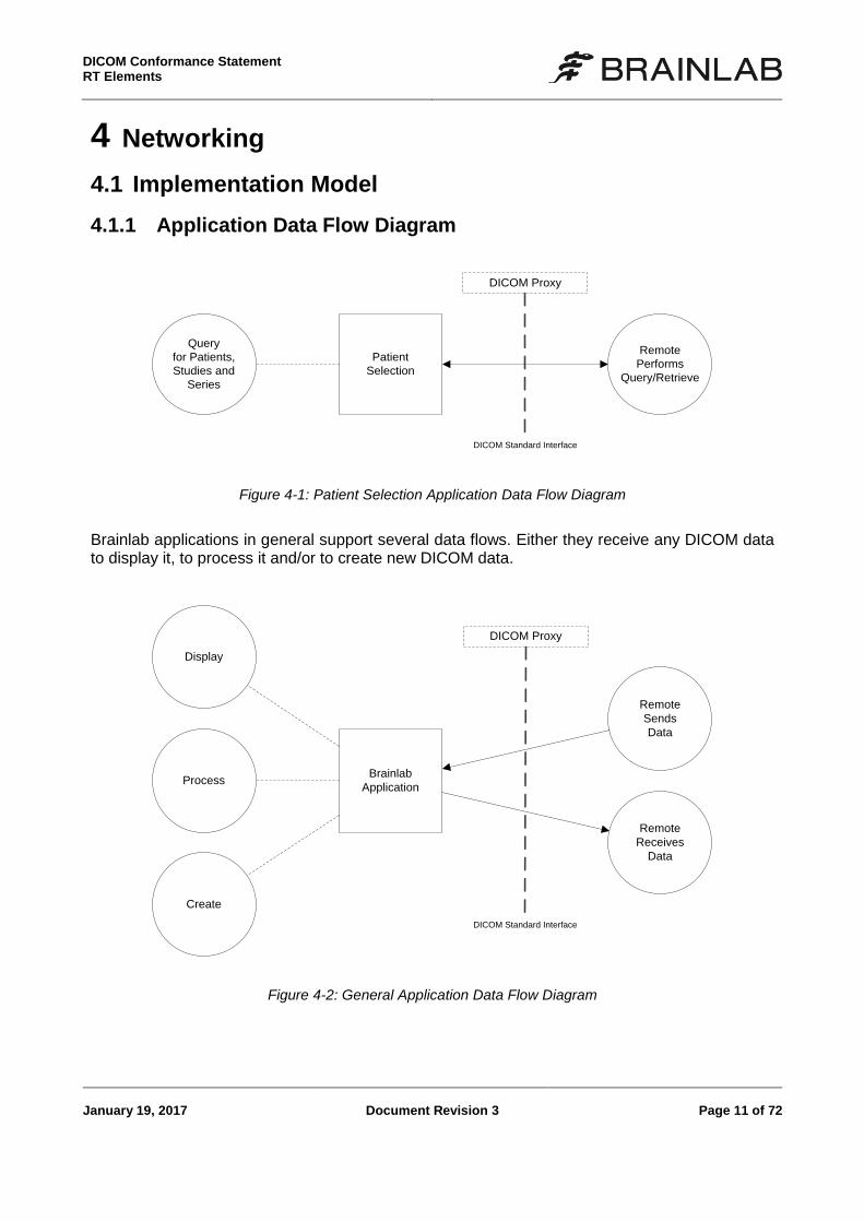
4.1.1 Application Data Flow Diagram
Patient
Selection
Query
for Patients,
Studies and
Series
Remote
Performs
Query/Retrieve
DICOM Standard Interface
DICOM Proxy
Figure 4-1: Patient Selection Application Data Flow Diagram
Brainlab applications in general support several data flows. Either they receive any DICOM data to display it, to process it and/or to create new DICOM data.
Brainlab
Application
Display
Remote
Sends
Data
Remote
Receives
Data
Create
DICOM Standard Interface
DICOM Proxy
Process
Figure 4-2: General Application Data Flow Diagram
DICOM Conformance Statement
RT Elements
Page 12 of 72 Document Revision 3 January 19, 2017
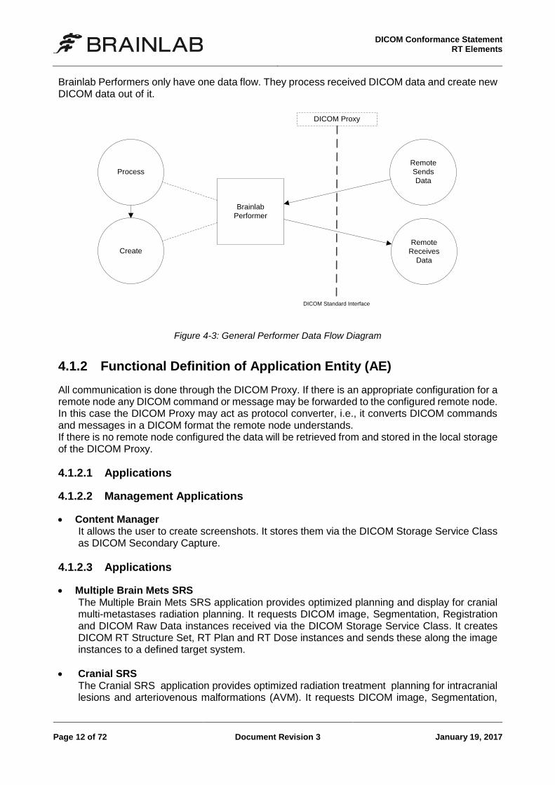
Brainlab Performers only have one data flow. They process received DICOM data and create new DICOM data out of it.
Brainlab
Performer
Process
Remote
Sends
Data
Create
DICOM Standard Interface
DICOM Proxy
Remote
Receives
Data
Figure 4-3: General Performer Data Flow Diagram
4.1.2 Functional Definition of Application Entity (AE)
All communication is done through the DICOM Proxy. If there is an appropriate configuration for a remote node any DICOM command or message may be forwarded to the configured remote node. In this case the DICOM Proxy may act as protocol converter, i.e., it converts DICOM commands and messages in a DICOM format the remote node understands. If there is no remote node configured the data will be retrieved from and stored in the local storage of the DICOM Proxy.
4.1.2.1 Applications
4.1.2.2 Management Applications
Content Manager It allows the user to create screenshots. It stores them via the DICOM Storage Service Class as DICOM Secondary Capture.
4.1.2.3 Applications
Multiple Brain Mets SRS The Multiple Brain Mets SRS application provides optimized planning and display for cranial multi-metastases radiation planning. It requests DICOM image, Segmentation, Registration and DICOM Raw Data instances received via the DICOM Storage Service Class. It creates DICOM RT Structure Set, RT Plan and RT Dose instances and sends these along the image instances to a defined target system.
Cranial SRS The Cranial SRS application provides optimized radiation treatment planning for intracranial lesions and arteriovenous malformations (AVM). It requests DICOM image, Segmentation,
DICOM Conformance Statement RT Elements
January 19, 2017 Document Revision 3 Page 13 of 72
and Registration and DICOM Raw Data instances received via the DICOM Storage Service Class. It creates DICOM RT Structure Set, RT Plan and RT Dose instances and sends these along the image instances to a defined target system.
Spine SRS The Spine SRS application provides optimized radiation treatment planning for spinal metas-tases. It requests DICOM image, Segmentation, and Registration and DICOM Raw Data instances received via the DICOM Storage Service Class. It creates DICOM RT Structure Set, RT Plan and RT Dose instances and sends these along the image instances to a defined target system.
RT QA The RT QA application provides means for verification of beam models as well as patient specific quality assurance. It requests DICOM image, Segmentation, Registration and Raw Data instances from the DICOM Proxy. It creates DICOM RT Structure Set, RT Plan and RT Dose instances and sends these along the image instances to a defined target system.
Dose Review The Dose Review application contains features for review of isodose lines, review of DVHs, dose comparison and summation. It requests DICOM image, Registration, RT Structure Set, RT Plan and RT Dose instances received via the DICOM Storage Service Class. It does not create any new DICOM instances.
Adaptive Hybrid Surgery Analysis The Adaptive Hybrid Surgery Analysis application simulates an automated template-based radiation treatment plan based on DICOM image, Segmentation and Registration instances received via the DICOM Storage Service Class.
For the following Applications, refer to [1]:
Patient Selection
Image Viewer
Fusion
Smartbrush
Object Manager
Angio Planning
Fibertracking
4.1.2.4 Performer
DICOM RT Export Background service to export DICOM RT Structure Sets for contouring workflows.
For the following Performers, refer to [1]:
Auto Segmentation
Vessel Segmentation
Universal Atlas
DICOM Conformance Statement
RT Elements
Page 14 of 72 Document Revision 3 January 19, 2017
4.1.3 Sequencing Of Real World Activities
4.1.3.1 Standard Interactive Use Case
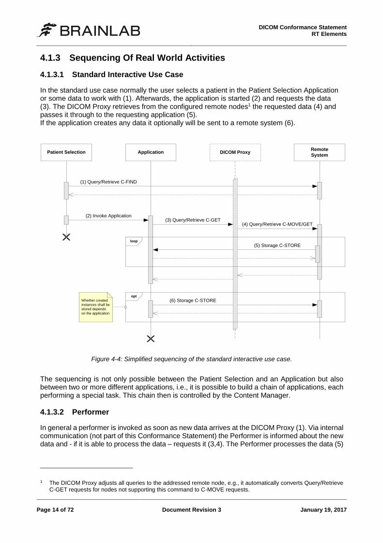
In the standard use case normally the user selects a patient in the Patient Selection Application or some data to work with (1). Afterwards, the application is started (2) and requests the data (3). The DICOM Proxy retrieves from the configured remote nodes1 the requested data (4) and passes it through to the requesting application (5). If the application creates any data it optionally will be sent to a remote system (6).
ApplicationRemote
SystemDICOM ProxyPatient Selection
(1) Query/Retrieve C-FIND
(2) Invoke Application
(4) Query/Retrieve C-MOVE/GET
(5) Storage C-STORE
(6) Storage C-STORE
loop
opt
Whether created
instances shall be
stored depends
on the application
(3) Query/Retrieve C-GET
Figure 4-4: Simplified sequencing of the standard interactive use case.
The sequencing is not only possible between the Patient Selection and an Application but also between two or more different applications, i.e., it is possible to build a chain of applications, each performing a special task. This chain then is controlled by the Content Manager.
4.1.3.2 Performer
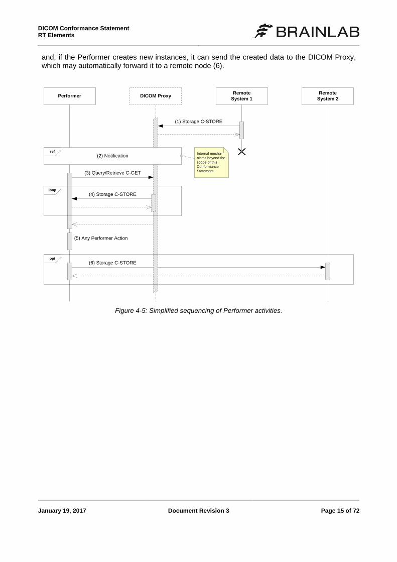
In general a performer is invoked as soon as new data arrives at the DICOM Proxy (1). Via internal communication (not part of this Conformance Statement) the Performer is informed about the new data and - if it is able to process the data – requests it (3,4). The Performer processes the data (5)
1 The DICOM Proxy adjusts all queries to the addressed remote node, e.g., it automatically converts Query/Retrieve
C-GET requests for nodes not supporting this command to C-MOVE requests.
DICOM Conformance Statement RT Elements
January 19, 2017 Document Revision 3 Page 15 of 72
and, if the Performer creates new instances, it can send the created data to the DICOM Proxy, which may automatically forward it to a remote node (6).
(6) Storage C-STORE
DICOM ProxyRemote
System 1Performer
(1) Storage C-STORE
(4) Storage C-STORE
(5) Any Performer Action
opt
Remote
System 2
(2) Notificationref
Internal mecha-
nisms beyond the
scope of this
Conformance
Statement(3) Query/Retrieve C-GET
loop
Figure 4-5: Simplified sequencing of Performer activities.
DICOM Conformance Statement
RT Elements
Page 16 of 72 Document Revision 3 January 19, 2017
4.2 Application Entity Specifications
4.2.1 Common Specifications
This section contains the specifications valid for all application entities in this Conformance State-ment. In successive application entity sections only the differences or additional information will be described.
4.2.1.1 SOP Classes and Transfer Syntaxes
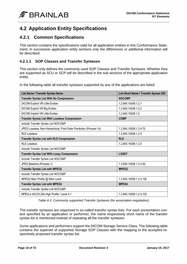
This section only defines the commonly used SOP Classes and Transfer Syntaxes. Whether they are supported as SCU or SCP will be described in the sub sections of the appropriate application entity. In the following table all transfer syntaxes supported by any of the applications are listed:
List Name / Transfer Syntax Name List Short Name / Transfer Syntax UID
Transfer Syntax List With No Compression NOCOMP
DICOM Explicit VR Little Endian 1.2.840.10008.1.2.1
DICOM Explicit VR Big Endian 1.2.840.10008.1.2.2
DICOM Implicit VR Little Endian 1.2.840.10008.1.2
Transfer Syntax List With Lossless Compression COMP
Include Transfer Syntax List NOCOMP
JPEG Lossless, Non-Hierarchical, First-Order Prediction (Process 14) 1.2.840.10008.1.2.4.70
RLE Lossless 1.2.840.10008.1.2.5
Transfer Syntax List with RLE Compression RLE
RLE Lossless 1.2.840.10008.1.2.5
Include Transfer Syntax List NOCOMP
Transfer Syntax List With Lossy Compression LOSSY
Include Transfer Syntax List NOCOMP
JPEG Baseline (Process 1) 1.2.840.10008.1.2.4.50
Transfer Syntax List with MPEG2 MPEG2
Include Transfer Syntax List NOCOMP
MPEG2 Main Profile @ Main Level 1.2.840.10008.1.2.4.100
Transfer Syntax List with MPEG4 MPEG4
Include Transfer Syntax List NOCOMP
MPEG-4 AVC/H.264 High Profile / Level 4.1 1.2.840.10008.1.2.4.102
Table 4-1: Commonly supported Transfer Syntaxes (for association negotiation)
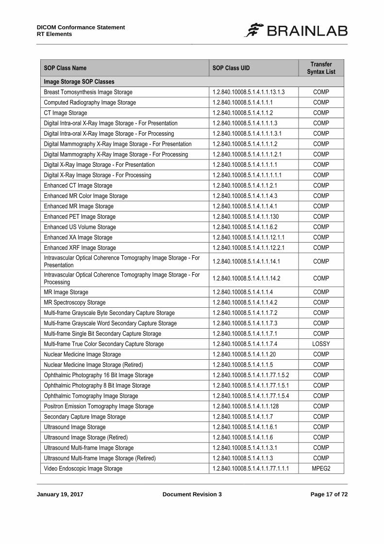
The transfer syntaxes are organized in so-called transfer syntax lists. For each presentation con-text specified by an application or performer, the name respectively short name of the transfer syntax list is mentioned instead of repeating all the transfer syntaxes. Some applications and performers support the DICOM Storage Service Class. The following table contains the superset of supported Storage SOP Classes with the mapping to the accepted re-spectively proposed transfer syntax list.
DICOM Conformance Statement RT Elements
January 19, 2017 Document Revision 3 Page 17 of 72
SOP Class Name SOP Class UID Transfer
Syntax List
Image Storage SOP Classes
Breast Tomosynthesis Image Storage 1.2.840.10008.5.1.4.1.1.13.1.3 COMP
Computed Radiography Image Storage 1.2.840.10008.5.1.4.1.1.1 COMP
CT Image Storage 1.2.840.10008.5.1.4.1.1.2 COMP
Digital Intra-oral X-Ray Image Storage - For Presentation 1.2.840.10008.5.1.4.1.1.1.3 COMP
Digital Intra-oral X-Ray Image Storage - For Processing 1.2.840.10008.5.1.4.1.1.1.3.1 COMP
Digital Mammography X-Ray Image Storage - For Presentation 1.2.840.10008.5.1.4.1.1.1.2 COMP
Digital Mammography X-Ray Image Storage - For Processing 1.2.840.10008.5.1.4.1.1.1.2.1 COMP
Digital X-Ray Image Storage - For Presentation 1.2.840.10008.5.1.4.1.1.1.1 COMP
Digital X-Ray Image Storage - For Processing 1.2.840.10008.5.1.4.1.1.1.1.1 COMP
Enhanced CT Image Storage 1.2.840.10008.5.1.4.1.1.2.1 COMP
Enhanced MR Color Image Storage 1.2.840.10008.5.1.4.1.1.4.3 COMP
Enhanced MR Image Storage 1.2.840.10008.5.1.4.1.1.4.1 COMP
Enhanced PET Image Storage 1.2.840.10008.5.1.4.1.1.130 COMP
Enhanced US Volume Storage 1.2.840.10008.5.1.4.1.1.6.2 COMP
Enhanced XA Image Storage 1.2.840.10008.5.1.4.1.1.12.1.1 COMP
Enhanced XRF Image Storage 1.2.840.10008.5.1.4.1.1.12.2.1 COMP
Intravascular Optical Coherence Tomography Image Storage - For Presentation
1.2.840.10008.5.1.4.1.1.14.1 COMP
Intravascular Optical Coherence Tomography Image Storage - For Processing
1.2.840.10008.5.1.4.1.1.14.2 COMP
MR Image Storage 1.2.840.10008.5.1.4.1.1.4 COMP
MR Spectroscopy Storage 1.2.840.10008.5.1.4.1.1.4.2 COMP
Multi-frame Grayscale Byte Secondary Capture Storage 1.2.840.10008.5.1.4.1.1.7.2 COMP
Multi-frame Grayscale Word Secondary Capture Storage 1.2.840.10008.5.1.4.1.1.7.3 COMP
Multi-frame Single Bit Secondary Capture Storage 1.2.840.10008.5.1.4.1.1.7.1 COMP
Multi-frame True Color Secondary Capture Storage 1.2.840.10008.5.1.4.1.1.7.4 LOSSY
Nuclear Medicine Image Storage 1.2.840.10008.5.1.4.1.1.20 COMP
Nuclear Medicine Image Storage (Retired) 1.2.840.10008.5.1.4.1.1.5 COMP
Ophthalmic Photography 16 Bit Image Storage 1.2.840.10008.5.1.4.1.1.77.1.5.2 COMP
Ophthalmic Photography 8 Bit Image Storage 1.2.840.10008.5.1.4.1.1.77.1.5.1 COMP
Ophthalmic Tomography Image Storage 1.2.840.10008.5.1.4.1.1.77.1.5.4 COMP
Positron Emission Tomography Image Storage 1.2.840.10008.5.1.4.1.1.128 COMP
Secondary Capture Image Storage 1.2.840.10008.5.1.4.1.1.7 COMP
Ultrasound Image Storage 1.2.840.10008.5.1.4.1.1.6.1 COMP
Ultrasound Image Storage (Retired) 1.2.840.10008.5.1.4.1.1.6 COMP
Ultrasound Multi-frame Image Storage 1.2.840.10008.5.1.4.1.1.3.1 COMP
Ultrasound Multi-frame Image Storage (Retired) 1.2.840.10008.5.1.4.1.1.3 COMP
Video Endoscopic Image Storage 1.2.840.10008.5.1.4.1.1.77.1.1.1 MPEG2
DICOM Conformance Statement
RT Elements
Page 18 of 72 Document Revision 3 January 19, 2017
SOP Class Name SOP Class UID Transfer
Syntax List
Video Microscopic Image Storage 1.2.840.10008.5.1.4.1.1.77.1.2.1 MPEG2
Video Photographic Image Storage 1.2.840.10008.5.1.4.1.1.77.1.4.1 MPEG2/MPEG
4
VL Endoscopic Image Storage 1.2.840.10008.5.1.4.1.1.77.1.1 COMP
VL Microscopic Image Storage 1.2.840.10008.5.1.4.1.1.77.1.2 COMP
VL Photographic Image Storage 1.2.840.10008.5.1.4.1.1.77.1.4 COMP
VL Slide-Coordinates Microscopic Image Storage 1.2.840.10008.5.1.4.1.1.77.1.3 COMP
VL Whole Slide Microscopy Image Storage 1.2.840.10008.5.1.4.1.1.77.1.6 COMP
X-Ray 3D Angiographic Image Storage 1.2.840.10008.5.1.4.1.1.13.1.1 COMP
X-Ray 3D Craniofacial Image Storage 1.2.840.10008.5.1.4.1.1.13.1.2 COMP
X-Ray Angiographic Bi-Plane Image Storage (Retired) 1.2.840.10008.5.1.4.1.1.12.3 COMP
X-Ray Angiographic Image Storage 1.2.840.10008.5.1.4.1.1.12.1 COMP
X-Ray Radiofluoroscopic Image Storage 1.2.840.10008.5.1.4.1.1.12.2 COMP
Non-Image Storage SOP Classes
Deformable Spatial Registration Storage 1.2.840.10008.5.1.4.1.1.66.3 NOCOMP
Encapsulated PDF Storage 1.2.840.10008.5.1.4.1.1.104.1 NOCOMP
Grayscale Softcopy Presentation State Storage 1.2.840.10008.5.1.4.1.1.11.1 NOCOMP
Key Object Selection Document Storage 1.2.840.10008.5.1.4.1.1.88.59 NOCOMP
Raw Data Storage 1.2.840.10008.5.1.4.1.1.66 NOCOMP
RT Dose Storage 1.2.840.10008.5.1.4.1.1.481.2 IMPL2
RT Plan Storage 1.2.840.10008.5.1.4.1.1.481.5 IMPL2
RT Structure Set Storage 1.2.840.10008.5.1.4.1.1.481.3 IMPL2
Segmentation Storage 1.2.840.10008.5.1.4.1.1.66.4 RLE
Spatial Fiducials Storage 1.2.840.10008.5.1.4.1.1.66.2 NOCOMP
Spatial Registration Storage 1.2.840.10008.5.1.4.1.1.66.1 NOCOMP
Surface Segmentation Storage 1.2.840.10008.5.1.4.1.1.66.5 NOCOMP
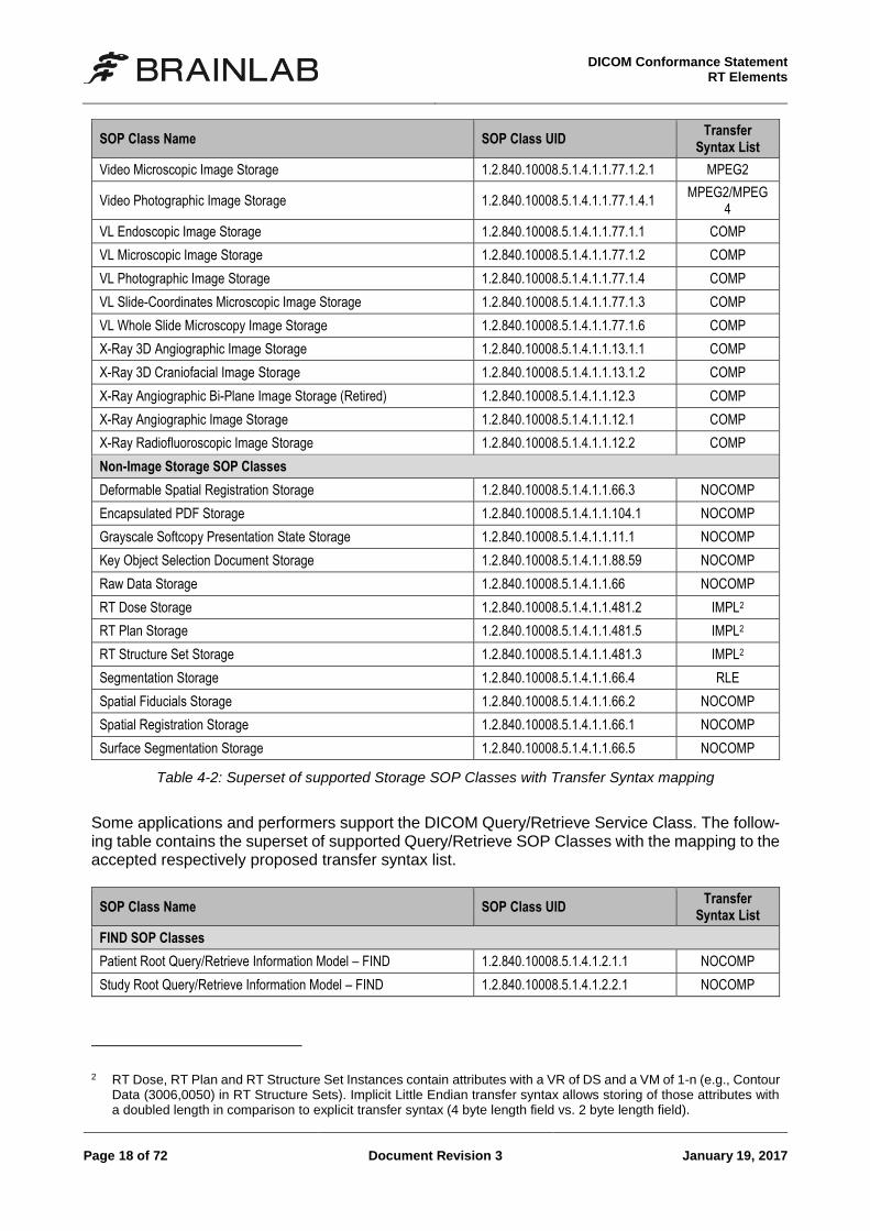
Table 4-2: Superset of supported Storage SOP Classes with Transfer Syntax mapping
Some applications and performers support the DICOM Query/Retrieve Service Class. The follow-ing table contains the superset of supported Query/Retrieve SOP Classes with the mapping to the accepted respectively proposed transfer syntax list.
SOP Class Name SOP Class UID Transfer
Syntax List
FIND SOP Classes
Patient Root Query/Retrieve Information Model – FIND 1.2.840.10008.5.1.4.1.2.1.1 NOCOMP
Study Root Query/Retrieve Information Model – FIND 1.2.840.10008.5.1.4.1.2.2.1 NOCOMP
2 RT Dose, RT Plan and RT Structure Set Instances contain attributes with a VR of DS and a VM of 1-n (e.g., Contour
Data (3006,0050) in RT Structure Sets). Implicit Little Endian transfer syntax allows storing of those attributes with a doubled length in comparison to explicit transfer syntax (4 byte length field vs. 2 byte length field).
DICOM Conformance Statement RT Elements
January 19, 2017 Document Revision 3 Page 19 of 72
SOP Class Name SOP Class UID Transfer
Syntax List
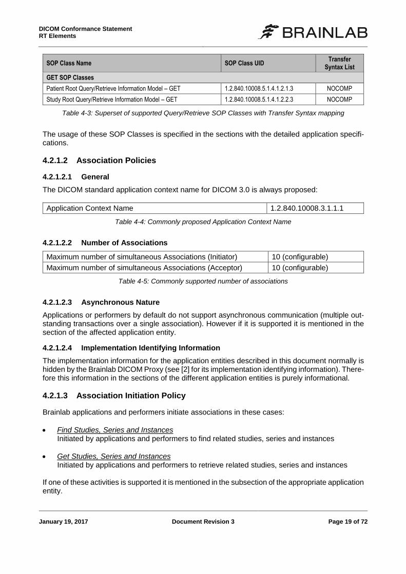
GET SOP Classes
Patient Root Query/Retrieve Information Model – GET 1.2.840.10008.5.1.4.1.2.1.3 NOCOMP
Study Root Query/Retrieve Information Model – GET 1.2.840.10008.5.1.4.1.2.2.3 NOCOMP
Table 4-3: Superset of supported Query/Retrieve SOP Classes with Transfer Syntax mapping
The usage of these SOP Classes is specified in the sections with the detailed application specifi-cations.
4.2.1.2 Association Policies
4.2.1.2.1 General
The DICOM standard application context name for DICOM 3.0 is always proposed:
Application Context Name 1.2.840.10008.3.1.1.1
Table 4-4: Commonly proposed Application Context Name
4.2.1.2.2 Number of Associations
Maximum number of simultaneous Associations (Initiator) 10 (configurable)
Maximum number of simultaneous Associations (Acceptor) 10 (configurable)
Table 4-5: Commonly supported number of associations
4.2.1.2.3 Asynchronous Nature
Applications or performers by default do not support asynchronous communication (multiple out-standing transactions over a single association). However if it is supported it is mentioned in the section of the affected application entity.
4.2.1.2.4 Implementation Identifying Information
The implementation information for the application entities described in this document normally is hidden by the Brainlab DICOM Proxy (see [2] for its implementation identifying information). There-fore this information in the sections of the different application entities is purely informational.
4.2.1.3 Association Initiation Policy
Brainlab applications and performers initiate associations in these cases:
Find Studies, Series and Instances Initiated by applications and performers to find related studies, series and instances
Get Studies, Series and Instances Initiated by applications and performers to retrieve related studies, series and instances
If one of these activities is supported it is mentioned in the subsection of the appropriate application entity.
DICOM Conformance Statement
RT Elements
Page 20 of 72 Document Revision 3 January 19, 2017
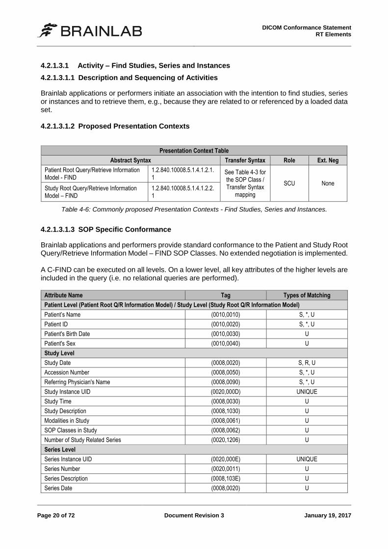
4.2.1.3.1 Activity – Find Studies, Series and Instances
4.2.1.3.1.1 Description and Sequencing of Activities
Brainlab applications or performers initiate an association with the intention to find studies, series or instances and to retrieve them, e.g., because they are related to or referenced by a loaded data set. 4.2.1.3.1.2 Proposed Presentation Contexts
Presentation Context Table
Abstract Syntax Transfer Syntax Role Ext. Neg
Patient Root Query/Retrieve Information Model - FIND
1.2.840.10008.5.1.4.1.2.1.1
See Table 4-3 for the SOP Class / Transfer Syntax
mapping
SCU None Study Root Query/Retrieve Information Model – FIND
1.2.840.10008.5.1.4.1.2.2.1
Table 4-6: Commonly proposed Presentation Contexts - Find Studies, Series and Instances.
4.2.1.3.1.3 SOP Specific Conformance
Brainlab applications and performers provide standard conformance to the Patient and Study Root Query/Retrieve Information Model – FIND SOP Classes. No extended negotiation is implemented. A C-FIND can be executed on all levels. On a lower level, all key attributes of the higher levels are included in the query (i.e. no relational queries are performed).
Attribute Name Tag Types of Matching
Patient Level (Patient Root Q/R Information Model) / Study Level (Study Root Q/R Information Model)
Patient’s Name (0010,0010) S, *, U
Patient ID (0010,0020) S, *, U
Patient's Birth Date (0010,0030) U
Patient's Sex (0010,0040) U
Study Level
Study Date (0008,0020) S, R, U
Accession Number (0008,0050) S, *, U
Referring Physician's Name (0008,0090) S, *, U
Study Instance UID (0020,000D) UNIQUE
Study Time (0008,0030) U
Study Description (0008,1030) U
Modalities in Study (0008,0061) U
SOP Classes in Study (0008,0062) U
Number of Study Related Series (0020,1206) U
Series Level
Series Instance UID (0020,000E) UNIQUE
Series Number (0020,0011) U
Series Description (0008,103E) U
Series Date (0008,0020) U
DICOM Conformance Statement RT Elements
January 19, 2017 Document Revision 3 Page 21 of 72
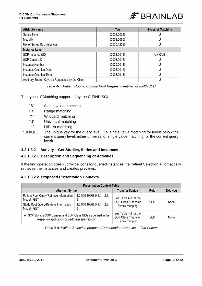
Attribute Name Tag Types of Matching
Series Time (0008,0021) U
Modality (0008,0060) U
No. of Series Rel. Instances (0020,1209) U
Instance Level
SOP Instance UID (0008,0018) UNIQUE
SOP Class UID (0008,0016) U
Instance Number (0020,0013) U
Instance Creation Date (0008,0012) U
Instance Creation Time (0008,0013) U
Arbitrary Search Keys as Requested by the Client * U
Table 4-7: Patient Root and Study Root Request Identifier for FIND-SCU
The types of Matching supported by the C-FIND SCU:
“S” Single value matching
“R” Range matching
“*” Wildcard matching
“U” Universal matching
“L” UID list matching
“UNIQUE” The unique key for the query level, (i.e. single value matching for levels below the current query level, either universal or single value matching for the current query level)
4.2.1.3.2 Activity – Get Studies, Series and Instances
4.2.1.3.2.1 Description and Sequencing of Activities
If the find operation doesn’t provide icons for queried instances the Patient Selection automatically retrieves the instances and creates previews. 4.2.1.3.2.2 Proposed Presentation Contexts
Presentation Context Table
Abstract Syntax Transfer Syntax Role Ext. Neg
Patient Root Query/Retrieve Information Model - GET
1.2.840.10008.5.1.4.1.2.1.3 See Table 4-3 for the
SOP Class / Transfer Syntax mapping
SCU None Study Root Query/Retrieve Information Model - GET
1.2.840.10008.5.1.4.1.2.2.3
All SCP Storage SOP Classes and SOP Class UIDs as defined in the respective application or performer specification
See Table 4-2 for the SOP Class / Transfer
Syntax mapping SCP None
Table 4-8: Patient Selection proposed Presentation Contexts – Find Patient
DICOM Conformance Statement
RT Elements
Page 22 of 72 Document Revision 3 January 19, 2017
4.2.1.3.2.3 SOP Specific Conformance
The Patient Selection provides standard conformance to the DICOM Patient and Study Root Query/Retrieve - GET SOP Class and to the DICOM Storage SOP Classes. No extended negoti-ation is implemented.
4.2.1.4 Association Acceptance Policy
Brainlab applications and performers do not directly accept associations. All external communica-tion is handled by the DICOM Proxy (see [2] for details). Nevertheless in the sub sections of the different application entities the association acceptance will be described to define the SOP Classes they support. 4.2.1.4.1 Transfer Syntax Selection Policy
Brainlab applications and performers in general accept transfer syntaxes in with no compression (explicit before implicit) before those with lossless compression and at least those with lossy com-pression. At least the order of the transfer syntaxes in the assigned transfer syntax list is the order of acceptance.
DICOM Conformance Statement RT Elements
January 19, 2017 Document Revision 3 Page 23 of 72
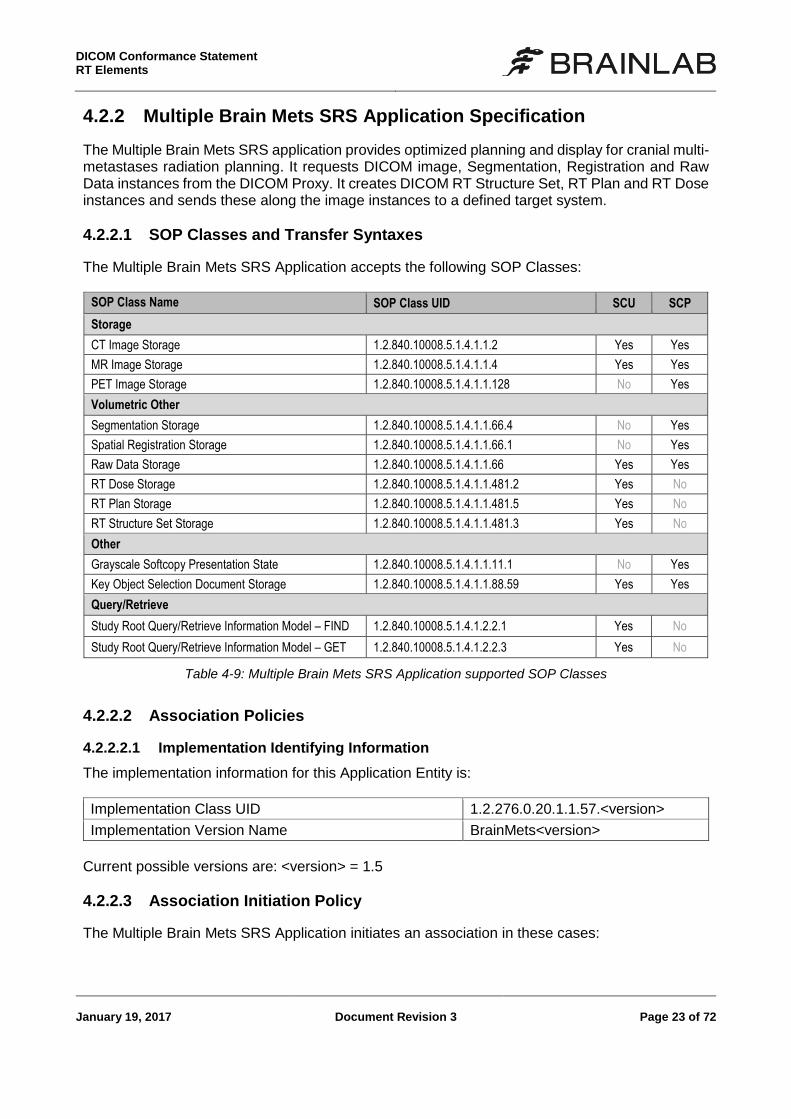
4.2.2 Multiple Brain Mets SRS Application Specification
The Multiple Brain Mets SRS application provides optimized planning and display for cranial multi-metastases radiation planning. It requests DICOM image, Segmentation, Registration and Raw Data instances from the DICOM Proxy. It creates DICOM RT Structure Set, RT Plan and RT Dose instances and sends these along the image instances to a defined target system.
4.2.2.1 SOP Classes and Transfer Syntaxes
The Multiple Brain Mets SRS Application accepts the following SOP Classes:
SOP Class Name SOP Class UID SCU SCP
Storage
CT Image Storage 1.2.840.10008.5.1.4.1.1.2 Yes Yes
MR Image Storage 1.2.840.10008.5.1.4.1.1.4 Yes Yes
PET Image Storage 1.2.840.10008.5.1.4.1.1.128 No Yes
Volumetric Other
Segmentation Storage 1.2.840.10008.5.1.4.1.1.66.4 No Yes
Spatial Registration Storage 1.2.840.10008.5.1.4.1.1.66.1 No Yes
Raw Data Storage 1.2.840.10008.5.1.4.1.1.66 Yes Yes
RT Dose Storage 1.2.840.10008.5.1.4.1.1.481.2 Yes No
RT Plan Storage 1.2.840.10008.5.1.4.1.1.481.5 Yes No
RT Structure Set Storage 1.2.840.10008.5.1.4.1.1.481.3 Yes No
Other
Grayscale Softcopy Presentation State 1.2.840.10008.5.1.4.1.1.11.1 No Yes
Key Object Selection Document Storage 1.2.840.10008.5.1.4.1.1.88.59 Yes Yes
Query/Retrieve
Study Root Query/Retrieve Information Model – FIND 1.2.840.10008.5.1.4.1.2.2.1 Yes No
Study Root Query/Retrieve Information Model – GET 1.2.840.10008.5.1.4.1.2.2.3 Yes No
Table 4-9: Multiple Brain Mets SRS Application supported SOP Classes
4.2.2.2 Association Policies
4.2.2.2.1 Implementation Identifying Information
The implementation information for this Application Entity is:
Implementation Class UID 1.2.276.0.20.1.1.57.<version>
Implementation Version Name BrainMets<version>
Current possible versions are: <version> = 1.5
4.2.2.3 Association Initiation Policy
The Multiple Brain Mets SRS Application initiates an association in these cases:
DICOM Conformance Statement
RT Elements
Page 24 of 72 Document Revision 3 January 19, 2017
Find Studies, Series and Instances Initiated to find related studies, series and instances
Get Studies, Series and Instances Initiated to retrieve related studies, series and instances
Save Instances The user created a new radiotherapy treatment plan.
4.2.2.3.1 Activity – Find Studies, Series and Instances
See Common Specifications, section 4.2.1.3.1. 4.2.2.3.2 Activity – Get Studies, Series and Instances
See Common Specifications, section 4.2.1.3.1., restricted to Study Root Query/Retrieve Infor-mation Model – GET and to all SCP Storage SOP Classes and SOP Class UIDs as listed in Table 4-9. 4.2.2.3.3 Activity – Save Instances
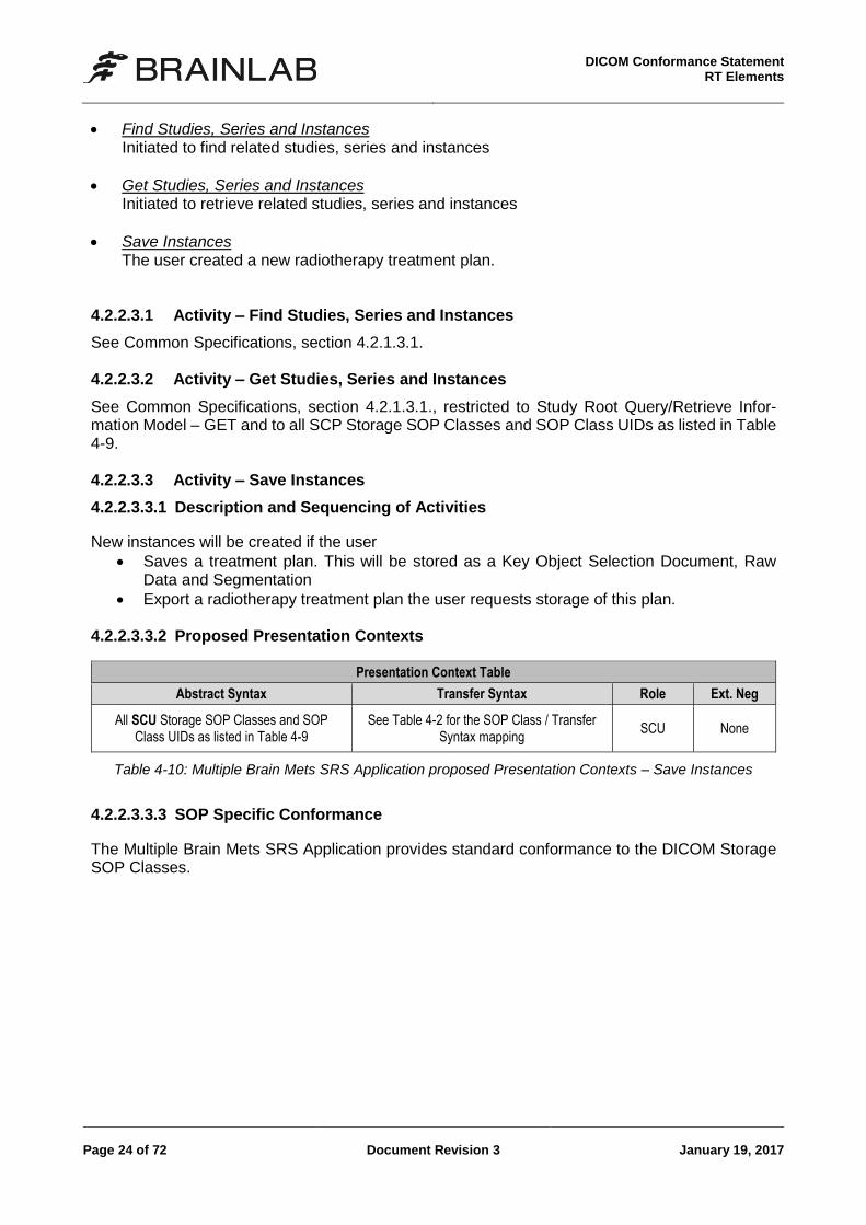
4.2.2.3.3.1 Description and Sequencing of Activities
New instances will be created if the user
Saves a treatment plan. This will be stored as a Key Object Selection Document, Raw Data and Segmentation
Export a radiotherapy treatment plan the user requests storage of this plan. 4.2.2.3.3.2 Proposed Presentation Contexts
Presentation Context Table
Abstract Syntax Transfer Syntax Role Ext. Neg
All SCU Storage SOP Classes and SOP Class UIDs as listed in Table 4-9
See Table 4-2 for the SOP Class / Transfer Syntax mapping
SCU None
Table 4-10: Multiple Brain Mets SRS Application proposed Presentation Contexts – Save Instances
4.2.2.3.3.3 SOP Specific Conformance
The Multiple Brain Mets SRS Application provides standard conformance to the DICOM Storage SOP Classes.
DICOM Conformance Statement RT Elements
January 19, 2017 Document Revision 3 Page 25 of 72
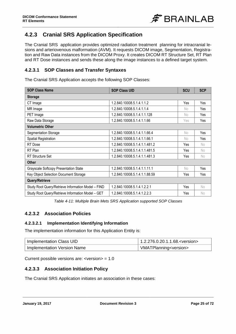
4.2.3 Cranial SRS Application Specification
The Cranial SRS application provides optimized radiation treatment planning for intracranial le-sions and arteriovenous malformation (AVM). It requests DICOM image, Segmentation, Registra-tion and Raw Data instances from the DICOM Proxy. It creates DICOM RT Structure Set, RT Plan and RT Dose instances and sends these along the image instances to a defined target system.
4.2.3.1 SOP Classes and Transfer Syntaxes
The Cranial SRS Application accepts the following SOP Classes:
SOP Class Name SOP Class UID SCU SCP
Storage
CT Image 1.2.840.10008.5.1.4.1.1.2 Yes Yes
MR Image 1.2.840.10008.5.1.4.1.1.4 No Yes
PET Image 1.2.840.10008.5.1.4.1.1.128 No Yes
Raw Data Storage 1.2.840.10008.5.1.4.1.1.66 Yes Yes
Volumetric Other
Segmentation Storage 1.2.840.10008.5.1.4.1.1.66.4 No Yes
Spatial Registration 1.2.840.10008.5.1.4.1.1.66.1 No Yes
RT Dose 1.2.840.10008.5.1.4.1.1.481.2 Yes No
RT Plan 1.2.840.10008.5.1.4.1.1.481.5 Yes No
RT Structure Set 1.2.840.10008.5.1.4.1.1.481.3 Yes No
Other
Grayscale Softcopy Presentation State 1.2.840.10008.5.1.4.1.1.11.1 No Yes
Key Object Selection Document Storage 1.2.840.10008.5.1.4.1.1.88.59 Yes Yes
Query/Retrieve
Study Root Query/Retrieve Information Model – FIND 1.2.840.10008.5.1.4.1.2.2.1 Yes No
Study Root Query/Retrieve Information Model – GET 1.2.840.10008.5.1.4.1.2.2.3 Yes No
Table 4-11: Multiple Brain Mets SRS Application supported SOP Classes
4.2.3.2 Association Policies
4.2.3.2.1 Implementation Identifying Information
The implementation information for this Application Entity is:
Implementation Class UID 1.2.276.0.20.1.1.68.<version>
Implementation Version Name VMATPlanning<version>
Current possible versions are: <version> = 1.0
4.2.3.3 Association Initiation Policy
The Cranial SRS Application initiates an association in these cases:

DICOM Conformance Statement
RT Elements
Page 26 of 72 Document Revision 3 January 19, 2017
Find Studies, Series and Instances Initiated to find related studies, series and instances
Get Studies, Series and Instances Initiated to retrieve related studies, series and instances
Save Instances The user created a new radiotherapy treatment plan.
4.2.3.3.1 Activity – Find Studies, Series and Instances
See Common Specifications, section 4.2.1.3.1. 4.2.3.3.2 Activity – Get Studies, Series and Instances
See Common Specifications, section 4.2.1.3.2, restricted to Study Root Query/Retrieve Infor-mation Model – GET and to all SCP Storage SOP Classes and SOP Class UIDs as listed in Table 4-11. 4.2.3.3.3 Activity – Save Instances
4.2.3.3.3.1 Description and Sequencing of Activities
New instances will be created if the user
Saves a treatment plan. This will be stored as a Key Object Selection Document, Raw Data and Segmentation
Export a radiotherapy treatment plan the user requests storage of this plan. 4.2.3.3.3.2 Proposed Presentation Contexts
Presentation Context Table
Abstract Syntax Transfer Syntax Role Ext. Neg
All SCU Storage SOP Classes and SOP Class UIDs as listed in Table 4-11
See Table 4-2 for the SOP Class / Transfer Syntax mapping
SCU None
Table 4-12: Cranial SRS Application proposed Presentation Contexts – Save Instances
4.2.3.3.3.3 SOP Specific Conformance
The Cranial SRS Application provides standard conformance to the DICOM Storage SOP Clas-ses.
DICOM Conformance Statement RT Elements
January 19, 2017 Document Revision 3 Page 27 of 72
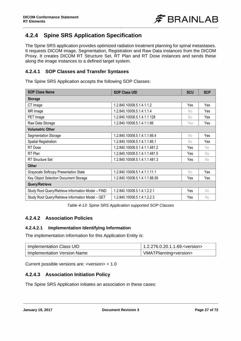
4.2.4 Spine SRS Application Specification
The Spine SRS application provides optimized radiation treatment planning for spinal metastases. It requests DICOM image, Segmentation, Registration and Raw Data instances from the DICOM Proxy. It creates DICOM RT Structure Set, RT Plan and RT Dose instances and sends these along the image instances to a defined target system.
4.2.4.1 SOP Classes and Transfer Syntaxes
The Spine SRS Application accepts the following SOP Classes:
SOP Class Name SOP Class UID SCU SCP
Storage
CT Image 1.2.840.10008.5.1.4.1.1.2 Yes Yes
MR Image 1.2.840.10008.5.1.4.1.1.4 No Yes
PET Image 1.2.840.10008.5.1.4.1.1.128 No Yes
Raw Data Storage 1.2.840.10008.5.1.4.1.1.66 Yes Yes
Volumetric Other
Segmentation Storage 1.2.840.10008.5.1.4.1.1.66.4 No Yes
Spatial Registration 1.2.840.10008.5.1.4.1.1.66.1 No Yes
RT Dose 1.2.840.10008.5.1.4.1.1.481.2 Yes No
RT Plan 1.2.840.10008.5.1.4.1.1.481.5 Yes No
RT Structure Set 1.2.840.10008.5.1.4.1.1.481.3 Yes No
Other
Grayscale Softcopy Presentation State 1.2.840.10008.5.1.4.1.1.11.1 No Yes
Key Object Selection Document Storage 1.2.840.10008.5.1.4.1.1.88.59 Yes Yes
Query/Retrieve
Study Root Query/Retrieve Information Model – FIND 1.2.840.10008.5.1.4.1.2.2.1 Yes No
Study Root Query/Retrieve Information Model – GET 1.2.840.10008.5.1.4.1.2.2.3 Yes No
Table 4-13: Spine SRS Application supported SOP Classes
4.2.4.2 Association Policies
4.2.4.2.1 Implementation Identifying Information
The implementation information for this Application Entity is:
Implementation Class UID 1.2.276.0.20.1.1.69.<version>
Implementation Version Name VMATPlanning<version>
Current possible versions are: <version> = 1.0
4.2.4.3 Association Initiation Policy
The Spine SRS Application initiates an association in these cases:
DICOM Conformance Statement
RT Elements
Page 28 of 72 Document Revision 3 January 19, 2017
Find Studies, Series and Instances Initiated to find related studies, series and instances
Get Studies, Series and Instances Initiated to retrieve related studies, series and instances
Save Instances The user created a new radiotherapy treatment plan.
4.2.4.3.1 Activity – Find Studies, Series and Instances
See Common Specifications, section 4.2.1.3.1. 4.2.4.3.2 Activity – Get Studies, Series and Instances
See Common Specifications, section 4.2.1.3.2, restricted to Study Root Query/Retrieve Infor-mation Model – GET and to all SCP Storage SOP Classes and SOP Class UIDs as listed in Table 4-13. 4.2.4.3.3 Activity – Save Instances
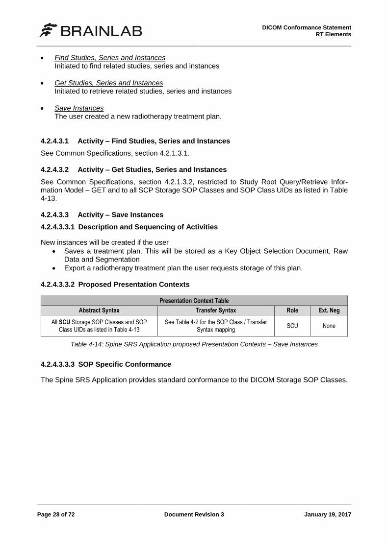
4.2.4.3.3.1 Description and Sequencing of Activities
New instances will be created if the user
Saves a treatment plan. This will be stored as a Key Object Selection Document, Raw Data and Segmentation
Export a radiotherapy treatment plan the user requests storage of this plan. 4.2.4.3.3.2 Proposed Presentation Contexts
Presentation Context Table
Abstract Syntax Transfer Syntax Role Ext. Neg
All SCU Storage SOP Classes and SOP Class UIDs as listed in Table 4-13
See Table 4-2 for the SOP Class / Transfer Syntax mapping
SCU None
Table 4-14: Spine SRS Application proposed Presentation Contexts – Save Instances
4.2.4.3.3.3 SOP Specific Conformance
The Spine SRS Application provides standard conformance to the DICOM Storage SOP Classes.
DICOM Conformance Statement RT Elements
January 19, 2017 Document Revision 3 Page 29 of 72
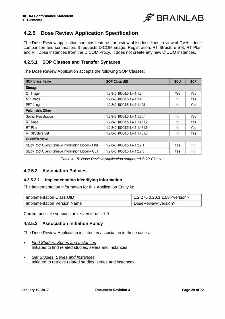
4.2.5 Dose Review Application Specification
The Dose Review application contains features for review of isodose lines, review of DVHs, dose comparison and summation. It requests DICOM image, Registration, RT Structure Set, RT Plan and RT Dose instances from the DICOM Proxy. It does not create any new DICOM instances.
4.2.5.1 SOP Classes and Transfer Syntaxes
The Dose Review Application accepts the following SOP Classes:
SOP Class Name SOP Class UID SCU SCP
Storage
CT Image 1.2.840.10008.5.1.4.1.1.2 Yes Yes
MR Image 1.2.840.10008.5.1.4.1.1.4 No Yes
PET Image 1.2.840.10008.5.1.4.1.1.128 No Yes
Volumetric Other
Spatial Registration 1.2.840.10008.5.1.4.1.1.66.1 No Yes
RT Dose 1.2.840.10008.5.1.4.1.1.481.2 No Yes
RT Plan 1.2.840.10008.5.1.4.1.1.481.5 No Yes
RT Structure Set 1.2.840.10008.5.1.4.1.1.481.3 No Yes
Query/Retrieve
Study Root Query/Retrieve Information Model – FIND 1.2.840.10008.5.1.4.1.2.2.1 Yes No
Study Root Query/Retrieve Information Model – GET 1.2.840.10008.5.1.4.1.2.2.3 Yes No
Table 4-15: Dose Review Application supported SOP Classes
4.2.5.2 Association Policies
4.2.5.2.1 Implementation Identifying Information
The implementation information for this Application Entity is:
Implementation Class UID 1.2.276.0.20.1.1.58.<version>
Implementation Version Name DoseReview<version>
Current possible versions are: <version> = 1.0
4.2.5.3 Association Initiation Policy
The Dose Review Application initiates an association in these cases:
Find Studies, Series and Instances Initiated to find related studies, series and instances
Get Studies, Series and Instances Initiated to retrieve related studies, series and instances
DICOM Conformance Statement
RT Elements
Page 30 of 72 Document Revision 3 January 19, 2017
4.2.5.3.1 Activity – Find Studies, Series and Instances
See Common Specifications, section 4.2.1.3.1. 4.2.5.3.2 Activity – Get Studies, Series and Instances
See Common Specifications, section 4.2.1.3.2, restricted to Study Root Query/Retrieve Infor-mation Model – GET and to all SCP Storage SOP Classes and SOP Class UIDs as listed in Table 4-15.
DICOM Conformance Statement RT Elements
January 19, 2017 Document Revision 3 Page 31 of 72
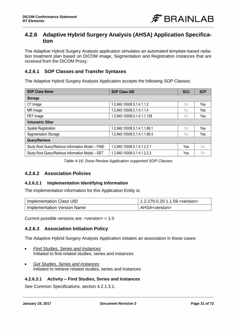
4.2.6 Adaptive Hybrid Surgery Analysis (AHSA) Application Specifica-tion
The Adaptive Hybrid Surgery Analysis application simulates an automated template-based radia-tion treatment plan based on DICOM image, Segmentation and Registration instances that are received from the DICOM Proxy.
4.2.6.1 SOP Classes and Transfer Syntaxes
The Adaptive Hybrid Surgery Analysis Application accepts the following SOP Classes:
SOP Class Name SOP Class UID SCU SCP
Storage
CT Image 1.2.840.10008.5.1.4.1.1.2 No Yes
MR Image 1.2.840.10008.5.1.4.1.1.4 No Yes
PET Image 1.2.840.10008.5.1.4.1.1.128 No Yes
Volumetric Other
Spatial Registration 1.2.840.10008.5.1.4.1.1.66.1 No Yes
Segmentation Storage 1.2.840.10008.5.1.4.1.1.66.4 No Yes
Query/Retrieve
Study Root Query/Retrieve Information Model – FIND 1.2.840.10008.5.1.4.1.2.2.1 Yes No
Study Root Query/Retrieve Information Model – GET 1.2.840.10008.5.1.4.1.2.2.3 Yes No
Table 4-16: Dose Review Application supported SOP Classes
4.2.6.2 Association Policies
4.2.6.2.1 Implementation Identifying Information
The implementation information for this Application Entity is:
Implementation Class UID 1.2.276.0.20.1.1.59.<version>
Implementation Version Name AHSA<version>
Current possible versions are: <version> = 1.0
4.2.6.3 Association Initiation Policy
The Adaptive Hybrid Surgery Analysis Application initiates an association in these cases:
Find Studies, Series and Instances Initiated to find related studies, series and instances
Get Studies, Series and Instances Initiated to retrieve related studies, series and instances
4.2.6.3.1 Activity – Find Studies, Series and Instances
See Common Specifications, section 4.2.1.3.1.
DICOM Conformance Statement
RT Elements
Page 32 of 72 Document Revision 3 January 19, 2017
4.2.6.3.2 Activity – Get Studies, Series and Instances
See Common Specifications, section 4.2.1.3.2, restricted to Study Root Query/Retrieve Infor-mation Model – GET and to all SCP Storage SOP Classes and SOP Class UIDs as listed in Table 4-16.
DICOM Conformance Statement RT Elements
January 19, 2017 Document Revision 3 Page 33 of 72
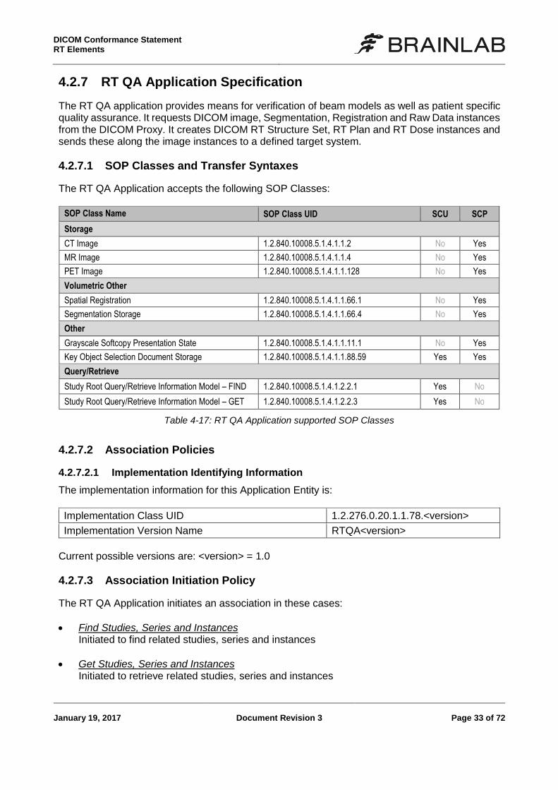
4.2.7 RT QA Application Specification
The RT QA application provides means for verification of beam models as well as patient specific quality assurance. It requests DICOM image, Segmentation, Registration and Raw Data instances from the DICOM Proxy. It creates DICOM RT Structure Set, RT Plan and RT Dose instances and sends these along the image instances to a defined target system.
4.2.7.1 SOP Classes and Transfer Syntaxes
The RT QA Application accepts the following SOP Classes:
SOP Class Name SOP Class UID SCU SCP
Storage
CT Image 1.2.840.10008.5.1.4.1.1.2 No Yes
MR Image 1.2.840.10008.5.1.4.1.1.4 No Yes
PET Image 1.2.840.10008.5.1.4.1.1.128 No Yes
Volumetric Other
Spatial Registration 1.2.840.10008.5.1.4.1.1.66.1 No Yes
Segmentation Storage 1.2.840.10008.5.1.4.1.1.66.4 No Yes
Other
Grayscale Softcopy Presentation State 1.2.840.10008.5.1.4.1.1.11.1 No Yes
Key Object Selection Document Storage 1.2.840.10008.5.1.4.1.1.88.59 Yes Yes
Query/Retrieve
Study Root Query/Retrieve Information Model – FIND 1.2.840.10008.5.1.4.1.2.2.1 Yes No
Study Root Query/Retrieve Information Model – GET 1.2.840.10008.5.1.4.1.2.2.3 Yes No
Table 4-17: RT QA Application supported SOP Classes
4.2.7.2 Association Policies
4.2.7.2.1 Implementation Identifying Information
The implementation information for this Application Entity is:
Implementation Class UID 1.2.276.0.20.1.1.78.<version>
Implementation Version Name RTQA<version>
Current possible versions are: <version> = 1.0
4.2.7.3 Association Initiation Policy
The RT QA Application initiates an association in these cases:
Find Studies, Series and Instances Initiated to find related studies, series and instances
Get Studies, Series and Instances Initiated to retrieve related studies, series and instances
DICOM Conformance Statement
RT Elements
Page 34 of 72 Document Revision 3 January 19, 2017
Save Instances The user created a new radiotherapy treatment plan.
4.2.7.3.1 Activity – Find Studies, Series and Instances
See Common Specifications, section 4.2.1.3.1. 4.2.7.3.2 Activity – Get Studies, Series and Instances
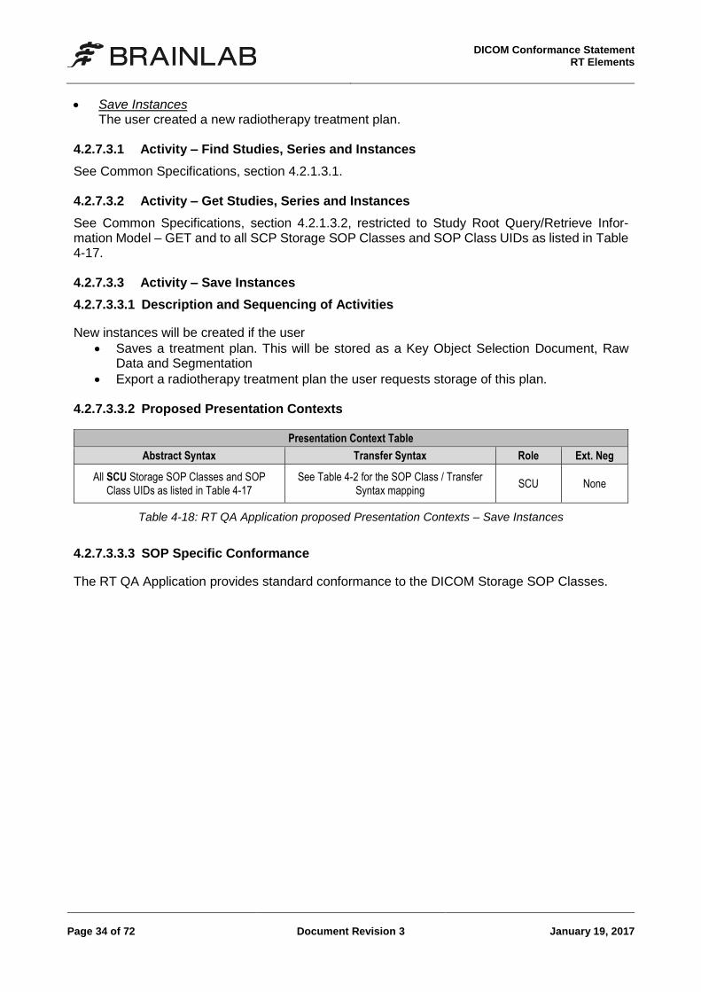
See Common Specifications, section 4.2.1.3.2, restricted to Study Root Query/Retrieve Infor-mation Model – GET and to all SCP Storage SOP Classes and SOP Class UIDs as listed in Table 4-17. 4.2.7.3.3 Activity – Save Instances
4.2.7.3.3.1 Description and Sequencing of Activities
New instances will be created if the user
Saves a treatment plan. This will be stored as a Key Object Selection Document, Raw Data and Segmentation
Export a radiotherapy treatment plan the user requests storage of this plan. 4.2.7.3.3.2 Proposed Presentation Contexts
Presentation Context Table
Abstract Syntax Transfer Syntax Role Ext. Neg
All SCU Storage SOP Classes and SOP Class UIDs as listed in Table 4-17
See Table 4-2 for the SOP Class / Transfer Syntax mapping
SCU None
Table 4-18: RT QA Application proposed Presentation Contexts – Save Instances
4.2.7.3.3.3 SOP Specific Conformance
The RT QA Application provides standard conformance to the DICOM Storage SOP Classes.
DICOM Conformance Statement RT Elements
January 19, 2017 Document Revision 3 Page 35 of 72
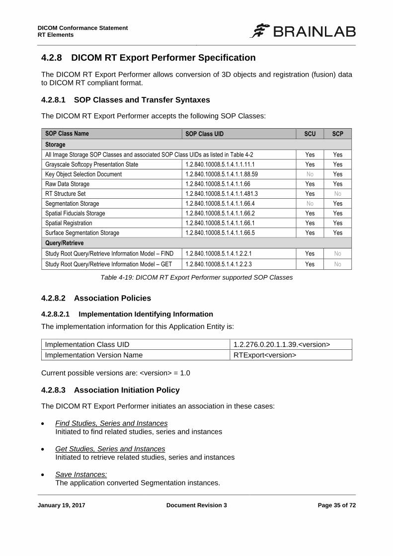
4.2.8 DICOM RT Export Performer Specification
The DICOM RT Export Performer allows conversion of 3D objects and registration (fusion) data to DICOM RT compliant format.
4.2.8.1 SOP Classes and Transfer Syntaxes
The DICOM RT Export Performer accepts the following SOP Classes:
SOP Class Name SOP Class UID SCU SCP
Storage
All Image Storage SOP Classes and associated SOP Class UIDs as listed in Table 4-2 Yes Yes
Grayscale Softcopy Presentation State 1.2.840.10008.5.1.4.1.1.11.1 Yes Yes
Key Object Selection Document 1.2.840.10008.5.1.4.1.1.88.59 No Yes
Raw Data Storage 1.2.840.10008.5.1.4.1.1.66 Yes Yes
RT Structure Set 1.2.840.10008.5.1.4.1.1.481.3 Yes No
Segmentation Storage 1.2.840.10008.5.1.4.1.1.66.4 No Yes
Spatial Fiducials Storage 1.2.840.10008.5.1.4.1.1.66.2 Yes Yes
Spatial Registration 1.2.840.10008.5.1.4.1.1.66.1 Yes Yes
Surface Segmentation Storage 1.2.840.10008.5.1.4.1.1.66.5 Yes Yes
Query/Retrieve
Study Root Query/Retrieve Information Model – FIND 1.2.840.10008.5.1.4.1.2.2.1 Yes No
Study Root Query/Retrieve Information Model – GET 1.2.840.10008.5.1.4.1.2.2.3 Yes No
Table 4-19: DICOM RT Export Performer supported SOP Classes
4.2.8.2 Association Policies
4.2.8.2.1 Implementation Identifying Information
The implementation information for this Application Entity is:
Implementation Class UID 1.2.276.0.20.1.1.39.<version>
Implementation Version Name RTExport<version>
Current possible versions are: <version> = 1.0
4.2.8.3 Association Initiation Policy
The DICOM RT Export Performer initiates an association in these cases:
Find Studies, Series and Instances Initiated to find related studies, series and instances
Get Studies, Series and Instances Initiated to retrieve related studies, series and instances
Save Instances: The application converted Segmentation instances.
DICOM Conformance Statement
RT Elements
Page 36 of 72 Document Revision 3 January 19, 2017
4.2.8.3.1 Activity – Find Studies, Series and Instances
See Common Specifications, section 4.2.1.3.1. 4.2.8.3.2 Activity – Get Studies, Series and Instances
See Common Specifications, section 4.2.1.3.2, restricted to Study Root Query/Retrieve Infor-mation Model – GET and to all SCP Storage SOP Classes and SOP Class UIDs as listed in Table 4-19. 4.2.8.3.3 Activity – Save Instances
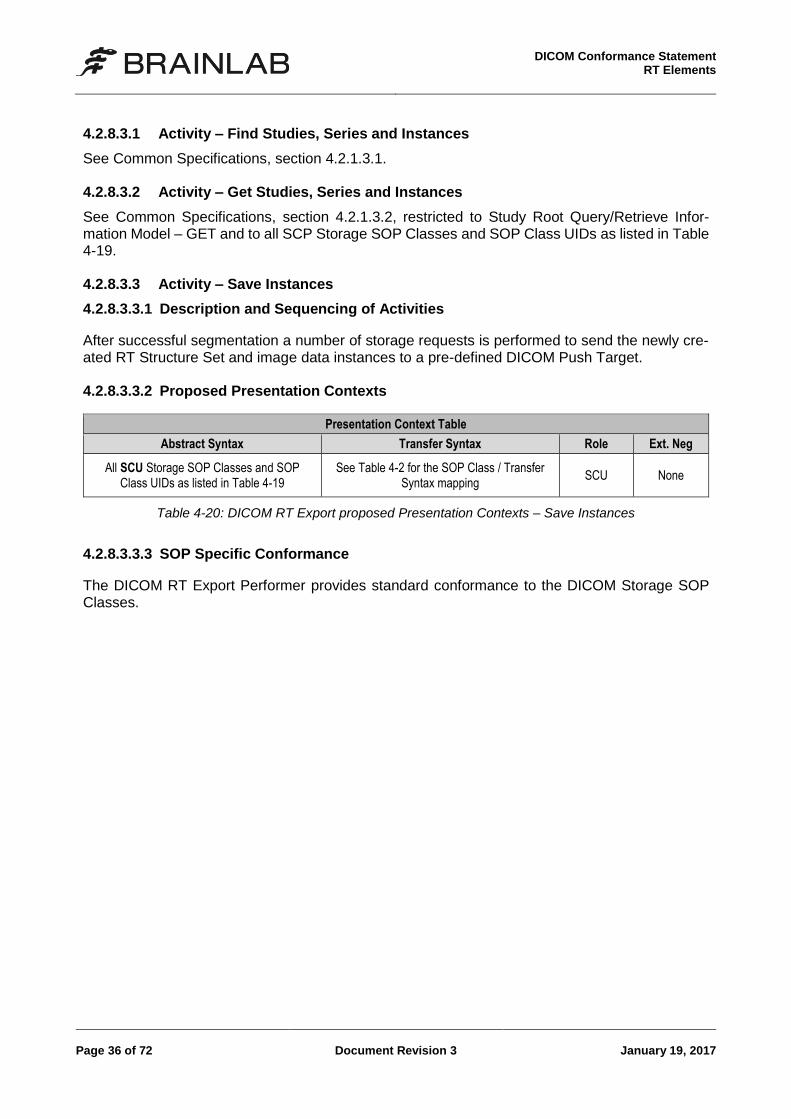
4.2.8.3.3.1 Description and Sequencing of Activities
After successful segmentation a number of storage requests is performed to send the newly cre-ated RT Structure Set and image data instances to a pre-defined DICOM Push Target. 4.2.8.3.3.2 Proposed Presentation Contexts
Presentation Context Table
Abstract Syntax Transfer Syntax Role Ext. Neg
All SCU Storage SOP Classes and SOP Class UIDs as listed in Table 4-19
See Table 4-2 for the SOP Class / Transfer Syntax mapping
SCU None
Table 4-20: DICOM RT Export proposed Presentation Contexts – Save Instances
4.2.8.3.3.3 SOP Specific Conformance
The DICOM RT Export Performer provides standard conformance to the DICOM Storage SOP Classes.
DICOM Conformance Statement RT Elements
January 19, 2017 Document Revision 3 Page 37 of 72
4.3 Network Interfaces
4.3.1 Physical Network Interface
The applications and performers support the DICOM upper layer using TCP/IP and are indifferent to the physical medium over which TCP/IP executes. The applications and performers inherit this from the operating system upon which they are executed.
4.3.2 Additional Protocols
The usage of DNS and DHCP is possible and is based on the network configuration of the oper-ating system upon which the applications and performers execute.

DICOM Conformance Statement RT Elements
January 19, 2017 Document Revision 3 Page 39 of 72
5 Media Interchange
5.1 Implementation Model
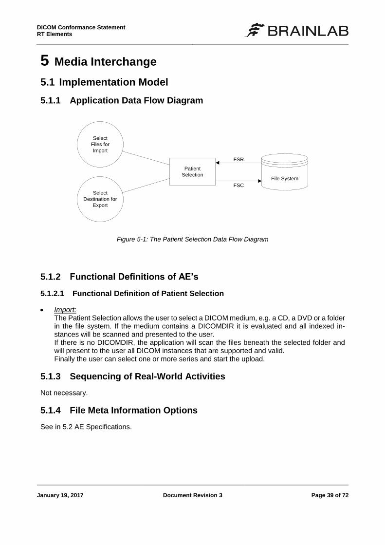
5.1.1 Application Data Flow Diagram
File System
Patient
Selection
FSR
Select
Files for
Import
Select
Destination for
Export
FSC
Figure 5-1: The Patient Selection Data Flow Diagram
5.1.2 Functional Definitions of AE’s
5.1.2.1 Functional Definition of Patient Selection
Import: The Patient Selection allows the user to select a DICOM medium, e.g. a CD, a DVD or a folder in the file system. If the medium contains a DICOMDIR it is evaluated and all indexed in-stances will be scanned and presented to the user. If there is no DICOMDIR, the application will scan the files beneath the selected folder and will present to the user all DICOM instances that are supported and valid. Finally the user can select one or more series and start the upload.
5.1.3 Sequencing of Real-World Activities
Not necessary.
5.1.4 File Meta Information Options
See in 5.2 AE Specifications.
DICOM Conformance Statement
RT Elements
Page 40 of 72 Document Revision 3 January 19, 2017
5.2 AE Specifications
5.2.1 Common Export Specifications
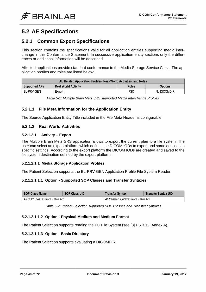
This section contains the specifications valid for all application entities supporting media inter-change in this Conformance Statement. In successive application entity sections only the differ-ences or additional information will be described. Affected applications provide standard conformance to the Media Storage Service Class. The ap-plication profiles and roles are listed below:
AE Related Application Profiles, Real-World Activities, and Roles
Supported APs Real World Activity Roles Options
BL-PRV-GEN Export FSC No DICOMDIR
Table 5-1: Multiple Brain Mets SRS supported Media Interchange Profiles.
5.2.1.1 File Meta Information for the Application Entity
The Source Application Entity Title included in the File Meta Header is configurable.
5.2.1.2 Real World Activities
5.2.1.2.1 Activity – Export
The Multiple Brain Mets SRS application allows to export the current plan to a file system. The user can select an export platform which defines the DICOM IODs to export and some destination specific settings. According to the export platform the DICOM IODs are created and saved to the file system destination defined by the export platform. 5.2.1.2.1.1 Media Storage Application Profiles
The Patient Selection supports the BL-PRV-GEN Application Profile File System Reader. 5.2.1.2.1.1.1 Option - Supported SOP Classes and Transfer Syntaxes
SOP Class Name SOP Class UID Transfer Syntax Transfer Syntax UID
All SOP Classes from Table 4-2 All transfer syntaxes from Table 4-1
Table 5-2: Patient Selection supported SOP Classes and Transfer Syntaxes
5.2.1.2.1.1.2 Option - Physical Medium and Medium Format
The Patient Selection supports reading the PC File System (see [3] PS 3.12, Annex A). 5.2.1.2.1.1.3 Option - Basic Directory
The Patient Selection supports evaluating a DICOMDIR.
DICOM Conformance Statement RT Elements
January 19, 2017 Document Revision 3 Page 41 of 72
5.3 Augmented and Private Application Profiles
5.3.1 Augmented Application Profiles
None.
5.3.2 Private Application Profiles
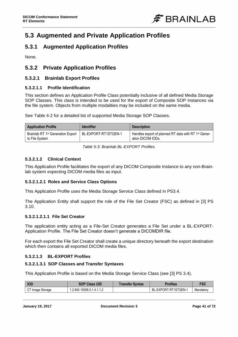
5.3.2.1 Brainlab Export Profiles
5.3.2.1.1 Profile Identification
This section defines an Application Profile Class potentially inclusive of all defined Media Storage SOP Classes. This class is intended to be used for the export of Composite SOP Instances via the file system. Objects from multiple modalities may be included on the same media. See Table 4-2 for a detailed list of supported Media Storage SOP Classes.
Application Profile Identifier Description
Brainlab RT 1st Generation Export to File System
BL-EXPORT-RT1STGEN-1 Handles export of planned RT data with RT 1st Gener-ation DICOM IODs.
Table 5-3: Brainlab BL-EXPORT Profiles.
5.3.2.1.2 Clinical Context
This Application Profile facilitates the export of any DICOM Composite Instance to any non-Brain-lab system expecting DICOM media files as input. 5.3.2.1.2.1 Roles and Service Class Options
This Application Profile uses the Media Storage Service Class defined in PS3.4. The Application Entity shall support the role of the File Set Creator (FSC) as defined in [3] PS 3.10. 5.3.2.1.2.1.1 File Set Creator
The application entity acting as a File-Set Creator generates a File Set under a BL-EXPORT- Application Profile. The File Set Creator doesn’t generate a DICOMDIR file. For each export the File Set Creator shall create a unique directory beneath the export destination which then contains all exported DICOM media files. 5.3.2.1.3 BL-EXPORT Profiles
5.3.2.1.3.1 SOP Classes and Transfer Syntaxes
This Application Profile is based on the Media Storage Service Class (see [3] PS 3.4).
IOD SOP Class UID Transfer Syntax Profiles FSC
CT Image Storage 1.2.840.10008.5.1.4.1.1.2 BL-EXPORT-RT1STGEN-1 Mandatory
DICOM Conformance Statement
RT Elements
Page 42 of 72 Document Revision 3 January 19, 2017
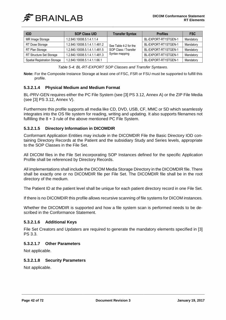
IOD SOP Class UID Transfer Syntax Profiles FSC
MR Image Storage 1.2.840.10008.5.1.4.1.1.4
See Table 4-2 for the SOP Class / Transfer Syntax mapping
BL-EXPORT-RT1STGEN-1 Mandatory
RT Dose Storage 1.2.840.10008.5.1.4.1.1.481.2 BL-EXPORT-RT1STGEN-1 Mandatory
RT Plan Storage 1.2.840.10008.5.1.4.1.1.481.5 BL-EXPORT-RT1STGEN-1 Mandatory
RT Structure Set Storage 1.2.840.10008.5.1.4.1.1.481.3 BL-EXPORT-RT1STGEN-1 Mandatory
Spatial Registration Storage 1.2.840.10008.5.1.4.1.1.66.1 BL-EXPORT-RT1STGEN-1 Mandatory
Table 5-4: BL-RT-EXPORT SOP Classes and Transfer Syntaxes.
Note: For the Composite Instance Storage at least one of FSC, FSR or FSU must be supported to fulfill this profile.
5.3.2.1.4 Physical Medium and Medium Format
BL-PRV-GEN requires either the PC File System (see [3] PS 3.12, Annex A) or the ZIP File Media (see [3] PS 3.12, Annex V). Furthermore this profile supports all media like CD, DVD, USB, CF, MMC or SD which seamlessly integrates into the OS file system for reading, writing and updating. It also supports filenames not fulfilling the 8 + 3 rule of the above mentioned PC File System. 5.3.2.1.5 Directory Information in DICOMDIR
Conformant Application Entities may include in the DICOMDIR File the Basic Directory IOD con-taining Directory Records at the Patient and the subsidiary Study and Series levels, appropriate to the SOP Classes in the File Set. All DICOM files in the File Set incorporating SOP Instances defined for the specific Application Profile shall be referenced by Directory Records. All implementations shall include the DICOM Media Storage Directory in the DICOMDIR file. There shall be exactly one or no DICOMDIR file per File Set. The DICOMDIR file shall be in the root directory of the medium. The Patient ID at the patient level shall be unique for each patient directory record in one File Set. If there is no DICOMDIR this profile allows recursive scanning of file systems for DICOM instances. Whether the DICOMDIR is supported and how a file system scan is performed needs to be de-scribed in the Conformance Statement. 5.3.2.1.6 Additional Keys
File Set Creators and Updaters are required to generate the mandatory elements specified in [3] PS 3.3. 5.3.2.1.7 Other Parameters
Not applicable. 5.3.2.1.8 Security Parameters
Not applicable.
DICOM Conformance Statement RT Elements
January 19, 2017 Document Revision 3 Page 43 of 72
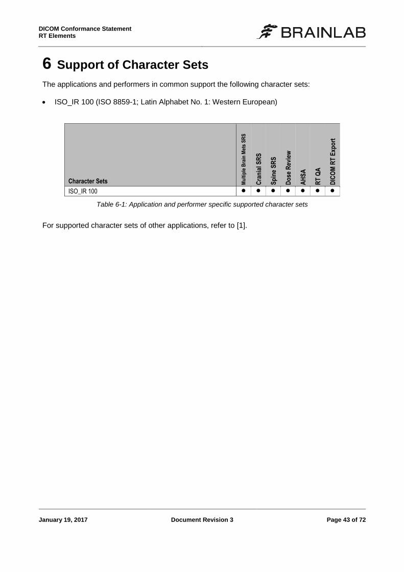
6 Support of Character Sets
The applications and performers in common support the following character sets:
ISO_IR 100 (ISO 8859-1; Latin Alphabet No. 1: Western European)
Character Sets Mu
ltip
le B
rain
Met
s S
RS
Cra
nia
l SR
S
Sp
ine
SR
S
Do
se R
evie
w
AH
SA
RT
QA
DIC
OM
RT
Exp
ort
ISO_IR 100
Table 6-1: Application and performer specific supported character sets
For supported character sets of other applications, refer to [1].

DICOM Conformance Statement RT Elements
January 19, 2017 Document Revision 3 Page 45 of 72
7 Security Profiles
7.1 Security Profiles
None supported
7.2 Association Level Security
None supported.
7.3 Application Level Security
None supported

DICOM Conformance Statement RT Elements
January 19, 2017 Document Revision 3 Page 47 of 72
8 Annexes
8.1 IOD Contents
8.1.1 Supported SOP Instances
8.1.1.1 Secondary Capture Image
See [1].
8.1.1.2 Grayscale Presentation State
See [1].
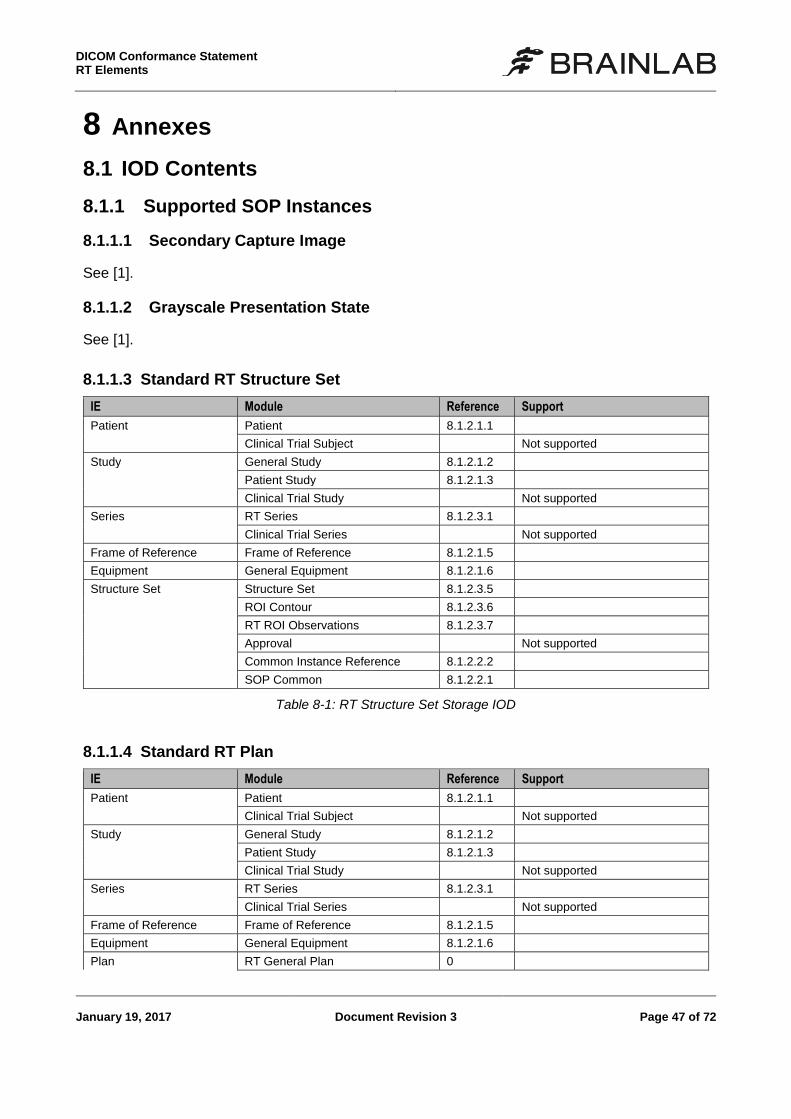
8.1.1.3 Standard RT Structure Set
IE Module Reference Support
Patient Patient 8.1.2.1.1
Clinical Trial Subject Not supported
Study General Study 8.1.2.1.2
Patient Study 8.1.2.1.3
Clinical Trial Study Not supported
Series RT Series 8.1.2.3.1
Clinical Trial Series Not supported
Frame of Reference Frame of Reference 8.1.2.1.5
Equipment General Equipment 8.1.2.1.6
Structure Set Structure Set 8.1.2.3.5
ROI Contour 8.1.2.3.6
RT ROI Observations 8.1.2.3.7
Approval Not supported
Common Instance Reference 8.1.2.2.2
SOP Common 8.1.2.2.1
Table 8-1: RT Structure Set Storage IOD
8.1.1.4 Standard RT Plan
IE Module Reference Support
Patient Patient 8.1.2.1.1
Clinical Trial Subject Not supported
Study General Study 8.1.2.1.2
Patient Study 8.1.2.1.3
Clinical Trial Study Not supported
Series RT Series 8.1.2.3.1
Clinical Trial Series Not supported
Frame of Reference Frame of Reference 8.1.2.1.5
Equipment General Equipment 8.1.2.1.6
Plan RT General Plan 0
DICOM Conformance Statement
RT Elements
Page 48 of 72 Document Revision 3 January 19, 2017
IE Module Reference Support
RT Prescription 8.1.2.3.6
RT Tolerance Tables 8.1.2.3.11
RT Patient Setup 0
RT Fraction Scheme 8.1.2.3.13
RT Beams 8.1.2.3.7
RT Brachy Application Setups
Not supported
Approval 8.1.2.3.8
Common Instance Reference 8.1.2.2.2
SOP Common 8.1.2.2.1
Extended Interface Extended Interface Not always present
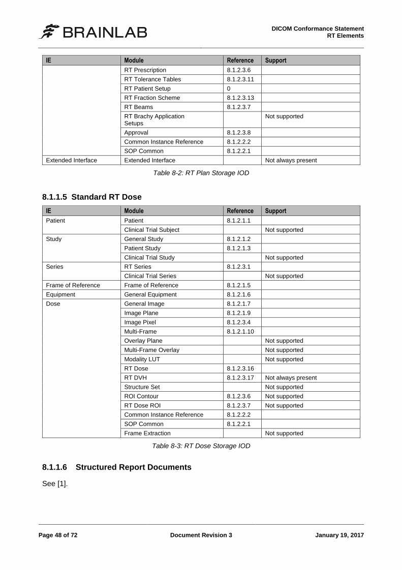
Table 8-2: RT Plan Storage IOD
8.1.1.5 Standard RT Dose
IE Module Reference Support
Patient Patient 8.1.2.1.1
Clinical Trial Subject Not supported
Study General Study 8.1.2.1.2
Patient Study 8.1.2.1.3
Clinical Trial Study Not supported
Series RT Series 8.1.2.3.1
Clinical Trial Series Not supported
Frame of Reference Frame of Reference 8.1.2.1.5
Equipment General Equipment 8.1.2.1.6
Dose General Image 8.1.2.1.7
Image Plane 8.1.2.1.9
Image Pixel 8.1.2.3.4
Multi-Frame 8.1.2.1.10
Overlay Plane Not supported
Multi-Frame Overlay Not supported
Modality LUT Not supported
RT Dose 8.1.2.3.16
RT DVH 8.1.2.3.17 Not always present
Structure Set Not supported
ROI Contour 8.1.2.3.6 Not supported
RT Dose ROI 8.1.2.3.7 Not supported
Common Instance Reference 8.1.2.2.2
SOP Common 8.1.2.2.1
Frame Extraction Not supported
Table 8-3: RT Dose Storage IOD
8.1.1.6 Structured Report Documents
See [1].
DICOM Conformance Statement RT Elements
January 19, 2017 Document Revision 3 Page 49 of 72
8.1.1.7 Spatial Registration
See [1].
8.1.1.8 Segmentation
See [1].
8.1.1.9 Surface Segmentation
See [1].
8.1.1.10 Raw Data
See [1].
8.1.2 Supported Modules
8.1.2.1 Common Composite Image Modules
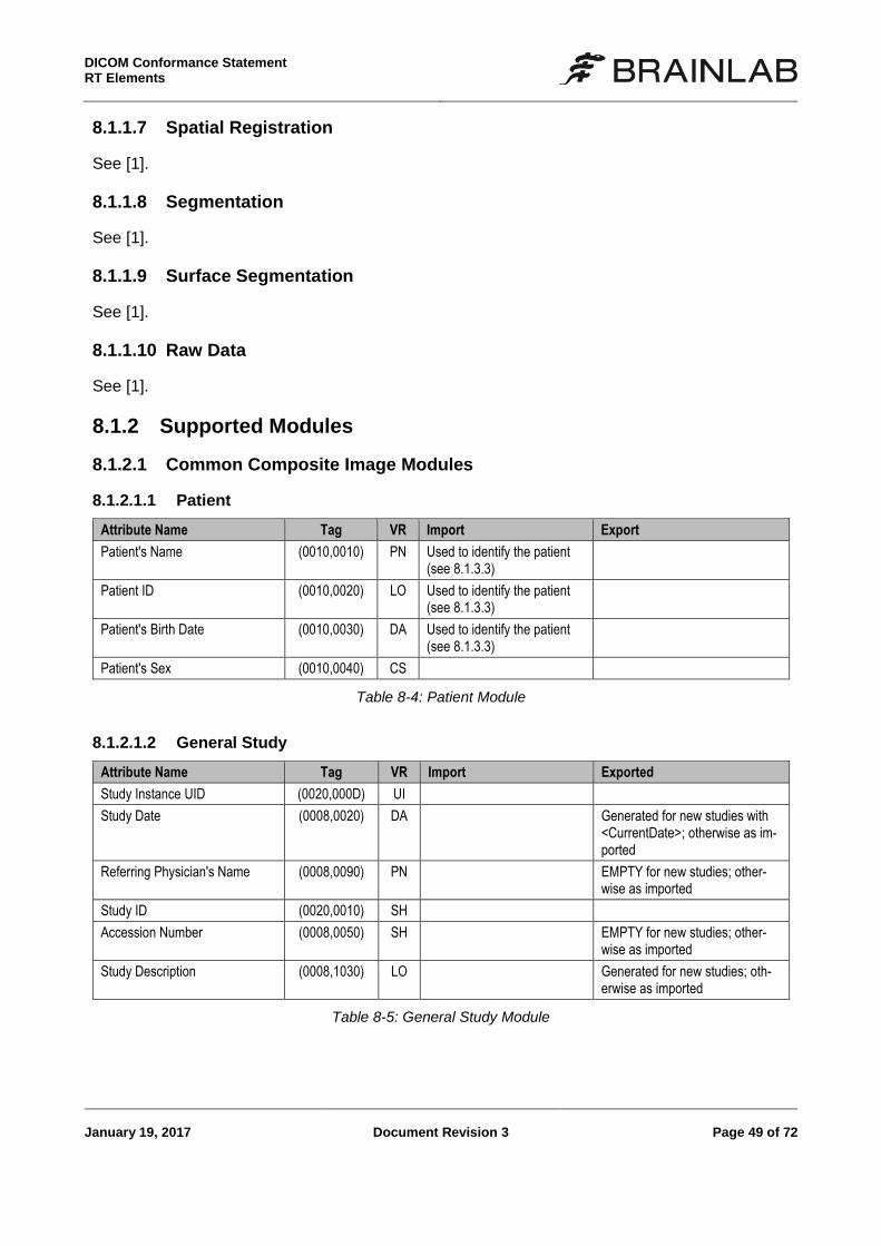
8.1.2.1.1 Patient
Attribute Name Tag VR Import Export
Patient's Name (0010,0010) PN Used to identify the patient (see 8.1.3.3)
Patient ID (0010,0020) LO Used to identify the patient (see 8.1.3.3)
Patient's Birth Date (0010,0030) DA Used to identify the patient (see 8.1.3.3)
Patient's Sex (0010,0040) CS
Table 8-4: Patient Module
8.1.2.1.2 General Study
Attribute Name Tag VR Import Exported
Study Instance UID (0020,000D) UI
Study Date (0008,0020) DA Generated for new studies with <CurrentDate>; otherwise as im-ported
Referring Physician's Name (0008,0090) PN EMPTY for new studies; other-wise as imported
Study ID (0020,0010) SH
Accession Number (0008,0050) SH EMPTY for new studies; other-wise as imported
Study Description (0008,1030) LO Generated for new studies; oth-erwise as imported
Table 8-5: General Study Module
DICOM Conformance Statement
RT Elements
Page 50 of 72 Document Revision 3 January 19, 2017
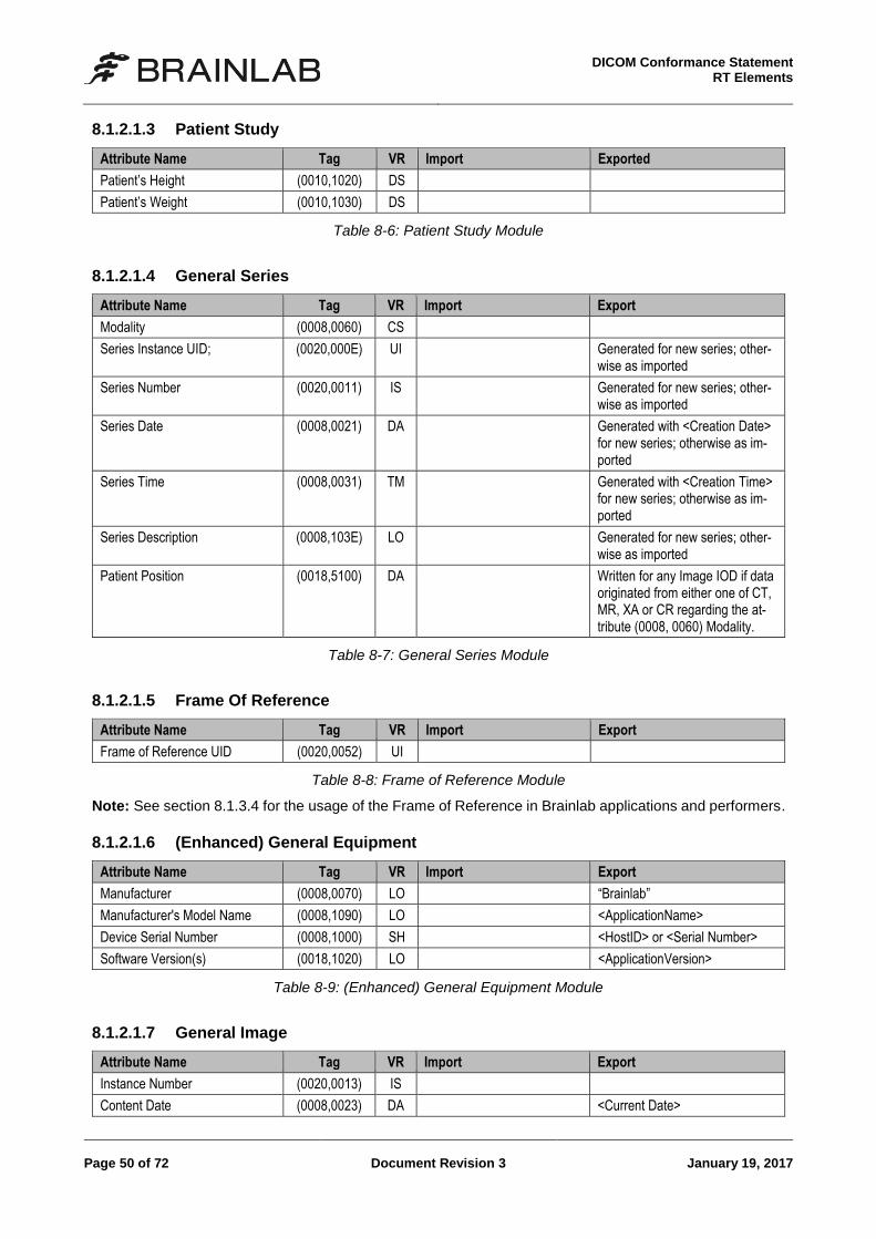
8.1.2.1.3 Patient Study
Attribute Name Tag VR Import Exported
Patient’s Height (0010,1020) DS
Patient’s Weight (0010,1030) DS
Table 8-6: Patient Study Module
8.1.2.1.4 General Series
Attribute Name Tag VR Import Export
Modality (0008,0060) CS
Series Instance UID; (0020,000E) UI Generated for new series; other-wise as imported
Series Number (0020,0011) IS Generated for new series; other-wise as imported
Series Date (0008,0021) DA Generated with <Creation Date> for new series; otherwise as im-ported
Series Time (0008,0031) TM Generated with <Creation Time> for new series; otherwise as im-ported
Series Description (0008,103E) LO Generated for new series; other-wise as imported
Patient Position (0018,5100) DA Written for any Image IOD if data originated from either one of CT, MR, XA or CR regarding the at-tribute (0008, 0060) Modality.
Table 8-7: General Series Module
8.1.2.1.5 Frame Of Reference
Attribute Name Tag VR Import Export
Frame of Reference UID (0020,0052) UI
Table 8-8: Frame of Reference Module
Note: See section 8.1.3.4 for the usage of the Frame of Reference in Brainlab applications and performers.
8.1.2.1.6 (Enhanced) General Equipment
Attribute Name Tag VR Import Export
Manufacturer (0008,0070) LO “Brainlab”
Manufacturer's Model Name (0008,1090) LO <ApplicationName>
Device Serial Number (0008,1000) SH <HostID> or <Serial Number>
Software Version(s) (0018,1020) LO <ApplicationVersion>
Table 8-9: (Enhanced) General Equipment Module
8.1.2.1.7 General Image
Attribute Name Tag VR Import Export
Instance Number (0020,0013) IS
Content Date (0008,0023) DA <Current Date>
DICOM Conformance Statement RT Elements
January 19, 2017 Document Revision 3 Page 51 of 72
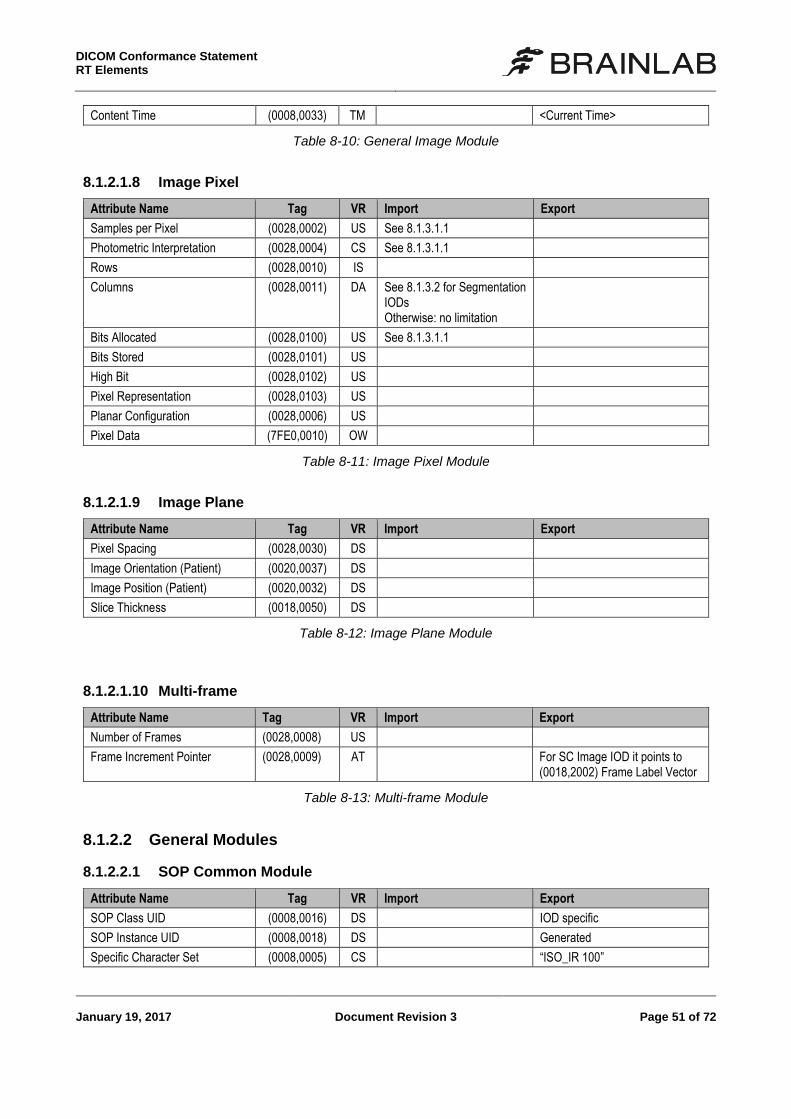
Content Time (0008,0033) TM <Current Time>
Table 8-10: General Image Module
8.1.2.1.8 Image Pixel
Attribute Name Tag VR Import Export
Samples per Pixel (0028,0002) US See 8.1.3.1.1
Photometric Interpretation (0028,0004) CS See 8.1.3.1.1
Rows (0028,0010) IS
Columns (0028,0011) DA See 8.1.3.2 for Segmentation IODs Otherwise: no limitation
Bits Allocated (0028,0100) US See 8.1.3.1.1
Bits Stored (0028,0101) US
High Bit (0028,0102) US
Pixel Representation (0028,0103) US
Planar Configuration (0028,0006) US
Pixel Data (7FE0,0010) OW
Table 8-11: Image Pixel Module
8.1.2.1.9 Image Plane
Attribute Name Tag VR Import Export
Pixel Spacing (0028,0030) DS
Image Orientation (Patient) (0020,0037) DS
Image Position (Patient) (0020,0032) DS
Slice Thickness (0018,0050) DS
Table 8-12: Image Plane Module
8.1.2.1.10 Multi-frame
Attribute Name Tag VR Import Export
Number of Frames (0028,0008) US
Frame Increment Pointer (0028,0009) AT For SC Image IOD it points to (0018,2002) Frame Label Vector
Table 8-13: Multi-frame Module
8.1.2.2 General Modules
8.1.2.2.1 SOP Common Module
Attribute Name Tag VR Import Export
SOP Class UID (0008,0016) DS IOD specific
SOP Instance UID (0008,0018) DS Generated
Specific Character Set (0008,0005) CS “ISO_IR 100”
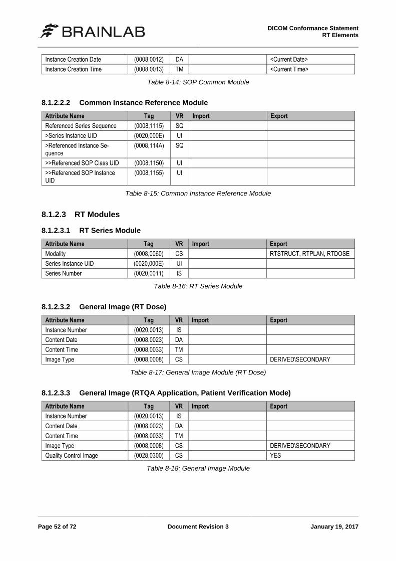
DICOM Conformance Statement
RT Elements
Page 52 of 72 Document Revision 3 January 19, 2017
Instance Creation Date (0008,0012) DA <Current Date>
Instance Creation Time (0008,0013) TM <Current Time>
Table 8-14: SOP Common Module
8.1.2.2.2 Common Instance Reference Module
Attribute Name Tag VR Import Export
Referenced Series Sequence (0008,1115) SQ
>Series Instance UID (0020,000E) UI
>Referenced Instance Se-quence
(0008,114A) SQ
>>Referenced SOP Class UID (0008,1150) UI
>>Referenced SOP Instance UID
(0008,1155) UI
Table 8-15: Common Instance Reference Module
8.1.2.3 RT Modules
8.1.2.3.1 RT Series Module
Attribute Name Tag VR Import Export
Modality (0008,0060) CS RTSTRUCT, RTPLAN, RTDOSE
Series Instance UID (0020,000E) UI
Series Number (0020,0011) IS
Table 8-16: RT Series Module
8.1.2.3.2 General Image (RT Dose)
Attribute Name Tag VR Import Export
Instance Number (0020,0013) IS
Content Date (0008,0023) DA
Content Time (0008,0033) TM
Image Type (0008,0008) CS DERIVED\SECONDARY
Table 8-17: General Image Module (RT Dose)
8.1.2.3.3 General Image (RTQA Application, Patient Verification Mode)
Attribute Name Tag VR Import Export
Instance Number (0020,0013) IS
Content Date (0008,0023) DA
Content Time (0008,0033) TM
Image Type (0008,0008) CS DERIVED\SECONDARY
Quality Control Image (0028,0300) CS YES
Table 8-18: General Image Module
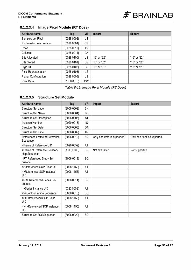
DICOM Conformance Statement RT Elements
January 19, 2017 Document Revision 3 Page 53 of 72
8.1.2.3.4 Image Pixel Module (RT Dose)
Attribute Name Tag VR Import Export
Samples per Pixel (0028,0002) US
Photometric Interpretation (0028,0004) CS
Rows (0028,0010) IS
Columns (0028,0011) DA
Bits Allocated (0028,0100) US “16” or “32” “16” or “32”
Bits Stored (0028,0101) US “16” or “32” “16” or “32”
High Bit (0028,0102) US “15” or “31” “15” or “31”
Pixel Representation (0028,0103) US
Planar Configuration (0028,0006) US
Pixel Data (7FE0,0010) OW
Table 8-19: Image Pixel Module (RT Dose)
8.1.2.3.5 Structure Set Module
Attribute Name Tag VR Import Export
Structure Set Label (3006,0002) SH
Structure Set Name (3006,0004) LO
Structure Set Description (3006,0006) ST
Instance Number (0020,0013) IS
Structure Set Date (3006,0008) DA
Structure Set Time (3006,0009) TM
Referenced Frame of Reference Sequence
(3006,0010) SQ Only one Item is supported. Only one Item is supported.
>Frame of Reference UID (0020,0052) UI
>Frame of Reference Relation-ship Sequence
(3006,00C0) SQ Not evaluated. Not supported.
>RT Referenced Study Se-quence
(3006,0012) SQ
>>Referenced SOP Class UID (0008,1150) UI
>>Referenced SOP Instance UID
(0008,1155) UI
>>RT Referenced Series Se-quence
(3006,0014) SQ
>>Series Instance UID (0020,000E) UI
>>>Contour Image Sequence (3006,0016) SQ
>>>>Referenced SOP Class UID
(0008,1150) UI
>>>>Referenced SOP Instance UID
(0008,1155) UI
Structure Set ROI Sequence (3006,0020) SQ
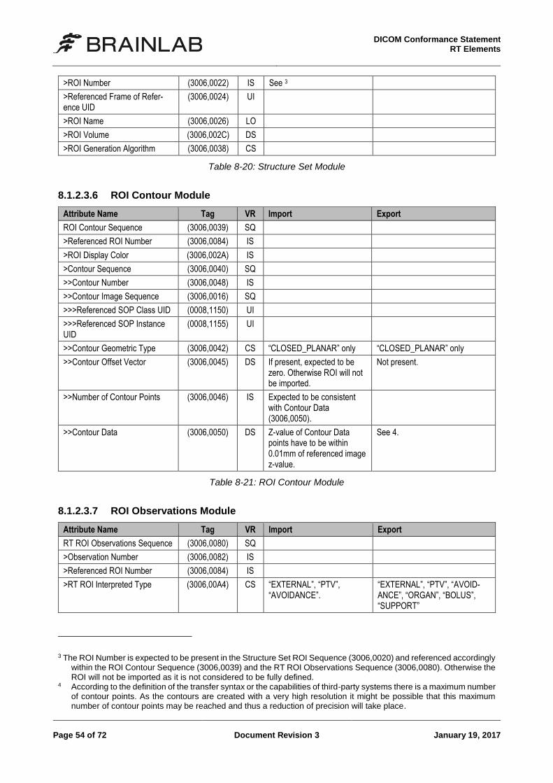
DICOM Conformance Statement
RT Elements
Page 54 of 72 Document Revision 3 January 19, 2017
>ROI Number (3006,0022) IS See 3
>Referenced Frame of Refer-ence UID
(3006,0024) UI
>ROI Name (3006,0026) LO
>ROI Volume (3006,002C) DS
>ROI Generation Algorithm (3006,0038) CS
Table 8-20: Structure Set Module
8.1.2.3.6 ROI Contour Module
Attribute Name Tag VR Import Export
ROI Contour Sequence (3006,0039) SQ
>Referenced ROI Number (3006,0084) IS
>ROI Display Color (3006,002A) IS
>Contour Sequence (3006,0040) SQ
>>Contour Number (3006,0048) IS
>>Contour Image Sequence (3006,0016) SQ
>>>Referenced SOP Class UID (0008,1150) UI
>>>Referenced SOP Instance UID
(0008,1155) UI
>>Contour Geometric Type (3006,0042) CS “CLOSED_PLANAR” only “CLOSED_PLANAR” only
>>Contour Offset Vector (3006,0045) DS If present, expected to be zero. Otherwise ROI will not be imported.
Not present.
>>Number of Contour Points (3006,0046) IS Expected to be consistent with Contour Data (3006,0050).
>>Contour Data (3006,0050) DS Z-value of Contour Data points have to be within 0.01mm of referenced image z-value.
See 4.
Table 8-21: ROI Contour Module
8.1.2.3.7 ROI Observations Module
Attribute Name Tag VR Import Export
RT ROI Observations Sequence (3006,0080) SQ
>Observation Number (3006,0082) IS
>Referenced ROI Number (3006,0084) IS
>RT ROI Interpreted Type (3006,00A4) CS “EXTERNAL”, “PTV”, “AVOIDANCE”.
“EXTERNAL”, “PTV”, “AVOID-ANCE”, “ORGAN”, “BOLUS”, “SUPPORT”
3 The ROI Number is expected to be present in the Structure Set ROI Sequence (3006,0020) and referenced accordingly
within the ROI Contour Sequence (3006,0039) and the RT ROI Observations Sequence (3006,0080). Otherwise the ROI will not be imported as it is not considered to be fully defined.
4 According to the definition of the transfer syntax or the capabilities of third-party systems there is a maximum number of contour points. As the contours are created with a very high resolution it might be possible that this maximum number of contour points may be reached and thus a reduction of precision will take place.
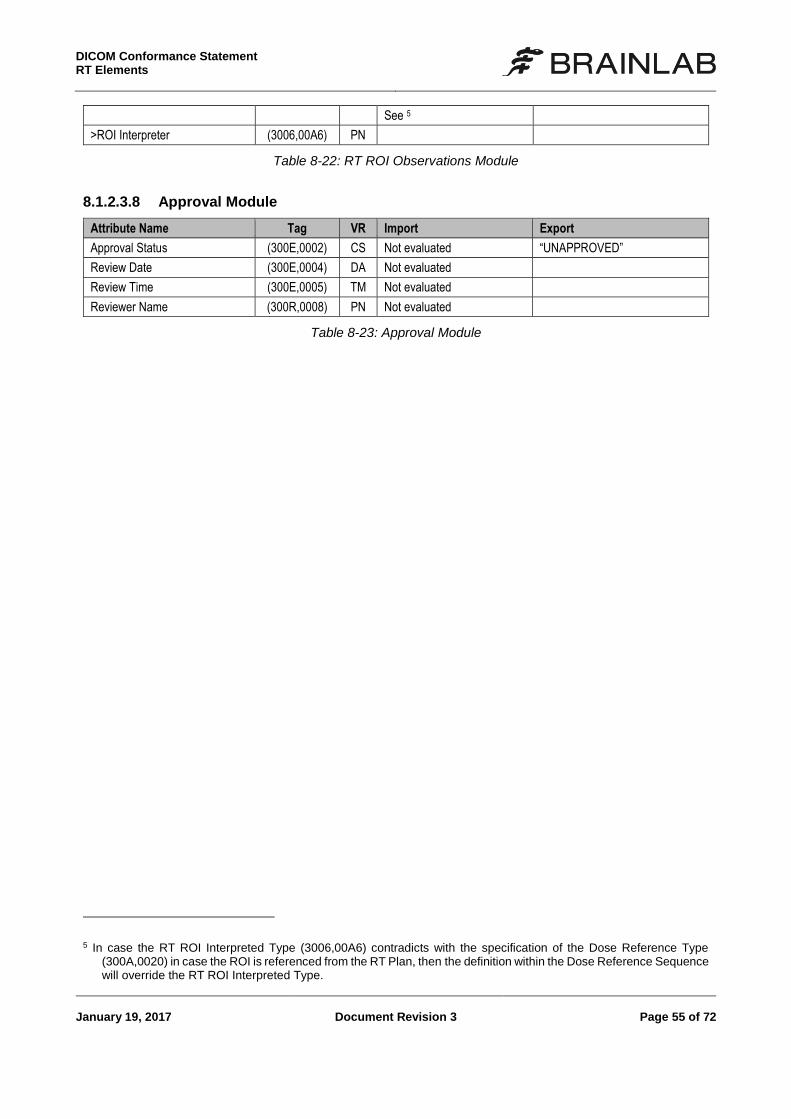
DICOM Conformance Statement RT Elements
January 19, 2017 Document Revision 3 Page 55 of 72
See 5
>ROI Interpreter (3006,00A6) PN
Table 8-22: RT ROI Observations Module
8.1.2.3.8 Approval Module
Attribute Name Tag VR Import Export
Approval Status (300E,0002) CS Not evaluated “UNAPPROVED”
Review Date (300E,0004) DA Not evaluated
Review Time (300E,0005) TM Not evaluated
Reviewer Name (300R,0008) PN Not evaluated
Table 8-23: Approval Module
5 In case the RT ROI Interpreted Type (3006,00A6) contradicts with the specification of the Dose Reference Type
(300A,0020) in case the ROI is referenced from the RT Plan, then the definition within the Dose Reference Sequence will override the RT ROI Interpreted Type.
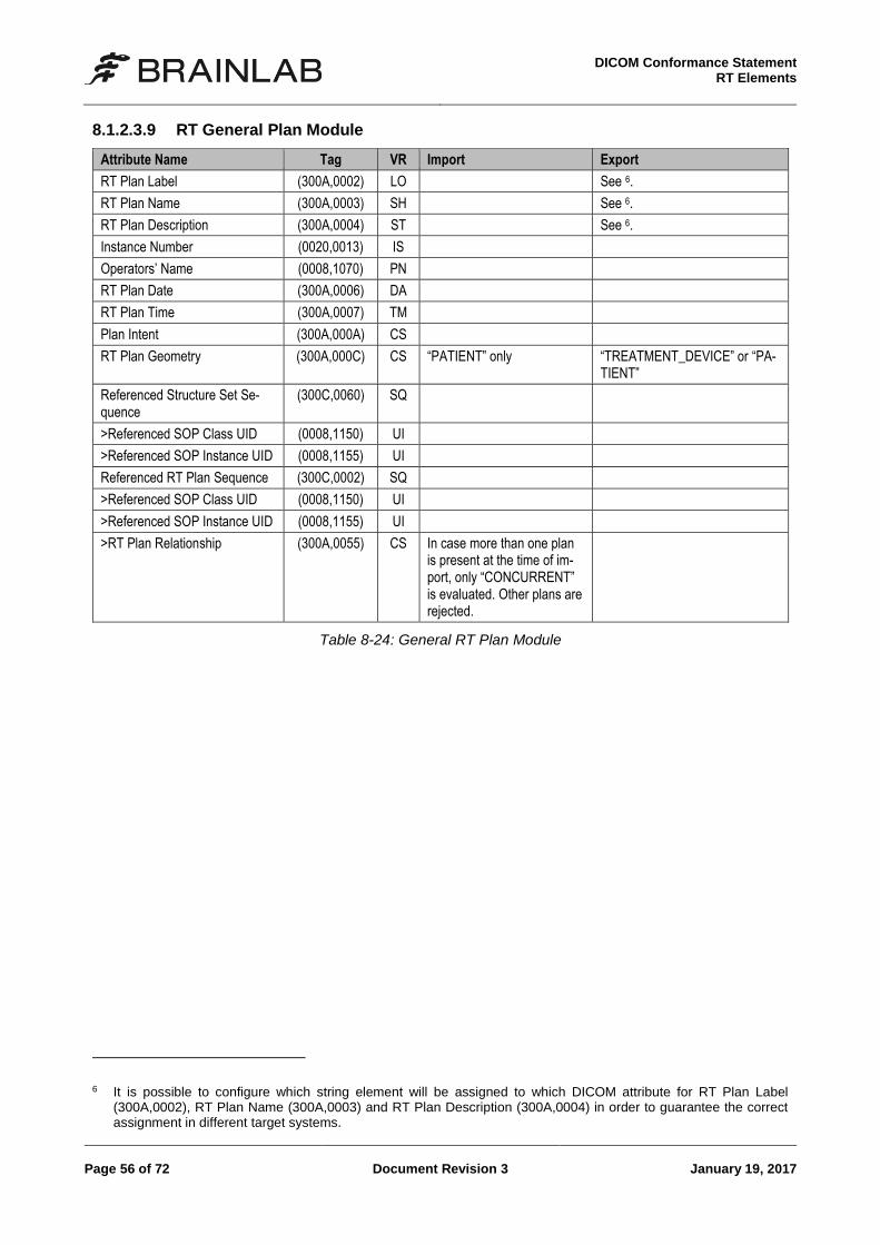
DICOM Conformance Statement
RT Elements
Page 56 of 72 Document Revision 3 January 19, 2017
8.1.2.3.9 RT General Plan Module
Attribute Name Tag VR Import Export
RT Plan Label (300A,0002) LO See 6.
RT Plan Name (300A,0003) SH See 6.
RT Plan Description (300A,0004) ST See 6.
Instance Number (0020,0013) IS
Operators’ Name (0008,1070) PN
RT Plan Date (300A,0006) DA
RT Plan Time (300A,0007) TM
Plan Intent (300A,000A) CS
RT Plan Geometry (300A,000C) CS “PATIENT” only “TREATMENT_DEVICE” or “PA-TIENT”
Referenced Structure Set Se-quence
(300C,0060) SQ
>Referenced SOP Class UID (0008,1150) UI
>Referenced SOP Instance UID (0008,1155) UI
Referenced RT Plan Sequence (300C,0002) SQ
>Referenced SOP Class UID (0008,1150) UI
>Referenced SOP Instance UID (0008,1155) UI
>RT Plan Relationship (300A,0055) CS In case more than one plan is present at the time of im-port, only “CONCURRENT” is evaluated. Other plans are rejected.
Table 8-24: General RT Plan Module
6 It is possible to configure which string element will be assigned to which DICOM attribute for RT Plan Label
(300A,0002), RT Plan Name (300A,0003) and RT Plan Description (300A,0004) in order to guarantee the correct assignment in different target systems.
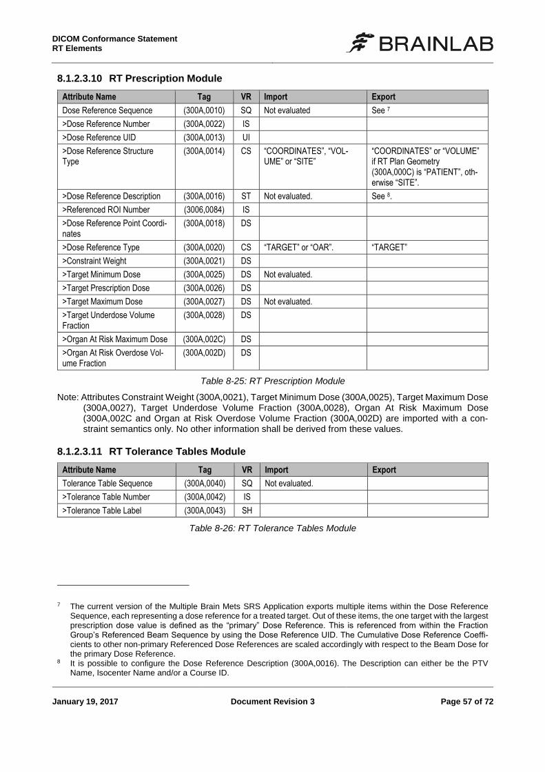
DICOM Conformance Statement RT Elements
January 19, 2017 Document Revision 3 Page 57 of 72
8.1.2.3.10 RT Prescription Module
Attribute Name Tag VR Import Export
Dose Reference Sequence (300A,0010) SQ Not evaluated See 7
>Dose Reference Number (300A,0022) IS
>Dose Reference UID (300A,0013) UI
>Dose Reference Structure Type
(300A,0014) CS “COORDINATES”, “VOL-UME” or “SITE”
“COORDINATES” or “VOLUME” if RT Plan Geometry (300A,000C) is “PATIENT”, oth-erwise “SITE”.
>Dose Reference Description (300A,0016) ST Not evaluated. See 8.
>Referenced ROI Number (3006,0084) IS
>Dose Reference Point Coordi-nates
(300A,0018) DS
>Dose Reference Type (300A,0020) CS “TARGET” or “OAR”. “TARGET”
>Constraint Weight (300A,0021) DS
>Target Minimum Dose (300A,0025) DS Not evaluated.
>Target Prescription Dose (300A,0026) DS
>Target Maximum Dose (300A,0027) DS Not evaluated.
>Target Underdose Volume Fraction
(300A,0028) DS
>Organ At Risk Maximum Dose (300A,002C) DS
>Organ At Risk Overdose Vol-ume Fraction
(300A,002D) DS
Table 8-25: RT Prescription Module
Note: Attributes Constraint Weight (300A,0021), Target Minimum Dose (300A,0025), Target Maximum Dose (300A,0027), Target Underdose Volume Fraction (300A,0028), Organ At Risk Maximum Dose (300A,002C and Organ at Risk Overdose Volume Fraction (300A,002D) are imported with a con-straint semantics only. No other information shall be derived from these values.
8.1.2.3.11 RT Tolerance Tables Module
Attribute Name Tag VR Import Export
Tolerance Table Sequence (300A,0040) SQ Not evaluated.
>Tolerance Table Number (300A,0042) IS
>Tolerance Table Label (300A,0043) SH
Table 8-26: RT Tolerance Tables Module
7 The current version of the Multiple Brain Mets SRS Application exports multiple items within the Dose Reference
Sequence, each representing a dose reference for a treated target. Out of these items, the one target with the largest prescription dose value is defined as the “primary” Dose Reference. This is referenced from within the Fraction Group’s Referenced Beam Sequence by using the Dose Reference UID. The Cumulative Dose Reference Coeffi-cients to other non-primary Referenced Dose References are scaled accordingly with respect to the Beam Dose for the primary Dose Reference.
8 It is possible to configure the Dose Reference Description (300A,0016). The Description can either be the PTV Name, Isocenter Name and/or a Course ID.
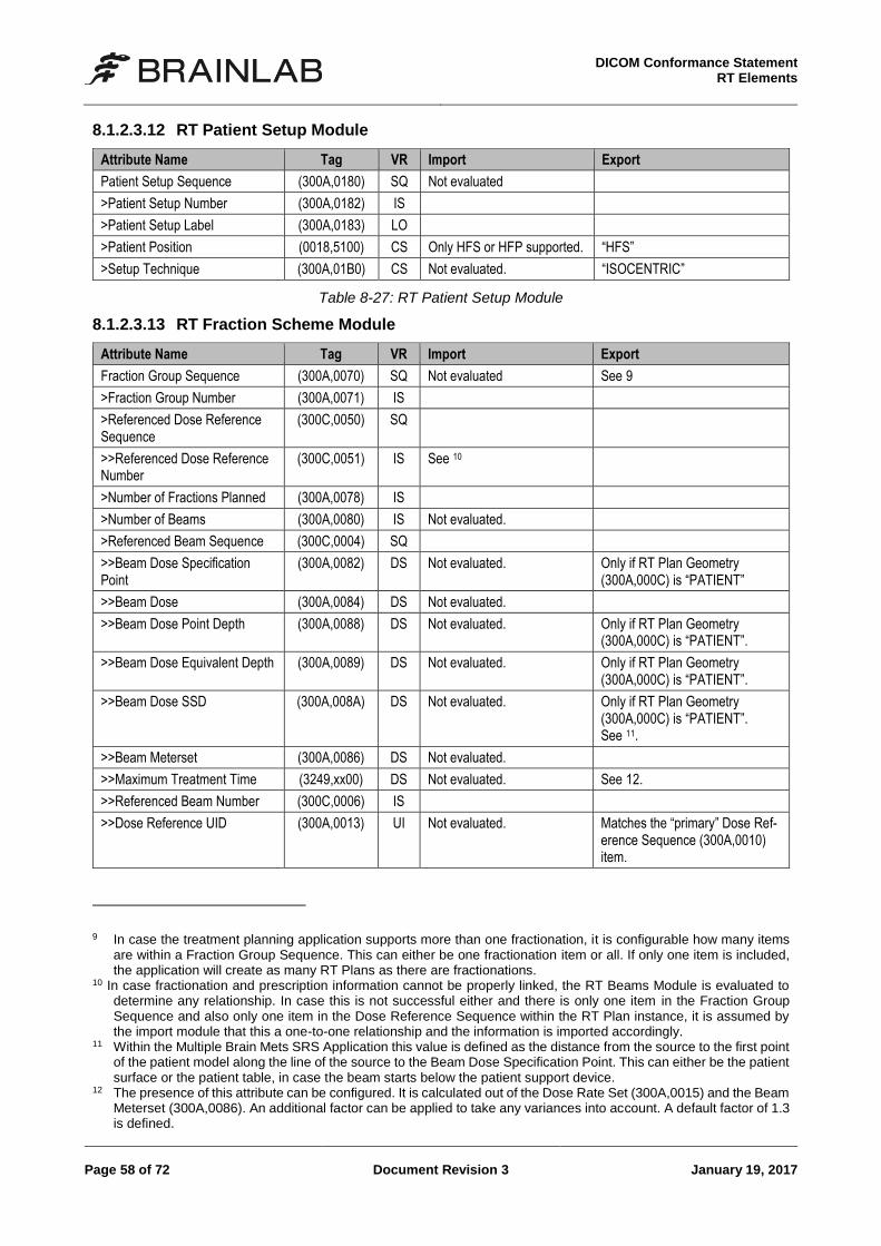
DICOM Conformance Statement
RT Elements
Page 58 of 72 Document Revision 3 January 19, 2017
8.1.2.3.12 RT Patient Setup Module
Attribute Name Tag VR Import Export
Patient Setup Sequence (300A,0180) SQ Not evaluated
>Patient Setup Number (300A,0182) IS
>Patient Setup Label (300A,0183) LO
>Patient Position (0018,5100) CS Only HFS or HFP supported. “HFS”
>Setup Technique (300A,01B0) CS Not evaluated. “ISOCENTRIC”
Table 8-27: RT Patient Setup Module
8.1.2.3.13 RT Fraction Scheme Module
Attribute Name Tag VR Import Export
Fraction Group Sequence (300A,0070) SQ Not evaluated See 9
>Fraction Group Number (300A,0071) IS
>Referenced Dose Reference Sequence
(300C,0050) SQ
>>Referenced Dose Reference Number
(300C,0051) IS See 10
>Number of Fractions Planned (300A,0078) IS
>Number of Beams (300A,0080) IS Not evaluated.
>Referenced Beam Sequence (300C,0004) SQ
>>Beam Dose Specification Point
(300A,0082) DS Not evaluated. Only if RT Plan Geometry (300A,000C) is “PATIENT”
>>Beam Dose (300A,0084) DS Not evaluated.
>>Beam Dose Point Depth (300A,0088) DS Not evaluated. Only if RT Plan Geometry (300A,000C) is “PATIENT”.
>>Beam Dose Equivalent Depth (300A,0089) DS Not evaluated. Only if RT Plan Geometry (300A,000C) is “PATIENT”.
>>Beam Dose SSD (300A,008A) DS Not evaluated. Only if RT Plan Geometry (300A,000C) is “PATIENT”. See 11.
>>Beam Meterset (300A,0086) DS Not evaluated.
>>Maximum Treatment Time (3249,xx00) DS Not evaluated. See 12.
>>Referenced Beam Number (300C,0006) IS
>>Dose Reference UID (300A,0013) UI Not evaluated. Matches the “primary” Dose Ref-erence Sequence (300A,0010) item.
9 In case the treatment planning application supports more than one fractionation, it is configurable how many items
are within a Fraction Group Sequence. This can either be one fractionation item or all. If only one item is included, the application will create as many RT Plans as there are fractionations.
10 In case fractionation and prescription information cannot be properly linked, the RT Beams Module is evaluated to determine any relationship. In case this is not successful either and there is only one item in the Fraction Group Sequence and also only one item in the Dose Reference Sequence within the RT Plan instance, it is assumed by the import module that this a one-to-one relationship and the information is imported accordingly.
11 Within the Multiple Brain Mets SRS Application this value is defined as the distance from the source to the first point of the patient model along the line of the source to the Beam Dose Specification Point. This can either be the patient surface or the patient table, in case the beam starts below the patient support device.
12 The presence of this attribute can be configured. It is calculated out of the Dose Rate Set (300A,0015) and the Beam Meterset (300A,0086). An additional factor can be applied to take any variances into account. A default factor of 1.3 is defined.
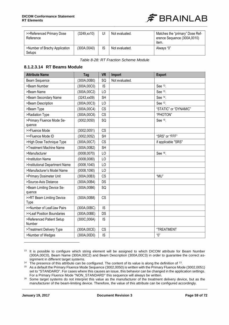
DICOM Conformance Statement RT Elements
January 19, 2017 Document Revision 3 Page 59 of 72
>>Referenced Primary Dose Reference
(3249,xx10) UI Not evaluated. Matches the “primary” Dose Ref-erence Sequence (300A,0010) item.
>Number of Brachy Application Setups
(300A,00A0) IS Not evaluated. Always “0”
Table 8-28: RT Fraction Scheme Module
8.1.2.3.14 RT Beams Module
Attribute Name Tag VR Import Export
Beam Sequence (300A,00B0) SQ Not evaluated.
>Beam Number (300A,00C0) IS See 13.
>Beam Name (300A,00C2) LO See 13.
>Beam Secondary Name (3243,xx09) SH See 14.
>Beam Description (300A,00C3) LO See 13.
>Beam Type (300A,00C4) CS “STATIC” or “DYNAMIC”
>Radiation Type (300A,00C6) CS “PHOTON”
>Primary Fluence Mode Se-quence
(3002,0050) SQ See 15.
>>Fluence Mode (3002,0051) CS
>>Fluence Mode ID (3002,0052) SH “SRS” or “FFF”
>High Dose Technique Type (300A,00C7) CS if applicable "SRS"
>Treatment Machine Name (300A,00B2) SH
>Manufacturer (0008,0070) LO See 16.
>Institution Name (0008,0080) LO
>Institutional Department Name (0008,1040) LO
>Manufacturer’s Model Name (0008,1090) LO
>Primary Dosimeter Unit (300A,00B3) CS “MU”
>Source-Axis Distance (300A,00B4) DS
>Beam Limiting Device Se-quence
(300A,00B6) SQ
>>RT Beam Limiting Device Type
(300A,00B8) CS
>>Number of Leaf/Jaw Pairs (300A,00BC) IS
>>Leaf Position Boundaries (300A,00BE) DS
>Referenced Patient Setup Number
(300C,006A) IS
>Treatment Delivery Type (300A,00CE) CS “TREATMENT
>Number of Wedges (300A,00D0) IS “0”
13 It is possible to configure which string element will be assigned to which DICOM attribute for Beam Number
(300A,00C0), Beam Name (300A,00C2) and Beam Description (300A,00C3) in order to guarantee the correct as-signment in different target systems.
14 The presence of this attribute can be configured. The content of its value is along the definition of 13. 15 As a default the Primary Fluence Mode Sequence (3002,0050) is written with the Primary Fluence Mode (3002,0051)
set to "STANDARD". For cases where this causes an issue, this behavior can be changed in the application settings. For a Primary Fluence Mode "NON_STANDARD" this sequence will always be written.
16 Some target systems do not interpret this value as the manufacturer of the treatment delivery device, but as the manufacturer of the beam-limiting device. Therefore, the value of this attribute can be configured accordingly.
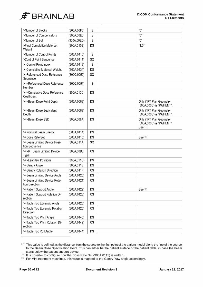
DICOM Conformance Statement
RT Elements
Page 60 of 72 Document Revision 3 January 19, 2017
>Number of Blocks (300A,00F0) IS “0”
>Number of Compensators (300A,00E0) IS “0”
>Number of Boli (300A,00ED) IS “0”
>Final Cumulative Meterset Weight
(300A,010E) DS “1.0”
>Number of Control Points (300A,0110) IS
>Control Point Sequence (300A,0111) SQ
>>Control Point Index (300A,0112) IS
>>Cumulative Meterset Weight (300A,0134) DS
>>Referenced Dose Reference Sequence
(300C,0050) SQ
>>>Referenced Dose Reference Number
(300C,0051) IS
>>>Cumulative Dose Reference Coefficient
(300A,010C) DS
>>>Beam Dose Point Depth (300A,0088) DS Only if RT Plan Geometry (300A,000C) is “PATIENT”.
>>>Beam Dose Equivalent Depth
(300A,0089) DS Only if RT Plan Geometry (300A,000C) is “PATIENT”.
>>>Beam Dose SSD (300A,008A) DS Only if RT Plan Geometry (300A,000C) is “PATIENT”. See 17.
>>Nominal Beam Energy (300A,0114) DS
>>Dose Rate Set (300A,0115) DS See 18.
>>Beam Limiting Device Posi-tion Sequence
(300A,011A) SQ
>>>RT Beam Limiting Device Type
(300A,00B8) CS
>>>Leaf/Jaw Positions (300A,011C) DS
>>Gantry Angle (300A,011E) DS
>>Gantry Rotation Direction (300A,011F) CS
>>Beam Limiting Device Angle (300A,0120) DS
>>Beam Limiting Device Rota-tion Direction
(300A,0121) CS
>>Patient Support Angle (300A,0122) DS See 19.
>>Patient Support Rotation Di-rection
(300A,0123) CS
>>Table Top Eccentric Angle (300A,0125) DS
>>Table Top Eccentric Rotation Direction
(300A,0126) CS
>>Table Top Pitch Angle (300A,0140) DS
>>Table Top Pitch Rotation Di-rection
(300A,0142) CS
>>Table Top Roll Angle (300A,0144) DS
17 This value is defined as the distance from the source to the first point of the patient model along the line of the source
to the Beam Dose Specification Point. This can either be the patient surface or the patient table, in case the beam starts below the patient support device.
18 It is possible to configure how the Dose Rate Set (300A,0115) is written. 19 For MHI treatment machines, this value is mapped to the Gantry Yaw angle accordingly.
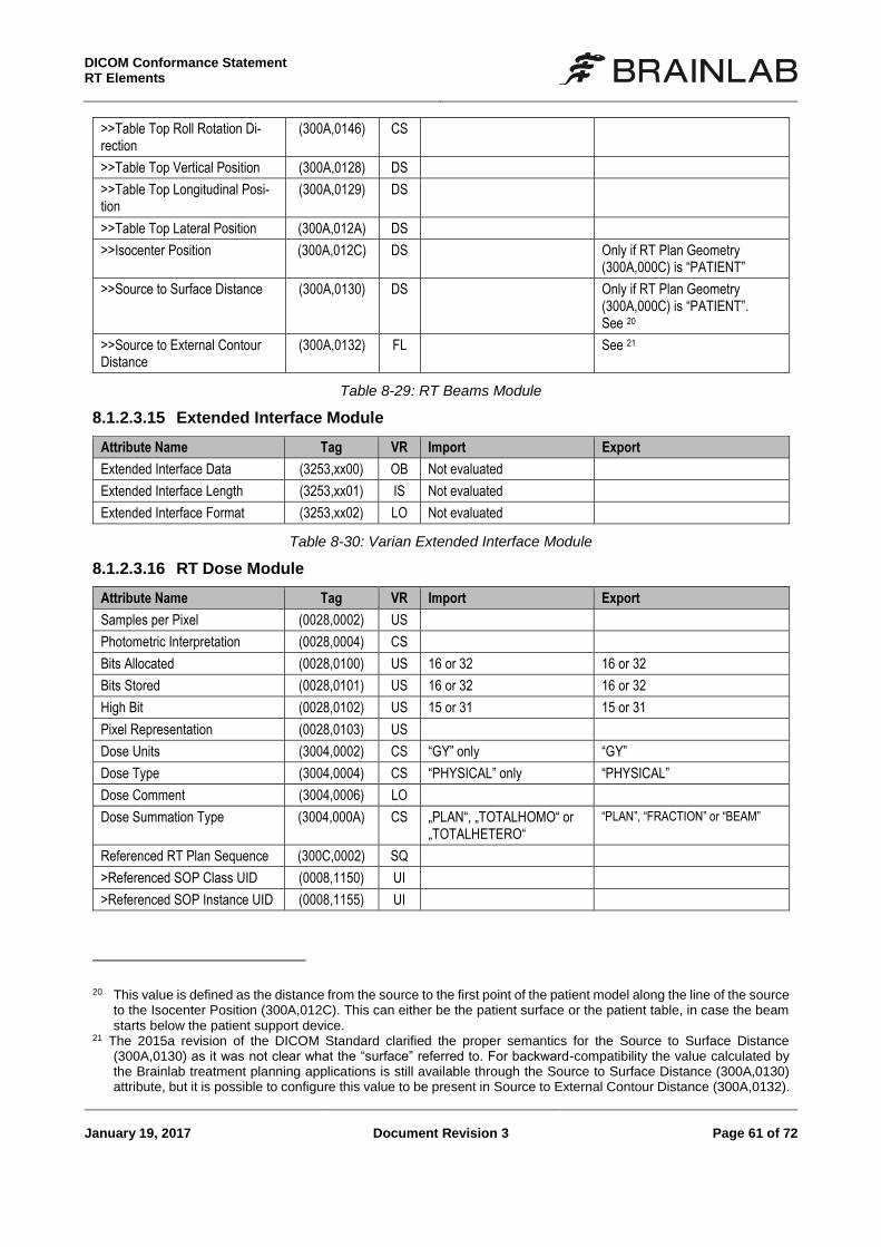
DICOM Conformance Statement RT Elements
January 19, 2017 Document Revision 3 Page 61 of 72
>>Table Top Roll Rotation Di-rection
(300A,0146) CS
>>Table Top Vertical Position (300A,0128) DS
>>Table Top Longitudinal Posi-tion
(300A,0129) DS
>>Table Top Lateral Position (300A,012A) DS
>>Isocenter Position (300A,012C) DS Only if RT Plan Geometry (300A,000C) is “PATIENT”
>>Source to Surface Distance (300A,0130) DS Only if RT Plan Geometry (300A,000C) is “PATIENT”. See 20
>>Source to External Contour Distance
(300A,0132) FL See 21
Table 8-29: RT Beams Module
8.1.2.3.15 Extended Interface Module
Attribute Name Tag VR Import Export
Extended Interface Data (3253,xx00) OB Not evaluated
Extended Interface Length (3253,xx01) IS Not evaluated
Extended Interface Format (3253,xx02) LO Not evaluated
Table 8-30: Varian Extended Interface Module
8.1.2.3.16 RT Dose Module
Attribute Name Tag VR Import Export
Samples per Pixel (0028,0002) US
Photometric Interpretation (0028,0004) CS
Bits Allocated (0028,0100) US 16 or 32 16 or 32
Bits Stored (0028,0101) US 16 or 32 16 or 32
High Bit (0028,0102) US 15 or 31 15 or 31
Pixel Representation (0028,0103) US
Dose Units (3004,0002) CS “GY” only “GY”
Dose Type (3004,0004) CS “PHYSICAL” only “PHYSICAL”
Dose Comment (3004,0006) LO
Dose Summation Type (3004,000A) CS „PLAN“, „TOTALHOMO“ or „TOTALHETERO“
“PLAN”, “FRACTION” or “BEAM”
Referenced RT Plan Sequence (300C,0002) SQ
>Referenced SOP Class UID (0008,1150) UI
>Referenced SOP Instance UID (0008,1155) UI
20 This value is defined as the distance from the source to the first point of the patient model along the line of the source
to the Isocenter Position (300A,012C). This can either be the patient surface or the patient table, in case the beam starts below the patient support device.
21 The 2015a revision of the DICOM Standard clarified the proper semantics for the Source to Surface Distance (300A,0130) as it was not clear what the “surface” referred to. For backward-compatibility the value calculated by the Brainlab treatment planning applications is still available through the Source to Surface Distance (300A,0130) attribute, but it is possible to configure this value to be present in Source to External Contour Distance (300A,0132).
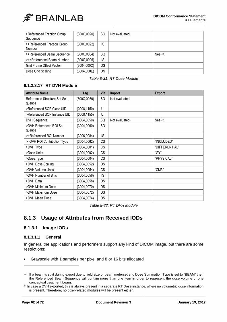
DICOM Conformance Statement
RT Elements
Page 62 of 72 Document Revision 3 January 19, 2017
>Referenced Fraction Group Sequence
(300C,0020) SQ Not evaluated.
>>Referenced Fraction Group Number
(300C,0022) IS
>>Referenced Beam Sequence (300C,0004) SQ See 22.
>>>Referenced Beam Number (300C,0006) IS
Grid Frame Offset Vector (3004,000C) DS
Dose Grid Scaling (3004,000E) DS
Table 8-31: RT Dose Module
8.1.2.3.17 RT DVH Module
Attribute Name Tag VR Import Export
Referenced Structure Set Se-quence
(300C,0060) SQ Not evaluated.
>Referenced SOP Class UID (0008,1150) UI
>Referenced SOP Instance UID (0008,1155) UI
DVH Sequence (3004,0050) SQ Not evaluated. See 23
>DVH Referenced ROI Se-quence
(3004,0060) SQ
>>Referenced ROI Number (3006,0084) IS
>>DVH ROI Contribution Type (3004,0062) CS “INCLUDED”
>DVH Type (3004,0001) CS “DIFFERENTIAL”
>Dose Units (3004,0002) CS “GY”
>Dose Type (3004,0004) CS “PHYSICAL”
>DVH Dose Scaling (3004,0052) DS
>DVH Volume Units (3004,0054) CS “CM3”
>DVH Number of Bins (3004,0056) IS
>DVH Data (3004,0058) DS
>DVH Minimum Dose (3004,0070) DS
>DVH Maximum Dose (3004,0072) DS
>DVH Mean Dose (3004,0074) DS
Table 8-32: RT DVH Module
8.1.3 Usage of Attributes from Received IODs
8.1.3.1 Image IODs
8.1.3.1.1 General
In general the applications and performers support any kind of DICOM image, but there are some restrictions:
Grayscale with 1 samples per pixel and 8 or 16 bits allocated
22 If a beam is split during export due to field size or beam meterset and Dose Summation Type is set to “BEAM” then
the Referenced Beam Sequence will contain more than one item in order to represent the dose volume of one conceptual treatment beam.
23 In case a DVH exported, this is always present in a separate RT Dose instance, where no volumetric dose information is present. Therefore, no pixel-related modules will be present either.
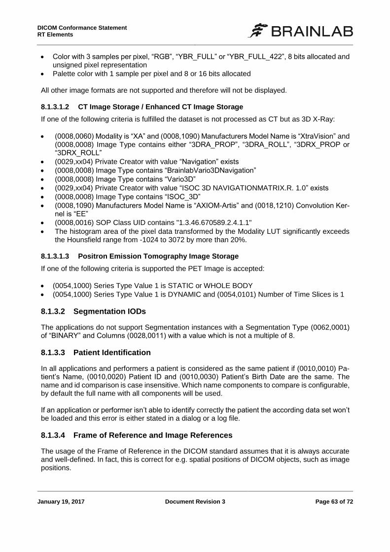
DICOM Conformance Statement RT Elements
January 19, 2017 Document Revision 3 Page 63 of 72
Color with 3 samples per pixel, “RGB”, “YBR_FULL” or “YBR_FULL_422”, 8 bits allocated and unsigned pixel representation
Palette color with 1 sample per pixel and 8 or 16 bits allocated All other image formats are not supported and therefore will not be displayed. 8.1.3.1.2 CT Image Storage / Enhanced CT Image Storage
If one of the following criteria is fulfilled the dataset is not processed as CT but as 3D X-Ray:
(0008,0060) Modality is “XA” and (0008,1090) Manufacturers Model Name is “XtraVision” and (0008,0008) Image Type contains either “3DRA_PROP”, “3DRA_ROLL”, “3DRX_PROP or “3DRX_ROLL”
(0029,xx04) Private Creator with value “Navigation” exists
(0008,0008) Image Type contains “BrainlabVario3DNavigation”
(0008,0008) Image Type contains “Vario3D”
(0029,xx04) Private Creator with value “ISOC 3D NAVIGATIONMATRIX.R. 1.0” exists
(0008,0008) Image Type contains “ISOC_3D”
(0008,1090) Manufacturers Model Name is “AXIOM-Artis” and (0018,1210) Convolution Ker-nel is “EE”
(0008,0016) SOP Class UID contains "1.3.46.670589.2.4.1.1"
The histogram area of the pixel data transformed by the Modality LUT significantly exceeds the Hounsfield range from -1024 to 3072 by more than 20%.
8.1.3.1.3 Positron Emission Tomography Image Storage
If one of the following criteria is supported the PET Image is accepted:
(0054,1000) Series Type Value 1 is STATIC or WHOLE BODY
(0054,1000) Series Type Value 1 is DYNAMIC and (0054,0101) Number of Time Slices is 1
8.1.3.2 Segmentation IODs
The applications do not support Segmentation instances with a Segmentation Type (0062,0001) of “BINARY” and Columns (0028,0011) with a value which is not a multiple of 8.
8.1.3.3 Patient Identification
In all applications and performers a patient is considered as the same patient if (0010,0010) Pa-tient’s Name, (0010,0020) Patient ID and (0010,0030) Patient’s Birth Date are the same. The name and id comparison is case insensitive. Which name components to compare is configurable, by default the full name with all components will be used. If an application or performer isn’t able to identify correctly the patient the according data set won’t be loaded and this error is either stated in a dialog or a log file.
8.1.3.4 Frame of Reference and Image References
The usage of the Frame of Reference in the DICOM standard assumes that it is always accurate and well-defined. In fact, this is correct for e.g. spatial positions of DICOM objects, such as image positions.
DICOM Conformance Statement
RT Elements
Page 64 of 72 Document Revision 3 January 19, 2017
However, since the content of e.g. images is the relevant information, it may happen that although the spatial / temporal relation is correctly defined, the spatial or temporal content is not well defined and therefore not correctly related. As a consequence, Brainlab applications and performers will only use a Frame of Reference in non-image SOP classes if the corresponding Image SOP instances are referenced in addition to the Frame of Reference.
8.1.4 Attribute Mapping
No attribute mapping is performed.
8.1.5 Coerced/Modified fields
No coercion is performed.
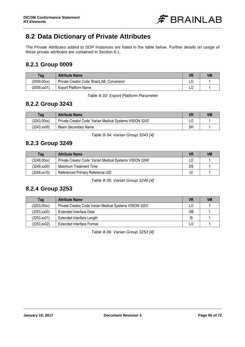
DICOM Conformance Statement RT Elements
January 19, 2017 Document Revision 3 Page 65 of 72
8.2 Data Dictionary of Private Attributes
The Private Attributes added to SOP Instances are listed in the table below. Further details on usage of these private attributes are contained in Section 8.1.
8.2.1 Group 0009
Tag Attribute Name VR VM
(0009,00xx) Private Creator Code 'BrainLAB_Conversion' LO 1
(0009,xx01) Export Platform Name LO 1
Table 8-33: Export Platform Parameter
8.2.2 Group 3243
Tag Attribute Name VR VM
(3243,00xx) Private Creator Code ‘Varian Medical Systems VISION 3243’ LO 1
(3243,xx09) Beam Secondary Name SH 1
Table 8-34: Varian Group 3243 [4]
8.2.3 Group 3249
Tag Attribute Name VR VM
(3249,00xx) Private Creator Code ‘Varian Medical Systems VISION 3249’ LO 1
(3249,xx00) Maximum Treatment Time DS 1
(3249,xx10) Referenced Primary Reference UID UI 1
Table 8-35: Varian Group 3249 [4]
8.2.4 Group 3253
Tag Attribute Name VR VM
(3253,00xx) Private Creator Code Varian Medical Systems VISION 3253’ LO 1
(3253,xx00) Extended Interface Data OB 1
(3253,xx01) Extended Interface Length IS 1
(3253,xx02) Extended Interface Format LO 1
Table 8-36: Varian Group 3253 [4]
DICOM Conformance Statement
RT Elements
Page 66 of 72 Document Revision 3 January 19, 2017
8.3 Coded Terminology and Templates
See [1].

DICOM Conformance Statement RT Elements
January 19, 2017 Document Revision 3 Page 67 of 72
8.4 Grayscale Image Consistency
Not supported.
DICOM Conformance Statement
RT Elements
Page 68 of 72 Document Revision 3 January 19, 2017
8.5 Standard Extended/Specialized/Private SOP Classes
None
DICOM Conformance Statement RT Elements
January 19, 2017 Document Revision 3 Page 69 of 72
8.6 Private Transfer Syntaxes
None.

DICOM Conformance Statement RT Elements
January 19, 2017 Document Revision 3 Page 71 of 72
9 Indexes
9.1 Index of Tables
Table 1-1: Common Management Applications ........................................................................... 3 Table 1-2: Applications ................................................................................................................ 4 Table 1-3: Performers ................................................................................................................. 4 Table 1-4: Supported network services ....................................................................................... 5 Table 1-5: Supported media profiles ........................................................................................... 6 Table 4-1: Commonly supported Transfer Syntaxes (for association negotiation) ..................... 16 Table 4-2: Superset of supported Storage SOP Classes with Transfer Syntax mapping ........... 18 Table 4-3: Superset of supported Query/Retrieve SOP Classes with Transfer Syntax
mapping ............................................................................................................................. 19 Table 4-4: Commonly proposed Application Context Name ...................................................... 19 Table 4-5: Commonly supported number of associations .......................................................... 19 Table 4-6: Commonly proposed Presentation Contexts - Find Studies, Series and Instances. .. 20 Table 4-7: Patient Root and Study Root Request Identifier for FIND-SCU ................................ 21 Table 4-8: Patient Selection proposed Presentation Contexts – Find Patient ............................ 21 Table 4-9: Multiple Brain Mets SRS Application supported SOP Classes .................................. 23 Table 4-10: Multiple Brain Mets SRS Application proposed Presentation Contexts – Save
Instances ............................................................................................................................ 24 Table 4-11: Multiple Brain Mets SRS Application supported SOP Classes ................................ 25 Table 4-12: Cranial SRS Application proposed Presentation Contexts – Save Instances .......... 26 Table 4-13: Spine SRS Application supported SOP Classes ..................................................... 27 Table 4-14: Spine SRS Application proposed Presentation Contexts – Save Instances ............ 28 Table 4-15: Dose Review Application supported SOP Classes ................................................. 29 Table 4-16: Dose Review Application supported SOP Classes ................................................. 31 Table 4-17: RT QA Application supported SOP Classes ........................................................... 33 Table 4-18: RT QA Application proposed Presentation Contexts – Save Instances .................. 34 Table 4-19: DICOM RT Export Performer supported SOP Classes ........................................... 35 Table 4-20: DICOM RT Export proposed Presentation Contexts – Save Instances ................... 36 Table 5-1: Multiple Brain Mets SRS supported Media Interchange Profiles. .............................. 40 Table 5-2: Patient Selection supported SOP Classes and Transfer Syntaxes ........................... 40 Table 5-3: Brainlab BL-EXPORT Profiles. ................................................................................. 41 Table 5-4: BL-RT-EXPORT SOP Classes and Transfer Syntaxes. ........................................... 42 Table 6-1: Application and performer specific supported character sets .................................... 43 Table 8-1: RT Structure Set Storage IOD .................................................................................. 47 Table 8-2: RT Plan Storage IOD ............................................................................................... 48 Table 8-3: RT Dose Storage IOD .............................................................................................. 48 Table 8-4: Patient Module ......................................................................................................... 49 Table 8-5: General Study Module .............................................................................................. 49 Table 8-6: Patient Study Module ............................................................................................... 50 Table 8-7: General Series Module ............................................................................................. 50 Table 8-8: Frame of Reference Module ..................................................................................... 50 Table 8-9: (Enhanced) General Equipment Module................................................................... 50 Table 8-10: General Image Module ........................................................................................... 51 Table 8-11: Image Pixel Module ................................................................................................ 51 Table 8-12: Image Plane Module .............................................................................................. 51 Table 8-13: Multi-frame Module................................................................................................. 51 Table 8-14: SOP Common Module ........................................................................................... 52
DICOM Conformance Statement
RT Elements
Page 72 of 72 Document Revision 3 January 19, 2017
Table 8-15: Common Instance Reference Module .................................................................... 52 Table 8-16: RT Series Module .................................................................................................. 52 Table 8-17: General Image Module (RT Dose) .......................................................................... 52 Table 8-18: General Image Module ........................................................................................... 52 Table 8-19: Image Pixel Module (RT Dose) .............................................................................. 53 Table 8-20: Structure Set Module .............................................................................................. 54 Table 8-21: ROI Contour Module .............................................................................................. 54 Table 8-22: RT ROI Observations Module ................................................................................ 55 Table 8-23: Approval Module .................................................................................................... 55 Table 8-24: General RT Plan Module ........................................................................................ 56 Table 8-25: RT Prescription Module .......................................................................................... 57 Table 8-26: RT Tolerance Tables Module ................................................................................. 57 Table 8-27: RT Patient Setup Module ....................................................................................... 58 Table 8-28: RT Fraction Scheme Module .................................................................................. 59 Table 8-29: RT Beams Module ................................................................................................. 61 Table 8-30: Varian Extended Interface Module ......................................................................... 61 Table 8-31: RT Dose Module .................................................................................................... 62 Table 8-32: RT DVH Module ..................................................................................................... 62 Table 8-33: Export Platform Parameter ..................................................................................... 65 Table 8-34: Varian Group 3243 [4] ............................................................................................ 65 Table 8-35: Varian Group 3249 [4] ............................................................................................ 65 Table 8-36: Varian Group 3253 [4] ............................................................................................ 65
9.2 Index of Figures
Figure 1-1: Overview of a Brainlab system running applications and performers ......................... 3 Figure 4-1: Patient Selection Application Data Flow Diagram .................................................... 11 Figure 4-2: General Application Data Flow Diagram .................................................................. 11 Figure 4-3: General Performer Data Flow Diagram ................................................................... 12 Figure 4-4: Simplified sequencing of the standard interactive use case. .................................... 14 Figure 4-5: Simplified sequencing of Performer activities. ......................................................... 15 Figure 5-1: The Patient Selection Data Flow Diagram ............................................................... 39