DIAPHRAGM WALL SUPPORTED BY GROUND ANCHORS … · 150 . DIAPHRAGM WALL SUPPORTED BY GROUND ANCHORS...
7
150 DIAPHRAGM WALL SUPPORTED BY GROUND ANCHORS AND INCLINED STRUTS: A CASE STUDY *Adnan Anwar Malik 1 , Gorkem Dora 2 , Ramy Derar 3 and Majid Naeem 3 1 Science & Engineering, Saitama University, Japan; 2,4 Ammico Contracting Company, Qatar; 3 Qatar Industrial Manufacturing Company, Qatar *Corresponding Author, Received: 16 Oct. 2018, Revised: 29 Dec. 2018, Accepted: 13 Jan. 2019 ABSTRACT: Diaphragm wall is one of the options to support deep excavation for the construction of basements in an urban area having constraints of space due to nearby structures. The subsurface conditions and nearby existing structures generally decide whether the diaphragm wall will be cantilever or propped. Here is a case study on a diaphragm wall for Qatar Industrial Manufacturing Company Building that comprises of 4 basements, ground floor, mezzanine, podium, and 38 floors. The planned excavation depth for the four basements was 15.95m. The subsurface ground consisted of made ground/fill material, Caprock, Simsima Limestone, Midra Shale and Rus formation. Plaxis 2D software was used to analyze the diaphragm wall. The analysis results showed that ground anchors were required to limit the deflection of the wall within the allowable deflection. Moreover, due to unavailability of foundation details for neighbor building, the ground anchor option was dropped, and inclined steel struts were considered, only in that section. As the inclined steel struts were supported by pile foundation, therefore lateral load analysis was performed through LPile software. Staad Pro. software was also used to analyze the waler beams. The target points at the top of the diaphragm wall were monitored through Total Station equipment to measure the horizontal deflection of the wall. Keywords: Deep excavation, Diaphragm wall, Ground anchors, Inclined struts, Plaxis 2D 1. INTRODUCTION Any excavation whose depth is more than 6 m is considered as a deep excavation [1, 2]. However, with the advancement in construction technology and the use of computer programming makes it possible to analyze and design the excavation support system for all depths, following the same theories. Therefore, the division of shallow and deep excavation is not meaningful anymore [3]. The selection of excavation support system mainly depends upon the subsurface conditions, excavation depth, adjacent structures, space within the site for machinery, access to the site for the machinery and economics. Diaphragm wall is one of the options if the planned excavation is deep and surrounding by existing structures. It was used first time in the 1950s in Italy, after that it’s use increased throughout the world [3]. Wall displacement is the important criteria for the safety of the support system and surrounding structures. The horizontal movement of the wall up to 2 % of the ultimate depth of excavation is the common range in underground construction [4, 5, 6]. However, this horizontal displacement range is not suitable for the situation where shoring is adjacent to neighbor building/structure. Based on the case histories, Clough and O’Rourke [7] found that the maximum lateral wall movement was approximately 0.2 % of excavation depth. Bose and Som [8] studied the effect of excavation depth on wall-soil deformation by using the finite element method (FEM). The numerical study was conducted to investigate the effect of excavation on ground displacement, and a method was proposed to predict the ground displacement [9]. Zhang, Goh and Xuan [10] presented a semi-empirical model for estimating the maximum wall deflection for braced excavations in clays. Watanabe, Mitsumori, Nishioka and Koda [11] showed the advantage of using nodular diaphragm wall as a vertical shaft against heaving resistance. Case studies on the performance of the diaphragm wall with tie-back anchors and struts were conducted and indicated the advantage of numerical simulation for an efficient design in different part of the world [12-14]. As the subsurface conditions, adjacent structures, foundation details of adjacent structures and excavation depth vary from location to location; therefore, case studies always provide a guide to designers to enhance their designing approach for future works. In this regard, the current paper comprises a case study of deep excavation supported by diaphragm wall in Doha, Qatar. Ground anchors and inclined struts were used to restrict the horizontal movement of the diaphragm wall. The available information of the adjacent building foundation details governs the preference for the selection of ground anchors and inclined struts at the diaphragm wall. The various components of the diaphragm wall were analyzed using advanced computing software such as Plaxis 2D, Staad Pro., and LPile. Survey target points were used to monitor the horizontal movement of the diaphragm wall. International Journal of GEOMATE, May 2019, Vol.16, Issue 57, pp.150 - 156 Geotec., Const. Mat. & Env., DOI: https://doi.org/10.21660/2019.57.8170 ISSN: 2186-2982 (Print), 2186-2990 (Online), Japan
Transcript of DIAPHRAGM WALL SUPPORTED BY GROUND ANCHORS … · 150 . DIAPHRAGM WALL SUPPORTED BY GROUND ANCHORS...
150
DIAPHRAGM WALL SUPPORTED BY GROUND ANCHORS AND INCLINED STRUTS: A CASE STUDY
*Adnan Anwar Malik1, Gorkem Dora2, Ramy Derar3 and Majid Naeem3
1Science & Engineering, Saitama University, Japan; 2,4 Ammico Contracting Company, Qatar; 3Qatar Industrial Manufacturing Company, Qatar
*Corresponding Author, Received: 16 Oct. 2018, Revised: 29 Dec. 2018, Accepted: 13 Jan. 2019
ABSTRACT: Diaphragm wall is one of the options to support deep excavation for the construction of basements in an urban area having constraints of space due to nearby structures. The subsurface conditions and nearby existing structures generally decide whether the diaphragm wall will be cantilever or propped. Here is a case study on a diaphragm wall for Qatar Industrial Manufacturing Company Building that comprises of 4 basements, ground floor, mezzanine, podium, and 38 floors. The planned excavation depth for the four basements was 15.95m. The subsurface ground consisted of made ground/fill material, Caprock, Simsima Limestone, Midra Shale and Rus formation. Plaxis 2D software was used to analyze the diaphragm wall. The analysis results showed that ground anchors were required to limit the deflection of the wall within the allowable deflection. Moreover, due to unavailability of foundation details for neighbor building, the ground anchor option was dropped, and inclined steel struts were considered, only in that section. As the inclined steel struts were supported by pile foundation, therefore lateral load analysis was performed through LPile software. Staad Pro. software was also used to analyze the waler beams. The target points at the top of the diaphragm wall were monitored through Total Station equipment to measure the horizontal deflection of the wall. Keywords: Deep excavation, Diaphragm wall, Ground anchors, Inclined struts, Plaxis 2D
1. INTRODUCTION
Any excavation whose depth is more than 6 m is considered as a deep excavation [1, 2]. However, with the advancement in construction technology and the use of computer programming makes it possible to analyze and design the excavation support system for all depths, following the same theories. Therefore, the division of shallow and deep excavation is not meaningful anymore [3]. The selection of excavation support system mainly depends upon the subsurface conditions, excavation depth, adjacent structures, space within the site for machinery, access to the site for the machinery and economics. Diaphragm wall is one of the options if the planned excavation is deep and surrounding by existing structures. It was used first time in the 1950s in Italy, after that it’s use increased throughout the world [3].
Wall displacement is the important criteria for the safety of the support system and surrounding structures. The horizontal movement of the wall up to 2 % of the ultimate depth of excavation is the common range in underground construction [4, 5, 6]. However, this horizontal displacement range is not suitable for the situation where shoring is adjacent to neighbor building/structure. Based on the case histories, Clough and O’Rourke [7] found that the maximum lateral wall movement was approximately 0.2 % of excavation depth. Bose and Som [8] studied the effect of excavation depth on wall-soil deformation by using the finite element method (FEM). The numerical study was conducted to
investigate the effect of excavation on ground displacement, and a method was proposed to predict the ground displacement [9]. Zhang, Goh and Xuan [10] presented a semi-empirical model for estimating the maximum wall deflection for braced excavations in clays. Watanabe, Mitsumori, Nishioka and Koda [11] showed the advantage of using nodular diaphragm wall as a vertical shaft against heaving resistance. Case studies on the performance of the diaphragm wall with tie-back anchors and struts were conducted and indicated the advantage of numerical simulation for an efficient design in different part of the world [12-14].
As the subsurface conditions, adjacent structures, foundation details of adjacent structures and excavation depth vary from location to location; therefore, case studies always provide a guide to designers to enhance their designing approach for future works. In this regard, the current paper comprises a case study of deep excavation supported by diaphragm wall in Doha, Qatar. Ground anchors and inclined struts were used to restrict the horizontal movement of the diaphragm wall. The available information of the adjacent building foundation details governs the preference for the selection of ground anchors and inclined struts at the diaphragm wall. The various components of the diaphragm wall were analyzed using advanced computing software such as Plaxis 2D, Staad Pro., and LPile. Survey target points were used to monitor the horizontal movement of the diaphragm wall.
International Journal of GEOMATE, May 2019, Vol.16, Issue 57, pp.150 - 156 Geotec., Const. Mat. & Env., DOI: https://doi.org/10.21660/2019.57.8170 ISSN: 2186-2982 (Print), 2186-2990 (Online), Japan
International Journal of GEOMATE, May 2019, Vol.16, Issue 57, pp.150 - 156
151
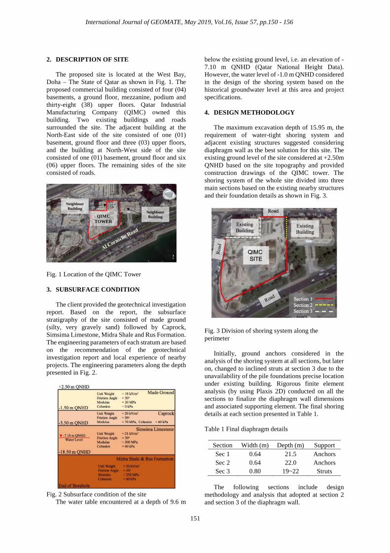
2. DESCRIPTION OF SITE
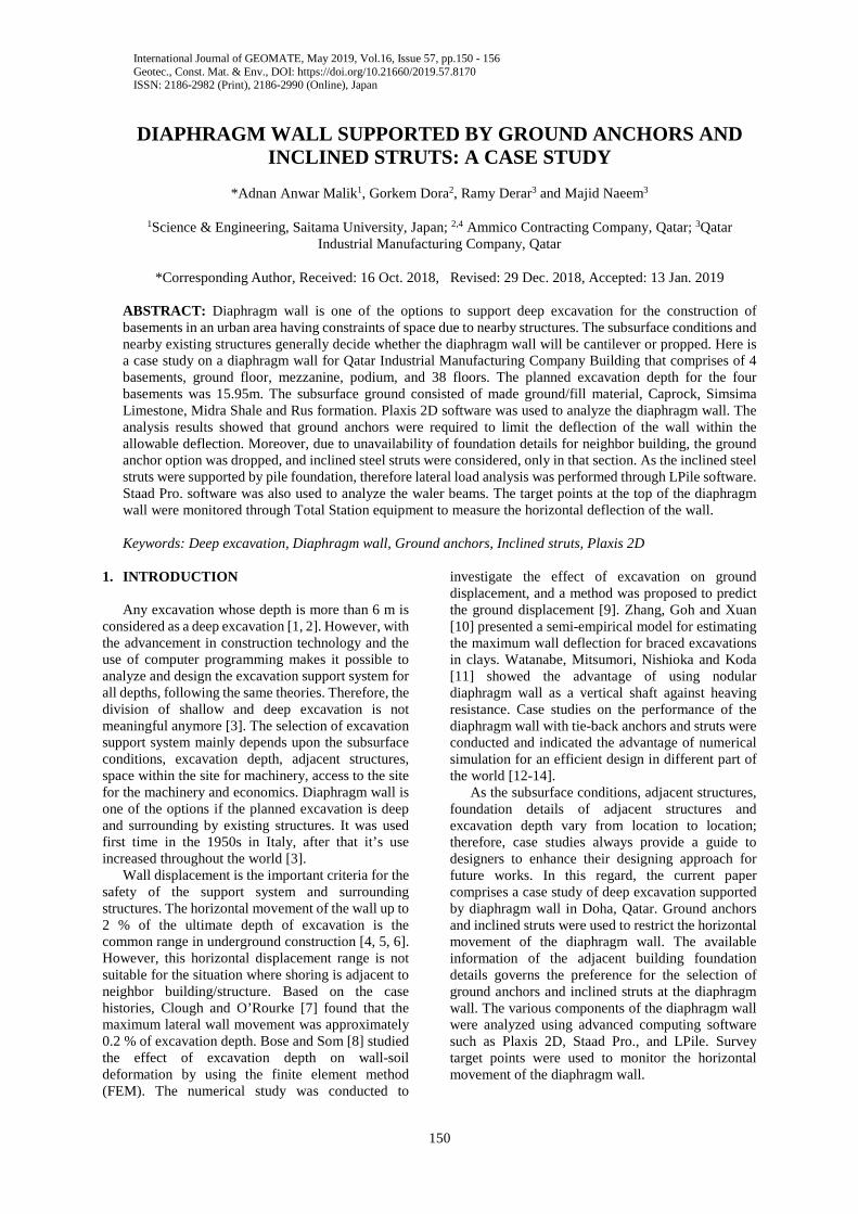
The proposed site is located at the West Bay, Doha – The State of Qatar as shown in Fig. 1. The proposed commercial building consisted of four (04) basements, a ground floor, mezzanine, podium and thirty-eight (38) upper floors. Qatar Industrial Manufacturing Company (QIMC) owned this building. Two existing buildings and roads surrounded the site. The adjacent building at the North-East side of the site consisted of one (01) basement, ground floor and three (03) upper floors, and the building at North-West side of the site consisted of one (01) basement, ground floor and six (06) upper floors. The remaining sides of the site consisted of roads.
Fig. 1 Location of the QIMC Tower 3. SUBSURFACE CONDITION
The client provided the geotechnical investigation
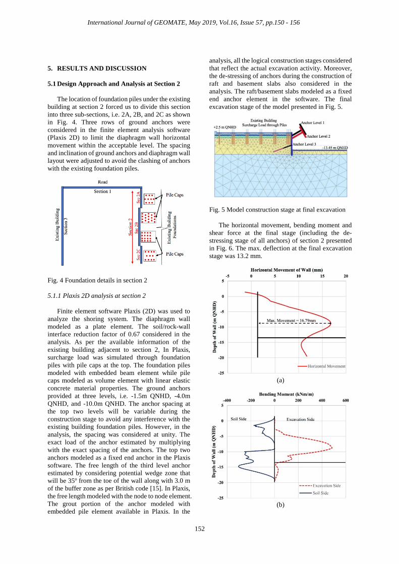
report. Based on the report, the subsurface stratigraphy of the site consisted of made ground (silty, very gravely sand) followed by Caprock, Simsima Limestone, Midra Shale and Rus Formation. The engineering parameters of each stratum are based on the recommendation of the geotechnical investigation report and local experience of nearby projects. The engineering parameters along the depth presented in Fig. 2.
Fig. 2 Subsurface condition of the site
The water table encountered at a depth of 9.6 m
below the existing ground level, i.e. an elevation of -7.10 m QNHD (Qatar National Height Data). However, the water level of -1.0 m QNHD considered in the design of the shoring system based on the historical groundwater level at this area and project specifications. 4. DESIGN METHODOLOGY
The maximum excavation depth of 15.95 m, the requirement of water-tight shoring system and adjacent existing structures suggested considering diaphragm wall as the best solution for this site. The existing ground level of the site considered at +2.50m QNHD based on the site topography and provided construction drawings of the QIMC tower. The shoring system of the whole site divided into three main sections based on the existing nearby structures and their foundation details as shown in Fig. 3.
Fig. 3 Division of shoring system along the perimeter
Initially, ground anchors considered in the analysis of the shoring system at all sections, but later on, changed to inclined struts at section 3 due to the unavailability of the pile foundations precise location under existing building. Rigorous finite element analysis (by using Plaxis 2D) conducted on all the sections to finalize the diaphragm wall dimensions and associated supporting element. The final shoring details at each section presented in Table 1. Table 1 Final diaphragm details
Section Width (m) Depth (m) Support Sec 1 0.64 21.5 Anchors Sec 2 0.64 22.0 Anchors Sec 3 0.80 19~22 Struts
The following sections include design
methodology and analysis that adopted at section 2 and section 3 of the diaphragm wall.
QIMC TOWER
Neighbour Building
Neighbour Building
International Journal of GEOMATE, May 2019, Vol.16, Issue 57, pp.150 - 156
152
5. RESULTS AND DISCUSSION
5.1 Design Approach and Analysis at Section 2
The location of foundation piles under the existing building at section 2 forced us to divide this section into three sub-sections, i.e. 2A, 2B, and 2C as shown in Fig. 4. Three rows of ground anchors were considered in the finite element analysis software (Plaxis 2D) to limit the diaphragm wall horizontal movement within the acceptable level. The spacing and inclination of ground anchors and diaphragm wall layout were adjusted to avoid the clashing of anchors with the existing foundation piles.
Fig. 4 Foundation details in section 2 5.1.1 Plaxis 2D analysis at section 2
Finite element software Plaxis (2D) was used to analyze the shoring system. The diaphragm wall modeled as a plate element. The soil/rock-wall interface reduction factor of 0.67 considered in the analysis. As per the available information of the existing building adjacent to section 2, In Plaxis, surcharge load was simulated through foundation piles with pile caps at the top. The foundation piles modeled with embedded beam element while pile caps modeled as volume element with linear elastic concrete material properties. The ground anchors provided at three levels, i.e. -1.5m QNHD, -4.0m QNHD, and -10.0m QNHD. The anchor spacing at the top two levels will be variable during the construction stage to avoid any interference with the existing building foundation piles. However, in the analysis, the spacing was considered at unity. The exact load of the anchor estimated by multiplying with the exact spacing of the anchors. The top two anchors modeled as a fixed end anchor in the Plaxis software. The free length of the third level anchor estimated by considering potential wedge zone that will be 35o from the toe of the wall along with 3.0 m of the buffer zone as per British code [15]. In Plaxis, the free length modeled with the node to node element. The grout portion of the anchor modeled with embedded pile element available in Plaxis. In the
analysis, all the logical construction stages considered that reflect the actual excavation activity. Moreover, the de-stressing of anchors during the construction of raft and basement slabs also considered in the analysis. The raft/basement slabs modeled as a fixed end anchor element in the software. The final excavation stage of the model presented in Fig. 5.
Fig. 5 Model construction stage at final excavation
The horizontal movement, bending moment and shear force at the final stage (including the de-stressing stage of all anchors) of section 2 presented in Fig. 6. The max. deflection at the final excavation stage was 13.2 mm.
(a)
(b)
International Journal of GEOMATE, May 2019, Vol.16, Issue 57, pp.150 - 156
153
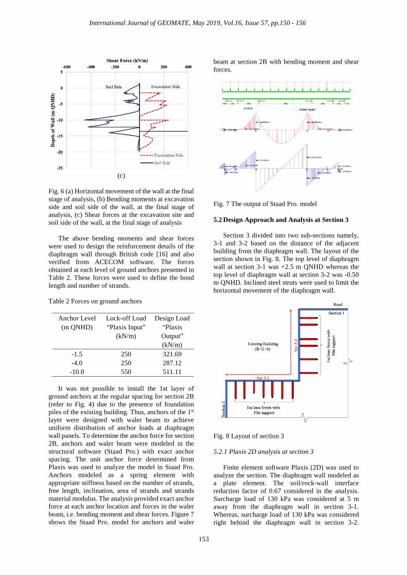
(c)
Fig. 6 (a) Horizontal movement of the wall at the final stage of analysis, (b) Bending moments at excavation side and soil side of the wall, at the final stage of analysis, (c) Shear forces at the excavation site and soil side of the wall, at the final stage of analysis
The above bending moments and shear forces were used to design the reinforcement details of the diaphragm wall through British code [16] and also verified from ACECOM software. The forces obtained at each level of ground anchors presented in Table 2. These forces were used to define the bond length and number of strands.
Table 2 Forces on ground anchors
Anchor Level (m QNHD)
Lock-off Load “Plaxis Input”
(kN/m)
Design Load “Plaxis Output” (kN/m)
-1.5 250 321.69 -4.0 250 287.12
-10.0 550 511.11
It was not possible to install the 1st layer of ground anchors at the regular spacing for section 2B (refer to Fig. 4) due to the presence of foundation piles of the existing building. Thus, anchors of the 1st layer were designed with waler beam to achieve uniform distribution of anchor loads at diaphragm wall panels. To determine the anchor force for section 2B, anchors and waler beam were modeled in the structural software (Staad Pro.) with exact anchor spacing. The unit anchor force determined from Plaxis was used to analyze the model in Staad Pro. Anchors modeled as a spring element with appropriate stiffness based on the number of strands, free length, inclination, area of strands and strands material modulus. The analysis provided exact anchor force at each anchor location and forces in the waler beam, i.e. bending moment and shear forces. Figure 7 shows the Staad Pro. model for anchors and waler
beam at section 2B with bending moment and shear forces.
Fig. 7 The output of Staad Pro. model 5.2 Design Approach and Analysis at Section 3
Section 3 divided into two sub-sections namely, 3-1 and 3-2 based on the distance of the adjacent building from the diaphragm wall. The layout of the section shown in Fig. 8. The top level of diaphragm wall at section 3-1 was +2.5 m QNHD whereas the top level of diaphragm wall at section 3-2 was -0.50 m QNHD. Inclined steel struts were used to limit the horizontal movement of the diaphragm wall.
Fig. 8 Layout of section 3 5.2.1 Plaxis 2D analysis at section 3
Finite element software Plaxis (2D) was used to analyze the section. The diaphragm wall modeled as a plate element. The soil/rock-wall interface reduction factor of 0.67 considered in the analysis. Surcharge load of 130 kPa was considered at 5 m away from the diaphragm wall in section 3-1. Whereas, surcharge load of 130 kPa was considered right behind the diaphragm wall in section 3-2.
International Journal of GEOMATE, May 2019, Vol.16, Issue 57, pp.150 - 156
154
Inclined strut was modeled as a fixed-end anchor and installed at a level of -4.0 m QNHD. The inclination of the strut was 45 degrees. The spacing between the struts was 7.5 m. In the analysis, all the logical construction stages were considered that reflect the actual excavation activity. Moreover, the removal of struts during the construction of raft and basement slabs also considered in the analysis. The raft/basement slabs modeled as a fixed end anchor element in the software. The final excavation stage of the model at section 3-1 presented in Fig. 9.
Fig. 9 Model construction stage at final excavation
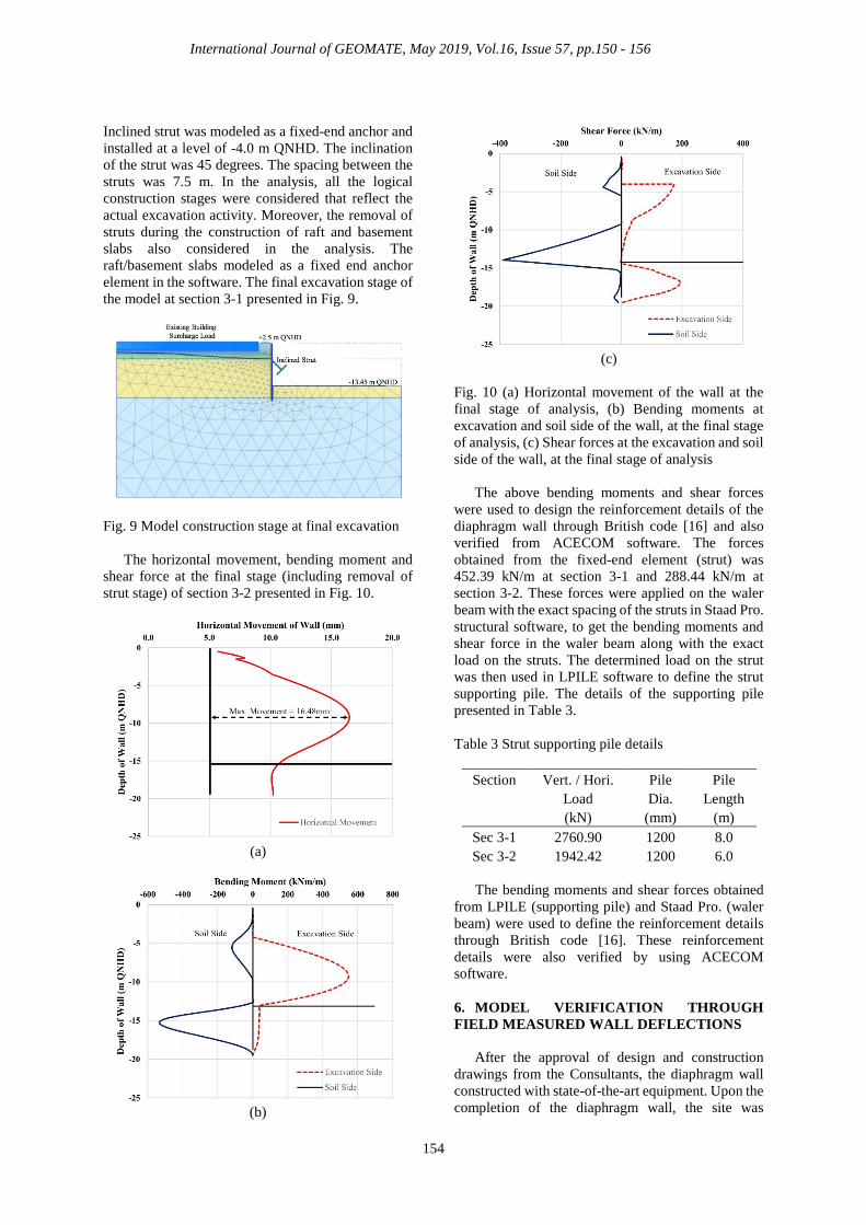
The horizontal movement, bending moment and shear force at the final stage (including removal of strut stage) of section 3-2 presented in Fig. 10.
(a)
(b)
(c)
Fig. 10 (a) Horizontal movement of the wall at the final stage of analysis, (b) Bending moments at excavation and soil side of the wall, at the final stage of analysis, (c) Shear forces at the excavation and soil side of the wall, at the final stage of analysis
The above bending moments and shear forces were used to design the reinforcement details of the diaphragm wall through British code [16] and also verified from ACECOM software. The forces obtained from the fixed-end element (strut) was 452.39 kN/m at section 3-1 and 288.44 kN/m at section 3-2. These forces were applied on the waler beam with the exact spacing of the struts in Staad Pro. structural software, to get the bending moments and shear force in the waler beam along with the exact load on the struts. The determined load on the strut was then used in LPILE software to define the strut supporting pile. The details of the supporting pile presented in Table 3. Table 3 Strut supporting pile details
Section Vert. / Hori. Load (kN)
Pile Dia.
(mm)
Pile Length
(m) Sec 3-1 2760.90 1200 8.0 Sec 3-2 1942.42 1200 6.0
The bending moments and shear forces obtained
from LPILE (supporting pile) and Staad Pro. (waler beam) were used to define the reinforcement details through British code [16]. These reinforcement details were also verified by using ACECOM software. 6. MODEL VERIFICATION THROUGH FIELD MEASURED WALL DEFLECTIONS
After the approval of design and construction drawings from the Consultants, the diaphragm wall constructed with state-of-the-art equipment. Upon the completion of the diaphragm wall, the site was
International Journal of GEOMATE, May 2019, Vol.16, Issue 57, pp.150 - 156
155
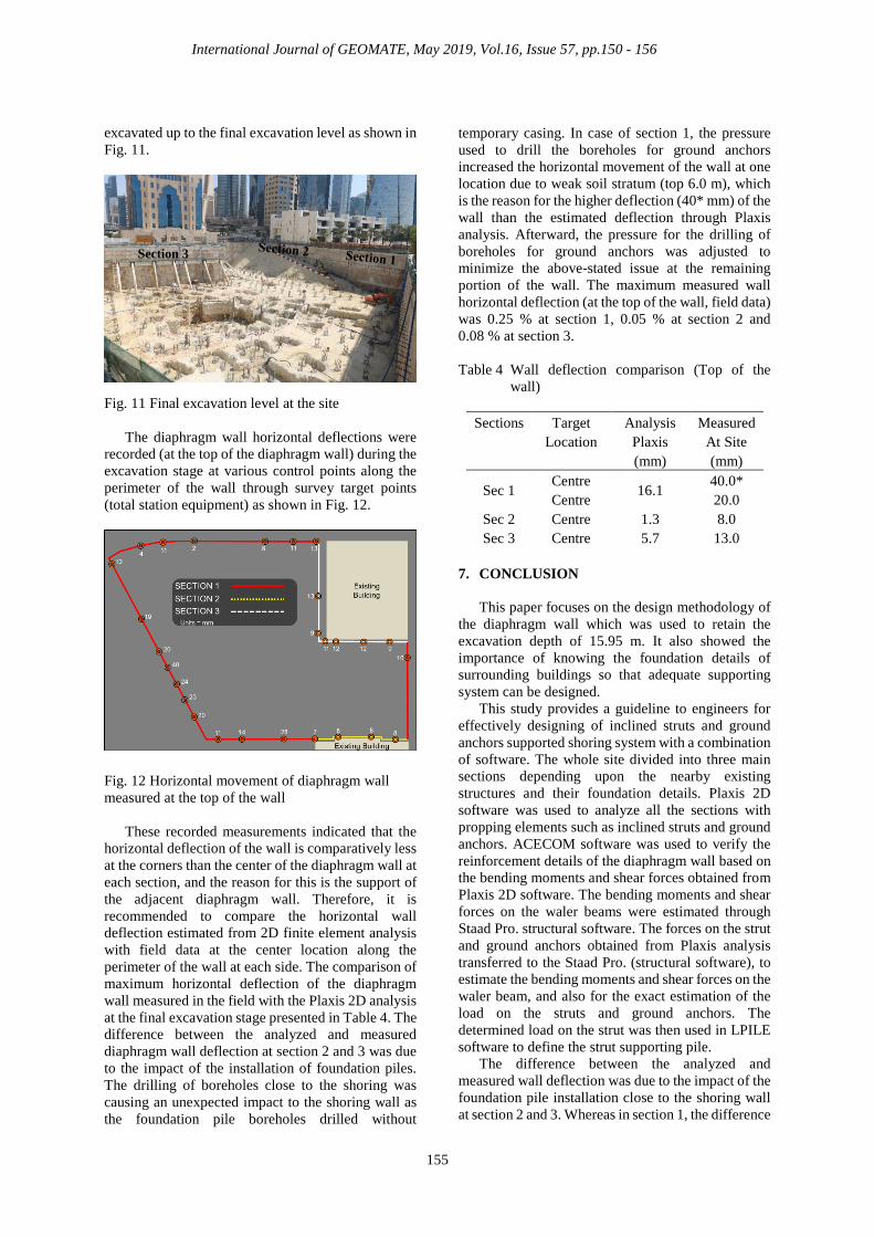
excavated up to the final excavation level as shown in Fig. 11.
Fig. 11 Final excavation level at the site
The diaphragm wall horizontal deflections were recorded (at the top of the diaphragm wall) during the excavation stage at various control points along the perimeter of the wall through survey target points (total station equipment) as shown in Fig. 12.
Fig. 12 Horizontal movement of diaphragm wall measured at the top of the wall
These recorded measurements indicated that the horizontal deflection of the wall is comparatively less at the corners than the center of the diaphragm wall at each section, and the reason for this is the support of the adjacent diaphragm wall. Therefore, it is recommended to compare the horizontal wall deflection estimated from 2D finite element analysis with field data at the center location along the perimeter of the wall at each side. The comparison of maximum horizontal deflection of the diaphragm wall measured in the field with the Plaxis 2D analysis at the final excavation stage presented in Table 4. The difference between the analyzed and measured diaphragm wall deflection at section 2 and 3 was due to the impact of the installation of foundation piles. The drilling of boreholes close to the shoring was causing an unexpected impact to the shoring wall as the foundation pile boreholes drilled without
temporary casing. In case of section 1, the pressure used to drill the boreholes for ground anchors increased the horizontal movement of the wall at one location due to weak soil stratum (top 6.0 m), which is the reason for the higher deflection (40* mm) of the wall than the estimated deflection through Plaxis analysis. Afterward, the pressure for the drilling of boreholes for ground anchors was adjusted to minimize the above-stated issue at the remaining portion of the wall. The maximum measured wall horizontal deflection (at the top of the wall, field data) was 0.25 % at section 1, 0.05 % at section 2 and 0.08 % at section 3.
Table 4 Wall deflection comparison (Top of the
wall)
Sections Target Location
Analysis Plaxis (mm)
Measured At Site (mm)
Sec 1 Centre 16.1 40.0* Centre 20.0
Sec 2 Centre 1.3 8.0 Sec 3 Centre 5.7 13.0
7. CONCLUSION
This paper focuses on the design methodology of the diaphragm wall which was used to retain the excavation depth of 15.95 m. It also showed the importance of knowing the foundation details of surrounding buildings so that adequate supporting system can be designed.
This study provides a guideline to engineers for effectively designing of inclined struts and ground anchors supported shoring system with a combination of software. The whole site divided into three main sections depending upon the nearby existing structures and their foundation details. Plaxis 2D software was used to analyze all the sections with propping elements such as inclined struts and ground anchors. ACECOM software was used to verify the reinforcement details of the diaphragm wall based on the bending moments and shear forces obtained from Plaxis 2D software. The bending moments and shear forces on the waler beams were estimated through Staad Pro. structural software. The forces on the strut and ground anchors obtained from Plaxis analysis transferred to the Staad Pro. (structural software), to estimate the bending moments and shear forces on the waler beam, and also for the exact estimation of the load on the struts and ground anchors. The determined load on the strut was then used in LPILE software to define the strut supporting pile.
The difference between the analyzed and measured wall deflection was due to the impact of the foundation pile installation close to the shoring wall at section 2 and 3. Whereas in section 1, the difference
Section 3

International Journal of GEOMATE, May 2019, Vol.16, Issue 57, pp.150 - 156
156
was due to the impact of the drilling of boreholes for ground anchors. This impact was reduced by adjusting the drilling pressure with respect to surrounding ground conditions.
The maximum measured wall horizontal deflection (at the top of the wall, field data) was 0.25 % at section 1, 0.05 % at section 2 and 0.08 % at section 3.
8. REFERENCES [1] Terzaghi A., and Peck R.B., Soil Mechanics in
Engineering Practice, John Wiley & Sons, New York, 1967.
[2] Peck R.B., Hanson, W.E., and Thornburn, T.H., Foundation Engineering, John Wiley & Sons, New York, 1977.
[3] Ou C.Y., Deep Excavation: Theory and Practice, Taylor and Francis, London, 2006.
[4] Moormann C., Analysis of wall and ground movements due to deep excavations in soft soil based on a new worldwide database. Soils and Foundations, Vol. 44, Issue 1, 2004, pp. 87-98.
[5] Long M., Database for retaining wall and ground movements due to deep excavations. Journal of Geotechnical and Geoenvironmental Engineering, Vol. 127, Issue 3, 2001, pp. 203-224.
[6] Ou C.Y., Hsieh P.G., and Chiou D.C., Characteristics of ground surface settlement during excavation. Canadian Geotechnical Journal, Vol. 30, Issue 5, 1993, pp. 758-767.
[7] Clough G.W., and O’Rourke T.D., Construction induced movements of in situ walls. Proceeding of ASCE Conference on Des. And Perf. of Earth Retaining Structure, Geotech. Spec. Publ. No. 25, ASCE, New York, 1990, pp. 439-470.
[8] Bose S.K., and Som N.N., Parametric study of braced cut by finite element method. Computer Geotechnics, Vol. 22, Issue 2, 1998, pp. 91-107.
[9] Yoo C., and Lee D., Deep excavation-induced ground surface movement characteristics – a numerical investigation. Computer and Geotechnics, Vol. 35, Issue 2, 2008, pp. 231-252.
[10] Zhang W., Goh A.T.C., and Xuan F., A simple prediction model for wall deflection caused by braced excavation in clays. Computer Geotechnics, Vol. 63, 2015, pp. 67-72/
[11] Watanabe K., Mitsumori A., Nishioka H., and Koda M., Evaluation of Heaving Resistance for Deep Shaft using Nodular Diaphragm Wall. International Journal of GEOMATE, Vol. 14, Issue 46, 2018, pp. 40-45.
[12] Nisha J.J., and Muttharam M., Deep excavation supported by diaphragm wall: A case study. Indian Geotechnical Journal, Vol. 47, Issue 3, 2017, pp. 373-383.
[13] Teparaksa W., Deep Excavation in Soft Bangkok Clay Closed to Palaces. International Journal of GEOMATE, Vol. 12, Issue 33, 2017, pp. 85-90.
[14] Teparaksa W., and Teparaksa J., Displacement of Diaphragm Wall for Very Deep Basement Excavation in Soft Bangkok Clay. International Journal of GEOMATE, Vol. 14, Issue 46, 2018, pp. 57-62.
[15] BS 8081, British standard code of practice for ground anchorage. 1989.
[16] BS 8110, Structural use of concrete. Code of practice for design and construction. 1997.
Copyright © Int. J. of GEOMATE. All rights reserved, including the making of copies unless permission is obtained from the copyright proprietors.