
Diaphragm and Shear Wall Design - woodworks.org 1 Diaphragm 2 Diaphragm 2 Boundary (typical) Chord...
173
By: R. Terry Malone, PE, SE Senior Technical Director Architectural & Engineering Solutions [email protected] 928-775-9119 Diaphragm and Shear Wall Design Avalon Bay Communities Photo credit: Arden Photography 120 Union, San Diego, CA Togawa Smith Martin Copyright McGraw-Hill, ICC Portions Based On:
-
Upload
truongdang -
Category
Documents
-
view
228 -
download
1
Transcript of Diaphragm and Shear Wall Design - woodworks.org 1 Diaphragm 2 Diaphragm 2 Boundary (typical) Chord...

By: R. Terry Malone, PE, SESenior Technical DirectorArchitectural & Engineering [email protected]
Diaphragm and Shear Wall Design
Avalon Bay CommunitiesPhoto credit: Arden Photography
120 Union, San Diego, CATogawa Smith Martin
Copyright McGraw-Hill, ICC
Portions Based On:
Course Description
Intended for structural engineers who would like a deeper understanding of advanced shear wall and diaphragm principles, this presentation will provide an in-depth look at wood-frame shear wall and diaphragm designs commonly used for non-residential and multi-family low-rise and mid-rise buildings, including those with rectangular, offset and open-front plans. Topics will include:
• Basic information and method of analysis
• Diaphragms with horizontal offsets
• Diaphragms with large openings
• Shear wall types and anchorage
• SDPWS and ASCE 7 shear wall code requirements
• Offset shear walls and code requirements

Presentation Assumptions
Assumptions:
• Loads to diaphragms and shear walls• Strength level or allowable stress design• Wind or seismic forces.
• The loads are already factored for the appropriate load combinations.
Code and Standards:
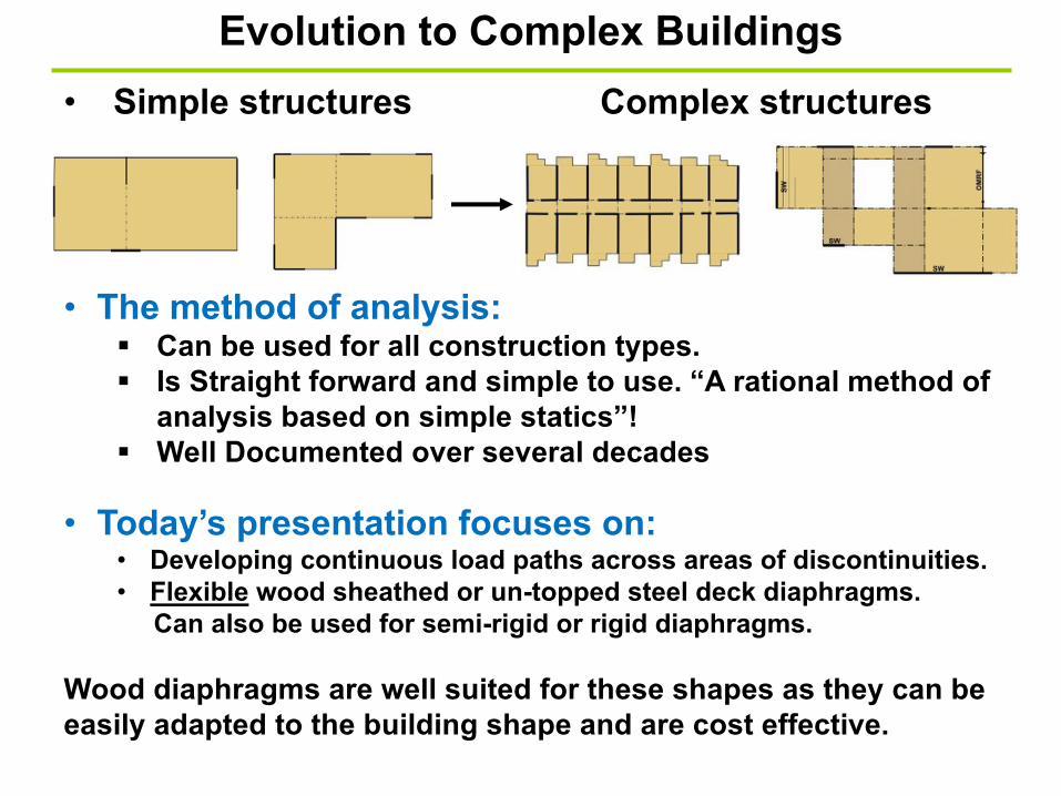
Evolution to Complex Buildings
• Simple structures Complex structures
• The method of analysis:§ Can be used for all construction types.
§ Is Straight forward and simple to use. “A rational method of
analysis based on simple statics”!
§ Well Documented over several decades
• Today’s presentation focuses on:• Developing continuous load paths across areas of discontinuities.
• Flexible wood sheathed or un-topped steel deck diaphragms.
Can also be used for semi-rigid or rigid diaphragms.
Wood diaphragms are well suited for these shapes as they can be
easily adapted to the building shape and are cost effective.

Dis
cont
inuo
us c
hord
sTr
ansv
erse
Cant.
Mid-rise Multi-family
SWSWSWSW
SWSWSWSWSW
SW
Lds. Discontinuous strutsLongitudinal
Lds.
No exteriorShear walls
Flexible, semi-rigid, or rigid???

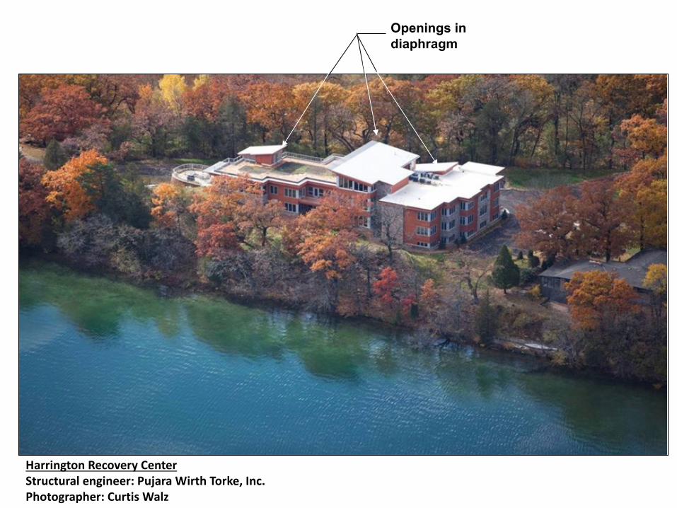
Harrington Recovery CenterStructural engineer: Pujara Wirth Torke, Inc.Photographer: Curtis Walz
Offsets in the diaphragm and walls
Vertically offset Diaphragms?
Openings in diaphragm

• Boundary Elements • Complete Load Paths• Method of Analysis
Basic Information
SW
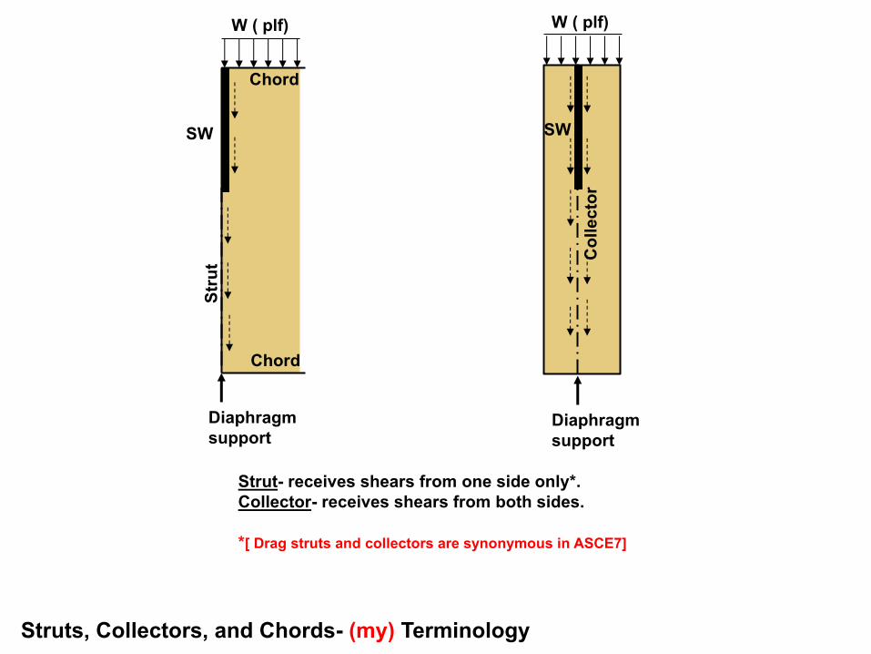
Struts, Collectors, and Chords- (my) Terminology
W ( plf)
Chord
Stru
t
Diaphragm support
Col
lect
or
Strut- receives shears from one side only*. Collector- receives shears from both sides.
*[ Drag struts and collectors are synonymous in ASCE7]
SW
Diaphragm support
Chord
W ( plf)

Diaphragm 1 Diaphragm 2
Diaphragm 2 Boundary (typical)
Chord
Chord
Col
lect
or
Stru
tSt
rut
Chord
Stru
t
Fundamental Principles:A shear wall is a location where diaphragm forces are resisted(supported), and therefore defines a diaphragm boundary location.
Note: Interior shear walls require a full depth collector unless a complete alternate load path is provided
Diaphragm Boundary Elements
SW1
SW2
SW3
Note: All edges of a diaphragm shall be supported by a boundary element. (ASCE 7-10 Section 11.2)
Diaphragm 1 Boundary (typical)
• Diaphragm Boundary Elements:• Chords, drag struts, collectors, Shear walls,
frames• Boundary member locations:
• Diaphragm and shear wall perimeters• Interior openings• Areas of discontinuity• Re-entrant corners.
• Diaphragm and shear wall sheathing shall not be used to act as or splice boundary elements. (SDPWS 4.1.4)
• Collector elements shall be provided that are capable of transferring forces originating in other portions of the structure to the element providing resistance to those forces. (ASCE 7-10 Section 12.10.2)
Required for Seismic and wind
1 2
B
3
C
A
3. Collectors for shear transfer to individual full-height wall segments shall be provided.
SDPWS 4.3.5.1
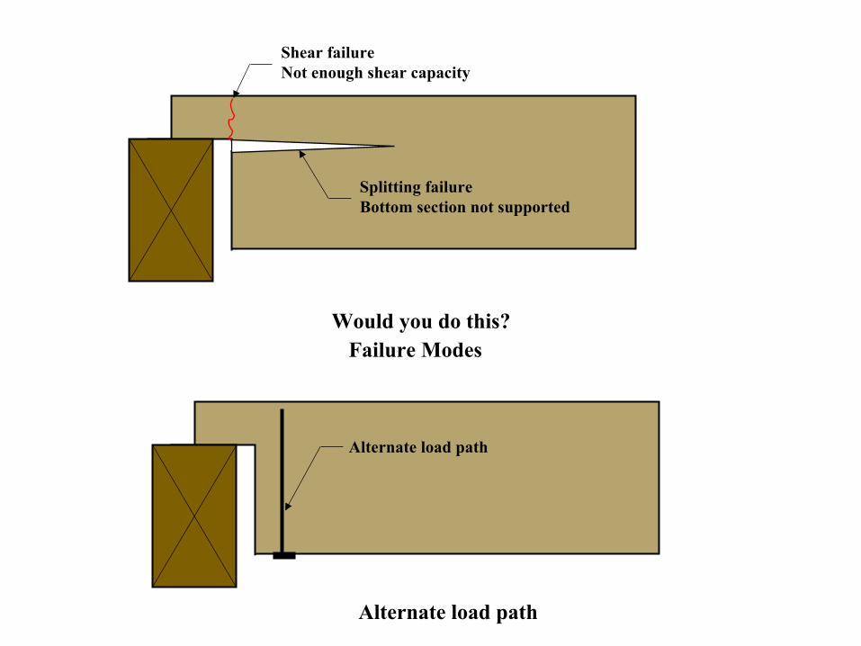
Would you do this?Failure Modes
Shear failureNot enough shear capacity
Splitting failureBottom section not supported
Alternate load path
Alternate load path
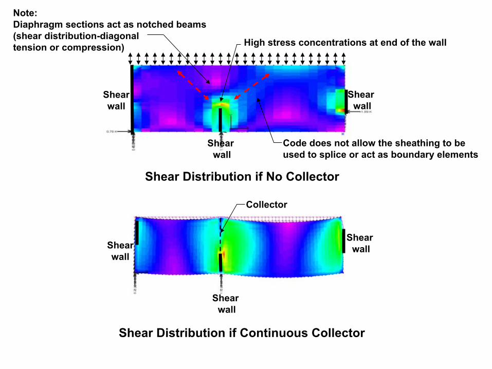
Shear wall
High stress concentrations at end of the wall
Shear Distribution if No Collector
Note:Diaphragm sections act as notched beams(shear distribution-diagonal tension or compression)
Collector
Shear Distribution if Continuous Collector
Code does not allow the sheathing to be used to splice or act as boundary elements
Shear wall
Shear wall
Shear wall
Shear wall
Shear wall
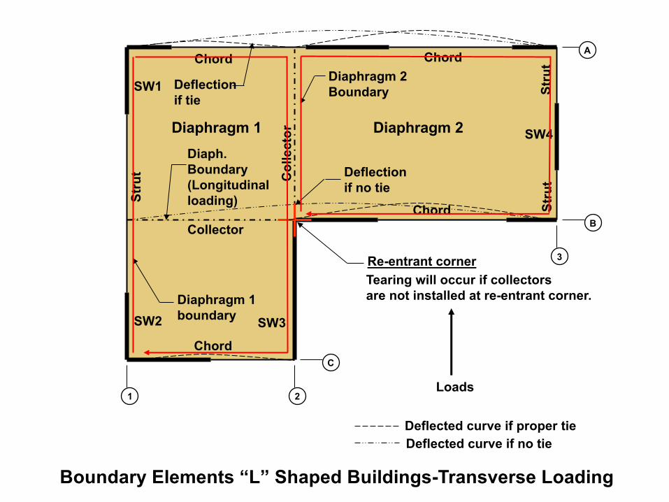
Loads
Col
lect
or
Collector
Diaphragm 1 Diaphragm 2S
trut
Chord Chord
Str
utS
trutDiaphragm 2
Boundary
Diaphragm 1boundary
Re-entrant cornerTearing will occur if collectors are not installed at re-entrant corner.
1 2
A
B
3
C
Deflection if no tie
Deflected curve if proper tieDeflected curve if no tie
SW1
SW2 SW3
SW4
Chord
Chord
Boundary Elements “L” Shaped Buildings-Transverse Loading
Deflection if tie
Diaph.Boundary(Longitudinal loading)
• Boundary Elements • Complete Load Paths• Method of Analysis
Basic Information

Strut/chord
Open
3
4
4
21
F
E
D
C
B
5 8 96 7
Strut/chord
Str
ut (t
yp.)
Strutchord
Strut chord
Strut /chord
Strut/chord
Strut/chord
SW
1
SW2
SW7SW5
SW6
Str
ut
MR
F1
Multiple offsets
Offset struts
Support Support
Col
lect
or
Collector
Collector(typ.)
Collector(typ.)
Collector (typ.)
Col
lect
or (t
yp.)
Analysis: ASCE7-10 Sections:• 1.3.1.3.1-Design shall be based on a rational analysis• 12.10.1-At diaphragm discontinuities such as openings and re-entrantcorners, the design shall assure that the dissipation or transfer of edge (chord) forces combined with other forces in the diaphragm is within shear and tension capacity of the diaphragm.
Complete Load PathsDiscontinuousdiaphragm chords
Offset shear wallsand struts
ASCE7-10 Section 1.4-Complete load paths are required including members and their splice connections
Openingin diaph.
Vertical offset indiaphragm
SW3
10
A
SW4

Strut/chord
Open
3
4
5
21
F
E
D
C
B
6 9 107 8
Strut/chord
Str
ut (t
yp.)
Strutchord
Strut chord
Strut /chord
Strut/chord
Strut/chord
SW
1
SW2
SW7SW5
SW
9
SW6
Str
ut
MR
F1
Support Support
Col
lect
or
Collector
Collector(typ.)
Collector(typ.)
Collector (typ.)
Col
lect
or (t
yp.)
A
Complete Load Paths
SW
8
SW3
Transfer area
Collectors for shear transfer to individual full-height wall segments shall be provided.
SDPWS 4.3.5.1 Where offset walls occur in the wall line, the shear walls on each side of the offset should be considered as separate shear walls and should be tied together by force transfer around the offset (in the plane of the diaphragm).
4
SW4
• Boundary Elements • Complete Load Paths• Method of Analysis
Basic Information
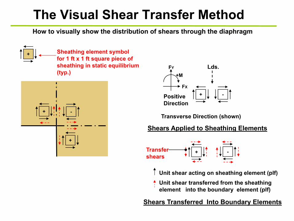
The Visual Shear Transfer MethodHow to visually show the distribution of shears through the diaphragm
+ -
+
Positive Direction
+ -
Transverse Direction (shown)
Lds.
Shears Applied to Sheathing Elements
FY
FX
+M
Sheathing element symbol for 1 ft x 1 ft square piece of sheathing in static equilibrium (typ.)
+
+ -
Shears Transferred Into Boundary Elements
Unit shear transferred from the sheathing element into the boundary element (plf)
Unit shear acting on sheathing element (plf)
Transfer shears
+
-
+-
+ -
-+
Basic Shear DiagramPositive diaph.shear elements
Pos.
Neg.
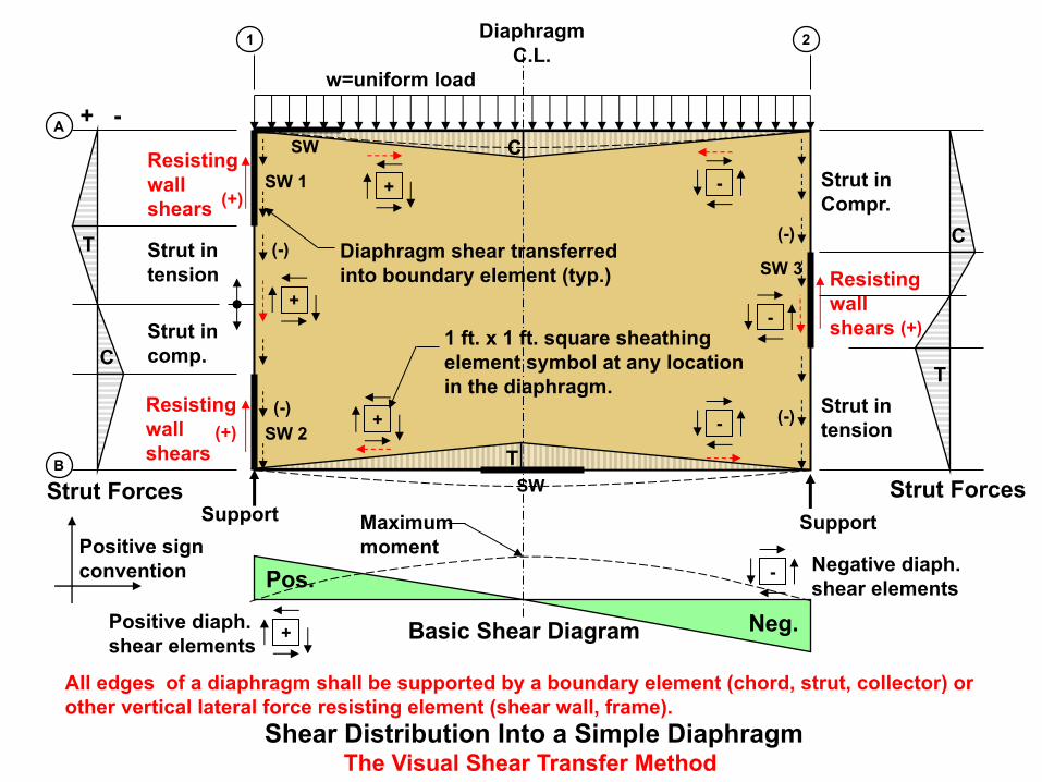
Diaphragm shear transferred into boundary element (typ.)
Strut intension
Resisting wallshears
Resisting wallshears
Resisting wallshears
Strut inCompr.
Strut incomp.
Strut intension
SW 2
SW 1
SW 3
DiaphragmC.L.
Strut Forces Strut ForcesT
C
T
T
C
C
1 2
A
B
Negative diaph.shear elements
(-)
(+)
(+)
(+)
(-)
(-)
(-)
+ -
Positive sign convention
Maximum moment
1 ft. x 1 ft. square sheathingelement symbol at any location in the diaphragm.
Shear Distribution Into a Simple DiaphragmThe Visual Shear Transfer Method
Support Support
SW
SW
All edges of a diaphragm shall be supported by a boundary element (chord, strut, collector) or other vertical lateral force resisting element (shear wall, frame).
w=uniform load
Introduction to Transfer Diaphragmsand Transfer Areas
Col
lect
or
T Collector(strap/blocking or beam/truss)
(support)
(support)
Chord
Chord
TD1
Col
lect
or
T
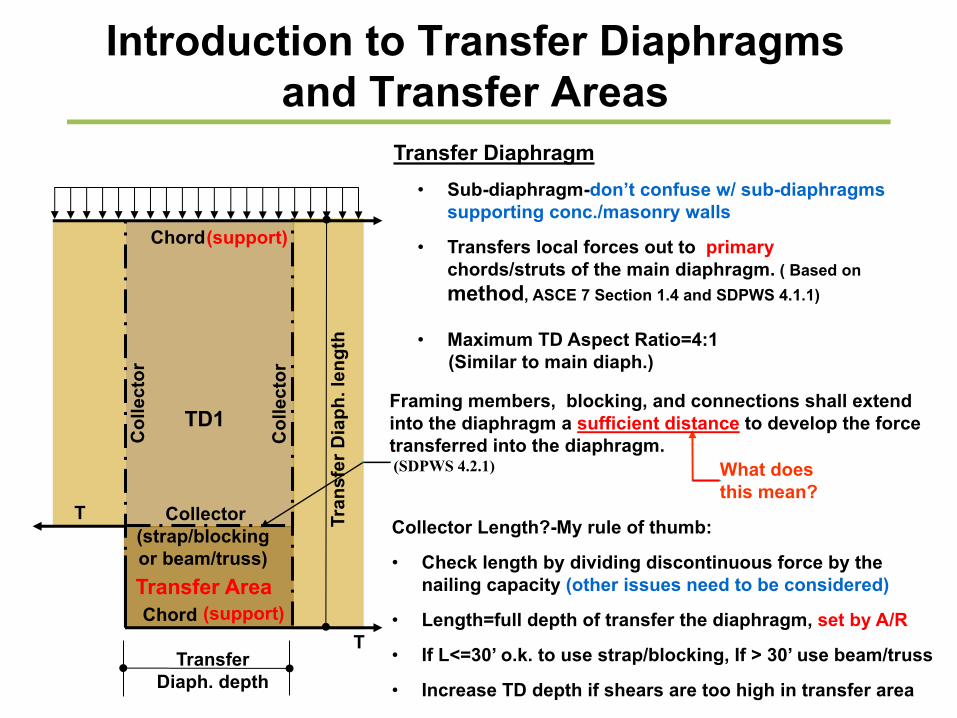
Framing members, blocking, and connections shall extend into the diaphragm a sufficient distance to develop the force transferred into the diaphragm.(SDPWS 4.2.1)
Transfer Diaphragm • Sub-diaphragm-don’t confuse w/ sub-diaphragms
supporting conc./masonry walls
• Transfers local forces out to primary chords/struts of the main diaphragm. ( Based on method, ASCE 7 Section 1.4 and SDPWS 4.1.1)
• Maximum TD Aspect Ratio=4:1 (Similar to main diaph.)
What doesthis mean?
Collector Length?-My rule of thumb:
• Check length by dividing discontinuous force by the nailing capacity (other issues need to be considered)
• Length=full depth of transfer the diaphragm, set by A/R
• If L<=30’ o.k. to use strap/blocking, If > 30’ use beam/truss
• Increase TD depth if shears are too high in transfer area
Transfer Area
Transfer Diaph. depth
Tran
sfer
Dia
ph. l
engt
h
2’
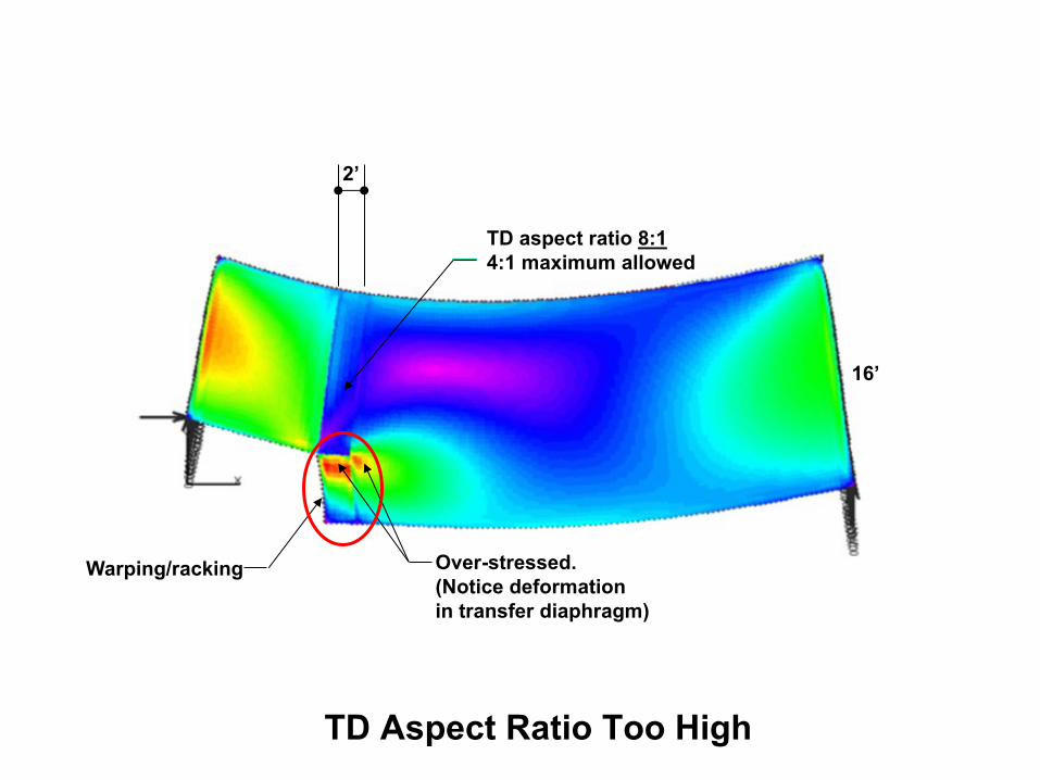
16’
TD aspect ratio 8:14:1 maximum allowed
Over-stressed.(Notice deformationin transfer diaphragm)
TD Aspect Ratio Too High
Warping/racking
SW
SW
Diaph.C.L.
W ( plf)
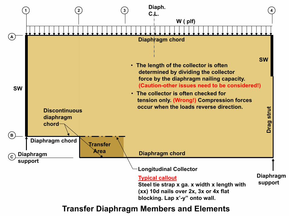
Longitudinal Collector
Diaphragm chord
Discontinuousdiaphragm chord
1 2
A
B
3
CDiaphragm chord
Dra
g st
rut
Diaphragm support
Diaphragmsupport
Transfer Diaphragm Members and Elements
4
Transfer Area
Diaphragm chord
• The length of the collector is oftendetermined by dividing the collector force by the diaphragm nailing capacity.(Caution-other issues need to be considered!)
• The collector is often checked for tension only. (Wrong!) Compression forcesoccur when the loads reverse direction.
Typical calloutSteel tie strap x ga. x width x length with (xx) 10d nails over 2x, 3x or 4x flat blocking. Lap x’-y” onto wall.

2x flat blk’g(tight fit)
Potential gaps
Typical Section
Use Z clip to keep blocking level
Bearing perp. to grain? Alt. 4x blk’g.Tie strap
WSP sht’g.
Joists
Example of Partial Strut/Collector
Collector Compression force distribution
Strut/collector force diagram
Diaphragm unit shear (plf) transfers into blocking
For compression, blocking acts as mini strut/collectorand transfers (accumulates) forces into the next block.
+ ++
No gaps allowed. Diaphragm sheathing is not allowed to transfer strut/collector tension or compression forces.
F4F3F2F1
Cont. tie strap over
F(total)=∑F1+F2+F3+F4
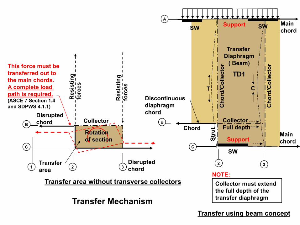
Transfer Mechanism
1 2
B
3
C
T C
Main chord
Main chord
B
C
A
2 3
Disruptedchord
Res
istin
g fo
rces
Transfer area without transverse collectors
Transfer using beam concept
Transfer Diaphragm
( Beam)
Transferarea
Disruptedchord
Support
Support
Collector
Rotationof section
This force must be transferred out to the main chords. A complete load path is required.(ASCE 7 Section 1.4 and SDPWS 4.1.1)
Collector must extend the full depth of the transfer diaphragm
NOTE:
SW
CollectorFull depthChord
Cho
rd/C
olle
ctor
Stru
t
TD1
Cho
rd/C
olle
ctor
SW
Discontinuousdiaphragm chord
SW
Res
istin
g fo
rces
TD1
Support
Support
Discont. Chord / strutF
ab
A
C
B
21Transfer Diaph. depth
Tran
sfer
Dia
ph. l
engt
h
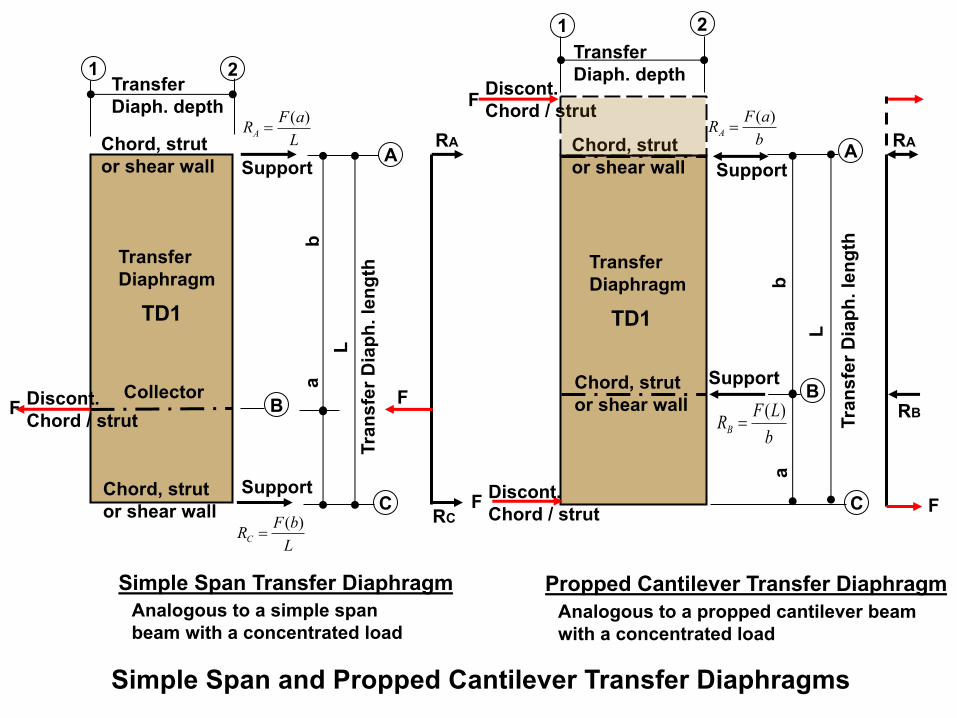
LaFRA)(
=
L
LbFRC)(
=
TransferDiaphragm
Analogous to a simple span beam with a concentrated load
TD1
Support
Support
Discont. Chord / strutF
A
C
B
21Transfer Diaph. depth
Tran
sfer
Dia
ph. l
engt
h
bLFRB)(
=
L
baFRA)(
=
TransferDiaphragm
Analogous to a propped cantilever beam with a concentrated load
Simple Span Transfer Diaphragm
Collector Chord, strutor shear wall
Chord, strut or shear wall
Chord, strut or shear wall
Chord, strut or shear wall
F
F
RB
RA
RC
RA
Propped Cantilever Transfer Diaphragm
ab
Simple Span and Propped Cantilever Transfer Diaphragms
Discont. Chord / strutF
SW
Col
lect
orT T
+
-
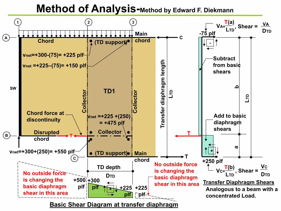
Analogous to a beam with a concentrated Load.
Chord force at discontinuity
Subtract from basic shears
Add to basic diaphragmshears
1
A
B
2
C
Collector
(TD support)
(TD support)
Chord
TD1
Basic Shear Diagram at transfer diaphragm
-75 plf
+250 plf
+300plf +225 +225
plf plf
vnet=+300+(250)= +550 plf
vnet =+225–(75)= +150 plf
3
TD depthTr
ansf
er d
iaph
ragm
leng
th
+
, Shear =VC
DTD DTD
, Shear = VADTD
vnet=+300-(75)= +225 plf
vnet =+225 +(250)= +475 plf
Transfer Diaphragm Shears
ab
VA=
VC=
LTD
T(b)LTD
T(a)LTD
LTD
Method of Analysis-Method by Edward F. Diekmann
+500plf
Main chord
Main chord
Disruptedchord
No outside force is changing the basic diaphragmshear in this area
No outside force is changing the basic diaphragm shear in this area
T
C
Col
lect
or

+ +
+ +
+225 plf +150 plf
+550 plf +475 plf
Resulting net
shear diagram
acting on collector
325 plf 325 plf
Net direction
of shears acting
on collector
Shear Distribution Into The Collector
Direction of shear
transferred into
collector
Collector
• Collector force=area of shear diagram
Shear left=+550-225= +325 plf
2
• Place the net diaphragm shear
on each side of the collector
• Sum shears on collector (based upon
direction of shears transferred onto
collector).
Fcollector=(325+325)(Lcollector)Dir. of force
on collector
B
2 3
Net shears
Note: The net shears
will not always be
equal.
Lcollector
• Place the transfer shears on each side
of the collector
Shear right=+475-150=+325 plf
Collector Force
Diagram

Diaphragms

• Horizontal Offsets• End offsets• Large interior Openings
Diaphragm Design

SW1SW2
Diaph.C.L.
Diaph. chord CollectorC
olle
ctor
Diaph. chord
1 2
A
B
3
C
Col
lect
or
Support
Support
TD1
4
Diaph. chordSupport
Irregularity Requirements for Diaphragms with Horizontal End Offsets-Seismic
Support
A Type 2 Horizontal Irregularity (Re-entrant corner) exists where both projections > 15% of plan dimension in given direction. SDC D-F
• Triggers Section 12.3.3.4• Can also trigger a Type 3 Horizontal Irregularity- abrupt discontinuity or
variation in stiffness in diaphragm SDC D-F
Stru
tStru
tSt
rut
DiscontinuousElements and forces
Varying depth and stiffness

SW1
SW2
Diaph.C.L.
Diaph. chord CollectorC
olle
ctor
Diaph. chord
1 2
A
B
3
C
Col
lect
or
Support
Support
TD1
4
Diaph. chord
Connection design with 25% incr.
Support
Irregularity Requirements for Diaphragms with Horizontal End Offsets-Seismic
Support
ASCE 7-10 Section 12.3.3.4 –A 25% increase is required in diaphragm (inertial) design forces (Fpx) for Type 2 or Type 3 horizontal irregularities located in (SDC D-F) for the following elements:
• Connections of diaphragm to vertical elements and collectors (diaphragm supporting elements-TD)• Collectors and their connections to vertical elements
Design diaphragm connections to SW and struts using 25% increase per ASCE 7-10 Section12.3.3.4. (Grid lines 1 and 4) S
trut
Design transfer diaphragm connections to boundary elements (chords) at Transfer Diaphragm using 25% increase per ASCE 7-10 Section 12.3.3.4. (Grid line C and A)
Str
utS
trut
Design transfer diaphragm connection to collector using 25% increase per ASCE 7-10 Section 12.3.3.4.
Exception: Forces using the seismic load effects including the over-strength factor of Section 12.4.3 need not be increased.
Design collector andconnections to SW using 25% increase per ASCE 7-10 Section 12.3.3.4. (Grid lines 1 and 4)
See 12.10.2 & 12.10.2.1 for collectors
• Diaphragm shears are not required to be increased 25%.

SW 1SW 2
Diaph.C.L.
25’ 20’
15’
w=200 plf
Diaph. chord Collector
Col
lect
or
TD c
hord
s
Diaph. chord
80’
35’50’
Discontinuousdiaphragm chord
1 2
A
B
3
C
Col
lect
or
TD c
hord
s
Support
Support
TD1
+ -
Sign Convention
4
Diaph. chord
F2B
12500 lb
200 plf
25’
F2A
Free body for F2B
1 2
A
B
∑M=035’
M2B ft.-lbF2B=7142.9 lb
Support RL =12500 lb
RR=12500 lb
Example 1-Diaphragm with Horizontal End Offset-Transverse Loading
7500
lb
3500
lb
A/R=2.5:1
Support
Calcs
SW 1
SW 2
Diaph.C.L.
25’ 20’
15’
80’
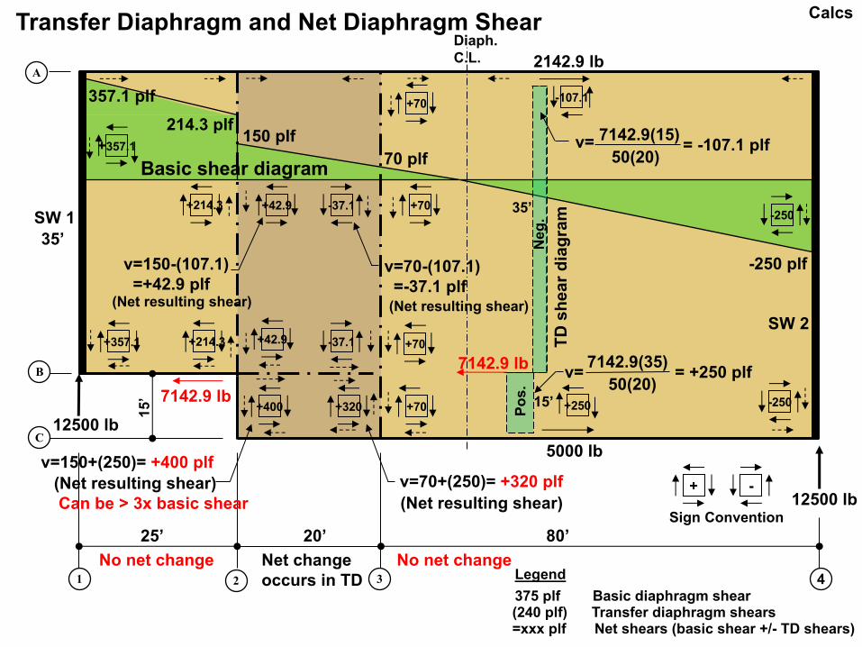
+214.3 +42.9 -37.1
+400 +70
+70
+320
v=150-(107.1)=+42.9 plf
v=70-(107.1)=-37.1 plf
7142.9 lb
v= 50(20)
7142.9(35)= +250 plf
7142.9 lb
2142.9 lb
5000 lb
v= 7142.9(15)
50(20)= -107.1 plf
v=150+(250)= +400 plfv=70+(250)= +320 plf
TD
sh
ea
r d
iag
ram
(Net resulting shear)Can be > 3x basic shear
150 plf 214.3 plf
357.1 plf
70 plf
+250
-107.1
1 2
A
B
3
C
Basic shear diagram
375 plf Basic diaphragm shear
=xxx plf Net shears (basic shear +/- TD shears)(240 plf) Transfer diaphragm shears
No net change Net change occurs in TD
No net changeLegend
35’
+ -
Sign Convention
+357.1 +214.3 +42.9 -37.1 +70
4
-250
+70
+357.1
-250
15’
35’
12500 lb
12500 lb(Net resulting shear)
(Net resulting shear) (Net resulting shear)
Po
s.
Neg
.
-250 plf
Transfer Diaphragm and Net Diaphragm Shear Calcs

SW 1SW 2
Diaph.C.L.
25’ 20’
15’
+42.9 -37.1
+400
F=7142.5 lb
F =7200 lb
F=7200 lb
F=7812.5 lb
C
T
+70
70 plf+320
7142.9 lb
T
7142.9 lb
1 2
A
B
3
C
F=7142.9 lb
+42.9
-37.110.72’
9.27’+230 lb-172.1 lb
Longitudinal Chord Force Diagrams
0 plf
+ -
Sign Convention
+357.1 +214.3 +42.9 -37.1
4
-250
-250
17.5’
+357.1 +214.3
Support
Support
F=7812.5 lb
357.1 plf net
0 plf
Calcs

SW 1SW 2
Diaph.C.L.
25’ 20’
15’
80’
+357.15
+214.3 +42.9 -37.1
+400
+70
+320
F=6000 lb
F=6000 lb(this is not an insignificant force.)
F=3748.5 lb
F=3750 lb
+70
T
Special nailing
(sum of shears to collector or highest boundary nailing-greater of)C
1 2
A
B
3
C
Transverse Collector Force Diagrams
+ -
Sign Convention
+357.15 +214.3 +42.9 -37.1 +70
4
171.4 plf net 107.1 plf net
250 plf net
Calcs

Diaph.C.L.
w1
A B
1
2
3
Deflection of rectangular diaphragm Deflection of
offset diaph.
C
w2Diaphragm Deflection EquationsEquation variables for offset diaphragms• Varying uniform loads • Concentrated loads from discontinuous shear walls• Varying moments of inertia, and sometimes• Different support conditions
ATC7• Modify the bending and shear portion of the
standard rectangular deflection equation to fit the model:
∆"#=%&#'
()*++&#-./
+ 0. 2((#34 +5 6789+
Bending deflection Shear
deflection
Nail slip Adjusted for non-uniform nailing (ATC-7/APA)
Chordslip
NOTE: Multiply deflection x 2.5 for unblocked diaphragmMultiply nail slip by 1.2 if not Structural I plywood
P
Shear Deflection -USDA Research Note FPL-0210• Simplified energy method (Virtual Work).• The integrations of the equations can be reduced to
multiplying the total area of the shear diagramdue to the general loading by the ordinate of the shear diagram due to a dummy load applied at the desired point of shear deflection.
I1 I2
SDPWS combines
Standard deflection equation for simple span, rectangular, rigid supports, fully blocked, uniformly loaded, constant cross section (∆ at C.L.)
6"# = 6: + 6; + 0. 2((<34 +=(67?)
9+
ABCDC
6: = ∫F+ GH
IJ2KL + ∫+
M GH
IJ9KL, OPK
6; =+/
9Q*9∫F+ RS
+T
+
9 KL + ∫+MRSUS = ∫0
# &V
./KL
WXY IZ. 9' − 2APA equation
Cannot use
bb’
L All terms relate to simple span uniformly
loaded

Diaphragm Nailing Callouts
10d
@ 4
/6/1
2 B
1
2 3 Transfer area Boundary (High shear area)
Transfer diaphragm Boundary (Typ.)
Boundary locations
Diaphragm boundary
357.
2 pl
f
320
plf
285
plf
214.
3 pl
f 42
.9 p
lf
37.1
plf
70 p
lf
214.3 plf 357.1 plf
70 plf Basic shear diagram150 plf
10d
@ 6
/6/1
2 B
10d
@ 6
/12
UB
Cas
e I
10d @ 4/6/12 B
10d
@ 6
/12
UB
Cas
e I
10d
@ 6
/12
UB
Cas
e I
Check the shear capacity of the nailing along the collector
Callout all nailing on drawings:• Standard diaphragm nailing• Boundary nailing• Collector nailing
x4x3x1 x2 Special nailing along collectors Sum of shears to collector or highest boundary nailing-greater of
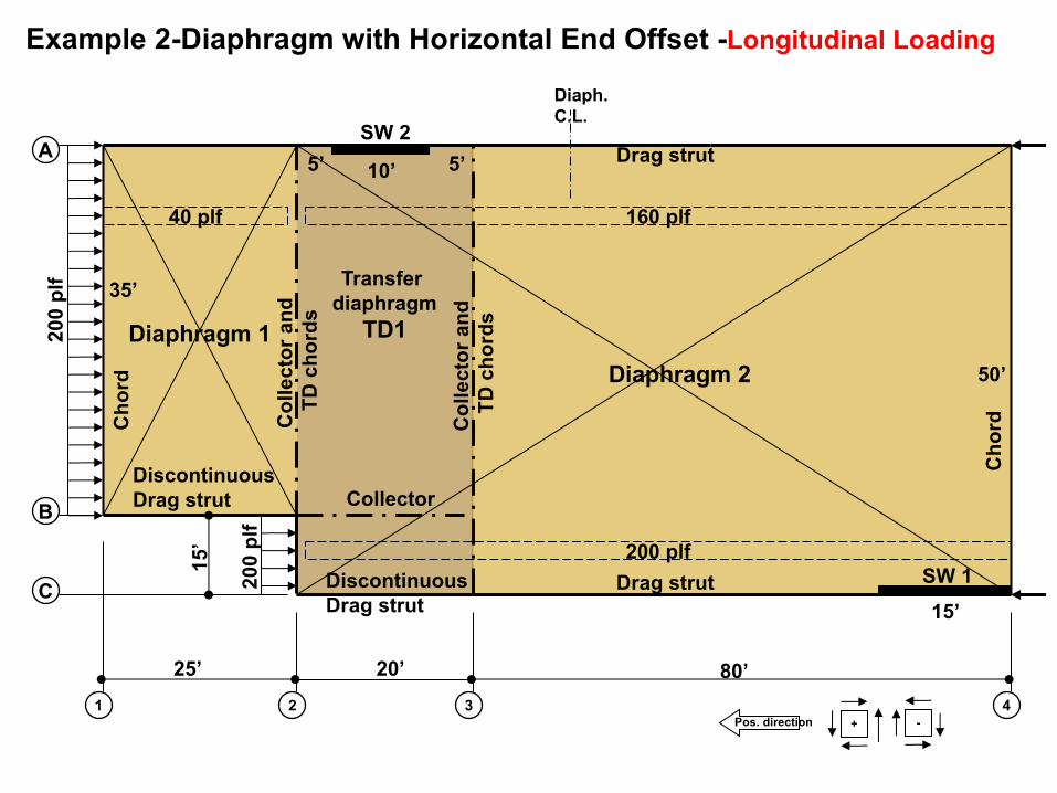
SW 1
Diaph.C.L.
25’ 20’
15’
200
plf
Cho
rd
Collector
Col
lect
or a
nd
TD c
hord
s
80’
Transfer diaphragm
TD1
35’
50’
DiscontinuousDrag strut
1 2
A
B
3
C
4
10’5’
15’
200
plf
Diaphragm 2
Diaphragm 1
SW 2Drag strut
40 plf 160 plf
Cho
rd
5’
+Pos. direction -
200 plfDrag strut
Col
lect
or a
nd
TD c
hord
s
Example 2-Diaphragm with Horizontal End Offset -Longitudinal Loading
DiscontinuousDrag strut

15’
35’
VA SW 2A
B
C
4
SW 1
+Pos. direction -
Dia
ph.
C.L
.
vA
2
BTransfer area
Transfer Diaphragm and Net Diaphragm Shear
(Net shear)
+
-10’
15’
12 3
Vnet=vsw-vdiaph
Neg
.Po
s.
VB
Dia
phra
gm 2
Dia
phra
gm 1
FB
Vnet=vsw-vdiaph
!" = $%&
!" = $%&
vB
vC
(Net shear)
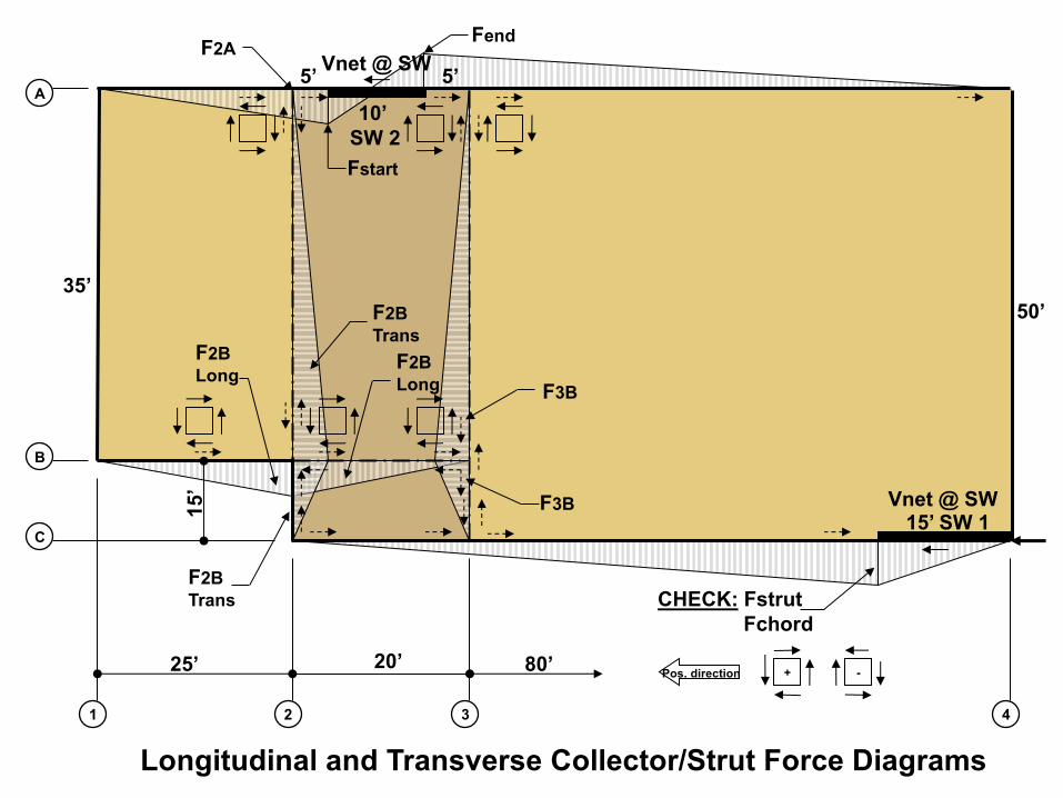
25’ 20’
15’
80’
35’50’
CHECK: FstrutFchord
10’ SW 2
1 2
A
B
3
C
4
15’ SW 1
Vnet @ SW
+Pos. direction -
Longitudinal and Transverse Collector/Strut Force Diagrams
F2A5’ 5’
F3B
F3B
F2BLong
F2BTrans
Fend
Fstart
F2BTrans
F2BLong
Vnet @ SW

Let’s Take a Break

• Horizontal Offsets• End offsets• Large interior Openings
Diaphragm Design

End Openings
w plfDiaph.C.L.
1 2
A
B
3
CD
4 51 2
A
B
3
CD
4
Does not meet A/R
(Envelope)
SW 1
SW 3
SW 2
Basic Shear Diagram
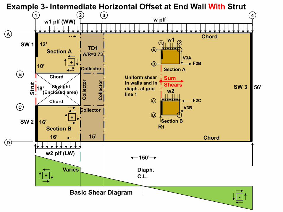
Diaph.C.L.
1 2
A
B
3
C
4
D
TD1A/R=3.73
Skylight(Enclosed area)
w1 plf (WW)
w2 plf (LW)
Varies+
-
Stru
t
w plf
Chord
Chord
Chord
Chord
Collector
Collector
Col
lect
or
Col
lect
or
Section A
Section B
F2CC
D
R1
V3B
Section B
F2B
A
B
1 2
V3A
Section A +
+
w1
w2
Example 3- Intermediate Horizontal Offset at End Wall With Strut
Sum Shears
Uniform shear in walls and in diaph. at grid line 1
10’
12’
18’
16’
16’
15’
56’
150’
SW 1
SW 3
SW 2
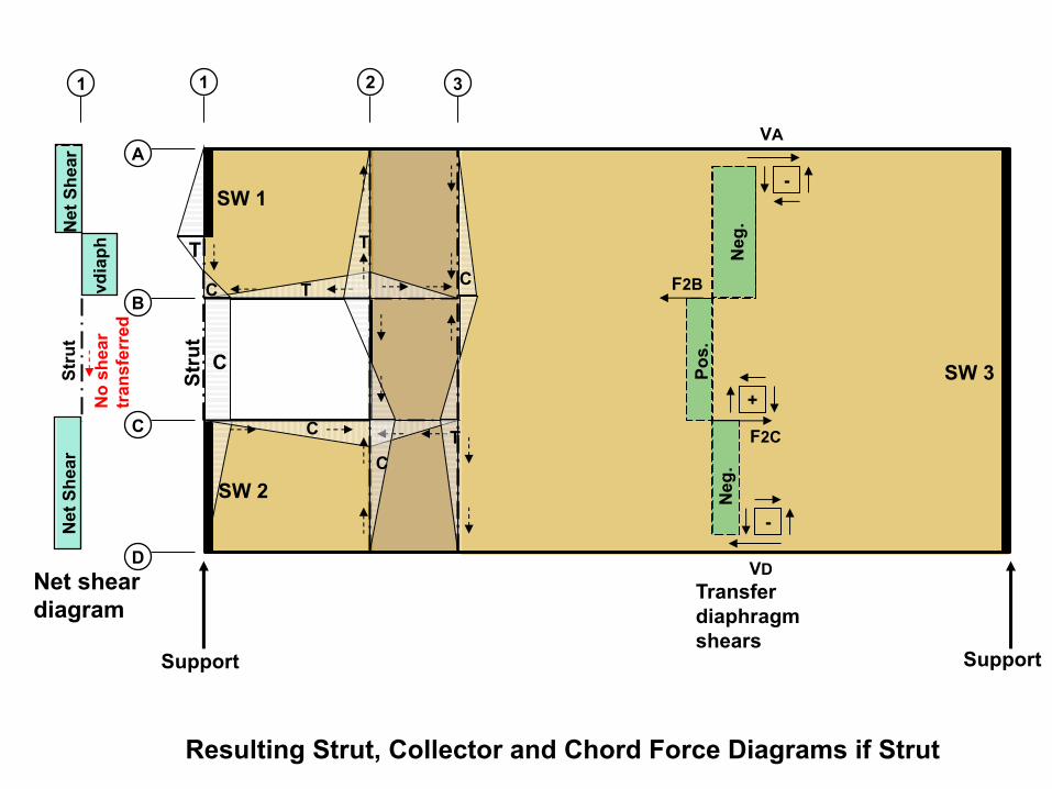
Resulting Strut, Collector and Chord Force Diagrams if Strut
1 2
A
B
3
C
D
Support Support
+
-
-
F2C
F2B
VA
VD
vdia
phN
et S
hear
Stru
t N
et S
hear
Net shear diagram
Stru
t
C
T
C
T
C TC
T
C
No
shea
rtr
ansf
erre
d
Pos.
Neg
. N
eg.
Transfer diaphragm shears
1
SW 1
SW 3
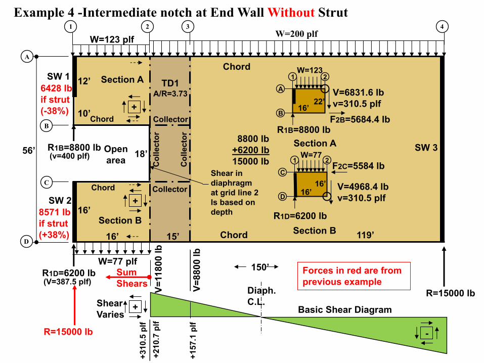
Example 4 -Intermediate notch at End Wall Without Strut
SW 2
Basic Shear Diagram
Diaph.C.L.
1 2
A
B
3
C
4
D
Open area
10’
12’
18’
16’
16’
119’
150’
56’
W=123 plf
W=77 plf
Shear Varies
+210
.7 p
lf
+157
.1 p
lf
15’
+
-
W=200 plf
Chord
Chord
Chord
Chord Collector
Collector
Col
lect
or
Col
lect
or
Section A
Section B
16’
F2C=5584 lb
16’C
D
1 2
R1D=6200 lb
V=4968.4 lbv=310.5 plf
Section B
R1B=8800 lb
16’F2B=5684.4 lb
22’A
B
1 2
V=6831.6 lbv=310.5 plf
Section A
+
+
W=123
W=77
Sum Shears
Shear in diaphragm at grid line 2 Is based on depth
R=15000 lb
R=15000 lb V=11
800
lb
8800 lb+6200 lb15000 lb
6428 lbif strut(-38%)
8571 lbif strut(+38%)
V=88
00 lb
+310
.5 p
lfR1B=8800 lb
R1D=6200 lb(V=387.5 plf)
(v=400 plf)
TD1A/R=3.73
Forces in red are from previous example
SW 1
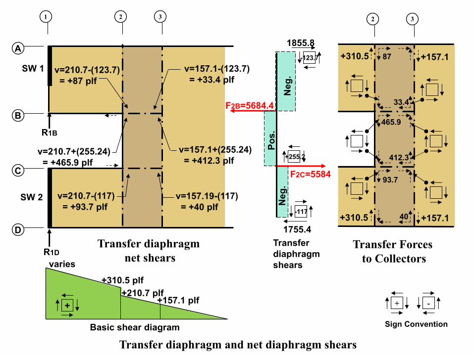
+255.2
-123.7
Neg
. P
os.
-117
Neg
.
SW 2
v=157.1+(255.24)= +412.3 plf
+ -
Sign Convention
Transfer diaphragm and net diaphragm shears
+310.5 plf
varies
+210.7 plf+157.1 plf
v=210.7+(255.24)= +465.9 plf
v=210.7-(117)= +93.7 plf
v=210.7-(123.7)= +87 plf
v=157.1-(123.7)= +33.4 plf
v=157.19-(117)= +40 plf
1 2
A
B
3
C
D
1855.8
1755.4
+
Basic shear diagram
2 3
+157.1
+157.1
+310.5
+310.5
F2C=5584
F2B=5684.4
R1B
R1D
87
33.4
412.3
465.9
40
93.7
Transfer diaphragm shears
Transfer diaphragm net shears
Transfer Forces to Collectors
SW 1
SW 3
SW 2
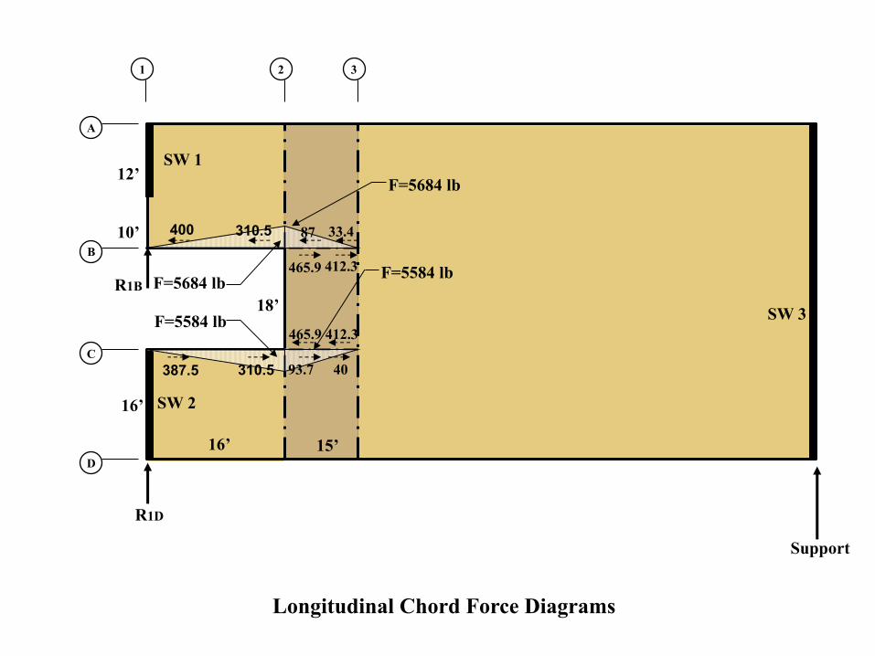
Longitudinal Chord Force Diagrams
F=5584 lb
F=5584 lb
33.4
412.3
465.9 412.3
40
F=5684 lb
F=5684 lb
87
465.9
93.7
1 2
A
B
3
C
D
Support
R1B
R1D
18’
10’
12’
16’
16’
15’
400
310.5387.5
310.5

SW 3
SW 2
Traverse Strut/Collector Force Diagrams
F=3469.2
F=4917
Vsw=6200 lbvsw=387.5 plfvnet=0 plf
-400 p
lf+333.3
3 p
lf
F=4000
F=3469.2
F=2271.4
F=1872.2
F=1872.2 lb
33.4
412.3
93.7
40
87
465.9
93.7
40
465.9
412.3
33.487
1 2
A
B
3
C
D
SW 1
Vsw=8800 lbvsw=733.33 plfvnet=733.3-400=333.33 plf
R1B=8800
R1D=6200 lb
157.1
157.1
310.5387.5
310.5400
157.1
157.1
Net shear diagram

• Horizontal Offsets• End offsets• Large interior Openings
Diaphragm Design

ASCE 7-10 Section 12.3.3.4 (SDC D-F) -Horizontal irregularity Type 3 requires a 25% increase in the diaphragm design forces determined from 12.10.1.1 (Fpx) for the following elements:• Connections of diaphragm to vertical
elements and collectors (diaphragm supporting elements).
• Collectors and their connections to vertical elements.
• Use of over-strength forces is not commonly considered to be triggered for boundary elements at diaphragm openings. However, the 25% increase does apply.
Diaphragms With Large Interior Openings
w plf
Diaph.C.L.
1 2
A
B
3
C
D
4 5
Type 3 Horizontal Irregularity-SDC D-F-Diaphragm Discontinuity Irregularity.Diaphragm discontinuity irregularity exists where there is an abrupt discontinuity or variation in stiffness, including a cut-out or open area greater than 50% gross enclosed diaphragm area, or a change in effective diaphragm stiffness of more than 50% from one story to the next.
Diaphragm shears are not required to be increased 25%.
Exception: Forces using the seismic load effects including the over-strength factor of Section 12.4.3 need not be increased.
collector
collector
collector
collector

Roof pop-up section with opening below.
Common Openings In Diaphragms
Skylight or atrium opening
Clerestory windows
Stairwell access to roof
End opening
Optional strut
Harrington Recovery CenterStructural engineer: Pujara Wirth Torke, Inc.Photographer: Curtis Walz
Openings in diaphragm

Affect of Size and location in Diaphragm
Basic Shear Diagram
Location and Magnitude of Shear
Size of opening
Local shears lower
Local shears higher
StairwellsElevators
IBC 2305.1.1 Openings in shear panels that materially effect their strength shall be fully detailed on the plans and shall have their edges adequately reinforced to transfer all shear stresses.
Most openings of any significant size should be checked.
It is strongly recommended that analysis for a diaphragm with an opening should be carried out except where all four of the following items are satisfied: a. Depth no greater than 15% of diaphragm depth; b. Length no greater than 15% of diaphragm length; c. Distance from diaphragm edge to the nearest
opening edge is a minimum of 3 times the largeropening dimension;
d. The diaphragm portion between opening and diaphragm edge satisfies the maximum aspect ratio requirement. (all sides of the opening)
FPInnovationsDesign example: Designing for openings in wood diaphragm
C.L. opening
I.P.
I.P.
1 2
A
B
3
C
D
54
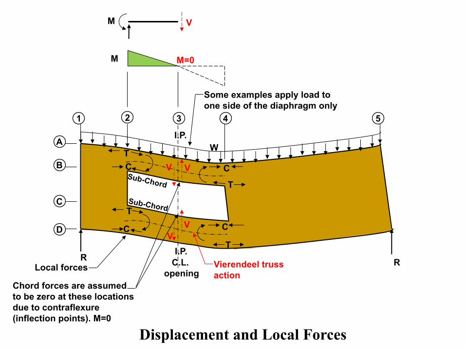
Displacement and Local Forces
Vierendeel trussaction
V
V V
V
T
T
C
C
W
T
T
C
C
Local forces
.
.
R R
Some examples apply load to one side of the diaphragm only
Chord forces are assumedto be zero at these locationsdue to contraflexure (inflection points). M=0
Sub-Chord
Sub-Chord
M
V M
M=0
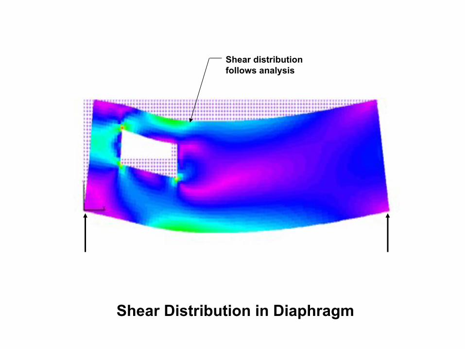
Shear Distribution in Diaphragm
Shear distribution follows analysis

A/R
A/RA/R A/R
A/RA/R
ATC 7, Diekmann, FPInnovationsIf the sections above, below or on each side of the opening does not meet code aspect ratio limits it should be ignored (not stiff enough).
All sections must meet Code required aspect ratios.
TransferDiaphragm
(TD)
TD
Aspect Ratio Issues
Opening
A/RA/ROpening
Easy to visualize if header section is replaced by a wire.
Transfer diaphragms are required if the opening size affects the shear or tension capacity of the diaphragm.
Opening
TD

R
w plf
F2
F2 F3
F4
F4
02 =SM 03 =SM 04 =SM
V4
Diaph.C.L.
TD2 TD1 Opening
F3
1 2
A
B
3
C
D
4
Element III
Element II
Element IV
Element I
Inflection point.
V2V3
V1
Basic shear diagram without openings
F=0
5
V5
Basic Shear Diaphragm With Opening
V4R
V2RV3V1
V5
Opening Analysis-Diekmann method
Typical method of analysis (APA Report 138), ATC-7, and FPInnovations
1. Calculate the chord forces at grid lines 2, 3, and 4 using FBD’s.
2. Determine the basic diaphragm shears without an opening.
3. Determine the diaphragm shears with an opening.
4. Break the sections above and below the opening into elements as shown.
5. Determine the local forces at each corner of each segment by FBD’s.
6. Determine the net resulting shears and forces (+/-) by combing the shears with and without an opening using a table .
Using the visual shear transfer method
1. Determine shear (V4) at grid line 4. 2. Break the sections above and below the
opening into elements as shown.3. Calculate the chord force at grid line 3.4. Starting at grid line 4 and moving to the left,
sum forces at each corner of each segmentto determine the local forces, by FBD’s.
5. Calculate all chord, collector forces, andtransfer diaphragm shears and forcesusing the visual shear transfer method.
V4LV2L
F=0

Example 5-Pop-up Roof Section
W=200 plf
Diaph.C.L.
1 2
A
B
3
C
D
4 6
40’20’
60’
200’
28’
20’
12’
20’
5
W=50 plf
W=123 plfW=200 plf
W=77 plf
W=30 plf
Basic Shear Diaphragm With Opening (plf)
v4R
v2Rv3v1
v5
v4Lv2L
v6
TD1 TD2
A/R TD1=TD2=3.0:1 o.k.
A/R main diaphragm and upper section=3.33:1
Wind Loads (ASD)MainW=200 plf
At openingWw=123 plfLw=77 plf
At pop-up (20 psf)Ww=50 plfLw=30 plf
V=2
720
V=6
720
V=8
320
V=1
3920
V=1
9520
V=2
1120
RR=21280RL=25120
V=2
5120
1600
lb
1600
lb
1 2
A
B
3
C
D
W=123 plfW=200 plf
W=77 plf
W=30 plfTD1
RL=25120
1600
lb
W=50 plf13280
13280
!" = $ 40’20’
8’
Open to below
W=50 plf
W=30 plf
W=80 plf
SW1600 lb
1600 lb
Open tobelow
F3A
F3D
Sub-Chord
Sub-Chord
FPInnovations:Hgt.> 0.15 dDiaph.Width>0.15 Ldiaph.End dist.< 3x widthDetailed analysis required
SW 1
Diaph.C.L.
0 0
0 0
+
+
+
+10104 l
b
7964 l
b
7964 l
b
5824 l
b
5824 l
b2496 l
b
(360.9
plf
)
(284.4
plf
)
(284.4
plf
)
(208 p
lf)
2496 l
b
5956 l
b
5956 l
b
9416 l
b
(784.6
plf
)
(496.3
plf
)
(208 p
lf)
(496.3
plf
)
F2C
F4A
F4C
F4BF2B
F2A
F4DF2D
13280 lb
13280 lb
12810 lb 7076 lb
18204 lb6827 lb
6453 lb 4924 lb
200 plf
1 2
A
B
3
C
D
54
Start here
470 lb 20340 lb
200 plf123 plf123 plf
77 plf 77 plf
28’
12’
20’
20’
20’ 20’
20’
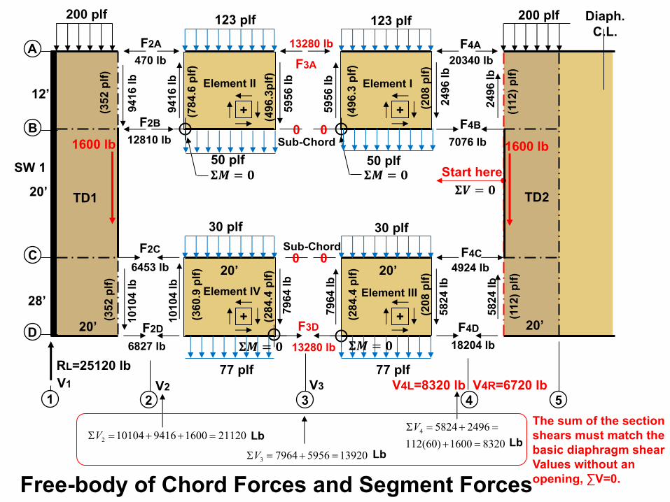
2112016009416101042 =++=SV Lb
13920595679643 =+=SV Lb83201600)60(112
249658244
=+=+=SV
Lb
TD1 TD2
Free-body of Chord Forces and Segment Forces
!" = $ !" = $
!" = $!" = $
The sum of the section shears must match thebasic diaphragm shear Values without an opening, ∑V=0.
Sub-Chord
Sub-Chord
V1 V2 V3 V4L=8320 lb V4R=6720 lb
50 plf50 plf
30 plf30 plf
RL=25120 lb
1600 lb1600 lb9416 l
b10104 l
b
(112)
plf
)(1
12)
plf
)
(352 p
lf)
(352 p
lf)
!% = $
F3A
F3D
Element III
Element II
Element IV
Element I

Net Shears-Left Transfer Diaphragm
20’
+ -
A
B
1
C
D
3
T.D.1
Sign convention
Neg.
Pos.
Neg.
352418.7
Basic Shear Diagram
w
Transfer diaphragm shears
2
6453 lb
879.6 lb
12810 lb
20’
7236.6 lb
418.7-361=+57.7
418.7+278.7=+639.7
418.7-44=+374.7
+374.7
360.
978
4.6
360.
9
-361
+278.7
-44
352-361=-9
-
352+278.7= +630.7
352-44=+308
1600 lb
6453 lb
12810 lb

20’
-+
A
B
4
C
D
TD2
Sign convention
Transfer diaphragm shears
vnet=112-168.2=-56.2 plf
vnet=112+185.7=+297.7 plf
vnet=112-60.55=+51.45plf
5
+45.33+112
Basic Shear Diagram
vnet=45.33-168.2=-122.8 plf
vnet=45.33+185.7=+231.02 plf
vnet=45.33-60.55 =-15.22 plf
45.33
45.33
45.33
w
45.33
45.33
4924 lb
1211 lb
7076 lb
3363 lb
-168.2
+185.7
-60.55
1600 lb
4924 lb
7076 lb
Net Shears-Right Transfer Diaphragm
Neg.
Neg.
Pos.

Collector Force Diagrams-Left Side
-+
A
B
1
C
D
3
TD1
Sign convention
w
2
F=12800 lb F=9524 lb
1600
lb
F=1476 lb
F=6453 lb
57.7
697.3
9
630.7
697.3
347.7
630.7
308
360.9308
784.6
630.7
308
9
630.7
360.9
T
C
T
C
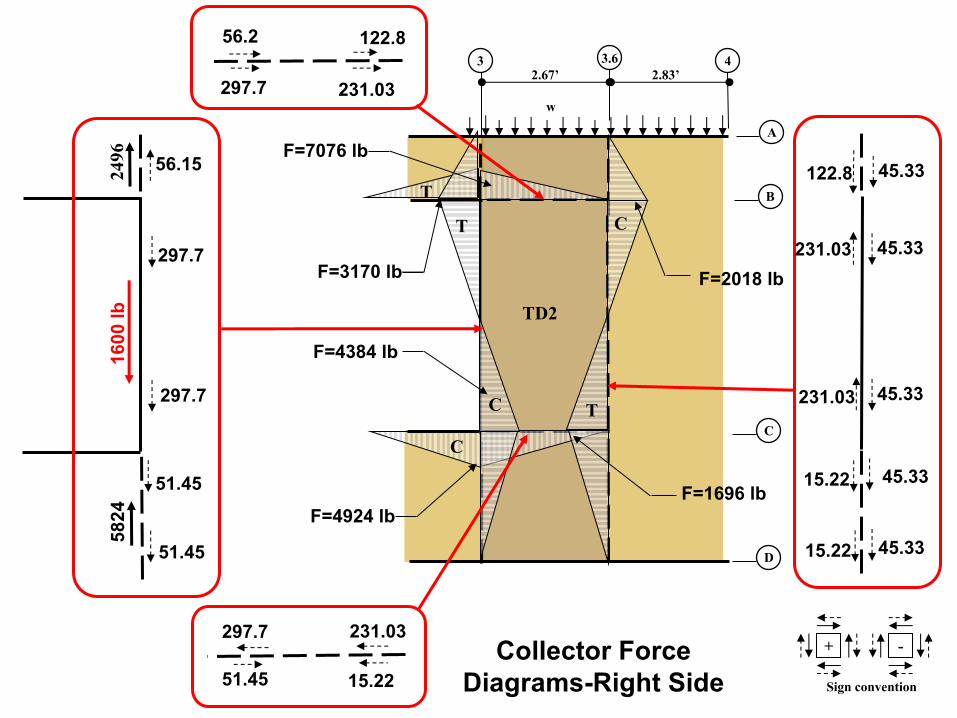
Collector Force Diagrams-Right Side
2.67’
-+
A
B
3
C
D
4
TD2
Sign convention
2.83’
w
3.6
F=3170 lb F=2018 lb
1600
lb
F=1696 lb
F=4384 lb
56.2
297.7
122.8
231.03
297.7
51.45
231.03
15.22
15.22
45.33
231.03
15.22
122.8
231.03
297.7
5824
51.45
56.15
297.7
2496
51.45
F=7076 lb
F=4924 lb
45.33
45.33
45.33
45.33
TC
T C
T
C
A57.67
D20’ 20’40’
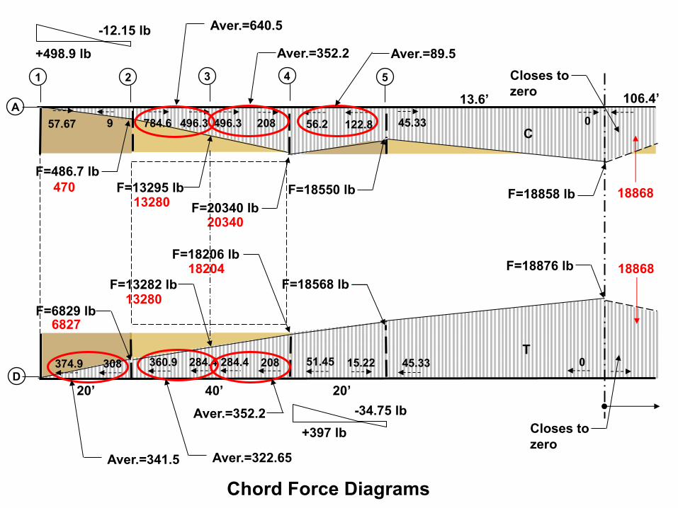
T
Chord Force Diagrams
1 2 3 54
09 784.6 208 56.2 122.8 45.33
51.45 15.22 045.33
496.3 496.3
374.9 308 360.9 208284.4 284.4
C
F=486.7 lbF=13295 lb
F=20340 lbF=18858 lb
F=18876 lb
F=18550 lb
Closes to zero
F=6829 lb
F=18206 lb
Aver.=640.5
Aver.=352.2
F=13282 lb F=18568 lb
+397 lb-34.75 lb
Aver.=322.65
Aver.=352.2
Aver.=89.5
13.6’ 106.4’
+498.9 lb-12.15 lb
18868
2034013280
470
Aver.=341.5
1886818204
13280
6827
Closes to zero

SW 1 SW 2
Final Strut/Chord Force Diagrams
1 2
A
B
3
C
D
54
TD1 TD2
T T
C
C
T
C T
T
C
C

Shear Walls
Shear Wall Design
• Shear Wall Types
• Shear wall Anchorage
• SDPWS Code Requirements
• Complete Load Paths
• ASCE 7 Offset Shear Wall Requirements
• Offset Shear Walls
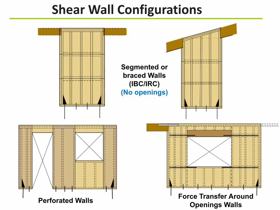
Shear Wall Configurations
Perforated Walls Force Transfer Around Openings Walls
Segmented or braced Walls
(IBC/IRC)(No openings)
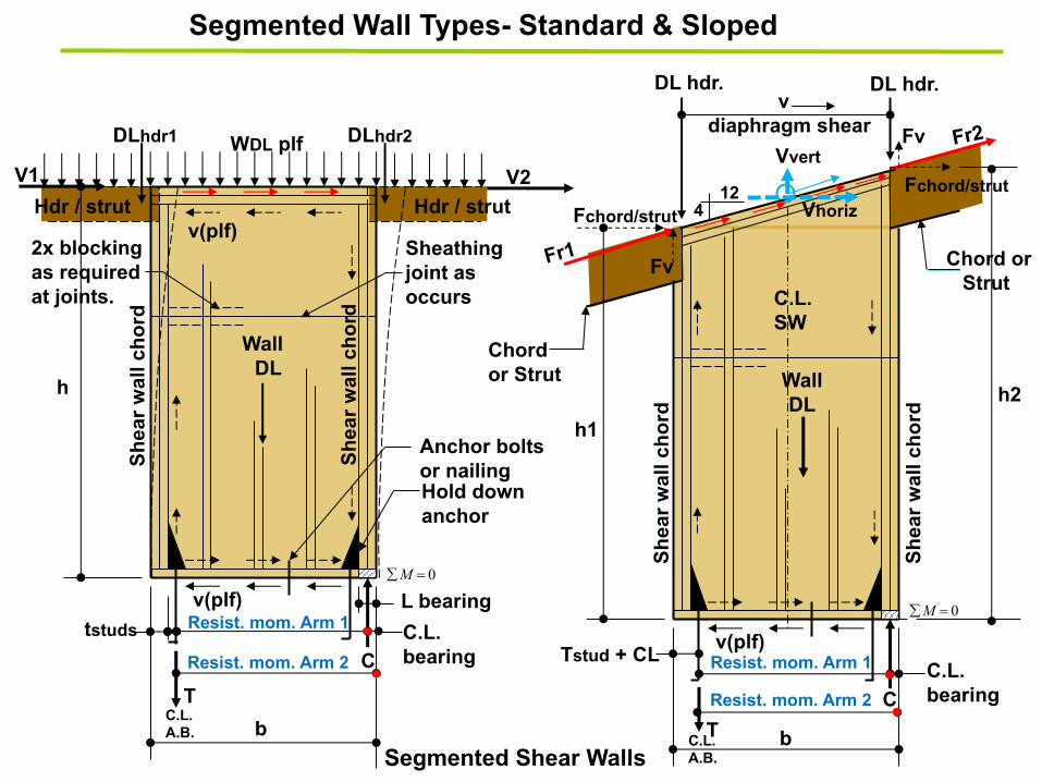
WallDL
V1
v(plf)
Sh
ea
r w
all
ch
ord
Sh
ea
r w
all
ch
ord
h
Resist. mom. Arm 1C.L. bearingC
C.L. A.B.
T
b
Sheathing joint as occurs
2x blockingas requiredat joints.
DLhdr2DLhdr1
Anchor bolts or nailing Hold down anchor
V2
v(plf)
WDL plf
tstuds
Sh
ea
r w
all
ch
ord
Sh
ea
r w
all
ch
ord
h1
Resist. mom. Arm 1
C
C.L. A.B.
T b
Tstud + CLC.L. bearing
Chord orStrut
Chordor Strut
Fr1
Fr2
h2WallDL
DL hdr. DL hdr.
412
C.L.SW
v diaphragm shear
0=åM
Fv
Fchord/strut
Fchord/strut
Fv
Vvert
Vhoriz
Segmented Shear Walls
Segmented Wall Types- Standard & Sloped
L bearing
Hdr / strut Hdr / strut
Resist. mom. Arm 2
Resist. mom. Arm 2
v(plf)
0=åM

Dead Load Distribution
b/2
b
This section Supported by the first floor bearing width
This section in bearing
Preference & Engineering Judgement
Rigid Body
Semi-Rigid Body
Rigid Body
45 60
Short Walls
Long Walls
b/2
b/2

Wood structural panels –
Unblocked
Wood structural panels –
Blocked
Particleboard – Blocked
Diagonal sheathing,
conventional
Gypsum board
Portland Cement Plaster
Structural Fiberboard
Type Maximum height-width ratios
AWC SDPWS Table 4.3.4-Maximum shear wall dimension ratios-Wind and seismic
Footnotes
1. Walls having aspect ratios exceeding 1.5:1 shall be blocked shear walls.
Allowable Aspect Ratios & Adjustment Factors
4.3.4.2
For wood structural panel shear walls with aspect ratios (h/b) greater than 2:1, the nominal shear
capacity shall be multiplied by the Aspect Ratio Factor (WSP) =1.25-0.125h/b.
For structural fiberboard shear walls with aspect ratios (h/b) greater than 1:1, the nominal shear
capacity shall be multiplied by the Aspect Ratio Factor (fiberboard) =1.09-0.09 h/b.
C4.3.4.2
2: 1
3.5:1
2:1
2:1
2:1(1)
2:1 (1)
3.5:1

WallDL
V or F
Shea
r wal
l cho
rd
Shea
r wal
l cho
rd
h
CT b
WDL plf
Segmented Shear Wall Deflection and Stiffness∆"#
Deflection of unblocked segmented shear wall• Use Eq.4.3-1 with v/Cub per 4.3.2.2 and Table 4.3.3.2
• Max. height unblocked=16 feet
v v v
∆$% =' (
)*+,-
./0 +()*+
,233345
+ ,+ ∆5
ATS
Wall stiffness k = 6∆
ATS
CX
∆"#= '(,-./+ +
(,233345
+ ,∆5+
Vertical elongation• Device elongation• Rod elongation
Bending
Apparent shear stiffness• Nail slip• Panel shear deformation
SDPWS 3 term deflection equation
4.3-1
∆"#= '(,-./+ +
(,4(7(
+3. 9:,;<+ ,∆5+
Bending
Shear
Traditional 4 term deflection equation
C4.3.2-1
Nail slip
SDPWS combines
Rod elongation(Wall rotation)
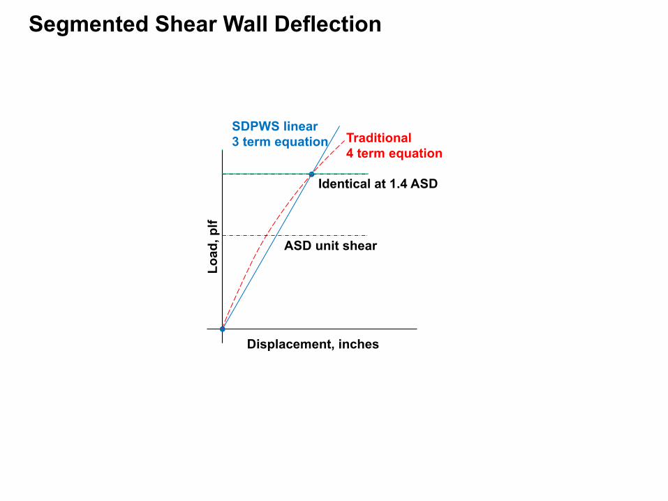
Segmented Shear Wall Deflection
SDPWS linear3 term equation
Identical at 1.4 ASD
ASD unit shear
Traditional4 term equation
Displacement, inches
Load
, plf

Perforated Shear Walls- Empirical Design
Hdr
Hold downs at Ends per section 4.3.6.4.2
Intermediate uplift anchorage is required at each full height panel locations… ”in addition to…” per section 4.3.6.4.2.1.
Collector per SDPWS section 4.3.5.3(Full length of wall)
Top and bottom of wall cannot be Stepped or sloped
Opening
Hdr
Opening
Use other methods
Typical boundary member
All full hgt. sections must meet the aspect ratio requirements of section 4.3.4.1.
Common sheathing joint locations
vmaxTint
Li (typ)
V
Wall segment
Wall segment
Wall segment
Header sections do not have to comply with aspect ratios.
Openings are allowed at end of wall but cannot be part of wall
Inter. uplift anchorage
Inter. uplift anchorage
Inter. uplift anchorage
• APA Diaph-and-SW Construction Guide• AWC-Perforated Shear Wall Design
Reference examples
F
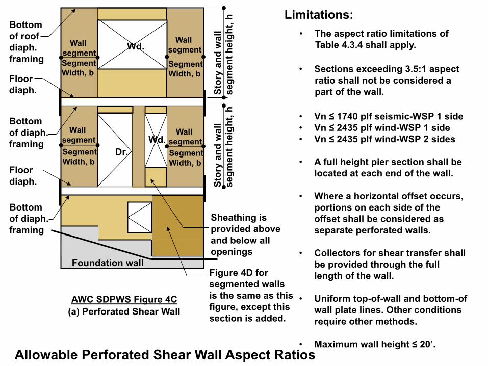
(a) Perforated Shear Wall
AWC SDPWS Figure 4C
Bottom
of roof
diaph.
framing
Floor
diaph.
Floor
diaph.
Bottom
of diaph.
framing
Bottom
of diaph.
framing
Segment
Width, b
Sto
ry a
nd
wa
ll
se
gm
en
t h
eig
ht,
h
Wd.
Wd.
Dr.
Wall
segment
Segment
Width, b
Wall
segment
Segment
Width, b
Wall
segment
Segment
Width, b
Wall
segment
Sto
ry a
nd
wa
ll
se
gm
en
t h
eig
ht,
h
Sheathing is
provided above
and below all
openings
Figure 4D for
segmented walls
is the same as this
figure, except this
section is added.
Foundation wall
Allowable Perforated Shear Wall Aspect Ratios
• Sections exceeding 3.5:1 aspect
ratio shall not be considered a
part of the wall.
• The aspect ratio limitations of
Table 4.3.4 shall apply.
• Vn ≤ 1740 plf seismic-WSP 1 side
• Vn ≤ 2435 plf wind-WSP 1 side
• Vn ≤ 2435 plf wind-WSP 2 sides
• A full height pier section shall be
located at each end of the wall.
• Where a horizontal offset occurs,
portions on each side of the
offset shall be considered as
separate perforated walls.
• Collectors for shear transfer shall
be provided through the full
length of the wall.
• Uniform top-of-wall and bottom-of
wall plate lines. Other conditions
require other methods.
• Maximum wall height ≤ 20’.
Limitations:

Maximum Shear @ full hgt. sect.
Sheathingarea ratio
Empirically determined shear resistance reduction factors, C0 – based on maximum opening height and percentage of full height wall segments.
Sugiyama Method-Reduced shear capacity is multiplied by the full length of the wall.
APA, IBC, SDPWS Method- Reduced shear capacity is multiplied by the sum of the lengths of the full height sections (slightly more conservative).
Hdr
Opening
Hdr
Max
. ope
ning
hei
ght
vmax
Tint
V
Wall segment
Wall segment
Wall segment
h m
ax=2
0 ft
Li (typ) Li (typ)Li (typ)
Vallow = (v Tabular ) x (CO) x ∑LiWhere:
Per SDPWS Table 4.3.3.5!" =
$% − '$
()*)+(,
$ = -- + /"
0+(,A0 = total area of openings
Hold down at ends
1234 = 5
!* ∑(,
1234 = 7,8) = 5!"+(,
7 = ! = 50!"+(9
At full-hgt. segments
CCC
C
C
AWC Section 4.3.6.1.3Each end of each segment shall be designed for the compression force C.
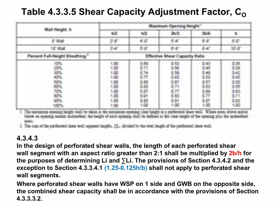
Table 4.3.3.5 Shear Capacity Adjustment Factor, CO
In the design of perforated shear walls, the length of each perforated shear wall segment with an aspect ratio greater than 2:1 shall be multiplied by 2b/h for the purposes of determining Li and ∑Li. The provisions of Section 4.3.4.2 and the exception to Section 4.3.3.4.1 (1.25-0.125h/b) shall not apply to perforated shear wall segments. Where perforated shear walls have WSP on 1 side and GWB on the opposite side, the combined shear capacity shall be in accordance with the provisions of Section 4.3.3.3.2.
4.3.4.3
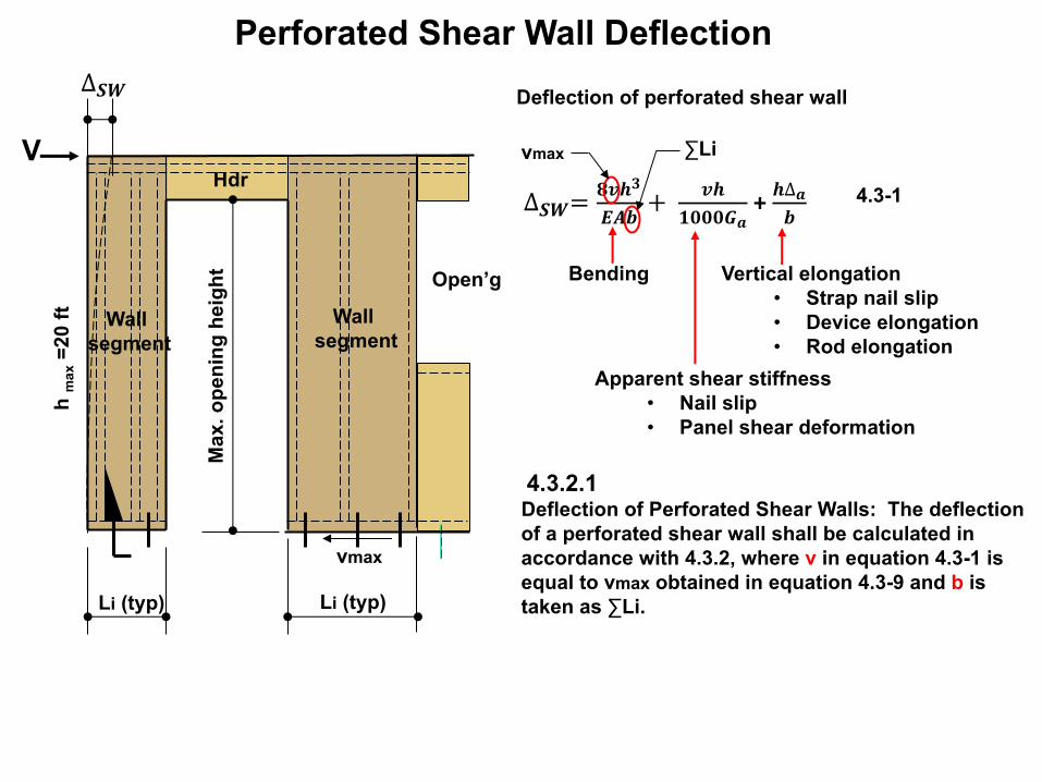
Perforated Shear Wall Deflection
Vertical elongation• Strap nail slip• Device elongation• Rod elongation
Bending
Apparent shear stiffness• Nail slip• Panel shear deformation
Deflection of perforated shear wall
4.3-1
4.3.2.1 Deflection of Perforated Shear Walls: The deflection of a perforated shear wall shall be calculated in accordance with 4.3.2, where v in equation 4.3-1 is equal to vmax obtained in equation 4.3-9 and b is taken as ∑Li.
∆"#= %&'()*+ +
&'-.../0
+ '∆0+
vmax ∑Li
Open’g
Hdr
Max
. ope
ning
hei
ght
vmax
V
Wall segment
Wall segment
h m
ax=2
0 ft
Li (typ)Li (typ)
∆"#

3’ 6’ 5.5’14.5’
4’
3’
2’
1 2
A
B
3
C
D
4
9’
4500 lbw=200 plf
(See recent Testing-APA Form M410 and T555)
Tie straps as required to develop the corner forces into the wall Anchor bolts
or nails
(Typical boundary Member)
Typical boundary member
2’ min. per SDPWS Section 4.3.5.2(2008 requirement)
Many examples ignore gravity loads
FTAO Shear Walls
Cont. Rim joist
Strut/collector
Shear panelsor blocking
(Diekmann)-Vierendeel Truss/Frame
https://www2.strongtie.com/webapps/sitebuiltshearwalldesigner/https://www.apawood.org/ftao
TDAlt.ld.path
A/R
A/R
A/R
A/R

(b) Force Transfer Around Opening
Wall
pier
Wall
pier
Wall
pier
Wall
pier Wall
pier
Wa
ll P
ier
he
igh
t
Wa
ll p
ier
he
igh
t
Wall
pier
width
Cle
ar
he
igh
t
Wa
ll p
ier
he
igh
t
Overall width
AWC SDPWS Figure 4E
Dr.
Wall
pier
width
Boundary
members
Collector (typ.)
Foundation wall
Allowable Shear Wall Aspect Ratios For FTAO Shear Walls
Note: Not
shown as
having to
comply w/
A/R
Wd.
Wd.
• The aspect ratio limitations of
Table 4.3.4 shall apply to the
overall wall and the pier sections
on each side of the openings
• Minimum pier width=2’-0”.
• A full height pier section shall be
located at each end of the wall.
• Where a horizontal offset occurs,
portions on each side of the
offset shall be considered as
separate FTAO walls.
• Collectors for shear transfer shall
be provided through the full
length of the wall.
Limitations:
ATC 7, Diekmann, FPInnovations
If the sections above, below or on each side of the opening does not meet
code aspect ratio limits it should be
ignored (not stiff enough).
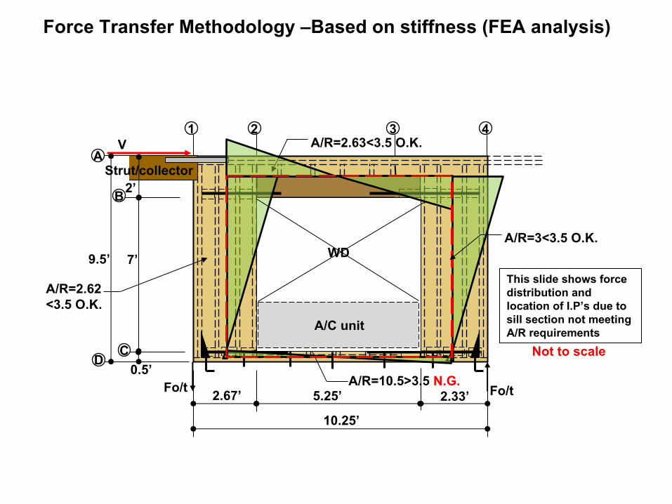
2.67’ 5.25’ 2.33’
10.25’
7’
0.5’
2’
1 2
A
B
3
CD
4
9.5’
V A/R=2.63<3.5 O.K.
A/R=2.62<3.5 O.K.
A/R=10.5>3.5 N.G.
A/R=3<3.5 O.K.
Fo/t
Force Transfer Methodology –Based on stiffness (FEA analysis)
This slide shows force distribution and location of I.P’s due to sill section not meeting A/R requirements
Not to scale
A/C unit
WD
Strut/collector
Fo/t
V
C
1 2
A
3
D
4
T
F=0 lb
F=0 lbF=0 lb
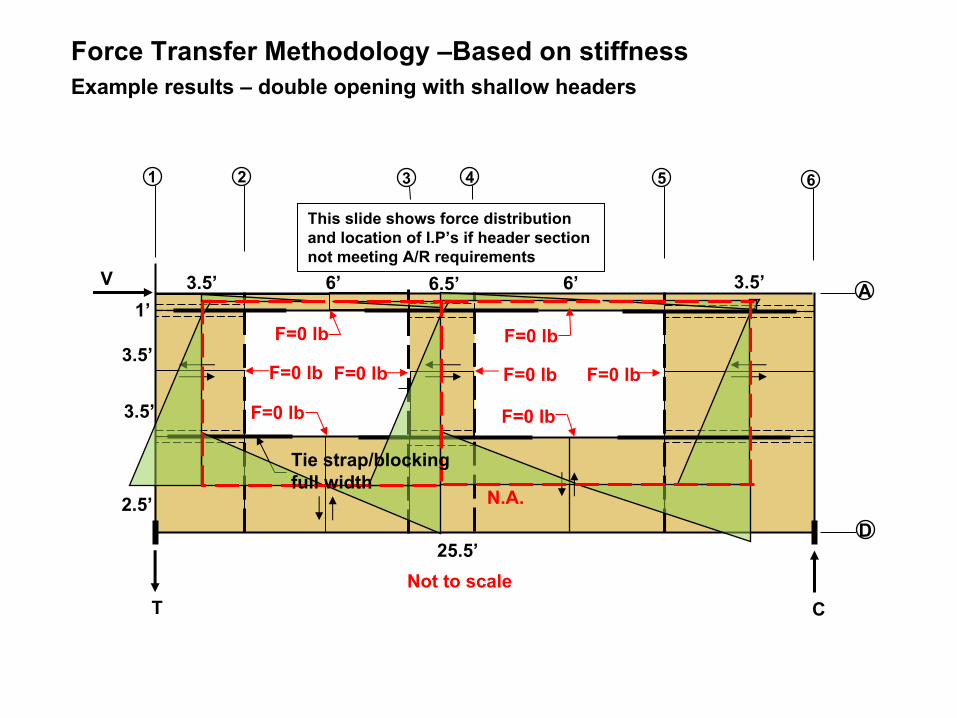
Force Transfer Methodology –Based on stiffness
F=0 lb
5 6
6’6.5’6’3.5’ 3.5’
25.5’
1’
3.5’
3.5’
2.5’
F=0 lb
F=0 lbF=0 lb
F=0 lb
This slide shows force distribution and location of I.P’s if header section not meeting A/R requirements
Example results – double opening with shallow headers
Not to scale
Tie strap/blocking full width
N.A.

4500
C
Tie strap/blocking full width
Blocking
Point of inflection is assumed to occur at mid-length (Typ.)
MM
V
V
V
V
M
M
1 2
A
B
3
C
D
4
CA B D
F
E
H GI
L
J
K
T
V
V
M
M
F=0 lb
F=0 lbF=0 lb
M
F=0
MF=0 Force Transfer Methodology (Diekmann)-Vierendeel Truss/Frame
F=0 lb
FF
Gravity loads to wall
1343.1 4243.1
w=200 plf
N.A.
Example Cont.
MM
V
V
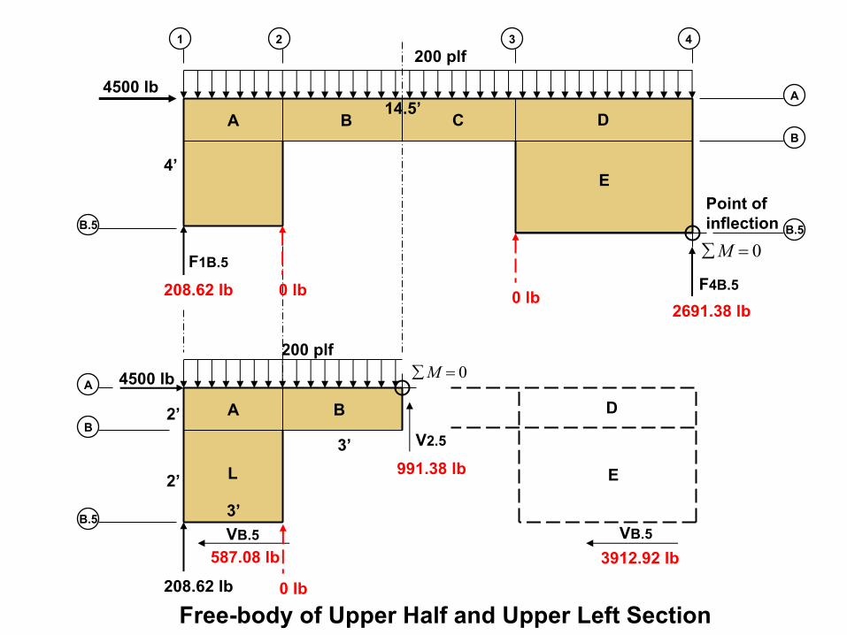
4500 lb
4’
14.5’
208.62 lb
208.62 lb
991.38 lb
587.08 lb
F1B.5
VB.5
1 2
A
B
3
A
B
4
2’
2’
4500 lb
200 plf
200 plf0=åM
0=åMB.5
B.5
2691.38 lbF4B.5
3912.92 lbVB.5
BA C
A D
E
B
D
E
V2.53’
3’
Free-body of Upper Half and Upper Left Section
Point of inflection B.5
0 lb 0 lb
0 lb
L
A
L
K
B
I
587.08
VB=587.08
VB.5=587.08 (587.08)
Vc=587.08
587.08
V2.
5
1551
.7
V2
(1343.1)
3’
3’
F2b(V)391.39
F2C(v)391.39
991.
38
V2
391.
39
(208.62)
F2A
F2B(H)
1381
1037.1
1160.3
F2C(H)
F1B600
F1C182.77
J
(0)
(0)
573.23
2’
2’
2’
1 2
0=åM
0=åM0=åM
0=åM
0=åM
0=åM
Units are in lb
Corner tie strap force
Corner tie strap force
DC
F
E
GH
1591
.38
(991
.38)
V3
268.8
1937.1
1551
.7
1551
.7
236.17
3676.6
V3
(4243.1)
(2691.38)VB.5=3912.92
VB=3912.92
3912.92
(3912.92)
VC=3912.92
3912.92
(0)
5.5’
3’
2’
2’
2’
F3(V)1422.88
F3B(V)1422.9
F4B1268.5
F4C4114.3
F3C(H)
F3B(H)
F3A A
B
3
C
D
4
0=åM
0=åM
0=åM
3’ 3’
3’ 3’
2.5
B.5 B.5
2124.9
1551.7
(4500)
(4500)
F2.5A1274.9
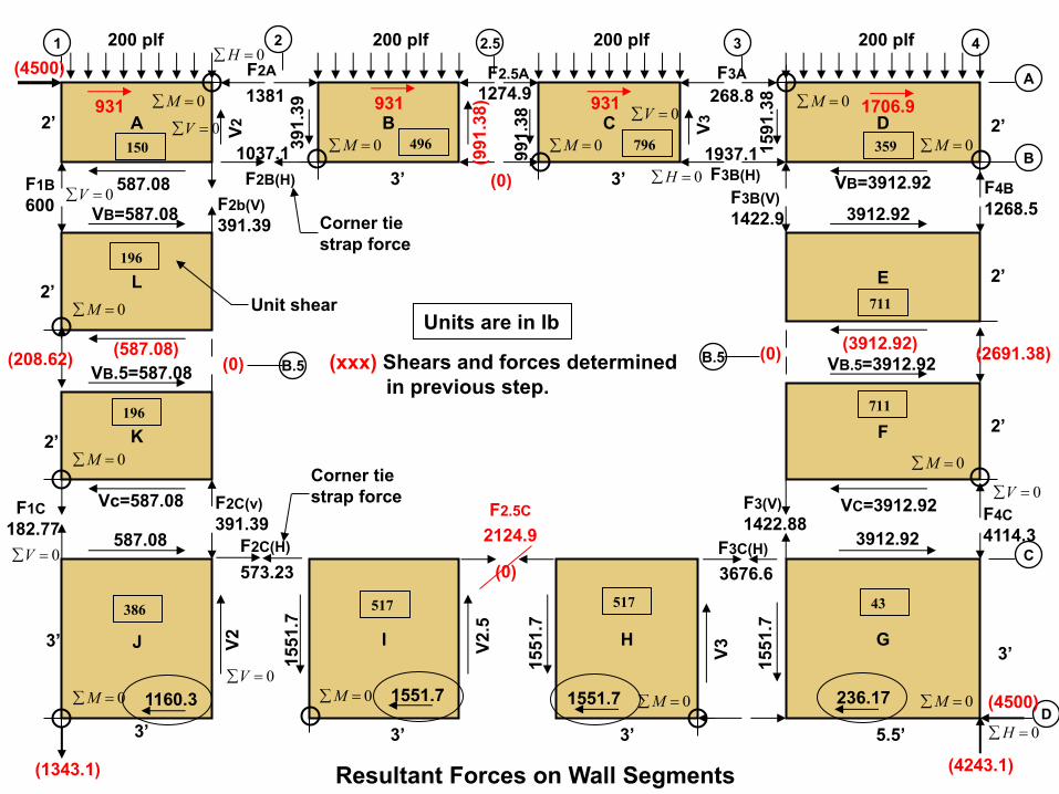
(xxx) Shears and forces determined in previous step.
0=åM
0=åM 0=åM
200 plf 200 plf 200 plf 200 plf
F2.5C
Resultant Forces on Wall Segments
0=åV
0=åH
0=åV
0=åV
0=åV0=åV
0=åH
0=åV
0=åH
1551.7
1706.9931931931
(0)
Unit shear
196
150 496 796
196
386 517 517 43
359
711
711
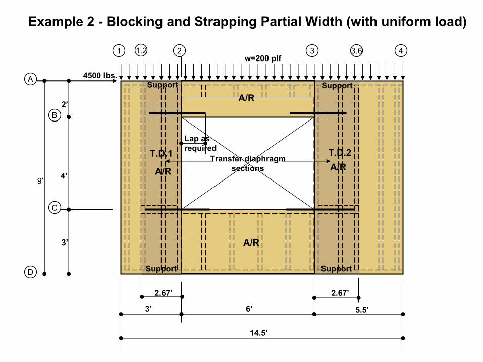
Transfer diaphragmsections
3’ 6’ 5.5’
14.5’
4’
3’
2’
1 2
A
B
3
C
D
4
T.D.2T.D.1
2.67’ 2.67’
9’
3.6
Example 2 - Blocking and Strapping Partial Width (with uniform load)
4500 lbs.
Support
Support
Support
Support
1.2w=200 plf
Lap as required
A/R
A/R
A/R
A/R
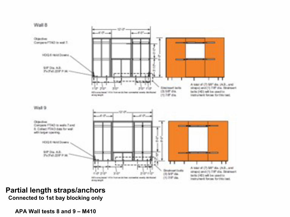
Partial length straps/anchorsConnected to 1st bay blocking only
APA Wall tests 8 and 9 – M410

Blocking at corners
Anchor location
Partial length straps/anchorsConnected to 1st bay blocking only
APA Wall tests 8 and 9 – M410
Photo credit APA:
Wall 8 – IMG_1297
Wall 9 – IMG_1667100_0018100_0021
4243.1 lbs.
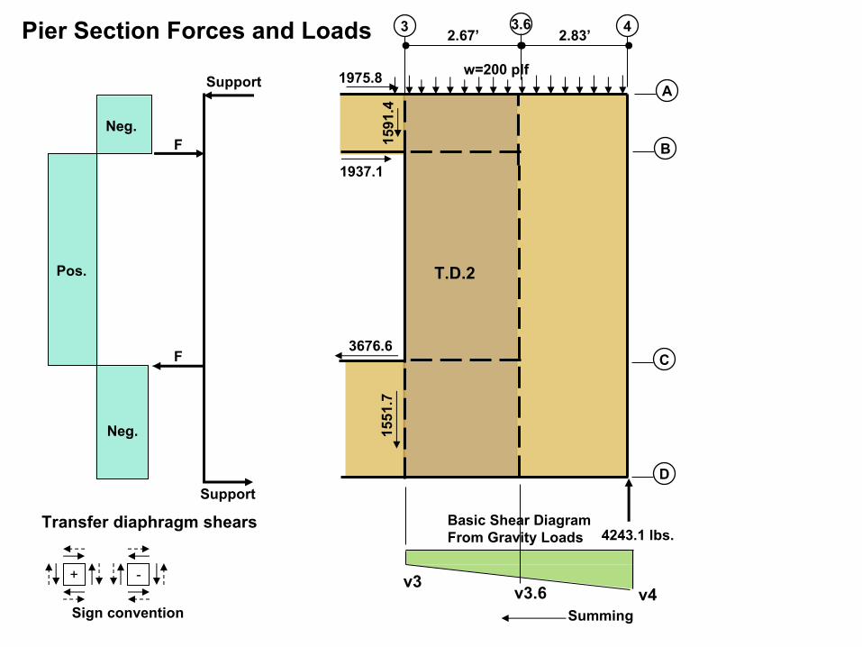
Pier Section Forces and Loads 2.67’
-+
A
B
3
C
D
4
T.D.2
Sign convention
1937.1
1975.8
2.83’
Support
Support
F
F
3676.6
Neg.
Pos.
Neg. 1551
.715
91.4
v3.6 v4v3
Basic Shear DiagramFrom Gravity Loads
Summing
w=200 plf
Transfer diaphragm shears
3.6
3676.6 lbs.
1551
.7
4243.1 lbs.
1937.1 lbs.
Transfer Diaphragm Shears and Net Shears
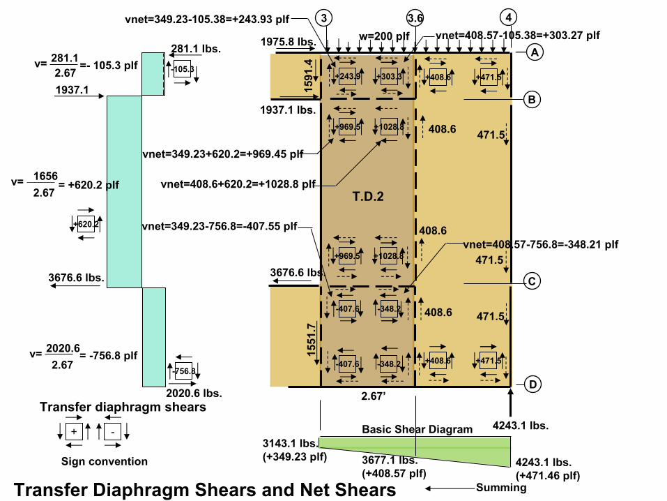
2.67’
-+
1937.1
3676.6 lbs.
281.1 lbs.
2020.6 lbs.
v= 281.12.67
=- 105.3 plf
v= 1656
2.67= +620.2 plf
v= 2020.6
2.67= -756.8 plf
-105.3
-756.8
+620.2
+471.5+408.6
A
B
3
C
D
4
T.D.2
Sign convention
Transfer diaphragm shears
1591
.4
vnet=349.23-105.38=+243.93 plf
vnet=349.23+620.2=+969.45 plf
vnet=349.23-756.8=-407.55 plf
1975.8 lbs.
3.6
+303.3+243.9
+1028.8+969.5
+1028.8+969.5
-348.2-407.6
-348.2-407.6 +471.5+408.6
3677.1 lbs.(+408.57 plf)
4243.1 lbs.(+471.46 plf)
3143.1 lbs.(+349.23 plf)
Basic Shear Diagram
Summing
vnet=408.57-105.38=+303.27 plf
vnet=408.6+620.2=+1028.8 plf
vnet=408.57-756.8=-348.21 plf
408.6
408.6
408.6
471.5
471.5
471.5
w=200 plf

4243.1 lbs.Horizontal Collector Forces
2.67’
-+
A
B
3
C
D
4
T.D.2
Sign convention
C
T969.45
969.5
407.55
1028.81937.1
3676.6
243.9 303.3
348.2
1028.8
243.9 303.3 408.6 471.5
! = #$%&. # ()*.
! = %+&+. + ()*.
! = #$&,. - ()*.
1975.8 2.83’
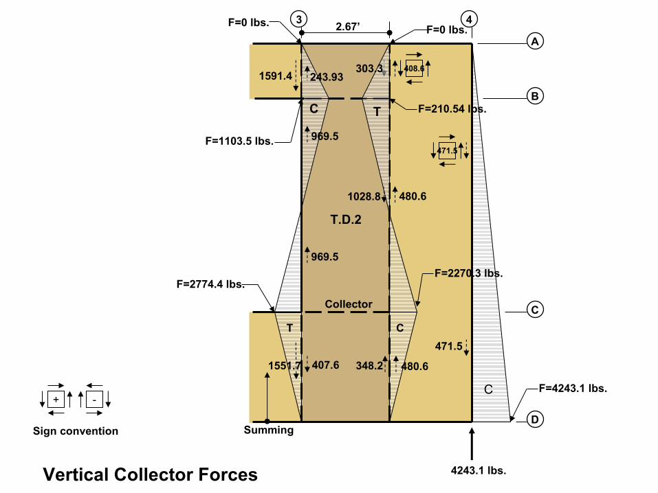
4243.1 lbs.Vertical Collector Forces
2.67’
-+
408.6
471.5
A
B
3
C
D
4
T.D.2
Sign convention
F=1103.5 lbs.
F=2774.4 lbs.
T
348.2
1591.4
407.61551.7
1028.8
969.5
969.5
303.3
F=0 lbs.
Summing
F=2270.3 lbs.
F=210.54 lbs.
F=0 lbs.
F=4243.1 lbs.
480.6
C
C
T
Collector
243.93
480.6
471.5
C
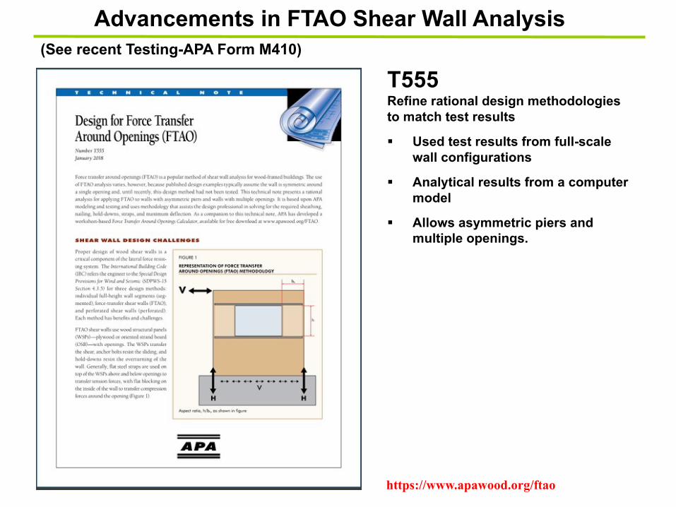
(See recent Testing-APA Form M410)
Advancements in FTAO Shear Wall Analysis
T555Refine rational design methodologies to match test results
§ Used test results from full-scale wall configurations
§ Analytical results from a computer model
§ Allows asymmetric piers and multiple openings.
https://www.apawood.org/ftao

20’-0”L
5’-0”L1
4’-0”L2
2’-6”L3
6’-0”LO1
2’-6”LO2
4’-8
”ho
2
8’-0
”H
4000 lbs.
V
1’-4
”ha
2’-0
”hb
2
1600
1600
2’-8
”ho
14’
-0”
hb1
TD
Multi-story walls?Tall shear walls?
What happens when different depths?
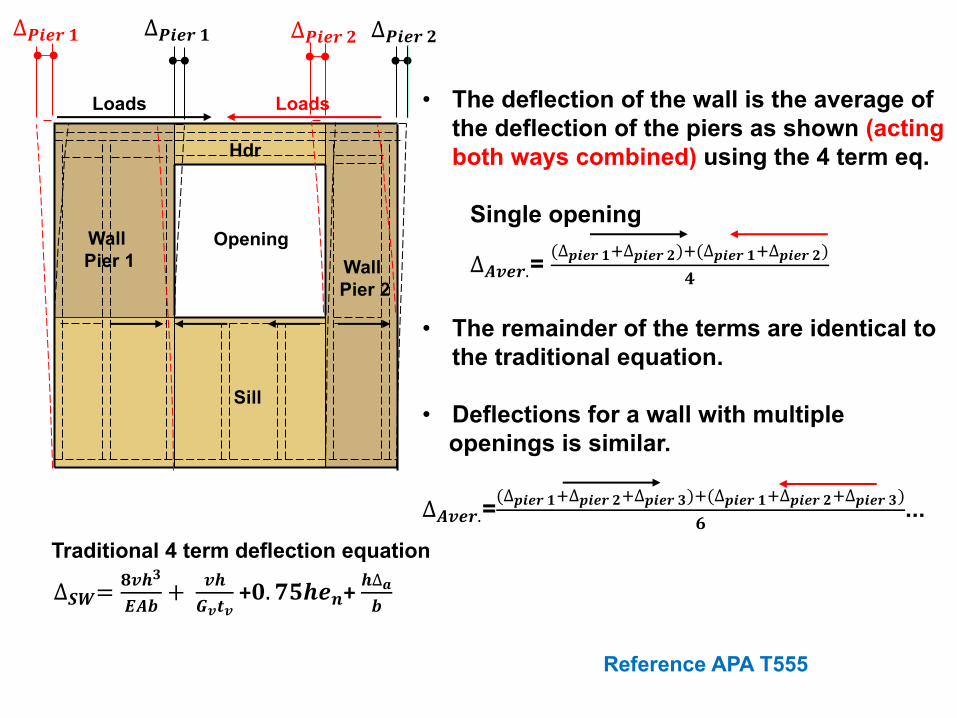
• The deflection of the wall is the average of the deflection of the piers as shown (acting both ways combined) using the 4 term eq.
Single opening
∆"#$%.= (∆()$% *+∆()$% ,)+(∆()$% *+∆()$% ,).
• The remainder of the terms are identical to the traditional equation.
• Deflections for a wall with multiple openings is similar.
∆"#$%.=(∆()$% *+∆()$% ,+∆()$% /)+(∆()$% *+∆()$% ,+∆()$% /)
0 ...
Hdr
Opening Wall Pier 2
Wall Pier 1
Sill
∆12= 4#5/6"7 +
#59#:#
+;. <=5$>+ 5∆?7
Traditional 4 term deflection equation
∆@)$% * ∆@)$% ,
Reference APA T555
Loads Loads
∆@)$% * ∆@)$% ,

Let’s Take a 10 Minute Break
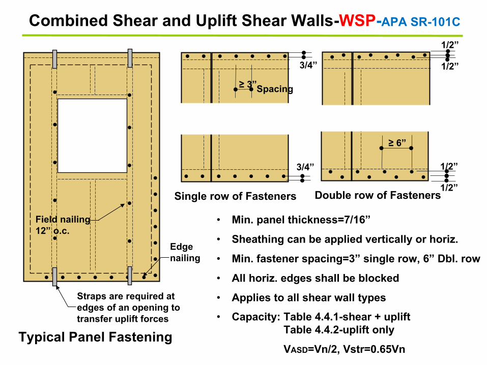
Combined Shear and Uplift Shear Walls-WSP-APA SR-101C
. . . . . . .
. . . . . . .
. . . . . . . .
. . . . . . . .
Typical Panel Fastening
Single row of Fasteners Double row of Fasteners
.
.
.
.
.
.
.
.
.
.
. . . . . . . . .
. .
. .
.
• Min. panel thickness=7/16”
• Sheathing can be applied vertically or horiz.
• Min. fastener spacing=3” single row, 6” Dbl. row
• All horiz. edges shall be blocked
• Applies to all shear wall types
• Capacity: Table 4.4.1-shear + upliftTable 4.4.2-uplift only
VASD=Vn/2, Vstr=0.65Vn
Edge nailing
Field nailing12” o.c.
Spacing
≥ 6”
≥ 3”
3/4” 1/2”
1/2”
1/2”
1/2” 3/4”
Straps are required at edges of an opening to transfer uplift forces

SW1 SW4
W ( plf)1 2
A
B
Diaphragm support
Diaphragmsupport
Stable
SW3
SW2
SW1 SW4
W ( plf)1 2
A
B
Diaphragm support
Diaphragmsupport
SW3
SW2
Unstable
Acts like open front diaphragm(SDPWS 4.2.5.2)
No support
Shear walls are parallel to applied loads
Not all shear walls are parallel to applied loads
Angled/Skewed Shear WallsNo Angled/Skewed Shear Wall Testing

Structure is stable
P-delta problem. Wall deflects too much out-of-plane, which causes rotation in the diaphragm(Acts like open front diaphragm-shifts forces to side walls)
Large deflection
Wall warpsand translates
Concentric steel braced frame or shear walls both sides of the building-resist rotational forces.
Diaphragm rotates
Diaphragm with Angle Shear Wall-Horizontal Type 5 Irregularity Transverse Loading
Wall stiffness(SW1 & longit. walls)
DiaphragmSW2
Structural Model
Top of wall braces
24’SW1
C.L.
1
A
B
SW support
θ
θθθθ =!"#
=$"#=%"#=&'#

SW1
Effe
ctiv
e w
idth
1
A
BDiaphragm support
C.R.
A
BDiaphragm support
Hold down
Hold down
Effective width
SW1
TD1
SW1
Effe
ctiv
e w
idth Cantilever
section TD1
No Circular Shear Wall Testing
WSP thickness depends on radius
Circular Shear Walls

Source: nees.org
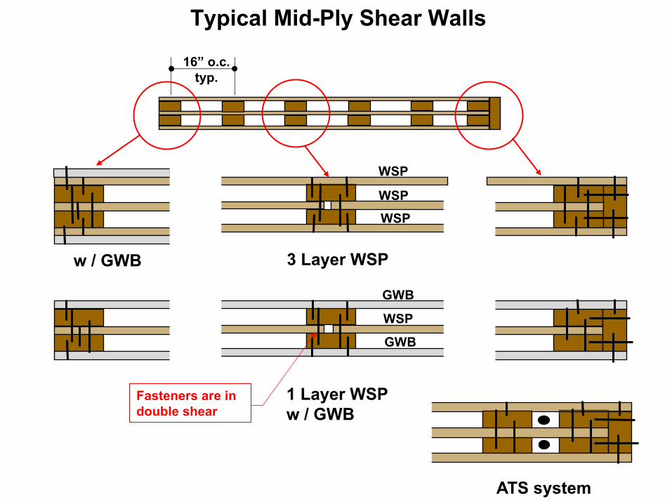
Mid-Ply Shear Walls
¡ Test Results:
• Mid-ply walls 2.4 to 2.8 x stiffer than standard shear walls monotonic loading.
• Mid-ply walls 1.8 to 2.2 x stiffer than standard shear walls cyclic loading.
• Better energy dissipaters, 3 to 5x better than standard shear walls
¡ Mid-ply walls:• Carry high shear demand
• Reduce torsional effects
WSP
WSP
WSP
WSP
GWB
GWB
ATS system
Typical Mid-Ply Shear Walls
Fasteners are in double shear
16” o.c. typ.
3 Layer WSP
1 Layer WSPw / GWB
w / GWB

Prescriptive / Proprietary Portal Frames
Prescriptive Code Portal Frames Proprietary Portal
Frames IBC 2308.9.3.2
Source: strongtie.com
Truss Walls
Truss Frames
Hybrid Wood/Steel Proprietary Systems

Shear Wall Design
• Shear Wall Types
• Shear wall Anchorage
• SDPWS Code Requirements
• Complete Load Paths
• ASCE 7 Offset Shear Wall Requirements
• Offset Shear Walls
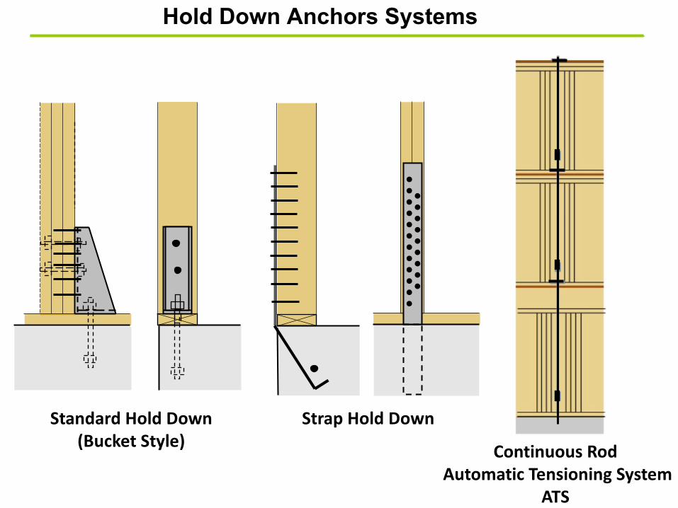
Hold Down Anchors Systems
Standard Hold Down (Bucket Style)
Strap Hold Down
…………
………
Continuous RodAutomatic Tensioning System
ATS
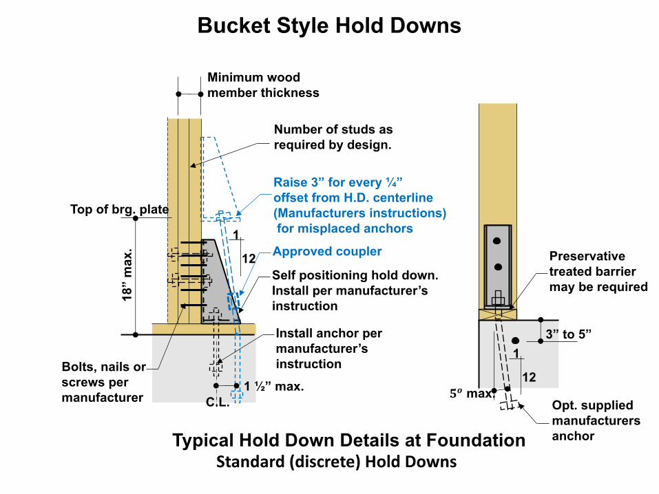
Typical Hold Down Details at Foundation
1
12
18”
max
.
Bolts, nails or screws per manufacturer
Self positioning hold down. Install per manufacturer’s instruction
Raise 3” for every ¼” offset from H.D. centerline(Manufacturers instructions)for misplaced anchors
C.L.
Install anchor per manufacturer’s instruction
Number of studs as required by design.
1
12!" max.1 ½” max.
Top of brg. plate
Approved coupler Preservative treated barrier may be required
Minimum wood member thickness
3” to 5”
Standard (discrete) Hold Downs
Bucket Style Hold Downs
Opt. supplied manufacturers anchor
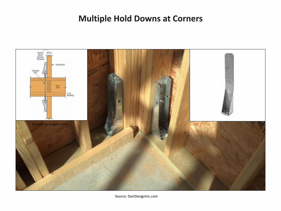
Multiple Hold Downs at Corners
Source: DartDesignInc.com
Source: strongtie.com

Hold downs installed at an angle
Field Installation Issues
Large knots
Courtesy of Willdan Engineering

Hold down misplaced.Sheathing is removed.
Field Installation IssuesCourtesy of Willdan Engineering
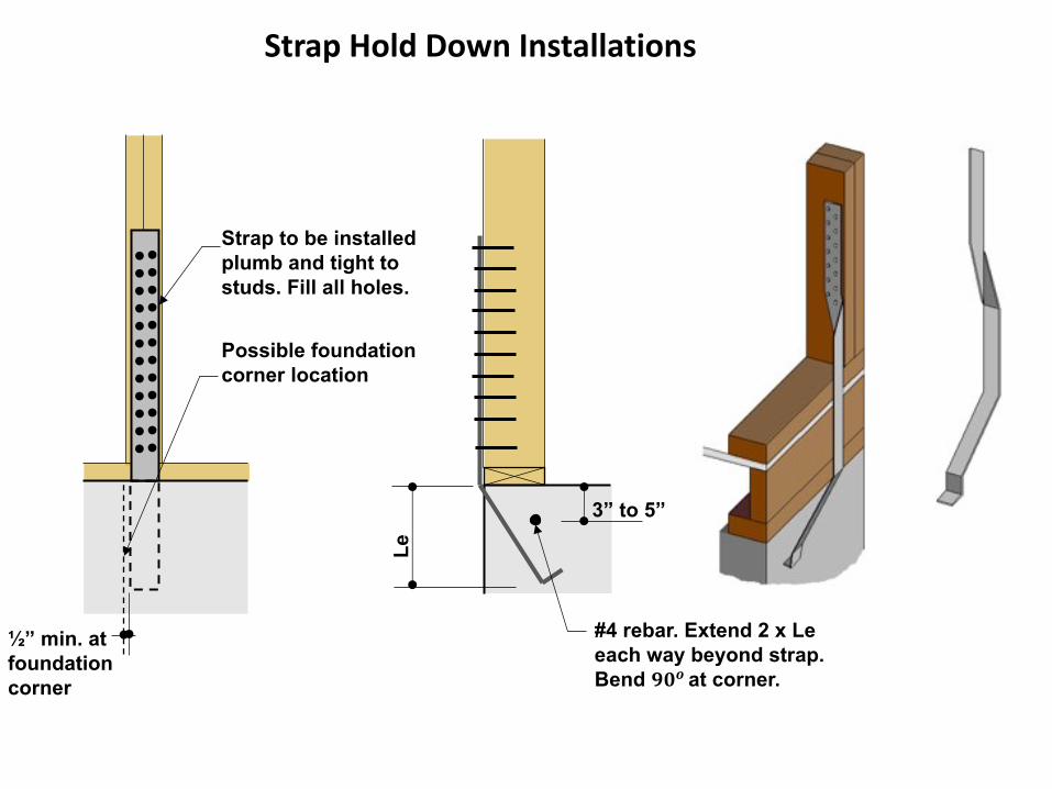
Strap to be installed plumb and tight to studs. Fill all holes.
#4 rebar. Extend 2 x Le each way beyond strap.Bend !"# at corner.
3” to 5”
Le
½” min. at foundationcorner
Possible foundation corner location
Strap Hold Down Installations
…………
…………
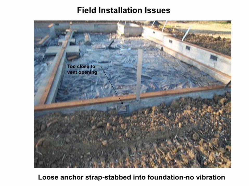
Loose anchor strap-stabbed into foundation-no vibration
Too close to vent opening
Field Installation Issues
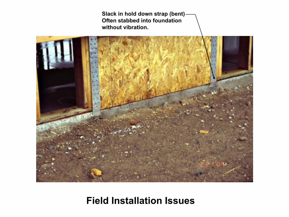
Slack in hold down strap (bent)Often stabbed into foundation without vibration.
Field Installation Issues
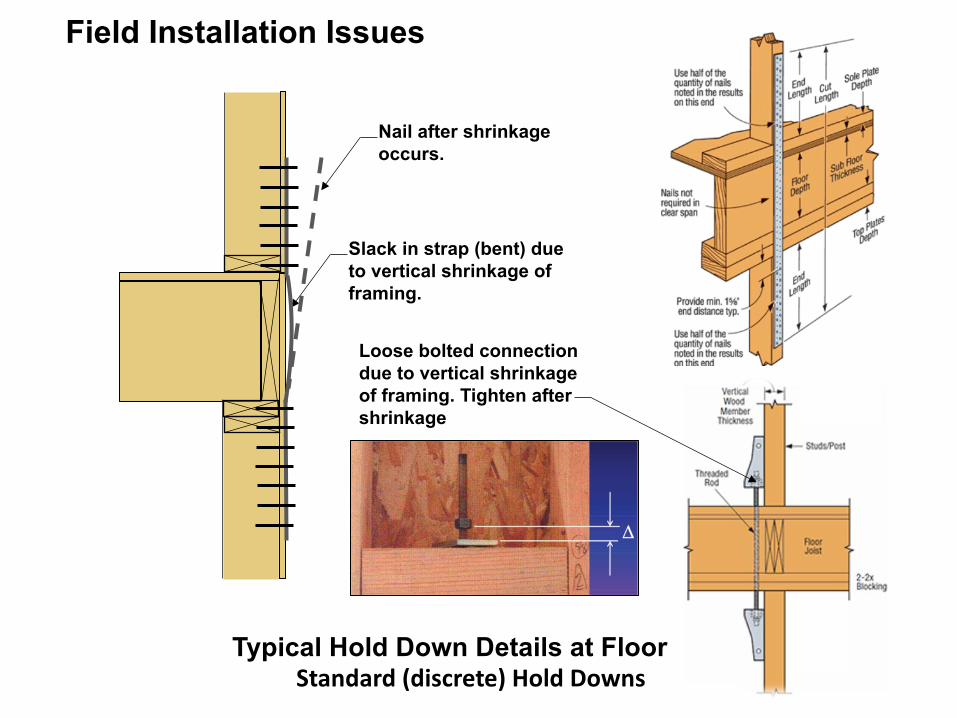
Slack in strap (bent) due to vertical shrinkage of framing.
Field Installation Issues
Typical Hold Down Details at FloorStandard (discrete) Hold Downs
Loose bolted connection due to vertical shrinkage of framing. Tighten after shrinkage
Nail after shrinkageoccurs.
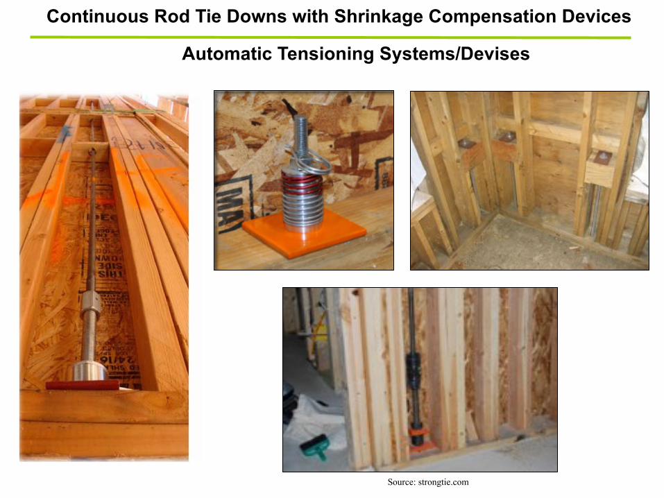
Continuous Rod Tie Downs with Shrinkage Compensation Devices
Source: strongtie.com
Automatic Tensioning Systems/Devises
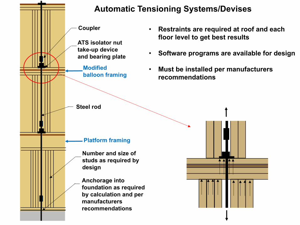
ATS isolator nut take-up deviceand bearing plate
Coupler
Steel rod
Modifiedballoon framing
Platform framing
Automatic Tensioning Systems/Devises
• Restraints are required at roof and each floor level to get best results
• Software programs are available for design
• Must be installed per manufacturers recommendations
Number and size of studs as required by design
Anchorage into foundation as required by calculation and per manufacturers recommendations

4 kips
Automatic Tensioning Systems/Devises
27 kips
14 kips(27 kips)Full hgt.
2 kips2 kips
7 kips 7 kips
13.5 kips 13.5 kips
Tied off at roof only• Lack of redundancy• Increased costs• Increased drift• Single device must
accommodate shrinkage at all floors
Tied off at roof and all floors• Accommodates
shrinkage at each floor• Greater redundancy• Reduced drift• Lower costs (Can be
subjective)
Legendxx kips Tied off at each floor(xx kips) Tied off at roof only
Tied off at each floorTied off at roof only
Skipped floor
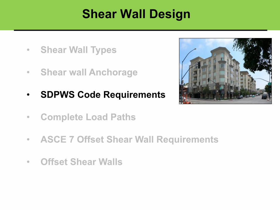
Shear Wall Design
• Shear Wall Types
• Shear wall Anchorage
• SDPWS Code Requirements
• Complete Load Paths
• ASCE 7 Offset Shear Wall Requirements
• Offset Shear Walls
2015 SDPWS
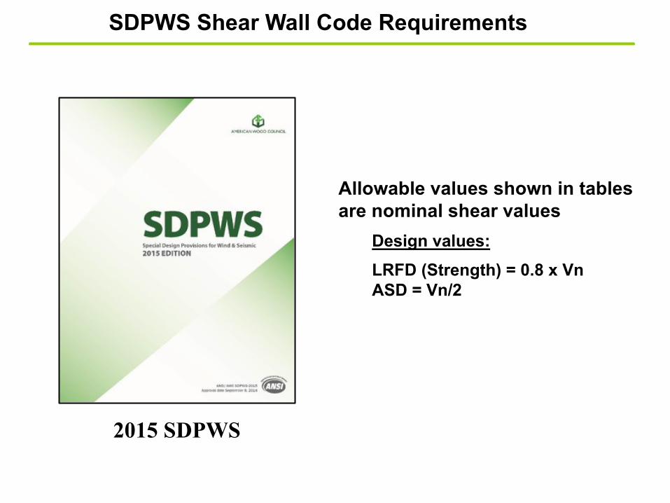
SDPWS Shear Wall Code Requirements
Allowable values shown in tables are nominal shear values
Design values:LRFD (Strength) = 0.8 x VnASD = Vn/2
SheathingMaterial
MinimumNominal
PanelThickness
(in.)
MinimumFastener
PenetrationIn Framing
Member or Blocking
(in.)
FastenerType & Size
ASeismic
Panel Edge Fastener Spacing (in.)
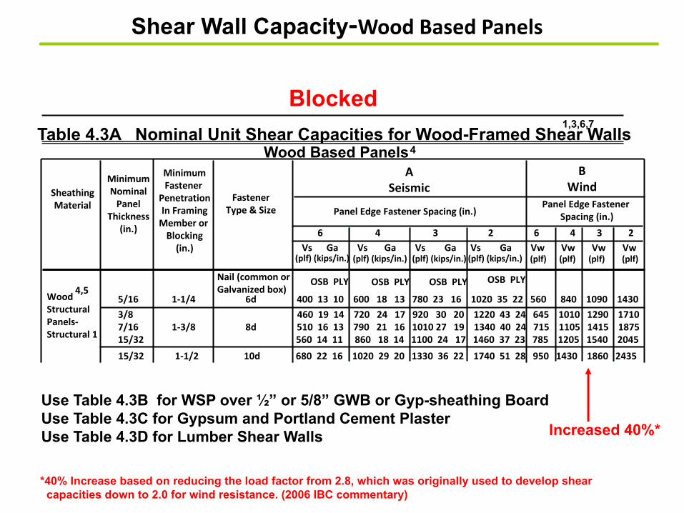
Table 4.3A Nominal Unit Shear Capacities for Wood-Framed Shear Walls
6 4 3 2 6 4 3 2 Vs Ga Vs Ga Vs Ga Vs Ga Vw Vw Vw Vw
1,3,6,7
5/16 1-1/4 6d 400 13 10 600 18 13 780 23 16 1020 35 22 560 840 1090 1430
BWind
Panel Edge Fastener Spacing (in.)
Wood Based Panels4
(plf) (kips/in.) (plf) (kips/in.)(plf) (kips/in.)(plf) (kips/in.) (plf) (plf) (plf) (plf)
Nail (common orGalvanized box)
Wood Structural Panels-Structural 1
Use Table 4.3B for WSP over ½” or 5/8” GWB or Gyp-sheathing BoardUse Table 4.3C for Gypsum and Portland Cement PlasterUse Table 4.3D for Lumber Shear Walls
OSB PLY OSB PLY OSB PLY OSB PLY4,5
3/8 460 19 14 720 24 17 920 30 20 1220 43 24 645 1010 1290 17107/16 1-3/8 8d 510 16 13 790 21 16 1010 27 19 1340 40 24 715 1105 1415 1875 15/32 560 14 11 860 18 14 1100 24 17 1460 37 23 785 1205 1540 2045 15/32 1-1/2 10d 680 22 16 1020 29 20 1330 36 22 1740 51 28 950 1430 1860 2435
Increased 40%*
Blocked
Shear Wall Capacity-Wood Based Panels
*40% Increase based on reducing the load factor from 2.8, which was originally used to develop shear capacities down to 2.0 for wind resistance. (2006 IBC commentary)

Supported Edges
UnblockedTable 4.3.3.3.2 Unblocked Shear Wall Adjustment Factor, Cub
Intermediate Framing
Stud Spacing (in.)12 16 20 24
6 12 0.8 0.6 0.5 0.46 6 1.0 0.8 0.6 0.5
vub= vb Cub Eq. 4.3-2
vub = Nominal unit shear value for unblocked shear wall
vb = Use nominal shear values from Table 4.3A for blocked WSP shear walls with stud spacing at 24” o.c. and 6” o.c nailing
Shear Wall Capacity-Wood Based Panels

Summing Shear Capacities-4.3.3.3
Same material, constructionand same capacities(can double Ga)
Dissimilar materials(Not cumulative)
Dissimilar materials
Vallow = largest
Vallow=2x
Vallow =2x smaller orlargest, greater of.
VS1
VS2Same material, construction on both sides, different capacities-Seismic
Side 1
Vsc
Side 2
!"# = !"% + !"'()* = +,-.!"# Combined apparent shear wall shear
capacity (seismic)
+,-. = ()%!"%
/0 ()'!"'
Minimum of
Where:
(Exception-for wind,add capacities)
Gac= Combined apparent shear wall shear stiffness
Ga1= Apparent shear wall shear stiffness side 1(Ga2 side 2)-from SDPW Tables 4A-4D
vS1=Nominal unit shear capacity of side 1 (vS2 side 2)
VS1
VS2
VS1
Vsc or Vwc
Vsc or Vwc
Vsc or Vwc
Vsc = combined nominal unit shear capacity seismicVwc = combined nominal unit shear capacity windvS1=Nominal unit shear capacity of side 1 (vS2 side 2)
The shear wall deflection shall be calculated using the combined apparent shear wall shear stiffness, Gac and the combined nominal unit shear capacity, vsc, using the following equations:
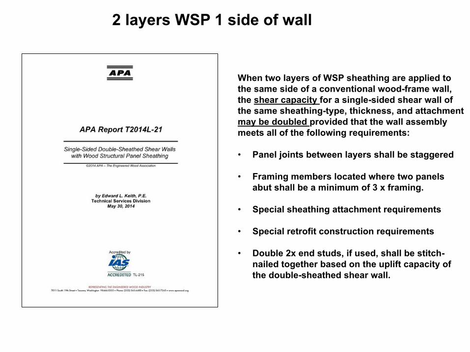
2 layers WSP 1 side of wall
When two layers of WSP sheathing are applied to the same side of a conventional wood-frame wall, the shear capacity for a single-sided shear wall of the same sheathing-type, thickness, and attachment may be doubled provided that the wall assembly meets all of the following requirements:
• Panel joints between layers shall be staggered
• Framing members located where two panels abut shall be a minimum of 3 x framing.
• Special sheathing attachment requirements
• Special retrofit construction requirements
• Double 2x end studs, if used, shall be stitch-nailed together based on the uplift capacity of the double-sheathed shear wall.

Shear Wall A/R Adjustment Factors-SDPWS Section 4.3.4
• WSP’s with A/R > 2:1 multiply Vn x (1.25-0.125h/b)per Section 4.3.4.2.
• Struct. Fiberboard with A/R > 1:1 multiply Vn x (1.09-0.09h/b) per Section 4.3.4.2.
• Accounts for reduced unit shear capacity in high aspect ratio walls due to loss of stiffness as A/R increases.
Capacity Adjustments-Wind and seismic
SegmentedSW
PSW
• Segments with an aspect ratio > 2:1 shall be multiplied by 2b/h for the purposes of determining Li and ∑Li. The provisions of Section 4.3.4.2 and the exceptions to Section 4.3.3.4.1 (equal deflection) shall not apply to perforated shear wall segments.
Justification-Based on tests:
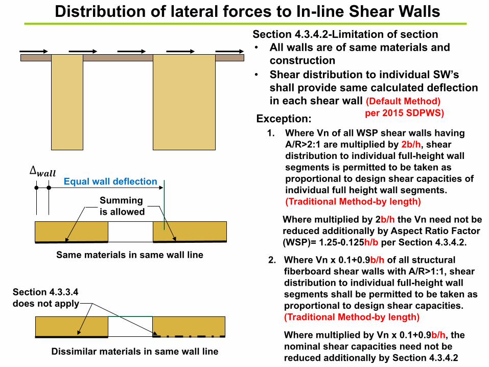
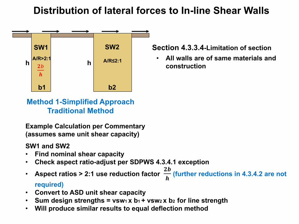
Distribution of lateral forces to In-line Shear Walls
• All walls are of same materials and construction
1. Where Vn of all WSP shear walls having A/R>2:1 are multiplied by 2b/h, shear distribution to individual full-height wall segments is permitted to be taken as proportional to design shear capacities of individual full height wall segments.(Traditional Method-by length)
Where multiplied by 2b/h the Vn need not bereduced additionally by Aspect Ratio Factor(WSP)= 1.25-0.125h/b per Section 4.3.4.2.
Exception:
Section 4.3.4.2-Limitation of section
Same materials in same wall line
Summing is allowed
Dissimilar materials in same wall line
Section 4.3.3.4does not apply
Equal wall deflection∆"#$$
2. Where Vn x 0.1+0.9b/h of all structural fiberboard shear walls with A/R>1:1, sheardistribution to individual full-height wall segments shall be permitted to be taken asproportional to design shear capacities. (Traditional Method-by length)
Where multiplied by Vn x 0.1+0.9b/h, thenominal shear capacities need not be reduced additionally by Section 4.3.4.2
• Shear distribution to individual SW’s shall provide same calculated deflection in each shear wall (Default Method)
per 2015 SDPWS)
Distribution of lateral forces to In-line Shear Walls
• All walls are of same materials and construction
Section 4.3.3.4-Limitation of section
Method 1-Simplified ApproachTraditional Method
b1 b2
SW1 SW2
h
Example Calculation per Commentary(assumes same unit shear capacity)
SW1 and SW2• Find nominal shear capacity• Check aspect ratio-adjust per SDPWS 4.3.4.1 exception
• Aspect ratios > 2:1 use reduction factor !"# (further reductions in 4.3.4.2 are not
required)• Convert to ASD unit shear capacity• Sum design strengths = vsw1 x b1 + vsw2 x b2 for line strength• Will produce similar results to equal deflection method
!$#
A/R>2:1 A/R≤2:1h
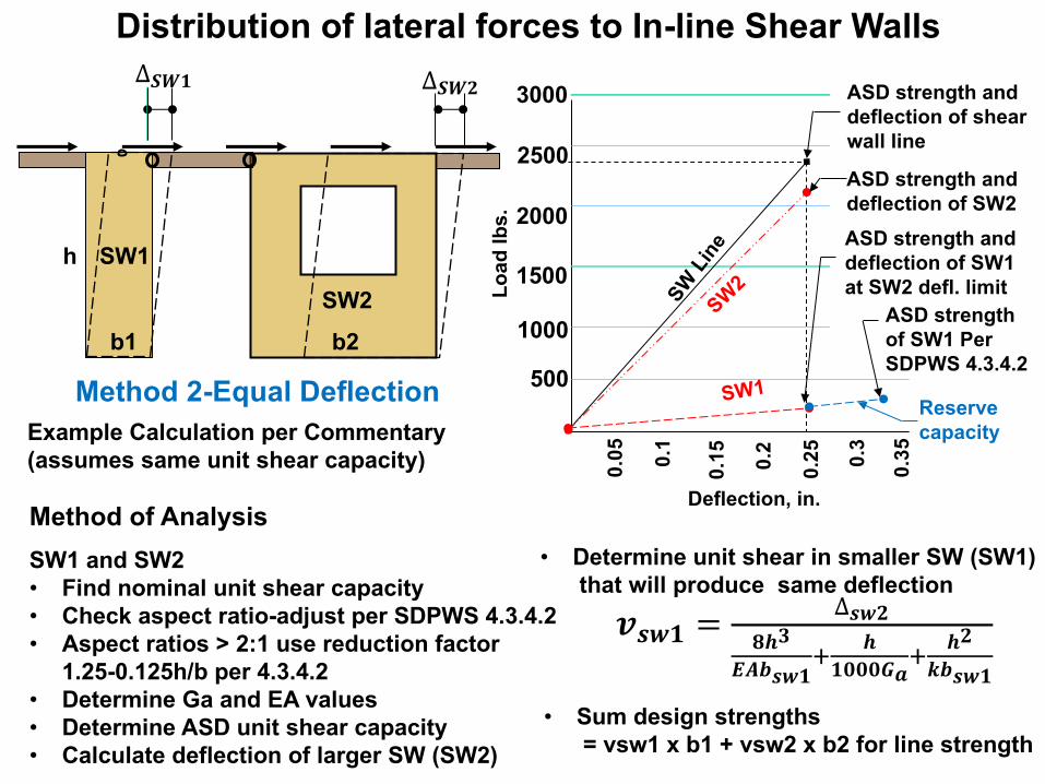
Distribution of lateral forces to In-line Shear Walls
Method 2-Equal Deflection
∆"#$ ∆"#%
b1 b2
SW1
SW2
h
Method of Analysis
SW1 and SW2• Find nominal unit shear capacity• Check aspect ratio-adjust per SDPWS 4.3.4.2• Aspect ratios > 2:1 use reduction factor
1.25-0.125h/b per 4.3.4.2• Determine Ga and EA values• Determine ASD unit shear capacity• Calculate deflection of larger SW (SW2)
&'($ = ∆'(%*+,
-./'($0 +$111230
+%4/'($
• Sum design strengths = vsw1 x b1 + vsw2 x b2 for line strength
Example Calculation per Commentary(assumes same unit shear capacity)
• Determine unit shear in smaller SW (SW1) that will produce same deflection
3000
2500
2000
1500
1000
Load
lbs.
500
SW L
ine
SW2
Deflection, in.
0.350.3
0.250.2
0.150.
1
0.05
ASD strength and deflection of shear wall line
ASD strength and deflection of SW2
ASD strength and deflection of SW1at SW2 defl. limit
ASD strength of SW1 Per SDPWS 4.3.4.2
SW1Reserve capacity
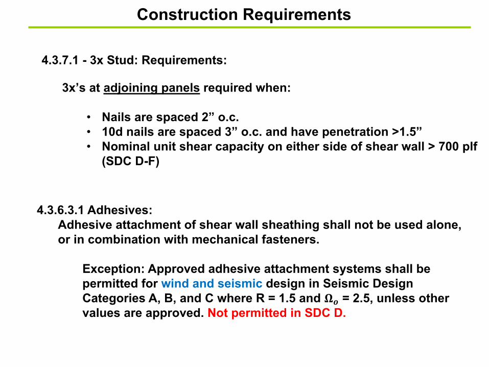
Construction Requirements
3x’s at adjoining panels required when:
• Nails are spaced 2” o.c.• 10d nails are spaced 3” o.c. and have penetration >1.5”• Nominal unit shear capacity on either side of shear wall > 700 plf
(SDC D-F)
4.3.7.1 - 3x Stud: Requirements:
4.3.6.3.1 Adhesives: Adhesive attachment of shear wall sheathing shall not be used alone, or in combination with mechanical fasteners.
Exception: Approved adhesive attachment systems shall be permitted for wind and seismic design in Seismic Design Categories A, B, and C where R = 1.5 and !" = 2.5, unless other values are approved. Not permitted in SDC D.
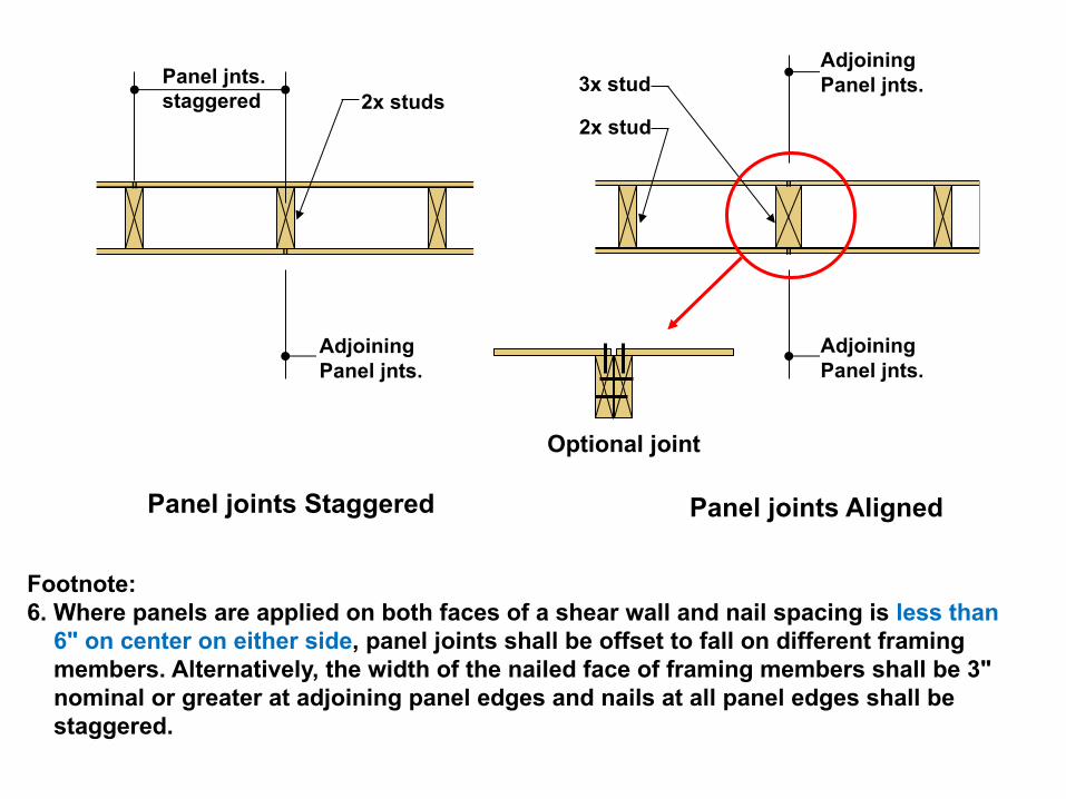
Footnote:6. Where panels are applied on both faces of a shear wall and nail spacing is less than
6" on center on either side, panel joints shall be offset to fall on different framing members. Alternatively, the width of the nailed face of framing members shall be 3" nominal or greater at adjoining panel edges and nails at all panel edges shall be staggered.
Panel jnts.staggered
Adjoining Panel jnts.
Adjoining Panel jnts.
Adjoining Panel jnts.
Panel joints Staggered Panel joints Aligned
3x stud
2x stud2x studs
Optional joint

Square plate washers preventcross grain bending-splitting of sill plate
Sill plate
Cross grain bending (tension perp. to grain stresses)
Wood structural panel 1/2” Max
4.3.6.4.3 Anchor Bolts: • Foundation anchor bolts shall have a steel plate washer under each nut. • Minimum size-0.229”x3”x3” in. • The hole in the plate washer - Diagonally slotted, width of up to 3/16” larger
than the bolt diameter, and a slot length not to exceed 1-3/4” is permitted ifstandard cut washer is provided between the nut and the plate.
• The plate washer shall extend to within 1/2" of the edge of the bottom plate on the side(s) with sheathing.
• Required where sheathing nominal unit shear capacity is greater than 400 plf for wind or seismic. (i.e. 200 plf ASD, 320 plf LRFD)
Square Plate Washers
Shear Wall Anchorage
Standard cut washer if slotted hole

Standard cut washers • Permitted to be used where anchor bolts are designed to resist shear only and
the following requirements are met: a) The shear wall is designed segmented wall with required uplift anchorage at
shear wall ends sized to resist overturning neglecting DL stabilizing moment.
b) Shear wall aspect ratio, h:b, does not exceed 2:1. c) The nominal unit shear capacity of the shear wall does not exceed 980 plf
for seismic or 1370 plf for wind.
Standard cut plate washers
Sill plate
Cross grain bending (tension perp. to grain stresses)
Wood structural panel
Cut Washers

Lunch

Information Overload
Deer in Headlight
Shear Wall Design
• Shear Wall Types
• Shear wall Anchorage
• SDPWS Code Requirements
• Complete Load Paths
• ASCE 7 Offset Shear Wall Requirements
• Offset Shear Walls
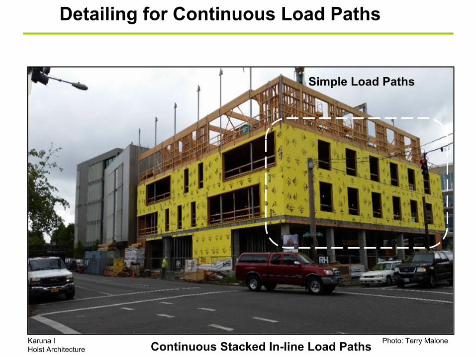
Detailing for Continuous Load Paths
Karuna IHolst Architecture
Photo: Terry MaloneContinuous Stacked In-line Load Paths
Simple Load Paths
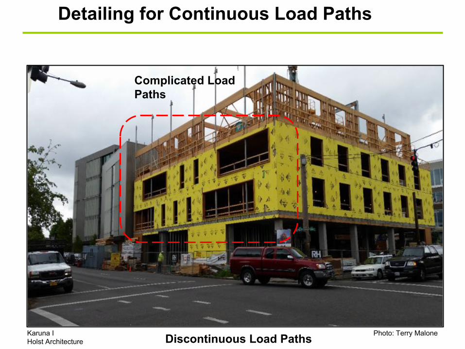
Detailing for Continuous Load Paths
Karuna IHolst Architecture
Photo: Terry MaloneDiscontinuous Load Paths
Complicated Load Paths

In-plane Offset Segmented Shear Walls
Hold Down(option 1)No irreg.
Wd
Hdr
Sill
Wd
Hold down(Typical)
Tie strap
Boundary nailing should be installed at each 2x stud at hold down and each plate
A
Compr. blocks required at all H.D. locations
Blk’g. or rim joist
Header/collector
Section C
Section B Section A
B C
Col
lect
or
C D
Alt. Config.
Sect. B
Anchor boltsor nails
Shear transfer Conn.
Tie strap
Nail shtg toeach 2x stud
Type 4 vert. irreg.SDC B-F
• Type 4 Vertical Irregularity, in-plane offset • ASCE 7-10 12.3.3.3 Elements supporting discontinuous walls SDC B-F• ASCE 7-10 12.3.3.4 25% increase in Fpx SDC D-F (connections)
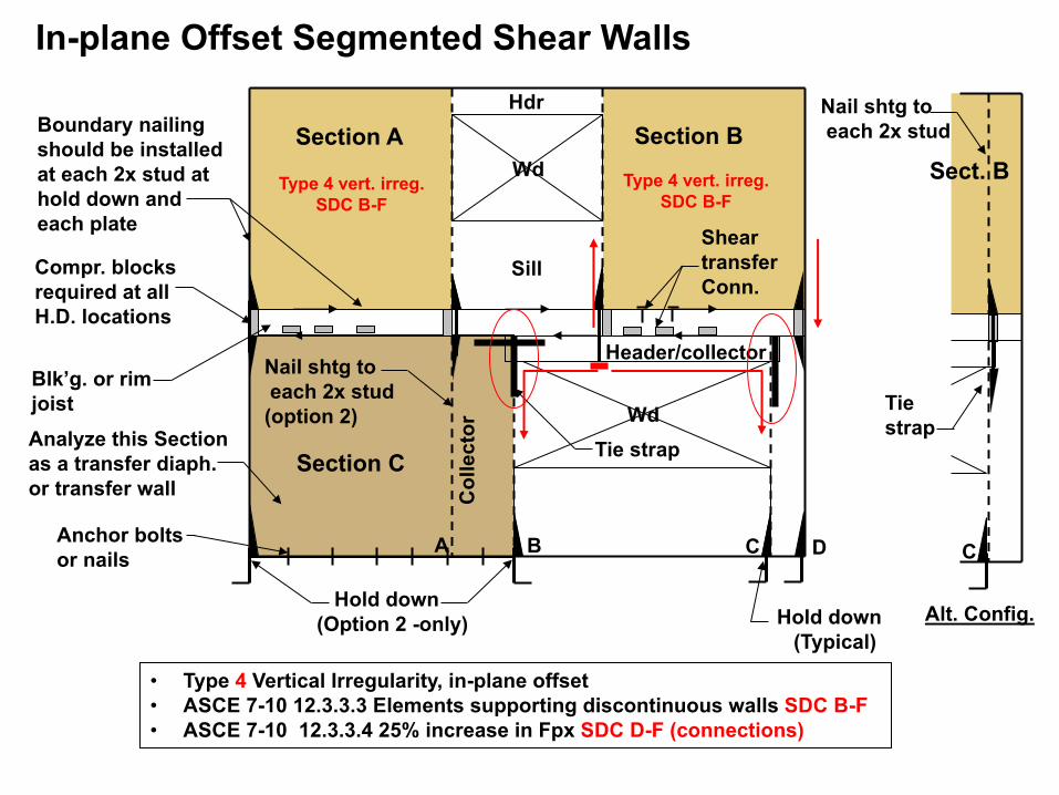
In-plane Offset Segmented Shear Walls
Wd
Hdr
Sill
Nail shtg toeach 2x stud
(option 2) Wd
Hold down(Typical)
Tie strap
Boundary nailing should be installed at each 2x stud at hold down and each plate
A
Compr. blocks required at all H.D. locations
Blk’g. or rim joistAnalyze this Section as a transfer diaph.or transfer wall
Header/collector
Section C
Section B Section A
B C
Col
lect
or
C D
Alt. Config.
Sect. B
Anchor boltsor nails
Shear transfer Conn.
Tie strap
Nail shtg toeach 2x stud
Type 4 vert. irreg.SDC B-F
Type 4 vert. irreg.SDC B-F
• Type 4 Vertical Irregularity, in-plane offset • ASCE 7-10 12.3.3.3 Elements supporting discontinuous walls SDC B-F• ASCE 7-10 12.3.3.4 25% increase in Fpx SDC D-F (connections)
Hold down(Option 2 -only)
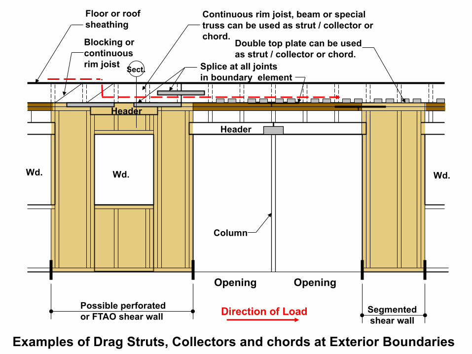
Wd. Wd. Wd.
Opening
Floor or roof sheathing
Blocking or continuous rim joist
Continuous rim joist, beam or special truss can be used as strut / collector or chord.
Double top plate can be used as strut / collector or chord.
Splice at all jointsin boundary element
Opening
Column
Possible perforated or FTAO shear wall
Segmentedshear wall
Header
Examples of Drag Struts, Collectors and chords at Exterior Boundaries
Sect.
Header
Direction of Load
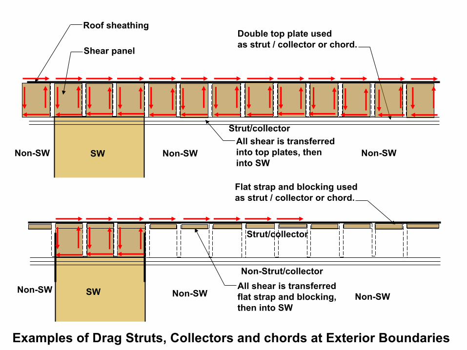
Roof sheathing
Shear panel
Double top plate used as strut / collector or chord.
Examples of Drag Struts, Collectors and chords at Exterior Boundaries
Flat strap and blocking used as strut / collector or chord.
All shear is transferred into top plates, then into SW
All shear is transferred flat strap and blocking, then into SW
SW
SW
Non-SWNon-SW
Non-SWNon-SW
Non-SW
Non-SW
Non-Strut/collector
Strut/collector
Strut/collector
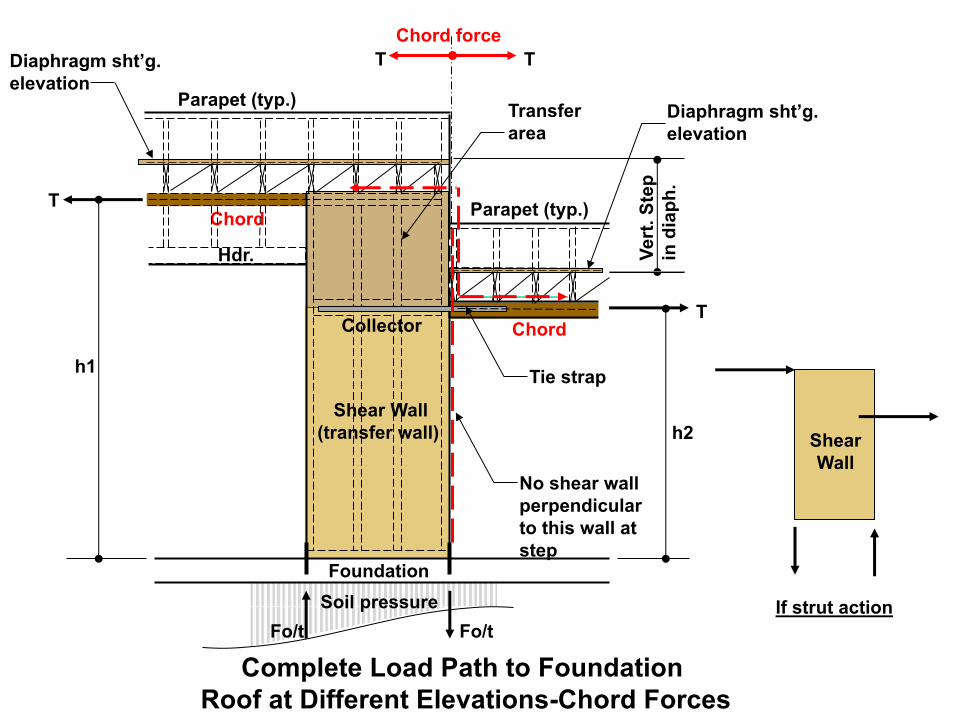
T
Shear Wall(transfer wall)
Hdr.
Collector Chord
Chord
h1
Diaphragm sht’g. elevation
Diaphragm sht’g. elevation
Parapet (typ.)
Vert
. Ste
pin
dia
ph.
Transfer area
Complete Load Path to Foundation Roof at Different Elevations-Chord Forces
Soil pressure
Chord force
Fo/tFo/t
Foundation
Parapet (typ.)
Tie strap
TT
If strut action
Shear Wall
T
h2
No shear wall perpendicular to this wall at step
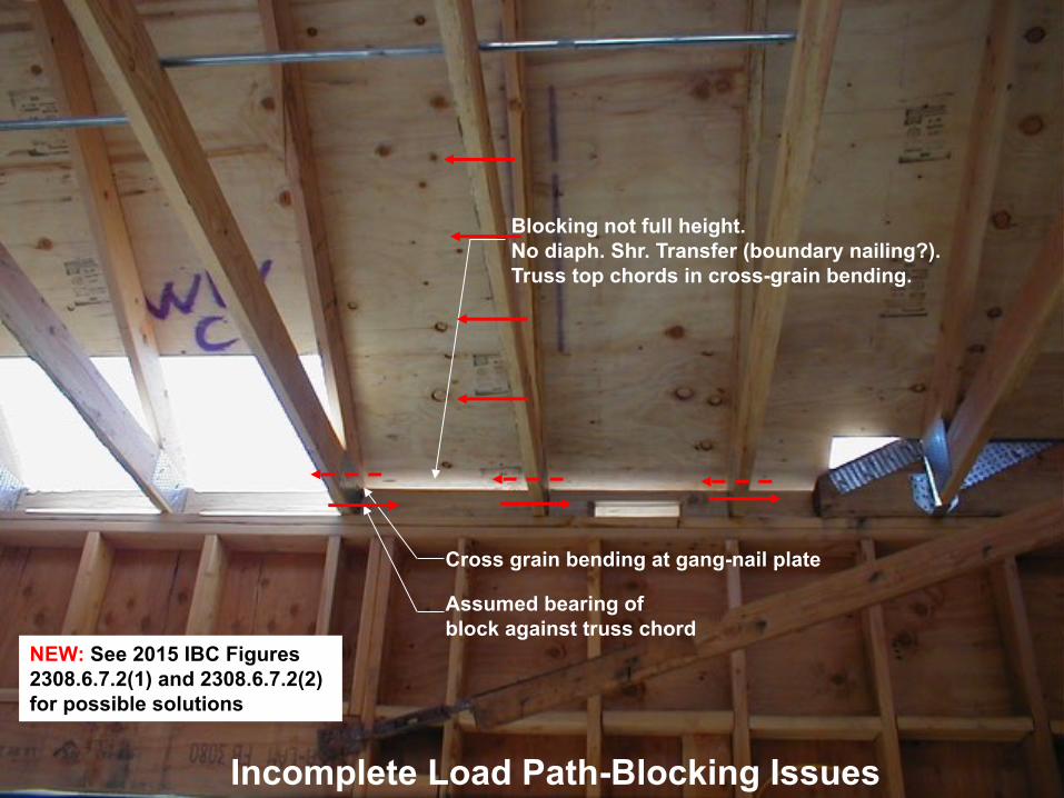
Blocking not full height.No diaph. Shr. Transfer (boundary nailing?).Truss top chords in cross-grain bending.
Cross grain bending at gang-nail plate
Assumed bearing of block against truss chord
Incomplete Load Path-Blocking Issues
NEW: See 2015 IBC Figures 2308.6.7.2(1) and 2308.6.7.2(2) for possible solutions

2015 IBC Figure 2308.6.7.2(1)
2015 IBC Figure 2308.6.7.2(2)
Insulation
Screened vent
Typical shear panel
Boundary nailing
Middle 3rd available for vent holes-No continuous vents
2x blocking
Venting OptionsA
A
2x vertical nailer
Truss
2x blocking
2x framing all 4 sides
Insulation
Insulation
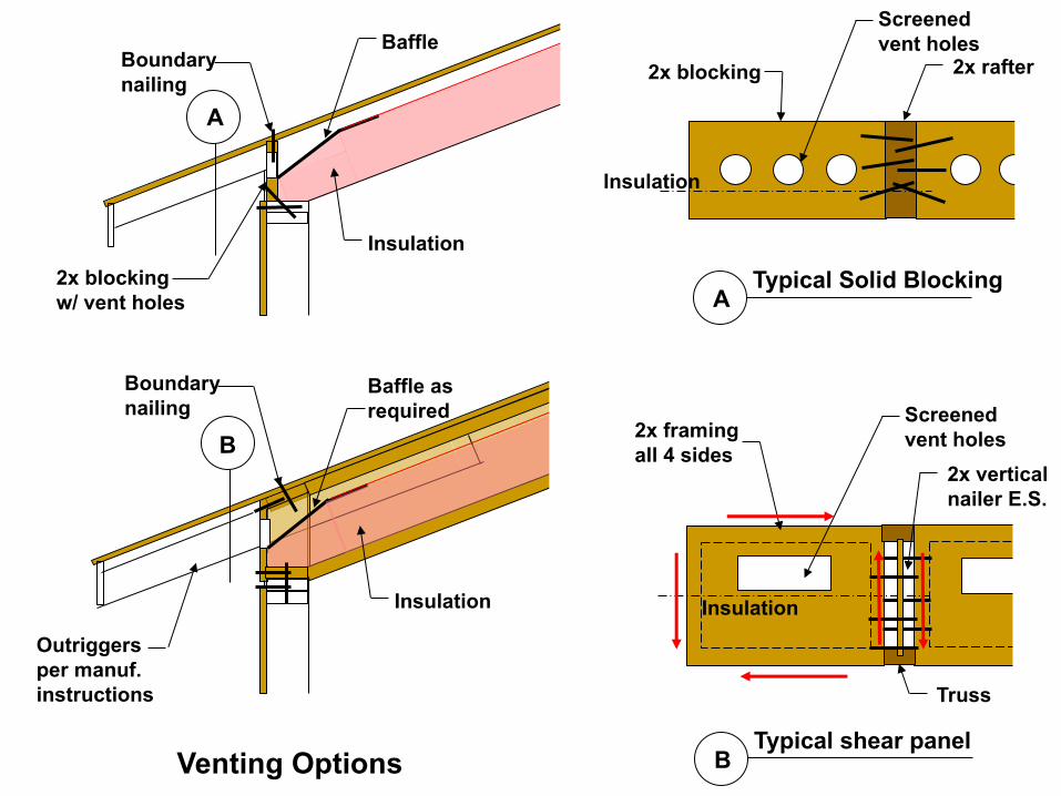
Insulation
Screened vent holes
Typical shear panel
2x framing all 4 sides
Boundary nailing
Outriggers per manuf. instructions
Baffle
2x blockingw/ vent holes
Venting Options B
B
Insulation
2x vertical nailer E.S.
Truss
Baffle asrequired
Insulation
Boundary nailing
Screened vent holes
Typical Solid Blocking
2x blocking
A
Insulation
2x rafter
A

Shear Wall Design
• Shear Wall Types
• Shear wall Anchorage
• SDPWS Code Requirements
• Complete Load Paths
• ASCE 7 Offset Shear Wall Requirements
• Offset Shear Walls
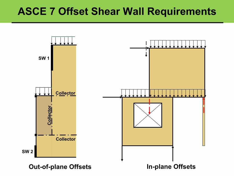
ASCE 7 Offset Shear Wall Requirements
SW 1
SW 2
Col
lect
or
Collector
Collector
Out-of-plane Offsets In-plane Offsets

Potential bucklingproblem w/ supporting columns and beams
F (Rho = structure)SDC D-F Diaphragm load at 2nd floor
SW1
SW3
SW4
SW5Collector / beam
Collector
Drag
strut
Drag
strut
Drag strut
Drag
strut
A
B3
2
1
A.75
A.33
The deflection equation must be adjusted to account for the uniformly distributed load plus the transfer force.
Elements requiring over-strength load combinations
Transfer diaphragm grid line 1 to 3 See Section 12.10.1.1(transfer forces)
ASCE 7 Table 12.3-2 Type 4 vertical irregularity: in-plane offset discontinuity
ASCE 7 Table 12.3-1 Type 4 horizontal irregularity: out-of-plane offset discontinuity in the LFRSload path
W (Fpx w/ Rho=1)
ASCE 7 Table 12.3-2 Type 4 vertical irregularity: in-plane offset discontinuity in the LFRS (if no H.D. at A.25)
Relevant Irregularities Per ASCE 7-10 Horizontal Irregularities Table 12.3-1 and Vertical Irregularities Table 12.3-2
SW2
H.D.
H.D.
A.25

Diaphragm
Shear wall is not
continuous to
foundation.
Type 4 horizontal
and vertical
irregularity
Chord
Co
lle
cto
r
Str
ut
Str
ut
Chord
Str
ut
Type 4 Horizontal & Vertical Offset Irregularity-SeismicS
W1
SW
2
SW
3
Type 4 horizontal irregularity-Out-of-plane offset irregularity occurs where there is a
discontinuity in lateral force resistance load path. Out-of-plane offset of at least one of
the vertical lateral force resisting elements.
Type 4 vertical irregularity-In-plane discontinuity in vertical lateral force resisting
element occurs where there is an offset of vertical seismic force resisting element
resulting in overturning demands on a beam, column, truss, wall or slab.
• ASCE 7-10 Section 12.3.3.3 (SDC B-F)
Elements supporting discontinuous walls or frames.
• ASCE 7-10 Section 12.3.3.4 (SDC D-F)
Increases in force due to irregularity1
2
B
3
C
A
Co
lle
cto
r S
W
SW
ab
ov
e
or
No
SW
SW
SW
SW
SW
SW
Co
lle
cto
r
Collector
1 2
Diaphragm
Str
ut Cantilever?

Type 4 Vertical Irregularity SDC D-F
SW3
Strut
. . .
. .
Blockingor shear panels
Continuous member
Also see 12.10.2.1 SDC C-F for collector requirements.
ASCE 7-10 Section 12.3.3.3 (SDC B-F)Elements supporting discont. Walls or frames:
Applies to:•Beams, columns, slabs, walls ortrusses.•Requires over-strength factor ofSection 12.4.3
2
. . .
. .

Diaphragm 1
Shear wall is not continuous to foundation.
Chord C
olle
ctor
Str
ut
Chord
Str
utType 4 Horizontal Irregularity-Seismic
SW
1S
W2
SW
3
ASCE 7-10 Section 12.3.3.4 (SDC D-F) -Type 4 Horizontal and Type 4 vertical irregularity requires a 25% increase in the diaphragm (inertial) design forces determined from 12.10.1.1 (Fpx) for the following elements:
• Connections of diaphragm to vertical elements and collectors.• Collectors and their connections to vertical elements.
1
2
B
3
C
A
Collectors and their connections to vertical (Grid lines 1, 2 and 3)
• Diaphragm shears are not required to be increased 25%.
• The transfer force (SW3) in SDC D-F must be increased by rho, per 12.10.1.1.
See 12.10.2 & 12.10.2.1 for collectors
Exception: Forces using the seismic load effects including the over-strength factor of Section 12.4.3 need not be increased.
Design diaphragm connections to SW and struts (Grid lines 1, 2 and 3)
SW
4S
W5

Type 2 Horiz., Type 3 Horiz., and Type 4 Vert. & Horiz. Irregularity SDC D-F(Interior collector similar)
SW
SW
Strut
ASCE 7-10 Section 12.3.3.4 (SDC D-F)• Type 2 Horizontal Re-entrant corner
Irregularity• Type 3 Diaphragm discontinuity
irregularity• Type 4 horizontal or vertical
irregularity:
Requires a 25% increase in the diaphragmdesign forces (Fpx) determined from 12.10.1.1for the following elements:
. . .
. .
Blockingor shear panels
Continuous member
Strut/collector
Alt. Collector/ strut Connection
• Connections of diaphragm to vertical elements and collectors.
3
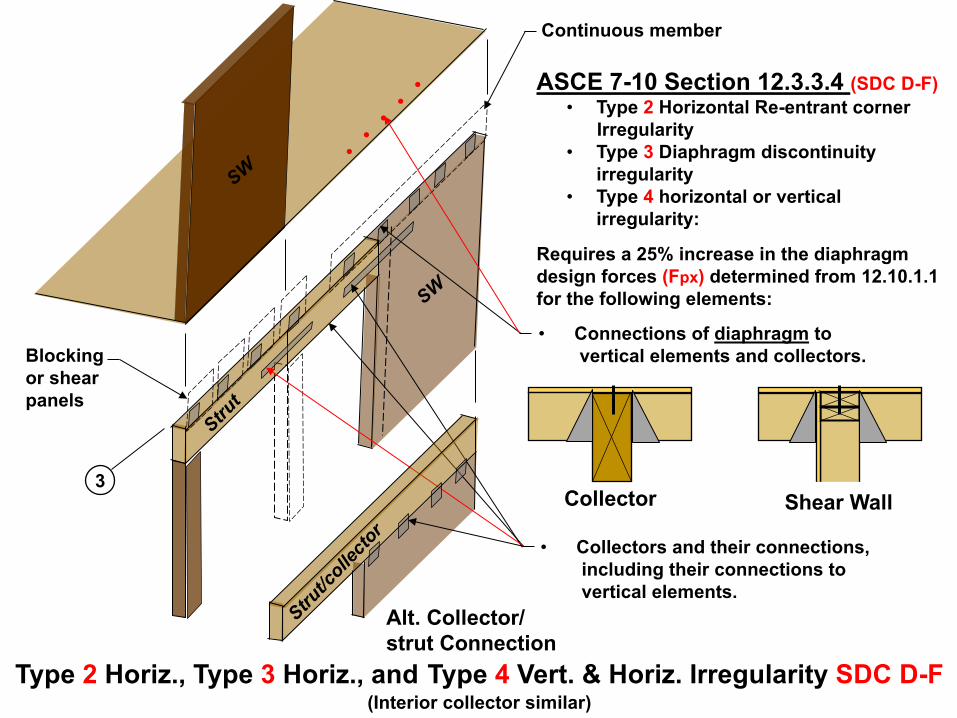
Type 2 Horiz., Type 3 Horiz., and Type 4 Vert. & Horiz. Irregularity SDC D-F(Interior collector similar)
SW
SW
Strut
ASCE 7-10 Section 12.3.3.4 (SDC D-F)• Type 2 Horizontal Re-entrant corner
Irregularity• Type 3 Diaphragm discontinuity
irregularity• Type 4 horizontal or vertical
irregularity:
Requires a 25% increase in the diaphragmdesign forces (Fpx) determined from 12.10.1.1for the following elements:
. . .
. .
Blockingor shear panels
Continuous member
Strut/collector
Alt. Collector/ strut Connection
• Connections of diaphragm to vertical elements and collectors.
Collector
• Collectors and their connections, including their connections to vertical elements.
Shear Wall3

Ftg.
Strut/Collector
Strut/Collector
SW1
Vr
V2
Dhr
Dh2
Ftg.
Supp
ort c
olum
n
A BA.25
SW2
Shear wall system at grid line 1In-plane Offset of Wall
Supp
ort c
olum
n
ASCE 7 Table 12.3-2-Type 4 vertical irregularity- In-plane offset discontinuity in the LFRS
Wall element is designed for standard load combinations of ASCE 7-10 Sections 2.3 or 2.4.
Shear wall anchorage is designed for standard load combinations of Sections 2.3 or 2.4.
Column elements are designed for standard load combinations 2.3 or 2.4.
Wall designed for over-strength per ASCE 7-10 Section 12.3.3.3 (SDC B-F) and/or 12.3.3.4 (SDC D-F)
Shear wall hold downs are designed for standard load combinations of Sections 2.3 or 2.4.
Col
lect
or
Assuming no hold down
See struts and collectors
Connectionsare designed for standard load combinations 2.3 or 2.4.

Ftg.
Support beam/collector
Collector
SW3
Vr
V2
Sup
port
col
umn
Ftg.
Sup
port
col
umn
A BA.33
Shear wall system at grid line 2Out-of-Plane Offset
Footings and connections are not required to be designed for over-strength.
Dhr
Dh2
Dv
ASCE 7 Table 12.3-1-Type 4 horizontal irregularity- out of-plane offset discontinuity in the LFRS
Wall element is designed for standard load combinations of ASCE 7-10 Sections 2.3 or2.4.
Shear wall hold downs and connections are designed for standard load combinations of ASCE 7-10 Sections 2.3 or 2.4.
Elements supporting discontinuous walls or frames require over-strength Factor of Section 12.4.3.
Collector and columns shall be designed in accordance with ASCE 7-10 section: 12.3.3.3
Connection is designed for standard load combinations of Sections 2.3 or 2.4.
See struts and collectors
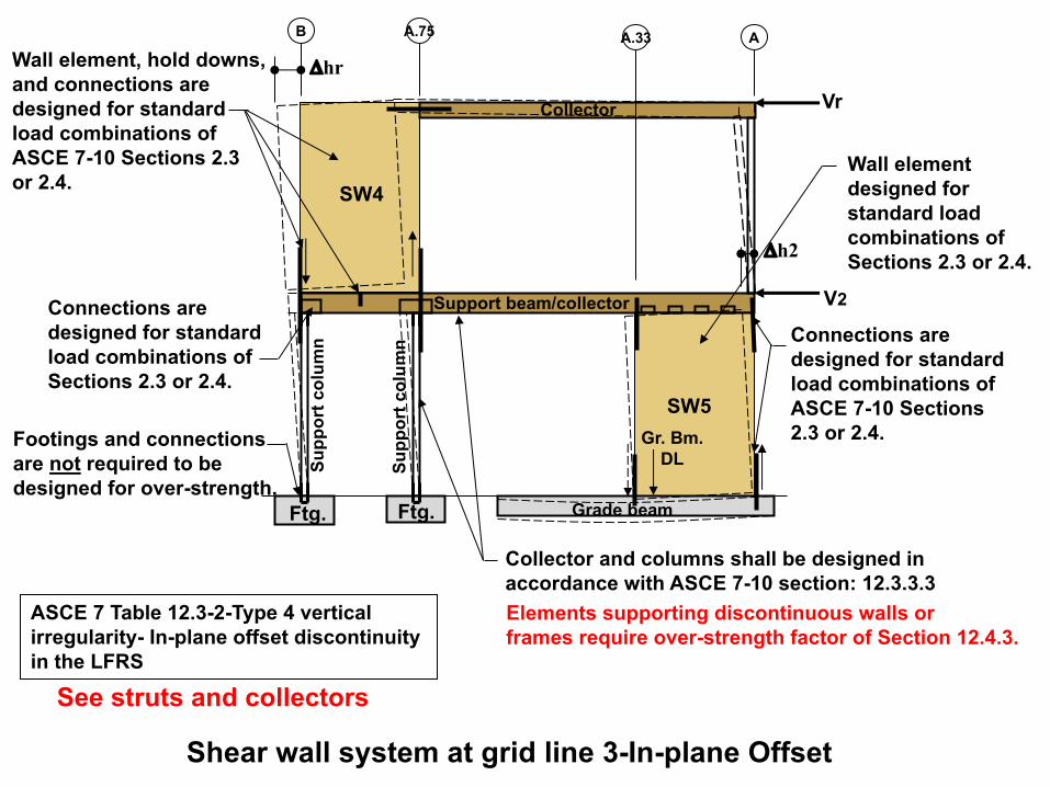
Grade beamFtg.
Support beam/collector
Collector
SW4
SW5
Vr
V2S
up
po
rt c
olu
mn
Gr. Bm.
DL
Ftg.
Su
pp
ort
co
lum
n
AB A.75
A.33
Shear wall system at grid line 3-In-plane Offset
ASCE 7 Table 12.3-2-Type 4 vertical
irregularity- In-plane offset discontinuity
in the LFRS
Wall element, hold downs,
and connections are
designed for standard
load combinations of
ASCE 7-10 Sections 2.3
or 2.4.
Elements supporting discontinuous walls or
frames require over-strength factor of Section 12.4.3.
Collector and columns shall be designed in
accordance with ASCE 7-10 section: 12.3.3.3
Connections are
designed for standard
load combinations of
Sections 2.3 or 2.4.
Dhr
Dh2
Connections are
designed for standard
load combinations of
ASCE 7-10 Sections
2.3 or 2.4.
Wall element
designed for
standard load
combinations of
Sections 2.3 or 2.4.
See struts and collectors
Footings and connections
are not required to be
designed for over-strength.

Concrete Podium slab
Support beam/collector
Collector
SW4
SW5
Vr
V2Su
ppor
t col
umn
Gr. Bm. DLSu
ppor
t col
umn
AB A.75 A.33
Discontinuous Shear wall system at Podium Slab
Wall element, hold downs, and connections are designed for standard load combinations of ASCE 7-10 Sections 2.3 or 2.4.
Connections are designed for standard load combinations of Sections 2.3 or 2.4.
Dhr
Dh2
Connections are designed for standard load combinations of ASCE 7-10 Sections 2.3 or 2.4.
Wall element designed for standard load combinations of Sections 2.3 or 2.4.
Collector, columns, Podium slabs and beam shall be designed using the over-strength factor of ASCE 7-10 section 12.3.3.3
Elements supporting discontinuous walls or frames require over-strength factor of Section 12.4.3.
Concrete beam
All connections to the members above slab are designed for standard load combinations of ASCE 7-10 Sections 2.3 or 2.4.
Conc. wall
Seismic reactions from the flexible upper portion shall be amplified by the ratio
!"#$$%& $'&()'*!"+',%& $'&()'*
> 1.0
for connections embedded into slab (does not apply to gravity reactions).
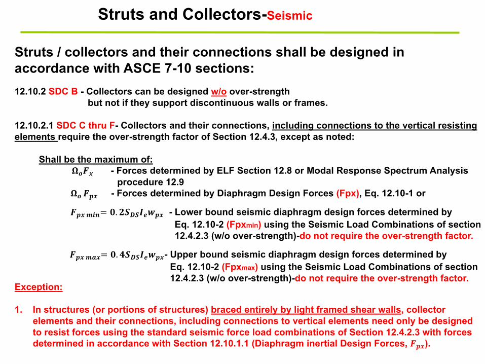
12.10.2 SDC B - Collectors can be designed w/o over-strengthbut not if they support discontinuous walls or frames.
12.10.2.1 SDC C thru F- Collectors and their connections, including connections to the vertical resisting elements require the over-strength factor of Section 12.4.3, except as noted:
Shall be the maximum of:!"#$ - Forces determined by ELF Section 12.8 or Modal Response Spectrum Analysis
procedure 12.9 !" #%$ - Forces determined by Diaphragm Design Forces (Fpx), Eq. 12.10-1 or
#%$&'(= *. ,-.-/01%$ - Lower bound seismic diaphragm design forces determined byEq. 12.10-2 (Fpxmin) using the Seismic Load Combinations of section12.4.2.3 (w/o over-strength)-do not require the over-strength factor.
Struts / collectors and their connections shall be designed in accordance with ASCE 7-10 sections:
Exception:
1. In structures (or portions of structures) braced entirely by light framed shear walls, collector elements and their connections, including connections to vertical elements need only be designed to resist forces using the standard seismic force load combinations of Section 12.4.2.3 with forces determined in accordance with Section 12.10.1.1 (Diaphragm inertial Design Forces, #%$).
Struts and Collectors-Seismic
#%$&2$= *. 3-.-/01%$- Upper bound seismic diaphragm design forces determined byEq. 12.10-2 (Fpxmax) using the Seismic Load Combinations of section12.4.2.3 (w/o over-strength)-do not require the over-strength factor.

Shear Wall Design
• Shear Wall Types
• Shear wall Anchorage
• SDPWS Code Requirements
• Complete Load Paths
• ASCE 7 Offset Shear Wall Requirements
• Offset Shear Walls
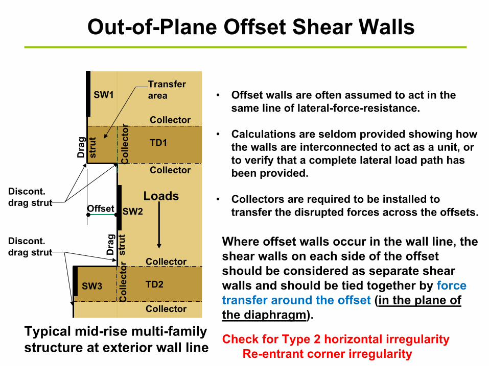
Out-of-Plane Offset Shear Walls
Loads
Col
lect
or
Collector
Collector
TD1
SW1
SW2
Transfer area
Offset
Discont.drag strut
Dra
g st
rut
Dra
g st
rut
SW3
Col
lect
or
Collector
Collector
TD2
• Offset walls are often assumed to act in the same line of lateral-force-resistance.
• Calculations are seldom provided showing how the walls are interconnected to act as a unit, or to verify that a complete lateral load path has been provided.
• Collectors are required to be installed to transfer the disrupted forces across the offsets.
Discont.drag strut
Typical mid-rise multi-family structure at exterior wall line
Where offset walls occur in the wall line, the shear walls on each side of the offset should be considered as separate shear walls and should be tied together by force transfer around the offset (in the plane of the diaphragm).
Check for Type 2 horizontal irregularityRe-entrant corner irregularity

SW 1
SW 2
25’ 20’
15’
200
plf
Drag strut
Ch
ord
co
llect
ors
Ch
ord
80’
35’
50’
Drag strut is discontinuous
1 2
A
B
3
C
4
10’25’ 5’
15’
200
plf
TD1C
ho
rd
colle
cto
rs
Pos. direction + -
SW 3 SW 4
8’
8’
Drag strut
Collector
5’
12’45’
80’
Drag strut
Drag strutC
ho
rd
Drag strut
Diaphragm with Horizontal End OffsetLongitudinal Loading-Out-of-plane offset Shear Walls
Offset SW
Offset SW
Support
Support
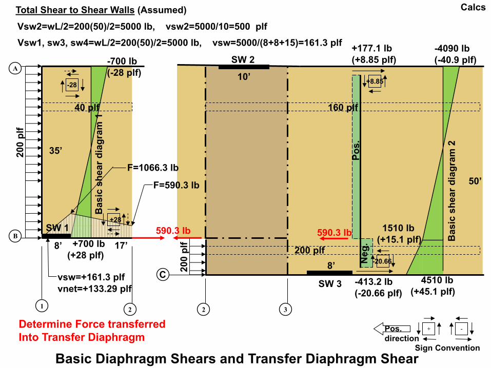
SW 2
35’
50’
1 2
A
B
3
C
10’
8’
Pos. direction
+8.85
+ -
Ba
sic
sh
ea
r d
iag
ram
2
8’
2
SW 3
Po
s.
40 plf 160 plf
20
0 p
lf
20
0 p
lf
SW 1
Ba
sic
sh
ea
r d
iag
ram
1
vsw=+161.3 plfvnet=+133.29 plf
F=1066.3 lb
F=590.3 lb
590.3 lb590.3 lb
-700 lb(-28 plf)
+700 lb (+28 plf)
+177.1 lb(+8.85 plf)
4510 lb(+45.1 plf)
1510 lb(+15.1 plf)
-4090 lb (-40.9 plf)
Basic Diaphragm Shears and Transfer Diaphragm Shear
-20.66 Ne
g.
-413.2 lb(-20.66 plf)
+28
200 plf
-28
Vsw2=wL/2=200(50)/2=5000 lb, vsw2=5000/10=500 plf
Vsw1, sw3, sw4=wL/2=200(50)/2=5000 lb, vsw=5000/(8+8+15)=161.3 plf
Determine Force transferred Into Transfer Diaphragm
Total Shear to Shear Walls (Assumed)
17’
Calcs
Sign Convention
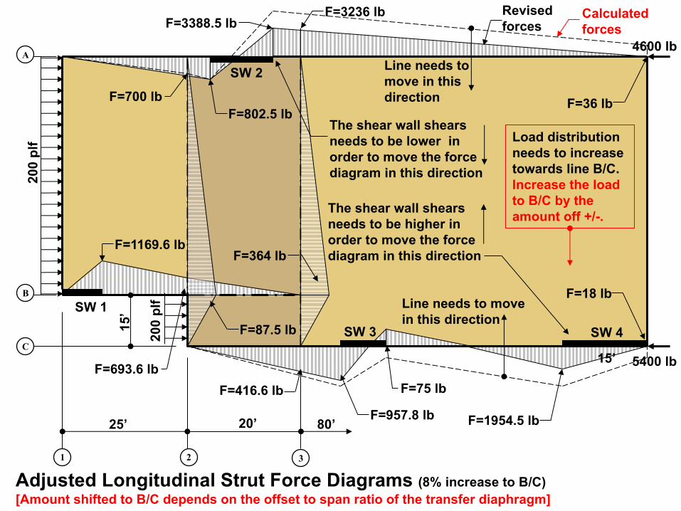
4600 lb
25’ 20’
15’
80’
1 2
A
B
3
C
Adjusted Longitudinal Strut Force Diagrams (8% increase to B/C)[Amount shifted to B/C depends on the offset to span ratio of the transfer diaphragm]
SW 1
SW 3 SW 4
SW 2
15’ 5400 lb
F=1954.5 lb
F=75 lb
F=957.8 lb
F=416.6 lb
F=802.5 lb
F=693.6 lb
F=1169.6 lb
F=700 lb F=36 lb
F=18 lb
F=364 lb
F=87.5 lb
F=3388.5 lbF=3236 lb
Line needs to move in this direction
The shear wall shearsneeds to be higher in order to move the force diagram in this direction
Line needs to move in this direction
The shear wall shearsneeds to be lower in order to move the force diagram in this direction
Load distribution needs to increase towards line B/C. Increase the load to B/C by the amount off +/-.
Calculated forces
Revisedforces
200
plf
200
plf
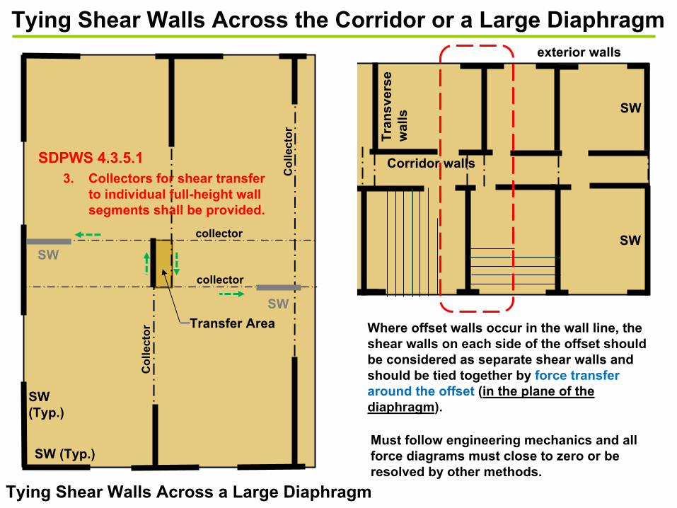
SW
SW
(Typ.)
SW
SW (Typ.)
Tra
ns
ve
rs
e
wa
lls
exterior walls
Corridor walls
Transfer Area
collector
Co
llecto
r
collector
Co
llecto
r
Tying Shear Walls Across the Corridor or a Large Diaphragm
Tying Shear Walls Across a Large Diaphragm
SW
SW
3. Collectors for shear transfer
to individual full-height wall
segments shall be provided.
SDPWS 4.3.5.1
Where offset walls occur in the wall line, the
shear walls on each side of the offset should
be considered as separate shear walls and
should be tied together by force transfer
around the offset (in the plane of the
diaphragm).
Must follow engineering mechanics and all
force diagrams must close to zero or be
resolved by other methods.

Diaphragm 1 Diaphragm 2
SW
1S
W2
1 2
B
3
C
A
D
W=200 plf
78’ 122’
6’
22’
22’
50’
7800 # Sum=20000 # 12200 #
156
156 244
244
RL=RR=200(78/2)=7800 #vR=7800/50=156 plf
RL=RR=200(122/2)=12200 #vR=12200/50=244 plf
Sum=40000 #=200 plf(200’)
vSW=454.55 plfvNet=54.55 plf
1200
1200
Layout 1-Full length walls aligned

Diaphragm 1 Diaphragm 2
SW
1
SW
2
SW3
1 2
B
3
C
A
D
4
SW4
112
plf
88 p
lf
88 p
lf11
2 p
lf
24 p
lf
W=200 plf
78’ 122’
82’
4’
118’
6’
22’
22’
50’
Sum=7976 # Sum=20048 # Sum=11976 #
156
156
164 236
236
244
244
164
8 8
RL=RR=112(78/2)=4368 #vR=4368/28=156 plf
4368 #
RL=RR=88(82/2)=3608 #vR=3608/22=164 plf
RL=RR=88(122/2)=5368 #vR=5368/28=244 plf
RL=RR=112(118/2)=6608 #vR=6608/28=236 plf
3608 #
Transfer AreaRL=RR=24(4/2)=48 #vL=vR=48/6=8 plf
Sum=40000 #=200 plf(200’)
5368 #
6608 #
Layout 2-Full length offset walls
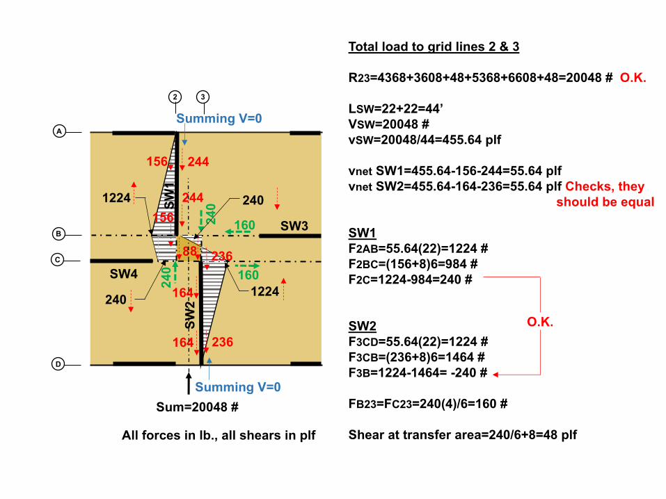
SW
1
SW
2
SW3
2
B
3
C
A
D
SW4
156
156
164 236
244
244
164
8
160
16024
0
24
0
Total load to grid lines 2 & 3
R23=4368+3608+48+5368+6608+48=20048 # O.K.
LSW=22+22=44’
VSW=20048 #
vSW=20048/44=455.64 plf
vnet SW1=455.64-156-244=55.64 plf
vnet SW2=455.64-164-236=55.64 plf Checks, they
should be equal
SW1
F2AB=55.64(22)=1224 #
F2BC=(156+8)6=984 #
F2C=1224-984=240 #
SW2
F3CD=55.64(22)=1224 #
F3CB=(236+8)6=1464 #
F3B=1224-1464= -240 #
FB23=FC23=240(4)/6=160 #
Shear at transfer area=240/6+8=48 plf
Sum=20048 #
1224
1224240
240
8 236
Summing V=0
Summing V=0
All forces in lb., all shears in plf
O.K.
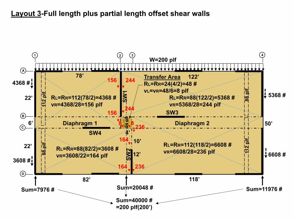
Diaphragm 1 Diaphragm 2S
W1
SW
2
SW3
1 2
B
3
C
A
D
4
SW4
112
plf
88 p
lf
88 p
lf11
2 p
lf
24 p
lf
W=200 plf
78’ 122’
82’
4’
118’
6’
22’
22’
50’
Sum=7976 # Sum=20048 # Sum=11976 #
156
156
164 236
236
244
244
164
8 8
RL=RR=112(78/2)=4368 #vR=4368/28=156 plf
4368 #
RL=RR=88(82/2)=3608 #vR=3608/22=164 plf
RL=RR=88(122/2)=5368 #vR=5368/28=244 plf
RL=RR=112(118/2)=6608 #vR=6608/28=236 plf
3608 #
Transfer AreaRL=RR=24(4/2)=48 #vL=vR=48/6=8 plf
Sum=40000 #=200 plf(200’)
5368 #
6608 #
Layout 3-Full length plus partial length offset shear walls
10’
12’
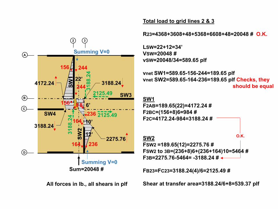
SW
1
SW
2
SW3
2
B
3
C
A
D
SW4
156
156
164 236
244
244
164
8
2125.49
2125.4931
88.2
4
3188
.24
Total load to grid lines 2 & 3
R23=4368+3608+48+5368+6608+48=20048 # O.K.
LSW=22+12=34’VSW=20048 #vSW=20048/34=589.65 plf
vnet SW1=589.65-156-244=189.65 plfvnet SW2=589.65-164-236=189.65 plf Checks, they
should be equal
SW1F2AB=189.65(22)=4172.24 #F2BC=(156+8)6=984 #F2C=4172.24-984=3188.24 #
SW2FSW2 =189.65(12)=2275.76 #FSW2 to 3B=(236+8)6+(236+164)10=5464 #F3B=2275.76-5464= -3188.24 #
FB23=FC23=3188.24(4)/6=2125.49 #
Shear at transfer area=3188.24/6+8=539.37 plf
Sum=20048 #
4172.24
2275.76
3188.24
3188.24
8
236
Summing V=0
Summing V=0
All forces in lb., all shears in plf
O.K.
22’
10’
12’
6’

Diaphragm 1 Diaphragm 2S
W2
SW3
1 2
B
3
C
A
D
4
SW4
112
plf
88 p
lf
88 p
lf11
2 p
lf
24 p
lf
W=200 plf
78’ 122’
82’
4’
118’
6’
22’
22’
50’
Sum=7976 # Sum=20048 # Sum=11976 #
156
156
164 236
236
244
244
164
8 8
RL=RR=112(78/2)=4368 #vR=4368/28=156 plf
4368 #
RL=RR=88(82/2)=3608 #vR=3608/22=164 plf
RL=RR=88(122/2)=5368 #vR=5368/28=244 plf
RL=RR=112(118/2)=6608 #vR=6608/28=236 plf
3608 #
Transfer AreaRL=RR=24(4/2)=48 #vL=vR=48/6=8 plf
Sum=40000 #=200 plf(200’)
5368 #
6608 #
Layout 4 - Partial length offset shear walls
10’
12’
SW
110
’
12’
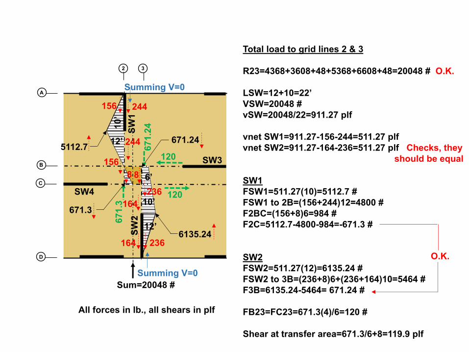
Total load to grid lines 2 & 3
R23=4368+3608+48+5368+6608+48=20048 # O.K.
LSW=12+10=22’VSW=20048 #vSW=20048/22=911.27 plf
vnet SW1=911.27-156-244=511.27 plfvnet SW2=911.27-164-236=511.27 plf Checks, they
should be equal
SW1FSW1=511.27(10)=5112.7 #FSW1 to 2B=(156+244)12=4800 #F2BC=(156+8)6=984 #F2C=5112.7-4800-984=-671.3 #
SW2FSW2=511.27(12)=6135.24 #FSW2 to 3B=(236+8)6+(236+164)10=5464 #F3B=6135.24-5464= 671.24 #
FB23=FC23=671.3(4)/6=120 #
Shear at transfer area=671.3/6+8=119.9 plf
SW
2
SW3
2
B
3
C
A
D
SW4
156
156
164 236
244
244
164
8
Sum=20048 #
671.24
8
236
Summing V=0
Summing V=0
All forces in lb., all shears in plf
O.K.
10’
12’
6’
120
12067
1.24
671.
3
5112.7
6135.24
12’S
W1
10’
671.3

120 Union, San Diego, CATogawa Smith Martin
Carbon 12, Portland, ORPATH Architecture
DraftR. Terry Malone, P.E., S.E., Senior Technical Director
•Overview•Relevant ASCE 7-16 and 2015 SDPWS Code Requirements
1.Diaphragm Flexibility-Seismic2.Open Front Diaphragms3.Torsional Irregularities4.Redundancy5.Diaphragm Design Forces
•Basic Information•Lateral Load Calculations
1.Calculate Seismic Forces2.Rigid Diaphragm Analysis3.Shear Wall Deflections
Seismic Design Example of a Cantilever Wood Diaphragm
Scott Breneman, PHD, PE, SE, Senior Technical Director

Reference Materials
http://www.woodworks.org/wp-content/uploads/Irregular-Diaphragms_Paper1.pdf
• The Analysis of Irregular Shaped Structures: Diaphragms and Shear Walls-Malone, Rice-Book published by McGraw-Hill, ICC
• Woodworks Presentation Slide Archives-Workshop-Advanced Diaphragm Analysis
• NEHRP (NIST) Seismic Design Technical Brief No. 10-Seismic Design of Wood Light-Frame Structural Diaphragm Systems: A Guide for Practicing Engineers
• SEAOC Seismic Design Manual, Volume 2
• Woodworks-The Analysis of Irregular Shaped Diaphragms (paper). Complete Example with narrative and calculations.
• Webinar Archive- Offset Diaphragms -Part 1• Webinar Archive- Offset Shear Walls-Part 2• Slide Archive-Workshop-Advanced Diaphragm Analysis • Slide Archive-Offset Diaphragms and Shear Walls
• Webinar Archive- Lateral Design Considerations for Mid-rise Structures-Stacked multi-story shear walls (MBA)
Information on Website

Method of Analysis and Webinar References
Diaphragms OpeningsOffset Shear WallsOffset Diaphragms
Mid-rise Design Considerations
Presentation Slide Archives, Workshops, White papers, research reportsInformation on Website

Questions?This concludes Our Workshop Presentation on Advanced Diaphragm Analysis
R. Terry Malone, P.E., S.E.Senior Technical DirectorWoodWorks.org
Contact Information:[email protected]


![Ultrasound shear wave elastography for assessing diaphragm ......ultrasound (US) as it provides direct visualization of muscle structure and functioning [15]. Diaphragm US is an interesting](https://static.fdocuments.in/doc/165x107/611e5e1c752520518346b7c6/ultrasound-shear-wave-elastography-for-assessing-diaphragm-ultrasound-us.jpg)
