Diamond Transmission Partners Hornsea One Ltd ...
42
Diamond Transmission Partners Hornsea One Limited Decommissioning Plan December 2020 Page 1 of 42 Diamond Transmission Partners Hornsea One Ltd Decommissioning Programme
Transcript of Diamond Transmission Partners Hornsea One Ltd ...
Diamond Transmission Partners Hornsea One Limited Decommissioning Plan December 2020
Page 1 of 42
Diamond Transmission Partners
Hornsea One Ltd
Decommissioning Programme
Diamond Transmission Partners Hornsea One Limited Decommissioning Plan December 2020
Page 2 of 42
Document History
Issue Date Summary of Changes /
Reasons Author(s)
Approved By
(Inc. Job
Title)
1 23/04/20 First issue. J Matthews G Thornton
2 29/09/20 Updated in line with BEIS
comments dated 10/08/20.
J Matthews G Thornton
3 17/12/20 Sections 7, 8, 10 and 14
updated following comments
from Frazer Nash.
J Matthews G Thornton
TABLE OF CONTENTS
Contents
TABLE OF CONTENTS ............................................................................................................................ 2
1 INTRODUCTION ........................................................................................................................... 3
2 EXECUTIVE SUMMARY ............................................................................................................... 5
3 BACKGROUND INFORMATION............................................................................................... 6
4 DESCRIPTION OF ITEMS TO BE DECOMMISSIONED ................................................ 22
5 DESCRIPTION OF ITEMS TO BE DECOMMISSIONED ................................................ 23
6 DESCRIPTION OF PROPOSED DECOMMISSIONING MEASURES ......................... 26
7 ENVIRONMENTAL IMPACT ASSESSMENT....................................................................... 36
8 CONSULTATION WITH KEY STAKEHOLDERS AND GENERAL PUBLIC .............. 38
9 COSTS AND FINANCIAL SECURITY ................................................................................... 39
10 PROPOSED DECOMMISSIONING SCHEDULE ................................................................ 39
11 PROJECT MANAGEMENT AND VERIFICATION ............................................................. 40
12 SEA-BED CLEARANCE .............................................................................................................. 41
13 RESTORATION OF THE SITE ................................................................................................. 41
14 POST-DECOMMISSIONING MONITORING, MAINTENANCE AND
MANAGEMENT OF THE SITE ................................................................................................. 42
15 SUPPORTING STUDIES ........................................................................................................... 42
Diamond Transmission Partners Hornsea One Limited Decommissioning Plan December 2020
Page 3 of 42
1 Introduction
This document presents the proposed OFTO Decommissioning Programme for the
Diamond Transmission Partners Hornsea One Limited (“DTPH”) assets and is
based upon the Decommissioning Programme1 proposed by Orsted Wind Power
A/S Limited (the “Developer”). The Decommissioning Programme proposed by
DTPH is informed and supported by the Environmental Impact Assessment
(“EIA”).
The project is a 1200MW wind farm developed by the Developer.
The Hornsea Offshore Wind Farm Project One (“HOW01”) has been awarded a
number of primary consents necessary for its construction and operation. Those
consents with provisions relating to decommissioning of the offshore wind farm
are shown in Table 1.1.
Table 1.1: Hornsea Offshore Wind Farm Project One Consents
Regulation Legislative
Context
Achieved Consents Authority
Secretary of
State for the
Department
for Business,
Energy and
Industrial
Strategy
(“BEIS”) /
Planning
Inspectorate
(“PINS”)
Section 36
consent granted
10/12/2014
Permission to operate onshore
and offshore generating
stations with a generating
capacity above 50MW
Secretary of
State for
BEIS/ PINS
Secretary of
State for BEIS
/ PINS
Development
Consent Order
(“DCO”)
Consent
granted
10/12/2014
DCO grants overall consent
for the entire scheme,
containing the maximum and
minimum design parameters
that the project must comply
with.
Secretary of
State for
BEIS/ PINS
Secretary of
State for BEIS
/ PINS
DCO
(Correction)
Consent
granted
30/04/2015
DCO grants overall consent
for the entire scheme,
containing the maximum and
minimum design parameters
that the project must comply
with.
Secretary of
State for
BEIS/ PINS
Secretary of
State for BEIS
/ PINS
DCO
(Amendment)
Consent
granted
31/03/2016
DCO grants overall consent
for the entire scheme,
containing the maximum and
minimum design parameters
that the project must comply
with.
Secretary of
State for
BEIS/ PINS
Secretary of
State for BEIS
/ PINS
DCO
(Amendment)
Consent
granted
23/03/2017
DCO grants overall consent
for the entire scheme,
containing the maximum and
minimum design parameters
that the project must comply
with.
Secretary of
State for
BEIS/ PINS
1 2.7.2.3.10 HOW01 Decommissioning Programme VE (00064353_A)
Diamond Transmission Partners Hornsea One Limited Decommissioning Plan December 2020
Page 4 of 42
Regulation Legislative
Context
Achieved Consents Authority
Marine
Management
Organisation
Marine and
Coastal Access
Act 2009: Part
4 – Marine
Licensing
Issued
10/12/14
Deemed marine licence
granted as part of the DCO.
Marine
Management
Organisation
In accordance with Section 105(02) of the Energy Act 2004, the Developer was
required to prepare a draft Decommissioning Programme for the HOW01 and to
submit the document to DECC (now Department for Business & Industrial
Strategy (“BEIS”)) for approval prior to the construction of the wind farm.
The Developer’s Decommissioning Programme was submitted to BEIS and was
approved on 07 March 2018. The Developer in their financial security document
state that the OFTO assets will be decommissioned by the appointed OFTO. This
will remove any obligations they have under the licence which pass to the OFTO.
If possible the generator assets will be decommissioned at the same time as the
DTPH assets after the expected operational life time of 25 years. At the end of its
lifetime, the transmission assets will be decommissioned in order to restore the
site as far back to its original conditions as possible.
The Decommissioning Programme will be continuously reviewed and revised
throughout the life of the project. These reviews will take into account any
changes in legislation, circumstances, technological advancements and regulatory
requirements.
DTPH will adopt the principles of the BEIS programme process stages and will
follow the process as set out below.
Table 1.2: BEIS Programme Process Stages
Stage Description
Stage 1 Preliminary discussion between BEIS and the Developer
Stage 2 Issue of Section 105 Notice by Secretary of State requiring a
decommissioning programme be submitted within a specified timescale
Stage 3 Detailed discussions; submission and consideration of a draft
programme (including proposed financial security measures)
Stage 4 Consultation with interested parties
Stage 5 Formal submission of a decommissioning programme and approval
under section 106 of the Act
Stage 6 In operation updates:
Reviews and modifications of the approved decommissioning
programme (and any financial security) leading up to Secretary of
State accepting/requiring any relevant modifications to the final pre-
decommissioning version; and
Changes in timeline or ownership
Stage 7 Execution of the final version of the approved decommissioning
programme
Stage 8 Submission of successful post-decommissioning repot and conclusion of
the Energy Act Process
Diamond Transmission Partners Hornsea One Limited Decommissioning Plan December 2020
Page 5 of 42
2 Executive Summary
The Developer obtained consents and licences necessary for the construction of
the wind farm in 2014. The operational lifetime is approximately 25 years. At
the end of this time the objective will be to decommission the asset in accordance
with the provisions set out in the various licences obtained.
In accordance with section 105(2) of the Energy Act 2004, the Developer
submitted its Decommissioning Programme for HOW01 to BEIS and was approved
on 07 March 2018.
The proposed decommissioning measures set out in this Decommissioning
Programme aim to adhere to the existing UK and international legislation and
guidance notes. In addition, decommissioning industry best practice will be
applied, taking into account the legislation applying at the time of
decommissioning of the DTPH assets. DTPH will pay full regard to the “waste
hierarchy”, which suggests that reuse should be considered first, followed by
recycling, incineration with energy recovery and, lastly, disposal.
It is difficult to determine the decommissioning schedule, as unforeseen issues
can arise during the installation and operation of the assets, which ultimately
could affect the decommissioning. At the time of writing, no offshore wind farms
(including offshore transmission assets) worldwide have been decommissioned2,
so direct experience of the potential challenges are limited. Once other projects
start to be decommissioned, it will provide valuable insight into the timing, costs
and operational challenges to be faced.
The proposed decommissioning measures (in line with the Developers approved
decommissioning plan) for the offshore components of the DTPH assets can be
summarised as:
Complete removal of the offshore substation;
Offshore substation foundations cut off below seabed and removed;
Offshore export cable within the jurisdiction of Associated British Ports
(“ABP”) to be removed;
All other offshore export and interlink cables cut, weighted down and left in
situ; and
Sections of the export and interlink cables which are not buried and will not
remain buried post decommissioning will be cut and lifted off the seabed for
recycling.
In accordance with the Polluter Pays Principle, DTPH in conjunction with the
Developer proposes to clear the seabed in accordance with the provisions made in
this Decommissioning Programme and in the Marine and Coastal Access Act 2009
(Marine Licence), and to collect and provide evidence to reflect this.
DTPH in conjunction with the Developer is committed to restoring the site and
cable corridors to the condition it was in prior to construction, as far as it is
reasonably practicable. The key restoration work will relate to ensuring that all
cut foundations are made safe and adequately covered, and ensuring that cable
ends is adequately buried.
DTPH in conjunction with the Developer proposes that, following post
decommissioning, a full geophysical survey (swath, side scan sonar and
magnetometer) is carried out. The survey will be carried out by an independent 2 2 Danish windfarm Vindeby (1.8km from shore 4.95MW) decommissioned in 2017.
Swedish windfarm Yttre Stengrund (2km from shore, 10MW) decommissioned in 2016.
Both projects are small scale and do not include transmission assets. Though they
provide valuable insights, these can’t be used to benchmark for large offshore
transmission systems.
Diamond Transmission Partners Hornsea One Limited Decommissioning Plan December 2020
Page 6 of 42
survey contractor and all results issued to BEIS for review and comment and
provided to The Crown Estate. The area covered by the magnetometer and
geophysical surveys will be determined prior to decommissioning, but we are
aware of oil and gas installation guidance which specifies a 500 metres radius
around any installation.
A cost estimate for the plan has been derived, based on the equipment, personnel
requirements and the duration of works. Financial security provisions have been
carefully considered to ensure that this liability will be met.
In advance of decommissioning, the EIA will be reviewed to assess the potential
impacts that may arise and to identify any additional impacts that were not
covered in the initial EIA process and subsequent reviews.
Once the assets are nearing the end of their agreed operational life, DTPH will
initiate a final review of this document and the proposed programme of works.
Once this review is complete, a “Decommissioning Programme of Works” will be
developed, in conjunction with the Developer, and the schedule of works will be
determined in agreement with the statutory authorities.
3 Background Information
This section describes the project and gives a brief overview of the biological,
physical and human environment in the area.
3.1 Location
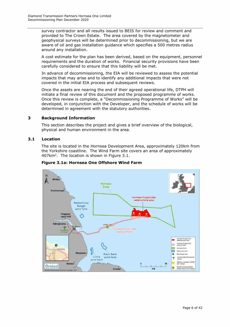
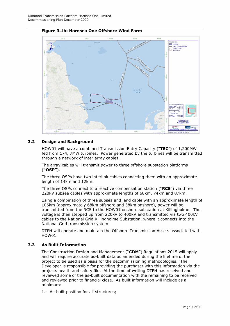
The site is located in the Hornsea Development Area, approximately 120km from
the Yorkshire coastline. The Wind Farm site covers an area of approximately
407km2. The location is shown in Figure 3.1.
Figure 3.1a: Hornsea One Offshore Wind Farm
Diamond Transmission Partners Hornsea One Limited Decommissioning Plan December 2020
Page 7 of 42
Figure 3.1b: Hornsea One Offshore Wind Farm
3.2 Design and Background
HOW01 will have a combined Transmission Entry Capacity (“TEC”) of 1,200MW
fed from 174, 7MW turbines. Power generated by the turbines will be transmitted
through a network of inter array cables.
The array cables will transmit power to three offshore substation platforms
(“OSP”).
The three OSPs have two interlink cables connecting them with an approximate
length of 14km and 12km.
The three OSPs connect to a reactive compensation station (“RCS”) via three
220kV subsea cables with approximate lengths of 68km, 74km and 87km.
Using a combination of three subsea and land cable with an approximate length of
106km (approximately 68km offshore and 38km onshore), power will be
transmitted from the RCS to the HOW01 onshore substation at Killingholme. The
voltage is then stepped up from 220kV to 400kV and transmitted via two 400kV
cables to the National Grid Killingholme Substation, where it connects into the
National Grid transmission system.
DTPH will operate and maintain the Offshore Transmission Assets associated with
HOW01.
3.3 As Built Information
The Construction Design and Management (“CDM”) Regulations 2015 will apply
and will require accurate as-built data as amended during the lifetime of the
project to be used as a basis for the decommissioning methodologies. The
Developer is responsible for providing the purchaser with this information via the
projects health and safety file. At the time of writing DTPH has received and
reviewed some of the as-built documentation with the remaining to be received
and reviewed prior to financial close. As built information will include as a
minimum:
1. As-built position for all structures;
Diamond Transmission Partners Hornsea One Limited Decommissioning Plan December 2020
Page 8 of 42
2. Details of the construction of all structures; and
3. Position depths of burial and other forms of cable protection for all subsea
cables (both export cables and inter-array cables).
If at any time during the lifetime of the project the as-built details change, for
example, after a repair to a subsea cable, amended details will be prepared for
the on-going site health and safety file containing the as-built data.
3.4 Site Characteristics
The site characteristics are described by a comprehensive data set and
information collated for the EIA.
3.4.1 Physical Characteristics: Geology, Bathymetry and Morphology.
A brief summary of the key physical characteristics for the offshore locations of
the HOW01 site is provided below. Further information about the sub-topics is
available in the EIA and project geotechnical and geophysical reports.
Geology
Surficial Sediments
The entire route, from the beach landfall to the substation, passes over a seabed
consisting predominantly of sand and gravelly sand with large areas of sandy
gravel. Additionally, areas of coarser gravel and cobble deposits are developed
through the shallow sections of the route. Variations in sediments can be
observed as the route passes through the deeper water of Silver Pit and Sole Pit,
where outcrops of glacial till are developed. The true thickness of the surficial
sediments is however unknown as there was no detailed geotechnical
investigation undertaken, although surface sediments are not expected to be
more than a few tens of centimetres thick along the entire route.
Shallow Soils
The shallow soils comprise predominantly the Upper Pleistocene Glacial Till of the
Bolders Bank Formation.
Three main sediment types have been identified along the survey route, these
include the Bolders Bank Formation which is present for most of the route from
1-5m in thickness, but sometimes is intermittent or absent. It comprises
calcareous, gravelly, sandy CLAY with chalk, sandstone and mudstone erratics.
The Lodgement/Ablation Till boundary of the Bolders Bank Formation is delineated
in the early part of the route at KP3-16. The base of the Bolders Bank is
identified for much of the route although it is not possible to identify the
underlying sediment in some sections due to lack of penetration.
The Egmond Ground Formation comprises fine to medium grained sands and
gravels and is first identified at KP30.7. The base of the Bolders Bank Formation
is evident at 2-3m below seabed with a reflector at 5m below seabed believed to
be an internal reflector of the Egmond Ground Formation. Although not always
discernable this continues up to the Silver Pit channel.
The Silver Pit channel is where the first evidence of the Yarmouth Roads
Formation emerges which comprises fine to medium grained sands. The flanks of
the first channel as seen on the geophysical profile between KP50.4 - 51.5, have a
good sequence of Bolders Bank Formation and Egmond Ground Formation. In the
second channel between KP51.9 - 54.1, delineation is possible of Bolders Bank
Formation, Egmond Ground Formation and possibly Yarmouth Roads Formation,
which are all exposed with possible undivided Mesozoic Bedrock at the base of the
Silver Pit channel. The same sequence is also well delineated on the opposing
flank of the channel. The third channel, between KP55.0 – 58.5, has a well
Diamond Transmission Partners Hornsea One Limited Decommissioning Plan December 2020
Page 9 of 42
defined structure with all formations clearly delineated. On the eastern flank at
30-50m below sea level between the Egmond Ground and Yarmouth Roads
Formation is a Sand Hole Formation deposit on the side of the Silver Pit channel.
The Sand Hole Formation comprises laminated clays with silty intrusions.
After exiting the Silver Pit channel the Bolders Bank Formation thins to 1m in
thickness and the Egmond Ground Formation is replaced by the Yarmouth Roads
Formation at KP63. The inclined parallel reflectors here indicate classic delta front
facies of the Yarmouth Roads Formation. This continues up to KP72 where the
addition of the Yarmouth Roads basal reflector gives depth to Mesozoic Bedrock of
6-8m below seabed up to KP87. Deposits of Bolders Bank Formation thicken to
5-7m overlaying Yarmouth Roads Formation and continue up to the Sole Pit
channel at KP98.5. The Egmond Ground Formation re-emerges at KP99 on the
eastern side of the Sole Pit channel with a 5m thick Bolders Bank Formation at the
seabed. This remains the case for the remainder of the route with occasional
Swart Bank Formation channels clearly seen.
Bathymetry and Morphology
The survey area extends generally east northeast, with an inshore diversion to the
south to avoid shipping channels. The seabed undulates gently as it deepens
eastwards. The survey area of 83.7km2 includes several channels and bedforms
with significant side slope gradient of up to 15° at Silver Pit. The bathymetry
ranges between 3m LAT and 60.8m LAT.
KP0 to KP42
No data was acquired shoreward of KP4.193.
From KP4.193, the route deepens gradually from 4.6m LAT to 25.9m LAT at KP42
with seabed gradients less than 1°. Sand waves up to 0.5m high occur between
KP34 and KP35.
The shallow soils predominantly comprise Bolders Bank Formation sediments that
are greater than 3m thick. However, four Botney Cut Formation channels in
excess of 5m deep cross the route between KP17.41-KP18.32, KP30.82-KP31.77,
KP36.09-KP37.00 and KP39.48-KP40.01. Bolders Bank Formation is overlain by
Holocene sands up to 2m thick from KP31.41 to KP31.98.
KP42 to KP50.9 – Silver Pit
Silver Pit is the first of the two regional valley systems the proposed route
crosses. Silver Pit comprises one major and two minor channels. The major
channel extends from KP47.7-KP50.7 with the minor channels occurring nominally
between KP43-KP44 and KP44.55-KP46.9.
Outside Silver Pit, water depth is approximately 28m LAT increasing to a
maximum depth in the major channel of 60.8m LAT at KP48.83 and 40.2m LAT in
the deeper of the minor channels at KP43.65. The steepest gradients, reaching
8°, occur along the flanks of the major channel. The route exits Silver Pit at
KP50.8.
Shallow soils in this section are more complex, due to the presence of the Silver
Pit channel systems, with a number of Quaternary formations sub-cropping
seabed, particularly along the flanks of the various channels. Within the major
Silver Pit channel, Cretaceous chalk is interpreted to outcrop between
KP48.75-KP50.32.
From KP42 to KP43.70, along the western flank of the first minor Silver Pit
channel, the shallow soils comprise Botney Cut Formation with a small subcrop of
Bolders Bank Formation present between KP43.17 and KP43.26. Within the base
of the first Silver Pit channel, the Botney Cut Formation is underlain by Egmond
Diamond Transmission Partners Hornsea One Limited Decommissioning Plan December 2020
Page 10 of 42
Ground Formation, the latter sediments sub-cropping seabed between KP43.70
and KP43.83.
From KP43.83, over the eastern flank of the first Silver Pit channel and
throughout the majority of the second Silver Pit channel, Bolders Bank Formation
is the predominant sedimentary sequence except for a small area between
KP45.83 and KP45.94.
Bolders Bank Formation continues to sub-crop the seabed as far as KP47.62, the
western flank of the major Silver Pit channel. Into this channel, the soils are
particular complex with Botney Cut Formation overlying Bolders Bank Formation,
Egmond Ground Formation, Sand Hole Formation and Cretaceous Chalk.
From KP48.75 to KP50.32, Cretaceous chalk is interpreted to outcrop at seabed.
As the route exits Silver Pit, the soils are less complex with Egmond Ground
Formation subcropping between KP50.32-KP50.39 and Bolders Bank Formation
thereafter.
KP50.9 to KP88.5
From KP50.9, the seabed gently undulates with seabed gradients less than 1°.
Sand waves are present, locally up to 4.5m high over which seabed gradients of
up to 4° occur. A localised minimum water depth of 18.1m LAT occurs on the
crest of a sand wave at KP58.995 with a localised maximum of 30.1m LAT at
KP83.256.
Shallow soils comprise Bolders Bank Formation in excess of 5m thick throughout,
being intermittently overlain by a variable cover of Holocene sand between
KP52.33-KP64.2, KP67.51- KP75.6 and KP87.54-KP88.5. Channel infill sediments
of the Botney Cut Formation occur between KP51.98-KP52.43, KP55.27-KP55.87,
KP67.29-KP67.51 and from KP88.34, where it underlies the Holocene sand.
KP88.5 to KP95.1 - Sole Pit
Sole Pit is the second of the two regional valley systems the proposed route
crosses. Sole Pit comprises one major and one minor channel. The major
channel extends from KP89-KP91.95 with the minor channel occurring between
KP94.6-KP95.1.
Outside Sole Pit, water depth is approximately 28m LAT increasing to a maximum
depth in the major channel of 50.8m LAT at KP91.09 and 36.6m LAT in the minor
channel at KP94.72. The steepest gradients, reaching 6°, occur along the flanks
of the minor channel. The route exits Sole Pit at KP95.5. Megaripples occur along
the flanks of the major channel only. Shallow soils in this section are more
complex, due to the presence of the Sole Pit channel systems.
Away from the two valleys, the shallow soils comprise in excess of 5m of Bolders
Bank Formation whilst within the two valleys, sediments comprise Botney Cut
Formation, occurring between KP88.5-KP91.6 and KP94.6-KP94.86. However
along the flanks of both the major and minor channels, both formations occur
close to seabed as the Botney Cut Formation thins up the flanks of the channels,
leaving Bolders Bank Formation sub-cropping seabed. No outcrops of Cretaceous
chalk occur within the Sole Pit.
KP95.5 to KP115.991
From KP95.5 to the end of route, the seabed gently undulates around 30m LAT
with seabed gradients less than 1°. Sand waves are sporadically present, locally
up to 2m high over which seabed gradients of up to 2° occur.
Shallow soils comprise Bolders Bank Formation in excess of 5m thick throughout,
being overlain by up to 3m of Holocene sand from KP110.34 to KP115.30.
However, between KP108.59-KP109.03 and KP114.306-KP114.93, two Botney Cut
Formation channels cross the route.
Diamond Transmission Partners Hornsea One Limited Decommissioning Plan December 2020
Page 11 of 42
3.4.2 Marine Processes
Coastal Processes
Current speeds and water levels vary across the southern North Sea. Across
HOW01 modelled current speeds vary from approximately 0.6m/s (at High Water
(HW)) to 1m/s (at Low Water) for peak mean spring tides. While the principal
tidal streams run parallel to the shore and current velocities are linear, a more
complex pattern of tidal flow exists in the nearshore zone. For example, at the
mouth of the Humber Estuary there is a series of interlinked sandbanks and
channels, and both ebb and flood tide dominant sediment transport pathways are
observed at the estuary mouth.
Water flows across the HOW01 site and the cable route corridor vary temporally
(as a function of the tide and tidal range) and spatially. In addition, non-tidal
effects may alter tidal currents, for example wind or lateral density currents.
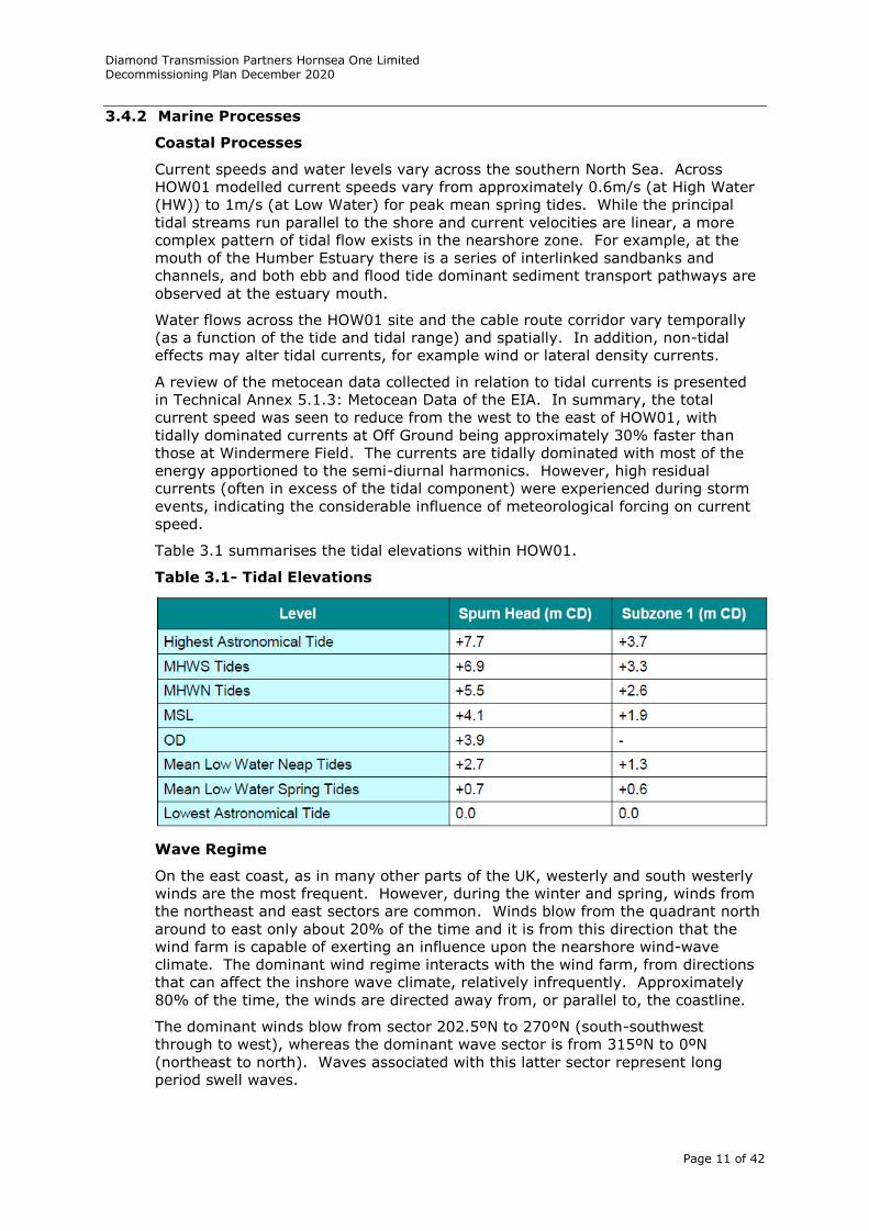
A review of the metocean data collected in relation to tidal currents is presented
in Technical Annex 5.1.3: Metocean Data of the EIA. In summary, the total
current speed was seen to reduce from the west to the east of HOW01, with
tidally dominated currents at Off Ground being approximately 30% faster than
those at Windermere Field. The currents are tidally dominated with most of the
energy apportioned to the semi-diurnal harmonics. However, high residual
currents (often in excess of the tidal component) were experienced during storm
events, indicating the considerable influence of meteorological forcing on current
speed.
Table 3.1 summarises the tidal elevations within HOW01.
Table 3.1- Tidal Elevations
Wave Regime
On the east coast, as in many other parts of the UK, westerly and south westerly
winds are the most frequent. However, during the winter and spring, winds from
the northeast and east sectors are common. Winds blow from the quadrant north
around to east only about 20% of the time and it is from this direction that the
wind farm is capable of exerting an influence upon the nearshore wind-wave
climate. The dominant wind regime interacts with the wind farm, from directions
that can affect the inshore wave climate, relatively infrequently. Approximately
80% of the time, the winds are directed away from, or parallel to, the coastline.
The dominant winds blow from sector 202.5ºN to 270ºN (south-southwest
through to west), whereas the dominant wave sector is from 315ºN to 0ºN
(northeast to north). Waves associated with this latter sector represent long
period swell waves.
Diamond Transmission Partners Hornsea One Limited Decommissioning Plan December 2020
Page 12 of 42
Since wind-waves originate from meteorological forcing, the wave regime is highly
episodic and exhibits strong seasonal variation. In deep water, waves will move
across the sea surface without major modification, but as they move into
shallower water, refraction, shoaling (wave steepening) and eventually wave
breaking will occur. Across the many shallow banks of the southern North Sea,
maximum wave heights are also likely to become ‘depth limited’ with shoaling and
wave breaking occurring, especially around low tide.
3.4.3 Biological Environment: Subtidal and Intertidal Benthic Ecology
Designated Areas
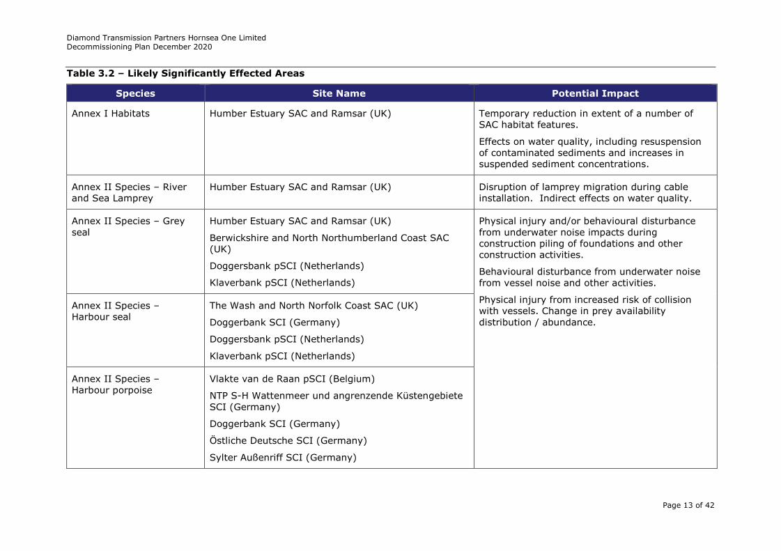
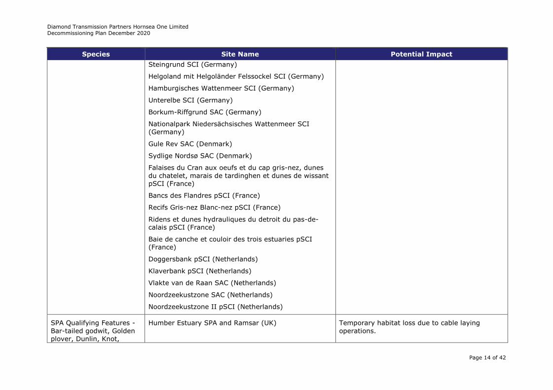
A Habitats Regulations Assessment (“HRA”) was undertaken as part of the DCO
application. The HRA considers the potential impacts upon European protected
sites, primarily these include Special Areas of Conservation (“SAC”) and Special
Protection Areas (“SPA”). Included within the assessment are the sites / features
listed in Table 3.2.
Diamond Transmission Partners Hornsea One Limited Decommissioning Plan December 2020
Page 13 of 42
Table 3.2 – Likely Significantly Effected Areas
Species Site Name Potential Impact
Annex I Habitats Humber Estuary SAC and Ramsar (UK) Temporary reduction in extent of a number of
SAC habitat features.
Effects on water quality, including resuspension
of contaminated sediments and increases in
suspended sediment concentrations.
Annex II Species – River
and Sea Lamprey
Humber Estuary SAC and Ramsar (UK) Disruption of lamprey migration during cable
installation. Indirect effects on water quality.
Annex II Species – Grey
seal
Humber Estuary SAC and Ramsar (UK)
Berwickshire and North Northumberland Coast SAC
(UK)
Doggersbank pSCI (Netherlands)
Klaverbank pSCI (Netherlands)
Physical injury and/or behavioural disturbance
from underwater noise impacts during
construction piling of foundations and other
construction activities.
Behavioural disturbance from underwater noise
from vessel noise and other activities.
Physical injury from increased risk of collision
with vessels. Change in prey availability
distribution / abundance.
Annex II Species –
Harbour seal
The Wash and North Norfolk Coast SAC (UK)
Doggerbank SCI (Germany)
Doggersbank pSCI (Netherlands)
Klaverbank pSCI (Netherlands)
Annex II Species –
Harbour porpoise
Vlakte van de Raan pSCI (Belgium)
NTP S-H Wattenmeer und angrenzende Küstengebiete
SCI (Germany)
Doggerbank SCI (Germany)
Östliche Deutsche SCI (Germany)
Sylter Außenriff SCI (Germany)
Diamond Transmission Partners Hornsea One Limited Decommissioning Plan December 2020
Page 14 of 42
Species Site Name Potential Impact
Steingrund SCI (Germany)
Helgoland mit Helgoländer Felssockel SCI (Germany)
Hamburgisches Wattenmeer SCI (Germany)
Unterelbe SCI (Germany)
Borkum-Riffgrund SAC (Germany)
Nationalpark Niedersächsisches Wattenmeer SCI
(Germany)
Gule Rev SAC (Denmark)
Sydlige Nordsø SAC (Denmark)
Falaises du Cran aux oeufs et du cap gris-nez, dunes
du chatelet, marais de tardinghen et dunes de wissant
pSCI (France)
Bancs des Flandres pSCI (France)
Recifs Gris-nez Blanc-nez pSCI (France)
Ridens et dunes hydrauliques du detroit du pas-de-
calais pSCI (France)
Baie de canche et couloir des trois estuaries pSCI
(France)
Doggersbank pSCI (Netherlands)
Klaverbank pSCI (Netherlands)
Vlakte van de Raan SAC (Netherlands)
Noordzeekustzone SAC (Netherlands)
Noordzeekustzone II pSCI (Netherlands)
SPA Qualifying Features -
Bar-tailed godwit, Golden
plover, Dunlin, Knot,
Humber Estuary SPA and Ramsar (UK) Temporary habitat loss due to cable laying
operations.
Diamond Transmission Partners Hornsea One Limited Decommissioning Plan December 2020
Page 15 of 42
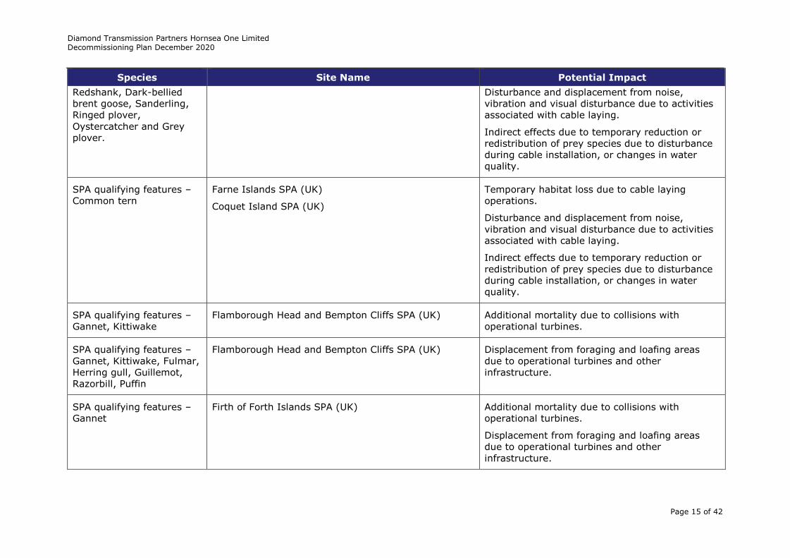
Species Site Name Potential Impact
Redshank, Dark-bellied
brent goose, Sanderling,
Ringed plover,
Oystercatcher and Grey
plover.
Disturbance and displacement from noise,
vibration and visual disturbance due to activities
associated with cable laying.
Indirect effects due to temporary reduction or
redistribution of prey species due to disturbance
during cable installation, or changes in water
quality.
SPA qualifying features –
Common tern
Farne Islands SPA (UK)
Coquet Island SPA (UK)
Temporary habitat loss due to cable laying
operations.
Disturbance and displacement from noise,
vibration and visual disturbance due to activities
associated with cable laying.
Indirect effects due to temporary reduction or
redistribution of prey species due to disturbance
during cable installation, or changes in water
quality.
SPA qualifying features –
Gannet, Kittiwake
Flamborough Head and Bempton Cliffs SPA (UK) Additional mortality due to collisions with
operational turbines.
SPA qualifying features –
Gannet, Kittiwake, Fulmar,
Herring gull, Guillemot,
Razorbill, Puffin
Flamborough Head and Bempton Cliffs SPA (UK) Displacement from foraging and loafing areas
due to operational turbines and other
infrastructure.
SPA qualifying features –
Gannet
Firth of Forth Islands SPA (UK) Additional mortality due to collisions with
operational turbines.
Displacement from foraging and loafing areas
due to operational turbines and other
infrastructure.
Diamond Transmission Partners Hornsea One Limited Decommissioning Plan December 2020
Page 16 of 42
Benthic Fauna
Sandy sediment communities dominated much of the HOW01 benthic ecology
study area, and were generally found to have more impoverished infaunal
communities than the coarse and mixed sediment communities, with lower
abundances and diversity of polychaetes and bivalve molluscs. The habitats
identified were typical of exposed or tide swept coasts and the dominance of
species such as the bivalve mollusc C. gibba, which in large abundances may be
indicative of unstable substrates (Crema et al., 1991) suggest that these areas
may be subject to seasonal or occasional environmental disturbances (Hrs-
Brenko, 2006). This would correlate with the observation that these habitats are
found in association with the sand dune fields in these areas. Epifaunal
communities in these areas were generally absent but, where present, were
species poor and characterised by a predominantly mobile species such as
echinoderms. The occasional cobble or pebble in these areas were colonised by
cnidarians and bryozoans, but these were typically rare in these sediments. The
results of the site specific surveys are supported by the Humber REC which
identified the EUNIS habitat A5.25(4) Infaunal polychaetes with burrowing
bivalves and amphipods in circalittoral fine sand as the dominant habitat over the
areas coinciding with the Project One benthic ecology study area.
The areas of deeper water to the north of the HOW01 benthic ecology study area,
although still predominantly sand, had a higher proportion of mud in the sediment
and supported communities dominated by infaunal and epifaunal brittlestars and
high abundances of burrowing bivalves. Muddier areas to the northeast of the
HOW01 benthic ecology study area also supported high abundances of the
Norway lobster Nephrops.
The coarse sediments which dominated the central and eastern parts of the
HOW01 benthic ecology study area, on the whole, had diverse infaunal
communities, similar in many places to those found within mixed sediments, with
a range of polychaete species present together with bivalve molluscs,
echinoderms and crustaceans. The epifaunal communities were, for the most
part, as sparse as those observed in the sandy sediments characterised by mobile
species, including echinoderms with rare occurrences of sessile epifauna in areas
where attachment to hard substrate could be made (i.e., on cobbles, pebbles or
gravel). The epifaunal communities in the coarse sediment habitats along the
export cable route corridor however, were more diverse than those found in the
rest of the HOW01 benthic ecology study area with more frequent occurrences of
hydroids and bryozoans on due to the greater availability of hard substrate. The
two occurrences of A. islandica, which is listed by OSPAR as a threatened and/or
declining species for the Greater North Sea (OSPAR Region II), were in coarse
sediments in the eastern end of the export cable route corridor and the north
eastern part of Subzone 1. As one of these specimens was a spat rather than a
juvenile of this species, and given the low occurrence in the grab samples, it is
unlikely that the HOW01 benthic ecology study area is of particular importance for
this species within the OSPAR Region II.
The mixed sediment substrate communities found within the Subzone 1 and the
wider HOW01 benthic ecology study area were largely similar to the coarse
sediment communities, and there was a high degree of overlap in the species
present. The mixed sediment communities on the export cable route corridor
differed by being dominated by non-reef forming S. spinulosa. The infaunal
communities associated with this tube-building polychaete were the most diverse
and numerically abundant communities observed throughout the HOW01 benthic
ecology study area, rich in polychaetes, crustaceans, molluscs and echinoderms.
The epifaunal components of these communities were also highly diverse with rich
communities of bryozoans, ascidians, anemones, shrimps and crabs.
Diamond Transmission Partners Hornsea One Limited Decommissioning Plan December 2020
Page 17 of 42
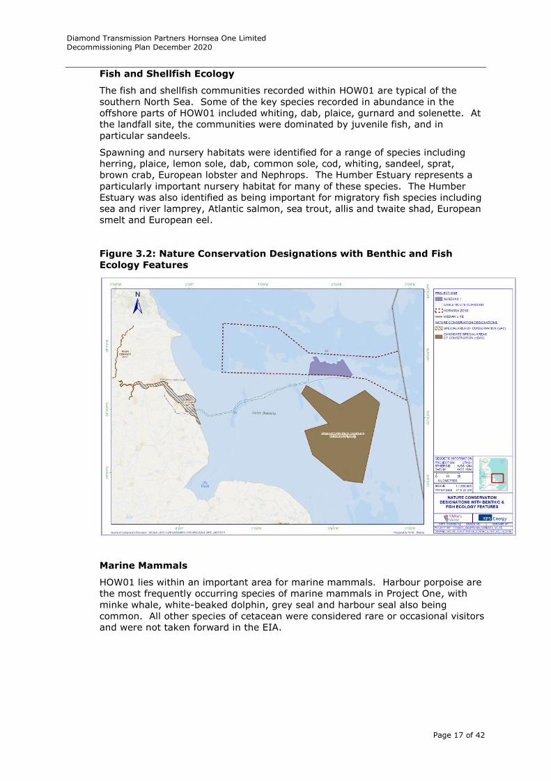
Fish and Shellfish Ecology
The fish and shellfish communities recorded within HOW01 are typical of the
southern North Sea. Some of the key species recorded in abundance in the
offshore parts of HOW01 included whiting, dab, plaice, gurnard and solenette. At
the landfall site, the communities were dominated by juvenile fish, and in
particular sandeels.
Spawning and nursery habitats were identified for a range of species including
herring, plaice, lemon sole, dab, common sole, cod, whiting, sandeel, sprat,
brown crab, European lobster and Nephrops. The Humber Estuary represents a
particularly important nursery habitat for many of these species. The Humber
Estuary was also identified as being important for migratory fish species including
sea and river lamprey, Atlantic salmon, sea trout, allis and twaite shad, European
smelt and European eel.
Figure 3.2: Nature Conservation Designations with Benthic and Fish
Ecology Features
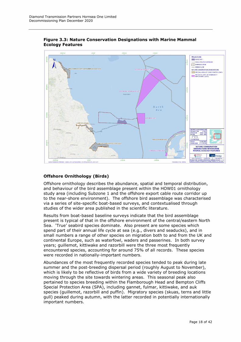
Marine Mammals
HOW01 lies within an important area for marine mammals. Harbour porpoise are
the most frequently occurring species of marine mammals in Project One, with
minke whale, white-beaked dolphin, grey seal and harbour seal also being
common. All other species of cetacean were considered rare or occasional visitors
and were not taken forward in the EIA.
Diamond Transmission Partners Hornsea One Limited Decommissioning Plan December 2020
Page 18 of 42
Figure 3.3: Nature Conservation Designations with Marine Mammal
Ecology Features
Offshore Ornithology (Birds)
Offshore ornithology describes the abundance, spatial and temporal distribution,
and behaviour of the bird assemblage present within the HOW01 ornithology
study area (including Subzone 1 and the offshore export cable route corridor up
to the near-shore environment). The offshore bird assemblage was characterised
via a series of site-specific boat-based surveys, and contextualised through
studies of the wider area published in the scientific literature.
Results from boat-based baseline surveys indicate that the bird assemblage
present is typical of that in the offshore environment of the central/eastern North
Sea. ‘True’ seabird species dominate. Also present are some species which
spend part of their annual life cycle at sea (e.g., divers and seaducks), and in
small numbers a range of other species on migration both to and from the UK and
continental Europe, such as waterfowl, waders and passerines. In both survey
years; guillemot, kittiwake and razorbill were the three most frequently
encountered species, accounting for around 75% of all records. These species
were recorded in nationally-important numbers.
Abundances of the most frequently recorded species tended to peak during late
summer and the post-breeding dispersal period (roughly August to November),
which is likely to be reflective of birds from a wide variety of breeding locations
moving through the site towards wintering areas. This seasonal peak also
pertained to species breeding within the Flamborough Head and Bempton Cliffs
Special Protection Area (SPA), including gannet, fulmar, kittiwake, and auk
species (guillemot, razorbill and puffin). Migratory species (skuas, terns and little
gull) peaked during autumn, with the latter recorded in potentially internationally
important numbers.
Diamond Transmission Partners Hornsea One Limited Decommissioning Plan December 2020
Page 19 of 42
3.5 Offshore Human Environment
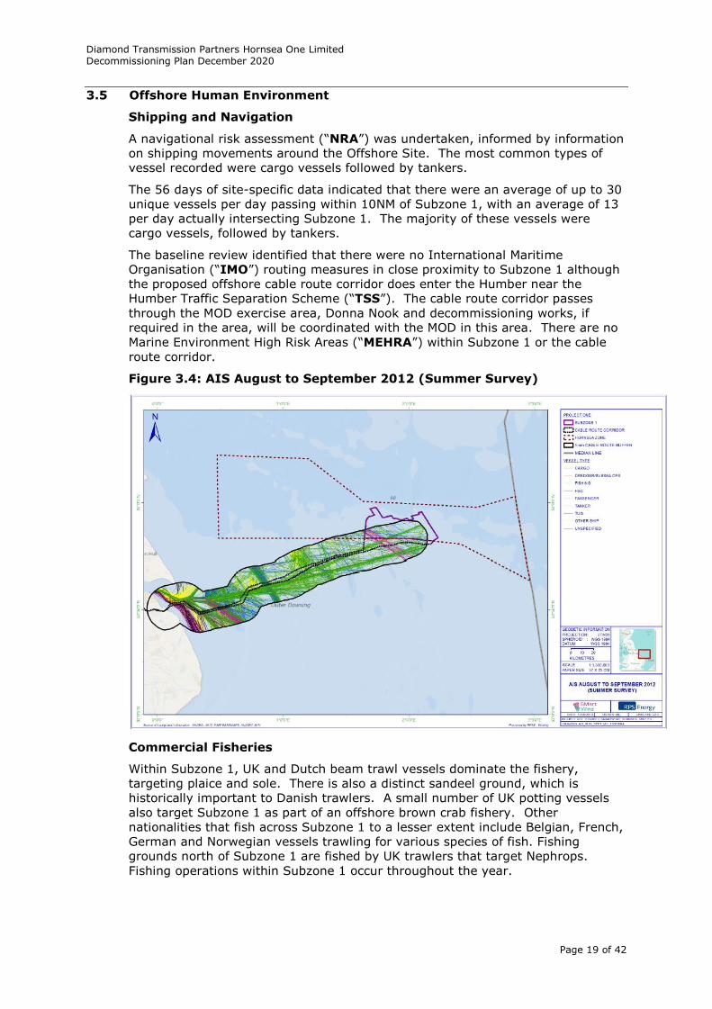
Shipping and Navigation
A navigational risk assessment (“NRA”) was undertaken, informed by information
on shipping movements around the Offshore Site. The most common types of
vessel recorded were cargo vessels followed by tankers.
The 56 days of site-specific data indicated that there were an average of up to 30
unique vessels per day passing within 10NM of Subzone 1, with an average of 13
per day actually intersecting Subzone 1. The majority of these vessels were
cargo vessels, followed by tankers.
The baseline review identified that there were no International Maritime
Organisation (“IMO”) routing measures in close proximity to Subzone 1 although
the proposed offshore cable route corridor does enter the Humber near the
Humber Traffic Separation Scheme (“TSS”). The cable route corridor passes
through the MOD exercise area, Donna Nook and decommissioning works, if
required in the area, will be coordinated with the MOD in this area. There are no
Marine Environment High Risk Areas (“MEHRA”) within Subzone 1 or the cable
route corridor.
Figure 3.4: AIS August to September 2012 (Summer Survey)
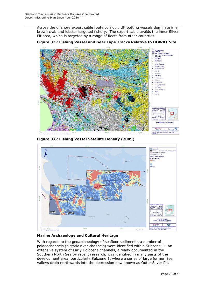
Commercial Fisheries
Within Subzone 1, UK and Dutch beam trawl vessels dominate the fishery,
targeting plaice and sole. There is also a distinct sandeel ground, which is
historically important to Danish trawlers. A small number of UK potting vessels
also target Subzone 1 as part of an offshore brown crab fishery. Other
nationalities that fish across Subzone 1 to a lesser extent include Belgian, French,
German and Norwegian vessels trawling for various species of fish. Fishing
grounds north of Subzone 1 are fished by UK trawlers that target Nephrops.
Fishing operations within Subzone 1 occur throughout the year.
Diamond Transmission Partners Hornsea One Limited Decommissioning Plan December 2020
Page 20 of 42
Across the offshore export cable route corridor, UK potting vessels dominate in a
brown crab and lobster targeted fishery. The export cable avoids the inner Silver
Pit area, which is targeted by a range of fleets from other countries.
Figure 3.5: Fishing Vessel and Gear Type Tracks Relative to HOW01 Site
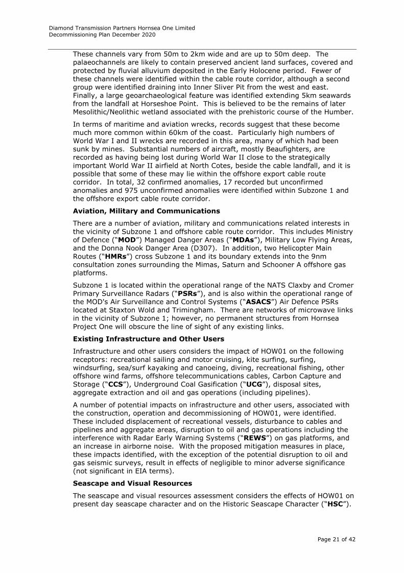
Figure 3.6: Fishing Vessel Satellite Density (2009)
Marine Archaeology and Cultural Heritage
With regards to the geoarchaeology of seafloor sediments, a number of
palaeochannels (historic river channels) were identified within Subzone 1. An
extensive system of Early Holocene channels, already documented in the
Southern North Sea by recent research, was identified in many parts of the
development area, particularly Subzone 1, where a series of large former river
valleys drain northwards into the depression now known as Outer Silver Pit.
Diamond Transmission Partners Hornsea One Limited Decommissioning Plan December 2020
Page 21 of 42
These channels vary from 50m to 2km wide and are up to 50m deep. The
palaeochannels are likely to contain preserved ancient land surfaces, covered and
protected by fluvial alluvium deposited in the Early Holocene period. Fewer of
these channels were identified within the cable route corridor, although a second
group were identified draining into Inner Sliver Pit from the west and east.
Finally, a large geoarchaeological feature was identified extending 5km seawards
from the landfall at Horseshoe Point. This is believed to be the remains of later
Mesolithic/Neolithic wetland associated with the prehistoric course of the Humber.
In terms of maritime and aviation wrecks, records suggest that these become
much more common within 60km of the coast. Particularly high numbers of
World War I and II wrecks are recorded in this area, many of which had been
sunk by mines. Substantial numbers of aircraft, mostly Beaufighters, are
recorded as having being lost during World War II close to the strategically
important World War II airfield at North Cotes, beside the cable landfall, and it is
possible that some of these may lie within the offshore export cable route
corridor. In total, 32 confirmed anomalies, 17 recorded but unconfirmed
anomalies and 975 unconfirmed anomalies were identified within Subzone 1 and
the offshore export cable route corridor.
Aviation, Military and Communications
There are a number of aviation, military and communications related interests in
the vicinity of Subzone 1 and offshore cable route corridor. This includes Ministry
of Defence (“MOD”) Managed Danger Areas (“MDAs”), Military Low Flying Areas,
and the Donna Nook Danger Area (D307). In addition, two Helicopter Main
Routes (“HMRs”) cross Subzone 1 and its boundary extends into the 9nm
consultation zones surrounding the Mimas, Saturn and Schooner A offshore gas
platforms.
Subzone 1 is located within the operational range of the NATS Claxby and Cromer
Primary Surveillance Radars (“PSRs”), and is also within the operational range of
the MOD's Air Surveillance and Control Systems (“ASACS”) Air Defence PSRs
located at Staxton Wold and Trimingham. There are networks of microwave links
in the vicinity of Subzone 1; however, no permanent structures from Hornsea
Project One will obscure the line of sight of any existing links.
Existing Infrastructure and Other Users
Infrastructure and other users considers the impact of HOW01 on the following
receptors: recreational sailing and motor cruising, kite surfing, surfing,
windsurfing, sea/surf kayaking and canoeing, diving, recreational fishing, other
offshore wind farms, offshore telecommunications cables, Carbon Capture and
Storage (“CCS”), Underground Coal Gasification (“UCG”), disposal sites,
aggregate extraction and oil and gas operations (including pipelines).
A number of potential impacts on infrastructure and other users, associated with
the construction, operation and decommissioning of HOW01, were identified.
These included displacement of recreational vessels, disturbance to cables and
pipelines and aggregate areas, disruption to oil and gas operations including the
interference with Radar Early Warning Systems (“REWS”) on gas platforms, and
an increase in airborne noise. With the proposed mitigation measures in place,
these impacts identified, with the exception of the potential disruption to oil and
gas seismic surveys, result in effects of negligible to minor adverse significance
(not significant in EIA terms).
Seascape and Visual Resources
The seascape and visual resources assessment considers the effects of HOW01 on
present day seascape character and on the Historic Seascape Character (“HSC”).
Diamond Transmission Partners Hornsea One Limited Decommissioning Plan December 2020
Page 22 of 42
The present day seascape and HSC were characterised by site-specific surveys
from viewpoint locations, as well as a desktop study.
The visual characteristics of Subzone 1 and the offshore export cable route
corridor are relatively homogenous, with a lack of visibility to coastal areas, due
to the distance from the shore. The offshore area is generally open, with
occasional views of offshore structures such as gas platforms, and regular
patterns of use by sea-going vessels for a variety of purposes (e.g., recreational
cruising, commercial ferry routes, commercial fishing activity etc.). Air combat
training takes place over the majority of the study area. There are no national or
regional seascape designations within the seascape and visual resources study
area.
Subzone 1 lies within two broad HSC types; Navigation and Offshore Industry.
Similarly, the offshore export cable route corridor passes largely through areas
with Navigation or Offshore Industry broad character designations. The only
exceptions to this, is close to the shore, which is identified as Military and Coastal
Industry.
4 Description of Items to be Decommissioned
As part of the windfarm construction the OFTO assets were constructed in a way
that it is possible to decommission them at the end of its operational life
(approximately 25 years3), in order to fulfil regulatory requirements at
construction consenting stage.
The following decommissioning measures are based on today’s known techniques
and have been proposed with regard to:
Decommissioning of Offshore Renewable Energy Installations Under the
Energy Act 2004 - Guidance notes for industry (England and Wales) – March
2019;
The Best Practicable Environmental Option (“BPEO”);
OSPAR guidance documents on offshore wind farms;
IMO ‘Guidelines and Standards for the Removal of Offshore Installations and
Structures on the Continental Shelf and in the Exclusive Economic Zone’;
Government guidance notes for decommissioning offshore oil and gas
installations in compliance with OSPAR Convention for the Protection of the
Marine Environment of the North-East Atlantic Decision 98/3;
UNCLOS and OSPAR obligations;
Safety of surface and subsurface navigation;
Other users of the sea, and
Health and safety considerations.
Components left in situ following decommissioning will be aligned with standards
set out by the IMO that specify that, an installation or structure need not be
entirely removed if:
It would not involve extreme cost;
It is not technically feasible (however, the design and construction should be
such that entire removal would be feasible);
It would involve an unacceptable risk to personnel; and
3 Note Ofgem OFTO regime requires OFTOs to be prepared to decommission the
transmission asset after 25 years.
Diamond Transmission Partners Hornsea One Limited Decommissioning Plan December 2020
Page 23 of 42
It would involve an unacceptable risk to the environment.
In addition, DTPH will also apply the following principles:
Table 4.1: Guiding Principles
Guiding Principles Comments
Minimise environmental
impact
In considering decommissioning measures, the BPEO
will be chosen in order to minimise impact on the
environment at an acceptable cost.
Safety at all times for all The highest levels of health and safety will be followed
throughout the project lifecycle. Safe practices will be
followed in implementing decommissioning solutions.
Maximise reuse of
materials
DTPH will aim to maximise the reuse of waste
material from the decommissioning phase and will pay
full regard to the ‘waste hierarchy’, see Table 6.3.
Consideration of the
rights and needs of
legitimate users of the
sea
The rights and needs of other users are respected by
DTPH. Decommissioning activities will seek to
minimise the impact on stakeholders and emphasis
will be placed on clear and open communication.
Follow Polluter Pays
Principle
DTPH decommissioning and waste management
provisions acknowledge our responsibility to incur the
costs associated with our impact on the environment.
5 Description of Items to be Decommissioned
The items covered in this section for decommissioning by DTPH are:
Three Offshore Substation Platforms (“OSP”) (including jacket and ALL
components on the platform);
One Reactive Compensation Station (“RCS”) (including jacket and ALL
components on the platform);
Three offshore export cables; and
Interlink cable.
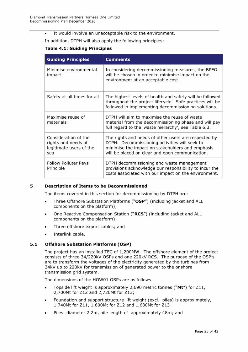
5.1 Offshore Substation Platforms (OSP)
The project has an installed TEC of 1,200MW. The offshore element of the project
consists of three 34/220kV OSPs and one 220kV RCS. The purpose of the OSP’s
are to transform the voltages of the electricity generated by the turbines from
34kV up to 220kV for transmission of generated power to the onshore
transmission grid system.
The dimensions of the HOW01 OSPs are as follows:
Topside lift weight is approximately 2,690 metric tonnes (“Mt”) for Z11,
2,700Mt for Z12 and 2,720Mt for Z13;
Foundation and support structure lift weight (excl. piles) is approximately,
1,740Mt for Z11, 1,600Mt for Z12 and 1,630Mt for Z13
Piles: diameter 2.2m, pile length of approximately 48m; and
Diamond Transmission Partners Hornsea One Limited Decommissioning Plan December 2020
Page 24 of 42
Area of topside is approximately: 52m long x 36m wide x 52m high.
Located on each OSP is:
Two main transformer including coolers;
One Shunt Reactor;
Medium voltage (“MV”) switchgear bays;
220kV Gas Insulated Switchgear (“GIS”) bays;
Auxiliary transformers and two earthing resistors;
Control and communication room (“SCADA”)
LV & utility room;
Public room Accommodation (emergency)Laydown areas; and
Cable deck.
Figure 5.1: HOW01 OSP
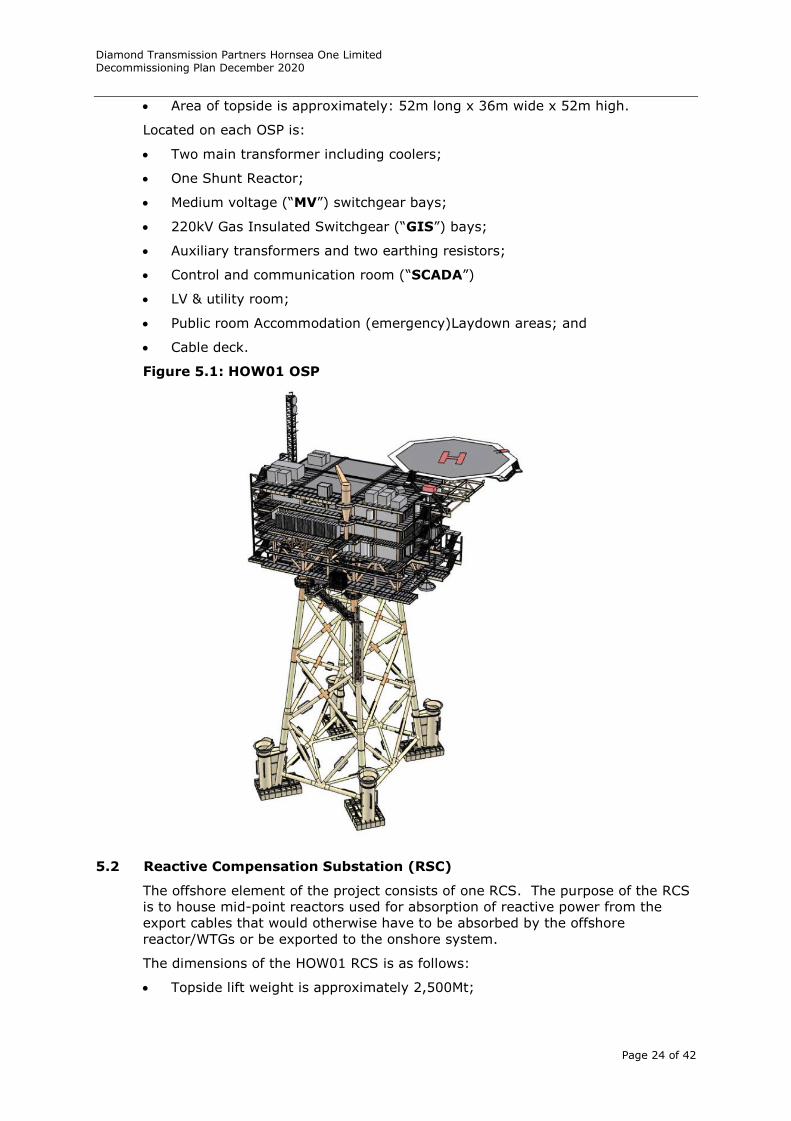
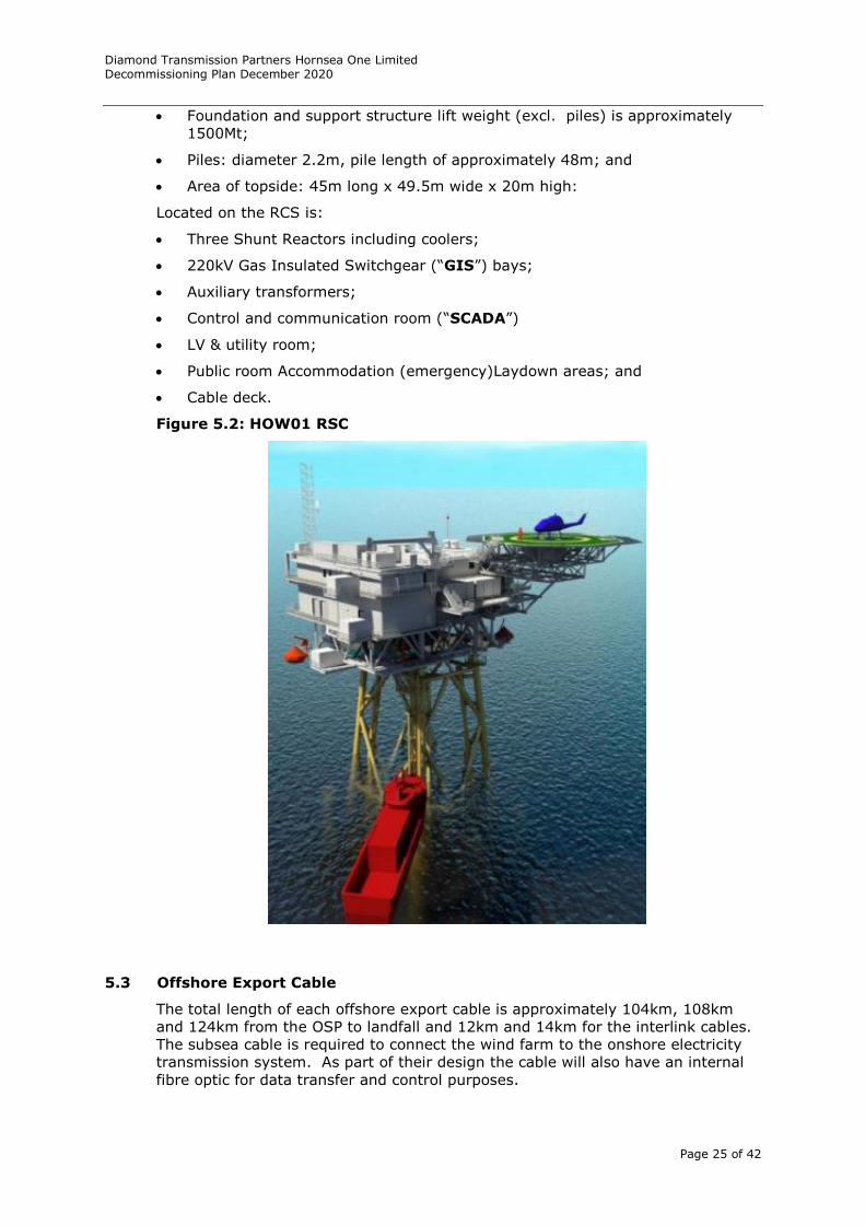
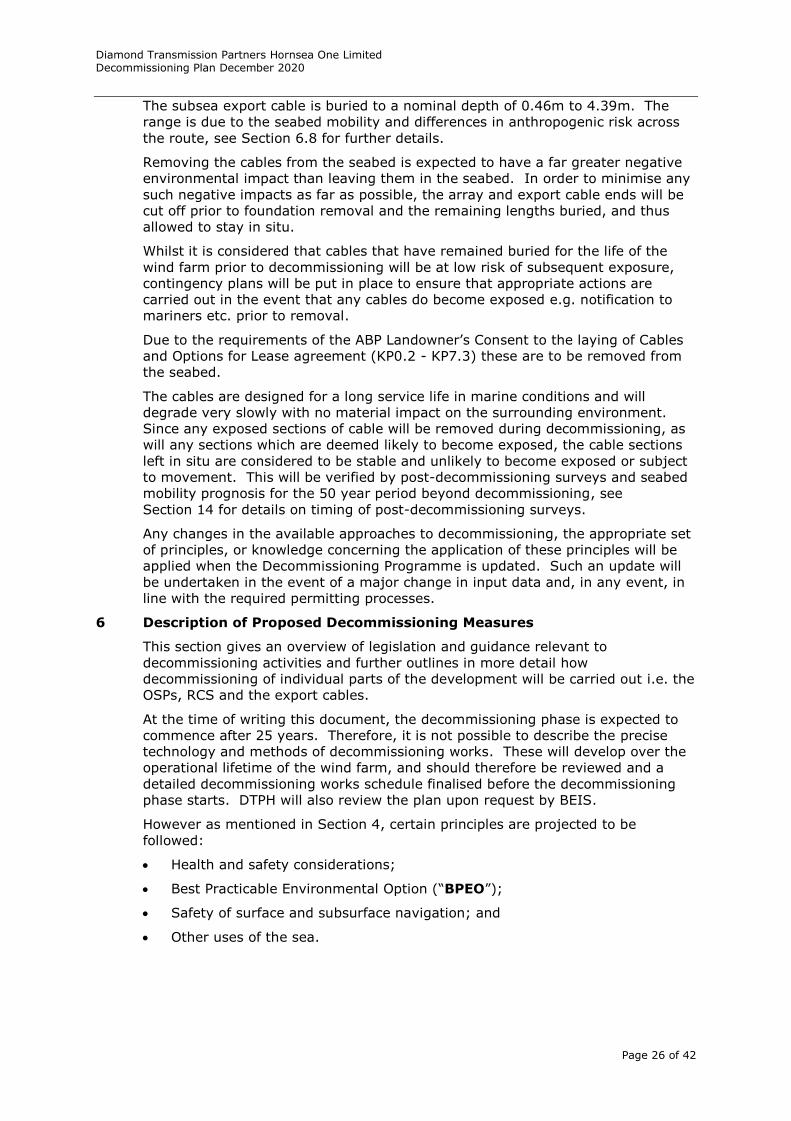
5.2 Reactive Compensation Substation (RSC)
The offshore element of the project consists of one RCS. The purpose of the RCS
is to house mid-point reactors used for absorption of reactive power from the
export cables that would otherwise have to be absorbed by the offshore
reactor/WTGs or be exported to the onshore system.
The dimensions of the HOW01 RCS is as follows:
Topside lift weight is approximately 2,500Mt;
Diamond Transmission Partners Hornsea One Limited Decommissioning Plan December 2020
Page 25 of 42
Foundation and support structure lift weight (excl. piles) is approximately
1500Mt;
Piles: diameter 2.2m, pile length of approximately 48m; and
Area of topside: 45m long x 49.5m wide x 20m high:
Located on the RCS is:
Three Shunt Reactors including coolers;
220kV Gas Insulated Switchgear (“GIS”) bays;
Auxiliary transformers;
Control and communication room (“SCADA”)
LV & utility room;
Public room Accommodation (emergency)Laydown areas; and
Cable deck.
Figure 5.2: HOW01 RSC
5.3 Offshore Export Cable
The total length of each offshore export cable is approximately 104km, 108km
and 124km from the OSP to landfall and 12km and 14km for the interlink cables.
The subsea cable is required to connect the wind farm to the onshore electricity
transmission system. As part of their design the cable will also have an internal
fibre optic for data transfer and control purposes.
Diamond Transmission Partners Hornsea One Limited Decommissioning Plan December 2020
Page 26 of 42
The subsea export cable is buried to a nominal depth of 0.46m to 4.39m. The
range is due to the seabed mobility and differences in anthropogenic risk across
the route, see Section 6.8 for further details.
Removing the cables from the seabed is expected to have a far greater negative
environmental impact than leaving them in the seabed. In order to minimise any
such negative impacts as far as possible, the array and export cable ends will be
cut off prior to foundation removal and the remaining lengths buried, and thus
allowed to stay in situ.
Whilst it is considered that cables that have remained buried for the life of the
wind farm prior to decommissioning will be at low risk of subsequent exposure,
contingency plans will be put in place to ensure that appropriate actions are
carried out in the event that any cables do become exposed e.g. notification to
mariners etc. prior to removal.
Due to the requirements of the ABP Landowner’s Consent to the laying of Cables
and Options for Lease agreement (KP0.2 - KP7.3) these are to be removed from
the seabed.
The cables are designed for a long service life in marine conditions and will
degrade very slowly with no material impact on the surrounding environment.
Since any exposed sections of cable will be removed during decommissioning, as
will any sections which are deemed likely to become exposed, the cable sections
left in situ are considered to be stable and unlikely to become exposed or subject
to movement. This will be verified by post-decommissioning surveys and seabed
mobility prognosis for the 50 year period beyond decommissioning, see
Section 14 for details on timing of post-decommissioning surveys.
Any changes in the available approaches to decommissioning, the appropriate set
of principles, or knowledge concerning the application of these principles will be
applied when the Decommissioning Programme is updated. Such an update will
be undertaken in the event of a major change in input data and, in any event, in
line with the required permitting processes.
6 Description of Proposed Decommissioning Measures
This section gives an overview of legislation and guidance relevant to
decommissioning activities and further outlines in more detail how
decommissioning of individual parts of the development will be carried out i.e. the
OSPs, RCS and the export cables.
At the time of writing this document, the decommissioning phase is expected to
commence after 25 years. Therefore, it is not possible to describe the precise
technology and methods of decommissioning works. These will develop over the
operational lifetime of the wind farm, and should therefore be reviewed and a
detailed decommissioning works schedule finalised before the decommissioning
phase starts. DTPH will also review the plan upon request by BEIS.
However as mentioned in Section 4, certain principles are projected to be
followed:
Health and safety considerations;
Best Practicable Environmental Option (“BPEO”);
Safety of surface and subsurface navigation; and
Other uses of the sea.
Diamond Transmission Partners Hornsea One Limited Decommissioning Plan December 2020
Page 27 of 42
6.1 Adherence to relevant legislation and guidance
The decommissioning measures are based on known techniques of today and
have been proposed taking into consideration the following key UK and
international legislation and guidance notes:
Decommissioning of offshore renewable energy installations under the Energy
Act 2004: Guidance notes for industry (England and Wales) March 2019;
Guidelines and Standards for the Removal of Offshore Installations and
Structures on the Continental Shelf and in the Exclusive Economic Zone,
International Maritime Organisation (IMO), 19 October 1989;
Guidance Notes for Industry: Decommissioning of Offshore Installations and
Pipelines under the Petroleum Act 1998, DECC;
OSPAR guidance documents on offshore wind farms;
Guidelines for Environmental Risk Assessment and Management, Defra,
September 2002; and
United Nations Convention on the Law of the Sea (UNCLOS), 1982.
Other relevant legislation includes:
Hazardous Waste Regulations 2005;
Marine and Coastal Access Act 2009;
The Water Resources Act 1991;
The Conservation of Habitats and Species Regulations 2010;
The disposal or recovery of waste on land, principally under Part II of the
Environmental Protection Act 1990, other legislation relating to the carriage
and transfer of waste and, where appropriate, the Hazardous Waste
Regulations 2005; and relevant health and safety legislation;
London Convention 1972 and the 1996 Protocol, relating to the prevention of
marine pollution by dumping of wastes;
Construction (Design and Management) Regulations (CDM) 2015; and
Appropriate H&S Regulations.
6.2 Phasing and Co-ordination of Decommissioning
The phasing and detailed programme for decommissioning will be defined and
submitted to BEIS in advance of decommissioning.
6.3 Plan of Works and Integration
A detailed final Decommissioning Programme will be prepared two years ahead of
the proposed decommissioning date and will incorporate the results of a detailed
recent EIA, thus allowing sufficient time to implement any measures arising into
the final Decommissioning Programme. The process supporting the EIA will
include pre-decommissioning surveys. The plan of work will include detailed
method statement together with project specific hazard and risk assessments.
DTPH will also liaise with other developers in the region to ensure potential
synergies for decommissioning facilities are investigated.
6.4 Decommissioning of Offshore Substation Platforms and Reactive
Compensation Stations
It is planned that the structure for the OSP and RCS will be removed in its
entirety including the foundations. There are some structures that may be left
Diamond Transmission Partners Hornsea One Limited Decommissioning Plan December 2020
Page 28 of 42
under the seabed i.e. cables and foundation bottom pieces whereby removal may
result in greater impact on the environment than leaving them in situ.
The items to be decommissioned are:
All of the topside equipment, transformers and reactor;
(As the transformers and reactor are oil filled, they and the various other
components including generators and fuel storage, will be transported to an
onshore facility for dismantling, with constituent parts processed for reuse,
recycling and disposal. This will be performed in conjunction with the
generator);
The topside’s support structure;
The jacket structure, including all appurtenances such as J-Tubes and boat
access system;
The piles will be cut at such a depth below the surface of the seabed that the
remaining parts do not pose a danger for shipping or fishing vessels, even if
sediment should become relocated. Following the cutting operation the
foundations and the jacket structure may be removed as a single structure
after the removal of the topside; and
The interlink cable and turbine interconnecting cables adjacent to the
substructure will be cut at a point below the surface of the seabed to allow
the cable to remain buried (cut sections will be removed with minimal
disruption to the seabed).
It is expected that the OSPs and RCS will be decommissioned in two main stages,
comprising the complete removal, firstly of the topside, followed by removal also
of the jacket foundation.
Prior to removal of the topside, a number of preparatory activities will be
conducted including:
De-energise and isolate required electrical control and power cables from
National Grid and SCADA system;
It is proposed that the oil filled transformers and reactor are braced for sea
transportation, transformer and reactor oil levels can be reduced in
components like the conservator tank and cooler fins to deal with a liquid
load;
Dismantle terminations for export and array cables; removal of all cables
back to cable deck, or seabed;
Removal of all unsecured loose items from the topside;
Containment and/or removal of potentially hazardous/polluting fluids. An
agreement will be made with the Gas Insulated Switchgear (“GIS”) supplier
or another competent contractor to ensure the safe removal of the SF6 Gas;
Certification of lifting points; and
Cutting welded stab-in connections between topside and foundation.
A Heavy Lift Barge Vessel (“HLV”) will be used to dismantle the topside and
transport the structure ashore for further dismantling.
The process of decommissioning of the OSPs and RCS is likely to involve the
following second stage sequence:
A HLV lifts the topside module onto an adjacent barge;
Topside is transported back to port where the topside is transferred to the
quayside;
Diamond Transmission Partners Hornsea One Limited Decommissioning Plan December 2020
Page 29 of 42
Topside will be processed for recycling and or disposal as appropriate; and
Jacket piles will be cut off at such a depth below the surface of the seabed
that the remaining parts do not pose a danger for shipping or fishing vessels,
even if sediments should become relocated, the method used could be either
water cutting or remote thermal cutting.
Complete removal of the pile below the seabed is considered neither practical nor
environmentally desirable. The appropriate depth for removal would depend
upon the sea-bed conditions and site characteristics at the time of
decommissioning. This is in line with the IMO standards as complete removal of
the foundations would involve an unacceptable risk to the marine environment
and is likely to involve extreme cost. If an obstruction exists above the sea bed
or an obstruction appears following decommissioning which is attributable to the
wind farm, this obstruction will be marked by the owner so as not to present a
hazard to other sea users. The marking will remain in place until such time as
the obstruction is removed or is no longer considered to be a hazard to other sea
users. The monitoring of this obstruction will be built into the decommissioning
monitoring and maintenance programme.
The general target for cutting of the jacket piles will be at such a depth below the
surface of the seabed that the remaining parts do not pose a danger for shipping
or fishing vessels, even if sediments should become relocated. When assessing
the possibility of cutting below the seabed, it is important to consider the need to
overcome frictional forces acting on the pile. Considerable excavation will have to
take place, approximately two meters in diameter for every meter in depth below
the seabed.
Once cut the jacket will then be lifted onto a barge and transported back to port
for recycling or sold off as scrap metal.
Items contained within the topside will be processed for recycling accordingly or
disposed as appropriate.
All hazardous waste will be handled accordingly and disposed of in accordance
with its waste classification.
6.5 Decommissioning of Export Cables and Interlink Cables
The decision whether or not to remove the cables will be taken closer to the end
of the project’s lifetime and will be subject to consultation as part of an
application for consent to cover decommissioning activities. If cables are left
in-situ, the ends will be weighted down and buried at the current depth to ensure
that no navigational risk arises in the sense that fishing gear or anchor would
interface with the as left cables. Also, only export cables and interlink cables
which are buried to a depth considered to be safe will be left in-situ. Exposed
cables will be removed or buried to a secure depth. Due to the requirements of
the ABP Landowner’s Consent to the laying of Cables and Options for Lease
agreement (KP0.2 - KP7.3) these are to be removed from the seabed.
Where a cable is removed on request, the sequence for removal is anticipated to
be:
Identify the location of the cables that need to be removed;
Seabed material may need to be removed to locate the cable, likely to be
carried out using a water jetting tool similar to that used during cable
installation e.g. mass flow excavator. Buried cables will be located using a
grapnel to lift them from the seabed. Alternatively, or in addition, it may be
necessary to use an Remote Operated Vehicle (“ROV”) to cut and/or attach a
lifting attachment to the cable so that it can be recovered to the vessel;
Diamond Transmission Partners Hornsea One Limited Decommissioning Plan December 2020
Page 30 of 42
The recovery vessel will either 'peel out' the cable as it moves backwards
along the cable route whilst picking it up on the winch or cable engines, or, if
the seabed is very stiff/hard it may first under-run the cable with a
suspended sheave block to lift the cable from the seabed. The use of a
suspended sheave block could be carried out before by a separate vessel
such as a tug prior to the recovery vessel ‘peeling out’ the cable;
The recovery vessel will either spool the recovered cable into a carousel or
chop it into lengths as it is brought on-board before transport to shore; and
Parts will be processed for reuse, recycle or disposal.
6.6 Rock Berms
The base case assumption for rock berms is that they will be left in situ. DTPH
considers that it is best practice to leave rock berms in place to preserve the
marine habitat that has established over the operational life of the wind farm, on
the assumption that to do so would not have a detrimental impact on the
environment, conservation aims, the safety of navigation and other uses of the
sea.
6.7 Summary of Proposed Decommissioning Measures
A summary of the proposed decommissioning measures for the offshore
components of the DTPH are outlined in Table 6.1a and 6.1b.
Table 6.1a: Summary of Proposed Decommissioning Measures for DTPH
Component Proposed decommissioning measures
OSP and RCS Topside Complete removal
Jacket Cut off at such a depth below the surface of the
seabed that the remaining parts do not pose a
danger for shipping or fishing vessels.
Offshore export cable Cut off at the base of the platform, the remaining
cable will be weighted down and buried at such a
depth below the surface of the seabed that the
remaining parts do not pose a danger for shipping or
fishing vessels.
Cable removal from ABP port jurisdiction.
Offshore interlink cable Cut off at the base of the platform, the remaining
cable will be weighted down and buried at such a
depth below the surface of the seabed that the
remaining parts do not pose a danger for shipping or
fishing vessels.
Table 6.2: Decommissioning Programme Technical and Environmental
Summary
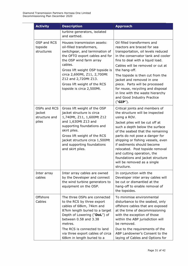
Activity Description Approach
Disconnection Transmission assets
disconnected from National
Grid Electricity Transmission
(“NGET”) system and wind
Undertaken in accordance with
the safety rules in place at the
time.
Diamond Transmission Partners Hornsea One Limited Decommissioning Plan December 2020
Page 31 of 42
Activity Description Approach
turbine generators, isolated
and earthed.
OSP and RCS
topside
structures
Houses transmission assets:
oil-filled transformers,
switchgear, and termination of
the OFTO export cables and for
the OSP wind farm array
cables.
Gross lift weight OSP topside is
circa 2,690Mt, Z11, 2,700Mt
Z12 and 2,720Mt Z13.
Gross lift weight of the RCS
topside is circa 2,500Mt.
Oil filled transformers and
reactors are braced for sea
transportation, oil levels reduced
in the conservator tank and cooler
fins to deal with a liquid load.
Cables will be removed or cut at
the hang-off.
The topside is then cut from the
jacket and removed in one
piece. Parts will be processed
for reuse, recycling and disposal
in line with the waste hierarchy
and Good Industry Practice
(“GIP”).
OSPs and RCS
jacket
structure and
piles
Gross lift weight of the OSP
jacket structure is circa
1,740Mt, Z11, 1,600Mt Z12
and 1,630Mt Z13 and
supporting foundations and
skirt piles.
Gross lift weight of the RCS
jacket structure circa 1,500Mt
and supporting foundations
and skirt piles.
Critical joints and members of
the structure will be inspected
using a ROV.
Jacket piles will be cut off at
such a depth below the surface
of the seabed that the remaining
parts do not pose a danger for
shipping or fishing vessels, even
if sediments should become
relocated. Post topside removal
and cutting operation, the
foundations and jacket structure
will be removed as a single
structure.
Inter array
cables
Inter array cables are owned
by the Developer and connect
the wind turbine generators to
equipment on the OSP.
In conjunction with the
Developer inter array cables will
be cut or dismantled at the
hang-off to enable removal of
the topsides.
Offshore
Cables
The three OSPs are connected
to the RCS by three export
cables of 68km, 74km and
87km length buried to a target
Depth of Lowering (“DoL”) of
between 0.58 and 3.38
metres.
The RCS is connected to land
via three export cables of circa
68km in length buried to a
To minimise environmental
disturbance to the seabed, only
offshore cables that are exposed
at the time of decommissioning
with the exception of those
within the ABP jurisdiction will
be removed.
Due to the requirements of the
ABP Landowner’s Consent to the
laying of Cables and Options for
Diamond Transmission Partners Hornsea One Limited Decommissioning Plan December 2020
Page 32 of 42
Activity Description Approach
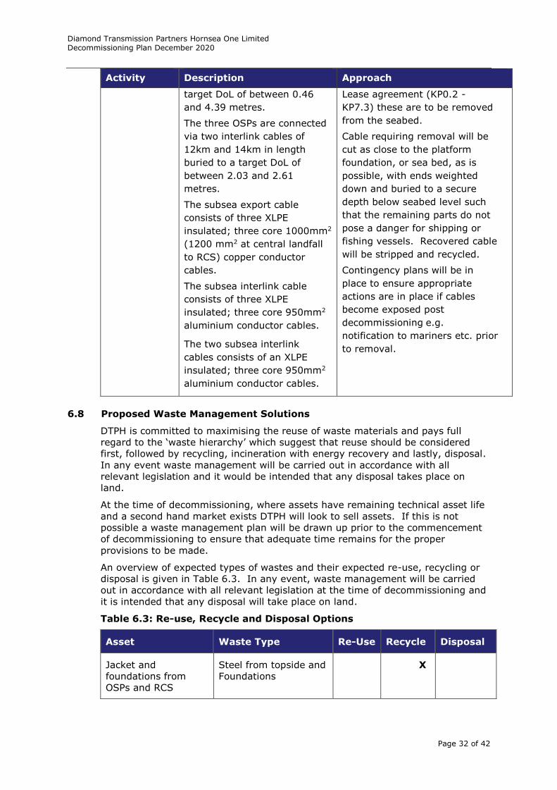
target DoL of between 0.46
and 4.39 metres.
The three OSPs are connected
via two interlink cables of
12km and 14km in length
buried to a target DoL of
between 2.03 and 2.61
metres.
The subsea export cable
consists of three XLPE
insulated; three core 1000mm2
(1200 mm2 at central landfall
to RCS) copper conductor
cables.
The subsea interlink cable
consists of three XLPE
insulated; three core 950mm2
aluminium conductor cables.
The two subsea interlink
cables consists of an XLPE
insulated; three core 950mm2
aluminium conductor cables.
Lease agreement (KP0.2 -
KP7.3) these are to be removed
from the seabed.
Cable requiring removal will be
cut as close to the platform
foundation, or sea bed, as is
possible, with ends weighted
down and buried to a secure
depth below seabed level such
that the remaining parts do not
pose a danger for shipping or
fishing vessels. Recovered cable
will be stripped and recycled.
Contingency plans will be in
place to ensure appropriate
actions are in place if cables
become exposed post
decommissioning e.g.
notification to mariners etc. prior
to removal.
6.8 Proposed Waste Management Solutions
DTPH is committed to maximising the reuse of waste materials and pays full
regard to the ‘waste hierarchy’ which suggest that reuse should be considered
first, followed by recycling, incineration with energy recovery and lastly, disposal.
In any event waste management will be carried out in accordance with all
relevant legislation and it would be intended that any disposal takes place on
land.
At the time of decommissioning, where assets have remaining technical asset life
and a second hand market exists DTPH will look to sell assets. If this is not
possible a waste management plan will be drawn up prior to the commencement
of decommissioning to ensure that adequate time remains for the proper
provisions to be made.
An overview of expected types of wastes and their expected re-use, recycling or
disposal is given in Table 6.3. In any event, waste management will be carried
out in accordance with all relevant legislation at the time of decommissioning and
it is intended that any disposal will take place on land.
Table 6.3: Re-use, Recycle and Disposal Options
Asset Waste Type Re-Use Recycle Disposal
Jacket and
foundations from
OSPs and RCS
Steel from topside and
Foundations
X
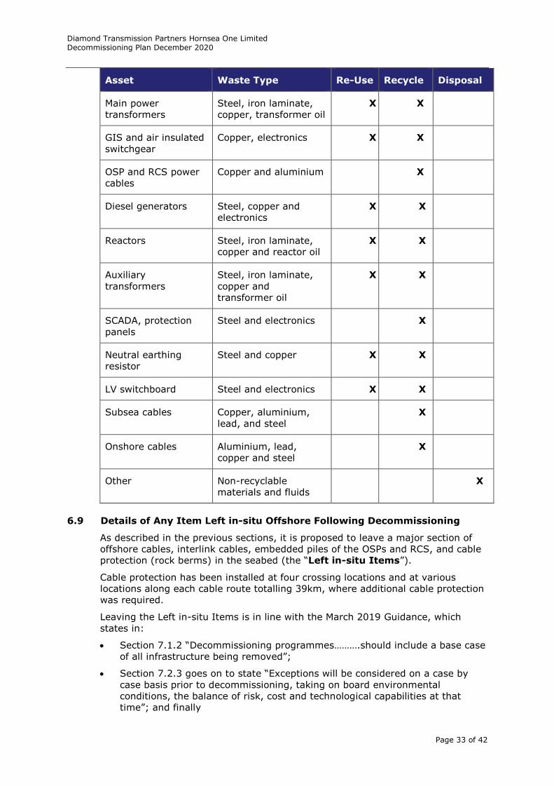
Diamond Transmission Partners Hornsea One Limited Decommissioning Plan December 2020
Page 33 of 42
Asset Waste Type Re-Use Recycle Disposal
Main power
transformers
Steel, iron laminate,
copper, transformer oil
X X
GIS and air insulated
switchgear
Copper, electronics X X
OSP and RCS power
cables
Copper and aluminium X
Diesel generators Steel, copper and
electronics
X X
Reactors Steel, iron laminate,
copper and reactor oil
X X
Auxiliary
transformers
Steel, iron laminate,
copper and
transformer oil
X X
SCADA, protection
panels
Steel and electronics X
Neutral earthing
resistor
Steel and copper X X
LV switchboard Steel and electronics X X
Subsea cables Copper, aluminium,
lead, and steel
X
Onshore cables Aluminium, lead,
copper and steel
X
Other Non-recyclable
materials and fluids
X
6.9 Details of Any Item Left in-situ Offshore Following Decommissioning
As described in the previous sections, it is proposed to leave a major section of
offshore cables, interlink cables, embedded piles of the OSPs and RCS, and cable
protection (rock berms) in the seabed (the “Left in-situ Items”).
Cable protection has been installed at four crossing locations and at various
locations along each cable route totalling 39km, where additional cable protection
was required.
Leaving the Left in-situ Items is in line with the March 2019 Guidance, which
states in:
Section 7.1.2 “Decommissioning programmes……….should include a base case
of all infrastructure being removed”;
Section 7.2.3 goes on to state “Exceptions will be considered on a case by
case basis prior to decommissioning, taking on board environmental
conditions, the balance of risk, cost and technological capabilities at that
time”; and finally
Diamond Transmission Partners Hornsea One Limited Decommissioning Plan December 2020
Page 34 of 42
Section 7.2.6 states “Where less than full decommissioning is proposed,
developers/owners will need to engage with other regulators (such as the
Marine Management Organisation and Natural Resources Wales in respect of
Marine Licences and Maritime and Coastguard Agency and the General
Lighthouse Authority in connection with navigational risk) and their landlord
on the acceptability of the proposals.”
In line with the March 2019 Guidance Section 7.2.2 the basis of the Left in-situ
Items is that one of the four IMO standards where non-removal or partial removal
may be considered is met, being:
1. The installation or structure will serve a new use, whether for renewable
energy generation or for another purpose, such as enhancement of a living
resource (provided it would not be detrimental to other aims, such as
conservation);
2. Entire removal would involve an unacceptable risk to personnel;
3. Entire removal would involve an unacceptable risk to the marine
environment; and
4. Entire removal would involve extreme costs.
The primary reasons for leaving the Left in-situ Items in the seabed are:
IMO Standard 2:
1. Decommissioning of the Left in-situ Items will require the involvement of
divers in significant and dangerous operations e.g. in preparatory work for
cable/embedded pile removal, installation/recovery/snagging works of any
under runners used during the cable removal etc. and the lift operation
required during the removal of cable protection (rock berm removal has
never been done to date) etc.
IMO Standard 3:
1. Cable Protection - leaving cable protection in-situ on the seabed is
associated with certain positive effects (leaving the exposed habitat and
benthic community that will have likely colonised it in place, and avoiding the
increased vessel disturbance/damage and sediment effects associated with
removing the material). However, leaving cable protection in-situ is also
associated with certain adverse effects (the enduring loss of the original
biotopes and potential scouring of surrounding natural seabed sediments).
On balance, avoiding impacts arising from removal and the positive impacts
of colonisation outweigh the negligible to minor adverse impacts of continued
seabed loss and potential scour.
In addition, cable protection will also trap sand migration on the seabed. It is
assumed that some form of localised dredging, or more likely the use of a
remotely operated underwater excavator tool as used in cable re-burial would
be used to pre-blast or clear the sand away from the cable protection with
associated disturbance/damage and sediment effects associated with
removing the material.
2. Jacket Piles - complete removal of the pile below the seabed with currently
proven technology is considered neither practical, nor environmentally
desirable due to the considerable excavation that will have to take place,
approximately two meters diameter for every meter in depth below the
seabed, with piles buried to a depth of approximately 48 metres resulting in
disturbance of 96 metres.
3. Export Cables – The use of a remotely operated underwater excavator to
blast or clear the sand away from the buried cable prior to removal will cause
Diamond Transmission Partners Hornsea One Limited Decommissioning Plan December 2020
Page 35 of 42
unnecessary damage and disturbance to the seabed where cables have been
proved to have been adequately buried.
The methodology to determine the export cable seabed mobility and
minimum depth of lowering of the cable, to ensure the cable is adequately
protected is detailed in documents ‘2.2.4.1.21_HOW01 - Export Cable Route
and Interlink Cable Route - Seabed Change Assessment (00045067_C).pdf,
and . 2.2.5.1.10 HOW01 Export and Interlink Cable Routes Burial Strategy
Report (02126734_B).pdf. The ‘Seabed Change Assessment Report’
considers a period of 25 years.
In summary, the Reference Seabed Level (“RSBL”) for every metre point of
the route is calculated for the lowest expected elevation of the seabed level
over the lifetime of the project (25 years) hence any cable buried lower than
the RSBL level is expected to remain adequately buried and protected against
seabed mobility.
Based on the installed burial depths, the total length of cable, which has not
been buried deeper than the RSBL is 0.103km out of a total route length of
443.554km.
Note that the RSBL is considered achieved where rock protection has been
installed regardless of the initial depth of lowering that was achieved.
The sections where the RSBL has not been achieved represent a total of
approximately 0.02% of the total installed route length of approximately
444km. The remaining cable, which has been buried deeper than the RSBL,
or is protected by rock, is forecast to remain buried for the lifetime of the
project being 25 years and is therefore considered stable, however this will
be monitored throughout the lifetime of the assets. At the time of
decommissioning any cable that has remained adequately buried for a period
in excess of 25 years will be expected to remain buried for the foreseeable
future and will be evidenced by a final RSBL assessment prior to
decommissioning.
For the sections of the export cables buried above the RSBL level and
forecast to become exposed over a 25 year period, the Developer states
RSBL is overly conservative in these areas as they are close to a boundary
between two morphology zones on a slope and that no remedial work is
expected here. DTPH analysis confirms this statement.
The cable which has been buried deeper than the RSBL is forecast to remain
buried for the lifetime of the assets and is therefore considered stable,
however this will be monitored throughout the lifetime of the assets. At the
time of decommissioning any cable that has remained adequately buried for a
period in excess of 25 years will be expected to remain buried for the
foreseeable future and will be evidenced by a final RSBL assessment prior to
decommissioning.
Cable which has not been installed deeper than the RSBL will be reviewed by
DTPH (as part of the overall cable monitoring) at each update of the
Decommissioning Programme. If exposures occur during the life of the
project and are not forecast to be naturally reburied by bedform movement,
then DTPH will undertake remedial burial works. This additional lowering
may result in an overall depth of lowering which ensures long-term stability
of the cable and no future exposures.
IMO Standard 2 and 3:
4. Cable protection removal at crossing locations is undesirable owing to the risk
of damaging the third party infrastructure that the cable protection is
protecting, which includes other power cables and pipelines. Damaging third
Diamond Transmission Partners Hornsea One Limited Decommissioning Plan December 2020
Page 36 of 42
party assets may lead to a major pollution incident and may involve divers in
the significant and dangerous repair work operations.
IMO Standard 4:
5. The cost of decommissioning the export cable that is adequately buried, more
than doubles the forecast cost of decommissioning the offshore transmission
assets, and as such will not present value for money for the UK consumer
who would pay these costs through the offshore transmission tender revenue
stream.
An updated EIA will be produced at the Decommissioning Programme year 23 to
review and confirm assumptions based on the environmental conditions at the
time. DTPH will also enter into discussions with BEIS and The Crown Estate
regarding long term monitoring and residual liability of any infrastructure left in
situ at this time.
6.10 Lighting and marking
During the decommissioning of the Hornsea One Offshore Wind Farm, appropriate
aviation and nautical marking and illumination will be applied.
In accordance with the Hornsea One consent under Section 36 of the Electricity
Act 1989, DTPH is committed to exhibiting the appropriate marks and lights
during the decommissioning of the project.
In relation to aviation safety, the shape, colour and character of the lighting will
be compliant with the Air Navigation Order 2005, or as otherwise directed by the
Civil Aviation Authority or the relevant legislation at the time.
In relation to navigational safety, lights and marks will be agreed with Trinity
House, in consultation with the Maritime and Coastguard Agency prior to
decommissioning to specify any obstruction marking that may be required during
the removal operations. In the event that any obstruction is left on site, which
may be considered to present a hazard to navigation, the necessary and specified
marking will be provided.
7 Environmental Impact Assessment
The Developer for HOW01 completed an EIA in 2013. Table 7.1 summarises the
impacts from the decommissioning phase.
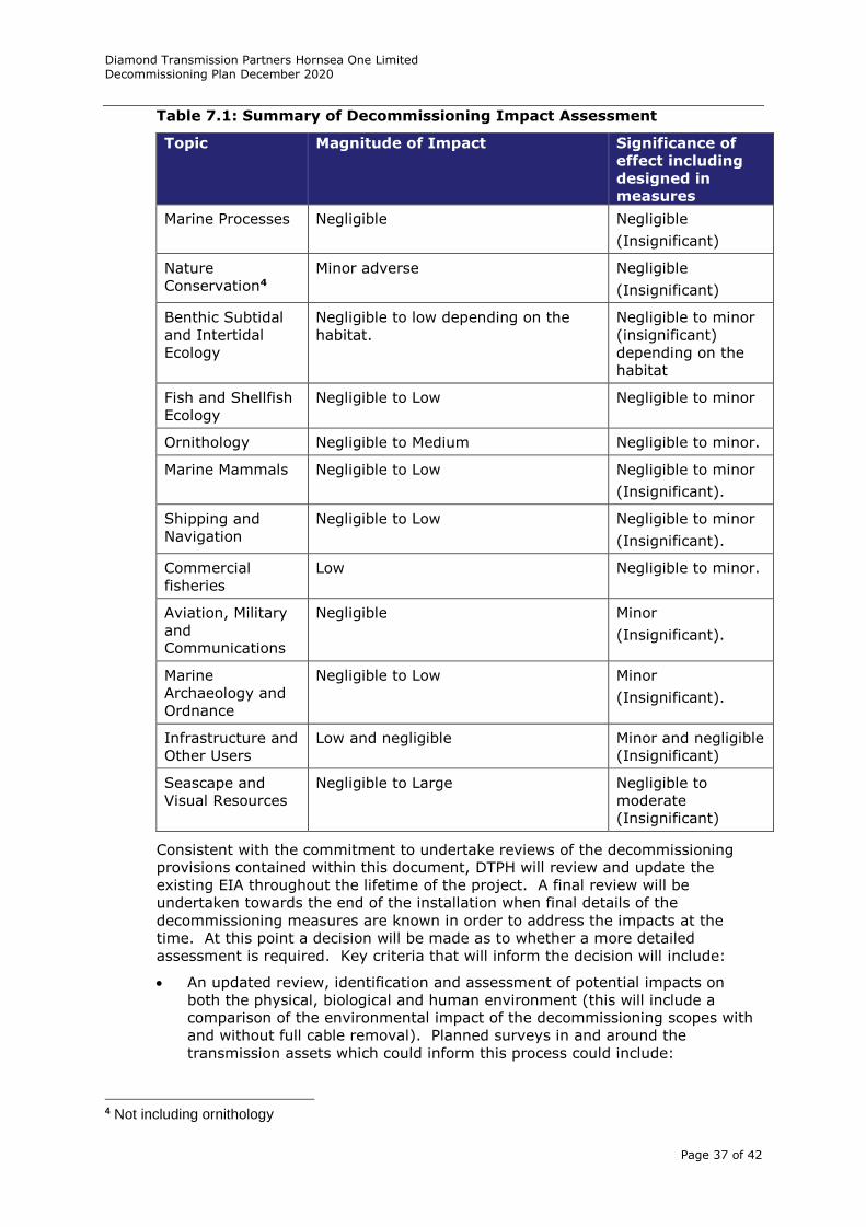
Diamond Transmission Partners Hornsea One Limited Decommissioning Plan December 2020
Page 37 of 42
Table 7.1: Summary of Decommissioning Impact Assessment
Topic Magnitude of Impact Significance of
effect including
designed in
measures
Marine Processes Negligible Negligible
(Insignificant)
Nature
Conservation4
Minor adverse Negligible
(Insignificant)
Benthic Subtidal
and Intertidal
Ecology
Negligible to low depending on the
habitat.
Negligible to minor
(insignificant)
depending on the
habitat
Fish and Shellfish
Ecology
Negligible to Low Negligible to minor
Ornithology Negligible to Medium Negligible to minor.
Marine Mammals Negligible to Low Negligible to minor
(Insignificant).
Shipping and
Navigation
Negligible to Low Negligible to minor
(Insignificant).
Commercial
fisheries
Low Negligible to minor.
Aviation, Military
and
Communications
Negligible Minor
(Insignificant).
Marine
Archaeology and
Ordnance
Negligible to Low Minor
(Insignificant).
Infrastructure and
Other Users
Low and negligible Minor and negligible
(Insignificant)
Seascape and
Visual Resources
Negligible to Large Negligible to
moderate
(Insignificant)
Consistent with the commitment to undertake reviews of the decommissioning
provisions contained within this document, DTPH will review and update the
existing EIA throughout the lifetime of the project. A final review will be
undertaken towards the end of the installation when final details of the
decommissioning measures are known in order to address the impacts at the
time. At this point a decision will be made as to whether a more detailed
assessment is required. Key criteria that will inform the decision will include:
An updated review, identification and assessment of potential impacts on
both the physical, biological and human environment (this will include a
comparison of the environmental impact of the decommissioning scopes with
and without full cable removal). Planned surveys in and around the
transmission assets which could inform this process could include:
4 Not including ornithology
Diamond Transmission Partners Hornsea One Limited Decommissioning Plan December 2020
Page 38 of 42
Geophysical surveys side scan sonar (“SSS”) and Multibeam Echo
Sounder (“MBES”));
Geotechnical surveys;
Benthic grab/camera surveys;
Ornithological surveys;
Marine mammal monitoring; and
Fish surveys.
An updated review, identification and assessment of activities of other
legitimate users of the sea with the potential to be affected by
decommissioning. This is because the nature and/or intensity of human
activities taking place on/around the transmission assets, such as navigation
in and out of the Mersey Estuary, could have changed over the lifetime of the
project.
An updated review, identification and assessment of the potential impacts of
decommissioning on the local community, e.g. potential socio-economic
impacts.
An updated review, identification and assessment of potential impacts on
historic environment interests, in particular marine archaeological features.
If upon these additional reviews it is concluded that gaps exist in any of the topics
above, a specific EIA covering the decommissioning process will be prepared in
consultation with the relevant authorities. The EIA will list measures to avoid or
otherwise reduce or remedy adverse impacts where possible.
8 Consultation with Key Stakeholders and General Public
DTPH regards open and effective communication and consultation as an essential
element of owning and operating the asset. Carrying on with the good work and
relationships established by the Developer during the development and
construction phase, we will ensure that this is applied during the operational life
of the asset through to decommissioning.
DTPH proposes to seek the advice and opinions on the draft Decommissioning
Programme from a range of stakeholders including but not limited to:
The Crown Estate;
BEIS;
Local and national government including; East Lindsay District Council; West
Lindsay District Council; North East Lincolnshire District Council and North
Lincolnshire Council;
Port Authorities including Associated British Ports (“ABP”)
UK Hydrographic Office;
Ministry of Defence (Donna Nook exercise area)
Maritime and Coast Guard Agency;
Marine and Fisheries Agency;
Centre for Environment;
Health and Safety Executive (“HSE”)
Fisheries and Aquaculture Science;
North Eastern Inshore Fisheries and Conservation Authority;
Marine Management Organisation;
Diamond Transmission Partners Hornsea One Limited Decommissioning Plan December 2020
Page 39 of 42
Local businesses;
National Grid Electricity System Operator (“NGESO”)
NGET;
British Gas;
National Federation of Fishermen’s Organisation;
Local land and marine community;
Inshore fisheries and conservation Authority;
The Chamber of Shipping;
Joint Nature Conservation Committee;
National British Marine Aggregate Producers Association (“BMAPA”);
Historic England;
The Royal Yachting Associations; and
Trinity House.
All advice and opinions received through the consultation will be reviewed and
where applicable incorporated into the Draft Decommissioning Programme.
DTPH will apply for a separate decommissioning marine licence from Marine
Management Organisation at the time of decommissioning.
In accordance with the relevant clauses under Section 36 of the Energy Act 1989
and relevant conditions of the Marine Licence, DTPH will issue timely and efficient
Notice to Mariners and other navigational warnings of the position and nature of
the decommissioning activities that will be taking place. Efforts will be made to
ensure that this information reaches mariners of the shipping and fishing industry
as well as recreational mariners. The UK Hydrographic Office will be notified as
appropriate on the progress and completion of works.
9 Costs and Financial Security
Cost and financial security information is commercially confidential and therefore
not included in this Decommissioning Programme. Cost and financial security
information is provided separately to BEIS.
10 Proposed Decommissioning Schedule
It is proposed that decommissioning commences after year 25, coinciding with
the end of life of the asset based on its design life and the mid-life of The Crown
Estate lease.
As no offshore windfarm has been decommissioned to date worldwide, it is
difficult to anticipate the operational challenges, costs and precise timings of
works. Once other farms start to be decommissioned, it will provide valuable
information to DTPH on timings, costs and operational challenges to be faced.
Currently we anticipate Hornsea One offshore wind farm will be decommissioned
between 2045 and 2049 and will take 24 months to complete.
In line with project management guidelines and DTPH experience, we
acknowledge that the most important step in the decommissioning process is
advanced planning and having an option of decommissioning methods. Applying
the principles mentioned in earlier parts of this document, DTPH will carry out
regular reviews throughout the project lifecycle to take account of:
Information gathered during the course of construction and operation;
Changes in market conditions, international standards, the regulatory regime;
Diamond Transmission Partners Hornsea One Limited Decommissioning Plan December 2020
Page 40 of 42
Knowledge of environmental impacts, including any sediment shift since
construction, or new species entering the area;
New technology assessed against developmental status (e.g. prototype or
proven), efficiency both in terms of time and cost and health and safety and
environmental impacts;
New methods assessed against developmental status (e.g. prototype or
proven), efficiency both in terms of time and cost and heath safety and
environmental impacts;
Any relevant changes in nearby infrastructure or navigational routes; and
The latest cost estimates and the robustness of the financial security
arrangements.
DTPH intends to undertake internal reviews of the Decommissioning Programme
throughout the life of the project with an internal review of the Decommissioning
Programme before the commencement of the formal review in year 12 to ensure
the Decommissioning Programme and financial security estimates are up to date.
Formal review exercises will be undertaken with BEIS at the following times:
12-18 month before the first security provision is due; and
23 years following commencement of the transmission licence.
During the formal reviews DTPH will undertake a review of any items proposed to
be left in-situ following decommissioning.
In addition a formal review will be undertaken following any major work or when
a material change has occurred with the relevant authorities notified.
The final review will provide an opportunity to scrutinise the detail of the
decommissioning provisions in consultation with BEIS and key stakeholders
(including Marine Management Organisation), ensuring the impacts of the
decommissioning works have been adequately assessed and the schedule of
works and the costs associated are fully understood and agreed. This final review
will include the latest bathymetric survey data to confirm the cable burial depths
against the RSBL to demonstrate that any cable intended to be left in-situ is
adequately buried. At this stage consideration will also be given as to whether a
revised EIA and Appropriate Assessment are deemed necessary.
11 Project Management and Verification
The final Decommissioning Programme will provide information on how DTPH will
manage the implementation of the decommissioning works and also provide
assurance to the BEIS concerning progress and compliance. The final review of
this document and the proposed schedule of decommissioning works will be
undertaken towards the end of the operational lifetime (depending on repowering
taking place or not). This review will produce a Decommissioning Programme of
Works, including current knowledge of decommissioning methods, measures and
timing. The Decommissioning Programme will be made available to the public for
comment.
The project management of the decommissioning works will be undertaken with
the right level of rigor expected of such a project. DTPH envisages a single main
contractor for the decommissioning work and will also appoint an experienced and
highly qualified project management team to ensure the decommissioning work
proceeds on schedule and in accordance with the requirements of the
Decommissioning Programme.
A Decommissioning Report will be issued for the approval from the appropriate
regulatory authorities after the decommissioning phase is finished, in compliance
with the BEIS Guidance, summarising how the Programme has been carried out.
Diamond Transmission Partners Hornsea One Limited Decommissioning Plan December 2020
Page 41 of 42
As a minimum, this report will include:
Confirmation that the approved Decommissioning Programme has been
adhered to during the decommissioning works; otherwise, an explanation of
any major variances from the programme; this includes information of actual
costs of the works and an explanation of any major variances from the
forecast costs;
Information on the outcome of the decommissioning phase, including sea-bed
clearance;
Confirmation that relevant authorities have been notified, in case any
elements of the development remain protruding from the seabed, of
existence of such remains; and
Information of any appropriate aids to navigation have been installed, where
required, to overcome risks posed by such remains.
Upon completion, not more than four months after the decommissioning works,
the report will be provided to BEIS.
12 Sea-bed Clearance
In accordance with the Polluter Pays Principle (“PPP”), DTPH proposes to clear
the seabed in accordance with the provisions made in this Decommissioning
Programme and to collect and provide evidence of this.
Following the completion of decommissioning works, surveys will be carried out to
show that the site has been cleared. These surveys will enable identification and
subsequent recovery of any debris located on the sea-bed which may have arisen
from activities related to the project and which may pose a risk to navigation,
other users of the sea or the marine environment. It is currently intended that
side scan sonar will be used to identify debris, with an ROV deployed to
investigate and recover any potential identified.
The area to be covered will be determined prior to decommissioning but DTPH is
aware of the guidance for oil and gas installations which specifies a 500m radius
around any installation.
References will be made to ‘Archaeological No Build Areas’ in order that these are
not inadvertently cleared in the process of removing any debris. Analysis of the
survey data will also ensure that items for removal and disposal relate only to the
project. The appropriate competent authority will be approached regarding the
identification of other anomalies that may be of archaeological interest.
It is important that this process of collecting and presenting evidence that the site
is cleared is independent. DTPH proposes that an independent survey company
complete the surveys and that they report in parallel to both DTPH and BEIS.
13 Restoration of the Site
Following the successful completion of the decommissioning works, the DTPH site
will be restored, as far as reasonably practicable, to the condition it was in
pre-construction.
The key restoration works will include the following:
Securing and adequately covering all cut foundations; and
Ensuring that cable ends are adequately buried.
Active restoration relying on intervention with equipment is not proposed as it is
considered that such works present unnecessary and unacceptable risk to
personnel. For the export and interlink cables, it should be noted that the
currently envisaged option is to leave the cable buried in the seabed. Allowing
the seabed to ‘self-settle’ is considered sufficient and in proportion to the limited
Diamond Transmission Partners Hornsea One Limited Decommissioning Plan December 2020
Page 42 of 42
environmental impact of the proposed decommissioning. Should post
decommissioning surveys indicate that previously buried cables have become
exposed such that they pose a navigational risk, the exposed parts of the cable
would be cut away and removed from the seabed.
14 Post-decommissioning Monitoring, Maintenance and Management of the
Site
DTPH proposes to use an independent contractor to carry out surveys post
decommissioning. The scope will include identification and mitigation of any
unexpected risks to navigation and other users of the sea caused by materials left
on the seabed.
DTPH proposes to undertake magnetometer and geophysical surveys at the
completion of decommissioning, and subsequently in Year 1 and 2
post-decommissioning with a scope to survey in Year 4 and 6 based on findings
from the previous surveys. The area covered by the magnetometer and
geophysical surveys will be determined prior to decommissioning, but is expected
to be in the order of 500 metres around the offshore platforms and 25 metres
either side of each export cable route. We are also aware of oil and gas
installation guidance which specifies a 500 metres radius around any installation.
The survey interpretation reports will be provided to BEIS.
Should these surveys identify any residual elements from the project protruding
above the sea bed, DTPH will ensure that notification is given to the UK
Hydrographic Office so that suitable notation of a potential anchoring hazard can
be marked on relevant charts and mariners informed accordingly. Appropriate
measures will then be taken to remove or re-bury in order to avoid posing a risk
to mariners potentially using the area. The removal or reburial technique and
machinery will be decided depending on the type, size and location of the
elements, but will more likely mirror that used for the initial decommissioning
works.
15 Supporting Studies
Any supporting studies or investigations which are undertaken in support of
future Decommissioning Programmes will be included as annexes to the
Decommissioning Programme.
The following documents inform and support the decommissioning provisions
contained in this document:
Hornsea One Offshore Wind Farm Decommissioning Programme;
Decommissioning of offshore renewable installations under the Energy Act
2004: Guidance notes for the industry, BEIS, March 2019 (revised);
Marine and Coastal Access Act 2009;
Deemed marine licence granted as part of the DCO awarded 14 December
2014.
Section 36 Licence;
DCO granted December 2014;and
Hornsea One Offshore Wind Farm Environmental Statement July 2013.