Dial Indicator
27
Digimatic Indicator ABSOLUTE Digimatic Indicator ID-S 232 ABSOLUTE Digimatic Indicator ID-U 233 ABSOLUTE Digimatic Indicator ID-C 234 ABSOLUTE Digimatic Indicator ID-H 240 ABSOLUTE Digimatic Indicator ID-F 241 ABSOLUTE Digimatic Indicator ID-N/B 242 Dial Indicator 244 Special Dial Indicator 253 Dial Indicator (One Revolution Type) 254 Dial Indicator (Long Stroke Type) 256 Dial Indicator (Large Dial Face and Long Stroke Type) 258 ANSI/AGD Type Metric Dial Indicator 260 Hicator, Signal Hicator 261 Back Plunger Type Dial Indicator 262 Contact Point 264 Back 266 Spindle Lifting Lever and Cable 267 Color Spindle Cap 268 Limit Sticker 268 Dial Indicator Repair Tool Kit 269 Dial Indicator Crystal Setter 269 Dial Test Indicator Dial Test Indicator 270 Pocket Type Dial Test Indicator 276 Contact Point, Stem and Clamp Holder 278 Dial Indicator
-
Upload
antay-korakot -
Category
Documents
-
view
9 -
download
0
description
h
Transcript of Dial Indicator

231
ID-H
2046S
2109S-10
ID-N / ID-B
Caliper gage
Digimatic IndicatorABSOLUTE Digimatic Indicator ID-S 232ABSOLUTE Digimatic Indicator ID-U 233ABSOLUTE Digimatic Indicator ID-C 234ABSOLUTE Digimatic Indicator ID-H 240ABSOLUTE Digimatic Indicator ID-F 241ABSOLUTE Digimatic Indicator ID-N/B 242
Dial Indicator 244Special Dial Indicator 253Dial Indicator (One Revolution Type) 254Dial Indicator (Long Stroke Type) 256Dial Indicator (Large Dial Face and Long Stroke Type) 258ANSI/AGD Type Metric Dial Indicator 260Hicator, Signal Hicator 261Back Plunger Type Dial Indicator 262Contact Point 264Back 266Spindle Lifting Lever and Cable 267Color Spindle Cap 268Limit Sticker 268Dial Indicator Repair Tool Kit 269Dial Indicator Crystal Setter 269Dial Test IndicatorDial Test Indicator 270Pocket Type Dial Test Indicator 276Contact Point, Stem and Clamp Holder 278
Light-Weight Dial Thickness Gage 284Digimatic Caliper Gage 285Dial Caliper Gage 286Bench Gage 288Upright Gage 289Dial Snap Gage 290Female Screw Thread Comparator 291Roll Caliper 291Dial Tension Gage 292V-Block Set 292StandMagnetic Stand 293Dial Gage Stand 294Transfer Stand 295Granite Comparator Stand 296Comparator Stand 297Heavy Duty Comparator Stand 298
Dial Indicator

244
����������������������������������������������������
����
����
�����
�
�
�
�
�
�
�� �� �� �� �� �� �� �� �� ��� ��� ������
�� �� ��� ��� ��� ��� ���� ���� ���� ���� �����
�
�
�
�
�
�
�
�
����������������
��������������
��
��
��
��
��
����������������
����������
���������������������������������������������
�������������������������������������������
����������
������������������������������������������������
�
��
� �
�����������������������
�����������������������
Dial Indicator
Description of IconIcon Description
Reverse reading type suitable for depth and step measurement.
One revolution type for easy and error-free reading
Double scale spacing type, easy-on-the-eyes
Shockproof type
Waterproof type
With damper at lowest rest point
Jeweled bearing type
Peak retaining type
Long stem type
Dustproof type
With coaxial revolution counter
Back plunger type
Adjustable hand type
Double-face type
FEATURES: S Series• Revolutionary stem-bush design for trouble
free stem clamping (longer clamping range).
• No through screw-hole on the frame for high dust-resistance.
• Involute curved lifting lever for smooth movement of spindle and dovetail joint for tool-less connection.
• Grater rigidity in the bearing plate for reducing the retracing error (20%) and 4-screw mounting for increasing impact resistance.
Limit hand
Bezel clamp
Stem
Spindle
Contact point

245
����
�
���������
��
����
�
���
���
��
��
���������
�������
Dial IndicatorSERIES 1 — Compact One Revolution Type for Error-free Reading
Unlike many other dial indicators, the one-revolution dial indicator literally shows the entire spindle travel or range as one sweep of the hand, eliminating the possibility of reading errors due to miscounting the mul-tiple revolutions. With one-revolution dial indicators, "within tolerance" and "out-of-tolerance" can never misinterpretedAn unique shock-proof mechanism is incorporated, providing improved immunity to shock due to sudden spindle retraction caused by high impact.
(Refer to the page 9 for details.)
1929S1929S-601929S-62
1929S
Optional Accessory––––––: Backs (See page 266.)––––––: Contact points (See page 264.)
1900S-101900S-701900S-72
DIMENSION Unit: mm
Order No. A B C1929S 47.5 13.8 13.71929S-60 55.5 12.2 23.31929S-62 47.5 13.8 13.71900S-10 53.5 16.8 16.71900S-70 54.5 12.2 22.31900S-72 53.5 16.8 16.7
Note 1: Dimensions of the inch (ANSI/AGD Type) dial indicator partly differ from those of the metric (ISO/JIS Type) indicator.
Note 2: Inch (ANSI/AGD Type) dial indicator is provided with a stem of 3/8" dia. and #4-48UNF thread mount for the contact point.
ISO/JIS Type
One revolution type
������������������������������������ �����������������������������
������������������������������������ �����������������������������
ISO/JIS type
ANSI/AGD type
SPECIFICATIONSMetric
GraduationOrder No. Range
(range/rev) Accuracy Dial reading
Measuring force —
w/ lug Flat-back0.01mm 1929S 1929SB 1mm / 1.4mm ±11µm 50-0-50 1.4N or less — — — — ✔ —0.01mm 1929S-60 1929SB-60 1mm / 1.4mm ±11µm 50-0-50 1.4N or less — — ✔ — ✔ —0.01mm 1929S-62 1929SB-62 1mm / 1.4mm ±11µm 50-0-50 1.4N or less — — — ✔ ✔ —0.001mm 1900S-10 1900SB-10 0.1mm / 0.14mm ±6µm 50-0-50 1.5N or less — ✔ — — ✔ —0.001mm 1900S-70 1900SB-70 0.1mm / 0.14mm ±6µm 50-0-50 1.5N or less — ✔ ✔ — ✔ —0.001mm 1900S-72 1900SB-72 0.1mm / 0.14mm ±6µm 50-0-50 1.5N or less — ✔ — ✔ ✔ —
Inch
GraduationOrder No. Range
(range/rev) Accuracy Dial reading
Measuring force —
w/ lug Flat-back.0005” 1909S-62 1909SB-62 .04” / .055” ±.0005” 20-0-20 1.4N or less — — — ✔ ✔ —.0001” 1910S-72 1910SB-72 .006” / .0079” ±.0001” 3-0-3 1.4N or less — — — ✔ ✔ —
��������������������������
�����������������������������������
246
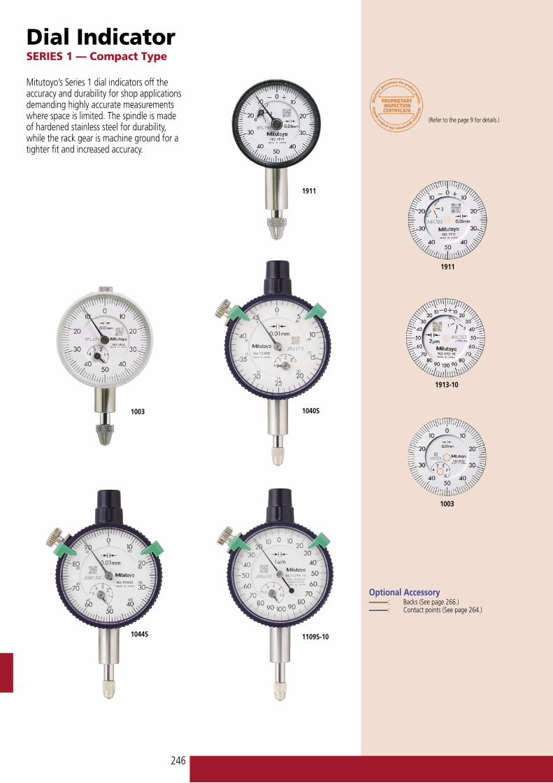
Dial IndicatorSERIES 1 — Compact Type
(Refer to the page 9 for details.)
Mitutoyo’s Series 1 dial indicators off the accuracy and durability for shop applications demanding highly accurate measurements where space is limited. The spindle is made of hardened stainless steel for durability, while the rack gear is machine ground for a tighter fit and increased accuracy.
1911
1003 1040S
1044S 1109S-10
1913-10
Optional Accessory––––––: Backs (See page 266.)––––––: Contact points (See page 264.)
1003
1911

247
����
�� ��
��
����
��
����
���������
���
���
����
�
�
����������
����
�
���������
��
����
�
���
���
��
��
���������
�������
1040S
1041S
1044S1044S-101044S-60
1124S
1045S
1013S-10
1109S-10
DIMENSION
Unit: mm
Note 1: Dimensions of the inch (ANSI/AGD Type) dial indicator partly differ from those of the metric (ISO/JIS Type) indicator.
Note 2: Inch (ANSI/AGD Type) dial indicator is provided with a stem of 3/8" dia. and #4-48UNF thread mount for the contact point.
ISO/JIS Type
��������������������������
�����������������������������������
ISO/JIS type
ANSI/AGD type
SPECIFICATIONSMetric
GraduationOrder No. Range
(range/rev) Accuracy Dial reading
Measuring force —
w/ lug Flat-back0.01mm 1911 1911B 2.5mm (1mm) ±12µm 0-50-0 1.8N or less — — — — — —0.002mm 1913-10 1913B-10 0.5mm (0.2mm) ±8µm 0-100-0 1.5N or less — ✔ — — — —0.01mm 1003 1003B 4mm (1mm) ±13µm 0-50-0 1.4N or less — — — — — —0.01mm 1044S 1044SB 5mm (1mm) ±13µm 0-100 1.4N or less — — — — — —0.01mm 1045S 1045SB 5mm (1mm) ±13µm 0-50-0 1.4N or less — — — — — —0.01mm 1044S-10 1044SB-10 5mm (1mm) ±13µm 0-100 0.4N or less* — ✔ — — — —0.01mm 1044S-60 1044SB-60 5mm (1mm) ±13µm 0-100 2.0N or less — — ✔ — — —0.01mm 1040S 1040SB 3.5mm (0.5mm) ±13µm 0-50 1.4N or less ✔ — — — — —0.01mm 1041S 1041SB 3.5mm (0.5mm) ±13µm 0-25-0 1.4N or less ✔ — — — — —0.005mm 1124S 1124SB 3.5mm (0.5mm) ±13µm 0-50 1.4N or less — ✔ — — — —0.001mm 1109S-10 1109SB-10 1mm (0.2mm) ±7µm 0-100-0 1.5N or less — ✔ — — — —0.002mm 1013S-10 1013SB-10 1mm (0.2mm) ±10µm 0-100-0 1.5N or less — ✔ — — — —
*Use in a vertical position only (contact point downward).
Inch
GraduationOrder No. Range
(range/rev) Accuracy Dial reading
Measuring force —
w/ lug Flat-back.001” 1921 1921B .1” (.04”) ±.001” 0-20-0 1.8N or less — — — — — —.0005” 1923 1923B .05” (.02”) ±.0005” 0-10-0 1.8N or less — ✔ — — — —.0001” 1927-10 1927B-10 .01” (.004”) ±.0002” 0-2-0 1.8N or less — ✔ — — — —.0001” 1925-10 1925B-10 .025” (.01”) ±.0002” 0-5-0 1.8N or less — ✔ — — — —.001” 1410S 1410SB .25” (.1”) ±.001” 0-100 1.4N or less — — — — — —.001” 1411S 1411SB .25” (.1”) ±.001” 0-50-0 1.4N or less — — — — — —.001” 1410S-10 1410SB-10 .25” (.1”) ±.001” 0-100 1.4N or less — ✔ — — — —.001” 1780S 1780SB .125” (.05”) ±.001” 0-50 1.4N or less — — — — — —.001” 1781S 1781SB .125” (.05”) ±.001” 0-25-0 1.4N or less — — — — — —.0005” 1506S 1506SB .125” (.05”) ±.0005” 0-50 1.4N or less — — — — — —.0005” 1507S 1507SB .125” (.05”) ±.0005” 0-25-0 1.4N or less — — — — — —.0005” 1670S 1670SB .1” (.04”) ±.0005” 0-40 1.4N or less — — — — — —.0005” 1671S 1671SB .1” (.04”) ±.0005” 0-20-0 1.4N or less — — — — — —.0005” 1570S 1570SB .075” (.03”) ±.0005” 0-30 1.4N or less — ✔ — — — —.0005” 1571S 1571SB .075” (.03”) ±.0005” 0-15-0 1.4N or less — ✔ — — — —.00025” 1470S 1470SB .05” (.02”) ±.00025” 0-20 1.4N or less — — — — — —.00025” 1471S 1471SB .05” (.02”) ±.00025” 0-10-0 1.4N or less — — — — — —.0001” 1802S-10 1802SB-10 .025” (.01”) ±.0001” 0-10 1.4N or less — ✔ — — — —.0001” 1803S-10 1803SB-10 .025” (.01”) ±.0001” 0-5-0 1.4N or less — ✔ — — — —
������������������������������������ �����������������������������
Order No. A B C1040S 46 13 12.21041S 46 13 12.21044S 47.5 13.8 13.71044S-60 57 12.2 24.81045S 47.5 13.8 13.71124S 46 13.8 12.21013S-10 49 13.8 15.21109S-10 49 13.8 15.2

248
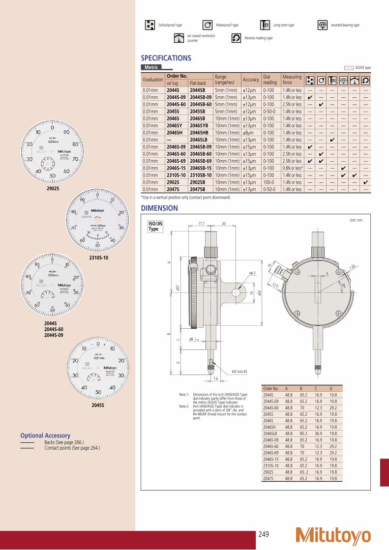
Dial IndicatorSERIES 2 — Standard Type, 0.01mm Resolution
(Refer to the page 9 for details.)
Series 2 dial indicators are Mitutoyo’s most popular, and have the widest application.
FEATURES• Standard 0.01mm graduation dial gauges
having an outer frame with an outside diameter of 57mm. All types come with limit pins and an outer frame clamp as standard.
• The outer clamp and lifting lever (optional) can be attached to either the right or left side. These parts can be easily installed and removed without tools.
• Secured adhesion between the outer frame and crystal as well as the use of an O-ring ensure countermeasures against water and oil permeation via the front face.
2046S-60
2046SY
2046S2046SH2046S-092046S-152046S-802046SLB
2046S-602046S-69
2047S
2046S
• The stem spindle is made of high-strength quench-hardened stainless steel which resists strenuous use.
• A carbide contact point is used.• The grand gear uses stainless steel that is
resistant to wear and deformation.• Application of a hard coating on the
surface of the crystal makes the gauge highly scratch- and chemical-resistant.
249
����
���������
��
���� ��
���
��
�
���
���
�
��
����
�����
���
�� ��������
SPECIFICATIONSMetric
GraduationOrder No. Range
(range/rev) Accuracy Dial reading
Measuring forcew/ lug Flat-back
0.01mm 2044S 2044SB 5mm (1mm) ±12µm 0-100 1.4N or less — — — — — —0.01mm 2044S-09 2044SB-09 5mm (1mm) ±13µm 0-100 1.4N or less ✔ — — — — —0.01mm 2044S-60 2044SB-60 5mm (1mm) ±12µm 0-100 2.5N or less — ✔ — — — —0.01mm 2045S 2045SB 5mm (1mm) ±12µm 0-50-0 1.4N or less — — — — — —0.01mm 2046S 2046SB 10mm (1mm) ±13µm 0-100 1.4N or less — — — — — —0.01mm 2046SY 2046SYB 10mm (1mm) ±13µm 0-100 1.4N or less — — — — — —0.01mm 2046SH 2046SHB 10mm (1mm) ±8µm 0-100 1.4N or less — — — — — —0.01mm — 2046SLB 10mm (1mm) ±13µm 0-100 1.4N or less — — ✔ — — —0.01mm 2046S-09 2046SB-09 10mm (1mm) ±15µm 0-100 1.4N or less ✔ — — — — —0.01mm 2046S-60 2046SB-60 10mm (1mm) ±13µm 0-100 2.5N or less — ✔ — — — —0.01mm 2046S-69 2046SB-69 10mm (1mm) ±15µm 0-100 2.5N or less ✔ ✔ — — — —0.01mm 2046S-15 2046SB-15 10mm (1mm) ±13µm 0-100 0.8N or less* — — — ✔ — —0.01mm 2310S-10 2310SB-10 10mm (1mm) ±15µm 0-100 1.4N or less — — — ✔ ✔ —0.01mm 2902S 2902SB 10mm (1mm) ±13µm 100-0 1.4N or less — — — — — ✔
0.01mm 2047S 2047SB 10mm (1mm) ±13µm 0-50-0 1.4N or less — — — — — —
*Use in a vertical position only (contact point downward).
Optional Accessory––––––: Backs (See page 266.)––––––: Contact points (See page 264.)
2310S-10
2902S
2044S 2044S-602044S-09
2045S
Order No. A B C D2044S 48.8 65.2 16.9 19.82044S-09 48.8 65.2 16.9 19.82044S-60 48.8 70 12.3 29.22045S 48.8 65.2 16.9 19.82046S 48.8 65.2 16.9 19.82046SH 48.8 65.2 16.9 19.82046SLB 48.8 85.2 36.9 19.82046S-09 48.8 65.2 16.9 19.82046S-60 48.8 70 12.3 29.22046S-69 48.8 70 12.3 29.22046S-15 48.8 65.2 16.9 19.82310S-10 48.8 65.2 16.9 19.82902S 48.8 65..2 16.9 19.82047S 48.8 65.2 16.9 19.8
DIMENSION Unit: mm
Note 1: Dimensions of the inch (ANSI/AGD Type) dial indicator partly differ from those of the metric (ISO/JIS Type) indicator.
Note 2: Inch (ANSI/AGD Type) dial indicator is provided with a stem of 3/8" dia. and #4-48UNF thread mount for the contact point.
ISO/JIS Type
��������������� ��������������������
��������������������
���������������� ��������������
�����������������������������
ISO/JIS type

250
Dial IndicatorSERIES 2 — Standard Type, 0.001mm Resolution
(Refer to the page 9 for details.)
2110S-10
2110S-102110S-70
2109S-102109SH-102109S-702109SLB-10
2113S-10
2119S-10
FEATURES• Standard 0.01mm graduation dial gauges
having an outer frame with an outside diameter of ø57mm. All types come with limit pins and an outer frame clamp.
• The outer clamp and lifting lever (optional) can be attached to either the right or left side. These parts can be easily installed and removed without tools.
• Secured adhesion between the outer frame and crystal as well as the use of an O-ring ensure countermeasures against water and oil permeation via the front face.
• The stem spindle is made of high-strength quench-hardened stainless steel which resists strenuous use.
• A carbide contact point is used.• The grand gear uses stainless steel that is
resistant to wear and deformation.• Application of a hard coating on the
surface of the crystal makes the gauge highly scratch- and chemical-resistant.
• A special alloy is used for the sector gears to provide improved wear resistance.
• The bearing part uses jeweled bearings, providing excellent indication sensitivity and durability.
2109S-10

251
����
���������
��
���� ��
���
��
�
���
���
�
��
����
�����
���
�� ��������
Optional Accessory––––––: Backs (See page 266.)––––––: Contact points (See page 264.)
2118S-10
2124S-10
2119S-10
Order No. A B C D2124S-10 48.8 60.3 16.9 14.92110S-10 48.8 66.5 16.9 21.12110S-70 48.8 67.5 12.3 26.72109S-10 48.8 60.5 16.9 15.12109SH-10 48.8 60.5 16.9 15.12109SLB-10 48.8 80.5 36.9 15.12109S-70 48.8 65.3 12.3 24.52113S-10 48.8 61 16.9 15.62118S-10 48.8 60.3 16.9 14.92119S-10 48.8 60.3 16.9 14.9
DIMENSION Unit: mm
Note 1: Dimensions of the inch (ANSI/AGD Type) dial indicator partly differ from those of the metric (ISO/JIS Type) indicator.
Note 2: Inch (ANSI/AGD Type) dial indicator is provided with a stem of 3/8" dia. and #4-48UNF thread mount for the contact point.
ISO/JIS Type
SPECIFICATIONSMetric
GraduationOrder No. Range
(range/rev) Accuracy Dial reading
Measuring forcew/ lug Flat-back
0.005mm 2124S-10 2124SB-10 5mm (0.5mm) ±12µm 0-50 1.5N or less — — — ✔ — —0.001mm 2110S-10 2110SB-10 1mm (0.1mm) ±5µm 0-100 1.5N or less ✔ — — ✔ ✔ —0.001mm 2110S-70 2110SB-70 1mm (0.1mm) ±5µm 0-100 2.0N or less ✔ ✔ — ✔ ✔ —0.001mm 2109S-10 2109SB-10 1mm (0.2mm) ±5µm 0-100-0 1.5N or less ✔ — — ✔ — —0.001mm 2109SH-10 2109SHB-10 1mm (0.2mm) ±3µm 0-100-0 1.5N or less ✔ — — ✔ — —0.001mm — 2109SLB-10 1mm (0.2mm) ±5µm 0-100-0 1.5N or less ✔ — ✔ ✔ — —0.001mm 2109S-70 2109SB-70 1mm (0.2mm) ±5µm 0-100-0 2.0N or less ✔ ✔ — ✔ — —0.001mm 2113S-10 2113SB-10 2mm (0.2mm) ±7µm 0-100-0 1.5N or less ✔ — — ✔ — —0.001mm 2118S-10 2118SB-10 5mm (0.2mm) ±10µm 0-100-100 1.5N or less — — — ✔ — —0.001mm 2119S-10 2119SB-10 5mm (0.2mm) ±10µm 0-100-0 1.5N or less — — — ✔ — —
��������������� ������������������������������������ ��������������
��������������������������
ISO/JIS type

252
Dial IndicatorSERIES 2 — Standard Type, Inch Reading
(Refer to the page 9 for details.)
Optional Accessory––––––: Backs (See page 266.)––––––: Contact points (See page 264.)
SPECIFICATIONSInch
GraduationOrder No. Range
(range/rev) Accuracy Dial reading
Measuring force — —
w/ lug Flat-back.001” 2780S 2780SB .125” (.05”) ±.001” 0-50 1.8N or less — — — — — —.001” 2781S 2781SB .125” (.05”) ±.001” 0-25-0 1.8N or less — — — — — —.001” 2410S 2410SB .25” (.1”) ±.001” 0-100 1.8N or less — — — — — —.001” 2410S-10 2410SB-10 .25” (.1”) ±.001” 0-100 1.8N or less — — — ✔ — —.001” 2410S-60 2410SB-60 .25” (.1”) ±.001” 0-100 2.5N or less — ✔ — — — —.001” 2411S 2411SB .25” (.1”) ±.001” 0-50-0 1.8N or less — — — — — —.001” 2411S-10 2411SB-10 .25” (.1”) ±.001” 0-50-0 1.8N or less — — — ✔ — —.001” 2414S 2414SB .5” (.1”) ±.001” 0-100 1.8N or less — — — — — —.001” 2414S-10 2414SB-10 .5” (.1”) ±.001” 0-100 1.8N or less — — — ✔ — —.001” 2414S-60 2414SB-60 .5” (.1”) ±.001” 0-100 2.5N or less — ✔ — — — —.001” 2415S 2415SB .5” (.1”) ±.001” 0-50-0 1.8N or less — — — — — —.001” 2415S-10 2415SB-10 .5” (.1”) ±.001” 0-50-0 1.8N or less — — — ✔ — —.001” 2415S-60 2415SB-60 .5” (.1”) ±.001” 0-50-0 2.5N or less — ✔ — — — —.001” 2914S 2914SB .5” (.1”) ±.001” 100-0 1.8N or less — — ✔ — — —.0005” 2506S 2506SB .125” (.05”) ±.0005” 0-50 1.8N or less — — — — — —.0005” 2507S 2507SB .125” (.05”) ±.0005” 0-25-0 1.8N or less — — — — — —.0005” 2514S 2514SB .5” (.05”) ±.0015” 0-50 1.8N or less — — — — — —.0005” 2514S-60 2514SB-60 .5” (.05”) ±.0015” 0-50 2.5N or less — ✔ — — — —.0005” 2570S-10 2570SB-10 .075” (.03”) ±.0005” 0-30 1.8N or less — — — ✔ — —.0005” 2571S-10 2571SB-10 .075” (.03”) ±.0005” 0-15-0 1.8N or less — — — ✔ — —.0005” 2576S-70 2576SB-70 .3” (.03”) ±.001” 0-30 2.5N or less — ✔ — ✔ — —.0005” 2670S 2670SB .1” (.04”) ±.0005” 0-40 1.8N or less — — — — — —.0005” 2671S 2671SB .1” (.04”) ±.0005” 0-20-0 1.8N or less — — — — — —.0005” 2675S 2675SB .4” (.04”) ±.0015” 0-20-0 1.8N or less — — — — — —.0005” 2922S 2922SB .125” (.05”) ±.0005” 0-25-0 1.8N or less — — — — — —.00025” 2470S-10 2470SB-10 .05” (.02”) ±.00025” 0-20 1.8N or less — — — ✔ — —.00025” 2471S-10 2471SB-10 .05” (.02”) ±.0005” 0-10-0 1.8N or less — — — ✔ — —.00025” 2476S-70 2476SB-70 .2” (.02”) ±.0005” 0-20 2.5N or less — ✔ — ✔ — —.0001” 2356S-10 2356SB-10 .25” (.01”) ±.0008” 0-10 2.0N or less — — — ✔ — —.0001” 2358S-10 2358SB-10 .5” (.01”) ±.0002” 0-10 2.0N or less — — — ✔ — —.0001” 2802S-10 2802SB-10 .025” (.01”) ±.0001” 0-10 2.0N or less ✔ — — ✔ — —.0001” 2802S-70 2802SB-70 .025” (.01”) ±.0001” 0-10 2.5N or less ✔ ✔ — ✔ — —.0001” 2803S-10 2803SB-10 .025” (.01”) ±.0001” 0-5-0 2.0N or less ✔ — — ✔ — —.0001” 2803S-70 2803SB-70 .025” (.01”) ±.0001” 0-5-0 2.5N or less ✔ ✔ — ✔ — —.0001” 2804S-10 2804SB-10 .05” (.01”) ±.0002” 0-10 2.0N or less ✔ — — ✔ — —.0001” 2805S-10 2805SB-10 .05” (.01”) ±.0002” 0-5-0 2.0N or less ✔ — — ✔ — —.0001” 2806S-10 2806SB-10 .1” (.01”) ±.0003” 0-10 2.0N or less ✔ — — ✔ — —.0001” 2806S-70 2806SB-70 .1” (.01”) ±.0003” 0-10 2.5N or less ✔ ✔ — ✔ — —.0001” 2905S-10 2905SB-10 .05” (.01”) ±.0002” 10-0 2.0N or less ✔ — ✔ ✔ — —.0001” 2923S-10 2923SB-10 .05” (.01”) ±.0002” 0-5-0 2.0N or less ✔ — — ✔ — —.0001” 2937S-10 2937SB-10 .02” (.008”) ±.0001” 0-4-0 2.0N or less ✔ — — ✔ — —.0001” 2938S-10 2938SB-10 .02” (.008”) ±.0001” 0-8 2.0N or less ✔ — — ✔ — —
��������������� ��������������������������������������������������������
�������������������������������������������������
ANSI/AGD type

253
ANSI/AGD type
����
��������� �������������
����
���
���
���
��
�������� �������� �����
����
���
��
����
����
���
����
���������
����
����
����
������
���
��
����
����
���
����
����
����������
����
����
�� ���������� ��
�������� ��������
Special Dial IndicatorSERIES 2
(Refer to the page 9 for details.)
Optional Accessory––––––: Backs (See page 266.)––––––: Contact points (See page 264.)
2048S-10 2046S-80 2940S
DIMENSION Unit: mm
Adjustable hand dial gaugeThe hand position can be adjusted independently of the vertical movement of the spindle by rotating the top knob.
Peak hold type dial gaugeA mechanism that stops the pointer and the spindle at the depressed position where the spindle is depressed makes the pointer stop and display the maximum value.
Double-face type dial gaugeThe displacement of the spindle can be read from either the front or rear face.
ISO/JIS Type
SPECIFICATIONSMetric
GraduationOrder No. Range
(range/rev) Accuracy Dial reading
Measuring force Measuring force
w/ lug Flat-back0.01mm 2048S-10 2048SB-10 10mm (1mm) ±15µm 0-100 1.4N or less Adjustable hand0.01mm 2048S-11 2048SB-11 10mm (1mm) ±13µm 0-100 1.4N or less Adjustable hand0.01mm 2046S-80 2046SB-80 10mm (1mm) ±15µm 0-100 5.0N or less Peak hold0.01mm 2940S — 10mm (1mm) ±15µm 0-100 3.0N or less Double-face
Double-face type
Inch
GraduationOrder No. Range
(range/rev) Accuracy Dial reading
Measuring force Remarks
w/ lug Flat-back.001” 2915S-10 2915SB-10 .5” (.1”) ±.001” 0-100 1.8N or less Jeweled bearing, adjustable hand.001” 2918S-10 2918SB-10 .5” (.1”) ±.001” 0-50-0 1.8N or less Jeweled bearing, adjustable hand
Adjustable hand Peak hold
ISO/JIS type ANSI/AGD type

254
Dial IndicatorSERIES 2 — Standard One Revolution Type for Error-free Reading
Unlike many other dial indicators, the one-revolution dial indicator literally shows the entire spindle travel or range as one sweep of the hand, eliminating the possibility of reading errors due to miscounting the mul-tiple revolutions. With one-revolution dial indicators, "within tolerance" and "out-of-tolerance" can never misinterpreted.FEATURES• An unique shock-proof mechanism is
incorporated, providing improved immunity to shock due to sudden spindle retraction caused by high impact.
• The crystal is hard coated for durability and scratch resistance.
• Approximately 40% lighter than the conventional dial indicator.
• Provided with an improved resistance to shop floor contaminants such as water and dust.
• Due to the spindle bushing being offset from the stem, spindle movement will not be hindered or jammed when clamping along the stem.
• A pair of limit hands are provided for quick and easy tolerance judgment (GO/±NG).
(Refer to the page 9 for details.)
2971 2972 2973
2929S 2900S-10 2990
2972
2971
2973
2928S

255
����
���������
��
� �
���
�
�
�
��
�
�� ��������
��������������� ������������������������������������ ��������������
Optional Accessory––––––: Backs (See page 266.)––––––: Contact points (See page 264.)
2959S
2929S2929S-602929S-62
2900S-102900S-702900S-72
2901S-10
Order No. A B C D E F G H I2971 43.2 65.6 55.6 16.2 — 21 16.8 55 7.62972 43.2 66.0 55.6 16.2 — 21 17.2 55 7.62973 43.2 66.3 55.6 16.2 — 21 17.5 55 7.62929S 48.8 65.2 57 17.7 20 12.3 29.2 52 7.62929S-62 48.8 65.2 57 17.7 20 16.9 19.8 52 7.62929S-60 48.8 70 57 17.7 20 12.3 29.2 52 7.62959S 48.8 65.2 57 17.7 20 16.9 19.8 52 7.62900S-10 48.8 66 57 17.7 20 16.9 20.6 52 7.62900S-72 48.8 66 57 17.7 20 16.9 20.6 52 7.62900S-70 48.8 67 57 17.7 20 12.3 26.2 52 7.62901S-10 48.8 66.1 57 17.7 20 16.9 20.7 52 7.62928S 48.8 65.2 57 17.7 20 16.9 19.8 52 7.6
DIMENSION Unit: mm
Note 1: Dimensions of the inch (ANSI/AGD Type) dial indicator partly differ from those of the metric (ISO/JIS Type) indicator.
Note 2: Inch (ANSI/AGD Type) dial indicator is provided with a stem of 3/8" dia. and #4-48UNF thread mount for the contact point.
ISO/JIS Type
SPECIFICATIONSMetric
GraduationOrder No. Range
(range/full stroke) Accuracy Dial reading
Measuring force —
w/ lug Flat-back0.1mm 2928S 2928SB 4mm / 10mm ±40µm 2-0-2 1.4N or less ✔ — — — —0.01mm 2929S 2929SB 0.8mm / 1mm ±9µm 40-0-40 1.4N or less ✔ — — — —0.01mm 2929S-60 2929SB-60 0.8mm / 1mm ±9µm 40-0-40 2.0N or less ✔ ✔ — — —0.01mm 2929S-62 2929SB-62 0.8mm / 1mm ±9µm 40-0-40 2.0N or less ✔ — ✔ — —0.01mm 2959S 2959SB 1.6mm / 2mm ±13µm 80-0-80 1.4N or less ✔ — — — —0.001mm 2900S-10 2900SB-10 0.08mm / 0.1mm ±3µm 40-0-40 1.4N or less ✔ — — ✔ —0.001mm 2900S-70 2900SB-70 0.08mm / 0.1mm ±3µm 40-0-40 2.0N or less ✔ ✔ — ✔ —0.001mm 2900S-72 2900SB-72 0.08mm / 0.1mm ±3µm 40-0-40 2.0N or less ✔ — ✔ ✔ —0.001mm 2901S-10 2901SB-10 0.16mm / 0.2mm ±4µm 80-0-80 1.4N or less ✔ — — ✔ —0.02mm — 2973 1.6mm / 2mm ±16µm 80-0-80 1.4N or less ✔ — ✔ — —0.01mm — 2971 0.5mm / 0.7.mm ±10µm 25-0-25 1.4N or less ✔ — ✔ — —0.01mm — 2972 1mm / 1.4mm ±12µm 50-0-50 1.4N or less ✔ — ✔ — —0.01mm 2990* — 0.1mm / 0.14mm ±6.5µm 50-0-50 1.5N or less ✔ — — ✔ —0.001mm — 2960F* 1mm / 1.27mm ±14µm 50-0-50 1.4N or less ✔ — — — —
*Back plunger type (see page 262.)
Inch
GraduationOrder No. Range
(range/full stroke) Accuracy Dial reading
Measuring force — —
w/ lug Flat-back.001” 2908S 2908SB .08” / .1” ±.001” 40-0-40 1.8N or less ✔ — — — —.001” 2908S-62 2908SB-62 .08” / .1” ±.001” 40-0-40 2.5N or less ✔ ✔ — — —.0005” 2909S-62 2909SB-62 .04” / .05” ±.0005” 20-0--20 2.5N or less ✔ ✔ — — —.0001” 2910S-10 2910SB-10 .008” / .01” ±.0001” 4-0-4 1.8N or less ✔ — ✔ — —.0001” 2910S-72 2910SB-72 .008” / .01” ±.0001” 4-0-4 2.5N or less ✔ ✔ ✔ — —.001” — 2978 .06” / .079” ±.001” 30-0-30 1.4N or less ✔ ✔ — — —.0005” — 2976 .02” / .028” ±.0005” 10-0-10 1.4N or less ✔ ✔ — — —.0005” — 2977 .04” / .055” ±.0005” 20-0-20 1.4N or less ✔ ✔ — — —.0001” — 2991* .008” / .01” ±.0002” 4-0-4 1.5N or less ✔ — ✔ — —
*Back plunger type (see page 262.)
ISO/JIS type
ANSI/AGD type
256
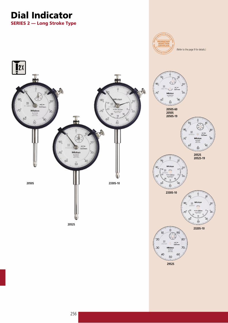
Dial IndicatorSERIES 2 — Long Stroke Type
(Refer to the page 9 for details.)
2050S
2052S
2330S-10
2052S2052S-19
2050S-602050S2050S-19
2330S-10
2320S-10
2952S

257
��������������� ��������������������
��������������������
����������������������������������������������
�����������������������������
����
���������
��
� �
���
�
��
��
�
�� ��������
Optional Accessory––––––: Backs (See page 266.)––––––: Contact points (See page 264.)
Order No. A B C D E F G H I2050S 38.8 75.2 57 17.7 20 16.9 29.8 52 7.62050S-60 59.8 87.2 57 17.7 20 12.3 46.4 52 7.62050S-19 38.8 75.2 57 17.7 20 16.9 29.8 52 7.62320S-10 38.8 75.2 57 17.7 20 16.9 29.8 52 7.62052S 38.8 88.7 57 17.7 20 16.9 43.3 52 7.62052S-19 38.8 88.7 57 17.7 20 16.9 43.3 52 7.62330S-10 38.8 88.7 57 17.7 20 16.9 43.3 52 7.62952S 38.8 88.7 57 17.7 20 16.9 43.3 52 7.6
DIMENSION Unit: mm
ISO/JIS Type
SPECIFICATIONSMetric
GraduationOrder No. Range
(range/rev) Accuracy Dial reading
Measuring forcew/ lug Flat-back
0.01mm 2050S 2050SB 20mm (1mm) ±20µm 0-100 2.0N or less — — ✔ — — —0.01mm 2050S-60 2050SB-60 20mm (1mm) ±20µm 0-100 2.5N or less — ✔ — — — —0.01mm 2050S-19 2050SB-19 20mm (1mm) ±20µm 0-100 2.0N or less ✔ — ✔ ✔ — —0.01mm 2320S-10 2320SB-10 20mm (1mm) ±20µm 0-100 2.0N or less — — ✔ ✔ ✔ —0.01mm 2052S 2052SB 30mm (1mm) ±25µm 0-100 2.5N or less — — ✔ — — —0.01mm 2052S-19 2052SB-19 30mm (1mm) ±25µm 0-100 2.5N or less ✔ — ✔ ✔ — —0.01mm 2330S-10 2330SB-10 30mm (1mm) ±25µm 0-100 2.5N or less — — ✔ ✔ ✔ —0.01mm 2952S 2952SB 30mm (1mm) ±25µm 100-0 2.5N or less — — ✔ — — ✔
Inch
GraduationOrder No. Range
(range/rev) Accuracy Dial reading
Measuring forcew/ lug Flat-back
.01” 2204S 2204SB 1” (1”) ±.005” 0-1000 1.8N or less — — — — — —
.001” 2416S 2416SB 1” (.1”) ±.001” 0-100 1.8N or less — — — — — —
.001” 2416S-06 2416SB-06 1” (.1”) ±.001” 0-100 1.8N or less — — — — — —
.001” 2416S-10 2416SB-10 1” (.1”) ±.001” 0-100 1.8N or less — — — ✔ — —
.001” 2416S-60 2416SB-60 1” (.1”) ±.001” 0-100 2.5N or less — ✔ — — — —
.001” 2417S 2417SB 1” (.1”) ±.001” 0-50-0 1.8N or less — — — — — —
.001” 2424S-19 2424SB-19 2” (.1”) ±.003” 0-100 2.5N or less ✔ — — ✔ — ✔
.0005” 2776S 2776SB 1” (.05”) ±.002” 0-50 1.8N or less — — — — — —
.0005” 2776S-60 2776SB-60 1” (.05”) ±.002” 0-50 2.5N or less — ✔ — — — —
.001” 2904S 2904SB 1” (.1”) ±.002” 100-0 2.0N or less — — ✔ — — —
ISO/JIS type
ANSI/AGD type

258
��
����
����
���
����
���
�
����
��
��
���������
��������������
�
��
��
����
���
�
���
��
�
�
�� ��������
�� ��������
���� ����
���������
�
��
��
����
���
�
���
��
�
� ���� ���� ���� ����
�� �������� Order No. A B C D
3046S 61.2 75.5 15.9 20.63047S 61.2 75.5 15.9 20.63050S 52.6 94 25.9 29.13052S-19 50.5 104.3 25.9 39.43058S-19 81.9 142.3 43.9 59.43060S-19 120.9 202.3 73.9 89.43062S-19 141.9 243.3 94.9 109.43109S-10 61.2 79.3 25.9 14.1
DIMENSION
Unit: mm
Note 1: Dimensions of the inch (ANSI/AGD Type) dial indicator partly differ from those of the metric (ISO/JIS Type) indicator.
Note 2: Inch (ANSI/AGD Type) dial indicator is provided with a stem of 3/8" dia. and #4-48UNF thread mount for the contact point.
Dial IndicatorSERIES 3, 4 — Large Dial Face and Long Stroke Type
(Refer to the page 9 for details.)
3109S-10 3058S-194046S
3047S
3046S
3050S
3052S-19
• Dial gauges with a large-diameter graduation face to ease reading.
• All types come with limit pins and an outer frame clamp as standard.
ISO/JIS Type

259
��
����
����
���
����
���
�
����
��
��
���������
��������������
�
��
��
����
���
�
���
��
�
�
�� ��������
�� ��������
���� ����
���������
�
��
��
����
���
�
���
��
�
� ���� ���� ���� ����
�� ��������
Optional Accessory––––––: Contact points (See page 262.)
3062S-19
3109S-10
4046S
3058S-19
3060S-19
SPECIFICATIONSMetric
GraduationOrder No. Range
(range/rev) Accuracy Dial reading
Measuring force — —
w/ lug Flat-back0.01mm 3046S 3046SB 10mm (1mm) ±15µm 0-100 1.4N or less — — — — — —0.01mm 3047S 3047SB 10mm (1mm) ±15µm 0-50-0 1.4N or less — — — — — —0.01mm 3050S 3050SB 20mm (1mm) ±20µm 0-100 2.0N or less — ✔ — — — —0.01mm 3052S-19 3052SB-19 30mm (1mm) ±25µm 0-100 2.5N or less ✔ — ✔ ✔ — —0.01mm 3052S-11 3052SB-11 30mm (1mm) ±30µm 0-100 2.5N or less — — ✔ ✔ — —0.01mm 3058S-19 3058SB-19 50mm (1mm) ±30µm 0-100 3.0N or less ✔ — ✔ ✔ — —0.01mm 3058S-11 3058SB-11 50mm (1mm) ±40µm 0-100 3.0N or less — — ✔ ✔ — —0.01mm 3060S-19* 3060SB-19* 80mm (1mm) ±45µm 0-100 3.0N or less ✔ — ✔ ✔ — —0.01mm 3062S-19* 3062SB-19* 100mm (1mm) ±50µm 0-100 3.2N or less ✔ — ✔ ✔ — —0.001mm 3109S-10 3109SB-10 1mm (0.2mm) ±6µm 0-100-0 1.5N or less ✔ — ✔ — — —0.01mm 4046S 4046SB 10mm (1mm) ±15µm 0-100 1.4N or less — — — — — —
*Use in a vertical position only.
Inch
GraduationOrder No. Range
(range/rev) Accuracy Dial reading
Measuring force — — —
w/ lug Flat-back.001” 3414S 3414SB .5” (.1”) ±.001” 0-100 1.8N or less — — — — — —.001” 3415S 3415SB .5” (.1”) ±.001” 0-50-0 1.8N or less — — — — — —.001” 3416S 3416SB 1” (.1”) ±.002” 0-100 1.8N or less — — — — — —.001” 3417S 3417SB 1” (.1”) ±.002” 0-50-0 1.8N or less — — — — — —.001” 3424S-19 3424SB-19 2” (.1”) ±.003” 0-100 3.0N or less ✔ ✔ ✔ — — —.001” 3426S-19 3426SB-19 3” (.1”) ±.005” 0-100 3.0N or less ✔ ✔ ✔ — — —.001” 3428S-19 3428SB-19 4” (.1”) ±.005” 0-100 3.2N or less ✔ ✔ ✔ — — —.0005” 3570S-10 3570SB-10 .075” (.03”) ±.0005” 0-30 1.8N or less — ✔ — — — —.0005” 3571S-10 3571SB-10 .075” (.03”) ±.0005” 0-15-0 1.8N or less — ✔ — — — —.0001” 3802S-10 3802SB-10 .025” (.01”) ±.0001” 0-10 2.0N or less ✔ ✔ — — — —.0001” 3803S-10 3803SB-10 .025” (.01”) ±.0001” 0-5-0 2.0N or less ✔ ✔ — — — —.001” 4410S 4410SB .25” (.1”) ±.001” 0-100 1.8N or less — — — — — —.001” 4887S-19 4887SB-19 3” (.1”) ±.005” 0-100 3.0N or less ✔ ✔ ✔ — — —.0005” 4570S-10 4570SB-10 .075” (.03”) ±.0005” 0-30 1.8N or less — ✔ — — — —.0001” 4802S-10 4802SB-10 .025” (.01”) ±.0001” 0-10 2.0N or less ✔ ✔ — — — —.0001” 4803S-10 4803SB-10 .025” (.01”) ±.0001” 0-5-0 2.0N or less ✔ ✔ — — — —
DIMENSION
Unit: mm
Note 1: Dimensions of the inch (ANSI/AGD Type) dial indicator partly differ from those of the metric (ISO/JIS Type) indicator.
Note 2: Inch (ANSI/AGD Type) dial indicator is provided with a stem of 3/8" dia. and #4-48UNF thread mount for the contact point.
ISO/JIS Type
����������������������������������������������
�������������������� �����������������������������
ISO/JIS type
ANSI/AGD type
ANSI/AGD type

260
ANSI/AGD Type Metric Dial Indicatorwith 3/8” DIA. Stem and #4-48UNF-Thread Contact Point Compatible Type
(Refer to the page 9 for details.)
SPECIFICATIONSMetric
GraduationOrder No. Range
(range/rev) Accuracy Dial reading
Measuring force —
w/ lug Flat-back0.01mm 1230S-01 1230SB-01 2.5mm (1mm) ±10µm 0-100 1.5N or less — — — — — —0.01mm 1231S-01 1231SB-01 2.5mm (1mm) ±10µm 0-50-0 1.5N or less — — — — — —0.01mm 1044S-01 1044SB-01 5mm (1mm) ±10µm 0-100 1.4N or less — — — — — —0.01mm 1045S-01 1045SB-01 5mm (1mm) ±10µm 0-50-0 1.4N or less — — — — — —0.002mm 1010S-11 1010SB-11 0.5mm (0.2mm) ±2µm 0-20 1.5N or less — ✔ — — — —0.002mm 1011S-11 1011SB-11 0.5mm (0.2mm) ±2µm 0-10-0 1.5N or less — ✔ — — — —
Metric
GraduationOrder No. Range
(range/rev) Accuracy Dial reading
Measuring forcew/ lug Flat-back
0.01mm 2230S-01 2230SB-01 2.5mm (1mm) ±10µm 0-100 1.4N or less — — — — — —0.01mm 2231S-01 2231SB-01 2.5mm (1mm) ±10µm 0-100 1.4N or less — — — — — —0.01mm 2231S-11 2231SB-11 2.5mm (1mm) ±10µm 0-50-0 1.4N or less — ✔ — — — —0.01mm 2046S-01 2046SB-01 10mm (1mm) ±13µm 0-100 1.4N or less — — — — — —0.01mm 2046S-11 2046SB-11 10mm (1mm) ±13µm 0-100 1.4N or less — ✔ — — — —0.01mm 2046S-61 2046SB-61 10mm (1mm) ±13µm 0-100 2.5N or less ✔ — — — — —0.01mm 2048S-11 2048SB-11 10mm (1mm) ±13µm 0-100 1.4N or less — ✔ ✔ ✔ — —0.01mm 2047S-01 2047SB-01 10mm (1mm) ±13µm 0-50-0 1.4N or less — — — — — —0.01mm 2047S-11 2047SB-11 10mm (1mm) ±13µm 0-50-0 1.4N or less — ✔ — — — —0.01mm 2902S-01 2902SB-01 10mm (1mm) ±13µm 100-0 1.4N or less — — — — — —0.01mm 2050S-01 2050SB-01 20mm (1mm) ±20µm 0-100 2.0N or less — — — — — —0.01mm 2050S-11 2050SB-11 20mm (1mm) ±20µm 0-100 2.0N or less — ✔ — — — —0.01mm 2056S-01 2056SB-01 25mm (1mm) ±25µm 0-100 2.5N or less — — — — — —0.002mm 2010S-11 2010SB-11 0.5mm (0.2mm) ±3µm 0-20 1.5N or less — ✔ — — ✔ —0.002mm 2010S-71 2010SB-71 0.5mm (0.2mm) ±3µm 0-20 2.5N or less ✔ ✔ — — — —0.002mm 2011S-11 2011SB-11 0.5mm (0.2mm) ±3µm 0-10-0 1.5N or less — ✔ — — ✔ —0.001mm 2900S-73* 2900SB-73* 0.08mm (0.1mm) ±2µm 40-0-40 1.4N or less — ✔ — — ✔ ✔
0.001mm 2109S-11 2109SB-11 1mm (0.2mm) ±4µm 0-10-0 1.5N or less — ✔ — — ✔ —0.001mm 2119S-11 2119SB-11 5mm (0.2mm) ±10µm 0-10-0 1.5N or less — ✔ — — — —
*One revolution type
Metric
GraduationOrder No. Range
(range/rev) Accuracy Dial reading
Measuring force — — —
w/ lug Flat-back0.01mm 3052S-11 3052SB-11 30mm (1mm) ±30µm 0-100 2.5N or less ✔ ✔ ✔ — — —0.01mm 3058S-11 3058SB-11 50mm (1mm) ±40µm 0-100 3.0N or less ✔ ✔ ✔ — — —
����������������
��������������� ��������������������
��������������
�������������������������������������������������
ANSI/AGD type
ANSI/AGD type
ANSI/AGD type
��������������������������
�����������������������������������
Series 1
Series 2
Series 3
261
�� �
���
����
���
�����
����
��
����
���������������������
��������������
�� ���������� ��
������
����
���������
�� �
����
���
���
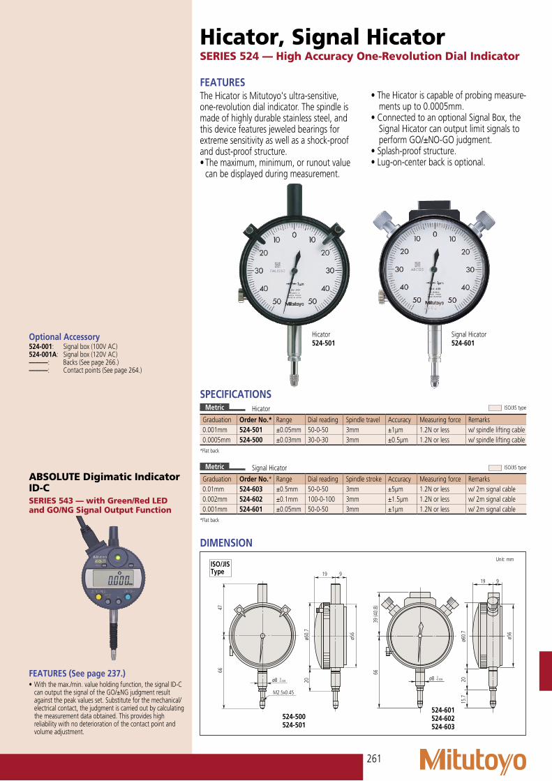
Hicator, Signal HicatorSERIES 524 — High Accuracy One-Revolution Dial Indicator
SPECIFICATIONSMetric
Graduation Order No.* Range Dial reading Spindle travel Accuracy Measuring force Remarks0.001mm 524-501 ±0.05mm 50-0-50 3mm ±1µm 1.2N or less w/ spindle lifting cable0.0005mm 524-500 ±0.03mm 30-0-30 3mm ±0.5µm 1.2N or less w/ spindle lifting cable
*Flat back
Optional Accessory524-001: Signal box (100V AC)524-001A: Signal box (120V AC)––––––: Backs (See page 266.)––––––: Contact points (See page 264.)
FEATURESThe Hicator is Mitutoyo's ultra-sensitive, one-revolution dial indicator. The spindle is made of highly durable stainless steel, and this device features jeweled bearings for extreme sensitivity as well as a shock-proof and dust-proof structure.• The maximum, minimum, or runout value
can be displayed during measurement.
• The Hicator is capable of probing measure-ments up to 0.0005mm.
• Connected to an optional Signal Box, the Signal Hicator can output limit signals to perform GO/±NO-GO judgment.
• Splash-proof structure.• Lug-on-center back is optional.
Hicator524-501
Signal Hicator524-601
Metric
Graduation Order No.* Range Dial reading Spindle stroke Accuracy Measuring force Remarks0.01mm 524-603 ±0.5mm 50-0-50 3mm ±5µm 1.2N or less w/ 2m signal cable0.002mm 524-602 ±0.1mm 100-0-100 3mm ±1.5µm 1.2N or less w/ 2m signal cable0.001mm 524-601 ±0.05mm 50-0-50 3mm ±1µm 1.2N or less w/ 2m signal cable
*Flat back
ABSOLUTE Digimatic Indicator ID-CSERIES 543 — with Green/Red LED and GO/NG Signal Output Function
FEATURES (See page 237.)• With the max./min. value holding function, the signal ID-C
can output the signal of the GO/±NG judgment result against the peak values set. Substitute for the mechanical/electrical contact, the judgment is carried out by calculating the measurement data obtained. This provides high reliability with no deterioration of the contact point and volume adjustment.
DIMENSION Unit: mm
ISO/JIS Type
ISO/JIS type
ISO/JIS typeHicator
Signal Hicator

262
Back Plunger Type Dial IndicatorSERIES 1 and 2
1160 1960 1180-6
Mitutoyo's back plunger type dial indicators are built with the measuring spindles on the back of the units. This type of indicator offers the same precision and durability as all other Mitutoyo dial indicators, and operates very effectively with optional holding bars.
2960F2990
Holding bar (optional)
(Refer to the page 9 for details.)
• Back plunger type dial gauges are suitable for mounting onto leveling machine tool tables or inspection jigs, and for use in small spaces where the graduations of standard dial gauges are difficult to see.
• Model No. 1960, which uses Mitutoyo's proprietary shock-proofing mechanism, has excellent durability and shock resistance.
• Model No. 2990 is back plunger type and allows 0.001mm readings.

263
��
�
��
�
��
��
�
���
������������
������������
����������������������
���������
�� ��������
���������
��
��
�
�����
����������������������
�
���
�����
����
����
��
���������
���������
�� ��������
�� ��������
��
���
����
����
��
��
���
��
�
���������
����������������������
Optional Accessory136567: Holding bar (ø6mm, L=81mm)21AAA166: Holding bar (ø6mm, L=42mm)136568: Holding bar (ø8mm, L=81mm)21AAA168: Holding bar (ø8mm, L=42mm)124625: Holding bar (.25” DIA, L=3.19”)21AAA167: Holding bar (.25” DIA, L=1.65”)––––––: Backs (See page 266.)––––––: Contact points (See page 264.)
Order No. A B C E F G H1160 39 21.5 35 22 25 13.8 43.31162 39 21.5 35 22 25 13.8 43.31180-6 39 21.5 35 22 9.5 13.8 27.81180-8 39 21.5 35 22 9.5 13.8 27.81960 39 21.5 35 22 28.7 12.8 46
DIMENSION
Unit: mm
Note 1: Dimensions of the inch (ANSI/AGD Type) dial indicator partly differ from those of the metric (ISO/JIS Type) indicator.
Note 2: Inch (ANSI/AGD Type) dial indicator is provided with a stem of 3/8" dia. and #4-48UNF thread mount for the contact point.
ISO/JIS Type
ISO/JIS Type
SPECIFICATIONSMetric
Graduation Order No. Range (range/rev) Accuracy Dial
readingMeasuring force — — —
0.01mm 1960 1mm / 1.27mm* ±14µm 50-0-50 1.4N or less ✔ ✔ — — — —0.01mm 1160 5mm (1mm) ±16µm 0-100 1.4N or less — — — — — —0.01mm 1162 5mm (1mm) ±16µm 100-0 1.4N or less — — ✔ — — —0.01mm 1180-6 5mm (1mm) ±16µm 0-100 1.5N or less — — — — — —0.01mm 1180-7 5mm (1mm) ±16µm 0-100 1.5N or less — — — — — —0.01mm 1180-8 5mm (1mm) ±16µm 0-100 1.5N or less — — — — — —
Inch
Graduation Order No. Range (range/rev) Accuracy Dial
readingMeasuring force — — —
.001” 1961 .04” / .05”* ±.001” 20-0-20 1.4N or less ✔ ✔ — — — —
.001” 1156 .1” (.1”) ±.001” 0-100 2.1N or less — — — — — —
.001” 1157 .1” (.1”) ±.001” 0-50-0 2.1N or less — — — — — —
.001” 1166 .2” (.05”) ±.001” 0-50 1.4N or less — — — — — —
.001” 1167 .2” (.05”) ±.001” 0-25-0 1.4N or less — — — — — —
.001” 1168 .2” (.05”) ±.001” 50-0 1.4N or less — — ✔ — — —*Full stroke
Metric
Graduation Order No. Range (range/full stroke) Accuracy Dial
readingMeasuring force — — —
0.01mm 2960F 1mm / 1.27” ±14µm 50-0-50 1.4N or less ✔ ✔ — — — —0.001mm 2990 0.1mm / 0.14” ±6.5µm 50-0-50 1.5N or less ✔ ✔ ✔ — — —
Inch
Graduation Order No. Range (range/full stroke) Accuracy Dial
readingMeasuring force — — —
.0005” 2961 .04” / .05” ±.0005” 20-0-20 1.8N or less ✔ ✔ — — — —
.0001” 2991 .008” / .01” ±.0002” 4-0-4 1.5N or less ✔ ✔ ✔ — — —
������������������� ���������������� ��������������������
ISO/JIS type
ANSI/AGD type
ISO/JIS type
ANSI/AGD type
Series 1
Series 1
Series 2
Series 2

264
�
�����������
���
�
���
��
����
�
����
�
����
��
������������
�
��
�
�
��
�
��
��
�
�
�
���
��
���
����
�
��
���
�
�
�����������
��
��������������������
��������
��������
��������
��������
��������
����������������
��������
��������
��������
��������
�������������
�������������
��������
�
�
���� ��
�
����
�������� �
�
�������������������������������������������������
�
�
��
���
��� ���
�
Contact PointOptional Accessory for Digimatic and Dial Indicators and Linear Gages
SPECIFICATIONS
Ball Points
L Material Order No. A7.3 Carbide 901312 M2.5x0.456.35 901454 #4-48UNF7.3 Plastic 901994 M2.5x0.456.35 902018 #4-48UNF7.3 Ruby 120047 M2.5x0.458.3 Carbide 21AZA319 M2.5x0.458.3* Carbide 902119 M2.5x0.4512.1* Carbide 21AZA320 M2.5x0.4514 Carbide 21JAA225 M2.5x0.4515 Carbide 120049 M2.5x0.45
Ruby 120051 M2.5x0.4517 Carbide 21JAA224 M2.5x0.4519.3* Carbide 21AZA321 M2.5x0.4520 Carbide 137391 M2.5x0.45
Ruby 137392 M2.5x0.4522 Carbide 21JAA226 M2.5x0.4525 Carbide 120053 M2.5x0.45
Ruby 120055 M2.5x0.4530 Carbide 21AAA252 M2.5x0.45
Ruby 21AAA253 M2.5x0.45*For waterproof dial indicators
Shell Type Points
L Order No. A3.97 101184 #4-48UNF5 101386 M2.5x0.4510 101118 M2.5x0.4512.7 101185 #4-48UNF15 137393 M2.5x0.4519.05 101186 #4-48UNF20 101387 M2.5x0.4525 101388 M2.5x0.4525.4 101187 #4-48UNF30 21AAA254 M2.5x0.45
Ball Point
SøD ød Order No. A1mm, carbide 5mm 21AAA349 M2.5x0.451.5mm, carbide 5mm 21AAA350 M2.5x0.451.8mm, steel 5mm 101122 M2.5x0.452.5mm, carbide 5mm 21AAA351 M2.5x0.454mm, carbide 5mm 21AAA352 M2.5x0.454mm, carbide 5mm 900032 #4-48UNF
Spherical Points
D L SR Order No. A10 5 7 101119 M2.5x0.4512.7 3.18 7 101205 #4-48UNF9.53 2.38 9 101204 #4-48UNF
D L SR Order No. A5.2 5 5 120058 M2.5x0.457.5 10 7 120059 M2.5x0.4510.5 10 10 120060 M2.5x0.45
Spherical Points (Carbide)
Conical Points
Tip angle L Order No. A60° 10 101120 M2.5x0.4560° 12.7 101190 #4-48UNF
Conical Points (Carbide)
Order No. A120057 M2.5x0.45
Order No. A120068 M2.5x0.45
Knife Edge Point (Carbide)
Order No. A120067 M2.5x0.45
Flat Points
D L Order No. A10 10 101117 M2.5x0.4515 10 21AAA341 M2.5x0.4520 10 21AAA342 M2.5x0.4525 10 21AAA343 M2.5x0.4520 10 21AAA344 M2.5x0.4512.7 9.53 101188 #4-48UNF9.53 9.53 101189 #4-48UNF
Tip angle L Order No. A90° 5 101385 M2.5x0.4590° 7.14 101191 #4-48UNF
L Order No. A8 131365 M2.5x0.4510 21AAA340 M2.5x0.458 133017 #4-48UNF

265
�
�������������
��
�
��������
�
����
��� �
�
��
����
�
�
�����������
��
�
�
� �
��
�
��
���
��
�
� �
����
�
���
��
��
�
�
���
���������
��������
��
����
��
�
��
��������
��������
��������
��������
��������
��������
Flat Points (Carbide)
Order No. A120056 M2.5x0.45
D d L Order No. A5.2 4.3* 5 120041 M2.5x0.457 6.5* 10 120042 M2.5x0.4510.5 9.5* 10 120043 M2.5x0.4517 15** 10 21AAA345 M2.5x0.4522 20** 10 21AAA346 M2.5x0.4527 25** 10 21AAA347 M2.5x0.4532 30** 10 21AAA348 M2.5x0.45
Flatness: *3µm, **5µm
D d L Order No. A7 6.4 10 137255 M2.5x0.459 8 10 137399 M2.5x0.45
Lever Points
Order No. A900391 M2.5x0.45900393 #4-48UNF
Order No. A901954 M2.5x0.45901991 #4-48UNF
Roller Points Lever Points
N L SR Order No. A11 15 0.4 101121 M2.5x0.4513 17 0.2 137413 M2.5x0.4521 25 0.4 21AAA255 M2.5x0.4531 35 0.4 21AAA256 M2.5x0.45
Needle Points (Carbide)
Blade Points (Carbide)
T W Order No. A0.4 2 120061 M2.5x0.450.6 2 120062 M2.5x0.451 4 120063 M2.5x0.45
Extension Rods
L Order No. A10 303611 M2.5x0.4515 21AAA259A M2.5x0.4520 303612 M2.5x0.4525 21AAA259B M2.5x0.4530 303613 M2.5x0.4535 21AAA259C M2.5x0.4540 21AAA259D M2.5x0.4545 21AAA259E M2.5x0.4550 21AAA259F M2.5x0.4555 21AAA259G M2.5x0.4560 304146 M2.5x0.4565 21AAA259H M2.5x0.4570 21AAA259J M2.5x0.4575 21AAA259L M2.5x0.4580 21AAA259M M2.5x0.4590 304147 M2.5x0.45100 303614 M2.5x0.451" 301655 #4-48UNF2" 301657 #4-48UNF4" 301659 #4-48UNF
Interchangeable Contact Point Set (M2.5x0.45)
Order No. Components7822 Flat Point (131365, ø5mm)
Flat Point (101117, ø10mm)Needle Point (101121)Spherical Point (101119)Shell Type Point (101118)Shell Type Point (101387)
D L Order No. A0.45 3 120066 M2.5x0.450.45 5 21AAA329 M2.5x0.451 3 120065 M2.5x0.451 5 21AAA330 M2.5x0.451 8 21AAA331 M2.5x0.451 10 21AAA332 M2.5x0.451 20 21AAA333 M2.5x0.451 40 21AAA334 M2.5x0.451.5 5 21AAA335 M2.5x0.451.5 10 21AAA336 M2.5x0.451.5 13 120064 M2.5x0.451.5 20 21AAA337 M2.5x0.451.5 40 21AAA338 M2.5x0.452 8 137257 M2.5x0.452 18 21AAA257 M2.5x0.452 28 21AAA258 M2.5x0.452 40 21AAA339 M2.5x0.45

266
Application
BackOptional Accessory for Digimatic and Dial Indicators
There are two ways to support Digimatic and dial indicators; by either holding the stem or the lug on the back of the indica-tor. The back of the indicator may need to be replaced for special applications. A wide variety of backs are available for Mitutoyo Digimatic and dial indicators.
SPECIFICATIONSDescription Order No.
Series 1 (ø41mm)
Series 2(ø57mm)
Series 3, 4(ø77, 91mm)
Flat Back 101211: a=2.2136872: for water-
proof type191559: for 1911,
1913-10137906: for 1003
101039: a=2.521AZB231: for
water-proof of S type
100836: a=3.0
Lug-on-Center Back 101210: metric type
101307: inch type190561: for 1911,
1913-10137905: for 1003
101040: metric type
101306: inch type21AZB230: for
water-proof of S type
100691: metric type
100797: inch type
Magnetic Back Special order 900928 900929
Back with Offset Lug Special order 101167 100837
Back with Post 193172 Order-to-made
101169 100839
Back with Screw Mount 193173: M6x1, Order-to-made
193174: #1/4-28UNF, Order-to-made
136023: M6x1193174:
#1/4-28UNF
136024: M6x1100840:
#1/4-28UNF
Adjustable Back 136025: M6x1129721:
#1/4-28UNF
136026: M6x1101168:
#1/4-28UNF)
136027: M6x1100838:
#1/4-28UNF
Back with Dovetail — 900008 Special order
Back with Adjustable Bracket
— 901963 —
�
���
�
����
�
�����
����
��
����
���
��
����
�������
��������
����
�
����
���������
��
���� ��
��
��
������
���
��� ���
����
��
������
���
��� ���
�
��������
��������
��������
��������
��������
��������
��������
��������
��������
���
���
��
���
�������
���

267
�����������
��������������������
�������
Spindle Lifting Lever and CableOptional Accessory for Digimatic and Dial Indicators
Spindle Lifting Lever• The Spindle Lifting Lever is attached to
the top end of the spindle for improved inspection efficiency when using a dial indicator mounted on a stand.
Spindle Lifting Cable
Application
Application
21BZA205Use for F type Series 1 dial indicators.
902011Use for F type Series 2 dial indicators (up to 10mm/.4” range).
902100Use for S type Series 1 and F type Series 2 (up to 10mm/.4” range) dial indicators.
903424Use for F type Series 2 dial indicators (up to 20mm/.8” range) and Series 3 and 4 dial indicators (up to 10mm/.4” range).
21AZB149Use for S type Series 2, 3, and 4 dial indicators (up to 10mm/.4”).
21AZB150Use for S type Series 2 and 3 dial indicators (from 10mm/.4” up to 20mm/.8”).
900527: Lever101171: Screw
903307: Lever192686: Screw
901975: with auto-stop function540774: without auto-stop functionLifting range: 10mmCable length: 300mm
Spindle Lifting Knob137693Applicable spindle diameter; 4.8mm
268
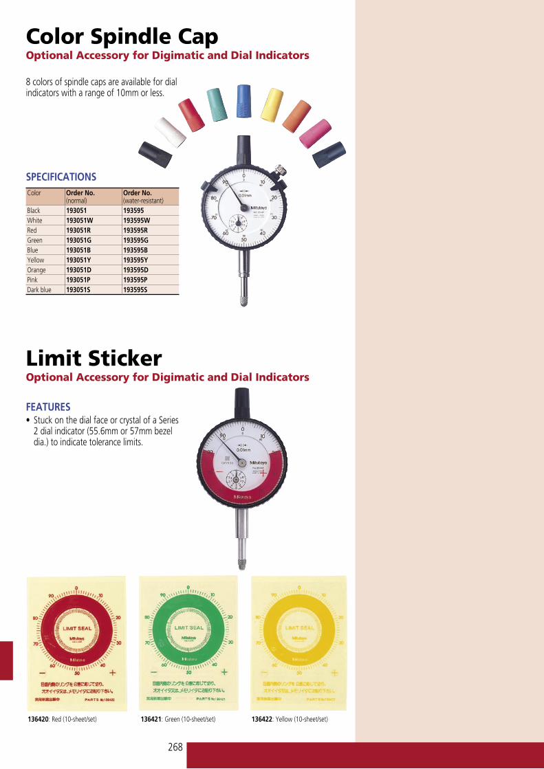
Color Spindle CapOptional Accessory for Digimatic and Dial Indicators
Limit StickerOptional Accessory for Digimatic and Dial Indicators
136420: Red (10-sheet/set) 136421: Green (10-sheet/set) 136422: Yellow (10-sheet/set)
FEATURES• Stuck on the dial face or crystal of a Series
2 dial indicator (55.6mm or 57mm bezel dia.) to indicate tolerance limits.
8 colors of spindle caps are available for dial indicators with a range of 10mm or less.
SPECIFICATIONSColor Order No.
(normal)Order No. (water-resistant)
Black 193051 193595White 193051W 193595WRed 193051R 193595RGreen 193051G 193595GBlue 193051B 193595BYellow 193051Y 193595YOrange 193051D 193595DPink 193051P 193595PDark blue 193051S 193595S

269
Dial Indicator Repair Tool KitOptional Accessory for Digimatic and Dial Indicators
Dial Indicator Crystal SetterOptional Accessory for Digimatic and Dial Indicators
Set Configuration901171: Molykote (lubricant)901172: Lubricating oil901173: Screwdriver (Phillips)901174: Screwdriver (Phillips/flat blade)129729: Tweezers901175: Pin-vise901176: Brush901177: Brush901177: Brush901178: Hammer129730: Spindle rest129731: Pin rest901179: Nippers901180: Pliers901181: Hand remover129732: Pin remover129733: Punch 129734: Bearing adjuster129735: Pinion rest129736: Reamer ø1193702: Reamer ø0.6901182: Case
Mitutoyo offers a tool set designed to let you perform simple repairs to your Mitutoyo dial indicator, and a device that lets you reset the indicator crystals.
FEATURES• Used for fitting a crystal on dial indicators,
dial test indicators, and dial calipers.
7000
7823
With 8 sizes of crystal setting pads