Diagnostics Guide.pdf
286
Diagnostics Guide The sections in this guide provide the following information: Overview of the Diagnostics Guide gives a high-level overview of what diagnostics are available for your NetApp ® storage systems and gives some examples of when to run them. Running Diagnostics describes the Diagnostic Monitor and how to run diagnostics on your system. Diagnostics Menus lists and defines the menu options of the Diagnostic Monitor's individual diagnostic tests. Error Messages defines the coding conventions used, lists and defines the error messages generated by the diagnostic tests, and recommends the corrective action to address errors you encounter. Environmental Error Messages lists and defines the environmental error messages generated when you run the environmental status test in the miscellaneous motherboard test menu. The error messages are listed according to the platform in which the motherboard and any related daughterboard resides and are described according to the type of sensor that is reporting the error condition. This section also recommends the corrective action to address errors you encounter. Part Number: 215-06426_A0 ur002 Last updated: December 10, 2012
-
Upload
veracespedes -
Category
Documents
-
view
166 -
download
4
description
diag
Transcript of Diagnostics Guide.pdf
Diagnostics Guide
The sections in this guide provide the following information:
Overview of the Diagnostics Guide gives a high-level overview of what diagnostics are available for yourNetApp® storage systems and gives some examples of when to run them.
Running Diagnostics describes the Diagnostic Monitor and how to run diagnostics on your system.
Diagnostics Menus lists and defines the menu options of the Diagnostic Monitor's individual diagnostic tests.
Error Messages defines the coding conventions used, lists and defines the error messages generated by thediagnostic tests, and recommends the corrective action to address errors you encounter.
Environmental Error Messages lists and defines the environmental error messages generated when you run theenvironmental status test in the miscellaneous motherboard test menu. The error messages are listed according tothe platform in which the motherboard and any related daughterboard resides and are described according to thetype of sensor that is reporting the error condition. This section also recommends the corrective action to addresserrors you encounter.
Part Number: 215-06426_A0 ur002Last updated: December 10, 2012
Legal InformationThis section describes the following topics:
Copyright
Trademarks
Support note
Communications regulations
[ Up ] [ Trademarks ] [ Copyright ] [ Support note ] [ Communications regulations ]
CopyrightCopyright © 1994-2012 NetApp, Inc. All rights reserved. Printed in the U.S.A.
No part of this document covered by copyright may be reproduced in any form or by any means— graphic, electronic,or mechanical, including photocopying, recording, taping, or storage in an electronic retrieval system—without priorwritten permission of the copyright owner.
Software derived from copyrighted NetApp material is subject to the following license and disclaimer:
THIS SOFTWARE IS PROVIDED BY NETAPP “AS IS” AND WITHOUT ANY EXPRESS OR IMPLIEDWARRANTIES, INCLUDING, BUT NOT LIMITED TO, THE IMPLIED WARRANTIES OFMERCHANTABILITY AND FITNESS FOR A PARTICULAR PURPOSE, WHICH ARE HEREBY DISCLAIMED.IN NO EVENT SHALL NETAPP BE LIABLE FOR ANY DIRECT, INDIRECT, INCIDENTAL, SPECIAL,EXEMPLARY, OR CONSEQUENTIAL DAMAGES (INCLUDING, BUT NOT LIMITED TO, PROCUREMENTOF SUBSTITUTE GOODS OR SERVICES; LOSS OF USE, DATA, OR PROFITS; OR BUSINESSINTERRUPTION) HOWEVER CAUSED AND ON ANY THEORY OF LIABILITY, WHETHER IN CONTRACT,STRICT LIABILITY, OR TORT (INCLUDING NEGLIGENCE OR OTHERWISE) ARISING IN ANY WAY OUTOF THE USE OF THIS SOFTWARE, EVEN IF ADVISED OF THE POSSIBILITY OF SUCH DAMAGE.
NetApp reserves the right to change any products described herein at any time, and without notice. NetApp assumesno responsibility or liability arising from the use of products described herein, except as expressly agreed to in writingby NetApp. The use or purchase of this product does not convey a license under any patent rights, trademark rights, orany other intellectual property rights of NetApp.
The product described in this manual may be protected by one or more U.S.A. patents, foreign patents, or pendingapplications.
RESTRICTED RIGHTS LEGEND: Use, duplication, or disclosure by the government is subject to restrictions as setforth in subparagraph (c)(1)(ii) of the Rights in Technical Data and Computer Software clause at DFARS 252.277-7103 (October 1988) and FAR 52-227-19 (June 1987).
[ Up ] [ Trademarks ] [ Copyright ] [ Support note ] [ Communications regulations ]
TrademarksNetApp, the NetApp logo, Network Appliance, the Network Appliance logo, Akorri, ApplianceWatch, ASUP,AutoSupport, BalancePoint, BalancePoint Predictor, Bycast, Campaign Express, ComplianceClock, Cryptainer,CryptoShred, Data ONTAP, DataFabric, DataFort, Decru, Decru DataFort, DenseStak, Engenio, Engenio logo, E-Stack, FAServer, FastStak, FilerView, FlexCache, FlexClone, FlexPod, FlexScale, FlexShare, FlexSuite, FlexVol,FPolicy, GetSuccessful, gFiler, Go further, faster, Imagine Virtually Anything, Lifetime Key Management, LockVault,Manage ONTAP, MetroCluster, MultiStore, NearStore, NetCache, NOW (NetApp on the Web), Onaro, OnCommand,ONTAPI, OpenKey, PerformanceStak, RAID-DP, ReplicatorX, SANscreen, SANshare, SANtricity, SecureAdmin,SecureShare, Select, Service Builder, Shadow Tape, Simplicity, Simulate ONTAP, SnapCopy, SnapDirector,SnapDrive, SnapFilter, SnapLock, SnapManager, SnapMigrator, SnapMirror, SnapMover, SnapProtect, SnapRestore,Snapshot, SnapSuite, SnapValidator, SnapVault, StorageGRID, StoreVault, the StoreVault logo, SyncMirror, TechOnTap, The evolution of storage, Topio, vFiler, VFM, Virtual File Manager, VPolicy, WAFL, Web Filer, and XBBare trademarks or registered trademarks of NetApp, Inc. in the United States, other countries, or both.
IBM, the IBM logo, and ibm.com are trademarks or registered trademarks of International Business MachinesCorporation in the United States, other countries, or both. A complete and current list of other IBM trademarks isavailable on the Web at www.ibm.com/legal/copytrade.shtml.
Apple is a registered trademark and QuickTime is a trademark of Apple, Inc. in theUnited States and/or othercountries. Microsoft is a registered trademark and Windows Media is a trademark of Microsoft Corporation intheUnited States and/or other countries. RealAudio, RealNetworks, RealPlayer, RealSystem, RealText, and RealVideoare registered trademarks and RealMedia, RealProxy, and SureStream are trademarks of RealNetworks, Inc. intheUnited States and/or other countries.
All other brands or products are trademarks or registered trademarks of their respective holders and should be treatedas such.
NetApp, Inc. is a licensee of the CompactFlash and CF Logo trademarks. NetApp, Inc. NetCache is certifiedRealSystem compatible.

[ Up ] [ Trademarks ] [ Copyright ] [ Support note ] [ Communications regulations ]
Support noteMicrosoft has not established a commitment to support SnapManager for Exchange and storage systems used in anExchange configuration. There can be no assurance that Microsoft will provide support for this usage. NetAppsupports SnapManager for Exchange and NetApp storage systems used in an Exchange environment and has investedresources in third-party programs to provide the highest quality support possible to our customers.
[ Up ] [ Trademarks ] [ Copyright ] [ Support note ] [ Communications regulations ]
Communications regulationsFCC notices (U.S. only)
NetApp devices are designed for a CFR 47 (Code Federal Regulations) Part 15 Class A environment.
The FCC and NetApp guarantee the user’s rights to operate this equipment only if the user complies with thefollowing rules and regulations:
Install and operate this equipment in accordance with the specifications and instructions in this guide.Modify this equipment only in the ways specified by NetApp.Use shielded cables with metallic RFI/EMI connector hoods to maintain compliance with applicable emissionsstandards.If the system has nine or more Fibre Channel disk shelves, install the system in two or three NetApp SystemCabinets to maintain performance within Part 15 of CFR 47 regulations.
Compliance with Part 15 of CFR 47
This equipment has been tested and found compliant with Part 15 of the CFR 47 rules for Class A digital devices.These rules are designed to provide reasonable protection from interference to electronics equipment operated in acommercial environment.
Operation of this device is subject to the following two conditions:
This device cannot cause harmful interference.This device must accept any interference received, including interference that may cause undesired operation.
Compliance with ICES-003
This Class A digital apparatus complies with Canadian ICES-003.
Cet appareil numérique de la classe A conforme à la norme NMB-003 du Canada.
Compliance with EN regulations
Marking by the symbol indicates compliance of this NetApp device to the EMC Directive and the Low VoltageDirective of the European Union. Such marking is indicative that this NetApp device meets technical standards.
This is a Class A product. In a domestic environment this product may cause radio interference, in which case the usermay be required to take adequate measures.
Bureau of Standards, Metrology, and Inspections notice (BSMI, Taiwan only)
Translation of the BSMI notice:
Warning: This is a Class A product. In a domestic environment this product may cause radio interference, inwhich case the user may be required to take adequate measures.
Voluntary Control Council for Interference by Information Technology Equipment (VCCI,Japan)
Translation of the VCCI-A notice:
This is a Class A product based on the standard of the Voluntary Control Council for Interference byInformation Technology Equipment (VCCI). If this equipment is used in a domestic environment, radiodisturbance may arise. If such trouble occurs, the user may be required to take corrective actions.
Contact InformationNetApp, Inc.495 East Java DriveSunnyvale, CA 94089Telephone: +1 (408) 822-6000Fax: +1 (408) 822-4501Support telephone: +1 (888) 4-NETAPP
Documentation comments: [email protected]
Information Web: http://www.netapp.com
PrefaceAbout this guide
This document describes how to boot and operate the diagnostics available for NetApp™ storage systems.
Audience
This guide is for qualified system administrators and service personnel who are familiar with NetApp storage systems.The procedures in this guide describe replacement, upgrade, and maintenance tasks for personnel with the followingskills and experience:
Working familiarity with small computer system hardware and operationBasic understanding of common networking concepts and practicesWorking familiarity with accepted tools and procedures for installing and operating sensitive electronicequipment
Command conventions
You can enter storage system commands on the system console or from any client that can obtain access to the storagesystem using Telnet. This guide uses the command syntax and output of SunOS 4.1x in examples of commands run ona UNIX workstation. If you use a different version of UNIX, the command syntax and output might be different.
Formatting conventions
The following table lists different character formats used in this guide to offset special information:
Formatting convention Type of information
Italic type Words or characters that require special attention.Placeholders for information you must supply. For example, if theguide requires you to enter the fctest adaptername command, youenter the characters "fctest" followed by the actual name of theadapter.Man page names.Book titles in cross-references.
Monospaced font Command and daemon names.Information displayed on the system console or other computermonitors.Contents of files.
Bold monospaced font Words or characters you type. What you type is always shown in lowercaseletters, unless your program is case-sensitive and uppercase letters arenecessary for it to work properly.
Keyboard conventions
This guide uses capitalization and some abbreviations to refer to the keys on the keyboard. The keys on your keyboard
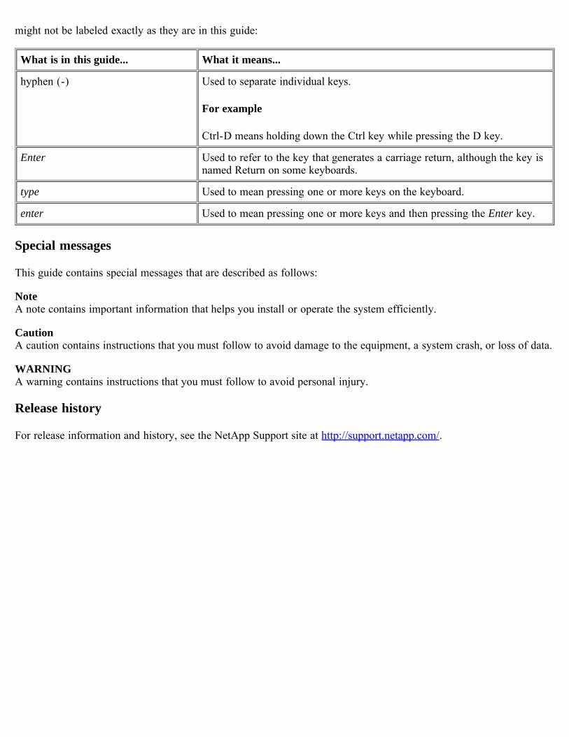
might not be labeled exactly as they are in this guide:
What is in this guide... What it means...
hyphen (-) Used to separate individual keys.
For example
Ctrl-D means holding down the Ctrl key while pressing the D key.
Enter Used to refer to the key that generates a carriage return, although the key isnamed Return on some keyboards.
type Used to mean pressing one or more keys on the keyboard.
enter Used to mean pressing one or more keys and then pressing the Enter key.
Special messages
This guide contains special messages that are described as follows:
NoteA note contains important information that helps you install or operate the system efficiently.
CautionA caution contains instructions that you must follow to avoid damage to the equipment, a system crash, or loss of data.
WARNINGA warning contains instructions that you must follow to avoid personal injury.
Release history
For release information and history, see the NetApp Support site at http://support.netapp.com/.
Safety Information (Sicherheitshinweise)Safety Rules
All products are Class 1 laser devices. You must follow these safety rules when working with this equipment:
WARNING: Failure to follow these directions could result in bodily harm or loss of life.
When installing disk shelves and a storage system into a movable cabinet or rack, install from the bottom up forbest stability.DC-based systems must be installed in a restricted access location and the two input power terminals for the DCpower supply must be connected to separate isolated branch circuits.To reduce the risk of personal injury or equipment damage, allow internal components time to cool beforetouching them and ensure that the equipment is properly supported or braced when installing options.This equipment is designed for connection to a grounded outlet. The grounding type plug is an important safetyfeature. To avoid the risk of electrical shock or damage to the equipment, do not disable this feature.This equipment has one or more replaceable batteries. There is danger of explosion if the battery is incorrectlyreplaced. Replace the battery only with the same or equivalent type recommended by the manufacturer. Disposeof used batteries according to the manufacturer’s instructions.
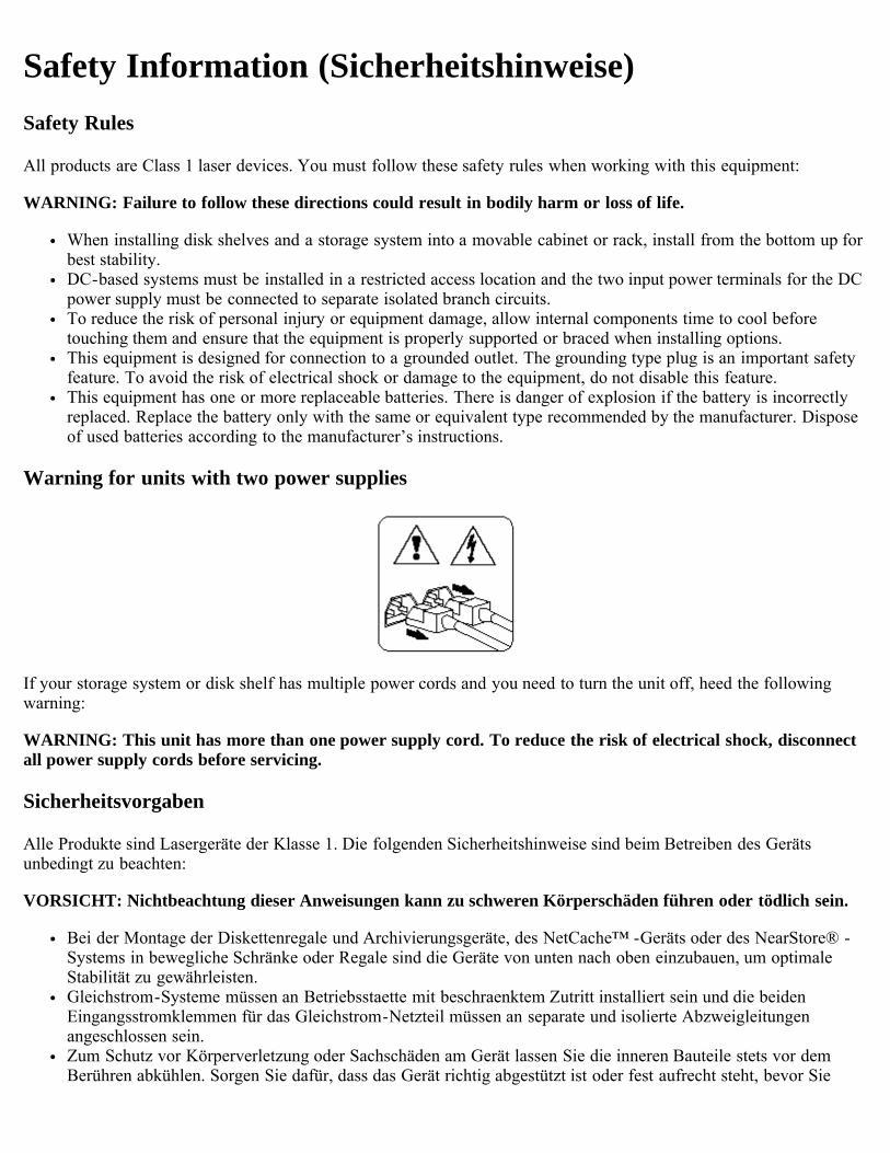
Warning for units with two power supplies
If your storage system or disk shelf has multiple power cords and you need to turn the unit off, heed the followingwarning:
WARNING: This unit has more than one power supply cord. To reduce the risk of electrical shock, disconnectall power supply cords before servicing.
Sicherheitsvorgaben
Alle Produkte sind Lasergeräte der Klasse 1. Die folgenden Sicherheitshinweise sind beim Betreiben des Gerätsunbedingt zu beachten:
VORSICHT: Nichtbeachtung dieser Anweisungen kann zu schweren Körperschäden führen oder tödlich sein.
Bei der Montage der Diskettenregale und Archivierungsgeräte, des NetCache™ -Geräts oder des NearStore® -Systems in bewegliche Schränke oder Regale sind die Geräte von unten nach oben einzubauen, um optimaleStabilität zu gewährleisten.Gleichstrom-Systeme müssen an Betriebsstaette mit beschraenktem Zutritt installiert sein und die beidenEingangsstromklemmen für das Gleichstrom-Netzteil müssen an separate und isolierte Abzweigleitungenangeschlossen sein.Zum Schutz vor Körperverletzung oder Sachschäden am Gerät lassen Sie die inneren Bauteile stets vor demBerühren abkühlen. Sorgen Sie dafür, dass das Gerät richtig abgestützt ist oder fest aufrecht steht, bevor Sie

neues Zubehör einbauen.Dieses Gerät ist für die Einspeisung aus einer geerdeten Netzverbindung ausgelegt. Der Netzstecker mitErdungsvorrichtung ist ein wichtiger Sicherheitsschutz. Zum Schutz vor elektrischem Schlag oder Sachschädenam Gerät die Erdung nicht abschalten.Das Gerät ist mit einer oder mehreren auswechselbaren Batterien ausgestattet. Bei unsachgemäßem Auswechselnder Batterie besteht Explosionsgefahr. Batterien nur mit dem vom Hersteller empfohlenen Typ oderentsprechenden Typen ersetzen. Gebrauchte Batterien sind gemäß den Anweisungen des Herstellers zuentsorgen.
Warnhinweis für Geräte mit mehr-fachen Netzan-schlussleitungen
Sollte Ihr Archiviergerät, NetCache-Gerät, NearStore-Gerät oder Diskettenregal mehrfache Netzanschlussleitungenaufweisen und Sie wollen das Gerät abschalten, bitte folgenden Warnhinweis beachten.
ACHTUNG: Gerät besitzt zwei Netzanschlussleitungen. Vor Wartung alle Anschlüsse vom Netz trennen.

Overview of the Diagnostics GuideThis section gives a high-level overview of what diagnostics are and gives some examples of when to run them.
This section discusses the following topics:
About diagnosticsOptional materialsBooting the diagnostics program
About diagnosticsThe Diagnostic Monitor
The Diagnostic Monitor is a set of diagnostics tools and tests that is used to search for and determine hardwareproblems. It is used as part of system troubleshooting to help isolate and identify a faulty component or to confirm thata specific component is operating properly.
When to run diagnostics
Typically, you run diagnostics after one of the following events happens on your system:
System panic is caused by an unidentified hardware failureAccess to a specific device becomes intermittent or the device becomes unavailableSystem response time becomes sluggish
The following scenarios are examples of when you might run diagnostics:
After the initial hardware installation
When you install your system for the first time, before you boot it, you can check the hardware components by runningthe all diagnostic. If any problems exist at the hardware level, you can learn about them before you boot the systemand connect it to the network.
When the system fails
When the system fails, test the system by first running the all diagnostic and then running individual diagnostics toisolate the cause of the failure.
When adding or replacing hardware
Before you add new hardware to your system, verify that the version of the Diagnostic Monitor you have in yoursystem supports the new hardware -- the notes in the download site applicable to your platform will provide someinformation on this.
When you add new hardware, such as disk shelves, or change hardware components, before you boot the system, runindividual diagnostics, such as fcal, to make sure that the disk shelf connections are sound.
When you replace a suspect component, run an individual diagnostic on the new component to check it before youboot the system. If the problem persists, it is not caused by the suspect component, but lies somewhere else.
If you suspect a problem in a specific hardware area
For example, you observed a lot of error messages of a specific type that point to a problem with the FC-ALconnection. This should lead you to run the fcal comprehensive diagnostic while the system is running. If the systempasses all tests except for the two tests that require a loopback plug, you might disconnect the system at an appropriatetime and run the Loop integrity and Read-only bus tests in extended mode.
Another example is a CPU fan error causing Data ONTAP™ software to panic and shut down the system. When youexamine the fan and see that it is spinning, a specific test of the fan might show that the fan is not spinning at the right

speed. Replacing the CPU fan should solve the problem.
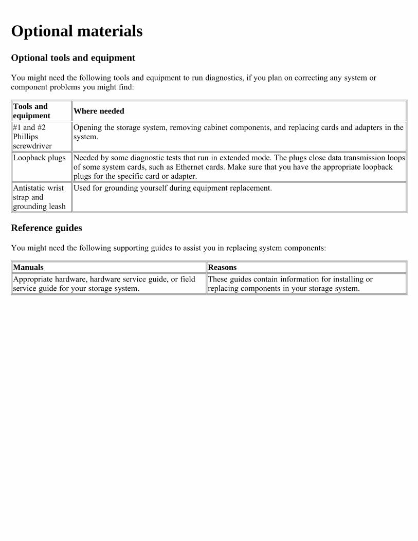
Optional materialsOptional tools and equipment
You might need the following tools and equipment to run diagnostics, if you plan on correcting any system orcomponent problems you might find:
Tools andequipment Where needed
#1 and #2Phillipsscrewdriver
Opening the storage system, removing cabinet components, and replacing cards and adapters in thesystem.
Loopback plugs Needed by some diagnostic tests that run in extended mode. The plugs close data transmission loopsof some system cards, such as Ethernet cards. Make sure that you have the appropriate loopbackplugs for the specific card or adapter.
Antistatic wriststrap andgrounding leash
Used for grounding yourself during equipment replacement.
Reference guides
You might need the following supporting guides to assist you in replacing system components:
Manuals ReasonsAppropriate hardware, hardware service guide, or fieldservice guide for your storage system.
These guides contain information for installing orreplacing components in your storage system.
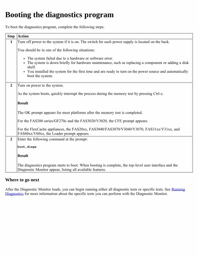
Booting the diagnostics programTo boot the diagnostics program, complete the following steps:
Step Action1 Turn off power to the system if it is on. The switch for each power supply is located on the back.
You should be in one of the following situations:
The system failed due to a hardware or software error.The system is down briefly for hardware maintenance, such as replacing a component or adding a diskshelf.You installed the system for the first time and are ready to turn on the power source and automaticallyboot the system.
2 Turn on power to the system.
As the system boots, quickly interrupt the process during the memory test by pressing Ctrl-c.
Result
The OK prompt appears for most platforms after the memory test is completed.
For the FAS200 series/GF270c and the FAS3020/V3020, the CFE prompt appears.
For the FlexCache appliances, the FAS20xx, FAS3040/FAS3070/V3040/V3070, FAS31xx/V31xx, andFAS60xx/V60xx, the Loader prompt appears.
2 Enter the following command at the prompt:
boot_diags
Result
The diagnostics program starts to boot. When booting is complete, the top-level user interface and theDiagnostic Monitor appear, listing all available features.
Where to go next
After the Diagnostic Monitor loads, you can begin running either all diagnostic tests or specific tests. See RunningDiagnostics for more information about the specific tests you can perform with the Diagnostic Monitor.
Running DiagnosticsAbout this section
This section describes the Diagnostic Monitor and how to run diagnostics on your system.
Topics in this section
This section discusses the following topics:
Diagnostic Monitor user interfaceRunning diagnostic tests
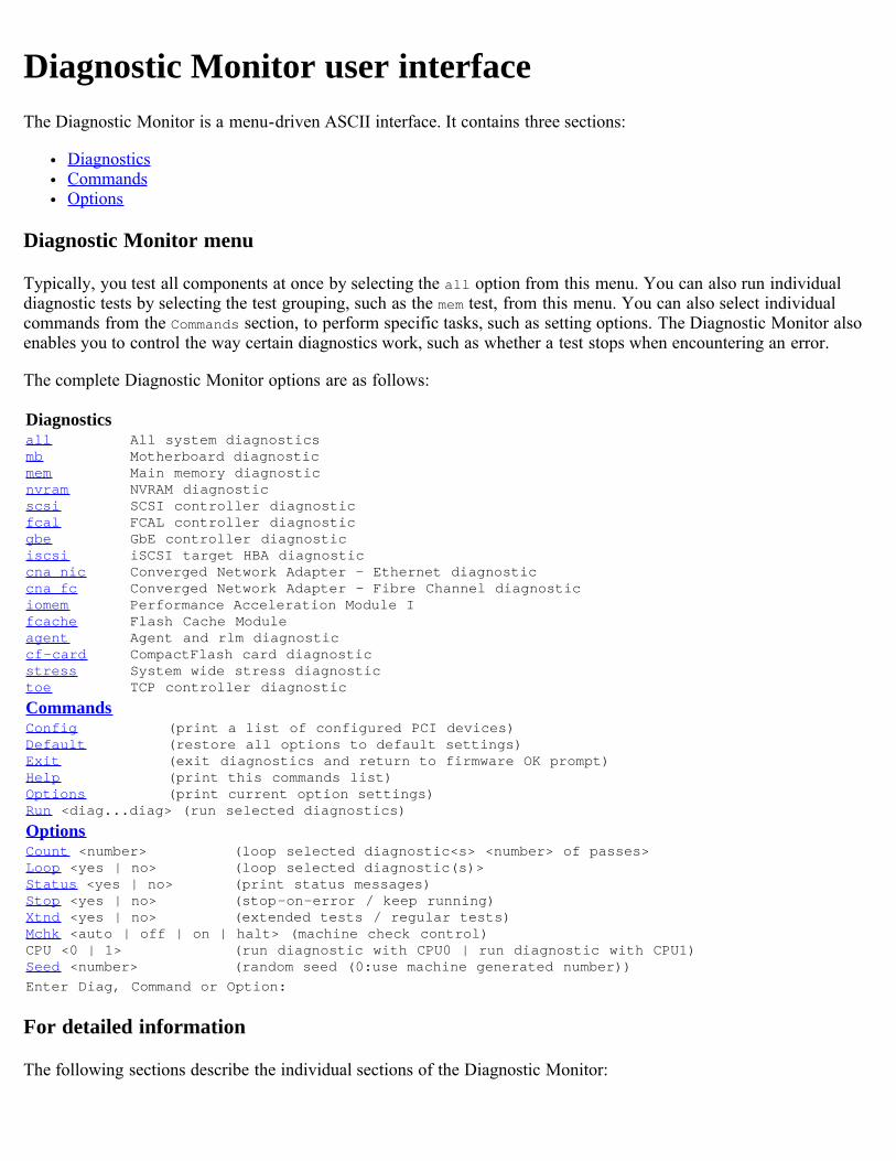
Diagnostic Monitor user interfaceThe Diagnostic Monitor is a menu-driven ASCII interface. It contains three sections:
DiagnosticsCommandsOptions
Diagnostic Monitor menu
Typically, you test all components at once by selecting the all option from this menu. You can also run individualdiagnostic tests by selecting the test grouping, such as the mem test, from this menu. You can also select individualcommands from the Commands section, to perform specific tasks, such as setting options. The Diagnostic Monitor alsoenables you to control the way certain diagnostics work, such as whether a test stops when encountering an error.
The complete Diagnostic Monitor options are as follows:
Diagnosticsall All system diagnosticsmb Motherboard diagnosticmem Main memory diagnosticnvram NVRAM diagnosticscsi SCSI controller diagnosticfcal FCAL controller diagnosticgbe GbE controller diagnosticiscsi iSCSI target HBA diagnosticcna_nic Converged Network Adapter - Ethernet diagnosticcna_fc Converged Network Adapter - Fibre Channel diagnosticiomem Performance Acceleration Module Ifcache Flash Cache Moduleagent Agent and rlm diagnosticcf-card CompactFlash card diagnosticstress System wide stress diagnostictoe TCP controller diagnostic
CommandsConfig (print a list of configured PCI devices)Default (restore all options to default settings)Exit (exit diagnostics and return to firmware OK prompt)Help (print this commands list)Options (print current option settings)Run <diag...diag> (run selected diagnostics)
OptionsCount <number> (loop selected diagnostic<s> <number> of passes>Loop <yes | no> (loop selected diagnostic(s)>Status <yes | no> (print status messages)Stop <yes | no> (stop-on-error / keep running)Xtnd <yes | no> (extended tests / regular tests)Mchk <auto | off | on | halt> (machine check control)CPU <0 | 1> (run diagnostic with CPU0 | run diagnostic with CPU1)Seed <number> (random seed (0:use machine generated number))Enter Diag, Command or Option:
For detailed information
The following sections describe the individual sections of the Diagnostic Monitor:

Diagnostics menu optionsCommands menu optionsOptions menu options
[ Up ] [ Diagnostics menu options ] [ Commands menu options ] [ Options menu options ]
Diagnostic Monitor user interface
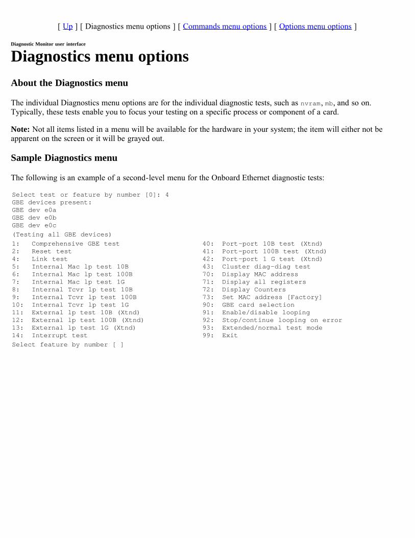
Diagnostics menu optionsAbout the Diagnostics menu
The individual Diagnostics menu options are for the individual diagnostic tests, such as nvram, mb, and so on.Typically, these tests enable you to focus your testing on a specific process or component of a card.
Note: Not all items listed in a menu will be available for the hardware in your system; the item will either not beapparent on the screen or it will be grayed out.
Sample Diagnostics menu
The following is an example of a second-level menu for the Onboard Ethernet diagnostic tests:
Select test or feature by number [0]: 4GBE devices present:GBE dev e0aGBE dev e0bGBE dev e0c(Testing all GBE devices)1: Comprehensive GBE test 40: Port-port 10B test (Xtnd)2: Reset test 41: Port-port 100B test (Xtnd)4: Link test 42: Port-port 1 G test (Xtnd)5: Internal Mac lp test 10B 43: Cluster diag-diag test6: Internal Mac lp test 100B 70: Display MAC address7: Internal Mac lp test 1G 71: Display all registers8: Internal Tcvr lp test 10B 72: Display Counters9: Internal Tcvr lp test 100B 73: Set MAC address [Factory]10: Internal Tcvr lp test 1G 90: GBE card selection11: External lp test 10B (Xtnd) 91: Enable/disable looping12: External lp test 100B (Xtnd) 92: Stop/continue looping on error13: External lp test 1G (Xtnd) 93: Extended/normal test mode14: Interrupt test 99: ExitSelect feature by number [ ]
[ Up ] [ Diagnostics menu options ] [ Commands menu options ] [ Options menu options ]
Diagnostic Monitor user interface
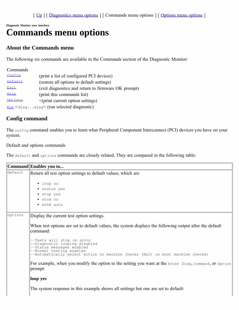
Commands menu optionsAbout the Commands menu
The following six commands are available in the Commands section of the Diagnostic Monitor:
CommandsConfig (print a list of configured PCI devices)Default (restore all options to default settings)Exit (exit diagnostics and return to firmware OK prompt)Help (print this commands list)Options <(print current option settings)Run <diag...diag> (run selected diagnostic)
Config command
The config command enables you to learn what Peripheral Component Interconnect (PCI) devices you have on yoursystem.
Default and options commands
The default and options commands are closely related. They are compared in the following table:
Command Enables you to...default Return all test option settings to default values, which are
loop nostatus yesstop yesxtnd nomchk auto
options Display the current test option settings.
When test options are set to default values, the system displays the following output after the defaultcommand:
--Tests will stop on error --Diagnostic looping disabled --Status messages enabled --Normal testing enabled --Automatically select action on machine checks (Halt on most machine checks)
For example, when you modify the option to the setting you want at the Enter Diag, Command, or Optionprompt:
loop yes
The system response in this example shows all settings but one are set to default:
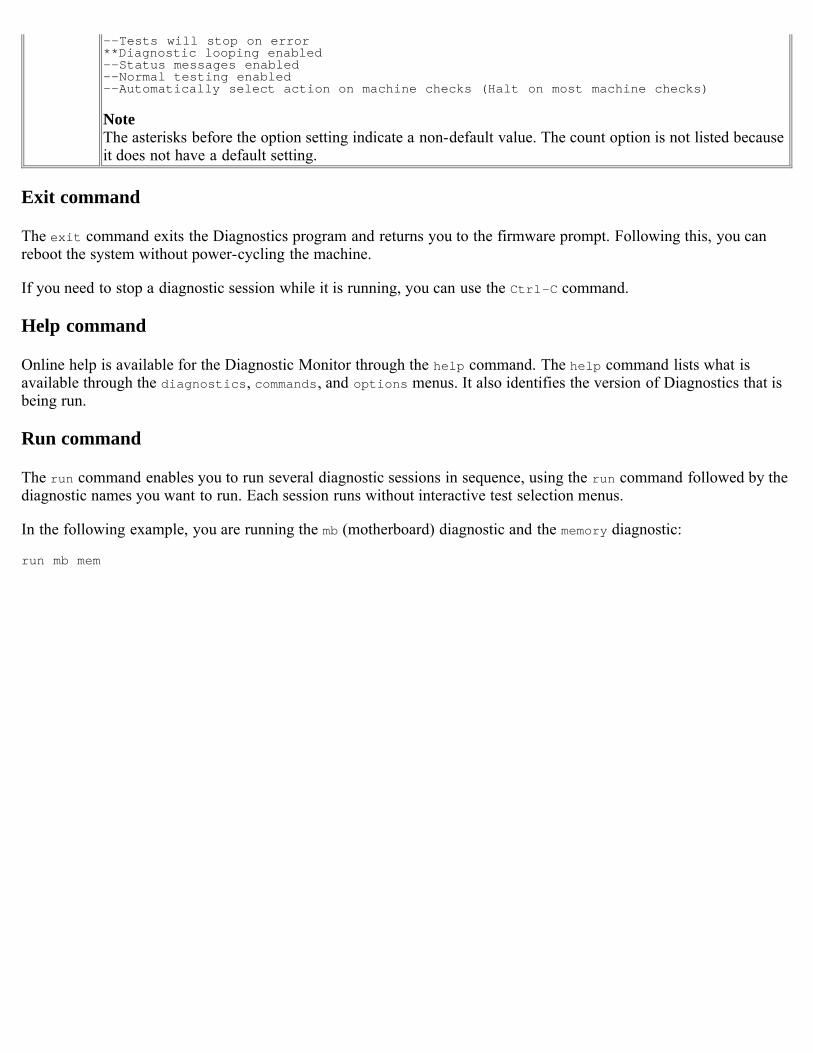
--Tests will stop on error **Diagnostic looping enabled --Status messages enabled --Normal testing enabled --Automatically select action on machine checks (Halt on most machine checks)
NoteThe asterisks before the option setting indicate a non-default value. The count option is not listed becauseit does not have a default setting.
Exit command
The exit command exits the Diagnostics program and returns you to the firmware prompt. Following this, you canreboot the system without power-cycling the machine.
If you need to stop a diagnostic session while it is running, you can use the Ctrl-C command.
Help command
Online help is available for the Diagnostic Monitor through the help command. The help command lists what isavailable through the diagnostics, commands, and options menus. It also identifies the version of Diagnostics that isbeing run.
Run command
The run command enables you to run several diagnostic sessions in sequence, using the run command followed by thediagnostic names you want to run. Each session runs without interactive test selection menus.
In the following example, you are running the mb (motherboard) diagnostic and the memory diagnostic:
run mb mem
[ Up ] [ Diagnostics menu options ] [ Commands menu options ] [ Options menu options ]
Diagnostic Monitor user interface
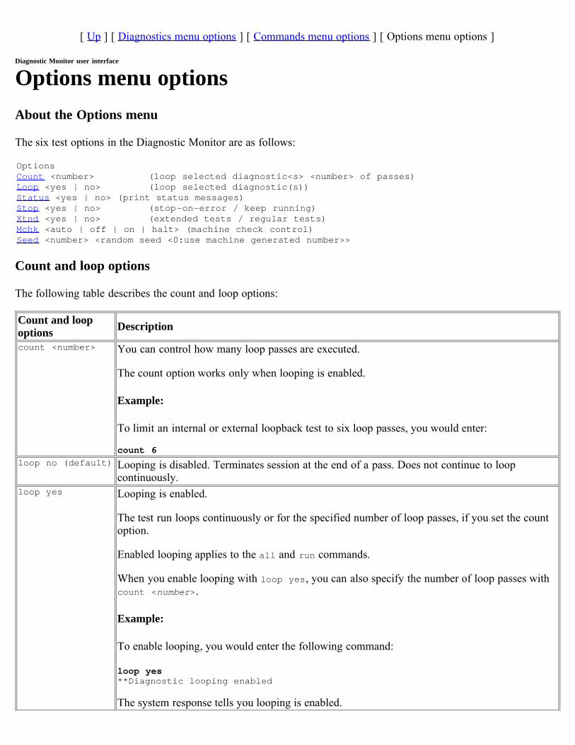
Options menu optionsAbout the Options menu
The six test options in the Diagnostic Monitor are as follows:
OptionsCount <number> (loop selected diagnostic<s> <number> of passes)Loop <yes | no> (loop selected diagnostic(s))Status <yes | no> (print status messages)Stop <yes | no> (stop-on-error / keep running)Xtnd <yes | no> (extended tests / regular tests)Mchk <auto | off | on | halt> (machine check control)Seed <number> <random seed <0:use machine generated number>>
Count and loop options
The following table describes the count and loop options:
Count and loopoptions Description
count <number> You can control how many loop passes are executed.
The count option works only when looping is enabled.
Example:
To limit an internal or external loopback test to six loop passes, you would enter:
count 6loop no (default) Looping is disabled. Terminates session at the end of a pass. Does not continue to loop
continuously.loop yes Looping is enabled.
The test run loops continuously or for the specified number of loop passes, if you set the countoption.
Enabled looping applies to the all and run commands.
When you enable looping with loop yes, you can also specify the number of loop passes withcount <number>.
Example:
To enable looping, you would enter the following command:
loop yes **Diagnostic looping enabled
The system response tells you looping is enabled.
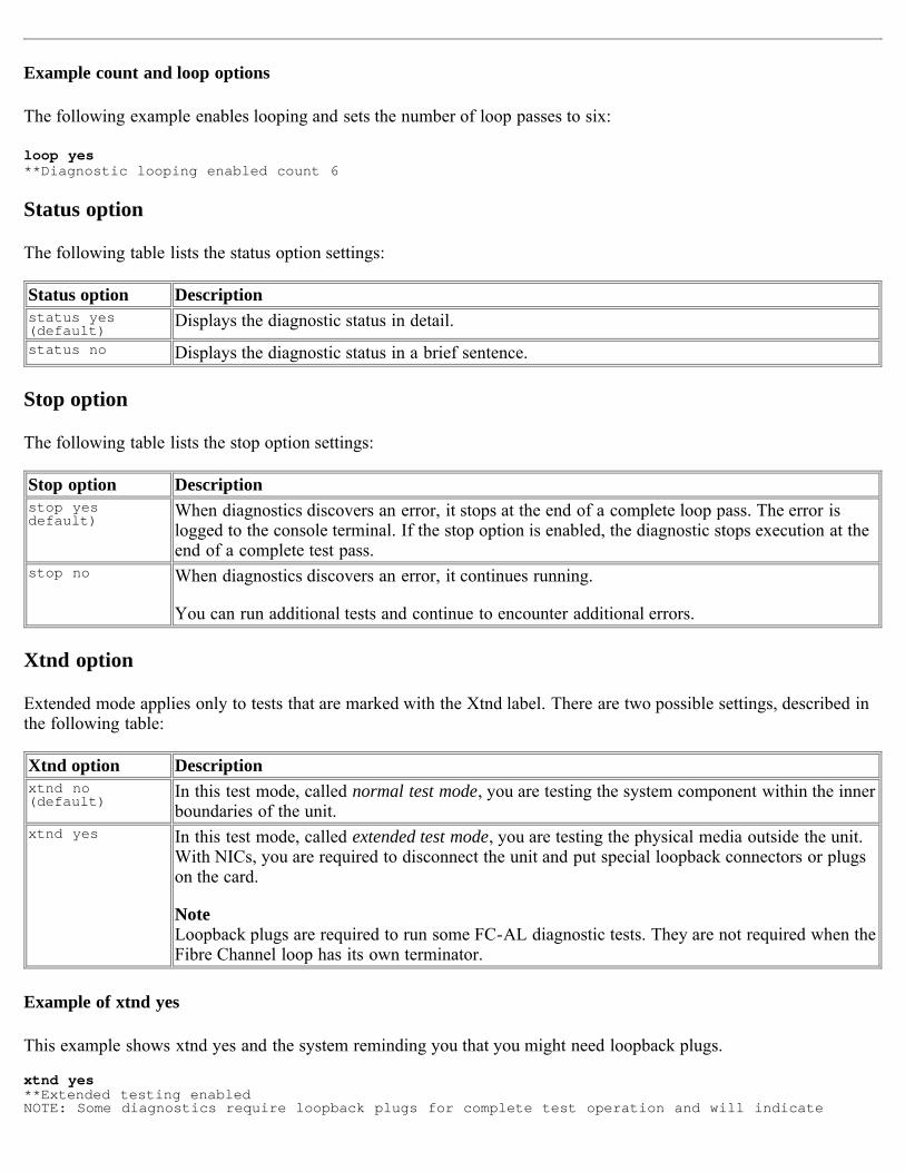
Example count and loop options
The following example enables looping and sets the number of loop passes to six:
loop yes **Diagnostic looping enabled count 6
Status option
The following table lists the status option settings:
Status option Descriptionstatus yes(default)
Displays the diagnostic status in detail.status no Displays the diagnostic status in a brief sentence.
Stop option
The following table lists the stop option settings:
Stop option Descriptionstop yesdefault)
When diagnostics discovers an error, it stops at the end of a complete loop pass. The error islogged to the console terminal. If the stop option is enabled, the diagnostic stops execution at theend of a complete test pass.
stop no When diagnostics discovers an error, it continues running.
You can run additional tests and continue to encounter additional errors.
Xtnd option
Extended mode applies only to tests that are marked with the Xtnd label. There are two possible settings, described inthe following table:
Xtnd option Descriptionxtnd no(default)
In this test mode, called normal test mode, you are testing the system component within the innerboundaries of the unit.
xtnd yes In this test mode, called extended test mode, you are testing the physical media outside the unit.With NICs, you are required to disconnect the unit and put special loopback connectors or plugson the card.
NoteLoopback plugs are required to run some FC-AL diagnostic tests. They are not required when theFibre Channel loop has its own terminator.
Example of xtnd yes
This example shows xtnd yes and the system reminding you that you might need loopback plugs.
xtnd yes**Extended testing enabled NOTE: Some diagnostics require loopback plugs for complete test operation and will indicate
failures without these plugs.
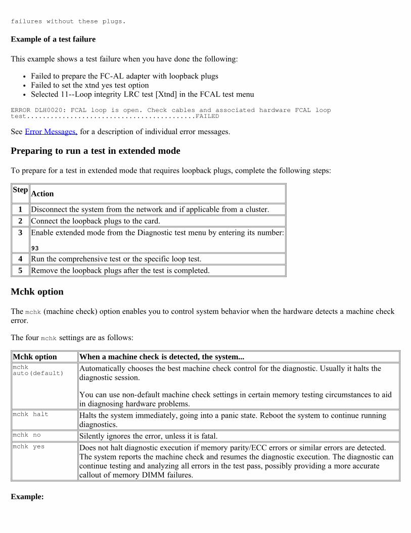
Example of a test failure
This example shows a test failure when you have done the following:
Failed to prepare the FC-AL adapter with loopback plugsFailed to set the xtnd yes test optionSelected 11--Loop integrity LRC test [Xtnd] in the FCAL test menu
ERROR DLH0020: FCAL loop is open. Check cables and associated hardware FCAL looptest...........................................FAILED
See Error Messages, for a description of individual error messages.
Preparing to run a test in extended mode
To prepare for a test in extended mode that requires loopback plugs, complete the following steps:
Step Action
1 Disconnect the system from the network and if applicable from a cluster. 2 Connect the loopback plugs to the card.3 Enable extended mode from the Diagnostic test menu by entering its number:
93
4 Run the comprehensive test or the specific loop test.5 Remove the loopback plugs after the test is completed.
Mchk option
The mchk (machine check) option enables you to control system behavior when the hardware detects a machine checkerror.
The four mchk settings are as follows:
Mchk option When a machine check is detected, the system...mchkauto(default)
Automatically chooses the best machine check control for the diagnostic. Usually it halts thediagnostic session.
You can use non-default machine check settings in certain memory testing circumstances to aidin diagnosing hardware problems.
mchk halt Halts the system immediately, going into a panic state. Reboot the system to continue runningdiagnostics.
mchk no Silently ignores the error, unless it is fatal.mchk yes Does not halt diagnostic execution if memory parity/ECC errors or similar errors are detected.
The system reports the machine check and resumes the diagnostic execution. The diagnostic cancontinue testing and analyzing all errors in the test pass, possibly providing a more accuratecallout of memory DIMM failures.
Example:
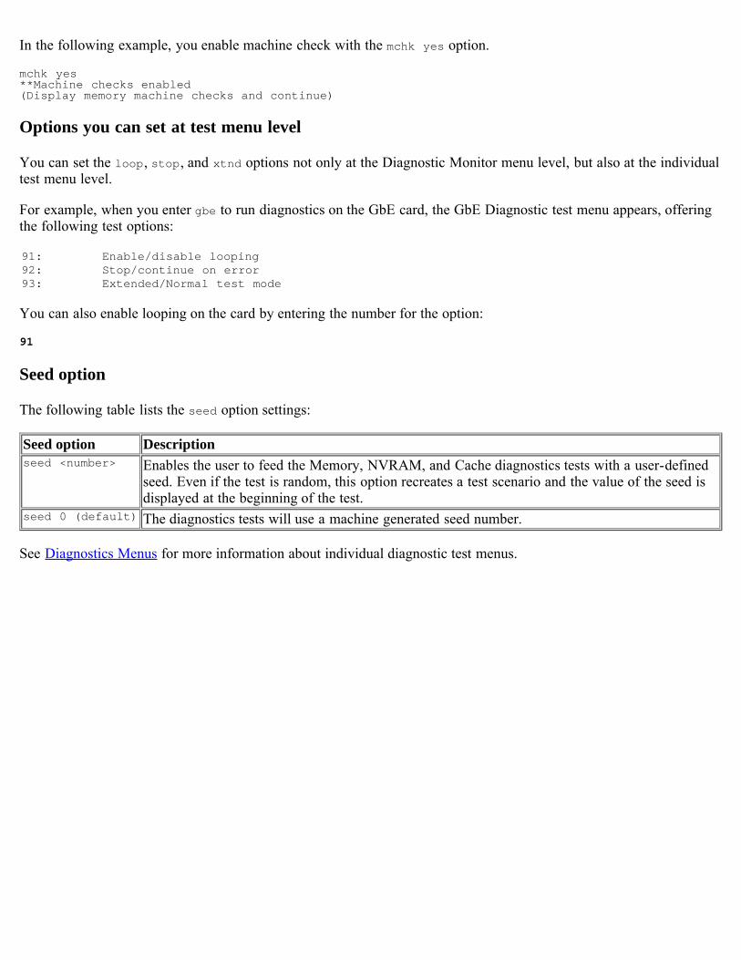
In the following example, you enable machine check with the mchk yes option.
mchk yes **Machine checks enabled (Display memory machine checks and continue)
Options you can set at test menu level
You can set the loop, stop, and xtnd options not only at the Diagnostic Monitor menu level, but also at the individualtest menu level.
For example, when you enter gbe to run diagnostics on the GbE card, the GbE Diagnostic test menu appears, offeringthe following test options:
91: Enable/disable looping92: Stop/continue on error93: Extended/Normal test mode
You can also enable looping on the card by entering the number for the option:
91
Seed option
The following table lists the seed option settings:
Seed option Descriptionseed <number> Enables the user to feed the Memory, NVRAM, and Cache diagnostics tests with a user-defined
seed. Even if the test is random, this option recreates a test scenario and the value of the seed isdisplayed at the beginning of the test.
seed 0 (default) The diagnostics tests will use a machine generated seed number.
See Diagnostics Menus for more information about individual diagnostic test menus.
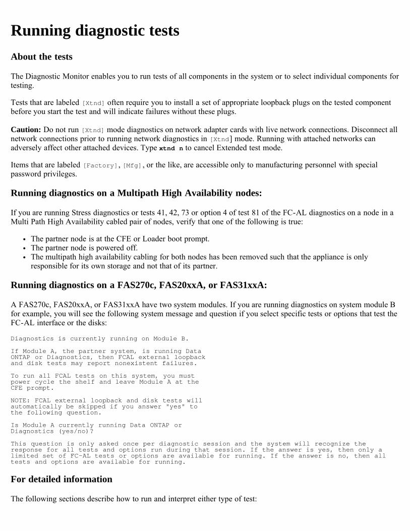
Running diagnostic testsAbout the tests
The Diagnostic Monitor enables you to run tests of all components in the system or to select individual components fortesting.
Tests that are labeled [Xtnd] often require you to install a set of appropriate loopback plugs on the tested componentbefore you start the test and will indicate failures without these plugs.
Caution: Do not run [Xtnd] mode diagnostics on network adapter cards with live network connections. Disconnect allnetwork connections prior to running network diagnostics in [Xtnd] mode. Running with attached networks canadversely affect other attached devices. Type xtnd n to cancel Extended test mode.
Items that are labeled [Factory], [Mfg], or the like, are accessible only to manufacturing personnel with specialpassword privileges.
Running diagnostics on a Multipath High Availability nodes:
If you are running Stress diagnostics or tests 41, 42, 73 or option 4 of test 81 of the FC-AL diagnostics on a node in aMulti Path High Availability cabled pair of nodes, verify that one of the following is true:
The partner node is at the CFE or Loader boot prompt.The partner node is powered off.The multipath high availability cabling for both nodes has been removed such that the appliance is onlyresponsible for its own storage and not that of its partner.
Running diagnostics on a FAS270c, FAS20xxA, or FAS31xxA:
A FAS270c, FAS20xxA, or FAS31xxA have two system modules. If you are running diagnostics on system module Bfor example, you will see the following system message and question if you select specific tests or options that test theFC-AL interface or the disks:
Diagnostics is currently running on Module B.
If Module A, the partner system, is running Data ONTAP or Diagnostics, then FCAL external loopback and disk tests may report nonexistent failures.
To run all FCAL tests on this system, you must power cycle the shelf and leave Module A at the CFE prompt.
NOTE: FCAL external loopback and disk tests will automatically be skipped if you answer "yes" to the following question.
Is Module A currently running Data ONTAP or Diagnostics (yes/no)?
This question is only asked once per diagnostic session and the system will recognize theresponse for all tests and options run during that session. If the answer is yes, then only alimited set of FC-AL tests or options are available for running. If the answer is no, then alltests and options are available for running.
For detailed information
The following sections describe how to run and interpret either type of test:

Running all diagnostic testsRunning individual diagnostic testsTest results
[ Up ] [ Running all diagnostics tests ] [ Running individual diagnostics tests ] [ Test results ]
Running diagnostic tests
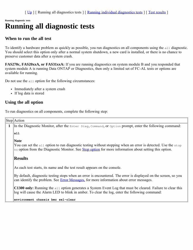
Running all diagnostic testsWhen to run the all test
To identify a hardware problem as quickly as possible, you run diagnostics on all components using the all diagnostic.You should select this option only after a normal system shutdown, a new card is installed, or there is no chance topreserve customer data after a system crash.
FAS270c, FAS20xxA, or FAS31xxA: If you are running diagnostics on system module B and you responded thatsystem module A is running Data ONTAP or Diagnostics, then only a limited set of FC-AL tests or options areavailable for running.
Do not use the all option for the following circumstances:
Immediately after a system crashIf log data is stored
Using the all option
To run diagnostics on all components, complete the following step:
Step Action1 In the Diagnostic Monitor, after the Enter Diag, Command, or Option prompt, enter the following command:
all
NoteYou can set the all option to run diagnostic testing without stopping when an error is detected. Use the stopno option from the Diagnostic Monitor. See Stop option for more information about setting this option.
Results
As each test starts, its name and the test result appears on the console.
By default, diagnostic testing stops when an error is encountered. The error is displayed on the screen, so youcan identify the problem. See Error Messages, for more information about error messages.
C1300 only: Running the all option generates a System Event Log that must be cleared. Failure to clear thislog will cause the Alarm LED to blink in amber. To clear the log, enter the following command:
environment chassis bmc sel-clear
[ Up ] [ Running all diagnostics tests ] [ Running individual diagnostics tests ] [ Test results ]
Running diagnostic tests
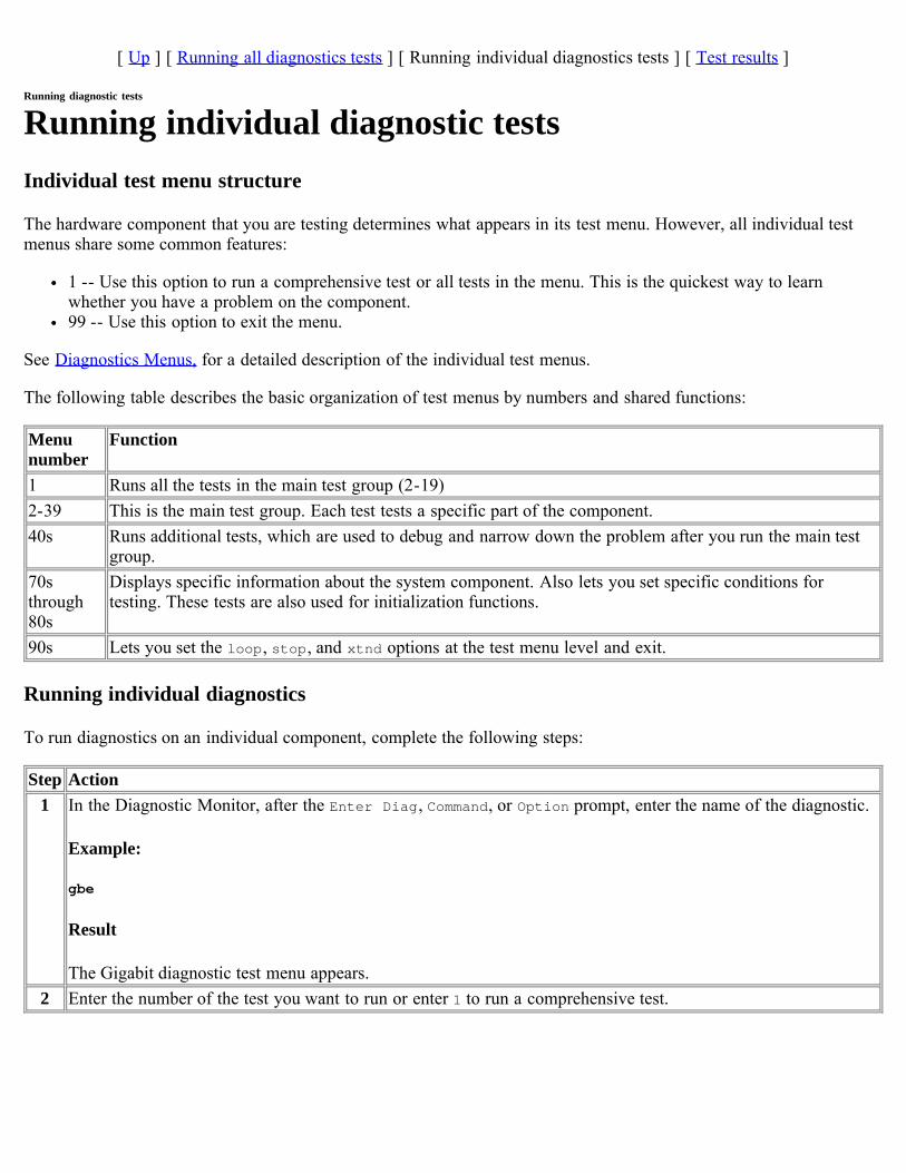
Running individual diagnostic testsIndividual test menu structure
The hardware component that you are testing determines what appears in its test menu. However, all individual testmenus share some common features:
1 -- Use this option to run a comprehensive test or all tests in the menu. This is the quickest way to learnwhether you have a problem on the component.99 -- Use this option to exit the menu.
See Diagnostics Menus, for a detailed description of the individual test menus.
The following table describes the basic organization of test menus by numbers and shared functions:
Menunumber
Function
1 Runs all the tests in the main test group (2-19)2-39 This is the main test group. Each test tests a specific part of the component.40s Runs additional tests, which are used to debug and narrow down the problem after you run the main test
group.70sthrough80s
Displays specific information about the system component. Also lets you set specific conditions fortesting. These tests are also used for initialization functions.
90s Lets you set the loop, stop, and xtnd options at the test menu level and exit.
Running individual diagnostics
To run diagnostics on an individual component, complete the following steps:
Step Action1 In the Diagnostic Monitor, after the Enter Diag, Command, or Option prompt, enter the name of the diagnostic.
Example:
gbe
Result
The Gigabit diagnostic test menu appears.2 Enter the number of the test you want to run or enter 1 to run a comprehensive test.
[ Up ] [ Running all diagnostics tests ] [ Running individual diagnostics tests ] [ Test results ]
Running diagnostic tests
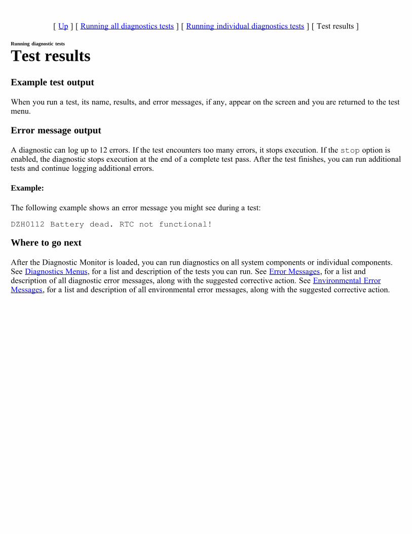
Test resultsExample test output
When you run a test, its name, results, and error messages, if any, appear on the screen and you are returned to the testmenu.
Error message output
A diagnostic can log up to 12 errors. If the test encounters too many errors, it stops execution. If the stop option isenabled, the diagnostic stops execution at the end of a complete test pass. After the test finishes, you can run additionaltests and continue logging additional errors.
Example:
The following example shows an error message you might see during a test:
DZH0112 Battery dead. RTC not functional!
Where to go next
After the Diagnostic Monitor is loaded, you can run diagnostics on all system components or individual components.See Diagnostics Menus, for a list and description of the tests you can run. See Error Messages, for a list anddescription of all diagnostic error messages, along with the suggested corrective action. See Environmental ErrorMessages, for a list and description of all environmental error messages, along with the suggested corrective action.
Diagnostics MenusAbout this section
This section lists and defines the menu options of the Diagnostic Monitor's individual diagnostic tests.
If you receive an error message during a particular test, go to Error Messages, to determine what the message meansand to determine how to correct the problem encountered by the test.
Topics in this section
This section discusses the following topics.
Motherboard diagnosticsMain memory diagnosticsCard diagnosticsCompactFlash card diagnosticsStress diagnostics
Motherboard diagnosticsAbout motherboard diagnostics
The motherboard diagnostic test the integrity of a variety of components on the motherboard or system backplane. Thedata you retrieve from these tests helps you determine what component is causing an error.
For example, if you want to check the PCI devices and slots on the motherboard, you select the Misc. boardcomponent menu option, then select the appropriate test from the Miscellaneous board component tests submenu.
For detailed information
For detailed information about the motherboard and backplane diagnostic menus, see the following sections:
FAS200 seriesFAS20xx/SA200FAS3020/V3020FAS3040/FAS3070/V3040/V3070FAS31xx/V31xxFAS60xx/V60xx/SA600
Diagnostics Menus - Motherboard
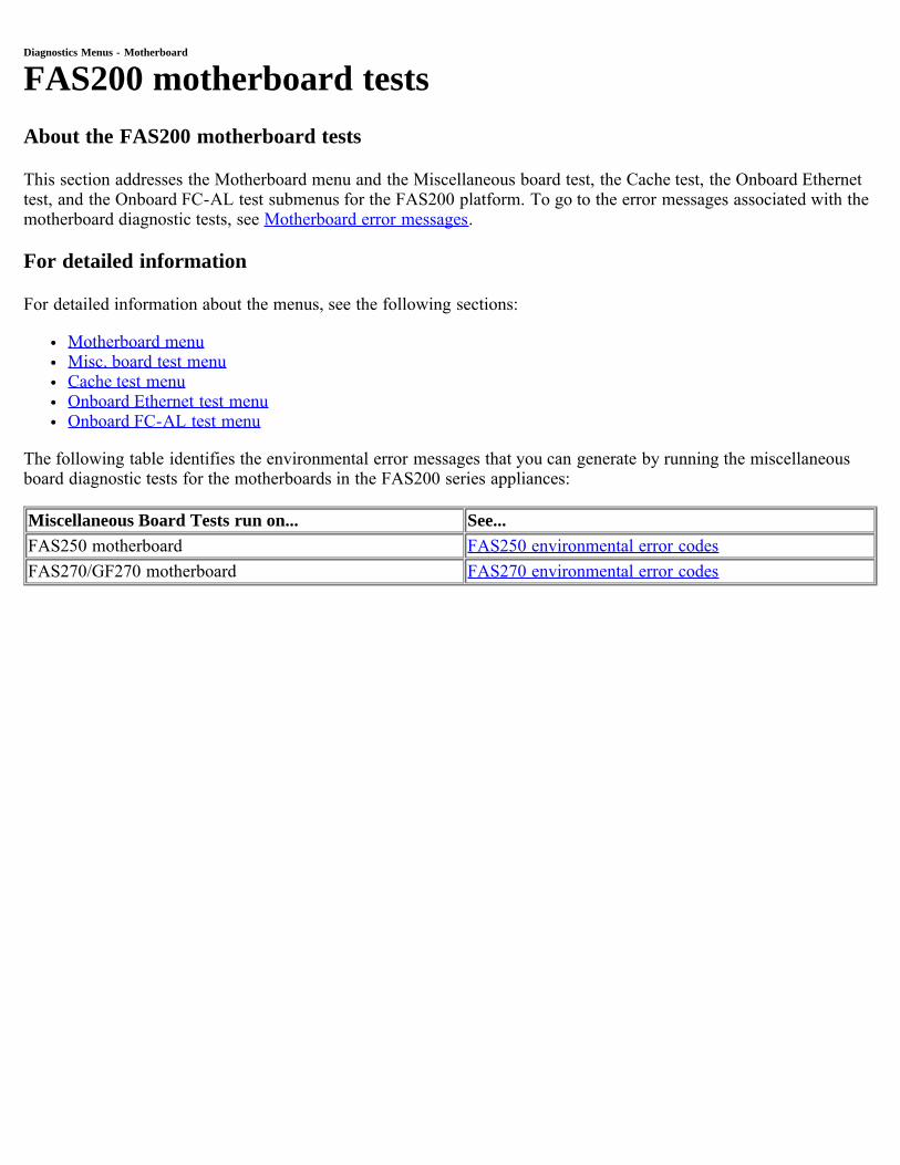
FAS200 motherboard testsAbout the FAS200 motherboard tests
This section addresses the Motherboard menu and the Miscellaneous board test, the Cache test, the Onboard Ethernettest, and the Onboard FC-AL test submenus for the FAS200 platform. To go to the error messages associated with themotherboard diagnostic tests, see Motherboard error messages.
For detailed information
For detailed information about the menus, see the following sections:
Motherboard menuMisc. board test menuCache test menuOnboard Ethernet test menuOnboard FC-AL test menu
The following table identifies the environmental error messages that you can generate by running the miscellaneousboard diagnostic tests for the motherboards in the FAS200 series appliances:
Miscellaneous Board Tests run on... See...FAS250 motherboard FAS250 environmental error codesFAS270/GF270 motherboard FAS270 environmental error codes
[ Up ] [ Motherboard ] [ Miscellaneous test ] [ Cache test ] [ Onboard Ethernet ] [ Onboard FC-AL ]
Motherboard menu and submenus
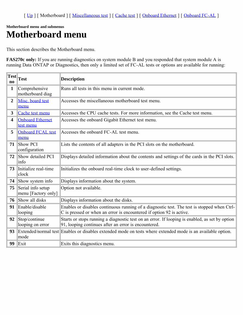
Motherboard menuThis section describes the Motherboard menu.
FAS270c only: If you are running diagnostics on system module B and you responded that system module A isrunning Data ONTAP or Diagnostics, then only a limited set of FC-AL tests or options are available for running:
Testno Test Description
1 Comprehensivemotherboard diag
Runs all tests in this menu in current mode.
2 Misc. board testmenu
Accesses the miscellaneous motherboard test menu.
3 Cache test menu Accesses the CPU cache tests. For more information, see the Cache test menu.4 Onboard Ethernet
test menuAccesses the onboard Gigabit Ethernet test menu.
5 Onboard FCAL testmenu
Accesses the onboard FC-AL test menu.
71 Show PCIconfiguration
Lists the contents of all adapters in the PCI slots on the motherboard.
72 Show detailed PCIinfo
Displays detailed information about the contents and settings of the cards in the PCI slots.
73 Initialize real-timeclock
Initializes the onboard real-time clock to user-defined settings.
74 Show system info Displays information about the system.75 Serial info setup
menu [Factory only]Option not available.
76 Show all disks Displays information about the disks.91 Enable/disable
loopingEnables or disables continuous running of a diagnostic test. The test is stopped when Ctrl-C is pressed or when an error is encountered if option 92 is active.
92 Stop/continuelooping on error
Starts or stops running a diagnostic test on an error. If looping is enabled, as set by option91, looping continues after an error is encountered.
93 Extended/normal testmode
Enables or disables extended mode on tests where extended mode is an available option.
99 Exit Exits this diagnostics menu.
[ Up ] [ Motherboard ] [ Miscellaneous test ] [ Cache test ] [ Onboard Ethernet ] [ Onboard FC-AL ]
Motherboard menu and submenus
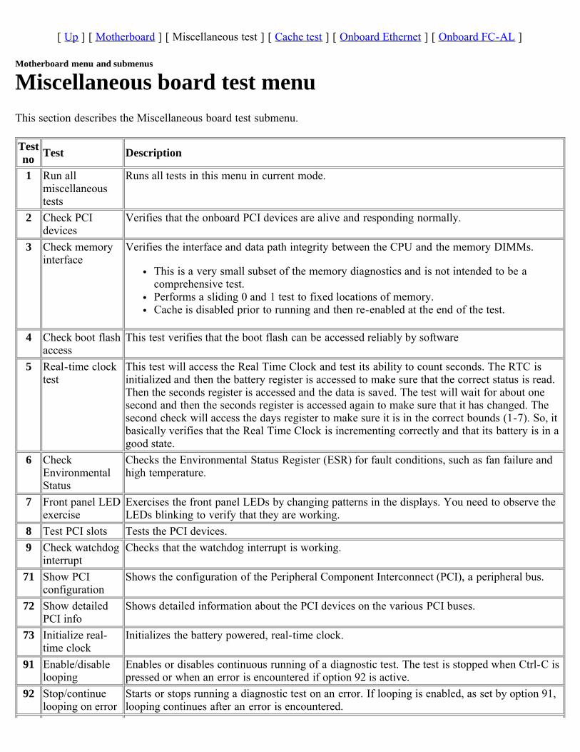
Miscellaneous board test menuThis section describes the Miscellaneous board test submenu.
Testno Test Description
1 Run allmiscellaneoustests
Runs all tests in this menu in current mode.
2 Check PCIdevices
Verifies that the onboard PCI devices are alive and responding normally.
3 Check memoryinterface
Verifies the interface and data path integrity between the CPU and the memory DIMMs.
This is a very small subset of the memory diagnostics and is not intended to be acomprehensive test.Performs a sliding 0 and 1 test to fixed locations of memory.Cache is disabled prior to running and then re-enabled at the end of the test.
4 Check boot flashaccess
This test verifies that the boot flash can be accessed reliably by software
5 Real-time clocktest
This test will access the Real Time Clock and test its ability to count seconds. The RTC isinitialized and then the battery register is accessed to make sure that the correct status is read.Then the seconds register is accessed and the data is saved. The test will wait for about onesecond and then the seconds register is accessed again to make sure that it has changed. Thesecond check will access the days register to make sure it is in the correct bounds (1-7). So, itbasically verifies that the Real Time Clock is incrementing correctly and that its battery is in agood state.
6 CheckEnvironmentalStatus
Checks the Environmental Status Register (ESR) for fault conditions, such as fan failure andhigh temperature.
7 Front panel LEDexercise
Exercises the front panel LEDs by changing patterns in the displays. You need to observe theLEDs blinking to verify that they are working.
8 Test PCI slots Tests the PCI devices.9 Check watchdog
interruptChecks that the watchdog interrupt is working.
71 Show PCIconfiguration
Shows the configuration of the Peripheral Component Interconnect (PCI), a peripheral bus.
72 Show detailedPCI info
Shows detailed information about the PCI devices on the various PCI buses.
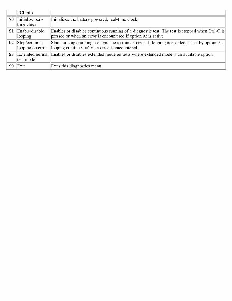
73 Initialize real-time clock
Initializes the battery powered, real-time clock.
91 Enable/disablelooping
Enables or disables continuous running of a diagnostic test. The test is stopped when Ctrl-C ispressed or when an error is encountered if option 92 is active.
92 Stop/continuelooping on error
Starts or stops running a diagnostic test on an error. If looping is enabled, as set by option 91,looping continues after an error is encountered.

93 Extended/normaltest mode
Enables or disables extended mode on tests where extended mode is an available option.
99 Exit Exits this diagnostics menu.
[ Up ] [ Motherboard ] [ Miscellaneous test ] [ Cache test ] [ Onboard Ethernet ] [ Onboard FC-AL ]
Motherboard menu and submenus
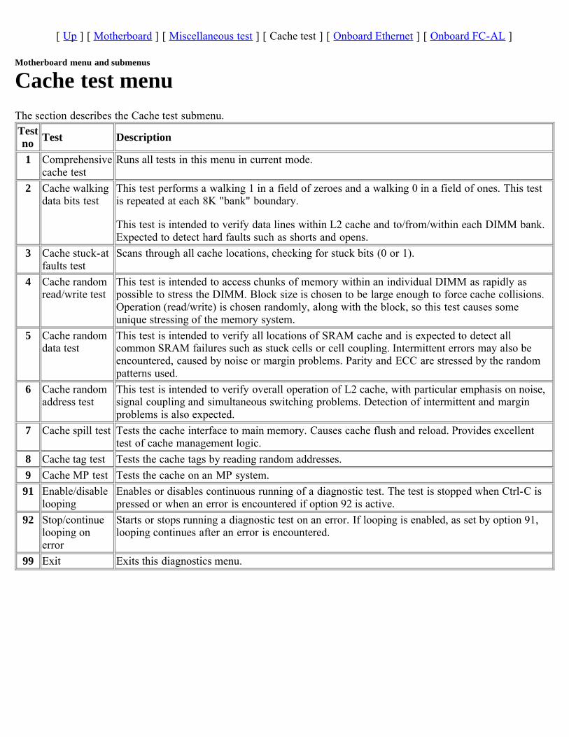
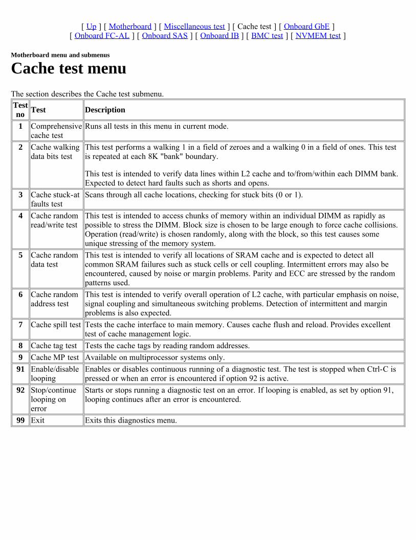
Cache test menuThe section describes the Cache test submenu.Testno Test Description
1 Comprehensivecache test
Runs all tests in this menu in current mode.
2 Cache walkingdata bits test
This test performs a walking 1 in a field of zeroes and a walking 0 in a field of ones. This testis repeated at each 8K "bank" boundary.
This test is intended to verify data lines within L2 cache and to/from/within each DIMM bank.Expected to detect hard faults such as shorts and opens.
3 Cache stuck-atfaults test
Scans through all cache locations, checking for stuck bits (0 or 1).
4 Cache randomread/write test
This test is intended to access chunks of memory within an individual DIMM as rapidly aspossible to stress the DIMM. Block size is chosen to be large enough to force cache collisions.Operation (read/write) is chosen randomly, along with the block, so this test causes someunique stressing of the memory system.
5 Cache randomdata test
This test is intended to verify all locations of SRAM cache and is expected to detect allcommon SRAM failures such as stuck cells or cell coupling. Intermittent errors may also beencountered, caused by noise or margin problems. Parity and ECC are stressed by the randompatterns used.
6 Cache randomaddress test
This test is intended to verify overall operation of L2 cache, with particular emphasis on noise,signal coupling and simultaneous switching problems. Detection of intermittent and marginproblems is also expected.
7 Cache spill test Tests the cache interface to main memory. Causes cache flush and reload. Provides excellenttest of cache management logic.
8 Cache tag test Tests the cache tags by reading random addresses.9 Cache MP test Tests the cache on an MP system.91 Enable/disable
loopingEnables or disables continuous running of a diagnostic test. The test is stopped when Ctrl-C ispressed or when an error is encountered if option 92 is active.
92 Stop/continuelooping onerror
Starts or stops running a diagnostic test on an error. If looping is enabled, as set by option 91,looping continues after an error is encountered.
99 Exit Exits this diagnostics menu.
[ Up ] [ Motherboard ] [ Miscellaneous test ] [ Cache test ] [ Onboard Ethernet ] [ Onboard FC-AL ]
Motherboard menu and submenus
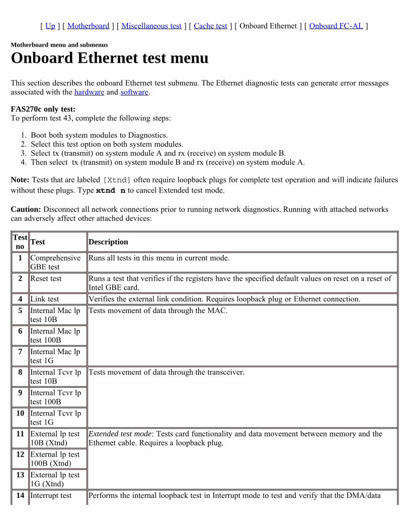
Onboard Ethernet test menuThis section describes the onboard Ethernet test submenu. The Ethernet diagnostic tests can generate error messagesassociated with the hardware and software.
FAS270c only test:To perform test 43, complete the following steps:
1. Boot both system modules to Diagnostics.2. Select this test option on both system modules.3. Select tx (transmit) on system module A and rx (receive) on system module B.4. Then select tx (transmit) on system module B and rx (receive) on system module A.
Note: Tests that are labeled [Xtnd] often require loopback plugs for complete test operation and will indicate failureswithout these plugs. Type xtnd n to cancel Extended test mode.
Caution: Disconnect all network connections prior to running network diagnostics. Running with attached networkscan adversely affect other attached devices:
Testno Test Description
1 ComprehensiveGBE test
Runs all tests in this menu in current mode.
2 Reset test Runs a test that verifies if the registers have the specified default values on reset on a reset ofIntel GBE card.
4 Link test Verifies the external link condition. Requires loopback plug or Ethernet connection.5 Internal Mac lp
test 10BTests movement of data through the MAC.
6 Internal Mac lptest 100B
7 Internal Mac lptest 1G
8 Internal Tcvr lptest 10B
Tests movement of data through the transceiver.
9 Internal Tcvr lptest 100B
10 Internal Tcvr lptest 1G
11 External lp test10B (Xtnd)
Extended test mode: Tests card functionality and data movement between memory and theEthernet cable. Requires a loopback plug.
12 External lp test100B (Xtnd)
13 External lp test1G (Xtnd)
14 Interrupt test Performs the internal loopback test in Interrupt mode to test and verify that the DMA/data
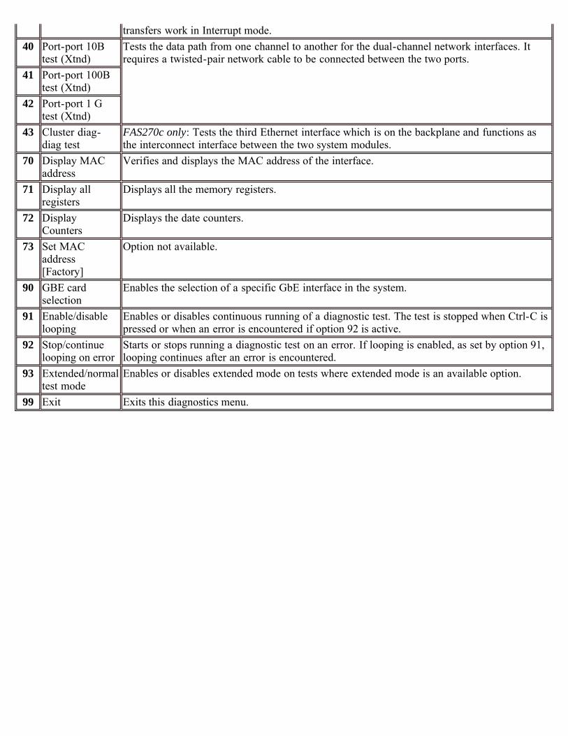
transfers work in Interrupt mode.40 Port-port 10B
test (Xtnd)Tests the data path from one channel to another for the dual-channel network interfaces. Itrequires a twisted-pair network cable to be connected between the two ports.
41 Port-port 100Btest (Xtnd)
42 Port-port 1 Gtest (Xtnd)
43 Cluster diag-diag test
FAS270c only: Tests the third Ethernet interface which is on the backplane and functions asthe interconnect interface between the two system modules.
70 Display MACaddress
Verifies and displays the MAC address of the interface.
71 Display allregisters
Displays all the memory registers.
72 DisplayCounters
Displays the date counters.
73 Set MACaddress[Factory]
Option not available.
90 GBE cardselection
Enables the selection of a specific GbE interface in the system.
91 Enable/disablelooping
Enables or disables continuous running of a diagnostic test. The test is stopped when Ctrl-C ispressed or when an error is encountered if option 92 is active.
92 Stop/continuelooping on error
Starts or stops running a diagnostic test on an error. If looping is enabled, as set by option 91,looping continues after an error is encountered.
93 Extended/normaltest mode
Enables or disables extended mode on tests where extended mode is an available option.
99 Exit Exits this diagnostics menu.
[ Up ] [ Motherboard ] [ Miscellaneous test ] [ Cache test ] [ Onboard Ethernet ] [ Onboard FC-AL ]
Motherboard menu and submenus
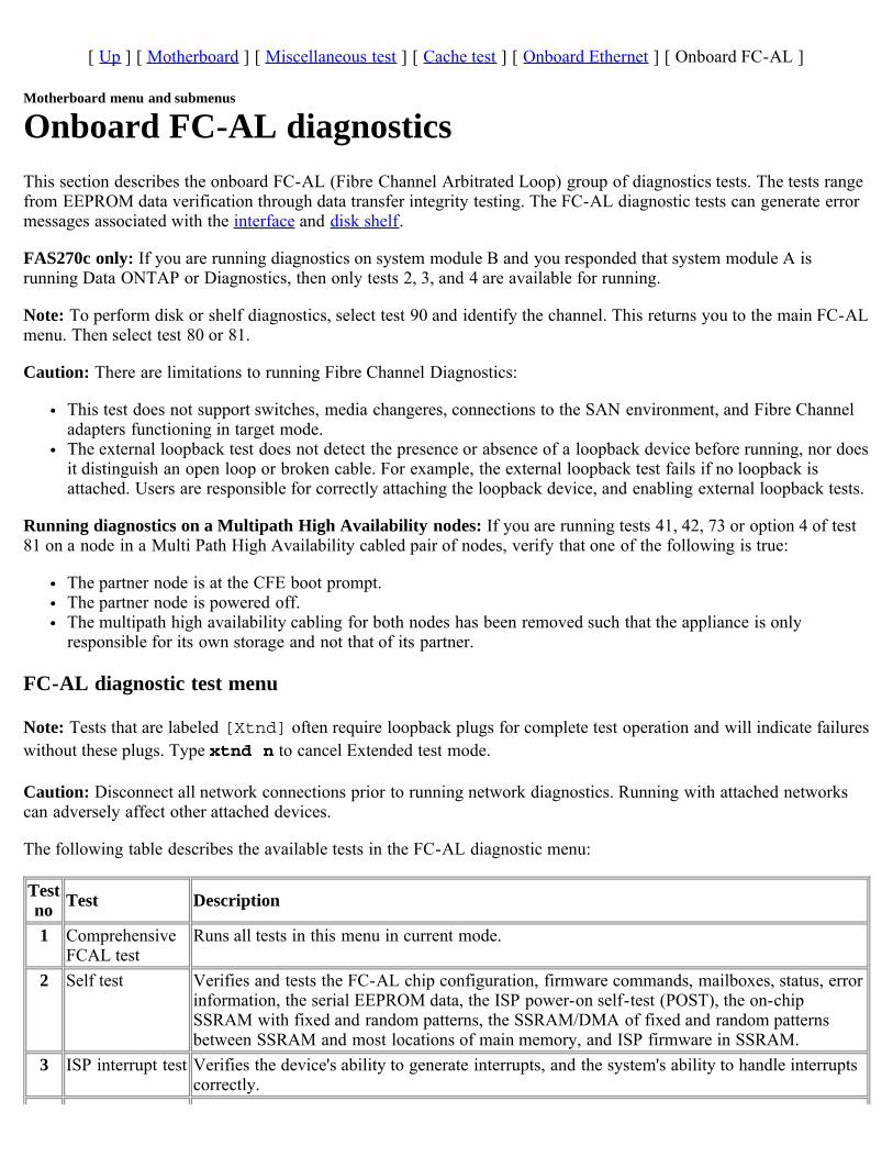
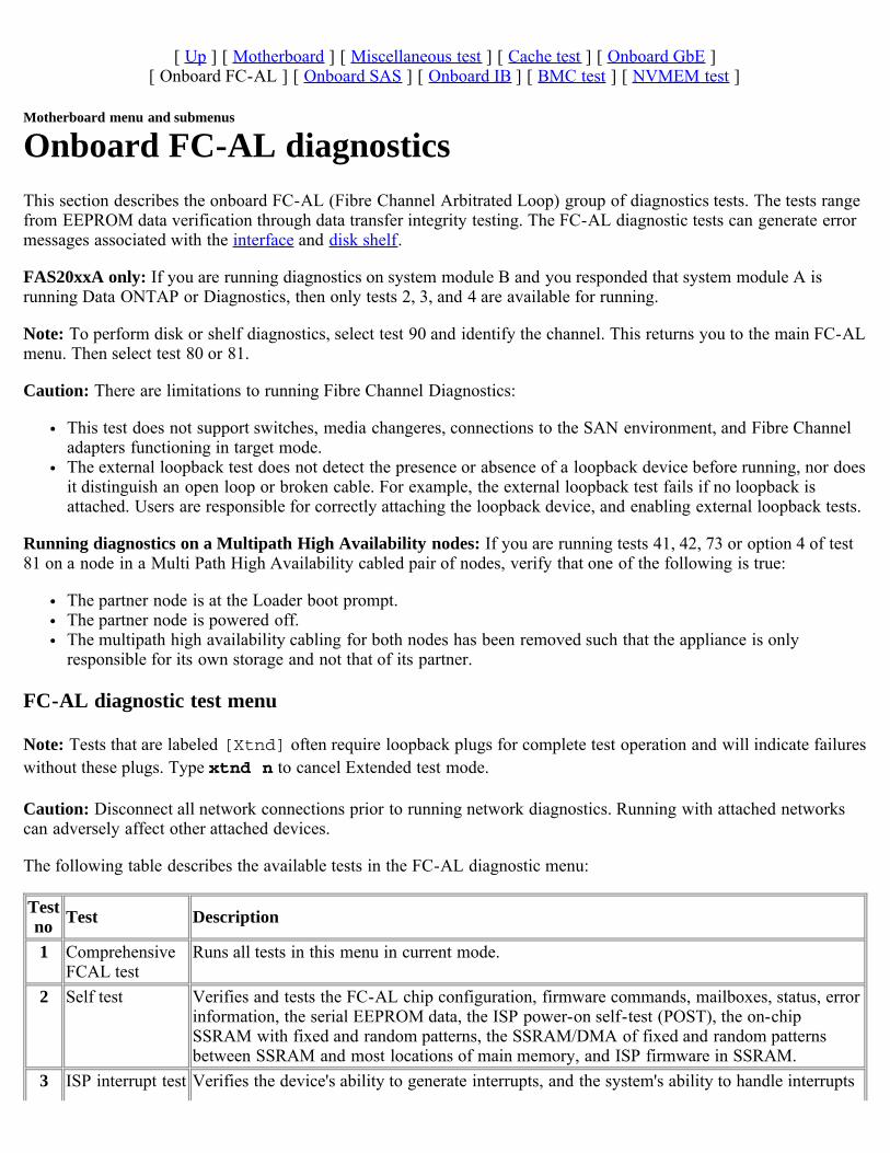
Onboard FC-AL diagnosticsThis section describes the onboard FC-AL (Fibre Channel Arbitrated Loop) group of diagnostics tests. The tests rangefrom EEPROM data verification through data transfer integrity testing. The FC-AL diagnostic tests can generate errormessages associated with the interface and disk shelf.
FAS270c only: If you are running diagnostics on system module B and you responded that system module A isrunning Data ONTAP or Diagnostics, then only tests 2, 3, and 4 are available for running.
Note: To perform disk or shelf diagnostics, select test 90 and identify the channel. This returns you to the main FC-ALmenu. Then select test 80 or 81.
Caution: There are limitations to running Fibre Channel Diagnostics:
This test does not support switches, media changeres, connections to the SAN environment, and Fibre Channeladapters functioning in target mode.The external loopback test does not detect the presence or absence of a loopback device before running, nor doesit distinguish an open loop or broken cable. For example, the external loopback test fails if no loopback isattached. Users are responsible for correctly attaching the loopback device, and enabling external loopback tests.
Running diagnostics on a Multipath High Availability nodes: If you are running tests 41, 42, 73 or option 4 of test81 on a node in a Multi Path High Availability cabled pair of nodes, verify that one of the following is true:
The partner node is at the CFE boot prompt.The partner node is powered off.The multipath high availability cabling for both nodes has been removed such that the appliance is onlyresponsible for its own storage and not that of its partner.
FC-AL diagnostic test menu
Note: Tests that are labeled [Xtnd] often require loopback plugs for complete test operation and will indicate failureswithout these plugs. Type xtnd n to cancel Extended test mode.
Caution: Disconnect all network connections prior to running network diagnostics. Running with attached networkscan adversely affect other attached devices.
The following table describes the available tests in the FC-AL diagnostic menu:
Testno Test Description
1 ComprehensiveFCAL test
Runs all tests in this menu in current mode.
2 Self test Verifies and tests the FC-AL chip configuration, firmware commands, mailboxes, status, errorinformation, the serial EEPROM data, the ISP power-on self-test (POST), the on-chipSSRAM with fixed and random patterns, the SSRAM/DMA of fixed and random patternsbetween SSRAM and most locations of main memory, and ISP firmware in SSRAM.
3 ISP interrupt test Verifies the device's ability to generate interrupts, and the system's ability to handle interruptscorrectly.
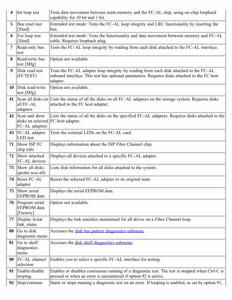
4 Int loop test Tests data movement between main memory and the FC-AL chip, using on-chip loopbackcapability for 10 bit and 1 bit.
5 Bus reset test[Xtnd]
Extended test mode: Tests the FC-AL loop integrity and LRC functionality by resetting thebus.
6 Ext loop test[Xtnd]
Extended test mode: Tests the functionality and data movement between memory and FC-ALcable. Requires loopback plug.
7 Read-only bustest
Tests the FC-AL loop integrity by reading from each disk attached to the FC-AL interface.
8 Read/write bustest [Mfg]
Option not available.
9 Disk read test(FCTEST)
Tests the FC-AL adapter loop integrity by reading from each disk attached to the FC-ALonboard interface. This test has optional parameters. Requires disks attached to the FC hostadapter.
10 Disk read/writetest [Mfg]
Option not available.
41 Scan all disks onall FC-ALadapters
Lists the status of all the disks on all FC-AL adapters on the storage system. Requires disksattached to the FC host adapter.
42 Scan and showdisks on selectedFC-AL adapters
Lists the status of all the disks on the specified FC-AL adapters. Requires disks attached to theFC host adapter.
43 FC-AL adapterLED test
Tests the external LEDs on the FC-AL card.
71 Show ISP FCchip info
Displays information about the ISP Fibre Channel chip.
72 Show attachedFC-AL devices
Displays all devices attached to a specific FC-AL adapter.
73 Show all disks(probe-scsi-all)
Lists disk information for all disks attached to the system.
74 Reset FC-ALadapter
Resets the selected FC-AL adapter to its original state.
75 Show serialEEPROM data
Displays the serial EEPROM data.
76 Program serialEEPROM data[Factory]
Option not available.
77 Display fcstatlink_status
Displays the link statistics maintained for all drives on a Fibre Channel loop.
80 Go to diskdiagnostic menu
Accesses the disk bus pattern diagnostics submenu.
81 Go to shelfdiagnosticsmenu
Accesses the disk shelf diagnostics submenu.
90 FC-AL channelselection
Enables you to select a specific FC-AL interface for testing.
91 Enable/disablelooping
Enables or disables continuous running of a diagnostic test. The test is stopped when Ctrl-C ispressed or when an error is encountered if option 92 is active.
92 Stop/continue Starts or stops running a diagnostic test on an error. If looping is enabled, as set by option 91,

looping on error looping continues after an error is encountered.93 Extended/normal
test modeEnables or disables extended mode on tests where extended mode is an available option.
99 Exit Exits this diagnostics menu.
[ Up ] [ Disk diagnostics ] [ Disk shelf diagnostics ]
Card diagnostics
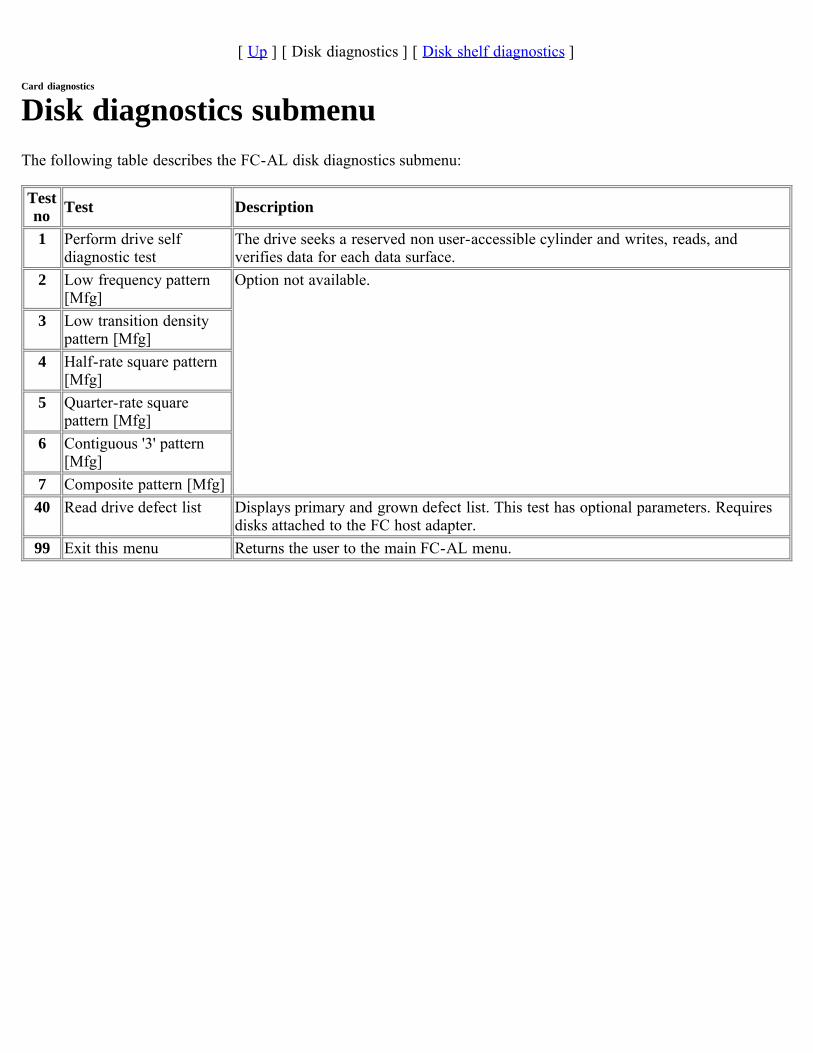
Disk diagnostics submenuThe following table describes the FC-AL disk diagnostics submenu:
Testno Test Description
1 Perform drive selfdiagnostic test
The drive seeks a reserved non user-accessible cylinder and writes, reads, andverifies data for each data surface.
2 Low frequency pattern[Mfg]
Option not available.
3 Low transition densitypattern [Mfg]
4 Half-rate square pattern[Mfg]
5 Quarter-rate squarepattern [Mfg]
6 Contiguous '3' pattern[Mfg]
7 Composite pattern [Mfg]40 Read drive defect list Displays primary and grown defect list. This test has optional parameters. Requires
disks attached to the FC host adapter.99 Exit this menu Returns the user to the main FC-AL menu.

[ Up ] [ Disk diagnostics ] [ Disk shelf diagnostics ]
Disk shelf diagnostics submenuThe following table describes the disk shelf diagnostics submenu for the FC-AL interface.
Note: Tests that are labeled [Xtnd] often require loopback plugs for complete test operation and indicate failureswithout these plugs.
Caution: Do not run [Xtnd] mode diagnostics on network adapters with live network connections. Disconnect allnetwork connections prior to running network diagnostics in [Xtnd] mode. Running with attached networks canadversely affect other attached devices. Enter xtnd n to cancel Extended test mode:
Testno Test Description
1 Turn shelf LED on Turns on the drive LEDs.2 Turn shelf LED off Turns off the drive LEDs.3 Get trunk information Option not available.4 Get shelf drive map Displays the list of drives on target FC-AL interface.5 Get shelf environment
informationDisplays the environmental parameters on the target FC-AL interface.
6 Check SES temperature sensors Checks SES temperature sensors against threshold value.7 Check SES Fans Checks SES fan status.8 Check SES power supply Checks SES power supply status.9 Check SES ESH (HUB) Option not available.
10 Check all SES elements Check status of all SES elements in the shelf.11 Loop integrity/LRC test [Xtnd] Extended test mode: Tests the FC-AL loop integrity and LRC functionality.12 Show HUB status Option not available.70 Display sector size for FC-AL
devicesDisplays the sector size for the drives on the disk shelves.
93 Extended/normal test mode Enables or disables extended mode on tests where extended mode is anavailable option.
99 Exit this menu Returns the user to the main FC-AL menu.
Diagnostics Menus - Motherboard
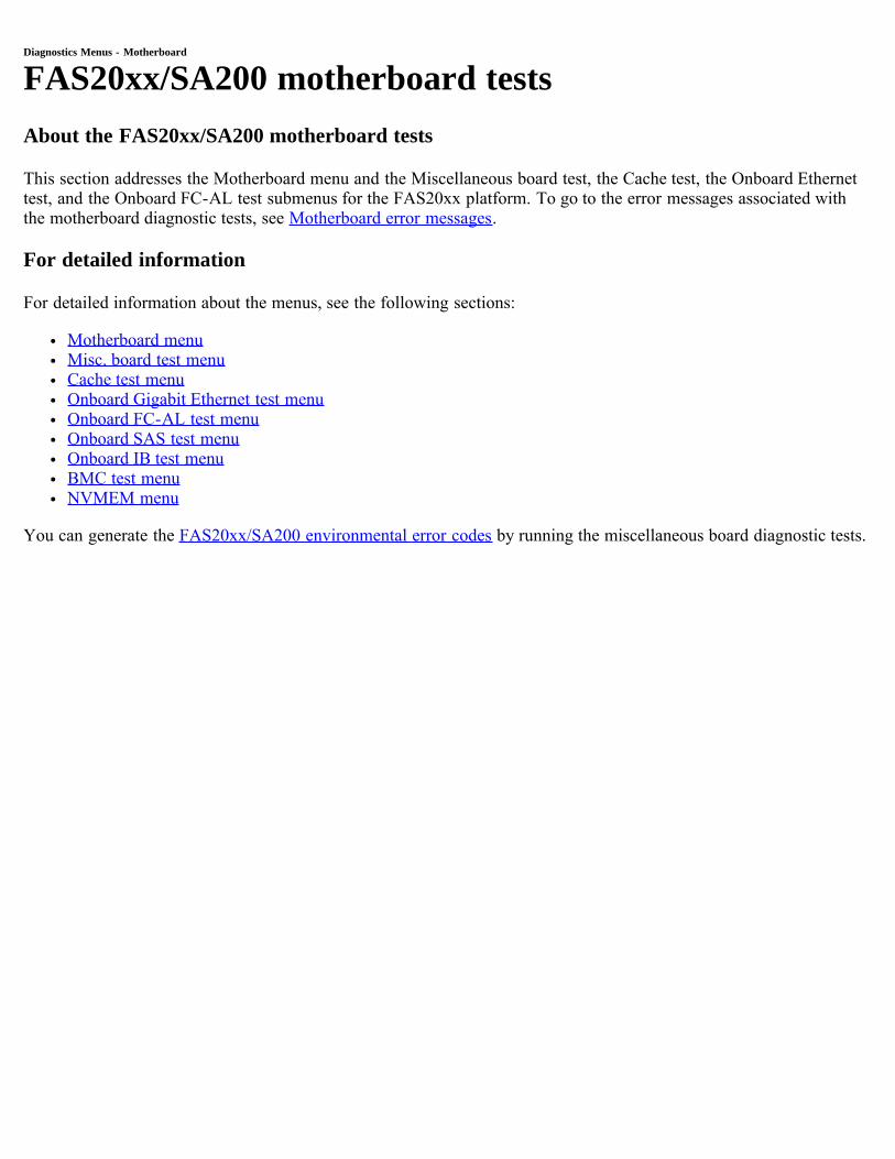
FAS20xx/SA200 motherboard testsAbout the FAS20xx/SA200 motherboard tests
This section addresses the Motherboard menu and the Miscellaneous board test, the Cache test, the Onboard Ethernettest, and the Onboard FC-AL test submenus for the FAS20xx platform. To go to the error messages associated withthe motherboard diagnostic tests, see Motherboard error messages.
For detailed information
For detailed information about the menus, see the following sections:
Motherboard menuMisc. board test menuCache test menuOnboard Gigabit Ethernet test menuOnboard FC-AL test menuOnboard SAS test menuOnboard IB test menuBMC test menuNVMEM menu
You can generate the FAS20xx/SA200 environmental error codes by running the miscellaneous board diagnostic tests.
[ Up ] [ Motherboard ] [ Miscellaneous test ] [ Cache test ] [ Onboard GbE ][ Onboard FC-AL ] [ Onboard SAS ] [ Onboard IB ] [ BMC test ] [ NVMEM test ]
Motherboard menu and submenus
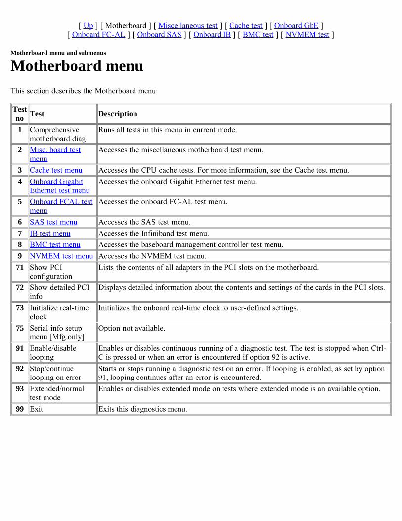
Motherboard menuThis section describes the Motherboard menu:
Testno Test Description
1 Comprehensivemotherboard diag
Runs all tests in this menu in current mode.
2 Misc. board testmenu
Accesses the miscellaneous motherboard test menu.
3 Cache test menu Accesses the CPU cache tests. For more information, see the Cache test menu.4 Onboard Gigabit
Ethernet test menuAccesses the onboard Gigabit Ethernet test menu.
5 Onboard FCAL testmenu
Accesses the onboard FC-AL test menu.
6 SAS test menu Accesses the SAS test menu.7 IB test menu Accesses the Infiniband test menu.8 BMC test menu Accesses the baseboard management controller test menu.9 NVMEM test menu Accesses the NVMEM test menu.71 Show PCI
configurationLists the contents of all adapters in the PCI slots on the motherboard.
72 Show detailed PCIinfo
Displays detailed information about the contents and settings of the cards in the PCI slots.
73 Initialize real-timeclock
Initializes the onboard real-time clock to user-defined settings.
75 Serial info setupmenu [Mfg only]
Option not available.
91 Enable/disablelooping
Enables or disables continuous running of a diagnostic test. The test is stopped when Ctrl-C is pressed or when an error is encountered if option 92 is active.
92 Stop/continuelooping on error
Starts or stops running a diagnostic test on an error. If looping is enabled, as set by option91, looping continues after an error is encountered.
93 Extended/normaltest mode
Enables or disables extended mode on tests where extended mode is an available option.
99 Exit Exits this diagnostics menu.
[ Up ] [ Motherboard ] [ Miscellaneous test ] [ Cache test ] [ Onboard GbE ][ Onboard FC-AL ] [ Onboard SAS ] [ Onboard IB ] [ BMC test ] [ NVMEM test ]
Motherboard menu and submenus
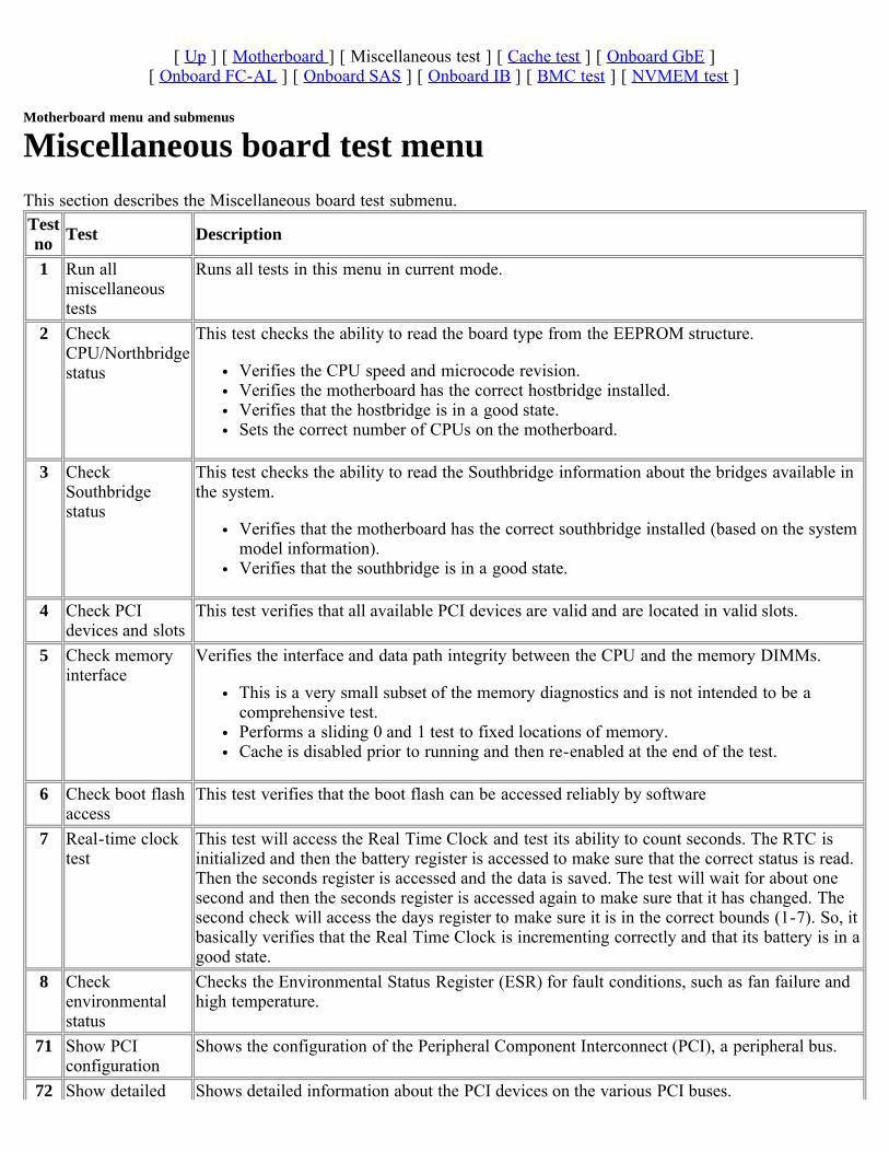
Miscellaneous board test menuThis section describes the Miscellaneous board test submenu. Testno Test Description
1 Run allmiscellaneoustests
Runs all tests in this menu in current mode.
2 CheckCPU/Northbridgestatus
This test checks the ability to read the board type from the EEPROM structure.
Verifies the CPU speed and microcode revision.Verifies the motherboard has the correct hostbridge installed.Verifies that the hostbridge is in a good state.Sets the correct number of CPUs on the motherboard.
3 CheckSouthbridgestatus
This test checks the ability to read the Southbridge information about the bridges available inthe system.
Verifies that the motherboard has the correct southbridge installed (based on the systemmodel information).Verifies that the southbridge is in a good state.
4 Check PCIdevices and slots
This test verifies that all available PCI devices are valid and are located in valid slots.
5 Check memoryinterface
Verifies the interface and data path integrity between the CPU and the memory DIMMs.
This is a very small subset of the memory diagnostics and is not intended to be acomprehensive test.Performs a sliding 0 and 1 test to fixed locations of memory.Cache is disabled prior to running and then re-enabled at the end of the test.
6 Check boot flashaccess
This test verifies that the boot flash can be accessed reliably by software
7 Real-time clocktest
This test will access the Real Time Clock and test its ability to count seconds. The RTC isinitialized and then the battery register is accessed to make sure that the correct status is read.Then the seconds register is accessed and the data is saved. The test will wait for about onesecond and then the seconds register is accessed again to make sure that it has changed. Thesecond check will access the days register to make sure it is in the correct bounds (1-7). So, itbasically verifies that the Real Time Clock is incrementing correctly and that its battery is in agood state.
8 Checkenvironmentalstatus
Checks the Environmental Status Register (ESR) for fault conditions, such as fan failure andhigh temperature.
71 Show PCIconfiguration
Shows the configuration of the Peripheral Component Interconnect (PCI), a peripheral bus.
72 Show detailed Shows detailed information about the PCI devices on the various PCI buses.
PCI info73 Initialize real-
time clockInitializes the battery powered, real-time clock.
91 Enable/disablelooping
Enables or disables continuous running of a diagnostic test. The test is stopped when Ctrl-C ispressed or when an error is encountered if option 92 is active.
92 Stop/continuelooping on error
Starts or stops running a diagnostic test on an error. If looping is enabled, as set by option 91,looping continues after an error is encountered.
93 Extended/normaltest mode
Enables or disables extended mode on tests where extended mode is an available option.
99 Exit Exits this diagnostics menu.
[ Up ] [ Motherboard ] [ Miscellaneous test ] [ Cache test ] [ Onboard GbE ][ Onboard FC-AL ] [ Onboard SAS ] [ Onboard IB ] [ BMC test ] [ NVMEM test ]
Motherboard menu and submenus
Cache test menuThe section describes the Cache test submenu.Testno Test Description
1 Comprehensivecache test
Runs all tests in this menu in current mode.
2 Cache walkingdata bits test
This test performs a walking 1 in a field of zeroes and a walking 0 in a field of ones. This testis repeated at each 8K "bank" boundary.
This test is intended to verify data lines within L2 cache and to/from/within each DIMM bank.Expected to detect hard faults such as shorts and opens.
3 Cache stuck-atfaults test
Scans through all cache locations, checking for stuck bits (0 or 1).
4 Cache randomread/write test
This test is intended to access chunks of memory within an individual DIMM as rapidly aspossible to stress the DIMM. Block size is chosen to be large enough to force cache collisions.Operation (read/write) is chosen randomly, along with the block, so this test causes someunique stressing of the memory system.
5 Cache randomdata test
This test is intended to verify all locations of SRAM cache and is expected to detect allcommon SRAM failures such as stuck cells or cell coupling. Intermittent errors may also beencountered, caused by noise or margin problems. Parity and ECC are stressed by the randompatterns used.
6 Cache randomaddress test
This test is intended to verify overall operation of L2 cache, with particular emphasis on noise,signal coupling and simultaneous switching problems. Detection of intermittent and marginproblems is also expected.
7 Cache spill test Tests the cache interface to main memory. Causes cache flush and reload. Provides excellenttest of cache management logic.
8 Cache tag test Tests the cache tags by reading random addresses.9 Cache MP test Available on multiprocessor systems only.91 Enable/disable
loopingEnables or disables continuous running of a diagnostic test. The test is stopped when Ctrl-C ispressed or when an error is encountered if option 92 is active.
92 Stop/continuelooping onerror
Starts or stops running a diagnostic test on an error. If looping is enabled, as set by option 91,looping continues after an error is encountered.
99 Exit Exits this diagnostics menu.
[ Up ] [ Motherboard ] [ Miscellaneous test ] [ Cache test ] [ Onboard GbE ][ Onboard FC-AL ] [ Onboard SAS ] [ Onboard IB ] [ BMC test ] [ NVMEM test ]
Motherboard menu and submenus
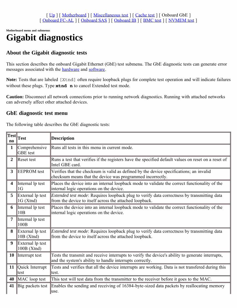
Gigabit diagnosticsAbout the Gigabit diagnostic tests
This section describes the onboard Gigabit Ethernet (GbE) test submenu. The GbE diagnostic tests can generate errormessages associated with the hardware and software.
Note: Tests that are labeled [Xtnd] often require loopback plugs for complete test operation and will indicate failureswithout these plugs. Type xtnd n to cancel Extended test mode.
Caution: Disconnect all network connections prior to running network diagnostics. Running with attached networkscan adversely affect other attached devices.
GbE diagnostic test menu
The following table describes the GbE diagnostic tests:
Testno Test Description
1 ComprehensiveGBE test
Runs all tests in this menu in current mode.
2 Reset test Runs a test that verifies if the registers have the specified default values on reset on a reset ofIntel GBE card.
3 EEPROM test Verifies that the checksum is valid as defined by the device specifications; an invalidchecksum means that the device was programmed incorrectly.
4 Internal lp test1G
Places the device into an internal loopback mode to validate the correct functionality of theinternal logic operations on the device.
5 External lp test1G (Xtnd)
Extended test mode: Requires loopback plug to verify data correctness by transmitting datafrom the device to itself across the attached loopback.
6 Internal lp test10B
Places the device into an internal loopback mode to validate the correct functionality of theinternal logic operations on the device.
7 Internal lp test100B
8 External lp test10B (Xtnd)
Extended test mode: Requires loopback plug to verify data correctness by transmitting datafrom the device to itself across the attached loopback.
9 External lp test100B (Xtnd)
10 Interrupt test Tests the transmit and receive interrupts to verify the device's ability to generate interrupts,and the system's ability to handle interrupts correctly.
11 Quick Interrupttest
Tests and verifies that all the device interrupts are working. Data is not transfered during thistest.
40 MAC loop test This test will test data from the transmitter to the receiver before it goes to the MAC.41 Big packets test Enables the sending and receiving of 16384-byte-sized data packets by reallocating memory
use.
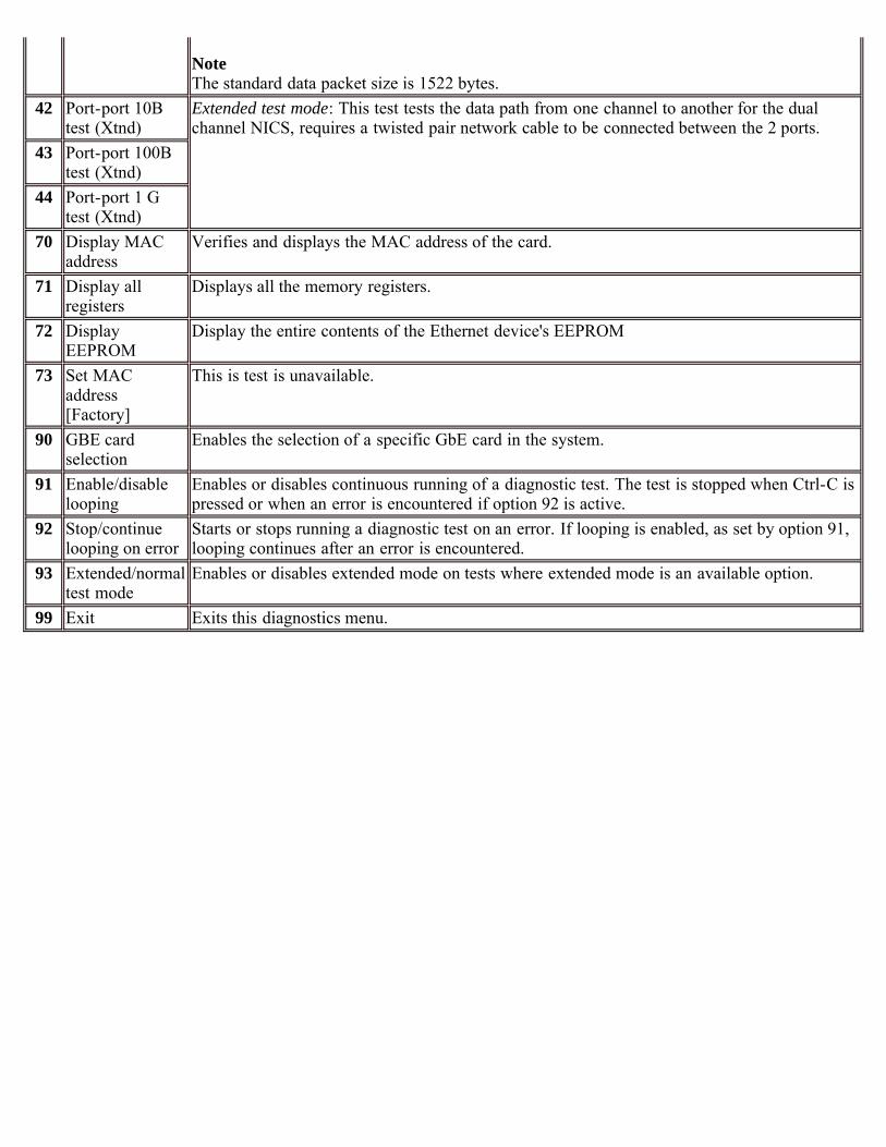
NoteThe standard data packet size is 1522 bytes.
42 Port-port 10Btest (Xtnd)
Extended test mode: This test tests the data path from one channel to another for the dualchannel NICS, requires a twisted pair network cable to be connected between the 2 ports.
43 Port-port 100Btest (Xtnd)
44 Port-port 1 Gtest (Xtnd)
70 Display MACaddress
Verifies and displays the MAC address of the card.
71 Display allregisters
Displays all the memory registers.
72 DisplayEEPROM
Display the entire contents of the Ethernet device's EEPROM
73 Set MACaddress[Factory]
This is test is unavailable.
90 GBE cardselection
Enables the selection of a specific GbE card in the system.
91 Enable/disablelooping
Enables or disables continuous running of a diagnostic test. The test is stopped when Ctrl-C ispressed or when an error is encountered if option 92 is active.
92 Stop/continuelooping on error
Starts or stops running a diagnostic test on an error. If looping is enabled, as set by option 91,looping continues after an error is encountered.
93 Extended/normaltest mode
Enables or disables extended mode on tests where extended mode is an available option.
99 Exit Exits this diagnostics menu.
[ Up ] [ Motherboard ] [ Miscellaneous test ] [ Cache test ] [ Onboard GbE ][ Onboard FC-AL ] [ Onboard SAS ] [ Onboard IB ] [ BMC test ] [ NVMEM test ]
Motherboard menu and submenus
Onboard FC-AL diagnosticsThis section describes the onboard FC-AL (Fibre Channel Arbitrated Loop) group of diagnostics tests. The tests rangefrom EEPROM data verification through data transfer integrity testing. The FC-AL diagnostic tests can generate errormessages associated with the interface and disk shelf.
FAS20xxA only: If you are running diagnostics on system module B and you responded that system module A isrunning Data ONTAP or Diagnostics, then only tests 2, 3, and 4 are available for running.
Note: To perform disk or shelf diagnostics, select test 90 and identify the channel. This returns you to the main FC-ALmenu. Then select test 80 or 81.
Caution: There are limitations to running Fibre Channel Diagnostics:
This test does not support switches, media changeres, connections to the SAN environment, and Fibre Channeladapters functioning in target mode.The external loopback test does not detect the presence or absence of a loopback device before running, nor doesit distinguish an open loop or broken cable. For example, the external loopback test fails if no loopback isattached. Users are responsible for correctly attaching the loopback device, and enabling external loopback tests.
Running diagnostics on a Multipath High Availability nodes: If you are running tests 41, 42, 73 or option 4 of test81 on a node in a Multi Path High Availability cabled pair of nodes, verify that one of the following is true:
The partner node is at the Loader boot prompt.The partner node is powered off.The multipath high availability cabling for both nodes has been removed such that the appliance is onlyresponsible for its own storage and not that of its partner.
FC-AL diagnostic test menu
Note: Tests that are labeled [Xtnd] often require loopback plugs for complete test operation and will indicate failureswithout these plugs. Type xtnd n to cancel Extended test mode.
Caution: Disconnect all network connections prior to running network diagnostics. Running with attached networkscan adversely affect other attached devices.
The following table describes the available tests in the FC-AL diagnostic menu:
Testno Test Description
1 ComprehensiveFCAL test
Runs all tests in this menu in current mode.
2 Self test Verifies and tests the FC-AL chip configuration, firmware commands, mailboxes, status, errorinformation, the serial EEPROM data, the ISP power-on self-test (POST), the on-chipSSRAM with fixed and random patterns, the SSRAM/DMA of fixed and random patternsbetween SSRAM and most locations of main memory, and ISP firmware in SSRAM.
3 ISP interrupt test Verifies the device's ability to generate interrupts, and the system's ability to handle interrupts
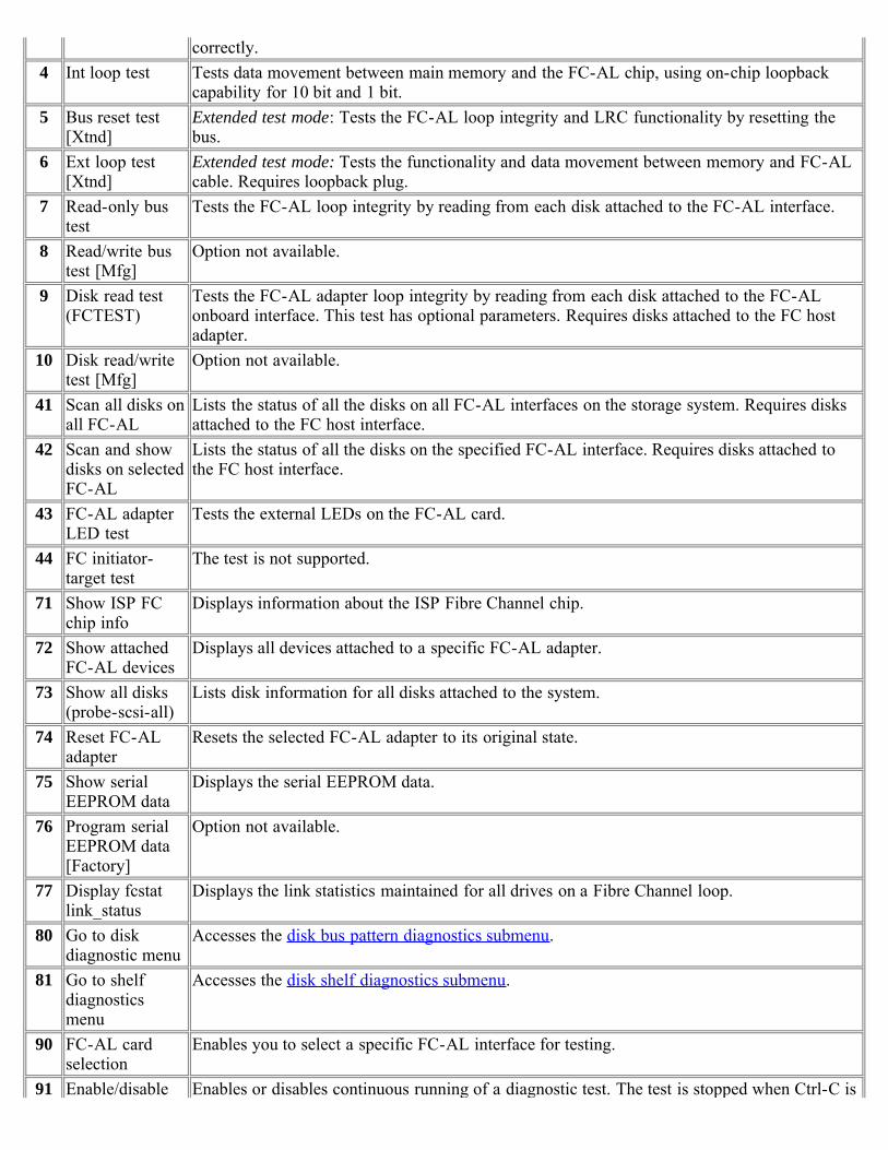
correctly.4 Int loop test Tests data movement between main memory and the FC-AL chip, using on-chip loopback
capability for 10 bit and 1 bit.5 Bus reset test
[Xtnd]Extended test mode: Tests the FC-AL loop integrity and LRC functionality by resetting thebus.
6 Ext loop test[Xtnd]
Extended test mode: Tests the functionality and data movement between memory and FC-ALcable. Requires loopback plug.
7 Read-only bustest
Tests the FC-AL loop integrity by reading from each disk attached to the FC-AL interface.
8 Read/write bustest [Mfg]
Option not available.
9 Disk read test(FCTEST)
Tests the FC-AL adapter loop integrity by reading from each disk attached to the FC-ALonboard interface. This test has optional parameters. Requires disks attached to the FC hostadapter.
10 Disk read/writetest [Mfg]
Option not available.
41 Scan all disks onall FC-AL
Lists the status of all the disks on all FC-AL interfaces on the storage system. Requires disksattached to the FC host interface.
42 Scan and showdisks on selectedFC-AL
Lists the status of all the disks on the specified FC-AL interface. Requires disks attached tothe FC host interface.
43 FC-AL adapterLED test
Tests the external LEDs on the FC-AL card.
44 FC initiator-target test
The test is not supported.
71 Show ISP FCchip info
Displays information about the ISP Fibre Channel chip.
72 Show attachedFC-AL devices
Displays all devices attached to a specific FC-AL adapter.
73 Show all disks(probe-scsi-all)
Lists disk information for all disks attached to the system.
74 Reset FC-ALadapter
Resets the selected FC-AL adapter to its original state.
75 Show serialEEPROM data
Displays the serial EEPROM data.
76 Program serialEEPROM data[Factory]
Option not available.
77 Display fcstatlink_status
Displays the link statistics maintained for all drives on a Fibre Channel loop.
80 Go to diskdiagnostic menu
Accesses the disk bus pattern diagnostics submenu.
81 Go to shelfdiagnosticsmenu
Accesses the disk shelf diagnostics submenu.
90 FC-AL cardselection
Enables you to select a specific FC-AL interface for testing.
91 Enable/disable Enables or disables continuous running of a diagnostic test. The test is stopped when Ctrl-C is

looping pressed or when an error is encountered if option 92 is active.92 Stop/continue
looping on errorStarts or stops running a diagnostic test on an error. If looping is enabled, as set by option 91,looping continues after an error is encountered.
93 Extended/normaltest mode
Enables or disables extended mode on tests where extended mode is an available option.
99 Exit Exits this diagnostics menu.
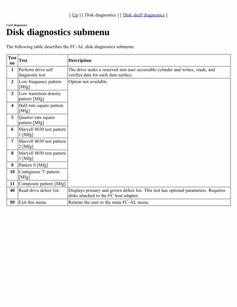
[ Up ] [ Disk diagnostics ] [ Disk shelf diagnostics ]
Card diagnostics
Disk diagnostics submenuThe following table describes the FC-AL disk diagnostics submenu:
Testno Test Description
1 Perform drive selfdiagnostic test
The drive seeks a reserved non user-accessible cylinder and writes, reads, andverifies data for each data surface.
2 Low frequency pattern[Mfg]
Option not available.
3 Low transition densitypattern [Mfg]
4 Half-rate square pattern[Mfg]
5 Quarter-rate squarepattern [Mfg]
6 Marvell 8030 test pattern1 [Mfg]
7 Marvell 8030 test pattern2 [Mfg]
8 Marvell 8030 test pattern3 [Mfg]
9 Pattern 0 [Mfg]10 Contiguous '3' pattern
[Mfg]11 Composite pattern [Mfg]40 Read drive defect list Displays primary and grown defect list. This test has optional parameters. Requires
disks attached to the FC host adapter.99 Exit this menu Returns the user to the main FC-AL menu.

[ Up ] [ Disk diagnostics ] [ Disk shelf diagnostics ]
Disk shelf diagnostics submenuThe following table describes the disk shelf diagnostics submenu for the FC-AL interface.
Note: Tests that are labeled [Xtnd] often require loopback plugs for complete test operation and indicate failureswithout these plugs.
Caution: Do not run [Xtnd] mode diagnostics on network adapters with live network connections. Disconnect allnetwork connections prior to running network diagnostics in [Xtnd] mode. Running with attached networks canadversely affect other attached devices. Enter xtnd n to cancel Extended test mode:
Testno Test Description
1 Check LED Turns on the drive LEDs.2 Get trunk information Displays the list of disk shelves and their firmware revisions on the target FC-
AL card.3 Get shelf drive map Displays the list of drives on the disk shelves of the target FC-AL card.4 Get shelf environment
informationDisplays the environmental parameters for the disk shelves on the target FC-AL card.
5 Check SES temperaturesensors
Check SES temperature sensors against threshold value.
6 Check SES FANs Check SES fan status.7 Check SES Power Supply Check SES Power Supply status.8 Check SES ESH (HUB) Option not available.9 Check all SES elements Check status of all SES elements in the shelf.10 Loop integrity/LRC test
[Xtnd]Option not available.
11 Show HUB status12 Show Expander Status Displays the expander status.70 Display disk sector size Displays the sector size for the drives on the disk shelves.93 Extended/normal test mode Enables or disables extended mode on tests where extended mode is an
available option.99 Exit this menu Returns the user to the main FC-AL menu.
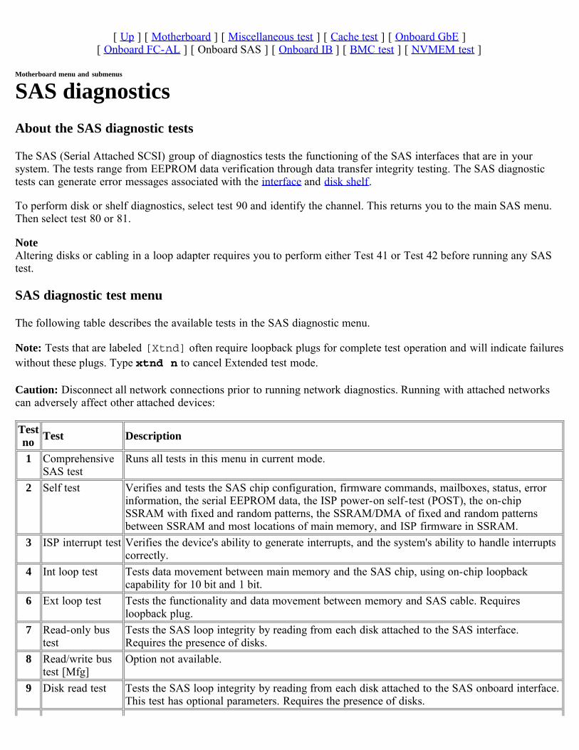
[ Up ] [ Motherboard ] [ Miscellaneous test ] [ Cache test ] [ Onboard GbE ][ Onboard FC-AL ] [ Onboard SAS ] [ Onboard IB ] [ BMC test ] [ NVMEM test ]
Motherboard menu and submenus
SAS diagnosticsAbout the SAS diagnostic tests
The SAS (Serial Attached SCSI) group of diagnostics tests the functioning of the SAS interfaces that are in yoursystem. The tests range from EEPROM data verification through data transfer integrity testing. The SAS diagnostictests can generate error messages associated with the interface and disk shelf.
To perform disk or shelf diagnostics, select test 90 and identify the channel. This returns you to the main SAS menu.Then select test 80 or 81.
NoteAltering disks or cabling in a loop adapter requires you to perform either Test 41 or Test 42 before running any SAStest.
SAS diagnostic test menu
The following table describes the available tests in the SAS diagnostic menu.
Note: Tests that are labeled [Xtnd] often require loopback plugs for complete test operation and will indicate failureswithout these plugs. Type xtnd n to cancel Extended test mode.
Caution: Disconnect all network connections prior to running network diagnostics. Running with attached networkscan adversely affect other attached devices:
Testno Test Description
1 ComprehensiveSAS test
Runs all tests in this menu in current mode.
2 Self test Verifies and tests the SAS chip configuration, firmware commands, mailboxes, status, errorinformation, the serial EEPROM data, the ISP power-on self-test (POST), the on-chipSSRAM with fixed and random patterns, the SSRAM/DMA of fixed and random patternsbetween SSRAM and most locations of main memory, and ISP firmware in SSRAM.
3 ISP interrupt test Verifies the device's ability to generate interrupts, and the system's ability to handle interruptscorrectly.
4 Int loop test Tests data movement between main memory and the SAS chip, using on-chip loopbackcapability for 10 bit and 1 bit.
6 Ext loop test Tests the functionality and data movement between memory and SAS cable. Requiresloopback plug.
7 Read-only bustest
Tests the SAS loop integrity by reading from each disk attached to the SAS interface.Requires the presence of disks.
8 Read/write bustest [Mfg]
Option not available.
9 Disk read test Tests the SAS loop integrity by reading from each disk attached to the SAS onboard interface.This test has optional parameters. Requires the presence of disks.
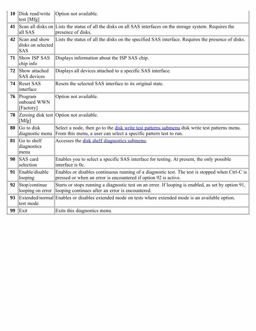
10 Disk read/writetest [Mfg]
Option not available.
41 Scan all disks onall SAS
Lists the status of all the disks on all SAS interfaces on the storage system. Requires thepresence of disks.
42 Scan and showdisks on selectedSAS
Lists the status of all the disks on the specified SAS interface. Requires the presence of disks.
71 Show ISP SASchip info
Displays information about the ISP SAS chip.
72 Show attachedSAS devices
Displays all devices attached to a specific SAS interface.
74 Reset SASinterface
Resets the selected SAS interface to its original state.
76 Programonboard WWN[Factory]
Option not available.
78 Zeroing disk test[Mfg]
Option not available.
80 Go to diskdiagnostic menu
Select a node, then go to the disk write test patterns submenu disk write test patterns menu.From this menu, a user can select a specific pattern test to run.
81 Go to shelfdiagnosticsmenu
Accesses the disk shelf diagnostics submenu.
90 SAS cardselection
Enables you to select a specific SAS interface for testing. At present, the only possibleinterface is 0c.
91 Enable/disablelooping
Enables or disables continuous running of a diagnostic test. The test is stopped when Ctrl-C ispressed or when an error is encountered if option 92 is active.
92 Stop/continuelooping on error
Starts or stops running a diagnostic test on an error. If looping is enabled, as set by option 91,looping continues after an error is encountered.
93 Extended/normaltest mode
Enables or disables extended mode on tests where extended mode is an available option.
99 Exit Exits this diagnostics menu.

[ Up ] [ Disk diagnostics ] [ Disk shelf diagnostics ]
Card diagnostics
Disk diagnostics submenuThe following table describes the SAS disk diagnostics submenu:
Testno Test Description
1 Perform drive selfdiagnostic test
The drive seeks a reserved non user-accessible cylinder and writes, reads, andverifies data for each data surface.
2 Low frequency pattern[Mfg]
Option not available.
3 Low transition densitypattern [Mfg]
4 Half-rate square pattern[Mfg]
5 Quarter-rate squarepattern [Mfg]
6 Marvell 8030 test pattern1 [Mfg]
7 Marvell 8030 test pattern2 [Mfg]
8 Marvell 8030 test pattern3 [Mfg]
9 Pattern 0 [Mfg]10 Contiguous '3' pattern
[Mfg]11 Composite pattern [Mfg]40 Read drive defect list Displays primary and grown defect list. This test has optional parameters. Requires
disks attached to the SAS host adapter.99 Exit this menu Returns the user to the main SAS menu.
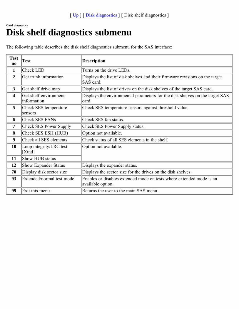
[ Up ] [ Disk diagnostics ] [ Disk shelf diagnostics ]
Card diagnostics
Disk shelf diagnostics submenuThe following table describes the disk shelf diagnostics submenu for the SAS interface:
Testno Test Description
1 Check LED Turns on the drive LEDs.2 Get trunk information Displays the list of disk shelves and their firmware revisions on the target
SAS card.3 Get shelf drive map Displays the list of drives on the disk shelves of the target SAS card.4 Get shelf environment
informationDisplays the environmental parameters for the disk shelves on the target SAScard.
5 Check SES temperaturesensors
Check SES temperature sensors against threshold value.
6 Check SES FANs Check SES fan status.7 Check SES Power Supply Check SES Power Supply status.8 Check SES ESH (HUB) Option not available.9 Check all SES elements Check status of all SES elements in the shelf.10 Loop integrity/LRC test
[Xtnd]Option not available.
11 Show HUB status12 Show Expander Status Displays the expander status.70 Display disk sector size Displays the sector size for the drives on the disk shelves.93 Extended/normal test mode Enables or disables extended mode on tests where extended mode is an
available option.99 Exit this menu Returns the user to the main SAS menu.
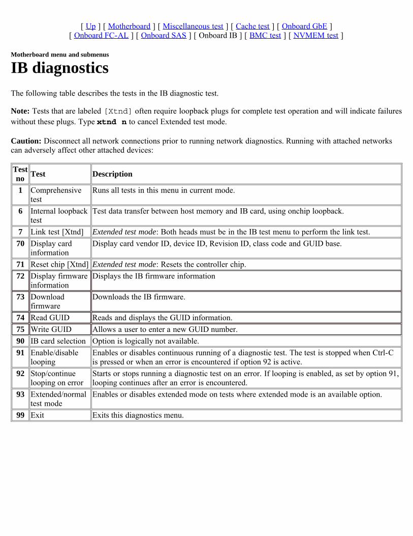
[ Up ] [ Motherboard ] [ Miscellaneous test ] [ Cache test ] [ Onboard GbE ][ Onboard FC-AL ] [ Onboard SAS ] [ Onboard IB ] [ BMC test ] [ NVMEM test ]
Motherboard menu and submenus
IB diagnosticsThe following table describes the tests in the IB diagnostic test.
Note: Tests that are labeled [Xtnd] often require loopback plugs for complete test operation and will indicate failureswithout these plugs. Type xtnd n to cancel Extended test mode.
Caution: Disconnect all network connections prior to running network diagnostics. Running with attached networkscan adversely affect other attached devices:
Testno Test Description
1 Comprehensivetest
Runs all tests in this menu in current mode.
6 Internal loopbacktest
Test data transfer between host memory and IB card, using onchip loopback.
7 Link test [Xtnd] Extended test mode: Both heads must be in the IB test menu to perform the link test.70 Display card
informationDisplay card vendor ID, device ID, Revision ID, class code and GUID base.
71 Reset chip [Xtnd] Extended test mode: Resets the controller chip.72 Display firmware
informationDisplays the IB firmware information
73 Downloadfirmware
Downloads the IB firmware.
74 Read GUID Reads and displays the GUID information.75 Write GUID Allows a user to enter a new GUID number.90 IB card selection Option is logically not available.91 Enable/disable
loopingEnables or disables continuous running of a diagnostic test. The test is stopped when Ctrl-Cis pressed or when an error is encountered if option 92 is active.
92 Stop/continuelooping on error
Starts or stops running a diagnostic test on an error. If looping is enabled, as set by option 91,looping continues after an error is encountered.
93 Extended/normaltest mode
Enables or disables extended mode on tests where extended mode is an available option.
99 Exit Exits this diagnostics menu.
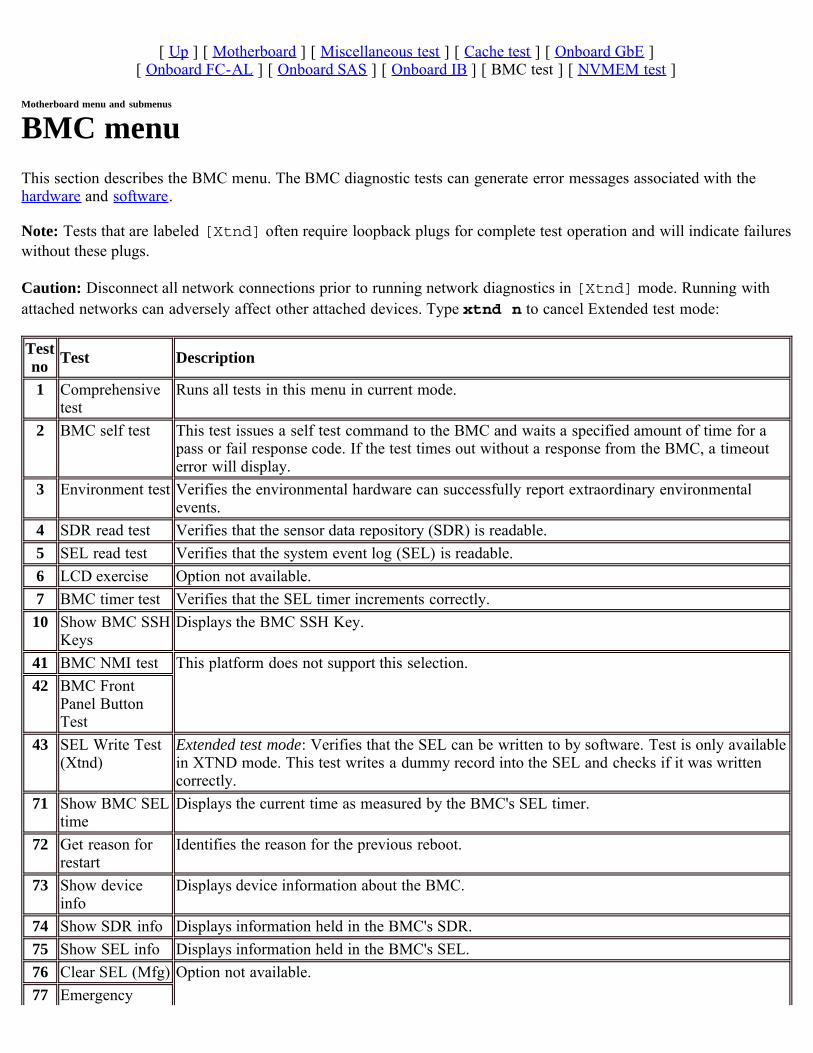
[ Up ] [ Motherboard ] [ Miscellaneous test ] [ Cache test ] [ Onboard GbE ][ Onboard FC-AL ] [ Onboard SAS ] [ Onboard IB ] [ BMC test ] [ NVMEM test ]
Motherboard menu and submenus
BMC menuThis section describes the BMC menu. The BMC diagnostic tests can generate error messages associated with thehardware and software.
Note: Tests that are labeled [Xtnd] often require loopback plugs for complete test operation and will indicate failureswithout these plugs.
Caution: Disconnect all network connections prior to running network diagnostics in [Xtnd] mode. Running withattached networks can adversely affect other attached devices. Type xtnd n to cancel Extended test mode:
Testno Test Description
1 Comprehensivetest
Runs all tests in this menu in current mode.
2 BMC self test This test issues a self test command to the BMC and waits a specified amount of time for apass or fail response code. If the test times out without a response from the BMC, a timeouterror will display.
3 Environment test Verifies the environmental hardware can successfully report extraordinary environmentalevents.
4 SDR read test Verifies that the sensor data repository (SDR) is readable.5 SEL read test Verifies that the system event log (SEL) is readable.6 LCD exercise Option not available.7 BMC timer test Verifies that the SEL timer increments correctly.10 Show BMC SSH
KeysDisplays the BMC SSH Key.
41 BMC NMI test This platform does not support this selection.42 BMC Front
Panel ButtonTest
43 SEL Write Test(Xtnd)
Extended test mode: Verifies that the SEL can be written to by software. Test is only availablein XTND mode. This test writes a dummy record into the SEL and checks if it was writtencorrectly.
71 Show BMC SELtime
Displays the current time as measured by the BMC's SEL timer.
72 Get reason forrestart
Identifies the reason for the previous reboot.
73 Show deviceinfo
Displays device information about the BMC.
74 Show SDR info Displays information held in the BMC's SDR.75 Show SEL info Displays information held in the BMC's SEL.76 Clear SEL (Mfg) Option not available.77 Emergency
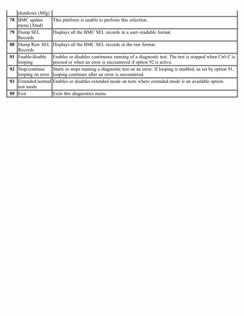
shutdown (Mfg)78 BMC update
menu (Xtnd)This platform is unable to perform this selection.
79 Dump SELRecords
Displays all the BMC SEL records in a user-readable format.
80 Dump Raw SELRecords
Displays all the BMC SEL records in the raw format.
91 Enable/disablelooping
Enables or disables continuous running of a diagnostic test. The test is stopped when Ctrl-C ispressed or when an error is encountered if option 92 is active.
92 Stop/continuelooping on error
Starts or stops running a diagnostic test on an error. If looping is enabled, as set by option 91,looping continues after an error is encountered.
93 Extended/normaltest mode
Enables or disables extended mode on tests where extended mode is an available option.
99 Exit Exits this diagnostics menu.
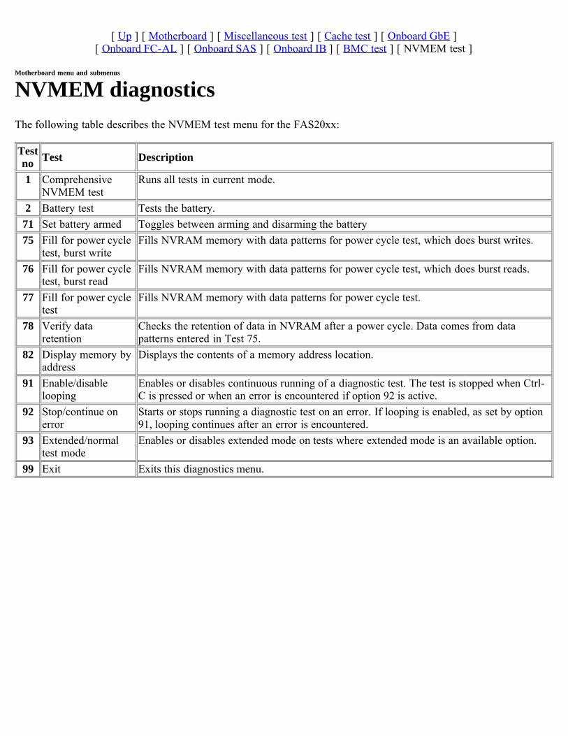
[ Up ] [ Motherboard ] [ Miscellaneous test ] [ Cache test ] [ Onboard GbE ][ Onboard FC-AL ] [ Onboard SAS ] [ Onboard IB ] [ BMC test ] [ NVMEM test ]
Motherboard menu and submenus
NVMEM diagnosticsThe following table describes the NVMEM test menu for the FAS20xx:
Testno Test Description
1 ComprehensiveNVMEM test
Runs all tests in current mode.
2 Battery test Tests the battery.71 Set battery armed Toggles between arming and disarming the battery75 Fill for power cycle
test, burst writeFills NVRAM memory with data patterns for power cycle test, which does burst writes.
76 Fill for power cycletest, burst read
Fills NVRAM memory with data patterns for power cycle test, which does burst reads.
77 Fill for power cycletest
Fills NVRAM memory with data patterns for power cycle test.
78 Verify dataretention
Checks the retention of data in NVRAM after a power cycle. Data comes from datapatterns entered in Test 75.
82 Display memory byaddress
Displays the contents of a memory address location.
91 Enable/disablelooping
Enables or disables continuous running of a diagnostic test. The test is stopped when Ctrl-C is pressed or when an error is encountered if option 92 is active.
92 Stop/continue onerror
Starts or stops running a diagnostic test on an error. If looping is enabled, as set by option91, looping continues after an error is encountered.
93 Extended/normaltest mode
Enables or disables extended mode on tests where extended mode is an available option.
99 Exit Exits this diagnostics menu.
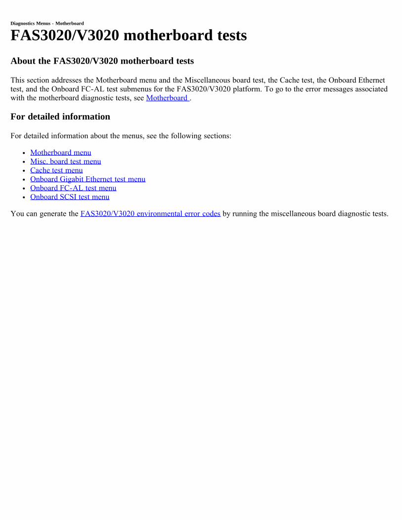
Diagnostics Menus - Motherboard
FAS3020/V3020 motherboard testsAbout the FAS3020/V3020 motherboard tests
This section addresses the Motherboard menu and the Miscellaneous board test, the Cache test, the Onboard Ethernettest, and the Onboard FC-AL test submenus for the FAS3020/V3020 platform. To go to the error messages associatedwith the motherboard diagnostic tests, see Motherboard .
For detailed information
For detailed information about the menus, see the following sections:
Motherboard menuMisc. board test menuCache test menuOnboard Gigabit Ethernet test menuOnboard FC-AL test menuOnboard SCSI test menu
You can generate the FAS3020/V3020 environmental error codes by running the miscellaneous board diagnostic tests.

[ Up ] [ Motherboard ] [ Miscellaneous test ] [ Cache test ] [ Onboard GbE ] [ Onboard FC-AL ] [ Onboard SCSI ]
Motherboard menu and submenus
Motherboard menuThis section describes the Motherboard menu:
Testno Test Description
1 Comprehensivemotherboard diag
Runs all tests in this menu in current mode.
2 Misc. board testmenu
Accesses the miscellaneous motherboard test menu.
3 Cache test menu Accesses the CPU cache tests. For more information, see the Cache test menu.4 Onboard Gigabit
Ethernet test menuAccesses the onboard Gigabit Ethernet test menu.
5 Onboard FCAL testmenu
Accesses the onboard FC-AL test menu.
6 Onboard SCSI testmenu
Accesses the onboard SCSI test menu.
71 Show PCIconfiguration
Lists the contents of all adapters in the PCI slots on the motherboard.
72 Show detailed PCIinfo
Displays detailed information about the contents and settings of the cards in the PCI slots.
73 Initialize real-timeclock
Initializes the onboard real-time clock to user-defined settings.
74 Show system info Displays information about the system.75 Serial info setup
menu [Factory only]Option not available.
76 Show Adapter cardinfo [Mfg only]
Option not available.
91 Enable/disablelooping
Enables or disables continuous running of a diagnostic test. The test is stopped when Ctrl-C is pressed or when an error is encountered if option 92 is active.
92 Stop/continuelooping on error
Starts or stops running a diagnostic test on an error. If looping is enabled, as set by option91, looping continues after an error is encountered.
93 Extended/normal testmode
Enables or disables extended mode on tests where extended mode is an available option.
99 Exit Exits this diagnostics menu.
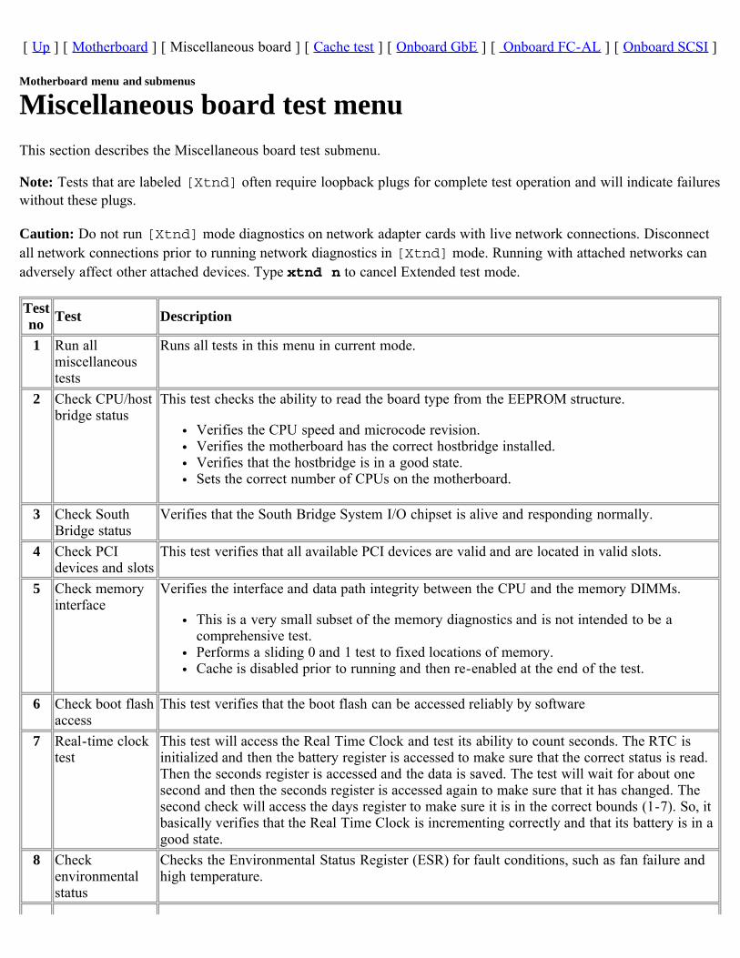
[ Up ] [ Motherboard ] [ Miscellaneous board ] [ Cache test ] [ Onboard GbE ] [ Onboard FC-AL ] [ Onboard SCSI ]
Motherboard menu and submenus
Miscellaneous board test menuThis section describes the Miscellaneous board test submenu.
Note: Tests that are labeled [Xtnd] often require loopback plugs for complete test operation and will indicate failureswithout these plugs.
Caution: Do not run [Xtnd] mode diagnostics on network adapter cards with live network connections. Disconnectall network connections prior to running network diagnostics in [Xtnd] mode. Running with attached networks canadversely affect other attached devices. Type xtnd n to cancel Extended test mode.
Testno Test Description
1 Run allmiscellaneoustests
Runs all tests in this menu in current mode.
2 Check CPU/hostbridge status
This test checks the ability to read the board type from the EEPROM structure.
Verifies the CPU speed and microcode revision.Verifies the motherboard has the correct hostbridge installed.Verifies that the hostbridge is in a good state.Sets the correct number of CPUs on the motherboard.
3 Check SouthBridge status
Verifies that the South Bridge System I/O chipset is alive and responding normally.
4 Check PCIdevices and slots
This test verifies that all available PCI devices are valid and are located in valid slots.
5 Check memoryinterface
Verifies the interface and data path integrity between the CPU and the memory DIMMs.
This is a very small subset of the memory diagnostics and is not intended to be acomprehensive test.Performs a sliding 0 and 1 test to fixed locations of memory.Cache is disabled prior to running and then re-enabled at the end of the test.
6 Check boot flashaccess
This test verifies that the boot flash can be accessed reliably by software
7 Real-time clocktest
This test will access the Real Time Clock and test its ability to count seconds. The RTC isinitialized and then the battery register is accessed to make sure that the correct status is read.Then the seconds register is accessed and the data is saved. The test will wait for about onesecond and then the seconds register is accessed again to make sure that it has changed. Thesecond check will access the days register to make sure it is in the correct bounds (1-7). So, itbasically verifies that the Real Time Clock is incrementing correctly and that its battery is in agood state.
8 Checkenvironmentalstatus
Checks the Environmental Status Register (ESR) for fault conditions, such as fan failure andhigh temperature.
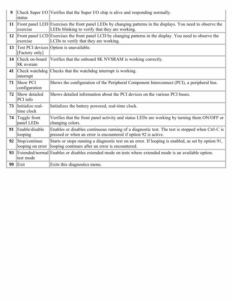
9 Check Super I/Ostatus
Verifies that the Super I/O chip is alive and responding normally.
11 Front panel LEDexercise
Exercises the front panel LEDs by changing patterns in the displays. You need to observe theLEDs blinking to verify that they are working.
12 Front panel LCDexercise
Exercises the front panel LCD by changing patterns in the display. You need to observe theLCDs to verify that they are working.
13 Test PCI devices[Factory only]
Option is unavailable.
14 Check on-board8K nvsram
Verifies that the onboard 8K NVSRAM is working correctly.
41 Check watchdoginterrupt
Checks that the watchdog interrupt is working.
71 Show PCIconfiguration
Shows the configuration of the Peripheral Component Interconnect (PCI), a peripheral bus.
72 Show detailedPCI info
Shows detailed information about the PCI devices on the various PCI buses.
73 Initialize real-time clock
Initializes the battery powered, real-time clock.
74 Toggle frontpanel LEDs
Verifies that the front panel activity and status LEDs are working by turning them ON/OFF orchanging colors.
91 Enable/disablelooping
Enables or disables continuous running of a diagnostic test. The test is stopped when Ctrl-C ispressed or when an error is encountered if option 92 is active.
92 Stop/continuelooping on error
Starts or stops running a diagnostic test on an error. If looping is enabled, as set by option 91,looping continues after an error is encountered.
93 Extended/normaltest mode
Enables or disables extended mode on tests where extended mode is an available option.
99 Exit Exits this diagnostics menu.
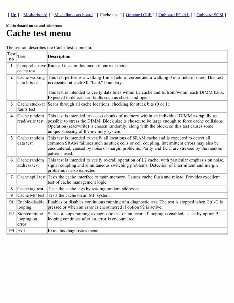
[ Up ] [ Motherboard ] [ Miscellaneous board ] [ Cache test ] [ Onboard GbE ] [ Onboard FC-AL ] [ Onboard SCSI ]
Motherboard menu and submenus
Cache test menuThe section describes the Cache test submenu.Testno Test Description
1 Comprehensivecache test
Runs all tests in this menu in current mode.
2 Cache walkingdata bits test
This test performs a walking 1 in a field of zeroes and a walking 0 in a field of ones. This testis repeated at each 8K "bank" boundary.
This test is intended to verify data lines within L2 cache and to/from/within each DIMM bank.Expected to detect hard faults such as shorts and opens.
3 Cache stuck-atfaults test
Scans through all cache locations, checking for stuck bits (0 or 1).
4 Cache randomread/write test
This test is intended to access chunks of memory within an individual DIMM as rapidly aspossible to stress the DIMM. Block size is chosen to be large enough to force cache collisions.Operation (read/write) is chosen randomly, along with the block, so this test causes someunique stressing of the memory system.
5 Cache randomdata test
This test is intended to verify all locations of SRAM cache and is expected to detect allcommon SRAM failures such as stuck cells or cell coupling. Intermittent errors may also beencountered, caused by noise or margin problems. Parity and ECC are stressed by the randompatterns used.
6 Cache randomaddress test
This test is intended to verify overall operation of L2 cache, with particular emphasis on noise,signal coupling and simultaneous switching problems. Detection of intermittent and marginproblems is also expected.
7 Cache spill test Tests the cache interface to main memory. Causes cache flush and reload. Provides excellenttest of cache management logic.
8 Cache tag test Tests the cache tags by reading random addresses.9 Cache MP test Tests the cache on an MP system.91 Enable/disable
loopingEnables or disables continuous running of a diagnostic test. The test is stopped when Ctrl-C ispressed or when an error is encountered if option 92 is active.
92 Stop/continuelooping onerror
Starts or stops running a diagnostic test on an error. If looping is enabled, as set by option 91,looping continues after an error is encountered.
99 Exit Exits this diagnostics menu.
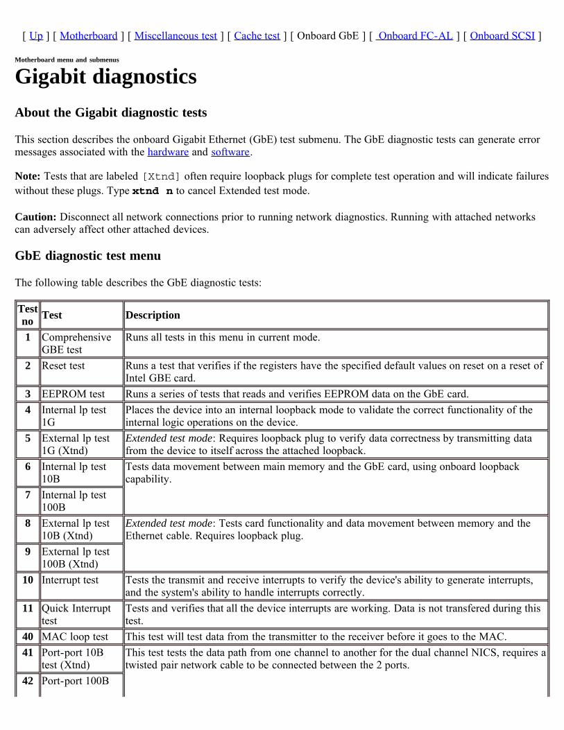
[ Up ] [ Motherboard ] [ Miscellaneous test ] [ Cache test ] [ Onboard GbE ] [ Onboard FC-AL ] [ Onboard SCSI ]
Motherboard menu and submenus
Gigabit diagnosticsAbout the Gigabit diagnostic tests
This section describes the onboard Gigabit Ethernet (GbE) test submenu. The GbE diagnostic tests can generate errormessages associated with the hardware and software.
Note: Tests that are labeled [Xtnd] often require loopback plugs for complete test operation and will indicate failureswithout these plugs. Type xtnd n to cancel Extended test mode.
Caution: Disconnect all network connections prior to running network diagnostics. Running with attached networkscan adversely affect other attached devices.
GbE diagnostic test menu
The following table describes the GbE diagnostic tests:
Testno Test Description
1 ComprehensiveGBE test
Runs all tests in this menu in current mode.
2 Reset test Runs a test that verifies if the registers have the specified default values on reset on a reset ofIntel GBE card.
3 EEPROM test Runs a series of tests that reads and verifies EEPROM data on the GbE card.4 Internal lp test
1GPlaces the device into an internal loopback mode to validate the correct functionality of theinternal logic operations on the device.
5 External lp test1G (Xtnd)
Extended test mode: Requires loopback plug to verify data correctness by transmitting datafrom the device to itself across the attached loopback.
6 Internal lp test10B
Tests data movement between main memory and the GbE card, using onboard loopbackcapability.
7 Internal lp test100B
8 External lp test10B (Xtnd)
Extended test mode: Tests card functionality and data movement between memory and theEthernet cable. Requires loopback plug.
9 External lp test100B (Xtnd)
10 Interrupt test Tests the transmit and receive interrupts to verify the device's ability to generate interrupts,and the system's ability to handle interrupts correctly.
11 Quick Interrupttest
Tests and verifies that all the device interrupts are working. Data is not transfered during thistest.
40 MAC loop test This test will test data from the transmitter to the receiver before it goes to the MAC.41 Port-port 10B
test (Xtnd)This test tests the data path from one channel to another for the dual channel NICS, requires atwisted pair network cable to be connected between the 2 ports.
42 Port-port 100B
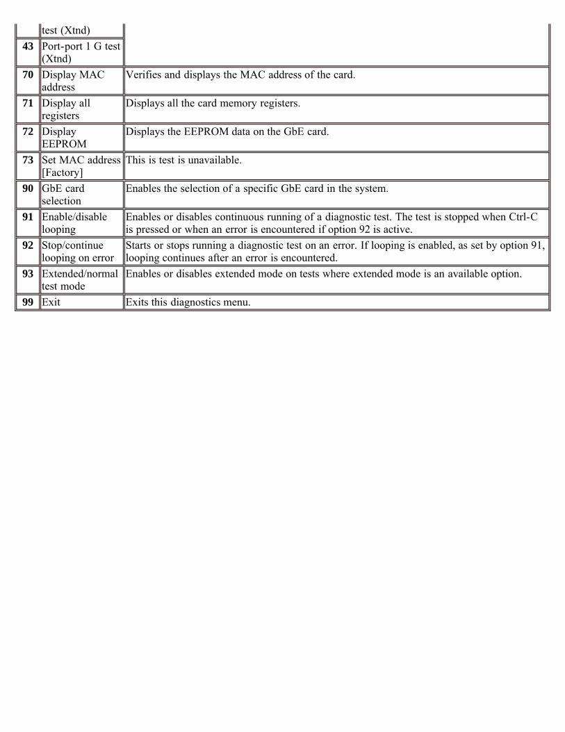
test (Xtnd)43 Port-port 1 G test
(Xtnd)70 Display MAC
addressVerifies and displays the MAC address of the card.
71 Display allregisters
Displays all the card memory registers.
72 DisplayEEPROM
Displays the EEPROM data on the GbE card.
73 Set MAC address[Factory]
This is test is unavailable.
90 GbE cardselection
Enables the selection of a specific GbE card in the system.
91 Enable/disablelooping
Enables or disables continuous running of a diagnostic test. The test is stopped when Ctrl-Cis pressed or when an error is encountered if option 92 is active.
92 Stop/continuelooping on error
Starts or stops running a diagnostic test on an error. If looping is enabled, as set by option 91,looping continues after an error is encountered.
93 Extended/normaltest mode
Enables or disables extended mode on tests where extended mode is an available option.
99 Exit Exits this diagnostics menu.
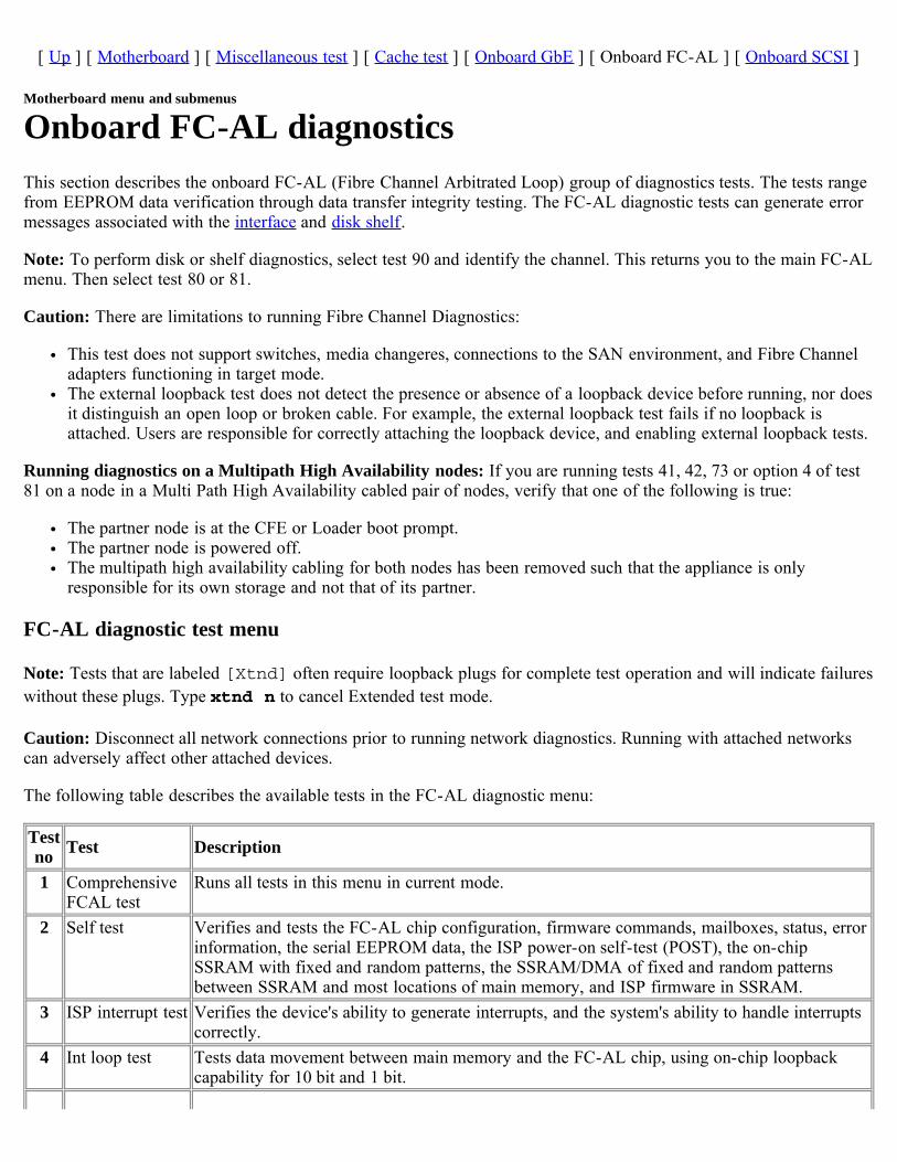
[ Up ] [ Motherboard ] [ Miscellaneous test ] [ Cache test ] [ Onboard GbE ] [ Onboard FC-AL ] [ Onboard SCSI ]
Motherboard menu and submenus
Onboard FC-AL diagnosticsThis section describes the onboard FC-AL (Fibre Channel Arbitrated Loop) group of diagnostics tests. The tests rangefrom EEPROM data verification through data transfer integrity testing. The FC-AL diagnostic tests can generate errormessages associated with the interface and disk shelf.
Note: To perform disk or shelf diagnostics, select test 90 and identify the channel. This returns you to the main FC-ALmenu. Then select test 80 or 81.
Caution: There are limitations to running Fibre Channel Diagnostics:
This test does not support switches, media changeres, connections to the SAN environment, and Fibre Channeladapters functioning in target mode.The external loopback test does not detect the presence or absence of a loopback device before running, nor doesit distinguish an open loop or broken cable. For example, the external loopback test fails if no loopback isattached. Users are responsible for correctly attaching the loopback device, and enabling external loopback tests.
Running diagnostics on a Multipath High Availability nodes: If you are running tests 41, 42, 73 or option 4 of test81 on a node in a Multi Path High Availability cabled pair of nodes, verify that one of the following is true:
The partner node is at the CFE or Loader boot prompt.The partner node is powered off.The multipath high availability cabling for both nodes has been removed such that the appliance is onlyresponsible for its own storage and not that of its partner.
FC-AL diagnostic test menu
Note: Tests that are labeled [Xtnd] often require loopback plugs for complete test operation and will indicate failureswithout these plugs. Type xtnd n to cancel Extended test mode.
Caution: Disconnect all network connections prior to running network diagnostics. Running with attached networkscan adversely affect other attached devices.
The following table describes the available tests in the FC-AL diagnostic menu:
Testno Test Description
1 ComprehensiveFCAL test
Runs all tests in this menu in current mode.
2 Self test Verifies and tests the FC-AL chip configuration, firmware commands, mailboxes, status, errorinformation, the serial EEPROM data, the ISP power-on self-test (POST), the on-chipSSRAM with fixed and random patterns, the SSRAM/DMA of fixed and random patternsbetween SSRAM and most locations of main memory, and ISP firmware in SSRAM.
3 ISP interrupt test Verifies the device's ability to generate interrupts, and the system's ability to handle interruptscorrectly.
4 Int loop test Tests data movement between main memory and the FC-AL chip, using on-chip loopbackcapability for 10 bit and 1 bit.
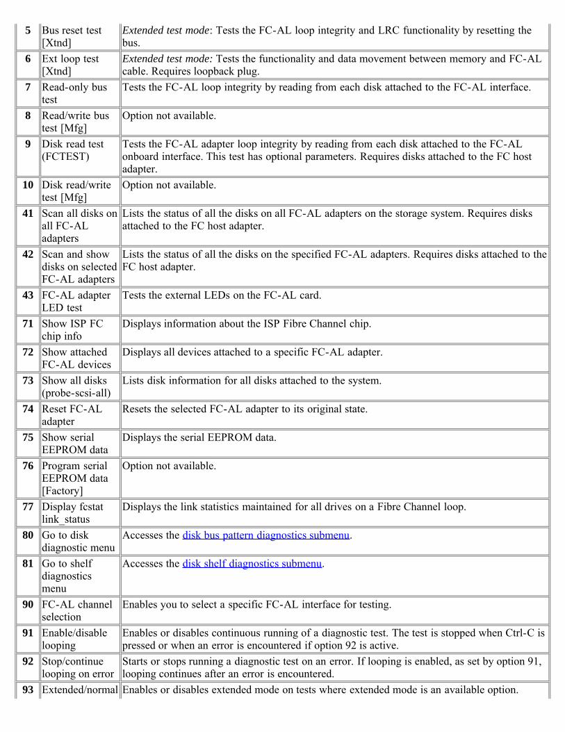
5 Bus reset test[Xtnd]
Extended test mode: Tests the FC-AL loop integrity and LRC functionality by resetting thebus.
6 Ext loop test[Xtnd]
Extended test mode: Tests the functionality and data movement between memory and FC-ALcable. Requires loopback plug.
7 Read-only bustest
Tests the FC-AL loop integrity by reading from each disk attached to the FC-AL interface.
8 Read/write bustest [Mfg]
Option not available.
9 Disk read test(FCTEST)
Tests the FC-AL adapter loop integrity by reading from each disk attached to the FC-ALonboard interface. This test has optional parameters. Requires disks attached to the FC hostadapter.
10 Disk read/writetest [Mfg]
Option not available.
41 Scan all disks onall FC-ALadapters
Lists the status of all the disks on all FC-AL adapters on the storage system. Requires disksattached to the FC host adapter.
42 Scan and showdisks on selectedFC-AL adapters
Lists the status of all the disks on the specified FC-AL adapters. Requires disks attached to theFC host adapter.
43 FC-AL adapterLED test
Tests the external LEDs on the FC-AL card.
71 Show ISP FCchip info
Displays information about the ISP Fibre Channel chip.
72 Show attachedFC-AL devices
Displays all devices attached to a specific FC-AL adapter.
73 Show all disks(probe-scsi-all)
Lists disk information for all disks attached to the system.
74 Reset FC-ALadapter
Resets the selected FC-AL adapter to its original state.
75 Show serialEEPROM data
Displays the serial EEPROM data.
76 Program serialEEPROM data[Factory]
Option not available.
77 Display fcstatlink_status
Displays the link statistics maintained for all drives on a Fibre Channel loop.
80 Go to diskdiagnostic menu
Accesses the disk bus pattern diagnostics submenu.
81 Go to shelfdiagnosticsmenu
Accesses the disk shelf diagnostics submenu.
90 FC-AL channelselection
Enables you to select a specific FC-AL interface for testing.
91 Enable/disablelooping
Enables or disables continuous running of a diagnostic test. The test is stopped when Ctrl-C ispressed or when an error is encountered if option 92 is active.
92 Stop/continuelooping on error
Starts or stops running a diagnostic test on an error. If looping is enabled, as set by option 91,looping continues after an error is encountered.
93 Extended/normal Enables or disables extended mode on tests where extended mode is an available option.

test mode99 Exit Exits this diagnostics menu.

[ Up ] [ Disk diagnostics ] [ Disk shelf diagnostics ]
Card diagnostics
Disk diagnostics submenuThe following table describes the FC-AL disk diagnostics submenu:
Testno Test Description
1 Perform drive selfdiagnostic test
The drive seeks a reserved non user-accessible cylinder and writes, reads, andverifies data for each data surface.
2 Low frequency pattern[Mfg]
Option not available.
3 Low transition densitypattern [Mfg]
4 Half-rate square pattern[Mfg]
5 Quarter-rate squarepattern [Mfg]
6 Contiguous '3' pattern[Mfg]
7 Composite pattern [Mfg]40 Read drive defect list Displays primary and grown defect list. This test has optional parameters. Requires
disks attached to the FC host adapter.99 Exit this menu Returns the user to the main FC-AL menu.

[ Up ] [ Disk diagnostics ] [ Disk shelf diagnostics ]
Disk shelf diagnostics submenuThe following table describes the disk shelf diagnostics submenu for the FC-AL interface.
Note: Tests that are labeled [Xtnd] often require loopback plugs for complete test operation and indicate failureswithout these plugs.
Caution: Do not run [Xtnd] mode diagnostics on network adapters with live network connections. Disconnect allnetwork connections prior to running network diagnostics in [Xtnd] mode. Running with attached networks canadversely affect other attached devices. Enter xtnd n to cancel Extended test mode:
Testno Test Description
1 Turn shelf LED on Turns on the drive LEDs.2 Turn shelf LED off Turns off the drive LEDs.3 Get trunk information Option not available.4 Get shelf drive map Displays the list of drives on target FC-AL interface.5 Get shelf environment
informationDisplays the environmental parameters on the target FC-AL interface.
6 Check SES temperature sensors Checks SES temperature sensors against threshold value.7 Check SES Fans Checks SES fan status.8 Check SES power supply Checks SES power supply status.9 Check SES ESH (HUB) Option not available.
10 Check all SES elements Check status of all SES elements in the shelf.11 Loop integrity/LRC test [Xtnd] Extended test mode: Tests the FC-AL loop integrity and LRC functionality.12 Show HUB status Option not available.70 Display sector size for FC-AL
devicesDisplays the sector size for the drives on the disk shelves.
93 Extended/normal test mode Enables or disables extended mode on tests where extended mode is anavailable option.
99 Exit this menu Returns the user to the main FC-AL menu.
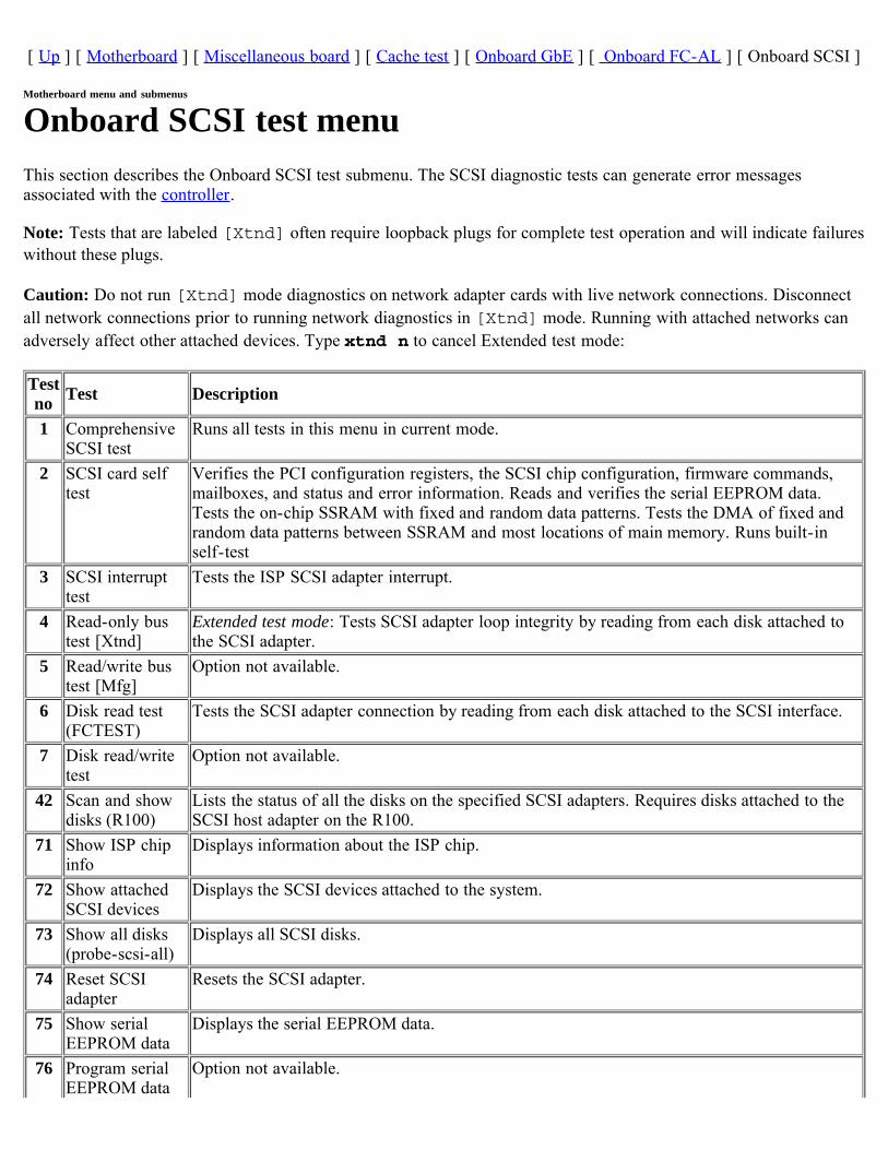
[ Up ] [ Motherboard ] [ Miscellaneous board ] [ Cache test ] [ Onboard GbE ] [ Onboard FC-AL ] [ Onboard SCSI ]
Motherboard menu and submenus
Onboard SCSI test menuThis section describes the Onboard SCSI test submenu. The SCSI diagnostic tests can generate error messagesassociated with the controller.
Note: Tests that are labeled [Xtnd] often require loopback plugs for complete test operation and will indicate failureswithout these plugs.
Caution: Do not run [Xtnd] mode diagnostics on network adapter cards with live network connections. Disconnectall network connections prior to running network diagnostics in [Xtnd] mode. Running with attached networks canadversely affect other attached devices. Type xtnd n to cancel Extended test mode:
Testno Test Description
1 ComprehensiveSCSI test
Runs all tests in this menu in current mode.
2 SCSI card selftest
Verifies the PCI configuration registers, the SCSI chip configuration, firmware commands,mailboxes, and status and error information. Reads and verifies the serial EEPROM data.Tests the on-chip SSRAM with fixed and random data patterns. Tests the DMA of fixed andrandom data patterns between SSRAM and most locations of main memory. Runs built-inself-test
3 SCSI interrupttest
Tests the ISP SCSI adapter interrupt.
4 Read-only bustest [Xtnd]
Extended test mode: Tests SCSI adapter loop integrity by reading from each disk attached tothe SCSI adapter.
5 Read/write bustest [Mfg]
Option not available.
6 Disk read test(FCTEST)
Tests the SCSI adapter connection by reading from each disk attached to the SCSI interface.
7 Disk read/writetest
Option not available.
42 Scan and showdisks (R100)
Lists the status of all the disks on the specified SCSI adapters. Requires disks attached to theSCSI host adapter on the R100.
71 Show ISP chipinfo
Displays information about the ISP chip.
72 Show attachedSCSI devices
Displays the SCSI devices attached to the system.
73 Show all disks(probe-scsi-all)
Displays all SCSI disks.
74 Reset SCSIadapter
Resets the SCSI adapter.
75 Show serialEEPROM data
Displays the serial EEPROM data.
76 Program serialEEPROM data
Option not available.
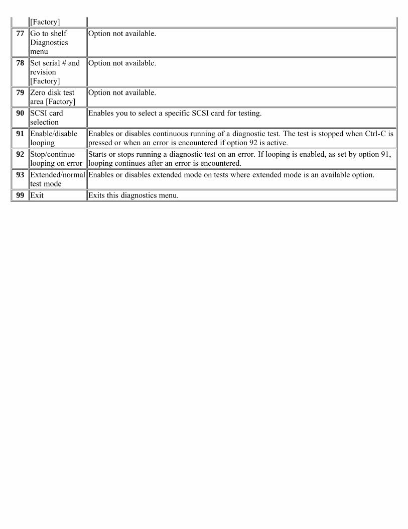
[Factory]77 Go to shelf
Diagnosticsmenu
Option not available.
78 Set serial # andrevision[Factory]
Option not available.
79 Zero disk testarea [Factory]
Option not available.
90 SCSI cardselection
Enables you to select a specific SCSI card for testing.
91 Enable/disablelooping
Enables or disables continuous running of a diagnostic test. The test is stopped when Ctrl-C ispressed or when an error is encountered if option 92 is active.
92 Stop/continuelooping on error
Starts or stops running a diagnostic test on an error. If looping is enabled, as set by option 91,looping continues after an error is encountered.
93 Extended/normaltest mode
Enables or disables extended mode on tests where extended mode is an available option.
99 Exit Exits this diagnostics menu.
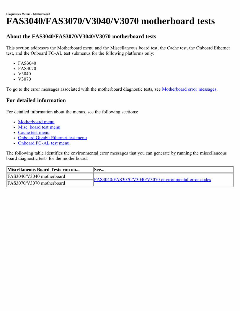
Diagnostics Menus - Motherboard
FAS3040/FAS3070/V3040/V3070 motherboard testsAbout the FAS3040/FAS3070/V3040/V3070 motherboard tests
This section addresses the Motherboard menu and the Miscellaneous board test, the Cache test, the Onboard Ethernettest, and the Onboard FC-AL test submenus for the following platforms only:
FAS3040FAS3070V3040V3070
To go to the error messages associated with the motherboard diagnostic tests, see Motherboard error messages.
For detailed information
For detailed information about the menus, see the following sections:
Motherboard menuMisc. board test menuCache test menuOnboard Gigabit Ethernet test menuOnboard FC-AL test menu
The following table identifies the environmental error messages that you can generate by running the miscellaneousboard diagnostic tests for the motherboard:
Miscellaneous Board Tests run on... See...FAS3040/V3040 motherboard
FAS3040/FAS3070/V3040/V3070 environmental error codesFAS3070/V3070 motherboard
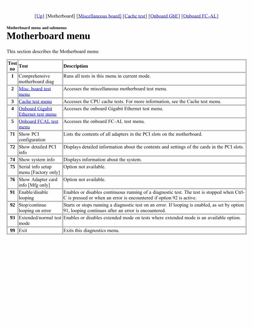
[Up] [Motherboard] [Miscellaneous board] [Cache test] [Onboard GbE] [Onboard FC-AL]
Motherboard menu and submenus
Motherboard menuThis section describes the Motherboard menu:
Testno Test Description
1 Comprehensivemotherboard diag
Runs all tests in this menu in current mode.
2 Misc. board testmenu
Accesses the miscellaneous motherboard test menu.
3 Cache test menu Accesses the CPU cache tests. For more information, see the Cache test menu.4 Onboard Gigabit
Ethernet test menuAccesses the onboard Gigabit Ethernet test menu.
5 Onboard FCAL testmenu
Accesses the onboard FC-AL test menu.
71 Show PCIconfiguration
Lists the contents of all adapters in the PCI slots on the motherboard.
72 Show detailed PCIinfo
Displays detailed information about the contents and settings of the cards in the PCI slots.
74 Show system info Displays information about the system.75 Serial info setup
menu [Factory only]Option not available.
76 Show Adapter cardinfo [Mfg only]
Option not available.
91 Enable/disablelooping
Enables or disables continuous running of a diagnostic test. The test is stopped when Ctrl-C is pressed or when an error is encountered if option 92 is active.
92 Stop/continuelooping on error
Starts or stops running a diagnostic test on an error. If looping is enabled, as set by option91, looping continues after an error is encountered.
93 Extended/normal testmode
Enables or disables extended mode on tests where extended mode is an available option.
99 Exit Exits this diagnostics menu.
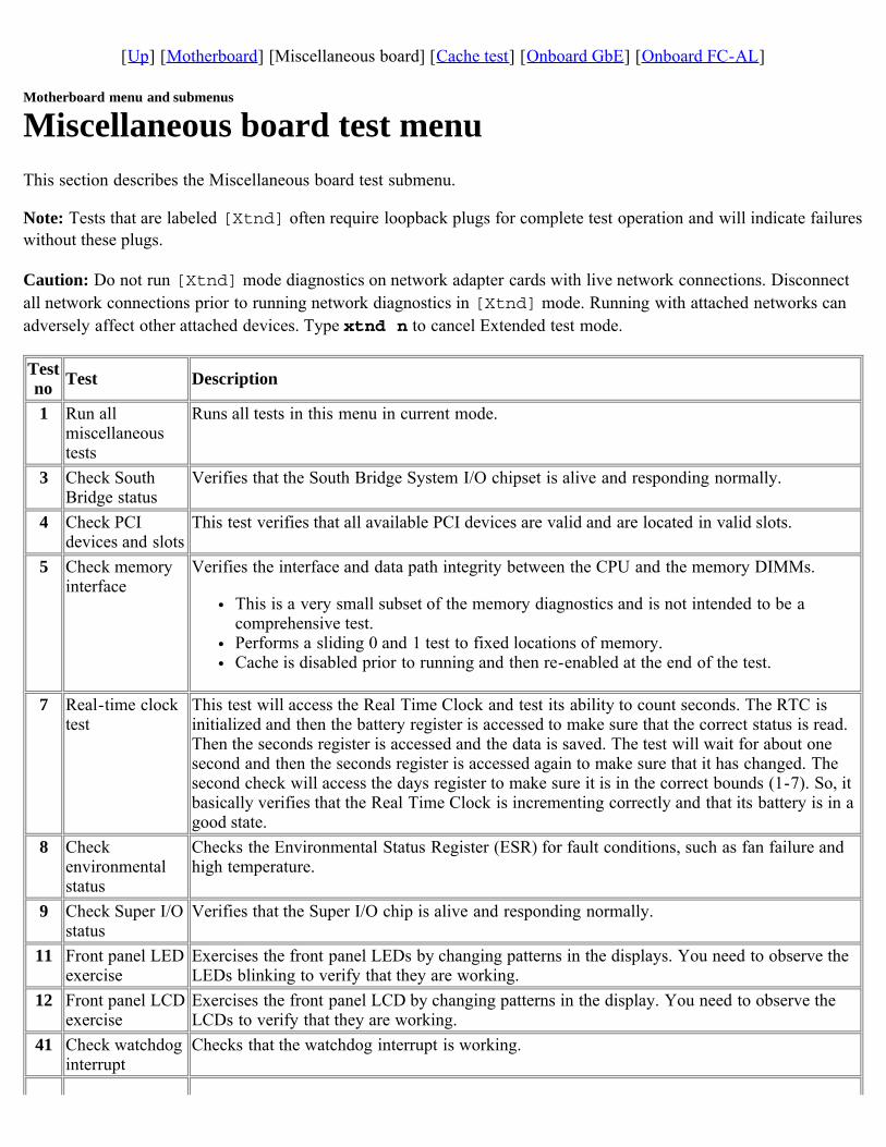
[Up] [Motherboard] [Miscellaneous board] [Cache test] [Onboard GbE] [Onboard FC-AL]
Motherboard menu and submenus
Miscellaneous board test menuThis section describes the Miscellaneous board test submenu.
Note: Tests that are labeled [Xtnd] often require loopback plugs for complete test operation and will indicate failureswithout these plugs.
Caution: Do not run [Xtnd] mode diagnostics on network adapter cards with live network connections. Disconnectall network connections prior to running network diagnostics in [Xtnd] mode. Running with attached networks canadversely affect other attached devices. Type xtnd n to cancel Extended test mode.
Testno Test Description
1 Run allmiscellaneoustests
Runs all tests in this menu in current mode.
3 Check SouthBridge status
Verifies that the South Bridge System I/O chipset is alive and responding normally.
4 Check PCIdevices and slots
This test verifies that all available PCI devices are valid and are located in valid slots.
5 Check memoryinterface
Verifies the interface and data path integrity between the CPU and the memory DIMMs.
This is a very small subset of the memory diagnostics and is not intended to be acomprehensive test.Performs a sliding 0 and 1 test to fixed locations of memory.Cache is disabled prior to running and then re-enabled at the end of the test.
7 Real-time clocktest
This test will access the Real Time Clock and test its ability to count seconds. The RTC isinitialized and then the battery register is accessed to make sure that the correct status is read.Then the seconds register is accessed and the data is saved. The test will wait for about onesecond and then the seconds register is accessed again to make sure that it has changed. Thesecond check will access the days register to make sure it is in the correct bounds (1-7). So, itbasically verifies that the Real Time Clock is incrementing correctly and that its battery is in agood state.
8 Checkenvironmentalstatus
Checks the Environmental Status Register (ESR) for fault conditions, such as fan failure andhigh temperature.
9 Check Super I/Ostatus
Verifies that the Super I/O chip is alive and responding normally.
11 Front panel LEDexercise
Exercises the front panel LEDs by changing patterns in the displays. You need to observe theLEDs blinking to verify that they are working.
12 Front panel LCDexercise
Exercises the front panel LCD by changing patterns in the display. You need to observe theLCDs to verify that they are working.
41 Check watchdoginterrupt
Checks that the watchdog interrupt is working.
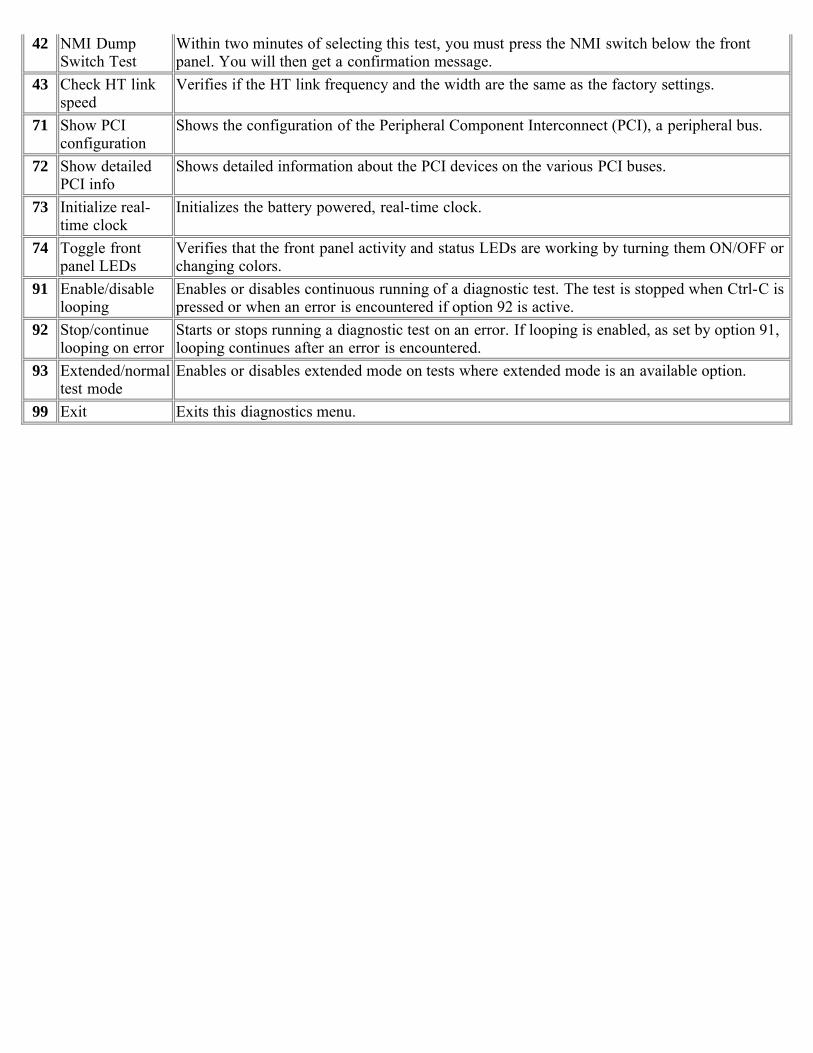
42 NMI DumpSwitch Test
Within two minutes of selecting this test, you must press the NMI switch below the frontpanel. You will then get a confirmation message.
43 Check HT linkspeed
Verifies if the HT link frequency and the width are the same as the factory settings.
71 Show PCIconfiguration
Shows the configuration of the Peripheral Component Interconnect (PCI), a peripheral bus.
72 Show detailedPCI info
Shows detailed information about the PCI devices on the various PCI buses.
73 Initialize real-time clock
Initializes the battery powered, real-time clock.
74 Toggle frontpanel LEDs
Verifies that the front panel activity and status LEDs are working by turning them ON/OFF orchanging colors.
91 Enable/disablelooping
Enables or disables continuous running of a diagnostic test. The test is stopped when Ctrl-C ispressed or when an error is encountered if option 92 is active.
92 Stop/continuelooping on error
Starts or stops running a diagnostic test on an error. If looping is enabled, as set by option 91,looping continues after an error is encountered.
93 Extended/normaltest mode
Enables or disables extended mode on tests where extended mode is an available option.
99 Exit Exits this diagnostics menu.
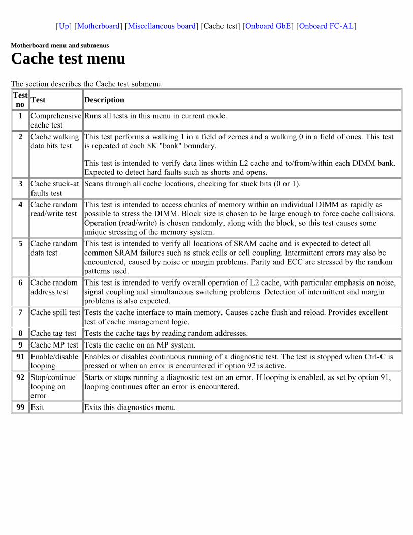
[Up] [Motherboard] [Miscellaneous board] [Cache test] [Onboard GbE] [Onboard FC-AL]
Motherboard menu and submenus
Cache test menuThe section describes the Cache test submenu.Testno Test Description
1 Comprehensivecache test
Runs all tests in this menu in current mode.
2 Cache walkingdata bits test
This test performs a walking 1 in a field of zeroes and a walking 0 in a field of ones. This testis repeated at each 8K "bank" boundary.
This test is intended to verify data lines within L2 cache and to/from/within each DIMM bank.Expected to detect hard faults such as shorts and opens.
3 Cache stuck-atfaults test
Scans through all cache locations, checking for stuck bits (0 or 1).
4 Cache randomread/write test
This test is intended to access chunks of memory within an individual DIMM as rapidly aspossible to stress the DIMM. Block size is chosen to be large enough to force cache collisions.Operation (read/write) is chosen randomly, along with the block, so this test causes someunique stressing of the memory system.
5 Cache randomdata test
This test is intended to verify all locations of SRAM cache and is expected to detect allcommon SRAM failures such as stuck cells or cell coupling. Intermittent errors may also beencountered, caused by noise or margin problems. Parity and ECC are stressed by the randompatterns used.
6 Cache randomaddress test
This test is intended to verify overall operation of L2 cache, with particular emphasis on noise,signal coupling and simultaneous switching problems. Detection of intermittent and marginproblems is also expected.
7 Cache spill test Tests the cache interface to main memory. Causes cache flush and reload. Provides excellenttest of cache management logic.
8 Cache tag test Tests the cache tags by reading random addresses.9 Cache MP test Tests the cache on an MP system.91 Enable/disable
loopingEnables or disables continuous running of a diagnostic test. The test is stopped when Ctrl-C ispressed or when an error is encountered if option 92 is active.
92 Stop/continuelooping onerror
Starts or stops running a diagnostic test on an error. If looping is enabled, as set by option 91,looping continues after an error is encountered.
99 Exit Exits this diagnostics menu.
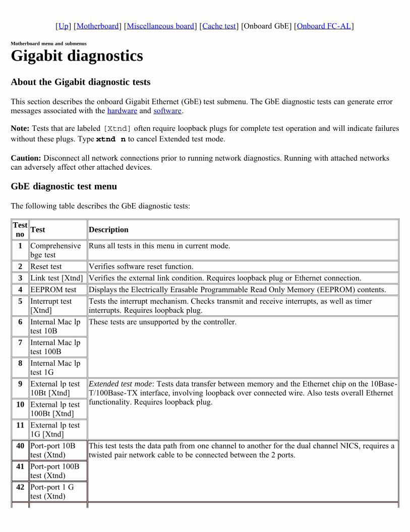
[Up] [Motherboard] [Miscellaneous board] [Cache test] [Onboard GbE] [Onboard FC-AL]
Motherboard menu and submenus
Gigabit diagnosticsAbout the Gigabit diagnostic tests
This section describes the onboard Gigabit Ethernet (GbE) test submenu. The GbE diagnostic tests can generate errormessages associated with the hardware and software.
Note: Tests that are labeled [Xtnd] often require loopback plugs for complete test operation and will indicate failureswithout these plugs. Type xtnd n to cancel Extended test mode.
Caution: Disconnect all network connections prior to running network diagnostics. Running with attached networkscan adversely affect other attached devices.
GbE diagnostic test menu
The following table describes the GbE diagnostic tests:
Testno Test Description
1 Comprehensivebge test
Runs all tests in this menu in current mode.
2 Reset test Verifies software reset function.3 Link test [Xtnd] Verifies the external link condition. Requires loopback plug or Ethernet connection.4 EEPROM test Displays the Electrically Erasable Programmable Read Only Memory (EEPROM) contents.5 Interrupt test
[Xtnd]Tests the interrupt mechanism. Checks transmit and receive interrupts, as well as timerinterrupts. Requires loopback plug.
6 Internal Mac lptest 10B
These tests are unsupported by the controller.
7 Internal Mac lptest 100B
8 Internal Mac lptest 1G
9 External lp test10Bt [Xtnd]
Extended test mode: Tests data transfer between memory and the Ethernet chip on the 10Base-T/100Base-TX interface, involving loopback over connected wire. Also tests overall Ethernetfunctionality. Requires loopback plug.10 External lp test
100Bt [Xtnd]11 External lp test
1G [Xtnd]40 Port-port 10B
test (Xtnd)This test tests the data path from one channel to another for the dual channel NICS, requires atwisted pair network cable to be connected between the 2 ports.
41 Port-port 100Btest (Xtnd)
42 Port-port 1 Gtest (Xtnd)
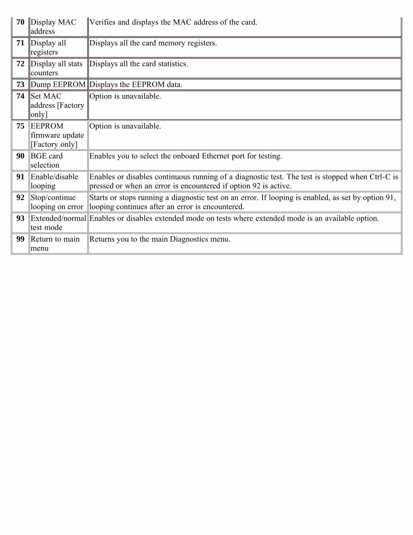
70 Display MACaddress
Verifies and displays the MAC address of the card.
71 Display allregisters
Displays all the card memory registers.
72 Display all statscounters
Displays all the card statistics.
73 Dump EEPROM Displays the EEPROM data.74 Set MAC
address [Factoryonly]
Option is unavailable.
75 EEPROMfirmware update[Factory only]
Option is unavailable.
90 BGE cardselection
Enables you to select the onboard Ethernet port for testing.
91 Enable/disablelooping
Enables or disables continuous running of a diagnostic test. The test is stopped when Ctrl-C ispressed or when an error is encountered if option 92 is active.
92 Stop/continuelooping on error
Starts or stops running a diagnostic test on an error. If looping is enabled, as set by option 91,looping continues after an error is encountered.
93 Extended/normaltest mode
Enables or disables extended mode on tests where extended mode is an available option.
99 Return to mainmenu
Returns you to the main Diagnostics menu.
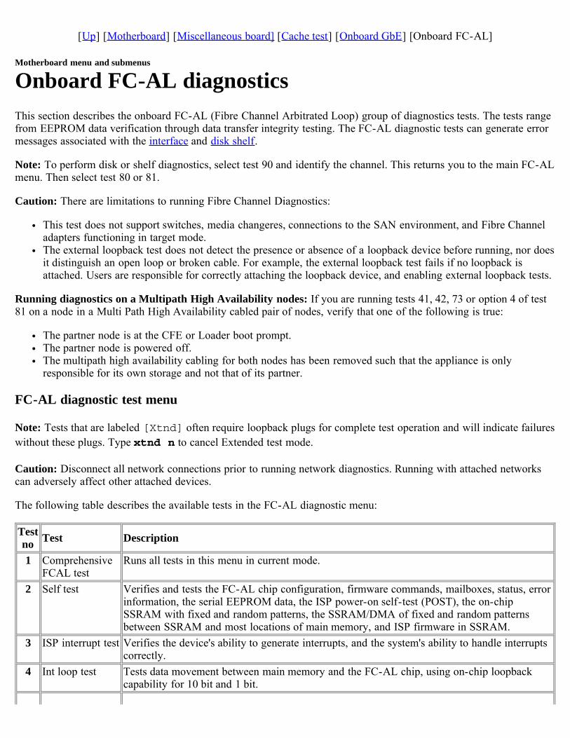
[Up] [Motherboard] [Miscellaneous board] [Cache test] [Onboard GbE] [Onboard FC-AL]
Motherboard menu and submenus
Onboard FC-AL diagnosticsThis section describes the onboard FC-AL (Fibre Channel Arbitrated Loop) group of diagnostics tests. The tests rangefrom EEPROM data verification through data transfer integrity testing. The FC-AL diagnostic tests can generate errormessages associated with the interface and disk shelf.
Note: To perform disk or shelf diagnostics, select test 90 and identify the channel. This returns you to the main FC-ALmenu. Then select test 80 or 81.
Caution: There are limitations to running Fibre Channel Diagnostics:
This test does not support switches, media changeres, connections to the SAN environment, and Fibre Channeladapters functioning in target mode.The external loopback test does not detect the presence or absence of a loopback device before running, nor doesit distinguish an open loop or broken cable. For example, the external loopback test fails if no loopback isattached. Users are responsible for correctly attaching the loopback device, and enabling external loopback tests.
Running diagnostics on a Multipath High Availability nodes: If you are running tests 41, 42, 73 or option 4 of test81 on a node in a Multi Path High Availability cabled pair of nodes, verify that one of the following is true:
The partner node is at the CFE or Loader boot prompt.The partner node is powered off.The multipath high availability cabling for both nodes has been removed such that the appliance is onlyresponsible for its own storage and not that of its partner.
FC-AL diagnostic test menu
Note: Tests that are labeled [Xtnd] often require loopback plugs for complete test operation and will indicate failureswithout these plugs. Type xtnd n to cancel Extended test mode.
Caution: Disconnect all network connections prior to running network diagnostics. Running with attached networkscan adversely affect other attached devices.
The following table describes the available tests in the FC-AL diagnostic menu:
Testno Test Description
1 ComprehensiveFCAL test
Runs all tests in this menu in current mode.
2 Self test Verifies and tests the FC-AL chip configuration, firmware commands, mailboxes, status, errorinformation, the serial EEPROM data, the ISP power-on self-test (POST), the on-chipSSRAM with fixed and random patterns, the SSRAM/DMA of fixed and random patternsbetween SSRAM and most locations of main memory, and ISP firmware in SSRAM.
3 ISP interrupt test Verifies the device's ability to generate interrupts, and the system's ability to handle interruptscorrectly.
4 Int loop test Tests data movement between main memory and the FC-AL chip, using on-chip loopbackcapability for 10 bit and 1 bit.
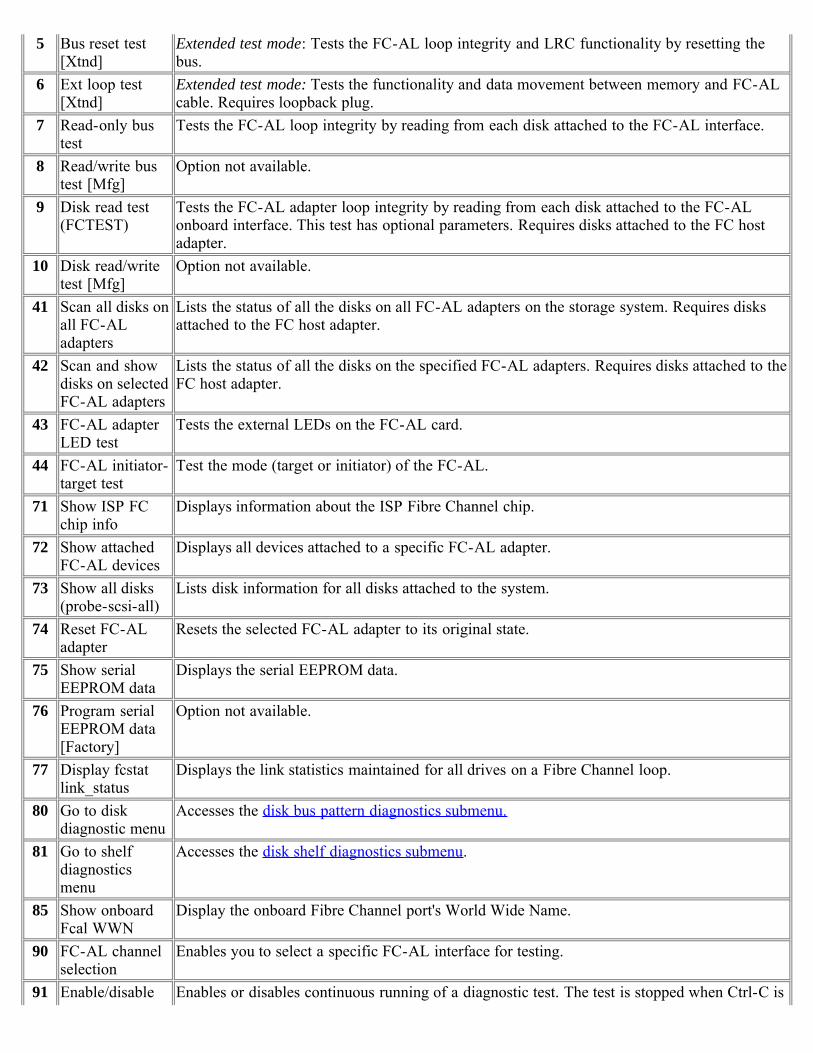
5 Bus reset test[Xtnd]
Extended test mode: Tests the FC-AL loop integrity and LRC functionality by resetting thebus.
6 Ext loop test[Xtnd]
Extended test mode: Tests the functionality and data movement between memory and FC-ALcable. Requires loopback plug.
7 Read-only bustest
Tests the FC-AL loop integrity by reading from each disk attached to the FC-AL interface.
8 Read/write bustest [Mfg]
Option not available.
9 Disk read test(FCTEST)
Tests the FC-AL adapter loop integrity by reading from each disk attached to the FC-ALonboard interface. This test has optional parameters. Requires disks attached to the FC hostadapter.
10 Disk read/writetest [Mfg]
Option not available.
41 Scan all disks onall FC-ALadapters
Lists the status of all the disks on all FC-AL adapters on the storage system. Requires disksattached to the FC host adapter.
42 Scan and showdisks on selectedFC-AL adapters
Lists the status of all the disks on the specified FC-AL adapters. Requires disks attached to theFC host adapter.
43 FC-AL adapterLED test
Tests the external LEDs on the FC-AL card.
44 FC-AL initiator-target test
Test the mode (target or initiator) of the FC-AL.
71 Show ISP FCchip info
Displays information about the ISP Fibre Channel chip.
72 Show attachedFC-AL devices
Displays all devices attached to a specific FC-AL adapter.
73 Show all disks(probe-scsi-all)
Lists disk information for all disks attached to the system.
74 Reset FC-ALadapter
Resets the selected FC-AL adapter to its original state.
75 Show serialEEPROM data
Displays the serial EEPROM data.
76 Program serialEEPROM data[Factory]
Option not available.
77 Display fcstatlink_status
Displays the link statistics maintained for all drives on a Fibre Channel loop.
80 Go to diskdiagnostic menu
Accesses the disk bus pattern diagnostics submenu.
81 Go to shelfdiagnosticsmenu
Accesses the disk shelf diagnostics submenu.
85 Show onboardFcal WWN
Display the onboard Fibre Channel port's World Wide Name.
90 FC-AL channelselection
Enables you to select a specific FC-AL interface for testing.
91 Enable/disable Enables or disables continuous running of a diagnostic test. The test is stopped when Ctrl-C is

looping pressed or when an error is encountered if option 92 is active.92 Stop/continue
looping on errorStarts or stops running a diagnostic test on an error. If looping is enabled, as set by option 91,looping continues after an error is encountered.
93 Extended/normaltest mode
Enables or disables extended mode on tests where extended mode is an available option.
99 Exit Exits this diagnostics menu.

[ Up ] [ Disk diagnostics ] [ Disk shelf diagnostics ]
Card diagnostics
Disk diagnostics submenuThe following table describes the FC-AL disk diagnostics submenu:
Testno Test Description
1 Perform drive selfdiagnostic test
The drive seeks a reserved non user-accessible cylinder and writes, reads, andverifies data for each data surface.
2 Low frequency pattern[Mfg]
Option not available.
3 Low transition densitypattern [Mfg]
4 Half-rate square pattern[Mfg]
5 Quarter-rate squarepattern [Mfg]
6 Contiguous '3' pattern[Mfg]
7 Composite pattern [Mfg]40 Read drive defect list Displays primary and grown defect list. This test has optional parameters. Requires
disks attached to the FC host adapter.99 Exit this menu Returns the user to the main FC-AL menu.

[ Up ] [ Disk diagnostics ] [ Disk shelf diagnostics ]
Disk shelf diagnostics submenuThe following table describes the disk shelf diagnostics submenu for the FC-AL interface.
Note: Tests that are labeled [Xtnd] often require loopback plugs for complete test operation and indicate failureswithout these plugs.
Caution: Do not run [Xtnd] mode diagnostics on network adapters with live network connections. Disconnect allnetwork connections prior to running network diagnostics in [Xtnd] mode. Running with attached networks canadversely affect other attached devices. Enter xtnd n to cancel Extended test mode:
Testno Test Description
1 Turn shelf LED on Turns on the drive LEDs.2 Turn shelf LED off Turns off the drive LEDs.3 Get trunk information Option not available.4 Get shelf drive map Displays the list of drives on target FC-AL interface.5 Get shelf environment
informationDisplays the environmental parameters on the target FC-AL interface.
6 Check SES temperature sensors Checks SES temperature sensors against threshold value.7 Check SES Fans Checks SES fan status.8 Check SES power supply Checks SES power supply status.9 Check SES ESH (HUB) Option not available.
10 Check all SES elements Check status of all SES elements in the shelf.11 Loop integrity/LRC test [Xtnd] Extended test mode: Tests the FC-AL loop integrity and LRC functionality.12 Show HUB status Option not available.70 Display sector size for FC-AL
devicesDisplays the sector size for the drives on the disk shelves.
93 Extended/normal test mode Enables or disables extended mode on tests where extended mode is anavailable option.
99 Exit this menu Returns the user to the main FC-AL menu.
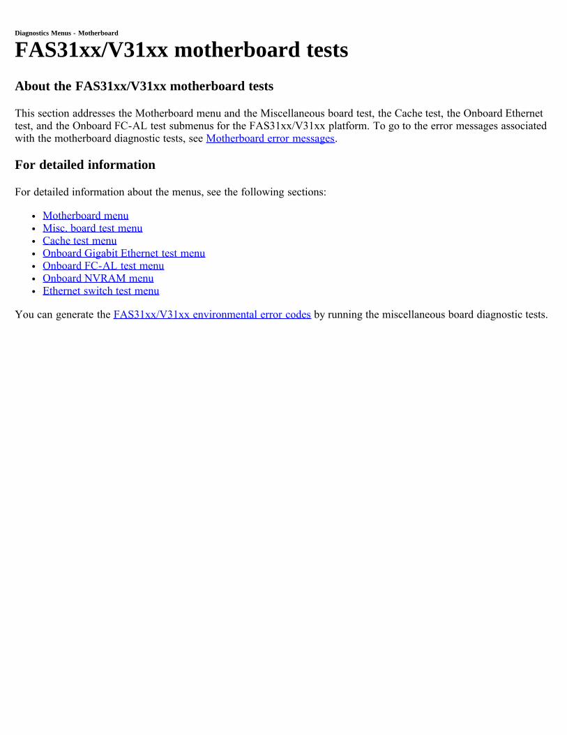
Diagnostics Menus - Motherboard
FAS31xx/V31xx motherboard testsAbout the FAS31xx/V31xx motherboard tests
This section addresses the Motherboard menu and the Miscellaneous board test, the Cache test, the Onboard Ethernettest, and the Onboard FC-AL test submenus for the FAS31xx/V31xx platform. To go to the error messages associatedwith the motherboard diagnostic tests, see Motherboard error messages.
For detailed information
For detailed information about the menus, see the following sections:
Motherboard menuMisc. board test menuCache test menuOnboard Gigabit Ethernet test menuOnboard FC-AL test menuOnboard NVRAM menuEthernet switch test menu
You can generate the FAS31xx/V31xx environmental error codes by running the miscellaneous board diagnostic tests.
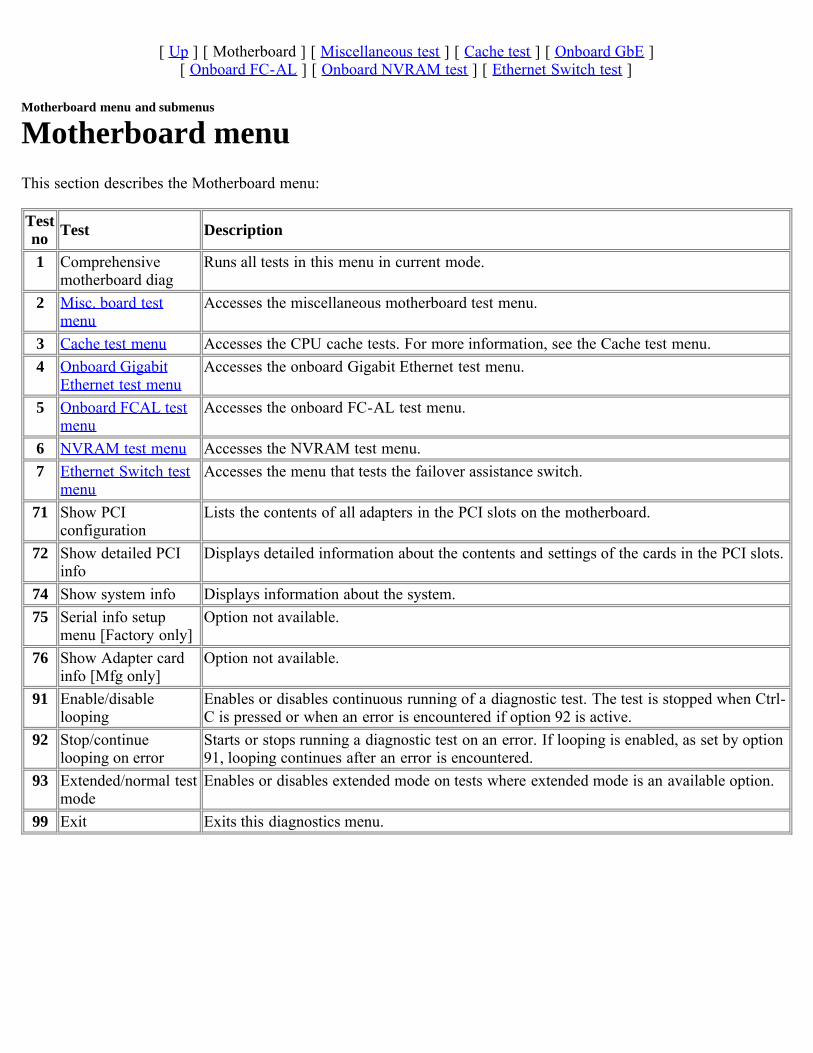
[ Up ] [ Motherboard ] [ Miscellaneous test ] [ Cache test ] [ Onboard GbE ][ Onboard FC-AL ] [ Onboard NVRAM test ] [ Ethernet Switch test ]
Motherboard menu and submenus
Motherboard menuThis section describes the Motherboard menu:
Testno Test Description
1 Comprehensivemotherboard diag
Runs all tests in this menu in current mode.
2 Misc. board testmenu
Accesses the miscellaneous motherboard test menu.
3 Cache test menu Accesses the CPU cache tests. For more information, see the Cache test menu.4 Onboard Gigabit
Ethernet test menuAccesses the onboard Gigabit Ethernet test menu.
5 Onboard FCAL testmenu
Accesses the onboard FC-AL test menu.
6 NVRAM test menu Accesses the NVRAM test menu.7 Ethernet Switch test
menuAccesses the menu that tests the failover assistance switch.
71 Show PCIconfiguration
Lists the contents of all adapters in the PCI slots on the motherboard.
72 Show detailed PCIinfo
Displays detailed information about the contents and settings of the cards in the PCI slots.
74 Show system info Displays information about the system.75 Serial info setup
menu [Factory only]Option not available.
76 Show Adapter cardinfo [Mfg only]
Option not available.
91 Enable/disablelooping
Enables or disables continuous running of a diagnostic test. The test is stopped when Ctrl-C is pressed or when an error is encountered if option 92 is active.
92 Stop/continuelooping on error
Starts or stops running a diagnostic test on an error. If looping is enabled, as set by option91, looping continues after an error is encountered.
93 Extended/normal testmode
Enables or disables extended mode on tests where extended mode is an available option.
99 Exit Exits this diagnostics menu.
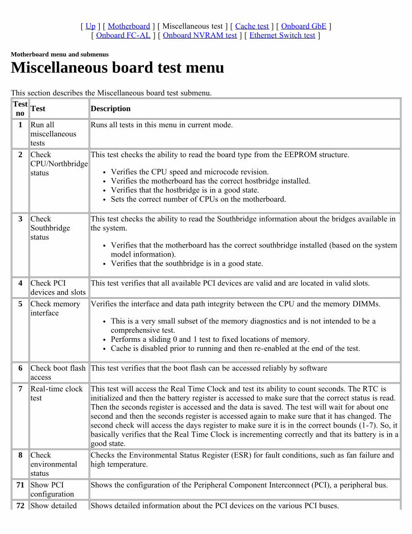
[ Up ] [ Motherboard ] [ Miscellaneous test ] [ Cache test ] [ Onboard GbE ][ Onboard FC-AL ] [ Onboard NVRAM test ] [ Ethernet Switch test ]
Motherboard menu and submenus
Miscellaneous board test menuThis section describes the Miscellaneous board test submenu. Testno Test Description
1 Run allmiscellaneoustests
Runs all tests in this menu in current mode.
2 CheckCPU/Northbridgestatus
This test checks the ability to read the board type from the EEPROM structure.
Verifies the CPU speed and microcode revision.Verifies the motherboard has the correct hostbridge installed.Verifies that the hostbridge is in a good state.Sets the correct number of CPUs on the motherboard.
3 CheckSouthbridgestatus
This test checks the ability to read the Southbridge information about the bridges available inthe system.
Verifies that the motherboard has the correct southbridge installed (based on the systemmodel information).Verifies that the southbridge is in a good state.
4 Check PCIdevices and slots
This test verifies that all available PCI devices are valid and are located in valid slots.
5 Check memoryinterface
Verifies the interface and data path integrity between the CPU and the memory DIMMs.
This is a very small subset of the memory diagnostics and is not intended to be acomprehensive test.Performs a sliding 0 and 1 test to fixed locations of memory.Cache is disabled prior to running and then re-enabled at the end of the test.
6 Check boot flashaccess
This test verifies that the boot flash can be accessed reliably by software
7 Real-time clocktest
This test will access the Real Time Clock and test its ability to count seconds. The RTC isinitialized and then the battery register is accessed to make sure that the correct status is read.Then the seconds register is accessed and the data is saved. The test will wait for about onesecond and then the seconds register is accessed again to make sure that it has changed. Thesecond check will access the days register to make sure it is in the correct bounds (1-7). So, itbasically verifies that the Real Time Clock is incrementing correctly and that its battery is in agood state.
8 Checkenvironmentalstatus
Checks the Environmental Status Register (ESR) for fault conditions, such as fan failure andhigh temperature.
71 Show PCIconfiguration
Shows the configuration of the Peripheral Component Interconnect (PCI), a peripheral bus.
72 Show detailed Shows detailed information about the PCI devices on the various PCI buses.

PCI info73 Initialize real-
time clockInitializes the battery powered, real-time clock.
91 Enable/disablelooping
Enables or disables continuous running of a diagnostic test. The test is stopped when Ctrl-C ispressed or when an error is encountered if option 92 is active.
92 Stop/continuelooping on error
Starts or stops running a diagnostic test on an error. If looping is enabled, as set by option 91,looping continues after an error is encountered.
93 Extended/normaltest mode
Enables or disables extended mode on tests where extended mode is an available option.
99 Exit Exits this diagnostics menu.
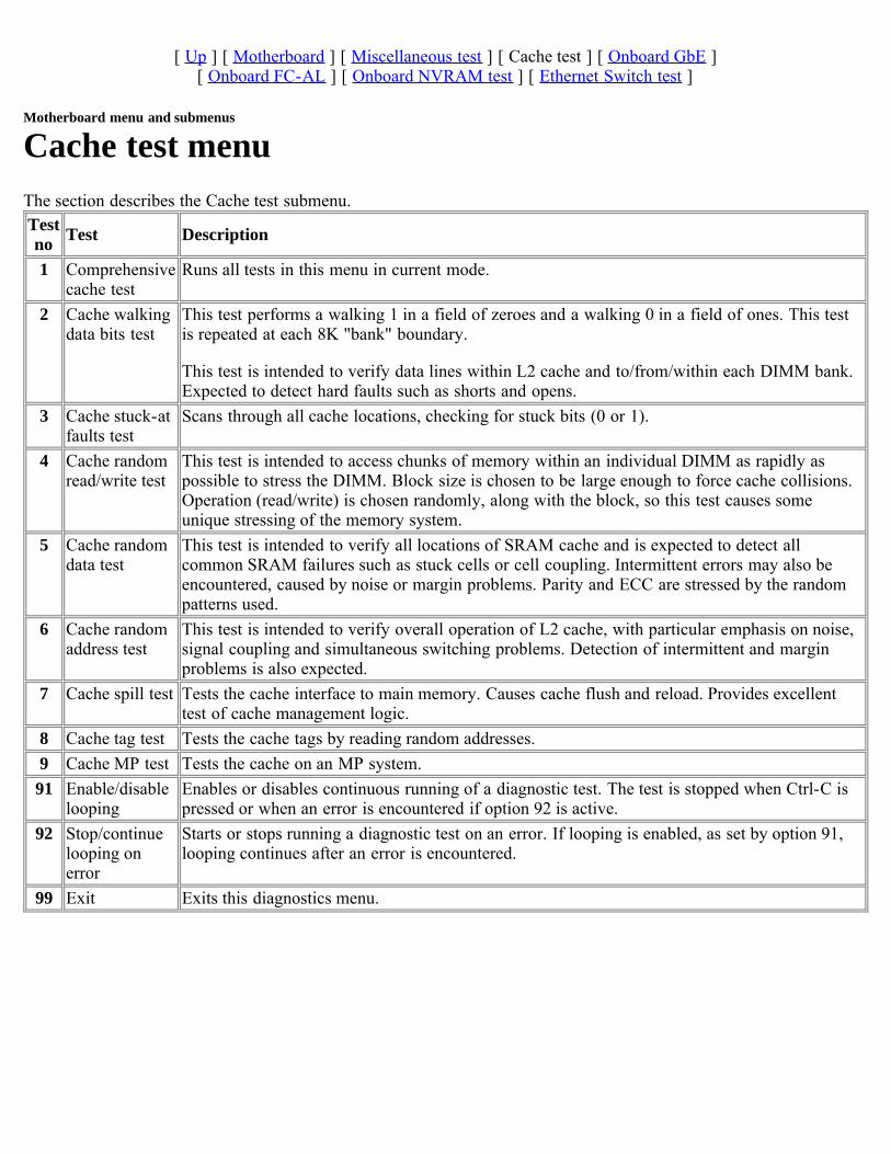
[ Up ] [ Motherboard ] [ Miscellaneous test ] [ Cache test ] [ Onboard GbE ][ Onboard FC-AL ] [ Onboard NVRAM test ] [ Ethernet Switch test ]
Motherboard menu and submenus
Cache test menuThe section describes the Cache test submenu.Testno Test Description
1 Comprehensivecache test
Runs all tests in this menu in current mode.
2 Cache walkingdata bits test
This test performs a walking 1 in a field of zeroes and a walking 0 in a field of ones. This testis repeated at each 8K "bank" boundary.
This test is intended to verify data lines within L2 cache and to/from/within each DIMM bank.Expected to detect hard faults such as shorts and opens.
3 Cache stuck-atfaults test
Scans through all cache locations, checking for stuck bits (0 or 1).
4 Cache randomread/write test
This test is intended to access chunks of memory within an individual DIMM as rapidly aspossible to stress the DIMM. Block size is chosen to be large enough to force cache collisions.Operation (read/write) is chosen randomly, along with the block, so this test causes someunique stressing of the memory system.
5 Cache randomdata test
This test is intended to verify all locations of SRAM cache and is expected to detect allcommon SRAM failures such as stuck cells or cell coupling. Intermittent errors may also beencountered, caused by noise or margin problems. Parity and ECC are stressed by the randompatterns used.
6 Cache randomaddress test
This test is intended to verify overall operation of L2 cache, with particular emphasis on noise,signal coupling and simultaneous switching problems. Detection of intermittent and marginproblems is also expected.
7 Cache spill test Tests the cache interface to main memory. Causes cache flush and reload. Provides excellenttest of cache management logic.
8 Cache tag test Tests the cache tags by reading random addresses.9 Cache MP test Tests the cache on an MP system.91 Enable/disable
loopingEnables or disables continuous running of a diagnostic test. The test is stopped when Ctrl-C ispressed or when an error is encountered if option 92 is active.
92 Stop/continuelooping onerror
Starts or stops running a diagnostic test on an error. If looping is enabled, as set by option 91,looping continues after an error is encountered.
99 Exit Exits this diagnostics menu.
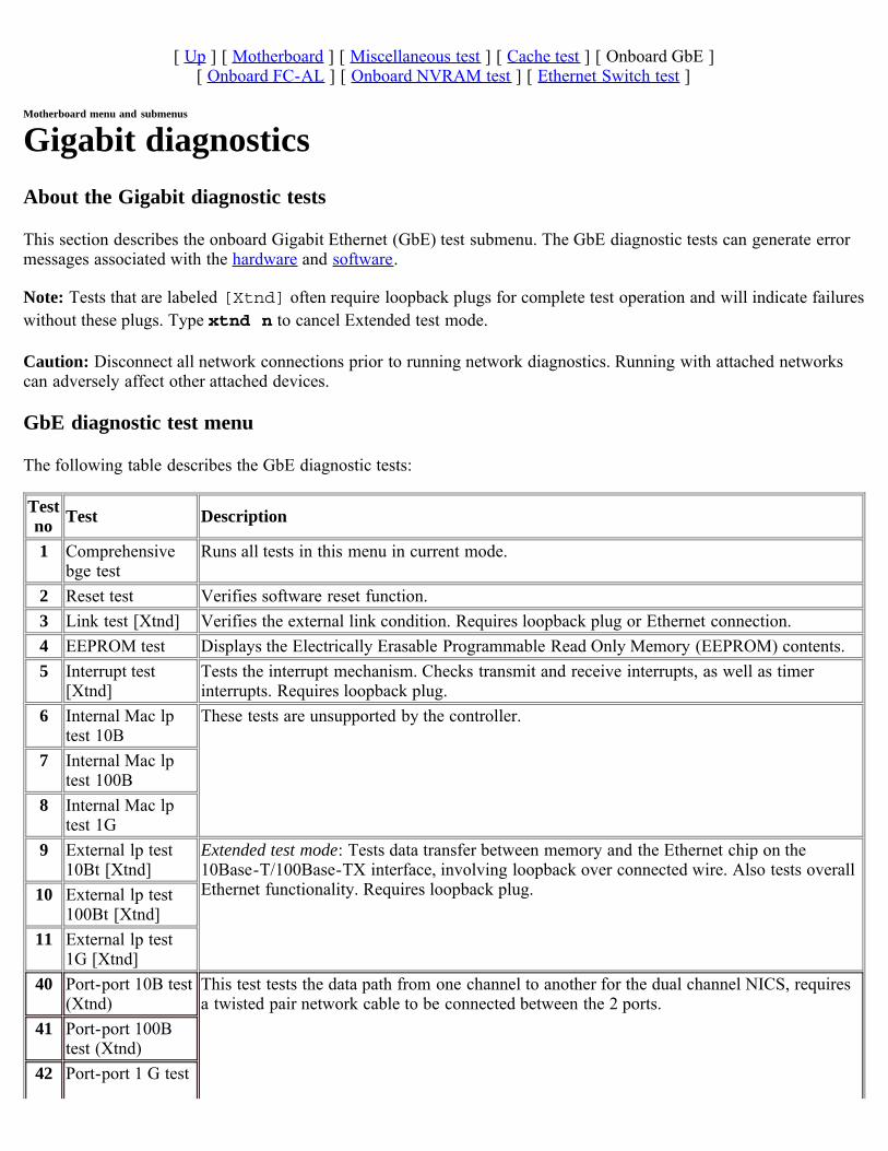
[ Up ] [ Motherboard ] [ Miscellaneous test ] [ Cache test ] [ Onboard GbE ][ Onboard FC-AL ] [ Onboard NVRAM test ] [ Ethernet Switch test ]
Motherboard menu and submenus
Gigabit diagnosticsAbout the Gigabit diagnostic tests
This section describes the onboard Gigabit Ethernet (GbE) test submenu. The GbE diagnostic tests can generate errormessages associated with the hardware and software.
Note: Tests that are labeled [Xtnd] often require loopback plugs for complete test operation and will indicate failureswithout these plugs. Type xtnd n to cancel Extended test mode.
Caution: Disconnect all network connections prior to running network diagnostics. Running with attached networkscan adversely affect other attached devices.
GbE diagnostic test menu
The following table describes the GbE diagnostic tests:
Testno Test Description
1 Comprehensivebge test
Runs all tests in this menu in current mode.
2 Reset test Verifies software reset function.3 Link test [Xtnd] Verifies the external link condition. Requires loopback plug or Ethernet connection.4 EEPROM test Displays the Electrically Erasable Programmable Read Only Memory (EEPROM) contents.5 Interrupt test
[Xtnd]Tests the interrupt mechanism. Checks transmit and receive interrupts, as well as timerinterrupts. Requires loopback plug.
6 Internal Mac lptest 10B
These tests are unsupported by the controller.
7 Internal Mac lptest 100B
8 Internal Mac lptest 1G
9 External lp test10Bt [Xtnd]
Extended test mode: Tests data transfer between memory and the Ethernet chip on the10Base-T/100Base-TX interface, involving loopback over connected wire. Also tests overallEthernet functionality. Requires loopback plug.10 External lp test
100Bt [Xtnd]11 External lp test
1G [Xtnd]40 Port-port 10B test
(Xtnd)This test tests the data path from one channel to another for the dual channel NICS, requiresa twisted pair network cable to be connected between the 2 ports.
41 Port-port 100Btest (Xtnd)
42 Port-port 1 G test
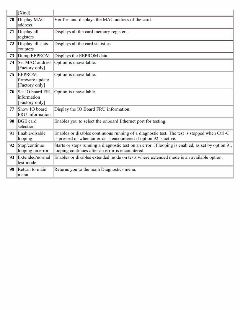
(Xtnd)70 Display MAC
addressVerifies and displays the MAC address of the card.
71 Display allregisters
Displays all the card memory registers.
72 Display all statscounters
Displays all the card statistics.
73 Dump EEPROM Displays the EEPROM data.74 Set MAC address
[Factory only]Option is unavailable.
75 EEPROMfirmware update[Factory only]
Option is unavailable.
76 Set IO board FRUinformation[Factory only]
Option is unavailable.
77 Show IO boardFRU information
Display the IO Board FRU information.
90 BGE cardselection
Enables you to select the onboard Ethernet port for testing.
91 Enable/disablelooping
Enables or disables continuous running of a diagnostic test. The test is stopped when Ctrl-Cis pressed or when an error is encountered if option 92 is active.
92 Stop/continuelooping on error
Starts or stops running a diagnostic test on an error. If looping is enabled, as set by option 91,looping continues after an error is encountered.
93 Extended/normaltest mode
Enables or disables extended mode on tests where extended mode is an available option.
99 Return to mainmenu
Returns you to the main Diagnostics menu.
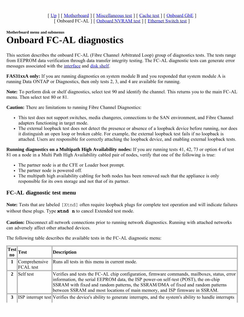
[ Up ] [ Motherboard ] [ Miscellaneous test ] [ Cache test ] [ Onboard GbE ][ Onboard FC-AL ] [ Onboard NVRAM test ] [ Ethernet Switch test ]
Motherboard menu and submenus
Onboard FC-AL diagnosticsThis section describes the onboard FC-AL (Fibre Channel Arbitrated Loop) group of diagnostics tests. The tests rangefrom EEPROM data verification through data transfer integrity testing. The FC-AL diagnostic tests can generate errormessages associated with the interface and disk shelf.
FAS31xxA only: If you are running diagnostics on system module B and you responded that system module A isrunning Data ONTAP or Diagnostics, then only tests 2, 3, and 4 are available for running.
Note: To perform disk or shelf diagnostics, select test 90 and identify the channel. This returns you to the main FC-ALmenu. Then select test 80 or 81.
Caution: There are limitations to running Fibre Channel Diagnostics:
This test does not support switches, media changeres, connections to the SAN environment, and Fibre Channeladapters functioning in target mode.The external loopback test does not detect the presence or absence of a loopback device before running, nor doesit distinguish an open loop or broken cable. For example, the external loopback test fails if no loopback isattached. Users are responsible for correctly attaching the loopback device, and enabling external loopback tests.
Running diagnostics on a Multipath High Availability nodes: If you are running tests 41, 42, 73 or option 4 of test81 on a node in a Multi Path High Availability cabled pair of nodes, verify that one of the following is true:
The partner node is at the CFE or Loader boot prompt.The partner node is powered off.The multipath high availability cabling for both nodes has been removed such that the appliance is onlyresponsible for its own storage and not that of its partner.
FC-AL diagnostic test menu
Note: Tests that are labeled [Xtnd] often require loopback plugs for complete test operation and will indicate failureswithout these plugs. Type xtnd n to cancel Extended test mode.
Caution: Disconnect all network connections prior to running network diagnostics. Running with attached networkscan adversely affect other attached devices.
The following table describes the available tests in the FC-AL diagnostic menu:
Testno Test Description
1 ComprehensiveFCAL test
Runs all tests in this menu in current mode.
2 Self test Verifies and tests the FC-AL chip configuration, firmware commands, mailboxes, status, errorinformation, the serial EEPROM data, the ISP power-on self-test (POST), the on-chipSSRAM with fixed and random patterns, the SSRAM/DMA of fixed and random patternsbetween SSRAM and most locations of main memory, and ISP firmware in SSRAM.
3 ISP interrupt test Verifies the device's ability to generate interrupts, and the system's ability to handle interrupts

correctly.4 Int loop test Tests data movement between main memory and the FC-AL chip, using on-chip loopback
capability for 10 bit and 1 bit.5 Bus reset test
[Xtnd]Extended test mode: Tests the FC-AL loop integrity and LRC functionality by resetting thebus.
6 Ext loop test[Xtnd]
Extended test mode: Tests the functionality and data movement between memory and FC-ALcable. Requires loopback plug.
7 Read-only bustest
Tests the FC-AL loop integrity by reading from each disk attached to the FC-AL interface.
8 Read/write bustest [Mfg]
Option not available.
9 Disk read test(FCTEST)
Tests the FC-AL adapter loop integrity by reading from each disk attached to the FC-ALonboard interface. This test has optional parameters. Requires disks attached to the FC hostadapter.
10 Disk read/writetest [Mfg]
Option not available.
41 Scan all disks onall FC-AL
Lists the status of all the disks on all FC-AL interfaces on the storage system. Requires disksattached to the FC host interface.
42 Scan and showdisks on selectedFC-AL
Lists the status of all the disks on the specified FC-AL interface. Requires disks attached tothe FC host interface.
43 FC-AL adapterLED test
Tests the external LEDs on the FC-AL card.
44 FC initiator-target test
The test is not supported.
71 Show ISP FCchip info
Displays information about the ISP Fibre Channel chip.
72 Show attachedFC-AL devices
Displays all devices attached to a specific FC-AL adapter.
73 Show all disks(probe-scsi-all)
Lists disk information for all disks attached to the system.
74 Reset FC-ALadapter
Resets the selected FC-AL adapter to its original state.
75 Show serialEEPROM data
Displays the serial EEPROM data.
76 Program serialEEPROM data[Factory]
Option not available.
77 Display fcstatlink_status
Displays the link statistics maintained for all drives on a Fibre Channel loop.
80 Go to diskdiagnostic menu
Accesses the disk bus pattern diagnostics submenu.
81 Go to shelfdiagnosticsmenu
Accesses the disk shelf diagnostics submenu.
90 FC-AL cardselection
Enables you to select a specific FC-AL interface for testing.
91 Enable/disable Enables or disables continuous running of a diagnostic test. The test is stopped when Ctrl-C is

looping pressed or when an error is encountered if option 92 is active.92 Stop/continue
looping on errorStarts or stops running a diagnostic test on an error. If looping is enabled, as set by option 91,looping continues after an error is encountered.
93 Extended/normaltest mode
Enables or disables extended mode on tests where extended mode is an available option.
99 Exit Exits this diagnostics menu.

[ Up ] [ Disk diagnostics ] [ Disk shelf diagnostics ]
Card diagnostics
Disk diagnostics submenuThe following table describes the FC-AL disk diagnostics submenu:
Testno Test Description
1 Perform drive selfdiagnostic test
The drive seeks a reserved non user-accessible cylinder and writes, reads, andverifies data for each data surface.
2 Low frequency pattern[Mfg]
Option not available.
3 Low transition densitypattern [Mfg]
4 Half-rate square pattern[Mfg]
5 Quarter-rate squarepattern [Mfg]
6 Marvell 8030 test pattern1 [Mfg]
7 Marvell 8030 test pattern2 [Mfg]
8 Marvell 8030 test pattern3 [Mfg]
9 Pattern 0 [Mfg]10 Contiguous '3' pattern
[Mfg]11 Composite pattern [Mfg]40 Read drive defect list Displays primary and grown defect list. This test has optional parameters. Requires
disks attached to the FC host adapter.99 Exit this menu Returns the user to the main FC-AL menu.
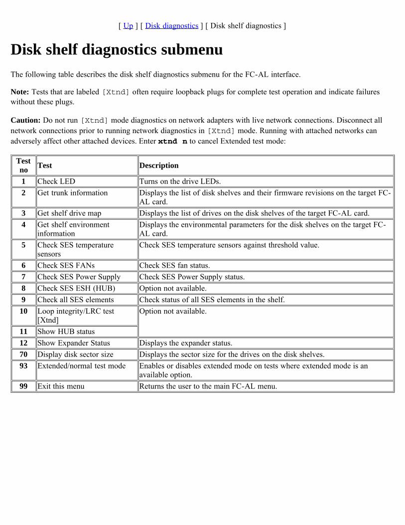
[ Up ] [ Disk diagnostics ] [ Disk shelf diagnostics ]
Disk shelf diagnostics submenuThe following table describes the disk shelf diagnostics submenu for the FC-AL interface.
Note: Tests that are labeled [Xtnd] often require loopback plugs for complete test operation and indicate failureswithout these plugs.
Caution: Do not run [Xtnd] mode diagnostics on network adapters with live network connections. Disconnect allnetwork connections prior to running network diagnostics in [Xtnd] mode. Running with attached networks canadversely affect other attached devices. Enter xtnd n to cancel Extended test mode:
Testno Test Description
1 Check LED Turns on the drive LEDs.2 Get trunk information Displays the list of disk shelves and their firmware revisions on the target FC-
AL card.3 Get shelf drive map Displays the list of drives on the disk shelves of the target FC-AL card.4 Get shelf environment
informationDisplays the environmental parameters for the disk shelves on the target FC-AL card.
5 Check SES temperaturesensors
Check SES temperature sensors against threshold value.
6 Check SES FANs Check SES fan status.7 Check SES Power Supply Check SES Power Supply status.8 Check SES ESH (HUB) Option not available.9 Check all SES elements Check status of all SES elements in the shelf.10 Loop integrity/LRC test
[Xtnd]Option not available.
11 Show HUB status12 Show Expander Status Displays the expander status.70 Display disk sector size Displays the sector size for the drives on the disk shelves.93 Extended/normal test mode Enables or disables extended mode on tests where extended mode is an
available option.99 Exit this menu Returns the user to the main FC-AL menu.
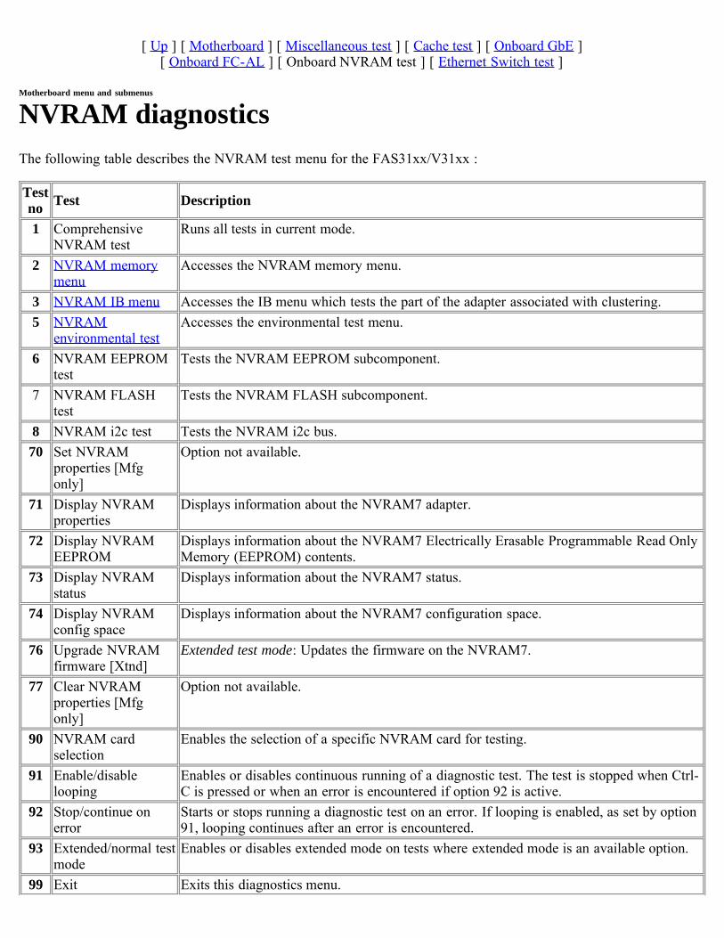
[ Up ] [ Motherboard ] [ Miscellaneous test ] [ Cache test ] [ Onboard GbE ][ Onboard FC-AL ] [ Onboard NVRAM test ] [ Ethernet Switch test ]
Motherboard menu and submenus
NVRAM diagnosticsThe following table describes the NVRAM test menu for the FAS31xx/V31xx :
Testno Test Description
1 ComprehensiveNVRAM test
Runs all tests in current mode.
2 NVRAM memorymenu
Accesses the NVRAM memory menu.
3 NVRAM IB menu Accesses the IB menu which tests the part of the adapter associated with clustering.5 NVRAM
environmental testAccesses the environmental test menu.
6 NVRAM EEPROMtest
Tests the NVRAM EEPROM subcomponent.
7 NVRAM FLASHtest
Tests the NVRAM FLASH subcomponent.
8 NVRAM i2c test Tests the NVRAM i2c bus.70 Set NVRAM
properties [Mfgonly]
Option not available.
71 Display NVRAMproperties
Displays information about the NVRAM7 adapter.
72 Display NVRAMEEPROM
Displays information about the NVRAM7 Electrically Erasable Programmable Read OnlyMemory (EEPROM) contents.
73 Display NVRAMstatus
Displays information about the NVRAM7 status.
74 Display NVRAMconfig space
Displays information about the NVRAM7 configuration space.
76 Upgrade NVRAMfirmware [Xtnd]
Extended test mode: Updates the firmware on the NVRAM7.
77 Clear NVRAMproperties [Mfgonly]
Option not available.
90 NVRAM cardselection
Enables the selection of a specific NVRAM card for testing.
91 Enable/disablelooping
Enables or disables continuous running of a diagnostic test. The test is stopped when Ctrl-C is pressed or when an error is encountered if option 92 is active.
92 Stop/continue onerror
Starts or stops running a diagnostic test on an error. If looping is enabled, as set by option91, looping continues after an error is encountered.
93 Extended/normal testmode
Enables or disables extended mode on tests where extended mode is an available option.
99 Exit Exits this diagnostics menu.

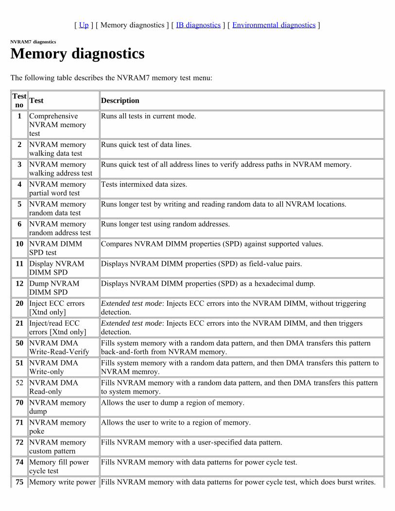
[ Up ] [ Memory diagnostics ] [ IB diagnostics ] [ Environmental diagnostics ]
NVRAM7 diagnostics
Memory diagnosticsThe following table describes the NVRAM7 memory test menu:
Testno Test Description
1 ComprehensiveNVRAM memorytest
Runs all tests in current mode.
2 NVRAM memorywalking data test
Runs quick test of data lines.
3 NVRAM memorywalking address test
Runs quick test of all address lines to verify address paths in NVRAM memory.
4 NVRAM memorypartial word test
Tests intermixed data sizes.
5 NVRAM memoryrandom data test
Runs longer test by writing and reading random data to all NVRAM locations.
6 NVRAM memoryrandom address test
Runs longer test using random addresses.
10 NVRAM DIMMSPD test
Compares NVRAM DIMM properties (SPD) against supported values.
11 Display NVRAMDIMM SPD
Displays NVRAM DIMM properties (SPD) as field-value pairs.
12 Dump NVRAMDIMM SPD
Displays NVRAM DIMM properties (SPD) as a hexadecimal dump.
20 Inject ECC errors[Xtnd only]
Extended test mode: Injects ECC errors into the NVRAM DIMM, without triggeringdetection.
21 Inject/read ECCerrors [Xtnd only]
Extended test mode: Injects ECC errors into the NVRAM DIMM, and then triggersdetection.
50 NVRAM DMAWrite-Read-Verify
Fills system memory with a random data pattern, and then DMA transfers this patternback-and-forth from NVRAM memory.
51 NVRAM DMAWrite-only
Fills system memory with a random data pattern, and then DMA transfers this pattern toNVRAM memroy.
52 NVRAM DMARead-only
Fills NVRAM memory with a random data pattern, and then DMA transfers this patternto system memory.
70 NVRAM memorydump
Allows the user to dump a region of memory.
71 NVRAM memorypoke
Allows the user to write to a region of memory.
72 NVRAM memorycustom pattern
Fills NVRAM memory with a user-specified data pattern.
74 Memory fill powercycle test
Fills NVRAM memory with data patterns for power cycle test.
75 Memory write power Fills NVRAM memory with data patterns for power cycle test, which does burst writes.
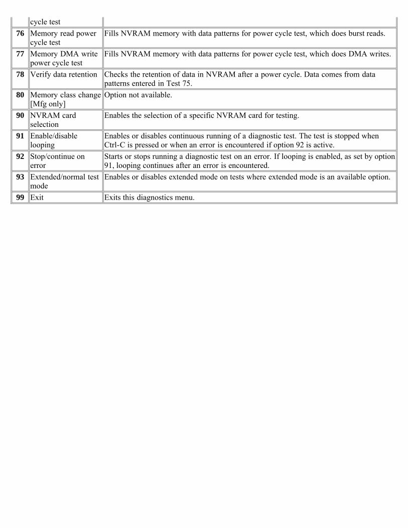
cycle test76 Memory read power
cycle testFills NVRAM memory with data patterns for power cycle test, which does burst reads.
77 Memory DMA writepower cycle test
Fills NVRAM memory with data patterns for power cycle test, which does DMA writes.
78 Verify data retention Checks the retention of data in NVRAM after a power cycle. Data comes from datapatterns entered in Test 75.
80 Memory class change[Mfg only]
Option not available.
90 NVRAM cardselection
Enables the selection of a specific NVRAM card for testing.
91 Enable/disablelooping
Enables or disables continuous running of a diagnostic test. The test is stopped whenCtrl-C is pressed or when an error is encountered if option 92 is active.
92 Stop/continue onerror
Starts or stops running a diagnostic test on an error. If looping is enabled, as set by option91, looping continues after an error is encountered.
93 Extended/normal testmode
Enables or disables extended mode on tests where extended mode is an available option.
99 Exit Exits this diagnostics menu.
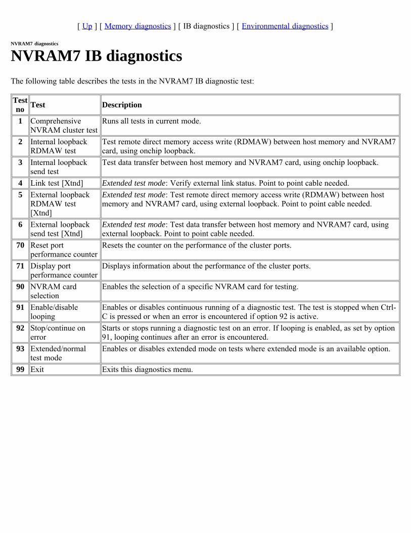
[ Up ] [ Memory diagnostics ] [ IB diagnostics ] [ Environmental diagnostics ]
NVRAM7 diagnostics
NVRAM7 IB diagnosticsThe following table describes the tests in the NVRAM7 IB diagnostic test:
Testno Test Description
1 ComprehensiveNVRAM cluster test
Runs all tests in current mode.
2 Internal loopbackRDMAW test
Test remote direct memory access write (RDMAW) between host memory and NVRAM7card, using onchip loopback.
3 Internal loopbacksend test
Test data transfer between host memory and NVRAM7 card, using onchip loopback.
4 Link test [Xtnd] Extended test mode: Verify external link status. Point to point cable needed. 5 External loopback
RDMAW test[Xtnd]
Extended test mode: Test remote direct memory access write (RDMAW) between hostmemory and NVRAM7 card, using external loopback. Point to point cable needed.
6 External loopbacksend test [Xtnd]
Extended test mode: Test data transfer between host memory and NVRAM7 card, usingexternal loopback. Point to point cable needed.
70 Reset portperformance counter
Resets the counter on the performance of the cluster ports.
71 Display portperformance counter
Displays information about the performance of the cluster ports.
90 NVRAM cardselection
Enables the selection of a specific NVRAM card for testing.
91 Enable/disablelooping
Enables or disables continuous running of a diagnostic test. The test is stopped when Ctrl-C is pressed or when an error is encountered if option 92 is active.
92 Stop/continue onerror
Starts or stops running a diagnostic test on an error. If looping is enabled, as set by option91, looping continues after an error is encountered.
93 Extended/normaltest mode
Enables or disables extended mode on tests where extended mode is an available option.
99 Exit Exits this diagnostics menu.
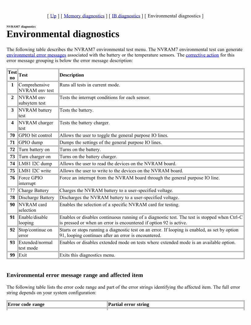
[ Up ] [ Memory diagnostics ] [ IB diagnostics ] [ Environmental diagnostics ]
NVRAM7 diagnostics
Environmental diagnosticsThe following table describes the NVRAM7 environmental test menu. The NVRAM7 environmental test can generateenvironmental error messages associated with the battery or the temperature sensors. The corrective action for thiserror message grouping is below the error message description:
Testno Test Description
1 ComprehensiveNVRAM env test
Runs all tests in current mode.
2 NVRAM envsubsytem test
Tests the interrupt conditions for each sensor.
3 NVRAM batterytest
Tests the battery.
4 NVRAM chargertest
Tests the battery charger.
70 GPIO bit control Allows the user to toggle the general purpose IO lines.71 GPIO dump Dumps the settings of the general purpose IO lines.72 Turn battery on Turns on the battery.73 Turn charger on Turns on the battery charger.74 LM81 I2C dump Allows the user to read the devices on the NVRAM board.75 LM81 I2C write Allows the user to write to the devices on the NVRAM board.76 Force GPIO
interruptForce an interrupt from the NVRAM board through the general purpose IO line.
77 Charge Battery Charges the NVRAM battery to a user-specified voltage.78 Discharge Battery Discharges the NVRAM battery to a user-specified voltage.90 NVRAM card
selectionEnables the selection of a specific NVRAM card for testing.
91 Enable/disablelooping
Enables or disables continuous running of a diagnostic test. The test is stopped when Ctrl-Cis pressed or when an error is encountered if option 92 is active.
92 Stop/continue onerror
Starts or stops running a diagnostic test on an error. If looping is enabled, as set by option91, looping continues after an error is encountered.
93 Extended/normaltest mode
Enables or disables extended mode on tests where extended mode is an available option.
99 Exit Exits this diagnostics menu.
Environmental error message range and affected item
The following table lists the error code range and part of the error strings identifying the affected item. The full errorstring depends on your system configuration:
Error code range Partial error string
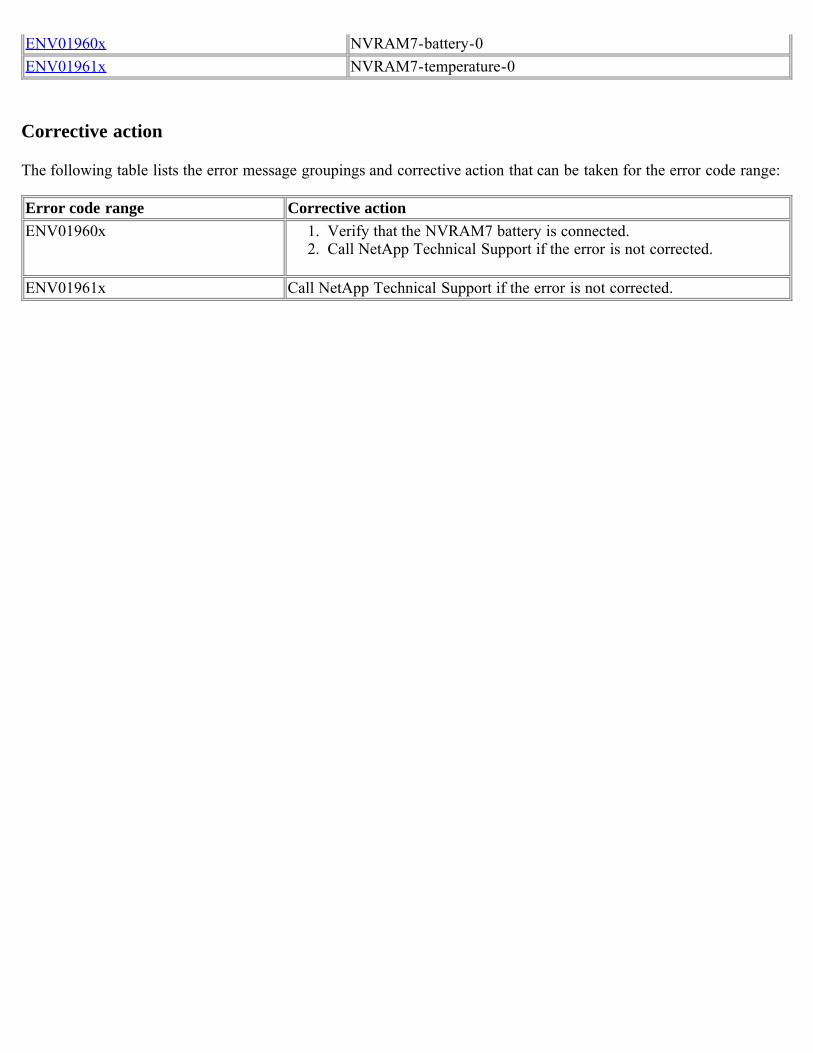
ENV01960x NVRAM7-battery-0ENV01961x NVRAM7-temperature-0
Corrective action
The following table lists the error message groupings and corrective action that can be taken for the error code range:
Error code range Corrective actionENV01960x 1. Verify that the NVRAM7 battery is connected.
2. Call NetApp Technical Support if the error is not corrected.
ENV01961x Call NetApp Technical Support if the error is not corrected.
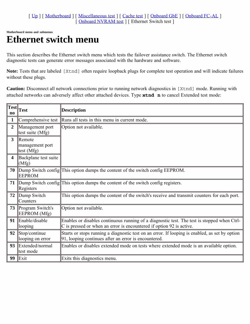
[ Up ] [ Motherboard ] [ Miscellaneous test ] [ Cache test ] [ Onboard GbE ] [ Onboard FC-AL ][ Onboard NVRAM test ] [ Ethernet Switch test ]
Motherboard menu and submenus
Ethernet switch menuThis section describes the Ethernet switch menu which tests the failover assistance switch. The Ethernet switchdiagnostic tests can generate error messages associated with the hardware and software.
Note: Tests that are labeled [Xtnd] often require loopback plugs for complete test operation and will indicate failureswithout these plugs.
Caution: Disconnect all network connections prior to running network diagnostics in [Xtnd] mode. Running withattached networks can adversely affect other attached devices. Type xtnd n to cancel Extended test mode:
Testno Test Description
1 Comprehensive test Runs all tests in this menu in current mode.2 Management port
test suite (Mfg)Option not available.
3 Remotemanagement porttest (Mfg)
4 Backplane test suite(Mfg)
70 Dump Switch configEEPROM
This option dumps the content of the switch config EEPROM.
71 Dump Switch configRegisters
This option dumps the content of the switch config registers.
72 Dump SwitchCounters
This option dumps the content of the switch's receive and transmit counters for each port.
73 Program Switch'sEEPROM (Mfg)
Option not available.
91 Enable/disablelooping
Enables or disables continuous running of a diagnostic test. The test is stopped when Ctrl-C is pressed or when an error is encountered if option 92 is active.
92 Stop/continuelooping on error
Starts or stops running a diagnostic test on an error. If looping is enabled, as set by option91, looping continues after an error is encountered.
93 Extended/normaltest mode
Enables or disables extended mode on tests where extended mode is an available option.
99 Exit Exits this diagnostics menu.
Diagnostics Menus - Motherboard
FAS60xx/V60xx/SA600 motherboard testsAbout the FAS60xx/V60xx/SA600 motherboard tests
This section addresses the Motherboard menu and the Miscellaneous board test, the Cache test, the Onboard Ethernettest, and the Onboard FC-AL test submenus for the FAS60xx/V60xx/SA600 platforms. To go to the error messagesassociated with the motherboard diagnostic tests, see Motherboard error messages.
For detailed information
For detailed information about the menus, see the following sections:
Motherboard menuMisc. board test menuCache test menuOnboard Gigabit Ethernet test menuOnboard FC-AL test menu
You can generate the FAS60xx/V60xx/SA600 environmental error codes by running the miscellaneous boarddiagnostic tests.
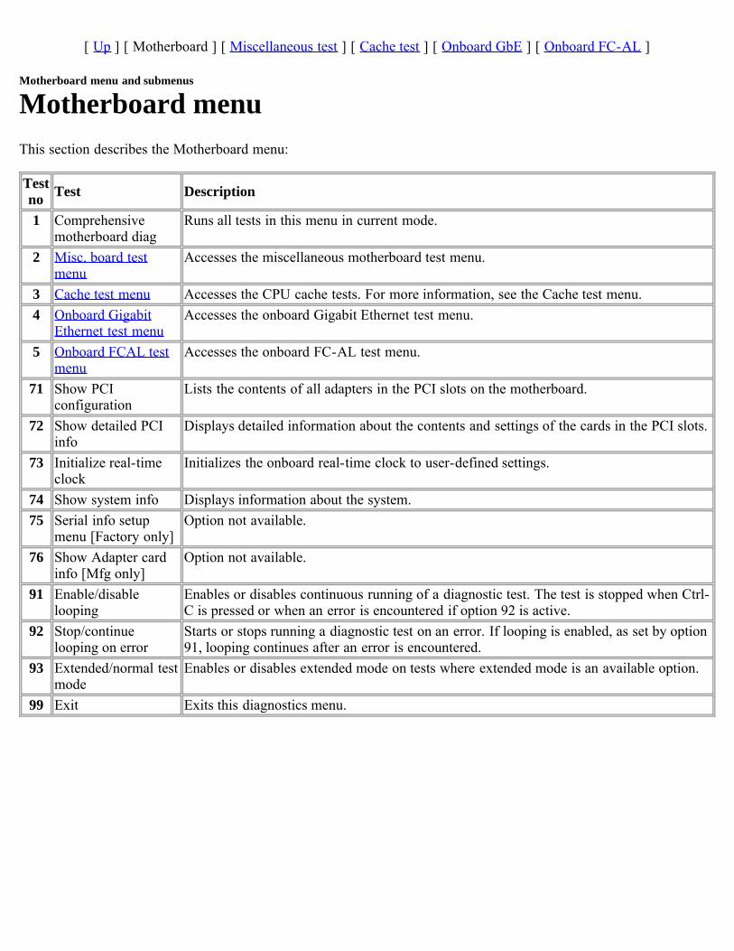
[ Up ] [ Motherboard ] [ Miscellaneous test ] [ Cache test ] [ Onboard GbE ] [ Onboard FC-AL ]
Motherboard menu and submenus
Motherboard menuThis section describes the Motherboard menu:
Testno Test Description
1 Comprehensivemotherboard diag
Runs all tests in this menu in current mode.
2 Misc. board testmenu
Accesses the miscellaneous motherboard test menu.
3 Cache test menu Accesses the CPU cache tests. For more information, see the Cache test menu.4 Onboard Gigabit
Ethernet test menuAccesses the onboard Gigabit Ethernet test menu.
5 Onboard FCAL testmenu
Accesses the onboard FC-AL test menu.
71 Show PCIconfiguration
Lists the contents of all adapters in the PCI slots on the motherboard.
72 Show detailed PCIinfo
Displays detailed information about the contents and settings of the cards in the PCI slots.
73 Initialize real-timeclock
Initializes the onboard real-time clock to user-defined settings.
74 Show system info Displays information about the system.75 Serial info setup
menu [Factory only]Option not available.
76 Show Adapter cardinfo [Mfg only]
Option not available.
91 Enable/disablelooping
Enables or disables continuous running of a diagnostic test. The test is stopped when Ctrl-C is pressed or when an error is encountered if option 92 is active.
92 Stop/continuelooping on error
Starts or stops running a diagnostic test on an error. If looping is enabled, as set by option91, looping continues after an error is encountered.
93 Extended/normal testmode
Enables or disables extended mode on tests where extended mode is an available option.
99 Exit Exits this diagnostics menu.
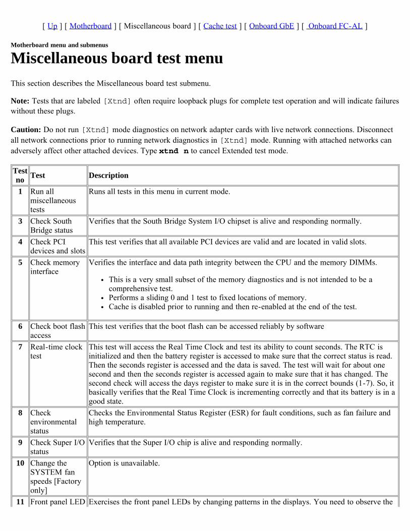
[ Up ] [ Motherboard ] [ Miscellaneous board ] [ Cache test ] [ Onboard GbE ] [ Onboard FC-AL ]
Motherboard menu and submenus
Miscellaneous board test menuThis section describes the Miscellaneous board test submenu.
Note: Tests that are labeled [Xtnd] often require loopback plugs for complete test operation and will indicate failureswithout these plugs.
Caution: Do not run [Xtnd] mode diagnostics on network adapter cards with live network connections. Disconnectall network connections prior to running network diagnostics in [Xtnd] mode. Running with attached networks canadversely affect other attached devices. Type xtnd n to cancel Extended test mode.
Testno Test Description
1 Run allmiscellaneoustests
Runs all tests in this menu in current mode.
3 Check SouthBridge status
Verifies that the South Bridge System I/O chipset is alive and responding normally.
4 Check PCIdevices and slots
This test verifies that all available PCI devices are valid and are located in valid slots.
5 Check memoryinterface
Verifies the interface and data path integrity between the CPU and the memory DIMMs.
This is a very small subset of the memory diagnostics and is not intended to be acomprehensive test.Performs a sliding 0 and 1 test to fixed locations of memory.Cache is disabled prior to running and then re-enabled at the end of the test.
6 Check boot flashaccess
This test verifies that the boot flash can be accessed reliably by software
7 Real-time clocktest
This test will access the Real Time Clock and test its ability to count seconds. The RTC isinitialized and then the battery register is accessed to make sure that the correct status is read.Then the seconds register is accessed and the data is saved. The test will wait for about onesecond and then the seconds register is accessed again to make sure that it has changed. Thesecond check will access the days register to make sure it is in the correct bounds (1-7). So, itbasically verifies that the Real Time Clock is incrementing correctly and that its battery is in agood state.
8 Checkenvironmentalstatus
Checks the Environmental Status Register (ESR) for fault conditions, such as fan failure andhigh temperature.
9 Check Super I/Ostatus
Verifies that the Super I/O chip is alive and responding normally.
10 Change theSYSTEM fanspeeds [Factoryonly]
Option is unavailable.
11 Front panel LED Exercises the front panel LEDs by changing patterns in the displays. You need to observe the
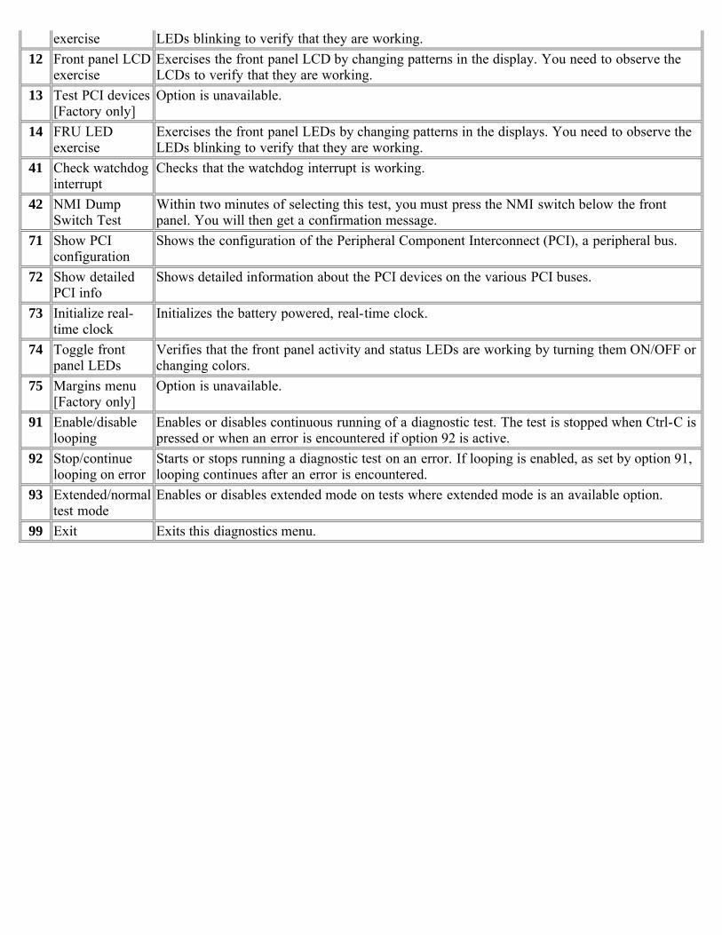
exercise LEDs blinking to verify that they are working.12 Front panel LCD
exerciseExercises the front panel LCD by changing patterns in the display. You need to observe theLCDs to verify that they are working.
13 Test PCI devices[Factory only]
Option is unavailable.
14 FRU LEDexercise
Exercises the front panel LEDs by changing patterns in the displays. You need to observe theLEDs blinking to verify that they are working.
41 Check watchdoginterrupt
Checks that the watchdog interrupt is working.
42 NMI DumpSwitch Test
Within two minutes of selecting this test, you must press the NMI switch below the frontpanel. You will then get a confirmation message.
71 Show PCIconfiguration
Shows the configuration of the Peripheral Component Interconnect (PCI), a peripheral bus.
72 Show detailedPCI info
Shows detailed information about the PCI devices on the various PCI buses.
73 Initialize real-time clock
Initializes the battery powered, real-time clock.
74 Toggle frontpanel LEDs
Verifies that the front panel activity and status LEDs are working by turning them ON/OFF orchanging colors.
75 Margins menu[Factory only]
Option is unavailable.
91 Enable/disablelooping
Enables or disables continuous running of a diagnostic test. The test is stopped when Ctrl-C ispressed or when an error is encountered if option 92 is active.
92 Stop/continuelooping on error
Starts or stops running a diagnostic test on an error. If looping is enabled, as set by option 91,looping continues after an error is encountered.
93 Extended/normaltest mode
Enables or disables extended mode on tests where extended mode is an available option.
99 Exit Exits this diagnostics menu.
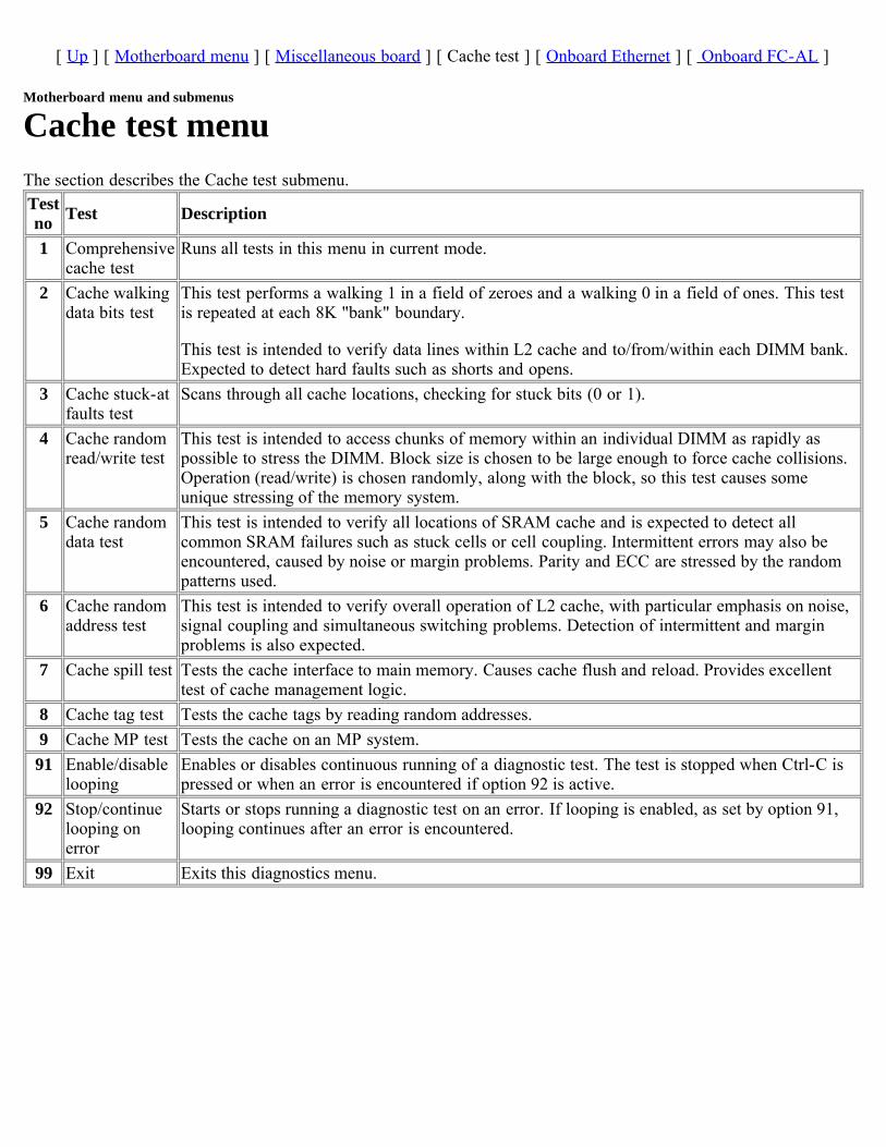
[ Up ] [ Motherboard menu ] [ Miscellaneous board ] [ Cache test ] [ Onboard Ethernet ] [ Onboard FC-AL ]
Motherboard menu and submenus
Cache test menuThe section describes the Cache test submenu.Testno Test Description
1 Comprehensivecache test
Runs all tests in this menu in current mode.
2 Cache walkingdata bits test
This test performs a walking 1 in a field of zeroes and a walking 0 in a field of ones. This testis repeated at each 8K "bank" boundary.
This test is intended to verify data lines within L2 cache and to/from/within each DIMM bank.Expected to detect hard faults such as shorts and opens.
3 Cache stuck-atfaults test
Scans through all cache locations, checking for stuck bits (0 or 1).
4 Cache randomread/write test
This test is intended to access chunks of memory within an individual DIMM as rapidly aspossible to stress the DIMM. Block size is chosen to be large enough to force cache collisions.Operation (read/write) is chosen randomly, along with the block, so this test causes someunique stressing of the memory system.
5 Cache randomdata test
This test is intended to verify all locations of SRAM cache and is expected to detect allcommon SRAM failures such as stuck cells or cell coupling. Intermittent errors may also beencountered, caused by noise or margin problems. Parity and ECC are stressed by the randompatterns used.
6 Cache randomaddress test
This test is intended to verify overall operation of L2 cache, with particular emphasis on noise,signal coupling and simultaneous switching problems. Detection of intermittent and marginproblems is also expected.
7 Cache spill test Tests the cache interface to main memory. Causes cache flush and reload. Provides excellenttest of cache management logic.
8 Cache tag test Tests the cache tags by reading random addresses.9 Cache MP test Tests the cache on an MP system.91 Enable/disable
loopingEnables or disables continuous running of a diagnostic test. The test is stopped when Ctrl-C ispressed or when an error is encountered if option 92 is active.
92 Stop/continuelooping onerror
Starts or stops running a diagnostic test on an error. If looping is enabled, as set by option 91,looping continues after an error is encountered.
99 Exit Exits this diagnostics menu.
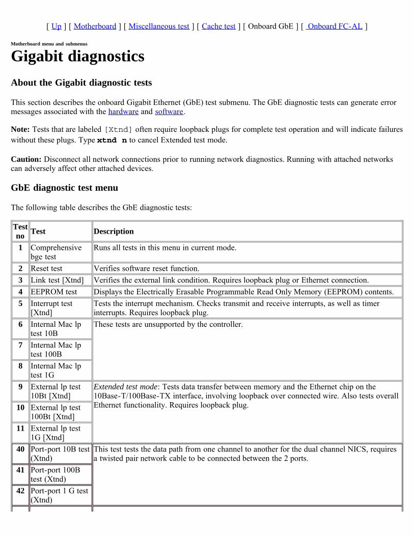
[ Up ] [ Motherboard ] [ Miscellaneous test ] [ Cache test ] [ Onboard GbE ] [ Onboard FC-AL ]
Motherboard menu and submenus
Gigabit diagnosticsAbout the Gigabit diagnostic tests
This section describes the onboard Gigabit Ethernet (GbE) test submenu. The GbE diagnostic tests can generate errormessages associated with the hardware and software.
Note: Tests that are labeled [Xtnd] often require loopback plugs for complete test operation and will indicate failureswithout these plugs. Type xtnd n to cancel Extended test mode.
Caution: Disconnect all network connections prior to running network diagnostics. Running with attached networkscan adversely affect other attached devices.
GbE diagnostic test menu
The following table describes the GbE diagnostic tests:
Testno Test Description
1 Comprehensivebge test
Runs all tests in this menu in current mode.
2 Reset test Verifies software reset function.3 Link test [Xtnd] Verifies the external link condition. Requires loopback plug or Ethernet connection.4 EEPROM test Displays the Electrically Erasable Programmable Read Only Memory (EEPROM) contents.5 Interrupt test
[Xtnd]Tests the interrupt mechanism. Checks transmit and receive interrupts, as well as timerinterrupts. Requires loopback plug.
6 Internal Mac lptest 10B
These tests are unsupported by the controller.
7 Internal Mac lptest 100B
8 Internal Mac lptest 1G
9 External lp test10Bt [Xtnd]
Extended test mode: Tests data transfer between memory and the Ethernet chip on the10Base-T/100Base-TX interface, involving loopback over connected wire. Also tests overallEthernet functionality. Requires loopback plug.10 External lp test
100Bt [Xtnd]11 External lp test
1G [Xtnd]40 Port-port 10B test
(Xtnd)This test tests the data path from one channel to another for the dual channel NICS, requiresa twisted pair network cable to be connected between the 2 ports.
41 Port-port 100Btest (Xtnd)
42 Port-port 1 G test(Xtnd)
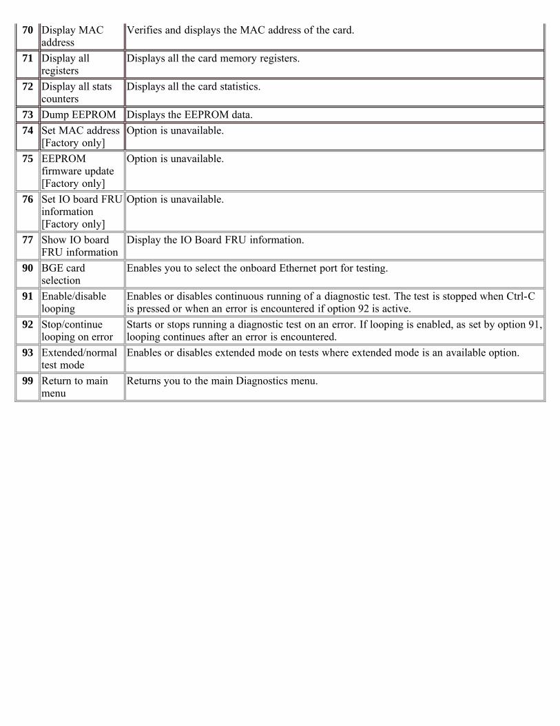
70 Display MACaddress
Verifies and displays the MAC address of the card.
71 Display allregisters
Displays all the card memory registers.
72 Display all statscounters
Displays all the card statistics.
73 Dump EEPROM Displays the EEPROM data.74 Set MAC address
[Factory only]Option is unavailable.
75 EEPROMfirmware update[Factory only]
Option is unavailable.
76 Set IO board FRUinformation[Factory only]
Option is unavailable.
77 Show IO boardFRU information
Display the IO Board FRU information.
90 BGE cardselection
Enables you to select the onboard Ethernet port for testing.
91 Enable/disablelooping
Enables or disables continuous running of a diagnostic test. The test is stopped when Ctrl-Cis pressed or when an error is encountered if option 92 is active.
92 Stop/continuelooping on error
Starts or stops running a diagnostic test on an error. If looping is enabled, as set by option 91,looping continues after an error is encountered.
93 Extended/normaltest mode
Enables or disables extended mode on tests where extended mode is an available option.
99 Return to mainmenu
Returns you to the main Diagnostics menu.

[ Up ] [ Motherboard ] [ Miscellaneous test ] [ Cache test ] [ Onboard GbE ] [ Onboard FC-AL ]
Motherboard menu and submenus
Onboard FC-AL diagnosticsThis section describes the onboard FC-AL (Fibre Channel Arbitrated Loop) group of diagnostics tests. The tests rangefrom EEPROM data verification through data transfer integrity testing. The FC-AL diagnostic tests can generate errormessages associated with the interface and disk shelf.
Note: To perform disk or shelf diagnostics, select test 90 and identify the channel. This returns you to the main FC-ALmenu. Then select test 80 or 81.
Caution: There are limitations to running Fibre Channel Diagnostics:
This test does not support switches, media changeres, connections to the SAN environment, and Fibre Channeladapters functioning in target mode.The external loopback test does not detect the presence or absence of a loopback device before running, nor doesit distinguish an open loop or broken cable. For example, the external loopback test fails if no loopback isattached. Users are responsible for correctly attaching the loopback device, and enabling external loopback tests.
Running diagnostics on a Multipath High Availability nodes: If you are running tests 41, 42, 73 or option 4 of test81 on a node in a Multi Path High Availability cabled pair of nodes, verify that one of the following is true:
The partner node is at the CFE or Loader boot prompt.The partner node is powered off.The multipath high availability cabling for both nodes has been removed such that the appliance is onlyresponsible for its own storage and not that of its partner.
FC-AL diagnostic test menu
Note: Tests that are labeled [Xtnd] often require loopback plugs for complete test operation and will indicate failureswithout these plugs. Type xtnd n to cancel Extended test mode.
Caution: Disconnect all network connections prior to running network diagnostics. Running with attached networkscan adversely affect other attached devices.
The following table describes the available tests in the FC-AL diagnostic menu:
Testno Test Description
1 ComprehensiveFCAL test
Runs all tests in this menu in current mode.
2 Self test Verifies and tests the FC-AL chip configuration, firmware commands, mailboxes, status, errorinformation, the serial EEPROM data, the ISP power-on self-test (POST), the on-chipSSRAM with fixed and random patterns, the SSRAM/DMA of fixed and random patternsbetween SSRAM and most locations of main memory, and ISP firmware in SSRAM.
3 ISP interrupt test Verifies the device's ability to generate interrupts, and the system's ability to handle interruptscorrectly.
4 Int loop test Tests data movement between main memory and the FC-AL chip, using on-chip loopbackcapability for 10 bit and 1 bit.
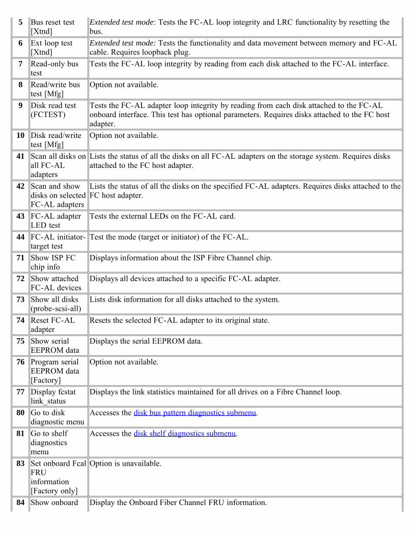
5 Bus reset test[Xtnd]
Extended test mode: Tests the FC-AL loop integrity and LRC functionality by resetting thebus.
6 Ext loop test[Xtnd]
Extended test mode: Tests the functionality and data movement between memory and FC-ALcable. Requires loopback plug.
7 Read-only bustest
Tests the FC-AL loop integrity by reading from each disk attached to the FC-AL interface.
8 Read/write bustest [Mfg]
Option not available.
9 Disk read test(FCTEST)
Tests the FC-AL adapter loop integrity by reading from each disk attached to the FC-ALonboard interface. This test has optional parameters. Requires disks attached to the FC hostadapter.
10 Disk read/writetest [Mfg]
Option not available.
41 Scan all disks onall FC-ALadapters
Lists the status of all the disks on all FC-AL adapters on the storage system. Requires disksattached to the FC host adapter.
42 Scan and showdisks on selectedFC-AL adapters
Lists the status of all the disks on the specified FC-AL adapters. Requires disks attached to theFC host adapter.
43 FC-AL adapterLED test
Tests the external LEDs on the FC-AL card.
44 FC-AL initiator-target test
Test the mode (target or initiator) of the FC-AL.
71 Show ISP FCchip info
Displays information about the ISP Fibre Channel chip.
72 Show attachedFC-AL devices
Displays all devices attached to a specific FC-AL adapter.
73 Show all disks(probe-scsi-all)
Lists disk information for all disks attached to the system.
74 Reset FC-ALadapter
Resets the selected FC-AL adapter to its original state.
75 Show serialEEPROM data
Displays the serial EEPROM data.
76 Program serialEEPROM data[Factory]
Option not available.
77 Display fcstatlink_status
Displays the link statistics maintained for all drives on a Fibre Channel loop.
80 Go to diskdiagnostic menu
Accesses the disk bus pattern diagnostics submenu.
81 Go to shelfdiagnosticsmenu
Accesses the disk shelf diagnostics submenu.
83 Set onboard FcalFRUinformation[Factory only]
Option is unavailable.
84 Show onboard Display the Onboard Fiber Channel FRU information.
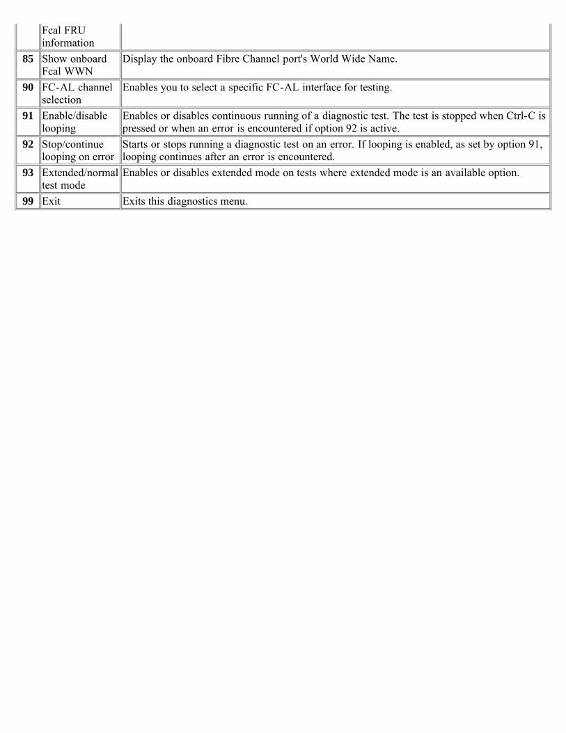
Fcal FRUinformation
85 Show onboardFcal WWN
Display the onboard Fibre Channel port's World Wide Name.
90 FC-AL channelselection
Enables you to select a specific FC-AL interface for testing.
91 Enable/disablelooping
Enables or disables continuous running of a diagnostic test. The test is stopped when Ctrl-C ispressed or when an error is encountered if option 92 is active.
92 Stop/continuelooping on error
Starts or stops running a diagnostic test on an error. If looping is enabled, as set by option 91,looping continues after an error is encountered.
93 Extended/normaltest mode
Enables or disables extended mode on tests where extended mode is an available option.
99 Exit Exits this diagnostics menu.

[ Up ] [ Disk diagnostics ] [ Disk shelf diagnostics ]
Card diagnostics
Disk diagnostics submenuThe following table describes the FC-AL disk diagnostics submenu:
Testno Test Description
1 Perform drive selfdiagnostic test
The drive seeks a reserved non user-accessible cylinder and writes, reads, andverifies data for each data surface.
2 Low frequency pattern[Mfg]
Option not available.
3 Low transition densitypattern [Mfg]
4 Half-rate square pattern[Mfg]
5 Quarter-rate squarepattern [Mfg]
6 Contiguous '3' pattern[Mfg]
7 Composite pattern [Mfg]40 Read drive defect list Displays primary and grown defect list. This test has optional parameters. Requires
disks attached to the FC host adapter.99 Exit this menu Returns the user to the main FC-AL menu.
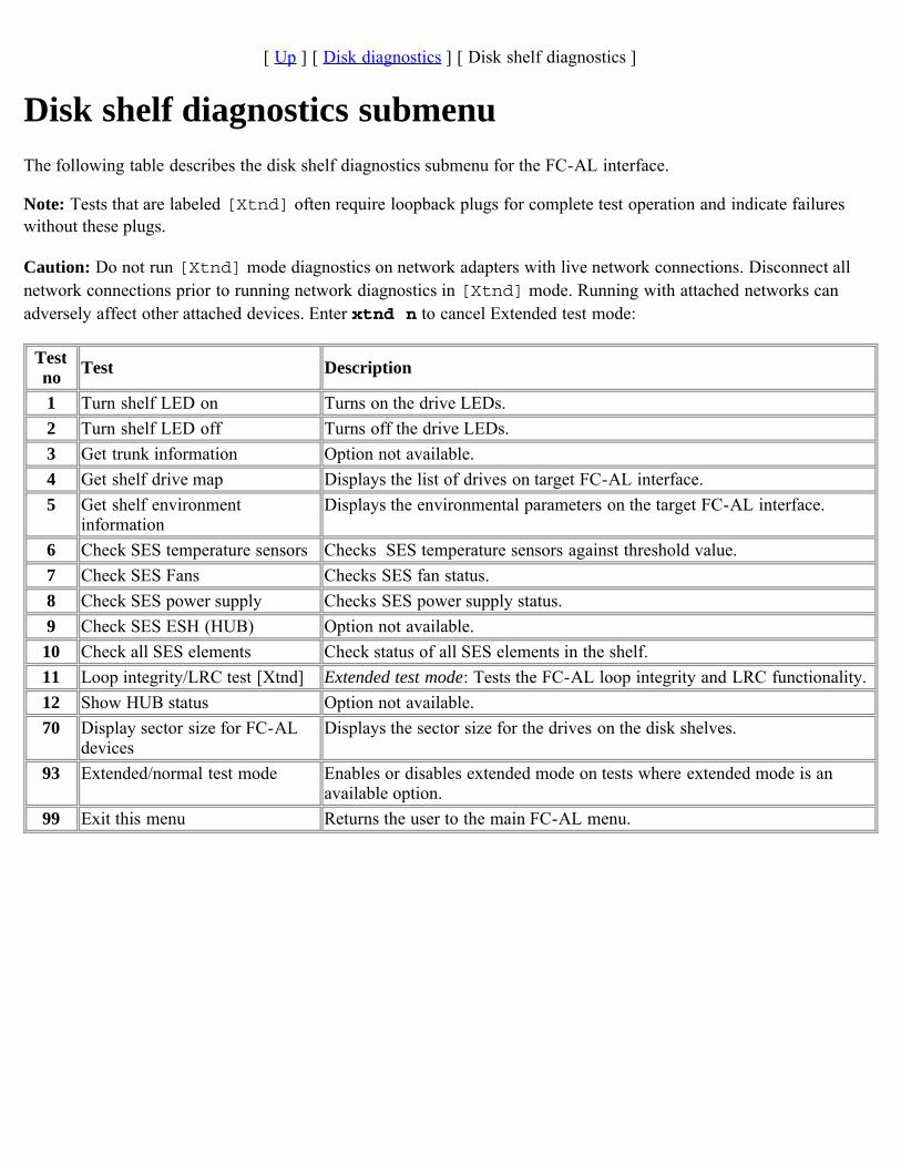
[ Up ] [ Disk diagnostics ] [ Disk shelf diagnostics ]
Disk shelf diagnostics submenuThe following table describes the disk shelf diagnostics submenu for the FC-AL interface.
Note: Tests that are labeled [Xtnd] often require loopback plugs for complete test operation and indicate failureswithout these plugs.
Caution: Do not run [Xtnd] mode diagnostics on network adapters with live network connections. Disconnect allnetwork connections prior to running network diagnostics in [Xtnd] mode. Running with attached networks canadversely affect other attached devices. Enter xtnd n to cancel Extended test mode:
Testno Test Description
1 Turn shelf LED on Turns on the drive LEDs.2 Turn shelf LED off Turns off the drive LEDs.3 Get trunk information Option not available.4 Get shelf drive map Displays the list of drives on target FC-AL interface.5 Get shelf environment
informationDisplays the environmental parameters on the target FC-AL interface.
6 Check SES temperature sensors Checks SES temperature sensors against threshold value.7 Check SES Fans Checks SES fan status.8 Check SES power supply Checks SES power supply status.9 Check SES ESH (HUB) Option not available.
10 Check all SES elements Check status of all SES elements in the shelf.11 Loop integrity/LRC test [Xtnd] Extended test mode: Tests the FC-AL loop integrity and LRC functionality.12 Show HUB status Option not available.70 Display sector size for FC-AL
devicesDisplays the sector size for the drives on the disk shelves.
93 Extended/normal test mode Enables or disables extended mode on tests where extended mode is anavailable option.
99 Exit this menu Returns the user to the main FC-AL menu.
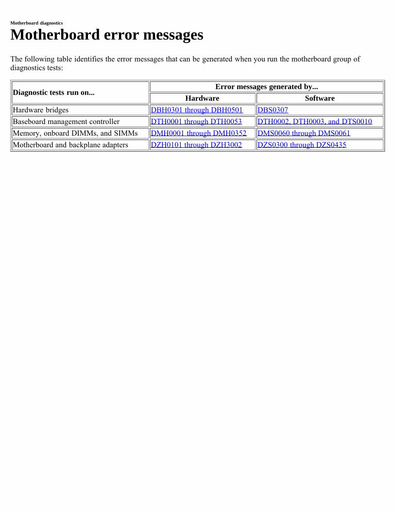
Motherboard diagnostics
Motherboard error messagesThe following table identifies the error messages that can be generated when you run the motherboard group ofdiagnostics tests:
Diagnostic tests run on...Error messages generated by...
Hardware SoftwareHardware bridges DBH0301 through DBH0501 DBS0307Baseboard management controller DTH0001 through DTH0053 DTH0002, DTH0003, and DTS0010Memory, onboard DIMMs, and SIMMs DMH0001 through DMH0352 DMS0060 through DMS0061Motherboard and backplane adapters DZH0101 through DZH3002 DZS0300 through DZS0435
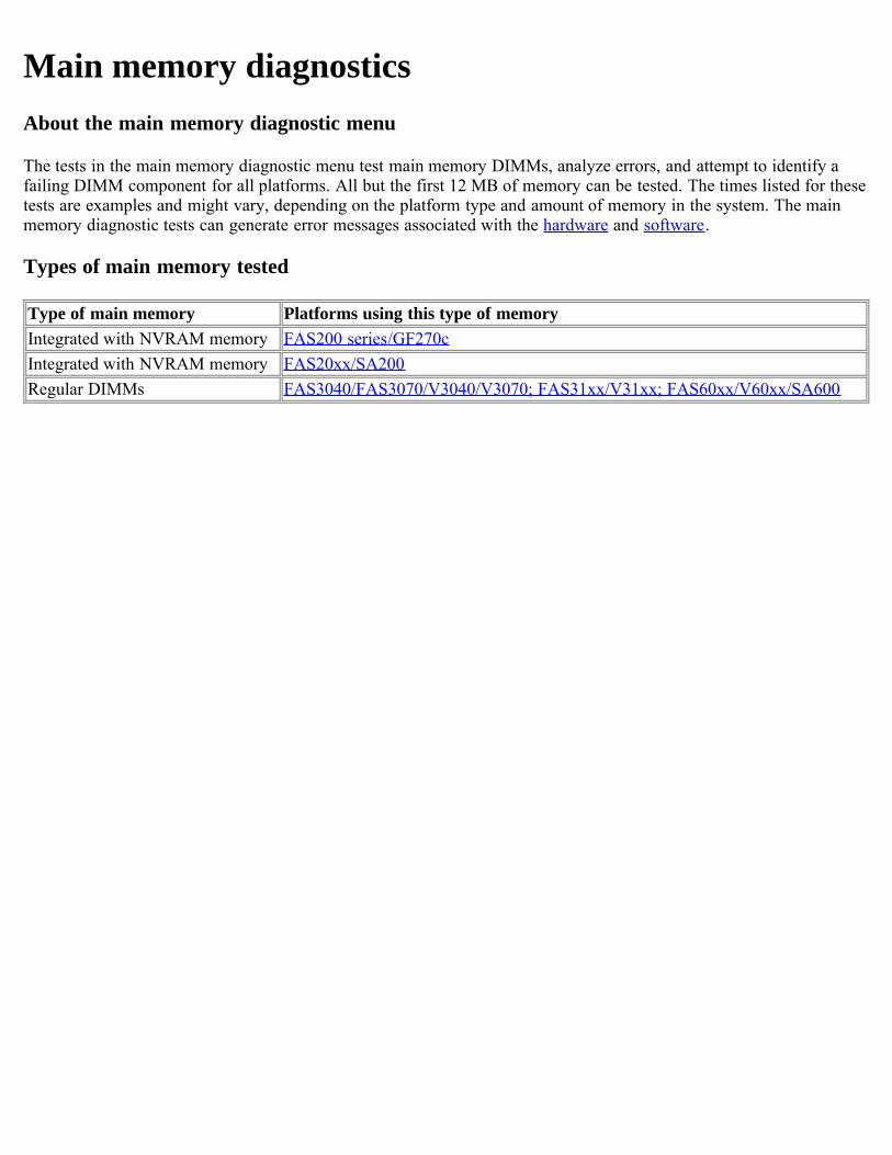
Main memory diagnosticsAbout the main memory diagnostic menu
The tests in the main memory diagnostic menu test main memory DIMMs, analyze errors, and attempt to identify afailing DIMM component for all platforms. All but the first 12 MB of memory can be tested. The times listed for thesetests are examples and might vary, depending on the platform type and amount of memory in the system. The mainmemory diagnostic tests can generate error messages associated with the hardware and software.
Types of main memory tested
Type of main memory Platforms using this type of memoryIntegrated with NVRAM memory FAS200 series/GF270cIntegrated with NVRAM memory FAS20xx/SA200Regular DIMMs FAS3040/FAS3070/V3040/V3070; FAS31xx/V31xx; FAS60xx/V60xx/SA600
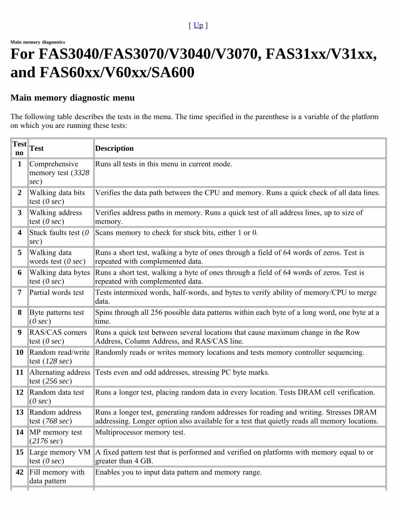
[ Up ]
Main memory diagnostics
For FAS3040/FAS3070/V3040/V3070, FAS31xx/V31xx,and FAS60xx/V60xx/SA600Main memory diagnostic menu
The following table describes the tests in the menu. The time specified in the parenthese is a variable of the platformon which you are running these tests:
Testno Test Description
1 Comprehensivememory test (3328sec)
Runs all tests in this menu in current mode.
2 Walking data bitstest (0 sec)
Verifies the data path between the CPU and memory. Runs a quick check of all data lines.
3 Walking addresstest (0 sec)
Verifies address paths in memory. Runs a quick test of all address lines, up to size ofmemory.
4 Stuck faults test (0sec)
Scans memory to check for stuck bits, either 1 or 0.
5 Walking datawords test (0 sec)
Runs a short test, walking a byte of ones through a field of 64 words of zeros. Test isrepeated with complemented data.
6 Walking data bytestest (0 sec)
Runs a short test, walking a byte of ones through a field of 64 words of zeros. Test isrepeated with complemented data.
7 Partial words test Tests intermixed words, half-words, and bytes to verify ability of memory/CPU to mergedata.
8 Byte patterns test(0 sec)
Spins through all 256 possible data patterns within each byte of a long word, one byte at atime.
9 RAS/CAS cornerstest (0 sec)
Runs a quick test between several locations that cause maximum change in the RowAddress, Column Address, and RAS/CAS line.
10 Random read/writetest (128 sec)
Randomly reads or writes memory locations and tests memory controller sequencing.
11 Alternating addresstest (256 sec)
Tests even and odd addresses, stressing PC byte marks.
12 Random data test(0 sec)
Runs a longer test, placing random data in every location. Tests DRAM cell verification.
13 Random addresstest (768 sec)
Runs a longer test, generating random addresses for reading and writing. Stresses DRAMaddressing. Longer option also available for a test that quietly reads all memory locations.
14 MP memory test(2176 sec)
Multiprocessor memory test.
15 Large memory VMtest (0 sec)
A fixed pattern test that is performed and verified on platforms with memory equal to orgreater than 4 GB.
42 Fill memory withdata pattern
Enables you to input data pattern and memory range.
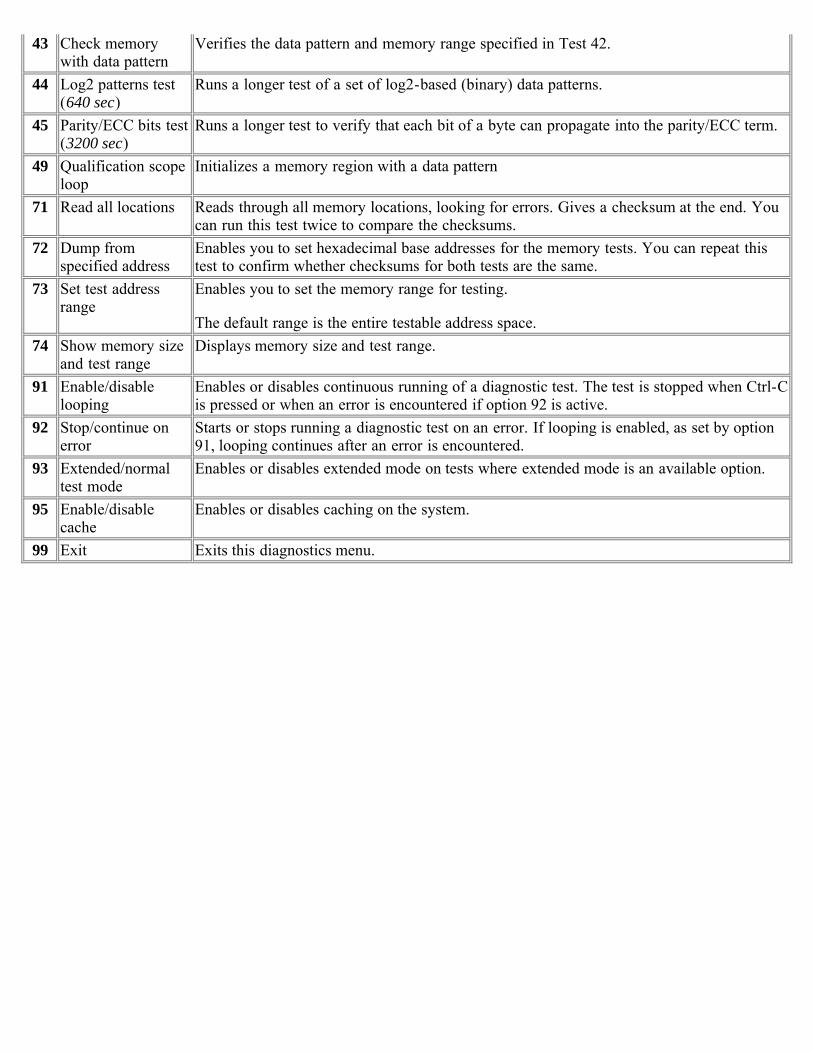
43 Check memorywith data pattern
Verifies the data pattern and memory range specified in Test 42.
44 Log2 patterns test(640 sec)
Runs a longer test of a set of log2-based (binary) data patterns.
45 Parity/ECC bits test(3200 sec)
Runs a longer test to verify that each bit of a byte can propagate into the parity/ECC term.
49 Qualification scopeloop
Initializes a memory region with a data pattern
71 Read all locations Reads through all memory locations, looking for errors. Gives a checksum at the end. Youcan run this test twice to compare the checksums.
72 Dump fromspecified address
Enables you to set hexadecimal base addresses for the memory tests. You can repeat thistest to confirm whether checksums for both tests are the same.
73 Set test addressrange
Enables you to set the memory range for testing.
The default range is the entire testable address space.74 Show memory size
and test rangeDisplays memory size and test range.
91 Enable/disablelooping
Enables or disables continuous running of a diagnostic test. The test is stopped when Ctrl-Cis pressed or when an error is encountered if option 92 is active.
92 Stop/continue onerror
Starts or stops running a diagnostic test on an error. If looping is enabled, as set by option91, looping continues after an error is encountered.
93 Extended/normaltest mode
Enables or disables extended mode on tests where extended mode is an available option.
95 Enable/disablecache
Enables or disables caching on the system.
99 Exit Exits this diagnostics menu.
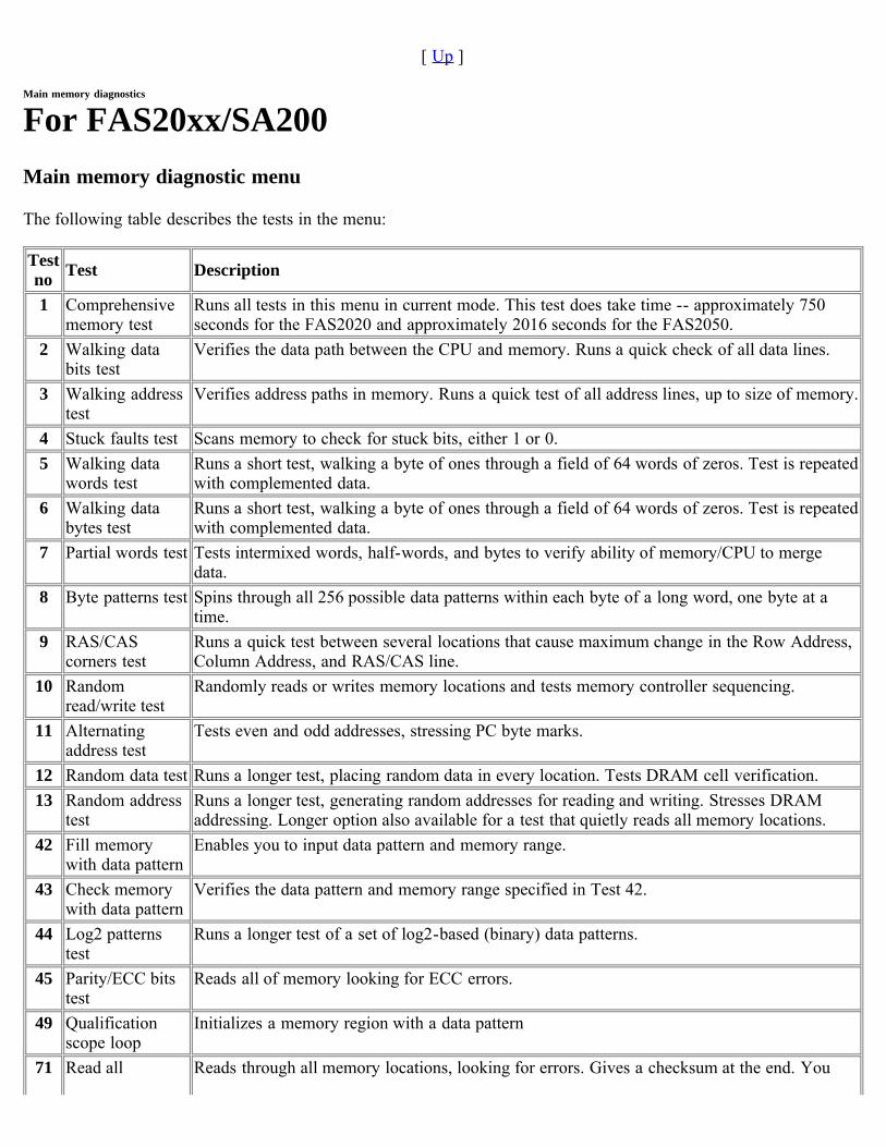
[ Up ]
Main memory diagnostics
For FAS20xx/SA200Main memory diagnostic menu
The following table describes the tests in the menu:
Testno Test Description
1 Comprehensivememory test
Runs all tests in this menu in current mode. This test does take time -- approximately 750seconds for the FAS2020 and approximately 2016 seconds for the FAS2050.
2 Walking databits test
Verifies the data path between the CPU and memory. Runs a quick check of all data lines.
3 Walking addresstest
Verifies address paths in memory. Runs a quick test of all address lines, up to size of memory.
4 Stuck faults test Scans memory to check for stuck bits, either 1 or 0.5 Walking data
words testRuns a short test, walking a byte of ones through a field of 64 words of zeros. Test is repeatedwith complemented data.
6 Walking databytes test
Runs a short test, walking a byte of ones through a field of 64 words of zeros. Test is repeatedwith complemented data.
7 Partial words test Tests intermixed words, half-words, and bytes to verify ability of memory/CPU to mergedata.
8 Byte patterns test Spins through all 256 possible data patterns within each byte of a long word, one byte at atime.
9 RAS/CAScorners test
Runs a quick test between several locations that cause maximum change in the Row Address,Column Address, and RAS/CAS line.
10 Randomread/write test
Randomly reads or writes memory locations and tests memory controller sequencing.
11 Alternatingaddress test
Tests even and odd addresses, stressing PC byte marks.
12 Random data test Runs a longer test, placing random data in every location. Tests DRAM cell verification.13 Random address
testRuns a longer test, generating random addresses for reading and writing. Stresses DRAMaddressing. Longer option also available for a test that quietly reads all memory locations.
42 Fill memorywith data pattern
Enables you to input data pattern and memory range.
43 Check memorywith data pattern
Verifies the data pattern and memory range specified in Test 42.
44 Log2 patternstest
Runs a longer test of a set of log2-based (binary) data patterns.
45 Parity/ECC bitstest
Reads all of memory looking for ECC errors.
49 Qualificationscope loop
Initializes a memory region with a data pattern
71 Read all Reads through all memory locations, looking for errors. Gives a checksum at the end. You
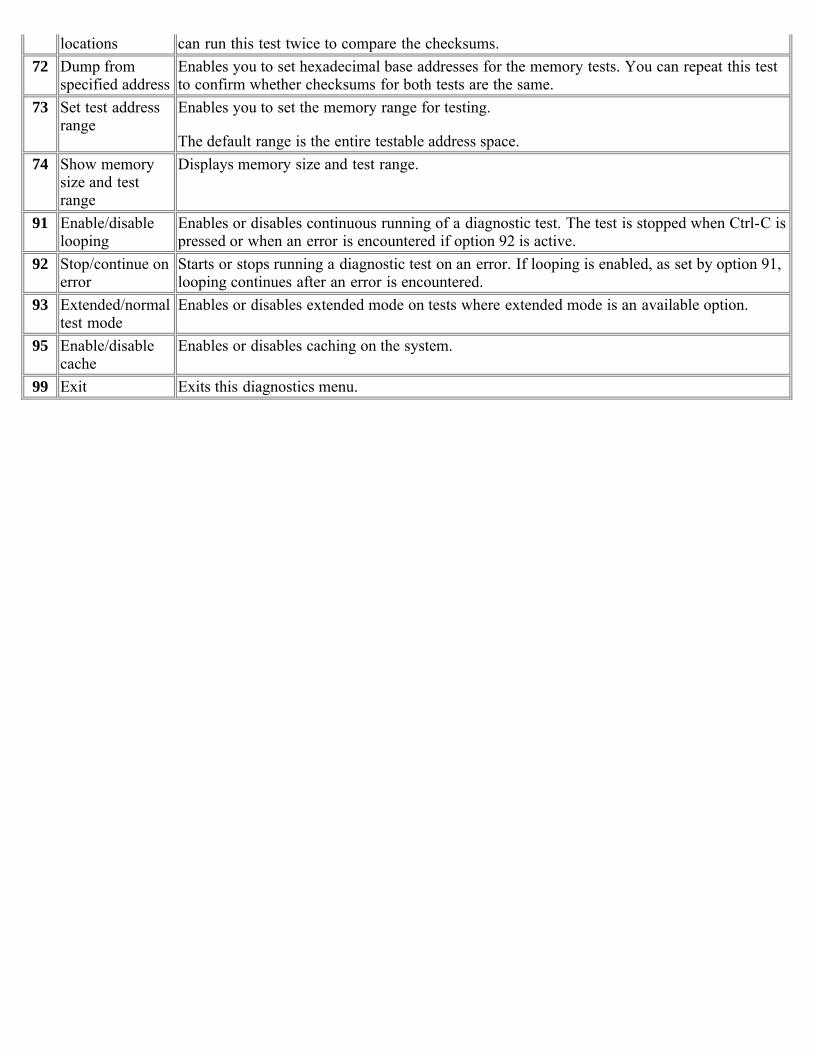
locations can run this test twice to compare the checksums.72 Dump from
specified addressEnables you to set hexadecimal base addresses for the memory tests. You can repeat this testto confirm whether checksums for both tests are the same.
73 Set test addressrange
Enables you to set the memory range for testing.
The default range is the entire testable address space.74 Show memory
size and testrange
Displays memory size and test range.
91 Enable/disablelooping
Enables or disables continuous running of a diagnostic test. The test is stopped when Ctrl-C ispressed or when an error is encountered if option 92 is active.
92 Stop/continue onerror
Starts or stops running a diagnostic test on an error. If looping is enabled, as set by option 91,looping continues after an error is encountered.
93 Extended/normaltest mode
Enables or disables extended mode on tests where extended mode is an available option.
95 Enable/disablecache
Enables or disables caching on the system.
99 Exit Exits this diagnostics menu.
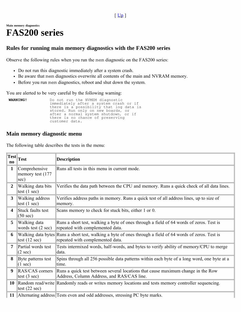
[ Up ]
Main memory diagnostics
FAS200 seriesRules for running main memory diagnostics with the FAS200 series
Observe the following rules when you run the mem diagnostic on the FAS200 series:
Do not run this diagnostic immediately after a system crash.Be aware that mem diagnostics overwrite all contents of the main and NVRAM memory.Before you run mem diagnostics, reboot and shut down the system.
You are alerted to be very careful by the following warning:WARNING! Do not run the NVMEM diagnostic
immediately after a system crash or if there is a possibility that log data is stored. Run only on new boards, or after a normal system shutdown, or if there is no chance of preserving customer data.
Main memory diagnostic menu
The following table describes the tests in the menu:
Testno Test Description
1 Comprehensivememory test (177sec)
Runs all tests in this menu in current mode.
2 Walking data bitstest (1 sec)
Verifies the data path between the CPU and memory. Runs a quick check of all data lines.
3 Walking addresstest (1 sec)
Verifies address paths in memory. Runs a quick test of all address lines, up to size ofmemory.
4 Stuck faults test(50 sec)
Scans memory to check for stuck bits, either 1 or 0.
5 Walking datawords test (2 sec)
Runs a short test, walking a byte of ones through a field of 64 words of zeros. Test isrepeated with complemented data.
6 Walking data bytestest (12 sec)
Runs a short test, walking a byte of ones through a field of 64 words of zeros. Test isrepeated with complemented data.
7 Partial words test(2 sec)
Tests intermixed words, half-words, and bytes to verify ability of memory/CPU to mergedata.
8 Byte patterns test(1 sec)
Spins through all 256 possible data patterns within each byte of a long word, one byte at atime.
9 RAS/CAS cornerstest (3 sec)
Runs a quick test between several locations that cause maximum change in the RowAddress, Column Address, and RAS/CAS line.
10 Random read/writetest (22 sec)
Randomly reads or writes memory locations and tests memory controller sequencing.
11 Alternating address Tests even and odd addresses, stressing PC byte marks.
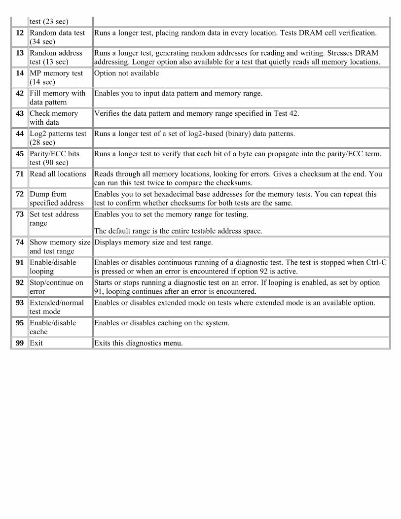
test (23 sec)12 Random data test
(34 sec)Runs a longer test, placing random data in every location. Tests DRAM cell verification.
13 Random addresstest (13 sec)
Runs a longer test, generating random addresses for reading and writing. Stresses DRAMaddressing. Longer option also available for a test that quietly reads all memory locations.
14 MP memory test(14 sec)
Option not available
42 Fill memory withdata pattern
Enables you to input data pattern and memory range.
43 Check memorywith data
Verifies the data pattern and memory range specified in Test 42.
44 Log2 patterns test(28 sec)
Runs a longer test of a set of log2-based (binary) data patterns.
45 Parity/ECC bitstest (90 sec)
Runs a longer test to verify that each bit of a byte can propagate into the parity/ECC term.
71 Read all locations Reads through all memory locations, looking for errors. Gives a checksum at the end. Youcan run this test twice to compare the checksums.
72 Dump fromspecified address
Enables you to set hexadecimal base addresses for the memory tests. You can repeat thistest to confirm whether checksums for both tests are the same.
73 Set test addressrange
Enables you to set the memory range for testing.
The default range is the entire testable address space.74 Show memory size
and test rangeDisplays memory size and test range.
91 Enable/disablelooping
Enables or disables continuous running of a diagnostic test. The test is stopped when Ctrl-Cis pressed or when an error is encountered if option 92 is active.
92 Stop/continue onerror
Starts or stops running a diagnostic test on an error. If looping is enabled, as set by option91, looping continues after an error is encountered.
93 Extended/normaltest mode
Enables or disables extended mode on tests where extended mode is an available option.
95 Enable/disablecache
Enables or disables caching on the system.
99 Exit Exits this diagnostics menu.
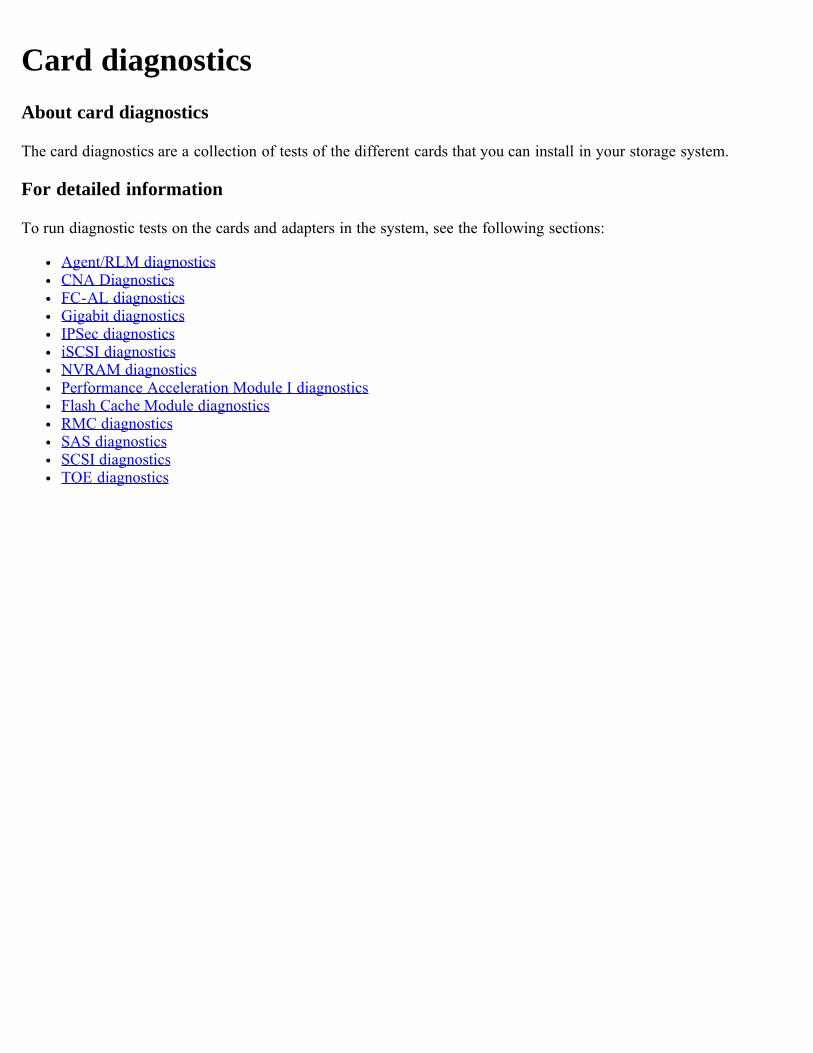
Card diagnosticsAbout card diagnostics
The card diagnostics are a collection of tests of the different cards that you can install in your storage system.
For detailed information
To run diagnostic tests on the cards and adapters in the system, see the following sections:
Agent/RLM diagnosticsCNA DiagnosticsFC-AL diagnosticsGigabit diagnosticsIPSec diagnosticsiSCSI diagnosticsNVRAM diagnosticsPerformance Acceleration Module I diagnosticsFlash Cache Module diagnosticsRMC diagnosticsSAS diagnosticsSCSI diagnosticsTOE diagnostics
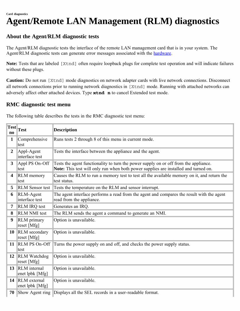
Card diagnostics
Agent/Remote LAN Management (RLM) diagnosticsAbout the Agent/RLM diagnostic tests
The Agent/RLM diagnostic tests the interface of the remote LAN management card that is in your system. TheAgent/RLM diagnostic tests can generate error messages associated with the hardware.
Note: Tests that are labeled [Xtnd] often require loopback plugs for complete test operation and will indicate failureswithout these plugs.
Caution: Do not run [Xtnd] mode diagnostics on network adapter cards with live network connections. Disconnectall network connections prior to running network diagnostics in [Xtnd] mode. Running with attached networks canadversely affect other attached devices. Type xtnd n to cancel Extended test mode.
RMC diagnostic test menu
The following table describes the tests in the RMC diagnostic test menu:
Testno Test Description
1 Comprehensivetest
Runs tests 2 through 8 of this menu in current mode.
2 Appl-Agentinterface test
Tests the interface between the appliance and the agent.
3 Appl PS On-Offtest
Tests the agent functionality to turn the power supply on or off from the appliance. Note: This test will only run when both power supplies are installed and turned on.
4 RLM memorytest
Causes the RLM to run a memory test to test all the available memory on it, and return thetest status.
5 RLM Sensor test Tests the temperature on the RLM and sensor interrupt.6 RLM-Agent
interface testThe agent interface performs a read from the agent and compares the result with the agentread from the appliance.
7 RLM IRQ test Generates an IRQ.8 RLM NMI test The RLM sends the agent a command to generate an NMI.9 RLM primary
reset [Mfg]Option is unavailable.
10 RLM secondaryreset [Mfg]
Option is unavailable.
11 RLM PS On-Offtest
Turns the power supply on and off, and checks the power supply status.
12 RLM Watchdogreset [Mfg]
Option is unavailable.
13 RLM internalenet lpbk [Mfg]
Option is unavailable.
14 RLM externalenet lpbk [Mfg]
Option is unavailable.
70 Show Agent ring Displays all the SEL records in a user-readable format.
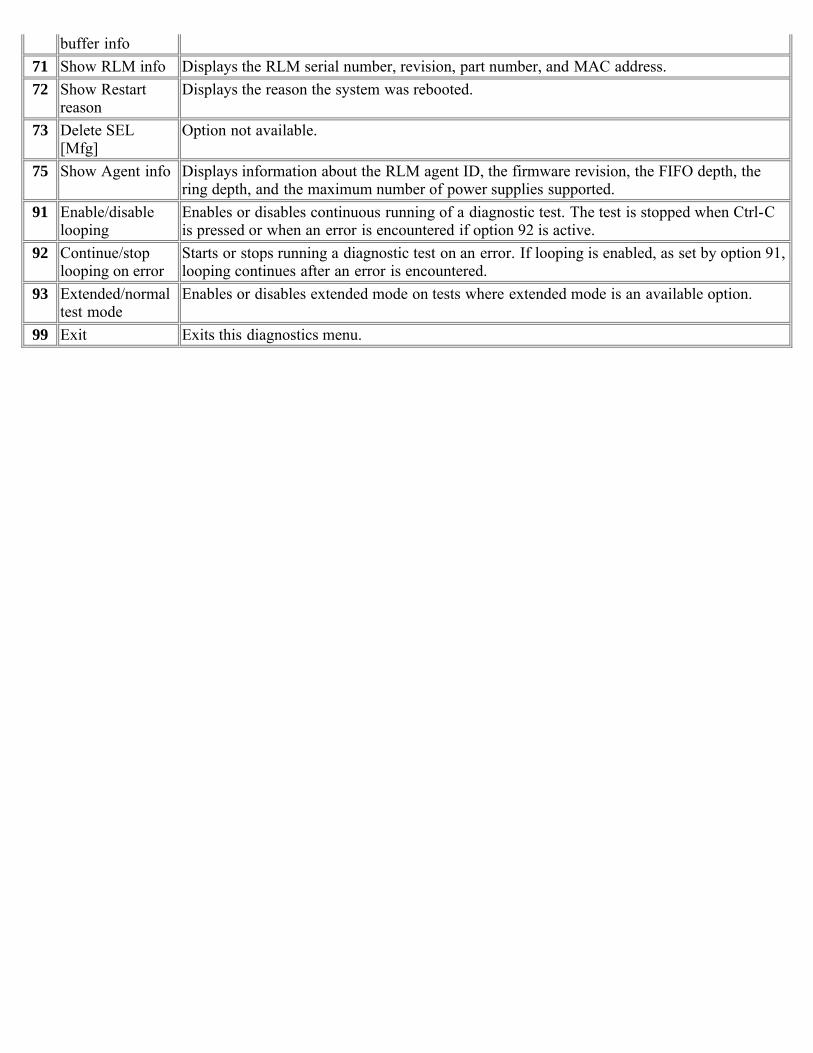
buffer info71 Show RLM info Displays the RLM serial number, revision, part number, and MAC address.72 Show Restart
reasonDisplays the reason the system was rebooted.
73 Delete SEL[Mfg]
Option not available.
75 Show Agent info Displays information about the RLM agent ID, the firmware revision, the FIFO depth, thering depth, and the maximum number of power supplies supported.
91 Enable/disablelooping
Enables or disables continuous running of a diagnostic test. The test is stopped when Ctrl-Cis pressed or when an error is encountered if option 92 is active.
92 Continue/stoplooping on error
Starts or stops running a diagnostic test on an error. If looping is enabled, as set by option 91,looping continues after an error is encountered.
93 Extended/normaltest mode
Enables or disables extended mode on tests where extended mode is an available option.
99 Exit Exits this diagnostics menu.
Card diagnostics
Converged Network Adapter diagnosticsAbout the converged network adapter diagnostic test menu
The converged network adapter (CNA) group of diagnostics test the functioning of the adapter that is in your system.The tests range from a status check of the adapter to the testing of data movement through the adapter.
Types of CNA cards tested:
Fibre ChannelEthernet
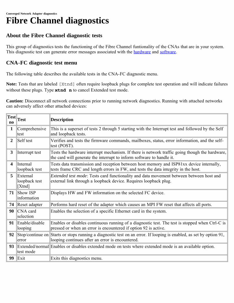
Converged Network Adapter diagnostics
Fibre Channel diagnosticsAbout the Fibre Channel diagnostic tests
This group of diagnostics tests the functioning of the Fibre Channel funtionality of the CNAs that are in your system.This diagnostic test can generate error messages associated with the hardware and software.
CNA-FC diagnostic test menu
The following table describes the available tests in the CNA-FC diagnostic menu.
Note: Tests that are labeled [Xtnd] often require loopback plugs for complete test operation and will indicate failureswithout these plugs. Type xtnd n to cancel Extended test mode.
Caution: Disconnect all network connections prior to running network diagnostics. Running with attached networkscan adversely affect other attached devices:
Testno Test Description
1 Comprehensivetest
This is a superset of tests 2 through 5 starting with the Interrupt test and followed by the Selfand loopback tests.
2 Self test Verifies and tests the firmware commands, mailboxes, status, error information, and the self-test (POST).
3 Interrupt test Tests the hardware interrupt mechanism. If there is network traffic going though the hardware,the card will generate the interrupt to inform software to handle it.
4 Internalloopback test
Tests data transmission and reception between host memory and ISP81xx device internally,tests frame CRC and length errors in FW, and tests the data integrity in the host.
5 Externalloopback test[Xtnd]
Extended test mode: Tests card functionality and data movement between between host andexternal link through a loopback device. Requires loopback plug.
71 Show ISPinformation
Displays HW and FW information on the selected FC device.
74 Reset adapter Performs hard reset of the adapter which causes an MPI FW reset that affects all ports.90 CNA card
selectionEnables the selection of a specific Ethernet card in the system.
91 Enable/disablelooping
Enables or disables continuous running of a diagnostic test. The test is stopped when Ctrl-C ispressed or when an error is encountered if option 92 is active.
92 Stop/continue onerror
Starts or stops running a diagnostic test on an error. If looping is enabled, as set by option 91,looping continues after an error is encountered.
93 Extended/normaltest mode
Enables or disables extended mode on tests where extended mode is an available option.
99 Exit Exits this diagnostics menu.
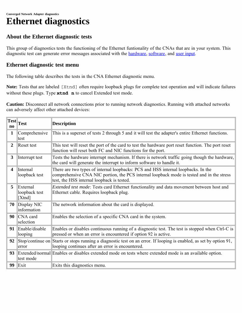
Converged Network Adapter diagnostics
Ethernet diagnosticsAbout the Ethernet diagnostic tests
This group of diagnostics tests the functioning of the Ethernet funtionality of the CNAs that are in your system. Thisdiagnostic test can generate error messages associated with the hardware, software, and user input.
Ethernet diagnostic test menu
The following table describes the tests in the CNA Ethernet diagnostic menu.
Note: Tests that are labeled [Xtnd] often require loopback plugs for complete test operation and will indicate failureswithout these plugs. Type xtnd n to cancel Extended test mode.
Caution: Disconnect all network connections prior to running network diagnostics. Running with attached networkscan adversely affect other attached devices:
Testno Test Description
1 Comprehensivetest
This is a superset of tests 2 through 5 and it will test the adapter's entire Ethernet functions.
2 Reset test This test will reset the port of the card to test the hardware port reset function. The port resetfunction will reset both FC and NIC functions for the port.
3 Interrupt test Tests the hardware interrupt mechanism. If there is network traffic going though the hardware,the card will generate the interrupt to inform software to handle it.
4 Internalloopback test
There are two types of internal loopbacks: PCS and HSS internal loopbacks. In thecomprehensive CNA NIC portion, the PCS internal loopback mode is tested and in the stresstest, the HSS internal loopback is tested.
5 Externalloopback test[Xtnd]
Extended test mode: Tests card Ethernet functionality and data movement between host andEthernet cable. Requires loopback plug.
70 Display NICinformation
The network information about the card is displayed.
90 CNA cardselection
Enables the selection of a specific CNA card in the system.
91 Enable/disablelooping
Enables or disables continuous running of a diagnostic test. The test is stopped when Ctrl-C ispressed or when an error is encountered if option 92 is active.
92 Stop/continue onerror
Starts or stops running a diagnostic test on an error. If looping is enabled, as set by option 91,looping continues after an error is encountered.
93 Extended/normaltest mode
Enables or disables extended mode on tests where extended mode is an available option.
99 Exit Exits this diagnostics menu.
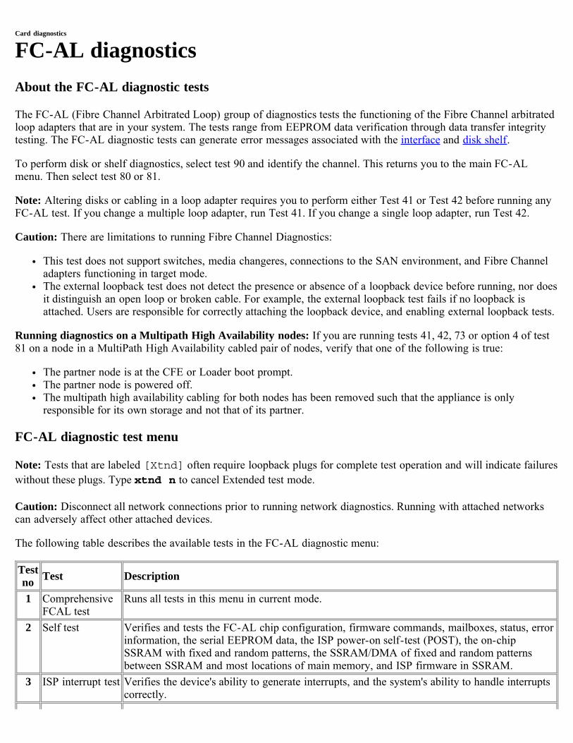
Card diagnostics
FC-AL diagnosticsAbout the FC-AL diagnostic tests
The FC-AL (Fibre Channel Arbitrated Loop) group of diagnostics tests the functioning of the Fibre Channel arbitratedloop adapters that are in your system. The tests range from EEPROM data verification through data transfer integritytesting. The FC-AL diagnostic tests can generate error messages associated with the interface and disk shelf.
To perform disk or shelf diagnostics, select test 90 and identify the channel. This returns you to the main FC-ALmenu. Then select test 80 or 81.
Note: Altering disks or cabling in a loop adapter requires you to perform either Test 41 or Test 42 before running anyFC-AL test. If you change a multiple loop adapter, run Test 41. If you change a single loop adapter, run Test 42.
Caution: There are limitations to running Fibre Channel Diagnostics:
This test does not support switches, media changeres, connections to the SAN environment, and Fibre Channeladapters functioning in target mode.The external loopback test does not detect the presence or absence of a loopback device before running, nor doesit distinguish an open loop or broken cable. For example, the external loopback test fails if no loopback isattached. Users are responsible for correctly attaching the loopback device, and enabling external loopback tests.
Running diagnostics on a Multipath High Availability nodes: If you are running tests 41, 42, 73 or option 4 of test81 on a node in a MultiPath High Availability cabled pair of nodes, verify that one of the following is true:
The partner node is at the CFE or Loader boot prompt.The partner node is powered off.The multipath high availability cabling for both nodes has been removed such that the appliance is onlyresponsible for its own storage and not that of its partner.
FC-AL diagnostic test menu
Note: Tests that are labeled [Xtnd] often require loopback plugs for complete test operation and will indicate failureswithout these plugs. Type xtnd n to cancel Extended test mode.
Caution: Disconnect all network connections prior to running network diagnostics. Running with attached networkscan adversely affect other attached devices.
The following table describes the available tests in the FC-AL diagnostic menu:
Testno Test Description
1 ComprehensiveFCAL test
Runs all tests in this menu in current mode.
2 Self test Verifies and tests the FC-AL chip configuration, firmware commands, mailboxes, status, errorinformation, the serial EEPROM data, the ISP power-on self-test (POST), the on-chipSSRAM with fixed and random patterns, the SSRAM/DMA of fixed and random patternsbetween SSRAM and most locations of main memory, and ISP firmware in SSRAM.
3 ISP interrupt test Verifies the device's ability to generate interrupts, and the system's ability to handle interruptscorrectly.
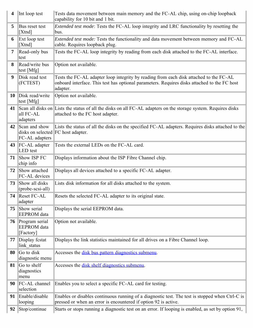
4 Int loop test Tests data movement between main memory and the FC-AL chip, using on-chip loopbackcapability for 10 bit and 1 bit.
5 Bus reset test[Xtnd]
Extended test mode: Tests the FC-AL loop integrity and LRC functionality by resetting thebus.
6 Ext loop test[Xtnd]
Extended test mode: Tests the functionality and data movement between memory and FC-ALcable. Requires loopback plug.
7 Read-only bustest
Tests the FC-AL loop integrity by reading from each disk attached to the FC-AL interface.
8 Read/write bustest [Mfg]
Option not available.
9 Disk read test(FCTEST)
Tests the FC-AL adapter loop integrity by reading from each disk attached to the FC-ALonboard interface. This test has optional parameters. Requires disks attached to the FC hostadapter.
10 Disk read/writetest [Mfg]
Option not available.
41 Scan all disks onall FC-ALadapters
Lists the status of all the disks on all FC-AL adapters on the storage system. Requires disksattached to the FC host adapter.
42 Scan and showdisks on selectedFC-AL adapters
Lists the status of all the disks on the specified FC-AL adapters. Requires disks attached to theFC host adapter.
43 FC-AL adapterLED test
Tests the external LEDs on the FC-AL card.
71 Show ISP FCchip info
Displays information about the ISP Fibre Channel chip.
72 Show attachedFC-AL devices
Displays all devices attached to a specific FC-AL adapter.
73 Show all disks(probe-scsi-all)
Lists disk information for all disks attached to the system.
74 Reset FC-ALadapter
Resets the selected FC-AL adapter to its original state.
75 Show serialEEPROM data
Displays the serial EEPROM data.
76 Program serialEEPROM data[Factory]
Option not available.
77 Display fcstatlink_status
Displays the link statistics maintained for all drives on a Fibre Channel loop.
80 Go to diskdiagnostic menu
Accesses the disk bus pattern diagnostics submenu.
81 Go to shelfdiagnosticsmenu
Accesses the disk shelf diagnostics submenu.
90 FC-AL channelselection
Enables you to select a specific FC-AL card for testing.
91 Enable/disablelooping
Enables or disables continuous running of a diagnostic test. The test is stopped when Ctrl-C ispressed or when an error is encountered if option 92 is active.
92 Stop/continue Starts or stops running a diagnostic test on an error. If looping is enabled, as set by option 91,

looping on error looping continues after an error is encountered.93 Extended/normal
test modeEnables or disables extended mode on tests where extended mode is an available option.
99 Exit Exits this diagnostics menu.

[ Up ] [ Disk diagnostics ] [ Disk shelf diagnostics ]
Card diagnostics
Disk diagnostics submenuThe following table describes the FC-AL disk diagnostics submenu:
Testno Test Description
1 Perform drive selfdiagnostic test
The drive seeks a reserved non user-accessible cylinder and writes, reads, andverifies data for each data surface.
2 Low frequency pattern[Mfg]
Option not available.
3 Low transition densitypattern [Mfg]
4 Half-rate square pattern[Mfg]
5 Quarter-rate squarepattern [Mfg]
6 Contiguous '3' pattern[Mfg]
7 Composite pattern [Mfg]40 Read drive defect list Displays primary and grown defect list. This test has optional parameters. Requires
disks attached to the FC host adapter.99 Exit this menu Returns the user to the main FC-AL menu.
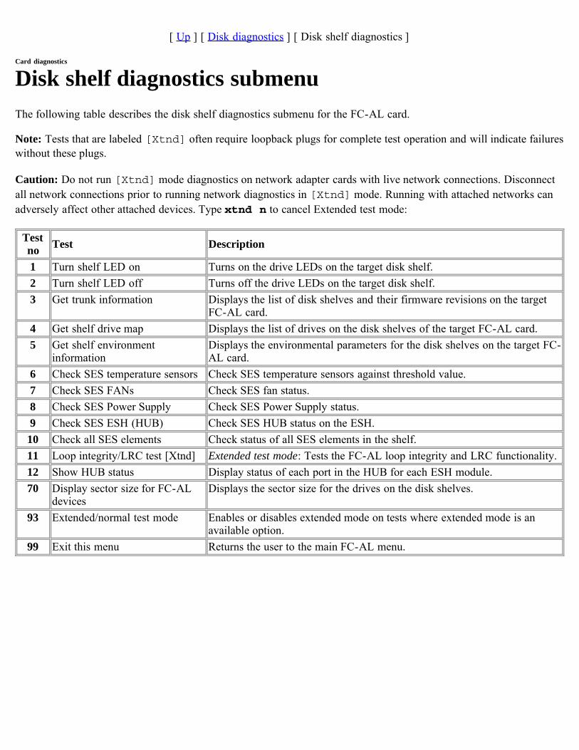
[ Up ] [ Disk diagnostics ] [ Disk shelf diagnostics ]
Card diagnostics
Disk shelf diagnostics submenuThe following table describes the disk shelf diagnostics submenu for the FC-AL card.
Note: Tests that are labeled [Xtnd] often require loopback plugs for complete test operation and will indicate failureswithout these plugs.
Caution: Do not run [Xtnd] mode diagnostics on network adapter cards with live network connections. Disconnectall network connections prior to running network diagnostics in [Xtnd] mode. Running with attached networks canadversely affect other attached devices. Type xtnd n to cancel Extended test mode:
Testno Test Description
1 Turn shelf LED on Turns on the drive LEDs on the target disk shelf.2 Turn shelf LED off Turns off the drive LEDs on the target disk shelf.3 Get trunk information Displays the list of disk shelves and their firmware revisions on the target
FC-AL card.4 Get shelf drive map Displays the list of drives on the disk shelves of the target FC-AL card.5 Get shelf environment
informationDisplays the environmental parameters for the disk shelves on the target FC-AL card.
6 Check SES temperature sensors Check SES temperature sensors against threshold value.7 Check SES FANs Check SES fan status.8 Check SES Power Supply Check SES Power Supply status.9 Check SES ESH (HUB) Check SES HUB status on the ESH.
10 Check all SES elements Check status of all SES elements in the shelf.11 Loop integrity/LRC test [Xtnd] Extended test mode: Tests the FC-AL loop integrity and LRC functionality.12 Show HUB status Display status of each port in the HUB for each ESH module.70 Display sector size for FC-AL
devicesDisplays the sector size for the drives on the disk shelves.
93 Extended/normal test mode Enables or disables extended mode on tests where extended mode is anavailable option.
99 Exit this menu Returns the user to the main FC-AL menu.
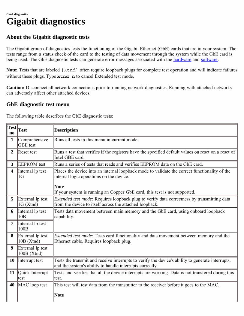
Card diagnostics
Gigabit diagnosticsAbout the Gigabit diagnostic tests
The Gigabit group of diagnostics tests the functioning of the Gigabit Ethernet (GbE) cards that are in your system. Thetests range from a status check of the card to the testing of data movement through the system while the GbE card isbeing used. The GbE diagnostic tests can generate error messages associated with the hardware and software.
Note: Tests that are labeled [Xtnd] often require loopback plugs for complete test operation and will indicate failureswithout these plugs. Type xtnd n to cancel Extended test mode.
Caution: Disconnect all network connections prior to running network diagnostics. Running with attached networkscan adversely affect other attached devices.
GbE diagnostic test menu
The following table describes the GbE diagnostic tests:
Testno Test Description
1 ComprehensiveGBE test
Runs all tests in this menu in current mode.
2 Reset test Runs a test that verifies if the registers have the specified default values on reset on a reset ofIntel GBE card.
3 EEPROM test Runs a series of tests that reads and verifies EEPROM data on the GbE card.4 Internal lp test
1GPlaces the device into an internal loopback mode to validate the correct functionality of theinternal logic operations on the device.
NoteIf your system is running an Copper GbE card, this test is not supported.
5 External lp test1G (Xtnd)
Extended test mode: Requires loopback plug to verify data correctness by transmitting datafrom the device to itself across the attached loopback.
6 Internal lp test10B
Tests data movement between main memory and the GbE card, using onboard loopbackcapability.
7 Internal lp test100B
8 External lp test10B (Xtnd)
Extended test mode: Tests card functionality and data movement between memory and theEthernet cable. Requires loopback plug.
9 External lp test100B (Xtnd)
10 Interrupt test Tests the transmit and receive interrupts to verify the device's ability to generate interrupts,and the system's ability to handle interrupts correctly.
11 Quick Interrupttest
Tests and verifies that all the device interrupts are working. Data is not transfered during thistest.
40 MAC loop test This test will test data from the transmitter to the receiver before it goes to the MAC.
Note
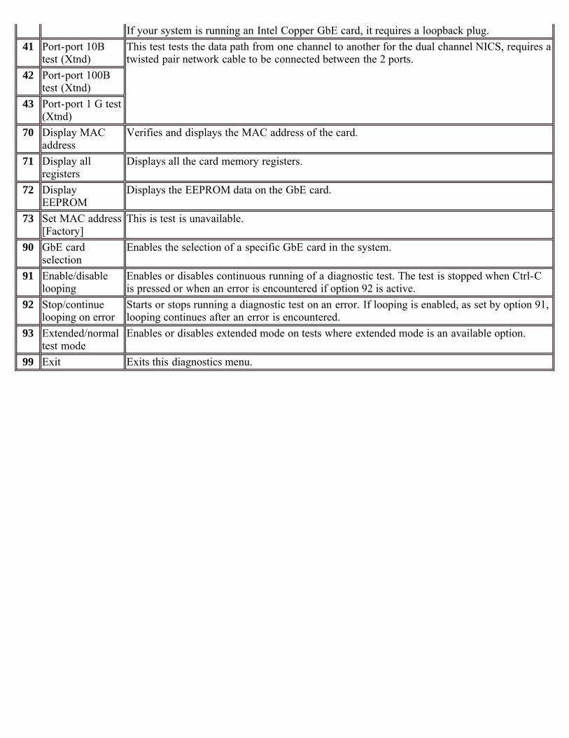
If your system is running an Intel Copper GbE card, it requires a loopback plug.41 Port-port 10B
test (Xtnd)This test tests the data path from one channel to another for the dual channel NICS, requires atwisted pair network cable to be connected between the 2 ports.
42 Port-port 100Btest (Xtnd)
43 Port-port 1 G test(Xtnd)
70 Display MACaddress
Verifies and displays the MAC address of the card.
71 Display allregisters
Displays all the card memory registers.
72 DisplayEEPROM
Displays the EEPROM data on the GbE card.
73 Set MAC address[Factory]
This is test is unavailable.
90 GbE cardselection
Enables the selection of a specific GbE card in the system.
91 Enable/disablelooping
Enables or disables continuous running of a diagnostic test. The test is stopped when Ctrl-Cis pressed or when an error is encountered if option 92 is active.
92 Stop/continuelooping on error
Starts or stops running a diagnostic test on an error. If looping is enabled, as set by option 91,looping continues after an error is encountered.
93 Extended/normaltest mode
Enables or disables extended mode on tests where extended mode is an available option.
99 Exit Exits this diagnostics menu.
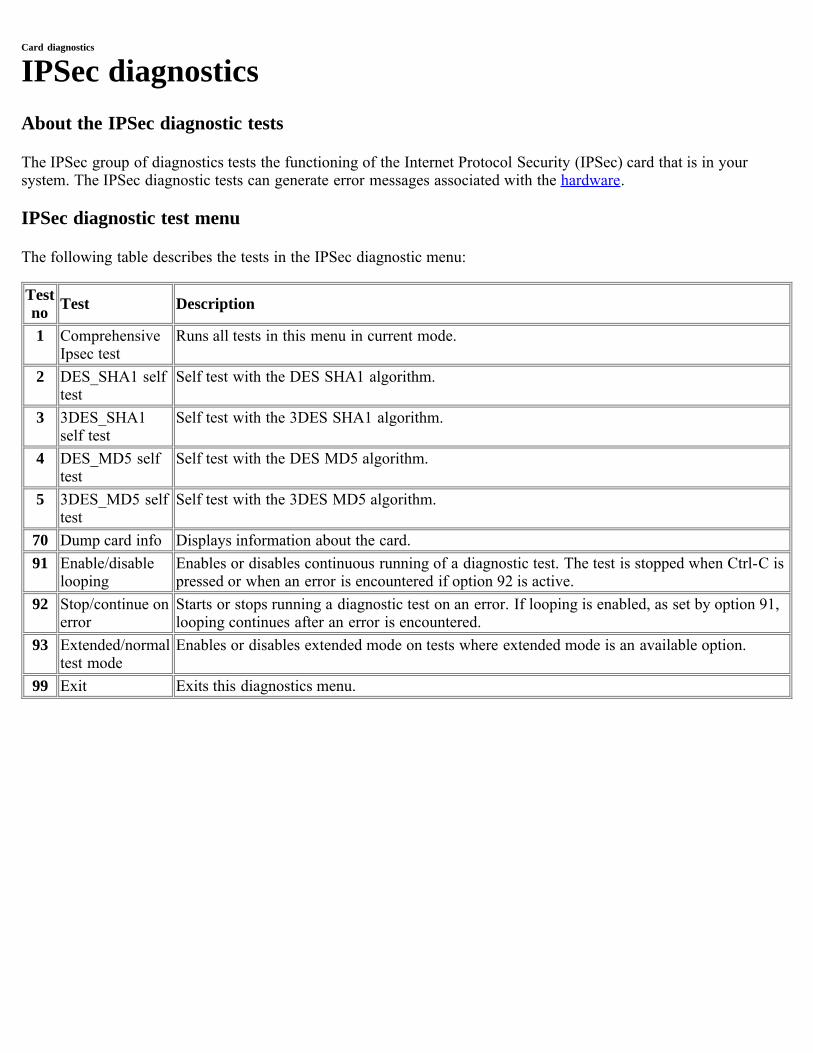
Card diagnostics
IPSec diagnosticsAbout the IPSec diagnostic tests
The IPSec group of diagnostics tests the functioning of the Internet Protocol Security (IPSec) card that is in yoursystem. The IPSec diagnostic tests can generate error messages associated with the hardware.
IPSec diagnostic test menu
The following table describes the tests in the IPSec diagnostic menu:
Testno Test Description
1 ComprehensiveIpsec test
Runs all tests in this menu in current mode.
2 DES_SHA1 selftest
Self test with the DES SHA1 algorithm.
3 3DES_SHA1self test
Self test with the 3DES SHA1 algorithm.
4 DES_MD5 selftest
Self test with the DES MD5 algorithm.
5 3DES_MD5 selftest
Self test with the 3DES MD5 algorithm.
70 Dump card info Displays information about the card.91 Enable/disable
loopingEnables or disables continuous running of a diagnostic test. The test is stopped when Ctrl-C ispressed or when an error is encountered if option 92 is active.
92 Stop/continue onerror
Starts or stops running a diagnostic test on an error. If looping is enabled, as set by option 91,looping continues after an error is encountered.
93 Extended/normaltest mode
Enables or disables extended mode on tests where extended mode is an available option.
99 Exit Exits this diagnostics menu.
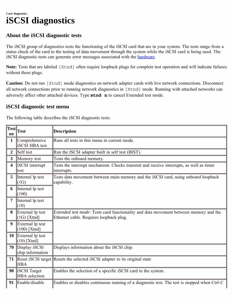
Card diagnostics
iSCSI diagnosticsAbout the iSCSI diagnostic tests
The iSCSI group of diagnostics tests the functioning of the iSCSI card that are in your system. The tests range from astatus check of the card to the testing of data movement through the system while the iSCSI card is being used. TheiSCSI diagnostic tests can generate error messages associated with the hardware.
Note: Tests that are labeled [Xtnd] often require loopback plugs for complete test operation and will indicate failureswithout these plugs.
Caution: Do not run [Xtnd] mode diagnostics on network adapter cards with live network connections. Disconnectall network connections prior to running network diagnostics in [Xtnd] mode. Running with attached networks canadversely affect other attached devices. Type xtnd n to cancel Extended test mode.
iSCSI diagnostic test menu
The following table describes the iSCSI diagnostic tests:
Testno Test Description
1 ComprehensiveiSCSI HBA test
Runs all tests in this menu in current mode.
2 Self test Run the ISCSI adapter built in self test (BIST).3 Memory test Tests the onboard memory.4 iSCSI interrupt
testTests the interrupt mechanism. Checks transmit and receive interrupts, as well as timerinterrupts.
5 Internal lp test(1G)
Tests data movement between main memory and the iSCSI card, using onboard loopbackcapability.
6 Internal lp test(100)
7 Internal lp test(10)
8 External lp test(1G) [Xtnd]
Extended test mode: Tests card functionality and data movement between memory and theEthernet cable. Requires loopback plug.
9 External lp test(100) [Xtnd]
10 External lp test(10) [Xtnd]
70 Display iSCSIchip information
Displays information about the iSCSI chip.
71 Reset iSCSI targetHBA
Resets the selected iSCSI adapter to its original state
90 iSCSI TargetHBA selection
Enables the selection of a specific iSCSI card in the system.
91 Enable/disable Enables or disables continuous running of a diagnostic test. The test is stopped when Ctrl-C
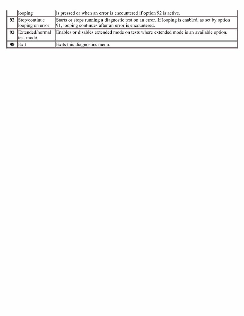
looping is pressed or when an error is encountered if option 92 is active.92 Stop/continue
looping on errorStarts or stops running a diagnostic test on an error. If looping is enabled, as set by option91, looping continues after an error is encountered.
93 Extended/normaltest mode
Enables or disables extended mode on tests where extended mode is an available option.
99 Exit Exits this diagnostics menu.
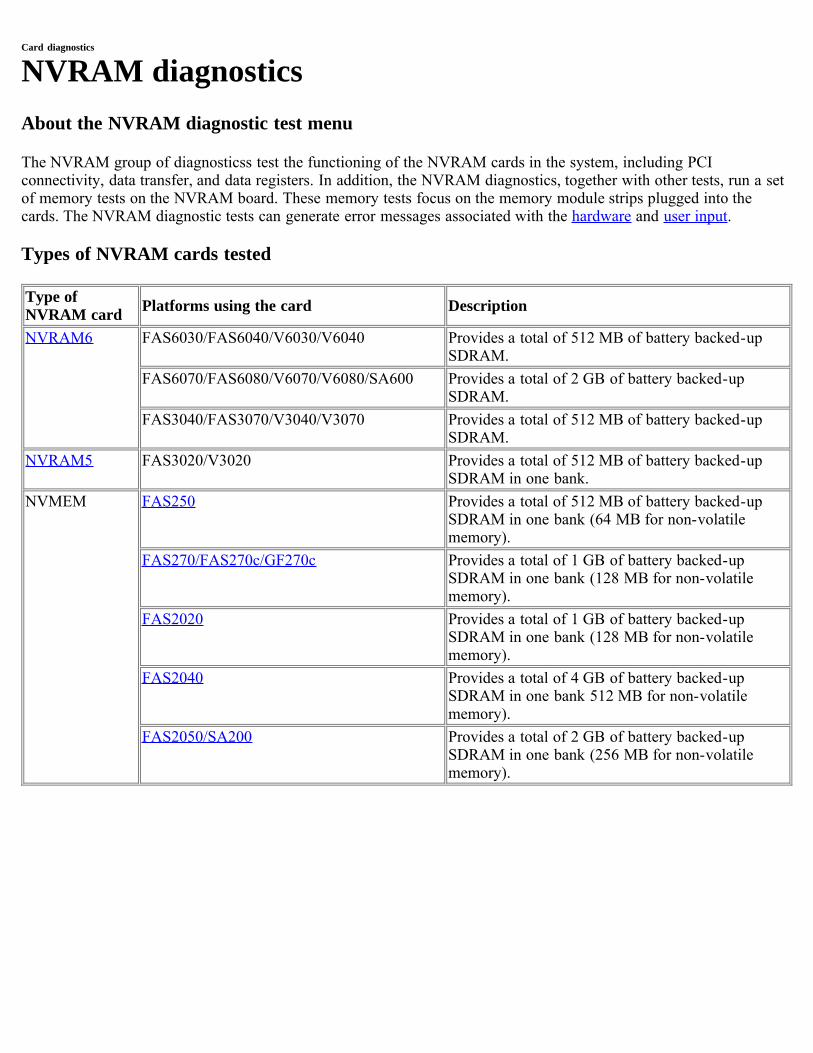
Card diagnostics
NVRAM diagnosticsAbout the NVRAM diagnostic test menu
The NVRAM group of diagnosticss test the functioning of the NVRAM cards in the system, including PCIconnectivity, data transfer, and data registers. In addition, the NVRAM diagnostics, together with other tests, run a setof memory tests on the NVRAM board. These memory tests focus on the memory module strips plugged into thecards. The NVRAM diagnostic tests can generate error messages associated with the hardware and user input.
Types of NVRAM cards tested
Type ofNVRAM card Platforms using the card Description
NVRAM6 FAS6030/FAS6040/V6030/V6040 Provides a total of 512 MB of battery backed-upSDRAM.
FAS6070/FAS6080/V6070/V6080/SA600 Provides a total of 2 GB of battery backed-upSDRAM.
FAS3040/FAS3070/V3040/V3070 Provides a total of 512 MB of battery backed-upSDRAM.
NVRAM5 FAS3020/V3020 Provides a total of 512 MB of battery backed-upSDRAM in one bank.
NVMEM FAS250 Provides a total of 512 MB of battery backed-upSDRAM in one bank (64 MB for non-volatilememory).
FAS270/FAS270c/GF270c Provides a total of 1 GB of battery backed-upSDRAM in one bank (128 MB for non-volatilememory).
FAS2020 Provides a total of 1 GB of battery backed-upSDRAM in one bank (128 MB for non-volatilememory).
FAS2040 Provides a total of 4 GB of battery backed-upSDRAM in one bank 512 MB for non-volatilememory).
FAS2050/SA200 Provides a total of 2 GB of battery backed-upSDRAM in one bank (256 MB for non-volatilememory).
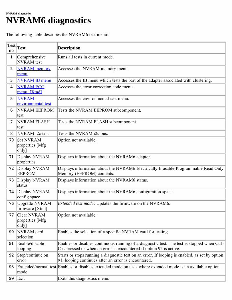
NVRAM diagnostics
NVRAM6 diagnosticsThe following table describes the NVRAM6 test menu:
Testno Test Description
1 ComprehensiveNVRAM test
Runs all tests in current mode.
2 NVRAM memorymenu
Accesses the NVRAM memory menu.
3 NVRAM IB menu Accesses the IB menu which tests the part of the adapter associated with clustering.4 NVRAM ECC
menu [Xtnd]Accesses the error correction code menu.
5 NVRAMenvironmental test
Accesses the environmental test menu.
6 NVRAM EEPROMtest
Tests the NVRAM EEPROM subcomponent.
7 NVRAM FLASHtest
Tests the NVRAM FLASH subcomponent.
8 NVRAM i2c test Tests the NVRAM i2c bus.70 Set NVRAM
properties [Mfgonly]
Option not available.
71 Display NVRAMproperties
Displays information about the NVRAM6 adapter.
72 Display NVRAMEEPROM
Displays information about the NVRAM6 Electrically Erasable Programmable Read OnlyMemory (EEPROM) contents.
73 Display NVRAMstatus
Displays information about the NVRAM6 status.
74 Display NVRAMconfig space
Displays information about the NVRAM6 configuration space.
76 Upgrade NVRAMfirmware [Xtnd]
Extended test mode: Updates the firmware on the NVRAM6.
77 Clear NVRAMproperties [Mfgonly]
Option not available.
90 NVRAM cardselection
Enables the selection of a specific NVRAM card for testing.
91 Enable/disablelooping
Enables or disables continuous running of a diagnostic test. The test is stopped when Ctrl-C is pressed or when an error is encountered if option 92 is active.
92 Stop/continue onerror
Starts or stops running a diagnostic test on an error. If looping is enabled, as set by option91, looping continues after an error is encountered.
93 Extended/normal testmode
Enables or disables extended mode on tests where extended mode is an available option.
99 Exit Exits this diagnostics menu.
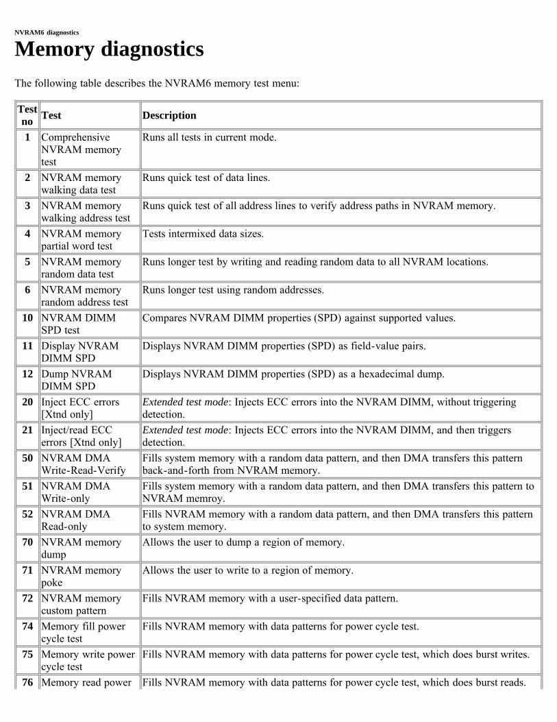
NVRAM6 diagnostics
Memory diagnosticsThe following table describes the NVRAM6 memory test menu:
Testno Test Description
1 ComprehensiveNVRAM memorytest
Runs all tests in current mode.
2 NVRAM memorywalking data test
Runs quick test of data lines.
3 NVRAM memorywalking address test
Runs quick test of all address lines to verify address paths in NVRAM memory.
4 NVRAM memorypartial word test
Tests intermixed data sizes.
5 NVRAM memoryrandom data test
Runs longer test by writing and reading random data to all NVRAM locations.
6 NVRAM memoryrandom address test
Runs longer test using random addresses.
10 NVRAM DIMMSPD test
Compares NVRAM DIMM properties (SPD) against supported values.
11 Display NVRAMDIMM SPD
Displays NVRAM DIMM properties (SPD) as field-value pairs.
12 Dump NVRAMDIMM SPD
Displays NVRAM DIMM properties (SPD) as a hexadecimal dump.
20 Inject ECC errors[Xtnd only]
Extended test mode: Injects ECC errors into the NVRAM DIMM, without triggeringdetection.
21 Inject/read ECCerrors [Xtnd only]
Extended test mode: Injects ECC errors into the NVRAM DIMM, and then triggersdetection.
50 NVRAM DMAWrite-Read-Verify
Fills system memory with a random data pattern, and then DMA transfers this patternback-and-forth from NVRAM memory.
51 NVRAM DMAWrite-only
Fills system memory with a random data pattern, and then DMA transfers this pattern toNVRAM memroy.
52 NVRAM DMARead-only
Fills NVRAM memory with a random data pattern, and then DMA transfers this patternto system memory.
70 NVRAM memorydump
Allows the user to dump a region of memory.
71 NVRAM memorypoke
Allows the user to write to a region of memory.
72 NVRAM memorycustom pattern
Fills NVRAM memory with a user-specified data pattern.
74 Memory fill powercycle test
Fills NVRAM memory with data patterns for power cycle test.
75 Memory write powercycle test
Fills NVRAM memory with data patterns for power cycle test, which does burst writes.
76 Memory read power Fills NVRAM memory with data patterns for power cycle test, which does burst reads.
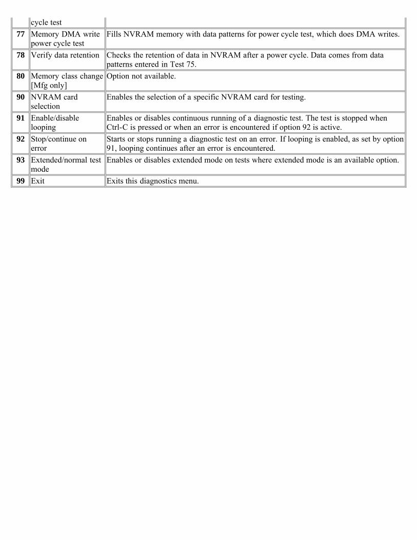
cycle test77 Memory DMA write
power cycle testFills NVRAM memory with data patterns for power cycle test, which does DMA writes.
78 Verify data retention Checks the retention of data in NVRAM after a power cycle. Data comes from datapatterns entered in Test 75.
80 Memory class change[Mfg only]
Option not available.
90 NVRAM cardselection
Enables the selection of a specific NVRAM card for testing.
91 Enable/disablelooping
Enables or disables continuous running of a diagnostic test. The test is stopped whenCtrl-C is pressed or when an error is encountered if option 92 is active.
92 Stop/continue onerror
Starts or stops running a diagnostic test on an error. If looping is enabled, as set by option91, looping continues after an error is encountered.
93 Extended/normal testmode
Enables or disables extended mode on tests where extended mode is an available option.
99 Exit Exits this diagnostics menu.
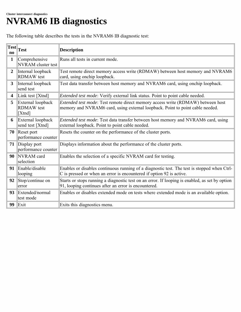
Cluster interconnect diagnostics
NVRAM6 IB diagnosticsThe following table describes the tests in the NVRAM6 IB diagnostic test:
Testno Test Description
1 ComprehensiveNVRAM cluster test
Runs all tests in current mode.
2 Internal loopbackRDMAW test
Test remote direct memory access write (RDMAW) between host memory and NVRAM6card, using onchip loopback.
3 Internal loopbacksend test
Test data transfer between host memory and NVRAM6 card, using onchip loopback.
4 Link test [Xtnd] Extended test mode: Verify external link status. Point to point cable needed. 5 External loopback
RDMAW test[Xtnd]
Extended test mode: Test remote direct memory access write (RDMAW) between hostmemory and NVRAM6 card, using external loopback. Point to point cable needed.
6 External loopbacksend test [Xtnd]
Extended test mode: Test data transfer between host memory and NVRAM6 card, usingexternal loopback. Point to point cable needed.
70 Reset portperformance counter
Resets the counter on the performance of the cluster ports.
71 Display portperformance counter
Displays information about the performance of the cluster ports.
90 NVRAM cardselection
Enables the selection of a specific NVRAM card for testing.
91 Enable/disablelooping
Enables or disables continuous running of a diagnostic test. The test is stopped when Ctrl-C is pressed or when an error is encountered if option 92 is active.
92 Stop/continue onerror
Starts or stops running a diagnostic test on an error. If looping is enabled, as set by option91, looping continues after an error is encountered.
93 Extended/normaltest mode
Enables or disables extended mode on tests where extended mode is an available option.
99 Exit Exits this diagnostics menu.

NVRAM6 diagnostics
Error Correction Code (ECC) diagnosticsThe following table describes the NVRAM6 ECC test menu:
Testno Test Description
1 ComprehensiveNVRAM ECC test
Runs all tests in current mode.
2 NVRAM ECCFIFO test
Tests the ECC FIFO that acts as a buffer.
3 NVRAM ECCmemory sweep
Tests that all of memory can be corrected.
70 Plant ECC error Inserts an ECC error into memory.71 Plant and read ECC
errorInserts an ECC error into memory and then reads memory, thereby causing a correction.
72 Wait for and printECC errors
Waits for ECC errors without causing them to occur.
73 System disablecommand
Issues a command to disable the InfiniBand interface. This happens by default whenentering the ECC menu.
74 System enablecommand
ssues a command to enable the InfiniBand interface.
90 NVRAM cardselection
Enables the selection of a specific NVRAM card for testing.
91 Enable/disablelooping
Enables or disables continuous running of a diagnostic test. The test is stopped when Ctrl-C is pressed or when an error is encountered if option 92 is active.
92 Stop/continue onerror
Starts or stops running a diagnostic test on an error. If looping is enabled, as set by option91, looping continues after an error is encountered.
93 Extended/normaltest mode
Enables or disables extended mode on tests where extended mode is an available option.
99 Exit Exits this diagnostics menu.
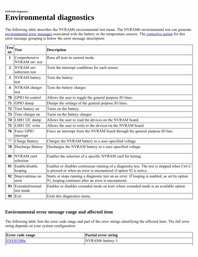
NVRAM6 diagnostics
Environmental diagnosticsThe following table describes the NVRAM6 environmental test menu. The NVRAM6 environmental test can generateenvironmental error messages associated with the battery or the temperature sensors. The corrective action for thiserror message grouping is below the error message description:
Testno Test Description
1 ComprehensiveNVRAM env test
Runs all tests in current mode.
2 NVRAM envsubsytem test
Tests the interrupt conditions for each sensor.
3 NVRAM batterytest
Tests the battery.
4 NVRAM chargertest
Tests the battery charger.
70 GPIO bit control Allows the user to toggle the general purpose IO lines.71 GPIO dump Dumps the settings of the general purpose IO lines.72 Turn battery on Turns on the battery.73 Turn charger on Turns on the battery charger.74 LM81 I2C dump Allows the user to read the devices on the NVRAM board.75 LM81 I2C write Allows the user to write to the devices on the NVRAM board.76 Force GPIO
interruptForce an interrupt from the NVRAM board through the general purpose IO line.
77 Charge Battery Charges the NVRAM battery to a user-specified voltage.78 Discharge Battery Discharges the NVRAM battery to a user-specified voltage.
90 NVRAM cardselection
Enables the selection of a specific NVRAM card for testing.
91 Enable/disablelooping
Enables or disables continuous running of a diagnostic test. The test is stopped when Ctrl-Cis pressed or when an error is encountered if option 92 is active.
92 Stop/continue onerror
Starts or stops running a diagnostic test on an error. If looping is enabled, as set by option91, looping continues after an error is encountered.
93 Extended/normaltest mode
Enables or disables extended mode on tests where extended mode is an available option.
99 Exit Exits this diagnostics menu.
Environmental error message range and affected item
The following table lists the error code range and part of the error strings identifying the affected item. The full errorstring depends on your system configuration:
Error code range Partial error stringENV01500x NVRAM6-battery-1
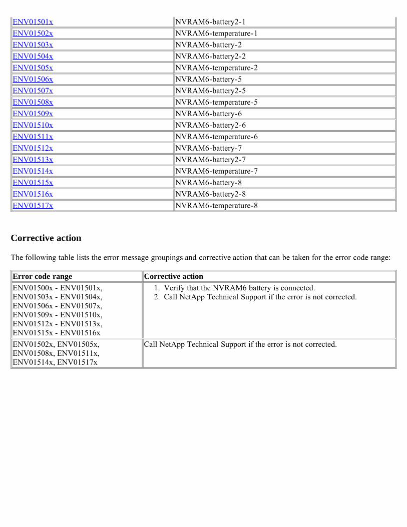
ENV01501x NVRAM6-battery2-1ENV01502x NVRAM6-temperature-1ENV01503x NVRAM6-battery-2ENV01504x NVRAM6-battery2-2ENV01505x NVRAM6-temperature-2ENV01506x NVRAM6-battery-5ENV01507x NVRAM6-battery2-5ENV01508x NVRAM6-temperature-5ENV01509x NVRAM6-battery-6ENV01510x NVRAM6-battery2-6ENV01511x NVRAM6-temperature-6ENV01512x NVRAM6-battery-7ENV01513x NVRAM6-battery2-7ENV01514x NVRAM6-temperature-7ENV01515x NVRAM6-battery-8ENV01516x NVRAM6-battery2-8ENV01517x NVRAM6-temperature-8
Corrective action
The following table lists the error message groupings and corrective action that can be taken for the error code range:
Error code range Corrective actionENV01500x - ENV01501x,ENV01503x - ENV01504x,ENV01506x - ENV01507x,ENV01509x - ENV01510x,ENV01512x - ENV01513x,ENV01515x - ENV01516x
1. Verify that the NVRAM6 battery is connected.2. Call NetApp Technical Support if the error is not corrected.
ENV01502x, ENV01505x, ENV01508x, ENV01511x, ENV01514x, ENV01517x
Call NetApp Technical Support if the error is not corrected.
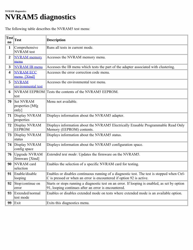
NVRAM diagnostics
NVRAM5 diagnosticsThe following table describes the NVRAM5 test menu:
Testno Test Description
1 ComprehensiveNVRAM test
Runs all tests in current mode.
2 NVRAM memorymenu
Accesses the NVRAM memory menu.
3 NVRAM IB menu Accesses the IB menu which tests the part of the adapter associated with clustering.4 NVRAM ECC
menu [Xtnd]Accesses the error correction code menu.
5 NVRAMenvironmental test
Accesses the environmental test menu.
6 NVRAM EEPROMtest
Tests the contents of the NVRAM5 EEPROM.
70 Set NVRAMproperties [Mfgonly]
Menu not available.
71 Display NVRAMproperties
Displays information about the NVRAM5 adapter.
72 Display NVRAMEEPROM
Displays information about the NVRAM5 Electrically Erasable Programmable Read OnlyMemory (EEPROM) contents.
73 Display NVRAMstatus
Displays information about the NVRAM5 status.
74 Display NVRAMconfig space
Displays information about the NVRAM5 configuration space.
76 Upgrade NVRAMfirmware [Xtnd]
Extended test mode: Updates the firmware on the NVRAM5.
90 NVRAM cardselection
Enables the selection of a specific NVRAM card for testing.
91 Enable/disablelooping
Enables or disables continuous running of a diagnostic test. The test is stopped when Ctrl-C is pressed or when an error is encountered if option 92 is active.
92 Stop/continue onerror
Starts or stops running a diagnostic test on an error. If looping is enabled, as set by option91, looping continues after an error is encountered.
93 Extended/normaltest mode
Enables or disables extended mode on tests where extended mode is an available option.
99 Exit Exits this diagnostics menu.
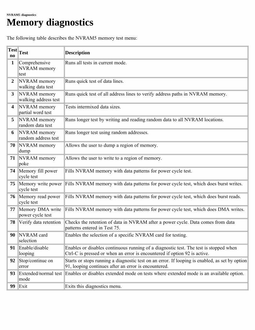
NVRAM5 diagnostics
Memory diagnosticsThe following table describes the NVRAM5 memory test menu:
Testno Test Description
1 ComprehensiveNVRAM memorytest
Runs all tests in current mode.
2 NVRAM memorywalking data test
Runs quick test of data lines.
3 NVRAM memorywalking address test
Runs quick test of all address lines to verify address paths in NVRAM memory.
4 NVRAM memorypartial word test
Tests intermixed data sizes.
5 NVRAM memoryrandom data test
Runs longer test by writing and reading random data to all NVRAM locations.
6 NVRAM memoryrandom address test
Runs longer test using random addresses.
70 NVRAM memorydump
Allows the user to dump a region of memory.
71 NVRAM memorypoke
Allows the user to write to a region of memory.
74 Memory fill powercycle test
Fills NVRAM memory with data patterns for power cycle test.
75 Memory write powercycle test
Fills NVRAM memory with data patterns for power cycle test, which does burst writes.
76 Memory read powercycle test
Fills NVRAM memory with data patterns for power cycle test, which does burst reads.
77 Memory DMA writepower cycle test
Fills NVRAM memory with data patterns for power cycle test, which does DMA writes.
78 Verify data retention Checks the retention of data in NVRAM after a power cycle. Data comes from datapatterns entered in Test 75.
90 NVRAM cardselection
Enables the selection of a specific NVRAM card for testing.
91 Enable/disablelooping
Enables or disables continuous running of a diagnostic test. The test is stopped whenCtrl-C is pressed or when an error is encountered if option 92 is active.
92 Stop/continue onerror
Starts or stops running a diagnostic test on an error. If looping is enabled, as set by option91, looping continues after an error is encountered.
93 Extended/normal testmode
Enables or disables extended mode on tests where extended mode is an available option.
99 Exit Exits this diagnostics menu.

Cluster interconnect diagnostics
NVRAM5 IB diagnosticsThe following table describes the tests in the NVRAM5 IB diagnostic test:
Testno Test Description
1 ComprehensiveNVRAM cluster test
Runs all tests in current mode.
2 Internal loopbackRDMAW test
Test remote direct memory access write (RDMAW) between host memory and NVRAM5card, using onchip loopback.
3 Internal loopbacksend test
Test data transfer between host memory and NVRAM5 card, using onchip loopback.
4 Link test [Xtnd] Extended test mode: Verify external link status. Point to point cable needed. 5 External loopback
RDMAW test[Xtnd]
Extended test mode: Test remote direct memory access write (RDMAW) between hostmemory and NVRAM5 card, using external loopback. Point to point cable needed.
6 External loopbacksend test [Xtnd]
Extended test mode: Test data transfer between host memory and NVRAM5 card, usingexternal loopback. Point to point cable needed.
70 Reset portperformance counter
Resets the counter on the performance of the cluster ports.
71 Display portperformance counter
Displays information about the performance of the cluster ports.
90 NVRAM cardselection
Enables the selection of a specific NVRAM card for testing.
91 Enable/disablelooping
Enables or disables continuous running of a diagnostic test. The test is stopped when Ctrl-C is pressed or when an error is encountered if option 92 is active.
92 Stop/continue onerror
Starts or stops running a diagnostic test on an error. If looping is enabled, as set by option91, looping continues after an error is encountered.
93 Extended/normaltest mode
Enables or disables extended mode on tests where extended mode is an available option.
99 Exit Exits this diagnostics menu.
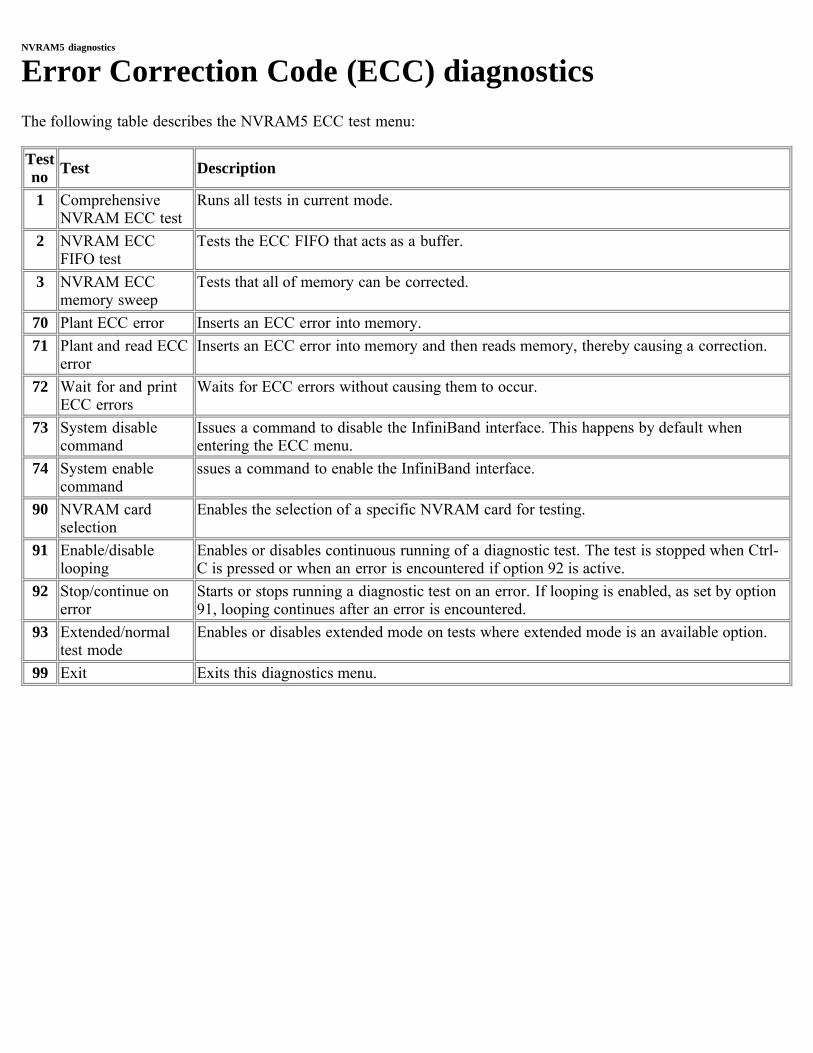
NVRAM5 diagnostics
Error Correction Code (ECC) diagnosticsThe following table describes the NVRAM5 ECC test menu:
Testno Test Description
1 ComprehensiveNVRAM ECC test
Runs all tests in current mode.
2 NVRAM ECCFIFO test
Tests the ECC FIFO that acts as a buffer.
3 NVRAM ECCmemory sweep
Tests that all of memory can be corrected.
70 Plant ECC error Inserts an ECC error into memory.71 Plant and read ECC
errorInserts an ECC error into memory and then reads memory, thereby causing a correction.
72 Wait for and printECC errors
Waits for ECC errors without causing them to occur.
73 System disablecommand
Issues a command to disable the InfiniBand interface. This happens by default whenentering the ECC menu.
74 System enablecommand
ssues a command to enable the InfiniBand interface.
90 NVRAM cardselection
Enables the selection of a specific NVRAM card for testing.
91 Enable/disablelooping
Enables or disables continuous running of a diagnostic test. The test is stopped when Ctrl-C is pressed or when an error is encountered if option 92 is active.
92 Stop/continue onerror
Starts or stops running a diagnostic test on an error. If looping is enabled, as set by option91, looping continues after an error is encountered.
93 Extended/normaltest mode
Enables or disables extended mode on tests where extended mode is an available option.
99 Exit Exits this diagnostics menu.
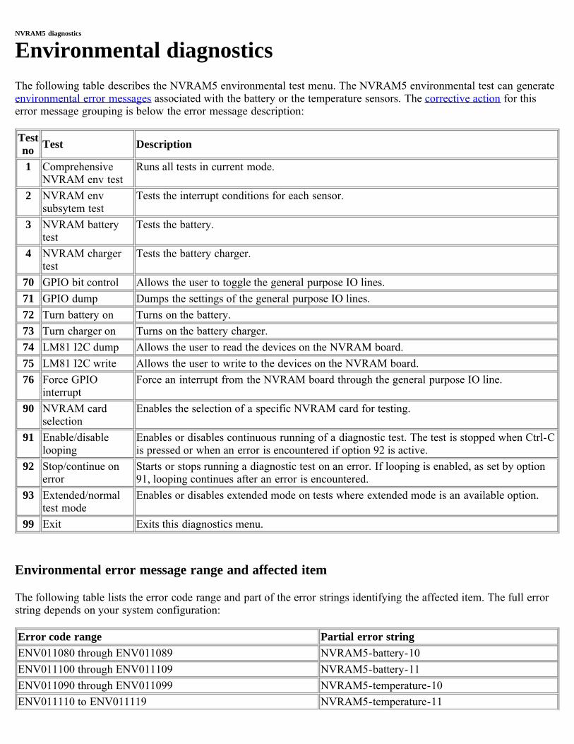
NVRAM5 diagnostics
Environmental diagnosticsThe following table describes the NVRAM5 environmental test menu. The NVRAM5 environmental test can generateenvironmental error messages associated with the battery or the temperature sensors. The corrective action for thiserror message grouping is below the error message description:
Testno Test Description
1 ComprehensiveNVRAM env test
Runs all tests in current mode.
2 NVRAM envsubsytem test
Tests the interrupt conditions for each sensor.
3 NVRAM batterytest
Tests the battery.
4 NVRAM chargertest
Tests the battery charger.
70 GPIO bit control Allows the user to toggle the general purpose IO lines.71 GPIO dump Dumps the settings of the general purpose IO lines.72 Turn battery on Turns on the battery.73 Turn charger on Turns on the battery charger.74 LM81 I2C dump Allows the user to read the devices on the NVRAM board.75 LM81 I2C write Allows the user to write to the devices on the NVRAM board.76 Force GPIO
interruptForce an interrupt from the NVRAM board through the general purpose IO line.
90 NVRAM cardselection
Enables the selection of a specific NVRAM card for testing.
91 Enable/disablelooping
Enables or disables continuous running of a diagnostic test. The test is stopped when Ctrl-Cis pressed or when an error is encountered if option 92 is active.
92 Stop/continue onerror
Starts or stops running a diagnostic test on an error. If looping is enabled, as set by option91, looping continues after an error is encountered.
93 Extended/normaltest mode
Enables or disables extended mode on tests where extended mode is an available option.
99 Exit Exits this diagnostics menu.
Environmental error message range and affected item
The following table lists the error code range and part of the error strings identifying the affected item. The full errorstring depends on your system configuration:
Error code range Partial error stringENV011080 through ENV011089 NVRAM5-battery-10ENV011100 through ENV011109 NVRAM5-battery-11ENV011090 through ENV011099 NVRAM5-temperature-10ENV011110 to ENV011119 NVRAM5-temperature-11
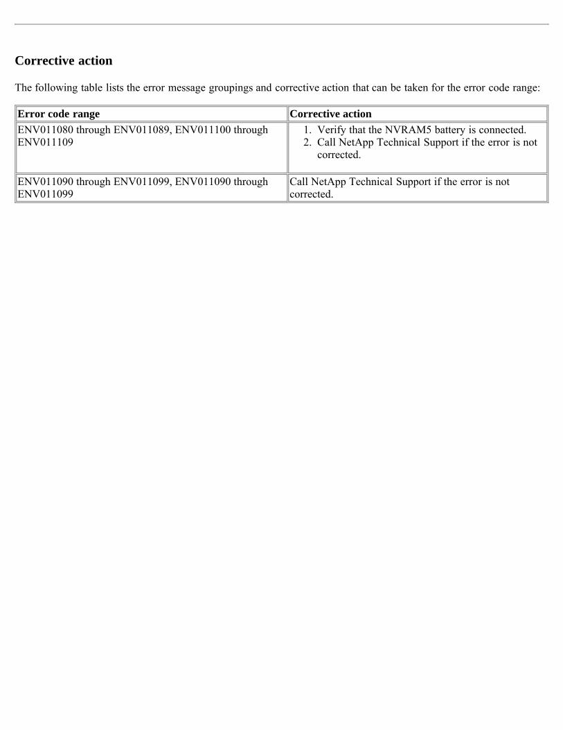
Corrective action
The following table lists the error message groupings and corrective action that can be taken for the error code range:
Error code range Corrective actionENV011080 through ENV011089, ENV011100 throughENV011109
1. Verify that the NVRAM5 battery is connected.2. Call NetApp Technical Support if the error is not
corrected.
ENV011090 through ENV011099, ENV011090 throughENV011099
Call NetApp Technical Support if the error is notcorrected.
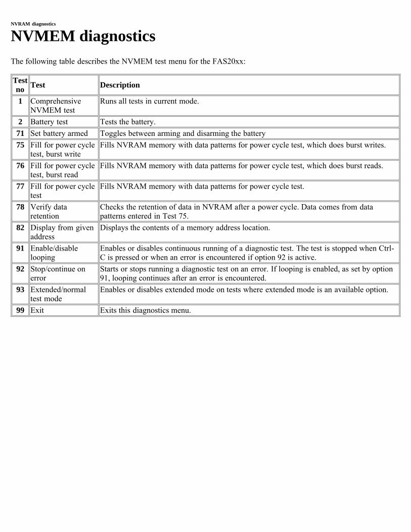
NVRAM diagnostics
NVMEM diagnosticsThe following table describes the NVMEM test menu for the FAS20xx:
Testno Test Description
1 ComprehensiveNVMEM test
Runs all tests in current mode.
2 Battery test Tests the battery.71 Set battery armed Toggles between arming and disarming the battery75 Fill for power cycle
test, burst writeFills NVRAM memory with data patterns for power cycle test, which does burst writes.
76 Fill for power cycletest, burst read
Fills NVRAM memory with data patterns for power cycle test, which does burst reads.
77 Fill for power cycletest
Fills NVRAM memory with data patterns for power cycle test.
78 Verify dataretention
Checks the retention of data in NVRAM after a power cycle. Data comes from datapatterns entered in Test 75.
82 Display from givenaddress
Displays the contents of a memory address location.
91 Enable/disablelooping
Enables or disables continuous running of a diagnostic test. The test is stopped when Ctrl-C is pressed or when an error is encountered if option 92 is active.
92 Stop/continue onerror
Starts or stops running a diagnostic test on an error. If looping is enabled, as set by option91, looping continues after an error is encountered.
93 Extended/normaltest mode
Enables or disables extended mode on tests where extended mode is an available option.
99 Exit Exits this diagnostics menu.
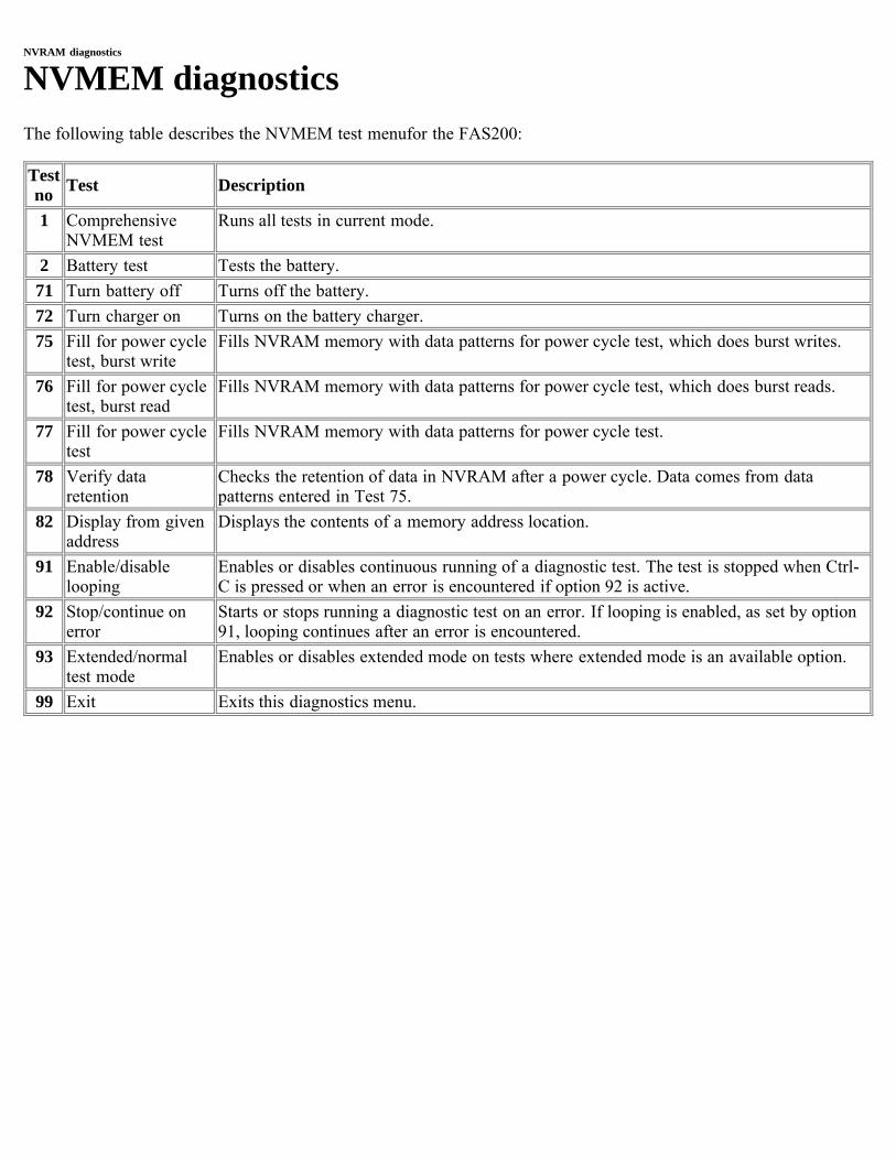
NVRAM diagnostics
NVMEM diagnosticsThe following table describes the NVMEM test menufor the FAS200:
Testno Test Description
1 ComprehensiveNVMEM test
Runs all tests in current mode.
2 Battery test Tests the battery.71 Turn battery off Turns off the battery.72 Turn charger on Turns on the battery charger.75 Fill for power cycle
test, burst writeFills NVRAM memory with data patterns for power cycle test, which does burst writes.
76 Fill for power cycletest, burst read
Fills NVRAM memory with data patterns for power cycle test, which does burst reads.
77 Fill for power cycletest
Fills NVRAM memory with data patterns for power cycle test.
78 Verify dataretention
Checks the retention of data in NVRAM after a power cycle. Data comes from datapatterns entered in Test 75.
82 Display from givenaddress
Displays the contents of a memory address location.
91 Enable/disablelooping
Enables or disables continuous running of a diagnostic test. The test is stopped when Ctrl-C is pressed or when an error is encountered if option 92 is active.
92 Stop/continue onerror
Starts or stops running a diagnostic test on an error. If looping is enabled, as set by option91, looping continues after an error is encountered.
93 Extended/normaltest mode
Enables or disables extended mode on tests where extended mode is an available option.
99 Exit Exits this diagnostics menu.
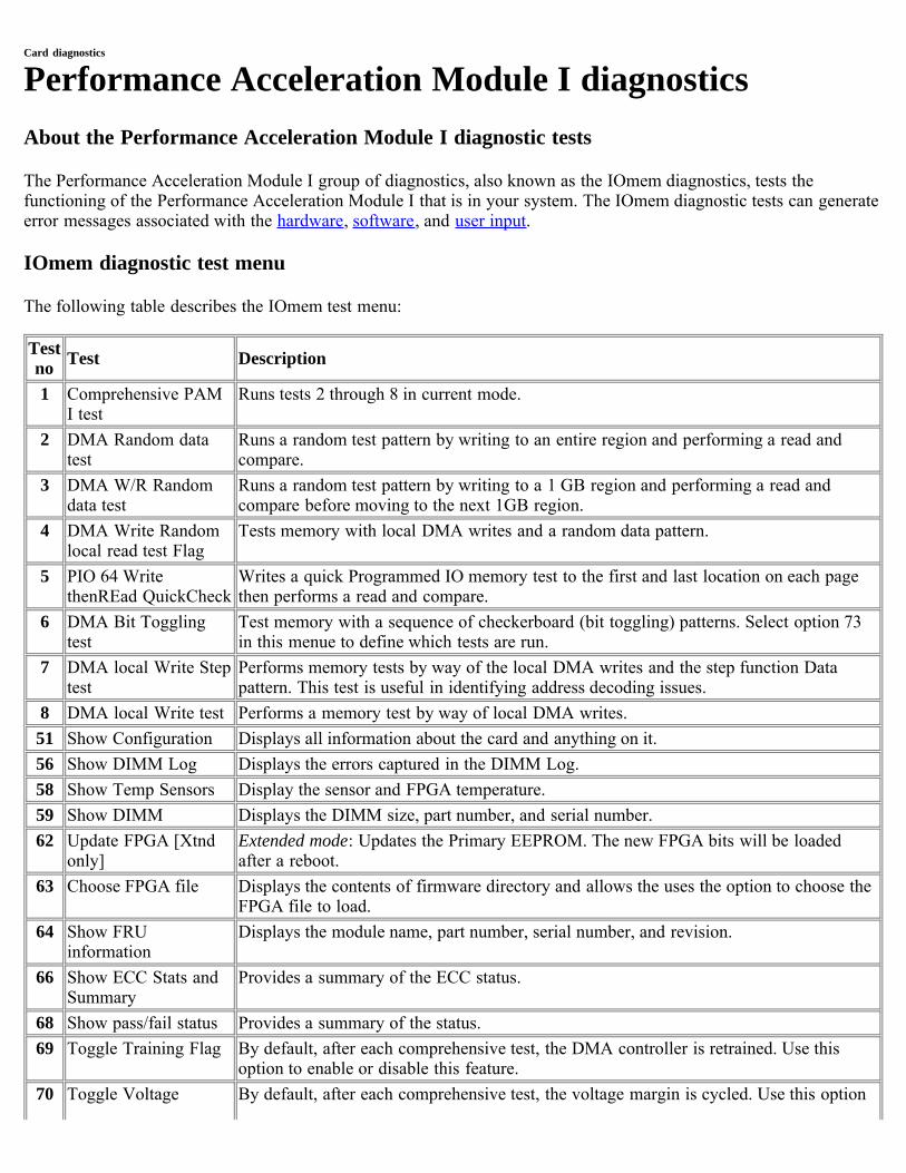
Card diagnostics
Performance Acceleration Module I diagnosticsAbout the Performance Acceleration Module I diagnostic tests
The Performance Acceleration Module I group of diagnostics, also known as the IOmem diagnostics, tests thefunctioning of the Performance Acceleration Module I that is in your system. The IOmem diagnostic tests can generateerror messages associated with the hardware, software, and user input.
IOmem diagnostic test menu
The following table describes the IOmem test menu:
Testno Test Description
1 Comprehensive PAMI test
Runs tests 2 through 8 in current mode.
2 DMA Random datatest
Runs a random test pattern by writing to an entire region and performing a read andcompare.
3 DMA W/R Randomdata test
Runs a random test pattern by writing to a 1 GB region and performing a read andcompare before moving to the next 1GB region.
4 DMA Write Randomlocal read test Flag
Tests memory with local DMA writes and a random data pattern.
5 PIO 64 WritethenREad QuickCheck
Writes a quick Programmed IO memory test to the first and last location on each pagethen performs a read and compare.
6 DMA Bit Togglingtest
Test memory with a sequence of checkerboard (bit toggling) patterns. Select option 73in this menue to define which tests are run.
7 DMA local Write Steptest
Performs memory tests by way of the local DMA writes and the step function Datapattern. This test is useful in identifying address decoding issues.
8 DMA local Write test Performs a memory test by way of local DMA writes.51 Show Configuration Displays all information about the card and anything on it.56 Show DIMM Log Displays the errors captured in the DIMM Log.58 Show Temp Sensors Display the sensor and FPGA temperature.59 Show DIMM Displays the DIMM size, part number, and serial number.62 Update FPGA [Xtnd
only]Extended mode: Updates the Primary EEPROM. The new FPGA bits will be loadedafter a reboot.
63 Choose FPGA file Displays the contents of firmware directory and allows the uses the option to choose theFPGA file to load.
64 Show FRUinformation
Displays the module name, part number, serial number, and revision.
66 Show ECC Stats andSummary
Provides a summary of the ECC status.
68 Show pass/fail status Provides a summary of the status.69 Toggle Training Flag By default, after each comprehensive test, the DMA controller is retrained. Use this
option to enable or disable this feature.70 Toggle Voltage By default, after each comprehensive test, the voltage margin is cycled. Use this option
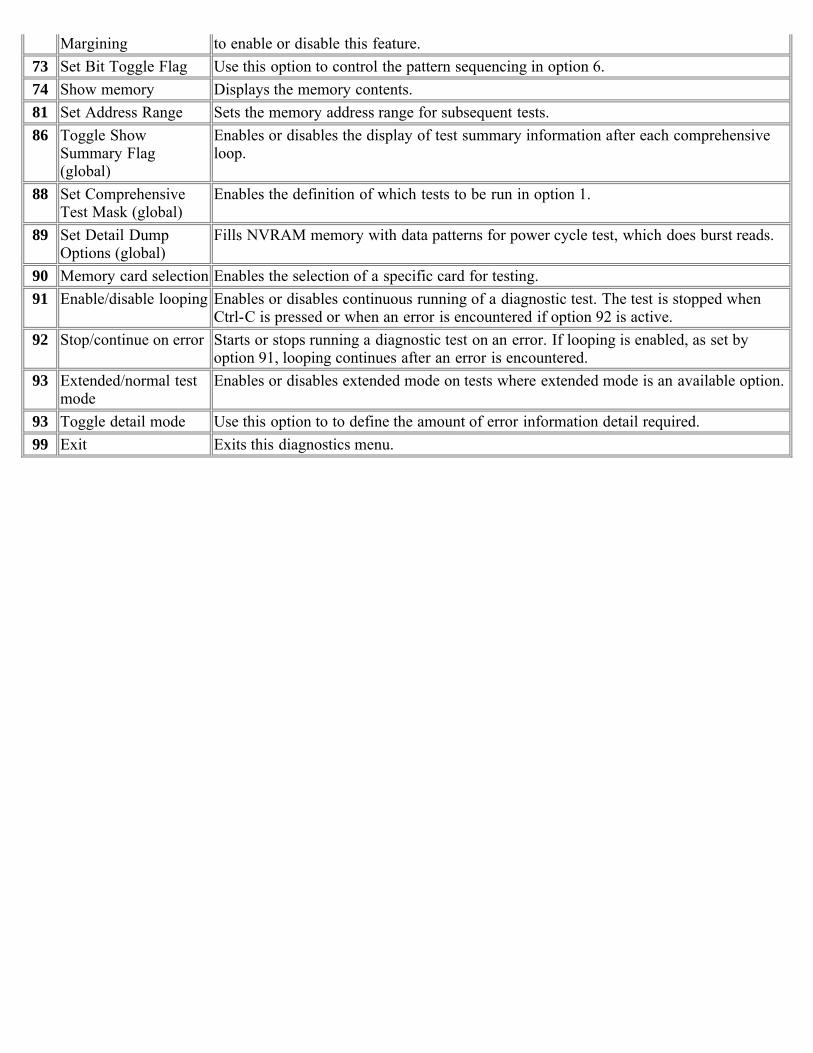
Margining to enable or disable this feature.73 Set Bit Toggle Flag Use this option to control the pattern sequencing in option 6.74 Show memory Displays the memory contents.81 Set Address Range Sets the memory address range for subsequent tests.86 Toggle Show
Summary Flag(global)
Enables or disables the display of test summary information after each comprehensiveloop.
88 Set ComprehensiveTest Mask (global)
Enables the definition of which tests to be run in option 1.
89 Set Detail DumpOptions (global)
Fills NVRAM memory with data patterns for power cycle test, which does burst reads.
90 Memory card selection Enables the selection of a specific card for testing.91 Enable/disable looping Enables or disables continuous running of a diagnostic test. The test is stopped when
Ctrl-C is pressed or when an error is encountered if option 92 is active.92 Stop/continue on error Starts or stops running a diagnostic test on an error. If looping is enabled, as set by
option 91, looping continues after an error is encountered.93 Extended/normal test
modeEnables or disables extended mode on tests where extended mode is an available option.
93 Toggle detail mode Use this option to to define the amount of error information detail required.99 Exit Exits this diagnostics menu.
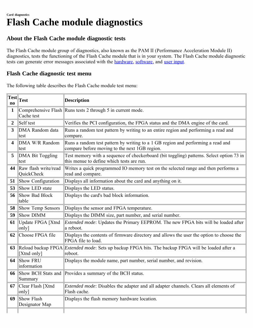
Card diagnostics
Flash Cache module diagnosticsAbout the Flash Cache module diagnostic tests
The Flash Cache module group of diagnostics, also known as the PAM II (Performance Acceleration Module II)diagnostics, tests the functioning of the Flash Cache module that is in your system. The Flash Cache module diagnostictests can generate error messages associated with the hardware, software, and user input.
Flash Cache diagnostic test menu
The following table describes the Flash Cache module test menu:
Testno Test Description
1 Comprehensive FlashCache test
Runs tests 2 through 5 in current mode.
2 Self test Verifies the PCI configuration, the FPGA status and the DMA engine of the card.3 DMA Random data
testRuns a random test pattern by writing to an entire region and performing a read andcompare.
4 DMA W/R Randomtest
Runs a random test pattern by writing to a 1 GB region and performing a read andcompare before moving to the next 1GB region.
5 DMA Bit Togglingtest
Test memory with a sequence of checkerboard (bit toggling) patterns. Select option 73 inthis menue to define which tests are run.
44 Raw flash write/readQuickCheck
Writes a quick programmed IO memory test on the selected range and then performs aread and compare.
51 Show Configuration Displays all information about the card and anything on it.53 Show LED state Displays the LED status.56 Show Bad Block
tableDisplays the card's bad block information.
58 Show Temp Sensors Displays the sensor and FPGA temperature.59 Show DIMM Displays the DIMM size, part number, and serial number.61 Update FPGA [Xtnd
only]Extended mode: Updates the Primary EEPROM. The new FPGA bits will be loaded aftera reboot.
62 Choose FPGA file Displays the contents of firmware directory and allows the user the option to choose theFPGA file to load.
63 Reload backup FPGA[Xtnd only]
Extended mode: Sets up backup FPGA bits. The backup FPGA will be loaded after areboot.
64 Show FRUinformation
Displays the module name, part number, serial number, and revision.
66 Show BCH Stats andSummary
Provides a summary of the BCH status.
67 Clear Flash [Xtndonly]
Extended mode: Disables the adapter and all adapter channels. Clears all elements ofFlash cache.
69 Show FlashDesignator Map
Displays the flash memory hardware location.
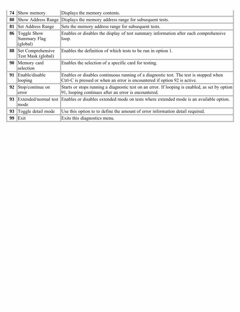
74 Show memory Displays the memory contents.80 Show Address Range Displays the memory address range for subsequent tests.81 Set Address Range Sets the memory address range for subsequent tests.86 Toggle Show
Summary Flag(global)
Enables or disables the display of test summary information after each comprehensiveloop.
88 Set ComprehensiveTest Mask (global)
Enables the definition of which tests to be run in option 1.
90 Memory cardselection
Enables the selection of a specific card for testing.
91 Enable/disablelooping
Enables or disables continuous running of a diagnostic test. The test is stopped whenCtrl-C is pressed or when an error is encountered if option 92 is active.
92 Stop/continue onerror
Starts or stops running a diagnostic test on an error. If looping is enabled, as set by option91, looping continues after an error is encountered.
93 Extended/normal testmode
Enables or disables extended mode on tests where extended mode is an available option.
93 Toggle detail mode Use this option to to define the amount of error information detail required.99 Exit Exits this diagnostics menu.
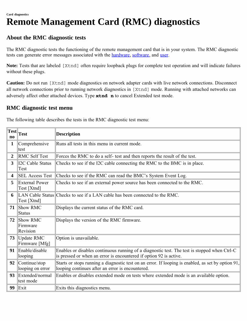
Card diagnostics
Remote Management Card (RMC) diagnosticsAbout the RMC diagnostic tests
The RMC diagnostic tests the functioning of the remote management card that is in your system. The RMC diagnostictests can generate error messages associated with the hardware, software, and user.
Note: Tests that are labeled [Xtnd] often require loopback plugs for complete test operation and will indicate failureswithout these plugs.
Caution: Do not run [Xtnd] mode diagnostics on network adapter cards with live network connections. Disconnectall network connections prior to running network diagnostics in [Xtnd] mode. Running with attached networks canadversely affect other attached devices. Type xtnd n to cancel Extended test mode.
RMC diagnostic test menu
The following table describes the tests in the RMC diagnostic test menu:
Testno Test Description
1 Comprehensivetest
Runs all tests in this menu in current mode.
2 RMC Self Test Forces the RMC to do a self- test and then reports the result of the test.3 I2C Cable Status
TestChecks to see if the I2C cable connecting the RMC to the BMC is in place.
4 SEL Access Test Checks to see if the RMC can read the BMC’s System Event Log.5 External Power
Test [Xtnd]Checks to see if an external power source has been connected to the RMC.
6 LAN Cable StatusTest [Xtnd]
Checks to see if a LAN cable has been connected to the RMC.
71 Show RMCStatus
Displays the current status of the RMC card.
72 Show RMCFirmwareRevision
Displays the version of the RMC firmware.
73 Update RMCFirmware [Mfg]
Option is unavailable.
91 Enable/disablelooping
Enables or disables continuous running of a diagnostic test. The test is stopped when Ctrl-Cis pressed or when an error is encountered if option 92 is active.
92 Continue/stoplooping on error
Starts or stops running a diagnostic test on an error. If looping is enabled, as set by option 91,looping continues after an error is encountered.
93 Extended/normaltest mode
Enables or disables extended mode on tests where extended mode is an available option.
99 Exit Exits this diagnostics menu.
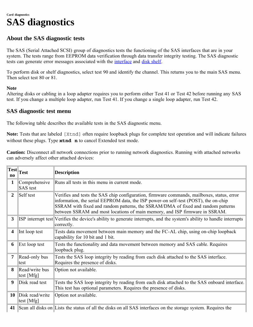
Card diagnostics
SAS diagnosticsAbout the SAS diagnostic tests
The SAS (Serial Attached SCSI) group of diagnostics tests the functioning of the SAS interfaces that are in yoursystem. The tests range from EEPROM data verification through data transfer integrity testing. The SAS diagnostictests can generate error messages associated with the interface and disk shelf.
To perform disk or shelf diagnostics, select test 90 and identify the channel. This returns you to the main SAS menu.Then select test 80 or 81.
NoteAltering disks or cabling in a loop adapter requires you to perform either Test 41 or Test 42 before running any SAStest. If you change a multiple loop adapter, run Test 41. If you change a single loop adapter, run Test 42.
SAS diagnostic test menu
The following table describes the available tests in the SAS diagnostic menu.
Note: Tests that are labeled [Xtnd] often require loopback plugs for complete test operation and will indicate failureswithout these plugs. Type xtnd n to cancel Extended test mode.
Caution: Disconnect all network connections prior to running network diagnostics. Running with attached networkscan adversely affect other attached devices:
Testno Test Description
1 ComprehensiveSAS test
Runs all tests in this menu in current mode.
2 Self test Verifies and tests the SAS chip configuration, firmware commands, mailboxes, status, errorinformation, the serial EEPROM data, the ISP power-on self-test (POST), the on-chipSSRAM with fixed and random patterns, the SSRAM/DMA of fixed and random patternsbetween SSRAM and most locations of main memory, and ISP firmware in SSRAM.
3 ISP interrupt test Verifies the device's ability to generate interrupts, and the system's ability to handle interruptscorrectly.
4 Int loop test Tests data movement between main memory and the FC-AL chip, using on-chip loopbackcapability for 10 bit and 1 bit.
6 Ext loop test Tests the functionality and data movement between memory and SAS cable. Requiresloopback plug.
7 Read-only bustest
Tests the SAS loop integrity by reading from each disk attached to the SAS interface.Requires the presence of disks.
8 Read/write bustest [Mfg]
Option not available.
9 Disk read test Tests the SAS loop integrity by reading from each disk attached to the SAS onboard interface.This test has optional parameters. Requires the presence of disks.
10 Disk read/writetest [Mfg]
Option not available.
41 Scan all disks on Lists the status of all the disks on all SAS interfaces on the storage system. Requires the
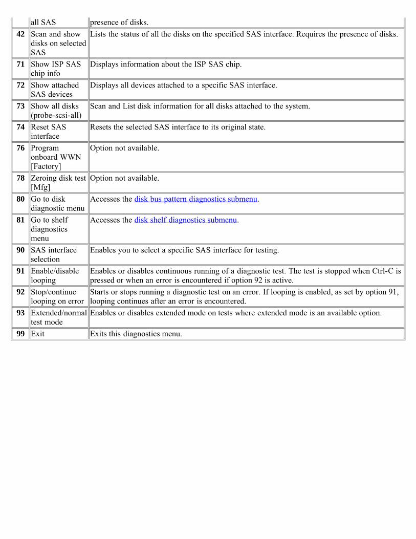
all SAS presence of disks.42 Scan and show
disks on selectedSAS
Lists the status of all the disks on the specified SAS interface. Requires the presence of disks.
71 Show ISP SASchip info
Displays information about the ISP SAS chip.
72 Show attachedSAS devices
Displays all devices attached to a specific SAS interface.
73 Show all disks(probe-scsi-all)
Scan and List disk information for all disks attached to the system.
74 Reset SASinterface
Resets the selected SAS interface to its original state.
76 Programonboard WWN[Factory]
Option not available.
78 Zeroing disk test[Mfg]
Option not available.
80 Go to diskdiagnostic menu
Accesses the disk bus pattern diagnostics submenu.
81 Go to shelfdiagnosticsmenu
Accesses the disk shelf diagnostics submenu.
90 SAS interfaceselection
Enables you to select a specific SAS interface for testing.
91 Enable/disablelooping
Enables or disables continuous running of a diagnostic test. The test is stopped when Ctrl-C ispressed or when an error is encountered if option 92 is active.
92 Stop/continuelooping on error
Starts or stops running a diagnostic test on an error. If looping is enabled, as set by option 91,looping continues after an error is encountered.
93 Extended/normaltest mode
Enables or disables extended mode on tests where extended mode is an available option.
99 Exit Exits this diagnostics menu.

[ Up ] [ Disk diagnostics ] [ Disk shelf diagnostics ]
Card diagnostics
Disk diagnostics submenuThe following table describes the FC-AL disk diagnostics submenu:
Testno Test Description
1 Perform drive selfdiagnostic test
The drive seeks a reserved non user-accessible cylinder and writes, reads, andverifies data for each data surface.
2 Low frequency pattern[Mfg]
Option not available.
3 Low transition densitypattern [Mfg]
4 Half-rate square pattern[Mfg]
5 Quarter-rate squarepattern [Mfg]
6 Contiguous '3' pattern[Mfg]
7 Composite pattern [Mfg]40 Read drive defect list Displays primary and grown defect list. This test has optional parameters. Requires
disks attached to the FC host adapter.99 Exit this menu Returns the user to the main FC-AL menu.
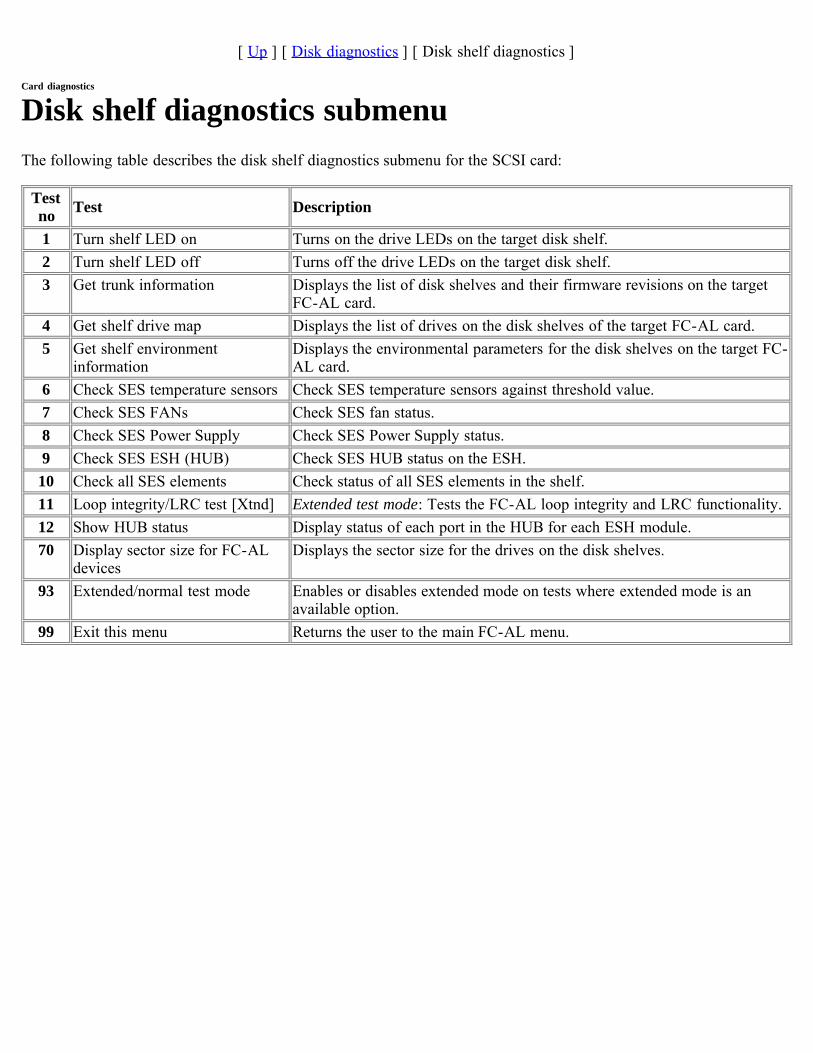
[ Up ] [ Disk diagnostics ] [ Disk shelf diagnostics ]
Card diagnostics
Disk shelf diagnostics submenuThe following table describes the disk shelf diagnostics submenu for the SCSI card:
Testno Test Description
1 Turn shelf LED on Turns on the drive LEDs on the target disk shelf.2 Turn shelf LED off Turns off the drive LEDs on the target disk shelf.3 Get trunk information Displays the list of disk shelves and their firmware revisions on the target
FC-AL card.4 Get shelf drive map Displays the list of drives on the disk shelves of the target FC-AL card.5 Get shelf environment
informationDisplays the environmental parameters for the disk shelves on the target FC-AL card.
6 Check SES temperature sensors Check SES temperature sensors against threshold value.7 Check SES FANs Check SES fan status.8 Check SES Power Supply Check SES Power Supply status.9 Check SES ESH (HUB) Check SES HUB status on the ESH.
10 Check all SES elements Check status of all SES elements in the shelf.11 Loop integrity/LRC test [Xtnd] Extended test mode: Tests the FC-AL loop integrity and LRC functionality.12 Show HUB status Display status of each port in the HUB for each ESH module.70 Display sector size for FC-AL
devicesDisplays the sector size for the drives on the disk shelves.
93 Extended/normal test mode Enables or disables extended mode on tests where extended mode is anavailable option.
99 Exit this menu Returns the user to the main FC-AL menu.
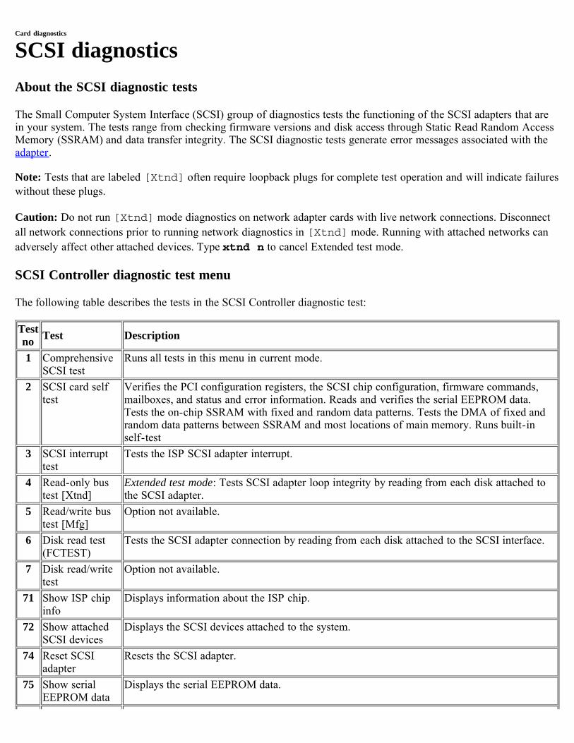
Card diagnostics
SCSI diagnosticsAbout the SCSI diagnostic tests
The Small Computer System Interface (SCSI) group of diagnostics tests the functioning of the SCSI adapters that arein your system. The tests range from checking firmware versions and disk access through Static Read Random AccessMemory (SSRAM) and data transfer integrity. The SCSI diagnostic tests generate error messages associated with theadapter.
Note: Tests that are labeled [Xtnd] often require loopback plugs for complete test operation and will indicate failureswithout these plugs.
Caution: Do not run [Xtnd] mode diagnostics on network adapter cards with live network connections. Disconnectall network connections prior to running network diagnostics in [Xtnd] mode. Running with attached networks canadversely affect other attached devices. Type xtnd n to cancel Extended test mode.
SCSI Controller diagnostic test menu
The following table describes the tests in the SCSI Controller diagnostic test:
Testno Test Description
1 ComprehensiveSCSI test
Runs all tests in this menu in current mode.
2 SCSI card selftest
Verifies the PCI configuration registers, the SCSI chip configuration, firmware commands,mailboxes, and status and error information. Reads and verifies the serial EEPROM data.Tests the on-chip SSRAM with fixed and random data patterns. Tests the DMA of fixed andrandom data patterns between SSRAM and most locations of main memory. Runs built-inself-test
3 SCSI interrupttest
Tests the ISP SCSI adapter interrupt.
4 Read-only bustest [Xtnd]
Extended test mode: Tests SCSI adapter loop integrity by reading from each disk attached tothe SCSI adapter.
5 Read/write bustest [Mfg]
Option not available.
6 Disk read test(FCTEST)
Tests the SCSI adapter connection by reading from each disk attached to the SCSI interface.
7 Disk read/writetest
Option not available.
71 Show ISP chipinfo
Displays information about the ISP chip.
72 Show attachedSCSI devices
Displays the SCSI devices attached to the system.
74 Reset SCSIadapter
Resets the SCSI adapter.
75 Show serialEEPROM data
Displays the serial EEPROM data.
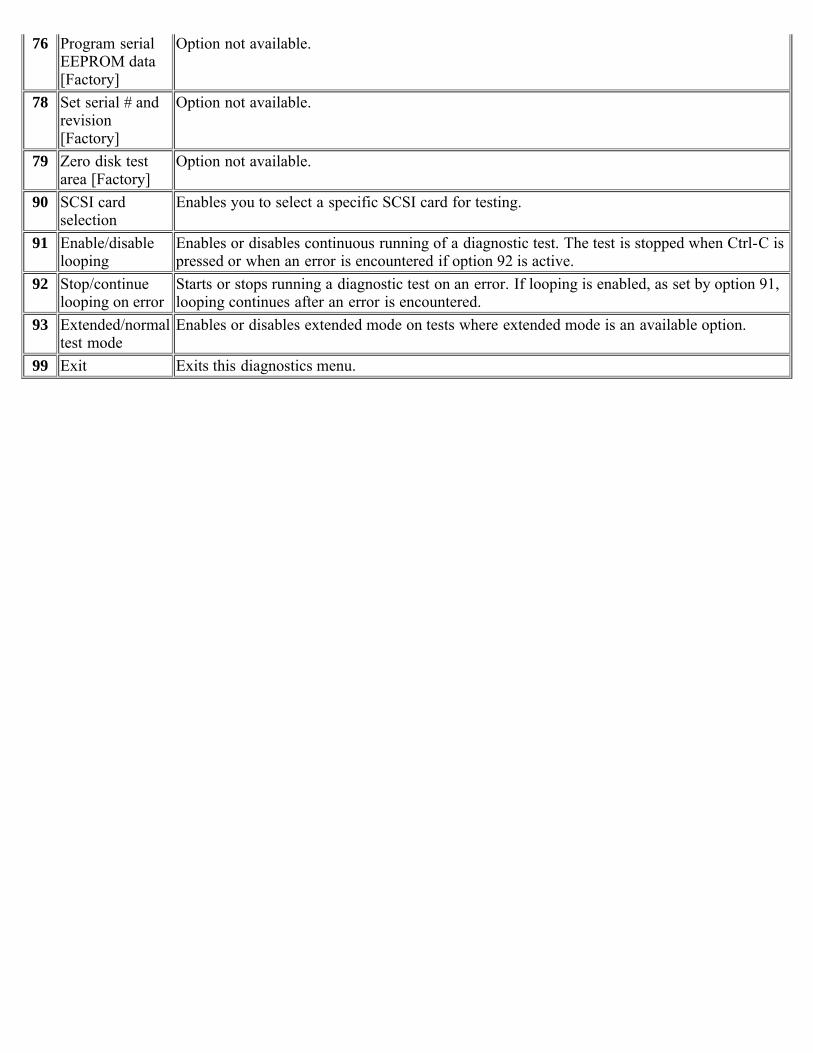
76 Program serialEEPROM data[Factory]
Option not available.
78 Set serial # andrevision[Factory]
Option not available.
79 Zero disk testarea [Factory]
Option not available.
90 SCSI cardselection
Enables you to select a specific SCSI card for testing.
91 Enable/disablelooping
Enables or disables continuous running of a diagnostic test. The test is stopped when Ctrl-C ispressed or when an error is encountered if option 92 is active.
92 Stop/continuelooping on error
Starts or stops running a diagnostic test on an error. If looping is enabled, as set by option 91,looping continues after an error is encountered.
93 Extended/normaltest mode
Enables or disables extended mode on tests where extended mode is an available option.
99 Exit Exits this diagnostics menu.
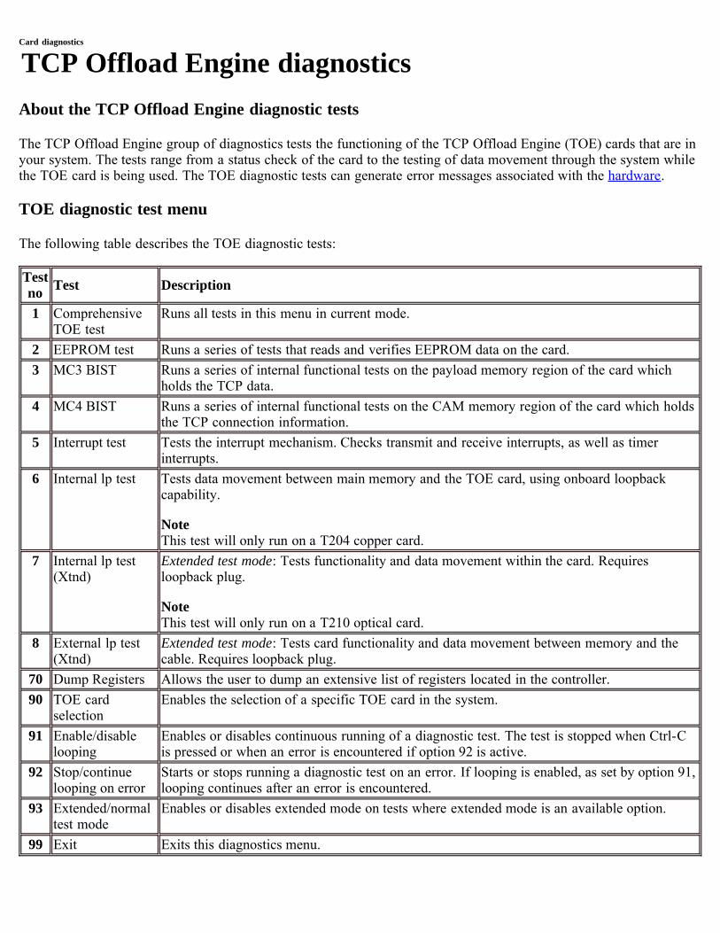
Card diagnostics
TCP Offload Engine diagnosticsAbout the TCP Offload Engine diagnostic tests
The TCP Offload Engine group of diagnostics tests the functioning of the TCP Offload Engine (TOE) cards that are inyour system. The tests range from a status check of the card to the testing of data movement through the system whilethe TOE card is being used. The TOE diagnostic tests can generate error messages associated with the hardware.
TOE diagnostic test menu
The following table describes the TOE diagnostic tests:
Testno Test Description
1 ComprehensiveTOE test
Runs all tests in this menu in current mode.
2 EEPROM test Runs a series of tests that reads and verifies EEPROM data on the card.3 MC3 BIST Runs a series of internal functional tests on the payload memory region of the card which
holds the TCP data.4 MC4 BIST Runs a series of internal functional tests on the CAM memory region of the card which holds
the TCP connection information.5 Interrupt test Tests the interrupt mechanism. Checks transmit and receive interrupts, as well as timer
interrupts.6 Internal lp test Tests data movement between main memory and the TOE card, using onboard loopback
capability.
NoteThis test will only run on a T204 copper card.
7 Internal lp test(Xtnd)
Extended test mode: Tests functionality and data movement within the card. Requiresloopback plug.
NoteThis test will only run on a T210 optical card.
8 External lp test(Xtnd)
Extended test mode: Tests card functionality and data movement between memory and thecable. Requires loopback plug.
70 Dump Registers Allows the user to dump an extensive list of registers located in the controller.90 TOE card
selectionEnables the selection of a specific TOE card in the system.
91 Enable/disablelooping
Enables or disables continuous running of a diagnostic test. The test is stopped when Ctrl-Cis pressed or when an error is encountered if option 92 is active.
92 Stop/continuelooping on error
Starts or stops running a diagnostic test on an error. If looping is enabled, as set by option 91,looping continues after an error is encountered.
93 Extended/normaltest mode
Enables or disables extended mode on tests where extended mode is an available option.
99 Exit Exits this diagnostics menu.
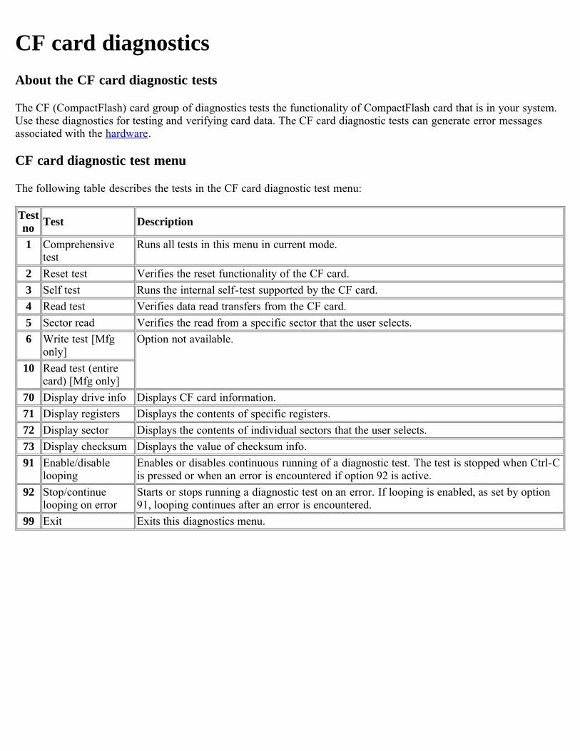
CF card diagnosticsAbout the CF card diagnostic tests
The CF (CompactFlash) card group of diagnostics tests the functionality of CompactFlash card that is in your system.Use these diagnostics for testing and verifying card data. The CF card diagnostic tests can generate error messagesassociated with the hardware.
CF card diagnostic test menu
The following table describes the tests in the CF card diagnostic test menu:
Testno Test Description
1 Comprehensivetest
Runs all tests in this menu in current mode.
2 Reset test Verifies the reset functionality of the CF card.3 Self test Runs the internal self-test supported by the CF card.4 Read test Verifies data read transfers from the CF card.5 Sector read Verifies the read from a specific sector that the user selects.6 Write test [Mfg
only]Option not available.
10 Read test (entirecard) [Mfg only]
70 Display drive info Displays CF card information.71 Display registers Displays the contents of specific registers.72 Display sector Displays the contents of individual sectors that the user selects.73 Display checksum Displays the value of checksum info.91 Enable/disable
loopingEnables or disables continuous running of a diagnostic test. The test is stopped when Ctrl-Cis pressed or when an error is encountered if option 92 is active.
92 Stop/continuelooping on error
Starts or stops running a diagnostic test on an error. If looping is enabled, as set by option91, looping continues after an error is encountered.
99 Exit Exits this diagnostics menu.
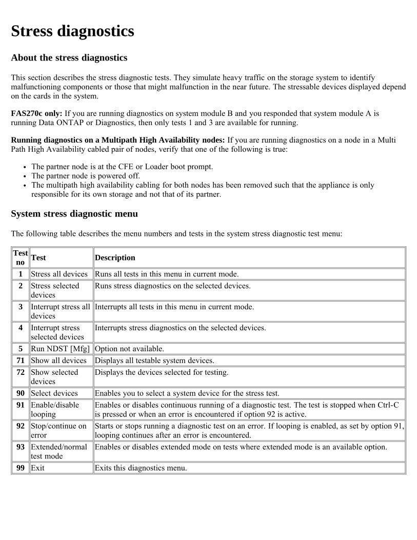
Stress diagnosticsAbout the stress diagnostics
This section describes the stress diagnostic tests. They simulate heavy traffic on the storage system to identifymalfunctioning components or those that might malfunction in the near future. The stressable devices displayed dependon the cards in the system.
FAS270c only: If you are running diagnostics on system module B and you responded that system module A isrunning Data ONTAP or Diagnostics, then only tests 1 and 3 are available for running.
Running diagnostics on a Multipath High Availability nodes: If you are running diagnostics on a node in a MultiPath High Availability cabled pair of nodes, verify that one of the following is true:
The partner node is at the CFE or Loader boot prompt.The partner node is powered off.The multipath high availability cabling for both nodes has been removed such that the appliance is onlyresponsible for its own storage and not that of its partner.
System stress diagnostic menu
The following table describes the menu numbers and tests in the system stress diagnostic test menu:
Testno Test Description
1 Stress all devices Runs all tests in this menu in current mode.2 Stress selected
devicesRuns stress diagnostics on the selected devices.
3 Interrupt stress alldevices
Interrupts all tests in this menu in current mode.
4 Interrupt stressselected devices
Interrupts stress diagnostics on the selected devices.
5 Run NDST [Mfg] Option not available.71 Show all devices Displays all testable system devices.72 Show selected
devicesDisplays the devices selected for testing.
90 Select devices Enables you to select a system device for the stress test.91 Enable/disable
loopingEnables or disables continuous running of a diagnostic test. The test is stopped when Ctrl-Cis pressed or when an error is encountered if option 92 is active.
92 Stop/continue onerror
Starts or stops running a diagnostic test on an error. If looping is enabled, as set by option 91,looping continues after an error is encountered.
93 Extended/normaltest mode
Enables or disables extended mode on tests where extended mode is an available option.
99 Exit Exits this diagnostics menu.
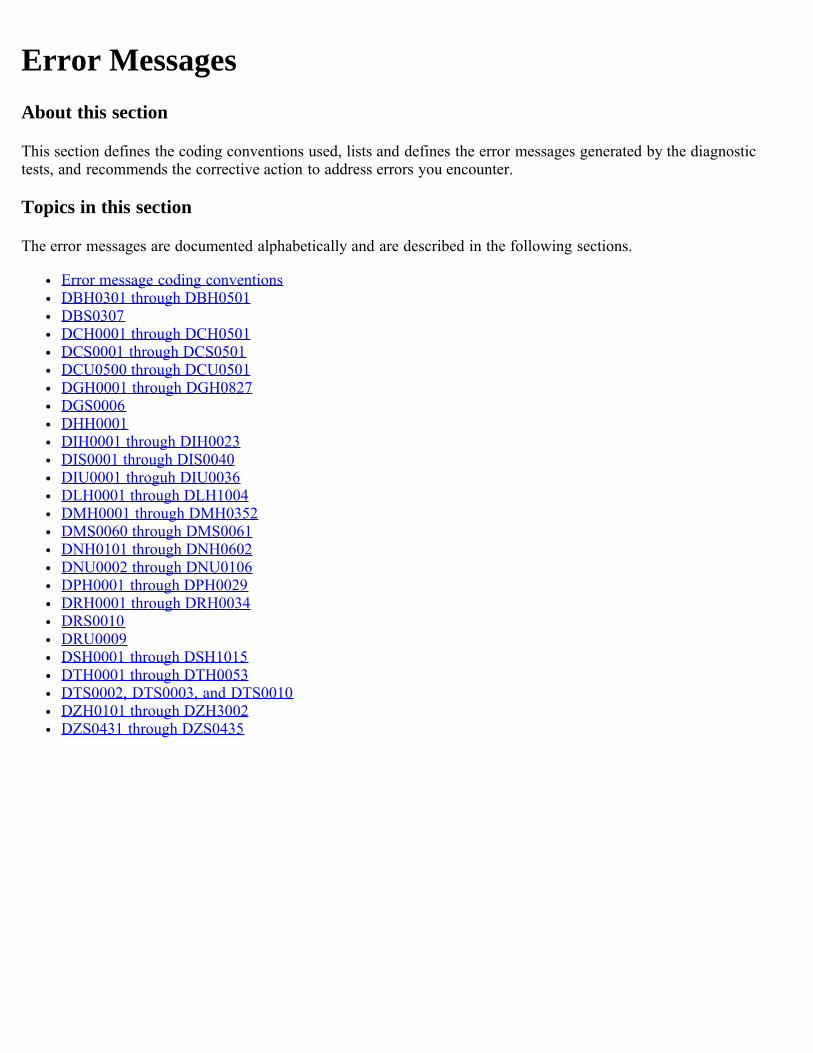
Error MessagesAbout this section
This section defines the coding conventions used, lists and defines the error messages generated by the diagnostictests, and recommends the corrective action to address errors you encounter.
Topics in this section
The error messages are documented alphabetically and are described in the following sections.
Error message coding conventionsDBH0301 through DBH0501DBS0307DCH0001 through DCH0501DCS0001 through DCS0501DCU0500 through DCU0501DGH0001 through DGH0827DGS0006DHH0001DIH0001 through DIH0023DIS0001 through DIS0040DIU0001 throguh DIU0036DLH0001 through DLH1004DMH0001 through DMH0352DMS0060 through DMS0061DNH0101 through DNH0602DNU0002 through DNU0106DPH0001 through DPH0029DRH0001 through DRH0034DRS0010DRU0009DSH0001 through DSH1015DTH0001 through DTH0053DTS0002, DTS0003, and DTS0010DZH0101 through DZH3002DZS0431 through DZS0435
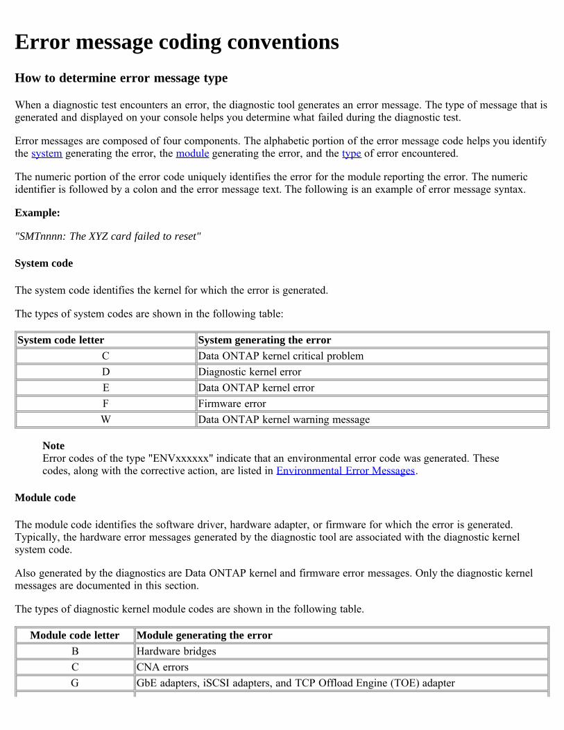
Error message coding conventionsHow to determine error message type
When a diagnostic test encounters an error, the diagnostic tool generates an error message. The type of message that isgenerated and displayed on your console helps you determine what failed during the diagnostic test.
Error messages are composed of four components. The alphabetic portion of the error message code helps you identifythe system generating the error, the module generating the error, and the type of error encountered.
The numeric portion of the error code uniquely identifies the error for the module reporting the error. The numericidentifier is followed by a colon and the error message text. The following is an example of error message syntax.
Example:
"SMTnnnn: The XYZ card failed to reset"
System code
The system code identifies the kernel for which the error is generated.
The types of system codes are shown in the following table:
System code letter System generating the errorC Data ONTAP kernel critical problemD Diagnostic kernel errorE Data ONTAP kernel errorF Firmware errorW Data ONTAP kernel warning message
NoteError codes of the type "ENVxxxxxx" indicate that an environmental error code was generated. Thesecodes, along with the corrective action, are listed in Environmental Error Messages.
Module code
The module code identifies the software driver, hardware adapter, or firmware for which the error is generated.Typically, the hardware error messages generated by the diagnostic tool are associated with the diagnostic kernelsystem code.
Also generated by the diagnostics are Data ONTAP kernel and firmware error messages. Only the diagnostic kernelmessages are documented in this section.
The types of diagnostic kernel module codes are shown in the following table.
Module code letter Module generating the errorB Hardware bridgesC CNA errorsG GbE adapters, iSCSI adapters, and TCP Offload Engine (TOE) adapter
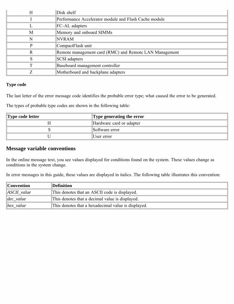
H Disk shelfI Performance Accelerator module and Flash Cache moduleL FC-AL adaptersM Memory and onboard SIMMsN NVRAMP CompactFlash unitR Remote management card (RMC) and Remote LAN ManagementS SCSI adaptersT Baseboard management controllerZ Motherboard and backplane adapters
Type code
The last letter of the error message code identifies the probable error type; what caused the error to be generated.
The types of probable type codes are shown in the following table:
Type code letter Type generating the errorH Hardware card or adapterS Software errorU User error
Message variable conventions
In the online message text, you see values displayed for conditions found on the system. These values change asconditions in the system change.
In error messages in this guide, these values are displayed in italics. The following table illustrates this convention:
Convention DefinitionASCII_value This denotes that an ASCII code is displayed.dec_value This denotes that a decimal value is displayed.hex_value This denotes that a hexadecimal value is displayed.
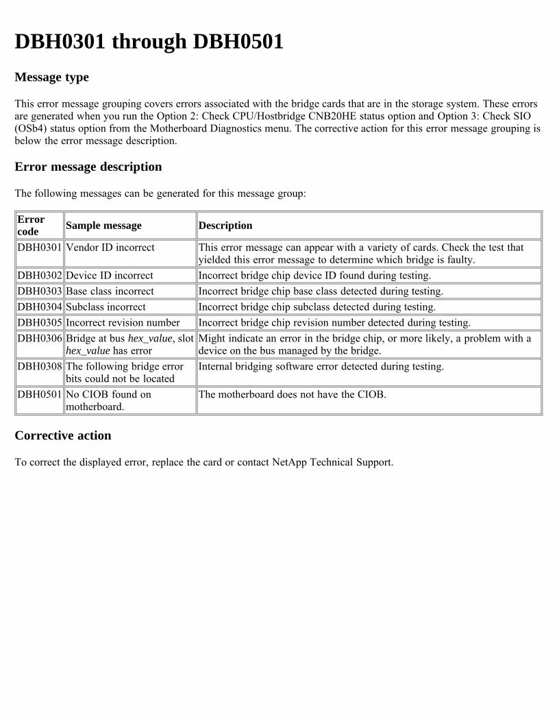
DBH0301 through DBH0501Message type
This error message grouping covers errors associated with the bridge cards that are in the storage system. These errorsare generated when you run the Option 2: Check CPU/Hostbridge CNB20HE status option and Option 3: Check SIO(OSb4) status option from the Motherboard Diagnostics menu. The corrective action for this error message grouping isbelow the error message description.
Error message description
The following messages can be generated for this message group:
Errorcode Sample message Description
DBH0301 Vendor ID incorrect This error message can appear with a variety of cards. Check the test thatyielded this error message to determine which bridge is faulty.
DBH0302 Device ID incorrect Incorrect bridge chip device ID found during testing.DBH0303 Base class incorrect Incorrect bridge chip base class detected during testing.DBH0304 Subclass incorrect Incorrect bridge chip subclass detected during testing.DBH0305 Incorrect revision number Incorrect bridge chip revision number detected during testing.DBH0306 Bridge at bus hex_value, slot
hex_value has errorMight indicate an error in the bridge chip, or more likely, a problem with adevice on the bus managed by the bridge.
DBH0308 The following bridge errorbits could not be located
Internal bridging software error detected during testing.
DBH0501 No CIOB found onmotherboard.
The motherboard does not have the CIOB.
Corrective action
To correct the displayed error, replace the card or contact NetApp Technical Support.
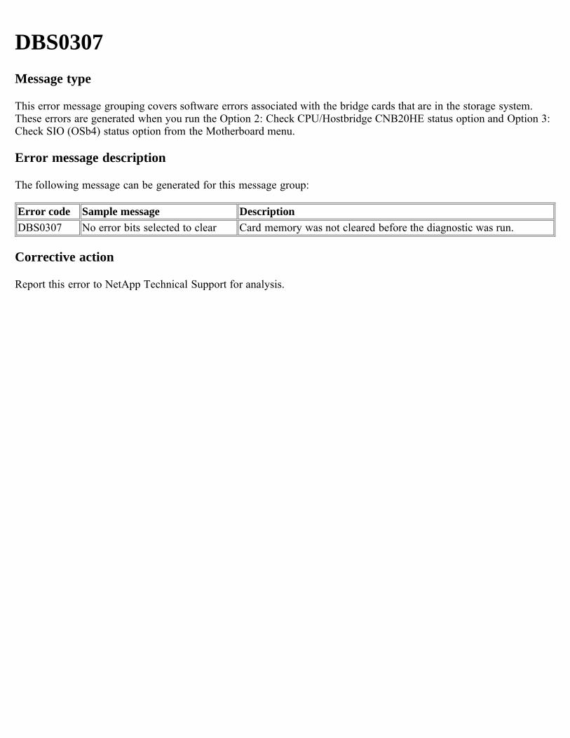
DBS0307Message type
This error message grouping covers software errors associated with the bridge cards that are in the storage system.These errors are generated when you run the Option 2: Check CPU/Hostbridge CNB20HE status option and Option 3:Check SIO (OSb4) status option from the Motherboard menu.
Error message description
The following message can be generated for this message group:
Error code Sample message DescriptionDBS0307 No error bits selected to clear Card memory was not cleared before the diagnostic was run.
Corrective action
Report this error to NetApp Technical Support for analysis.
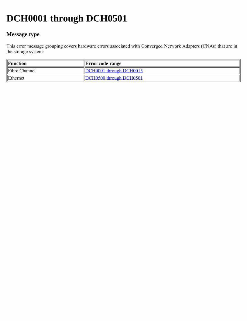
DCH0001 through DCH0501Message type
This error message grouping covers hardware errors associated with Converged Network Adapters (CNAs) that are inthe storage system:
Function Error code rangeFibre Channel DCH0001 through DCH0015Ethernet DCH0500 through DCH0501
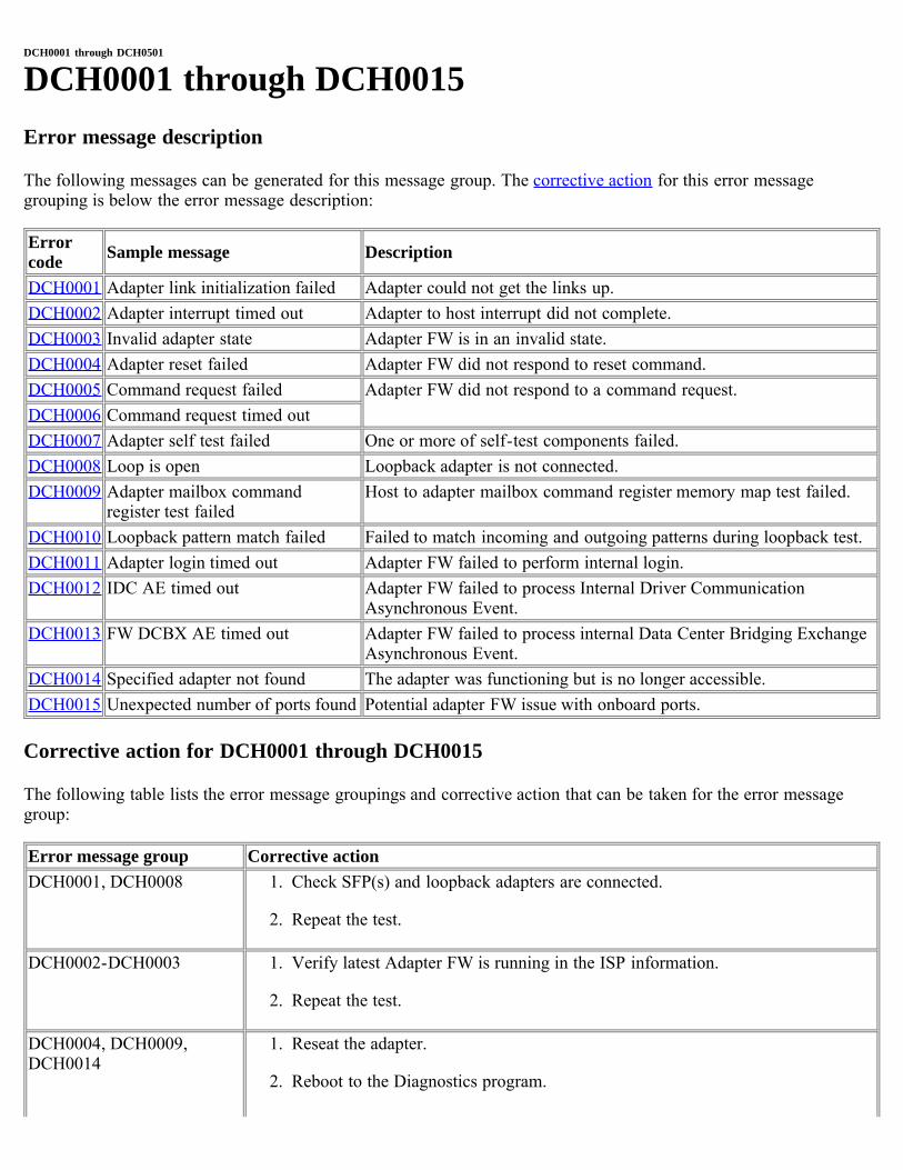
DCH0001 through DCH0501
DCH0001 through DCH0015Error message description
The following messages can be generated for this message group. The corrective action for this error messagegrouping is below the error message description:
Errorcode Sample message Description
DCH0001 Adapter link initialization failed Adapter could not get the links up.DCH0002 Adapter interrupt timed out Adapter to host interrupt did not complete.DCH0003 Invalid adapter state Adapter FW is in an invalid state.DCH0004 Adapter reset failed Adapter FW did not respond to reset command.DCH0005 Command request failed Adapter FW did not respond to a command request.DCH0006 Command request timed outDCH0007 Adapter self test failed One or more of self-test components failed.DCH0008 Loop is open Loopback adapter is not connected.DCH0009 Adapter mailbox command
register test failedHost to adapter mailbox command register memory map test failed.
DCH0010 Loopback pattern match failed Failed to match incoming and outgoing patterns during loopback test.DCH0011 Adapter login timed out Adapter FW failed to perform internal login.DCH0012 IDC AE timed out Adapter FW failed to process Internal Driver Communication
Asynchronous Event.DCH0013 FW DCBX AE timed out Adapter FW failed to process internal Data Center Bridging Exchange
Asynchronous Event.DCH0014 Specified adapter not found The adapter was functioning but is no longer accessible.DCH0015 Unexpected number of ports found Potential adapter FW issue with onboard ports.
Corrective action for DCH0001 through DCH0015
The following table lists the error message groupings and corrective action that can be taken for the error messagegroup:
Error message group Corrective actionDCH0001, DCH0008 1. Check SFP(s) and loopback adapters are connected.
2. Repeat the test.
DCH0002-DCH0003 1. Verify latest Adapter FW is running in the ISP information.
2. Repeat the test.
DCH0004, DCH0009,DCH0014
1. Reseat the adapter.
2. Reboot to the Diagnostics program.
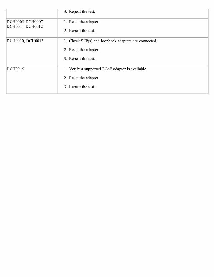
3. Repeat the test.
DCH0005-DCH0007DCH0011-DCH0012
1. Reset the adapter .
2. Repeat the test.
DCH0010, DCH0013 1. Check SFP(s) and loopback adapters are connected.
2. Reset the adapter.
3. Repeat the test.
DCH0015 1. Verify a supported FCoE adapter is available.
2. Reset the adapter.
3. Repeat the test.
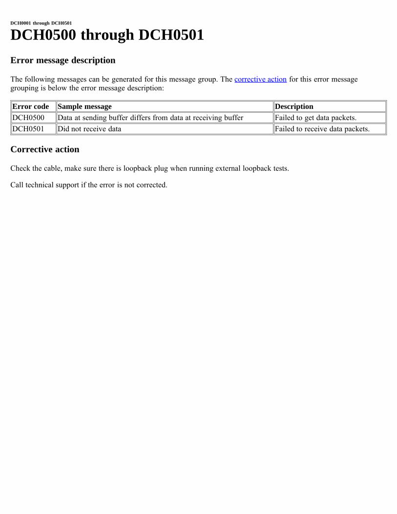
DCH0001 through DCH0501
DCH0500 through DCH0501Error message description
The following messages can be generated for this message group. The corrective action for this error messagegrouping is below the error message description:
Error code Sample message DescriptionDCH0500 Data at sending buffer differs from data at receiving buffer Failed to get data packets.DCH0501 Did not receive data Failed to receive data packets.
Corrective action
Check the cable, make sure there is loopback plug when running external loopback tests.
Call technical support if the error is not corrected.
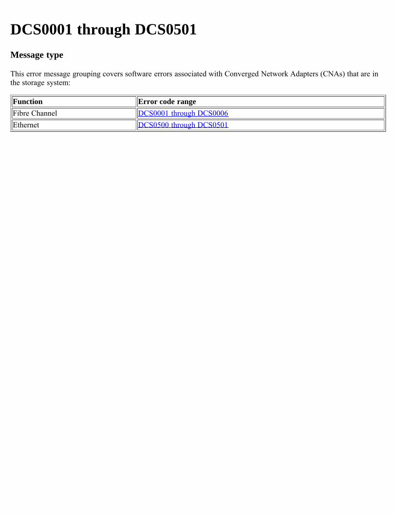
DCS0001 through DCS0501Message type
This error message grouping covers software errors associated with Converged Network Adapters (CNAs) that are inthe storage system:
Function Error code rangeFibre Channel DCS0001 through DCS0006Ethernet DCS0500 through DCS0501
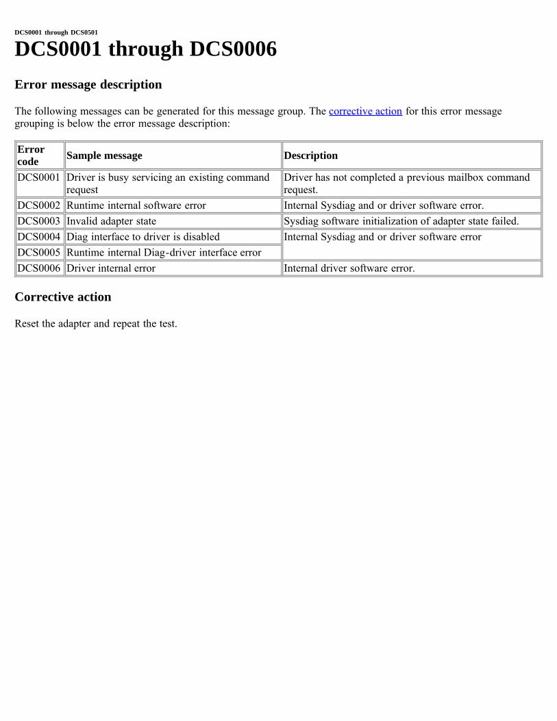
DCS0001 through DCS0501
DCS0001 through DCS0006Error message description
The following messages can be generated for this message group. The corrective action for this error messagegrouping is below the error message description:
Errorcode Sample message Description
DCS0001 Driver is busy servicing an existing commandrequest
Driver has not completed a previous mailbox commandrequest.
DCS0002 Runtime internal software error Internal Sysdiag and or driver software error.DCS0003 Invalid adapter state Sysdiag software initialization of adapter state failed.DCS0004 Diag interface to driver is disabled Internal Sysdiag and or driver software errorDCS0005 Runtime internal Diag-driver interface errorDCS0006 Driver internal error Internal driver software error.
Corrective action
Reset the adapter and repeat the test.
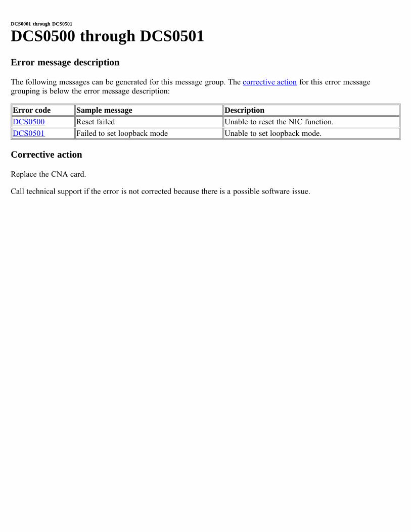
DCS0001 through DCS0501
DCS0500 through DCS0501Error message description
The following messages can be generated for this message group. The corrective action for this error messagegrouping is below the error message description:
Error code Sample message DescriptionDCS0500 Reset failed Unable to reset the NIC function.DCS0501 Failed to set loopback mode Unable to set loopback mode.
Corrective action
Replace the CNA card.
Call technical support if the error is not corrected because there is a possible software issue.
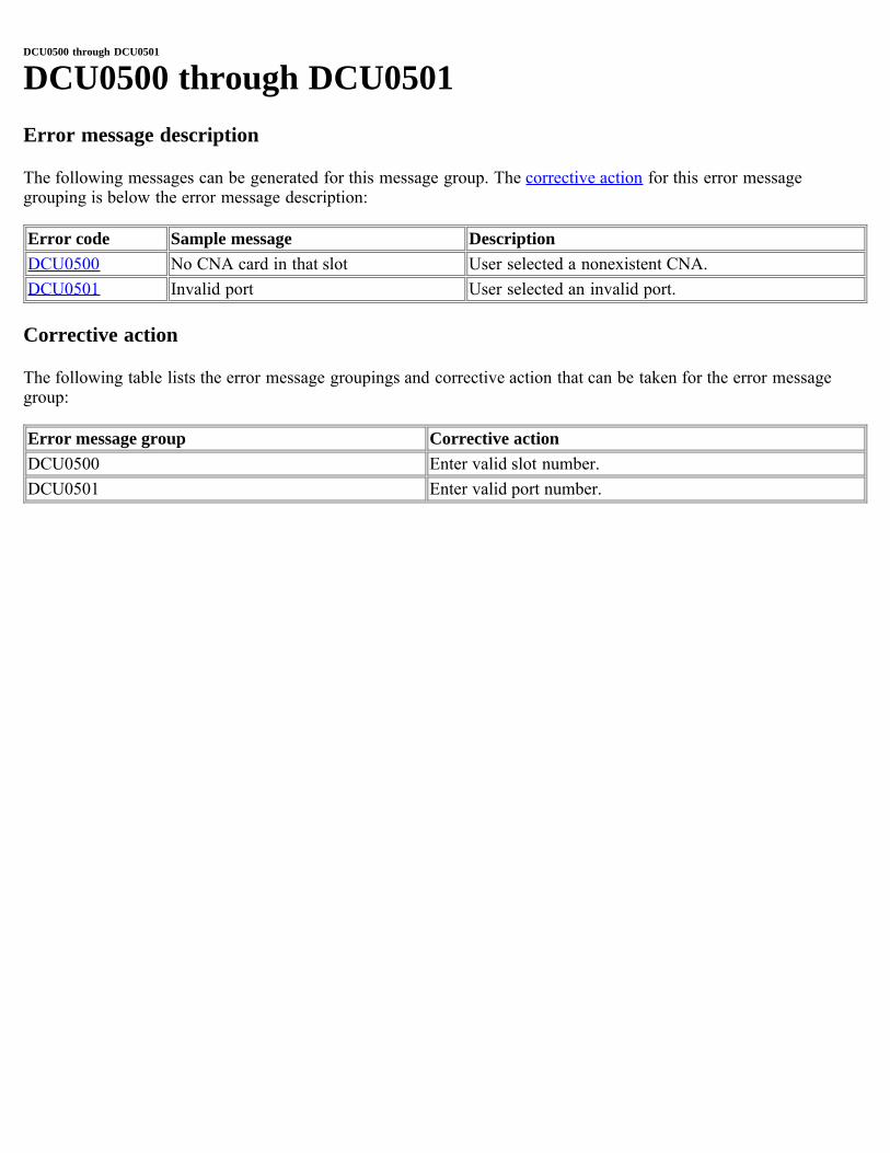
DCU0500 through DCU0501
DCU0500 through DCU0501Error message description
The following messages can be generated for this message group. The corrective action for this error messagegrouping is below the error message description:
Error code Sample message DescriptionDCU0500 No CNA card in that slot User selected a nonexistent CNA.DCU0501 Invalid port User selected an invalid port.
Corrective action
The following table lists the error message groupings and corrective action that can be taken for the error messagegroup:
Error message group Corrective actionDCU0500 Enter valid slot number.DCU0501 Enter valid port number.
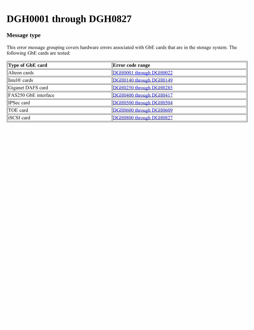
DGH0001 through DGH0827Message type
This error message grouping covers hardware errors associated with GbE cards that are in the storage system. Thefollowing GbE cards are tested:
Type of GbE card Error code rangeAlteon cards DGH0001 through DGH0022Intel® cards DGH0140 through DGH0149Giganet DAFS card DGH0250 through DGH0285FAS250 GbE interface DGH0400 through DGH0417IPSec card DGH0500 through DGH0504TOE card DGH0600 through DGH0609iSCSI card DGH0800 through DGH0827
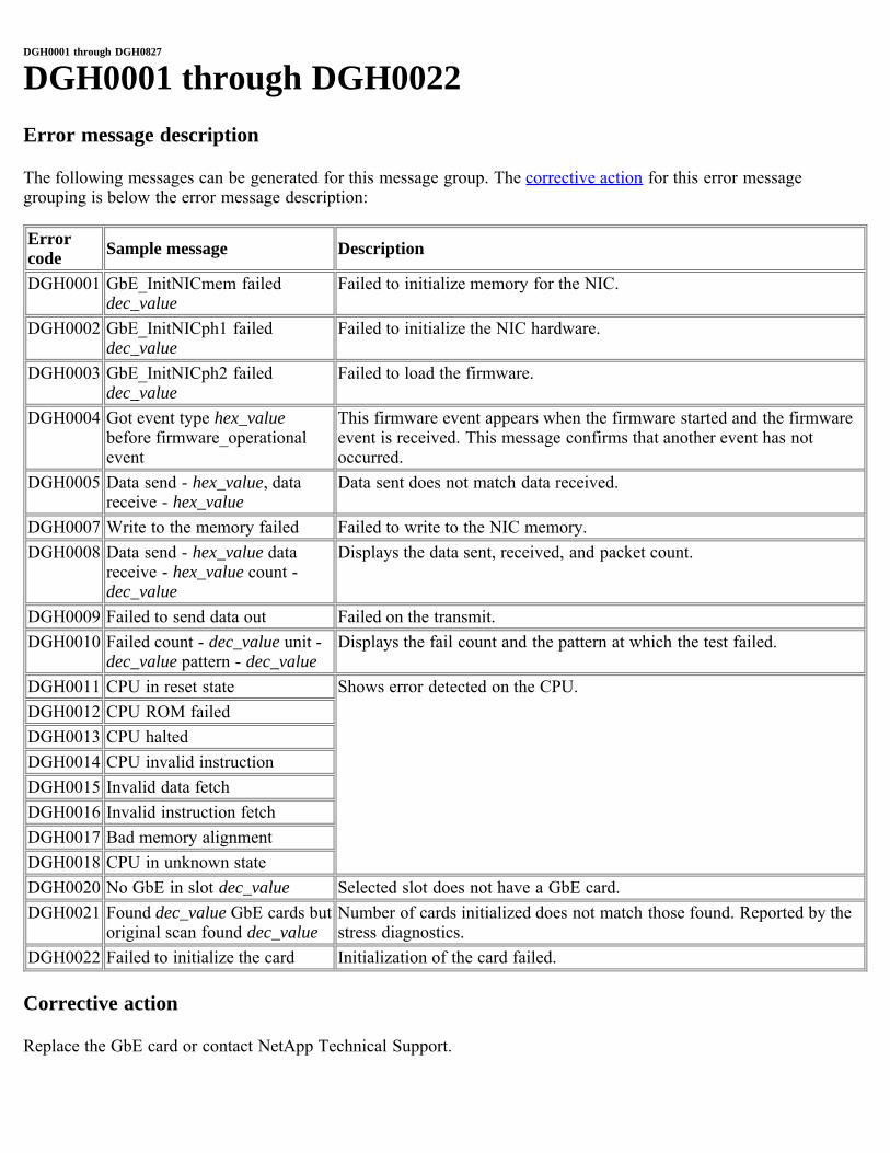
DGH0001 through DGH0827
DGH0001 through DGH0022Error message description
The following messages can be generated for this message group. The corrective action for this error messagegrouping is below the error message description:
Errorcode Sample message Description
DGH0001 GbE_InitNICmem faileddec_value
Failed to initialize memory for the NIC.
DGH0002 GbE_InitNICph1 faileddec_value
Failed to initialize the NIC hardware.
DGH0003 GbE_InitNICph2 faileddec_value
Failed to load the firmware.
DGH0004 Got event type hex_valuebefore firmware_operationalevent
This firmware event appears when the firmware started and the firmwareevent is received. This message confirms that another event has notoccurred.
DGH0005 Data send - hex_value, datareceive - hex_value
Data sent does not match data received.
DGH0007 Write to the memory failed Failed to write to the NIC memory.DGH0008 Data send - hex_value data
receive - hex_value count -dec_value
Displays the data sent, received, and packet count.
DGH0009 Failed to send data out Failed on the transmit.DGH0010 Failed count - dec_value unit -
dec_value pattern - dec_valueDisplays the fail count and the pattern at which the test failed.
DGH0011 CPU in reset state Shows error detected on the CPU.DGH0012 CPU ROM failedDGH0013 CPU haltedDGH0014 CPU invalid instructionDGH0015 Invalid data fetchDGH0016 Invalid instruction fetchDGH0017 Bad memory alignmentDGH0018 CPU in unknown stateDGH0020 No GbE in slot dec_value Selected slot does not have a GbE card.DGH0021 Found dec_value GbE cards but
original scan found dec_valueNumber of cards initialized does not match those found. Reported by thestress diagnostics.
DGH0022 Failed to initialize the card Initialization of the card failed.
Corrective action
Replace the GbE card or contact NetApp Technical Support.
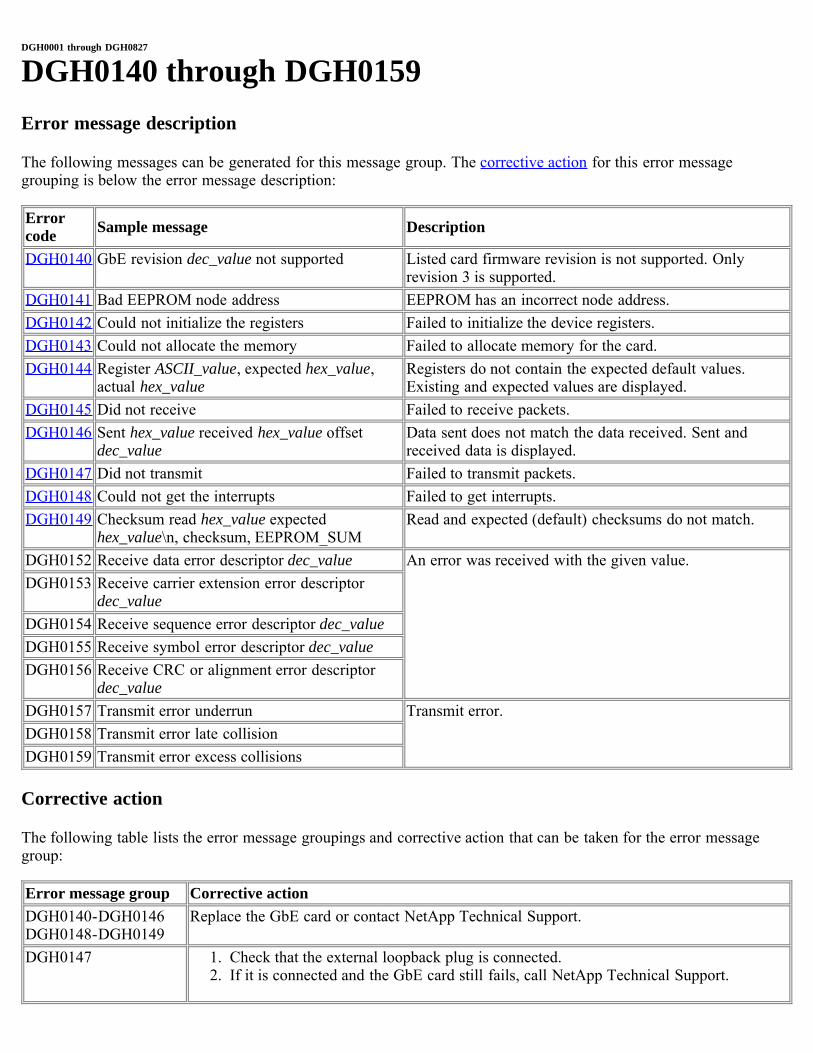
DGH0001 through DGH0827
DGH0140 through DGH0159Error message description
The following messages can be generated for this message group. The corrective action for this error messagegrouping is below the error message description:
Errorcode Sample message Description
DGH0140 GbE revision dec_value not supported Listed card firmware revision is not supported. Onlyrevision 3 is supported.
DGH0141 Bad EEPROM node address EEPROM has an incorrect node address.DGH0142 Could not initialize the registers Failed to initialize the device registers.DGH0143 Could not allocate the memory Failed to allocate memory for the card.DGH0144 Register ASCII_value, expected hex_value,
actual hex_valueRegisters do not contain the expected default values.Existing and expected values are displayed.
DGH0145 Did not receive Failed to receive packets.DGH0146 Sent hex_value received hex_value offset
dec_valueData sent does not match the data received. Sent andreceived data is displayed.
DGH0147 Did not transmit Failed to transmit packets.DGH0148 Could not get the interrupts Failed to get interrupts.DGH0149 Checksum read hex_value expected
hex_value\n, checksum, EEPROM_SUMRead and expected (default) checksums do not match.
DGH0152 Receive data error descriptor dec_value An error was received with the given value.DGH0153 Receive carrier extension error descriptor
dec_valueDGH0154 Receive sequence error descriptor dec_valueDGH0155 Receive symbol error descriptor dec_valueDGH0156 Receive CRC or alignment error descriptor
dec_valueDGH0157 Transmit error underrun Transmit error.DGH0158 Transmit error late collisionDGH0159 Transmit error excess collisions
Corrective action
The following table lists the error message groupings and corrective action that can be taken for the error messagegroup:
Error message group Corrective actionDGH0140-DGH0146DGH0148-DGH0149
Replace the GbE card or contact NetApp Technical Support.
DGH0147 1. Check that the external loopback plug is connected.2. If it is connected and the GbE card still fails, call NetApp Technical Support.
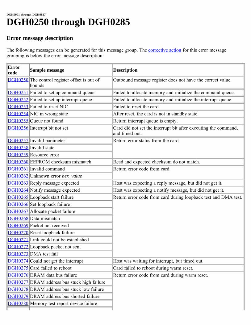
DGH0001 through DGH0827
DGH0250 through DGH0285Error message description
The following messages can be generated for this message group. The corrective action for this error messagegrouping is below the error message description:
Errorcode Sample message Description
DGH0250 The control register offset is out ofbounds
Outbound message register does not have the correct value.
DGH0251 Failed to set up command queue Failed to allocate memory and initialize the command queue.DGH0252 Failed to set up interrupt queue Failed to allocate memory and initialize the interrupt queue.DGH0253 Failed to reset NIC Failed to reset the card.DGH0254 NIC in wrong state After reset, the card is not in standby state.DGH0255 Queue not found Return interrupt queue is empty.DGH0256 Interrupt bit not set Card did not set the interrupt bit after executing the command,
and timed out.DGH0257 Invalid parameter Return error status from the card.DGH0258 Invalid stateDGH0259 Resource errorDGH0260 EEPROM checksum mismatch Read and expected checksum do not match.DGH0261 Invalid command Return error code from card.DGH0262 Unknown error hex_valueDGH0263 Reply message expected Host was expecting a reply message, but did not get it.DGH0264 Notify message expected Host was expecting a notify message, but did not get it.DGH0265 Loopback start failure Return error code from card during loopback test and DMA test.DGH0266 Set loopback failureDGH0267 Allocate packet failureDGH0268 Data mismatchDGH0269 Packet not receivedDGH0270 Reset loopback failureDGH0271 Link could not be establishedDGH0272 Loopback packet not sentDGH0273 DMA test failDGH0274 Could not get the interrupt Host was waiting for interrupt, but timed out.DGH0275 Card failed to reboot Card failed to reboot during warm reset.DGH0276 DRAM data bus failure Return error code from card during warm reset.DGH0277 DRAM address bus stuck high failureDGH0278 DRAM address bus stuck low failureDGH0279 DRAM address bus shorted failureDGH0280 Memory test report device failure
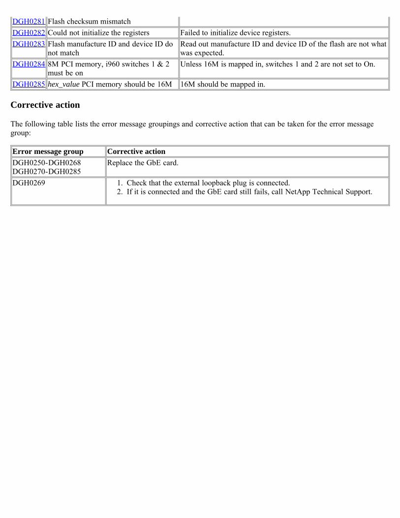
DGH0281 Flash checksum mismatchDGH0282 Could not initialize the registers Failed to initialize device registers.DGH0283 Flash manufacture ID and device ID do
not matchRead out manufacture ID and device ID of the flash are not whatwas expected.
DGH0284 8M PCI memory, i960 switches 1 & 2must be on
Unless 16M is mapped in, switches 1 and 2 are not set to On.
DGH0285 hex_value PCI memory should be 16M 16M should be mapped in.
Corrective action
The following table lists the error message groupings and corrective action that can be taken for the error messagegroup:
Error message group Corrective actionDGH0250-DGH0268DGH0270-DGH0285
Replace the GbE card.
DGH0269 1. Check that the external loopback plug is connected.2. If it is connected and the GbE card still fails, call NetApp Technical Support.
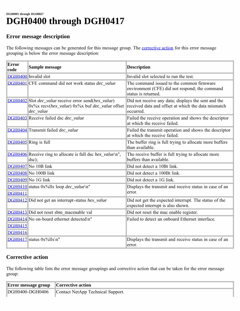
DGH0001 through DGH0827
DGH0400 through DGH0417Error message description
The following messages can be generated for this message group. The corrective action for this error messagegrouping is below the error message description:
Errorcode Sample message Description
DGH0400 Invalid slot Invalid slot selected to run the test.DGH0401 CFE command did not work status dec_value The command issued to the common firmware
environment (CFE) did not respond; the commandstatus is returned.
DGH0402 Slot dec_value receive error send(hex_value)0x%x recv(hex_value) 0x%x buf dec_value offsetdec_value
Did not receive any data; displays the sent and thereceived data and offset at which the data mismatchoccurred.
DGH0403 Receive failed dsc dec_value Failed the receive operation and shows the descriptorat which the receive failed.
DGH0404 Transmit failed dec_value Failed the transmit operation and shows the descriptorat which the receive failed.
DGH0405 Ring is full The buffer ring is full trying to allocate more buffersthan available.
DGH0406 Receive ring to allocate is full dsc hex_value\n",dsc);
The receive buffer is full trying to allocate morebuffers than available.
DGH0407 No 10B link Did not detect a 10Bt link.DGH0408 No 100B link Did not detect a 100Bt link.DGH0409 No 1G link Did not detect a 1G link.DGH0410 status 0x%llx loop dec_value\n" Displays the transmit and receive status in case of an
error.DGH0411DGH0412 Did not get an interrupt-status hex_value Did not get the expected interrupt. The status of the
expected interrupt is also shown.DGH0413 Did not reset sbm_macenable val Did not reset the mac enable register.DGH0414 No on-board ethernet detected\n" Failed to detect an onboard Ethernet interface.DGH0415DGH0416DGH0417 status 0x%llx\n" Displays the transmit and receive status in case of an
error.
Corrective action
The following table lists the error message groupings and corrective action that can be taken for the error messagegroup:
Error message group Corrective actionDGH0400-DGH0406 Contact NetApp Technical Support.

DGH0410-DGH0417DGH0407-DGH0409 1. Check that the external loopback plug is connected.
2. If it is connected and the GbE card still fails, call NetApp Technical Support.
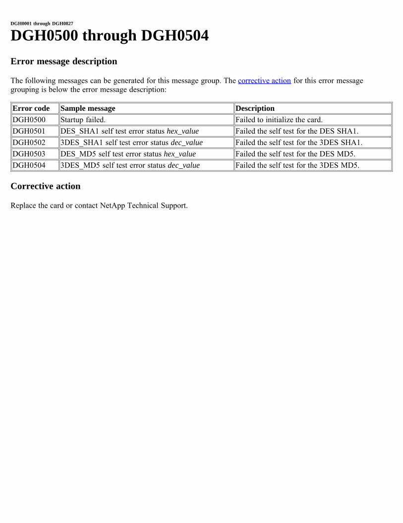
DGH0001 through DGH0827
DGH0500 through DGH0504Error message description
The following messages can be generated for this message group. The corrective action for this error messagegrouping is below the error message description:
Error code Sample message DescriptionDGH0500 Startup failed. Failed to initialize the card.DGH0501 DES_SHA1 self test error status hex_value Failed the self test for the DES SHA1.DGH0502 3DES_SHA1 self test error status dec_value Failed the self test for the 3DES SHA1.DGH0503 DES_MD5 self test error status hex_value Failed the self test for the DES MD5.DGH0504 3DES_MD5 self test error status dec_value Failed the self test for the 3DES MD5.
Corrective action
Replace the card or contact NetApp Technical Support.
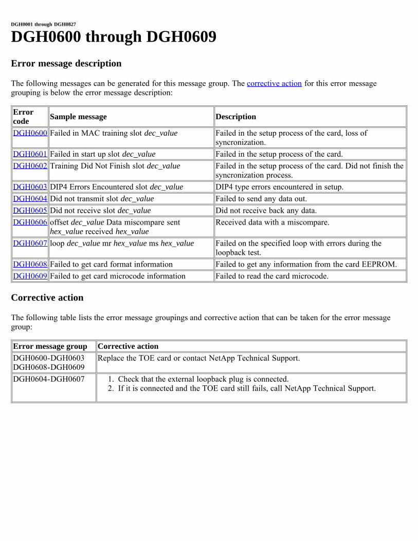
DGH0001 through DGH0827
DGH0600 through DGH0609Error message description
The following messages can be generated for this message group. The corrective action for this error messagegrouping is below the error message description:
Errorcode Sample message Description
DGH0600 Failed in MAC training slot dec_value Failed in the setup process of the card, loss ofsyncronization.
DGH0601 Failed in start up slot dec_value Failed in the setup process of the card.DGH0602 Training Did Not Finish slot dec_value Failed in the setup process of the card. Did not finish the
syncronization process.DGH0603 DIP4 Errors Encountered slot dec_value DIP4 type errors encountered in setup.DGH0604 Did not transmit slot dec_value Failed to send any data out.DGH0605 Did not receive slot dec_value Did not receive back any data.DGH0606 offset dec_value Data miscompare sent
hex_value received hex_valueReceived data with a miscompare.
DGH0607 loop dec_value mr hex_value ms hex_value Failed on the specified loop with errors during theloopback test.
DGH0608 Failed to get card format information Failed to get any information from the card EEPROM.DGH0609 Failed to get card microcode information Failed to read the card microcode.
Corrective action
The following table lists the error message groupings and corrective action that can be taken for the error messagegroup:
Error message group Corrective actionDGH0600-DGH0603DGH0608-DGH0609
Replace the TOE card or contact NetApp Technical Support.
DGH0604-DGH0607 1. Check that the external loopback plug is connected.2. If it is connected and the TOE card still fails, call NetApp Technical Support.
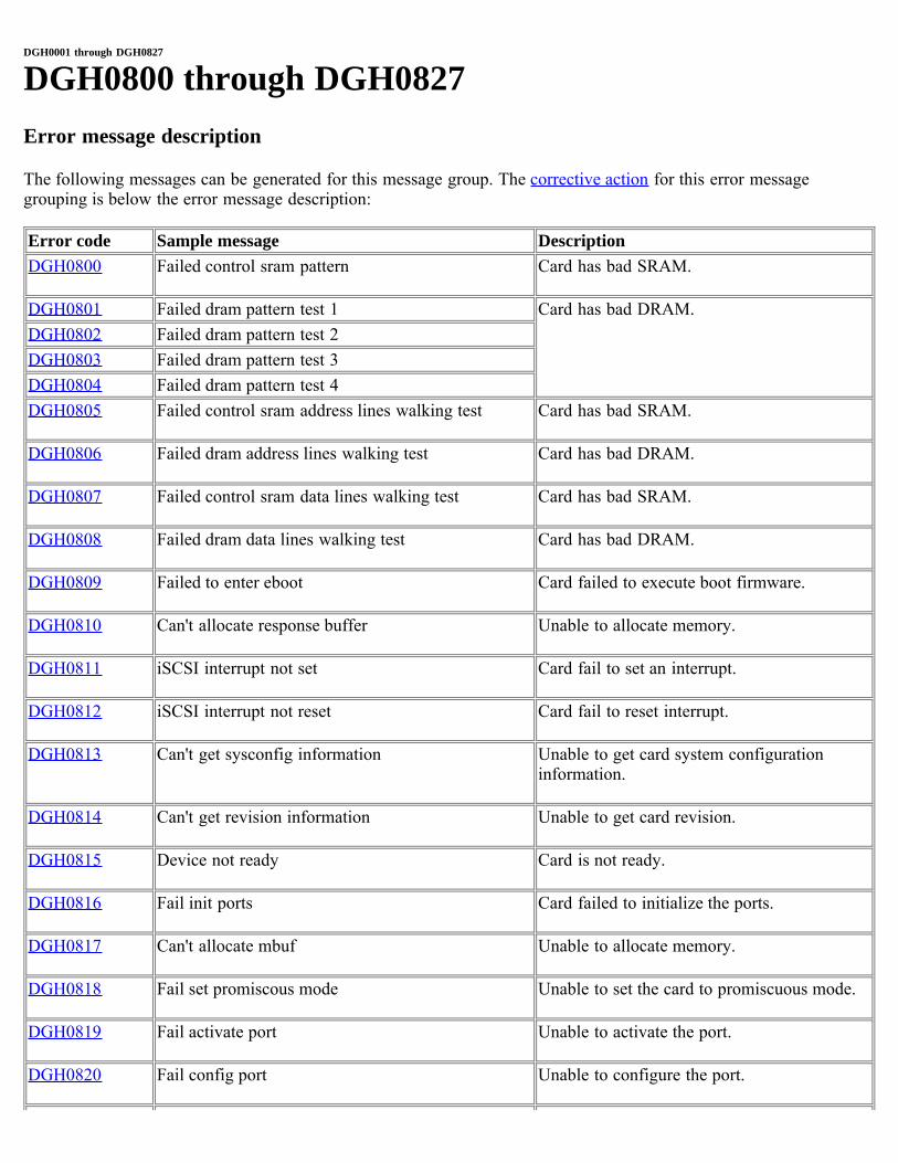
DGH0001 through DGH0827
DGH0800 through DGH0827Error message description
The following messages can be generated for this message group. The corrective action for this error messagegrouping is below the error message description:
Error code Sample message DescriptionDGH0800 Failed control sram pattern Card has bad SRAM.
DGH0801 Failed dram pattern test 1 Card has bad DRAM.DGH0802 Failed dram pattern test 2DGH0803 Failed dram pattern test 3DGH0804 Failed dram pattern test 4DGH0805 Failed control sram address lines walking test Card has bad SRAM.
DGH0806 Failed dram address lines walking test Card has bad DRAM.
DGH0807 Failed control sram data lines walking test Card has bad SRAM.
DGH0808 Failed dram data lines walking test Card has bad DRAM.
DGH0809 Failed to enter eboot Card failed to execute boot firmware.
DGH0810 Can't allocate response buffer Unable to allocate memory.
DGH0811 iSCSI interrupt not set Card fail to set an interrupt.
DGH0812 iSCSI interrupt not reset Card fail to reset interrupt.
DGH0813 Can't get sysconfig information Unable to get card system configurationinformation.
DGH0814 Can't get revision information Unable to get card revision.
DGH0815 Device not ready Card is not ready.
DGH0816 Fail init ports Card failed to initialize the ports.
DGH0817 Can't allocate mbuf Unable to allocate memory.
DGH0818 Fail set promiscous mode Unable to set the card to promiscuous mode.
DGH0819 Fail activate port Unable to activate the port.
DGH0820 Fail config port Unable to configure the port.
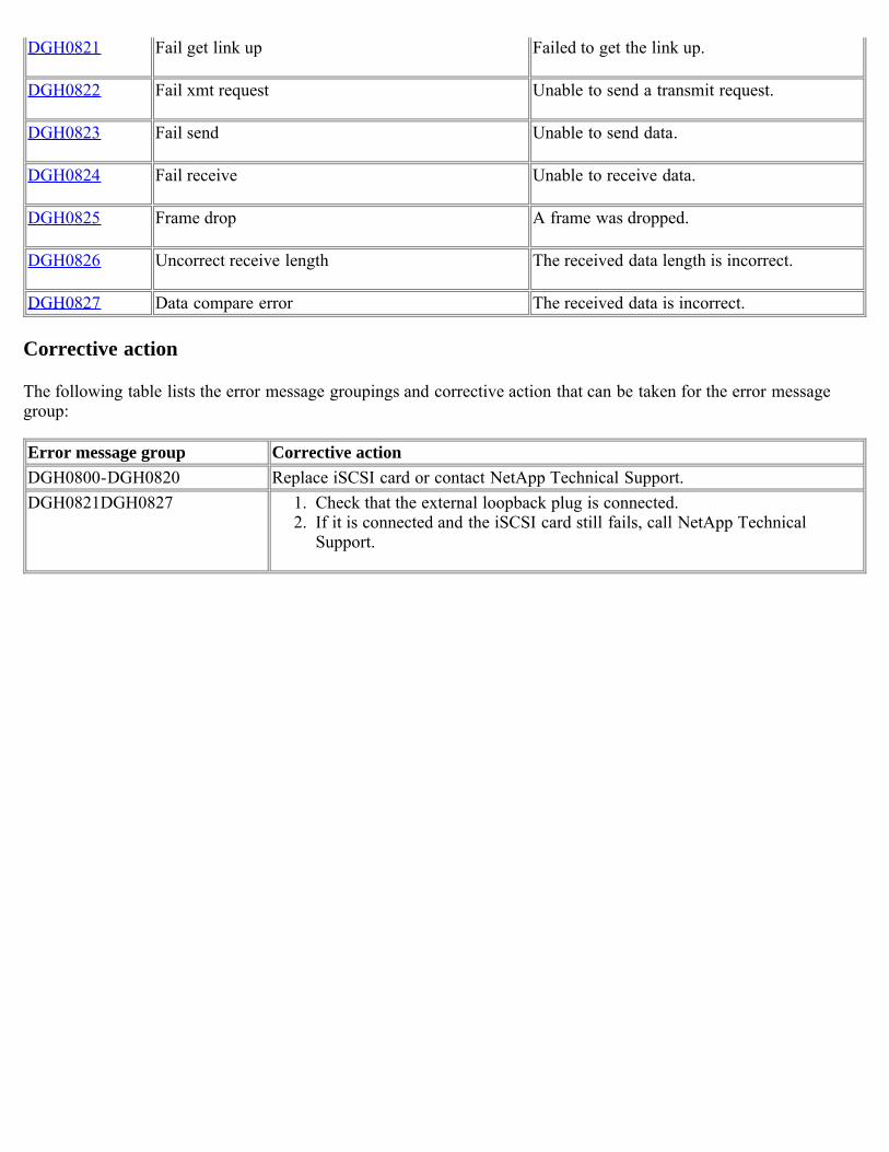
DGH0821 Fail get link up Failed to get the link up.
DGH0822 Fail xmt request Unable to send a transmit request.
DGH0823 Fail send Unable to send data.
DGH0824 Fail receive Unable to receive data.
DGH0825 Frame drop A frame was dropped.
DGH0826 Uncorrect receive length The received data length is incorrect.
DGH0827 Data compare error The received data is incorrect.
Corrective action
The following table lists the error message groupings and corrective action that can be taken for the error messagegroup:
Error message group Corrective actionDGH0800-DGH0820 Replace iSCSI card or contact NetApp Technical Support.DGH0821DGH0827 1. Check that the external loopback plug is connected.
2. If it is connected and the iSCSI card still fails, call NetApp TechnicalSupport.
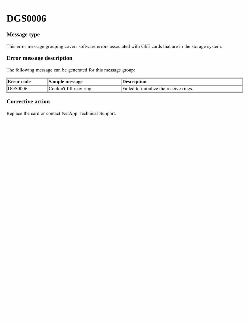
DGS0006Message type
This error message grouping covers software errors associated with GbE cards that are in the storage system.
Error message description
The following message can be generated for this message group:
Error code Sample message DescriptionDGS0006 Couldn't fill recv ring Failed to initialize the receive rings.
Corrective action
Replace the card or contact NetApp Technical Support.
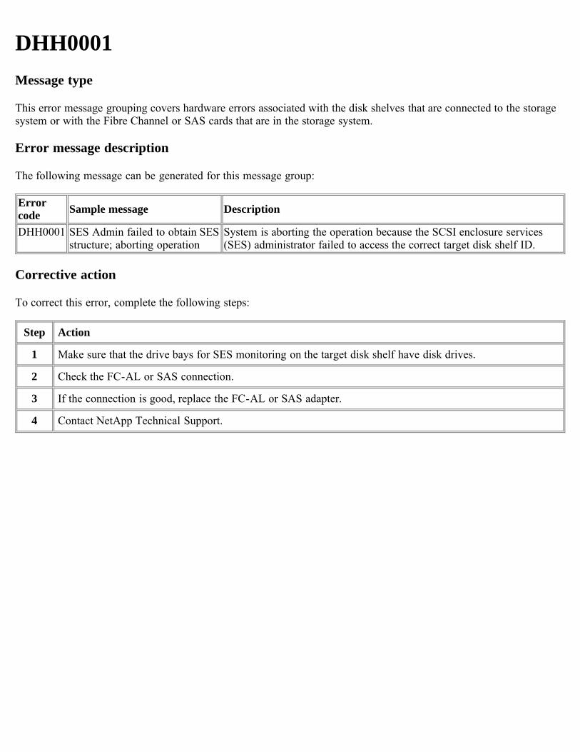
DHH0001Message type
This error message grouping covers hardware errors associated with the disk shelves that are connected to the storagesystem or with the Fibre Channel or SAS cards that are in the storage system.
Error message description
The following message can be generated for this message group:
Errorcode Sample message Description
DHH0001 SES Admin failed to obtain SESstructure; aborting operation
System is aborting the operation because the SCSI enclosure services(SES) administrator failed to access the correct target disk shelf ID.
Corrective action
To correct this error, complete the following steps:
Step Action
1 Make sure that the drive bays for SES monitoring on the target disk shelf have disk drives.
2 Check the FC-AL or SAS connection.
3 If the connection is good, replace the FC-AL or SAS adapter.
4 Contact NetApp Technical Support.
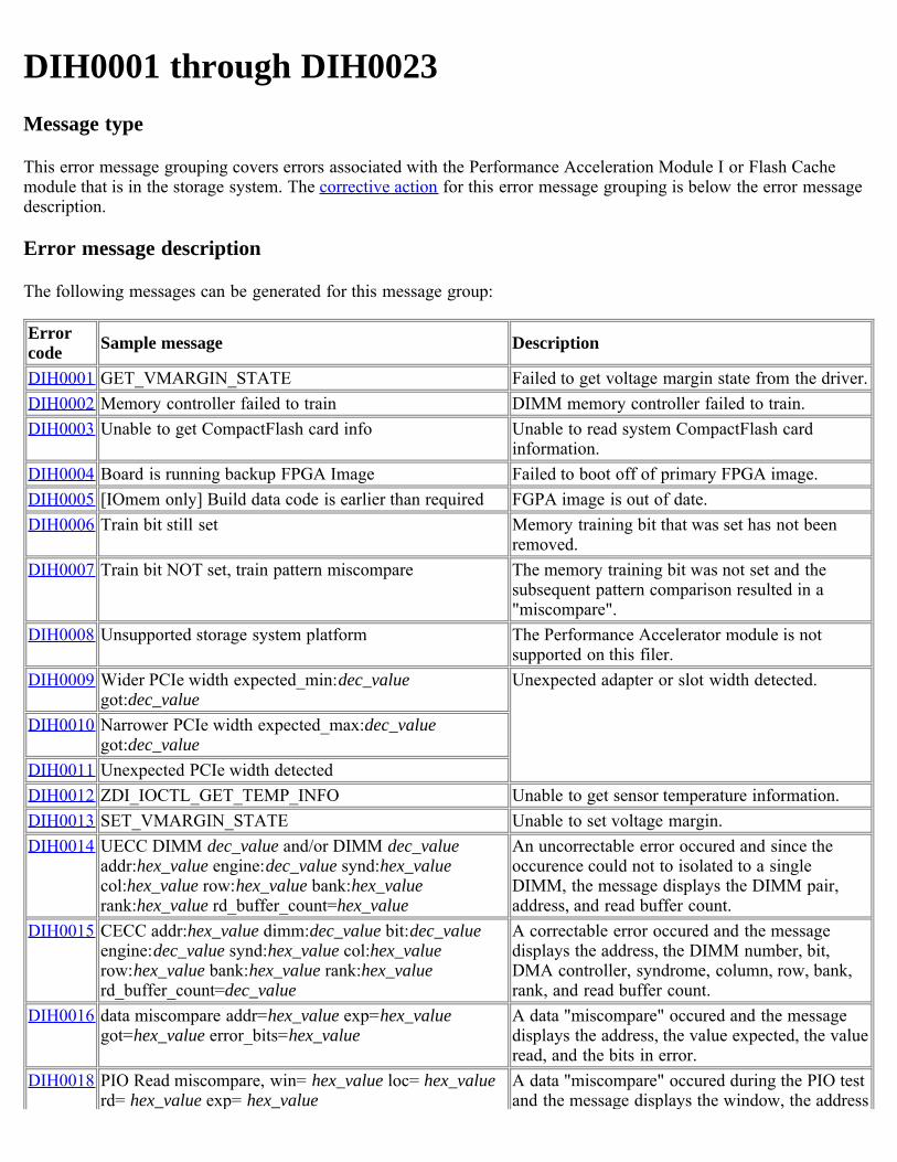
DIH0001 through DIH0023Message type
This error message grouping covers errors associated with the Performance Acceleration Module I or Flash Cachemodule that is in the storage system. The corrective action for this error message grouping is below the error messagedescription.
Error message description
The following messages can be generated for this message group:
Errorcode Sample message Description
DIH0001 GET_VMARGIN_STATE Failed to get voltage margin state from the driver.DIH0002 Memory controller failed to train DIMM memory controller failed to train.DIH0003 Unable to get CompactFlash card info Unable to read system CompactFlash card
information.DIH0004 Board is running backup FPGA Image Failed to boot off of primary FPGA image.DIH0005 [IOmem only] Build data code is earlier than required FGPA image is out of date.DIH0006 Train bit still set Memory training bit that was set has not been
removed.DIH0007 Train bit NOT set, train pattern miscompare The memory training bit was not set and the
subsequent pattern comparison resulted in a"miscompare".
DIH0008 Unsupported storage system platform The Performance Accelerator module is notsupported on this filer.
DIH0009 Wider PCIe width expected_min:dec_valuegot:dec_value
Unexpected adapter or slot width detected.
DIH0010 Narrower PCIe width expected_max:dec_valuegot:dec_value
DIH0011 Unexpected PCIe width detectedDIH0012 ZDI_IOCTL_GET_TEMP_INFO Unable to get sensor temperature information.DIH0013 SET_VMARGIN_STATE Unable to set voltage margin.DIH0014 UECC DIMM dec_value and/or DIMM dec_value
addr:hex_value engine:dec_value synd:hex_valuecol:hex_value row:hex_value bank:hex_valuerank:hex_value rd_buffer_count=hex_value
An uncorrectable error occured and since theoccurence could not to isolated to a singleDIMM, the message displays the DIMM pair,address, and read buffer count.
DIH0015 CECC addr:hex_value dimm:dec_value bit:dec_valueengine:dec_value synd:hex_value col:hex_valuerow:hex_value bank:hex_value rank:hex_valuerd_buffer_count=dec_value
A correctable error occured and the messagedisplays the address, the DIMM number, bit,DMA controller, syndrome, column, row, bank,rank, and read buffer count.
DIH0016 data miscompare addr=hex_value exp=hex_valuegot=hex_value error_bits=hex_value
A data "miscompare" occured and the messagedisplays the address, the value expected, the valueread, and the bits in error.
DIH0018 PIO Read miscompare, win= hex_value loc= hex_valuerd= hex_value exp= hex_value
A data "miscompare" occured during the PIO testand the message displays the window, the address
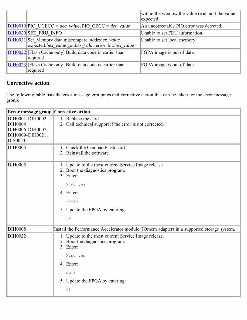
within the window,the value read, and the valueexpected.
DIH0019 PIO_UCECC = dec_value, PIO_CECC = dec_value An uncorrectable PIO error was detected.DIH0020 SET_FRU_INFO Unable to set FRU information.DIH0021 Set_Memory data miscompare, addr:hex_value
expected:hex_value got:hex_value error_bit:hex_valueUnable to set local memory.
DIH0022 [Flash Cache only] Build data code is earlier thanrequired
FGPA image is out of date.
DIH0023 [Flash Cache only] Build data code is earlier thanrequired
FGPA image is out of date.
Corrective action
The following table lists the error message groupings and corrective action that can be taken for the error messagegroup:
Error message group Corrective actionDIH0001-DIH0002DIH0004DIH0006-DIH0007DIH0009-DIH0021,DIS0023
1. Replace the card.2. Call technical support if the error is not corrected.
DIH0003 1. Check the CompactFlash card.2. Reinstall the software.
DIH0005 1. Update to the most current Service Image release.2. Boot the diagnostics program.3. Enter:
Xtnd yes
4. Enter:
iomem
5. Update the FPGA by entering:
62
DIH0008 Install the Performance Accelerator module (IOmem adapter) in a supported storage system.DIH0022 1. Update to the most current Service Image release.
2. Boot the diagnostics program.3. Enter:
Xtnd yes
4. Enter:
pam2
5. Update the FPGA by entering:
61
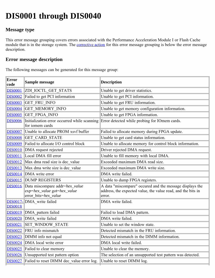
DIS0001 through DIS0040Message type
This error message grouping covers errors associated with the Performance Acceleration Module I or Flash Cachemodule that is in the storage system. The corrective action for this error message grouping is below the error messagedescription.
Error message description
The following messages can be generated for this message group:
Errorcode Sample message Description
DIS0001 ZDI_IOCTL_GET_STATS Unable to get driver statistics.DIS0002 Failed to get PCI information Unable to get PCI information.DIS0003 GET_FRU_INFO Unable to get FRU information.DIS0004 GET_MEMORY_INFO Unable to get memory configuration information.DIS0005 GET_FPGA_INFO Unable to get FPGA information.DIS0006 Initialization error occurred while scanning
for iomem cardsError detected while probing for IOmem cards.
DIS0007 Unable to allocate PROM xsvf buffer Failed to allocate memory during FPGA update.DIS0008 GET_CARD_STATE Unable to get card status information.DIS0009 Failed to allocate I/O control block Unable to allocate memory for control block information.DIS0010 DMA request rejected Driver rejected DMA request.DIS0011 Local DMA fill error Unable to fill memory with local DMA.DIS0012 Max dma read size is dec_value Exceeded maximum DMA read size.DIS0013 Max dma write size is dec_value Exceeded maximum DMA write size.DIS0014 DMA write error DMA write failed.DIS0015 DUMP REGISTERS Unable to dump FPGA registers.DIS0016 Data miscompare addr=hex_value
exp=hex_value got=hex_valueerror_bits=hex_value
A data "miscompare" occured and the message displays theaddress, the expected value, the value read, and the bits inerror.
DIS0017-DIS0018
DMA_write failed DMA write failed.
DIS0019 DMA_pattern failed Failed to load DMA pattern.DIS0020 DMA_write failed DMA write failed.DIS0021 SET_WINDOW_STATE Unable to set the window state.DIS0022 FRU info mismatch Detected mismatch in the FRU information.DIS0023 DIMM info not equal Detected mismatch in the DIMM information.DIS0024 DMA local write error DMA local write failed.DIS0025 Failed to clear memory Unable to clear the memory.DIS0026 Unsupported test pattern option The selection of an unsupported test pattern was detected.DIS0027 Failed to reset DIMM dec_value error log. Unable to reset DIMM log.
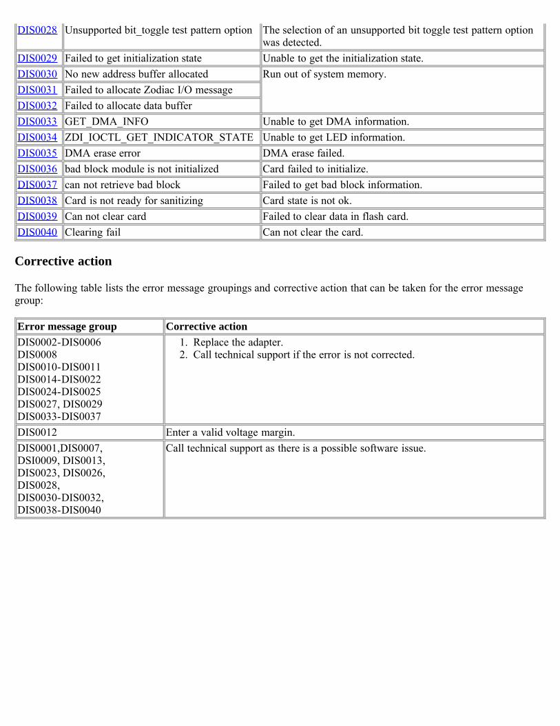
DIS0028 Unsupported bit_toggle test pattern option The selection of an unsupported bit toggle test pattern optionwas detected.
DIS0029 Failed to get initialization state Unable to get the initialization state.DIS0030 No new address buffer allocated Run out of system memory.DIS0031 Failed to allocate Zodiac I/O messageDIS0032 Failed to allocate data bufferDIS0033 GET_DMA_INFO Unable to get DMA information.DIS0034 ZDI_IOCTL_GET_INDICATOR_STATE Unable to get LED information.DIS0035 DMA erase error DMA erase failed.DIS0036 bad block module is not initialized Card failed to initialize.DIS0037 can not retrieve bad block Failed to get bad block information.DIS0038 Card is not ready for sanitizing Card state is not ok.DIS0039 Can not clear card Failed to clear data in flash card.DIS0040 Clearing fail Can not clear the card.
Corrective action
The following table lists the error message groupings and corrective action that can be taken for the error messagegroup:
Error message group Corrective actionDIS0002-DIS0006DIS0008DIS0010-DIS0011DIS0014-DIS0022DIS0024-DIS0025DIS0027, DIS0029DIS0033-DIS0037
1. Replace the adapter.2. Call technical support if the error is not corrected.
DIS0012 Enter a valid voltage margin.DIS0001,DIS0007,DSI0009, DIS0013,DIS0023, DIS0026,DIS0028,DIS0030-DIS0032,DIS0038-DIS0040
Call technical support as there is a possible software issue.
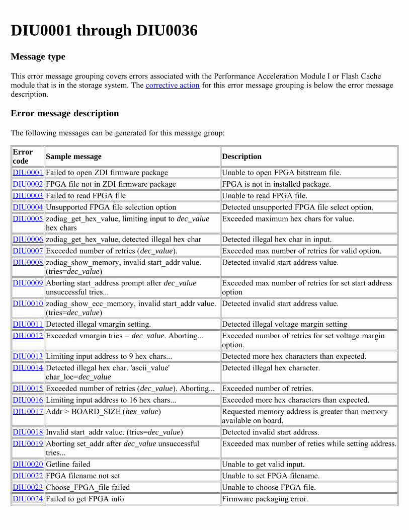
DIU0001 through DIU0036Message type
This error message grouping covers errors associated with the Performance Acceleration Module I or Flash Cachemodule that is in the storage system. The corrective action for this error message grouping is below the error messagedescription.
Error message description
The following messages can be generated for this message group:
Errorcode Sample message Description
DIU0001 Failed to open ZDI firmware package Unable to open FPGA bitstream file.DIU0002 FPGA file not in ZDI firmware package FPGA is not in installed package.DIU0003 Failed to read FPGA file Unable to read FPGA file.DIU0004 Unsupported FPGA file selection option Detected unsupported FPGA file select option.DIU0005 zodiag_get_hex_value, limiting input to dec_value
hex charsExceeded maximum hex chars for value.
DIU0006 zodiag_get_hex_value, detected illegal hex char Detected illegal hex char in input.DIU0007 Exceeded number of retries (dec_value). Exceeded max number of retries for valid option.DIU0008 zodiag_show_memory, invalid start_addr value.
(tries=dec_value)Detected invalid start address value.
DIU0009 Aborting start_address prompt after dec_valueunsuccessful tries...
Exceeded max number of retries for set start addressoption
DIU0010 zodiag_show_ecc_memory, invalid start_addr value.(tries=dec_value)
Detected invalid start address value.
DIU0011 Detected illegal vmargin setting. Detected illegal voltage margin settingDIU0012 Exceeded vmargin tries = dec_value. Aborting... Exceeded number of retries for set voltage margin
option.DIU0013 Limiting input address to 9 hex chars... Detected more hex characters than expected.DIU0014 Detected illegal hex char. 'ascii_value'
char_loc=dec_valueDetected illegal hex character.
DIU0015 Exceeded number of retries (dec_value). Aborting... Exceeded number of retries.DIU0016 Limiting input address to 16 hex chars... Exceeded more hex characters than expected.DIU0017 Addr > BOARD_SIZE (hex_value) Requested memory address is greater than memory
available on board.DIU0018 Invalid start_addr value. (tries=dec_value) Detected invalid start address.DIU0019 Aborting set_addr after dec_value unsuccessful
tries...Exceeded max number of reties while setting address.
DIU0020 Getline failed Unable to get valid input.DIU0022 FPGA filename not set Unable to set FPGA filename.DIU0023 Choose_FPGA_file failed Unable to choose FPGA file.DIU0024 Failed to get FPGA info Firmware packaging error.
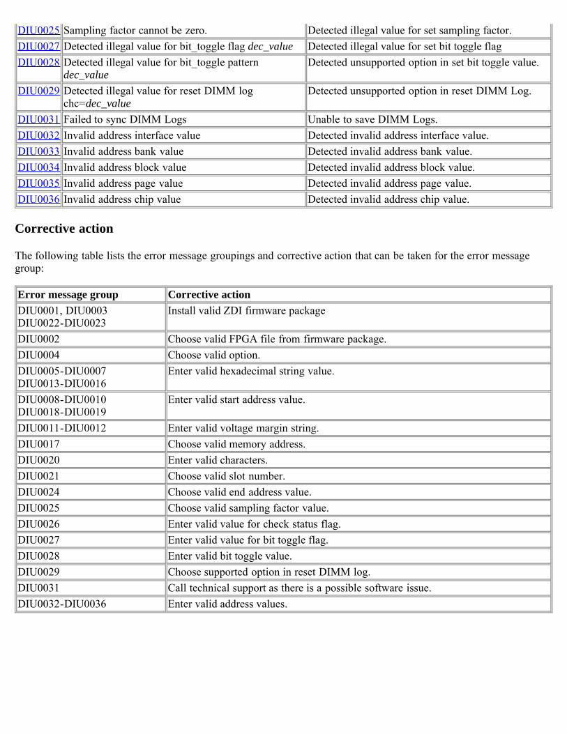
DIU0025 Sampling factor cannot be zero. Detected illegal value for set sampling factor.DIU0027 Detected illegal value for bit_toggle flag dec_value Detected illegal value for set bit toggle flagDIU0028 Detected illegal value for bit_toggle pattern
dec_valueDetected unsupported option in set bit toggle value.
DIU0029 Detected illegal value for reset DIMM logchc=dec_value
Detected unsupported option in reset DIMM Log.
DIU0031 Failed to sync DIMM Logs Unable to save DIMM Logs.DIU0032 Invalid address interface value Detected invalid address interface value.DIU0033 Invalid address bank value Detected invalid address bank value.DIU0034 Invalid address block value Detected invalid address block value.DIU0035 Invalid address page value Detected invalid address page value.DIU0036 Invalid address chip value Detected invalid address chip value.
Corrective action
The following table lists the error message groupings and corrective action that can be taken for the error messagegroup:
Error message group Corrective actionDIU0001, DIU0003DIU0022-DIU0023
Install valid ZDI firmware package
DIU0002 Choose valid FPGA file from firmware package.DIU0004 Choose valid option.DIU0005-DIU0007DIU0013-DIU0016
Enter valid hexadecimal string value.
DIU0008-DIU0010DIU0018-DIU0019
Enter valid start address value.
DIU0011-DIU0012 Enter valid voltage margin string.DIU0017 Choose valid memory address.DIU0020 Enter valid characters.DIU0021 Choose valid slot number.DIU0024 Choose valid end address value.DIU0025 Choose valid sampling factor value.DIU0026 Enter valid value for check status flag.DIU0027 Enter valid value for bit toggle flag.DIU0028 Enter valid bit toggle value.DIU0029 Choose supported option in reset DIMM log.DIU0031 Call technical support as there is a possible software issue.DIU0032-DIU0036 Enter valid address values.
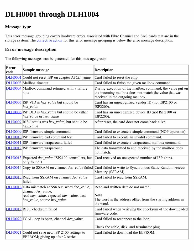
DLH0001 through DLH1004Message type
This error message grouping covers hardware errors associated with Fibre Channel and SAS cards that are in thestorage system. The corrective action for this error message grouping is below the error message description.
Error message description
The following messages can be generated for this message group:
Errorcode Sample message Description
DLH0001 Could not reset ISP on adapter ASCII_value Card failed to reset the chip.DLH0003 Mailbox timeout Card failed to finish the given mailbox command.DLH0004 Mailbox command returned with a failure
noteDuring execution of the mailbox command, the value put onthe incoming mailbox does not match the value that wasreceived in the outgoing mailbox.
DLH0005 ISP VID is hex_value but should behex_value
Card has an unrecognized vendor ID (not ISP2100 orISP2200).
DLH0006 ISP DID is hex_value but should be eitherhex_value or hex_value
Card has an unrecognized device ID (not ISP2100 orISP2200).
DLH0007 RISC status was hex_value, but should behex_value
After reset, the card does not come back alive.
DLH0009 ISP firmware simple command Card failed to execute a simple command (NOP operation).DLH0010 ISP firmware bad command test Card failed to execute an invalid command.DLH0011 ISP firmware wraparound failed Card failed to execute a wraparound mailbox command.DLH0012 ISP firmware wraparound The data transmitted to and received by the mailbox does
not match.DLH0013 Expected dec_value ISP2100 controllers, but
only found 1Card received an unexpected number of ISP chips.
DLH0014 Copy to SSRAM on channel dec_value failed Card failed to write to Synchronous Static Random AccessMemory (SSRAM).
DLH0015 Read from SSRAM on channel dec_valuefailed
Card failed to read from SSRAM.
DLH0016 Data mismatch at SSRAM word dec_value,channel dec_value, read hex_value, expected hex_value, desthex_value, source hex_value
Read and written data do not match.
NoteThe word is the address offset from the starting address inthe word.
DLH0019 RISC checksum failed Card failed when verifying the checksum of the downloadedfirmware code.
DLH0020 FCAL loop is open, channel dec_value Card failed to reconnect to the loop.
Check the cable, disk, and terminator plug.DLH0021 Could not save new ISP 2100 settings to
EEPROM; giving up after 2 retriesCard failed to download the EEPROM.
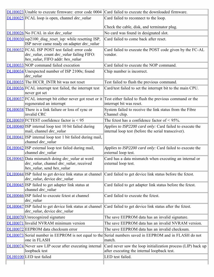
DLH0023 Unable to execute firmware: error code 0004 Card failed to execute the downloaded firmware.DLH0025 FCAL loop is open, channel dec_value Card failed to reconnect to the loop.
Check the cable, disk, and terminator plug.DLH0026 No FCAL in slot dec_value No card was found in designated slot.DLH0030 isp2100_diag_reset_isp: while resetting ISP,
ISP never came ready on adapter dec_valueCard failed to come back after reset.
DLH0032 FCAL ISP POST test failed: error codedec_value, count dec_value failing FIFO:hex_value, FIFO addr: hex_value
Card failed to execute the POST code given by the FC-ALvendor.
DLH0033 NOP command failed execution Card failed to execute the NOP command.DLH0034 Unexpected number of ISP 2100s; found
dec_valueChip number is incorrect.
DLH0035 The HCCR_INTR bit was not reset Test failed to flush the previous command.DLH0036 FCAL interrupt test failed, the interrupt test
never got setCard/test failed to set the interrupt bit to the main CPU.
DLH0037 FCAL interrupt bit either never got reset or itregenerated an interrupt
Test either failed to flush the previous command or theinterrupt bit was reset.
DLH0038 There is a link failure or loss of sync orinvalid CRC
System failed to receive the link status from the FibreChannel chip.
DLH0039 FCTEST confidence factor is < 95 The fctest has a confidence factor of < 95%.DLH0040 ISP internal loop test 10 bit failed during
mail, channel dec_valueApplies to ISP2200 card only: Card failed to execute theinternal loop test (before the serial transceiver).
DLH0041 ISP internal loop test 1 bit failed during mail,channel dec_value
DLH0042 ISP external loop test failed during mail,channel dec_value
Applies to ISP2200 card only: Card failed to execute theexternal loop test.
DLH0043 Data mismatch doing dec_value at worddec_value, channel dec_value, receivedhex_value, send hex_value
Card has a data mismatch when executing an internal orexternal loop test.
DLH0044 ISP failed to get device link status at channeldec_value, device dec_value
Card failed to get device link status before the fctest.
DLH0045 ISP failed to get adapter link status atchannel dec_value
Card failed to get adapter link status before the fctest.
DLH0046 ISP failed to execute fctest at channeldec_value
Card failed to execute the fctest.
DLH0047 ISP failed to get device link status at channeldec_value, device dec_value
Card failed to get device link status after the fctest.
DLH0070 Unrecognized signature The save EEPROM data has an invalid signature.DLH0071 Invalid NVRAM minimum version The save EEPROM data has an invalid NVRAM version.DLH0072 EEPROM data checksum error The save EEPROM data has an invalid checksum.DLH0073 Serial number in EEPROM is not equal to the
one in FLASHSerial numbers saved in EEPROM and in FLASH do notmatch.
DLH0074 Never saw LIP occur after executing internalloopback test
Card never saw the loop initialization process (LIP) back upafter executing the internal loopback test.
DLH0100 LED test failed LED test failed.
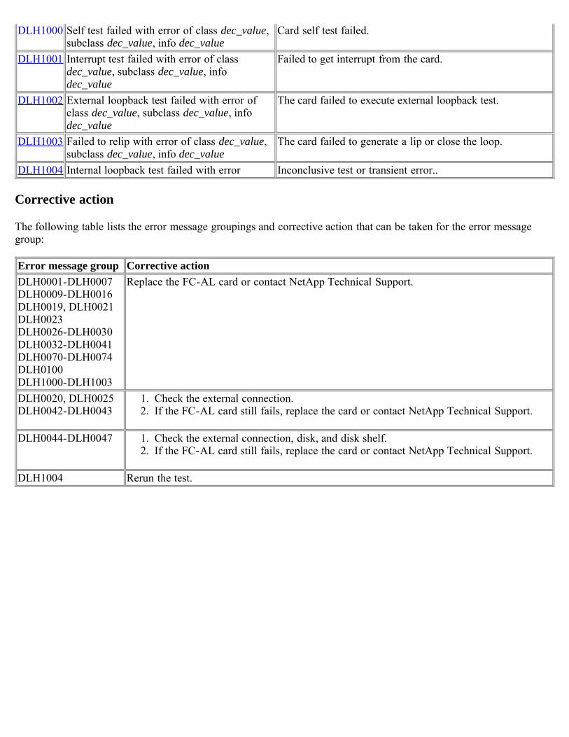
DLH1000 Self test failed with error of class dec_value,subclass dec_value, info dec_value
Card self test failed.
DLH1001 Interrupt test failed with error of classdec_value, subclass dec_value, infodec_value
Failed to get interrupt from the card.
DLH1002 External loopback test failed with error ofclass dec_value, subclass dec_value, infodec_value
The card failed to execute external loopback test.
DLH1003 Failed to relip with error of class dec_value,subclass dec_value, info dec_value
The card failed to generate a lip or close the loop.
DLH1004 Internal loopback test failed with error Inconclusive test or transient error..
Corrective action
The following table lists the error message groupings and corrective action that can be taken for the error messagegroup:
Error message group Corrective actionDLH0001-DLH0007DLH0009-DLH0016DLH0019, DLH0021DLH0023DLH0026-DLH0030DLH0032-DLH0041DLH0070-DLH0074DLH0100DLH1000-DLH1003
Replace the FC-AL card or contact NetApp Technical Support.
DLH0020, DLH0025DLH0042-DLH0043
1. Check the external connection.2. If the FC-AL card still fails, replace the card or contact NetApp Technical Support.
DLH0044-DLH0047 1. Check the external connection, disk, and disk shelf.2. If the FC-AL card still fails, replace the card or contact NetApp Technical Support.
DLH1004 Rerun the test.
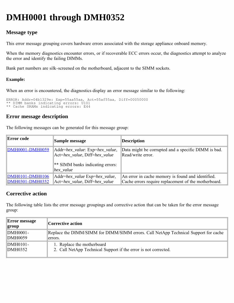
DMH0001 through DMH0352Message type
This error message grouping covers hardware errors associated with the storage appliance onboard memory.
When the memory diagnostics encounter errors, or if recoverable ECC errors occur, the diagnostics attempt to analyzethe error and identify the failing DIMMs.
Bank part numbers are silk-screened on the motherboard, adjacent to the SIMM sockets.
Example:
When an error is encountered, the diagnostics display an error message similar to the following:
ERROR: Addr=04b1329e: Exp=55aa55aa, Act=55af55aa, Diff=00050000** DIMM banks indicating errors: U101** Cache SRAMs indicating errors: E44
Error message description
The following messages can be generated for this message group:
Error code Sample message Description
DMH0001-DMH0059 Addr=hex_value: Exp=hex_value,Act=hex_value, Diff=hex_value
** SIMM banks indicating errors:hex_value
Data might be corrupted and a specific DIMM is bad.Read/write error.
DMH0101-DMH0106DMH0301-DMH0352
Addr=hex_value Exp=hex_value,Act=hex_value, Diff=hex_value
An error in cache memory is found and identified.Cache errors require replacement of the motherboard.
Corrective action
The following table lists the error message groupings and corrective action that can be taken for the error messagegroup:
Error messagegroup Corrective action
DMH0001-DMH0059
Replace the DIMM/SIMM for DIMM/SIMM errors. Call NetApp Technical Support for cacheerrors.
DMH0101-DMH0352
1. Replace the motherboard2. Call NetApp Technical Support if the error is not corrected.
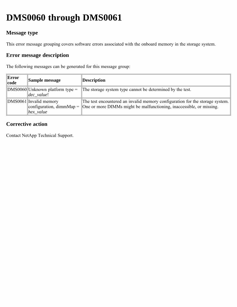
DMS0060 through DMS0061Message type
This error message grouping covers software errors associated with the onboard memory in the storage system.
Error message description
The following messages can be generated for this message group:
Errorcode Sample message Description
DMS0060 Unknown platform type =dec_value!
The storage system type cannot be determined by the test.
DMS0061 Invalid memoryconfiguration, dimmMap =hex_value
The test encountered an invalid memory configuration for the storage system.One or more DIMMs might be malfunctioning, inaccessible, or missing.
Corrective action
Contact NetApp Technical Support.
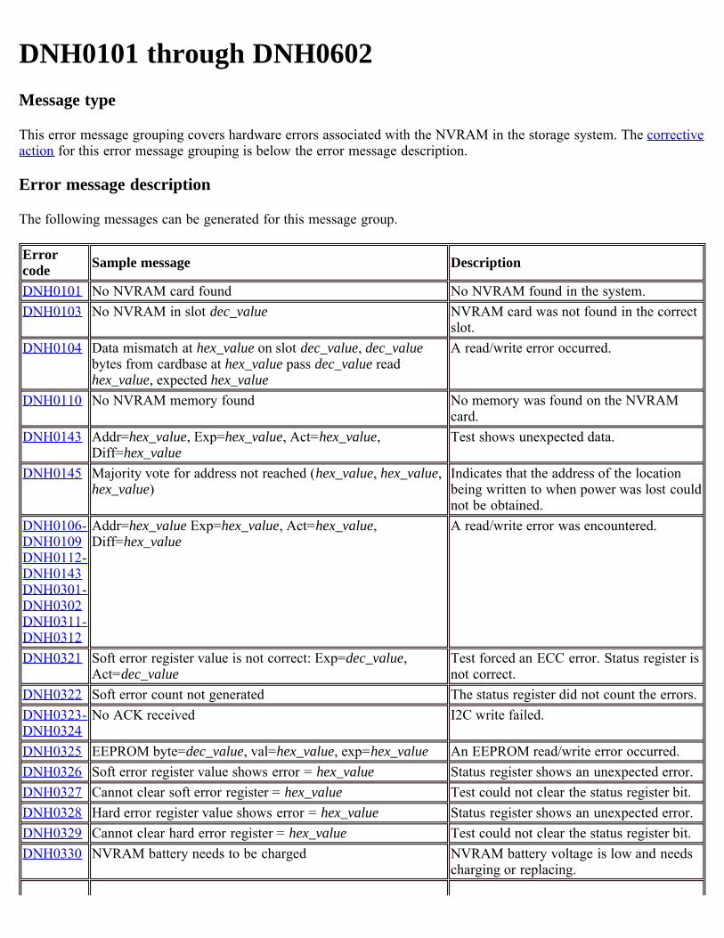
DNH0101 through DNH0602Message type
This error message grouping covers hardware errors associated with the NVRAM in the storage system. The correctiveaction for this error message grouping is below the error message description.
Error message description
The following messages can be generated for this message group.
Errorcode Sample message Description
DNH0101 No NVRAM card found No NVRAM found in the system.DNH0103 No NVRAM in slot dec_value NVRAM card was not found in the correct
slot.DNH0104 Data mismatch at hex_value on slot dec_value, dec_value
bytes from cardbase at hex_value pass dec_value readhex_value, expected hex_value
A read/write error occurred.
DNH0110 No NVRAM memory found No memory was found on the NVRAMcard.
DNH0143 Addr=hex_value, Exp=hex_value, Act=hex_value,Diff=hex_value
Test shows unexpected data.
DNH0145 Majority vote for address not reached (hex_value, hex_value,hex_value)
Indicates that the address of the locationbeing written to when power was lost couldnot be obtained.
DNH0106-DNH0109DNH0112-DNH0143DNH0301-DNH0302DNH0311-DNH0312
Addr=hex_value Exp=hex_value, Act=hex_value,Diff=hex_value
A read/write error was encountered.
DNH0321 Soft error register value is not correct: Exp=dec_value,Act=dec_value
Test forced an ECC error. Status register isnot correct.
DNH0322 Soft error count not generated The status register did not count the errors.DNH0323-DNH0324
No ACK received I2C write failed.
DNH0325 EEPROM byte=dec_value, val=hex_value, exp=hex_value An EEPROM read/write error occurred.DNH0326 Soft error register value shows error = hex_value Status register shows an unexpected error.DNH0327 Cannot clear soft error register = hex_value Test could not clear the status register bit.DNH0328 Hard error register value shows error = hex_value Status register shows an unexpected error.DNH0329 Cannot clear hard error register = hex_value Test could not clear the status register bit.DNH0330 NVRAM battery needs to be charged NVRAM battery voltage is low and needs
charging or replacing.
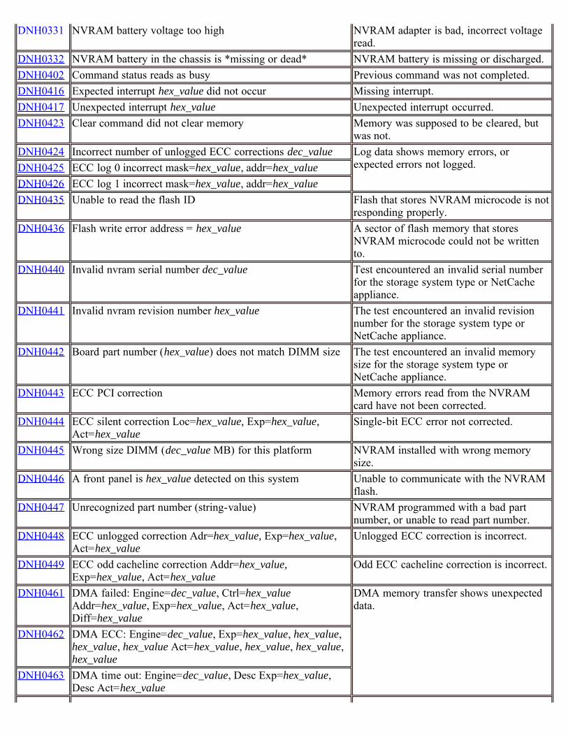
DNH0331 NVRAM battery voltage too high NVRAM adapter is bad, incorrect voltageread.
DNH0332 NVRAM battery in the chassis is *missing or dead* NVRAM battery is missing or discharged.DNH0402 Command status reads as busy Previous command was not completed.DNH0416 Expected interrupt hex_value did not occur Missing interrupt.DNH0417 Unexpected interrupt hex_value Unexpected interrupt occurred.DNH0423 Clear command did not clear memory Memory was supposed to be cleared, but
was not.DNH0424 Incorrect number of unlogged ECC corrections dec_value Log data shows memory errors, or
expected errors not logged.DNH0425 ECC log 0 incorrect mask=hex_value, addr=hex_valueDNH0426 ECC log 1 incorrect mask=hex_value, addr=hex_valueDNH0435 Unable to read the flash ID Flash that stores NVRAM microcode is not
responding properly.DNH0436 Flash write error address = hex_value A sector of flash memory that stores
NVRAM microcode could not be writtento.
DNH0440 Invalid nvram serial number dec_value Test encountered an invalid serial numberfor the storage system type or NetCacheappliance.
DNH0441 Invalid nvram revision number hex_value The test encountered an invalid revisionnumber for the storage system type orNetCache appliance.
DNH0442 Board part number (hex_value) does not match DIMM size The test encountered an invalid memorysize for the storage system type orNetCache appliance.
DNH0443 ECC PCI correction Memory errors read from the NVRAMcard have not been corrected.
DNH0444 ECC silent correction Loc=hex_value, Exp=hex_value,Act=hex_value
Single-bit ECC error not corrected.
DNH0445 Wrong size DIMM (dec_value MB) for this platform NVRAM installed with wrong memorysize.
DNH0446 A front panel is hex_value detected on this system Unable to communicate with the NVRAMflash.
DNH0447 Unrecognized part number (string-value) NVRAM programmed with a bad partnumber, or unable to read part number.
DNH0448 ECC unlogged correction Adr=hex_value, Exp=hex_value,Act=hex_value
Unlogged ECC correction is incorrect.
DNH0449 ECC odd cacheline correction Addr=hex_value,Exp=hex_value, Act=hex_value
Odd ECC cacheline correction is incorrect.
DNH0461 DMA failed: Engine=dec_value, Ctrl=hex_valueAddr=hex_value, Exp=hex_value, Act=hex_value,Diff=hex_value
DMA memory transfer shows unexpecteddata.
DNH0462 DMA ECC: Engine=dec_value, Exp=hex_value, hex_value,hex_value, hex_value Act=hex_value, hex_value, hex_value,hex_value
DNH0463 DMA time out: Engine=dec_value, Desc Exp=hex_value,Desc Act=hex_value
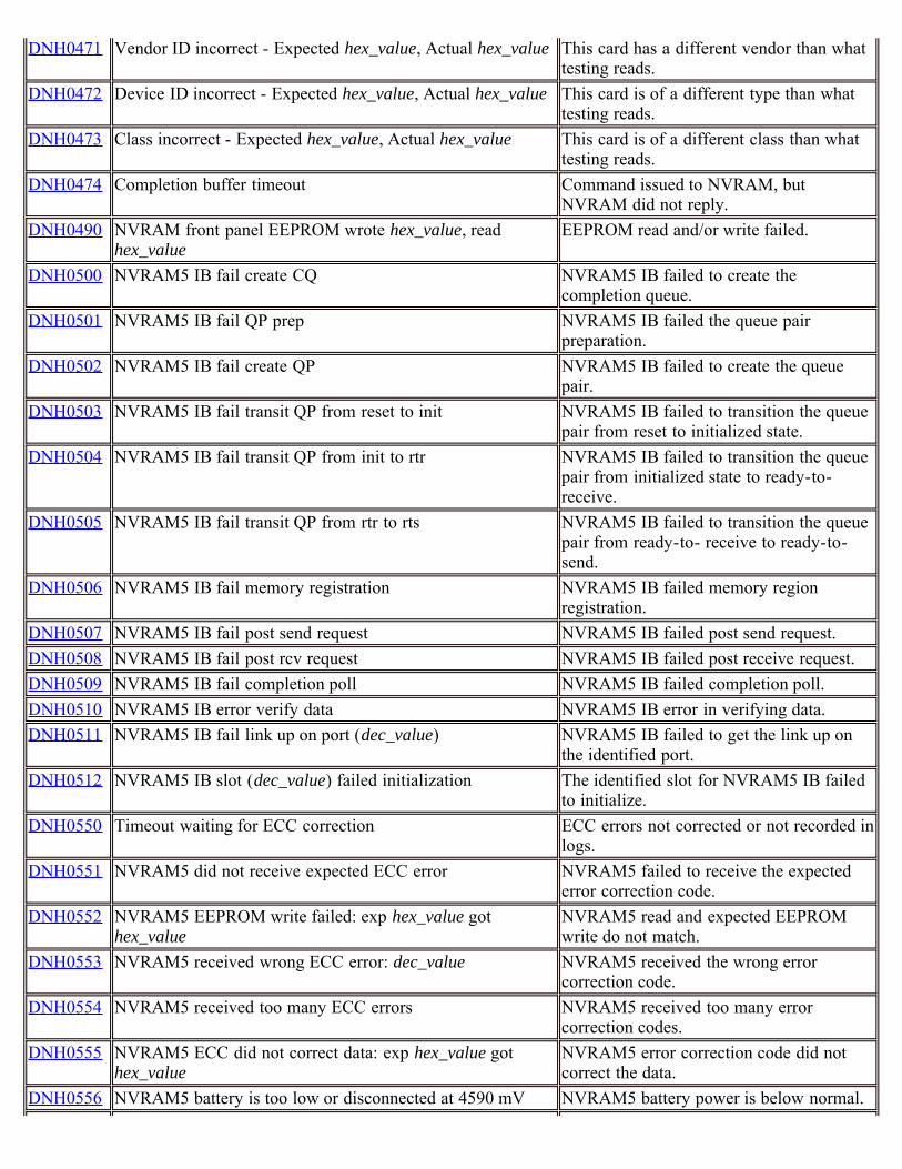
DNH0471 Vendor ID incorrect - Expected hex_value, Actual hex_value This card has a different vendor than whattesting reads.
DNH0472 Device ID incorrect - Expected hex_value, Actual hex_value This card is of a different type than whattesting reads.
DNH0473 Class incorrect - Expected hex_value, Actual hex_value This card is of a different class than whattesting reads.
DNH0474 Completion buffer timeout Command issued to NVRAM, butNVRAM did not reply.
DNH0490 NVRAM front panel EEPROM wrote hex_value, readhex_value
EEPROM read and/or write failed.
DNH0500 NVRAM5 IB fail create CQ NVRAM5 IB failed to create thecompletion queue.
DNH0501 NVRAM5 IB fail QP prep NVRAM5 IB failed the queue pairpreparation.
DNH0502 NVRAM5 IB fail create QP NVRAM5 IB failed to create the queuepair.
DNH0503 NVRAM5 IB fail transit QP from reset to init NVRAM5 IB failed to transition the queuepair from reset to initialized state.
DNH0504 NVRAM5 IB fail transit QP from init to rtr NVRAM5 IB failed to transition the queuepair from initialized state to ready-to-receive.
DNH0505 NVRAM5 IB fail transit QP from rtr to rts NVRAM5 IB failed to transition the queuepair from ready-to- receive to ready-to-send.
DNH0506 NVRAM5 IB fail memory registration NVRAM5 IB failed memory regionregistration.
DNH0507 NVRAM5 IB fail post send request NVRAM5 IB failed post send request.DNH0508 NVRAM5 IB fail post rcv request NVRAM5 IB failed post receive request.DNH0509 NVRAM5 IB fail completion poll NVRAM5 IB failed completion poll.DNH0510 NVRAM5 IB error verify data NVRAM5 IB error in verifying data.DNH0511 NVRAM5 IB fail link up on port (dec_value) NVRAM5 IB failed to get the link up on
the identified port.DNH0512 NVRAM5 IB slot (dec_value) failed initialization The identified slot for NVRAM5 IB failed
to initialize.DNH0550 Timeout waiting for ECC correction ECC errors not corrected or not recorded in
logs.DNH0551 NVRAM5 did not receive expected ECC error NVRAM5 failed to receive the expected
error correction code.DNH0552 NVRAM5 EEPROM write failed: exp hex_value got
hex_valueNVRAM5 read and expected EEPROMwrite do not match.
DNH0553 NVRAM5 received wrong ECC error: dec_value NVRAM5 received the wrong errorcorrection code.
DNH0554 NVRAM5 received too many ECC errors NVRAM5 received too many errorcorrection codes.
DNH0555 NVRAM5 ECC did not correct data: exp hex_value gothex_value
NVRAM5 error correction code did notcorrect the data.
DNH0556 NVRAM5 battery is too low or disconnected at 4590 mV NVRAM5 battery power is below normal.
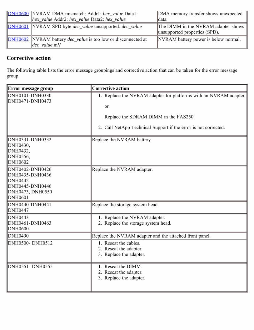
DNH0600 NVRAM DMA mismatch: Addr1: hex_value Data1:hex_value Addr2: hex_value Data2: hex_value
DMA memory transfer shows unexpecteddata
DNH0601 NVRAM SPD byte dec_value unsupported: dec_value The DIMM in the NVRAM adapter showsunsupported properties (SPD).
DNH0602 NVRAM battery dec_value is too low or disconnected atdec_value mV
NVRAM battery power is below normal.
Corrective action
The following table lists the error message groupings and corrective action that can be taken for the error messagegroup.
Error message group Corrective actionDNH0101-DNH0330DNH0471-DNH0473
1. Replace the NVRAM adapter for platforms with an NVRAM adapter
or
Replace the SDRAM DIMM in the FAS250.
2. Call NetApp Technical Support if the error is not corrected.
DNH0331-DNH0332DNH0430, DNH0432, DNH0556,DNH0602
Replace the NVRAM battery.
DNH0402-DNH0426DNH0435-DNH0436DNH0442DNH0445-DNH0446DNH0473, DNH0550DNH0601
Replace the NVRAM adapter.
DNH0440-DNH0441DNH0447
Replace the storage system head.
DNH0443DNH0461-DNH0463DNH0600
1. Replace the NVRAM adapter.2. Replace the storage system head.
DNH0490 Replace the NVRAM adapter and the attached front panel.DNH0500- DNH0512 1. Reseat the cables.
2. Reseat the adapter.3. Replace the adapter.
DNH0551- DNH0555 1. Reseat the DIMM.2. Reseat the adapter.3. Replace the adapter.
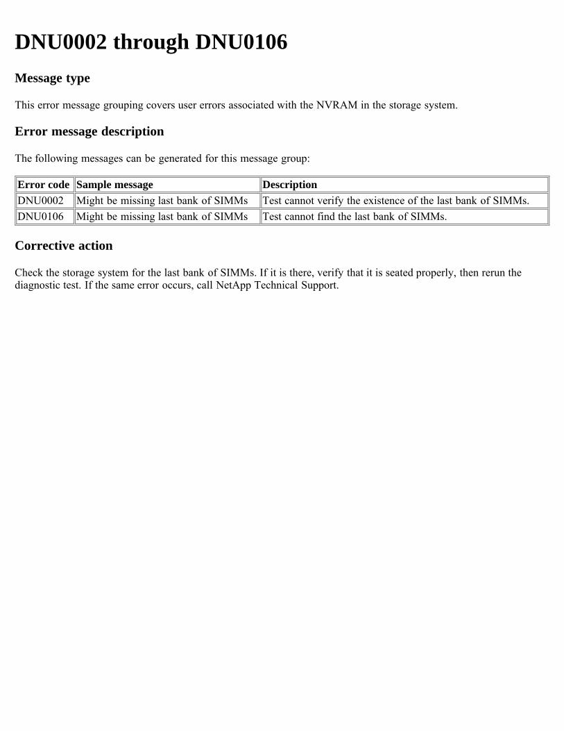
DNU0002 through DNU0106Message type
This error message grouping covers user errors associated with the NVRAM in the storage system.
Error message description
The following messages can be generated for this message group:
Error code Sample message DescriptionDNU0002 Might be missing last bank of SIMMs Test cannot verify the existence of the last bank of SIMMs.DNU0106 Might be missing last bank of SIMMs Test cannot find the last bank of SIMMs.
Corrective action
Check the storage system for the last bank of SIMMs. If it is there, verify that it is seated properly, then rerun thediagnostic test. If the same error occurs, call NetApp Technical Support.
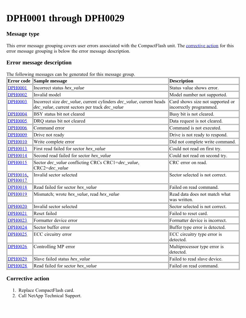
DPH0001 through DPH0029Message type
This error message grouping covers user errors associated with the CompactFlash unit. The corrective action for thiserror message grouping is below the error message description.
Error message description
The following messages can be generated for this message group.Error code Sample message DescriptionDPH0001 Incorrect status hex_value Status value shows error.DPH0002 Invalid model Model number not supported.DPH0003 Incorrect size dec_value, current cylinders dec_value, current heads
dec_value, current sectors per track dec_valueCard shows size not supported orincorrectly programmed.
DPH0004 BSY status bit not cleared Busy bit is not cleared.DPH0005 DRQ status bit not cleared Data request is not cleared.DPH0006 Command error Command is not executed.DPH0009 Drive not ready Drive is not ready to respond.DPH0010 Write complete error Did not complete write command.DPH0013 First read failed for sector hex_value Could not read on first try.DPH0014 Second read failed for sector hex_value Could not read on second try.DPH0015 Sector dec_value conflicting CRCs CRC1=dec_value,
CRC2=dec_valueCRC error on read.
DPH0016,DPH0017
Invalid sector selected Sector selected is not correct.
DPH0018 Read failed for sector hex_value Failed on read command.DPH0019 Mismatch; wrote hex_value, read hex_value Read data does not match what
was written.DPH0020 Invalid sector selected Sector selected is not correct.DPH0021 Reset failed Failed to reset card.DPH0023 Formatter device error Formatter device is incorrect.DPH0024 Sector buffer error Buffer type error is detected.DPH0025 ECC circuitry error ECC circuitry type error is
detected.DPH0026 Controlling MP error Multiprocessor type error is
detected.DPH0029 Slave failed status hex_value Failed to read slave device.DPH0028 Read failed for sector hex_value Failed on read command.
Corrective action
1. Replace CompactFlash card.2. Call NetApp Technical Support.
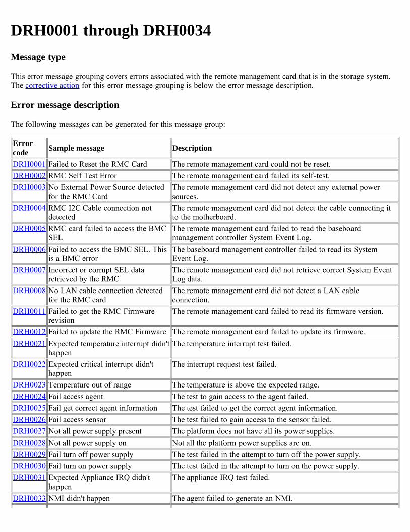
DRH0001 through DRH0034Message type
This error message grouping covers errors associated with the remote management card that is in the storage system.The corrective action for this error message grouping is below the error message description.
Error message description
The following messages can be generated for this message group:
Errorcode Sample message Description
DRH0001 Failed to Reset the RMC Card The remote management card could not be reset.DRH0002 RMC Self Test Error The remote management card failed its self-test.DRH0003 No External Power Source detected
for the RMC CardThe remote management card did not detect any external powersources.
DRH0004 RMC I2C Cable connection notdetected
The remote management card did not detect the cable connecting itto the motherboard.
DRH0005 RMC card failed to access the BMCSEL
The remote management card failed to read the baseboardmanagement controller System Event Log.
DRH0006 Failed to access the BMC SEL. Thisis a BMC error
The baseboard management controller failed to read its SystemEvent Log.
DRH0007 Incorrect or corrupt SEL dataretrieved by the RMC
The remote management card did not retrieve correct System EventLog data.
DRH0008 No LAN cable connection detectedfor the RMC card
The remote management card did not detect a LAN cableconnection.
DRH0011 Failed to get the RMC Firmwarerevision
The remote management card failed to read its firmware version.
DRH0012 Failed to update the RMC Firmware The remote management card failed to update its firmware.DRH0021 Expected temperature interrupt didn't
happenThe temperature interrupt test failed.
DRH0022 Expected critical interrupt didn'thappen
The interrupt request test failed.
DRH0023 Temperature out of range The temperature is above the expected range.DRH0024 Fail access agent The test to gain access to the agent failed.DRH0025 Fail get correct agent information The test failed to get the correct agent information.DRH0026 Fail access sensor The test failed to gain access to the sensor failed.DRH0027 Not all power supply present The platform does not have all its power supplies.DRH0028 Not all power supply on Not all the platform power supplies are on.DRH0029 Fail turn off power supply The test failed in the attempt to turn off the power supply.DRH0030 Fail turn on power supply The test failed in the attempt to turn on the power supply.DRH0031 Expected Appliance IRQ didn't
happenThe appliance IRQ test failed.
DRH0033 NMI didn't happen The agent failed to generate an NMI.
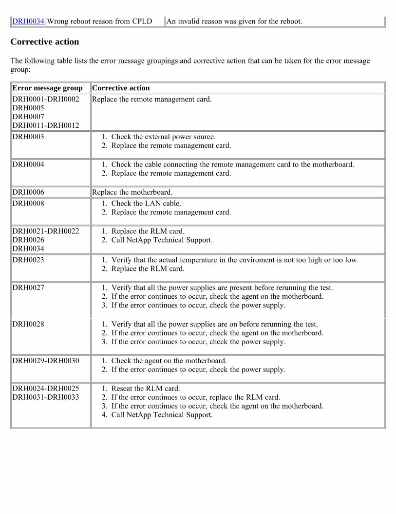
DRH0034 Wrong reboot reason from CPLD An invalid reason was given for the reboot.
Corrective action
The following table lists the error message groupings and corrective action that can be taken for the error messagegroup:
Error message group Corrective actionDRH0001-DRH0002DRH0005DRH0007DRH0011-DRH0012
Replace the remote management card.
DRH0003 1. Check the external power source.2. Replace the remote management card.
DRH0004 1. Check the cable connecting the remote management card to the motherboard.2. Replace the remote management card.
DRH0006 Replace the motherboard.DRH0008 1. Check the LAN cable.
2. Replace the remote management card.
DRH0021-DRH0022DRH0026DRH0034
1. Replace the RLM card.2. Call NetApp Technical Support.
DRH0023 1. Verify that the actual temperature in the enviroment is not too high or too low.2. Replace the RLM card.
DRH0027 1. Verify that all the power supplies are present before rerunning the test.2. If the error continues to occur, check the agent on the motherboard.3. If the error continues to occur, check the power supply.
DRH0028 1. Verify that all the power supplies are on before rerunning the test.2. If the error continues to occur, check the agent on the motherboard.3. If the error continues to occur, check the power supply.
DRH0029-DRH0030 1. Check the agent on the motherboard.2. If the error continues to occur, check the power supply.
DRH0024-DRH0025DRH0031-DRH0033
1. Reseat the RLM card.2. If the error continues to occur, replace the RLM card.3. If the error continues to occur, check the agent on the motherboard.4. Call NetApp Technical Support.
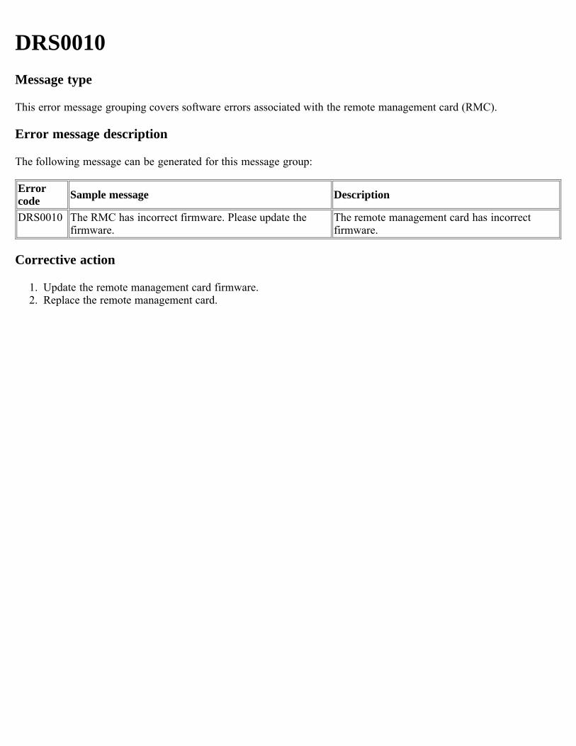
DRS0010Message type
This error message grouping covers software errors associated with the remote management card (RMC).
Error message description
The following message can be generated for this message group:
Errorcode Sample message Description
DRS0010 The RMC has incorrect firmware. Please update thefirmware.
The remote management card has incorrectfirmware.
Corrective action
1. Update the remote management card firmware.2. Replace the remote management card.
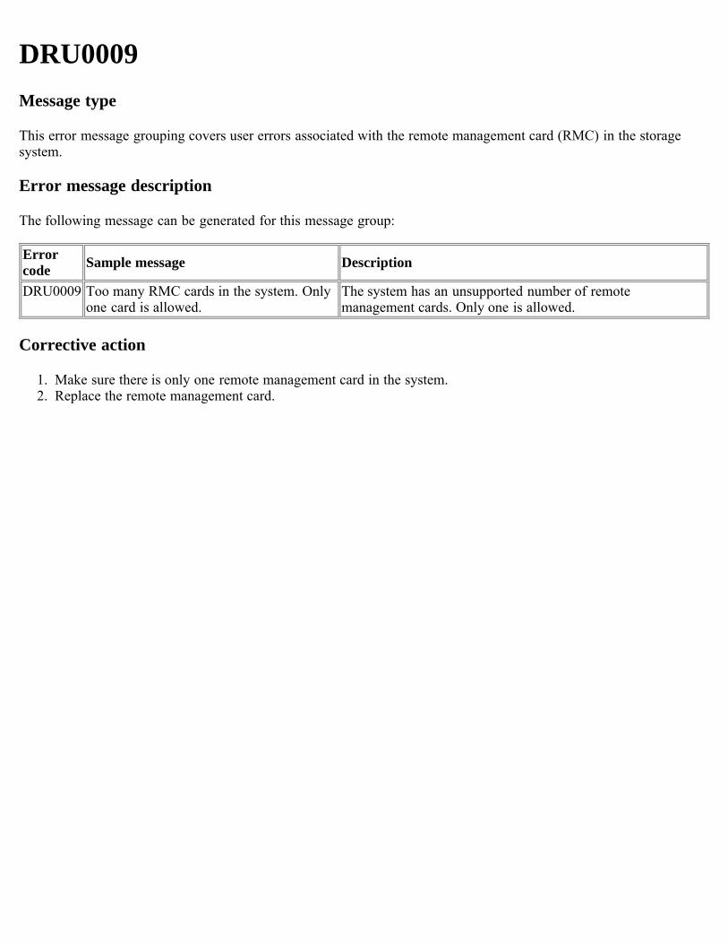
DRU0009Message type
This error message grouping covers user errors associated with the remote management card (RMC) in the storagesystem.
Error message description
The following message can be generated for this message group:
Errorcode Sample message Description
DRU0009 Too many RMC cards in the system. Onlyone card is allowed.
The system has an unsupported number of remotemanagement cards. Only one is allowed.
Corrective action
1. Make sure there is only one remote management card in the system. 2. Replace the remote management card.
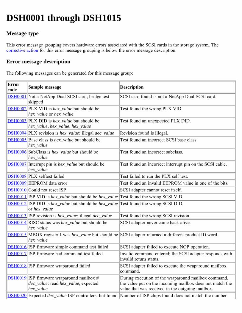
DSH0001 through DSH1015Message type
This error message grouping covers hardware errors associated with the SCSI cards in the storage system. Thecorrective action for this error message grouping is below the error message description.
Error message description
The following messages can be generated for this message group:
Errorcode Sample message Description
DSH0001 Not a NetApp Dual SCSI card; bridge testskipped
SCSI card found is not a NetApp Dual SCSI card.
DSH0002 PLX VID is hex_value but should behex_value or hex_value
Test found the wrong PLX VID.
DSH0003 PLX DID is hex_value but should behex_value, hex_value, hex_value
Test found an unexpected PLX DID.
DSH0004 PLX revision is hex_value; illegal dec_value Revision found is illegal.DSH0005 Base class is hex_value but should be
hex_valueTest found an incorrect SCSI base class.
DSH0006 SubClass is hex_value but should behex_value
Test found an incorrect subclass.
DSH0007 Interrupt pin is hex_value but should behex_value
Test found an incorrect interrupt pin on the SCSI cable.
DSH0008 PLX selftest failed Test failed to run the PLX self test.DSH0009 EEPROM data error Test found an invalid EEPROM value in one of the bits.DSH0010 Could not reset ISP SCSI adapter cannot reset itself.DSH0011 ISP VID is hex_value but should be hex_value Test found the wrong SCSI VID.DSH0012 ISP DID is hex_value but should be hex_value
or hex_valueTest found the wrong SCSI DID.
DSH0013 ISP revision is hex_value; illegal dec_value Test found the wrong SCSI revision.DSH0014 RISC status was hex_value but should be
hex_valueSCSI adapter never came back alive.
DSH0015 MBOX register 1 was hex_value but should behex_value
SCSI adapter returned a different product ID word.
DSH0016 ISP firmware simple command test failed SCSI adapter failed to execute NOP operation.DSH0017 ISP firmware bad command test failed Invalid command entered; the SCSI adapter responds with
invalid return status.DSH0018 ISP firmware wraparound failed SCSI adapter failed to execute the wraparound mailbox
command.DSH0019 ISP firmware wraparound mailbox #
dec_value: read hex_value, expectedhex_value
During execution of the wraparound mailbox command,the value put on the incoming mailbox does not match thevalue that was received in the outgoing mailbox.
DSH0020 Expected dec_value ISP controllers, but found Number of ISP chips found does not match the number
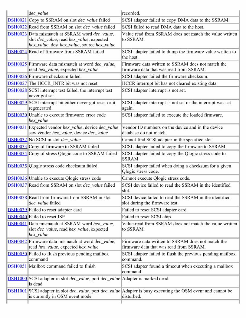
dec_value recorded.DSH0021 Copy to SSRAM on slot dec_value failed SCSI adapter failed to copy DMA data to the SSRAM.DSH0022 Read from SSRAM on slot dec_value failed SCSI failed to read DMA data to the host.DSH0023 Data mismatch at SSRAM word dec_value,
slot dec_value, read hex_value, expectedhex_value, dest hex_value, source hex_value
Value read from SSRAM does not match the value writtento SSRAM.
DSH0024 Read of firmware from SSRAM failed SCSI adapter failed to dump the firmware value written tothe host.
DSH0025 Firmware data mismatch at word dec_value,read hex_value, expected hex_value
Firmware data written to SSRAM does not match thefirmware data that was read from SSRAM.
DSH0026 Firmware checksum failed SCSI adapter failed the firmware checksum.DSH0027 The HCCR_INTR bit was not reset HCCR interrupt bit has not cleared existing data.DSH0028 SCSI interrupt test failed, the interrupt test
never got setSCSI adapter interrupt is not set.
DSH0029 SCSI interrupt bit either never got reset or itregenerated
SCSI adapter interrupt is not set or the interrupt was setagain.
DSH0030 Unable to execute firmware: error codehex_value
SCSI adapter failed to execute the loaded firmware.
DSH0031 Expected vendor hex_value, device dec_valuesaw vendor hex_value, device dec_value
Vendor ID numbers on the device and in the devicedatabase do not match.
DSH0032 No SCSI in slot dec_value Cannot find SCSI adapter in the specified slot.DSH0033 Copy of firmware to SSRAM failed SCSI adapter failed to copy the firmware to SSRAM.DSH0034 Copy of stress Qlogic code to SSRAM failed SCSI adapter failed to copy the Qlogic stress code to
SSRAM.DSH0035 Qlogic stress code checksum failed SCSI adapter failed when doing a checksum for a given
Qlogic stress code.DSH0036 Unable to execute Qlogic stress code Cannot execute Qlogic stress code.DSH0037 Read from SSRAM on slot dec_value failed SCSI device failed to read the SSRAM in the identified
slot.DSH0038 Read from firmware from SSRAM in slot
dec_value failedSCSI device failed to read the SSRAM in the identifiedslot during the firmware test.
DSH0039 Failed to reset adapter card Failed to reset SCSI adapter card.DSH0040 Failed to reset ISP Failed to reset SCSI chip.DSH0041 Data mismatch at SSRAM word hex_value,
slot dec_value, read hex_value, expectedhex_value
Value read from SSRAM does not match the value writtento SSRAM.
DSH0042 Firmware data mismatch at word dec_value,read hex_value, expected hex_value
Firmware data written to SSRAM does not match thefirmware data that was read from SSRAM.
DSH0050 Failed to flush previous pending mailboxcommand
SCSI adapter failed to flush the previous pending mailboxcommand.
DSH0051 Mailbox command failed to finish SCSI adapter found a timeout when executing a mailboxcommand.
DSH1000 SCSI adapter in slot dec_value, port dec_valueis dead
Adapter is marked dead.
DSH1001 SCSI adapter in slot dec_value, port dec_valueis currently in OSM event mode
Adapter is busy executing the OSM event and cannot bedisturbed.
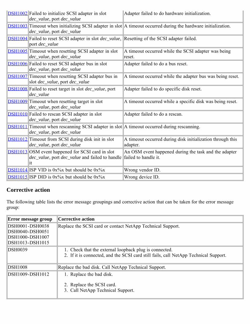
DSH1002 Failed to initialize SCSI adapter in slotdec_value, port dec_value
Adapter failed to do hardware initialization.
DSH1003 Timeout when initializing SCSI adapter in slotdec_value, port dec_value
A timeout occurred during the hardware initialization.
DSH1004 Failed to reset SCSI adapter in slot dec_value,port dec_value
Resetting of the SCSI adapter failed.
DSH1005 Timeout when resetting SCSI adapter in slotdec_value, port dec_value
A timeout occurred while the SCSI adapter was beingreset.
DSH1006 Failed to reset SCSI adapter bus in slotdec_value, port dec_value
Adapter failed to do a bus reset.
DSH1007 Timeout when resetting SCSI adapter bus inslot dec_value, port dec_value
A timeout occurred while the adapter bus was being reset.
DSH1008 Failed to reset target in slot dec_value, portdec_value
Adapter failed to do specific disk reset.
DSH1009 Timeout when resetting target in slotdec_value, port dec_value
A timeout occurred while a specific disk was being reset.
DSH1010 Failed to rescan SCSI adapter in slotdec_value, port dec_value
Adapter failed to do a rescan.
DSH1011 Timeout when rescanning SCSI adapter in slotdec_value, port dec_value
A timeout occurred during rescanning.
DSH1012 Timeout from SCSI during disk init in slotdec_value, port dec_value
A timeout occurred during disk initialization through thisadapter.
DSH1013 OSM event happened for SCSI card in slotdec_value, port dec_value and failed to handleit
An OSM event happened during the task and the adapterfailed to handle it.
DSH1014 ISP VID is 0x%x but should be 0x%x Wrong vendor ID.DSH1015 ISP DID is 0x%x but should be 0x%x Wrong device ID.
Corrective action
The following table lists the error message groupings and corrective action that can be taken for the error messagegroup:
Error message group Corrective actionDSH0001-DSH0038DSH0040-DSH0051DSH1000-DSH1007DSH1013-DSH1015
Replace the SCSI card or contact NetApp Technical Support.
DSH0039 1. Check that the external loopback plug is connected.2. If it is connected, and the SCSI card still fails, call NetApp Technical Support.
DSH1008 Replace the bad disk. Call NetApp Technical Support.DSH1009-DSH1012 1. Replace the bad disk.
2. Replace the SCSI card.3. Call NetApp Technical Support.
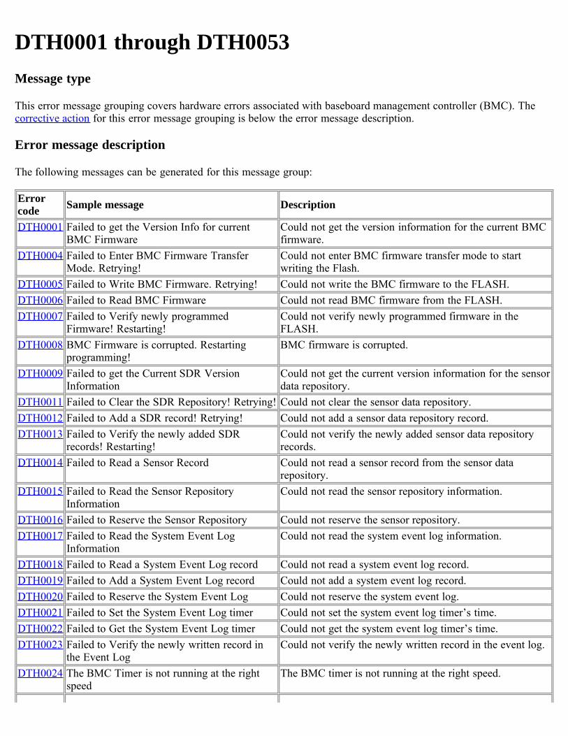
DTH0001 through DTH0053Message type
This error message grouping covers hardware errors associated with baseboard management controller (BMC). Thecorrective action for this error message grouping is below the error message description.
Error message description
The following messages can be generated for this message group:
Errorcode Sample message Description
DTH0001 Failed to get the Version Info for currentBMC Firmware
Could not get the version information for the current BMCfirmware.
DTH0004 Failed to Enter BMC Firmware TransferMode. Retrying!
Could not enter BMC firmware transfer mode to startwriting the Flash.
DTH0005 Failed to Write BMC Firmware. Retrying! Could not write the BMC firmware to the FLASH.DTH0006 Failed to Read BMC Firmware Could not read BMC firmware from the FLASH.DTH0007 Failed to Verify newly programmed
Firmware! Restarting!Could not verify newly programmed firmware in theFLASH.
DTH0008 BMC Firmware is corrupted. Restartingprogramming!
BMC firmware is corrupted.
DTH0009 Failed to get the Current SDR VersionInformation
Could not get the current version information for the sensordata repository.
DTH0011 Failed to Clear the SDR Repository! Retrying! Could not clear the sensor data repository.DTH0012 Failed to Add a SDR record! Retrying! Could not add a sensor data repository record.DTH0013 Failed to Verify the newly added SDR
records! Restarting!Could not verify the newly added sensor data repositoryrecords.
DTH0014 Failed to Read a Sensor Record Could not read a sensor record from the sensor datarepository.
DTH0015 Failed to Read the Sensor RepositoryInformation
Could not read the sensor repository information.
DTH0016 Failed to Reserve the Sensor Repository Could not reserve the sensor repository.DTH0017 Failed to Read the System Event Log
InformationCould not read the system event log information.
DTH0018 Failed to Read a System Event Log record Could not read a system event log record.DTH0019 Failed to Add a System Event Log record Could not add a system event log record.DTH0020 Failed to Reserve the System Event Log Could not reserve the system event log.DTH0021 Failed to Set the System Event Log timer Could not set the system event log timer’s time.DTH0022 Failed to Get the System Event Log timer Could not get the system event log timer’s time.DTH0023 Failed to Verify the newly written record in
the Event LogCould not verify the newly written record in the event log.
DTH0024 The BMC Timer is not running at the rightspeed
The BMC timer is not running at the right speed.
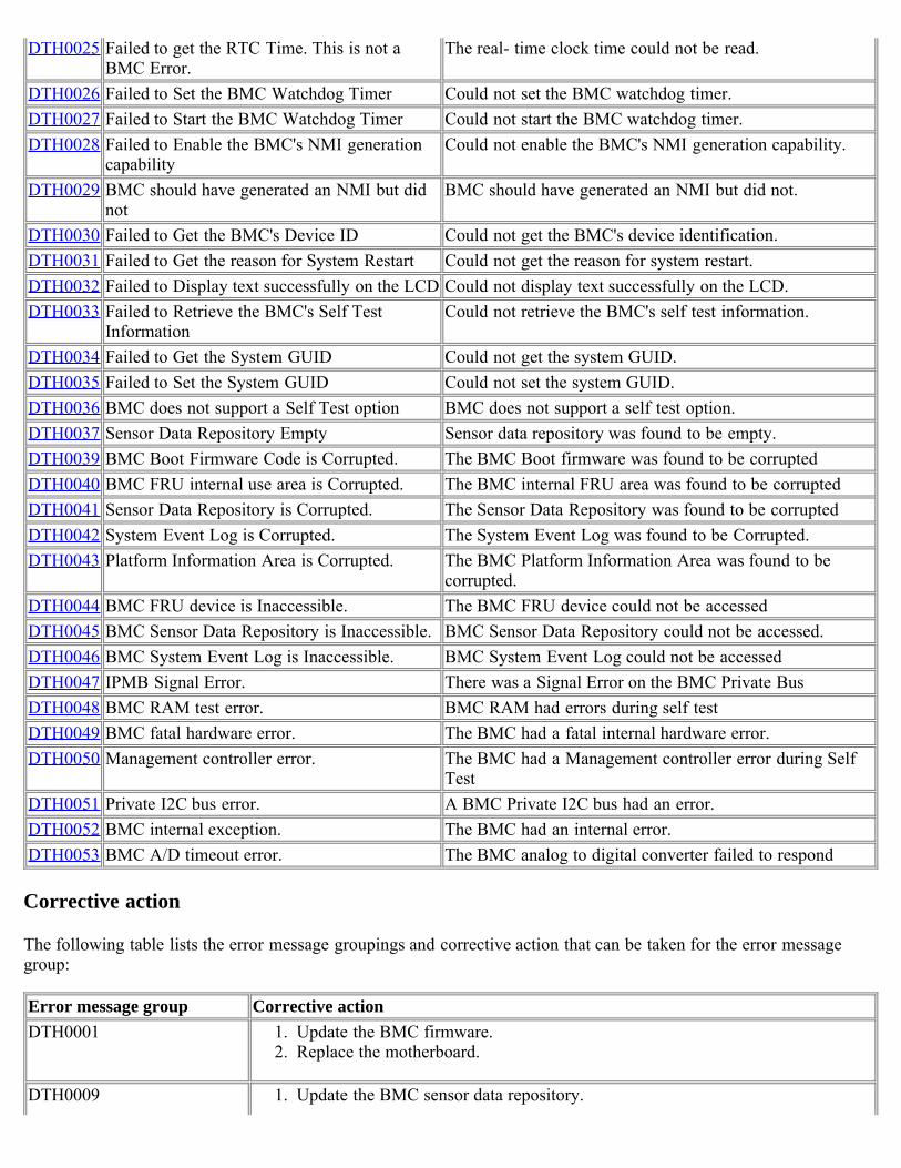
DTH0025 Failed to get the RTC Time. This is not aBMC Error.
The real- time clock time could not be read.
DTH0026 Failed to Set the BMC Watchdog Timer Could not set the BMC watchdog timer.DTH0027 Failed to Start the BMC Watchdog Timer Could not start the BMC watchdog timer.DTH0028 Failed to Enable the BMC's NMI generation
capabilityCould not enable the BMC's NMI generation capability.
DTH0029 BMC should have generated an NMI but didnot
BMC should have generated an NMI but did not.
DTH0030 Failed to Get the BMC's Device ID Could not get the BMC's device identification.DTH0031 Failed to Get the reason for System Restart Could not get the reason for system restart.DTH0032 Failed to Display text successfully on the LCD Could not display text successfully on the LCD.DTH0033 Failed to Retrieve the BMC's Self Test
InformationCould not retrieve the BMC's self test information.
DTH0034 Failed to Get the System GUID Could not get the system GUID.DTH0035 Failed to Set the System GUID Could not set the system GUID.DTH0036 BMC does not support a Self Test option BMC does not support a self test option.DTH0037 Sensor Data Repository Empty Sensor data repository was found to be empty.DTH0039 BMC Boot Firmware Code is Corrupted. The BMC Boot firmware was found to be corruptedDTH0040 BMC FRU internal use area is Corrupted. The BMC internal FRU area was found to be corruptedDTH0041 Sensor Data Repository is Corrupted. The Sensor Data Repository was found to be corruptedDTH0042 System Event Log is Corrupted. The System Event Log was found to be Corrupted.DTH0043 Platform Information Area is Corrupted. The BMC Platform Information Area was found to be
corrupted.DTH0044 BMC FRU device is Inaccessible. The BMC FRU device could not be accessedDTH0045 BMC Sensor Data Repository is Inaccessible. BMC Sensor Data Repository could not be accessed.DTH0046 BMC System Event Log is Inaccessible. BMC System Event Log could not be accessedDTH0047 IPMB Signal Error. There was a Signal Error on the BMC Private BusDTH0048 BMC RAM test error. BMC RAM had errors during self testDTH0049 BMC fatal hardware error. The BMC had a fatal internal hardware error.DTH0050 Management controller error. The BMC had a Management controller error during Self
TestDTH0051 Private I2C bus error. A BMC Private I2C bus had an error.DTH0052 BMC internal exception. The BMC had an internal error.DTH0053 BMC A/D timeout error. The BMC analog to digital converter failed to respond
Corrective action
The following table lists the error message groupings and corrective action that can be taken for the error messagegroup:
Error message group Corrective actionDTH0001 1. Update the BMC firmware.
2. Replace the motherboard.
DTH0009 1. Update the BMC sensor data repository.

2. Replace the motherboard.
DTH0004-DTH0008DTH0011-DTH0053
Replace the motherboard or contact NetApp Technical Support.
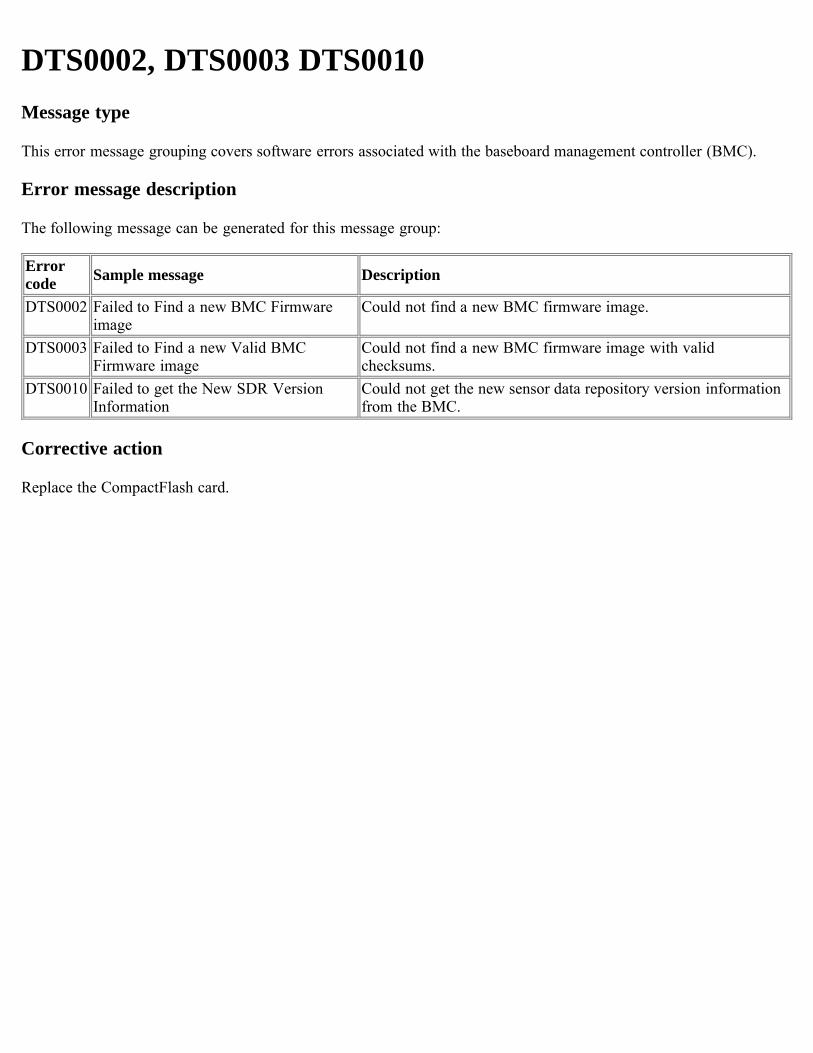
DTS0002, DTS0003 DTS0010Message type
This error message grouping covers software errors associated with the baseboard management controller (BMC).
Error message description
The following message can be generated for this message group:
Errorcode Sample message Description
DTS0002 Failed to Find a new BMC Firmwareimage
Could not find a new BMC firmware image.
DTS0003 Failed to Find a new Valid BMCFirmware image
Could not find a new BMC firmware image with validchecksums.
DTS0010 Failed to get the New SDR VersionInformation
Could not get the new sensor data repository version informationfrom the BMC.
Corrective action
Replace the CompactFlash card.
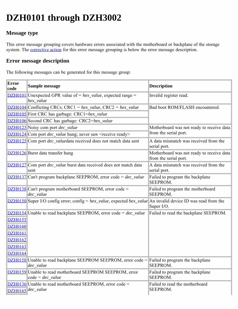
DZH0101 through DZH3002Message type
This error message grouping covers hardware errors associated with the motherboard or backplane of the storagesystem. The corrective action for this error message grouping is below the error message description.
Error message description
The following messages can be generated for this message group:
Errorcode Sample message Description
DZH0101 Unexpected GPR value of = hex_value, expected range =hex_value
Invalid register read.
DZH0104 Conflicting CRCs; CRC1 = hex_value, CRC2 = hex_value Bad boot ROM/FLASH encountered.DZH0105 First CRC has garbage: CRC1=hex_valueDZH0106 Second CRC has garbage: CRC2=hex_valueDZH0123 Noisy com port dec_value Motherboard was not ready to receive data
from the serial port.DZH0124 Com port dec_value hung; never saw <receive ready>DZH0125 Com port dec_valuedata received does not match data sent A data mismatch was received from the
serial port.DZH0126 Burst data transfer hung Motherboard was not ready to receive data
from the serial port.DZH0127 Com port dec_value burst data received does not match data
sentA data mismatch was received from theserial port.
DZH0137 Can't program backplane SEEPROM, error code = dec_value Failed to program the backplaneSEEPROM.
DZH0138 Can't program motherboard SEEPROM, error code =dec_value
Failed to program the motherboardSEEPROM.
DZH0150 Super I/O config error; config = hex_value, expected hex_value An invalid device ID was read from theSuper I/O.
DZH0154 Unable to read backplane SEEPROM, error code = dec_value Failed to read the backplane SEEPROM.DZH0155DZH0160DZH0161DZH0162DZH0163DZH0164DZH0158 Unable to read backplane SEEPROM SEEPROM, error code =
dec_valueFailed to program the backplaneSEEPROM.
DZH0159 Unable to read motherboard SEEPROM SEEPROM, errorcode = dec_value
Failed to program the backplaneSEEPROM.
DZH0136 Unable to read motherboard SEEPROM, error code =dec_value
Failed to read the motherboardSEEPROM.DZH0165
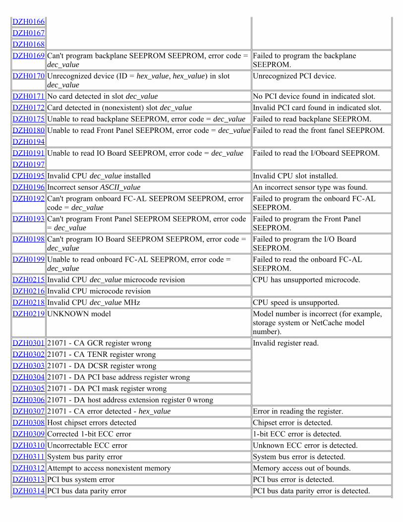
DZH0166DZH0167DZH0168DZH0169 Can't program backplane SEEPROM SEEPROM, error code =
dec_valueFailed to program the backplaneSEEPROM.
DZH0170 Unrecognized device (ID = hex_value, hex_value) in slotdec_value
Unrecognized PCI device.
DZH0171 No card detected in slot dec_value No PCI device found in indicated slot.DZH0172 Card detected in (nonexistent) slot dec_value Invalid PCI card found in indicated slot.DZH0175 Unable to read backplane SEEPROM, error code = dec_value Failed to read backplane SEEPROM.DZH0180 Unable to read Front Panel SEEPROM, error code = dec_value Failed to read the front fanel SEEPROM.DZH0194DZH0191 Unable to read IO Board SEEPROM, error code = dec_value Failed to read the I/Oboard SEEPROM.DZH0197DZH0195 Invalid CPU dec_value installed Invalid CPU slot installed.DZH0196 Incorrect sensor ASCII_value An incorrect sensor type was found.DZH0192 Can't program onboard FC-AL SEEPROM SEEPROM, error
code = dec_valueFailed to program the onboard FC-ALSEEPROM.
DZH0193 Can't program Front Panel SEEPROM SEEPROM, error code= dec_value
Failed to program the Front PanelSEEPROM.
DZH0198 Can't program IO Board SEEPROM SEEPROM, error code =dec_value
Failed to program the I/O BoardSEEPROM.
DZH0199 Unable to read onboard FC-AL SEEPROM, error code =dec_value
Failed to read the onboard FC-ALSEEPROM.
DZH0215 Invalid CPU dec_value microcode revision CPU has unsupported microcode.DZH0216 Invalid CPU microcode revisionDZH0218 Invalid CPU dec_value MHz CPU speed is unsupported.DZH0219 UNKNOWN model Model number is incorrect (for example,
storage system or NetCache modelnumber).
DZH0301 21071 - CA GCR register wrong Invalid register read.DZH0302 21071 - CA TENR register wrongDZH0303 21071 - DA DCSR register wrongDZH0304 21071 - DA PCI base address register wrongDZH0305 21071 - DA PCI mask register wrongDZH0306 21071 - DA host address extension register 0 wrongDZH0307 21071 - CA error detected - hex_value Error in reading the register.DZH0308 Host chipset errors detected Chipset error is detected.DZH0309 Corrected 1-bit ECC error 1-bit ECC error is detected.DZH0310 Uncorrectable ECC error Unknown ECC error is detected.DZH0311 System bus parity error System bus error is detected.DZH0312 Attempt to access nonexistent memory Memory access out of bounds.DZH0313 PCI bus system error PCI bus error is detected.DZH0314 PCI bus data parity error PCI bus data parity error is detected.
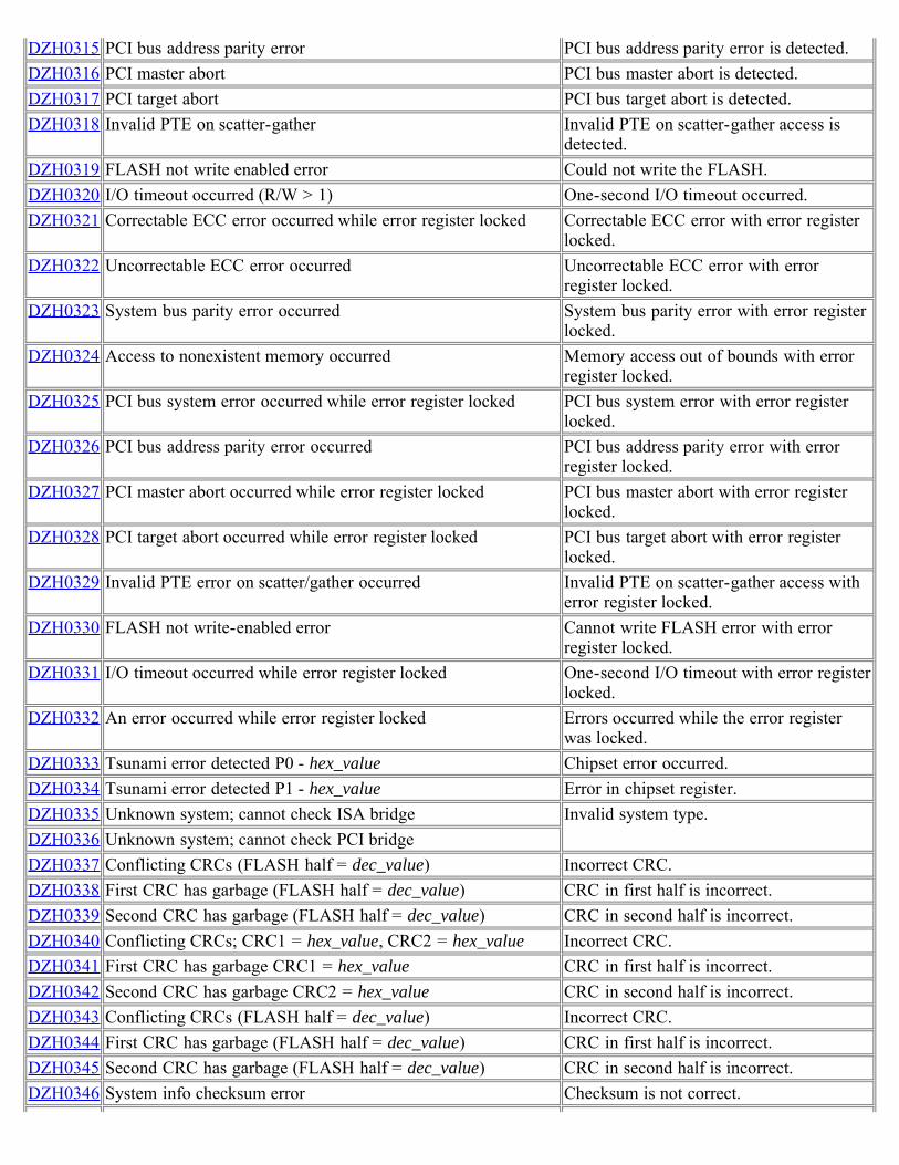
DZH0315 PCI bus address parity error PCI bus address parity error is detected.DZH0316 PCI master abort PCI bus master abort is detected.DZH0317 PCI target abort PCI bus target abort is detected.DZH0318 Invalid PTE on scatter-gather Invalid PTE on scatter-gather access is
detected.DZH0319 FLASH not write enabled error Could not write the FLASH.DZH0320 I/O timeout occurred (R/W > 1) One-second I/O timeout occurred.DZH0321 Correctable ECC error occurred while error register locked Correctable ECC error with error register
locked.DZH0322 Uncorrectable ECC error occurred Uncorrectable ECC error with error
register locked.DZH0323 System bus parity error occurred System bus parity error with error register
locked.DZH0324 Access to nonexistent memory occurred Memory access out of bounds with error
register locked.DZH0325 PCI bus system error occurred while error register locked PCI bus system error with error register
locked.DZH0326 PCI bus address parity error occurred PCI bus address parity error with error
register locked.DZH0327 PCI master abort occurred while error register locked PCI bus master abort with error register
locked.DZH0328 PCI target abort occurred while error register locked PCI bus target abort with error register
locked.DZH0329 Invalid PTE error on scatter/gather occurred Invalid PTE on scatter-gather access with
error register locked.DZH0330 FLASH not write-enabled error Cannot write FLASH error with error
register locked.DZH0331 I/O timeout occurred while error register locked One-second I/O timeout with error register
locked.DZH0332 An error occurred while error register locked Errors occurred while the error register
was locked.DZH0333 Tsunami error detected P0 - hex_value Chipset error occurred.DZH0334 Tsunami error detected P1 - hex_value Error in chipset register.DZH0335 Unknown system; cannot check ISA bridge Invalid system type.DZH0336 Unknown system; cannot check PCI bridgeDZH0337 Conflicting CRCs (FLASH half = dec_value) Incorrect CRC.DZH0338 First CRC has garbage (FLASH half = dec_value) CRC in first half is incorrect.DZH0339 Second CRC has garbage (FLASH half = dec_value) CRC in second half is incorrect.DZH0340 Conflicting CRCs; CRC1 = hex_value, CRC2 = hex_value Incorrect CRC.DZH0341 First CRC has garbage CRC1 = hex_value CRC in first half is incorrect.DZH0342 Second CRC has garbage CRC2 = hex_value CRC in second half is incorrect.DZH0343 Conflicting CRCs (FLASH half = dec_value) Incorrect CRC.DZH0344 First CRC has garbage (FLASH half = dec_value) CRC in first half is incorrect.DZH0345 Second CRC has garbage (FLASH half = dec_value) CRC in second half is incorrect.DZH0346 System info checksum error Checksum is not correct.
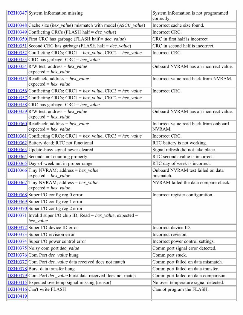
DZH0347 System information missing System information is not programmedcorrectly.
DZH0348 Cache size (hex_value) mismatch with model (ASCII_value) Incorrect cache size found.DZH0349 Conflicting CRCs (FLASH half = dec_value) Incorrect CRC.DZH0350 First CRC has garbage (FLASH half = dec_value) CRC in first half is incorrect.DZH0351 Second CRC has garbage (FLASH half = dec_value) CRC in second half is incorrect.DZH0352 Conflicting CRCs; CRC1 = hex_value, CRC2 = hex_value Incorrect CRC.DZH0353 CRC has garbage; CRC = hex_valueDZH0354 R/W test, address = hex_value
expected = hex_valueOnboard NVRAM has an incorrect value.
DZH0355 Readback, address = hex_valueexpected = hex_value
Incorrect value read back from NVRAM.
DZH0356 Conflicting CRCs; CRC1 = hex_value, CRC3 = hex_value Incorrect CRC.DZH0357 Conflicting CRCs; CRC1 = hex_value, CRC2 = hex_valueDZH0358 CRC has garbage; CRC = hex_valueDZH0359 R/W test; address = hex_value
expected = hex_valueOnboard NVRAM has an incorrect value.
DZH0360 Readback; address = hex_valueexpected = hex_value
Incorrect value read back from onboardNVRAM.
DZH0361 Conflicting CRCs; CRC1 = hex_value, CRC3 = hex_value Incorrect CRC.DZH0362 Battery dead; RTC not functional RTC battery is not working.DZH0363 Update-busy signal never cleared Signal refresh did not take place.DZH0364 Seconds not counting properly RTC seconds value is incorrect.DZH0365 Day-of-week not in proper range RTC day of week is incorrect.DZH0366 Tiny NVRAM; address = hex_value
expected = hex_valueOnboard NVRAM test failed on datamismatch.
DZH0367 Tiny NVRAM; address = hex_valueexpected = hex_value
NVRAM failed the data compare check.
DZH0368 Super I/O config reg 0 error Incorrect register configuration.DZH0369 Super I/O config reg 1 errorDZH0370 Super I/O config reg 2 errorDZH0371 Invalid super I/O chip ID; Read = hex_value, expected =
hex_valueDZH0372 Super I/O device ID error Incorrect device ID.DZH0373 Super I/O revision error Incorrect revision.DZH0374 Super I/O power control error Incorrect power control settings.DZH0375 Noisy com port dec_value Comm port signal error detected.DZH0376 Com Port dec_value hung Comm port stuck.DZH0377 Com Port dec_value data received does not match Comm port failed on data mismatch.DZH0378 Burst data transfer hung Comm port failed on data transfer.DZH0379 Com Port dec_value burst data received does not match Comm port failed on data comparison.DZH0415 Expected overtemp signal missing (sensor) No over-temperature signal detected.DZH0416 Can't write FLASH Cannot program the FLASH.DZH0419
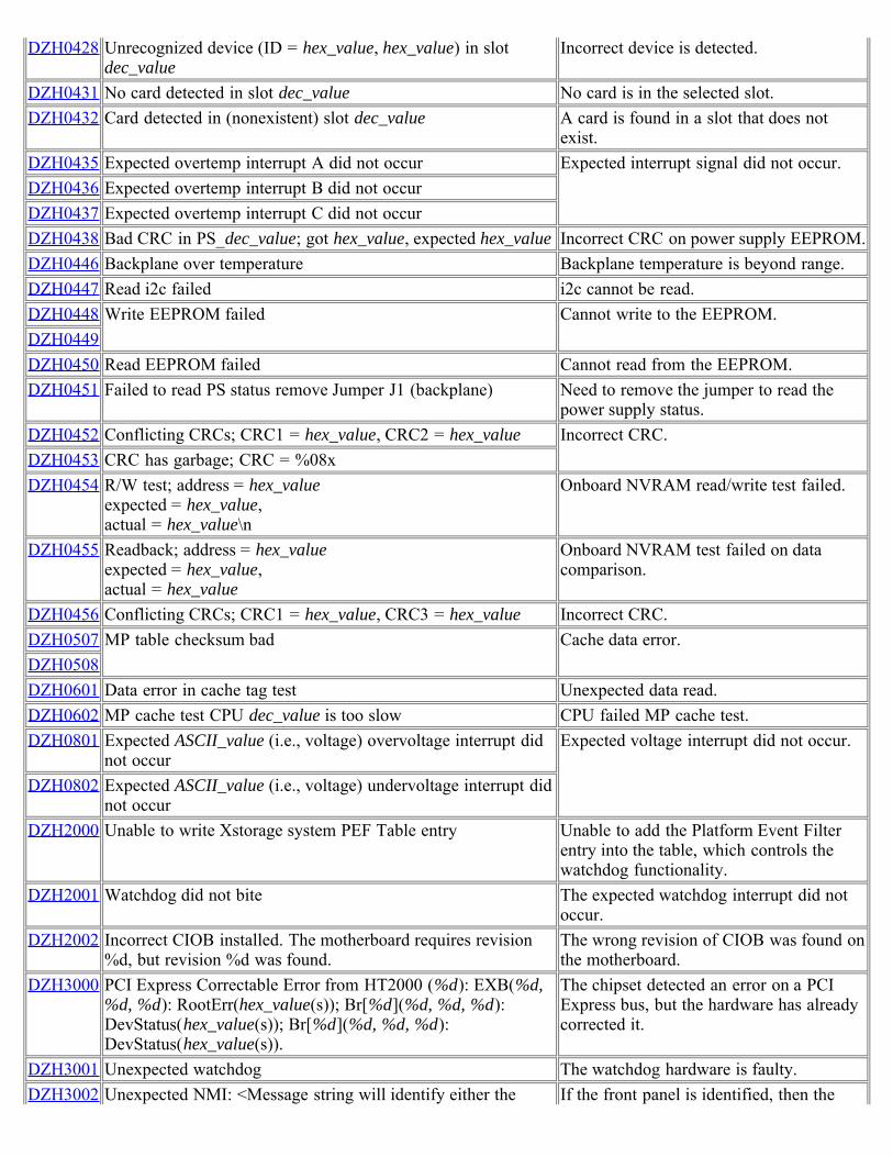
DZH0428 Unrecognized device (ID = hex_value, hex_value) in slotdec_value
Incorrect device is detected.
DZH0431 No card detected in slot dec_value No card is in the selected slot.DZH0432 Card detected in (nonexistent) slot dec_value A card is found in a slot that does not
exist.DZH0435 Expected overtemp interrupt A did not occur Expected interrupt signal did not occur.DZH0436 Expected overtemp interrupt B did not occurDZH0437 Expected overtemp interrupt C did not occurDZH0438 Bad CRC in PS_dec_value; got hex_value, expected hex_value Incorrect CRC on power supply EEPROM.DZH0446 Backplane over temperature Backplane temperature is beyond range.DZH0447 Read i2c failed i2c cannot be read.DZH0448 Write EEPROM failed Cannot write to the EEPROM.DZH0449DZH0450 Read EEPROM failed Cannot read from the EEPROM.DZH0451 Failed to read PS status remove Jumper J1 (backplane) Need to remove the jumper to read the
power supply status.DZH0452 Conflicting CRCs; CRC1 = hex_value, CRC2 = hex_value Incorrect CRC.DZH0453 CRC has garbage; CRC = %08xDZH0454 R/W test; address = hex_value
expected = hex_value,actual = hex_value\n
Onboard NVRAM read/write test failed.
DZH0455 Readback; address = hex_valueexpected = hex_value,actual = hex_value
Onboard NVRAM test failed on datacomparison.
DZH0456 Conflicting CRCs; CRC1 = hex_value, CRC3 = hex_value Incorrect CRC.DZH0507 MP table checksum bad Cache data error.DZH0508DZH0601 Data error in cache tag test Unexpected data read.DZH0602 MP cache test CPU dec_value is too slow CPU failed MP cache test.DZH0801 Expected ASCII_value (i.e., voltage) overvoltage interrupt did
not occurExpected voltage interrupt did not occur.
DZH0802 Expected ASCII_value (i.e., voltage) undervoltage interrupt didnot occur
DZH2000 Unable to write Xstorage system PEF Table entry Unable to add the Platform Event Filterentry into the table, which controls thewatchdog functionality.
DZH2001 Watchdog did not bite The expected watchdog interrupt did notoccur.
DZH2002 Incorrect CIOB installed. The motherboard requires revision%d, but revision %d was found.
The wrong revision of CIOB was found onthe motherboard.
DZH3000 PCI Express Correctable Error from HT2000 (%d): EXB(%d,%d, %d): RootErr(hex_value(s)); Br[%d](%d, %d, %d):DevStatus(hex_value(s)); Br[%d](%d, %d, %d):DevStatus(hex_value(s)).
The chipset detected an error on a PCIExpress bus, but the hardware has alreadycorrected it.
DZH3001 Unexpected watchdog The watchdog hardware is faulty.DZH3002 Unexpected NMI: <Message string will identify either the If the front panel is identified, then the
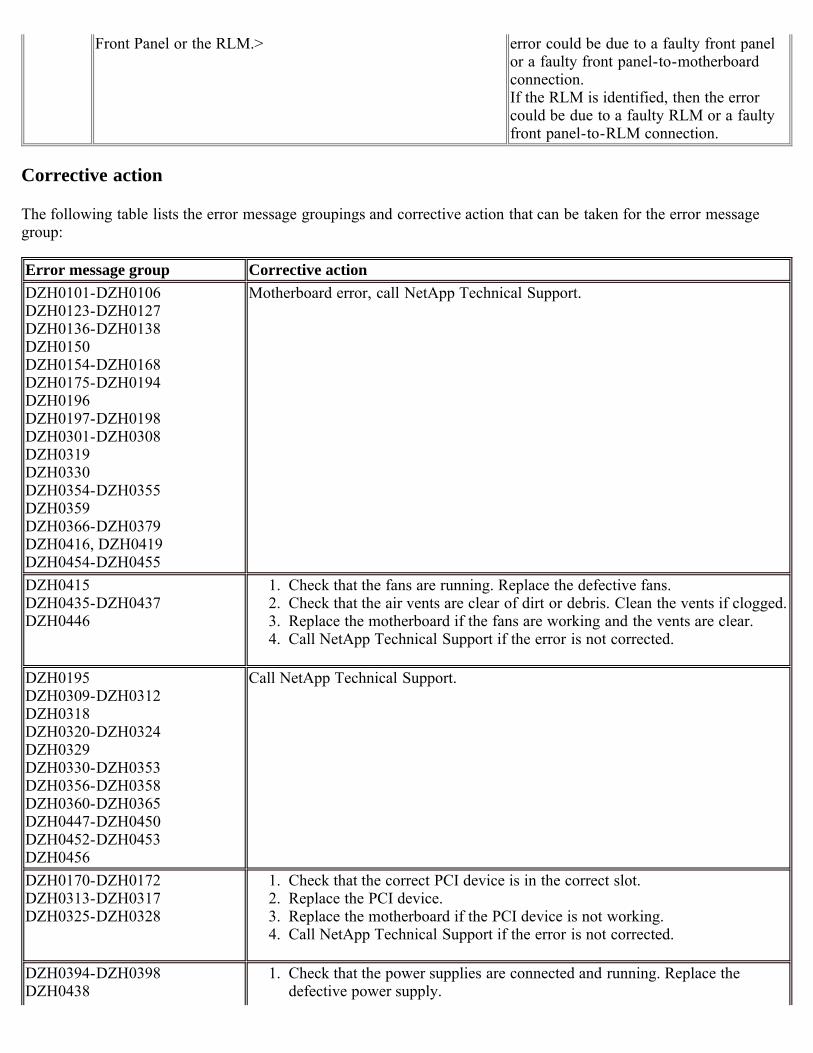
Front Panel or the RLM.> error could be due to a faulty front panelor a faulty front panel-to-motherboardconnection.If the RLM is identified, then the errorcould be due to a faulty RLM or a faultyfront panel-to-RLM connection.
Corrective action
The following table lists the error message groupings and corrective action that can be taken for the error messagegroup:
Error message group Corrective actionDZH0101-DZH0106DZH0123-DZH0127DZH0136-DZH0138DZH0150DZH0154-DZH0168DZH0175-DZH0194DZH0196DZH0197-DZH0198DZH0301-DZH0308DZH0319DZH0330DZH0354-DZH0355DZH0359DZH0366-DZH0379DZH0416, DZH0419DZH0454-DZH0455
Motherboard error, call NetApp Technical Support.
DZH0415DZH0435-DZH0437DZH0446
1. Check that the fans are running. Replace the defective fans.2. Check that the air vents are clear of dirt or debris. Clean the vents if clogged.3. Replace the motherboard if the fans are working and the vents are clear.4. Call NetApp Technical Support if the error is not corrected.
DZH0195DZH0309-DZH0312DZH0318DZH0320-DZH0324DZH0329DZH0330-DZH0353DZH0356-DZH0358DZH0360-DZH0365DZH0447-DZH0450DZH0452-DZH0453DZH0456
Call NetApp Technical Support.
DZH0170-DZH0172DZH0313-DZH0317DZH0325-DZH0328
1. Check that the correct PCI device is in the correct slot.2. Replace the PCI device.3. Replace the motherboard if the PCI device is not working.4. Call NetApp Technical Support if the error is not corrected.
DZH0394-DZH0398DZH0438
1. Check that the power supplies are connected and running. Replace thedefective power supply.
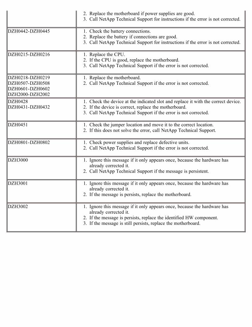
2. Replace the motherboard if power supplies are good.3. Call NetApp Technical Support for instructions if the error is not corrected.
DZH0442-DZH0445 1. Check the battery connections.2. Replace the battery if connections are good.3. Call NetApp Technical Support for instructions if the error is not corrected.
DZH0215-DZH0216 1. Replace the CPU.2. If the CPU is good, replace the motherboard.3. Call NetApp Technical Support if the error is not corrected.
DZH0218-DZH0219 DZH0507-DZH0508DZH0601-DZH0602DZH2000-DZH2002
1. Replace the motherboard.2. Call NetApp Technical Support if the error is not corrected.
DZH0428DZH0431-DZH0432
1. Check the device at the indicated slot and replace it with the correct device.2. If the device is correct, replace the motherboard.3. Call NetApp Technical Support if the error is not corrected.
DZH0451 1. Check the jumper location and move it to the correct location.2. If this does not solve the error, call NetApp Technical Support.
DZH0801-DZH0802 1. Check power supplies and replace defective units.2. Call NetApp Technical Support if the error is not corrected.
DZH3000 1. Ignore this message if it only appears once, because the hardware hasalready corrected it.
2. Call NetApp Technical Support if the message is persistent.
DZH3001 1. Ignore this message if it only appears once, because the hardware hasalready corrected it.
2. If the message is persists, replace the motherboard.
DZH3002 1. Ignore this message if it only appears once, because the hardware hasalready corrected it.
2. If the message is persists, replace the identified HW component.3. If the message is still persists, replace the motherboard.
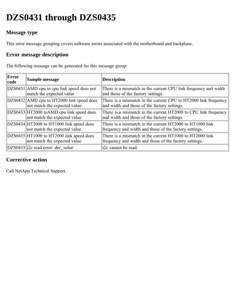
DZS0431 through DZS0435Message type
This error message grouping covers software errors associated with the motherboard and backplane.
Error message description
The following message can be generated for this message group:
Errorcode Sample message Description
DZS0431 AMD cpu to cpu link speed does notmatch the expected value
There is a mismatch in the current CPU link frequency and widthand those of the factory settings.
DZS0432 AMD cpu to HT2000 link speed doesnot match the expected value
There is a mismatch in the current CPU to HT2000 link frequencyand width and those of the factory settings.
DZS0433 HT2000 toAMD cpu link speed doesnot match the expected value
There is a mismatch in the current HT2000 to CPU link frequencyand width and those of the factory settings.
DZS0434 HT2000 to HT1000 link speed doesnot match the expected value
There is a mismatch in the current HT2000 to HT1000 linkfrequency and width and those of the factory settings.
DZS0435 HT1000 to HT2000 link speed doesnot match the expected value
There is a mismatch in the current HT1000 to HT2000 linkfrequency and width and those of the factory settings.
DZS0435 i2c read error: dec_value i2c cannot be read.
Corrective action
Call NetApp Technical Support.
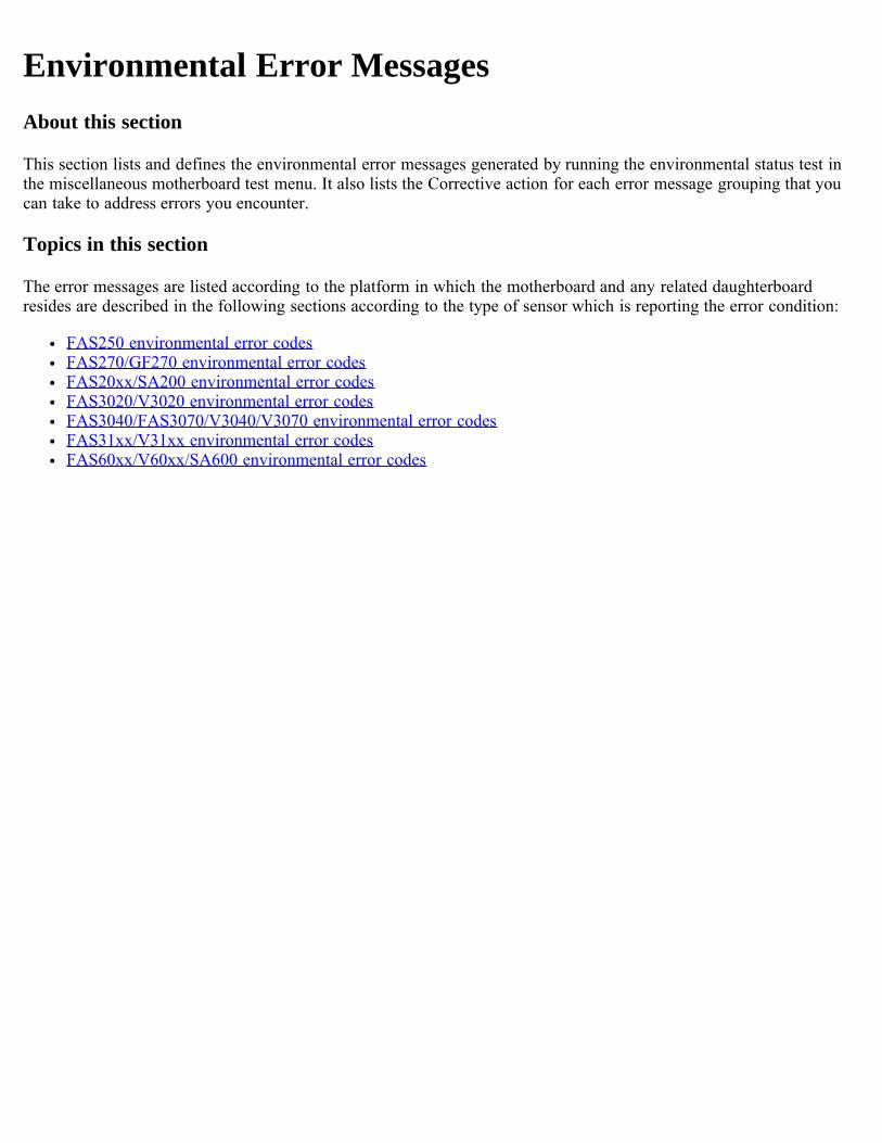
Environmental Error MessagesAbout this section
This section lists and defines the environmental error messages generated by running the environmental status test inthe miscellaneous motherboard test menu. It also lists the Corrective action for each error message grouping that youcan take to address errors you encounter.
Topics in this section
The error messages are listed according to the platform in which the motherboard and any related daughterboardresides are described in the following sections according to the type of sensor which is reporting the error condition:
FAS250 environmental error codesFAS270/GF270 environmental error codesFAS20xx/SA200 environmental error codesFAS3020/V3020 environmental error codesFAS3040/FAS3070/V3040/V3070 environmental error codesFAS31xx/V31xx environmental error codesFAS60xx/V60xx/SA600 environmental error codes
FAS250 environmental error codesMessage type
The FAS250 environmental error messages are tabulated according to the sensors that generate them:
Temperature sensorsVoltage power sensorsChassis and CPU fan sensorsPower supply sensors
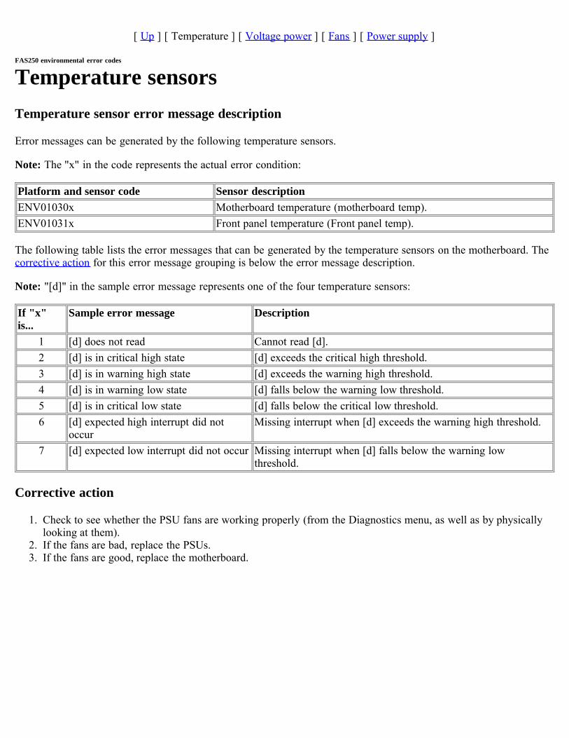
[ Up ] [ Temperature ] [ Voltage power ] [ Fans ] [ Power supply ]
FAS250 environmental error codes
Temperature sensorsTemperature sensor error message description
Error messages can be generated by the following temperature sensors.
Note: The "x" in the code represents the actual error condition:
Platform and sensor code Sensor descriptionENV01030x Motherboard temperature (motherboard temp).ENV01031x Front panel temperature (Front panel temp).
The following table lists the error messages that can be generated by the temperature sensors on the motherboard. Thecorrective action for this error message grouping is below the error message description.
Note: "[d]" in the sample error message represents one of the four temperature sensors:
If "x"is...
Sample error message Description
1 [d] does not read Cannot read [d].2 [d] is in critical high state [d] exceeds the critical high threshold.3 [d] is in warning high state [d] exceeds the warning high threshold.4 [d] is in warning low state [d] falls below the warning low threshold.5 [d] is in critical low state [d] falls below the critical low threshold.6 [d] expected high interrupt did not
occurMissing interrupt when [d] exceeds the warning high threshold.
7 [d] expected low interrupt did not occur Missing interrupt when [d] falls below the warning lowthreshold.
Corrective action
1. Check to see whether the PSU fans are working properly (from the Diagnostics menu, as well as by physicallylooking at them).
2. If the fans are bad, replace the PSUs.3. If the fans are good, replace the motherboard.
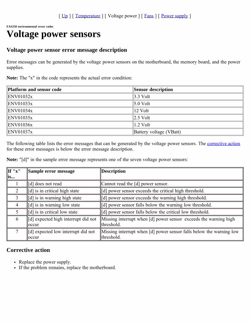
[ Up ] [ Temperature ] [ Voltage power ] [ Fans ] [ Power supply ]
FAS250 environmental error codes
Voltage power sensorsVoltage power sensor error message description
Error messages can be generated by the voltage power sensors on the motherboard, the memory board, and the powersupplies.
Note: The "x" in the code represents the actual error condition:
Platform and sensor code Sensor descriptionENV01032x 3.3 VoltENV01033x 5.0 VoltENV01034x 12 VoltENV01035x 2.5 VoltENV01036x 1.2 VoltENV01037x Battery voltage (VBatt)
The following table lists the error messages that can be generated by the voltage power sensors. The corrective actionfor these error messages is below the error message description.
Note: "[d]" in the sample error message represents one of the seven voltage power sensors:
If "x"is...
Sample error message Description
1 [d] does not read Cannot read the [d] power sensor.2 [d] is in critical high state [d] power sensor exceeds the critical high threshold.3 [d] is in warning high state [d] power sensor exceeds the warning high threshold.4 [d] is in warning low state [d] power sensor falls below the warning low threshold.5 [d] is in critical low state [d] power sensor falls below the critical low threshold.6 [d] expected high interrupt did not
occurMissing interrupt when [d] power sensor exceeds the warning highthreshold.
7 [d] expected low interrupt did notoccur
Missing interrupt when [d] power sensor falls below the warning lowthreshold.
Corrective action
Replace the power supply. If the problem remains, replace the motherboard.
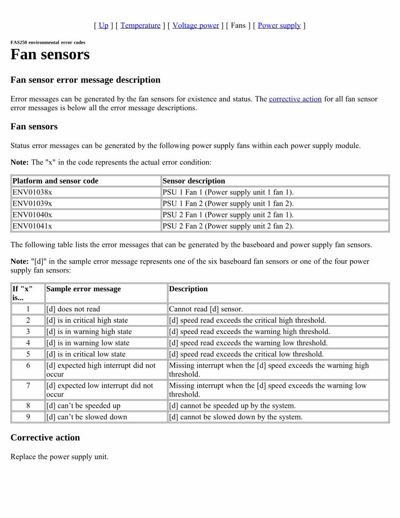
[ Up ] [ Temperature ] [ Voltage power ] [ Fans ] [ Power supply ]
FAS250 environmental error codes
Fan sensorsFan sensor error message description
Error messages can be generated by the fan sensors for existence and status. The corrective action for all fan sensorerror messages is below all the error message descriptions.
Fan sensors
Status error messages can be generated by the following power supply fans within each power supply module.
Note: The "x" in the code represents the actual error condition:
Platform and sensor code Sensor descriptionENV01038x PSU 1 Fan 1 (Power supply unit 1 fan 1).ENV01039x PSU 1 Fan 2 (Power supply unit 1 fan 2).ENV01040x PSU 2 Fan 1 (Power supply unit 2 fan 1).ENV01041x PSU 2 Fan 2 (Power supply unit 2 fan 2).
The following table lists the error messages that can be generated by the baseboard and power supply fan sensors.
Note: "[d]" in the sample error message represents one of the six baseboard fan sensors or one of the four powersupply fan sensors:
If "x"is...
Sample error message Description
1 [d] does not read Cannot read [d] sensor.2 [d] is in critical high state [d] speed read exceeds the critical high threshold.3 [d] is in warning high state [d] speed read exceeds the warning high threshold.4 [d] is in warning low state [d] speed read exceeds the warning low threshold.5 [d] is in critical low state [d] speed read exceeds the critical low threshold.6 [d] expected high interrupt did not
occurMissing interrupt when the [d] speed exceeds the warning highthreshold.
7 [d] expected low interrupt did notoccur
Missing interrupt when the [d] speed exceeds the warning lowthreshold.
8 [d] can’t be speeded up [d] cannot be speeded up by the system.9 [d] can’t be slowed down [d] cannot be slowed down by the system.
Corrective action
Replace the power supply unit.
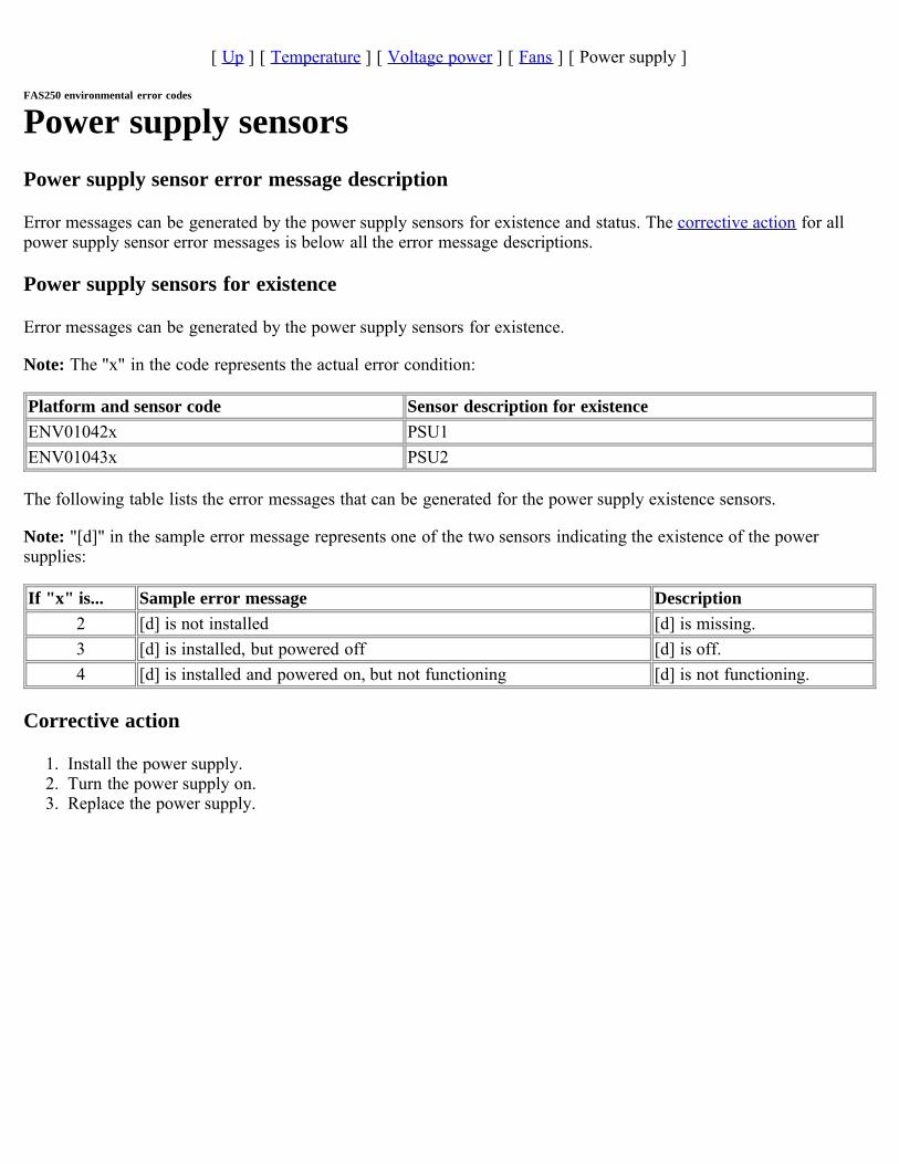
[ Up ] [ Temperature ] [ Voltage power ] [ Fans ] [ Power supply ]
FAS250 environmental error codes
Power supply sensorsPower supply sensor error message description
Error messages can be generated by the power supply sensors for existence and status. The corrective action for allpower supply sensor error messages is below all the error message descriptions.
Power supply sensors for existence
Error messages can be generated by the power supply sensors for existence.
Note: The "x" in the code represents the actual error condition:
Platform and sensor code Sensor description for existenceENV01042x PSU1ENV01043x PSU2
The following table lists the error messages that can be generated for the power supply existence sensors.
Note: "[d]" in the sample error message represents one of the two sensors indicating the existence of the powersupplies:
If "x" is... Sample error message Description2 [d] is not installed [d] is missing.3 [d] is installed, but powered off [d] is off.4 [d] is installed and powered on, but not functioning [d] is not functioning.
Corrective action
1. Install the power supply.2. Turn the power supply on. 3. Replace the power supply.
FAS270/GF270 environmental error codesMessage type
The FAS270/GF270 environmental error messages are tabulated according to the sensors that generate them:
Temperature sensorsVoltage power sensorsChassis and CPU fan sensorsPower supply sensors

[ Up ] [ Temperature ] [ Voltage power ] [ Fans ] [ Power supply ]
FAS270/GF270 environmental error codes
Temperature sensorsTemperature sensor error message description
Error messages can be generated by the following temperature sensors.
Note: The "x" in the code represents the actual error condition:
Platform and sensor code Sensor descriptionENV01060x Motherboard temperature (motherboard temp).ENV01061x Front panel temperature (Front panel temp).
The following table lists the error messages that can be generated by the temperature sensors on the motherboard. Thecorrective action for this error message grouping is below the error message description.
Note: "[d]" in the sample error message represents one of the four temperature sensors:
If "x"is...
Sample error message Description
1 [d] does not read Cannot read [d].2 [d] is in critical high state [d] exceeds the critical high threshold.3 [d] is in warning high state [d] exceeds the warning high threshold.4 [d] is in warning low state [d] falls below the warning low threshold.5 [d] is in critical low state [d] falls below the critical low threshold.6 [d] expected high interrupt did not
occurMissing interrupt when [d] exceeds the warning high threshold.
7 [d] expected low interrupt did not occur Missing interrupt when [d] falls below the warning lowthreshold.
Corrective action
1. Check to see whether the PSU fans are working properly (from the Diagnostics menu, as well as by physicallylooking at them).
2. If the fans are bad, replace the PSUs.3. If the fans are good, replace the motherboard.
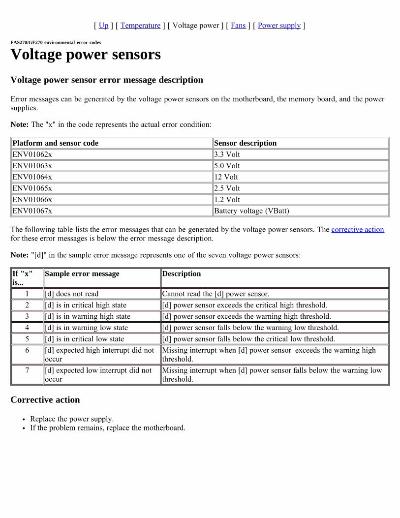
[ Up ] [ Temperature ] [ Voltage power ] [ Fans ] [ Power supply ]
FAS270/GF270 environmental error codes
Voltage power sensorsVoltage power sensor error message description
Error messages can be generated by the voltage power sensors on the motherboard, the memory board, and the powersupplies.
Note: The "x" in the code represents the actual error condition:
Platform and sensor code Sensor descriptionENV01062x 3.3 VoltENV01063x 5.0 VoltENV01064x 12 VoltENV01065x 2.5 VoltENV01066x 1.2 VoltENV01067x Battery voltage (VBatt)
The following table lists the error messages that can be generated by the voltage power sensors. The corrective actionfor these error messages is below the error message description.
Note: "[d]" in the sample error message represents one of the seven voltage power sensors:
If "x"is...
Sample error message Description
1 [d] does not read Cannot read the [d] power sensor.2 [d] is in critical high state [d] power sensor exceeds the critical high threshold.3 [d] is in warning high state [d] power sensor exceeds the warning high threshold.4 [d] is in warning low state [d] power sensor falls below the warning low threshold.5 [d] is in critical low state [d] power sensor falls below the critical low threshold.6 [d] expected high interrupt did not
occurMissing interrupt when [d] power sensor exceeds the warning highthreshold.
7 [d] expected low interrupt did notoccur
Missing interrupt when [d] power sensor falls below the warning lowthreshold.
Corrective action
Replace the power supply. If the problem remains, replace the motherboard.

[ Up ] [ Temperature ] [ Voltage power ] [ Fans ] [ Power supply ]
FAS270/GF270 environmental error codes
Fan sensorsFan sensor error message description
Error messages can be generated by the fan sensors for existence and status. The corrective action for all fan sensorerror messages is below all the error message descriptions.
Fan sensors
Status error messages can be generated by the following power supply fans within each power supply module.
Note: The "x" in the code represents the actual error condition:
Platform and sensor code Sensor descriptionENV01068x PSU 1 Fan 1 (Power supply unit 1 fan 1).ENV01069x PSU 1 Fan 2 (Power supply unit 1 fan 2).ENV01070x PSU 2 Fan 1 (Power supply unit 2 fan 1).ENV01071x PSU 2 Fan 2 (Power supply unit 2 fan 2).
The following table lists the error messages that can be generated by the baseboard and power supply fan sensors.
Note: "[d]" in the sample error message represents one of the six baseboard fan sensors or one of the four powersupply fan sensors:
If "x"is...
Sample error message Description
1 [d] does not read Cannot read [d] sensor.2 [d] is in critical high state [d] speed read exceeds the critical high threshold.3 [d] is in warning high state [d] speed read exceeds the warning high threshold.4 [d] is in warning low state [d] speed read exceeds the warning low threshold.5 [d] is in critical low state [d] speed read exceeds the critical low threshold.6 [d] expected high interrupt did not
occurMissing interrupt when the [d] speed exceeds the warning highthreshold.
7 [d] expected low interrupt did notoccur
Missing interrupt when the [d] speed exceeds the warning lowthreshold.
8 [d] can’t be speeded up [d] cannot be speeded up by the system.9 [d] can’t be slowed down [d] cannot be slowed down by the system.
Corrective action
Replace the power supply unit.

[ Up ] [ Temperature ] [ Voltage power ] [ Fans ] [ Power supply ]
FAS270/GF270 environmental error codes
Power supply sensorsPower supply sensor error message description
Error messages can be generated by the power supply sensors for existence and status. The corrective action for allpower supply sensor error messages is below all the error message descriptions.
Power supply sensors for existence
Error messages can be generated by the power supply sensors for existence.
Note: The "x" in the code represents the actual error condition:
Platform and sensor code Sensor description for existenceENV01072x PSU1ENV01073x PSU2
The following table lists the error messages that can be generated for the power supply existence sensors.
Note: "[d]" in the sample error message represents one of the two sensors indicating the existence of the powersupplies:
If "x" is... Sample error message Description2 [d] is not installed [d] is missing.3 [d] is installed, but powered off [d] is off.4 [d] is installed and powered on, but not functioning [d] is not functioning.
Corrective action
1. Install the power supply.2. Turn the power supply on.3. Replace the power supply.
FAS20xx/SA200 environmental error codesMessage type
The FAS20xx/SA200 environmental error messages are tabulated according to the sensors that generate them:
Temperature sensorsVoltage sensorsCurrent sensorsOther battery sensorsFansPower status sensors
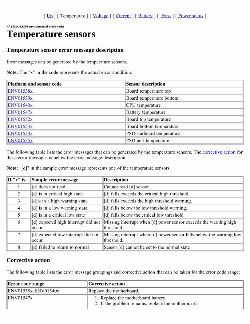
[ Up ] [ Temperature ] [ Voltage ] [ Current ] [ Battery ] [ Fans ] [ Power status ]
FAS20xx/SA200 environmental error codes
Temperature sensorsTemperature sensor error message description
Error messages can be generated by the temperature sensors.
Note: The "x" in the code represents the actual error condition:
Platform and sensor code Sensor descriptionENV01538x Board temperature topENV01539x Board temperature bottomENV01540x CPU temperatureENV01547x Battery temperatureENV01552x Board top temperatureENV01553x Board bottom temperatureENV01554x PSU starboard temperatureENV01555x PSU port temperature
The following table lists the error messages that can be generated by the temperature sensors. The corrective action forthese error messages is below the error message description.
Note: "[d]" in the sample error message represents one of the temperature sensors:
If "x" is... Sample error message Description1 [d] does not read Cannot read [d] sensor.2 [d] is in critical high state [d] falls exceeds the critical high threshold.3 [d]is in a high warning state [d] falls exceeds the high threshold warning.4 [d] is in a low warning state [d] falls below the low threshold warning.5 [d] is in a critical low state [d] falls below the critical low threshold.6 [d] expected high interrupt did not
occurMissing interrupt when [d] power sensor exceeds the warning highthreshold.
7 [d] expected low interrupt did notoccur
Missing interrupt when [d] power sensor falls below the warning lowthreshold.
8 [d] failed to return to normal Sensor [d] cannot be set to the normal state
Corrective action
The following table lists the error message groupings and corrective action that can be taken for the error code range:
Error code range Corrective actionENV01538x-ENV01540x Replace the motherboard.ENV01547x 1. Replace the motherboard battery.
2. If the problem remains, replace the motherboard.

ENV01552x Replace the top PCM motherboard in chassis.ENV01553x Replace the bottom PCM motherboard in chassis.ENV01554x Replace PSU 2.ENV01555x Replace PSU 1.
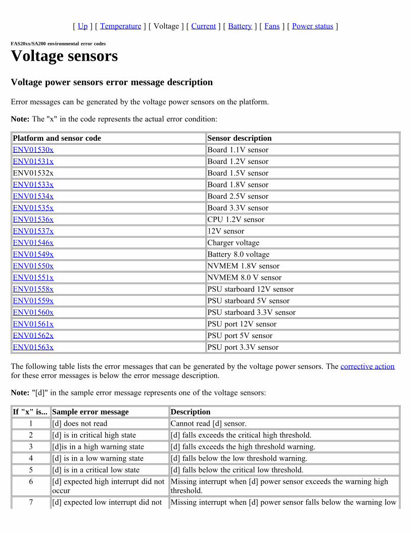
[ Up ] [ Temperature ] [ Voltage ] [ Current ] [ Battery ] [ Fans ] [ Power status ]
FAS20xx/SA200 environmental error codes
Voltage sensorsVoltage power sensors error message description
Error messages can be generated by the voltage power sensors on the platform.
Note: The "x" in the code represents the actual error condition:
Platform and sensor code Sensor descriptionENV01530x Board 1.1V sensorENV01531x Board 1.2V sensorENV01532x Board 1.5V sensorENV01533x Board 1.8V sensorENV01534x Board 2.5V sensorENV01535x Board 3.3V sensorENV01536x CPU 1.2V sensorENV01537x 12V sensorENV01546x Charger voltageENV01549x Battery 8.0 voltageENV01550x NVMEM 1.8V sensorENV01551x NVMEM 8.0 V sensorENV01558x PSU starboard 12V sensorENV01559x PSU starboard 5V sensorENV01560x PSU starboard 3.3V sensorENV01561x PSU port 12V sensorENV01562x PSU port 5V sensorENV01563x PSU port 3.3V sensor
The following table lists the error messages that can be generated by the voltage power sensors. The corrective actionfor these error messages is below the error message description.
Note: "[d]" in the sample error message represents one of the voltage sensors:
If "x" is... Sample error message Description1 [d] does not read Cannot read [d] sensor.2 [d] is in critical high state [d] falls exceeds the critical high threshold.3 [d]is in a high warning state [d] falls exceeds the high threshold warning.4 [d] is in a low warning state [d] falls below the low threshold warning.5 [d] is in a critical low state [d] falls below the critical low threshold.6 [d] expected high interrupt did not
occurMissing interrupt when [d] power sensor exceeds the warning highthreshold.
7 [d] expected low interrupt did not Missing interrupt when [d] power sensor falls below the warning low
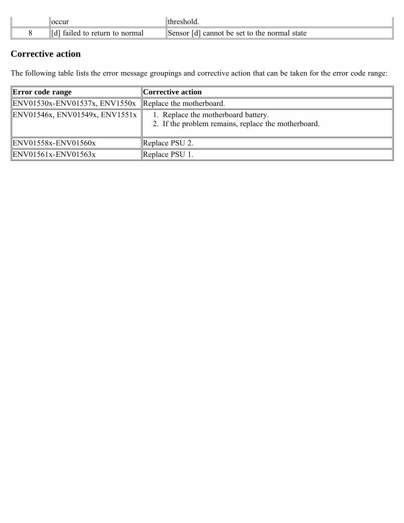
occur threshold.8 [d] failed to return to normal Sensor [d] cannot be set to the normal state
Corrective action
The following table lists the error message groupings and corrective action that can be taken for the error code range:
Error code range Corrective actionENV01530x-ENV01537x, ENV1550x Replace the motherboard.ENV01546x, ENV01549x, ENV1551x 1. Replace the motherboard battery.
2. If the problem remains, replace the motherboard.
ENV01558x-ENV01560x Replace PSU 2.ENV01561x-ENV01563x Replace PSU 1.
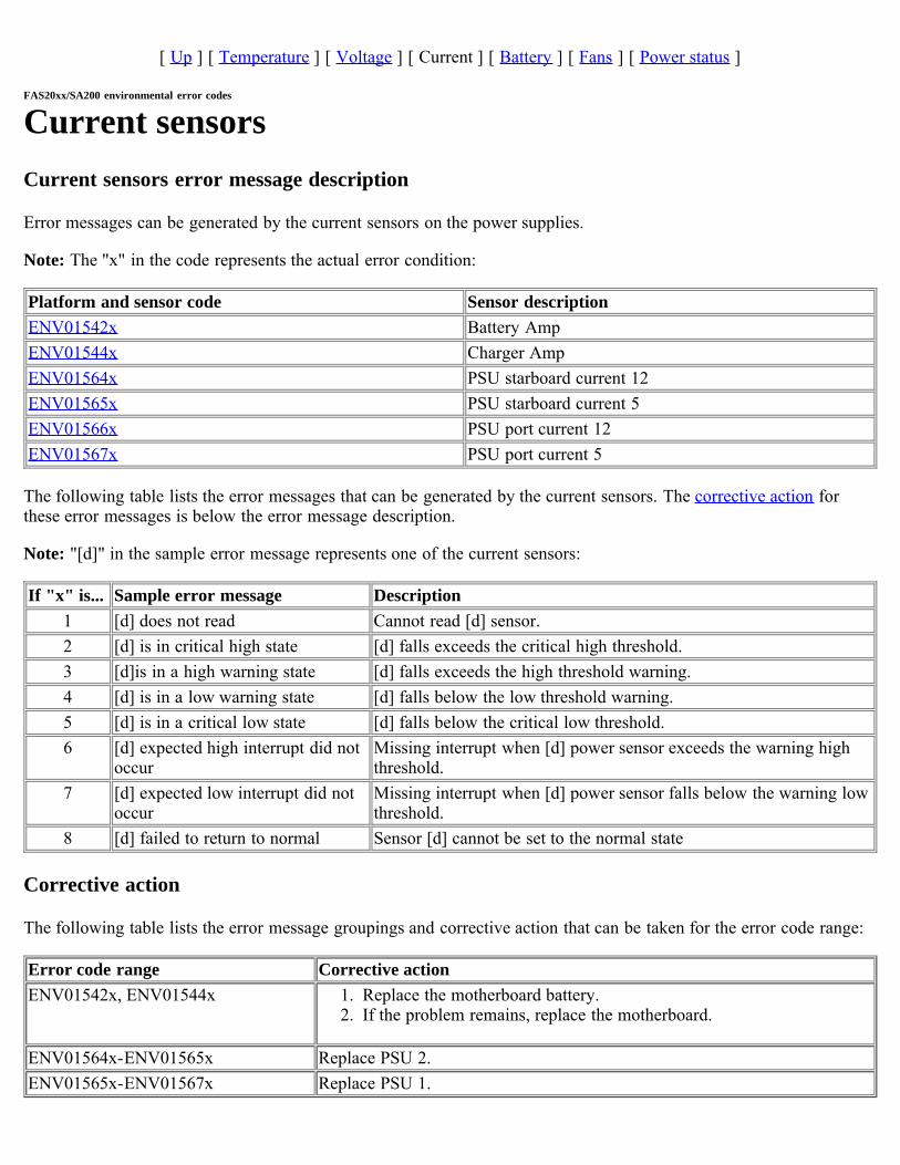
[ Up ] [ Temperature ] [ Voltage ] [ Current ] [ Battery ] [ Fans ] [ Power status ]
FAS20xx/SA200 environmental error codes
Current sensorsCurrent sensors error message description
Error messages can be generated by the current sensors on the power supplies.
Note: The "x" in the code represents the actual error condition:
Platform and sensor code Sensor descriptionENV01542x Battery AmpENV01544x Charger AmpENV01564x PSU starboard current 12ENV01565x PSU starboard current 5ENV01566x PSU port current 12ENV01567x PSU port current 5
The following table lists the error messages that can be generated by the current sensors. The corrective action forthese error messages is below the error message description.
Note: "[d]" in the sample error message represents one of the current sensors:
If "x" is... Sample error message Description1 [d] does not read Cannot read [d] sensor.2 [d] is in critical high state [d] falls exceeds the critical high threshold.3 [d]is in a high warning state [d] falls exceeds the high threshold warning.4 [d] is in a low warning state [d] falls below the low threshold warning.5 [d] is in a critical low state [d] falls below the critical low threshold.6 [d] expected high interrupt did not
occurMissing interrupt when [d] power sensor exceeds the warning highthreshold.
7 [d] expected low interrupt did notoccur
Missing interrupt when [d] power sensor falls below the warning lowthreshold.
8 [d] failed to return to normal Sensor [d] cannot be set to the normal state
Corrective action
The following table lists the error message groupings and corrective action that can be taken for the error code range:
Error code range Corrective actionENV01542x, ENV01544x 1. Replace the motherboard battery.
2. If the problem remains, replace the motherboard.
ENV01564x-ENV01565x Replace PSU 2.ENV01565x-ENV01567x Replace PSU 1.
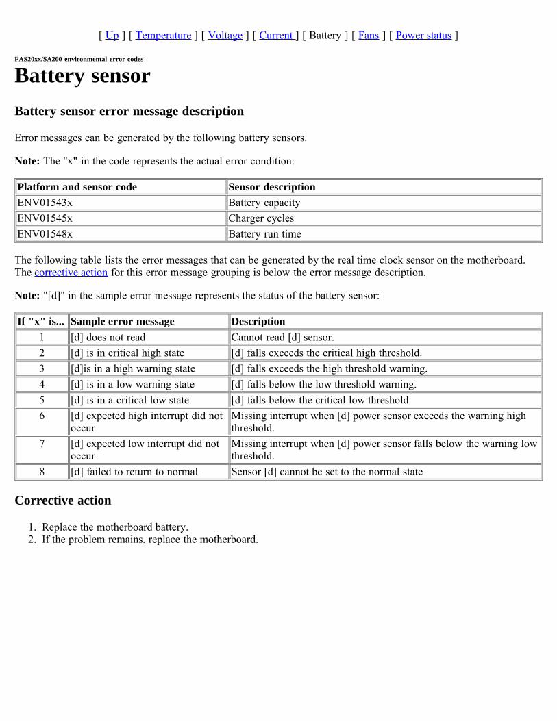
[ Up ] [ Temperature ] [ Voltage ] [ Current ] [ Battery ] [ Fans ] [ Power status ]
FAS20xx/SA200 environmental error codes
Battery sensorBattery sensor error message description
Error messages can be generated by the following battery sensors.
Note: The "x" in the code represents the actual error condition:
Platform and sensor code Sensor descriptionENV01543x Battery capacityENV01545x Charger cyclesENV01548x Battery run time
The following table lists the error messages that can be generated by the real time clock sensor on the motherboard.The corrective action for this error message grouping is below the error message description.
Note: "[d]" in the sample error message represents the status of the battery sensor:
If "x" is... Sample error message Description1 [d] does not read Cannot read [d] sensor.2 [d] is in critical high state [d] falls exceeds the critical high threshold.3 [d]is in a high warning state [d] falls exceeds the high threshold warning.4 [d] is in a low warning state [d] falls below the low threshold warning.5 [d] is in a critical low state [d] falls below the critical low threshold.6 [d] expected high interrupt did not
occurMissing interrupt when [d] power sensor exceeds the warning highthreshold.
7 [d] expected low interrupt did notoccur
Missing interrupt when [d] power sensor falls below the warning lowthreshold.
8 [d] failed to return to normal Sensor [d] cannot be set to the normal state
Corrective action
1. Replace the motherboard battery.2. If the problem remains, replace the motherboard.
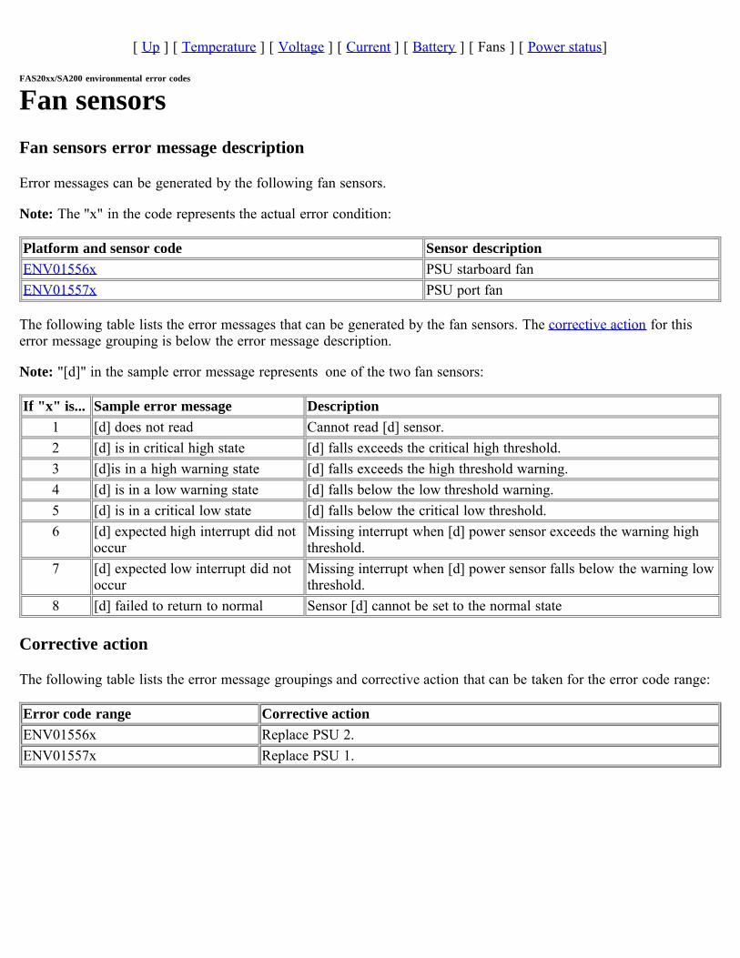
[ Up ] [ Temperature ] [ Voltage ] [ Current ] [ Battery ] [ Fans ] [ Power status]
FAS20xx/SA200 environmental error codes
Fan sensorsFan sensors error message description
Error messages can be generated by the following fan sensors.
Note: The "x" in the code represents the actual error condition:
Platform and sensor code Sensor descriptionENV01556x PSU starboard fanENV01557x PSU port fan
The following table lists the error messages that can be generated by the fan sensors. The corrective action for thiserror message grouping is below the error message description.
Note: "[d]" in the sample error message represents one of the two fan sensors:
If "x" is... Sample error message Description1 [d] does not read Cannot read [d] sensor.2 [d] is in critical high state [d] falls exceeds the critical high threshold.3 [d]is in a high warning state [d] falls exceeds the high threshold warning.4 [d] is in a low warning state [d] falls below the low threshold warning.5 [d] is in a critical low state [d] falls below the critical low threshold.6 [d] expected high interrupt did not
occurMissing interrupt when [d] power sensor exceeds the warning highthreshold.
7 [d] expected low interrupt did notoccur
Missing interrupt when [d] power sensor falls below the warning lowthreshold.
8 [d] failed to return to normal Sensor [d] cannot be set to the normal state
Corrective action
The following table lists the error message groupings and corrective action that can be taken for the error code range:
Error code range Corrective actionENV01556x Replace PSU 2.ENV01557x Replace PSU 1.
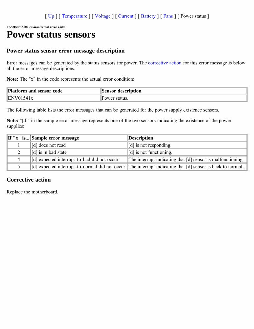
[ Up ] [ Temperature ] [ Voltage ] [ Current ] [ Battery ] [ Fans ] [ Power status ]
FAS20xx/SA200 environmental error codes
Power status sensorsPower status sensor error message description
Error messages can be generated by the status sensors for power. The corrective action for this error message is belowall the error message descriptions.
Note: The "x" in the code represents the actual error condition:
Platform and sensor code Sensor descriptionENV01541x Power status.
The following table lists the error messages that can be generated for the power supply existence sensors.
Note: "[d]" in the sample error message represents one of the two sensors indicating the existence of the powersupplies:
If "x" is... Sample error message Description1 [d] does not read [d] is not responding.2 [d] is in bad state [d] is not functioning.4 [d] expected interrupt-to-bad did not occur The interrupt indicating that [d] sensor is malfunctioning.5 [d] expected interrupt-to-normal did not occur The interrupt indicating that [d] sensor is back to normal.
Corrective action
Replace the motherboard.

FAS3020/V3020 environmental error codesMessage type
The FAS3020/V3020 environmental error messages are tabulated according to the sensors that generate them:
Temperature sensorsVoltage power sensorsChassis and CPU fan sensorsPower supply sensors

[ Up ] [ Temperature ] [ Voltage power ] [ Fans ] [ Power supply ]
FAS3020/V3020 environmental error codes
Temperature sensorsTemperature sensor error message description
Error messages can be generated by the following temperature sensors.
Note: The "x" in the code represents the actual error condition:
Platform and sensor code Sensor descriptionENV01240x CPU 1 temperature (computer processing unit 1 temp).ENV01241x CPU 2 temperature (computer processing unit 2 temp).ENV01247x PSU 1 temperature (power supply 1 temp).ENV01248x PSU 2 temperature (power supply 2 temp).ENV01251x Backplane MB temperature (backplane motherboard temp).ENV01252x Backplane HDD temperature (backplane hard disk drive temp).ENV01253x Front panel temperature (Front panel temp).
The following table lists the error messages that can be generated by the temperature sensors on the motherboard. Thecorrective action for this error message grouping is below the error message description.
Note: "[d]" in the sample error message represents one of the four temperature sensors:
If "x"is...
Sample error message Description
1 [d] does not read Cannot read [d].2 [d] is in critical high state [d] exceeds the critical high threshold.3 [d] is in warning high state [d] exceeds the warning high threshold.4 [d] is in warning low state [d] falls below the warning low threshold.5 [d] is in critical low state [d] falls below the critical low threshold.6 [d] expected high interrupt did not
occurMissing interrupt when [d] exceeds the warning high threshold.
7 [d] expected low interrupt did not occur Missing interrupt when [d] falls below the warning lowthreshold.
Corrective action
1. Check to see whether the PSU fans are working properly (from the Diagnostics menu, as well as by physicallylooking at them).
2. If the fans are bad, replace the PSUs.3. If the fans are good, replace the motherboard.
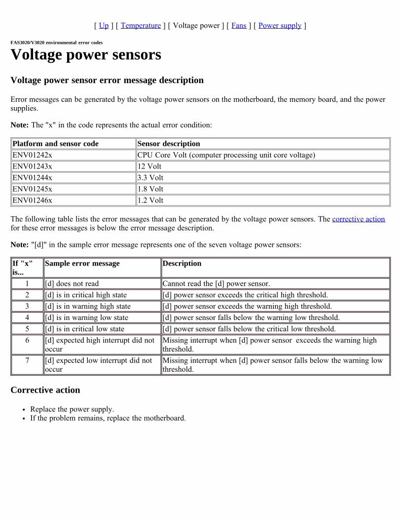
[ Up ] [ Temperature ] [ Voltage power ] [ Fans ] [ Power supply ]
FAS3020/V3020 environmental error codes
Voltage power sensorsVoltage power sensor error message description
Error messages can be generated by the voltage power sensors on the motherboard, the memory board, and the powersupplies.
Note: The "x" in the code represents the actual error condition:
Platform and sensor code Sensor descriptionENV01242x CPU Core Volt (computer processing unit core voltage)ENV01243x 12 VoltENV01244x 3.3 VoltENV01245x 1.8 VoltENV01246x 1.2 Volt
The following table lists the error messages that can be generated by the voltage power sensors. The corrective actionfor these error messages is below the error message description.
Note: "[d]" in the sample error message represents one of the seven voltage power sensors:
If "x"is...
Sample error message Description
1 [d] does not read Cannot read the [d] power sensor.2 [d] is in critical high state [d] power sensor exceeds the critical high threshold.3 [d] is in warning high state [d] power sensor exceeds the warning high threshold.4 [d] is in warning low state [d] power sensor falls below the warning low threshold.5 [d] is in critical low state [d] power sensor falls below the critical low threshold.6 [d] expected high interrupt did not
occurMissing interrupt when [d] power sensor exceeds the warning highthreshold.
7 [d] expected low interrupt did notoccur
Missing interrupt when [d] power sensor falls below the warning lowthreshold.
Corrective action
Replace the power supply.If the problem remains, replace the motherboard.
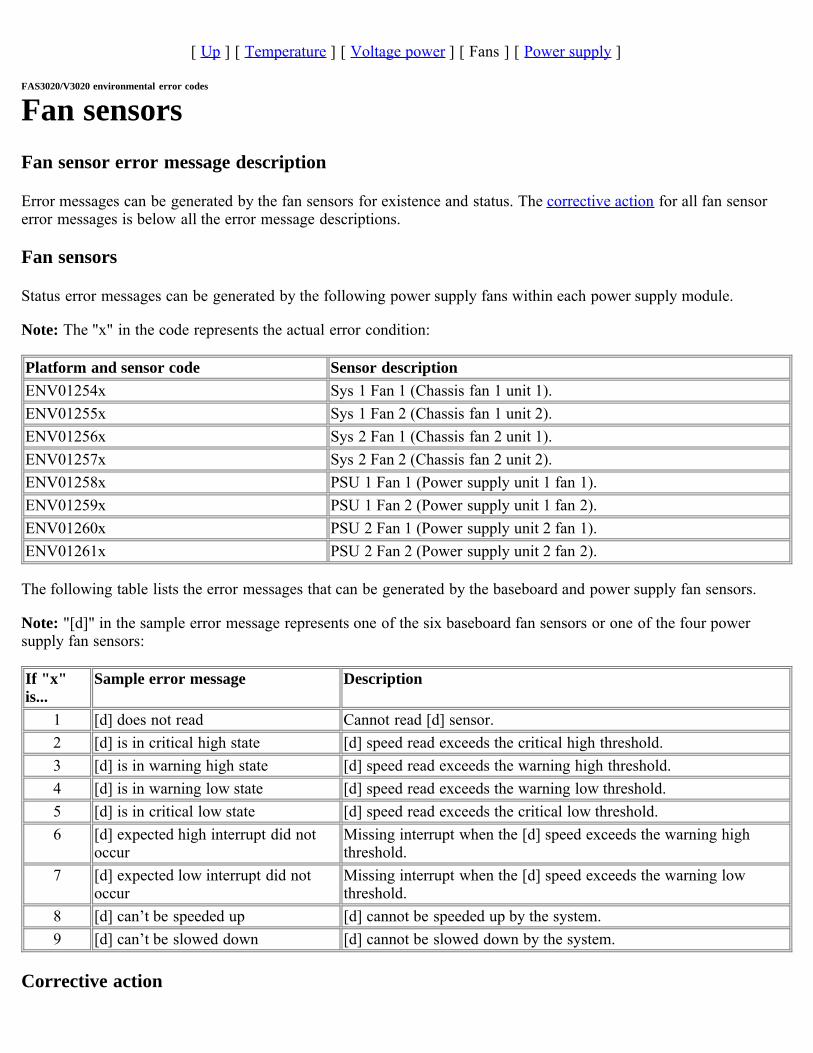
[ Up ] [ Temperature ] [ Voltage power ] [ Fans ] [ Power supply ]
FAS3020/V3020 environmental error codes
Fan sensorsFan sensor error message description
Error messages can be generated by the fan sensors for existence and status. The corrective action for all fan sensorerror messages is below all the error message descriptions.
Fan sensors
Status error messages can be generated by the following power supply fans within each power supply module.
Note: The "x" in the code represents the actual error condition:
Platform and sensor code Sensor descriptionENV01254x Sys 1 Fan 1 (Chassis fan 1 unit 1).ENV01255x Sys 1 Fan 2 (Chassis fan 1 unit 2).ENV01256x Sys 2 Fan 1 (Chassis fan 2 unit 1).ENV01257x Sys 2 Fan 2 (Chassis fan 2 unit 2).ENV01258x PSU 1 Fan 1 (Power supply unit 1 fan 1).ENV01259x PSU 1 Fan 2 (Power supply unit 1 fan 2).ENV01260x PSU 2 Fan 1 (Power supply unit 2 fan 1).ENV01261x PSU 2 Fan 2 (Power supply unit 2 fan 2).
The following table lists the error messages that can be generated by the baseboard and power supply fan sensors.
Note: "[d]" in the sample error message represents one of the six baseboard fan sensors or one of the four powersupply fan sensors:
If "x"is...
Sample error message Description
1 [d] does not read Cannot read [d] sensor.2 [d] is in critical high state [d] speed read exceeds the critical high threshold.3 [d] is in warning high state [d] speed read exceeds the warning high threshold.4 [d] is in warning low state [d] speed read exceeds the warning low threshold.5 [d] is in critical low state [d] speed read exceeds the critical low threshold.6 [d] expected high interrupt did not
occurMissing interrupt when the [d] speed exceeds the warning highthreshold.
7 [d] expected low interrupt did notoccur
Missing interrupt when the [d] speed exceeds the warning lowthreshold.
8 [d] can’t be speeded up [d] cannot be speeded up by the system.9 [d] can’t be slowed down [d] cannot be slowed down by the system.
Corrective action

Replace the power supply unit.

[ Up ] [ Temperature ] [ Voltage power ] [ Fans ] [ Power supply ]
FAS3020/V3020 environmental error codes
Power supply sensorsPower supply sensor error message description
Error messages can be generated by the power supply sensors for existence and status. The corrective action for allpower supply sensor error messages is below all the error message descriptions.
Power supply sensors for existence
Error messages can be generated by the power supply sensors for existence.
Note: The "x" in the code represents the actual error condition:
Platform and sensor code Sensor description for existenceENV01249x PSU1ENV01250x PSU2
The following table lists the error messages that can be generated for the power supply existence sensors.
Note: "[d]" in the sample error message represents one of the two sensors indicating the existence of the powersupplies:
If "x" is... Sample error message Description2 [d] is not installed [d] is missing.3 [d] is installed, but powered off [d] is off.4 [d] is installed and powered on, but not functioning [d] is not functioning.
Corrective action
1. Install the power supply.2. Turn the power supply on. 3. Replace the power supply.
FAS3040/FAS3070/V3040/V3070 environmental errorcodesMessage type
The FAS3040/FAS3070/V3040/V3070 environmental error messages are tabulated according to the sensors thatgenerate them:
Temperature sensorsVoltage power sensorsChassis and CPU fan sensorsPower supply sensors
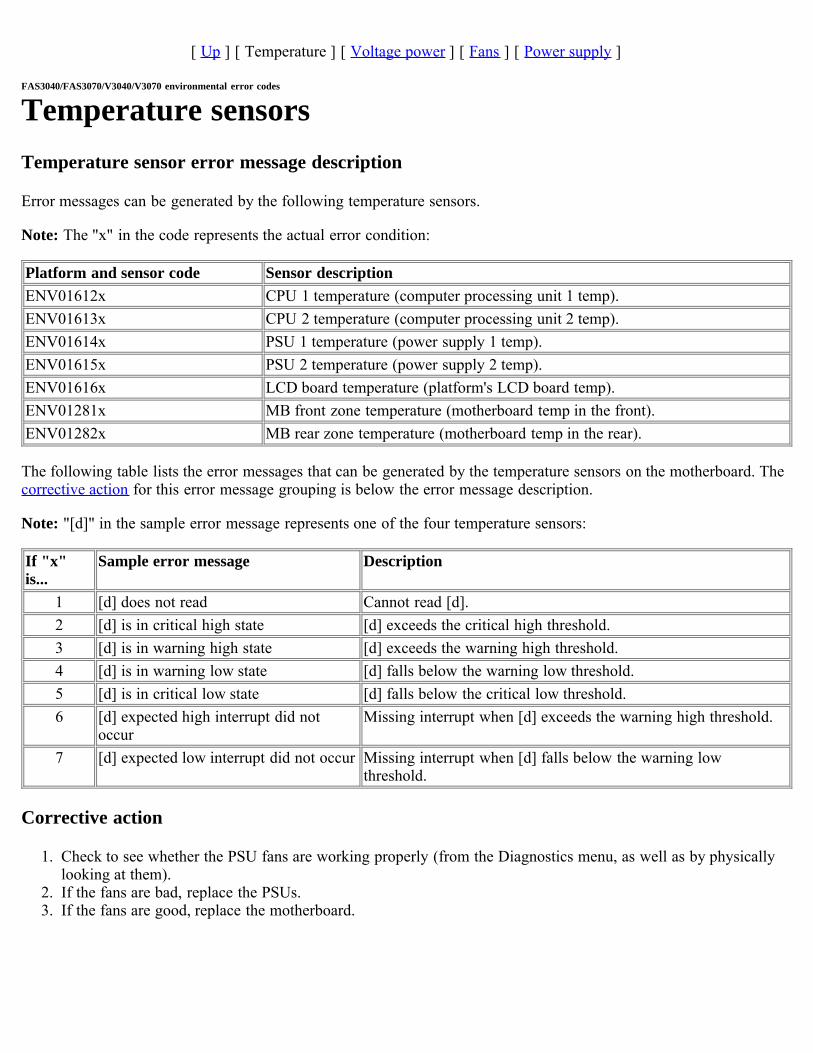
[ Up ] [ Temperature ] [ Voltage power ] [ Fans ] [ Power supply ]
FAS3040/FAS3070/V3040/V3070 environmental error codes
Temperature sensorsTemperature sensor error message description
Error messages can be generated by the following temperature sensors.
Note: The "x" in the code represents the actual error condition:
Platform and sensor code Sensor descriptionENV01612x CPU 1 temperature (computer processing unit 1 temp).ENV01613x CPU 2 temperature (computer processing unit 2 temp).ENV01614x PSU 1 temperature (power supply 1 temp).ENV01615x PSU 2 temperature (power supply 2 temp).ENV01616x LCD board temperature (platform's LCD board temp).ENV01281x MB front zone temperature (motherboard temp in the front).ENV01282x MB rear zone temperature (motherboard temp in the rear).
The following table lists the error messages that can be generated by the temperature sensors on the motherboard. Thecorrective action for this error message grouping is below the error message description.
Note: "[d]" in the sample error message represents one of the four temperature sensors:
If "x"is...
Sample error message Description
1 [d] does not read Cannot read [d].2 [d] is in critical high state [d] exceeds the critical high threshold.3 [d] is in warning high state [d] exceeds the warning high threshold.4 [d] is in warning low state [d] falls below the warning low threshold.5 [d] is in critical low state [d] falls below the critical low threshold.6 [d] expected high interrupt did not
occurMissing interrupt when [d] exceeds the warning high threshold.
7 [d] expected low interrupt did not occur Missing interrupt when [d] falls below the warning lowthreshold.
Corrective action
1. Check to see whether the PSU fans are working properly (from the Diagnostics menu, as well as by physicallylooking at them).
2. If the fans are bad, replace the PSUs.3. If the fans are good, replace the motherboard.
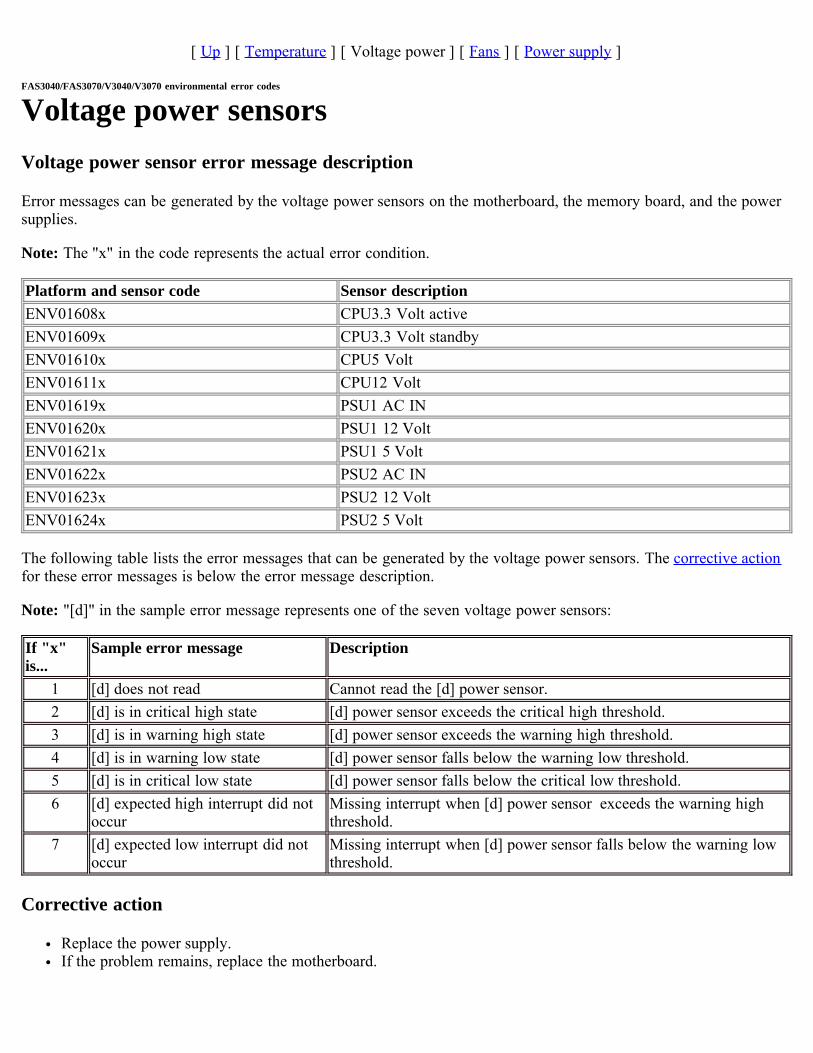
[ Up ] [ Temperature ] [ Voltage power ] [ Fans ] [ Power supply ]
FAS3040/FAS3070/V3040/V3070 environmental error codes
Voltage power sensorsVoltage power sensor error message description
Error messages can be generated by the voltage power sensors on the motherboard, the memory board, and the powersupplies.
Note: The "x" in the code represents the actual error condition.
Platform and sensor code Sensor descriptionENV01608x CPU3.3 Volt activeENV01609x CPU3.3 Volt standbyENV01610x CPU5 VoltENV01611x CPU12 VoltENV01619x PSU1 AC INENV01620x PSU1 12 VoltENV01621x PSU1 5 VoltENV01622x PSU2 AC INENV01623x PSU2 12 VoltENV01624x PSU2 5 Volt
The following table lists the error messages that can be generated by the voltage power sensors. The corrective actionfor these error messages is below the error message description.
Note: "[d]" in the sample error message represents one of the seven voltage power sensors:
If "x"is...
Sample error message Description
1 [d] does not read Cannot read the [d] power sensor.2 [d] is in critical high state [d] power sensor exceeds the critical high threshold.3 [d] is in warning high state [d] power sensor exceeds the warning high threshold.4 [d] is in warning low state [d] power sensor falls below the warning low threshold.5 [d] is in critical low state [d] power sensor falls below the critical low threshold.6 [d] expected high interrupt did not
occurMissing interrupt when [d] power sensor exceeds the warning highthreshold.
7 [d] expected low interrupt did notoccur
Missing interrupt when [d] power sensor falls below the warning lowthreshold.
Corrective action
Replace the power supply.If the problem remains, replace the motherboard.
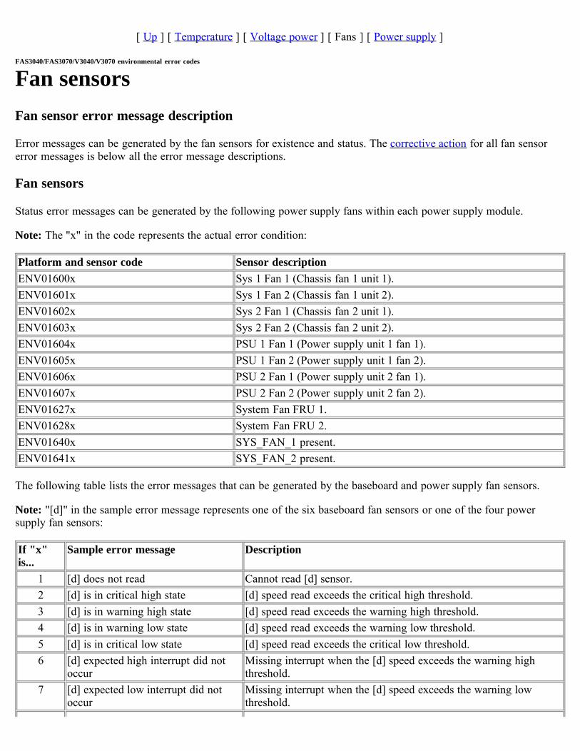
[ Up ] [ Temperature ] [ Voltage power ] [ Fans ] [ Power supply ]
FAS3040/FAS3070/V3040/V3070 environmental error codes
Fan sensorsFan sensor error message description
Error messages can be generated by the fan sensors for existence and status. The corrective action for all fan sensorerror messages is below all the error message descriptions.
Fan sensors
Status error messages can be generated by the following power supply fans within each power supply module.
Note: The "x" in the code represents the actual error condition:
Platform and sensor code Sensor descriptionENV01600x Sys 1 Fan 1 (Chassis fan 1 unit 1).ENV01601x Sys 1 Fan 2 (Chassis fan 1 unit 2).ENV01602x Sys 2 Fan 1 (Chassis fan 2 unit 1).ENV01603x Sys 2 Fan 2 (Chassis fan 2 unit 2).ENV01604x PSU 1 Fan 1 (Power supply unit 1 fan 1).ENV01605x PSU 1 Fan 2 (Power supply unit 1 fan 2).ENV01606x PSU 2 Fan 1 (Power supply unit 2 fan 1).ENV01607x PSU 2 Fan 2 (Power supply unit 2 fan 2).ENV01627x System Fan FRU 1.ENV01628x System Fan FRU 2.ENV01640x SYS_FAN_1 present.ENV01641x SYS_FAN_2 present.
The following table lists the error messages that can be generated by the baseboard and power supply fan sensors.
Note: "[d]" in the sample error message represents one of the six baseboard fan sensors or one of the four powersupply fan sensors:
If "x"is...
Sample error message Description
1 [d] does not read Cannot read [d] sensor.2 [d] is in critical high state [d] speed read exceeds the critical high threshold.3 [d] is in warning high state [d] speed read exceeds the warning high threshold.4 [d] is in warning low state [d] speed read exceeds the warning low threshold.5 [d] is in critical low state [d] speed read exceeds the critical low threshold.6 [d] expected high interrupt did not
occurMissing interrupt when the [d] speed exceeds the warning highthreshold.
7 [d] expected low interrupt did notoccur
Missing interrupt when the [d] speed exceeds the warning lowthreshold.

8 [d] can’t be speeded up [d] cannot be speeded up by the system.9 [d] can’t be slowed down [d] cannot be slowed down by the system.
Corrective action
Replace the power supply unit.
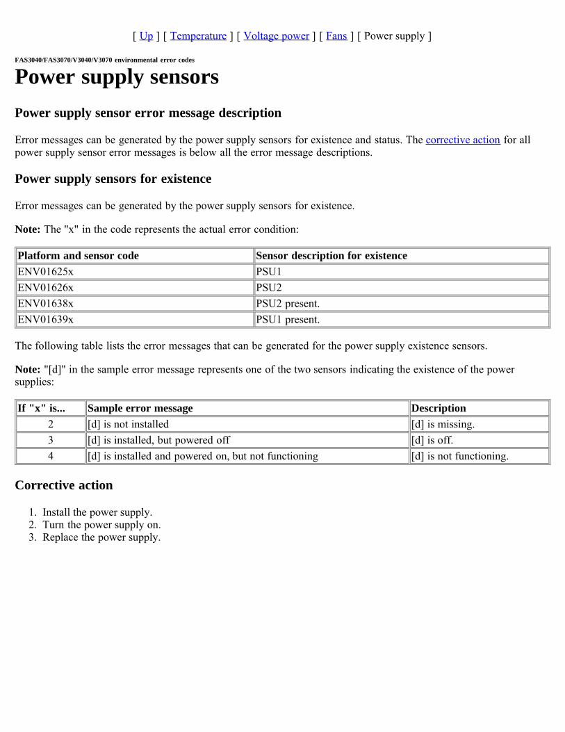
[ Up ] [ Temperature ] [ Voltage power ] [ Fans ] [ Power supply ]
FAS3040/FAS3070/V3040/V3070 environmental error codes
Power supply sensorsPower supply sensor error message description
Error messages can be generated by the power supply sensors for existence and status. The corrective action for allpower supply sensor error messages is below all the error message descriptions.
Power supply sensors for existence
Error messages can be generated by the power supply sensors for existence.
Note: The "x" in the code represents the actual error condition:
Platform and sensor code Sensor description for existenceENV01625x PSU1ENV01626x PSU2ENV01638x PSU2 present.ENV01639x PSU1 present.
The following table lists the error messages that can be generated for the power supply existence sensors.
Note: "[d]" in the sample error message represents one of the two sensors indicating the existence of the powersupplies:
If "x" is... Sample error message Description2 [d] is not installed [d] is missing.3 [d] is installed, but powered off [d] is off.4 [d] is installed and powered on, but not functioning [d] is not functioning.
Corrective action
1. Install the power supply.2. Turn the power supply on. 3. Replace the power supply.

FAS31xx/V31xx environmental error codesMessage type
The FAS31xx/V31xx environmental error messages are tabulated according to the sensors that generate them:
Temperature sensorsVoltage power sensorsChassis and CPU fan sensorsPower supply sensors
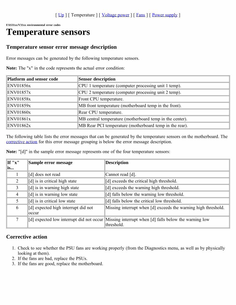
[ Up ] [ Temperature ] [ Voltage power ] [ Fans ] [ Power supply ]
FAS31xx/V31xx environmental error codes
Temperature sensorsTemperature sensor error message description
Error messages can be generated by the following temperature sensors.
Note: The "x" in the code represents the actual error condition:
Platform and sensor code Sensor descriptionENV01856x CPU 1 temperature (computer processing unit 1 temp).ENV01857x CPU 2 temperature (computer processing unit 2 temp).ENV01858x Front CPU temperature.ENV01859x MB front temperature (motherboard temp in the front).ENV01860x Rear CPU temperature.ENV01861x MB central temperature (motherboard temp in the center).ENV01862x MB Rear PCI temperature (motherboard temp in the rear).
The following table lists the error messages that can be generated by the temperature sensors on the motherboard. Thecorrective action for this error message grouping is below the error message description.
Note: "[d]" in the sample error message represents one of the four temperature sensors:
If "x"is...
Sample error message Description
1 [d] does not read Cannot read [d].2 [d] is in critical high state [d] exceeds the critical high threshold.3 [d] is in warning high state [d] exceeds the warning high threshold.4 [d] is in warning low state [d] falls below the warning low threshold.5 [d] is in critical low state [d] falls below the critical low threshold.6 [d] expected high interrupt did not
occurMissing interrupt when [d] exceeds the warning high threshold.
7 [d] expected low interrupt did not occur Missing interrupt when [d] falls below the warning lowthreshold.
Corrective action
1. Check to see whether the PSU fans are working properly (from the Diagnostics menu, as well as by physicallylooking at them).
2. If the fans are bad, replace the PSUs.3. If the fans are good, replace the motherboard.
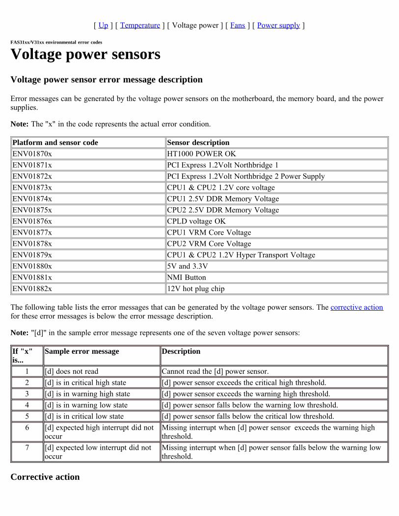
[ Up ] [ Temperature ] [ Voltage power ] [ Fans ] [ Power supply ]
FAS31xx/V31xx environmental error codes
Voltage power sensorsVoltage power sensor error message description
Error messages can be generated by the voltage power sensors on the motherboard, the memory board, and the powersupplies.
Note: The "x" in the code represents the actual error condition.
Platform and sensor code Sensor descriptionENV01870x HT1000 POWER OKENV01871x PCI Express 1.2Volt Northbridge 1ENV01872x PCI Express 1.2Volt Northbridge 2 Power SupplyENV01873x CPU1 & CPU2 1.2V core voltageENV01874x CPU1 2.5V DDR Memory VoltageENV01875x CPU2 2.5V DDR Memory VoltageENV01876x CPLD voltage OKENV01877x CPU1 VRM Core VoltageENV01878x CPU2 VRM Core VoltageENV01879x CPU1 & CPU2 1.2V Hyper Transport VoltageENV01880x 5V and 3.3VENV01881x NMI ButtonENV01882x 12V hot plug chip
The following table lists the error messages that can be generated by the voltage power sensors. The corrective actionfor these error messages is below the error message description.
Note: "[d]" in the sample error message represents one of the seven voltage power sensors:
If "x"is...
Sample error message Description
1 [d] does not read Cannot read the [d] power sensor.2 [d] is in critical high state [d] power sensor exceeds the critical high threshold.3 [d] is in warning high state [d] power sensor exceeds the warning high threshold.4 [d] is in warning low state [d] power sensor falls below the warning low threshold.5 [d] is in critical low state [d] power sensor falls below the critical low threshold.6 [d] expected high interrupt did not
occurMissing interrupt when [d] power sensor exceeds the warning highthreshold.
7 [d] expected low interrupt did notoccur
Missing interrupt when [d] power sensor falls below the warning lowthreshold.
Corrective action

Replace the power supply.If the problem remains, replace the motherboard.
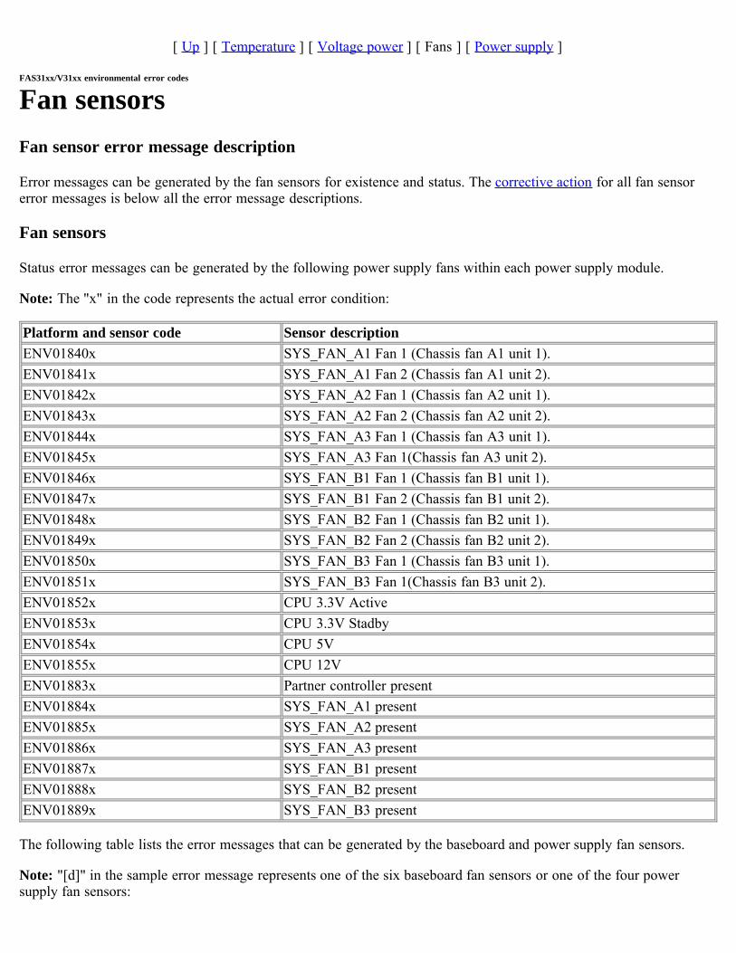
[ Up ] [ Temperature ] [ Voltage power ] [ Fans ] [ Power supply ]
FAS31xx/V31xx environmental error codes
Fan sensorsFan sensor error message description
Error messages can be generated by the fan sensors for existence and status. The corrective action for all fan sensorerror messages is below all the error message descriptions.
Fan sensors
Status error messages can be generated by the following power supply fans within each power supply module.
Note: The "x" in the code represents the actual error condition:
Platform and sensor code Sensor descriptionENV01840x SYS_FAN_A1 Fan 1 (Chassis fan A1 unit 1).ENV01841x SYS_FAN_A1 Fan 2 (Chassis fan A1 unit 2).ENV01842x SYS_FAN_A2 Fan 1 (Chassis fan A2 unit 1).ENV01843x SYS_FAN_A2 Fan 2 (Chassis fan A2 unit 2).ENV01844x SYS_FAN_A3 Fan 1 (Chassis fan A3 unit 1).ENV01845x SYS_FAN_A3 Fan 1(Chassis fan A3 unit 2).ENV01846x SYS_FAN_B1 Fan 1 (Chassis fan B1 unit 1).ENV01847x SYS_FAN_B1 Fan 2 (Chassis fan B1 unit 2).ENV01848x SYS_FAN_B2 Fan 1 (Chassis fan B2 unit 1).ENV01849x SYS_FAN_B2 Fan 2 (Chassis fan B2 unit 2).ENV01850x SYS_FAN_B3 Fan 1 (Chassis fan B3 unit 1).ENV01851x SYS_FAN_B3 Fan 1(Chassis fan B3 unit 2).ENV01852x CPU 3.3V ActiveENV01853x CPU 3.3V StadbyENV01854x CPU 5VENV01855x CPU 12VENV01883x Partner controller presentENV01884x SYS_FAN_A1 presentENV01885x SYS_FAN_A2 presentENV01886x SYS_FAN_A3 presentENV01887x SYS_FAN_B1 presentENV01888x SYS_FAN_B2 presentENV01889x SYS_FAN_B3 present
The following table lists the error messages that can be generated by the baseboard and power supply fan sensors.
Note: "[d]" in the sample error message represents one of the six baseboard fan sensors or one of the four powersupply fan sensors:
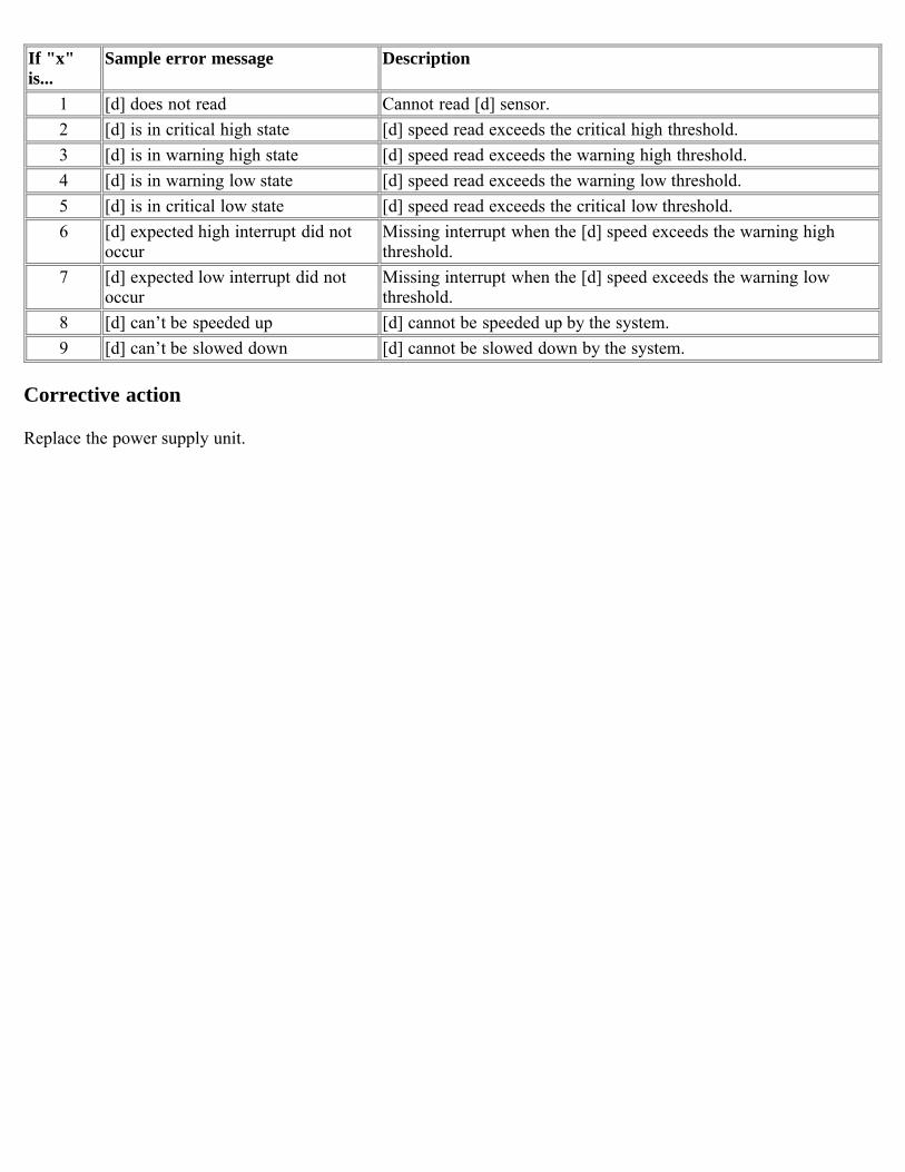
If "x"is...
Sample error message Description
1 [d] does not read Cannot read [d] sensor.2 [d] is in critical high state [d] speed read exceeds the critical high threshold.3 [d] is in warning high state [d] speed read exceeds the warning high threshold.4 [d] is in warning low state [d] speed read exceeds the warning low threshold.5 [d] is in critical low state [d] speed read exceeds the critical low threshold.6 [d] expected high interrupt did not
occurMissing interrupt when the [d] speed exceeds the warning highthreshold.
7 [d] expected low interrupt did notoccur
Missing interrupt when the [d] speed exceeds the warning lowthreshold.
8 [d] can’t be speeded up [d] cannot be speeded up by the system.9 [d] can’t be slowed down [d] cannot be slowed down by the system.
Corrective action
Replace the power supply unit.
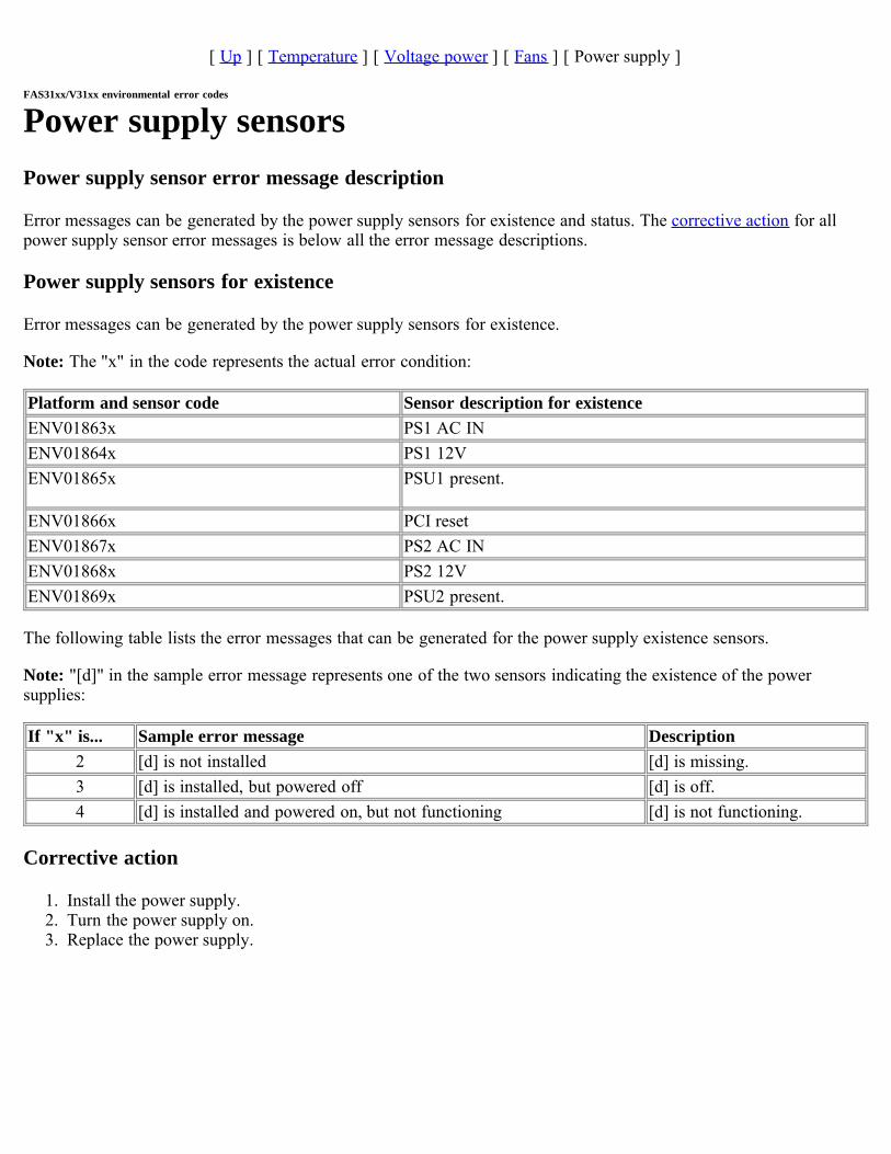
[ Up ] [ Temperature ] [ Voltage power ] [ Fans ] [ Power supply ]
FAS31xx/V31xx environmental error codes
Power supply sensorsPower supply sensor error message description
Error messages can be generated by the power supply sensors for existence and status. The corrective action for allpower supply sensor error messages is below all the error message descriptions.
Power supply sensors for existence
Error messages can be generated by the power supply sensors for existence.
Note: The "x" in the code represents the actual error condition:
Platform and sensor code Sensor description for existenceENV01863x PS1 AC INENV01864x PS1 12VENV01865x PSU1 present.
ENV01866x PCI resetENV01867x PS2 AC INENV01868x PS2 12VENV01869x PSU2 present.
The following table lists the error messages that can be generated for the power supply existence sensors.
Note: "[d]" in the sample error message represents one of the two sensors indicating the existence of the powersupplies:
If "x" is... Sample error message Description2 [d] is not installed [d] is missing.3 [d] is installed, but powered off [d] is off.4 [d] is installed and powered on, but not functioning [d] is not functioning.
Corrective action
1. Install the power supply.2. Turn the power supply on. 3. Replace the power supply.

FAS60xx/V60xx/SA600environmental error codesMessage type
The FAS60xx/V60xx/SA600 environmental error messages are tabulated according to the sensors that generate them:
Temperature sensorsVoltage power sensorsChassis and CPU fan sensorsPower supply sensors
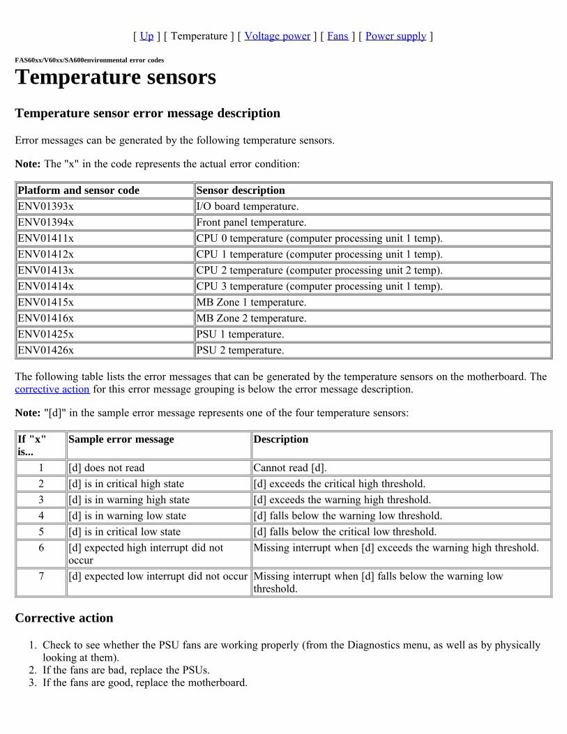
[ Up ] [ Temperature ] [ Voltage power ] [ Fans ] [ Power supply ]
FAS60xx/V60xx/SA600environmental error codes
Temperature sensorsTemperature sensor error message description
Error messages can be generated by the following temperature sensors.
Note: The "x" in the code represents the actual error condition:
Platform and sensor code Sensor descriptionENV01393x I/O board temperature.ENV01394x Front panel temperature.ENV01411x CPU 0 temperature (computer processing unit 1 temp).ENV01412x CPU 1 temperature (computer processing unit 1 temp).ENV01413x CPU 2 temperature (computer processing unit 2 temp).ENV01414x CPU 3 temperature (computer processing unit 1 temp).ENV01415x MB Zone 1 temperature.ENV01416x MB Zone 2 temperature.ENV01425x PSU 1 temperature.ENV01426x PSU 2 temperature.
The following table lists the error messages that can be generated by the temperature sensors on the motherboard. Thecorrective action for this error message grouping is below the error message description.
Note: "[d]" in the sample error message represents one of the four temperature sensors:
If "x"is...
Sample error message Description
1 [d] does not read Cannot read [d].2 [d] is in critical high state [d] exceeds the critical high threshold.3 [d] is in warning high state [d] exceeds the warning high threshold.4 [d] is in warning low state [d] falls below the warning low threshold.5 [d] is in critical low state [d] falls below the critical low threshold.6 [d] expected high interrupt did not
occurMissing interrupt when [d] exceeds the warning high threshold.
7 [d] expected low interrupt did not occur Missing interrupt when [d] falls below the warning lowthreshold.
Corrective action
1. Check to see whether the PSU fans are working properly (from the Diagnostics menu, as well as by physicallylooking at them).
2. If the fans are bad, replace the PSUs.3. If the fans are good, replace the motherboard.
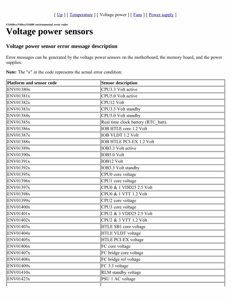
[ Up ] [ Temperature ] [ Voltage power ] [ Fans ] [ Power supply ]
FAS60xx/V60xx/SA600 environmental error codes
Voltage power sensorsVoltage power sensor error message description
Error messages can be generated by the voltage power sensors on the motherboard, the memory board, and the powersupplies.
Note: The "x" in the code represents the actual error condition:
Platform and sensor code Sensor descriptionENV01380x CPU3.3 Volt activeENV01381x CPU5.0 Volt activeENV01382x CPU12 VoltENV01383x CPU3.3 Volt standbyENV01384x CPU5.0 Volt standbyENV01385x Real time clock battery (RTC_batt).ENV01386x IOB HTLE core 1.2 VoltENV01387x IOB VLDT 1.2 VoltENV01388x IOB HTLE PCI-EX 1.2 VoltENV01389x IOB3.3 Volt activeENV01390x IOB5.0 VoltENV01391x IOB12 VoltENV01392x IOB3.3 Volt standbyENV01395x CPU0 core voltageENV01396x CPU1 core voltageENV01397x CPU0 & 1 VDD25 2.5 VoltENV01398x CPU0 & 1 VTT 1.2 VoltENV01399x CPU2 core voltageENV01400x CPU3 core voltageENV01401x CPU2 & 3 VDD25 2.5 VoltENV01402x CPU2 & 3 VTT 1.2 VoltENV01403x HTLE SB1 core voltageENV01404x HTLE VLDT voltageENV01405x HTLE PCI-EX voltageENV01406x FC core voltageENV01407x FC bridge core voltageENV01408x FC bridge ref voltageENV01409x FC 3.3 voltageENV01410x RLM standby voltageENV01423x PSU 1 AC voltage
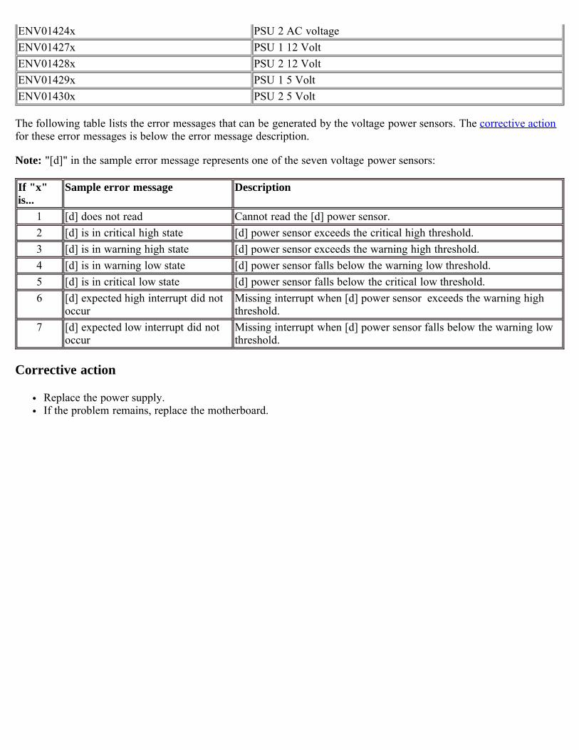
ENV01424x PSU 2 AC voltageENV01427x PSU 1 12 VoltENV01428x PSU 2 12 VoltENV01429x PSU 1 5 VoltENV01430x PSU 2 5 Volt
The following table lists the error messages that can be generated by the voltage power sensors. The corrective actionfor these error messages is below the error message description.
Note: "[d]" in the sample error message represents one of the seven voltage power sensors:
If "x"is...
Sample error message Description
1 [d] does not read Cannot read the [d] power sensor.2 [d] is in critical high state [d] power sensor exceeds the critical high threshold.3 [d] is in warning high state [d] power sensor exceeds the warning high threshold.4 [d] is in warning low state [d] power sensor falls below the warning low threshold.5 [d] is in critical low state [d] power sensor falls below the critical low threshold.6 [d] expected high interrupt did not
occurMissing interrupt when [d] power sensor exceeds the warning highthreshold.
7 [d] expected low interrupt did notoccur
Missing interrupt when [d] power sensor falls below the warning lowthreshold.
Corrective action
Replace the power supply.If the problem remains, replace the motherboard.
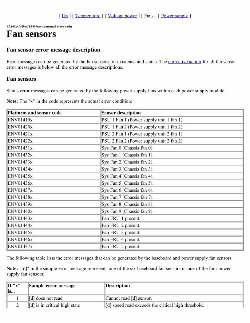
[ Up ] [ Temperature ] [ Voltage power ] [ Fans ] [ Power supply ]
FAS60xx/V60xx/SA600environmental error codes
Fan sensorsFan sensor error message description
Error messages can be generated by the fan sensors for existence and status. The corrective action for all fan sensorerror messages is below all the error message descriptions.
Fan sensors
Status error messages can be generated by the following power supply fans within each power supply module.
Note: The "x" in the code represents the actual error condition:
Platform and sensor code Sensor descriptionENV01419x PSU 1 Fan 1 (Power supply unit 1 fan 1).ENV01420x PSU 1 Fan 2 (Power supply unit 1 fan 2).ENV01421x PSU 2 Fan 1 (Power supply unit 2 fan 1).ENV01422x PSU 2 Fan 2 (Power supply unit 2 fan 2).ENV01431x Sys Fan 0 (Chassis fan 0).ENV01432x Sys Fan 1 (Chassis fan 1).ENV01433x Sys Fan 2 (Chassis fan 2).ENV01434x Sys Fan 3 (Chassis fan 3).ENV01435x Sys Fan 4 (Chassis fan 4).ENV01436x Sys Fan 5 (Chassis fan 5).ENV01437x Sys Fan 6 (Chassis fan 6).ENV01438x Sys Fan 7 (Chassis fan 7).ENV01439x Sys Fan 8 (Chassis fan 8).ENV01440x Sys Fan 9 (Chassis fan 9).ENV01443x Fan FRU 1 present.ENV01444x Fan FRU 2 present.ENV01445x Fan FRU 3 present.ENV01446x Fan FRU 4 present.ENV01447x Fan FRU 5 present.
The following table lists the error messages that can be generated by the baseboard and power supply fan sensors.
Note: "[d]" in the sample error message represents one of the six baseboard fan sensors or one of the four powersupply fan sensors:
If "x"is...
Sample error message Description
1 [d] does not read Cannot read [d] sensor.2 [d] is in critical high state [d] speed read exceeds the critical high threshold.
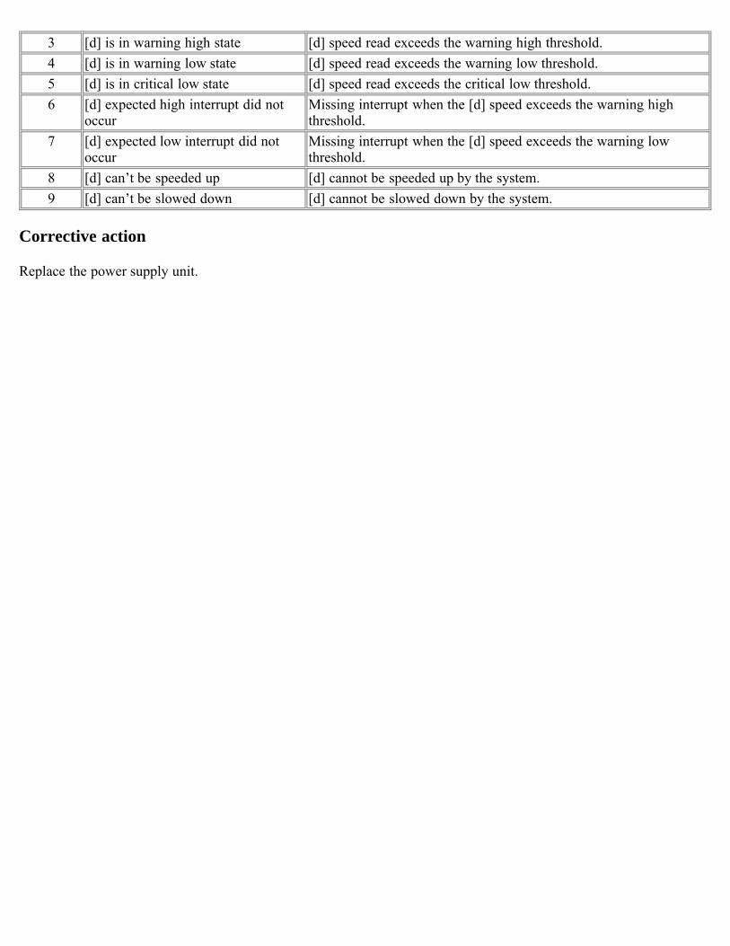
3 [d] is in warning high state [d] speed read exceeds the warning high threshold.4 [d] is in warning low state [d] speed read exceeds the warning low threshold.5 [d] is in critical low state [d] speed read exceeds the critical low threshold.6 [d] expected high interrupt did not
occurMissing interrupt when the [d] speed exceeds the warning highthreshold.
7 [d] expected low interrupt did notoccur
Missing interrupt when the [d] speed exceeds the warning lowthreshold.
8 [d] can’t be speeded up [d] cannot be speeded up by the system.9 [d] can’t be slowed down [d] cannot be slowed down by the system.
Corrective action
Replace the power supply unit.
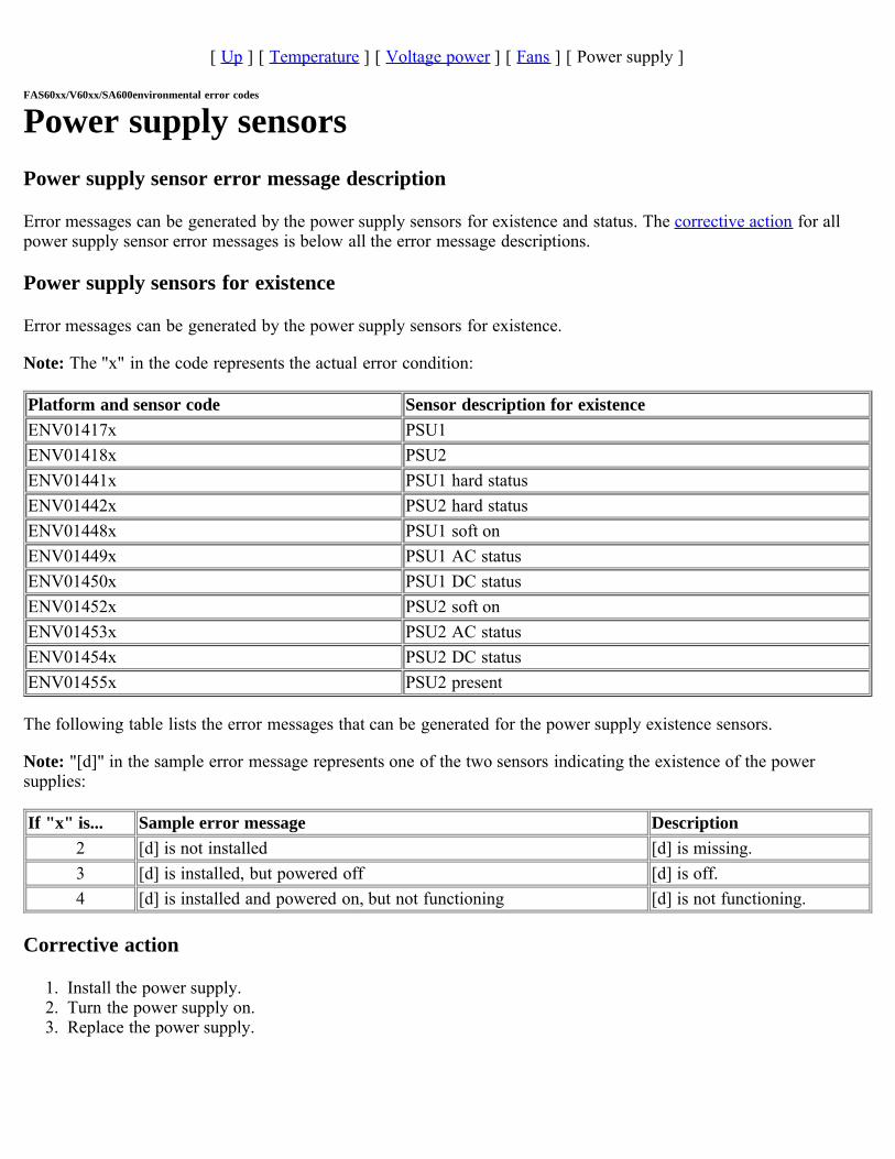
[ Up ] [ Temperature ] [ Voltage power ] [ Fans ] [ Power supply ]
FAS60xx/V60xx/SA600environmental error codes
Power supply sensorsPower supply sensor error message description
Error messages can be generated by the power supply sensors for existence and status. The corrective action for allpower supply sensor error messages is below all the error message descriptions.
Power supply sensors for existence
Error messages can be generated by the power supply sensors for existence.
Note: The "x" in the code represents the actual error condition:
Platform and sensor code Sensor description for existenceENV01417x PSU1ENV01418x PSU2ENV01441x PSU1 hard statusENV01442x PSU2 hard statusENV01448x PSU1 soft onENV01449x PSU1 AC statusENV01450x PSU1 DC statusENV01452x PSU2 soft onENV01453x PSU2 AC statusENV01454x PSU2 DC statusENV01455x PSU2 present
The following table lists the error messages that can be generated for the power supply existence sensors.
Note: "[d]" in the sample error message represents one of the two sensors indicating the existence of the powersupplies:
If "x" is... Sample error message Description2 [d] is not installed [d] is missing.3 [d] is installed, but powered off [d] is off.4 [d] is installed and powered on, but not functioning [d] is not functioning.
Corrective action
1. Install the power supply.2. Turn the power supply on. 3. Replace the power supply.