
DIAGNOSIS PUMP PROBLEMS USING VIBRATION ANALYSIS …
16
European Journal of Mechanical Engineering Research Vol.3, No.3, pp.18-94, August 2016 ___Published by European Centre for Research Training and Development UK (www.eajournals.org) 18 ISSN 2055-6551(Print), ISSN 2055-656X (Online) DIAGNOSIS PUMP PROBLEMS USING VIBRATION ANALYSIS Sami A. A. El-Shaikh Mechanical & Electrical Research Institute, National Water Research Center, Ministry of Water Resources & Irrigation, Delta Barrage, Egypt ABSTRACT: Pump stations are generally exposed to various mechanical and structural problems causing vibration affecting efficiency, performance, operating life, and maintenance cost. The motivation of this research is to identify the causes of the high vibration of El- Marashda (1) pumping station due to weakness of the foundation and support. Effect of adding steel supports to motor foundation is studied to overcome structural weakness of the pump support. Vibration level is measured and frequency analysis is done by adding steel supports gradually. From initial measurements, vibration levels measured are in the danger level. Adding steel supports to motor foundation in two steps at different locations solved the problem and reduced the high vibration level. Applying the first scenario reduced overall velocity vibration level 54%, overall acceleration level reduced 30%, and bearing defect factor reduced 20% but the problem is still there and the vibration level is high. Applying the second scenario by increasing steel support reduced the overall vibration level 91%, reduced overall acceleration level 43%, and reduced the bearing defect factor 40% than the initial state and solved the structure weakness problem and reduced the high vibration level to safe limit. Adding definitive supports to weak motor foundation of the pump enhanced the dynamic characteristics, overcame structural weakness, and reduced vibration level. Pump foundation should be carefully designed and strengthened to resist the dynamic loads. Inspection and regular maintenance is important to avoid any abnormal conditions, affecting both pump components and foundation. KEYWORDS: Pump Vibration, Support Weakness, Maintenance, Dynamic Performance. INTRODUCTION Pumping stations are subjected to many problems affecting performance, efficiency, and maintenance cost. High vibration level causes damage to the structure of the housing building and foundations of the pumping stations. Smalley [1] presented a method for assessing the severity of vibration in terms of the probability of damage by analysis of vibration and its related cost. Damage due to vibration cost millions of dollars for maintenance and replacement expenses. Vibration monitoring of pumps as a part of a good predictive maintenance program is becoming increasingly important as pressures increase to reduce damage [2] . Vibration condition monitoring as an aid to fault diagnosis of rotary machines has been used successfully since more than 30 years. However, vibration is used as an effective tool for fault detection and diagnosis. Many researches evaluate mechanical and hydraulic pump performance using vibration analysis [3, 4] . The pump baseplate is the interface between the casing feet and the foundation. A baseplate and the foundation have some degree of flexibility, and therefore are a contributing factor in the overall stiffness with which the mass of the pump is grounded mechanically to the earth. Therefore, the baseplate and foundation are often a key factor in establishing the so-called “reed” frequencies of a pump, the vibration motion that particularly vertical pumps often
Transcript of DIAGNOSIS PUMP PROBLEMS USING VIBRATION ANALYSIS …

European Journal of Mechanical Engineering Research
Vol.3, No.3, pp.18-94, August 2016
___Published by European Centre for Research Training and Development UK (www.eajournals.org)
18
ISSN 2055-6551(Print), ISSN 2055-656X (Online)
DIAGNOSIS PUMP PROBLEMS USING VIBRATION ANALYSIS
Sami A. A. El-Shaikh
Mechanical & Electrical Research Institute, National Water Research Center, Ministry of
Water Resources & Irrigation, Delta Barrage, Egypt
ABSTRACT: Pump stations are generally exposed to various mechanical and structural
problems causing vibration affecting efficiency, performance, operating life, and maintenance
cost. The motivation of this research is to identify the causes of the high vibration of El-
Marashda (1) pumping station due to weakness of the foundation and support. Effect of adding
steel supports to motor foundation is studied to overcome structural weakness of the pump
support. Vibration level is measured and frequency analysis is done by adding steel supports
gradually. From initial measurements, vibration levels measured are in the danger level.
Adding steel supports to motor foundation in two steps at different locations solved the problem
and reduced the high vibration level. Applying the first scenario reduced overall velocity
vibration level 54%, overall acceleration level reduced 30%, and bearing defect factor reduced
20% but the problem is still there and the vibration level is high. Applying the second scenario
by increasing steel support reduced the overall vibration level 91%, reduced overall
acceleration level 43%, and reduced the bearing defect factor 40% than the initial state and
solved the structure weakness problem and reduced the high vibration level to safe limit.
Adding definitive supports to weak motor foundation of the pump enhanced the dynamic
characteristics, overcame structural weakness, and reduced vibration level. Pump foundation
should be carefully designed and strengthened to resist the dynamic loads. Inspection and
regular maintenance is important to avoid any abnormal conditions, affecting both pump
components and foundation.
KEYWORDS: Pump Vibration, Support Weakness, Maintenance, Dynamic Performance.
INTRODUCTION
Pumping stations are subjected to many problems affecting performance, efficiency, and
maintenance cost. High vibration level causes damage to the structure of the housing building
and foundations of the pumping stations. Smalley [1] presented a method for assessing the
severity of vibration in terms of the probability of damage by analysis of vibration and its related
cost. Damage due to vibration cost millions of dollars for maintenance and replacement
expenses. Vibration monitoring of pumps as a part of a good predictive maintenance program
is becoming increasingly important as pressures increase to reduce damage [2]. Vibration
condition monitoring as an aid to fault diagnosis of rotary machines has been used successfully
since more than 30 years. However, vibration is used as an effective tool for fault detection
and diagnosis. Many researches evaluate mechanical and hydraulic pump performance using
vibration analysis [3, 4].
The pump baseplate is the interface between the casing feet and the foundation. A baseplate
and the foundation have some degree of flexibility, and therefore are a contributing factor in
the overall stiffness with which the mass of the pump is grounded mechanically to the earth.
Therefore, the baseplate and foundation are often a key factor in establishing the so-called
“reed” frequencies of a pump, the vibration motion that particularly vertical pumps often

European Journal of Mechanical Engineering Research
Vol.3, No.3, pp.18-94, August 2016
___Published by European Centre for Research Training and Development UK (www.eajournals.org)
19
ISSN 2055-6551(Print), ISSN 2055-656X (Online)
exhibit near running speed. This factor in the installation and qualification of new pumps is
often overlooked by civil engineers and mechanical contractors when they design and construct
a new or revised pump installation [5].
Machine foundations require a special consideration because they transmit dynamic loads to
soil in addition to static loads due to weight of foundation, machine and accessories. The
dynamic load due to operation of the machine is generally small compared to the static weight
of machine and the supporting foundation. In a machine foundation the dynamic load is applied
repetitively over a very long period of time but its magnitude is small and therefore the soil
behavior is essentially elastic, or else deformation will increase with each cycle of loading and
may become unacceptable. The amplitude of vibration of a machine at its operating frequency
is the most important parameter to be determined in designing a machine foundation, in
addition to the natural frequency of a machine foundation soil system [6]. Due to misalignment,
improper installation and pipe loads imposed due to poor support of suction and discharge
pipes. Low rigidity, other cause, of pump vibration is due to low strength of components
including casing, and low foundation strength due to weak foundations or improper tightening
of foundation bolts [7&8]. Resonance or self excited oscillation is mainly due to:
Pressure pulsation in the pump coincides with the natural frequency of casing or piping,
Vortex formed near the suction pipe, and
Speed corresponding to natural frequency of the rotating component.
Pump vibration is evaluated on the basis of the value at the center of the bearing supporting the
rotating portion. When pumps and drivers are firmly installed on a large foundation, nearly
100% of the vibration force generated by each machine is transmitted to the foundation.
Foundation vibration is proportional to their weight, and when a sufficiently large foundation
is used, both foundation vibration and pump vibration can be held to a low value. When the
size of the foundation is not so large, and its vibration is great, noise may occur in the
surroundings. Also, when the vibrating force transmitted to the foundation must be reduced
because of low building strength, vibration damping measures are necessary [8].
The effect of imbalance on a single stage end pump with the impeller cantilevered relative to
the bearings is studied. If the impeller mass is M, the mass of the shaft is Ms, the shaft length
and moment of inertia are L and, respectively, and is Young’s modulus of elasticity, then the
lowest natural frequency (the “reed” mode) in cycles per minute is:
2
1
3 ])}49.0({
)3([2
60
S
nl
MMLEI
f
nlf Lowest natural frequency
EI Young’s modulus of elasticity
L Shaft length and moment of inertia
M Impeller mass

European Journal of Mechanical Engineering Research
Vol.3, No.3, pp.18-94, August 2016
___Published by European Centre for Research Training and Development UK (www.eajournals.org)
20
ISSN 2055-6551(Print), ISSN 2055-656X (Online)
SM Mass of the shaft
If the eccentricity of the impeller relative to the bearing rotational centerline is, and the
rotational speed is rad/s, then the unbalance force is simply:
c
eub g
MF
2
ubF Unbalance Force
Rotational speed
eM Impeller mass eccentricity
cg Gravitational speed
and the amount of vibration displacement expected at the impeller wearing rings is:
EI
LFub
3* 3
METHODOLOGY
Problem Statement
In this research, mechanical problems of Marashda (1) Pumping Station are assessed. Marashda
(1) Pumping Station is used to serve irrigation of 500 feddans in Nagaa Hamadi Area in Upper
Egypt. It consists of 5 pump units as shown in Figure (1). Each pump unit is of discharge 2.2
m3/sec, head 12 m, pump speed 598 rpm, motor power 456 kW, motor speed 1483 rpm, and
gearbox ratio 62/25 (2.48), number of drive Gear teeth is 25, number of driven Gear teeth is
62, and rated output power is 430 KW.
Dynamic Analysis was done by measuring overall vibration velocity, gravity vibration
acceleration, and bearing defect factor at 12 locations on five units in three directions axial,
horizontal, and vertical perpendicular, as shown in Figure(2) and compared the results with
standards of machines (ISO 10816-1) [9], as shown in Figure (3). Frequency analysis was done
at low and high frequency to define the exciting frequencies and determine the level of
vibration at each specific frequency, to determine the sources of vibration, to control vibration
levels, and to solve vibration problems. Then, measurements were repeated twice after
maintenance and adding supports to motor foundation with load and no load conditions to fix
the high vibration level.
Equipment that used for test/measurement is one proD/ACOEM vibration analyzer and Data
collector MVP200 serial 11141 with Machine Monitoring SW type XPR300 Premium, as
shown in Figure (4).

European Journal of Mechanical Engineering Research
Vol.3, No.3, pp.18-94, August 2016
___Published by European Centre for Research Training and Development UK (www.eajournals.org)
21
ISSN 2055-6551(Print), ISSN 2055-656X (Online)
Figure (1) Photograph for Marashda (1)
P. S.
Figure (2) Measurement locations for Marashda
(1) P s
Figure (3) ISO standard for vibration Figure (4) 01dB Movipack with machine
monitoring SW type XPR300 premium
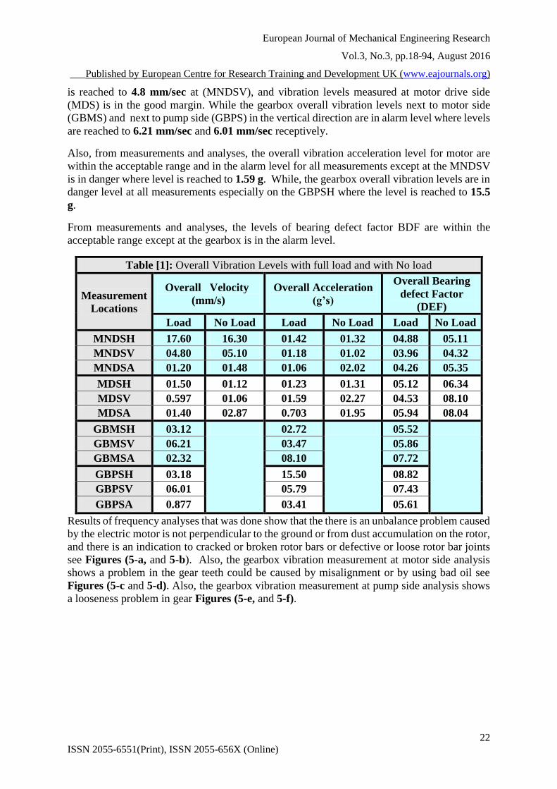
RESULTS AND ANALYSIS OF VIBRATION MEASUREMENTS
Firstly, overall vibration levels in terms of rms vibration velocity, gravity vibration
acceleration, and bearing defect factor (BDF) were measured and analyzed at load and no load
conditions. Maintenance and fixation of the problems were done and measurements were
repeated. Dynamic analyses were done at all conditions to determine seriousness and causes of
the problems. Lastly; dynamic analysis indicated disappearance of the problems.
Results of vibration measured at full load “Initial state”
Overall vibration levels that are measured with load for five units show that the level of
vibration in terms of vibration velocity, gravity vibration acceleration, and bearing defect factor
for all units are in the danger level. So, measurements were done for unit 1, with load and with
no load to judge if the problem from motor or from pump and then measurements are repeated
with load and with no load after doing maintenance, as shown in Table [1].
From measurements and analyses overall vibration velocity level for motor non drive side
(MNDS) is in danger level where level is reached to 17.6 mm/sec at (MNDSH), and the level
H
A
V
European Journal of Mechanical Engineering Research
Vol.3, No.3, pp.18-94, August 2016
___Published by European Centre for Research Training and Development UK (www.eajournals.org)
22
ISSN 2055-6551(Print), ISSN 2055-656X (Online)
is reached to 4.8 mm/sec at (MNDSV), and vibration levels measured at motor drive side
(MDS) is in the good margin. While the gearbox overall vibration levels next to motor side
(GBMS) and next to pump side (GBPS) in the vertical direction are in alarm level where levels
are reached to 6.21 mm/sec and 6.01 mm/sec receptively.
Also, from measurements and analyses, the overall vibration acceleration level for motor are
within the acceptable range and in the alarm level for all measurements except at the MNDSV
is in danger where level is reached to 1.59 g. While, the gearbox overall vibration levels are in
danger level at all measurements especially on the GBPSH where the level is reached to 15.5
g.
From measurements and analyses, the levels of bearing defect factor BDF are within the
acceptable range except at the gearbox is in the alarm level.
Table [1]: Overall Vibration Levels with full load and with No load
Measurement
Locations
Overall Velocity
(mm/s)
Overall Acceleration
(g’s)
Overall Bearing
defect Factor
(DEF)
Load No Load Load No Load Load No Load
MNDSH 17.60 16.30 01.42 01.32 04.88 05.11
MNDSV 04.80 05.10 01.18 01.02 03.96 04.32
MNDSA 01.20 01.48 01.06 02.02 04.26 05.35
MDSH 01.50 01.12 01.23 01.31 05.12 06.34
MDSV 0.597 01.06 01.59 02.27 04.53 08.10
MDSA 01.40 02.87 0.703 01.95 05.94 08.04
GBMSH 03.12 02.72 05.52
GBMSV 06.21 03.47 05.86
GBMSA 02.32 08.10 07.72
GBPSH 03.18 15.50 08.82
GBPSV 06.01 05.79 07.43
GBPSA 0.877 03.41 05.61
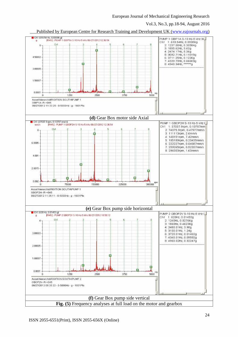
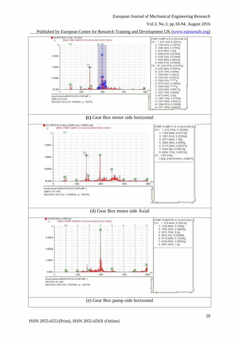
Results of frequency analyses that was done show that the there is an unbalance problem caused
by the electric motor is not perpendicular to the ground or from dust accumulation on the rotor,
and there is an indication to cracked or broken rotor bars or defective or loose rotor bar joints
see Figures (5-a, and 5-b). Also, the gearbox vibration measurement at motor side analysis
shows a problem in the gear teeth could be caused by misalignment or by using bad oil see
Figures (5-c and 5-d). Also, the gearbox vibration measurement at pump side analysis shows
a looseness problem in gear Figures (5-e, and 5-f).

European Journal of Mechanical Engineering Research
Vol.3, No.3, pp.18-94, August 2016
___Published by European Centre for Research Training and Development UK (www.eajournals.org)
23
ISSN 2055-6551(Print), ISSN 2055-656X (Online)
(a) motor non drive side horizontal
(b) motor drive side horizontal
(c) Gear Box motor side horizontal
European Journal of Mechanical Engineering Research
Vol.3, No.3, pp.18-94, August 2016
___Published by European Centre for Research Training and Development UK (www.eajournals.org)
24
ISSN 2055-6551(Print), ISSN 2055-656X (Online)
(d) Gear Box motor side Axial
(e) Gear Box pump side horizontal
(f) Gear Box pump side vertical
Fig. (5) Frequency analyses at full load on the motor and gearbox

European Journal of Mechanical Engineering Research
Vol.3, No.3, pp.18-94, August 2016
___Published by European Centre for Research Training and Development UK (www.eajournals.org)
25
ISSN 2055-6551(Print), ISSN 2055-656X (Online)
Results of vibration measured at no load “Initial state”
Results and analyses for overall vibration and frequency analyses with full load show that high
level of vibration reached to danger level. So, measurements were done for one unit with no
load, as shown in Table [1] and then frequency analysis is done.
From measurements and analyses, the velocity overall vibration level for motor non drive side
at no load are within the acceptable range except the motor non drive side horizontal (MNDSH)
and at the motor non drive side vertical (MNDSV) is in danger and alarm level where it reached
to 16.3 mm/sec, 5.1 mm/sec respectively as shown in Table [1].
Also from measurements and analyses, overall vibration acceleration level for all
measurements for the motor are in the alarm and danger levels where the smallest level is 1.02
g’s and highest level is 2.27 g’s, as shown in Table [1]. From measurements and analyses, the
levels of BDF are within the alarm levels range, where, the level is reached to 8.1 as shown in
Table [1].
Results of frequency analyses that were done at the motor show that the motor misalignment
problem and resonance problems could be caused by weight of the electric motor, as shown in
Figures (6-a, and 6-b).
(a) : motor non drive side horizontal MNDSH
(b) : motor drive side vertical MNDSV
Fig. (6) Frequency analyses at no load on the motor

European Journal of Mechanical Engineering Research
Vol.3, No.3, pp.18-94, August 2016
___Published by European Centre for Research Training and Development UK (www.eajournals.org)
26
ISSN 2055-6551(Print), ISSN 2055-656X (Online)
Results of vibration measured after adding steel supports “First Scenario”
Adding steel supports to motor foundation in the four perpendicular sides and doing
maintenance was done then, overall vibration velocity, gravity acceleration, and bearing defect
factor were done, as shown in Table (2).
From velocity measurements and analyses it’s found that improvement for all overall vibration
levels where level is reached to 8.13 mm/sec at MNDSH with reduction ratio about 50% where
it was 17.6 mm/sec at the initial state, as shown in Table [2], but it’s still danger according to
ISO standard [9] where, the gearbox overall vibration levels are within the acceptable range.
While, From gravity acceleration measurements and analyses, and adding steel supports to
motor foundation it’s found that improvement for all overall vibration levels, but it’s still in the
alarm and danger level where most measurements are higher than 1 g’s where, overall
vibration acceleration is reached to 11.66 g at the GBPSH with reduction ratio 24.77%, but it’s
still danger, as shown in Table [2].
Also, it’s found that improvement for all levels of BDF at the gearbox, where it reached to
6.66, 6.88, and 6.11 at GBMSA, GBPSH, and GBPSV receptively with reduction ratio 22%,
17.77%, and 22.82% receptively but it’s still high and in the alarm level.
Table [2]: Results of vibration measured after adding steel supports “First Scenario”
Overall Bearing defect
Factor Overall Acceleration (g’s) Overall Velocity (mm/s)
Measure
ment
Locatio
ns
Reducti
on Ratio
(%)
First
Scenario
Initial
state
Reducti
on Ratio
(%)
First
Scenar
io
Initial
state
Reducti
on Ratio
(%)
First
Scenar
io
Initial
state
34.63% 3.19 4.88 38.03% 0.88 1.42 53.81% 8.13 17.6 MNDSH
6.31% 3.71 3.96 19.49% 0.95 1.18 36.25% 3.06 4.8 MNDSV
8.22% 3.91 4.26 6.60% 0.99 1.06 -17.50% 1.41 1.2 MNDSA
10.55% 4.58 5.12 3.25% 1.19 1.23 27.33% 1.09 1.5 MDSH
-9.27% 4.95 4.53 9.43% 1.44 1.59 92.80% 0.043 0.597 MDSV
13.97% 5.11 5.94 -25.18% 0.88 0.703 93.07% 0.097 1.4 MDSA
-5.25% 5.81 5.52 18.38% 2.22 2.72 0.96% 3.09 3.12 GBMSH
10.58% 5.24 5.86 12.68% 3.03 3.47 -2.25% 6.35 6.21 GBMSV
13.73% 6.66 7.72 28.77% 5.77 8.1 5.60% 2.19 2.32 GBMSA
22.00% 6.88 8.82 24.77% 11.66 15.5 -7.55% 3.42 3.18 GBPSH
17.77% 6.11 7.43 38.34% 3.57 5.79 4.99% 5.71 6.01 GBPSV
22.82% 4.33 5.61 36.07% 2.18 3.41 -26.57% 1.11 0.877 GBPSA
From frequency analyses, there is frequency equal frequency clutch (GUF) at rotating speed
and its harmonics reached to 6.66 mm /sec as shown in Figures (7-a, 7-b, 7-c, and 7-d). Also,
resonance problem was still found, but less than the previous, as shown in Figure (6-a).

European Journal of Mechanical Engineering Research
Vol.3, No.3, pp.18-94, August 2016
___Published by European Centre for Research Training and Development UK (www.eajournals.org)
27
ISSN 2055-6551(Print), ISSN 2055-656X (Online)
Clutch frequency values appear in the gearbox pump side in the case of full load, which
indicates unbalance problem in the axial direction according to incorrect putting steel
foundation under the motor over the base of concrete, as shown in Figures (7-e and 7-f).
(a) motor non drive side horizontal
(b) motor drive side horizontal
European Journal of Mechanical Engineering Research
Vol.3, No.3, pp.18-94, August 2016
___Published by European Centre for Research Training and Development UK (www.eajournals.org)
28
ISSN 2055-6551(Print), ISSN 2055-656X (Online)
(c) Gear Box motor side horizontal
(d) Gear Box motor side Axial
(e) Gear Box pump side horizontal

European Journal of Mechanical Engineering Research
Vol.3, No.3, pp.18-94, August 2016
___Published by European Centre for Research Training and Development UK (www.eajournals.org)
29
ISSN 2055-6551(Print), ISSN 2055-656X (Online)
(f) Gear Box pump side vertical
Fig. (7) Frequency analyses at full load on the motor and gearbox
Results and discussions after increasing steel supports “Second Scenario”
Measurements were repeated after increasing steel supports to motor foundation in the four
perpendicular sides, are shown in Figure (9). Photo for indicate increasing steel supports to
motor foundation in the four perpendicular sides shown in Figure (9-c). Overall vibration
velocity, gravity acceleration, and bearing defect factor were done. Also, frequency analysis is
done.
(a) Before adding steel
supports
(b) After adding steel
supports
(c) After increasing steel supports
Fig. (9) Photograph for Marashda (1) Pumping Station showing steel supports
Overall Vibration Velocity, acceleration, and BDF were done after increasing steel supports to
motor foundation.

European Journal of Mechanical Engineering Research
Vol.3, No.3, pp.18-94, August 2016
___Published by European Centre for Research Training and Development UK (www.eajournals.org)
30
ISSN 2055-6551(Print), ISSN 2055-656X (Online)
From velocity measurements and analyses it’s found that improvement for all overall vibration
levels and become within the acceptable range where overall vibration level is reached to 1.59
mm/sec at MNDSH with reduction ratio about 90.97 % where it was 17.6 mm/sec at the initial
state and become 8.13 mm/sec with reduction ratio about 53.8% after applying the first
scenario, as shown in Table [2]. Also, the overall vibration levels at gearbox become in the
safe limit where the levels of vibration were reduced with reduction ratio about 40%, as shown
in Table [3]. While it’s found that improvement for all gravity acceleration levels where it
became within the acceptable range, as shown in Table [3]. The highest gravity acceleration
level is reached to 1.47 g’s with reduction ratio reached to 90.52% where it was 15.5 g’s at the
initial state and become 11.66 g’s with reduction ratio about 24.77% after applying the first
scenario, as shown in Table [3].
Also, from measurements, analyses, and after applying the second scenario it’s found that
improvement for all levels of BDF, where the highest level is reached to 4 with reduction ratio
reached to 48.19% where it was 7.72 at the initial state and become 6.66 mm/sec with reduction
ratio about 13.73% after applying the first scenario, as shown in Table [4].
After increasing steel supports to motor foundation stronger than the previous and adding iron
base under the motor foundation so, it become hardness then vibrations decreased on the motor
where it reached to 1.29 mm/sec and 1.1 mm/sec respectively, as shown in Figures (10-a and
10-b). Also resonance problems disappeared and also frequency clutch and its harmonics were
disappeared, as shown in Figures (10-c and 10-d).
Table [3]: Overall Vibration Levels Measured after increasing supports “Second Scenario”
Overall Acceleration (g’s) Overall Velocity (mm/s) Measure
ment
Locatio
ns
Reducti
on Ratio
(%)
Secon
d
Scenar
io
Reducti
on Ratio
(%)
First
Scenar
io
Initia
l
state
Reducti
on Ratio
(%)
Secon
d
Scenar
io
Reducti
on Ratio
(%)
First
Scenar
io
Initial
state
43.66% 0.8 38.03% 0.88 1.42 90.97% 1.59 53.81% 8.13 17.6 MNDSH
61.86% 0.45 19.49% 0.95 1.18 76.46% 1.13 36.25% 3.06 4.8 MNDSV
25.47% 0.79 6.60% 0.99 1.06 -
11.67% 1.34
-
17.50% 1.41 1.2 MNDSA
25.20% 0.92 3.25% 1.19 1.23 50.00% 0.75 27.33% 1.09 1.5 MDSH
40.88% 0.94 9.43% 1.44 1.59 51.42% 0.29 92.80% 0.043 0.597 MDSV
31.72% 0.48 -
25.18% 0.88
0.70
3 74.29% 0.36 93.07% 0.097 1.4 MDSA
63.97% 0.98 18.38% 2.22 2.72 -4.81% 3.27 0.96% 3.09 3.12 GBMSH
70.32% 1.03 12.68% 3.03 3.47 40.42% 3.7 -2.25% 6.35 6.21 GBMSV
90.49% 0.77 28.77% 5.77 8.1 29.74% 1.63 5.60% 2.19 2.32 GBMSA
90.52% 1.47 24.77% 11.66 15.5 3.46% 3.07 -7.55% 3.42 3.18 GBPSH
91.36% 0.5 38.34% 3.57 5.79 45.76% 3.26 4.99% 5.71 6.01 GBPSV
69.79% 1.03 36.07% 2.18 3.41 10.95% 0.781 -
26.57% 1.11 0.877 GBPSA

European Journal of Mechanical Engineering Research
Vol.3, No.3, pp.18-94, August 2016
___Published by European Centre for Research Training and Development UK (www.eajournals.org)
31
ISSN 2055-6551(Print), ISSN 2055-656X (Online)
(a) motor non drive side horizontal
(b) motor drive side horizontal
Table [4]: Overall Vibration Levels Measured after increasing supports “Second Scenario”
Overall Bearing defect Factor (BDF)
Measureme
nt Locations Reduction Ratio
(%)
Second
Scenario
Reduction Ratio
(%)
First
Scenario
Initial
state
42.83% 2.79 34.63% 3.19 4.88 MNDSH
21.21% 3.12 6.31% 3.71 3.96 MNDSV
31.22% 2.93 8.22% 3.91 4.26 MNDSA
17.38% 4.23 10.55% 4.58 5.12 MDSH
27.37% 3.29 -9.27% 4.95 4.53 MDSV
44.11% 3.32 13.97% 5.11 5.94 MDSA
42.75% 3.16 -5.25% 5.81 5.52 GBMSH
44.03% 3.28 10.58% 5.24 5.86 GBMSV
48.19% 4 13.73% 6.66 7.72 GBMSA
56.35% 3.85 22.00% 6.88 8.82 GBPSH
69.99% 2.23 17.77% 6.11 7.43 GBPSV
79.50% 1.15 22.82% 4.33 5.61 GBPSA

European Journal of Mechanical Engineering Research
Vol.3, No.3, pp.18-94, August 2016
___Published by European Centre for Research Training and Development UK (www.eajournals.org)
32
ISSN 2055-6551(Print), ISSN 2055-656X (Online)
(c) Gear Box pump side horizontal
(d) Gear Box pump side vertical
Fig. (10) Frequency analyses at full load on the motor and gearbox after increasing supports
CONCLUSIONS & RECOMMENDATIONS
From initial measurements, vibration levels measured on the pumps are in the danger
level due to weakness of the foundation structure.
Frequency analysis defined the sources of vibration, which easily helped to monitor the
running conditions and solve the problems.
Adding steel supports to motor foundation at two scenarios solved the structure
weakness problem and reduced the high vibration level.
Applying the first scenario by adding steel supports to motor foundation reduced the
overall vibration level 54%, reduced the overall acceleration level 30%, and reduced
the bearing defect factor 20% than the initial state but the problem is still there, and the
vibration level is high.
Applying the second scenario by increasing steel support reduced the overall vibration
level 91%, reduced the overall acceleration level 43%, and reduced the bearing defect
factor 40% than the initial state and solved the structure weakness problem and reduced
the high vibration level to safe limit.
Vertical pump foundation should be carefully designed and strengthened to resist the
dynamic loads.

European Journal of Mechanical Engineering Research
Vol.3, No.3, pp.18-94, August 2016
___Published by European Centre for Research Training and Development UK (www.eajournals.org)
33
ISSN 2055-6551(Print), ISSN 2055-656X (Online)
Inspection and regular maintenance is important to avoid any abnormal conditions
leading to dynamic loads affecting both pump components and foundation.
ACKNOWLEDGMENT
The author wishes thank Mechanical and Electrical Research Institute staff, MERI staff,
for his help measurements on the field. Also, the author wishes thank Mechanical &
Electrical Department for helping to collecting data in the field.
REFERENCES
[1] Smalley, A. J., et al.," Towards Risk Based Criteria for Rotor Vibration”, Proc. of the
Institution of Mech. Engineers, Vibration in Rotating Machinery, pp. 517-527, 1996.
[2] JW. E. (ED) Nelson and J. W. Dufour, "Pump Vibration ", Proceedings of the ninth
international pump users symposium, 1990.
[3] Abdel-Rahman, S. M., et al., “Pump Vibration: Case Studies.”19th International Modal
Analysis Conference (IMAC), Kissimmee, Orlando, Fl., USA, Feb. 2001.
[4] Abdel-Rahman, S. M., "Cavitation Detection in Centrifugal Pumps by Monitoring
Vibration" 1st Int. Conf. On Green & Advanced Technologies, National Research Center,
Cairo, 3-6 Jan. 2004.
[5] William D. Marscher, “AVOIDING FAILURES IN CENTRIFUGAL PUMPS”, Proceedings
of the 19th International Pump Users Symposium, 2014 (Baseplate)
[6] Shamsher Prakash and Vijayk. Puri, “foundations for vibrating machines ", Journal of
Structural Engineering, SERC, Madras. INDIA, Special Issue, April-May 2006.
[7] EBARA, "Ebara Pump System Engineering Handbook", Ebara Corporation, 1997
[8] JAAEE (Japan Assoc. of Ag. Eng. Enterprises), "Pumping Station Eng. Handbook", Japan.
1991.
[9] ISO 10816-1, "Mechanical Vibration – Evaluation of Machine Vibration by Measurements
on Non-Rotating Parts", Part 1, General Guidelines 1995.