Diagnosis of speed sensor faults in an induction machine ...
17
Turk J Elec Eng & Comp Sci (2020) 28: 2821 – 2837 © TÜBİTAK doi:10.3906/elk-1912-126 Turkish Journal of Electrical Engineering & Computer Sciences http://journals.tubitak.gov.tr/elektrik/ Research Article Diagnosis of speed sensor faults in an induction machine based on a robust adaptive super-twisting observer Mohammed Zakaria KARI 1∗ , Abdelkader MECHERNENE 1 , Sidi Mohammed MELIANI 2 , Ibrahim GUENOUNE 3 1 Laboratoire d’Automatique de Tlemcen (LAT), University of Tlemcen, Tlemcen, Algeria 2 Manufacturing Engineering Laboratory of Tlemcen (MELT), University of Tlemcen, Tlemcen, Algeria 3 Inteva Products, Sully Loire, France Received: 20.12.2019 • Accepted/Published Online: 15.05.2020 • Final Version: 25.09.2020 Abstract: The present paper aims to determine a robust sensor fault-tolerant controller based on fuzzy logic using a robust adaptive super-twisting observer for the control of an induction machine and an inverter set by a state estimation method. The speed sensor is considered in the present case. The modular structure of the fault-tolerant control (FTC) scheme allows integrating this sensor within the existing closed-loop system, and the observer can therefore be designed independently. This article presents a new method to develop a fuzzy decision system that provides fault- tolerant control. This paper also aims at detecting the mechanical speed sensor faults. The proposed approach allows the automatic reconfiguration of the system in the event of a speed sensor failure. The defective fuzzy detection system makes a transition between the speed sensor and the robust observer based on a super-twisting algorithm that ensures the continuity and stability of the system; the fuzzy detection and transition system is required to be robust to parametric variations, and must be fast enough in order to locate the defect and eventually make a transition in the event of a fault. The output of the fuzzy block is injected into the control block to ensure super-twisting speed regulation. The performance of the proposed strategy also the robustness against parameter variation are assessed by simulation thanks to Matlab/Simulink software. Key words: Sensorless control, fuzzy supervisor, fault detection and isolation, Liyaponov theory, induction machine 1. Introduction Nowadays, mastery of risks and operational safety occupies an important place in automated industrial systems. However, this operational safety can unfortunately be hampered by some malfunctions that may occur within the system; these misfunctions can be attributed to the complexity of that system, particularly in relation with the field control part [1]. When dealing with this issue, the manufacturers are required to develop an effective technicality of monitoring a system that should be equipped with a suitable diagnostic tool in order to detect, identify, locate, and isolate any fault that is responsible for a malfunction within a system. This helps to prevent the propagation of the problem and to limit the bad consequences that could arise from that defect; it can certainly ensure the safety of people and improve the reliability and availability of their production tools [2]. To this end, and in order to provide online monitoring of these processes. Several recent methods of faults diagnostic for induction motor have been developed (see for example [3–6]). The literature shows a great diversity of methods from different points of view. Hardware redundancy has often been used in the past but ∗ Correspondence: [email protected] This work is licensed under a Creative Commons Attribution 4.0 International License. 2821
Transcript of Diagnosis of speed sensor faults in an induction machine ...
Turk J Elec Eng & Comp Sci(2020) 28: 2821 – 2837© TÜBİTAKdoi:10.3906/elk-1912-126
Turkish Journal of Electrical Engineering & Computer Sciences
http :// journa l s . tub i tak .gov . t r/e lektr ik/
Research Article
Diagnosis of speed sensor faults in an induction machine based on a robustadaptive super-twisting observer
Mohammed Zakaria KARI1∗, Abdelkader MECHERNENE1, Sidi Mohammed MELIANI2,Ibrahim GUENOUNE3
1Laboratoire d’Automatique de Tlemcen (LAT), University of Tlemcen, Tlemcen, Algeria2Manufacturing Engineering Laboratory of Tlemcen (MELT), University of Tlemcen, Tlemcen, Algeria
3Inteva Products, Sully Loire, France
Received: 20.12.2019 • Accepted/Published Online: 15.05.2020 • Final Version: 25.09.2020
Abstract: The present paper aims to determine a robust sensor fault-tolerant controller based on fuzzy logic using arobust adaptive super-twisting observer for the control of an induction machine and an inverter set by a state estimationmethod. The speed sensor is considered in the present case. The modular structure of the fault-tolerant control(FTC) scheme allows integrating this sensor within the existing closed-loop system, and the observer can therefore bedesigned independently. This article presents a new method to develop a fuzzy decision system that provides fault-tolerant control. This paper also aims at detecting the mechanical speed sensor faults. The proposed approach allowsthe automatic reconfiguration of the system in the event of a speed sensor failure. The defective fuzzy detection systemmakes a transition between the speed sensor and the robust observer based on a super-twisting algorithm that ensures thecontinuity and stability of the system; the fuzzy detection and transition system is required to be robust to parametricvariations, and must be fast enough in order to locate the defect and eventually make a transition in the event of afault. The output of the fuzzy block is injected into the control block to ensure super-twisting speed regulation. Theperformance of the proposed strategy also the robustness against parameter variation are assessed by simulation thanksto Matlab/Simulink software.
Key words: Sensorless control, fuzzy supervisor, fault detection and isolation, Liyaponov theory, induction machine
1. IntroductionNowadays, mastery of risks and operational safety occupies an important place in automated industrial systems.However, this operational safety can unfortunately be hampered by some malfunctions that may occur withinthe system; these misfunctions can be attributed to the complexity of that system, particularly in relationwith the field control part [1]. When dealing with this issue, the manufacturers are required to develop aneffective technicality of monitoring a system that should be equipped with a suitable diagnostic tool in orderto detect, identify, locate, and isolate any fault that is responsible for a malfunction within a system. Thishelps to prevent the propagation of the problem and to limit the bad consequences that could arise from thatdefect; it can certainly ensure the safety of people and improve the reliability and availability of their productiontools [2]. To this end, and in order to provide online monitoring of these processes. Several recent methods offaults diagnostic for induction motor have been developed (see for example [3–6]). The literature shows a greatdiversity of methods from different points of view. Hardware redundancy has often been used in the past but∗Correspondence: [email protected]
This work is licensed under a Creative Commons Attribution 4.0 International License.2821
KARI et al./Turk J Elec Eng & Comp Sci
this generally adds complexity to the design of the system and increases its cost price. Despite the overhead ofthe computing time, software redundancy has become a promising alternative to hardware redundancy [1, 7].This can be an interesting and efficient solution to this problem because it is flexible and has the capacityto evolve. Estimating the conditions or parameters of the system appears to be an appropriate and efficienttool for fault-tolerant control (FTC). Moreover, this approach is commonly recommended for the detection ofdefects because it induces only a very short delay in the decision-making process [7]. Its main advantage liesin its capacity to detect partial defects as compared to traditional methods which can only find the failure ofthe entire sensor. More specifically, this method allows for a quick detection of various types of faults, such aspolarization, saturation, or complete disconnection of the system. Recently, analytical methods have becomeincreasingly important; they have been widely used especially in the context of critical applications such asthe energy systems, transport systems and industry. These methods have evolved considerably since theirintroduction. Using an analytical model helps better know and understand the system. The basic principleconsists of collecting information on the process to be monitored, using sensors [8–10]. Comparing the actualbehavior and the predicted one using the suggested model provides information that is contained in a setof defect indicator signals (residues). The temporal analysis or frequency analysis of these signals makes itpossible to detect and interpret any abnormal behavior of the system in order to locate the origin of the failure.Many researchers have repeatedly proposed to exploit these techniques, and particularly those addressing linearmodels, by adapting electrotechnical applications. It is worth reminding that an electrotechnical system hastwo interesting peculiarities; first, it can be decomposed into several subsystems linked together, and second,the models used in these systems are generally linear; if they are not, they can be linearized. Studying thepossible drawbacks and trying to find the appropriate solutions to the problem is a necessity in order to achievegood fault tolerant control architecture [10–12].
Furthermore, artificial intelligence techniques generally confer the capacity and power needed in solvingthe different problems encountered in the field of industrial systems, particularly those related to the controlof electrical machines. It has been observed that using fuzzy logic represents one of the most interesting routesfor the implementation of the core of the proposed fault-tolerant control (FTC) [2, 13].A new fuzzy supervisor for fault-tolerant speed sensor for induction motors controlled by super-twisting isdesigned in this article. The super-twisting procedure uses the same sliding-mode. In addition, it has a finite-time convergence and is less chattering as compared to the other procedure. The function of a fuzzy supervisoris to allow a transition of the system. When a fault is detected in the speed sensor, to the rotor speed whichis estimated by the adaptive super-twisting observer which in turn guarantees the continuity of the system.The system must be robust to parametric variation; it must not make any transition in case of any change inparameters and is required to be fast enough in order to detect and locate the fault and then make a transitionto the speed given by the observer in the sliding mode. The paper is organized as follows. In Section 2, themathematical models of the induction motor (IM) are first presented in the reference frame, rotating at thesynchronous speed, and then in the stationary stator reference frame. Section 3 describes the principle of rotorflux orientation; the theory of super-twisting sliding modes and its application to induction motor control arealso developed. Section 4 introduces the concepts of adaptive super-twisting speed and rotor flux observer.Section 5 describes the fuzzy detection and reconfiguration system proposed in this paper. In Section 6, somesimulation results related to the performance of the suggested strategy of fault-tolerant control (FTC) associatedwith motor control are presented and discussed. Finally, Section 7 provides some comments and then gives afinal conclusion.
2822
KARI et al./Turk J Elec Eng & Comp Sci
The main objective of this work is to propose a robust and reliable detection and reconfiguration system for thedetection of a speed sensor defect. The main contributions are:
• A robust proposed observer which guarantees a good estimate of the rotor speed in different areas especiallyat low speed (area of nonobservability);
• The fuzzy detection and reconfiguration system that guarantees the continuity of the system in presenceof the several disturbances (fault, parameter variation).
The results of simulations presented in this paper clearly show these contributions.
2. Mathematical modeling of IM
2.1. Modeling of IM in the (d-q) reference frame
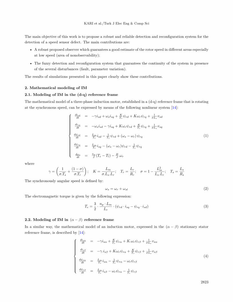
The mathematical model of a three-phase induction motor, established in a (d-q) reference frame that is rotatingat the synchronous speed, can be expressed by means of the following nonlinear system [14]:
disddt = −γisd + ωsisq +
KTrψrd +Kωrψrq +
1σLs
vsd
disqdt = −ωsisd − γisq +Kωrψrd +
KTrψrq +
1σLs
vsq
dψrd
dt = Lm
Trisd − 1
Trψrd + (ωs − ωr)ψrq
dψrq
dt = Lm
Trisq − (ωs − ωr)ψrd − 1
Trψrq
dωr
dt =np
J (Te − Tl)− BJ .ωr
(1)
where
γ =
(1
σ.Ts+
(1− σ)
σ.Tr
); K =
Lmσ.Ls.Lr
; Tr =LrRr
; σ = 1− L2m
Ls.Lr; Ts =
LsRs
The synchronously angular speed is defined by:
ωs = ωr + ωsl (2)
The electromagnetic torque is given by the following expression:
Te =3
2· np · Lm
Lr· (ψrd · isq − ψrq · isd) (3)
2.2. Modeling of IM in (α− β) reference frame
In a similar way, the mathematical model of an induction motor, expressed in the (α − β) stationary statorreference frame, is described by [14]:
disαdt = −γisα + K
Trψrα +K.ωrψrβ + 1
σLsvsα
disβdt = −γ.isβ +Kωrψrα + K
Trψrβ + 1
σLsvsβ
dψrα
dt = Lm
Trisα − 1
Trψrα − ωrψrβ
dψrβ
dt = Lm
Trisβ − ωrψrα − 1
Trψrβ
(4)
2823

KARI et al./Turk J Elec Eng & Comp Sci
3. Sliding mode control for IM3.1. Rotor flux orientationThe entire control strategy depends on the correctness of the calibration of the reference frame (d-q), and thuson knowing the value of the angle of Park [14, 15].
ψrq = 0 =⇒ ψr = ψrd (5)
By imposing ψrq = 0 , the model (1) becomes:
disddt
disqdt
=
[−γisd + ωsisq +
KTrψr
−ωsisd − γisq +Kωrψr
]+
[ 1σLs
0
0 1σLs
] [vsdvsq
](6)
and ψr
dt = Lm
Tr.isd − 1
Tr.ψr
ωsl =Lm
Tr.ψr.iqs
dωr
dt = 32 · n
2p·Lm
Lr· ψr.isq − np
J · Tl − BJ .ωr
(7)
After passing through Laplace transformation, we obtain expressions:ψr =
Lm
1+Trsisd
Te =32 · np·Lm
Lr.ψrisq
(8)
where the permanent regime is established. The procedure consists of solving numerically the following equation[14]:
dθsdt
= ωr +LmisqTrψr
(9)
In steady state, Equation (8) gives ψr = Lm.isd . Thus, Equation (9) becomes:
dθsdt
= ωr +isqTrisd
(10)
3.2. Super-twisting controlThe super-twisting algorithm is part of sliding mode control. It is particularly used in second-order slidingmodes. This algorithm was originally proposed by Levant [16] in the case where the system has a relativedegree equal to 1 with respect to the sliding variable, called S. This algorithm was developed while preservingthe main advantages of first-order sliding modes (robustness, convergence in finite time). It has the greatadvantage of eliminating chattering. The control law of the super-twisting algorithm [11, 16] may be expressedas:
U = V1(t) + V2(t) (11)
with V1(t) = −K1 | S |r sign(S)V2(t) = −K2
∫sign(S)
(12)
2824
KARI et al./Turk J Elec Eng & Comp Sci
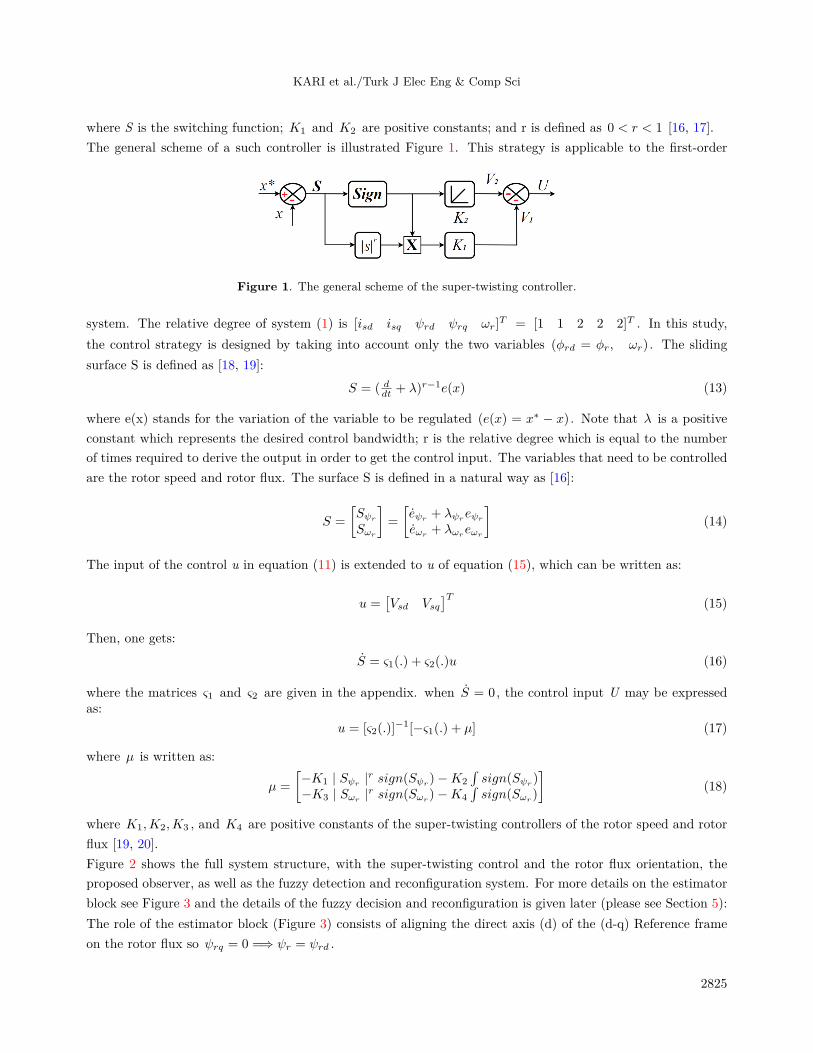
where S is the switching function; K1 and K2 are positive constants; and r is defined as 0 < r < 1 [16, 17].The general scheme of a such controller is illustrated Figure 1. This strategy is applicable to the first-order
Figure 1. The general scheme of the super-twisting controller.
system. The relative degree of system (1) is [isd isq ψrd ψrq ωr]T = [1 1 2 2 2]T . In this study,
the control strategy is designed by taking into account only the two variables (ϕrd = ϕr, ωr) . The slidingsurface S is defined as [18, 19]:
S = ( ddt + λ)r−1e(x) (13)
where e(x) stands for the variation of the variable to be regulated (e(x) = x∗ − x) . Note that λ is a positiveconstant which represents the desired control bandwidth; r is the relative degree which is equal to the numberof times required to derive the output in order to get the control input. The variables that need to be controlledare the rotor speed and rotor flux. The surface S is defined in a natural way as [16]:
S =
[Sψr
Sωr
]=
[eψr
+ λψreψr
eωr+ λωr
eωr
](14)
The input of the control u in equation (11) is extended to u of equation (15), which can be written as:
u =[Vsd Vsq
]T (15)
Then, one gets:S = ς1(.) + ς2(.)u (16)
where the matrices ς1 and ς2 are given in the appendix. when S = 0 , the control input U may be expressedas:
u = [ς2(.)]−1[−ς1(.) + µ] (17)
where µ is written as:
µ =
[−K1 | Sψr
|r sign(Sψr)−K2
∫sign(Sψr
)−K3 | Sωr |r sign(Sωr )−K4
∫sign(Sωr )
](18)
where K1,K2,K3 , and K4 are positive constants of the super-twisting controllers of the rotor speed and rotorflux [19, 20].Figure 2 shows the full system structure, with the super-twisting control and the rotor flux orientation, theproposed observer, as well as the fuzzy detection and reconfiguration system. For more details on the estimatorblock see Figure 3 and the details of the fuzzy decision and reconfiguration is given later (please see Section 5):The role of the estimator block (Figure 3) consists of aligning the direct axis (d) of the (d-q) Reference frameon the rotor flux so ψrq = 0 =⇒ ψr = ψrd .
2825

KARI et al./Turk J Elec Eng & Comp Sci
Figure 2. Block diagram of the IM drive system with the proposed sensor fault detection and reconfiguration system.
Figure 3. Block diagram of Park angle and rotor flux estimator.
4. Model of the rotor speed observer
The observer proposed in this article is a new hybrid observer close to the sliding observer; its role is to estimatethe rotor fluxes in the stationary frame of reference (α − β) while ensuring the convergence of the observer ofthe current in the same reference frame. Once the flux values are found, they are used in the adaptive observerand the super-twisted sliding mode observer in order to estimate rotor speed. The approach used here is welldetailed in what follows. For clarity, model (4) can be written as [21]:
disαdt = −γisα + K
Trψrα −Kωrψrβ + 1
σLsvsα +KcSiα +Kvsign(Siα)
disβdt = −γ.isβ +Kωrψrα + K
Trψrβ + 1
σLsvsβ +KcSiβ +Kvsign(Siβ)
dψrα
dt = Lm
Trisα − 1
Trψrα − ωrψrβ +Kψsign(Siα)
dψrβ
dt = Lm
Trisβ − ωrψrα − 1
Trψrβ +Kψsign(Siβ)
(19)
2826
KARI et al./Turk J Elec Eng & Comp Sci
Where
[SiαSiβ
]=
[eisαeisβ
]=
[isα − isαisβ − isβ
](20)
Sisα,βare sliding mode surfaces and Kc , Kv , and Kψ are the observer gains. The convergence of the estimated
currents isα and isβ towards the real stator currents isα and isβ makes it possible to estimate the rotor fluxes
ψrα and ψrβ which allow evaluating the rotor speed with the adaptive observer using a super-twisting-basedstrategy [21].
4.1. Observer based on adaptive super-twisting strategy4.1.1. Adaptive observerThe speed estimation method using an adaptive observer is an approach known for the simplicity of its algorithm,its stability, and rapid convergence, as well as for its performance in terms of accuracy in a fairly wide speedrange. The adaptation law obtained to ensure the convergence of ωr to ωr is of type proportional-integral; itis expressed by means of the following relation [22]:
ωr = Kp(eisα ψrβ − eisβ ψrα)−Ki
∫(eisα ψrβ − eisβ ψrα) (21)
with Kp , Ki are respectively the proportional and integral gains and
[eisαeisβ
]=
[isα − isαisβ − isβ
]The main disadvantage of this technique is that the estimate is less accurate at low speeds. For this reason itwas decided to use the super-twisting technique [22, 23].
4.1.2. Adaptive super-twisting observerIn this section, the PI regulator is replaced by a super-twisting controller in order to guarantee a better estimationof the rotor speed over all low speeds. The super-twisting algorithm does not require any information on thevalue of s (and hence its great practical interest) while retaining good robustness properties. The control lawusing the super-twisting algorithm may therefore be written just like equation (11) [16, 19, 24]. Consequently:
U = V1(t) + V2(t) (22)
with V1(t) = −λi | S |r sign(S)V2(t) = −λp
∫sign(S)
(23)
whereS = eisα ψrβ − eisβ ψrα (24)
Thus,
ωr = −λi | S |r sign(S)− λp
∫sign(S) (25)
2827

KARI et al./Turk J Elec Eng & Comp Sci
5. Speed sensor fault tolerant controlThis section focuses on the fault-tolerant control method that relies on the speed estimate obtained by meansof the suggested adaptive super-twisting observer. The measured and estimated speeds are fed into the fuzzydetection and decision unit in order to detect and reconfigure the faulty speed sensor based on the estimatedspeed [11, 25]. The estimation of speed is not influenced by the speed sensor fault. For fault identification, itis reasonable to write:
eωr = ωr − ωr (26)
5.1. Fuzzy detection and decision systemThe fault-tolerant control system is displayed in Figure 4. The fault in our case results from a speed sensorfailure. The transition of the command by super-twisting, using the speed sensor, towards the adaptive super-twisting observer (sensorless control) must ensure the continuity of operation of the system, which in turnguarantees the continuity of the IM control.The basic idea is to develop a transition block capable of generating a transition function UTr ; this function isdefined as a linear combination of the speed measured by the sensor and the speed delivered by the proposedobserver.
UTr = (1− Fs)ωr + Fsωr (27)
-Fs : Transition function obtained from the block based on fuzzy logic.-Fs= 0 there is no problem.-Fs = 1 there is a problem.
Figure 4. Architecture of the fault-tolerant controller.
5.1.1. Fuzzy decision block designThe fuzzy decision block receives the two input variables, e and de, and delivers the output variables Fs :
eωr = ωr − ωrdeωr
dt = ddt (ωr − ωr)
(28)
5.1.2. Fuzzy rules extraction
A Mamdani-type fuzzy implementation using a max-min inference was chosen. The membership functionsdescribe the variable along a normalized universe of discourse. The fuzzy variables can be negative great (NG),close to zero (Z), and positive great (PG), as can be seen in Figure 5 [2, 13]. To make things clearer, some rulesare described below:
2828

KARI et al./Turk J Elec Eng & Comp Sci
NG
-1000 10000 -10 100 0 Fs1
Z PG
deωr eωr
NG Z PG GF
Figure 5. Distribution of membership functions of the input/output variables: Left-function of speed error derivative.Middle-function of speed error. Right-function of fault detector.
- If (eωr is NG or PG) and (deωr is NG or PG), then (Fs is F). The extracted rule suggests that in the casewhere ΔIs and the error on the speed are negative great (NG) or positive great (PG), then the quantity Fs(fault detector) is equal to F in this case, and the observer is selected. Therefore, a failure in the speed sensorengenders a transition.-If (eωr is Z) and (deωr is Z), then (Fs is G). In this case, no transition is made, which indicates that thespeed sensor is working properly.-If (eωr is Z) and (deωr is PG), then (Fs is G). In this case, no transition is made since the information onthe speed (e null) indicates that the speed sensor is working properly.
6. Simulation resultsIn order to test the validity of the controller, simulations were implemented by means of the Matlab / Simulinksoftware package, for a sample time step T = 10−5 s. It is important to mention that the nominal model of theinduction motor and all the constraints to which it is subjected were taken into account. First, the actuatorfaults are introduced at t = 2s , and then the fault-tolerant control, with and without the load torque, is studied.It should be noted that the defect may be the result of a cable break, which means that no information can beobtained from the rotor speed sensor. The results obtained are presented in the following figures. In order toassess the performance and robustness of the speed sensor fault detection method, it was decided to conductthe following two scenarios:1- Appearance of speed sensor defect at no load.2- Appearance of speed sensor defect with load torque.The benchmark was chosen to test the reaction of the fuzzy decision and reconfiguration block at high speedsand reverse speeds.
6.1. Scenario 1This scenario was devised to see the performance of the system without the application of the load torque butin the presence of the speed sensor fault, as shown in Figure 6.
Figure 6 presents the simulation results of the induction machine under super-twisting control, with adefect on the speed sensor at t = 2 s. It is expected to find the rotor flux at t = 0.2 s, for the zero referencespeed (ω∗
r =) . Moreover, it is important to note that after a reference change from 0 to 120 rad/s and a reversalof the speed to –120 rad/s at t = 3 s, the rotor speed r responds very quickly, thanks to the properties ofsuper-twisting control; in this case, the convergence occurs in a finite time. When the fuzzy decision systemdetects the fault, the speed sensor fault (Fs = 1) is observed at t = 2 s. The transition to the adaptive
2829

KARI et al./Turk J Elec Eng & Comp Sci
Figure 6. Performance of speed sensor fault tolerant control at no load- Top-left- Rotor speed (rad/s) versus time(s). Top-right- Estimated and measured rotor speed (rad/s) versus time (s). Middle-left- Error of speed estimation(rad/s) versus time (s). Middle-Right- Rotor flux (Wb) nad transition function versus time (s). Bottom-left- Statorcurrents in d-q axis (A) versus time (s). Bottom-Right- Electromagnetic torque (Nm) versus time (s).
super-twisting observer ensures a very good continuity of service of the system thanks to a good estimation ofthe rotor speed and rotor flux. It can clearly be seen that the difference between the reference speed (ω∗
r ) andthe controlled speed (ωr) is negligible even at the appearance of the default. The current (isd) is not perturbedby the large changes in the current (isq) . Therefore, the simulation proves the presence of a decoupling of thevector control. Moreover, there is a small noise in the current (isq) when the defect appears and this is certainlydue to the chattering that exists in the estimated speed by the proposed observer. The electromagnetic torque(Te) is almost zero because there is no applied load torque except there is noise when the speed sensor faultoccurs. The electromagnetic torque is the image of the stator current (isq) .
6.2. Scenario 2It is the same test as the previous scenario but with the application of the load torque to see the reactionof the detection and reconfiguration system. When the same benchmark is used along with an application ofthe load torque at t = 1 s, the results of the simulation in Figure 7 are found identical to those in Figure 6.
2830

KARI et al./Turk J Elec Eng & Comp Sci
The only difference is that there is an increase in the stator current (isq) and the electromagnetic torque (Te)
because a load torque is applied at t = [1, 4]s so there is the call of the satator current (isq) . The fuzzy failuredetection and reconfiguration block does not give false alarms, despite the application of the load torque. Onthe other hand, with the appearance of the speed sensor fault (Fs = 1) at t = 2 s, the transition to the adaptivesuper-twisting observer gives very good results while ensuring the continuity of service of the system.
Figure 7. Performance of speed sensor fault-tolerant control with load torque. Top-left- Rotor speed (rad/s) versus time(s). Top-right- Estimated and measured rotor speed (rad/s) versus time (s). Middle-left- Error of speed estimation(rad/s) versus time (s). Middle-Right- Rotor flux (Wb) nad transition function versus time (s). Bottom-left- Statorcurrents in d-q axis (A) versus time (s). Bottom-Right- Electromagnetic torque (Nm) versus time (s).
6.3. Scenario 3In order to demonstrate the effectiveness and the reaction of the proposed system in this paper at low speedand in the nonobservability zone (ωs = 0) , we choose this benchmark with the presence of the speed sensorfault at t = 2 s, the fault in this case, and with the sensor giving false information. In addition, we applied aload torque at t = [1, 4] s and we got these results: Figure 8 shows the performance of the proposed systemat low speed and in the nonobservability zone. The rotor speed correctly follows its reference even with theappearance of the fault at t = 2 s so Fs = 1 and application of a load torque of Tl = 8 Nm at t = [1, 4] s, and
2831

KARI et al./Turk J Elec Eng & Comp Sci
the error of the rotor speed is negligible (eωr) . The estimated flux (ψr) follows its reference (ψ∗r ) and this is
thanks to the proposed observer. A little noise on the (isq) current is seen when the fault appears and evenon the electromagnetic torque (Te ) because of the information on the rotor speed provided by the observer is alittle noisy (area of nonobservability). The results presented in this scenario show very well the reliability androbustness of the system and this is thanks to the robustness of the observer and the system of detection andreconfiguration proposed in this paper.
Figure 8. Performance of speed sensor fault-tolerant control with load torque at low speed. Top-left- Rotor speed(rad/s) versus time (s). Top-right- Estimated and measured rotor speed (rad/s) versus time (s). Middle-left- Errorof speed estimation (rad/s) versus time (s). Middle-Right- Rotor flux (Wb) nad transition function versus time (s).Bottom-left- Stator currents in d-q axis (A) versus time (s). Bottom-Right- Electromagnetic torque (Nm) versustime (s).
6.4. Scenario 4Robustness tests were carried out in order to examine the reaction and robustness of the fuzzy supervisor andthe proposed reconfiguration system. The values of resistances Rs and Rr were varied in the tests, while a loadtorque was applied; the default appeared at t = 2 s. The values of resistances Rs and Rr were appropriatelychosen because the variation of Rs influences the controller and the variation of Rr influences the observer.
2832
KARI et al./Turk J Elec Eng & Comp Sci
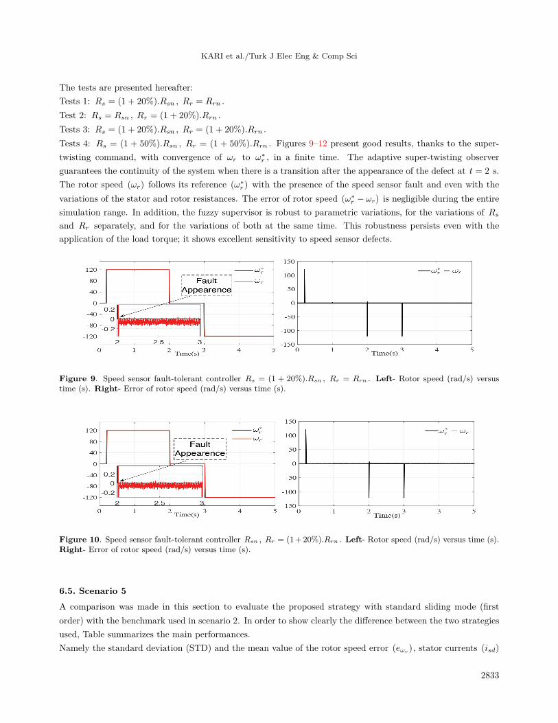
The tests are presented hereafter:Tests 1: Rs = (1 + 20%).Rsn , Rr = Rrn .Test 2: Rs = Rsn , Rr = (1 + 20%).Rrn .Tests 3: Rs = (1 + 20%).Rsn , Rr = (1 + 20%).Rrn .Tests 4: Rs = (1 + 50%).Rsn , Rr = (1 + 50%).Rrn . Figures 9–12 present good results, thanks to the super-twisting command, with convergence of ωr to ω∗
r , in a finite time. The adaptive super-twisting observerguarantees the continuity of the system when there is a transition after the appearance of the defect at t = 2 s.The rotor speed (ωr) follows its reference (ω∗
r ) with the presence of the speed sensor fault and even with thevariations of the stator and rotor resistances. The error of rotor speed (ω∗
r − ωr) is negligible during the entiresimulation range. In addition, the fuzzy supervisor is robust to parametric variations, for the variations of Rsand Rr separately, and for the variations of both at the same time. This robustness persists even with theapplication of the load torque; it shows excellent sensitivity to speed sensor defects.
Figure 9. Speed sensor fault-tolerant controller Rs = (1 + 20%).Rsn , Rr = Rrn . Left- Rotor speed (rad/s) versustime (s). Right- Error of rotor speed (rad/s) versus time (s).
Figure 10. Speed sensor fault-tolerant controller Rsn , Rr = (1+20%).Rrn . Left- Rotor speed (rad/s) versus time (s).Right- Error of rotor speed (rad/s) versus time (s).
6.5. Scenario 5A comparison was made in this section to evaluate the proposed strategy with standard sliding mode (firstorder) with the benchmark used in scenario 2. In order to show clearly the difference between the two strategiesused, Table summarizes the main performances.Namely the standard deviation (STD) and the mean value of the rotor speed error (eωr
) , stator currents (isd)
2833

KARI et al./Turk J Elec Eng & Comp Sci
Figure 11. Speed sensor fault tolerant controller Rs = (1+20%).Rsn , Rr = (1+20%).Rrn . Left- Rotor speed (rad/s)versus time (s). Right- Error of rotor speed (rad/s) versus time (s).
Figure 12. Speed sensor fault tolerant controller Rs = (1+50%).Rsn , Rr = (1+50%).Rrn . Left- Rotor speed (rad/s)versus time (s). Right- Error of rotor speed (rad/s) versus time (s).
and (isq) , and electromagnetic torque (Te) . It should be noted that these indicators were collected over theentire simulation range.
Table . Performance comparison of the controllers.
Control strategy Strategy 1 Strategy 2 Evaluation Strategy 2/Strategy 1STD eωr (rad/s) 5.3953 3.6428 –32.49%STD isd (A) 0.4311 0.2763 –35.91%STD isq (A) 2.6648 2.3931 –9.51%STD Te (Nm) 4.5335 4.1029 –9.5%mean eωr
(rad/s) 1.8670 0.2387 –87.22%mean isd (A) 1.3935 1.3877 –0.42%mean isq (A) 3.1759 2.9369 –7.53%mean Te (Nm) 7.1589 5.0337 –29.69%
As explaned below, the STD and the mean values are calculated for the proposed method and thestandard sliding mode. For a such comparison, the following notations will be used:
• Strategy 1 = standard sliding mode controller + adaptive standard sliding mode observer.
• Strategy 2 (proposed method) = super twisting controller + adaptive super twisting observer.
2834
KARI et al./Turk J Elec Eng & Comp Sci
The STD of the variables are lower for Strategy 2 (proposed method). The reduction is significant −32.49% forerror of rotor speed eωr , −35.91% for the stator current isd . Concerning the mean value there is a significantreduction for error of rotor speed eωr −87.22% , −29.69% for electromagnetic torque Te . This last can beconsidered an indication for reducing the torque oscillations. The results show very well the advantage of theproposed method.
7. ConclusionThe present paper proposes a new sensor fault detection and isolation system with a reconfiguration algorithmfor an induction motor based on a robust adaptive super-twisting observer. It is intended to maintain continuoussystem operation. Simulation results are presented to highlight the performance of the proposed approach andto show the robustness of the fuzzy supervisor to the parametric variations. The suggested method shows agreat sensitivity in the event of a defect in the speed sensor. This is the main purpose of the detection andreconfiguration system proposed here. The proposed strategy (control+ observer) is compared to a standardsliding mode (control + observer), by considering the scenario 2, through some performance indicators asstandard deviation and mean values. As future work, the authors will concentrate on the stability study inclosed loop of the full system. An important next step will concern the experimental tests of the proposedstrategy by taking into account the low-speed and zero-speed areas.
AppendixMotor parametersRated values:
1.5 kW, 220/380 V, 6.3/3.5 A, 50 Hz, 2 poles, 1430 rpmRated parameters:Rs=5.72 Ω , Rr=4.2 Ω , Ls=0.462 H, Lr=0.462 H, Lm=0.440 H, J=0.049 kg m2 , B=0.003 kg m/s.
NomenclatureThe matrices ξ1(.) and ξ2(.) are read as:
ξ1 =
[ψr
∗+ λψr
ψr∗+ a1ψr + a2isd − a3isq − a4ψr
ωr∗ + λωr
ωr∗ + a5ωr + a6ωsisd + (a7 + a10)isq + a8ωr − a9isdisq
]; ξ2 =
Lm
TrσLs
KσLs
ψr
where
a1 =1
Tr− λψr
; a2 =Lmγ
Tr; a3 =
LmωsTr
; a4 =LmK
T 2r
; a5 =BnpJ
− λωr
a6 = Kψr; a7 = a6λ; a8 = a6ψrB; a9 = a4Tr; a10 =a6Tr
2835

KARI et al./Turk J Elec Eng & Comp Sci
r , s subscripts for rotor and statord , q subscripts for d and q axisα , β subscripts for α and β axisn subscript for nominal valueV ,i voltage and currentψ , ψrn flux and nominal value of rotor fluxRs , Rr stator and rotor resistancesLm mutual inductanceLs , Lr stator and rotor inductancesTs , Tr stator and rotor time constantσ total leakage factorJ moment of inertiaB friction coefficientnp number of pole pairsTe electromagnetic torqueTl load torqueθs position of rotor fluxωr electrical angular rotor speedωs synchronously rotating angular speedωsl slip rotating angular speedΩr rotor mechanical angular speedω∗r , ωrmes reference and musured rotor speedsωr, ψr estimated rotor speed and estimated rotor fluxψ, ψ∗ flux and its reference
Acknowledgment
The authors wish to thank the managers and members of the “Laboratoire d’Automatique de Tlemcen (LAT)”at the University of Tlemcen in Algeria for their precious remarks and suggestions and we thank the DGRSDTfor their support.
References
[1] Benbouzid MEH, Diallo D, Zeraoulia M. Advanced fault tolerant control of induction-motor drives for EV/HEVTraction Applications. IEEE Transactions 2007; 56 (2): 519- 528. doi: 10.1109/TVT.2006.889579
[2] Baghli L, Poure P, Rezzoug A. Sensor fault detection for fault tolerant vector controlled induction machine. In:European Conference on Power Electronics and Applications, IEEE Energy Conversion Congress and Applications;Dresden, Germany; 2005; pp. 1-10.
[3] Gundewar SK, Kane PV. Fuzzy FMEA analysis of induction motor and overview of diagnostic techniques toreduce risk of failure. Reliability, Safety and Hazard Assessment for Risk-Based Technologies 2020; 1: 927-939. doi:10.1007/978-981-13-9008-1_78
[4] Ali MZ, Shabbir MNSK, Kawsar Zaman SM, Liang X. Single- and multi-fault diagnosis using machine learningfor variable frequency drive-fed induction motors. IEEE Transactions on Industry Applications 2020; 1: 1-20. doi:10.1109/TIA.2020.2974151
[5] Hajary A, Kianinezhad R, Seifossadat SG, Mortazavi SS, Saffarian A. Detection and localization of open-phasefault in three-phase induction motor drives using second order rotational park transformation. IEEE Transactionson Power Electronics 2019; 34 (11): 11241-11252. doi: 10.1109/TPEL.2019.2901598
[6] Yetgin MG. Effects of induction motor end ring faults on motor performance. Experimental results. EngineeringFailure Analysis 2019; (96): 374-383. doi: 10.1016/j.engfailanal.2018.10.019
2836

KARI et al./Turk J Elec Eng & Comp Sci
[7] Pilloni A, Pisano A, Usai E. Robust FDI in induction motors via second order sliding mode technique. In: 12thIEEE Workshop on Variable Structure Systems; Mumbai, India; 2012. pp. 467- 472.
[8] Diao S, Diallo D, Makni Z, Marchand C. Diagnostic des capteurs pour la commande des entrainements électriques.In: Symposium de G´enie Electrique (SGE’14) : EF-EPF-MGE 2014; ENS Cachan, France; 2014. pp.1-20 (inFrench).
[9] Najafabadi TA, Salmasi FR, Jabehdar MP. Detection and isolation of speed-, DC-link voltage-, and current-sensorfaults based on an adaptive observer in induction motor drives. IEEE Transactions on Industrial Electronics 2011;58 (5): 1662-1672. doi: 10.1109/TIE.2010.2055775
[10] Krishna M, Daya F. Luenberger observer-based sensor fault detection: online application to DC motor. TurkishJournal of Electrical Engineering & Computer Sciences 2014; 22 (2): 363-370. doi: 10.3906/elk-1203-84
[11] Kommuri SK, Veluvolu KC, Defoort M. Second-order sliding mode based sensor fault-tolerant control of inductionmotor drives. In: International Conference on Industrial Instrumentation and Control (ICIC)College of Engineering;Pune, India; 2015. pp.1-20.
[12] Ortaç Kabaoglu R. A fault detection, diagnosis, and reconfiguration method via support vector machines. TurkishJournal of Electrical Engineering & Computer Sciences 2015; 23 (2): 589-601. doi: 10.3906/elk-1301-96
[13] Omaç Z. Fuzzy-logic-based robust speed control of switched reluctance motor for low and high speeds. TurkishJournal of Electrical Engineering & Computer Sciences 2019; 27 (1): 316-329. doi: 10.3906/elk-1712-186
[14] Vas P. Vector Control of AC Machines. USA: Oxford University Press, 1990
[15] Saleem A, Soliman H, Al-Ratrout S, Mesbah M. Design of a fractional order PID controller with application to aninduction motor drive. Turkish Journal of Electrical Engineering & Computer Sciences 2018; 26 (5): 2768-2778.doi: 10.3906/elk-1712-183
[16] Levant A. Sliding order and sliding accuracy in sliding mode control. International Journal on Control 1993; 58 (6):1247-1263. doi: 10.1080/00207179308923053
[17] Davila J, Fridman L, Levant A. Second-order sliding-mode observer for mechanical system. IEEE Transactions onAutomatic Control 2005; 50 (11): 1785-1789. doi: 10.1109/TAC.2005.858636
[18] Utkin VI. Sliding Modes in Control and Optimization. USA: Springer Science & Business Media, 2013.
[19] Lascu C, Blaabjerg F. Super-twisting sliding mode direct torque control of induction machine drive. In: IEEEEnergy Conversion Congress and Exposition (ECCE); Pittsburgh, PA, USA; 2014. pp. 5116-5122.
[20] Lascu C, Argeseanu A, Blaabjerg F. Super-twisting sliding mode direct torque and flux control of induction machinedrives. IEEE Transactions on Power Electronics 2019; 35 (5): 5057-5065. doi: 10.1109/TPEL.2019.2944124
[21] Zhang X, Foo G, Vilathgamuwa MD, Tseng KJ, Bhangu BS et al. Sensor fault detection, isolation and systemreconfiguration based on extended Kalman filter for induction motor drives. IET Electronic Power Applications2013; 07 (7): 607- 617. doi: 10.1049/iet-epa.2012.0308
[22] Alkaya A, Eker I. Adaptive speed observer with disturbance torque compensation for sensorless induction motordrives using RT-Lab. Turkish Journal of Electrical Engineering & Computer Sciences 2016; 24 (5): 3792-3806. doi:10.3906/elk-1502-198
[23] Salmasi FR, Najafabadi TA, Jabehdar MP. An adaptive flux observer with online estimation of DC-link voltage androtor resistance for VSI-based induction motors. IEEE Transactions on Power Electronics, 2010; 25 (5): 1310-1319.doi: 10.1109/TPEL.2009.2038268
[24] Shtessel Y, Taleb M, Plestan P. A novel adaptive-gain super twisting sliding mode controller: Methodology andapplication. Automatica 2012; 48 (5): 1-20. doi: doi.org/10.1016/j.automatica.2012.02.024
[25] Dybkowski M, Klimkowski K. Speed sensor fault detection algorithm for vector control methods based on the parityrelations. In: 19th European Conference on Power Electronics and Applications (EPE’17 ECCE Europe); Warsaw,Poland; 2017; 1-5.
2837