dia are series of - School of Architecture
18
ELSWORTHY | 1 Fréjus Nature Centre William Elsworthy Arch 686 July 31, 2014 Bounded by the main railway connecting Turin and Grenoble, and the motorway leading to the Fréjus Road Tunnel, the Fréjus Nature Centre perches on the slopes of the Cottian Alps above Modane, France. This nature centre exists within a number of frameworks, each with their own cultural references and building typologies. The project refers to the heritage of mountain lodges and refuge stations that grew out of enlightenment alpinism, the hot springs and thermal baths that dot the Alps, the design of wood long-span bridges, as well as the visitor interpretation centres found in national parks and conservation areas. In addition to its connection to these more conventional models, the nature centre forms a part of a large underground neutrino observatory. The relationship of the nature centre to the observatory plays a decisive role the design of the centre, influencing its location, form, and design approach. A survey of the history of observatory design illustrates a number of important underlying conditions of this project, and sets it in a specific light. This nature centre is, on one hand, an example of the support building typology that separated from observing spaces during the evolution of observatories. On the other hand, it is a projection and synthesis of the divergent design tendencies reflected in historical approaches to instrument and support buildings. The history of astronomical observatories reaches back to the Neolithic Era, and includes proto-observatories like Stonehenge in England and the Mayan temple El Caracol; naked eye observatories such as Uraniborg (fig. 1), Stjerneborg, and Jantar Mantar (fig. 2 & 3); and a series of telescope-based observatories beginning in the 17 th century and continuing up to the present day. In proto-observatories and naked eye observatories, space and architecture were used to directly tune the observation of the cosmos. In many ways the buildings were the instruments (fig. 2 & 3). 1 As specialized instruments were introduced to aid observation, only generic architectural space was needed to perform measurement of the stars. However, with a desire for greater 1 Maharaja Jai Singh II’s Jantar Mantar observatories in Jaipur and Delhi, India are series of buildings that act as instruments for measuring the sun and stars.
Transcript of dia are series of - School of Architecture

ELSWORTHY | 1
Fréjus Nature Centre
William Elsworthy
Arch 686
July 31, 2014
Bounded by the main railway connecting Turin and Grenoble, and the motorway
leading to the Fréjus Road Tunnel, the Fréjus Nature Centre perches on the slopes of the
Cottian Alps above Modane, France. This nature centre exists within a number of
frameworks, each with their own cultural references and building typologies. The
project refers to the heritage of mountain lodges and refuge stations that grew out of
enlightenment alpinism, the hot springs and thermal baths that dot the Alps, the design
of wood long-span bridges, as well as the visitor interpretation centres found in national
parks and conservation areas. In addition to its connection to these more conventional
models, the nature centre forms a part of a large underground neutrino observatory.
The relationship of the nature centre to the observatory plays a decisive role the design
of the centre, influencing its location, form, and design approach. A survey of the history
of observatory design illustrates a number of important underlying conditions of this
project, and sets it in a specific light. This nature centre is, on one hand, an example of
the support building typology that separated from observing spaces during the
evolution of observatories. On the other hand, it is a projection and synthesis of the
divergent design tendencies reflected in historical approaches to instrument and
support buildings.
The history of astronomical observatories reaches back to the Neolithic Era, and
includes proto-observatories like Stonehenge in England and the Mayan temple El
Caracol; naked eye observatories such as Uraniborg (fig. 1), Stjerneborg, and Jantar
Mantar (fig. 2 & 3); and a series of telescope-based observatories beginning in the 17th
century and continuing up to the present day. In proto-observatories and naked eye
observatories, space and architecture were used to directly tune the observation of the
cosmos. In many ways the buildings were the instruments (fig. 2 & 3).1 As specialized
instruments were introduced to aid observation, only generic architectural space was
needed to perform measurement of the stars. However, with a desire for greater
1 Maharaja Jai Singh II’s Jantar Mantar observatories in Jaipur and Delhi, India are series of buildings that act as instruments for measuring the sun and stars.

ELSWORTHY | 2
precision, instruments grew in size and once again became
physically integrated with architecture (fig. 4),2 influencing
the orientation, structure and spatial qualities of specialized
buildings that often housed both observing, studying, and
living spaces.
The advent of telescopes marked a shift in the design
of observatories, and the beginning of a trajectory from the
early observatory as a complete work of architecture, to the
eventual physical, conceptual, and aesthetic separation of
instrument and ancillary spaces. This trend can be readily
seen in parallel with the development of astronomy, the
improvement of lens technology, and the introduction of
large refractor and reflector telescopes, but also perhaps as a
response to larger cultural changes, such as the specialization
and segregation of scientific disciplines, and their overall
separation from public life.
Early observatories counted among the significant
buildings of their time, owing to the cultural, military, and
mercantile importance of astronomy in the late renaissance
and baroque, and also to royal patronage. As such,
observatory buildings were designed to communicate their
value physically and aesthetically, and were designed by
notable architects, built of similar materials, and included the
same formal, stylistic, and ornamental qualities as other
noteworthy buildings of their time. Early observatories were
conceived as a single coherent work of architecture. While
they contained purpose-built spaces for astronomical
instruments, they also contained libraries, kitchens, offices,
laboratories, and lodging for astronomers, students, and
2 For example, the mural quadrant at Tycho Brahe’s Uraniborg.
Figure 1: Tycho Brahe's 16th century naked-eye observatory Uraniborg
Figure 2: Maharaja Jai Singh II’s 18th century Jantar Mantar, Jaipur, India
Figure 3: Maharaja Jai Singh II’s 18th century Jantar Mantar, Jaipur, India

ELSWORTHY | 3
visiting scholars,3 accommodating all aspects of the
astronomer’s life and work. From this status as coherent and
comprehensive multi-use buildings, splits emerged whereby
instruments were removed into separated individual
buildings. At first, these specialized buildings were located on
a campus in close proximity to the other observatory building.
Later, the instrument buildings were located remotely. At the
same time, the instrument buildings became increasingly
specialized, responding to the technical requirements of the
telescopes they housed, in many cases becoming dominated
by utilitarian concerns and reduced to basic engineered
sheds. Case studies of the Royal Greenwich Observatory, the
Pulkovo, Strassborg and Nice Observatories, the Lick
Observatory, and the David Dunlap Observatory explore this
typlogical and architectural transition in greater detail, while
Erich Mendelsohn’s Eistein Tower offers a counterpoint.
At the request of King Charles II, architect and
mathematician Christopher Wren was commissioned to
design the Royal Greenwich Observatory. He responded with
a scheme for a symmetrical red brick building with stone
quoins. The central volume is abutted with two short stair
towers and large scroll buttresses, and set along a wall
flanked by two symmetrically placed small summer houses.
“The north façade thus presented to the riverfront a rich and
ordered composition, enlivened by the varying position of the
telescopes when set up for use”4 (fig. 5). Indeed, Wren
included to dummy windows to maintain the harmony and
order of the north façade. The observatory’s basement
3 “Uraniborg - Observatory, Laboratory and Castle,” TychoBrahe.com, A Universal Website, accessed July 15, 2014, http://www.tychobrahe.com/UK/uraniborg.html. 4 Marian Card Donnelly, A Short History of Observatories (Eugene, Oregon: University of Oregon Books, 1973), 21-22.
Figure 4: The large mural quadrant and small wall slit used to record star positions at Uraniborg
Figure 5: North elevation of the Royal Greenwich Observatory

ELSWORTHY | 4
contained a kitchen, unheated parlour, and store rooms.5 On the
ground floor there are four rooms that contained a bedroom and
study for the first Astronomer Royal, John Flamsteed, and rooms
for his assistant (fig. 6). On the second storey, there is one large
octagonal room that housed instruments including a large mural
arc sextant, quadrants, and small telescopes. Two tall pendulum
clocks are built into the walls. The observatory was expanded
incrementally to the south with small and large additions for both
instruments and living accommodations, all without ever
challenging the architectural prominence of the iconic north
façade.
Built between 1835 and 1839, the Pulkovo6 observatory
was the first large institutional observatory,7 and like the
University Observatory at Gottingen before it consists of U-
shaped plan with a central observatory block topped by a large
central dome, with two side domes located at the junction of the
two wings. However at Pulkovo, architect Alexander Brüllof
designed a much larger central block, while the wings remained
roughly the same size and still contained offices and living
quarters (fig. 7). The building is entered through a temple-like
portico, possibly inspired by the pantheon,8 but was otherwise
relatively spare. The large central block was fully occupied by
observing rooms, signifying a shift in the proportional allocation of
space towards larger instrument spaces.
The Strasbourg Observatory marks the beginning of the
trend to physically separate instrument and habitable spaces.
Here, the great dome and its large refraction telescope, a second
5 Graham Dolan, “Flamsteed House and the Early Observatory,” The Royal Observatory Greenwich, accessed July 1, 2014, http://www.royalobservatorygreenwich.org/articles.php?article=916. 6 Donnelly spells this Pulkowa, however I have opted to follow the transliteration favoured by the Russian Academy of Science: Pulkovo. 7 Ibid, 72. 8 Ibid. Donnelly notes that Brüllof had recently returned from Rome.
Figure 6: Floor plans of the Royal Greenwich Observatory
Figure 7: Comparison of the floor plans of the Gottingen (above) and Pulkovo (below) observatories.

ELSWORTHY | 5
observation space with two small domes and a meridian
room, and the living quarters were separated into three
distinct buildings. Built between 1875 and 1880, the buildings
were arranged on the university campus and connected by
covered walkways to protect scholars and astronomers from
bad weather (fig. 8).9 The architect Hermann Eggert designed
the three buildings individually (fig. 9), rather than as a
complete whole,10 focusing the attention and architectural
expression on the great dome, and giving it a temple-like
appearance.
This approach to design and construct separate
buildings for observing instruments and support spaces was
extended with the Bischoffsheim Observatory at Nice, France.
Built between 1881 and 1887, it was the first European
observatory built at altitude, and the buildings were located
to suit the topography of Mont Gros (fig. 10).11 Architect
Charles Garnier (already famous for the Opéra de Paris)
designed a number of individual buildings containing both
instruments, public and support program including a
laboratory, residence, library, and large telescope. Garnier’s
building for the large refraction telescope was a fairly
elaborate Egyptian-inspired neo-classical design, which was
topped with a large unornamented ribbed metal dome that he
designed in collaboration with Gustave Eiffel (fig. 11).12
Following the construction of the Nice Observatory, the desire
to move observatories to higher altitudes to would become
9 André Heck, A Multinational History of the Strasbourg Observatory (Dordrecht: Springer, 2005). 10 Donnelly, 111. 11 Françoise Le Guet Tully, “La Patrimoine de l’OCA: Disposition des bâtiments sur le site,” Observatoire de la Côte d'Azur, accessed June 17, 2014, http://patrimoine.oca.eu/spip.php?article50. The observatory was built at 375m above sea level 12 Ibid.
Figure 9: Photo of the Strasbourg Observatory. The great dome is on the left, and the residence is on the right.
Figure 10: The Nice Observatory distributed on the slopes of Mont Gros.
Figure 8: Floor plan of the Strasbourg Observatory showing the three distinct building and covered walkway.

ELSWORTHY | 6
prevalent, as would the tendency to have separate buildings
for instruments and support program.
The Lick Observatory on Mount Hamilton, built 1885-
1888 at an altitude of 1283m, and the Mount Wilson
Observatory, built 1904-1908 at an altitude of 1738m, are
both important examples of this trend of separation. At
Mount Wilson, the separation between buildings, specifically
between the instrument buildings and the support buildings
was stretched much further – the offices were located over
40km away in Pasadena, California.13 Furthermore, these
observatories mark a significant change in the architect’s role
from planner to advisor,14 where engineering concerns
outweighed architectural design, and the expressed desire of
observatory director was that “’the first object should be to
prepare everything with reference to its use, and then to give
the building such an architectural effect as seems best
without interfering with its utility.’”15
The David Dunlap Observatory in Richmond Hill, in
addition to illustrating the inclination to physically separate
instrument and support spaces, also clearly shows the
different aesthetic approaches that came to characterize the
design of the two types of space. The Toronto firm of Mathers
and Haldenby was hired in 1932 to design the administration
building, producing a beaux arts classical limestone building
complete with stone quoins, bas relief panels and detailing
13 “The Carnegie Observatories: History” Accessed July 18, 2014. http://obs.carnegiescience.edu/about/history. The Mount Wilson Observatory was funded by the Carnegie Institution. In 1969m, the Carnegie Observatories went on to establish the Las Campanas Observatory in La Serena, Chile, more than 8300 km from the main offices, library, archives and machine shops in California. 14 Donnelly, 119. 15 Edward S. Holden, “Notes on the Early History of Lick Observatory,” Publications of the Astronomical Society of the Pacific 4, no. 24 (June 11, 1982): 139, quoted in Donnelly, 117.
Figure 11: Photo of the telescope building at the Nice Observatory showing Garnier and Eiffel's floating dome under construction. Also note the winged Egyptian god above the entrance.
Figure 12: Mathers and Haldenby's administration building at the David Dunlap Observatory
ELSWORTHY | 7
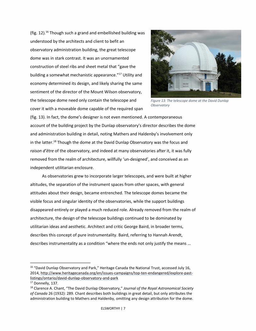
(fig. 12).16 Though such a grand and embellished building was
understood by the architects and client to befit an
observatory administration building, the great telescope
dome was in stark contrast. It was an unornamented
construction of steel ribs and sheet metal that “gave the
building a somewhat mechanistic appearance.”17 Utility and
economy determined its design, and likely sharing the same
sentiment of the director of the Mount Wilson observatory,
the telescope dome need only contain the telescope and
cover it with a moveable dome capable of the required span
(fig. 13). In fact, the dome’s designer is not even mentioned. A contemporaneous
account of the building project by the Dunlap observatory’s director describes the dome
and administration building in detail, noting Mathers and Haldenby’s involvement only
in the latter.18 Though the dome at the David Dunlap Observatory was the focus and
raison d’être of the observatory, and indeed at many observatories after it, it was fully
removed from the realm of architecture, willfully ‘un-designed’, and conceived as an
independent utilitarian enclosure.
As observatories grew to incorporate larger telescopes, and were built at higher
altitudes, the separation of the instrument spaces from other spaces, with general
attitudes about their design, became entrenched. The telescope domes became the
visible focus and singular identity of the observatories, while the support buildings
disappeared entirely or played a much reduced role. Already removed from the realm of
architecture, the design of the telescope buildings continued to be dominated by
utilitarian ideas and aesthetic. Architect and critic George Baird, in broader terms,
describes this concept of pure instrumentality. Baird, referring to Hannah Arendt,
describes instrumentality as a condition “where the ends not only justify the means …
16 “David Dunlap Observatory and Park,” Heritage Canada the National Trust, accessed July 16, 2014, http://www.heritagecanada.org/en/issues-campaigns/top-ten-endangered/explore-past-listings/ontario/david-dunlap-observatory-and-park 17 Donnelly, 137. 18 Clarence A. Chant, “The David Dunlap Observatory,” Journal of the Royal Astronomical Society of Canada 26 (1932): 289. Chant describes both buildings in great detail, but only attributes the administration building to Mathers and Haldenby, omitting any design attribution for the dome.
Figure 13: The telescope dome at the David Dunlap Observatory

ELSWORTHY | 8
but produce and organise them,”19 where architecture is characterized above all by its
productivity and use value. Indeed, a narrow interpretation of rigorous functionalism
and economy were, and still are, primary concerns in observatory design, and with time
began to dictate the form and design of the buildings. The Kitt Peak National
Observatory, California (1962); Mauna Kea Observatory, Hawaii (1967); MMT
Observatory, Mount Hopkins Arizona (1987); and Paranal Observatory, Chile (1998)
(figs. 14-17), clearly illustrate this functionalist and instrumental approach.
In the midst of this general movement from the early observatory as a
monumental and complete work of architecture, to the contemporary observatory as a
fragmented and instrumentalized cluster of telescope sheds, there are some notable
exceptions. Indeed even within the examples I have listed so far there are outliers. For
instance, the McMath-Pierce solar telescope at the Kitt Peak Observatory, designed by
19 George Baird, The Space of Appearance (Cambridge, MA: MIT Press, 1995), 133.
Figure 15: Mauna Kea Observatory, Hawaii. Figure 14: Kitt Peak Observatory, California.
Figure 16: The MMT (multi mirror telescope) at Mt Hopkins Observatory, Arizona.
Figure 17: Paranal Observatory, Chile.

ELSWORTHY | 9
Skidmore Owings & Merrill (fig. 18), gracefully incorporates
functional requirements, challenging mechanics and cooling
into an elegant and monumental form that evokes two
balancing obelisks.
Erich Mendelsohn’s Einstein Tower is another poignant
exception. Designed between 1917 and 1920, and built
between 1920 and 1922, the tower (fig. 19) is described by
architectural historian Kathleen James as “a pivotal point
between the prewar fascination many German architects had
with monumental architecture and the postwar neue
Sachlichkeit substitution of technology for pomp.”20 Designed
to house instruments to test Einstein’s theory of relativity by
observing the sun’s light spectra, the “Tower provides the first
example of what became Mendelsohn's characteristic
manipulation of dynamic form within functional bounds, as he
attempted both to represent and serve Einstein's
controversial new scientific theory.”21 Working closely with
his friend, and client for the tower, astrophysicist Erwin Finlay
Freundlich, Mendelsohn responded carefully to the technical requirements of the solar
telescope and other programme spaces. Mendelsohn was also profoundly influenced by
Einstein’s theory of relativity, and the equivalence of matter and energy dictated by the
theory shaped his idea of the relationship between mass, motion, and light. He
conceived of matter as fluid and animate, and of the tower as an organism – a hybrid
form of technology and a living body.22 The sculpted curves of the overall massing,
window openings, and even roof scuppers, evoke the dynamism of a body moving
through space (fig. 20), articulating his understanding of the technology and character of
its materials – the steel skeleton supporting a plastic reinforced concrete flesh23 – and at
20 Kathleen James, “Expressionism, Relativity, and the Einstein Tower.” Journal of the Society of Architectural Historians 23, no. 4 (Dec. 1994): 405. 21 Ibid, 392. 22 Ibid, 407. 23 James, 405. James notes that Mendelsohn’s vision of plastic sculptural reinforced concrete may well have been naïve, and owing partly to the challenge of forming the curves, and to cost saving the tower is mostly constructed of brick and plaster stucco.
Figure 14: The McMath-Pierce solar telescope at Kitt Peak, designed by Skidmore Owings & Merrill.
Figure 15: Erich Mendelsohn's Einstein Tower, Potsdam, Germany.

ELSWORTHY | 10
the same time, capturing the cultural spirit of its time, evoking
the movement of Kandinsky’s expressionist painting and
dynamism of Boccioni’s sculpture.24 The Einstein Tower is
often cited as an example of expressionist architecture, and
was criticized by proponents of the neue Sachlichkeit as
irrational, eccentric, individual, and monumental. However,
by looking more closely at Mendelsohn’s ideas and design
process, the tower can also be seen as a rational attempt to
genuinely express the theory of relativity in built form.
My design for a nature centre is a nuanced response to
the legacy of observatory design and to Mendelsohn’s particular design process. Rather
than rejecting the narrowly functional and instrumental condition of observatory design,
I propose an expanded approach to instrumentality, drawing in multiple and layered
considerations of building technology, thermal movement and mechanical systems,
structural forces, programme and function, vernacular building, and environmental
stewardship, into the design process. This extends Mendelsohn’s approach, in the sense
that the design incorporates the technical and programmatic requirements, material
characteristics, and expresses its function in architectural terms, but rather than seeking
to represent its generative ideas formally, the nature centre explores the limits of this
multifold instrumentality, and embodies them in a finely-tuned and integrated
architecture.
In its relationship to the neutrino observatory, the nature centre and neutrino
detector caverns are also analogous to the physically separated elements of an
astronomical observatory. Where the neutrino observatory is a collection of spaces that
house detectors and experiments, the nature centre contains a wide range of ancillary
and supplementary programme that relate to its role as a support building, and its
alpine context. However, my design for the nature centre rejects the aesthetic
dichotomy between science spaces and public or support spaces, between instrumental
and monumental architecture, instead pursuing a hybrid approach that through
24 Ibid, 394-407.
Figure 16: Detail of the Einstein Tower’s window openings and scupper.

ELSWORTHY | 11
multiplied, interwoven instrumentality expresses its cultural significance in the close
attention paid to its physical, cultural, and environmental context.
Conceived as the outward expression of an underground observatory buried deep
beneath the France-Italy border, the nature centre sits at the mouth of the observatory
access tunnel and cantilevers over the excavation spoil heap, looking over the town of
city below. The nature centres acts as a beacon and entrance point for the hidden
observatory, pointing to its presence and indicating the scale of the hollow underground
spaces by the enormous quantity of stock-piled excavation spoil. The excavation
process, and the synthetic landscape that results, are central to the form and focus of
the nature centre, which examines strategies for the ecological regeneration of the spoil
heap. The form and structural system of the nature centre directly engage the spoil
mound as an anchor and counterweight for the cable stays that support the
cantilevered building. The nature centre is coupled thermo-dynamically to the
observatory, and forms the end of a thermal loop. It removes the geothermal heat that
accumulates within the mountain, using it to generate electricity and warm thermal
baths that are buried within the spoil mound.
Reaching out in order to look back on the spoil, the nature centre manifests a
speed and trajectory that suggest an energetic source deep within the rock. Like the
Main Ring Lake at Fermilab outside of Batavia, Illinois, the form of the nature centre and
the spoil mound itself trace, and refer to, subterranean space. However, unlike the Main
Ring Lake, the references here are not direct transpositions of form, but isometric and
scalar translations that reveal only partial information. The spoil mound volume
indicates the aggregated scale of the underground caverns that make up the neutrino
observatory, but gives no indication of their configuration. But even with this intuitive
and physical reference to the magnitude of hollow underground space, precise
estimation is challenged, since the only the surface dimensions are knowable and the
depth of the spoil mound is unclear. One is left with a tangible feeling of something that
one cannot objectively know.
The nature centre is coupled thermodynamically with the neutrino observatory,
acting both as a radiator and absorber of the geothermal energy accumulated in the
observatory. The ambient rock temperature in the heart of the Col du Fréjus is nearly

ELSWORTHY | 12
38°C. This unremitting heat surrounds the
observatory spaces, necessitating constant
cooling of the labs. The neutrino detectors
themselves operate optimally at 12°C, setting
up an even steeper temperature gradient. As
heat is constantly pulled out of the
observatory environment, it is transferred to
a water loop that is piped to the nature
centre where the geothermal ‘waste’ heat is
used for heat and power (fig. 21). A thermal transfer station within the nature centre
concentrates the heat and generates electricity with a micro-turbine. The hot water
loop is used to heat the pools in the thermal bath, and the building’s radiant heating
system. Finally, the upper spoil mound functions as a natural draft cooling tower, and
evaporatively cools water as it percolates through the loose rock before returning it to
the observatory.25
The excavation of the observatory chambers and access tunnel causes a radical
re-organization of the geological strata, disrupting the churned forms of metamorphic
rock, and replacing it with a new indistinct fluidity. The sedimentary precursors of the
calcareous schist that make up the Col du Fréjus were laid down layer by layer in
horizontal strata at the bottom of an ancient ocean. Under immense pressure and
temperature, these sediment were gradually transformed into foliated schists, which
were again deformed as the tectonic plates collided in slow-motion, crumpling, twisting,
and folding the layered rock. The resulting rock mass is at once ordered and convoluted,
seemingly static in a human frame of reference, but behaving like an viscous fluid at the
scale of geological time. The order and placement of the various rock types, veins of
mineral inclusions, and rock strata are broken by the boring machine in the excavation
process, and are transplanted from the centre of the mountain to its surface and
deposited in a near homogenous arrangement. As the tunnel boring machine inches
through the rock, each successive layer of the vertical rock face it encounters is
25 More recent development of my nature centre design moves the evaporative cooling from the spoil to a mesh sheath that wraps the cantilevered building exoskeletal matrix, enveloping the centre in a misty veil. Strategically placed openings in the mesh direct updrafts which punctuate the fog and allow views out to the landscape.
Figure 17: Diagram of thermal exchange loop linking the nature centre and neutrino observatory

ELSWORTHY | 13
pulverized and transported to surface where it is dumped down the face of the growing
spoil mound. Since the excavation and disposal process is incremental, what was once
finely layered solid becomes a dispersed rock ‘foam’ that is deposited in diagonal layers
that homogenize and blur all detail, maintaining only macroscopic differences. The
process of removal transfers the borders between geologically distinct nappes to the
spoil heap, retaining basic information about broad changes in rock type, but muddling
the boundary between them, and allowing the distinct types to overlap and bleed into
each other.
The nature centre focuses on this synthetic landscape
of excavation spoil, using it to examine the regeneration of
sensitive ecosystems after the devastation of rockslides, the
dispersal of mine tailings, or other scarred landscapes. From
its extended position, the nature centre offers an opportunity
to observe the process of unassisted re-naturalization, and
monitor active strategies for regeneration including re-
forestation, directed plantings, and low-intensity agriculture
(fig. 22). These diverse strategies for regrowth can be seen by
visitors and nature centre staff from the long observation
deck promontory on top of the nature centre building, and
can also be explored along walking trails that connect a number of large and small
terraced areas and lookouts. This focus on the establishment of plant and animal life of
the spoil mound anticipates a range of naturally occurring and manmade conditions,
including the frequent rockslides that occur throughout the Alps, the corresponding
need to stabilize loose material, the construction of the Lyon-Turin base tunnel and the
resulting massive volume of spoil it will create, and the more general questions of
mending the scarred landscapes of ore tailings, open pit mines, and the residues of tar
sands extraction.
In addition to being the nature centre’s focus of study, the spoil mound is also its
physical foundation, providing the weight necessary to enable the nature centre’s
reaching lightness. A splayed array of cable support the cantilevered nature centre,
connecting to nodes on the centre’s exoskeletal structural matrix. The regular cable
array distributes the nodes in such a way as to create an evolving irregular three
Figure 18: Plan diagram showing placement of re-growth strategies.

ELSWORTHY | 14
dimensional truss matrix (fig. 23), the form of which evokes a
sense of movement akin to the photographs of Etienne Jules
Marey (fig. 24), and recalls Hans Grubenmann’s remarkable
layered alpine wood bridge designs (fig. 25).26 As the cables
extend back towards the spoil mound, they are gathered into
two thick bundles at the moment they pass through the
surface of the spoil mound. At this point of concentration, the
cable bundles run over steel saddles sitting atop two massive
concrete struts. The cables then disperse into the spoil heap,
subdividing into smaller and smaller bundles in order to
establish themselves in a three dimensional network of low-
strength friction anchors. This strategy distributes the forces
over a diffuse area, activating the aggregated weight and
internal friction of a sizable portion of the loose spoil to
anchor the cantilevered building. The floor diaphragms gather
the compression forces needed to balance the pull of the
cable stays. A series of ribs and gradual thickening of the slabs
direct the forces into four asymmetric tubular struts. The
hollow centres of the struts carry building services of serves
as the connecting walkways between the underground and
above ground spaces.
Upon arrival to the nature centre, visitor pass through a
series of large buried voids in the spoil mass, walking beneath
the thermal transfer station and thermal baths. Climbing a staircase within one of the
hollow structural struts, visitors pass through surface of the spoil, and arrive at an open
reception area and information desk. Two large exhibition spaces house permanent
displays, accommodate visiting exhibitions, and serve as large multi-purpose spaces.
Two medium-sized tiered multimedia classrooms can be used individually for workshops
and seminars related to the nature centre’s or observatory’s activities, or combined into
26 Angelo Maggi, Nicola Navone, eds., John Soane and the Wooden Bridges of Switzerland: Architecture and the Culture of Technology from Palladio to the Grubenmanns (London: Sir John Soane's Museum; Mendrisio, Switz.: Archivio del Moderno, Accademia di architettura, Università della Svizzera Italiana: 2003).
Figure 21: Étienne-Jules Marey, Walking Man, chronophotography, 1884.
Figure 20: Elevation of the nature centre's external structural matrix.
Figure 19: Grubenmann's design for the Schaffhausen Bridge.

ELSWORTHY | 15
one large hall for presentation and conference addresses. A café and restaurant are
located at the tip of the nature centre has views out over the spoil mound, the alpine
valley, and city below. In addition to these extroverted uses, nature centre building also
includes a small hotel and thermal bath. Tourists and visiting scholars are
accommodated in seven rooms that look out to the surroundings. A series of hot, cold,
and tepid pools are buried within the spoil mass, reinterpreting the heritage of
colonizing natural hot springs, and creating an abstracted equivalent that is displaced
from its geothermal source in the heart of the Alps, and transposed from a usual home
on a mountain side to voids within the newly foamed rock.
In a broader sense, the nature centre’s program also compliments that of the
neutrino observatory, operating at physical and timescales between the extremes
explored in neutrino physics. Where the neutrino detectors study phenomena at
incredibly small sub-atomic scales, and explore their relationship to incredibly large
scale questions,27 the nature centre operates in the intervening scales, centering on the
scale of a human and extending down to the realm of plant biology and up to the scale
of geology. By focusing on the particular and subtle characteristics of the many
disciplines, systems, energy flows, and technology that overlap in the nature centre, an
expansive and multi-layered instrumental design approach emerges. This manifold
instrumentality offers an alternative to the narrow functionalism and segregation that
has generally come to pervade the design of spaces for science, without rejecting it
outright in favour of a return to monumentality. Instead, by engaging in a detailed way
with multiple frames of reference, the result is an evocative and highly specific
architecture.
27 Neutrinos range in size from approximately 1x10-26m to 1x10-26m. Neutrinos may provide a way of understanding the matter and anti-matter asymmetry that was produced during the formation of elementary particles during the processes of baryogenesis and leptogenesis that occurred in the early stages of the universe in the big bang. Neutrinos may also offer a means to see beyond the cosmic microwave background radiation that defines the edge of the observable universe.
ELSWORTHY | 16
Bibliography
Baird, George. The Space of Appearance. Cambridge, MA: MIT Press, 1995.
Chant, Clarence A. “The David Dunlap Observatory.” Journal of the Royal Astronomical Society of Canada 26 (Sept. 1932): 289-290. Donnelly, Marian Card. A Short History of Observatories. Eugene, Oregon: University of Oregon Books, 1973. Dolan, Graham. “Flamsteed House and the Early Observatory.” The Royal Observatory Greenwich. Accessed July 1, 2014. http://www.royalobservatorygreenwich.org/articles.php?article=916. Heck, André, ed. A Multinational History of the Strasbourg Observatory. Dordrecht: Springer, 2005. Accessed, July 10, 2014. http://link.springer.com.proxy.lib.uwaterloo.ca/book/10.1007%2F1-4020-3644-2 Edward S. Holden. “Notes on the Early History of Lick Observatory.” Publications of the Astronomical Society of the Pacific 4, no. 24 (June 11, 1982): 139. Quoted in Donnelly. James, Kathleen. “Expressionism, Relativity, and the Einstein Tower.” Journal of the Society of Architectural Historians 23, no. 4 (Dec. 1994): 392-413. Accessed July, 4 2014. http://www.jstor.org/stable/990909. Maggi, Angelo, Nicola Navone, eds. John Soane and the Wooden Bridges of Switzerland: Architecture and the Culture of Technology from Palladio to the Grubenmanns. London: Sir John Soane's Museum; Mendrisio, Switz.: Archivio del Moderno, Accademia di Architettura, Università della Svizzera Italiana: 2003. Le Guet Tully, Françoise. “La Patrimoine de l’OCA: Disposition des bâtiments sur le site.” Observatoire de la Côte d'Azur. Accessed June 17, 2014. http://patrimoine.oca.eu/spip.php?article50. Carnegie Observatories. “The Carnegie Observatories: History.” Accessed July 18, 2014. http://obs.carnegiescience.edu/about/history. Heritage Canada the National Trust. “David Dunlap Observatory and Park.” Accessed July 16, 2014. http://www.heritagecanada.org/en/issues-campaigns/top-ten-endangered/explore-past-listings/ontario/david-dunlap-observatory-and-park. TychoBrahe.com. “Uraniborg - Observatory, Laboratory and Castle.” Accessed July 15, 2014. http://www.tychobrahe.com/UK/uraniborg.html.

ELSWORTHY | 17
List of Figures Figure 1: Tycho Brahe's 16th century naked-eye observatory Uraniborg. (Etching coutesy
of The Tycho Brahe-museum, accessed July 10, 2014, http://www.tychobrahe.com/press_bilder.html)
Figure 2: Maharaja Jai Singh II’s 18th century Jantar Mantar, Jaipur, India. (Photo by Saranya Ghosh, accessed July, 12 2014, http://commons.wikimedia.org/wiki/Category:Jantar_Mantar_%28Jaipur%29)
Figure 3: Maharaja Jai Singh II’s 18th century Jantar Mantar, Jaipur, India. (Photo by Viraat Kothare, accessed July, 12 2014, http://commons.wikimedia.org/wiki/Category:Jantar_Mantar_%28Jaipur%29)
Figure 4: The large mural quadrant and small wall slit used to record star positions at Uraniborg. (Engraving from the book: Tycho Brahe, Astronomiae instauratae mechanica, Wandsbeck, accessed July 4, 2014, http://commons.wikimedia.org/wiki/File:Tycho-Brahe-Mural-Quadrant.jpg)
Figure 5: North elevation of the Royal Greenwich Observatory. (Etching from Flamsteed, Historiae coelestis, photo courtesy Royal Greenwich Observatory; from Marian Card Donnelly, A Short History of Observatories (Eugene, Oregon: University of Oregon Books, 1973), 24.)
Figure 6: Floor plans of the Royal Greenwich Observatory. (Image from The Royal Observatory, Greenwich. RCHM, London, V, East London, 1930; from Marten Kuilman, "4.2.5. Observatories, libraries and the internet," Quadralectic Architecture, accessed July 4, 2014, http://quadralectics.wordpress.com/4-representation/4-2-function/4-2-5-observatories-libraries-and-the-internet/)
Figure 7: Comparison of the floor plans of the Gottingen (above) and Pulkovo (below) observatories. (Drawings by Marion Card Donnelly, from Marian Card Donnelly, A Short History of Observatories (Eugene, Oregon: University of Oregon Books, 1973), 66 & 73.)
Figure 8: Floor plan of the Strasbourg Observatory showing the three distinct building and covered walkway. (Drawing by Marion Card Donnelly, from Marian Card Donnelly, A Short History of Observatories (Eugene, Oregon: University of Oregon Books, 1973), 110.)
Figure 9: Photo of the Strasbourg Observatory. The great dome is on the left, and the residence is on the right. (Photo by C. Menninger, from La Médiathèque de l'Architecture et le Patrimoine, accessed July 10, 2014, http://www.culture.gouv.fr/public/mistral/memoire_fr?ACTION=CHERCHER&FIELD_5=LBASE&VALUE_5=IA67007884)
Figure 10: The Nice Observatory distributed on the slopes of Mont Gros. (Photo by Marc Heller, from "Histoir et patrimoine," Observatoire de la Côte d'Azur, accessed July 10, 2014, http://patrimoine.oca.eu/)
Figure 11: Photo of the telescope building at the Nice Observatory showing Garnier and Eiffel's floating dome under construction. Also note the winged Egyptian god above the entrance. (photographer unknown, from "Large Equatorial Refractor (1887) and Eiffel's dome," accessed July 10, 2014, https://www-n.oca.eu/histoire-nice_en/large_equatorial_refractor.html)
Figure 12: Mathers and Haldenby's adminsitration building at the David Dunlap Observatory. (Photo by James Victor Salmon, from Toronto Public Library, accessed July 10, 2014,

ELSWORTHY | 18
http://www.torontopubliclibrary.ca/detail.jsp?Entt=RDMDC-PICTURES-R-3211&R=DC-PICTURES-R-3211)
Figure 13: The telescope dome at the David Dunlap Observatory. (Photo by Canuck, from "Photo of the David Dunlap Observatory in Richmond Hill Ontario Canada," accessed July 10, 2014, http://www.panoramio.com/photo/4625405)
Figure 14: Kitt Peak Observatory, California. (image credit: NOAO/AURA/NSF, from "Kitt Peak Observatory," National Optical Astronomical Observaotry: KPNO, accessed July 10, 2014, http://www.noao.edu/image_gallery/html/im0411.html
Figure 15: Mauna Kea Observatory, Hawaii. (Photo by Donnie McGowan, from " The Hawaiian Snow Goddess Poliahu and the Summit of Mauna Kea,"
Lovingthebigisland’s Weblog, accessed July 10, 2014, http://lovingthebigisland.wordpress.com/2009/02/05/the-hawaiian-snow-goddess-poliahu-and-the-summit-of-mauna-kea/)
Figure 16: The MMT (multi mirror telescope) at Mt Hopkins Observatory, Arizona. (Photo by J.T. Williams, from "e-Torch," Smithsonian, accessed July 10, 2014, http://www.e-torch.org/2013/09/september-29-1970-2/)
Figure 17: Paranal Observatory, Chile. (image credit: ESO, from "VLT at Paranal," Eastern Southern Observatory, accessed July 10, 2014, http://www.eso.org/public/images/eso9951b/)
Figure 18: The McMath-Pierce solar telescope at Kitt Peak, designed by Skidmore Owings & Merrill. (Photo by John Owens, from "AD Classics: McMath-Pierce Solar Telescope, Kitt Peak National Observatory / SOM," ArchDaily, accessed July 10, 2014, http://www.archdaily.com/121364/ad-classics-mcmath-pierce-solar-telescope-kitt-peak-national-observatory-som/)
Figure 19: Erich Mendelsohn's Einstein Tower, Potsdam, Germany. (Photo by R. Arlt, AIP, from "Einstein Tower," Liebniz-Institut für Astrophysik Potsdam, accessed July 10, 2014, http://www.aip.de/en/press/images/premises/telegrafenberg)
Figure 20: Detail of the Einstein Tower’s window openings and scupper. (Photo by George Marshall, from Flickr, accessed July 10, 2014, https://www.flickr.com/photos/47665894@N04/4367059857)
Figure 21: Diagram of thermal exchange loop linking the nature centre and neutrino observatory. (Diagram by authour)
Figure 22: Plan diagram showing placement of re-growth strategies. (Diagram by authour)
Figure 24: Grubenmann's design for the Schaffhausen Bridge. (Etching from Angelo Maggi, Nicola Navone, eds., John Soane and the Wooden Bridges of Switzerland: Architecture and the Culture of Technology from Palladio to the Grubenmanns (London: Sir John Soane's Museum; Mendrisio, Switz.: Archivio del Moderno, Accademia di architettura, Università della Svizzera Italiana, 2003), 41.)
Figure 23: Elevation of the nature centre's external structural matrix. (Drawing by authour)
Figure 25: Étienne-Jules Marey, Walking Man, chronophotography, 1884. (Photo by Étienne-Jules Marey, from "The Art of Deceleration, Wolfsburg," Futur-ism, accessed July, 20, 2014, http://www.futur-ism.it/esposizioni/Esp2011/ESP20111211_W.htm)
![LIMIT SWITCHES Series - HH Hermetically Sealed Switchesflamecorp.com/.../Safran-Electrical-Power,HH.pdf · 2020-03-25 · hh-695 series 1.ai 1.031 [26,2] dia. max. max. dia. (ref)](https://static.fdocuments.in/doc/165x107/5f53004675eb3063806807b8/limit-switches-series-hh-hermetically-sealed-hhpdf-2020-03-25-hh-695-series.jpg)