DHANALAKSHMI SRINIVASAN ENGINEERING COLLEGE … SOLID STATE DRIVES.pdfiii) They are available in...
54
DHANALAKSHMI SRINIVASAN ENGINEERING COLLEGE-PERAMBALUR-621212 DEPARTMENT OF EEE EE6601/SOLID STATE DRIVES III YEAR/VI SEM UNIT-1-DRIVE CHRACTERSTICS PART-A I – Unit 1. What is meant by electrical drives? MAY2015, MAY2014, Systems employed for motion control are called drives. And many employ any of the prime movers such as diesel or petrol engines, as or steam turbines, hydraulic motors and electric motors for supplying mechanical energy for motion control. Drives employing electrical motors are known as electrical drives. 2. What are the three modes of operation for electric drive? NOV2017, MAY2013, NOV2010 Steady state, Acceleration including starting and Deceleration including stopping. 3. What is dynamic torque? NOV2015, MAY2015, MAY2014, MAY2011, MAY2010 Torque component Jdw m /dt is called the dynamic torque because it is present only during the transient operations. 4. What are the advantages of electrical drives? NOV2012, NOV2011 i) They have flexible control characteristics. The steady state and dynamic characteristics of electrical can be shaped to satisfy load requirements. ii) Drives can be provided with automatic fault detection system. iii) They are available in wide range of torque, speed and power. iv) It can operate in all four quadrants of speed-speed plane. v) Control gear required for speed control, starting and braking is usually simple and easy to operate. 5. List out the various components used in electrical drive systems. MAY2015, MAY2014, Electrical motors, Power modulator, Sources, Control Unit and sensing unit. 6. What are the applications of electrical drives? NOV2016, Paper mills, Electric traction, Cement mills and Steel mills. 7. Write the best choice of electric motor for the following application. NOV2016, may2010 1. Pump Load - Single or three phase cage induction motors 2. Elevator – DC series motor, slip ring induction motor. 8. Write the fundamental torque equation for dynamic electric drives.NOV2017 T=T L + Jdw m /dt T= Developed motor torque, N-m. T L = Load torque referred to motor shaft, N-m. J=Moment of inertia, kg-m 2 . W m = Angular velocity of motor shaft, rad /sec. 09. What are the components of load torque? MAY2012, MAY2011 Friction torque, Windage torque and torque required to the useful mechanical work. 10.What are the typical elements of an electric drive?NOV2017 Sources ,Power modulator,Dc motor,Control circuit
Transcript of DHANALAKSHMI SRINIVASAN ENGINEERING COLLEGE … SOLID STATE DRIVES.pdfiii) They are available in...

DHANALAKSHMI SRINIVASAN ENGINEERING COLLEGE-PERAMBALUR-621212
DEPARTMENT OF EEE
EE6601/SOLID STATE DRIVESIII YEAR/VI SEM
UNIT-1-DRIVE CHRACTERSTICSPART-A
I – Unit
1. What is meant by electrical drives? MAY2015, MAY2014,
Systems employed for motion control are called drives. And many employ any of the prime
movers such as diesel or petrol engines, as or steam turbines, hydraulic motors and electric motors for
supplying mechanical energy for motion control. Drives employing electrical motors are known as
electrical drives.
2. What are the three modes of operation for electric drive? NOV2017, MAY2013, NOV2010
Steady state, Acceleration including starting and Deceleration including stopping.
3. What is dynamic torque? NOV2015, MAY2015, MAY2014, MAY2011, MAY2010
Torque component Jdwm/dt is called the dynamic torque because it is present only during the
transient operations.
4. What are the advantages of electrical drives? NOV2012, NOV2011
i) They have flexible control characteristics. The steady state and dynamic characteristics of electrical can
be shaped to satisfy load requirements.
ii) Drives can be provided with automatic fault detection system.
iii) They are available in wide range of torque, speed and power.
iv) It can operate in all four quadrants of speed-speed plane.
v) Control gear required for speed control, starting and braking is usually simple and easy to operate.
5. List out the various components used in electrical drive systems. MAY2015, MAY2014,
Electrical motors, Power modulator, Sources, Control Unit and sensing unit.
6. What are the applications of electrical drives? NOV2016,
Paper mills, Electric traction, Cement mills and Steel mills.
7. Write the best choice of electric motor for the following application. NOV2016, may20101. Pump Load - Single or three phase cage induction motors 2. Elevator – DC series motor, slip ring induction motor.
8. Write the fundamental torque equation for dynamic electric drives.NOV2017
T=TL + Jdwm/dt
T= Developed motor torque, N-m.
TL = Load torque referred to motor shaft, N-m.
J=Moment of inertia, kg-m2.
Wm= Angular velocity of motor shaft, rad /sec.
09. What are the components of load torque? MAY2012, MAY2011
Friction torque, Windage torque and torque required to the useful mechanical work.
10.What are the typical elements of an electric drive?NOV2017
Sources ,Power modulator,Dc motor,Control circuit

PART-B
1. State the essential parts of electrical drive. What are the functions of power modulator?(Nov12,Nov11)
o Modern power electronics and drives are used in electrical as well as mechanical
industry. o The power converter or power modulator circuits are used with electrical motor drives,
providing either DC or AC outputs, or working from either a DC (battery) supply or fromthe conventional AC supply.
2. Explain in detail about multi quadrant operations. (Nov17, Nov15, may15,May14,Nov14,may13,Nov13,may12)Four quadrant operation of a drive
I quadrant II quadrant III quadrant IV quadrant Operation of the
Hoist
The hoisting up
of the loaded cage
The hoisting up
of the unloaded
cage
The downward
motion of the
unloaded cage
The downward
motion of the
loaded cage Te +VE -VE -VE +VE
TL -VE +VE +VE -VE

WM +VE +VE -VE -VE
Power +VE -VE +VE -VE Operation of the
Drive
forward motoring Forward Braking Reverse motoring Reverse Braking
3. What are the different modes of operation of electric drives and explain it(may15,may13)
Modes of Operation:
An electrical drive operates in threemodes:
Steady state
Acceleration including Starting
Deceleration including Stopping
According to the above expression the steady state operation takes place when motor
torque equals the load torque. The steady state operation for a given speed is realized by adjustment
of steady state motor speed torque curve such that the motor and load torques are equal at this
speed.
Change in speed is achieved by varying the steady state motor speed torque curve so that
motor torque equals the load torque at the new desired speed. In the figure shown below when the
motor parameters are adjusted to provide speed torque curve 1, drive runs at the desired speed wm1.
Speed is changed to wm2 when the motor parameters are adjusted to provide speed torque curve 2.
When load torque opposes motion, the motor works as a motor operating in quadrant I or III
depending on the direction of rotation.
When the load is active it can reverse its sign and act to assist the motion. Steady state
Operation for such a case can be obtained by adding a mechanical brake which will produce a
torque in a direction to oppose the motion. The steady state operation is obtained at a speed for
which braking torque equal the load torque. Drive operates in quadrant II or IV depending upon the
rotation.

Acceleration and Deceleration modes are transient modes. Drive operates in acceleration
mode. Whenever an increase in its speed is required. For this motor speed torque curve must be
changed so that motor torque exceeds the load torque. Time taken for a given change in speed
depends on inertia of motor load system and the amount by which motor torque exceeds the load
torque.
Increase in motor torque is accompanied by an increase in motor current. Care must be
taken to restrict the motor current within a value which is safe for both motor and power modulator.
In applications involving acceleration periods of long duration, current must not be allowed to
exceed the rated value. When acceleration periods are of short duration a current higher than the
rated value is allowed during acceleration. In closed loop drives requiring fast response, motor
current may be intentionally forced to the maximum value in order to achieve high acceleration.
Figure shown below shows the transition from operating point A at speed wm1 to operating
point B at a higher speed wm2, when the motor torque is held constant during acceleration.
The path consists of AD1E1B. In the figure below, 1 to 5 are motor speed torque curves. Starting is
a special case of acceleration where a speed change from 0 to a desired speed takes place. All
points mentioned in relation to acceleration are applicable to starting. The maximum current
allowed should not only be safe for motor and power modulator but drop in source voltage
caused due to it should also be in acceptable limits. In some applications
the motor should accelerate smoothly, without any jerk. This is achieved when the starting torque
can be increased step lessly from its zero value. Such a start is known as soft start.

Motor operation in deceleration mode is required when a decrease in its speed is required.
According to the equation deceleration occurs when load torque exceeds the motor torque. In those
applications where load torque is always present with substantial magnitude, enough deceleration
can be achieved by simply reducing the motor torque to zero. In those applications where load
torque may not always have substantial amount or where simply reducing the motor torque to
zero does not provide enough deceleration, mechanical brakes may be used to produce the required
magnitude of deceleration. Alternatively, electric braking may be employed. Now both motor and
the load torque oppose the motion, thus producing larger deceleration. During electric braking motor
current tends to exceed the safe limit. Appropriate changes are made to ensure that the current is
restricted within the safe limit.
Figure shown above shows paths followed during transition from point A at speed wm1
to a point C at a lower speed wm3 .When deceleration is carried out using electric braking at a
constant braking torque, the operating point moves along the path AD3E3C. When sufficient load
torque is present or when mechanical braking is used the operation takes place along the
Path AD2E2C. Stopping is a special case of deceleration where the speed of a running motor is
changed to zero.
4. Derive the condition for steady state stability of equilibrium
point(may16,may14,nov14,may13,nov13,may11,may10)
Equilibrium speed of a motor load system is obtained when the motor torque, Te equals the load
torque T l. Stable state of equilibrium point
The equilibrium point is termed as stable, if the operating point is restored after a smalldeparture from it due to disturbance in the motor or load.
Unstable state of equilibrium point The equilibrium point is termed as stable, if the operating point will not be restored after a
small departure from it due to disturbance in the motor or load.

Mathematical condition for the stability of the equilibrium point
5. Explain the typical load torque characteristics of electrical drives.(may15,nov13,may13,nov12,may11)
Types and Characteristics of Load Torque Classification of load torques:1. Active Load torques2. Passive Load torquesActive Load Torques:Load torques which has the potential to drive the motor under equilibrium conditions are called active load torques.Load torques usually retains sign when the drive rotation is changed.Active Load Torques Passive Torque:Load torques which always oppose the motion and change their sign on the reversal of motion arecalled passive load torques.Torque due to friction cutting – Passive torque.Components of load torques:1. Friction Torque (TF)The friction torque (TF) is the equivalent value of various friction torques referred to the motor shaft.2. Windage Torque (Tw)When a motor runs, the wind generates a torque opposing the motion. This is known as the winding torque.3. Torque required to do useful mechanical work (Tm)Nature of the torque depends of type of load.It may be constant and independent of speed, some function of speed, may be time invariant or time variant.The nature of the torque may change with the change in the loads mode of operation.Characteristics of different types of load:In electric drives the driving equipment is an electric motor.Selection of particular type of motor driving a m/c is the matching of speed-torque charal of the driven unit and that of the motor. Different types of loads exhibit different speed torque charal.· Most of the industrial loads can be classified into the following 4 general categories:1. Constant torque type load.2. Torque proportional to speed (generator type load)3. Torque proportional to square of the speed (fan type load)4. Torque inversely proportional to speed (const power type load)1. Constant Torque Characteristic :

The speed – torque characteristic of this type of load is given by T=K.Working motor have each mechanical nature of work like shaping , cutting, grinding or sharing, require constant torque irrespective of speed. Similarly cranes during the hoisting.Similarly cranes during the hoisting and conveyors handling constant weight of material / unit, time also exhibit this type of characteristics.Torque proportional to speed:
Separately execited dc generators connected to a constant resistance load, eddy current brakes andcalendaring m/cs have a speed torque characteristics m/cs have a speed – torque characteristics given by T= Kw.Torque propositional to square of the speed:
Load Torque Square of speedExample : Fans , Rotary pumps , compressors , ship propellers. The speed – torque characteristicsof this type of load is given by Torque inversely propositional to speed:

· In such types of loads , torque is inversely proportional to speed or load power remains constant. · Eq: Lathes, boring m/cs, milling m/cs , steel mill colier and electric traction load. · This type of characteristics is given by · Most of the load require extra effort at the time of starting to overcome static friction. In power
application it is known as brake away torque and load control engineers call it “stiction” . The speed torque characteristics of the load are modified near to zero speed.
6. What are the main factors which decide the choice of electrical drives? Nov17, Nature of electric supply
Whether AC or DC supply is to be used for supply
· Nature of the drive
Whether the particular motor is going to drive individual machine or a group
of machines Capital and running cost
· Maintenance requirement
· Space ad weight restrictions
· Environment and location
· Nature of load
Whether the load requires light or heavy starting torque Whether load torque increases with speed remain constant Whether the load has heavy inertia which may require longer straight time
· Electrical characteristics of motor
Starting characteristics, Running characteristics, speed control and Braking characteristics
Size, rating and duty cycle of motors Whether the motor is going to the operator for a short time or whether it has to run continuously
intermittently or on a variable load cycle
Mechanical considerations Type of enclosures, type of bearings, transmission of drive and Noise level. Due to practical difficulties, it may not possible to satisfy all the above considerations. In such circumstances, it is the experience and knowledge background which plays a vital role in
the selection of the suitable drive.
The following points must be given utmost important for the selection of motor.

The factors are:
Nature of the mechanical load driven Matching of the speed torque characteristics of the motor with that of the load Starting conditions of the load.
7. Compare AC and DC drives.may2010&2011
S.No DC drives AC drives1 The power circuit and control circuit is
simple and inexpensive.
The power circuit and control circuit is
complex.2 The commutator makes the motor bulky,
costly and heavy.
These problems are not there motors are
inexpensive, particularly the squirrel cage
motor. 3 It requires frequent maintenance. Less maintenance.4 Power / Weight ratio is small. Power / Weight ratio is large.
8. Explain in detail about regenerative braking.nov2010 Working the motor in the generator mode while it is still connected to the supply and
mechanical energy is converted to electrical energy and fed back to the supply and hence the
name regenerative braking.
9. Write equations governing DC motor load dynamics.(Nov17,may14,nov14,nov13,nov10)
1. DIAGRAM for Motor – Load system2. Torque equation for rotational motion3. Governing Equation for Motor-Load system
a. Dynamic torque
J= moment of inertia of the motor load reference to the motor shaft Kg-m2 Ωm=
instantaneous angular velocity of the motor shaft, rad/sec T= torque developed in the motor shaft, N-m TL= load torque (resistance) referred to the motor shaft.
• The torque developed in the motor is counter balanced by load torque TL and the dynamic equation JdΩm/dt
• JdΩm/dt it is present during the transient operation • Drive accelerate are decelerate depend upon weather T is greater than TL during acceleration: motor should drive not only the TL but also additional component JdΩm/dt to over come the drive inertia (eg: trains)

10. Derive the dynamic equations of motor load system with rotational motion and translationalmotion.(Nov2015,may2013,may11)Loads with rotational motion
Loads with translational motion
Loads with rotational and translational motion
UNIT-2 CONVERTER /CHOPPER FED DC DRIVESPART-A
1. Mention the methods to control of the speed of a DC shunt motor.NOV2017,nov16,may15.i. Armature control methodii. Field Control Methodiii. Voltage Control Method.
2. What is the function of a freewheeling diode in a phase controlled rectifier? nov15, may141. Input power factor is improved2. Make the lead current continuous
3. What causes poor input factor in phase controlled DC drives? nov13, may10The input power factor in the phase controlled rectifier is low when the output voltage is less than
the maximum that is when the firing angle is large is large. When the firing angle increases, the
converter draws more lagging reactive power. Therefore the input factors low.4. What are the uses of phase controlled rectifiers in DC drives?nov16,may15
Rolling Mills , Paper Mill, Hoists , Printing Presses and Textile Mills

5. What is discontinuous conduction mode?may2013,nov2012
In discontinuous conduction mode, the armature current flows from α to β. At β to π + α,
there is no armature current. It is the discontinuous conduction mode of operation.
6. What are the advantages of three phase drives over single phase drives? NOV171. Reducing the armature ripple current 2. The filtering requirement is less3. Armature current is mostly continuous 4. Motor performance is better.
7. List out the drawbacks of rectifier fed DC drive.may16,nov15,may141. Distortion of Supply.2. Low Power factor.3. Ripple in Motor current.
8. What are the methods of armature voltage control DC Motor? NOV2017, nov16,may15.When the Supply is as,
1. Ward – Leonard schemes.2. Transformer with taps and uncontrolled rectifier bridge.3. Static ward – Leonard scheme (or) Controlled rectifiers.
When the supply is DC,
1. Chopper control
9. What is meant by duty cycle in a chopper circuit? Nov15,may14,nov14Duty Cycle is defined as the ratio of one time of the chopper to total time period of the chopper.
T∞α = ----- T
10. What are the various control strategies for varying duty cycle of the chopper?may2015,nov20111. Time Ratio Control (TRC) 2. Current Limit Control (CLC)
PART-B1) Explain the classification of DC Drives.nov 2010
1. Single phase drives
a) 1 - Ө half wave drives
b) 1 - Ө fu l wave drives
i) 1 - Ө fu ly controlled converter fed drives
ii) 1 - Ө half controlled converter fed drives
c) 1 - Ө dual converter fed drives
2. Three phase drives
a) 3 - Ө half wave drives
b) 3 - Ө fu l wave drives
i) 3 - Ө fu ly controlled converter fed drives
ii) 3 - Ө half controlled converter fed drives

c) 3 - Ө dual converter fed drives
3. DC chopper drives
Classification of chopper fed DC drives:
1) First quadrant chopper or type A chopper
2) Second quadrant chopper or type B chopper
3) Two quadrant type A chopper or type C chopper.
4) Four quadrant chopper or type E chopper.
Advantage of DC chopper Drive:
1) High efficiency
2) Flexibility in controls
3) Light weight
4) Small size
5) Quick response

2. Derive the expression for critical speed which separates the continuous conduction mode from
discontinuous conduction mode of operation of 1 fully controlled rectifier for separately executed
DC motor.(Nov17,16Nov,15may&Nov,14may&nov,13may&nov,12may&nov)
In single phase drives, single phase supply used to drive the motor. The drive has poor speed regulation and it can be overcome by closed loop operation.
Dis continuous conduction waveforms continuous
conduction waveforms
Discontinuous conduction
I) Duty interval (α ≤ ωt ≤ β)
II) Zero current interval (β ≤ ωt ≤ π+ α)
Drive operation is described by the following equation:
Va= Ra ia+ La dia/dt + E = Vm sinωt, for
α ≤ ωt ≤ β
Va = E and ia = 0 for β ≤ ωt ≤ π+ αLet these component represented by a single exponent K 1e-t/ζ
a then

Ia = (ωt) = vm/Z sin (ωt - Ө) – E/Ra + K1e-t /ζ
a for α ≤ ωt ≤ sin β
Ө = tan-1 (ωLa/Ra)
Ia = (ωt) = vm/Z [sin (ωt - Ө) – sin (α - Ө) e-(ω t – α) cot Ф] - E/Ra [1- e-(ω t – α) cot Ф],
for α ≤ ωt ≤ β
Since ia(β) = 0 then
vm/Z sin (β - Ө) - E/Ra + [E/Ra - vm/Z sin (α – Ф)] e-(β-α)cotФ = 0
Since voltage drop across the armature inductance due to dc component of armature current is zero
Va = E + IaRa
Va = 1/ π[⌠αβ Vm sinωt d(ωt) + ⌠α
α+ π E d(ωt)]
= Vm ( cos α- cos β)/k(β – α) + (π + α – β)E/ π ωm
= Vm ( cos α- cos β)/k(β – α) - π Ra/K2(β – α) T
ωmc which separates continuous conduction from discontinuous conduction for a given α as
ωmc = Ra Vm /ZK sin (α – Ф)[1+ e-πcot Ф / e-πcot Ф-1]
Continuous conduction
Va = 1/π⌠απ+α Vm sinωt d(ωt) = 2 Vm/π
cosα ωm = 2 Vm/πk cosα- Ra/K2T
No load speed is given by
ωmo = Vm/k, for 0 ≤ α ≤ π/2
= Vm sin α/K, for π/2≤ α ≤ π

Boundary between continuous and discontinuous conduction shown in the fig
3. Single Phase Half Controlled Bridge Converter Control of DC Separately
Excited Motor.(14may&nov)
Driver circuit

A cycle of motor terminal consist of three intervals
i) Duty interval ( α ≤ ωt ≤ π)
ii) Freewheeling interval ( α ≤ ωt ≤ β) : operation governed by the following equation:
Ia Ra+ La dia/dt+E=0

4.Explain in detail about semiconverter fed dc motor drives.may2010,nov2011
Semi converter with waveform
5. Explain the chopper control of DC series motor.nov2013

During the on period of the transistor, 0 ≤ t ≤ton, the motor terminal voltage is V. The operation is described by
Ra i a + La d i a + E = 0 d t
At t=ton Tr turned off and motor current freewheels through the diode and motor terminal voltage is zero during the interval ton ≤ t ≤T, Motor operation during the interval is known as freewheeling interval, is described by
Ra i a + La d i a + E = 0 d t
Ratio of duty interval ton to chopper period T is called duty ratio or duty cycle (δ). Thus δ = Duty interval/T = ton/T

6. Explain time ratio and current limit control.(2015may&2011nov)
The total time period of one cycle of output waveform is constant. The average output voltage is directly
proportional to the ON time of chopper. The ratio of ON time to total time is defined as duty cycle. It can
be varied between 0 and 1 or between 0 and 100%
Current Limit Control. In a DC to DC converter, the current value varies between the maximum as well as
the minimum level of constant voltage. In this method, the DC to DC converter is turned ON & then OFF to
confirm that current is preserved constantly between the upper limits and also lower limits.
7. Explain the operation of the 2 quadrant chopper fed DC drive system.(2015Nov&may)
Supply is DC (maybe from rectified-filtered AC, or some other DC sources).
DC-DC converters (coppers) are used.
suitable for applications requiring position control or fast response, for example in servo applications,
robotics, etc.
Normally operate at high frequency– the average output voltage response is significantly faster– the
armature current ripple is relatively less than the controlled rectifier

In terms of quadrant of operations, 3 possible configurations are possible:– single quadrant,– two–
quadrant and four–quadrant
8. Explain four quadrant operation of chopper in detail.(2017nov,2016may,2015may&Nov)
9. Draw the power circuit diagram and explain the operation of a 3 full converter for separately
excited DC motor.2016may,2015nov.14nov,13nov,10may


10. Draw and explain the operation of dual converter fed DC drives.may 2010
This page describes how a separately-excited dc shunt motor can be operated in either direction in either of the two modes, the two modes being the motoring mode and the regenerating mode. It can be seen that the motor can operate in any of the four quadrants and the armature of the dc motor in a fast four-quadrant drive is usually supplied power through a dual converter. The dual converter can be operated with either circulating current or without circulating current. If both the converters conduct at the same time, there would be circulating current and the level of circulating current is restricted by an inductor. It is possible to operate onlyone converter at any instant, but switching from one converter to the other would be carried out after a small delay. This page describes the operation of a dual converter operating without circulating current.
As shown in Fig. 1, the motor is operated such that it can deliver maximum torque below its base speed and maximum power above its base speed. To control the speed below its base speed, the voltage applied to the armature of motor is varied with the field voltage held at its nominal value. To control the speed above its base speed, the armature is supplied with its rated voltage and the field is weakened. It means that an additional single-phase controlled rectifier circuit is needed for field control. Closed-loop control in the field-weakening mode tends to be difficult because of the relatively large time constant of the field.
The power circuit of the dual-converter dc drive is shown in Fig. 2.

Each converter has six SCRs. The converter that conducts for forward motoring is called the positive converter and the other converter is called the negative converter. Instead of naming the converters as positive converter and negative converter, the names could have been forward and reverse converters. The field is also connected to a controlled-bridge in order to bring about field weakening.
The circuit shown above can be re-drawn as shown in Fig. 3. Usually an inductor is inserted in each line as shown in Fig. 3 and this inductor reduces the impact of notches on line voltages that occur during commutation overlap notches on line voltages that occur during commutationCIRCUIT OPERATION
The operation of the circuit in the circulating-current free mode is not very much different from that describedin the previous pages. In order to drive the motor in the forward direction, the positive converter is controlled.To control the motor in the reverse direction, the negative converter is controlled. When the speed of motor is to be changed fast from a high value to a low value in the forward direction, the conduction has to switch from the positive converter to the negative converter. Then the direction of current flow changes in the motor and it regenerates, feeding power back to the source. When the speed is to be reduced in the reverse direction,the conduction has to switch from the negative converter to the positive converter. It is seen that conduction has to switch from one converter to the other when the direction of motor rotation is to change, so that regeneration can occur. During regeneration, the direction torque developed by motor is opposite to that of the motoring torque. Thus the regenerating torque acts as the breaking torque and the motor decelerates fast.

UNIT-3 INDUCTION MOTOR DRIVESPART-A
1. What are the different methods of speed control of induction motors? &Advantages of induction
motor drives.17Nov,may131. Stator voltage control.2. Supply frequency.3. Rotor resistance control.4. Slip power recovery control.
More efficient Cheaper light in weight Rugged in construction Require less maintenance It can be operated in dirty and explosive environment
2. What are the three regions in the speed-torque characteristics of the induction motor?17nov,a. Motoring region (0≤ s ≤ 1)b. Generating region (s < 0)c. Plugging region (1 ≤ s ≤ 2) where is the slip.
3. What is meant by soft start?may12,nov10The AC voltage controllers allow a step less control of supply voltage from zero to rated volt. They are
used for soft start of motors.4. What is mean by v/f control?nov17&nov11
When the frequency is reduced, the input voltage must be reduced proportionally so as to maintain
constant flux. Otherwise the core will get saturated resulting in excessive iron loss and magnetizing
current. The maximum torque also remains constant under this condition. This type of control is known
as v/f control.5. What is meant by field – weakening mode operation in the stator frequency control? Nov15&nov16
With constant supply voltage and increased supply frequency operation air gap flux gets reduced.
Therefore during this control induction motor is said to be working in field weakening mode.

6. Define slip power?may16&nov15The portion of air gap power, which is not converted into mechanical power, is called slip power.
7. What is meant by slip power recovery systems? Nov14&may13
In chopper method of speed control for SRIM, the slip power is wasted in the external resistance and the
efficiency also reduced. However, instead of wasting the slip power can be recovered by various schemes for
the speed control of slip ring induction motor. This system is called as slip power recovery system.
8. What are the disadvantages of static rotor resistance control? may12&nov11
1. Slip power is wasted in the rotor circuit resistance.2. Efficiency is less
9. What is a static Kramer drive?nov10
Static Kramer drive is a one type of slip power is converted into dc by diode bridge rectifier and the dc
voltage is converted into ac by line commutated inverter and feedback to the supply. As the slip power can
flow only in one direction, static Kramer drive offers speed control below synchronous speed only.
10. Compare voltage source and current source inverter fed drives.17nov,
S. No Voltage source inverter Current source inverter1
2
3
4
5
6
Input voltage is maintained constant.
It requires feedback diodes.
VSI is suitable for multimotor drives
Low cost
Weight and volume is low
Fast dynamic response
Input current is maintained constant.
It does not require feedback diodes
CSI is not suitable for multimotor drives
High Cost
Weight and volume is high
Slower dynamic response
PART-B1. Explain the V/F control of induction motor drives with block diagram.(nov17, 14May&Nov,13may)
If frequency varies Saturation Problems Will occur To avoid this V/f has to maintained at a constant value To avoid Impedance drop at low frequency compensation is necessary (i.e v/f Control)

2. Explain in detail about energy efficient drives.(16Nov,15Nov)
3. Explain in detail about constant air-gap flux control.(16may,15nov,10nov,may10)

4. Explain the closed loop speed control of CSI fed induction motor drives.(nov15, 14may, 14 Nov)
5. Explain in detail closed loop control of 3 IM.Nov17

6. Explain the speed control of VSI fed induction motor drives.nov17Voltage source inverter allows a variable frequency supply to be obtained from a dc supply. VSI can be operated as a stepped wave inverter or PWM inverter. When operated as stepped wave inverter, transistors are switched in sequence with time difference.
Frequency of the inverter operation varied by varying the T and output of the inverter also varied accordingly.

7. Draw and explain the slip power recovery scheme applicable for 3 slip ring induction
motor.Nov10&nov11
8. Explain the open loop and closed loop V/F control strategy for the inverter fed induction
motor.Nov17&may16 Can be used for Multi motor Drives Load independent Commutation of the Inverter Devices. Inverter Frequencies can go up to 1500 Hz. Suitable for high speed operation Capacity upto 100 KVA At very low speed Commutation voltage is also very low. Up to 10% of the Speed is not reliable. Speed Range 1:20 Not suitable for acceleration on Load and Sudden Load Changes Dynamic braking can be realized by an additional converter at the line side. Low cost with simple control circuit. Efficiency is very poor

Features of v/f control Best possible utilization of available current capability Generate highest possible Torque per Ampere of Stator Current.
9 .Explain static scherbius drive in detail.Nov12
10. Compare slip power recovery scheme with rotor resistance control.Nov11
S.No Rotor resistance control Slip power recovery scheme1. Motor speed can be controlled by
changing the rotor resistance.
Motor speed can be controlled by changing
the firing angle of the SCRs.2. Slip power is wasted in the external
resistance.
Slip power is feedback to the supply
3. Efficiency is decreases Efficiency is increases4. It provides only sub synchronous speed
operation
It provides both sub and super synchronous
speed operation

UNIT-4 SYNCHRONOUS MOTOR DRIVESPART-A
1. Mention the main difference between the wound field and permanent magnet motors.(nov10&nov11)
When a wound filed motor is started as an induction motor, D.C. field is kept off. In caseof a permanent magnet motor, the field cannot be ‘turned off’.
2. What are the advantages and applications of PMSM? Nov17,
The advantages of PMSM are,
High efficiency High power factor Low sensitivity to supply voltage variations
The application of PMSM is that it is preferred of industrial applications with large duty cycle such as pumps, fans and compressors.
3. What are the uses of a hysteresis synchronous motor?may11&nov10
Small hysteresis motors are extensively used in tape recorders, office equipment and fans.Because of the low starting current, it finds application in high inertia application such asgyrocompasses and small centrifuges.
4. Mention the two modes employed in variable frequency control.may14&may12
Variable frequency control may employ and of the two modes. a. True synchronous modeb. Self-controlled mode
5. Which machine is said to be self controlled? may15, may13
A machine is said to be self controlled if it gets its variable frequency from an inverter whosethrusters are freed in a sequence, using the information of rotor position or stator voltages. Inthe former a rotor position sensor is employed which measures the rotor position with respectto the stator and sends pulses to the thyristors. Thus frequency of the inverter output is decided bythe rotor speed.
6. What is Commutator Less Motor (CLM)?13nov
The self controlled motor has properties of a D.C. Motors both under steady state and
Dynamic conditions and therefore is called Commutator less motor (CLM). These machines havebetter s tabi l i t y behaviors. They do not fall out of step and do not have oscillatory behaviors,as in normal synchronous motors.
7. Give the application of self controlled synchronous motor.15nov

A self controlled synchronous motor is a substitute for a D.C. motor drive and findsapplication where a D.C. Motor is objectionable due to its mechanical Commutator, which limits thespeed range and power output.
8. What are the applications of synchronous motors?nov14
Synchronous motors were mainly used in constant speed applications. Thedevelopment of semiconductor variable frequency sources, such as inverters and cycloconverters,has allowed their use in draft fane, main line traction, and servo drives.
9. How are the stator and rotor of the synchronous motor supplied?16nov
The stator of the synchronous motor is supplied from a thyristor power convertercapable of providing a variable frequency supply. The rotor, depending upon the situation,may be constructed with slip rings, where it conforms to a conventional rotor. It is supplied withD.C. through slip rings. Sometimes rotor may also be free from sliding contacts (slip rings), in whichcase the rotor is fed from a rectifier rotating with rotor.
10. List out the commonly used synchronous motors in industry.16may
Commonly used synchronous motors are, Wound field synchronous motors. Permanent magnet synchronous motors, Synchronous reluctance synchronous motors. Hysterias motors.
PART-B
1) Explain the concept of open loop V\F control of synchronous motor.(17nov,15may&nov,14may&nov,2012may&nov,2011may&nov)
Open Loop Volts/Hz Control:

Synchronous speed is directly proportional to frequency. So that the rotor always keeps track the changes
of speed. Here all the machines are connected in parallel to the same inverter which is response to the
command frequency.
A flux control black is used which changes the stator voltage with frequency so as
to constant flux for speed below base speed and constant terminal voltage for speed
above
base speed.
Voltage Source inverter Fed Synchronous Motor Drives
Here the dc link voltage is variable by using phase controlled rectifier.
Disadvantage is commutation is difficult at low speed.
Since the output voltage is square wave, the inverter is called variable voltage inverter
(or) square wave inverter.
2).Current Source Inverter Fed Synchronous Motor Drives

CSI with individualcommutation
When a synchronous motor fed from CSI, the motor currents are quasi – square wave if
the commutation is instantaneous. Forced commutation is provided in the inverter circuit
to extend the speed range from zero to base speed. The motor may be operated at UPF. Large inductance present in the DC link which
makes the source current fed to the inverter a constant are hence it is a current source
inverter.
3.)Cyclo converter Fed Synchronous Motor Drive
The line voltage can be used to commutate the thyristor of a converter. The machine
can be over excited and runs we have load commutated cycloconverter fed synchronous
motor.
A cycloconverter provide high quality output voltage and sinusoidal resulting current.
Cycloconveter handle power in both directions. The efficiency and dynamic behavior
is good. The line power factor is better as the machine power factor can be made unity.

4) Explain self controlled mode of operation of synchronous motor.
Self Control Mode
In self control mode, the supply frequency is changed so that the synchronous speed is
same as that of the rotor speed. Unlike, Separate control mode where the control inverter
frequency is from an independent oscillator
Here the pulse train from position sensor may be delayed external command.
The self controlled motor has the properties of a DC motor both under steady state and
dynamic conditions and therefore, is called commutator less motor.

5) Explain power factor control of synchronous motor drive.(15may, nov14&may13)
Motor power factor control:
The main aim of adjusting power factor to vary the field current.
If the motor is operated at a power factor of unity, the current drawn by it will have the
lowest magnitude for a given input and therefore the lowest internal copper loss.
The motor voltage and current sensed and fed to the power factor calculator.
It is actual power factor value.
The computed power factor value is compare against the power factor commanded
value by using error detected.
The error is amplified by the error amplifier , and its output varies the field current
power factor confirm to the commanded value.

3736) Explain self control technique of synchronous motor with constant margin angle control.
(16nov,15nov&may,14may,12nov&may,2011may)
Constant Marginal Angle Control:
This drive has an outer speed loop and inner current loop. The rotor position
sensed by using rotor position encoder.
The output of comparator fed to the speed controller and current limiter. It
generates trigger pulse. If* sets reference for the closed loop control of the
field current IF.
The load commutaed inverter drives are in medium, high power drives.
This drives are used for the starting of large synchronous machines in gas
turbine and pumped storage plants.
7) Explain in detail about Microprocessor Based Control of Synchronous Motor.May10

383
The microprocessor control offers features, such as improved performance and
reliability versatility of the controller, reduced components and reduced
manufacturing cost.
The microprocessor used in the speed control of a synchronous motor
has the following functions.
1. It has ensured commutation of inverter during at low speeds.
2. An automatic change over must occur from forced commutation to
machine commutation when the motor assumes the capability for machine
commutation.
Proper distribution of firing pulses to the rectifier, inverter and field circuit
converter.A microprocessor based speed control system for synchronous motors
consists of 1) Power circuit 2) Microprocessor 3) Suitable interface 4)
Software design
8).Explain Vector Control of Permanent Magnet Synchronous Motor:nov10

393
Electromagnetic torque developed due to the interaction of the current
carrying conductor and magnetic field.
In the fig(i) shows the axis is in quadrature with the armature mmf axis.
Each and every armature conductor experiences a force which contributes the
torque.
Knowing the values of the desired torque and speed and also the
parameters and voltage to which the motor is subjected to it is possible to
compute values of id and iq ref for the desired dynamic and steady state
performance.
These currents are compared with actual currents and error values
actuate the triggering circuitry which is also influenced by rotor position
sensor and speed sensor.

404
Block diagram vector control of a BLPM SNW motor
9. Explain the closed loop control scheme of adjustable speed synchronous motor drive.
(2016&may15)
Synchronous speed is directly proportional to frequency,similar ti induction motors constant flux operation below base speed is achiecved by operating the synchronous motor with constant (V / f) ratio.
The synchronous motor either run at synchronous speed (or) it will not run at all. Hence
variable frequency control may employ any of the following two modes
1.True synchronous mode

4142.Separate controlled mode
3.Self controlled mode
Here all the machines are connected in parallel to the same inverter and they move in response tothe command frequency f* at the input.The frequency command f* after passing through thedelay circuit is applied to the voltage source inverters (or) a voltage fed PWMinverter.This is done so that the rotor source is able to track the change in frequency.
Self con t rolled s y nchron o us motor Dr i ve e m p o l y ing load c o mmuated Th y ristor
In fig wound field synchronous motor is used for large power drives.Permanent magnetsynchronous motor is used for medium power drives.This drive consists of two converters.i.esource side converter and load side converter.
The source side converter is a 3 phase 6 pulse line commutated fully controlledrectifier .When the firing angle range 0≤ǂs≤90º,it acts as a commutated fullycontrlled rectifier.

424
10. Explain the construction and operation of permanent magnet synchronous motor in retail.
(17nov,16may,15nov,14nov&may,13nov&may,12nov&may,10may)
PERMANENT MAGNET SYNCHRONOUS MOTOR
• The notation for PMSM is PMAC
• In PMSM the D.C field winding of the rotor is replaced by Permanent Magnets
• Permanent Magnet Materials: Alnico, Cobalt-Samarium, Ferrite.
Advantages:
• Elimination of field copper loss.
• Higher power density.
• Lower rotor inertia.
• More robust construction of motor.
• Higher efficiency.
434

444Disadvantages :
Loss of flexibility of field flux control.
Remagnetization effect.
Higher costs.
UNIT-5 DESIGN OF CONTROLLERPART-A1. What is a closed loop control system?may13
A closed loop control system operation is mainly used to maintain constant speed
operation. For example an electric drive requires constant speed operation the firing angle has to
change to maintain a constant speed. This can be achieved in a closed loop control system.
2. What are the advantages of closed loop speed control?nov15&may14System protection, Greater accuracy, Improved dynamic response and reduced effects of
disturbances such as loading.3. What are the two types of feedback in dc drives?
Current feedback and speed feedback.
4. What is speed feedback?17novThe motor speed can be sensed by any one speed sensor and this signal is compared with
reference speed. This error signal is given to speed controller. The speed controller produce control
signal to the power converter.5. What are the two types of speed controller?nov12
P controller and PI controller6. What is current feedback?nov15
The motor current can be sensed by current transducer. This signal is compared with
reference signal. The error signal is fed to the current controller. The current controller produces a
control signal. This signal is fed to the power converter for controlling the output.7. What are the design procedures for a closed loop speed control system?may14
Assuming that the feedback gains Kt and Kr fixed.Clamping value of Ei also must be chosenCalculate current controller gain KI
Calculate speed controller gain Ks
8. What is armature voltage control?nov16The dc motor speed can be varied by varying armature voltage and fixed voltage is
constant. This voltage can be varied by using power converter. This method only applicable for
below base speed.9. What is field weakening mode control?may15,nov13
The dc motor speed can be varied by varying the field current and armature voltage is kept
constant. The field current can be controlled by using power converter. By using this method the
motor field flux decreases ie, field weakening mode. Is method only applicable for above speed
because speed is inversely proportional to flux.10. What are the functions of feedback loops in an electrical drives?nov11
Protection, Improvement of speed response and to improve steady state accuracy.

454PART-B
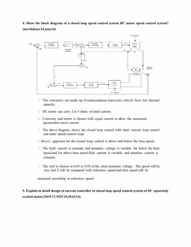
1. Derive the transfer function of separately excited dc motor.(17nov,16may,15nov,14nov)
Derivation of Transfer Functions
2.Design procedure of speed control? ( 17Nov,16may,15nov)

464
P controller PI controller
3. Draw the circuit diagram and explain the operation of closed loop control with inner-
current loop and field weakening?(nov16,may14)
The motor is driving a load which is proportional to friction. The output
of the tachogenerator is filtered to remove the ripples to provide the
mr r*) is feedback signal which is
mr) to produce a speed error signal. This
signal is processed through a Proportional plus Integral (PI) controller to
determine the torque command (Te*). The torque command is limited, to keep it
within the safe current limits and the current command is obtained by proper
scaling. The armature current loop signal ia * is compared to the feedback
armature current ia to have a zero current error. If there is an error, a PI current
controller processes it to alter the control signal Vc. The control signal
accordingly modifies the triggering for
implementation.

The inner current loop ensures a fast current response and also limits the
current to a safe preset level. This inner current loop makes the converter a linear current
amplifier. The outer speed loop ensures that the actual speed is always equal to the
commanded speed and that any transient is overcome within the shortest feasible time
without exceeding the motor and converter capacity. The operation of closed loop
speed controlled drive is explained from one or two particular instances of speed
command. A speed from zero to rated value is obtained and the motor is assumed to
be at standstill which will generate a large speed error and a torque command and in
turn an armature current command. The armature current error will generate the
triggering angle to supply a preset maximum dc voltage across the motor terminals.
The inner current loop will maintain the current at a level permitted by its
command value, producing a corresponding torque. As the motor starts running, the
torque and current are maintained at their maximum level, thus accelerating the motor
rapidly. When the rotor attains the command value, the torque command will settle down
to a value equal to the sum of load torque and other motor losses to keep the motor
performance in steady state. The design of the gain and time constant of the speed and
current controllers is of paramount importance in meeting the dynamic specifications
of the motor drives.
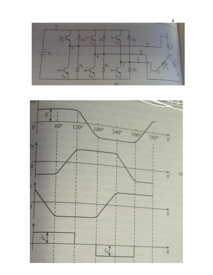
4. Show the block diagram of a closed loop speed control system DC motor speed control system?
(nov16&nov15,may14)
The converters are made up of semiconductor materials, which have low thermal capacity.
DC motor can carry 2 to 3 times of rated current.
Converter and motor is chosen with equal current to allow the maximum permissible rated current.
The above diagram shows the closed loop control with inner current loop control and outer speed control loop.
Ba s i c approach for the closed loop control is above and below the base speed.
The field current is constant and armature voltage is variable for below the base speed and for above base speed field current is variable and armature current is constant.
The emf is chosen as 0.85 or 0.95 of the rated armature voltage. The speed will be very and it will be compared with reference speed and then speed will be
increased according to reference speed
5. Explain in detail design of current controller of closed loop speed control system of DC separately
excited motor.(NOV17,NOV15,MAY14)

Procedure
Design the torque loop (fastest) first.
Design the speed loop assuming the torque loop
to be ideal.
Design the position loop (slowest) assuming the
speed loop to be ideal.
6. Derive the transfer function of DC motor load system with armature voltage control?
(nov17,may14,may13,nov12)
The speed is directly proportional to the voltage applied across the armature. As the supply
voltage is normally constant, the voltage across the armature can be controlled by adding a variable
resistance in series with the armature as shown in the Fig. 1.
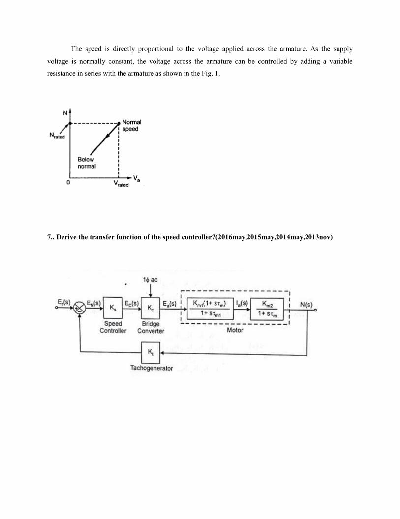
7.. Derive the transfer function of the speed controller?(2016may,2015may,2014may,2013nov)

8. Explain in detail about closed loop armature and field weakening mode in speed control of dc motor.(nov15&may14,may12)

o Converter and motor is chosen with equal current to allow the maximum permissible rated current.
o The above diagram shows the closed loop control with inner current loop control and outer speed control loop.
o Bas i c approach for the closed loop control is above and below the base speed.o The field current is constant and armature voltage is variable for below the base
speed and for above base speed field current is variable and armature current is constant.
9. Give the design procedure of current controller?(nov17,may15,may13)
10. Converter selection and characteristics (17nov, 15may, 13nov,12nov,11nov)


![Dhanalakshmi Project[1]](https://static.fdocuments.in/doc/165x107/550055ad4a7959da6c8b50dd/dhanalakshmi-project1.jpg)