DHANALAKSHMI COLLEGE OF ENGINEERING, CHENNAI · DHANALAKSHMI COLLEGE OF ENGINEERING, CHENNAI ......
19
DHANALAKSHMI COLLEGE OF ENGINEERING, CHENNAI Department of Computer Science and Engineering CS6502 - OBJECT ORIENTED ANALYSIS AND DESIGN 2 & 16 Mark Questions & Answers Year / Semester: III / V Regulation: 2013 Academic year: 2017 - 2018 –
Transcript of DHANALAKSHMI COLLEGE OF ENGINEERING, CHENNAI · DHANALAKSHMI COLLEGE OF ENGINEERING, CHENNAI ......

DHANALAKSHMI COLLEGE OF ENGINEERING, CHENNAI
Department of Computer Science and Engineering
CS6502 - OBJECT ORIENTED ANALYSIS AND DESIGN
2 & 16 Mark Questions & Answers
Year / Semester: III / V
Regulation: 2013
Academic year: 2017 - 2018
–

UNIT IV
PART A
1. What is the system sequence diagram? Mention its use.
(A/M-11) (M/J-12)(N/D-11) (2Marks)
A system sequence diagram (SSD) is a picture that shows, for a particular scenario of a use case,
the events that external actors generate their order, and inter-system events. All systems are treated
as a black box; the emphasis of the diagram is events that cross the system boundary from actors to
systems.
2. What is meant by sequence number in UML? Where and for what it is used?
(N/D-11) (2 Marks)
Sequence number can be of:
Automatic - Sequence numbers of messages will be updated automatically after you moved the
messages, and you cannot specify custom sequence number to messages.
Manual - Sequence numbers of messages will not be updated even after you moved the
messages, and you can specify custom sequence number to messages.
Uses:
Trace external interactions with the software
Plan the internal behavior of the application
Study the software structure
View the system architecture
Trace behavior down to physical components
3. List the relationships used in class diagram. (A/M-11) (2 Marks)
Category
Function
Activity edges Represent the flow between activities
Associations Indicate that instances of one model element are connected to instances of
another model element
Dependencies Indicate that a change to one model element can affect another model
element
Generalizations Indicate that one model element is a specialization of another model element
Realizations Indicate that one model element provides a specification that another model
element implements
Transitions Represent changes in state
4. What is meant by system behavior? (2 Marks)
System behavior is a description of what a system does, without explaining how it does it. One
Part of that description is a system sequence diagram. Other parts include the Use cases, and system

contracts.
5. What is meant by inter-system SSDs? (2 Marks)
SSDs can also be used to illustrate collaborations between systems, such as between the Next Gen
POS and the external credit payment authorizer. However, this is deferred until a later iteration in the
case study, since this iteration does not include remote systems collaboration.
6. Define – System Events, System Boundary (2 Marks)
To identify system events, it is necessary to be clear on the choice of system boundary, as
discussed in the prior chapter on use cases. For the purposes of software development, the system
boundary is usually chosen to be the software system itself; in this context, a system event is an
external event that directly stimulates the software.
7. Write short note on naming system events and operations. (2 Marks)
System events (and their associated system operations) should be expressed at the level of intent
rather than in terms of the physical input medium or interface widget level.
It also improves clarity to start the name of a system event with a verb Thus "enter item" is better
than "scan" (that is, laser scan) because it captures the intent of the operation while remaining abstract
and noncommittal with respect to design choices about what interface is used to capture the system
event.
8. Define – Package (M/J- 12) (2 Marks)
A package groups and manages the modelling elements, such as classes, their associations, and
their structures. Packages themselves may be nested within other packages. A package may contain
both other packages and ordinary model elements. The entire system description can be thought of as a
single high-level sub-system package with everything else init. All kinds of UML model elements and
diagrams can be organized into packages.
9. What are interactive diagrams? List the components involved in interactive diagrams.
(N/D-12) (2 Marks)
Interaction diagrams are diagrams that describe how groups of objects collaborate to get the job
done interaction diagrams capture the behavior of the single use case, showing the pattern of
interaction among objects.
There are two kinds of interaction models,
• Sequence Diagram
• Collaboration Diagram.
10. What are the uses of UML component diagram? (A/M-10)(2 Marks)
The uses of UML component diagram are:
Model the components of a system.
Model database schema.
Model executables of an application.
Model system's source code.
11. What is Software Architecture? (2 Marks)
An architecture is the set of significant decisions about the organization of a software system, the
selection of the structural elements and their interfaces by which the system is composed, together

with their behavior as specified in the collaborations among those elements, the composition of
these structural and behavioral elements into progressively larger subsystems, and the architectural
style that guides this organization these elements and their interfaces, their collaborations, and their
composition.
12. What is a layer? (2 Marks)
A layer is a very coarse-grained grouping of classes, packages, or subsystems that has cohesive
responsibility for a major aspect of the system. Also, layers are organized such that \"higher\" layers
(such as the UI layer) call upon services of \"lower\" layers, but not normally vice versa.
13. What are the UML Operations and method? (2 Marks)
A UML operation is a declaration, with a name, parameters, return type, exceptions list, and
possibly a set of constraints of pre-and post-conditions. But, it isn\'t an implementation rather,
methods are implementations.
A UML method is the implementation of an operation; if constraints are defined, the method must
satisfy them. A method may be illustrated several ways, including:
• In interaction diagrams, by the details and sequence of messages
• In class diagrams, with a UML note symbol stereotyped with «method»
14. What is the logical architecture? (2 Marks)
The logical architecture is the large-scale organization of the software classes into packages (or
namespaces), subsystems, and layers. It's called the logical architecture because there's no decision
about how these elements are deployed across different operating system processes or across physical
computers in a network.
15. Define − Classifier (2 Marks)
A UML classifier is a model element that describes behavioral and structure features. Classifiers
can also be specialized. They are a generalization of many of the elements of the UML, including
classes, interfaces, use cases, and actors. In class diagrams, the two most common classifiers are
regular classes and interfaces.
16. What are the connection between SSDs, system operations, and layers? (2 Marks)
The SSDs illustrate these system operations, but hide the specific UI objects. Nevertheless,
normally it will be objects in the UI layer of the system that capture these system operation requests,
usually with a rich client GUI or Web page.
17. What are UML properties and property strings? (2 Marks)
In the UML, a property is a named value denoting a characteristic of an element. A property has
semantic impact. Some properties are predefined in the UML, such as visibility a property of an
operation. Others can be user-defined.
Properties of elements may be presented in many ways, but a textual approach is to use the UML
property string {name1=value1, name2=value2} format, such as {abstract, visibility=public}. Some
properties are shown without a value, such as {abstract}; this usually implies a boolean property,
shorthand for {abstract=true}. Note that {abstract} is both an example of a constraint and a property
string.

18. What is an association class? (2 Marks)
An association class allows you treat an association itself as a class, and model it with attributes,
operations, and other features. For example, if a Company employs many Persons, modelled with an
Employs association, you can model the association itself as the Employment class, with attributes
such as startDate.
19. List the relationships used in class diagram? (M/J - 12)(2 Marks) The following are the relationships used in class diagram:
1. Generalization(class to class)
2. Association (object to object)
3. Aggregation (object to object)
4. Composition (object to object)
20. What is design class diagram (DCD)? (2 Marks)
It can explored, the same UML diagram can be used in multiple perspectives (Figure below). In a
conceptual perspective the class diagram can be used to visualize a domain model. A unique term to
clarify when the class diagram is used in software or design perspective is called design class diagram
(DCD), and all DCDs form part of the Design Model.
21. How to show methods in class diagrams? (2 Marks)
A UML method is the implementation of an operation; if constraints are defined, the method must
satisfy them. A method may be illustrated several ways, including: in interaction diagrams, by the
details and sequence of messages in class diagrams, with a UML note symbol stereotyped with
«method».
22. Define – Keywords, Stereotype, Profiles and Tags (2 Marks)
Keywords, stereotypes are shown with guillemot’s symbols, such as «authorship». But, they are
not keywords, which can be confusing. A stereotype represents a refinement of an existing modelling
concept and is defined within a UML profile—informally, a collection of related stereotypes, tags, and
constraints to specialize the use of the UML for a specific domain or platform, such as a UML profile
for project management or for data modelling. The UML predefines many stereotypes, such as
«destroy» (used on sequence diagrams), and also allows user-defined ones. Thus, stereotypes provide
an extension mechanism in the UML.
23. What is the use of interaction diagram? (M/J – 13) (2 Marks)
The term interaction diagram is a generalization of two more specialized UML diagram types;
both can be used to express similar message interactions:
Collaboration diagrams
Sequence diagrams
24. What is meant by link? (2 Marks)
A link is a connection path between two objects; it indicates some form of navigation and
visibility between the objects is possible. More formally, a link is an instance of an association. For
example, there is a link or path of navigation from a Register to a Sale, along which messages may
flow, such as the make 2 Payment message.
Each message between objects is represented with a message expression and small arrow
indicating the direction of the message. Many messages may flow along this link. A sequence number

is added to show the sequential order of messages in the current thread of control.
25. What is an instance? (2
Marks)
Any message can be used to create an instance, but there is a convention in the UML to
use a message named create for this purpose. If another (perhaps less obvious) message
name is used, the message may be annotated with a special feature called a UML stereotype,
like so: «create».
The create message may include parameters, indicating the passing of initial values.
This indicates, for example, a constructor call with parameters in Java.

PART B
1. Explain in detail, the System Sequence Diagrams.
If the lifeline is that of an object, it demonstrates a role. Leaving the instance name blank
can represent anonymous and unnamed instances.
Messages, written with horizontal arrows with the message name written above them,
display interaction. Solid arrow heads represent synchronous calls, open arrow heads represent
asynchronous messages, and dashed lines represent reply messages. If a caller sends a synchronous message, it must wait until the message is done, such as invoking a
subroutine. If a caller sends an asynchronous message, it can continue processing and doesn’t have
to wait for a response. Asynchronous calls are present in multithreaded applications and in message-oriented
middleware. Activation boxes, or method-call boxes, are opaque rectangles drawn on top of
lifelines to represent that processes are being performed in response to the message (Execution
Specifications in UML).
Objects calling methods on themselves use messages and add new activation boxes on top
of any others to indicate a further level of processing.
When an object is destroyed (removed from memory), an X is drawn on top of the lifeline,
and the dashed line ceases to be drawn below it (this is not the case in the first example though). It
should be the result of a message, either from the object itself, or another.
A message sent from outside the diagram can be represented by a message originating from
a filled-in circle (found message in UML) or from a border of the sequence diagram (gate in UML).
UML has introduced significant improvements to the capabilities of sequence diagrams.
Most of these improvements are based on the idea of interaction fragments[2] which represent
smaller pieces of an enclosing interaction. Multiple interaction fragments are combined to create a
variety of combined fragments,[3] which are then used to model interactions that include
parallelism, conditional branches, optional interactions.
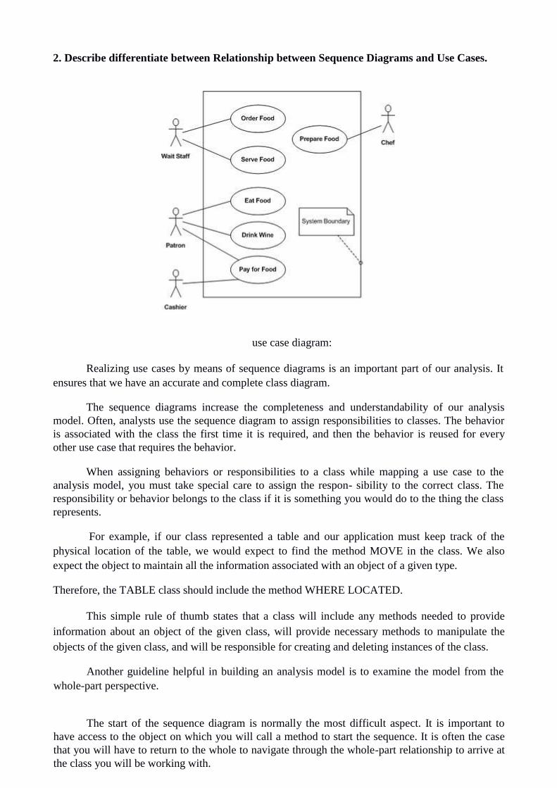
2. Describe differentiate between Relationship between Sequence Diagrams and Use Cases.
use case diagram:
Realizing use cases by means of sequence diagrams is an important part of our analysis. It
ensures that we have an accurate and complete class diagram.
The sequence diagrams increase the completeness and understandability of our analysis
model. Often, analysts use the sequence diagram to assign responsibilities to classes. The behavior
is associated with the class the first time it is required, and then the behavior is reused for every
other use case that requires the behavior.
When assigning behaviors or responsibilities to a class while mapping a use case to the
analysis model, you must take special care to assign the respon- sibility to the correct class. The
responsibility or behavior belongs to the class if it is something you would do to the thing the class
represents.
For example, if our class represented a table and our application must keep track of the
physical location of the table, we would expect to find the method MOVE in the class. We also
expect the object to maintain all the information associated with an object of a given type. Therefore, the TABLE class should include the method WHERE LOCATED.
This simple rule of thumb states that a class will include any methods needed to provide
information about an object of the given class, will provide necessary methods to manipulate the
objects of the given class, and will be responsible for creating and deleting instances of the class.
Another guideline helpful in building an analysis model is to examine the model from the
whole-part perspective.
The start of the sequence diagram is normally the most difficult aspect. It is important to
have access to the object on which you will call a method to start the sequence. It is often the case
that you will have to return to the whole to navigate through the whole-part relationship to arrive at
the class you will be working with.

A simple example illustrates the whole-part relationship navigation. Suppose you were
asked to read the first paragraph of three chapters of a book. First, you would need to know where
to go to get the book. We might state that all books we are referring to are available at the Fourth
St. library.
4. Explain in detail, the Logical Architecture and Package Diagram.
Logical Architecture and UML Package Diagrams...
• High level, large scale Architecture Model.
• At this level, the design of a typical OO system is based on several architectural layers, such as a UI layer, an application logic (or "domain") layer, and so forth. • Goal is to design a logical architecture with layers and partitions using UML package diagrams
Logical Architecture And Layers
• Logical architecture is the large-scale organization of the software classes into packages (or
namespaces), subsystems, and layers. • Logical - because there's no decision about how these elements are deployed across different
operating system processes or across physical computers in a network (deployment architecture)
• Logical architecture is the large-scale organization of the software classes into packages (or
namespaces), subsystems, and layers.
• It’s called the logical architecture because there’s no decision about how these elements are
deployed across different operating system processes or across physical computers in a network
(these latter decisions are part of the deployment architecture )
LOGICAL ARCHITECTURE REFINEMENT :
UML CLASS DIAGRAM:
The class diagram is the main building block of object oriented modelling. It is used both for
general conceptual modelling of the systematics of the application, and for detailed modelling
translating the models into programming code. Class diagrams can also be used for data modeling.

The classes in a class diagram represent both the main objects, interactions in the application
and the classes to be programmed.
The top part contains the name of the class. It is printed in bold and centered, and the first
letter is capitalized. The middle part contains the attributes of the class. They are left-aligned and the first
letter is lowercase.
The bottom part contains the methods the class can execute. They are also left-aligned and
the first letter is lowercase.
In the design of a system, a number of classes are identified and grouped together in a class
diagram which helps to determine the static relations between those objects. With detailed
modelling, the classes of the conceptual design are often split into a number of subclasses. A Link is the basic relationship among objects.
Association
An association represents a family of links. A binary association (with two ends) is normally
represented as a line. An association can link any number of classes. An association with three links
is called a ternary association. An association can be named, and the ends of an association can be
adorned with role names, ownership indicators, multiplicity, visibility, and other properties.
There are four different types of association: bi-directional, uni-directional, Aggregation
(includes Composition aggregation) and Reflexive. Bi-directional and uni-directional associations
are the most common ones. For instance, a flight class is associated with a plane class bi-
directionally. Association represents the static relationship shared among the objects of two classes.
Aggregation
Aggregation is a variant of the "has a" association relationship; aggregation is more specific
than association. It is an association that represents a part-whole or part-of relationship. As shown in
the image, a Professor 'has a' class to teach. As a type of association, an aggregation can be named
and have the same adornments that an association can. However, an aggregation may not involve
more than two classes; it must be a binary association.
Aggregation can occur when a class is a collection or container of other classes, but the
contained classes do not have a strong lifecycle dependency on the container. The contents of the
container are not automatically destroyed when the container is.
In UML, it is graphically represented as a hollow diamond shape on the containing class
with a single line that connects it to the contained class. The aggregate is semantically an extended
object that is treated as a unit in many operations, although physically it is made of several lesser
objects.
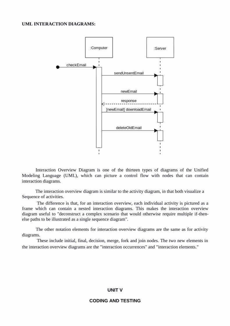
UML INTERACTION DIAGRAMS:
Interaction Overview Diagram is one of the thirteen types of diagrams of the Unified
Modeling Language (UML), which can picture a control flow with nodes that can contain
interaction diagrams.
The interaction overview diagram is similar to the activity diagram, in that both visualize a
Sequence of activities. The difference is that, for an interaction overview, each individual activity is pictured as a
frame which can contain a nested interaction diagrams. This makes the interaction overview
diagram useful to "deconstruct a complex scenario that would otherwise require multiple if-then-
else paths to be illustrated as a single sequence diagram".
The other notation elements for interaction overview diagrams are the same as for activity
diagrams. These include initial, final, decision, merge, fork and join nodes. The two new elements in
the interaction overview diagrams are the "interaction occurrences" and "interaction elements."
UNIT V
CODING AND TESTING


1. Explain in detail, the Object Oriented Testing Strategies.
While there are efforts underway to develop more automated testing processes from test
models of the object model characteristics (for example states, data flows, or associations), testing
is still based on the creation of test cases and test data by team members using a structural (White
Box Testing) and/or a functional (SeeBlack Box Testing) strategy.
Overview of Object Orientated Unit Testing
Implications of Object Oriented Testing
Once a class is testing thoroughly it can be reused without being unit tested again
UML class state charts can help with selection of test cases for classes
Classes easily mirror units in traditional software testing
Objective of OO is to facilitate easy code reuse in the form of classes
To allow this each class has to be rigiriously unit tested
Due to classes potentially used in unforeseeable ways when composed in new systems
Example: A XML parser for a web browser
Classes must be created in a way promoting loose coupling and strong cohesion
CLASS TESTING:
Class testing is testing that ensures a class and its instances (objects) perform as defined.
(Source: Object Testing Patterns).
When designing a society of classes, an excellent goal is to structure classes so they
can be tested with a minimum of fuss. After all, a class that requires compiling the application, starting the application, logging into the application, navigating to a particular point in the application ...will likely not get rigorously tested.
In computer programming, unit testing is a software testing method by which individual

units of source code, sets of one or more computer program modules together with
associated control data, usage procedures, and operating procedures, are tested to
determine whether they are fit for use.
Intuitively, one can view a unit as the smallest testable part of an application. In
procedural programming, a unit could be an entire module, but it is more commonly an
individual function or procedure.
In object-oriented programming, a unit is often an entire interface, such as a class,
but could be an individual method.
Unit tests are short code fragments created by programmers or occasionally by white
box testers during the development process. It forms the basis for component testing.
Ideally, each test case is independent from the others. Substitutes such as method stubs,
mock objects,[5] fakes, and test harnesses can be used to assist testing a module in
isolation. Unit tests are typically written and run by software developers to ensure that
code meets its design and behaves as intended.
OO INTEGRATION TESTING:
Research confirms that testing methods proposed for procedural approach are not
adequate for OO approach Ex. Statement coverage
OO software testing poses additional problems due to the distinguishing
characteristics of OO Ex. Inheritance
Testing time for OO software found to be increased compared to testing procedural software
Typical OO software characteristics that impact testing ...
State dependent behavior Encapsulation Inheritance Polymorphism and dynamic Binding Abstract and generic classes Exception handling Procedural software
unit = single program, function, or procedure Object oriented software unit = class unit testing =intra-class testing integration testing = inter-class testing
cluster of classes dealing with single methods separately is usually too expensive (complex
scaffolding), so methods are usually tested in the context of the class they belong to.

2. Describe in detail, the GUI Testing and OO System Testing.
Overview
� This chapter discusses the testing of object-oriented systems. The process of testing object-
oriented systems begins with a review of the object-oriented analysis and design models. Once
the code is written object-oriented testing (OOT) begins by testing "in the small" with class
testing (class operations and collaborations). As classes are integrated to become subsystems
class collaboration problems are investigated. Finally, use-cases from the OOA model are used
to uncover software validation errors.
� OOT similar to testing conventional software in that test cases are developed to exercise the
classes, their collaborations, and behavior.
� OOT differs from conventional software testing in that more emphasis is placed assessing the
completeness and consistency of the OOA and OOD models as they are built.
� OOT tends to focus more on integration problems than on unit testing.
Object-Oriented Testing Activities
� Review OOA and OOD models
� Class testing after code is written
� Integration testing within subsystems
� Integration testing as subsystems are added to the system
� Validation testing based on OOA use-cases
Testing OOA and OOD Models
� OOA and OOD cannot be tested but can review the correctness and consistency.
� Correctness of OOA and OOD models
Syntactic Semantic
Judged by ensuring
that proper modeling
conventions and symbolism have been
used
Based on the
model's conformance
to the real world
problem domain
� Consistency of OOA and OOD Models

x Assess the class-responsibility-collaborator (CRC) model and object-relationship diagram
x Review system design (examine the object-behavior model to check mapping of system
behavior to subsystems, review concurrency and task allocation, use use-case scenarios
to exercise user interface design) x Test object model against the object relationship network to ensure that all design object
contain necessary attributes and operations needed to implement the collaborations
defined for each CRC card
x Review detailed specifications of algorithms used to implement operations
using conventional inspection techniques
� Object-Oriented Testing Strategies
� Unit testing in the OO context
x Smallest testable unit is the encapsulated class or object x Similar to system testing of conventional software
x Do not test operations in isolation from one another
x Driven by class operations and state behavior, not algorithmic detail and data flow
across module interface
x Complete test coverage of a class involves
- Testing all operations associated with an object - Setting and interrogating all object attributes
- Exercising the object in all possible states
x Design of test for a class uses a verity of methods:
- fault-based testing - random testing
- partition testing
x each of these methods exercises the operations encapsulated by the class x test sequences are designed to ensure that relevant operations are exercised
x state of the class (the values of its attributes) is examined to determine if errors exist
� Integration testing in the OO context
focuses on groups of classes that collaborate or communicate in some manner
integration of operations one at a time into classes is often meaningless
thread-based testing (testing all classes required to respond to one system input or event)
use-based testing (begins by testing independent classes first and the dependent classes
that make use of them)
cluster testing (groups of collaborating classes are tested for interaction errors)
regression testing is important as each thread, cluster, or subsystem is added to the
system Levels of integration are less distinct in object-oriented systems
� Validation testing in the OO context
x focuses on visible user actions and user recognizable outputs from the system
x validation tests are based on the use-case scenarios, the object-behavior model, and the
event flow diagram created in the OOA model x conventional black-box testing methods can be used to drive the validation tests
3.Describe in detail the Test Case Design for OO Software.
� Each test case should be uniquely identified and be explicitly associated with a class to be
tested
� State the purpose of each test
� List the testing steps for each test including:
x list of states to test for each object involved in the test x list of messages and operations to exercised as a consequence of the test
x list of exceptions that may occur as the object is tested
x list of external conditions needed to be changed for the test
x supplementary information required to understand or implement the test
� Testing Surface Structure and Deep Structure
x Testing surface structure (exercising the structure observable by end-user, this often
involves observing and interviewing users as they manipulate system objects) x Testing deep structure (exercising internal program structure - the dependencies,
behaviors, and communications mechanisms established as part of the system and object
design)
� Testing Methods Applicable at The Class Level
Random testing - requires large numbers data permutations and combinations, and can be
inefficient
o Identify operations applicable to a class o Define constraints on their use o Identify a minimum test sequence o Generate a variety of random test sequences.
Partition testing - reduces the number of test cases required to test a class
o state-based partitioning - tests designed in way so that operations that cause state
changes are tested separately from those that do not. o attribute-based partitioning - for each class attribute, operations are classified according
to those that use the attribute, those that modify the attribute, and those that do not use or modify the attribute
o category-based partitioning - operations are categorized according to the function they perform: initialization, computation, query, termination

� Fault-based testing
x best reserved for operations and the class level uses the inheritance structure x tester examines the OOA model and hypothesizes a set of plausible defects that may be
encountered in operation calls and message connections and builds appropriate test cases x misses incorrect specification and errors in subsystem interactions
� Inter-Class Test Case Design
x Test case design becomes more complicated as integration of the OO system begins –
testing of collaboration between classes
x Multiple class testing
o for each client class use the list of class operators to generate random test sequences that
send messages to other server classes
o for each message generated determine the collaborator class and the corresponding server object operator
o for each server class operator (invoked by a client object message) determine the message it transmits
o for each message, determine the next level of operators that are invoked and incorporate them into the test sequence
x Tests derived from behavior models
o Use the state transition diagram (STD) as a model that represent the dynamic behavior of
a class. o test cases must cover all states in the STD
o breadth first traversal of the state model can be used (test one transition at a time and only make use of previously tested transitions when testing a new transition)
o test cases can also be derived to ensure that all behaviors for the class have been adequately exercised
� Testing Methods Applicable at Inter-Class Level
Cluster Testing
Is concerned with integrating and testing clusters of cooperating objects Identify clusters using knowledge of the operation of objects and the system features that
are implemented by these clusters
x Approaches to Cluster Testing
o Use-case or scenario testing � Testing is based on a user interactions with the system
� Has the advantage that it tests system features as experienced by users
o Thread testing – tests the systems response to events as processing threads through the system
o Object interaction testing – tests sequences of object interactions that stop when an object operation does not call on services from another object

Use Case
Scenario-based Testing x Based on
o use cases o corresponding sequence diagrams
x Identify scenarios from use-cases and supplement these with interaction diagrams that show
the objects involved in the scenario x Concentrates on (functional)
requirements o Every use case o Every fully expanded extension (<<extend>>) combination
o Every fully expanded uses (<<uses>>) combination o Tests normal as well as exceptional behavior
x A scenario is a path through sequence diagram x Many different scenarios may be associated with a sequence diagram
x using the user tasks described in the use-cases and building the test cases from the tasks
and their variants
x uncovers errors that occur when any actor interacts with the OO software
x concentrates on what the use does, not what the product does
x you can get a higher return on your effort by spending more time on reviewing the use-
cases as they are created, than spending more time on use-case testing
� OO Test Design Issues
� White-box testing methods can be applied to testing the code used to implement
class operations, but not much else
� Black-box testing methods are appropriate for testing OO systems
� Object-oriented programming brings additional testing concerns
x classes may contain operations that are inherited from super classes x subclasses may contain operations that were redefined rather than inherited x all classes derived from an previously tested base class need to be thoroughly tested