DGS-PU-310-Rev-0
19
Abu Dhabi Oil Refining Company PIPELINE BALL VALVES DGS-PU-310 Rev-0 March 2006 Takreer DGS-PU-310-Rev-0 March-2006 Printed 20-Apr-09 08:47:10 Initials Page 1 of 19 PIPELINE BALL VALVES Amendment History No Date Amendment Description Proposed Approved Incorporated DGS History 0 March 2006 DGS-PU-310-Rev-0 Previous Project / Lessons Learnt Incorporated AH/DDC ETSDM / EPDM No Date Description Source Reviewed Approved DGS-PU-310 Rev-0
-
Upload
bobbi-middleton -
Category
Documents
-
view
7 -
download
1
description
DGS-PU-310-Rev-0
Transcript of DGS-PU-310-Rev-0

Abu Dhabi Oil Refining Company
PIPELINE BALL VALVES DGS-PU-310 Rev-0 March 2006
Takreer DGS-PU-310-Rev-0 March-2006 Printed 20-Apr-09 08:47:10 Initials Page 1 of 19
PIPELINE BALL VALVES
Amendment History
No Date Amendment Description Proposed Approved Incorporated
DGS History
0 March 2006 DGS-PU-310-Rev-0 Previous Project / Lessons Learnt Incorporated
AH/DDC ETSDM / EPDM
No Date Description Source Reviewed Approved
DGS-PU-310 Rev-0
Abu Dhabi Oil Refining Company
PIPELINE BALL VALVES DGS-PU-310 Rev-0 March 2006
Takreer DGS-PU-310-Rev-0 March-2006 Printed 20-Apr-09 08:47:10 Initials Page 2 of 19
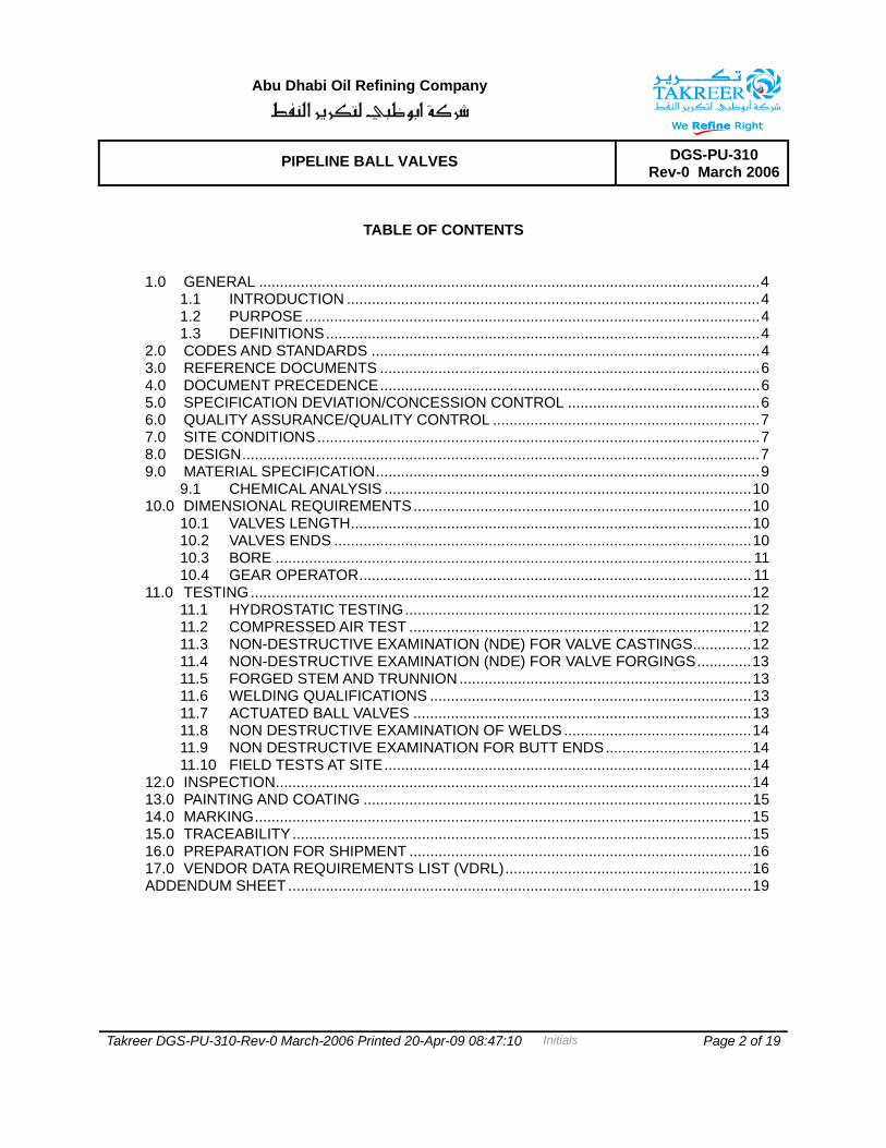
TABLE OF CONTENTS
1.0 GENERAL ........................................................................................................................4 1.1 INTRODUCTION ...................................................................................................4 1.2 PURPOSE .............................................................................................................4 1.3 DEFINITIONS........................................................................................................4
2.0 CODES AND STANDARDS .............................................................................................4 3.0 REFERENCE DOCUMENTS ...........................................................................................6 4.0 DOCUMENT PRECEDENCE...........................................................................................6 5.0 SPECIFICATION DEVIATION/CONCESSION CONTROL ..............................................6 6.0 QUALITY ASSURANCE/QUALITY CONTROL ................................................................7 7.0 SITE CONDITIONS..........................................................................................................7 8.0 DESIGN............................................................................................................................7 9.0 MATERIAL SPECIFICATION............................................................................................9
9.1 CHEMICAL ANALYSIS ........................................................................................10 10.0 DIMENSIONAL REQUIREMENTS.................................................................................10
10.1 VALVES LENGTH................................................................................................10 10.2 VALVES ENDS ....................................................................................................10 10.3 BORE .................................................................................................................. 11 10.4 GEAR OPERATOR.............................................................................................. 11
11.0 TESTING........................................................................................................................12 11.1 HYDROSTATIC TESTING...................................................................................12 11.2 COMPRESSED AIR TEST ..................................................................................12 11.3 NON-DESTRUCTIVE EXAMINATION (NDE) FOR VALVE CASTINGS..............12 11.4 NON-DESTRUCTIVE EXAMINATION (NDE) FOR VALVE FORGINGS.............13 11.5 FORGED STEM AND TRUNNION......................................................................13 11.6 WELDING QUALIFICATIONS .............................................................................13 11.7 ACTUATED BALL VALVES .................................................................................13 11.8 NON DESTRUCTIVE EXAMINATION OF WELDS .............................................14 11.9 NON DESTRUCTIVE EXAMINATION FOR BUTT ENDS...................................14 11.10 FIELD TESTS AT SITE........................................................................................14
12.0 INSPECTION..................................................................................................................14 13.0 PAINTING AND COATING .............................................................................................15 14.0 MARKING.......................................................................................................................15 15.0 TRACEABILITY..............................................................................................................15 16.0 PREPARATION FOR SHIPMENT ..................................................................................16 17.0 VENDOR DATA REQUIREMENTS LIST (VDRL)...........................................................16 ADDENDUM SHEET ...............................................................................................................19
Abu Dhabi Oil Refining Company
PIPELINE BALL VALVES DGS-PU-310 Rev-0 March 2006
Takreer DGS-PU-310-Rev-0 March-2006 Printed 20-Apr-09 08:47:10 Initials Page 3 of 19
List of Authorized Signatures/ Initials
DGS Discipline Committee Member, ADRD ------------------------------
DGS Discipline Committee Member, RRD ------------------------------
DGS Discipline Committee Member Leader, E&PD Abdul Hakim (AH)
Engineering & Technical Services Manager, E&PD Quazi Abdul Matin (QAM)
Engineering & Projects Division Manager, E&PD Mohamed Al Yabhouni (MAY)

Abu Dhabi Oil Refining Company
PIPELINE BALL VALVES DGS-PU-310 Rev-0 March 2006
Takreer DGS-PU-310-Rev-0 March-2006 Printed 20-Apr-09 08:47:10 Initials Page 4 of 19
1.0 GENERAL
1.1 INTRODUCTION
This specification gives minimum technical requirements for design, manufacture, testing, supply, performance of ball valves in sizes two inch (nominal) and larger for class rating up to ANSI 900# for use in onshore liquid hydrocarbon pipelines.
1.2 PURPOSE
This specification supplements the codes listed in Section 2.0 of this specification, the equipment specifications, equipment data sheets, and drawings.
1.3 DEFINITIONS
For the purpose of this specification, the following definitions shall apply:
1.3.1 CONCESSION REQUEST - A deviation requested by the CONTRACTOR / SUBCONTRACTOR or VENDOR / SUBVENDOR, usually after receiving the contract package or purchase order. Often, it refers to an authorisation to use, repair, recondition, reclaim, or release materials, components, or equipment already in progress or completely manufactured but which does not meet or comply with COMPANY requirements. A CONCESSION REQUEST is subject to COMPANY approval.
1.3.2 SHALL - The use of the word “shall” indicates a mandatory requirement.
1.3.3 SHOULD - The use of the word “should” indicates a strong recommendation to comply with the requirements of this document.
2.0 CODES AND STANDARDS
It shall be the CONTRACTOR’s, VENDOR’s, SUBCONTRACTOR’s and or SUBVENDOR’s responsibility to be or to become knowledgeable of the requirements of the referenced codes and standards.
The following codes and standards, to the extent specified herein, form a part of this specification. When an edition date is not indicated for a code or standard, the latest edition in force at the time of contract award shall apply.
American Society of Mechanical Engineers (ASME)
ASME B 16.5 Pipe Flanges and Flanged Fittings
ASME B 16.10 Face-to-Face and End-to-End Dimensions of Valves
ASME B 16.34 Valves - Flanged, Threaded, and Welding End

Abu Dhabi Oil Refining Company
PIPELINE BALL VALVES DGS-PU-310 Rev-0 March 2006
Takreer DGS-PU-310-Rev-0 March-2006 Printed 20-Apr-09 08:47:10 Initials Page 5 of 19
ASME B 31.4 Pipeline Transportation System for Liquid Hydrocarbons and Other Liquids
ASME BPV Section IX Boiler and Pressure Vessel Code, Welding and Brazing Qualifications
ASME B 31.3 Process Piping
American Petroleum Institute (API)
API 5L Specification for Line Pipe
API 6D Specification for Pipeline Valves
API STD 598 Valve Inspection and Test
API 607 Fire test for Soft Seated Quarter-turn Valves
API 6FA Fire Test for Valves
API 1104 Standard for Welding Pipelines and Related Facilities.
American Society for Testing and Materials (ASTM)
ASTM A 105 Forgings, Carbon Steel for Piping Components
ASTM A 181 Forged or Rolled Steel Pipe Flanges, Forged Fittings and Valves and Parts for General Service
ASTM A 216 Standard specification for steel castings, carbon, suitable for fusion welding, for high temperature service.
International Standard Organization
ISO 9001-2000 Quality Management System Requirements
ISO 9004-2000 Quality Management Guidelines for Performance Improvement System
ISO 9011 Guidelines for Quality and/or Environmental System Auditing
ISO 10474 Steel and Steel Product inspection documents
Manufacturers Standardization Society of the Valve and Fittings Industry (MSS)
MSS SP-6 Standard Finishes for Contact Faces of Pipe Flanges and Connecting End Flanges of Valves and Fittings
Abu Dhabi Oil Refining Company
PIPELINE BALL VALVES DGS-PU-310 Rev-0 March 2006
Takreer DGS-PU-310-Rev-0 March-2006 Printed 20-Apr-09 08:47:10 Initials Page 6 of 19
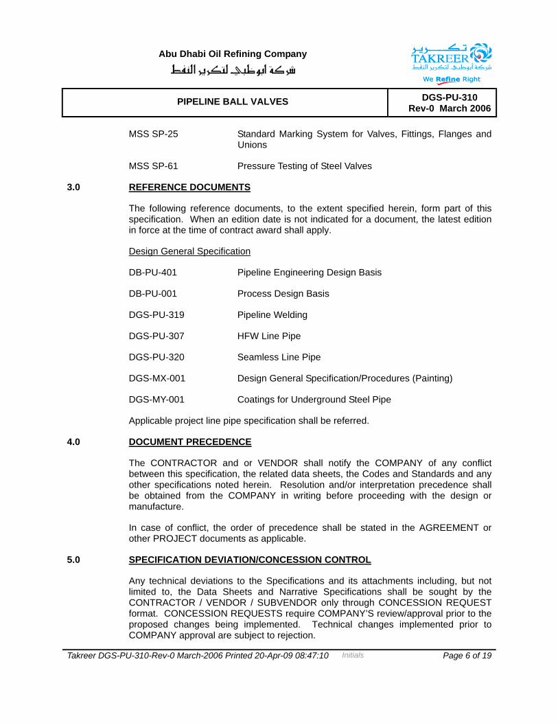
MSS SP-25 Standard Marking System for Valves, Fittings, Flanges and Unions
MSS SP-61 Pressure Testing of Steel Valves
3.0 REFERENCE DOCUMENTS
The following reference documents, to the extent specified herein, form part of this specification. When an edition date is not indicated for a document, the latest edition in force at the time of contract award shall apply.
Design General Specification
DB-PU-401 Pipeline Engineering Design Basis
DB-PU-001 Process Design Basis
DGS-PU-319 Pipeline Welding
DGS-PU-307 HFW Line Pipe
DGS-PU-320 Seamless Line Pipe
DGS-MX-001 Design General Specification/Procedures (Painting)
DGS-MY-001 Coatings for Underground Steel Pipe
Applicable project line pipe specification shall be referred.
4.0 DOCUMENT PRECEDENCE
The CONTRACTOR and or VENDOR shall notify the COMPANY of any conflict between this specification, the related data sheets, the Codes and Standards and any other specifications noted herein. Resolution and/or interpretation precedence shall be obtained from the COMPANY in writing before proceeding with the design or manufacture.
In case of conflict, the order of precedence shall be stated in the AGREEMENT or other PROJECT documents as applicable.
5.0 SPECIFICATION DEVIATION/CONCESSION CONTROL
Any technical deviations to the Specifications and its attachments including, but not limited to, the Data Sheets and Narrative Specifications shall be sought by the CONTRACTOR / VENDOR / SUBVENDOR only through CONCESSION REQUEST format. CONCESSION REQUESTS require COMPANY’S review/approval prior to the proposed changes being implemented. Technical changes implemented prior to COMPANY approval are subject to rejection.

Abu Dhabi Oil Refining Company
PIPELINE BALL VALVES DGS-PU-310 Rev-0 March 2006
Takreer DGS-PU-310-Rev-0 March-2006 Printed 20-Apr-09 08:47:10 Initials Page 7 of 19
6.0 QUALITY ASSURANCE/QUALITY CONTROL
VENDOR’S proposed quality system shall fully satisfy all the elements of ISO 9001 - 2000 and ISO 9004 - 2000. The quality system shall provide for the planned and systematic control of all quality-related activities performed during design, development, production, installation or servicing (as appropriate to the given system).
Implementation of the system shall be in accordance with the CONTRACTOR’S Quality Manual and Project Specific Quality Plan, which shall both together with all related/referenced procedures, be submitted to COMPANY for review, comment and approval as required by purchase/contract documents.
Material certification traceability shall be in accordance with paragraphs 15 and 17.
7.0 SITE CONDITIONS
Site conditions shall be in accordance with Process Design Basis, document number DB-PU-001.
8.0 DESIGN
8.1 Valve design shall meet the requirements of API Specification 6D and shall be suitable for the service conditions indicated in the Valve Data Sheets. The ASME Boiler and Pressure Vessel Code, Section VIII, Division 1 shall be used to design the valve body. Allowable stress requirements shall comply with the provisions of ASME B 31.3. In addition, corrosion allowance indicated in Valve Data Sheet shall be considered in valve design. However, the minimum wall thickness shall not be less than the minimum requirement of ASME B 16.34.
The manufacturer shall have valid licence to use API monogram on valves manufactured as per API 6D.
8.2 Valves shall be suitable for either buried or above ground installation as per the material requisition
8.3 Valves design shall be double block and bleed type.
8.4 Valves shall be of following designs:
All buried valves shall be of welded body design. Other above ground valves could be of top entry bolted body design. Valve body joints with threads are not permitted.
All ball valves shall be trunnion mounted type. Fire-safe design for all ball valves shall be as specified, in accordance with API 6FA. All ball valves shall be provided with double seat seals.
8.5 Ball valves shall be supplied with solid balls.

Abu Dhabi Oil Refining Company
PIPELINE BALL VALVES DGS-PU-310 Rev-0 March 2006
Takreer DGS-PU-310-Rev-0 March-2006 Printed 20-Apr-09 08:47:10 Initials Page 8 of 19
8.6 All valves shall have a vent and drain. Drain connection shall be at the lowest possible position on the valve body and vent connection at the highest possible position. Vent and drain shall be 1/2″ for valves up to 4″, 3/4″ for 6″ and 8″ and 1″ for 10″ to 20″. Body vent and drain shall be valved for sizes 6" & above and shall be of welded connection. Two valves shall be provided on the vent and drain connections. COMPANY may accept common vent and drain connection for valves up to 3" size. Vents/drain for valve size up to 4” shall be provided with suitable plug, which shall be seal welded at site after completion of field hydrotest.
8.7 Valves 6″ and above, shall be provided with secondary sealant injection to seats and stem seals. Design shall incorporate an internal non-return valve, fitted with plug or pipe cap. Valve design shall have a provision replace the sealant injection fitting under full line pressure.
8.8 The seat rings shall be spring energized to ensure sealing at low differential pressures. Design of seat ring and body shall be such that entrapment of any solid present in the fluid will not obstruct free movement of the seat rings and will not reduce spring action. Seat rings shall be self relieving type. Pressure relieving holes in the ball are not allowed. Valve design shall avoid bimetallic corrosion between dissimilar materials used in the assembly.
8.9 All valves shall have minimum corrosion allowance as per valve data sheet in the required body wall thickness.
8.10 All soft seated valves shall have anti-static devices incorporated.
8.11 Elastomeric material for ring seals shall resist explosive decompression and shall be suitable for the long-term exposure to the transported fluid at the design pressure and temperature conditions.
8.12 For flanged end valves, body end flanges shall be integrally cast or forged.
8.13 Valve shall be designed to withstand a sustained internal vacuum during drying operation of pipeline system.
8.14 All valves shall be provided with ball position indicator and stops of rugged construction at fully open and closed position and shall have attachments to enable locking in both open and close positions.
8.15 Valves shall be suitable for mounting on supports. Valves of 250 kg and heavier shall be fitted with two lifting lugs.
8.16 A stem extension long enough for the operator to be approximately 1.2 m above ground level shall be provided for buried valves. The extension shall be fully enclosed.
Enclosure shall be water-proof and have pressure relief system to prevent pressure built-up in the event of a stem seal failure. Extension lines for drain, vent, sealant injection shall be adequately clamped to the valve body or stem extension to avoid

Abu Dhabi Oil Refining Company
PIPELINE BALL VALVES DGS-PU-310 Rev-0 March 2006
Takreer DGS-PU-310-Rev-0 March-2006 Printed 20-Apr-09 08:47:10 Initials Page 9 of 19
damage due to vibration and reaction forces of sealant injection or escaping medium. The pipe used shall be API 5L Gr. B / ASTM A 106 Gr. B with Sch. 160. Fittings shall be ASTM A 105 / ASTM A 234 Gr. WPB, SW ANSI 6000.
Outer casing of stem extension shall have 3/8” or ½”NPT plugs at the top and bottom, for draining and filling with oil to prevent internal corrosion.
Double venting is required in the vent and drain lines, one valve close to the connection to valve body and one valve at the end of the extension line at the highest possible location. All connection shall of welded type. Sealant injection line shall have grease fitting at the highest point.
8.17 Valve design shall ensure repair of stem seals / packing under full line pressure.
8.18 Repair by welding is not permitted for fabricated and forged body valves. However repair by welding as per ASME B 16.34 is permitted for cast body valves. Repair shall be carried out before any heat treatment of casting is done.
8.19 Valve stem shall be capable of withstanding the maximum operating torque required to operate the valve against the maximum differential pressure corresponding to applicable class rating. The combined stress shall not exceed the maximum allowable stress specified in ASME section VIII, Division 1. For power actuated valves, the valve stem shall be designed for maximum output torque of the selected power actuator (including gear box, if any) at valve stem.
8.20 The supplier shall demonstrate his proven track record for the offered valves in the similar application.
9.0 MATERIAL SPECIFICATION
Body ASTM A 216 Gr. WCB/WCC or ASTM A 105(N)
Ball, gland, seat-holders etc. ASTM A 182 Gr. F316L
Stem ASTM A 182 Gr. F316L / 17-4PH Stainless steel
Soft Seats PTFE (Virgin/Reinforced)
Seal Injector AISI 316 L
Springs Inconel X 750
Seal : Body/Body, Body/Seats,
Body/Stem Primary : VITON
PTFE (Virgin or reinforced)
Secondary : Graphite
Abu Dhabi Oil Refining Company
PIPELINE BALL VALVES DGS-PU-310 Rev-0 March 2006
Takreer DGS-PU-310-Rev-0 March-2006 Printed 20-Apr-09 08:47:10 Initials Page 10 of 19
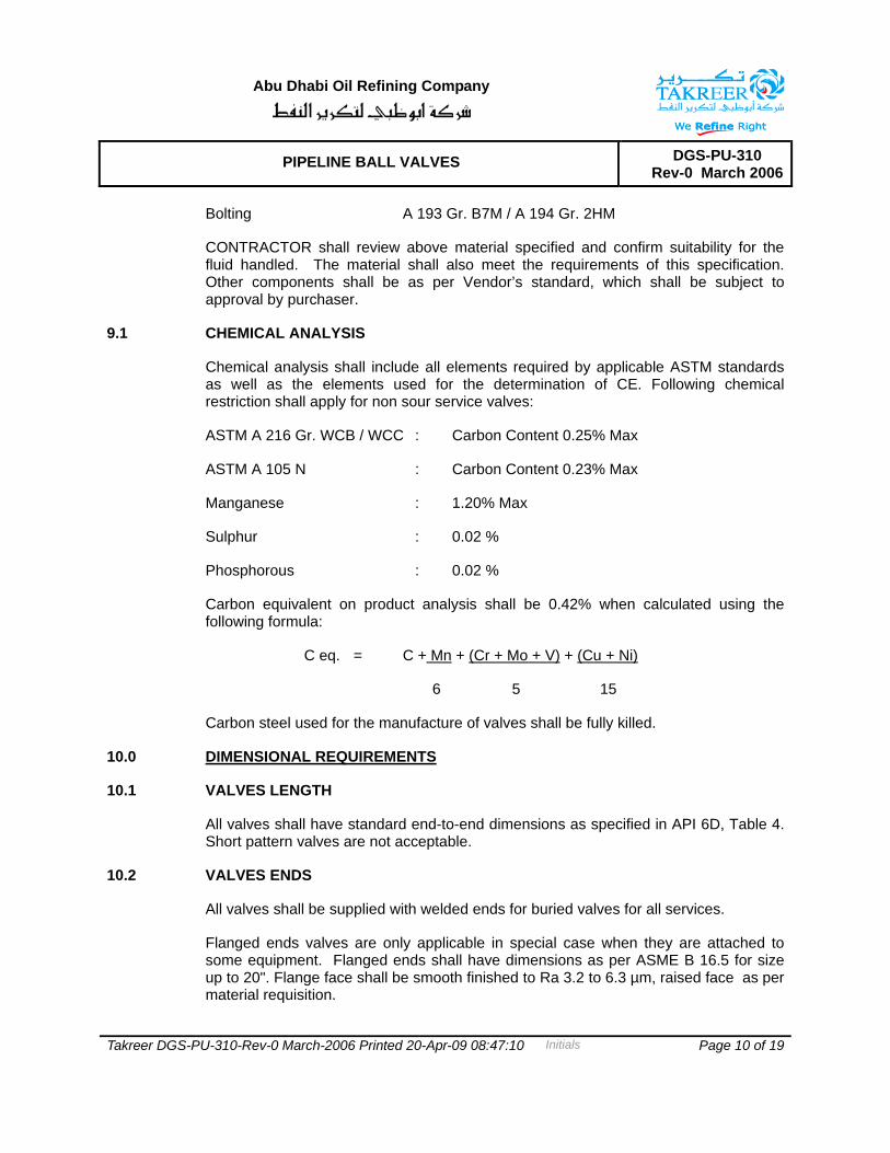
Bolting A 193 Gr. B7M / A 194 Gr. 2HM
CONTRACTOR shall review above material specified and confirm suitability for the fluid handled. The material shall also meet the requirements of this specification. Other components shall be as per Vendor’s standard, which shall be subject to approval by purchaser.
9.1 CHEMICAL ANALYSIS
Chemical analysis shall include all elements required by applicable ASTM standards as well as the elements used for the determination of CE. Following chemical restriction shall apply for non sour service valves:
ASTM A 216 Gr. WCB / WCC : Carbon Content 0.25% Max
ASTM A 105 N : Carbon Content 0.23% Max
Manganese : 1.20% Max
Sulphur : 0.02 %
Phosphorous : 0.02 %
Carbon equivalent on product analysis shall be 0.42% when calculated using the following formula:
C eq. = C + Mn + (Cr + Mo + V) + (Cu + Ni)
6 5 15
Carbon steel used for the manufacture of valves shall be fully killed.
10.0 DIMENSIONAL REQUIREMENTS
10.1 VALVES LENGTH
All valves shall have standard end-to-end dimensions as specified in API 6D, Table 4. Short pattern valves are not acceptable.
10.2 VALVES ENDS
All valves shall be supplied with welded ends for buried valves for all services.
Flanged ends valves are only applicable in special case when they are attached to some equipment. Flanged ends shall have dimensions as per ASME B 16.5 for size up to 20". Flange face shall be smooth finished to Ra 3.2 to 6.3 µm, raised face as per material requisition.
Abu Dhabi Oil Refining Company
PIPELINE BALL VALVES DGS-PU-310 Rev-0 March 2006
Takreer DGS-PU-310-Rev-0 March-2006 Printed 20-Apr-09 08:47:10 Initials Page 11 of 19
Valves up to 4" diameter shall be provided with integral pup pieces (extended body on both sides by minimum 200 mm). Valves above 4" and up to 20" diameter shall be provided with pup piece minimum 400 mm on both sides. For higher sizes, the length of pup shall be minimum half diameter.
Length of pup piece shall be confirmed by the supplier so as to avoid damage to seats during field welding or post weld heat treatment.
Pup piece shall be of the same material as the adjoining line pipe. Vendor shall provide test rings (500 mm long) from pup piece material for field weld procedure qualification.
10.3 BORE
All piggable ball valves, isolation valves for pig signaller and other valves identified in P&IDs as FB shall be furnished as full bore and shall have minimum bore as established in API 6D, Table 1.
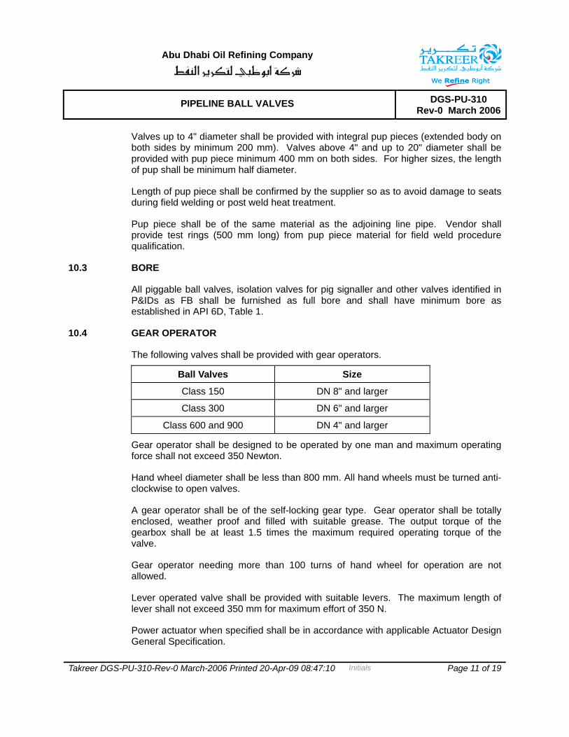
10.4 GEAR OPERATOR
The following valves shall be provided with gear operators.
Ball Valves Size
Class 150 DN 8" and larger
Class 300 DN 6" and larger
Class 600 and 900 DN 4" and larger
Gear operator shall be designed to be operated by one man and maximum operating force shall not exceed 350 Newton.
Hand wheel diameter shall be less than 800 mm. All hand wheels must be turned anti-clockwise to open valves.
A gear operator shall be of the self-locking gear type. Gear operator shall be totally enclosed, weather proof and filled with suitable grease. The output torque of the gearbox shall be at least 1.5 times the maximum required operating torque of the valve.
Gear operator needing more than 100 turns of hand wheel for operation are not allowed.
Lever operated valve shall be provided with suitable levers. The maximum length of lever shall not exceed 350 mm for maximum effort of 350 N.
Power actuator when specified shall be in accordance with applicable Actuator Design General Specification.
Abu Dhabi Oil Refining Company
PIPELINE BALL VALVES DGS-PU-310 Rev-0 March 2006
Takreer DGS-PU-310-Rev-0 March-2006 Printed 20-Apr-09 08:47:10 Initials Page 12 of 19
Valve design shall be such that damage due to malfunctioning of the operator or its controls will only occur in the operator gear train or power cylinder and that damaged parts can be replaced without the valve cover being removed.
11.0 TESTING
11.1 HYDROSTATIC TESTING
All valves flanged and butt-welding ends shall be hydraulically tested at the test pressures required by API-6D. Welded ends valves shall be tested along with pup pieces.
The test medium for both shell and seat tests shall be water. The minimum duration of the shell test and the seat test shall be no less than that specified in API 6D. During the seat test, the test pressure shall be raised to 75 PSI and stopped long enough to ascertain whether the seat is leaking, then the pressure shall be increased to the pressures listed in the Code. The test fluid for hydrostatic testing shall be an emulsion of water with soluble oil. The chloride content of the test fluid shall not exceed 50 ppm.
11.2 COMPRESSED AIR TEST
Supplementary air seat test as per API 6D shall be carried out. A bubble tight seal is required without use of sealant. No leakage is allowed.
11.3 NON-DESTRUCTIVE EXAMINATION (NDE) FOR VALVE CASTINGS
Class 1 NDE shall be 100 percent visual examination of all castings. In addition, either 100 percent dye penetrant examination or 100 percent magnetic particle inspection (dependent on material type) and radiographic examination of all critical areas as defined in Section 8.3 of ASME B 16.34 for all castings.
Class 2 NDE shall be 100 percent visual examination of all castings. In addition, either 100 percent dye penetrant examination or 100 percent magnetic particle inspection (dependent on material type) and Radiographic Examination of all critical areas only of 10 percent of the castings of each size and stock code number (minimum one). In case of any failure, further examination shall be carried on all casting.
Class 3 NDE shall be 100 percent visual examination of all castings other examination as per Supplier standard procedure, and to be submitted with bid.
NDE procedures and Acceptance Standards shall be:
Radiography ASME B 16.34, Annex B
Dye Penetrant Procedure ASTM E 165
Examination Acceptance ASME B 16.34, Annex D Section D, 2.1
Abu Dhabi Oil Refining Company
PIPELINE BALL VALVES DGS-PU-310 Rev-0 March 2006
Takreer DGS-PU-310-Rev-0 March-2006 Printed 20-Apr-09 08:47:10 Initials Page 13 of 19
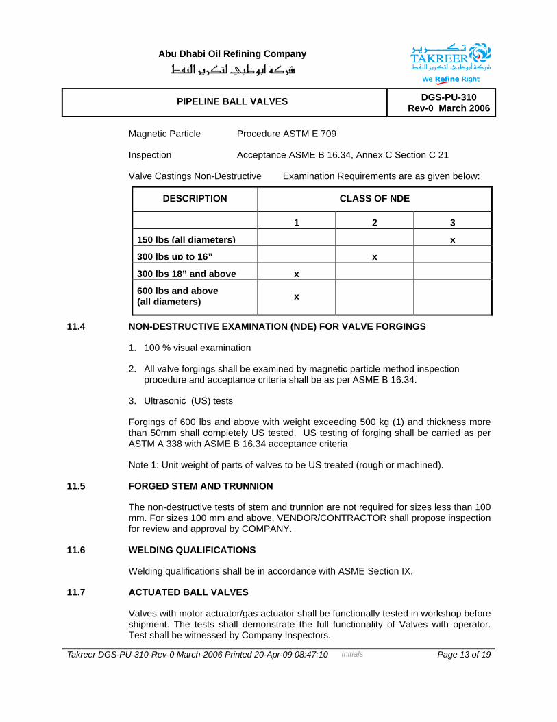
Magnetic Particle Procedure ASTM E 709
Inspection Acceptance ASME B 16.34, Annex C Section C 21
Valve Castings Non-Destructive Examination Requirements are as given below:
DESCRIPTION CLASS OF NDE
1 2 3
150 lbs (all diameters) x
300 lbs up to 16” x
300 lbs 18” and above x
600 lbs and above (all diameters) x
11.4 NON-DESTRUCTIVE EXAMINATION (NDE) FOR VALVE FORGINGS
1. 100 % visual examination
2. All valve forgings shall be examined by magnetic particle method inspection procedure and acceptance criteria shall be as per ASME B 16.34.
3. Ultrasonic (US) tests
Forgings of 600 lbs and above with weight exceeding 500 kg (1) and thickness more than 50mm shall completely US tested. US testing of forging shall be carried as per ASTM A 338 with ASME B 16.34 acceptance criteria
Note 1: Unit weight of parts of valves to be US treated (rough or machined).
11.5 FORGED STEM AND TRUNNION
The non-destructive tests of stem and trunnion are not required for sizes less than 100 mm. For sizes 100 mm and above, VENDOR/CONTRACTOR shall propose inspection for review and approval by COMPANY.
11.6 WELDING QUALIFICATIONS
Welding qualifications shall be in accordance with ASME Section IX.
11.7 ACTUATED BALL VALVES
Valves with motor actuator/gas actuator shall be functionally tested in workshop before shipment. The tests shall demonstrate the full functionality of Valves with operator. Test shall be witnessed by Company Inspectors.
Abu Dhabi Oil Refining Company
PIPELINE BALL VALVES DGS-PU-310 Rev-0 March 2006
Takreer DGS-PU-310-Rev-0 March-2006 Printed 20-Apr-09 08:47:10 Initials Page 14 of 19
11.8 NON DESTRUCTIVE EXAMINATION OF WELDS
Full inspection by radiography shall be carried out on all welds of pressure containing parts. Acceptance criteria shall be as per ASME B 31.4 and API 1104. Welds, which in Purchaser’s opinion cannot be inspected by radiographic methods shall be checked by ultrasonic or magnetic particle methods and acceptance criteria shall be as per ASME Section VIII Div. 1, Appendix 12 and appendix 6 respectively.
11.9 NON DESTRUCTIVE EXAMINATION FOR BUTT ENDS
a. All finished wrought weld ends shall be 100% ultrasonically tested for lamination type of defects for a distance of 50 mm from the end. Laminations shall not be acceptable.
b. Weld ends of all cast valves shall be 100% radiographically examined and acceptance criteria shall be as per ASME B 16.34.
c. After final machining all bevel surfaces shall be inspected by magnetic particle methods. All defects longer than 6,35 mm are rejected, as are defects between 1,59 mm and 6,35 mm that are separated by a distance of less than 50 times their greatest length. Rejectable defects must be removed. Weld repair of bevel surface is not permitted.
11.10 FIELD TESTS AT SITE
The seats of all main line full bore valves, ROVs on branches, hot tap valves, launches/receiver main isolation valves and all tight shut-off valves (TSO) indicated on P&ID shall be field tested before installation. Testing shall be done as per API 6D both for hydrostatic & compressed air testing.
12.0 INSPECTION
The responsibility for inspection and testing rests with the CONTRACTOR. However, the COMPANY reserves the right to inspect the equipment at any time during the fabrication to ensure that materials and workmanship are in accordance with specification and reference drawings.
Chemical composition and mechanical properties shall be checked as per relevant material standards and this specification for each heat of steel used.
Non-destructive examination of individual valve material and components of, but not limited, to castings forging, plate and assembly welds shall be carried out by the Manufacturer.
All valve components shall be tested in accordance with their applicable ASTM, ASME, MSS, or other referenced Code or Standard.
All valves shall be visually inspected.

Abu Dhabi Oil Refining Company
PIPELINE BALL VALVES DGS-PU-310 Rev-0 March 2006
Takreer DGS-PU-310-Rev-0 March-2006 Printed 20-Apr-09 08:47:10 Initials Page 15 of 19
Dimensional check shall be carried out as per the approved drawing.
The approval of any work by the COMPANY and/or release of the unit for shipment shall in no way release CONTRACTOR of responsibility for carrying out all provisions of these specifications.
CONTRACTOR shall notify the COMPANY of their intentions to carry out factory tests at least two weeks prior to the commencement of such tests.
CONTRACTOR shall notify the COMPANY one week prior to start of assembly of the valve(s) so the COMPANY can exercise their option to witness the assembly.
13.0 PAINTING AND COATING
All Carbon Steel surfaces shall be prepared and painted in accordance with DGS-MX-001 Design General Specification for painting and its project specific addendum. Valves intended for use in buried installation shall be coated in accordance with DGS-MY-001. The requirement for painting and coating shall be specified in the purchase order.
14.0 MARKING
CONTRACTOR shall mark all valves in accordance with MSS SP-25 Standard Marking System for Valves, Fittings, Flanges and Unions. In addition to standard nameplate required by relevant valve standard, additional stainless steel tags shall be attached through riveting or screwing to/into bonnet flange. 1.5mm diameter is the minimum rivet size. This tag shall be separate from any nameplate affixed to the valve, and with the following markings:
P.O. Number
Equipment Item number
Serial number
Manufacturer
15.0 TRACEABILITY
Materials and Equipment shall be traceable against Purchase Order Number, Purchase Order Item Number, and TAG Number when applicable.
The certification to cover Components, Raw Materials and Parts shall be fully identifiable and traceable against Part Number, Tag Number, Purchase Order Item nos., and Purchase Order Number.
For quality assurance requirements and inspection requirements, refer to the purchase order and its referenced documents.
Abu Dhabi Oil Refining Company
PIPELINE BALL VALVES DGS-PU-310 Rev-0 March 2006
Takreer DGS-PU-310-Rev-0 March-2006 Printed 20-Apr-09 08:47:10 Initials Page 16 of 19
16.0 PREPARATION FOR SHIPMENT
Preparation for shipment shall be in accordance with CONTRACTOR standards for shipment approved by the COMPANY as noted herein.
CONTRACTOR shall be responsible for the adequate preparation of material and application for shipment, and for providing equipment at the destination in ex-works conditions when handled by commercial carriers. Flanges to be protected with 1/4” (6.35 mm) plywood covers and weld ends with bevel protectors. Welded ends shall be blanked off suitably with caps during transportation and while storage at site to avoid ingress of foreign particles etc.
Impression shall be stamped with the following:
P.O. Number
Manufacturer
Equipment Item Number
Description
Serial Number
17.0 VENDOR DATA REQUIREMENTS LIST (VDRL)
The CONTRACTOR/VENDOR shall submit certification and inspection documents to the COMPANY’s representative as specified in the purchase order. Mutual agreement on scheduled submittal of drawings and engineering data shall be an integral part of any formal Purchase Order.
All documents, drawing text and dimensions shall be expressed in English language and shall be in the metric system.
Comments made by CONTRACTOR on drawing submittal shall not relieve VENDOR or SUBVENDORS of any responsibility in meeting the requirements of the specifications. Such comments shall not be construed as permission to deviate from requirements of the Purchase Order unless specific and mutual agreement is reached and confirmed in writing.
Each drawing shall be provided with a title block in the bottom right-hand corner incorporating the following information:
• Official trade name of the VENDOR.
• VENDOR’S drawing number.

Abu Dhabi Oil Refining Company
PIPELINE BALL VALVES DGS-PU-310 Rev-0 March 2006
Takreer DGS-PU-310-Rev-0 March-2006 Printed 20-Apr-09 08:47:10 Initials Page 17 of 19
• Drawing title giving the description of contents whereby the drawing can be identified.
• A symbol or letter indicating the latest issue or revision.
• PO number and item tag numbers.
Revisions to drawing shall be identified with symbols adjacent to the alterations, a brief description in tabular form of each revision shall be given, and if applicable, the authority and date of the revision shall be listed. The term "Latest Revision" shall not be used.
The following documents, procedures, reports and records shall be submitted as a minimum:
• Vendors documentation/literature
• Valve dimensions, dimensional drawings
• Design Calculations (valve pups)
• Production Schedule
• Manufacturing Procedure
• Heat Treatment Procedure and Marking Records
• Marking Procedure
• Valve layouts and details
• Verification certificate per API 6FA for fire safe design
• Installation, Operation and Maintenance Manual
• Valve assembly drawings with complete parts list
• General Arrangement Drawings
• Schematic Drawings
• Two years recommended spare parts list
• Special Tools
• Commissioning Spare Parts

Abu Dhabi Oil Refining Company
PIPELINE BALL VALVES DGS-PU-310 Rev-0 March 2006
Takreer DGS-PU-310-Rev-0 March-2006 Printed 20-Apr-09 08:47:10 Initials Page 18 of 19
• Quality, Inspection & Test Plan (to be submitted for COMPANY approval, prior to start of manufacturing)
• Mechanical Test Reports
• Hydrostatic Test Reports
• NDT Test Reports
• Valve welding procedure including welding of pup piece
• Weld Procedure and Welder Qualification Certificates
• Inspection and Test Procedures and Records Material Certificates according to ISO 10474
• Rating 150 # 3.1.B
• Rating 300# & above 3.1 C
• Certified Chemical Analysis
• Certificate of Conformance and Dimensional Check Report
• Final Inspection Report
• Verification Certificates for Standard Compliance
• All concession requests

Abu Dhabi Oil Refining Company
PIPELINE BALL VALVES DGS-PU-310 Rev-0 March 2006
Takreer DGS-PU-310-Rev-0 March-2006 Printed 20-Apr-09 08:47:10 Initials Page 19 of 19
ADDENDUM SHEET
All revisions to this DGS subsequent to the issue of Rev Zero shall be recorded in this addendum sheet and shall be incorporated into the DGS in the next revision.
Date Proposed Revision Remarks