DGS BOOSTER SYSTEM - felcon · Booster compressor The central element of the system is a...
8
CH-3185 Schmitten Tel. +41 26 497 55 66 Mail: [email protected] DGS BOOSTER SYSTEM felcon ag ingenieurbüro anlagenbau
Transcript of DGS BOOSTER SYSTEM - felcon · Booster compressor The central element of the system is a...

CH-3185 Schmitten Tel. +41 26 497 55 66 Mail: [email protected]
DGS BOOSTER SYSTEM
felcon ag
ingenieurbüro anlagenbau

The appearance of liquids or even hydrates in the Dry Gas Seals (DGS) may badly affect their trouble-free operation. If the sealing faces of the DGS are contaminated during pressurized standstill conditions they potentially suffer damage during compressor start-up. The booster rack provides clean, superheated seal gas to the DGS and hence prevents the formation of liquids and hydrates during times of pressurized standstill of the machine train.
Challenge When compressors shut down and the gas in the compression loop is not blown down, the gas pressure equalises at a higher pressure than compressor suction pressure, known as settle-out pressure. Following a shutdown the gas in the compression loop cools down and may reach ambient temperature after a while. If the dew points of the gas components at settle-out conditions are higher than the gas temperature (this often is the case for gases with heavy hydrocarbon components), liquids or even hydrates may be formed. The formation of liquids and hydrates is not a problem for the compressor itself but can
badly affect trouble-free operation of Dry Gas Seals (DGS). If the sealing faces of the DGS are contaminated with hydrates they may suffer damage during compressor start-up. This may cause seal failures and, as a consequence, an increase in unplanned downtime and repair costs. In the past a common practice to reduce the problem of contamination was to epressurize the compression loop shortly after a shutdown. However, today’s environmental
legislation and operators policies call for a reduction of process gas releases to flare or environment. .
CH-3185 Schmitten | +41 26 497 55 66 | [email protected]

Solution The booster rack provides clean, superheated seal gas to the DGS and hence prevents the formation of liquids and hydrates during pressurized standstill periods. In principle, an instrument air driven doubleacting piston compressor feeds the gas to the compressor in a closed loop system. A gas heater maintains the required seal gas temperature above the dew points. To avoid liquid and hydrate formation when the booster rack is not in operation, all seal gas pipework on the unit and the interconnecting piping have to be heat traced and lagged.
Advantages The compact booster rack is a very reliable and cost effective solution if there is a danger that condensation of seal gas may lead to deterioration of the seal lifetime. The advantages can be summarised as follows:
extended lifetime of DGS defined seal gas conditions and hence compressor conditions increased plant reliability simple system with well proven components
ready to use and easy to fit into an existing system well proven system used in different plants worldwide only minor changes to control system necessary potentially reduced pollution tax costs flexible design to adapt to customer specification cost effective system reduced maintenance costs of DGS
DGS booster rack The DGS booster rack is an independent system which mainly consists of the booster compressor, seal gas heater, seal gas filter and all necessary instruments and valves for control and maintenance. It can easily be linked to existing DGS systems without major modification.
CH-3185 Schmitten | +41 26 497 55 66 | [email protected]

Booster compressor The central element of the system is a double-acting piston-type booster driven by instrument air. The booster compresses the gas and feeds it via a damping bottle and the heater to the compressor. The piston in the drive cylinder is attached to the piston in the boost cylinder. As the drive piston reciprocates, it compresses the gas in the boost cylinder. The booster is equipped with a distance piece designed to ensure that the gas in the boost cylinder is isolated from the air in the drive cylinder. This design allows very simple drive, operation and control of the booster rack. A simple on/off solenoid valve starts and stops the booster. Alternatively, nitrogen could also be used as driving medium.
Gas filter The well proven single coalescing filter in he seal gas supply line protects the booster from abrasive particles and removes any liquid which may be present. If specified a double filter can be installed.
Gas heater The compact heater rises the temperature of the process gas well above a level where
condensation may occur. Instrumentation The booster rack contains all instruments required to operate and monitor the booster system. The following instruments are fitted for the basic system configuration:
Gas system:
differential pressure for inlet gas filter indication of heater temperature safety switch for heater gas temperature for heater control differential pressure seal gas inlet/outlet Drive air system: pressure reducing valve pressure indication
start/stop solenoid valve
CH-3185 Schmitten | +41 26 497 55 66 | [email protected]
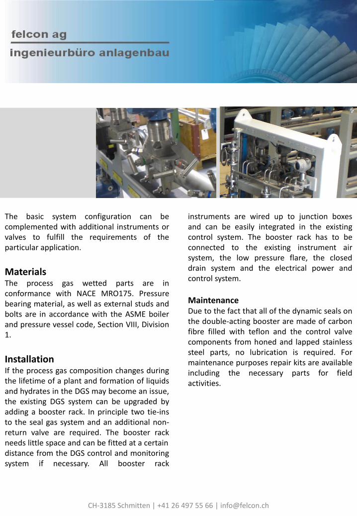
The basic system configuration can be complemented with additional instruments or valves to fulfill the requirements of the particular application.
Materials The process gas wetted parts are in conformance with NACE MRO175. Pressure bearing material, as well as external studs and bolts are in accordance with the ASME boiler and pressure vessel code, Section VIII, Division 1.
Installation If the process gas composition changes during the lifetime of a plant and formation of liquids and hydrates in the DGS may become an issue, the existing DGS system can be upgraded by adding a booster rack. In principle two tie-ins to the seal gas system and an additional non-return valve are required. The booster rack needs little space and can be fitted at a certain distance from the DGS control and monitoring system if necessary. All booster rack
instruments are wired up to junction boxes and can be easily integrated in the existing control system. The booster rack has to be connected to the existing instrument air system, the low pressure flare, the closed drain system and the electrical power and control system.
Maintenance Due to the fact that all of the dynamic seals on the double-acting booster are made of carbon fibre filled with teflon and the control valve components from honed and lapped stainless steel parts, no lubrication is required. For maintenance purposes repair kits are available including the necessary parts for field activities.
CH-3185 Schmitten | +41 26 497 55 66 | [email protected]

Three pressure classes of booster racks are available
DGS Booster System
Booster model type Low pressure Medium pressure High pressure
Max. gas boost pressure [bar] 113 200 351
Booster displacement [l/cycle ] 0.906 0.623 0.623
Gas temperature range [°C]
-26 to 204
Heater rating According to gas composition
typical 10kW
CH-3185 Schmitten | +41 26 497 55 66 | [email protected]

Simplified P&I diagram of a DGS shaft sealing system (tandem seal nitrogen buffered) incl. DGS booster rack
CH-3185 Schmitten | +41 26 497 55 66 | [email protected]