DG 250 Communications Engineering Design Criteria and ...
133
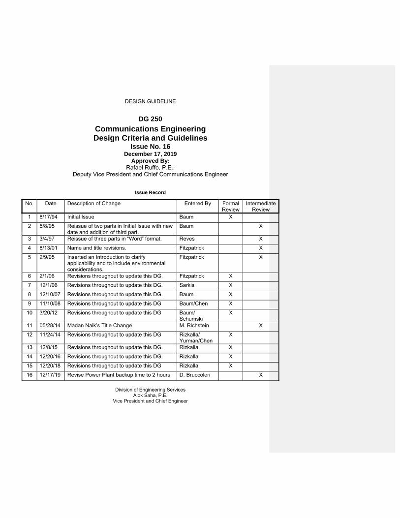
DESIGN GUIDELINE DG 250 Communications Engineering Design Criteria and Guidelines Issue No. 16 December 17, 2019 Approved By: Rafael Ruffo, P.E., Deputy Vice President and Chief Communications Engineer Issue Record No. Date Description of Change Entered By Formal Review Intermediate Review 1 8/17/94 Initial Issue Baum X 2 5/8/95 Reissue of two parts in Initial Issue with new date and addition of third part. Baum X 3 3/4/97 Reissue of three parts in “Word” format. Reves X 4 8/13/01 Name and title revisions. Fitzpatrick X 5 2/9/05 Inserted an Introduction to clarify applicability and to include environmental considerations. Fitzpatrick X 6 2/1/06 Revisions throughout to update this DG. Fitzpatrick X 7 12/1/06 Revisions throughout to update this DG. Sarkis X 8 12/10/07 Revisions throughout to update this DG. Baum X 9 11/10/08 Revisions throughout to update this DG Baum/Chen X 10 3/20/12 Revisions throughout to update this DG Baum/ Schumski X 11 05/28/14 Madan Naik’s Title Change M. Richstein X 12 11/24/14 Revisions throughout to update this DG Rizkalla/ Yurman/Chen X 13 12/8/15 Revisions throughout to update this DG. Rizkalla X 14 12/20/16 Revisions throughout to update this DG. Rizkalla X 15 12/20/18 Revisions throughout to update this DG Rizkalla X 16 12/17/19 Revise Power Plant backup time to 2 hours D. Bruccoleri X Division of Engineering Services Alok Saha, P.E. Vice President and Chief Engineer
Transcript of DG 250 Communications Engineering Design Criteria and ...
DESIGN GUIDELINE
DG 250
Communications Engineering Design Criteria and Guidelines
Issue No. 16 December 17, 2019
Approved By: Rafael Ruffo, P.E.,
Deputy Vice President and Chief Communications Engineer
Issue Record
No. Date Description of Change Entered By Formal Review
Intermediate Review
1 8/17/94 Initial Issue Baum X
2 5/8/95 Reissue of two parts in Initial Issue with new date and addition of third part.
Baum X
3 3/4/97 Reissue of three parts in “Word” format. Reves X
4 8/13/01 Name and title revisions. Fitzpatrick X
5 2/9/05 Inserted an Introduction to clarify applicability and to include environmental considerations.
Fitzpatrick X
6 2/1/06 Revisions throughout to update this DG. Fitzpatrick X
7 12/1/06 Revisions throughout to update this DG. Sarkis X
8 12/10/07 Revisions throughout to update this DG. Baum X
9 11/10/08 Revisions throughout to update this DG Baum/Chen X
10 3/20/12 Revisions throughout to update this DG Baum/ Schumski
X
11 05/28/14 Madan Naik’s Title Change M. Richstein X
12 11/24/14 Revisions throughout to update this DG Rizkalla/ Yurman/Chen
X
13 12/8/15 Revisions throughout to update this DG. Rizkalla X
14 12/20/16 Revisions throughout to update this DG. Rizkalla X
15 12/20/18 Revisions throughout to update this DG Rizkalla X
16 12/17/19 Revise Power Plant backup time to 2 hours D. Bruccoleri X
Division of Engineering Services
Alok Saha, P.E. Vice President and Chief Engineer

Communications Engineering
Design Criteria and Guidelines
Issue 16
DG250
Page 2
TABLE OF CONTENTS
INTRODUCTION Page
I General 5
II Environmental Considerations 5
III Design Considerations for Future Operational Changes/Needs 6
IV General Design Provisions 6
V Training and Related Items Required for Contract Completion 6
VI Power for Communications Equipment. 6
VII Design Considerations for Flood Resiliency 7
VIII Seismic Design for Nonstructural Components 7
IX Design Considerations for Outside Projects 8
X References 9
XI Terms and Definitions 9
PART ONE WIRED SYSTEMS AND MISCELLANEOUS EQUIPMENT 13
I Introduction 13
II Design Requirements – General 13
III Design Requirements - Specific Systems 14
A Telephone Cabling 14
B Emergency Alarm (EA) System 18
C Telephone Systems/Sets 23
D Passenger Station Public Address System 24
E Security/Access Control and Intrusion Detection Alarm System 26
F CCTV (Closed Circuit Television) System 32
G Fire Detection/Alarm System 37
H Speakerphone Systems 59
I Train Dispatching System and No.6 Emergency Line 60
J Various Communications Equipment for Fare Booths 63
K Integrated Telephone/Paging System 63
L Sound Powered Telephone Systems 64
M Miscellaneous Equipment and Systems: 65
I. Clocks, Synchronization and Related Items II. Fire Extinguishers

Communications Engineering
Design Criteria and Guidelines
Issue 16
DG250
Page 3
III. Intercom Systems IV. Pump Rooms V. Commercial Dynamic Signage VI. LCD Based Customer Information Displays VII. Remote Eyewash Alarm
N Data Cabling and Equipment 69
O Communications Room Considerations 69
P Power Plant Guidelines 71 1 New Power Plant 72 2 Augmenting Power Plant 73 3 Power Plant Installations 73 4. Power Plant Testing 73 5. Powering PSLAN Access Nodes from Power Plant 73
Q Additional Cabling Criteria 73
R Sample Calculations 74
1 Messenger Bracket Spacing 2 Messenger Sag 3 Raceway Fill
S Communication Design Contract Requirements 77
PART TWO WIRELESS COMMUNICATIONS AND SYSTEMS 80
I Introduction 80
II Design Requirements – General 80
III Design Requirements and Guidelines - Specific Systems 83
A Subway UHF/VHF Wireless Voice Communications 83
B Video-Data Wireless Systems 85
C Mixed Voice and Data Wireless Communication Systems 93
IV Contract Category/Specific System Matrix 104
PART THREE DESIGN CHECKLISTS FOR CONTRACT DRAWING TYPES 105
I Telephone Cable/Fiber Optic Nodes 105
II Emergency Alarm Systems 108
III Telephone Systems/Sets 111
IV Public Address/Customer Information Sign System 114
V Security Alarm System 117

Communications Engineering
Design Criteria and Guidelines
Issue 16
DG250
Page 4
VI CCTV/ PID System 120
VII Fire Detection/Alarm Systems 123
VIII HP& Speakerphone Systems 126
IX Wireless 129
X Communications Room System/Equipment Space 132
XI Appendix A 133
Communications Engineering
Design Criteria and Guidelines
Issue 16
DG250
Page 5
INTRODUCTION
I General This document provides general design guidelines for systems and equipment
under the purview of Communications Engineering. Some of these systems use the Authority’s communications network for voice/data transmission to remote locations and may be considered as network applications. Other equipment and systems (e.g., fare booth intercom, sound powered telephone) are strictly local in nature.
Guidelines for Communications Engineering also appear in other design
guidelines. For SCADA design, Optical Networking design at any location, or work at passenger stations, bus depots, car maintenance facilities and other locations, see the applicable design guideline(s) from the most current list of design guidelines, available on the TENS web site.
The current SONET/ATM network is used to carry most traffic generated by
the applications (as described in this guideline) to their intended head-end location (such as RCC). Details of the SONET/ATM network and guidelines for network design can be found in DG 259. New station networks are to be designed around SONET/Metro Ethernet.
II Environmental Considerations
The following environmental considerations apply to all Communications
Engineering designs: 1. Equipment such as video monitors, and other equipment as applicable,
shall be Energy Star compliant. Power consumption (energy efficiency) shall be a consideration when selecting equipment.
2. Activities such as, but not limited to, cable splicing and soldering of lead
containing materials shall be performed in accordance with contract Specification Section 12L - Removal/Disturbance of Lead Containing Materials.
3. Materials that are known to be hazardous (e.g., Asbestos) shall not be
used in any manner or in any compound (such as duct sealant compound).
4. Deploy measures as required (filters, positive pressure) to minimize
steel dust infiltration into Communications rooms.
Communications Engineering
Design Criteria and Guidelines
Issue 16
DG250
Page 6
5. For Communications cabinet cooling solution refer to specification section Heating, Ventilation, and Air Conditioning 15H. If remote monitoring for the cabinet cooling and ventilating solution is required then refer to specification section Equipping Communications Rooms for Network Applications 19CR.
III Design Considerations for Future Operational Changes/Needs
Major operational changes that have begun or are scheduled to be
implemented in the near future shall be identified in the Scope of Work and taken into account in current designs.
IV General Design provisions
All new equipment/systems shall be in full compliance with the Authority current design standards. See reference section IX. New equipment/systems that are expansions of existing installations shall be seamlessly integrated with the existing system including transmitting and receiving controls, indications, data and programming instructions from the existing head end equipment.
Updates, additions and modifications to RCC existing head-ends shall be
mirrored at 130 Livingston St. (RCC’s Backup location).
V Training and Related Items Required for Contract Completion. For each type of work to be included in the contract, a decision must be made
regarding a need for training. Coordinate training requirements with equipment/systems users and maintainers. In general, maintenance training - for personnel who will be responsible to repair and maintain the equipment - is required for all new systems. For systems requiring use of a computer workstation, operator training and system administrator training may be required. For less complicated equipment, a simple demonstration of the equipment operation may be sufficient. The master contract specifications also provide requirements for record drawings and manuals. All contracts that contain Communications work shall include approved samples of AS-BUILT drawings and an AS-BUILT drawing title block in the bid package.
VI Power for Communications Equipment.
In many cases, Communications equipment and systems are powered from a
large UPS (power plant) located in the nearest Communications Room. For power plant refer to Specification Section 19CR.
For equipment powered locally instead of from the Communications Room,
coordinate with Electrical Design to provide needed feeds where separate circuits for

Communications Engineering
Design Criteria and Guidelines
Issue 16
DG250
Page 7
each system or piece of equipment are required. For locally powered equipment that will require backup power in the event of a power failure, a local UPS must be supplied to allow that equipment to be properly shut down or be maintained in operation for a specified duration (see individual systems for required durations).
VII Design Considerations for Flood Resiliency Designer shall follow additional resiliency requirements for projects categorized under
Flood Resiliency as per Flood Resiliency Design Guideline DG 312:
1. Cabinets, enclosures and pull-boxes shall be rated for NEMA-4X 2. Conduits shall be rated for wet environments 3. All room penetrations shall be sealed with water-tight sleeves 4. Conduits and pull boxes shall be installed as high as possible 5. All conduits shall be sealed to handle up to 22 ft. water-head pressure 6. Mounting should be above flood level; if this is not possible, clearly identify this
and ensure all components of design are rated for water immersion 7. Cables installed on messengers inside tunnels shall be mounted as high as
possible as permitted by field conditions and in accordance with LLLE (Limiting Line of Line Equipment) requirements.
8. Equipment shall not be placed within or through vent bays or attached to vent gratings. Vent gratings must be cleared of all obstructions in order to allow installation of Mechanical Closure Devices and Deployable Vent Covers. Waivers need to be requested from MOW Chief Engineering Officer for any design where this is unavoidable.
VIII Seismic Design for Nonstructural Components
1. Factors that govern the incorporation of seismic design requirements for communications systems are summarized as follows:
a) Structural Engineering’s determination of the Seismic Design Category per the International Building Code and New York State Uniform Code Supplement approved for the project.
b) Design Manager’s determination of the Occupancy Category of the
facility/structure in coordination with the user department /facility’s owner and NYCT Code Compliance group.
c) Design Manager’s determination of the Importance Factor of communications
system components in coordination with the user department /facility’s owner as per the International Building Code and New York State Uniform Code Supplement approved for the project and based on:
1) Occupancy Category of the facility/structure. 2) The communications system components that are required to function for life-safety purposes after an earthquake.
Communications Engineering
Design Criteria and Guidelines
Issue 16
DG250
Page 8
3) The communications system components that are needed for continued operation of the facility after an earthquake.
2. If determined by the Design Manager that seismic design requirements for communications system components is required, coordinate with the Design Manager to have the Seismic Design for communications system components prepared by either:
a) The contractor, during construction phase, provided that communications
engineering design team prepares and includes into contract design documents performance requirements that require the contractor to be fully responsible for the seismic design and calculations, seismic hardware specifications and the seismic installation details for conduit and enclosures.
OR
b) NYCT Structural Engineering in-House design in coordination with all involved
design disciplines.
3. Seismic design submittals during construction phase, per item 2.a/2.b above will be reviewed by NYCT Structural Engineering in-House design team.
IX. Design Considerations for Outside Projects Outside projects are defined as work in or about NYCT transit facilities performed by a
private interest, or other governmental agency. All coordination is performed by Structural Design Outside Projects Group. The designers of record and associated contractors are not under the direct supervision of NYCT, but NYCT is involved in the approval of drawings and construction in accordance with the Legal Agreement of the project and the following:
a) Systems that will remain under the ownership of a private interest, or other
governmental authority, are not required to follow NYCT Communications Engineering standards. An exception to this is an Elevator/Escalator monitoring system (i.e- Liftnet). The Liftnet shall not connect directly to the NYCT data network but rather shall connect to the NYCT Liftnet Head End System via Verizon or other third party connection means, in coordination with MTA IT.
b) Systems that are constructed by outside projects for NYCT ownership shall
follow NYCT Communications Engineering standards.
c) Systems that are constructed by others for NYCT for ownership but proposed to be maintained by a private interest or other governmental agency, shall follow NYCT Communications Engineering standards only if maintenance plans and procedures are first approved by NYCT DoS and Legal Department.
Communications Engineering
Design Criteria and Guidelines
Issue 16
DG250
Page 9
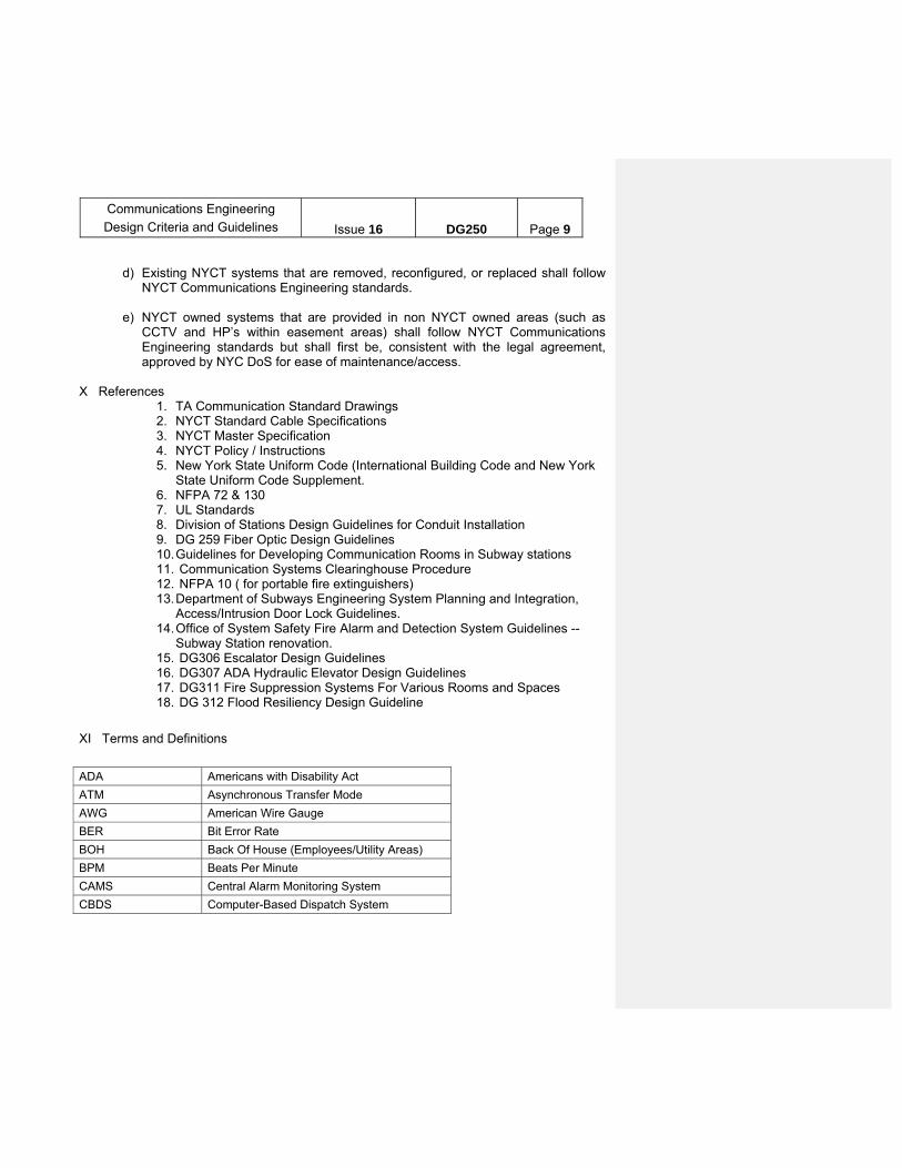
d) Existing NYCT systems that are removed, reconfigured, or replaced shall follow
NYCT Communications Engineering standards.
e) NYCT owned systems that are provided in non NYCT owned areas (such as CCTV and HP’s within easement areas) shall follow NYCT Communications Engineering standards but shall first be, consistent with the legal agreement, approved by NYC DoS for ease of maintenance/access.
X References
1. TA Communication Standard Drawings 2. NYCT Standard Cable Specifications 3. NYCT Master Specification 4. NYCT Policy / Instructions 5. New York State Uniform Code (International Building Code and New York
State Uniform Code Supplement. 6. NFPA 72 & 130 7. UL Standards 8. Division of Stations Design Guidelines for Conduit Installation 9. DG 259 Fiber Optic Design Guidelines 10. Guidelines for Developing Communication Rooms in Subway stations 11. Communication Systems Clearinghouse Procedure 12. NFPA 10 ( for portable fire extinguishers) 13. Department of Subways Engineering System Planning and Integration,
Access/Intrusion Door Lock Guidelines. 14. Office of System Safety Fire Alarm and Detection System Guidelines --
Subway Station renovation. 15. DG306 Escalator Design Guidelines 16. DG307 ADA Hydraulic Elevator Design Guidelines 17. DG311 Fire Suppression Systems For Various Rooms and Spaces 18. DG 312 Flood Resiliency Design Guideline
XI Terms and Definitions
ADA Americans with Disability Act
ATM Asynchronous Transfer Mode
AWG American Wire Gauge
BER Bit Error Rate
BOH Back Of House (Employees/Utility Areas)
BPM Beats Per Minute
CAMS Central Alarm Monitoring System
CBDS Computer-Based Dispatch System
Communications Engineering
Design Criteria and Guidelines
Issue 16
DG250
Page 10
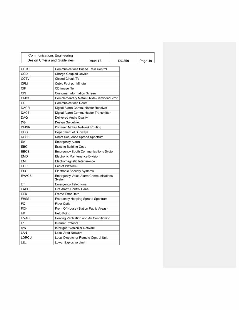
CBTC Communications Based Train Control
CCD Charge-Coupled Device
CCTV Closed Circuit TV
CFM Cubic Feet per Minute
CIF CD image file
CIS Customer Information Screen
CMOS Complementary Metal- Oxide-Semiconductor
CR Communications Room
DACR Digital Alarm Communicator Receiver
DACT Digital Alarm Communicator Transmitter
DAQ Delivered Audio Quality
DG Design Guideline
DMNR Dynamic Mobile Network Routing
DOS Department of Subways
DSSS Direct Sequence Spread Spectrum
EA Emergency Alarm
EBC Existing Building Code
EBCS Emergency Booth Communications System
EMD Electronic Maintenance Division
EMI Electromagnetic Interference
EOP End of Platform
ESS Electronic Security Systems
EVACS Emergency Voice Alarm Communications System
ET Emergency Telephone
FACP Fire Alarm Control Panel
FER Frame Error Rate
FHSS Frequency Hopping Spread Spectrum
FO Fiber Optic
FOH Front Of House (Station Public Areas)
HP Help Point
HVAC Heating Ventilation and Air Conditioning
IP Internet Protocol
IVN Intelligent Vehicular Network
LAN Local Area Network
LDRCU Local Dispatcher Remote Control Unit
LEL Lower Explosive Limit

Communications Engineering
Design Criteria and Guidelines
Issue 16
DG250
Page 11
MCSD Mass Call and Speed Dial
MDF Main Density Fiberboard
MMF Multi-Mode Fiber
MOW Maintenance of Way
MPLS Multiprotocol Label Switching
NAC Notification Appliance Circuit
NEMA National Electrical Manufacturer’s Association
NFPA National Fire Protection Association
NYS New York State
NYC New York City
OSS Office of System Safety
OTG On-The-Go
PA Public Address
PA/CIS Public Address/Customer Information Screen
PBX Private Branch Exchange
PID Passenger Identification
PoE Power over Ethernet
P.P.T Portable Panic Transmitter
PSIM Physical Security -Integration Management
PS-LAN Passenger Station-Local Area Network
PTZ Pan, Tilt, Zoom
RCC Rail Control Center
R.P.S Remote Processing Station
RTO Rapid Transit Operations
SACNS SONET ATM Communications Network System
SAID Service Advisory Information Display
SCADA Supervisory Control and Data Acquisition
SDH Synchronous Digital Hierarchy
SECR Station Emergency Control Room
SIR Staten Island Railway
SONET Synchronous Optical Network
TDM Time Division Multiplex
TDMA Time Division Multiple Access
TDS Train Dispatch System
TIS Technology & Information Services

Communications Engineering
Design Criteria and Guidelines
Issue 16
DG250
Page 12
TPS Transmit Power Control
TRCC Tone Remote Control Consolete
TTB Telephone Terminal Box
TTBD Telephone Terminal Backboard
TTY/TDD Telecommunications Device for the Deaf
UL Underwriters Laboratories
URT Under River Tunnel
WAN Wide Area Network
WMT Wireless Mobile Technology
Communications Engineering
Design Criteria and Guidelines
Issue 16
DG250
Page 13
PART ONE WIRED SYSTEMS AND MISCELLANEOUS EQUIPMENT
I Introduction
Copper telephone cabling along the right-of-way is central to the operation of the Authority‘s Communications systems, including telephone, emergency alarm (EA), emergency alarm recorder, public address, train dispatch systems, train and police radio systems. The copper cabling network has been augmented by a fiber optic backbone network. This will allow the Authority to phase out the antiquated multiplexed carrier systems designed to run over the copper network. The primary use of the copper cable network will be to provide connectivity from each end-user device to the fiber optic network.
Under the telephone cable modernization program, a mainline cable of
100-150 pairs has been run over most railroad lines. The mainline cable has been terminated in either a new or expanded termination facility at each passenger station. From the termination facilities – typically a telephone terminal box (TTB) or telephone terminal backboard (TTBD) or frame (at larger complexes) - cable runs out to smaller telephone terminal boxes serving specific facilities. Transfer cables are run between intersecting subway lines, to Fiber Optic Nodes, and to Private Branch Exchange (PBX) sites, which usually are the largest termination facilities.
The TELCO (Verizon) shall install the cable from their street manhole to their
TTB DEMARC location and to the public telephones in the station. NYCT shall provide the empty conduits with draglines for TELCO’s use. The size of the empty NYCT supplied conduits for TELCO’s use should be large enough to accommodate PSTN lines for back-up services, dynamic commercial signs installed in stations (for system expansion projects), and telephone services required for concession stands. NYCT shall provide the conduits and power cables for TTY/TDD public telephones. TELCO shall provide back plates for the installation of public telephones.
II Design Requirements - General
The design of any system that calls for communication with another sector of the railroad requires, as a necessary first step, primarily the identification of a local SONET/ATM/COE node or secondarily either the main termination facility in the area or of a telephone terminal box connected to this main facility.
It should be noted that EMD will no longer reserve existing copper pairs to support the required POTS lines. Therefore, for any project in which copper pairs are required the Designer is required to request, in writing, from EMD whether they have the necessary copper pairs for the project. The Designer shall follow the following steps according to EMD response:
1. If EMD confirms availability of copper pairs: a) Advise the Program Area accordingly

Communications Engineering
Design Criteria and Guidelines
Issue 16
DG250
Page 14
b) Ask the Program Area to clearly decide to either assume that the pairs will be available in construction OR to mitigate risks by running the necessary new copper cabling that EMD would need to identify
c) If the Program Area decides to mitigate risks as described in item 1.b above, ask the Program Area to: fill out a Design Change Notice (DCN) get a scope of work from EMD.
2. If EMD confirms no availability of copper pairs: a) Advise the Program Area accordingly b) Request a scope of work from EMD to be included in the design c) Have EMD fill out a DCN so that the scope of work gets formal Program Area
approval. The appended matrix (Communication Design Contract Requirements)
provides a list of contract categories, a brief description of each category and a list of equipment typically provided under each category. The first item on the list, Mainline Telephone Cable Modernization, describes the contracts that improve upon the cable network. The geographic scope of such contracts generally runs the entire length, or a substantial portion, of one or more railroad lines. All other contracts are limited in geographic scope to the particular facilities being served. Note that in nearly all cases connection to the Authority’s cable network is required.
The exceptions to this requirement fall into two groups: those systems that are by nature local to the facility such as security and fire alarm systems; and those systems located in facilities that are not adjacent to the railroad. In the latter case, generally in bus depots, the design procedure is much the same as in other contracts, except that the interface in the communications room is occasionally made with lines from the Telephone Company, rather than with the Authority network.
III Design Requirements - Specific Systems A. TELEPHONE CABLING
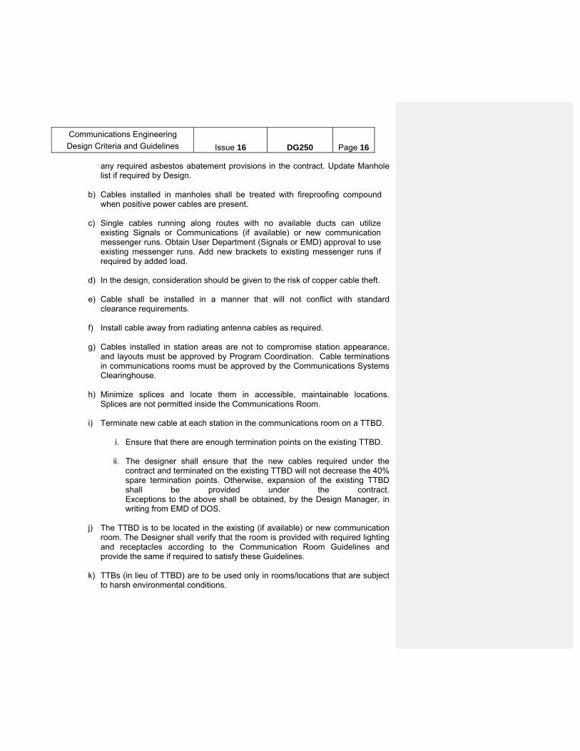
Telephone Cable Contracts provide for the installation of cables running mainly in areas along the right-of-way and sometimes extending into yards and/or facilities. See Figure CA-1 for a typical telephone cable key plan.
1. Guideline for limits of cable runs: a) Cable run limits shall be as per the scope of work. However, care shall be
taken to insure a continuous run to main hubs and/or PBX locations and/or fiber optic nodes.
b) In general, all cable runs along the right-of-way shall be local, i.e., cable shall
be terminated at every station. No express cable shall be run unless clearly
Communications Engineering
Design Criteria and Guidelines
Issue 16
DG250
Page 15
scoped for a specific reason (express cables are terminated at selected stations along the line).
c) Cable runs shall be coordinated with existing and future runs to comply with
the requirement in (a) above and satisfy user requirements. 2. Guidelines for Cable Size (Gauge and number of Pairs): a) Where engineering considerations allow, all cables installed along the
right-of-way shall be #22 AWG, solid copper conductor, twisted pair cable as per NYCT Wire and Cable Specification TC.
b) Cables installed with linear cable lengths within the station envelope shall use
# 22 AWG, solid copper conductor, and twisted pair cable as per NYCT Specification TC. The cable shall be terminated at a TTB/TTBD using IDC connector blocks.
c) For terminal blocks where each terminal is isolated, use four position bridge
clips (metallic) for pass-through cables and two-terminal clips. d) Where vibration is a concern use bridge clips on all terminals that are punched
down or screw down blocks that accept #22 AWG, e) All cables installed along the right-of-way under telephone cable contracts
(excluding EA cables) shall typically be 100 pairs. A 150 pair cable is preferable if budget allows. User (Electronic Maintenance Division of MOW) must be consulted as to number of cable pairs, including spares required.
f) All new copper cable installations, unless otherwise requested by the user
department, shall meet a minimum requirement of:
i. 25 pair #22 AWG cable from communications room TTB/TTBD to any facility.
ii. Quad(s) #22 AWG from Emergency Alarm TTB to Emergency Alarm units.
iii. 25 pair #22 AWG cable in/out at each Emergency Alarm TTB. 3. Guidelines for Cable Installation a) Cables shall be installed in ducts whenever possible. Racks and insulators shall
be provided in manholes for racking the cables. Request the Cable Section to verify that the proposed duct runs (assignment) are clear and available for use as designed. Supply the Design manager’s office with a list of Manholes to be utilized and request his office to coordinate with Environmental the inclusion of
Communications Engineering
Design Criteria and Guidelines
Issue 16
DG250
Page 16
any required asbestos abatement provisions in the contract. Update Manhole list if required by Design.
b) Cables installed in manholes shall be treated with fireproofing compound
when positive power cables are present. c) Single cables running along routes with no available ducts can utilize
existing Signals or Communications (if available) or new communication messenger runs. Obtain User Department (Signals or EMD) approval to use existing messenger runs. Add new brackets to existing messenger runs if required by added load.
d) In the design, consideration should be given to the risk of copper cable theft. e) Cable shall be installed in a manner that will not conflict with standard
clearance requirements. f) Install cable away from radiating antenna cables as required. g) Cables installed in station areas are not to compromise station appearance,
and layouts must be approved by Program Coordination. Cable terminations in communications rooms must be approved by the Communications Systems Clearinghouse.
h) Minimize splices and locate them in accessible, maintainable locations.
Splices are not permitted inside the Communications Room. i) Terminate new cable at each station in the communications room on a TTBD.
i. Ensure that there are enough termination points on the existing TTBD.
ii. The designer shall ensure that the new cables required under the contract and terminated on the existing TTBD will not decrease the 40% spare termination points. Otherwise, expansion of the existing TTBD shall be provided under the contract. Exceptions to the above shall be obtained, by the Design Manager, in writing from EMD of DOS.
j) The TTBD is to be located in the existing (if available) or new communication
room. The Designer shall verify that the room is provided with required lighting and receptacles according to the Communication Room Guidelines and provide the same if required to satisfy these Guidelines.
k) TTBs (in lieu of TTBD) are to be used only in rooms/locations that are subject
to harsh environmental conditions.
Communications Engineering
Design Criteria and Guidelines
Issue 16
DG250
Page 17
FIGURE CA-1 TYPICAL TELEPHONE CABLE KEYPLAN

Communications Engineering
Design Criteria and Guidelines
Issue 16
DG250
Page 18
B. EMERGENCY ALARM (EA) SYSTEM Emergency Alarms are devices along the right-of-way that enable
employees to remove traction power from the third rail, in case of emergency, by pulling a lever on the alarm box. Communications Engineering is responsible for providing the design for emergency alarms and the necessary wiring up to and including a telephone terminal box in the Power Substation.
Presently, the Authority is using electro-mechanical type emergency alarm
units (boxes) of a design dating to the early 1900s. The basic unit is a single unit EA. Multiple type units, controlling more than one zone, are also used. The double and triple units are equipped with micro-switches riding the same mechanism. A double has one micro-switch to control a second zone, and a triple has two micro-switches to control two additional zones. Multiple emergency alarms (with Micro switches) shall have their noninterference device disabled (strapped) to allow for removing power from a second zone following the removal of power from the first zone by a different emergency alarm unit.
1. Guidelines for System Design (see typical system Schematic Figure EA-1) a) Zone limits, location of Power Substation Control Panels (provided under the
Power Design portion of contract) and location of multiple emergency alarm boxes must be coordinated with and based on the Power Design Division’s drawings.
b) Emergency alarm box numbers shall be assigned by EMD of DOS. Every
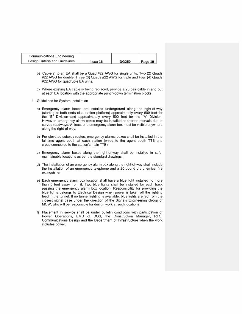
care must be taken to avoid repeating a box number anywhere in the system. 2. Existing Typical System Wiring (See Existing Typical System Wiring Figure EA-2) a) Emergency alarms are either to be connected directly to the nearest TTB or
spliced into the emergency alarm cable, usually a 25-pair or 12-pair cable installed under a Power/Emergency Alarm Contract. See Typical EA Splice Figure EA-3 for typical EA cable splicing.
b) Cable to an emergency alarm shall be a 6- pair for single units and a 12- pair
for double, triple and quadruple units. Each pair is usually used as a single conductor.
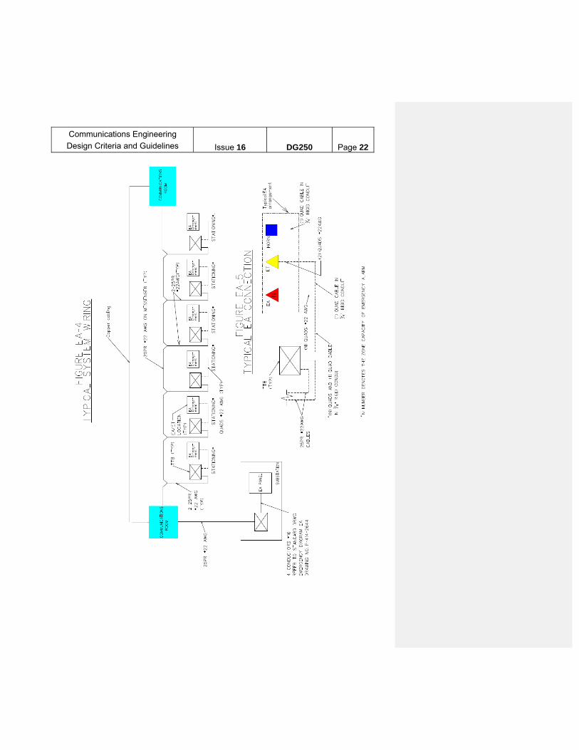
3. Typical New EA arrangement and Wiring (see Typical System Wiring On
Messenger Figure EA-4) a) Each EA box shall be connected directly to its associated TTB. See Typical EA
Connection, Figure EA-5.
Communications Engineering
Design Criteria and Guidelines
Issue 16
DG250
Page 19
b) Cable(s) to an EA shall be a Quad #22 AWG for single units, Two (2) Quads
#22 AWG for double, Three (3) Quads #22 AWG for triple and Four (4) Quads #22 AWG for quadruple EA units.
c) Where existing EA cable is being replaced, provide a 25 pair cable in and out
at each EA location with the appropriate punch-down termination blocks. 4. Guidelines for System Installation a) Emergency alarm boxes are installed underground along the right-of-way
(starting at both ends of a station platform) approximately every 600 feet for the “B” Division and approximately every 500 feet for the “A” Division. However, emergency alarm boxes may be installed at shorter intervals due to curved roadways. At least one emergency alarm box must be visible anywhere along the right-of-way.
b) For elevated subway routes, emergency alarms boxes shall be installed in the
full-time agent booth at each station (wired to the agent booth TTB and cross-connected to the station’s main TTB).
c) Emergency alarm boxes along the right-of-way shall be installed in safe,
maintainable locations as per the standard drawings. d) The installation of an emergency alarm box along the right-of-way shall include
the installation of an emergency telephone and a 20 pound dry chemical fire extinguisher.
e) Each emergency alarm box location shall have a blue light installed no more
than 5 feet away from it. Two blue lights shall be installed for each track passing the emergency alarm box location. Responsibility for providing the blue lights belongs to Electrical Design when power is taken off the lighting feed in the tunnel. If no tunnel lighting is available, blue lights are fed from the closest signal case under the direction of the Signals Engineering Group of MOW, who will be responsible for design work at such locations.
f) Placement in service shall be under bulletin conditions with participation of
Power Operations, EMD of DOS, the Construction Manager, RTO, Communications Design and the Department of Infrastructure when the work includes power.

Communications Engineering
Design Criteria and Guidelines
Issue 16
DG250
Page 20
FIGURE EA-1 TYPICAL SYSTEM SCHEMATIC
Communications Engineering
Design Criteria and Guidelines
Issue 16
DG250
Page 21
FIGURE EA-2 EXISTING TYPICAL SYSTEM WIRING
FIGURE EA-3
TYPICAL EA CABLING SPLICE
Communications Engineering
Design Criteria and Guidelines
Issue 16
DG250
Page 22

Communications Engineering
Design Criteria and Guidelines
Issue 16
DG250
Page 23
C. TELEPHONE SYSTEMS / SETS
The backbone of the Authority telephone system consists of six (6) Northern Telecom MSL-100 digital electronic PBX's, an Avaya Aura Call Manager and Avaya Media Gateways installed at 370 Jay Street and an NEC NEAX 2400 IMS UMG digital electronic PBX installed at Livingston Plaza. The locations of the six (6) Northern Telecom Switches are:
333 West 53rd Street Coney Island Yard 207th Street Yard Roosevelt Ave. Station East New York Bus Depot East 180th Street Yard
1. Telephone Sets - General. Local Any standard single line set can operate with the above switches. Additionally, each PBX operates with multi-button phones that are designed specifically for that PBX model. The multi-button sets are of two types, electronic analog and digital. The digital sets have been specified for the switch installation sites. These digital sets have a limited range of about 2000-3000 feet from the PBX. The switches are equipped with line cards for both the single line sets, and the multiple button digital sets.
a) All new telephone sets shall be provided and programmed with all required
features. b) Any sizable installation in the vicinity of a PBX site should bring new cable
back to the MDF in the PBX room. c) All station (telephone) cable runs should be 4- pair category 6 and terminated
on an RJ 45 jack at the station location. In general, only one pair will be required for analog telephone service. The remaining pairs are for special requirements and to provide spares.
d) Single line sets can be programmed with features at the PBX, such as call
pickup, call forwarding, and conference calls. User groups should be made aware of this fact to minimize the demand for multi-button units.
2. Remote Locations (Greater than 3000 ft. from PBX)
For facilities with more than a few telephone sets, electronic key telephone systems should be specified to minimize the number of copper pairs required to run back to the PBX or fiber optic node. To avoid the proliferation of different types of key systems, resulting in maintenance difficulties, three system families are to be specified, as described below. Specified PBX line cards should be for
Communications Engineering
Design Criteria and Guidelines
Issue 16
DG250
Page 24
single line sets for all key systems. Also, for all key systems a jack is available on each key system line card that provides POTS (Plain Old Telephone Service) should the electronics fail. Specify that the Contractor shall furnish and install a single line station set with cabling to each of these jacks. Provide for a UPS for the telephone system with duration depending on facility type, user requirement and availability of emergency generator. In determining the appropriate equipment, the engineer should consult the manufacturer’s latest literature and should design with capacity for future growth. Consider in consultation with EMD Telecommunications Planning & Installation Group of DOS the use of VOIP capable telephone systems and telephones.
Where VOIP capable telephone system is furnished, Emergency Type hardened analog phones will still be required for environmentally harsh locations such as Fan Plants, Pump Rooms, Deep Wells, Outside Station Service Center Booth.
D. PASSENGER STATION PUBLIC ADDRESS SYSTEM
1. General.
The latest generation Passenger Station Public Address (PA) System is currently (December, 2006) being installed at most Division “A” stations. This is a data-based system that may be thought of as a wide area network (WAN) operating over the fiber backbone and sharing it with other network applications. It permits announcements to be made from both local and remote locations. (There were two previous generation systems; one was carrier-based and the other was data (control) and audio based. The latter type systems may still be installed as an interim measure at certain locations (new or to replace similar existing system) to keep the existing key arrangements; the loudspeakers and ambient sensing microphones would, however, be installed in accordance with the most recent design criteria and remain to operate with the final system, as described herein. The carrier based system will no longer be used.) See the master contract specifications for equipment and system characteristics. A future project(s) for Division “B” Stations is (are) also being planned but the system type has not yet been determined.
2. Loudspeakers and amplifiers.
The standard loudspeaker is a wall mounted or ceiling mounted speaker which complies with UL1480 listed for use in Fire Alarm and/or Emergency Communication Systems. These are located every 15 feet along the station platform in the subway. At elevated stations, the loudspeakers are installed every 15 feet along the entire length of the canopy. Speakers extending past the length of the canopy shall be mounted on lighting poles as shown on architectural drawings for “Light Poles with Speaker Details for Island and Side Platforms”.

Communications Engineering
Design Criteria and Guidelines
Issue 16
DG250
Page 25
Wire the loudspeakers so that alternating loudspeakers are wired to the same amplifier channel, in accordance with the Authority’s standard for loudspeaker wiring. Provide at a minimum (1) spare amplifier zone per station. The northbound platform, southbound platform and each mezzanine control area shall be a separate zone. Run a spare twisted pair speaker cable to each speaker zone.
The station’s control areas are also covered, usually by three loudspeakers on each side of the turnstiles. In general for system expansion projects, other areas of the station (e.g., mezzanine, stairways, passageways, escalators, concourse areas) shall be covered by the PA system to be compliant per code.
3. CIS Units.
Customer Information Screens (CIS) are provided in new Public Address System to display visual information that duplicates and/ or complements the audio announcements.
The location and type (single-sided, double-lined, double-wide, etc) of CIS units required for each platform are determined by a survey conducted by Operations Planning and CPM/ Best Practices and Strategic Improvement Departments. .
4. Ambient sensing microphones.
Ambient sensing microphones detect the ambient noise level at the station and adjust the volume accordingly so that PA announcements may be audible. An ambient sensing microphone is installed at each platform end where the train enters the station, and each mezzanine control areas.
5. Workstations.
Dispatchers and other required personnel who are located at or near the station each receive a computer workstation equipped with a microphone to enable them to make announcements.
6. Backup Power.
The PA system cabinet shall be fed with power through the station Communications Room power plant which will provide for two hours of backup power. If no power plant is available provide a dedicated 2 hour UPS for the PA system.
7. Special Requirements.
If the station Public Address system is to serve as the voice evacuation system during a fire or evacuation emergency, a variance shall be obtained for such use. Where such capability exits for the public address system type, the PA system will also be utilized to remotely activate the fire alarm system at a station via the head end PA workstation. The two systems must be closely coordinated.
Communications Engineering
Design Criteria and Guidelines
Issue 16
DG250
Page 26
8. Cabinet Provisions
a) The cabinet shall be equipped to, automatically and without operator intervention, trigger the equipment to gracefully shutdown, as per the equipment manufacturer operational feature, in case of:
i. Power loss and depletion of backup power.
ii. Inside cabinet temperature reaches preset high temperature.
b) The cabinet shall be equipped to, automatically and without operator intervention, trigger the equipment to start up once the:
i. Power is restored and
ii. Inside cabinet temperature reached preset operating temperature.
E. SECURITY/ACCESS CONTROL AND INTRUSION DETECTION ALARM SYSTEM
Security alarm systems are installed to protect certain facilities such as Stations, Shops, Bus Depots, Signal Rooms/cabinets, etc., as required by the User and Property Protection. They are designed to detect intrusion, sound an alarm, and to notify security monitors of the event. A security alarm system is also used to separate public from critical non-public spaces inside stations and terminals.
These systems may also be designed to create multiple levels of electronic security to protect infrastructure and equipment, rooms, and other areas critical to operations and protection of the traveling public. These systems may include:
Access control card readers
Intrusion detection zones
Video analytics (combined with video surveillance described in paragraph F below)
Specialized sensors to protect specific assets
Card readers w/keypads to control sensor zones or for a higher level of access control
The systems will have the ability to permit access to authorized individuals, deny entry to those personnel not authorized access, allow configuration to permit entry only during certain times, and permit system administrators to immediately delete an individual’s access authorization.
Electronic security systems will, in most cases, report events to a Regional Control Center for management of devices and for coordinating response to alarms and
Communications Engineering
Design Criteria and Guidelines
Issue 16
DG250
Page 27
monitoring maintenance of the system. In cases where the alarm system is either temporary, or where effective communications links are not available, a stand-alone system may be necessary.
A “typical” Electronic Security System will include the following system components:
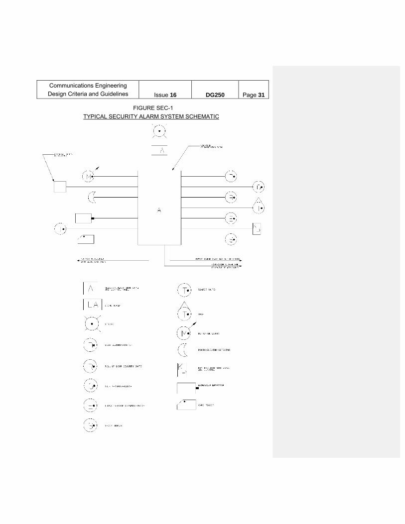
See Figure SEC-1 for Typical Security Alarm System Schematic.
1. Alarm Panel(s) (also referred to as Intrusion Access Control Panel)
a) The alarm panel provides the ability to control multiple access control devices and sensor components. Most manufacturers’ product lines offer different size panels to meet the needs of different applications. Size the panel as needed for the application, and provide a minimum 50% expansion capability without adding new hardware.
b) The alarm panel shall provide a means of identifying the location of an incoming alarm.
c) Each panel will communicate with either another panel within the system or with the system head-end at the monitoring location.
d) If applicable, the alarm panel should be capable of communicating with a remote computer (at a control center) to transmit and receive controls/indications or programming instructions using Internet Protocol (IP) based communications.
i. Intrusion notification shall be sent to RCC MoW CAMS.
ii. Manual Silencing of alarms will only be at RCC MoW CAMS.
e) Alarms generated by the electronic security system must alert operators at the alarm monitoring location of the alarm condition. A visual display of the alarm and an audible signal for the operator are required.
f) The ability to manually silence alarms from the monitoring position shall be provided.
g) Each panel will be equipped with a minimum 4-hour battery back-up power supply.
2. Alarm Points
a) Locations with access control shall be equipped with local audible alarms (horn or sounder) and strobes inside the room.
i. Strobes for access control strobe lights shall be blue.
Communications Engineering
Design Criteria and Guidelines
Issue 16
DG250
Page 28
ii. Horn sound /sounder shall differ from those used to sound Fire Alarm System horn sound Alarms.
iii. Local alarms shall activate for 30 seconds unless turned off by the system monitor.
b) Emergency exits shall be equipped with an emergency exit alarm. Provisions shall be made for remote signaling of the door opening, if required. For new emergency exits, alarms should not have "push to open" handles, because these doors are being equipped with panic bars.
c) At certain locations, in order to enforce the use of an exit as an emergency exit only, CCTV monitoring and recording of the exit may be required.
d) Where magnetic type security switches are required. Do not use plunger type switches, as there is a risk that these will not open due to sticking.
e) Overhead or roll-up doors should be protected by roll-up door security switches, as required. For roll-up doors with security grills, the grills shall also be protected by security switches. Roll-up door switches should be of the wide gap type to permit movement due to wind load-without alarming.
f) Elevator doors should be protected by a suitable security device, if required.
g) Gates should be protected by security contacts designed for gates, if required.
h) Vaults should be protected by vault contacts, if required.
I) Motion detectors should be of a type designed to minimize false alarms, e.g., dual technology type.
j) Remotely located alarm system enclosures should be protected by tamper switches, if required.
k) Fences and outer walls should be protected by shock sensors if required.
l) Signaling and Communication Rooms shall be provided with access control and intrusion detection and CCTV.
m) Communications lines must be protected against interference or damage. Use end-of-line resisters and tamper devices to alert system monitors of intrusion attempts or communication signal interruption.
n) Loss of primary power must create an alarm at the monitoring position.
o) The security alarm system shall be connected to both the primary and emergency backup power systems.

Communications Engineering
Design Criteria and Guidelines
Issue 16
DG250
Page 29
p) Where required by the user or Property Protection, provide seismic sensors to monitor the integrity of fences and outer building/room walls.
3. General
a) If the system is required to meet a UL standard of security, all conductors shall be installed in conduit.
b) Security alarm equipment shall not have batteries as a prime source. All units shall be hard-wired to their power source. The security system shall, however, be equipped with battery back-up. Duration of battery backup shall be determined during scope development based on type of facility, user requirement and availability of emergency generators.
c) The standard cabling is #18 AWG stranded for alarm installations in facilities. Spare pairs shall be provided in the security system cabling.
d) For facilities/locations where certain alarm zones are not 24 hr. zones, the system shall provide a means to bypass zones.
e) Appropriate signage - (e.g. identification of emergency exits, identification of door numbers to agree with alarm zone numbers, warning signs for intruders) - shall be provided.
f) As a general rule for a facility, one door is designated as the entrance and exit. Every other perimeter door should be protected by an alarm device.
g) The security alarm system may include access control, if required and in accordance with the International Building Code and NYS Uniform Code Supplement approved for the project.
i. Doors that are provided with UL Listed fire exit hardware that provide “free egress” (no special knowledge or keys to open the door) are not required to be connected to a fire alarm system.
ii. Certain buildings may have locked stairway re-entry doors. These doors shall be connected to the fire alarm system.
iii. Fail safe electrical and control wiring applies.
h) In general, areas protected by security alarm equipment do not require dedicated CCTV surveillance. However, if required, the security alarm system shall be interfaced with a CCTV system. Interfacing the systems permits the following capabilities:
i. A CCTV video camera viewing an alarm zone area may be displayed on screen and recorded upon activation of the alarm zone.
Communications Engineering
Design Criteria and Guidelines
Issue 16
DG250
Page 30
ii. A minimum of 10 seconds pre-alarm video must be provided.
iii. A CCTV video camera viewing a card reader area may be displayed on screen upon use of the card reader.
iv. Information about a cardholder, with the cardholder’s photograph, may be displayed on screen when that card is used at a card reader.
v. Where required, a camera is provided to validate a person’s appearance with photos stored in the access control (or other) database.
i) If there is sufficient manpower available at the monitoring location, the system may be designed to require personnel to reset the tripped alarm device at the device location (such as a local alarm). Otherwise, the system must permit remote resetting.
j) If required, a method of communication must be provided between the monitoring location and areas protected by the alarm system. This may be a talk-back speaker system.
k) All hardware shall be tamperproof.
l) The alarm system shall be monitored continuously.
m) Provide appropriate door locking hardware as per DoS Access/Intrusion Door Lock Design Guidelines
n) Door locking hardware shall meet Department of Subways (DoS) TG-901 requirements for locks installed in DoS facilities.
Communications Engineering
Design Criteria and Guidelines
Issue 16
DG250
Page 31
FIGURE SEC-1
TYPICAL SECURITY ALARM SYSTEM SCHEMATIC
Communications Engineering
Design Criteria and Guidelines
Issue 16
DG250
Page 32
F. CCTV SYSTEM
Systems shall be provided at passenger stations, facilities or locations as required by various departments. For projects where a new Closed Circuit Television (CCTV) System cabinet(s) will be provided and the Communication room(s) is not environmentally controlled, provide a Category 6 RJ-45 Ethernet jack for the CCTV system to access the NVR via network switch without opening the cabinet. For a 6 foot CCTV cabinet, the RJ-45 Ethernet jack shall be located on top of the cabinet above the air-conditioner on the hinge side of the door. For a 7 foot CCTV cabinet, the RJ-45 Ethernet jack shall be located on the cabinet door above the air conditioner on the hinge side of the door. A field survey should be performed to determine if there are any constraints for the proposed location of the RJ-45 Ethernet jack. If one exists, then the Design Manager should bring this to the attention of the user department and coordinate for a solution. For projects where a new Closed Circuit Television (CCTV) System cabinet(s) will be provided and the Communications room(s) is environmentally controlled such as System Expansion projects, the Program Area Design Manager should coordinate with the user department to determine if a RJ-45 Ethernet jack will be required.
1. Type of system
a) The purpose for the system must be clearly established (e.g., passenger security, passenger ID, car door clearance, elevator/elevator landing monitoring, other applications). This in turn will determine camera placement, whether or not video recording is required, whether or not the system needs a UPS, and other factors. For passenger ID CCTV system, follow the requirements of the Master Specifications for this system.
b) The CCTV architecture design shall be IP based.
c) The CCTV system shall permit expandability of 40% additional cameras and recording capacity.
d) Support IP networking equipment and consequent network management tool marketplace.
e) Support open-platform video recording hardware and software.
f) Utilize PoE (Power over Ethernet) per latest 802.3 revision (currently 802.3af), allowing one cable to carry both power and data.
g) Support multiple digital video standards and megapixel image resolutions beyond CIF formats. CIF Support shall be required as baseline.

Communications Engineering
Design Criteria and Guidelines
Issue 16
DG250
Page 33
h) Bidirectional data transmission allowing PTZ (pan, tilt, zoom) commands transmitted to cameras as well as device status transmitted to control point via the same data cable.
i) On-board automated alerting from the camera triggered via either in-scene video motion detection or dry-contact discrete inputs.
j) Support real-time, continuously variable bitrates for every camera.
k) When required, support for embedded in-picture video analysis with motion detection and profile recognition as applied to objects, people, and vehicles.
l) Support integration of video surveillance with other systems such as access control, alarm systems, building management, etc.
m) Installations with field-upgradeable products, whether at the device or centrally distributed over the IP network. Options shall be selectable to authorized craft personnel.
2. Camera locations
a) Video cameras shall be of the fixed or variable focal length type unless otherwise required. As a general rule, pan/tilt/zoom cameras shall be used when area to be covered is large and no continuous viewing is required. Lenses for outdoor areas shall be auto-iris type.
b) Cameras and their enclosures shall be suitable for the environment where the cameras are to be installed. In general, avoid using heaters in camera enclosures. Maintenance personnel report that heaters fail often, that heated camera housings attract pigeons in the cold weather, and that outdoor cameras continue to operate during the winter even without the heaters.
c) In general, video cameras shall use CCD or CMOS imagers, output progressive scan video, and be dome type.
d) Cameras are generally provided in the following areas, depending on the specific scope of the project:
i. Passenger Identification (PID): CCTV cameras are to be provided to obtain images of the required views and quality at each turnstile, agent operated gate, (AOG), service gate, High Entrance Exit Turnstile (HEET) and High Exit Turnstile (HXT), and any other transition used to pass between the Paid and Unpaid sides of the Control Area. Reference Table 1.1 in Appendix A for common PID scenarios.

Communications Engineering
Design Criteria and Guidelines
Issue 16
DG250
Page 34
1. In the event where there is a new fare array being built and there is an existing fare array without PID CCTV system, PID CCTV shall be installed at both fare arrays to ensure full coverage of the station.
2. In the event where there is a new fare array being built and there is an existing fare array with PID CCTV system, PID CCTV shall be installed at the new fare array location to ensure full coverage of the station.
3. PID cameras shall be installed at all station exits if such exits are not already covered by the fare control cameras.
4. PID cameras shall be installed at all station exits and only be located on the unpaid side, facing towards the exit point for high exit turnstiles (HXT).
5. There shall be a minimum of 1 camera per two turnstiles and 1 camera for each HEET/HXT or gate. The cameras are required on each side of the fare array per each direction.
ii. Communications and Signals Signal Rooms: It is a NYCT policy to provide monitoring and surveillance functions only in these new mission-critical rooms. New Signal rooms and communication rooms/closets housing active electronic equipment shall have CCTV cameras, to be recorded locally, located: a) inside the room monitoring the entrance(s) b) Inside the room monitoring all aisles in the room c) Outside the room monitoring entrance (s) to the room
iii. Entrance to public emergency egress stairs: Emergency stairs, through back of house locations, are normally closed to the public. CCTV cameras shall be provided at the demarcation area between the public area and non-public area that leads to a stairway. Cameras shall capture the movements in and out of such areas.
Communications Engineering
Design Criteria and Guidelines
Issue 16
DG250
Page 35
iv. Elevator Cab: All elevators cabs are to be provided with a camera facing the direction of the elevator entry/exit point(s). Elevators having more than one entrance/exit shall be equipped with one (1) camera per entry/exit point.
v. Locations where required by the user: Provide CCTV coverage at locations where such coverage is required by the user for specific functions.
vi. Elevators Landings: All elevators landing with the exception of open street level landings shall be equipped with CCTV coverage. Where possible and in coordination with NYCT ADA office, consolidate CCTV cameras for elevator landing coverage and CCTV cameras associated with elevator landing Help Points.
vii. AFAS Gates: AFAS gates shall require CCTV coverage on both side of the gate, interconnected to the AFAS speakerphone. The system shall function similar to the elevator application of same. The scope of AFAS coverage is limited to the control area where new or rehabilitated elevators are provided. Since the AFAS CCTV replicates PID coverage, consideration shall be given to the expansion of CCTV to provide PID coverage for the entire control line, in coordination with F.2.d.i (CCTV System) above and H.4 (Speakerphone Systems).
viii. Platform Edge – OPTO (One Person Train Operation): All station with OPTO shall install cameras at the platform edge to assist the Operator. Monitors for OPTO should be located at the Operator’s position in the front of the train. New stations and station Rehabilitations installing CCTV systems should consider installation of infrastructure only for future OPTO.
ix. Platform Edge - Curvature: All station with impaired platform edge line of sight due to platform curvatures shall be surveyed for platform edge camera to assist the train Conductor with door operations. Monitors for these cameras should be located at the Conductor’s position.
x. Situational Awareness: Where required by the Department of Security (NYCT or NYPD) provide PTZ cameras to assess alarms generated by access control and intrusion detection zones (if not within the view of other cameras), and at platform and mezzanine levels of stations to aid police. Video streams from these cameras are routed to the NYPD control center. CCTV video traffic will be connected to NYPD if at least one of the following conditions hold:
Communications Engineering
Design Criteria and Guidelines
Issue 16
DG250
Page 36
a) NYPD has (or will install) a lateral into the station as part of the contract.
b) COE network is available to transport video to the nearest existing NYPD lateral.
xi. Long passageway: Generally, if a corridor or passageways is more than 50 feet long and is not open to the view of a platform or a station agent then a camera shall be considered at that location.
xii. Under River Tunnel (URT) Booths and End of Platform (EOP) Cameras: CCTV coverage is required to capture movement from in and out of all URT entrances. If Station is assessed as high risk, provide End of Platform (EOP) cameras for entrances from the platform to the tunnel, EOP and URT cameras shall be integrated with ESS intrusion access and motion surveillance security systems.
3. Monitoring Locations and Monitors
a) The CCTV system shall be interfaced with other equipment or systems as required (e.g. ADA speakerphone system, security system).
b) The design shall provide for:
i. Digital video-recording, if required.
ii. Monitors for use by train operators/conductors to monitor car door clearance. The monitors shall be sun-readable type displays, on elevated stations.
iii. Monitors for use by Dispatchers to monitor train ID
iv. Monitors for use by NYPD at URT Booths (under river tunnel tub entrance) locations. URT / EOP cameras shall also be monitored remotely at C3 security location.
v. UPS backup power based on type of facility, user requirement and availability of emergency generator.
vi. Surge Protection for outdoor cameras, camera enclosures and central equipment locations.
c) CCTV System Central equipment shall be installed in a cabinet in the communication room for the station or the facility. Heat dissipation within the cabinet shall be addressed in the design in order to avoid exceeding equipment operating temperatures.

Communications Engineering
Design Criteria and Guidelines
Issue 16
DG250
Page 37
4. Cabinet Provisions
a) The cabinet shall be equipped to automatically and without operator intervention trigger the equipment to gracefully shutdown, as per the equipment manufacturer operational feature, in case of:
i. Power loss and depletion of backup power.
ii. Inside cabinet temperature reaches preset high temperature.
b) The cabinet shall be equipped to automatically and without operator intervention trigger the equipment to start up once the:
i. Power is restored and
ii. Inside cabinet temperature reached preset operating temperature.
G. FIRE DETECTION / ALARM SYSTEM
1. Associated Guidelines, Specifications and Codes (use latest edition as applicable. Verify the year of edition for each of the following codes, standards and guidelines)
a. International Building Code and New York State Uniform Code Supplement approved for the project b. NYC Building Code (pertaining to cable approvals) c. NFPA 72 d. NFPA 2001 e. NFPA 70 f. NFPA 13 g. NFPA 750 h. UL 864 i. DG 306 (Escalators) j. DG 307 (Elevators) k. DG 310 (Rail Maintenance Facilities) l. DG 401 (Bus Depots) m. DG 405 (Stations) n. DG 311 (Clean Agent Suppression Systems) o. OSS Station Renovation Design Guideline for Fire Alarm Systems p. Communications Engineering Code Compliance Checklist q. Communications Specification section 19K
2. Design Accountability
a) All designs in general shall be performed by NYCT in accordance with this guideline, Code, user requirements, and maintenance requirements in order to achieve safe and reliable fire alarm protection for customers, employees, NYCT property and continuity of NYCT mission critical operation.

Communications Engineering
Design Criteria and Guidelines
Issue 16
DG250
Page 38
b) Designs by outside consultants on NYCT projects are subject to the same
paradigm as the above with added requirements that all design “engineering judgment” are concurred with by NYCT.
c) Designs that address Outside Project interfaces to NYCT property are not
subject to this fire alarm guideline but must still be reviewed by NYCT to address potential coverage overlaps and user concerns on the intent of fire alarm protection in the adjoining areas.
3. Design Documentation and Drawings
a) Fire alarm design drawings shall include
1. General notes that include a general scope of work and installation requirements.
2. Applicable symbols and abbreviations
3. System riser
4. System Operational Sequences with specific interface identifiers for elevators, air handlers, etc.
5. Layout drawings: Layout drawings shall allow for estimates of conduit
and device quantities and special conditions for weatherproof, explosion proof areas etc.
6. Elevation drawings for the FACP where close coordination with other
equipment and field conditions are warranted.
7. Device removal drawings, if applicable. Conduit lengths and cable shall be notated.
b) Fire alarm system calculations shall include
1. Voltage drop for notification appliance and auxiliary power circuits.
The maximum worst case voltage drop (assuming an end of life battery terminal voltage of 20 VDC at 24 hours standby) target shall be 4 VDC for notification circuits and 2 VDC for either maintained or non-maintained auxiliary relays. Cables for these circuits are unshielded pair as per specification 19D.
2. Allowable capacitances for signaling circuits shall be based on the
manufacturer’s requirements for maximum peripheral loading at a specified distance from the control panel. Low capacitance cables included in specification 19D shall be as per fire alarm system

Communications Engineering
Design Criteria and Guidelines
Issue 16
DG250
Page 39
manufacturer’s recommendations either twisted shielded pair or unshielded pair.
3. Fire detector placement and any required derating for rooms larger
than 900 sq. ft. Refer to NFPA 72. 4. Spare capacity. This is determined on a case by case basis.
4. Primary Power
The design of the fire alarm system (and associated notification appliance panels if utilized) power source and any transfer switch logic shall be referred to and completed by the Electrical Engineering Discipline subject to the following fire alarm requirements:
1. Available Voltage at the fire alarm panel shall be no lower than 110 VAC.
2. Panels shall be on separate circuits. Associated notification appliance panels may be paralleled and determined on a case by case basis.
3. The fire alarm system shall derive secondary AC power from an on-site standby generator when such a generator is installed or available. The fire alarm system will monitor the position of the transfer switch to the FACP.
4. A fused disconnect switch ahead of the facility/station service switch is preferable, but subject to the project scope of work.
5. Where access to a facility/service switch is not feasible, connection to a local dedicated branch circuit is acceptable provided that the panel is located in a secured room.
6. A tamper resistant breaker lock in device with a 1620 keyed padlock is also required.
5. Monitoring and Placement of the Panel
a) Off-site Monitoring
Remote fire alarm signals are annunciated to the existing NYCT Central Alarm Monitoring System (CAMS), a client based system comprised of client based Software House Head End. The response to, and reporting of fire, supervisory and maintenance alarm are based on established protocols. Facilities that are 24/7 are provided with DACT and IP, if feasible, connections for purposes of maintenance monitoring only.
In some instances third party central station providers are utilized for administrative and support buildings, and bus facility compressed natural gas fueling/storage areas.
Communications Engineering
Design Criteria and Guidelines
Issue 16
DG250
Page 40
New facilities with carbon monoxide detectors must report to an offsite location, either through CAMS, a third party central station monitoring service or to an adjoining facility that agrees to the monitoring. In all cases a CAMS connection is still required.
1. The fire alarm provisions shall incorporate a Digital Alarm Communicator Transmitter (for connection to telephone network) and an IP interface card that emulates the DACT (for connection to the data network). The availability of telephone line dial tones must be coordinated/verified with EMD.
For telephone connections, appropriate line cards must be provisioned
into the contract to emulate a dial tone. Telephones lines that are no longer required for a contract (i.e.- use of VOIP) are permitted and encouraged to be re-purposed for fire alarm connectivity.
2. All conduit and cabling work shall be provided to the respective
termination in the communications room. The conduit and cabling shall be shown under the Communications telephone and/or data drawings.
3. The data connection is subject to the Ethernet distance limits. The
PS-LAN, where available, shall be utilized in place of conduit installation back to the communications room.
4. For locations that have functional NYCT telephone and NYCT data
network connectivity, the system shall be routed to the data network (primary) with fall back to the telephone network (secondary).
5. For locations with no data connectivity, two NYCT phone lines shall be
provided. The IP capture card and maintenance data card shall be provided for future use.
6. For locations with no NYCT data or NYCT telephone connectivity, only
two Verizon lines shall be provided. 7. For locations with NYCT data network availability only, one data
connection shall be provided where the inclusion of a NYCT telephone installation would be prohibitive.
8. In addition to the DACT monitoring provisions, substations shall be
monitored via the SCADA system to the Power Control Center (NYCT) or St George Control Center (SIR). Two distinct alarm conditions are required- fire and fire alarm system trouble. The relay circuit is supervised by the SCADA system.

Communications Engineering
Design Criteria and Guidelines
Issue 16
DG250
Page 41
9. The fire alarm system shall be provided with a secondary data connection for IP based remote maintenance monitoring of the system. This is a different application from CAMS.
b) On-Site Monitoring Provisions
1. Station Fire Alarm Panel- monitored at the full time agent booth.
The main FACP shall be located and subject to architectural approval. The placement of the panel at another location in the station to address a field condition or scope of work limit is acceptable provided that a remote annunciator is provided at the control area and DoS Engineering and EMD concur with the location of the panel.
2. Elevator or Escalator Fire Alarm Panel- monitored at the full time
agent booth.
The FACP shall be provided in the control area subject to architectural approval but in the event that field conditions or scope limits dictate otherwise, the panel may be installed in the machine room with an annunciator installed in the agent booth.
3. Bus Depots, Car Equipment Shops, other facilities- enclosed lobby
area or other approved locations approved by DoS Engineering and EMD provided that a remote annunciator is provided at the main entrance to the facility.
In some cases, a remote annunciator may be required at the yard entrance to the facility to provide emergency responder way finding via the property protection agent in which case a radio solution may be required. Coordination with OSS and the Wireless Communications Group is needed but in general only a common alarm for each affected building will be indicated at the property protection booth.
4. Substations - monitored off site only. The panel shall be located in the substation subject to design coordination only. Two distinct alarm conditions, fire and fire alarm system trouble, shall be monitored at PCC via SCADA system.
5. Signals Areas- report off site only including installations protecting an
adjoining Tower. Installations that comprise a larger protection area for employee, office, signal and RTO areas may have an annunciator located as per OSS or user requirements.
The panel shall be installed in the Fire Suppression Room or common lobby area for the signals installation. A remote annunciator should be
Communications Engineering
Design Criteria and Guidelines
Issue 16
DG250
Page 42
considered at the entrance to the signals facility in instances where the main panel is in a fire suppression room.
6. Sprinkler Monitoring Panel- full time agent booth.
The main FACP shall be provided in the control area subject to architectural approval. The placement of the panel at another location in the station to address a field condition or scope of work limit is acceptable provided that a remote annunciator is provided at the control area and DoS and EMD concur with the location of the panel.
7. Any panel that is installed within a facility or station with an existing
master panel shall be tied to the master panel for alarm, supervisory and trouble monitoring where such monitoring capability exists on the master panel.
8. A notification appliance with a sign that indicates passersby to notify
the fire dept. or NYCT shall not be as the only acceptable form of on-site monitoring unless otherwise approved by OSS.
6. Design Approaches Fire alarm designs take several forms depending on the code and design objectives for the system.
A “new system” is preferable but funding and project realities will require a design investigation of whether an existing fire alarm system can be expanded. This is on a case by case basis with ultimate (documented) approval by EMD and OSS with consideration to:
Obsolescence Operational requirements and department jurisdictions (such as accessing
a signal room to address an alarm in an elevator machine room) Existing system at maximum capacity State of repair Critical design requirements capability (DACT, specific programming/logic
functions, etc) Single point of failure affecting the protection for many conveyance
systems (i.e.- “many” escalators on one panel) Cross alarming may still be required for an existing system to allow for
multiple panels to activate a general alarm in their respective areas. Conditions that preclude “easy” conduit placement Small systems associated with fire safety control, suppression releasing or
specific detection functions are not required to monitor other small systems. If no “large” or master panel exists at a location, there is no requirement to provide those capabilities (i.e.- general alarm for a facility) due to the installation of a “small” system in a facility or station.

Communications Engineering
Design Criteria and Guidelines
Issue 16
DG250
Page 43
Gas detection devices (hydrogen, carbon monoxide, methane) are to be integrated with the fire alarm system for initiating and notification capability as well as power requirements. This is permitted under NFPA 72 allowances as a Combination System. Notes: 1. Carbon monoxide (CO) detectors are a NYS Code requirement for all
NYCT locations with vehicle parking/maintenance facilities and/or combustion equipment .For design purposes, only new facilities will have carbon monoxide detectors connected to the fire alarm system.
2. Design and installation of carbon monoxide detection system for
existing facilities are not under the purview of CPM. Existing facilities will be remedied by NYCT in-house maintenance forces without CPM involvement.
3. The placement of carbon monoxide devices are subject to a CO
producing zone analysis conducted by the Mechanical Engineering Discipline and documented on the Architectural Code Compliance drawing sheets.
4. CO detectors and notification appliances are to be grouped by a
specific hazard zone and corresponding notification zone. The placement of CO notification appliances shall follow the general coverage of fire alarm notification appliances with adjustments made to the output capabilities of the device.
a) Five General Approaches for Station Fire Alarm Systems
The level of protection will vary for each contract and it’s incumbent on the designer to establish a high level topology of fire alarm protection to avoid coverage overlaps, monitoring lapses and a misrepresented design intent.
Not all station design projects will require fire alarm work based on code (i.e. such as Alteration 1 or 2 per EBC classification). OSS and Code Compliance should be consulted to establish the required level of fire alarm work.
Fire detection capability for station spaces includes the following: Employee facilities, electrical, mechanical conveyance, communications, concessions, refuse and storage spaces will utilize photoelectric smoke detectors. Scrubber rooms shall utilize thermal detectors. The use of heat detectors for station elevator areas are subject to approval based on the expected environmental conditions posed for the
Communications Engineering
Design Criteria and Guidelines
Issue 16
DG250
Page 44
installation such as open dampers to the exterior in an elevator shaft, partially enclosed lobby areas open to the outer air and dusty locations. Devices used in these areas shall be of the weatherproof type. Rooms that are not heated or that may be open to the atmosphere such as elevated stations are treated on a case by case basis.
1. Full area coverage as required by International Building Code,
International Existing Building Code and NYS Uniform Code Supplement approved for projects classified as New Construction, Addition or Alteration 3 shall be provided with full fire alarm protection (back of house and front of house) that may transcend the physical, “systems” and funding boundaries established by the project. The classification is assigned by the Architectural discipline and it is imperative to incorporate this in the master plan. Fire alarm signaling is defined by fire barriers but fire barriers are NOT normally provided to sub-divide station complexes hence the extent level of PA/CIS and visual alarm signaling is expected to be complex-wide, with appropriate direction from OSS or the User to sub divide evacuation zones that are served by different PA systems.
The design process and elements include:
i. Variance Requests for the following:
To utilize a new or existing NYCT Public Address (PA)
system for fire alarm audible notification. This takes the place of an Emergency Voice Alarm Communication System (applicable to Alteration 3, Additions, and New construction classifications).
To NOT install automatic fire detection devices in public areas (applicable to Addition and New construction classifications).
To NOT install manual pull fire alarm stations in public areas (applicable to Addition and New Construction Classifications. Help Points will be utilized instead.) The variances shall be identified during the SOW period or early Preliminary Engineering phase, after consultation with the User, OSS and Code Compliance.
ii. Special notification appliance arrangements
Existing or new PA system will be used for
announcements in FoH (front of house public areas) areas based on existing protocols. The Communications

Communications Engineering
Design Criteria and Guidelines
Issue 16
DG250
Page 45
PA design group must be informed for them to pursue the required modifications of the existing PA system.
Visual notification appliances in all public areas and audible/visual appliances in BoH (back of house employee and utility areas) areas. FoH notification appliance circuits must separate from BoH notification appliance circuits.
NFPA 72 visual guidelines apply with the following parameters: Inside platforms shall utilize 100 ft spacing at
15 candela (cd) Outside platforms shall utilize 177 cd devices at 100
ft and placed under the canopy only. No visual alarms shall be placed within 50 ft of the
car stop marker (longest train consist) Strobes shall be positioned facing inward on platform
edge columns and wall or ceiling mounted if there are no columns
iii. A means to manually evacuate and de-activate without
special knowledge or tools all portions of the station and/or complex simultaneously by using a special “evacuation” button (refer to specification 19K) and a co-located remote PA microphone at each of the following locations.
Agent booth (s), using the evacuation button and PA mic Responder location (s) as required by OSS, using the
evacuation button and PA mic. This is typically close to a street stair or in a Station Emergency Controls Room (new stations only). A typical above ground station will not require a responder location.
RCC, using relay logic on the PA controller. This will entail a PA controller modification and software change to allow the RTO Announcement Desk to activate and de-activate the station FoH and BoH emergency signals concurrent with an evacuation PA message.
Multiple evacuation buttons may be required to sub-divide the evacuation areas as per OSS to be in alignment with existing PA coverage zones.
Only one back of house zone is required for simultaneous notification of all back of house areas. Multiple circuits may be needed to cover all back of house areas.
iv. BoH protection comprised of fire detection, notification appliances and pull stations. The activation of BoH does NOT
Communications Engineering
Design Criteria and Guidelines
Issue 16
DG250
Page 46
automatically activate FoH alarm signals but the signals are transmitted to the agent booth and CAMS.
v. Fire safety control functions as required.
2. Limited Area Coverage primarily for BoH protection of employees as required by OSS and/or user primarily to address a specific safety concern. The key feature for this design approach is that all BoH areas are covered by automatic fire alarm devices with a general evacuation option that is initiated from the agent booth or fire department response location.
Limited area coverage systems are typically applied for replacement of existing fire alarm systems in stations that serve BoH areas but could also be applied to a project that entails a large number employee spaces.
3. Fire Safety Control Function for the protection of elevator and
escalators. Refer to DG 306 and 307.
This type of system performs a very specific control function and is comprised of smoke detection in shafts, trusses and machine rooms; sprinkler valve and elevator/escalator control along with one notification appliance in the machine room. These systems are monitored at the agent booth and CAMS. Dedicated systems are preferred for station elevator/escalator protection and the panel is permitted within the EMR ONLY if the system is in fact dedicated to elevator/escalator protection.
Smoke detector spacing and placement within the escalator truss shall be coordinated with EMD and OSS. Spacing shall be every 30 feet within BOTH sides of the escalator balustrade. One detector shall be located within each pit at the top and bottom of the escalator.
Control and monitor functions will include:
i. Passenger Station Elevators- primary recall, alternate recall, cab warning signal
ii. Passenger Station Escalators – escalator stop, sprinkler solenoid release, sprinkler pipe air supervision (if used), sprinkler pipe charged, water valve supervision (including the domestic supply valve)
iii. Facility Elevator- primary recall, alternate recall, cab warning signal, line shunt and supervision (if sprinklered)
Communications Engineering
Design Criteria and Guidelines
Issue 16
DG250
Page 47
Under no circumstances shall a Fire Safety Control System be expanded arbitrarily to address life safety/employee protection beyond the fire safety control function. An example of this approach would be a new employee locker room installed adjacent to an elevator machine room where only the machine room and locker is protected but not other areas of the station. The life safety premise in this case erroneously assumes that a fire will occur only in the machine room.
It is acceptable to expand protection to other rooms associated with mission critical protection such as EDR’s and Comm. Rooms because there is no life safety objective associated with this approach; only protection of equipment and operations. If additional protection is required for purposes of employee protection, a recommendation must be made to OSS that the design be changed to a Limited Area System. In this case, the panel is no longer deemed a dedicated elevator/escalator fire safety control panel and thus requires relocation to the outside of the EMR.
4. Sprinkler Monitoring for the protection of station areas
containing sprinklers, primarily concession areas. A sprinkler monitoring panel shall not be expanded to include arbitrary protection of adjacent areas. The system shall be upgraded to a limited area system if required.
Sprinklers installed in BoH areas are expected to be monitored by a Full or Limited Area Coverage System. The monitoring points for sprinkler protection includes waterflow switches, tamper switches and heat trace monitor panels.
5. Local Detection provides protection for single rooms associated with mission critical spaces such as Communication Rooms. This approach is on a case by case basis.
Similar to Fire Safety Control Function system, this system has a specific function which is typically limited to an automatic detection function in a mission critical space, CAMS monitoring and on site monitoring at the agent booth (determined on a case by case basis).
b) Suppression Releasing (with incidental hydrogen gas monitoring for signals locations)

Communications Engineering
Design Criteria and Guidelines
Issue 16
DG250
Page 48
1. Communications Engineering supports the Mechanical Design Discipline for the control of clean agent Inergen systems and pre-action sprinkler systems. Communications Engineering does not mandate the installation of these systems. Refer to DG 311.
2. In the majority of cases, a new releasing panel will be provided
for releasing. For Signals areas with existing Simplex 4100U systems, consideration must be given to the modification of this system which will be based on the voltage drop considerations and distance to the protected areas from a maintenance perspective.
3. Clean agent releasing systems incorporate the following
features:
i. Approved releasing panel and releasing module listed with the actuator specified by Mechanical Design discipline
ii. Manual, abort, maintenance disconnect and cross zoned smoke detection scheme per protected zone. Spaces under raised floors (i.e- data/PBX locations) may be included for releasing.
iii. Coded interior horns (60 bpm-first alarm, 120 bpm- cross
zone alarm, on steady- discharge) notification per zone.
iv. Colored interior strobe indication (white- first alarm, yellow-cross zone alarm, red- discharge alarm) to supplement audible signals. Discharge visual alarm is provided on each door leading to a protected zone. No exterior discharge strobes shall be provided where its activation would cause confusion for train operations. Where hydrogen detection is provided, a blue exterior strobe will be used for each door. Where an exterior strobe cannot be used due to potential confusion to train operators if the door opens into the ROW, it will be placed above the door on the inside.
v. Interfaces to HVAC, fans and dampers for shutdown and
containment of the agent release. vi. Hydrogen detection for battery areas where electrolyte
capacity exceeds 50 gallons are included with releasing panel. The hydrogen detector activates designated

Communications Engineering
Design Criteria and Guidelines
Issue 16
DG250
Page 49
exhaust fans (a fire suppression fan stop overrides fan start in the control logic).
Hydrogen alarms do not activate the suppression system.
4. Pre-action or deluge sprinkler releasing systems incorporate the
following features
i. Approved releasing panel and releasing module listed with the actuator specified by Mechanical Design discipline.
ii. Maintenance disconnect capability per zone. Abort is not
permitted but manual release may be required for a deluge type system.
iii. Monitoring of sprinkler riser components (air pressure
supervision, waterflow, tamper switches).
iv. Detection scheme utilizes linear heat detection for exposed sprinkler pipes and spot thermal detectors for concealed piping.
v. Systems are not cross zoned
5. Water mist releasing systems incorporate the same features as a pre-action releasing system but the controls may vary. Close coordination with the Mechanical Design discipline and OSS is required.
6. Releasing system panels are generally dedicated to releasing
functions only. However, there are circumstances, reviewed on a case by case basis, where a releasing panel may also provide ancillary protection and notification for rooms adjacent to the non inergen protected spaces. Additional peripherals are permitted to be added provided that they are properly identified on the matrix drawing as not serving a releasing function. The intent of this requirement is to avoid installing a separate fire alarm system for a few additional smoke detectors and notification appliances. This type of application will normally be seen with Signals related structures.
c) Smoke Control, Smoke/Heat Venting, Control of Smoke Spread in Ductwork and Raised Floors, Smoke Purge, Combustible Gas Purge
The systems below are subject to the Mechanical Design Discipline requirements.
Communications Engineering
Design Criteria and Guidelines
Issue 16
DG250
Page 50
Global HVAC shutdowns or isolated shutdowns for mechanical systems that do not circulate air beyond one room must be carefully considered prior to design inclusion as such shutdowns may result in a needlessly complicated fire alarm design, or a collateral unsafe condition, such as ventilation stoppage in fuel and bus storage areas. A fire alarm system that proceeds with erroneous and non-required shutdowns shall be deemed as a poor and unacceptable design.
1. A smoke control system maintains life safety tenability during a
fire. The smoke control system is comprised of the following elements:
i. Zoned control of fans and dampers using fire
detectors. ii. Control, fault, and power availability monitoring of fan
components. iii. Manual ventilation override and graphical status of
systems at the fire alarm control panel.
A station emergency exhaust system shall not be construed as a smoke control system and is not subject to these provisions unless otherwise required by Mechanical Design.
2. A smoke/heat venting system facilitates the firefighting process
by allowing the release of heat and smoke in large industrial buildings such as a bus depot. It is typically comprised of the following elements:
i. Zoned fan control using sprinkler waterflow switches
ii. Manual ventilation start/stop controls at an approved
location.
3. The control of smoke in ductwork is used in return air ductwork that serves more than one room and >2000 cfm. This does not apply to air handlers discharging air directly to the exterior from one space whether that space is a bus parking area or a station bathroom.
The design would entail:
ii. Duct detectors on the return ductwork to shut down ONLY
the associated unit. More than one detector may be
Communications Engineering
Design Criteria and Guidelines
Issue 16
DG250
Page 51
required due to duct detector distances from bends and splits in the ductwork.
iii. An area smoke detection system that serves ONLY the
area covered by the affected HVAC system. In many cases the use of area detection is better than duct detectors due to maintenance issues with those devices.
iv. In some cases a project may have only HVAC work at a
facility without a fire alarm system. In these cases a stand-alone duct detector and control panel will be provided at a designated location in the facility.
4. Smoke purge assists in post fire clean up and is a requirement
of the NYC Code. Smoke purge is not a requirement of the NYS Code. Where such a system already exists the fire alarm components include:
i. Shutdown of all air handlers in a fire zone via sprinkler
waterflow alarms ii. Zoned manual control and status of HVAC and dampers
from the fire alarm panel for the HVAC components associated with the purge capability.
iii. Fan re-start sequencing must be staggered
5. Raised floor areas that serve as a plenum space requires
automatic fire detection under the raised floor to stop the fan.
The detectors must be UL listed for high velocity air movement and in some cases the raised floor is protected by a suppression system. Spot area detectors shall be utilized and their placement must be coordinated with the data and a/c equipment layout to ensure maintenance access.
6. Combustible gas purge comprises of three design approaches
i. Ventilation for UPS/battery rooms. This is usually seen for
Signals and/or communications rooms with battery electrolyte capacity greater than 50 gallons for all systems in a room.
A hydrogen detector, powered and monitored by the fire alarm system via an addressable monitor modules for fault and alarm, activates the fan in the event of gas detector trouble and at 10% LEL of hydrogen which
Communications Engineering
Design Criteria and Guidelines
Issue 16
DG250
Page 52
translates to .5% maximum concentration per room volume. The hydrogen detector is placed above the power plant cabinet or above the battery rack. Multiple detectors may be required for coverage based on structural pockets and airflow arrangement. The Mechanical design discipline may request that certain hydrogen ventilation applications utilize a periodic, automated start of the exhaust fan to provide its operation, with a supervisory fault signaled back to the CAMS in the event the fan operation is not proven to the fire alarm system. An example of this would be a normally air conditioned space that also contains a normally off exhaust ventilation fan for hydrogen venting. The periodic start is once per week for a two minute run time and there are additional monitoring provisions for presence of operating power and manual initiation of the fan sequence using a test switch. Coordinate these requirements with Instrumentation and Control (I/C) Engineering discipline.
ii. Area detection for compressed natural gas bus storage,
repair and fueling areas. These systems are arranged with methane detectors that are powered by and monitored by a fire alarm system to selectively activate ventilation systems and enable fuel shutdowns and isolation. There are generally two alarm stages. The low alarm (20% LEL) activates ventilation, local supervisor’s annunciation. The high alarm (50%) removes non-essential power, evacuates the facility and notifies the Fire Dept. via central station (for fueling and compression areas). The notification scheme utilizes coded audible tones to differentiate fire and high gas as well as a common strobe signal for both.
iii. High pressure gas meter rooms. This type of design is reserved only for high pressure utility rooms in facilities and activate a fan, shutdown gas valve and sound an alarm in the facility.
Communications Engineering
Design Criteria and Guidelines
Issue 16
DG250
Page 53
d) Bus Depot and Rail Shop Protection
Bus Depots and rail shops shall incorporate the following basic protection method.
1. General notification and evacuation on all fire alarms 2. Carbon monoxide detection. See section G.6 (Design
Approaches) above. 3. Monitoring of the system as per G.5 (Monitoring and Placement
of the Panel) above 4. Shutdown of only HVAC affected by G.6 c) above 5. Manual alarms at exits only 6. Selective fire detection for electrical, communications and
mechanical rooms only 7. Shutdown of fueling systems and spraying operations by
affected zone 8. Monitoring of water based suppression systems
i. Sprinkler waterflow switches and air supervision ii. Tampered isolation valves iii. Fire pump status (running, power, loss of phase, others) iv. Water curtain/deluge systems v. Sprinkler heat trace panels
9. Shutdown of DC traction power for sprinkler waterflow alarms for affected zones in a shop
10. Monitor of eyewash alarms within the facility as required by the
user. The alarm shall be a supervisory type indication with a dedicated non fire related horn/strobe located in a 24/7 location in the shop. The remote alarm is supplemental to the local horn/strobe provided on the eyewash unit that is installed to Division 15 requirements. Coordinate with the Mechanical Design discipline to ensure that a two pole flow alarm switch is specified under Division 15.
e) Substations
Substations shall incorporate the following basic protection method
1. General notifications and evacuation on all alarms 2. Monitoring of the system as per G.5 above 3. Shutdown of air handling systems based on egress
arrangement and OSS concurrence 4. Manual alarms at exits only
Communications Engineering
Design Criteria and Guidelines
Issue 16
DG250
Page 54
5. Automatic fire detection utilizing projected beam detectors and/or spot smoke detectors. Rectifier protection is not required.
f) Signals Areas
Signal areas shall incorporate the following basic protection method
1. Coordination of suppression releasing indications with other evacuation signals.
2. Monitoring of the system as per G.5 above 3. Fire suppression design as per G.6.b) above
7. Conduit Requirements, Protection of Circuits/Pathways, Fault Tolerance
and Control Wiring
a) The evacuation requirements for a facility will dictate fire-survivability requirements for the associated conduit pathways. The survivability features include room or shaft encasement, metallic electrical protective systems and standalone fire resistance cabling.
The AHJ (Code Compliance and OSS) shall establish the required evacuation methods and the method of circuit protection will be developed.
b) The style and classification of a circuit addresses reliability from a normal
fault event, not a fire. The following are some guidelines to consider.
1. Single room protection may use Class B for signaling and notification. A large “single room” such as a bus storage area should be Class A.
2. Multiple room protection will use Class A for signaling/aux power and Class B for notification
3. Station annunciators will use Class B 4. Network nodes will use Class A 5. Where Class A may be required, an option may be to use
multiple Class B circuits for signaling and data where field conditions dictate such as crowded ceiling/conduit conditions.
6. Additional protection for short circuits (i.e. - water intrusion in signals spaces in tunnels) may be warranted. This is achieved using isolation modules.
7. Inter-building conduit runs will require overvoltage protection at both ends. Electrical Design shall determine the bond location to the grounding electrode system.
This also applies to inter-building fire alarm connections that are on messenger wire.
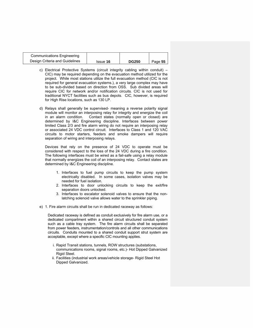
Communications Engineering
Design Criteria and Guidelines
Issue 16
DG250
Page 55
c) Electrical Protective Systems (circuit integrity cabling within conduit) – CIC) may be required depending on the evacuation method utilized for the project. While most stations utilize the full evacuation method (CIC is not required for general evacuation systems.), a very large complex may have to be sub-divided based on direction from OSS. Sub divided areas will require CIC for network and/or notification circuits. CIC is not used for traditional NYCT facilities such as bus depots. CIC, however, is required for High Rise locations, such as 130 LP.
d) Relays shall generally be supervised- meaning a reverse polarity signal
module will monitor an interposing relay for integrity and energize the coil in an alarm condition. Contact states (normally open or closed) are determined by I&C Engineering discipline. Interfaces between power limited Class 2/3 and fire alarm wiring do not require an interposing relay or associated 24 VDC control circuit. Interfaces to Class 1 and 120 VAC circuits to motor starters, feeders and smoke dampers will require separation of wiring and interposing relays.
Devices that rely on the presence of 24 VDC to operate must be considered with respect to the loss of the 24 VDC during a fire condition. The following interfaces must be wired as a fail-safe using a relay module that normally energizes the coil of an interposing relay. Contact states are determined by I&C Engineering discipline.
1. Interfaces to fuel pump circuits to keep the pump system
electrically disabled. In some cases, isolation valves may be needed for fuel isolation.
2. Interfaces to door unlocking circuits to keep the exit/fire separation doors unlocked.
3. Interfaces to escalator solenoid valves to ensure that the non-latching solenoid valve allows water to the sprinkler piping.
e) 1. Fire alarm circuits shall be run in dedicated raceway as follows:
Dedicated raceway is defined as conduit exclusively for fire alarm use, or a dedicated compartment within a shared circuit structured conduit system such as a cable tray system. The fire alarm circuits shall be separated from power feeders, instrumentation/controls and all other communications circuits. Conduits mounted to a shared conduit support strut system are acceptable, except where a specific CIC mounting applies.
i. Rapid Transit stations, tunnels, ROW structures (substations,
communications rooms, signal rooms, etc.)- Hot Dipped Galvanized Rigid Steel.
ii. Facilities (industrial work areas/vehicle storage- Rigid Steel Hot Dipped Galvanized.
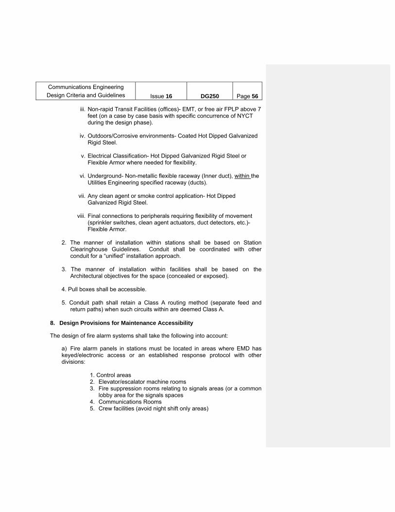
Communications Engineering
Design Criteria and Guidelines
Issue 16
DG250
Page 56
iii. Non-rapid Transit Facilities (offices)- EMT, or free air FPLP above 7 feet (on a case by case basis with specific concurrence of NYCT during the design phase).
iv. Outdoors/Corrosive environments- Coated Hot Dipped Galvanized
Rigid Steel.
v. Electrical Classification- Hot Dipped Galvanized Rigid Steel or Flexible Armor where needed for flexibility.
vi. Underground- Non-metallic flexible raceway (Inner duct), within the
Utilities Engineering specified raceway (ducts).
vii. Any clean agent or smoke control application- Hot Dipped Galvanized Rigid Steel.
viii. Final connections to peripherals requiring flexibility of movement
(sprinkler switches, clean agent actuators, duct detectors, etc.)- Flexible Armor.
2. The manner of installation within stations shall be based on Station
Clearinghouse Guidelines. Conduit shall be coordinated with other conduit for a “unified” installation approach.
3. The manner of installation within facilities shall be based on the
Architectural objectives for the space (concealed or exposed).
4. Pull boxes shall be accessible. 5. Conduit path shall retain a Class A routing method (separate feed and
return paths) when such circuits within are deemed Class A.
8. Design Provisions for Maintenance Accessibility The design of fire alarm systems shall take the following into account:
a) Fire alarm panels in stations must be located in areas where EMD has keyed/electronic access or an established response protocol with other divisions:
1. Control areas 2. Elevator/escalator machine rooms 3. Fire suppression rooms relating to signals areas (or a common
lobby area for the signals spaces 4. Communications Rooms 5. Crew facilities (avoid night shift only areas)

Communications Engineering
Design Criteria and Guidelines
Issue 16
DG250
Page 57
b) The drawings must indicate any areas that require special consideration including
1. Sidewall placement of smoke detectors in lieu of ceiling
placement for congested ceiling areas 2. Coordination with furniture and data equipment 3. Coordination of infra-red path for projected beam detectors and
access to mirror and control unit (a fixed ladder should be requested)
4. General notes must contain wording that the contractor must demonstrate the proposed placement of smoke detectors in the presence of EMD with consideration to other conduit and ductwork in the area of installation.
5. New technologies to address maintenance issues, such as air sampling systems, shall not be utilized without OSS and EMD concurrence.
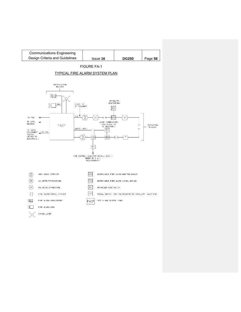
Communications Engineering
Design Criteria and Guidelines
Issue 16
DG250
Page 58
FIGURE FA-1
TYPICAL FIRE ALARM SYSTEM PLAN

Communications Engineering
Design Criteria and Guidelines
Issue 16
DG250
Page 59
H. SPEAKERPHONE SYSTEMS
There are 4 main categories of Speakerphone systems installed within the station environment:
1. Elevator cabs and landings shall be equipped with an ADA compliant speakerphone using Voice Over Internet Protocol (VOIP) for communications via the NYCT SACNS network. The speakerphone shall communicate to the Station Command Center desk at RCC and the station full time agent booth. In some cases and based on the scope of work, speakerphones (installed within a 1620 key locked enclosure) are provided for Fire Department use for customer entrapment communications (i.e., not two-way fire service communications). The system is typically POE connected to a local application node in coordination the data network design for the station.
2. Areas of Refuge (stations): The speakerphone shall be installed in areas of refuge for
emergency reporting only (Utilizing a single button speakerphone), utilizing Voice Over Internet Protocol (VOIP) for communications via the NYCT SACNS network. The speakerphone shall communicate to the Station Command Center desk at RCC, the station full time agent booth as well as the SECR (if provided).
3. Areas of Refuge (facilities). Non-sprinklered facilities shall be provided with an
ADA Area of Refuge system, comprised of speakerphones and a IP feature phone located in the lobby. The speakerphones, when required, will typically be located in each stairway on each floor specifically designated as ADA area of refuge. The speakerphones will be connected to the data switch in the local communications closet. The IP feature phone shall be provided at a location readily accessible to the fire department such as the first floor lobby with annunciation capability to a 24/7 location in the facility if the lobby area is not attended 24/7 (such as a property protection office). Where there is no 24/7 attended location on site the system shall dial out to either the Rail Control Center or the Bus Command Center.
The system (including associated LAN equipment) shall be connected to the emergency power source for the facility.
Where refuge areas are provided, cable survivability from fire shall be as per NFPA 72. In general, circuit pathways shall be routed via fire rated soffit areas and through fire rated vertical chases. Coordinate with Architectural Design.
4. Platforms, Passageways, and Control Areas shall be equipped with a two button
speakerphone commonly referred to as a Help Point (HP). The HP uses Voice Over Internet Protocol (VOIP) for communications via the NYCT SACNS network. Help Points shall be installed in conjunction with a full PSLAN installation or connected to an Access Node (AN) which is in turn connected to the SACNS network. An IP feature phone shall be placed in the full time agent booth to answer information calls. Help Points are to be placed such that a customer is never more than 200 feet from a

Communications Engineering
Design Criteria and Guidelines
Issue 16
DG250
Page 60
visible HP. Typically they will be placed approximately 150 feet from either end of a platform. Additional HP units will be placed on platforms when the view is obstructed by stairs or other structural items. In part time or unmanned control areas, two HP units shall be placed, one on the unpaid side and one on the paid side. In addition, an Access Node (AN) shall be placed in the control area. In stations that have new fire alarm systems with manual Pull Stations, HP locations shall be coordinated to be in close proximity to the Pull Station and any associated CCTV cameras.
A variant of this application entails the use a dedicated function speakerphone for AFAS gates (one per side) that are not within view of a full time Agent Booth. This speakerphone provides communication only to the Station Agent for purposes of remote opening of a gate for physically challenged customers. Where IP cameras are also provided for an ADA installation, the speakerphone shall be arranged to call up the associated camera on the booth IP feature phone when the dedicated function AFAS gate speakerphone is activated (similar to the way an elevator speakerphone is connected. See F.2.d.vii (CCTV System).
5. A speakerphone system can also be used at other locations (e.g., in yards – with
speakerphone units at gates and the feature phone at a guard booth). These speakerphones may be analog or VOIP (wired or wireless) units and are available for a variety of applications.
I. TRAIN DISPATCHING SYSTEM AND NO. 6 EMERGENCY LINE
The Train Dispatcher System (TDS), also referred as Line Speakers is a party-line intercom system providing half-duplex, two-way audio communications. TDS enables console operators at the Rail Command Center (RCC) to communicate with selected field consoles on a “party line” basis. It also enables field consoles to communicate with each other on the same “party line". If expansion of the system is required, (i.e. addition of field locations), the originally specified equipment shall be used to ensure full compatibility. See “TYPICAL TRAIN DISPATCHING SYSTEM (TDS) DIAGRAM.”
The number of TDS lines in each division is as follows: Division “A” – four (4) TDS lines: 1, 2, 3, and 4 Division “B1” – seven (7) TDS lines: 1, 2, 3, 4, 5, 7, and 8 Division “B2” – five (5) TDS lines: 1, 2, 3, 4, and 5 The No. 6 Emergency Line (6-Wire System) is a separate system that runs in parallel with the TDS equipment that provides constant communication between all operating divisions (MOW, RTO, DCE, STA, 65 Commercial St) and Police Department.
The Train Dispatching System and No. 6 Emergency Line consist of two groups of equipment as follows: 1. Rail Command Center Line Speakers Equipment:

Communications Engineering
Design Criteria and Guidelines
Issue 16
DG250
Page 61
Train Dispatching System: a. Trainmaster’s Console (CBDS workstation) equipped with GUI display for the
train dispatching functions and a separate control console dedicated to the No. 6 Emergency Line.
b. One Microphone and stand, with a preamplifier provided in the stand,
connecting to CBDS workstation to communicate with selected TDS lines on the GUI screen.
No. 6 Emergency Line:
a. One control console with gooseneck microphone Push-To-Talk Button, and loud speaker to provide an Alert Tone in conjunction with transmissions into the No. 6 Emergency Line.
Associated equipment cabinets are part of the PENTA system that houses Line cards, Matrix cards, and Console cards for interfacing TDS functions to CBDS workstations.
2. Field Console Equipment:
Field Console equipped with gooseneck microphone, Push-To-Talk button, and loud speaker, connected to the designated TDS Line trough audio bridges.
The No. 6 Emergency Line speakers equipped with loud speaker for monitoring only (however some locations may also be equipped with gooseneck microphone and Push-To-Talk button for making emergency announcement), connected to the designated 6-Wire system equipment.
Wall-mounted equipment cabinet is equipped with 4-way, 6-way, and/or 8-way audio bridge, populated with input/output modules as required, to connect field control consoles and No. 6 Emergency Line speakers
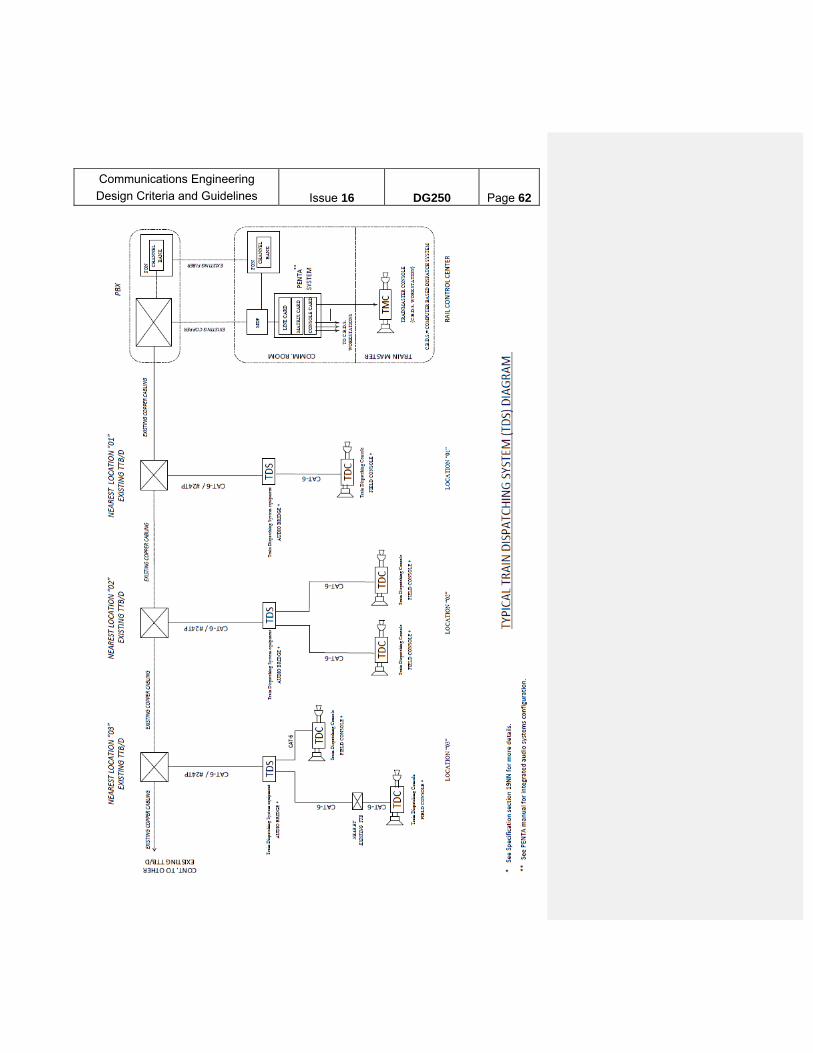
Communications Engineering
Design Criteria and Guidelines
Issue 16
DG250
Page 62

Communications Engineering
Design Criteria and Guidelines
Issue 16
DG250
Page 63
J. VARIOUS COMMUNICATIONS EQUIPMENT FOR FARE BOOTHS
1. The Emergency Booth Communications System (EBCS) with Mass Call and Speed Dial (MCSD) capability is a computerized system providing means for emergency communication between fare booths throughout the system and the Stations Command Center.
It is a modular system, allowing for expansion (i.e. addition of more fare
booths) in accordance with the original specification. Each fare booth shall include the following equipment:
Remote Processing Station (R.P.S.) Hand Alarm Switch Foot Alarm Switch Portable Panic Transmitter (P.P.T.) L.E.D. Display Unit Manuals and drawings for the system are available.
2. Each fare booth shall be equipped with a radio scanner. This unit continuously monitors RTO frequencies.
3. Each selling position of the fare booth shall be equipped with
intercommunications equipment to permit the agent to communicate with the public.
4. The full-time fare booth is also equipped with a remote monitoring panel
for the station’s fire alarm system, a dedicated IP feature phone (video phone) for use in answering in-coming calls from ADA speakerphones located in elevators, at elevator landings and other locations. These items are discussed in this DG in the paragraphs covering fire alarm systems, CCTV systems and ADA speakerphone systems respectively.
5. An emergency type telephone (ET) shall be installed outside each fare
booth.
6. Each fare booth shall be furnished with an induction loop system to assist the hearing impaired.
K. INTEGRATED TELEPHONE/ PAGING SYSTEM
1. Provide a telephone-accessible, programmable, loudspeaker paging system - integrated with the telephone system - as required. (Usually, this is not required at a passenger station; but when it is, it would be for a non-public facility of substantial size within a passenger station or terminal stations with a Dispatcher’s Office and crew quarters. Dispatcher’s Office shall be provided

Communications Engineering
Design Criteria and Guidelines
Issue 16
DG250
Page 64
with master paging intercom station). It shall be capable of providing announcements throughout the facility. Amplifiers and related equipment shall be rack-mounted in the Communications Room/closet(s).
2. Provide loudspeakers covering work areas, corridors, locker rooms, storage
rooms and other locations, as required by the user department.
3. The loudspeaker paging system shall be integrated with the telephone system (local switch) so that paging announcements may be made from designated telephone instruments using easy-to-remember codes (similar to extension numbers used to make intercom calls from the telephone).
4. The loudspeaker paging system shall have the capability to page by zones,
including all-call.
5. Follow the design guidelines of paragraph C. - TELEPHONE SYSTEMS / SETS.
L. SOUND-POWERED TELEPHONE SYSTEMS
I. FOR FDNY USE
1. The system shall permit FDNY personnel to communicate from station areas and/or tunnel locations to Siamese locations at street level via sound powered telephone instruments.
2. The conduit routing shall in general follow the routing of the standpipe
system. 3. This system shall continue to be installed as a back-up to the wireless
system. The wireless system provides radio communication for FDNY and other first responders from the subway.
II. FOR FAN PLANT MAINTENANCE
1. The system shall permit personnel responsible for maintaining fan plants to communicate with each other via sound powered telephone instruments to enable communication between the control room, associated electrical distribution room, fan chamber and damper bays.
a. For locations prone to flood and as coordinated with the user
department, utilize a sound-powered telephone system provided with signaling device and a permanently connected handset, all housed in an enclosure.
b. For all other locations and as coordinated with the user department,
the sound-powered telephone system shall be consistent of a plug-
Communications Engineering
Design Criteria and Guidelines
Issue 16
DG250
Page 65
in type jack housed in an enclosure. The system shall also be provided with plug-in type handset.
III. FOR PUMP MAINTENANCE
1. The system shall permit personnel responsible for maintaining pumps to
communicate with each other via sound powered telephone instruments to enable communication between the pump room, electrical distribution room, and the generator receptacle.
a. For locations prone to flood and as coordinated with the user
department, utilize a sound-powered telephone system provided with signaling device and a permanently connected handset, all housed in an enclosure.
b. For all other locations and as coordinated with the user department,
the sound-powered telephone system shall be consistent of a plug-in type jack housed in an enclosure. The system shall also be provided with plug-in type handset.
M. MISCELLANEOUS EQUIPMENT AND SYSTEMS:
I. CLOCKS, SYNCHRONIZATION AND RELATED ITEMS
1. Provide time indicating clocks and time synchronization of systems as required. Consider the use of PoE capable digital clocks. (Usually, Communications Engineering is not required to provide clocks for the public areas of a passenger station with exception to end of platform at certain terminal stations that do not have a Dispatchers’ Office within the confines of the track level, but they are required in certain non-public locations within the passenger station (Offices, crews Quarters, SECR, Signals CBTC and New Tech locations) Ruggedized clocks are required for extreme environments and outdoor platforms. Platform clocks cannot have red numbers. Power for ruggedized clocks may be run locally (not backed up from Communication Room). Coordinate with Electrical Design to provide 120 VAC and any related equipment.
2. Clocks and other equipment such as digitizers and recorders in certain
locations (e.g., dispatcher offices, towers, Signal rooms and relay rooms) require synchronization. If synchronization is required, the method of synchronizing the clock(s) must be shown on the contract drawings and/or defined in the contract specifications. Synchronization to the Authority’s clock signal is the preferred method. If this method is not possible, synchronization shall be made to the universal time signal using antenna and required module. GPS method of Synchronization should also be considered.

Communications Engineering
Design Criteria and Guidelines
Issue 16
DG250
Page 66
3. The type of clock (e.g., conventional circular analog clock, four digit digital, six digit digital IP clock) must be shown on the contract drawings and/or defined in the contract specifications. Synchronized, six digit (hours, minutes and seconds), digital clocks are required for certain RTO personnel for precise time indication. Non-synchronized, four digit (hours and minutes), digital clocks or analog clocks are usually specified for other locations.
4. Make provisions for KRONOS timekeeping units including cable and
conduit runs for power and data, as required. These units are installed by in-house forces at locations which have been prepared under the contract.
5. A local attendance recording and signaling system may be required at
certain locations. A typical system consists of a master clock, punch clocks with card racks/cards, secondary time clocks and synchronization modules and antenna. These systems are controlled by a master clock. They record attendance on a punch card unit (time clock), they synchronize the facility’s time indicating clocks, and they can provide audible indications to signal the beginning and end of a shift. They are frequently synchronized by a signal received from an antenna installed at the facility. GPS method of synchronization may also be used.
II. FIRE EXTINGUISHERS
1. Provide portable fire extinguishers as required in compliance with the International Fire Code, NFPA 10 and Office of System Safety Policy/Instruction 10.4.3.
6. Refer to Specification 19H- Portable Fire Extinguishers for acceptable
models
3. Dry chemical type fire extinguishers are provided in areas containing:
c. Fire hazards associated with rubbish, wood and plastic materials d. Fire hazards associated with flammable/combustible liquids e. The only acceptable ratings for CPM related projects are
10A:120BC (for general area protection and dedicated room protection) and 40A:240BC (bus depot fueling area)
4. Carbon dioxide type fire extinguishers are provided in areas for
dedicated protection of electrical/power service equipment, communications equipment and other areas containing sensitive electronic equipment. The only acceptable rating for CPM related projects is 20B:C
Communications Engineering
Design Criteria and Guidelines
Issue 16
DG250
Page 67
5. Dedicated protection fire extinguishers in Subways locations such as Signal Rooms, Substations and Communications Rooms shall be mounted without a cabinet
6. General area protection for industrial areas in shops shall be mounted
without a cabinet 7. Fire extinguishers in finished areas of facilities shall be semi-recessed
and the cabinet shall be selected in coordination with Architectural Design to address fire rating of cabinet (if required) and aesthetics
8. Fire extinguishers for general area protection shall be provided such
that the maximum travel distance to an extinguisher is 75 feet along the egress path. Dead ends in corridors, niches and closets are not acceptable locations
9. One wheeled dry chemical fire extinguisher is required for the bus
fueling area. The stored location will be adjacent to the exterior roll up door in a location coordinated with the Architectural discipline to avoid obstructions to bus movement and egress. Outdoor placement is not acceptable due to complications of snow and ice cover
III. INTERCOM SYSTEMS
For certain facilities, the user department may request an intercom system.
(Intercom systems were previously used at passenger stations to provide the means for the public to communicate with the full-time fare booth from certain locations in the station. Currently, ADA-compliant speakerphone systems are used. These are actually telephone systems. See paragraph H –SPEAKERPHONE SYSTEM.
Intercom units are generally categorized as master stations and staff stations.
The master station is installed at a central location. It communicates with multiple staff stations. Typically, staff stations are remotely located and are designed to call only one master station. Operation of a switch on the staff station (usually a pushbutton) signals the master station. The person at the master station responds by operating the switch that corresponds to the calling staff station, thereby permitting a conversation.
IV. PUMP ROOMS / DEEP WELLS
Provide an emergency type telephone with box and external ringer in each pump
room as per DG303 –– Pump rooms design guidelines.
V. COMMERCIAL DYNAMIC SIGNAGE
Communications Engineering
Design Criteria and Guidelines
Issue 16
DG250
Page 68
For system expansion projects, Communications data port/outlet shall be provided for each commercial dynamic signage within the station. The data port/outlet shall connect back to the NYCT TTB in the Verizon room. An additional conduit shall be provisioned between the Communications room and the TELCO room for future data connectivity of the dynamic signage over NYCT network.
VI. LCD BASED CUSTOMER INFORMATION DISPLAYS
There are two types of LCD based customer information displays being installed on NYCT property:
1. On-The-Go (OTG) is an interactive touch screen based kiosk (typically freestanding) that allows users to observe service status, and query information. It also displays commercial advertisements and public service announcements.
2. Service Advisory Information Display (SAID) is a non-interactive flat panel display
system (typically wall or ceiling mounted) that displays service status. Both OTG and SAID operate from 120VAC and require either an IP connection
(copper or FO) to the nearest Comm Room or a 4G cellular connection to the Verizon network.
Placement of OTG and SAID are done based on joint surveys including
Corporate Communications, Stations, System Safety, Program Coordination, MOW Engineering, Communications Engineering, and Advertising Partners (in the case of OTG). Locations should maximize passenger visibility, and not impede normal traffic flow or cause unsafe conditions.
Network connectivity should take advantage of existing infrastructure such as
PSLAN, or Transit Wireless or Verizon 4G coverage before constructing dedicated infrastructure.
There are no requirements for protected power for OTG and SAID. Coordinate
power feed with Electrical Engineering.
VII REMOTE EYEWASH ALARM Remote eyewash alarms may be required for very large facilities or locations
where additional alarm capability is needed beyond the local horn/strobe that is attached to an eyewash station. There are two general approaches:
1. Utilize the fire alarm system to monitor the eyewash flow switch to sound a supervisory alarm and dedicated horn/strobe at designated 24/7 areas within a facility. This is the preferred solution for locations within facilities.

Communications Engineering
Design Criteria and Guidelines
Issue 16
DG250
Page 69
2. Utilize a wireless radio solution. This is for locations in yards that are
remote from buildings.
N. DATA CABLING AND EQUIPMENT
1. Provide data/network equipment and cabling to connect various locations in the station with the communications room. Data/network equipment and fiber optic cable design guidelines can be found in DG 259. Coordinate with FO Network Designers.
2. Copper data cables shall be minimum rated CAT6 unshielded twisted pair for use
in high-speed data transmission.
3. For projects where cables are run in proximity of potential EMI interference, CAT6 shielded twisted pair cable should be used, with corresponding grounding of the shields and accompanying shielded jacks and patch panels.
4. When the distance between elevator or escalator machine room and the
communications room is over 200 feet (direct point-to-point) use one of the following options based of field conditions:
a) Use a media extender technology, such as Ethernet/IP over DSL circuit, to
the nearest data access site.
b) Use a media converter technology, over fiber, to the nearest data access site.
c) Cellular modem/leased service from wireless provider.
5. Cat 6 stranded conductor cable shall be utilized for Patch Panel connections
O. COMMUNICATIONS ROOM CONSIDERATIONS 1. Equipment cabinets for various Communications systems, and the UPS (power
plant) to provide backup power for these systems, are installed in the Communications Room.
2. Include load and backup duration for each Communications system (including
future) to determine UPS (power plant) requirements. 3. Cables for Telephone company (Telco) circuits should be terminated in a
separate room or closet. At locations where this is not possible, provisions should be made for a space that is out of view of the public. The Communications Room may not be used for Telco circuits. Furnish a 25 pair cable between the station Communications room and the Telco location. Terminate one end of the cable in
Communications Engineering
Design Criteria and Guidelines
Issue 16
DG250
Page 70
the Communications room TTB/TTBD and the other end on a NYCT provided 25 pair terminal block inside the Telco location. Provide a 3/4" plywood backboard in the Telco location to mount the 25 pair terminal block.
4. The contract drawings must show the types and locations of any equipment
cabinet to be installed in the Communications Room. 5. Equipment cabinets shall be mounted on 3.5” pre-molded concrete pad. Per
field conditions, concrete pad may be acceptable. 6. For system expansion projects, NYCT non-wireless Communications rooms and
NYCT wireless Communications rooms shall be protected by an Inergen system. 7. In addition to the main communications room, facilities will be provided with
additional secondary communication rooms or closets as required. 8. Network equipment maintained by TIS Security are not to be installed in
Communications Rooms controlled by EMD, and vice versa. Designer will coordinate with the responsible group for room and space allocation for equipment under Contract. If an exception is made for co-location of equipment, ensure a signed memo is obtained from both groups agreeing to this exception. Network Access Control (NAC) security device is pre-approved to be installed in Communications Rooms.
9. During the Master Plan phase of a project, the Designer shall develop a high level
design that includes cabinets, enclosures, and equipment. When reserving space for these communication equipment, the Designer shall submit the Communication Room Space Request to reserve space for communication equipment. The Master Plan sign-off shall be contingent on the following:
a. If space is approved then MOW clearinghouse will return an approved
submittal which will be included in the Master Plan by the DM. The CPM Design Manager, Designer, and MOW shall agree to the most appropriate resolution for mounting equipment.
b. If no space is available in the communication room, alternate space should be proposed by the MOW clearinghouse (i.e., new communication room proposed, cabinet/equipment on station platforms), in conjunction with DOS Stations, CPM Program Coordination and Communications Engineering.
c. If space outside of a communication room is proposed then the DM will
include this proposal as part of the project scope.
d. If equipment cannot be determined during the Master Plan stage, the DM shall clearly include the exception in the Master Plan to indicate risk for possible space issues during the design stage.
Communications Engineering
Design Criteria and Guidelines
Issue 16
DG250
Page 71
e. If any other engineering discipline requires the placement of equipment (i.e., HVAC, electrical panels) inside a communication room it is required to go thru the same process as outlined above during the Master Plan phase.
Follow guidelines for Communications Rooms and Communication System
Clearinghouse Procedure for all work in the Communication Room. P. Guidelines for Power Plant Power plant shall be used in all cases where communications room
power is not already backed up by battery system. This includes station communications rooms and facility buildings. Power plant serves to provide a clean DC and AC power source, and provide power backup in case of loss of power. The extent of time for back-up is determined by the user requirements for up-time and by the availability of generator back-up for the facility. For example, a building with generator back-up capability would only require a power plant with adequate battery reserve to last until the generator is fully operational (typically between 5 minutes and 15 minutes), while a station communications room would require a power plant with up to 4 hours of battery reserve to operate all networking equipment. Designer shall consider each facility along with its available power capabilities in determining power plant needs.
Power plant shall be connected directly to a main electric panel. Multiple
feeds may be needed to provide adequate power; feeds shall be balanced across different phases (for multiphase systems). Power plant shall be made up of rectification stage, battery stage, and inverter stage. Designer shall determine sizing of each based on the required loads and up-time. Contact Electrical Engineering design team for guidance.
All critical systems shall be connected to the power plant, backed up by
one (or more) strings of batteries. Designer shall request from Operations and User Department as to what systems would be considered critical and require backup. In general, any equipment in support of carrying Signals (ATS, CBTC, interlocking), SCADA (Power, Fan, Pump), voice (emergency telephone, radio), and PA/CIS traffic shall be considered critical. This will include all network equipment (which provides the infrastructure for carrying this traffic), telemetry equipment (which provides the environmental indication to trigger emergency shutdown), and cabinet air conditioners (which provides acceptable operating temperatures).
Designer shall produce power calculations to determine the total worst
case power consumption of all equipment (including air conditioners). Designer shall coordinate with Operations and User Department to determine the minimum up-time for each application, and use this

Communications Engineering
Design Criteria and Guidelines
Issue 16
DG250
Page 72
information to calculate the minimum number of battery strings required to support the necessary up-time.
Designer shall coordinate closely with Electrical Designer to ensure that
the total power available to the facility can accommodate the necessary loads, and spare breaker positions are available to service the communications system. Loads shall include all network and applications equipment, air conditioners, room lighting, room outlets, and any other ancillary devices connected to the room breaker panel.
To determine the total power plant capacity, Designer shall consider the
loads, power plant efficiency, and any other required de-rating due to environmental conditions. All power cables shall be specified to minimally meet NEC recommendations.
1. New Power Plant Due to various electronic modules of modern power plants, new power
plant installed in station communications rooms shall be in enclosed cabinets.
New power plant shall be configured with -48VDC rectifiers connected to
minimum one string of battery. The rectifiers shall be configured to support an N:1 protection such that if one rectifier module fails, the backup module would be able to switch into service. Battery disconnects shall be specified for each battery string to allow disconnecting individual battery string for maintenance purpose. Inverters shall be provided to support a clean 120VAC output. Fuse and breaker panels shall be provided for both -48VDC and 120VAC distribution. Size of fuse and breaker shall be determined based on required load.
Power plant shall include capability to shed both AC and DC loads. Load
shed shall occur for each individual load for a configurable uptime. Designer shall determine the size and length of cable to install from the
power plant to equipment cabinets. For projects where this information cannot be determined (e.g., an RFP project where type of equipment is not known), Designer shall include guidelines for Contractor bidding purposes; indicate in the drawing any assumption on maximum cable size, and cable distance.
Designer shall coordinate with Structural Designer to ensure that battery
weight per unit area does not exceed the maximum floor loading capability of the room.

Communications Engineering
Design Criteria and Guidelines
Issue 16
DG250
Page 73
All cables from power plant to equipment cabinet and from power plant to main breaker panel shall be installed in separate conduit. Power cables shall not be carried alongside data cables.
2. Augmenting Power Plants When a power plant exists in a facility, Designer shall determine the
additional load placed on the power plant. Designer shall coordinate with Operations Department to identify the current power plant loading, and its rated load. Designer shall determine whether or not additional rectifiers, battery strings, inverters, or an entirely new power plant is required to support the project’s anticipated load.
Designer shall coordinate with Electrical Designer to ensure that adding
power plant modules does not exceed the room’s total power capacity.
3. Power Plant Installation For new power plants, Designer shall have verified all space
requirements for power plant, and have received confirmation of space reservations prior to completion of final design. Designer shall support construction efforts to ensure that power plants are installed in the approved location or as subject to change by the Operations Department. Ensure that all aisle clearance requirements, conduit terminations, overhead cable tray and conduit clearances are according to design.
4. Power Plant Testing
Designer shall ensure that power plant pass all relevant environmental
and load tests. Ensure all disconnects are working properly, and all voltage levels are within range during both no-load and full-load testing.
5. Powering PSLAN Access Nodes from Power Plant
Designer shall provide a Load Center with sufficient 10 amp AC breakers to individually power each Access Node. The Load Center shall be wired to a single 25 amp AC breaker in the Power Plant. If the power requirement for the Access Nodes exceeds the capacity of the 25 amp breaker, additional breakers and Load Centers will be required.
Q. ADDITIONAL CABLING CRITERIA 1. Do not use cable with halogenated materials in the subway that could cause the
risk that toxic gas will be released by these materials in a fire and quickly reach a dangerously high concentration. NYCT Wire and Cable Specifications TC, RG and TO provide requirements for low smoke, low toxicity, zero halogen cables.
Communications Engineering
Design Criteria and Guidelines
Issue 16
DG250
Page 74
In general, all cable for Communications systems and equipment should comply with these Specifications.
Specifications TC, RG and TO provide requirements (respectively) for copper
Communications cables, coaxial cables, and optical cables. They do not, however, list every type of cable required for Communications equipment. It will not always be possible to find the type of cable required for a particular system in these Specifications. Some cables will be available only in a construction that uses halogenated materials. The Office of System Safety will permit the use of such cables and wires in the subway if they are installed in conduit continuously for their entire length.
For non-subway applications, it is generally recommended - but not required - to
use cables meeting the NYCT Wire and Cable Specifications. These Specifications allow us to standardize around certain constructions and they help to guarantee the cable’s quality, but there may be a substantial cost difference above comparable cables listed in a manufacturer’s catalog. Catalog cables meeting widely accepted standards in the industry (UL, ASTM, NFPA, etc.) may be acceptable in lieu of cables meeting the NYCT wire and Cable Specifications. Also see the master contract specifications for requirements and characteristics for certain types of cables.
2. Do not use existing Figure 8 cable to support new aerially run cables. Existing messenger may be used within certain constraints (see contract specifications). Figure 8 cable is no longer used. Run cables on messenger wire where aerial installation is required.
3. Cable runs on the Railroad should be designed to have minimum visual impact. Do not run cables across station mosaic tiles. Proposed cable runs must be approved by Program Coordination.
4. Generally, communications cables are 22 AWG telephone cable from the Communications Room to feed rooms and/or devices. Fire Protection Sound-Powered Telephone system shall use 19AWG quad cable. See paragraph A -TELEPHONE CABLING, for additional criteria relating to cabling.
5. In yards, cables designed for direct burial may be used. If EMI (electromagnetic interference) is a concern, cable may be installed in buried steel conduit encased in concrete. (Use of wireless means of communication must be considered as an alternative to direct cable burial as determined by such factors as cost and maintainability)
R. SAMPLE CALCULATIONS 1. SAMPLE CALCULATION FOR MESSENGER bracket spacing The following cables are to be run on a new single messenger:
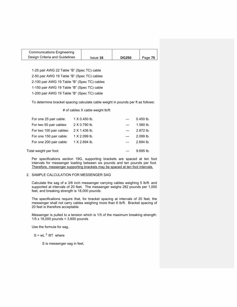
Communications Engineering
Design Criteria and Guidelines
Issue 16
DG250
Page 75
1-25 pair AWG 22 Table “B” (Spec TC) cable
2-50 pair AWG 19 Table “B” (Spec TC) cables
2-100 pair AWG 19 Table “B” (Spec TC) cables
1-150 pair AWG 19 Table “B” (Spec TC) cable
1-200 pair AWG 19 Table “B” (Spec TC) cable
To determine bracket spacing calculate cable weight in pounds per ft as follows: # of cables X cable weight lb/ft:
For one 25 pair cable: 1 X 0.450 lb. --- 0.450 lb.
For two 50 pair cables: 2 X 0.790 lb. --- 1.580 lb.
For two 100 pair cables: 2 X 1.436 lb. --- 2.872 lb.
For one 150 pair cable: 1 X 2.099 lb. --- 2.099 lb.
For one 200 pair cable: 1 X 2.694 lb. --- 2.694 lb.
Total weight per foot: --- 9.695 lb. Per specifications section 19G, supporting brackets are spaced at ten foot
intervals for messenger loading between six pounds and ten pounds per foot. Therefore, messenger supporting brackets may be spaced at ten foot intervals.
2. SAMPLE CALCULATION FOR MESSENGER SAG Calculate the sag of a 3/8 inch messenger carrying cables weighing 5 lb/ft. and
supported at intervals of 20 feet. The messenger weighs 282 pounds per 1,000 feet, and breaking strength is 18,000 pounds.
The specifications require that, for bracket spacing at intervals of 20 feet, the
messenger shall not carry cables weighing more than 6 lb/ft. Bracket spacing of 20 feet is therefore acceptable.
Messenger is pulled to a tension which is 1/5 of the maximum breaking strength:
1/5 x 18,000 pounds = 3,600 pounds Use the formula for sag, S = wL 2 /8T where S is messenger sag in feet,

Communications Engineering
Design Criteria and Guidelines
Issue 16
DG250
Page 76
w is the cable weight density (plus messenger weight density) in pounds per foot,
L is the length of the span between support brackets, and T is the tension in the messenger: S = (5.28 lb./ ft )x (20 ft)2/ (8 x 3,600 pounds) = 0.0733 ft = 0.0733 ft x 12 in/ft = 0.88 inches. The sag will be 0.88 inches for the given cable weight and bracket spacing. 3. SAMPLE CALCULATION FOR RACEWAY FILL Determine if the Wiremold Company’s surface metal raceway, catalog number
2000, may be used for 1-25 pair AWG no. 22 cable, and 2 quad AWG no. 22 cables (tables “E” and “I” of specification TC):
Cable cross sectional areas: For one 25 pair cable: 1 X 0.1886 in2 --- 0.1886 in2 For two quads (no. 22): 2 X 0.0177 in2 --- 0.0354 in2 Total cable area: --- 0.2240 in2
Check for installation in Wiremold Company surface metal raceway, catalog
number 2000: Interior cross sectional area of raceway: --- 0.80 in2 Available cross sectional area (based on 40% fill): --- 0.32 in2 The raceway’s available cross sectional area is greater than the total area
required by the cables: Wiremold catalog number 2000 may be used for this application.
Note: Cables are placed in this type of raceway - not pulled through. For
situations requiring cables to be pulled, check for sufficient space around the perimeter of the cable bundle (distance to the interior surface of the raceway) in addition to checking fill requirement.

Communications Engineering
Design Criteria and Guidelines
Issue 16
DG250
Page 77
S. Communication Design Contract Requirement Page 1 of 3
Oth
ers/
S
peci
fy
- - -
EB
CS
an
d
Inte
rcom
fo
r to
ken
boo
ths.
E
A f
or
elev
ated
st
atio
ns
(11)
Clo
cks/
C
lock
s S
ys/
Sys
tem
C
lock
s
-/-/
-
-/-/
-
-/-/
-
-/-/
(10)
FA
/FX
-/-
-/X
X/X
X/X
(9)
CC
TV
- - - X
(8)
Se
curit
y
- - - -
(7)
TD
S
- - - -
(6)
PA
/ P
age
-/-
-/-
-/-
X/-
(5)
Tel
/Tel
. S
ys
-/-
X
/-
X/-
X/-
(4)
EA
- - -- -
(3)
TT
B
X
X
X
X
(2)
Tel
. C
able
X
X
X
X
(1)
Dat
a
- X - X
Job
De
scrip
tion
/ R
equi
red
Eq
uip.
Fu
rnis
h an
d in
stal
l 100
to
150
pr. c
abl
e w
ithin
co
ntra
ct li
mits
. Ter
min
ate
at e
ach
sta
tion.
Run
25
pr.
fro
m s
tatio
n T
TB
to
toke
n b
ooth
.
Fu
rnis
h an
d in
stal
l 12
pr.
cabl
e fr
om n
ear
est
exis
ting
TT
B t
o ne
w T
TB
in
Pum
p R
oom
/Fan
C
ham
ber
to fe
ed
new
te
leph
one
s. P
rovi
de f
ire
extin
gui
sher
.
Fu
rnis
h an
d in
stal
l 12
pr.
cabl
e fr
om n
ear
est
exis
ting
TT
B t
o a
new
T
TB
in E
DR
/ Sig
nal
R
oom
. Pro
vide
new
te
leph
one
s a
nd f
ire
extin
gui
sher
in E
DR
.
Fu
rnis
h an
d in
stal
l new
P
A s
yste
m w
ith r
equi
red
cont
rols
. .P
rovi
de
new
25
pr.
#22
AW
G c
able
to
toke
n b
ooth
. R
elo
cate
all
com
mu
nica
tion
equi
pmen
t in
new
C
omm
unic
atio
n R
oom
. P
rovi
de C
CT
V if
re
qui
red.
Pro
vid
e ne
w
com
mu
nica
tion
equi
pmen
t in
toke
n ag
ent
boot
h in
clu
ding
tok
en
agen
t bo
oth
inte
rco
m
and
cust
omer
ass
ista
nce
in
terc
om if
req
uire
d.
Inst
all t
elep
hon
e a
nd f
ire
alar
m/e
xtin
guis
her
s in
ne
w r
oom
s a
s re
quire
d.
Co
ntra
ct
Ca
tego
ry
Mai
nlin
e T
elep
hon
e
Ca
ble
Mod
Pu
mp
R
oom
/Fan
C
ham
ber
R
eha
b
Tun
nel
Ligh
ting
C
ont
ract
/
Sig
nal
Mo
d
Sta
tion
Re
hab
C
ont
ract
s
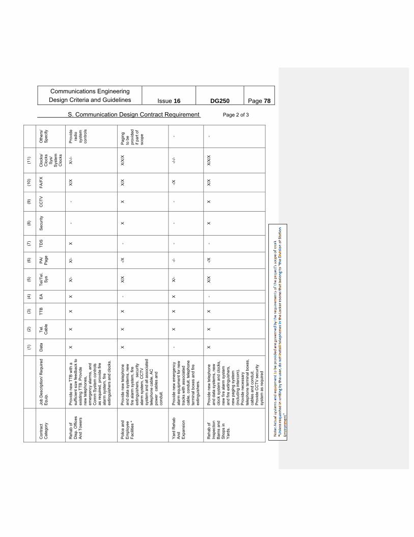
Communications Engineering
Design Criteria and Guidelines
Issue 16
DG250
Page 78
S. Communication Design Contract Requirement Page 2 of 3
Oth
ers
/ S
pec
ify
Pro
vide
ra
dio
syst
em
cont
rols
Pag
ing
to
be
p
rovi
ded
if
par
t of
scop
e - -
(11
)
Clo
cks/
C
lock
s S
ys/
Sys
tem
C
lock
s
X/-
/-
X/X
/X
-/-/
-
X/X
/X
(10)
FA
/FX
X/X
X/X
-/X
X/X
(9)
CC
TV
- X - X
(8)
Sec
urity
- X - X
(7)
TD
S
X - - -
(6)
PA
/ P
age
X/-
-/X
-/-
-/X
(5)
Tel
/Tel
. S
ys
X/-
X/X
X/-
X/X
(4)
EA
X - X -
(3)
TT
B
X
X
X
X
(2)
Tel
. C
able
X
X
X
X
(1)
Dat
a
X
X - X
Job
Des
crip
tion/
Re
quire
d E
qui
p.
Pro
vid
e ne
w T
TB
with
a
suffi
cien
t si
ze fe
edb
ack
to
exis
ting
TT
B. P
rovi
de
new
tele
pho
nes,
em
erg
ency
ala
rms,
and
Co
mm
Sys
tem
con
tro
ls
as r
equ
ired
, pro
vid
e fir
e al
arm
sys
tem
, fire
ex
tingu
ishe
rs a
nd c
lock
s.
Pro
vid
e ne
w te
leph
one
an
d d
ata
syst
em
s, n
ew
fir
e al
arm
sys
tem
, fire
ex
tingu
ishe
rs,
secu
rity
al
arm
sys
tem
, CC
TV
sy
stem
and
all
ass
ocia
ted
te
leph
one
cab
le, A
C
pow
er
cab
les
and
cond
uit.
Pro
vid
e ne
w e
mer
gen
cy
alar
m e
quip
me
nt fo
r ne
w
tra
cks
with
ass
ocia
ted
ca
ble,
con
dui
t, te
leph
one
term
inal
box
es a
nd
fire
extin
guis
hers
.
Pro
vid
e ne
w te
leph
one
an
d d
ata
syst
em
s, n
ew
cl
ock
sys
tem
and
clo
cks,
ne
w fi
re a
larm
sys
tem
an
d fi
re e
xtin
guis
hers
, ne
w p
agin
g sy
stem
(in
clu
ding
inte
rcom
).
Pro
vid
e ne
cess
ary
tele
pho
ne t
erm
inal
box
es,
cabl
es a
nd
cond
uit.
Pro
vid
e C
CT
V s
ecu
rity
syst
em a
s re
quire
d
Co
ntr
act
C
ateg
ory
Reh
ab o
f
Dis
p. O
ffic
es
And
Tow
ers
Pol
ice
and
E
mpl
oye
e F
acili
ties
*
Yar
d R
ehab
A
nd
Exp
ans
ion
Reh
ab o
f
Insp
ectio
n
Bar
ns
and
S
hops
in
Yar
ds.
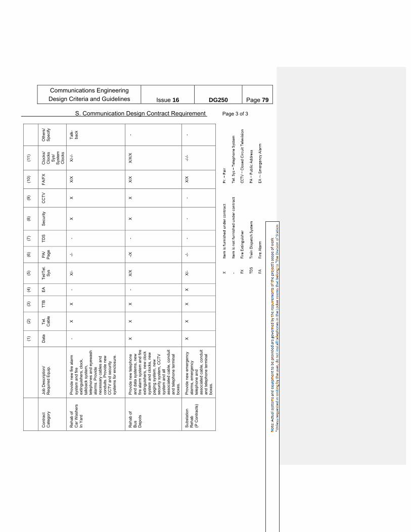
Communications Engineering
Design Criteria and Guidelines
Issue 16
DG250
Page 79
S. Communication Design Contract Requirement Page 3 of 3
Oth
ers/
S
peci
fy
Tal
k-ba
ck
- -
(11
)
Clo
cks/
C
lock
s S
ys/
Sys
tem
C
lock
s
X/-
/-
X/X
/X
-/-/
-
(10)
FA
/FX
X/X
X/X
X/X
(9)
CC
TV
X
X -
(8)
Se
curit
y
X
X -
(7)
TD
S
- - -
(6)
PA
/ P
age
-/-
-/X
-/-
(5)
Tel
/Tel
. S
ys
X/-
X/X
X/-
(4)
EA
- - X
(3)
TT
B
X
X
X
(2)
Tel
. C
ab
le
X
X
X
(1)
Dat
a
- X
X
Job
Des
crip
tion/
R
equ
ired
Equ
ip.
Pro
vid
e ne
w f
ire a
larm
sy
stem
and
fire
ex
tingu
ishe
rs, c
lock
, ta
lkb
ack
syst
em,
tele
pho
nes
and
eyew
ash
al
arm
s. P
rovi
de
nece
ssar
y ca
ble
s a
nd
cond
uits
. P
rovi
de
new
C
CT
V a
nd
secu
rity
syst
ems
for
encl
osu
re.
Pro
vid
e ne
w te
leph
one
an
d d
ata
syst
em
s, n
ew
fir
e al
arm
sys
tem
and
fire
ex
tingu
ishe
rs, n
ew
clo
ck
syst
em a
nd c
lock
s, n
ew
pag
ing
syst
em
, ne
w
secu
rity
sys
tem
, CC
TV
sy
stem
and
all
asso
cia
ted
cab
le, c
ond
uit
and
tele
pho
ne te
rmin
al
boxe
s.
Pro
vid
e ne
w e
mer
gen
cy
alar
ms,
em
erge
ncy
te
leph
one
and
as
soci
ate
d c
able
, con
dui
t an
d te
lep
hone
term
ina
l bo
xes.
Co
ntr
act
C
ateg
ory
Reh
ab o
f
Car
Wa
sher
s
In Y
ard
Reh
ab o
f B
us
D
epot
s
Su
bsta
tion
Reh
ab
(P C
ont
ract
s)

Communications Engineering
Design Criteria and Guidelines
Issue 16
DG250
Page 80
PART TWO: WIRELESS COMMUNICATIONS and SYSTEMS
I. Introduction
The demand for wireless systems for NYCT has dramatically increased, since a number of projects have contemplated the use of wireless for Voice, Data, and Video applications. The first radio system for NYCT was designed to provide reliable voice radio communications along the right-of-way for Rapid Transit Operations (RTO) and the Police. Other systems are now being built, using various mixes of Wireless, F.O. and copper based networks for not only voice, but also for data and video applications. The Department of Buses (DOB) has its own radio system which provides coverage throughout the city and permits communications with buses and other vehicles. This is being updated to a digital radio system to include voice, text and location related features. Also buses use cellular modems for Fare Payment System (FPS). In addition all new buses have an in bus vehicular LAN (IVN – Intelligent Vehicular Network) that operates in depots to download vehicle maintenance information. There are video cameras on buses that record activity, which can be downloaded in depot, as required. NYCT also has point-to-point microwave systems, local/in-building systems as well as WiFi and wireless Help Points (HP). 800MHz Digital radio is expected to replace current T-band radios used by EMD / maintenance used by DoS and operational radios for SIR. Various command centers have been designed to provide the facilities for operators at these locations to communicate via radio with the personnel and locations under their department’s jurisdiction.
II. Design Requirements – General For Wireless Systems designed for NYCT, regardless of it use for Voice or Data, the most important consideration in the design is to secure an FCC license in the appropriate frequency band. The frequency spectrum may be in the VHF, UHF, 4.9 GHz, SHF or EHF bands, either licensed, shared, subleased or unlicensed. Early consultation with CPM’s Wireless Principal Engineer is necessary in the design process. [Obtaining licensed spectrum takes considerable time and is not free. Unlicensed bands are more popular, but could be subject to increased noise level and interference]. Also as a general guideline NYCT discourages the use of unlicensed 2.4 GHz and 5.8 GHz bands due to its widespread usage by public that can have interference / security concerns. However, there are several other unlicensed bands that are not popular but useful, which can be considered for use such as the ISM 900MHz, UNII-1, 2 and 3 bands in the 5 GHz range. With good security measures in the radio links these could be invaluable since they offer broadband capability which is not available in the licensed bands. Security of all digital radio links are generally excellent, often superior to security schemes used in wired IP networks.
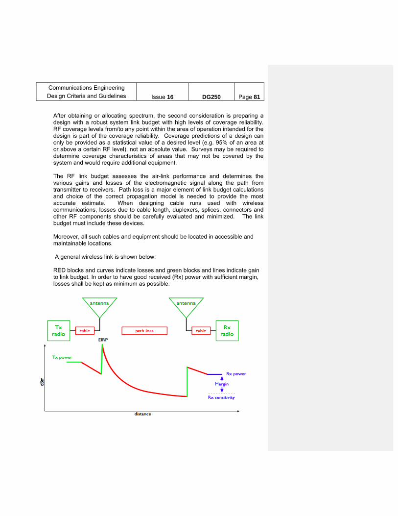
Communications Engineering
Design Criteria and Guidelines
Issue 16
DG250
Page 81
After obtaining or allocating spectrum, the second consideration is preparing a design with a robust system link budget with high levels of coverage reliability. RF coverage levels from/to any point within the area of operation intended for the design is part of the coverage reliability. Coverage predictions of a design can only be provided as a statistical value of a desired level (e.g. 95% of an area at or above a certain RF level), not an absolute value. Surveys may be required to determine coverage characteristics of areas that may not be covered by the system and would require additional equipment.
The RF link budget assesses the air-link performance and determines the various gains and losses of the electromagnetic signal along the path from transmitter to receivers. Path loss is a major element of link budget calculations and choice of the correct propagation model is needed to provide the most accurate estimate. When designing cable runs used with wireless communications, losses due to cable length, duplexers, splices, connectors and other RF components should be carefully evaluated and minimized. The link budget must include these devices.
Moreover, all such cables and equipment should be located in accessible and maintainable locations. A general wireless link is shown below: RED blocks and curves indicate losses and green blocks and lines indicate gain to link budget. In order to have good received (Rx) power with sufficient margin, losses shall be kept as minimum as possible.

Communications Engineering
Design Criteria and Guidelines
Issue 16
DG250
Page 82
In addition, provisions must be made to insure that any new wireless system will neither create interferences to existing systems, nor be affected by current systems.
For example, radiating antenna cable must be installed at a minimum of 12 inches from any metallic objects that may adversely affect it as well as be unobstructed.
The fluorescent lamps used in the subway tunnels may potentially affect Wireless systems; specification Section 19MB – Radio Interference Testing for Lamps - needs to be part of any wireless contracts involving tunnels and their lighting. In general, it is recommended that LED based lighting system be used since they do not have this interference problem but if fluorescent lighting is used, then its ballast shall have a Class B rating for Consumer Use as this class of device contributes less or no interference to wireless devices.
Additionally, new installations of any type should not create interference with existing radiating antenna cables. Caution must be exercised by other contracts not to obstruct any antenna path proposed or already in use.
PIM – Passive Inter Modulation is a major concern for “in-building” systems. This noise produced by metal-to-metal junction such as the tungsten filament to metal contact incandescent bulb, tends to raise the noise floor in cellular systems. Therefore, any bulb or LED fixtures should not be placed within 3 feet of cellular antennas.
The master contract specifications should include clauses protecting the wireless performance needed for the project. Selection of Portable (handheld) and mobile (car-borne) radios must address the following qualifications: ease of use features (e.g. PTT and/or hands-free), operable in the assigned frequencies, be rugged and reliable, and include battery chargers in required quantities. Coordination with the user, Electronic Maintenance Divisions, and Subways or Bus Engineering is required prior to selecting these devices. In every case it is important to note that the user device has a lower transmit power than the radio infrastructure and therefore all modern radio systems are “uplink limited”. It is critical that this uplink is referenced as the “worst case” to define performance. Closing niches in the underground subway system can seriously impact passenger safety by disrupting radio communications in the affected areas. Any design requiring below ground niche closure must be reviewed by CPM-Communications Engineering. Modifications to the existing radio infrastructure, and additional antenna cabling, and additional radio equipment may be required to mitigate the effects of the niche closure. During the Master Plan stage, Communications Engineering must perform an impact analysis and develop an appropriate scope. All required changes to the radio system must be

Communications Engineering
Design Criteria and Guidelines
Issue 16
DG250
Page 83
implemented prior to the commencement of any activity implementing such as niche closures.
Note: The selection of frequencies for NYCT use in any wireless system continues to be a design challenge. Coordination of all frequency design needs to be centrally coordinated. Any new frequency request or use of any wireless devices should be referred to Communications Engineering for compliance with FCC rules. Any sensitive system, designed on public frequency bands, should consider any potential threat. All spectrum use and allocation shall be done during the planning phase of a project as spectrum allocation depends, to a great extent, on factors outside NYCT Control. Applications for spectrum are prepared by Communications Engineering’s Principal Engineer for Wireless and submitted to the appropriate FCC frequency coordination entities. Moreover, all wireless systems shall abide by the license parameters for the frequency channels in use. III. Design Requirements and Guidelines – Specific Systems
The design requirements and guidelines for Wireless Systems are dependent on the nature of the wireless application, e.g. voice, data, video or carrier (commercial). For Voice Radio systems, the requirement will primarily focus on area coverage probability, signal link budget, and clarity of voice reception (DAQ) on the uplink and downlink channels. For Data or Stream radio systems, the requirements focus on signal link budget exists but more emphasis is placed on the throughput of the system, time delay and accurate delivery of error free (BER/FER) messages sent to the end unit. In addition to DAQ, the FER must be specified. Note that unlike DAQ, the FER is a quantitative evaluation and is therefore not “subjective”
A. SUBWAY UHF/ VHF WIRELESS VOICE COMMUNICATIONS
The existing NYCT subway radio system were designed to provide voice communications for RTO, and NYPD/Transit Bureau personnel using handheld radios and mobile (car-borne) units covering the whole NYCT infrastructure, including outdoor and underground indoor tracks. A dedicated UHF two channel repeater system is installed in the underground subway for use by FDNY. 1. UHF/VHF radio Infrastructure coverage principles:
Ensure coverage of the subway right-of-way by selecting primarily high-quality, low-loss, radiating antenna cables that meet the cable specifications for use in the subway. Underground tracks and stations shall have a minimum of two cables to provide radio coverage (uplink and downlink);
Next, ensure coverage of all mezzanines, passageways, and other passengers areas within a station, by ways of cable splitters branching off from the cable;
Communications Engineering
Design Criteria and Guidelines
Issue 16
DG250
Page 84
To provide coverage continuity with less signal loss, use non-radiating cable and discrete antennas or a distributed antenna system;
Use multiband discrete antennas formerly known as “Firecracker” antennas to provide coverage for smaller areas.
At elevated and open-cut portions of the railway tracks, use standard land
mobile radio type antennas to provide radio coverage which may be omnidirection or directional.
3. Selection, amplification and transmission of the signals
Radio base stations exist throughout the railway infrastructure. The number of locations of the Base stations should be determined such that they compensate the link cable loss (link budget) and provide coverage to the farthest point. Base station must be located in communications room and remains the center to feed the radiating antenna system.
The Subways Radio System permits communication between train
operators and the command center. To provide access to the system from a dispatcher’s office or tower, add a Tone Remote Control Console (TRCC). Local Dispatcher Remote Control Units (LDRCUs) have been discontinued; TRCCs have replaced these devices.
RTO radio system is accessible from the Rail Control Center (RCC) and
the Back-up Control Center (BCC) via a Computer Based Dispatch Console System
Some master towers use a small Computer Based Dispatch System to
access RTO base stations.
For NYPD and EMS use a channelized bidirectional signal booster system is installed in the underground subway. NYPD and EMS users in the elevated and outdoor areas of the subway utilize the respective NYPD and EMS outdoor systems that are not part of NYCT’s network. FDNY firefighters have access to a dedicated fireground UHF repeater network for underground areas.
3. Current system performance requirements
Coverage for UHF/VHF radio systems throughout all passenger areas of the facility, tunnels, and on moving trains, shall meet the following criteria:
1. Downlink: A minimum Signal Strength -95dBm and 20dB SINAD measured using a portable radio worn at hip with a coil-cord speaker microphone and standard helical whip antenna. 2. Uplink: Signal Strength from portable radios transmitting from a moving train, worn at the hip with a coil-cord speaker microphone using a standard helical whip

Communications Engineering
Design Criteria and Guidelines
Issue 16
DG250
Page 85
antenna. Power levels, measured at the inputs to all Communication Room amplifiers shall be at least +20dB above the noise floor of the equipment or system on frequency/channel but not less than –95 dBm. 3. Use 5W portable radios for VHF, and 1W radios for UHF. 4. On both VHF and UHF, the minimum acceptable Delivered Audio Quality (DAQ) is 3.4 for portable to portable, and portable to dispatcher communication for each uplink and downlink channel. 5. Provide 95% coverage. 6. Provide 95% reliability.
The system shall provide seamless hand-off to and from all adjacent
systems in connecting passageways, tunnels and on moving trains.
The leakage* allowance in the street shall be less than -100dBm on all VHF and UHF carriers.
The Battery backup for the standard fully functional two-channel VHF radio
cabinet (VRC) including all components shall be designed for an operating period of 35 hours under the following operating duty cycles:
o The first 6 hours of operation is 50% transmit and 50% standby o The next 23 hours of operation is 100% standby o The last 6 hours of operation is 50% transmit and 50% standby
For equipment layouts in Communications Room cabinets refer to the Communications Room Specification (19CR).
Environmental considerations, refer to specification section 19Z.
B. VIDEO-DATA WIRELESS SYSTEMS The design of these systems will focus more on the throughput, bandwidth, performance and reliability parameters of the data and video streams accuracy transmitted. Transmission of video is possible only on broadband wireless systems. Narrow band (12.5 and 25 KHz) systems cannot support video. B-1. CBTC SYSTEMS- AIR GAP INTERFACE: TRAIN-WAYSIDE Wireless links are a significant ingredient of CBTC VITAL data messaging networks used by NYCT Signals and Systems. They provide a link between the fixed railway wayside infrastructure and the moving vehicle on the track. These
* Leakage – the amount of unintentional radio signal that radiates from the underground that can be measured in street areas or outdoor areas.
Communications Engineering
Design Criteria and Guidelines
Issue 16
DG250
Page 86
systems have a rather complex system design which goes well beyond the scope of these guidelines: a short overview of what the air gap interface design will need to consider is given below. Cell design and radio cycle (TDMA) will need to be specified.
The design needs to consider first the reliability level requested of this critical systems, both on the data network and the wireless links. (MTBF% value: 99.999…).
The second most critical design component is the choice of the appropriate frequency band (SHF), and from it which frequency are going to be used per cell and the frequency reuse scheme between all the cells of the line. NYCT has adopted the 2.4GHz ISM band for CBTC operations using proprietary modulation schemes.
Next, the design will address the details of the channelization schema and the proper application of DSSS and FHSS technology to mitigate interferences and insure reliability goals.
The DSSS modulator may need to use 64 Kbps DQPSK modulation.
Four 127 chip sequences may be chosen.
The BER should be chosen to at least 10-6, hence a Frame Error Rate of 10-3.
More than 50dB rejection should be ensured between two non-adjacent channels
The link budget shall be derived for the uplink and downlink channel, train to wayside transmission and vice versa. Loss by train blockage shall be evaluated.
Coverage guarantee is specific to each NYCT line configuration, where the nature of the line elements (cut over, underground, elevated, etc.) will impose the main constraints on the wireless design.
Power availability plans and link budgets requirements will drive the locations determination of the main base cells and associated antennas on the wayside.
The same requirements apply to locations of antennas on the train cars.
B-2. NYCT YARD WIRELESS VIDEO SURVEILLANCE New York City Transit has deployed IP based CCTV cameras routed through a wireless network in rail yards. The wireless network consists of 5 GHz point to multipoint radio links aggregated at a key point in the train yard. The aggregated video traffic is then backhauled on a point-to-point 60 GHz link towards the
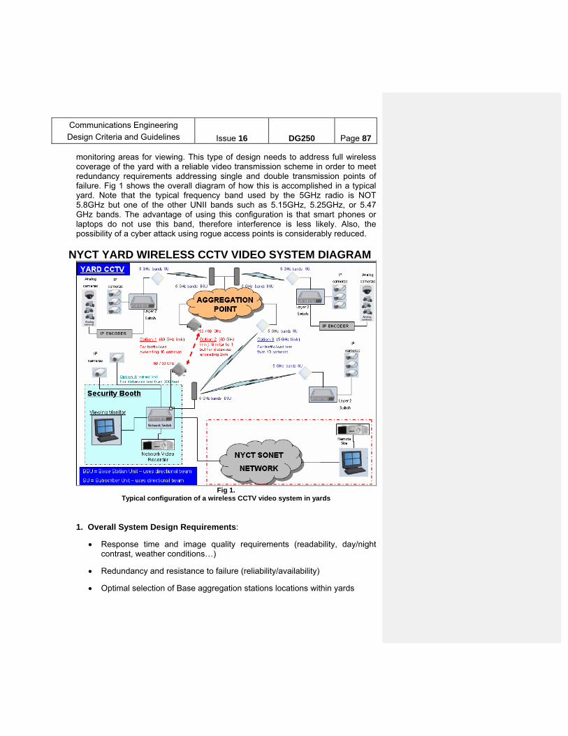
Communications Engineering
Design Criteria and Guidelines
Issue 16
DG250
Page 87
monitoring areas for viewing. This type of design needs to address full wireless coverage of the yard with a reliable video transmission scheme in order to meet redundancy requirements addressing single and double transmission points of failure. Fig 1 shows the overall diagram of how this is accomplished in a typical yard. Note that the typical frequency band used by the 5GHz radio is NOT 5.8GHz but one of the other UNII bands such as 5.15GHz, 5.25GHz, or 5.47 GHz bands. The advantage of using this configuration is that smart phones or laptops do not use this band, therefore interference is less likely. Also, the possibility of a cyber attack using rogue access points is considerably reduced.
NYCT YARD WIRELESS CCTV VIDEO SYSTEM DIAGRAM
Fig 1.
Typical configuration of a wireless CCTV video system in yards
1. Overall System Design Requirements:
Response time and image quality requirements (readability, day/night contrast, weather conditions…)
Redundancy and resistance to failure (reliability/availability)
Optimal selection of Base aggregation stations locations within yards
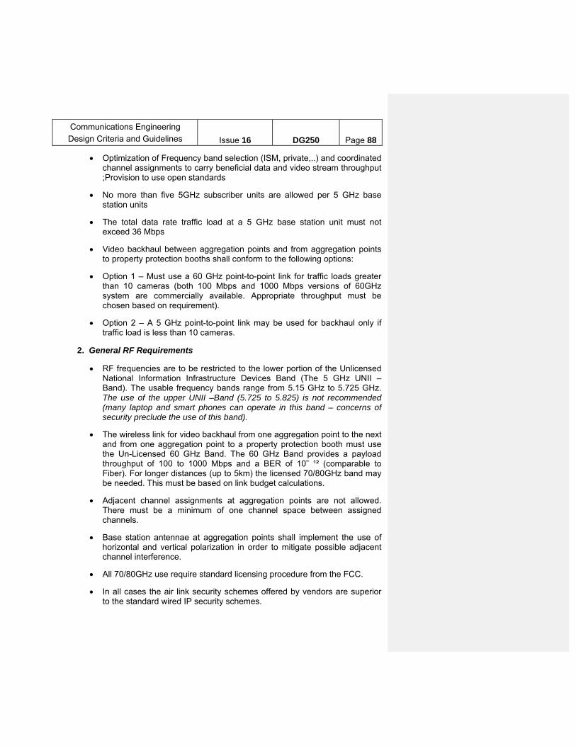
Communications Engineering
Design Criteria and Guidelines
Issue 16
DG250
Page 88
Optimization of Frequency band selection (ISM, private,..) and coordinated channel assignments to carry beneficial data and video stream throughput ;Provision to use open standards
No more than five 5GHz subscriber units are allowed per 5 GHz base station units
The total data rate traffic load at a 5 GHz base station unit must not exceed 36 Mbps
Video backhaul between aggregation points and from aggregation points to property protection booths shall conform to the following options:
Option 1 – Must use a 60 GHz point-to-point link for traffic loads greater than 10 cameras (both 100 Mbps and 1000 Mbps versions of 60GHz system are commercially available. Appropriate throughput must be chosen based on requirement).
Option 2 – A 5 GHz point-to-point link may be used for backhaul only if traffic load is less than 10 cameras.
2. General RF Requirements
RF frequencies are to be restricted to the lower portion of the Unlicensed National Information Infrastructure Devices Band (The 5 GHz UNII – Band). The usable frequency bands range from 5.15 GHz to 5.725 GHz. The use of the upper UNII –Band (5.725 to 5.825) is not recommended (many laptop and smart phones can operate in this band – concerns of security preclude the use of this band).
The wireless link for video backhaul from one aggregation point to the next and from one aggregation point to a property protection booth must use the Un-Licensed 60 GHz Band. The 60 GHz Band provides a payload throughput of 100 to 1000 Mbps and a BER of 10⎯ ¹² (comparable to Fiber). For longer distances (up to 5km) the licensed 70/80GHz band may be needed. This must be based on link budget calculations.
Adjacent channel assignments at aggregation points are not allowed. There must be a minimum of one channel space between assigned channels.
Base station antennae at aggregation points shall implement the use of horizontal and vertical polarization in order to mitigate possible adjacent channel interference.
All 70/80GHz use require standard licensing procedure from the FCC.
In all cases the air link security schemes offered by vendors are superior to the standard wired IP security schemes.
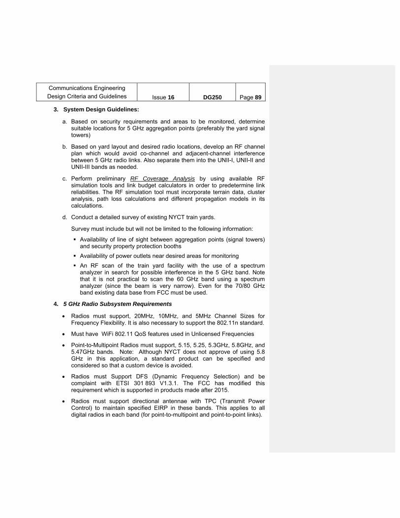
Communications Engineering
Design Criteria and Guidelines
Issue 16
DG250
Page 89
3. System Design Guidelines:
a. Based on security requirements and areas to be monitored, determine suitable locations for 5 GHz aggregation points (preferably the yard signal towers)
b. Based on yard layout and desired radio locations, develop an RF channel plan which would avoid co-channel and adjacent-channel interference between 5 GHz radio links. Also separate them into the UNII-I, UNII-II and UNII-III bands as needed.
c. Perform preliminary RF Coverage Analysis by using available RF simulation tools and link budget calculators in order to predetermine link reliabilities. The RF simulation tool must incorporate terrain data, cluster analysis, path loss calculations and different propagation models in its calculations.
d. Conduct a detailed survey of existing NYCT train yards.
Survey must include but will not be limited to the following information:
Availability of line of sight between aggregation points (signal towers) and security property protection booths
Availability of power outlets near desired areas for monitoring
An RF scan of the train yard facility with the use of a spectrum analyzer in search for possible interference in the 5 GHz band. Note that it is not practical to scan the 60 GHz band using a spectrum analyzer (since the beam is very narrow). Even for the 70/80 GHz band existing data base from FCC must be used.
4. 5 GHz Radio Subsystem Requirements
Radios must support, 20MHz, 10MHz, and 5MHz Channel Sizes for Frequency Flexibility. It is also necessary to support the 802.11n standard.
Must have WiFi 802.11 QoS features used in Unlicensed Frequencies
Point-to-Multipoint Radios must support, 5.15, 5.25, 5.3GHz, 5.8GHz, and 5.47GHz bands. Note: Although NYCT does not approve of using 5.8 GHz in this application, a standard product can be specified and considered so that a custom device is avoided.
Radios must Support DFS (Dynamic Frequency Selection) and be complaint with ETSI 301 893 V1.3.1. The FCC has modified this requirement which is supported in products made after 2015.
Radios must support directional antennae with TPC (Transmit Power Control) to maintain specified EIRP in these bands. This applies to all digital radios in each band (for point-to-multipoint and point-to-point links).

Communications Engineering
Design Criteria and Guidelines
Issue 16
DG250
Page 90
Radios must support the following network management capabilities: RS-232 Serial Port Telnet, Web GUI, TFTP, SNMPv1/v2c; MIB-II
Subscriber Units must have N-Female connectors or a model with an Integrated Antenna (thereby allowing use of Omni or directional antennas as needed). The 60 Hz units (also 70/80Hz) are an exception since they provide an integrated assembly with only an Ethernet output (copper or fiber).
Radios need to be Powered over Ethernet (PoE IEEE802.3 standard)
Radios must have adjustable Receiver Sensitivity (to complement TPC)
Individual Radios typically must not consume more than 40W
Base Stations must be Outdoor Rated but be able to communicate with both outdoor and indoor rated Subscriber Units.
Must use a Non-Contention based Protocol for Point-to-Multi-Point Radios
Must be able to support IP network interface and Access VLAN’s
Must be able to support Antenna Alignment features (for easy installation, alignment, and maintenance)
5. 60 GHz and 70/80 GHz Radio Requirements
Radio and antenna must be packed in one rugged unit
Antenna size must not exceed 12” x 12” for 60GHz and <36” dia for 70/80 GHz.
Antenna must support operating temperatures between -22 and 122 degrees Fahrenheit
Radio RF requirements:
o Antenna Gain: 40 dBi or better
o Must support Horizontal and Vertical polarization
o 3dB Beam width must be less than or equal to 1.4 degrees for 60 GHz
o 3dB Beam with must be less than or equal to 3 degrees for 70 / 80GHz
o Transmit / Receive shall be in Frequency Division Duplex form
o Encrypted link (including 256bit encryption support)
Radio shall comply with the following Electrical requirements:
o Power consumption shall not exceed 45 watts (for 60 GHz) and 80 Watts or less for 70/80 GHz units.
o Power supply adapter shall convert 120/220 VAC to +24 VDC

Communications Engineering
Design Criteria and Guidelines
Issue 16
DG250
Page 91
o Power Cables: 650 feet with 12 AWG or 400 feet with 14 AWG
Radio Must support the following performance requirements:
o Data Rate: usable payload throughput of 100 Mbps
o Link Availability shall be up to 99.999% for region K rain zone
o Link latency must be less than 150 µs
Radio unit must support the following network interfaces:
o Ethernet: 1000Base-SX, 10/100Base-TX (copper) or Fiber output (single mode preferred for long runs, but multi-mode acceptable)
o Cable: 500nm MMF, 400nm MMF, 100m CAT6
o Connector: LC / RJ-45
Radio unit must provide an HTML based management capability that provides full link maintenance support of transmit and receive links on a separate channel – out of band, failure alarms etc).
Flexible cable sheath to enclose Ethernet and power cables and shield them from the elements.
B-3. NYCT Bus Security Depot Wireless Video Download System
Note: The NYCT Department of Buses designs its on-board bus camera systems.
NYCT uses cameras on a number of buses in order to support public safety. Although cameras record the inside view of such buses and store them on-board, they are downloaded when the buses return to the depot. The Public Safety licensed 4.9GHz band is used for this link that exists in depots. Public safety 4.9GHz licensed band is used to download video from buses. This link operates when the bus returns to the depot and is in the depot.
All 4.9GHz use requires the standard licensing process from the FCC which is coordinated through Communications Engineering’s Principal Engineer for Wireless
Similarly, Department of Buses also operates an In-Vehicle Network (IVN) that uses a 5.15GHz link to upload vehicle maintenance information from each bus to the depot data base.
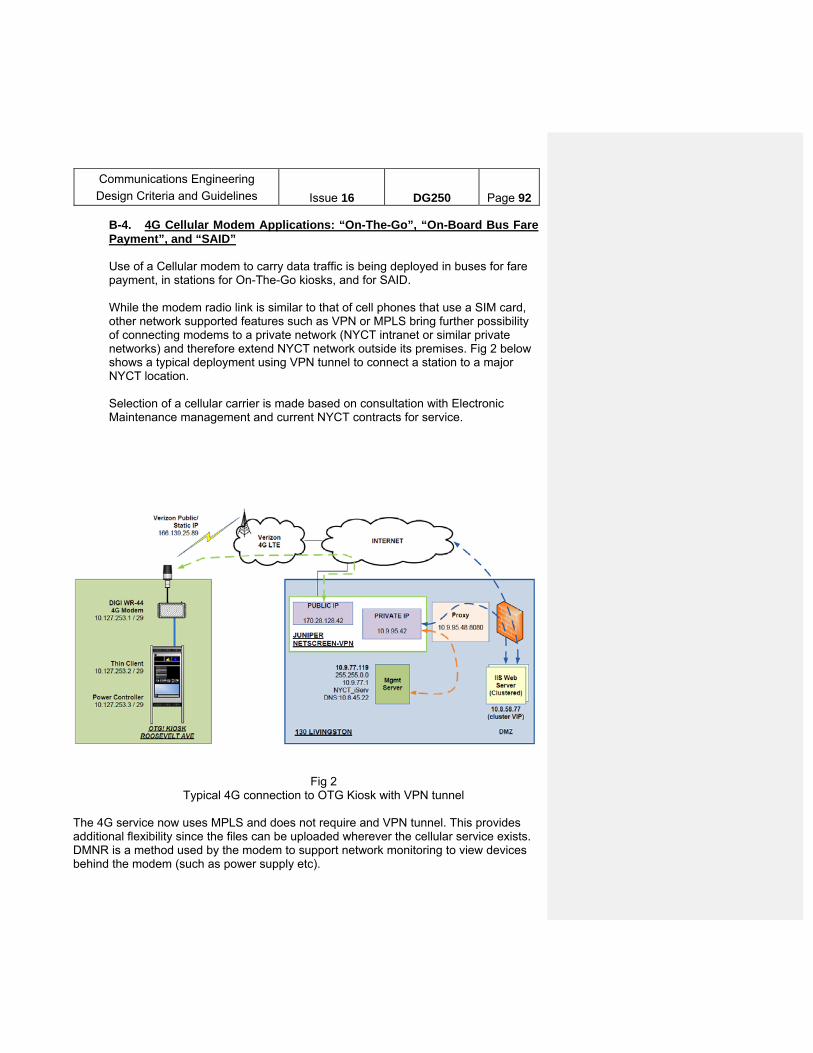
Communications Engineering
Design Criteria and Guidelines
Issue 16
DG250
Page 92
B-4. 4G Cellular Modem Applications: “On-The-Go”, “On-Board Bus Fare Payment”, and “SAID” Use of a Cellular modem to carry data traffic is being deployed in buses for fare payment, in stations for On-The-Go kiosks, and for SAID. While the modem radio link is similar to that of cell phones that use a SIM card, other network supported features such as VPN or MPLS bring further possibility of connecting modems to a private network (NYCT intranet or similar private networks) and therefore extend NYCT network outside its premises. Fig 2 below shows a typical deployment using VPN tunnel to connect a station to a major NYCT location. Selection of a cellular carrier is made based on consultation with Electronic Maintenance management and current NYCT contracts for service.
Fig 2 Typical 4G connection to OTG Kiosk with VPN tunnel
The 4G service now uses MPLS and does not require and VPN tunnel. This provides additional flexibility since the files can be uploaded wherever the cellular service exists. DMNR is a method used by the modem to support network monitoring to view devices behind the modem (such as power supply etc).

Communications Engineering
Design Criteria and Guidelines
Issue 16
DG250
Page 93
C. MIXED VOICE AND DATA WIRELESS COMMUNICATION SYSTEMS
C-1. Bus Radio System: The NYCT existing Bus Radio System was designed and implemented on 20 radio channels of 25 KHz each in the 800 MHz band. System Overview The existing system is a four site 800 MHz Analog Trunked Simulcast radio system integrated with a Computer Aided Dispatch (CAD) sub-system, and a 15 console sub-system. The four sites are interconnected via a dedicated 6 GHz microwave system. The radio system provides communications, dispatch, and control of field operations of the New York City Transit Department of Buses. There are about 6000 users of this system covering the 5 boroughs of NY City. The system was placed into service in 1990 and the main components of the system have been declared obsolete by the manufacturer. An interim upgrade to this system was made by replacing some of the critical components to keep the system running until a new system can be put in place to support DOB and MTA Bus operations. A new digital TDMA based, multisite Bus Radio System design had been proposed under contract W-32366. The contract has been awarded and construction is in progress. The objective of this new implementation is to provide a two-way land mobile digital radio communication to support both NYCT DOB (Department of Buses) and the MTA Bus Company. The system is envisioned to provide improved safety, service reliability, overall operating efficiency and increased capacity as it may use all present channels and newly allocated spectrum in the 700 MHz band. The System will use TETRA open standard with 4-slot TDMA technology to meet capacity and coverage requirements of Bus Radio System. General System Requirements: The radio system is required to operate 24/7/365 to support personnel in buses and support vehicles, as well as portables. The operations span over all the five boroughs of New York City, into the City of Yonkers and into portions of Northeastern New Jersey where there are routes. The radio system is required to serve approximately 4500 revenue vehicles (DOB), 1500 nonrevenue vehicles (DOB) and 1500 MTA Bus users with capacity expansion capability. Some of the general requirements of the new DOB/MTA Bus Radio System are:
o Open architecture-open standard, TDMA technology using 22 channels currently owned in 800 MHz spectrum and allocated 32

Communications Engineering
Design Criteria and Guidelines
Issue 16
DG250
Page 94
channels in 700 MHz spectrum. Channel bandwidth is 25KHz for each 700 and 800 MHz frequency
o Simultaneous Voice and Data Transmission- An integrated voice and data communication infrastructure comprising of multiple base station utilizing primarily MTA owned facilities
o A robust backhaul network primarily consisting of long and short haul microwave links. Existing NYCT network can be used on as needed basis.
o Furnishing of new Bus Command Center (being built under a separate contract) with a video wall in operating theatre, workstations, dispatch consoles, telephone PBX, voice recording, LAN subsystem, and other miscellaneous components.
o Smooth transition of bus operations from legacy system to new system and efficient retrofit of vehicles with minimum downtime.
o A user friendly, reliable Computer Aided Dispatch (CAD) system for efficient dispatching functionality for entire fleet.
Communications Engineering
Design Criteria and Guidelines
Issue 16
DG250
Page 95
Technical Performance Features:
o The new system will be digital, TDMA based operating on current radio frequencies in 800 MHz band and newly allocated 700 MHz band.
o This new system will provide Portable and Mobile radio coverage over 95% of the NYCT bus route coverage area.
o An all IP network that allows each base station and sub-system units to be centrally monitored easing maintenance.
o An acceptable delivered audio quality (DAQ) of greater than 3.4 will be acceptable with a minimum of -85dBm of received radio signal strength for uplink and downlink communications and corresponding BER and C/(I+N) ratio.
o The system radio coverage will be balanced for uplink and downlink
o The system should be open to future advancements/upgrades.
o The radio system will have the capability of interfacing to equipment that Dept of Buses will have on-board its buses.
Automatic Passenger counting Automatic Vehicle location and display Emergency activation of a covert microphone for emergencies
Design Guidelines:
Based on requirements, the following guidelines should be used while designing the system:
a. Analyze the current microwave system for existing coverage, user
capacity, limitations, dead zones and voice and data handling capacity. b. Analyze the existing system for current voice, data and radio site traffic
loading and future plans for increased traffic. c. Conduct detailed surveys of existing radio sites and preliminary surveys
of potential sites. At a minimum, these surveys should entail: Site location information (latitude, longitude, etc.) RF survey in terms of LOS availabilty to another site, local
coverage possibilty and RF environment (Open and blocked areas around the site)
Site structure details and conditions adjacent to the site Primary and backup power sources and fire alarm system Existing RF and network connections/details Photographs of all items of interest
Communications Engineering
Design Criteria and Guidelines
Issue 16
DG250
Page 96
d. Analyze coverage (uplink and downlink), intermodulation, carrier
interference, and human exposure to RF of MTA-owned/leased existing sites and potential new sites o Coverage Analysis: Coverage Modeling should be performed to
predict the theoretical radio coverage from a transmitter site over a given area. A simulation tool which incorporates various factors (choice of propagation model, path losses, terrain, clutter etc) and provides high-resolution should be used to perform coverage analysis. Since most of the systems are uplink limited, it is important to perform uplink coverage analysis.
o Intermodulation: Possibility of intermodulation at a particular site should be measured by calculating the potential additional frequencies that could generate after the frequencies in the channel configuration of the sites are mixed. There should be no third or fifth order products.
o Carrier Interference: A margin of 18 dB should be used to determine carrier interference.
e. Perform radio site selection based on coverage, voice and data traffic
loading, and construction feasibility analysis. o Voice Loading Analysis: Voice loading data includes the number and
length of voice radio calls carried by the system over a period of time. This data should be compared to the number on in-service units during that period of time to determine the typical voice traffic loading on a per unit basis.
o Data Loading Analysis: Data loading analysis can be performed by taking following into account- Inbound (from the buses) and outbound (to the buses) data
message size in bytes, Average number of each message type sent /user/hour Peak number of messages sent/user/hr The number of buses in service for the peak hour.
f. Select appropriate number of sites Number and location of sites will be based on their ability to provide required coverage as well as to account for redundancy and future expansion. In addition feasibility of construction shall also be taken into account.
g. Assign frequencies: The system must be designed using frequency
reuse (based on TDMA) architecture. This means that each channel should be deployed more than once. If one channel is assigned to a radio site, then that same channel should not be used in the adjacent or nearby sites. An effort should be made to use it as far away as possible to reduce interference (for example, the channel used in Bronx could be reused in Staten Island or in Brooklyn).Frequency planning and reuse shall also follow the contour, interference restrictions and other RF parameters as dictated by the FCC license for the use of that frequency.
Communications Engineering
Design Criteria and Guidelines
Issue 16
DG250
Page 97
h. Perform Backhaul Analysis and evaluate the options available for backhaul. Backhaul network could be a combination of Wireless/Microwave and Wired networks as needed.
i. Encryption options shall be explored and implemented to add to the security of BUS operations.
C-2. PUBLIC SAFETY 4.9GHz APPLICATIONS (HELP POINT)
1. System overview NYCT has implemented both wired and wireless Help Point (HP) devices within
its stations to provide its customers a method for reporting emergencies as well as obtain travel information. Over 200 stations have the 4.9 GHz network that was deployed along with WiFi service in stations through Transit Wireless under a license agreement with MTA. Many HP equipped stations communicate on the 4.9 GHz network.
The wireless HP system operates on the 4.9 GHz licensed Public Safety band using MESH technology. MESH technology provides inherent redundancy. In case a unit fails, the wireless HP can communicate directly with other wireless units directly.
One RF channel within the 4.9 GHz Band is used for each platform. Wireless Communication between Help Points are spectrally partitioned to the same side of the platform in order to avoid interruption of the RF signal links as trains arrive and depart. While two HPs typically cover a platform, the actual number of HPs per platform will depend on station configuration. Aggregators are used in conjunction with HPs to bring the traffic from each platform to a point where it can be connected via fiber to a communication room. The Aggregator grooms traffic and transfers it over to the opposite platform’s Aggregator unit using a separate directional 5.X GHz band RF link that is installed to propagate over the top of the train clearance which in the station. For redundancy, aggregators are used at the two ends of the platform. Also note that the current HP IP phone in the agent booth is connected to this network via a wired connection to the Aggregator. Fig 3 shows a typical deployment of Wireless HPs in a station using Access Points (AP) that operate in the 4.9 GHz public safety band. Note that for each AP
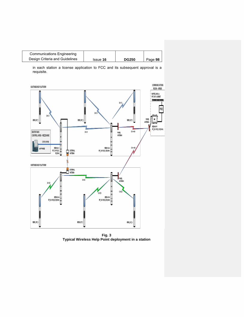
Communications Engineering
Design Criteria and Guidelines
Issue 16
DG250
Page 98
in each station a license application to FCC and its subsequent approval is a requisite.
Fig. 3 Typical Wireless Help Point deployment in a station

Communications Engineering
Design Criteria and Guidelines
Issue 16
DG250
Page 99
2. General System Requirements:
The system deployed shall meet the following functional requirements:
Support simultaneous Voice, Video and Data traffic The system is required to operate 24/7/365 per year. Provide RF coverage to 97 % of stations area and 100% of locations where
a fixed wireless HP exists. Utilize the Motorola/Zebra Technologies 7161 radio AP (4.9GHz / 5 GHz) May use either a wireless HP unit or a standard HP connected to an
external wireless Access Point (AP). For cross platform redundancy, the wireless HP configuration shall utilize
point to point 5GHz radio links at the ends of the platform via the designated “Aggregator” radio.
3. Technical performance requirements and configurations:
The following system configurations have been used for wireless HP deployments: 1) Wireless HP units connecting to Access Points (AP) within the station as
implemented the 4.9 GHZ system included with the Transit Wireless (TW) deployment of commercial wireless in the subway.
2) Wireless HP units connected to each other in frequency partitioned MESH
network as deployed in the majority of the NYCT stations that do not have TW network installations
3) Standard HP units connected to an external wireless AP network as
implemented at the IRT #4 Burnside Ave Station.
4.9 GHz HP Radio Standard Configuration o Radio shall typically be configured for a 20 MHz RF bandwidth o Frequencies of operation for the wireless HPs and external wireless APs
shall be 4955 MHz and 4975 MHz. Note: frequency coordination and licensing is required prior to design.
o RF output power is set at a typical +26dBm o As RF link budgets are directly related to data throughput, designers shall
refer to 802.11N multirate RF tables. The signal budget and design shall meet data rates of 20-60 Mbps
o Antennas may be placed within the HP or be placed externally to establish RF communications.
o MESH routing is configured on a per platform basis with redundant links provided through cross platform links.
Communications Engineering
Design Criteria and Guidelines
Issue 16
DG250
Page 100
5 GHZ Cross Platform Link Radio Configuration o Design configurations for the 5 GHz radio vary with each UNII band (5.15,
5.25, 5.47 GHz)
o Depending on configuration of the platform, Antennas may be external to the HP, directional, line of sight, and located such that they have an unobstructed path over the train clearance boundaries.
C-3. Millimetric Wave /Microwave Ethernet fixed radio links
1. System overview: Back haul using Ethernet links can be accomplished in many ways. Wired systems typically use Ethernet copper cable for short distances of up to 300ft and single mode fiber optic links for longer distances. However for distances beyond a few hundred feet, the wired systems become cost prohibitive due to labor installation as well as requirements for Ethernet extenders. For this situation, Millimetric wave and microwave Ethernet radio links become useful. These links provide the same interface as Ethernet (copper) or fiber but can be implemented when it is difficult or too costly to run cables.
2. General System requirements
The system designed shall meet the following functional requirements:
o Links shall be verified visually for clear line of sight; and i. be less than 0.5 miles on 60 GHz ii. be less than 3 miles on 70/80 GHz iii. be less than 12 miles on 23 GHz (microwave)
o equipment shall have interface options of either copper 100baseT / 1000baseT or fiber (single / multimode)
o Power consumption shall be typically below 50W for Millimetric link radios and below 100W for microwave
o Manufacturer built in tools shall be available for easy set up and alignment of the link.
o Include standard web based Network Management Service (NMS) features with options for in band or out of band operation
o Include an SNMP-MIB interface to integrate with existing centralized monitoring systems.
o 23 GHz and 70/80GHz systems must be licensed prior to design completion. 60 GHz systems are unlicensed.

Communications Engineering
Design Criteria and Guidelines
Issue 16
DG250
Page 101
3. Technical performance requirements and configurations:
A) The following are situations where different wireless methods have been used for point to point deployments:
1) To complete a link in which cable could not be run due to yard field conditions
2) Instead of traditional cabling (copper/fiber), an alternative wireless method to deploy a LAN Ring.
3) To provide a redundant non wired path for signal links in yards and other locations.
B) Performance of Millimetric / microwave links must be comparable to wired systems, since they integrate with such networks directly.
For the licensed bands of 23GHz and 70 / 80 GHz systems – ability to support legacy technologies (T1, T3, OC-3 etc.) along with Ethernet will be deemed an important advantage.
Redundant configuration of links in order to support redundant fiber links is essential for signaling systems.
System BER of 10-10 to 10-12 BER for data and 10-8 to 10-9 BER for VoIP applications is expected.
Multiple modulation schemes to support data rates starting from BPSK (lowest signal level) all the way to 128 QAM (highest signal levels) must be supported.
Round trip delay of < 100 u sec is important for certain real time transactions, over the network.
C-4. Commercial Cellular and WiFi in the Undeground Subway
1. System overview
Commercial Wireless service in underground Subway stations is provided through a license agreement between MTA and Transit Wireless Inc (TW). The commercial wireless system consists of Cellular Phone usage (voice and data) and WiFi. This service is extended to station platforms using a Distributed Antenna System (DAS) network deployed in underground stations that is fed from TW’s base station hotels through dedicated non-NYCT fiber optic cables.
Communications Engineering
Design Criteria and Guidelines
Issue 16
DG250
Page 102
The DAS network supports multiple Cellular and Internet Service Providers (ISP). This network is expected to have been extended to all below ground stations by the end of 2016.
2. General Design Guidelines
o The electromagnetic spectrum, used by present and future cellular and WiFi devices, may cause interference with current and planned MTA/NYCT systems. Consultation with the Communications Engineering’s Wireless Communications Group and Principal Engineer is required prior to system configuration to avoid interference that may be caused to existing operations that may include:
o Signal boosters o Existing WiFi systems or cellular modems o CBTC operations on 2.4 GHz
o The TW service provides coverage in stations only (platform, mezzanine and
passage areas). It is not intended to provide coverage in subway tunnels or between stations. No equipment or antennas shall be installed outside of stations
o A variety of NYCT applications access cellular service using 4G modems that
do not rely on accessing TW’s network. These systems may have antennas routed to the street or stairwells where service is obtained directly and are not part of TW’s network.
3. Technical performance requirements and configurations: o TW provides drawings and technical specifications which may follow different
requirements than NYCT specifications o Use of Hybriflex cables in lieu of rigid conduit o Running cables on platform side of lighting or on wall side of platform o Placement of antennas and junction boxes below 8 foot
Each station is submitted for review and exceptions taken on a case by case basis.
Communications Engineering
Design Criteria and Guidelines
Issue 16
DG250
Page 103
C-5. Cellular Network Modem
1. System overview
Cellular service (voice or data) within the MTA/NYCT subway system and facilities has a potential of providing important voice and data capabilities. Cell phone usage is extended in many station platforms using a DAS network deployed by Transit Wireless Inc. In other unequipped stations, where no coverage is available antennas must be placed outdoors (the street). A similar arrangement is needed, if there are NYCT facilities that do not have in-door cellular service. NYCT uses cellular modems for data access for many applications such as the On-The Go- Kiosk and the ISIM-B.
2. General Design Guidelines For access to the cellular system for data capabilities A variety of applications access cellular service using a 4G modem.
The modems support MPLS / DMNR to enable access to NYCT’s private network that utilizes the public cellular network as a backbone. This feature is subscribed to by NYCT at a corporate level. It is essential to provide designs for a variety of machine-to-machine applications. Authentication shall be verified in two parts – firewall from / to NYCT and cellular authentication supported from the service provider.
Data rates of up to 20 Mbps to carry a variety of traffic including CCTV, high, medium or low speed data streams (such as SCADA).
At this time most modem and other applications deployed are designed to work
on 4G (with 3G as a back-up in case 4G service becomes unavailable).
To extend cellular service for in-door building coverage: A signal booster is not an approved device The cellular carrier of choice must be contacted to provide a femo-cell or DAS
network
3. Technical performance requirements and configurations:
The requirements vary for each application and such products shall be submitted along with specifications and drawings for each application and design.

Communications Engineering
Design Criteria and Guidelines
Issue 16
DG250
Page 104
IV CONTRACT CATEGORY/SPECIFIC SYSTEM MATRIX
REQUIRED EQUIPMENT Contract Category
Job Description Antenna Cables & Assoc.
Antennas Conn. & Accesso.
Cable Encls.
Brack. Suppts.
Base Stns.
Remote Receivers
Carrier Equipt.
Antenna Cable Replace- Ment
Installing, testing and placing into operation of radiating and non-radiating antenna cables to provide complete two-way communications for Police and transportation personnel with their respective command centers for all boroughs.
X
X
X
X
Station Modern- ization (Radio Equip-ment)
Relocating (rerouting), installing, testing and placing into operation of radio equipment in support of project management program.
X
X
X
X
X
X
X
X
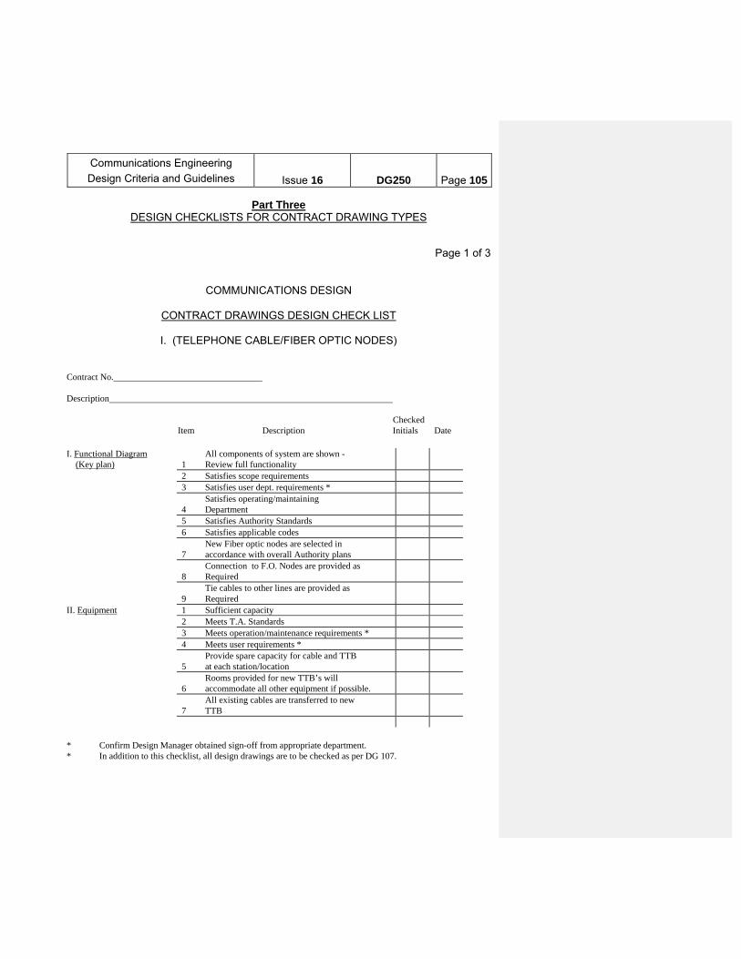
Communications Engineering
Design Criteria and Guidelines
Issue 16
DG250
Page 105
Part Three DESIGN CHECKLISTS FOR CONTRACT DRAWING TYPES
Page 1 of 3
COMMUNICATIONS DESIGN
CONTRACT DRAWINGS DESIGN CHECK LIST
I. (TELEPHONE CABLE/FIBER OPTIC NODES) Contract No. Description Checked Item Description Initials Date I. Functional Diagram (Key plan)
1
All components of system are shown - Review full functionality
2 Satisfies scope requirements 3 Satisfies user dept. requirements *
4 Satisfies operating/maintaining Department
5 Satisfies Authority Standards 6 Satisfies applicable codes
7 New Fiber optic nodes are selected in accordance with overall Authority plans
8
Connection to F.O. Nodes are provided as Required
9
Tie cables to other lines are provided as Required
II. Equipment 1 Sufficient capacity 2 Meets T.A. Standards 3 Meets operation/maintenance requirements * 4 Meets user requirements *
5 Provide spare capacity for cable and TTB at each station/location
6
Rooms provided for new TTB’s will accommodate all other equipment if possible.
7
All existing cables are transferred to new TTB
* Confirm Design Manager obtained sign-off from appropriate department. * In addition to this checklist, all design drawings are to be checked as per DG 107.

Communications Engineering
Design Criteria and Guidelines
Issue 16
DG250
Page 106
Page 2 of 3
COMMUNICATIONS DESIGN
CONTRACT DRAWINGS DESIGN CHECK LIST
(TELEPHONE CABLE/FIBER OPTIC NODES) Contract No. Description Checked Item Description Initials Date III. Equipment and Cable Layout
1
Approximate location and layout of all cable and equipment are shown
2
Location satisfies operation/maintenance requirements *
3
Equipment location has approval of dept. having jurisdiction over room. *
4
Cable and conduit layout do not interfere with modernization projects, other existing equipment, secure Stations Clearinghouse approval for run
5
Check for other Contracts in the are and coordinate.
6 Maintainability (Safety) *
7 Check for feasibility of large cable bends/ offsets
8
Investigate duct availability for preferred cable route
9
Room layouts to allow for expansion and placing future equipment
IV. Wire & Cable 1 Size (AWG and # of pairs) 2 Meets T.A. standards 3 Spare requirements are met
4 Termination facilities in existing telephone terminal boxes are available
5
Cross connection to existing systems are provided
6 Required AC power feeds are shown
7 Locate new splices in place of old splices for new cable tails (Check nearest manhole)
* Confirm Design Manager obtained sign-off from appropriate department.
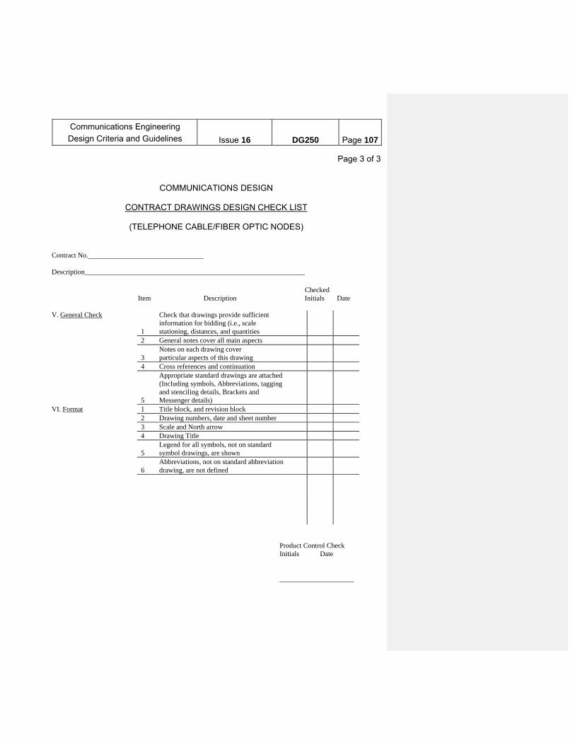
Communications Engineering
Design Criteria and Guidelines
Issue 16
DG250
Page 107
Page 3 of 3
COMMUNICATIONS DESIGN
CONTRACT DRAWINGS DESIGN CHECK LIST
(TELEPHONE CABLE/FIBER OPTIC NODES) Contract No. Description Checked Item Description Initials Date V. General Check
1
Check that drawings provide sufficient information for bidding (i.e., scale stationing, distances, and quantities
2 General notes cover all main aspects
3 Notes on each drawing cover particular aspects of this drawing
4 Cross references and continuation
5
Appropriate standard drawings are attached (Including symbols, Abbreviations, tagging and stenciling details, Brackets and Messenger details)
VI. Format 1 Title block, and revision block 2 Drawing numbers, date and sheet number 3 Scale and North arrow 4 Drawing Title
5 Legend for all symbols, not on standard symbol drawings, are shown
6
Abbreviations, not on standard abbreviation drawing, are not defined
Product Control Check Initials Date _____________________
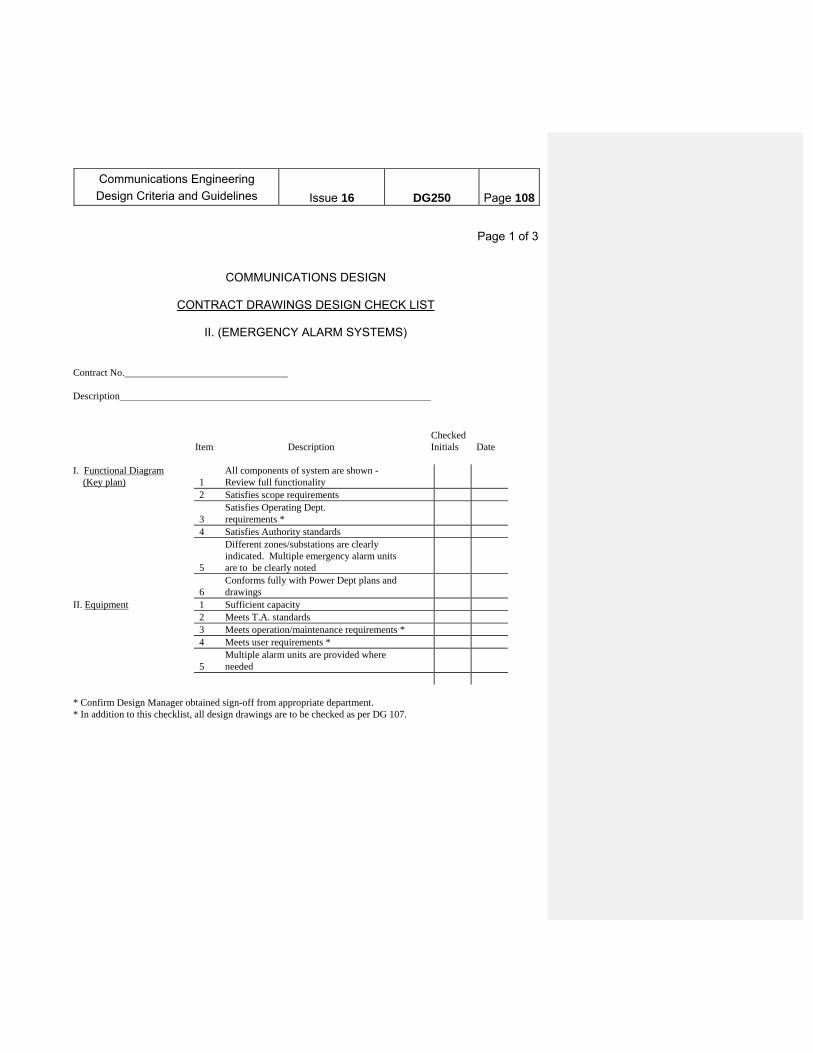
Communications Engineering
Design Criteria and Guidelines
Issue 16
DG250
Page 108
Page 1 of 3
COMMUNICATIONS DESIGN
CONTRACT DRAWINGS DESIGN CHECK LIST
II. (EMERGENCY ALARM SYSTEMS) Contract No. Description Checked Item Description Initials Date I. Functional Diagram (Key plan)
1
All components of system are shown - Review full functionality
2 Satisfies scope requirements
3 Satisfies Operating Dept. requirements *
4 Satisfies Authority standards
5
Different zones/substations are clearly indicated. Multiple emergency alarm units are to be clearly noted
6
Conforms fully with Power Dept plans and drawings
II. Equipment 1 Sufficient capacity 2 Meets T.A. standards 3 Meets operation/maintenance requirements * 4 Meets user requirements *
5 Multiple alarm units are provided where needed
* Confirm Design Manager obtained sign-off from appropriate department. * In addition to this checklist, all design drawings are to be checked as per DG 107.
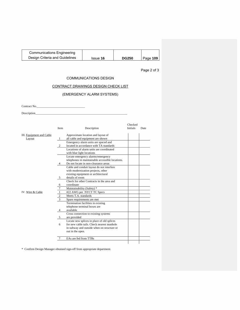
Communications Engineering
Design Criteria and Guidelines
Issue 16
DG250
Page 109
Page 2 of 3
COMMUNICATIONS DESIGN
CONTRACT DRAWINGS DESIGN CHECK LIST
(EMERGENCY ALARM SYSTEMS)
Contract No. Description Checked Item Description Initials Date III. Equipment and Cable Layout
1
Approximate location and layout of all cable and equipment are shown
2
Emergency alarm units are spaced and located in accordance with TA standards
Locations of alarm units are coordinated with blue light locations
4
Locate emergency alarms/emergency telephones in maintainable accessible locations. Do not locate in non-clearance areas
5
Cable and conduit layout do not interfere with modernization projects, other existing equipment or architectural details of room
6
Check for other Contracts in the area and coordinate
7 Maintainability (Safety) * IV. Wire & Cable 1 #22 AWG per NYCT TC Specs 2 Meets T.A. standards 3 Spare requirements are met
4
Termination facilities in existing telephone terminal boxes are available
5
Cross connection to existing systems are provided
6
Locate new splices in place of old splices for new cable tails. Check nearest manhole in subway and outside when on structure or out in the open.
7 EAs are fed from TTBs * Confirm Design Manager obtained sign-off from appropriate department.
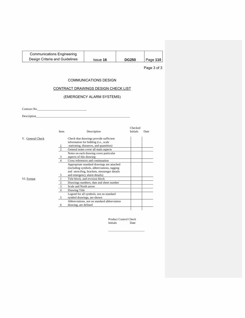
Communications Engineering
Design Criteria and Guidelines
Issue 16
DG250
Page 110
Page 3 of 3
COMMUNICATIONS DESIGN
CONTRACT DRAWINGS DESIGN CHECK LIST
(EMERGENCY ALARM SYSTEMS) Contract No. Description Checked Item Description Initials Date V. General Check
1
Check that drawings provide sufficient information for bidding (i.e., scale stationing, distances, and quantities)
2 General notes cover all main aspects
3 Notes on each drawing cover particular aspects of this drawing
4 Cross references and continuation
5
Appropriate standard drawings are attached (including symbols, abbreviations, tagging and stenciling, brackets, messenger details and emergency alarm details)
VI. Format 1 Title block, and revision block 2 Drawings numbers, date and sheet number 3 Scale and North arrow 4 Drawing Title
5 Legend for all symbols, not on standard symbol drawings, are shown
6
Abbreviations, not on standard abbreviation drawing, are defined
Product Control Check Initials Date ________________________
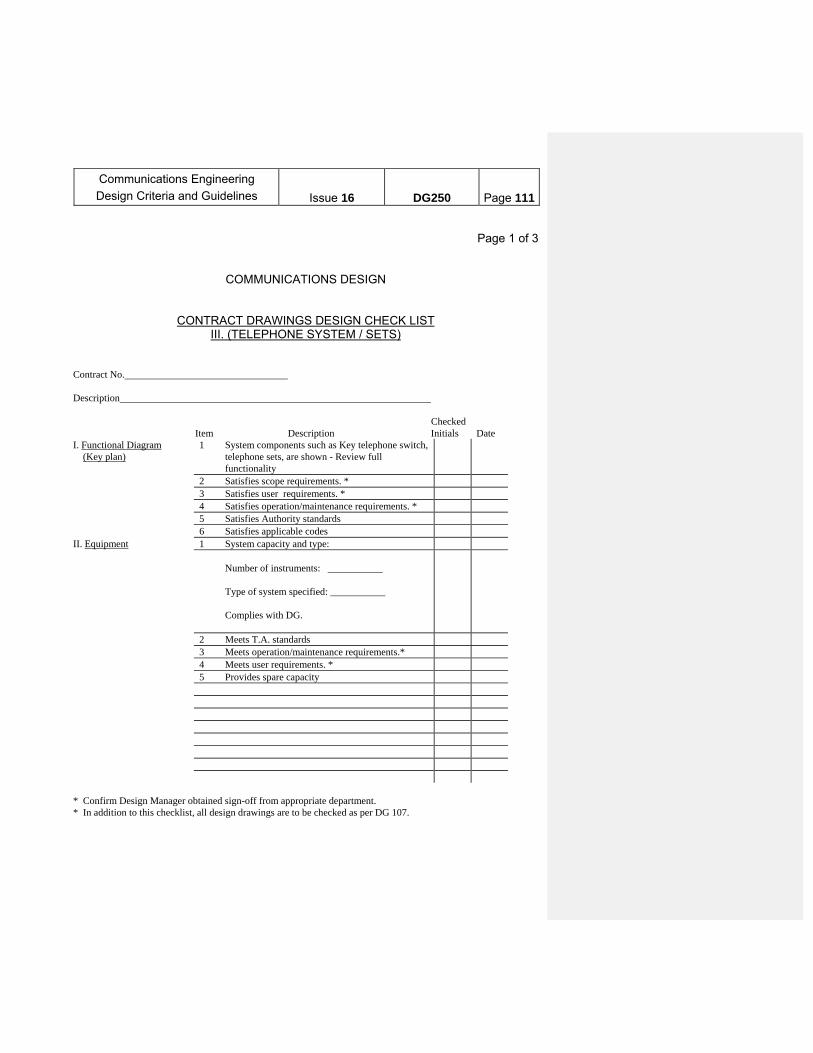
Communications Engineering
Design Criteria and Guidelines
Issue 16
DG250
Page 111
Page 1 of 3
COMMUNICATIONS DESIGN
CONTRACT DRAWINGS DESIGN CHECK LIST III. (TELEPHONE SYSTEM / SETS)
Contract No. Description Checked Item Description Initials Date I. Functional Diagram (Key plan)
1 System components such as Key telephone switch, telephone sets, are shown - Review full functionality
2 Satisfies scope requirements. * 3 Satisfies user requirements. * 4 Satisfies operation/maintenance requirements. * 5 Satisfies Authority standards 6 Satisfies applicable codes II. Equipment 1 System capacity and type:
Number of instruments: ___________ Type of system specified: ___________ Complies with DG.
2 Meets T.A. standards 3 Meets operation/maintenance requirements.* 4 Meets user requirements. * 5 Provides spare capacity * Confirm Design Manager obtained sign-off from appropriate department. * In addition to this checklist, all design drawings are to be checked as per DG 107.
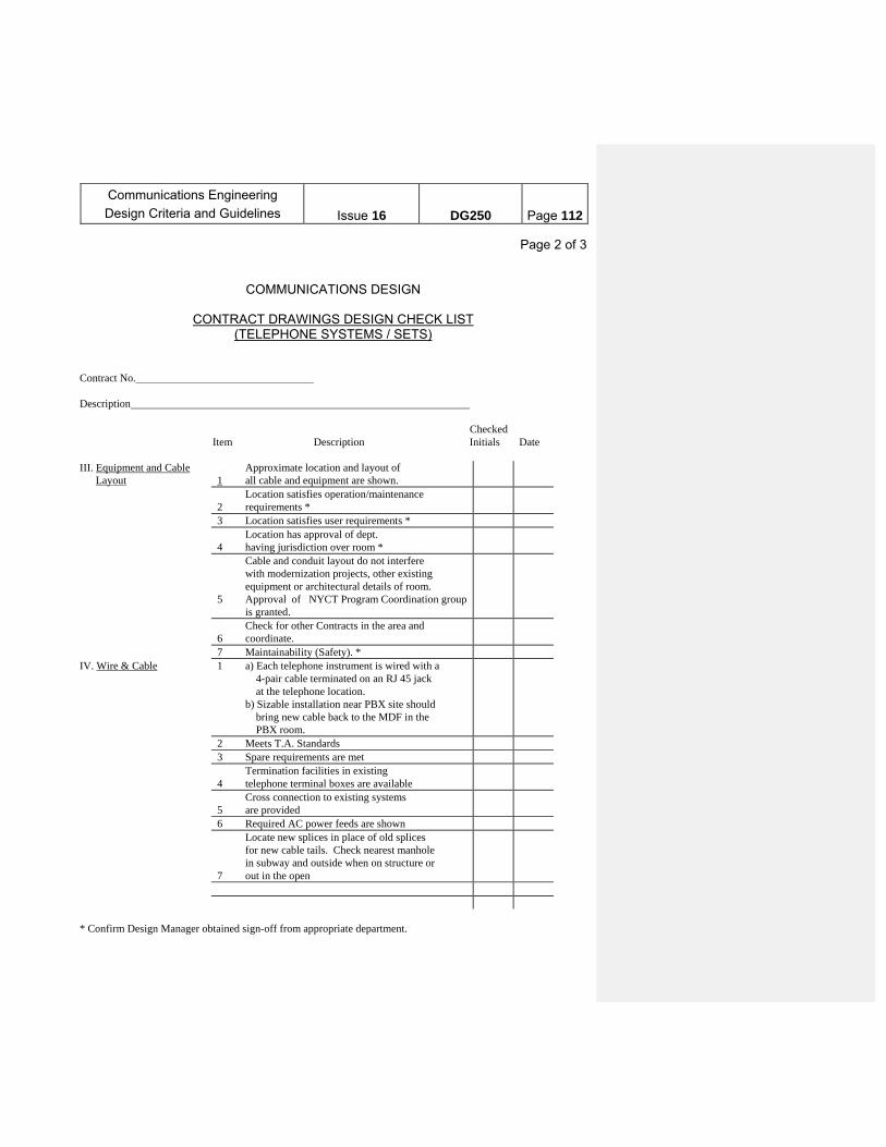
Communications Engineering
Design Criteria and Guidelines
Issue 16
DG250
Page 112
Page 2 of 3
COMMUNICATIONS DESIGN
CONTRACT DRAWINGS DESIGN CHECK LIST (TELEPHONE SYSTEMS / SETS)
Contract No. Description Checked Item Description Initials Date III. Equipment and Cable Layout
1
Approximate location and layout of all cable and equipment are shown.
2
Location satisfies operation/maintenance requirements *
3 Location satisfies user requirements *
4 Location has approval of dept. having jurisdiction over room *
5
Cable and conduit layout do not interfere with modernization projects, other existing equipment or architectural details of room. Approval of NYCT Program Coordination group is granted.
6
Check for other Contracts in the area and coordinate.
7 Maintainability (Safety). * IV. Wire & Cable 1 a) Each telephone instrument is wired with a
4-pair cable terminated on an RJ 45 jack at the telephone location. b) Sizable installation near PBX site should bring new cable back to the MDF in the PBX room.
2 Meets T.A. Standards 3 Spare requirements are met
4 Termination facilities in existing telephone terminal boxes are available
5
Cross connection to existing systems are provided
6 Required AC power feeds are shown
7
Locate new splices in place of old splices for new cable tails. Check nearest manhole in subway and outside when on structure or out in the open
* Confirm Design Manager obtained sign-off from appropriate department.
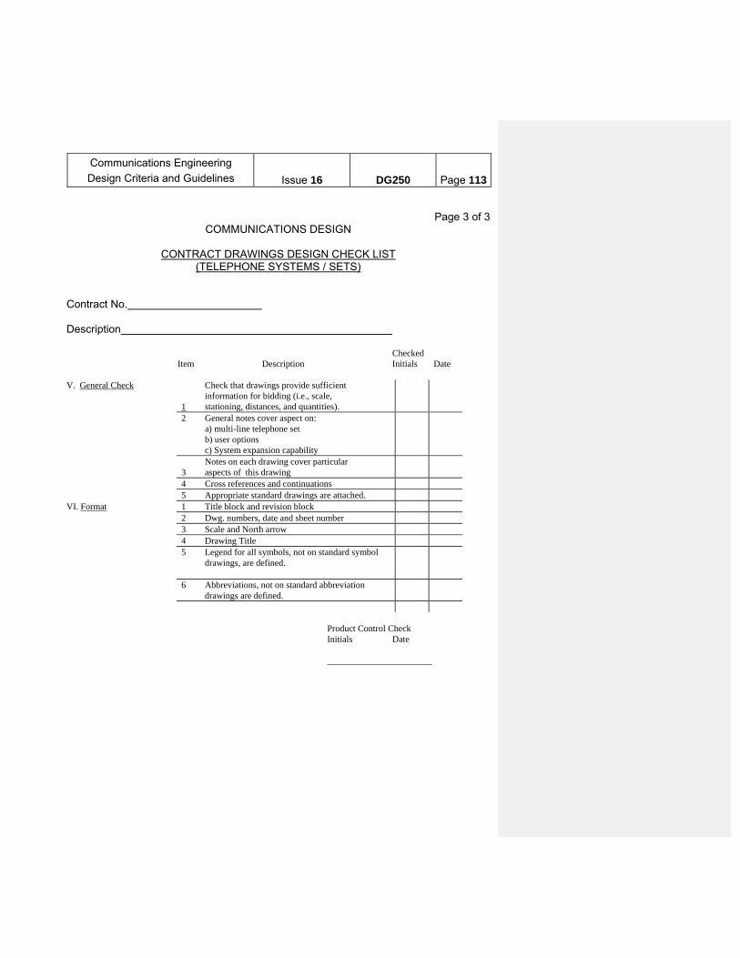
Communications Engineering
Design Criteria and Guidelines
Issue 16
DG250
Page 113
Page 3 of 3
COMMUNICATIONS DESIGN
CONTRACT DRAWINGS DESIGN CHECK LIST (TELEPHONE SYSTEMS / SETS)
Contract No. Description Checked Item Description Initials Date V. General Check
1
Check that drawings provide sufficient information for bidding (i.e., scale, stationing, distances, and quantities).
2
General notes cover aspect on: a) multi-line telephone set b) user options c) System expansion capability
3
Notes on each drawing cover particular aspects of this drawing
4 Cross references and continuations 5 Appropriate standard drawings are attached. VI. Format 1 Title block and revision block 2 Dwg. numbers, date and sheet number 3 Scale and North arrow 4 Drawing Title 5 Legend for all symbols, not on standard symbol
drawings, are defined.
6 Abbreviations, not on standard abbreviation drawings are defined.
Product Control Check Initials Date _______________________

Communications Engineering
Design Criteria and Guidelines
Issue 16
DG250
Page 114
Page 1 of 3
COMMUNICATIONS DESIGN
CONTRACT DRAWINGS DESIGN CHECK LIST IV. (PUBLIC ADDRESS / CUSTOMER INFORMATION SCREEN SYSTEMS)
Contract No. Description Checked Item Description Initials Date I. Functional Diagram (Key plan)
1 System components such as UPS, Speakers, and Speaker Enclosure Customer Information Screens (C.I.S.) etc. are shown - Review full functionality.
2 Satisfies scope requirements. 3 Satisfies user requirements. * 4 Satisfies operation/maintenance
requirements. *
5 Satisfies Authority standards. 6 Satisfies applicable codes; satisfies ADA
Requirements.
II. Equipment 1 Sufficient capacity 2 Meets Authority standards. 3 Meets operation/maintenance requirements. * 4 Meets user requirements. * 5 Equipment type is coordinated with existing/future PA systems * Confirm Design Manager obtained sign-off from appropriate department. * In addition to this checklist, all design drawings are to be checked as per DG 107.

Communications Engineering
Design Criteria and Guidelines
Issue 16
DG250
Page 115
Page 2 of 3
COMMUNICATIONS DESIGN
CONTRACT DRAWINGS DESIGN CHECK LIST (PUBLIC ADDRESS / CUSTOMER INFORMATION SCREEN SYSTEMS)
Contract No. Description Checked Item Description Initials Date III. Equipment and Cable Layout
1 Approximate location and layout of all cable and equipment are shown.
2 Location satisfies operation/maintenance requirements. Speakers are located in control and platform areas and other areas as per scope of work.
3 Speakers are spaced as per Standards. 4 Location of Communications Room has
approval of Stations Clearing House.
5 Cable and conduit layout do not interfere with modernization projects, other existing equipment or architectural details of room approval of station Clearing House is granted.
6 Check for other Contracts in the area and coordinate.
7 Maintainability (Safety). * IV. Wire & Cable 1 Cables and wire sizes are shown and are as per
Specs.
2 Meets T.A. TC Specifications 3 Spare requirements are met 4 Termination facilities in existing
telephone boxes are available.
5 Cross connections to existing systems are provided.
6 Required AC power feeds are shown 7 Locate new splices in place of old splices
for new cable tails. Check nearest manhole in subway and outside when on structure or out in the open
* Confirm Design Manager obtained sign-off from appropriate department.
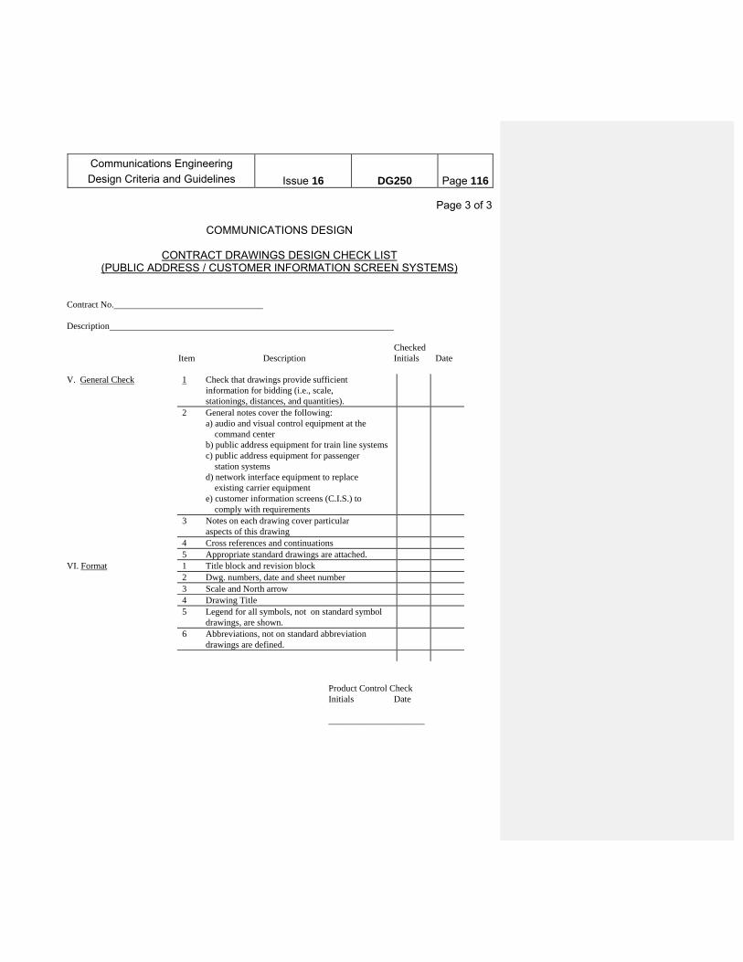
Communications Engineering
Design Criteria and Guidelines
Issue 16
DG250
Page 116
Page 3 of 3
COMMUNICATIONS DESIGN
CONTRACT DRAWINGS DESIGN CHECK LIST (PUBLIC ADDRESS / CUSTOMER INFORMATION SCREEN SYSTEMS)
Contract No. Description Checked Item Description Initials Date V. General Check 1 Check that drawings provide sufficient
information for bidding (i.e., scale, stationings, distances, and quantities).
2 General notes cover the following: a) audio and visual control equipment at the command center b) public address equipment for train line systems c) public address equipment for passenger station systems d) network interface equipment to replace existing carrier equipment e) customer information screens (C.I.S.) to comply with requirements
3 Notes on each drawing cover particular aspects of this drawing
4 Cross references and continuations 5 Appropriate standard drawings are attached.VI. Format 1 Title block and revision block 2 Dwg. numbers, date and sheet number 3 Scale and North arrow 4 Drawing Title 5 Legend for all symbols, not on standard symbol
drawings, are shown.
6 Abbreviations, not on standard abbreviation drawings are defined.
Product Control Check Initials Date _____________________
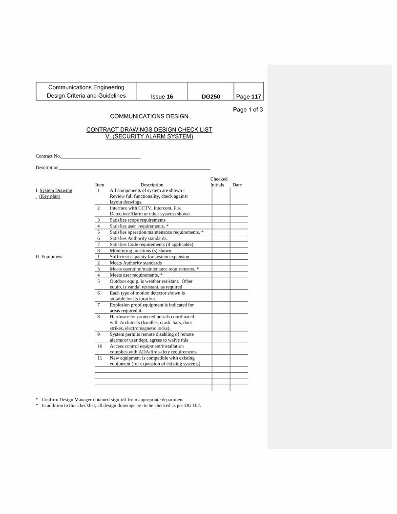
Communications Engineering
Design Criteria and Guidelines
Issue 16
DG250
Page 117
Page 1 of 3 COMMUNICATIONS DESIGN
CONTRACT DRAWINGS DESIGN CHECK LIST
V. (SECURITY ALARM SYSTEM) Contract No. Description Checked Item Description Initials Date I. System Drawing (Key plan)
1 All components of system are shown - Review full functionality, check against layout drawings.
2 Interface with CCTV, Intercom, Fire Detection/Alarm or other systems shown.
3 Satisfies scope requirements 4 Satisfies user requirements. * 5 Satisfies operation/maintenance requirements. * 6 Satisfies Authority standards. 7 Satisfies Code requirements (if applicable) 8 Monitoring locations (s) shown II. Equipment 1 Sufficient capacity for system expansion 2 Meets Authority standards 3 Meets operation/maintenance requirements. * 4 Meets user requirements. * 5 Outdoor equip. is weather resistant. Other
equip. is vandal resistant, as required
6 Each type of motion detector shown is suitable for its location.
7 Explosion proof equipment is indicated for areas required it.
8 Hardware for protected portals coordinated with Architects (handles, crash bars, door strikes, electromagnetic locks).
9 System permits remote disabling of remote alarms or user dept. agrees to waive this
10 Access control equipment/installation complies with ADA/fire safety requirements
11 New equipment is compatible with existing equipment (for expansion of existing systems).
* Confirm Design Manager obtained sign-off from appropriate department * In addition to this checklist, all design drawings are to be checked as per DG 107.

Communications Engineering
Design Criteria and Guidelines
Issue 16
DG250
Page 118
Page 2 of 3 COMMUNICATIONS DESIGN
CONTRACT DRAWINGS DESIGN CHECK LIST
(SECURITY ALARM SYSTEM) Contract No. Description Checked Item Description Initials Date III. Equipment and Cable Layout
1 Approximate location and layout of all cable and equipment are shown
2 Location satisfies operation/maintenance requirements. *
3 Location satisfies user requirements. * 4 Location has approval of dept.
having jurisdiction over room.
5 Cable and conduit layout do not interfere with modernization projects, other exist. equipment or architectural details of room.
6 Check for other Contracts in the area and coordinate.
7 Maintainability (Safety). * 8 Communications/Security Room size adequate 9 Drawings indicate zones for emergency exits,
intermittent zones (utility rooms), and zones which are regularly switched on and off (such as offices).
10 Alarm zone/location for each device is indicated (cross check with system drawing)
11 Tamper switches indicated as required (includes protection for equipment cabinets).
12 Intercom stations shown as required at portals protected by intrusion detection or access control devices.
13 Power sources indicated for remotely located devices.
14 Local alarms/strobes indicated at appropriate locations.
15 Strobes positioned for visibility to personnel investigating alarm condition.
16 Drawings indicate required signs, such as “no trespassing”. “emergency exit”. signs warning that vehicles are subject to search and signs for intercom operation.
17 Voltage drops within acceptable ranges for remote equipment.
* Confirm Design Manager obtained sign-off from appropriate department
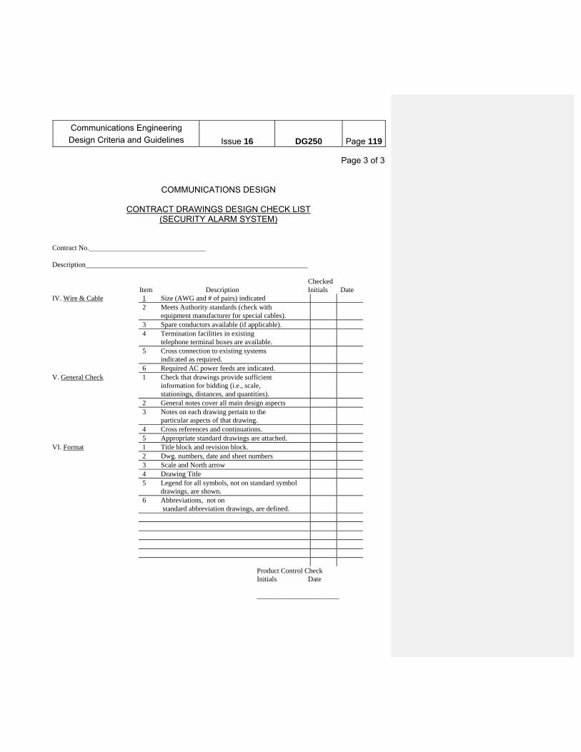
Communications Engineering
Design Criteria and Guidelines
Issue 16
DG250
Page 119
Page 3 of 3
COMMUNICATIONS DESIGN
CONTRACT DRAWINGS DESIGN CHECK LIST (SECURITY ALARM SYSTEM)
Contract No. Description Checked Item Description Initials Date IV. Wire & Cable 1 Size (AWG and # of pairs) indicated 2 Meets Authority standards (check with
equipment manufacturer for special cables).
3 Spare conductors available (if applicable). 4 Termination facilities in existing
telephone terminal boxes are available.
5 Cross connection to existing systems indicated as required.
6 Required AC power feeds are indicated. V. General Check 1 Check that drawings provide sufficient
information for bidding (i.e., scale, stationings, distances, and quantities).
2 General notes cover all main design aspects 3 Notes on each drawing pertain to the
particular aspects of that drawing.
4 Cross references and continuations. 5 Appropriate standard drawings are attached. VI. Format 1 Title block and revision block. 2 Dwg. numbers, date and sheet numbers 3 Scale and North arrow 4 Drawing Title 5 Legend for all symbols, not on standard symbol
drawings, are shown.
6 Abbreviations, not on standard abbreviation drawings, are defined.
Product Control Check Initials Date _______________________
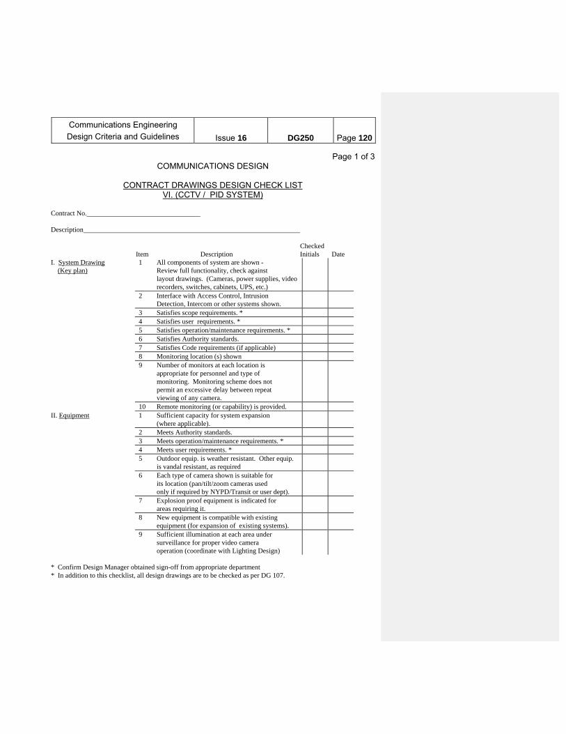
Communications Engineering
Design Criteria and Guidelines
Issue 16
DG250
Page 120
Page 1 of 3 COMMUNICATIONS DESIGN
CONTRACT DRAWINGS DESIGN CHECK LIST
VI. (CCTV / PID SYSTEM)
Contract No. Description Checked Item Description Initials Date I. System Drawing (Key plan)
1 All components of system are shown - Review full functionality, check against layout drawings. (Cameras, power supplies, video recorders, switches, cabinets, UPS, etc.)
2 Interface with Access Control, Intrusion Detection, Intercom or other systems shown.
3 Satisfies scope requirements. * 4 Satisfies user requirements. * 5 Satisfies operation/maintenance requirements. * 6 Satisfies Authority standards. 7 Satisfies Code requirements (if applicable) 8 Monitoring location (s) shown 9 Number of monitors at each location is
appropriate for personnel and type of monitoring. Monitoring scheme does not permit an excessive delay between repeat viewing of any camera.
10 Remote monitoring (or capability) is provided. II. Equipment 1 Sufficient capacity for system expansion
(where applicable).
2 Meets Authority standards. 3 Meets operation/maintenance requirements. * 4 Meets user requirements. * 5 Outdoor equip. is weather resistant. Other equip.
is vandal resistant, as required
6 Each type of camera shown is suitable for its location (pan/tilt/zoom cameras used only if required by NYPD/Transit or user dept).
7 Explosion proof equipment is indicated for areas requiring it.
8 New equipment is compatible with existing equipment (for expansion of existing systems).
9 Sufficient illumination at each area under surveillance for proper video camera operation (coordinate with Lighting Design)
* Confirm Design Manager obtained sign-off from appropriate department * In addition to this checklist, all design drawings are to be checked as per DG 107.

Communications Engineering
Design Criteria and Guidelines
Issue 16
DG250
Page 121
Page 2 of 3
COMMUNICATIONS DESIGN
CONTRACT DRAWINGS DESIGN CHECK LIST (CCTV / PID SYSTEM)
Contract No. Description Checked Item Description Initials Date III. Equipment and Cable Layout
1 Approximate location and layout of all cable and equipment are shown
2 Location satisfies operation/maintenance requirements. *
3 Location satisfies user requirements. * 4 Location has approval of dept.
having jurisdiction over room. *
5 Cable and conduit layout do not interfere with modernization projects, other exist. equipment or architectural details of room.
6 Check for other Contracts in the area and coordinate
7 Maintainability (Safety). * 8 Communications/Security Room size adequate. 9 Drawings indicate video camera numbers
(cross check with system drawing).
10 Drawings indicate area under surveillance for each camera (table format if required)
11 Tamper switches indicated as required (includes protection for equipment cabinets)
12 Intercom stations shown as required at portals protected by intrusion detection, access control or video surveillance.
13 Power sources indicated for remotely located devices.
14 Drawings indicate required signs, such as “no trespassing”, “emergency exit”, signs warning that vehicles are subject to search, and signs for intercom operation.
15 The design does not indicate any areas under covert surveillance, except by written permission of NYPD/Transit.
* Confirm Design Manager obtained sign-off from appropriate department.
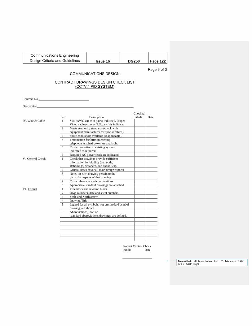
Communications Engineering
Design Criteria and Guidelines
Issue 16
DG250
Page 122
Page 3 of 3 COMMUNICATIONS DESIGN
CONTRACT DRAWINGS DESIGN CHECK LIST
(CCTV / PID SYSTEM) Contract No. Description Checked Item Description Initials Date IV. Wire & Cable 1 Size (AWG and # of pairs) indicated. Proper
Video cable (coax or F.O…etc.) is indicated
2 Meets Authority standards (check with equipment manufacturer for special cables).
3 Spare conductors available (if applicable). 4 Termination facilities in existing
telephone terminal boxes are available.
5 Cross connection to existing systems indicated as required.
6 Required AC power feeds are indicated V. General Check 1 Check that drawings provide sufficient
information for bidding (i.e., scale, stationings, distances, and quantities).
2 General notes cover all main design aspects 3 Notes on each drawing pertain to the
particular aspects of that drawing.
4 Cross references and continuations 5 Appropriate standard drawings are attached. VI. Format 1 Title block and revision block 2 Dwg. numbers, date and sheet numbers 3 Scale and North arrow 4 Drawing Title 5 Legend for all symbols, not on standard symbol
drawing, are shown.
6 Abbreviations,, not on standard abbreviations drawings, are defined.
Product Control Check Initials Date ___________________
Formatted: Left, None, Indent: Left: 0", Tab stops: 0.46",Left + 5.84", Right
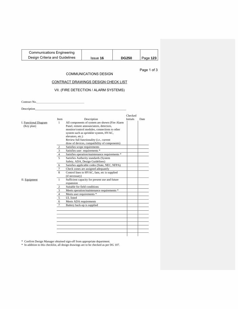
Communications Engineering
Design Criteria and Guidelines
Issue 16
DG250
Page 123
Page 1 of 3
COMMUNICATIONS DESIGN
CONTRACT DRAWINGS DESIGN CHECK LIST
VII. (FIRE DETECTION / ALARM SYSTEMS) Contract No. Description Checked Item Description Initials Date I. Functional Diagram (Key plan)
1 All components of system are shown (Fire Alarm Panel, remote announciators, detectors, monitor/control modules, connections to other system such as sprinkler system, HVAC, elevators, etc.) Review full functionality (i.e., current draw of devices, compatibility of components)
2 Satisfies scope requirements 3 Satisfies user requirements * 4 Satisfies operation/maintenance requirements * 5 Satisfies Authority standards (System
Safety, ADA, Design Guidelines)
6 Satisfies applicable codes (State, NEC, NFPA) 7 Check zones are assigned adequately 8 Control lines to HVAC, fans, etc is supplied
(if necessary)
II. Equipment 1 Sufficient capacity for present use and future expansion
2 Suitable for field conditions 3 Meets operation/maintenance requirements * 4 Meets user requirements * 5 UL listed 6 Meets ADA requirements 7 Battery back-up is supplied * Confirm Design Manager obtained sign-off from appropriate department. * In addition to this checklist, all design drawings are to be checked as per DG 107.
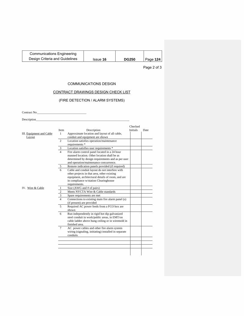
Communications Engineering
Design Criteria and Guidelines
Issue 16
DG250
Page 124
Page 2 of 3
COMMUNICATIONS DESIGN
CONTRACT DRAWINGS DESIGN CHECK LIST
(FIRE DETECTION / ALARM SYSTEMS) Contract No. Description Checked Item Description Initials Date III. Equipment and Cable Layout
1 Approximate location and layout of all cable, conduit and equipment are shown
2 Location satisfies operation/maintenance requirements *
3 Location satisfies user requirements * 4 Fire alarm control panel located in a 24 hour
manned location. Other location shall be as determined by design requirements and as per user and operation/maintenance concurrence.
5 Remote indication panels provided (if required) 6 Cable and conduit layout do not interfere with
other projects in that area, other existing equipment, architectural details of room, and are in compliance w/station Clearinghouse requirements.
IV. Wire & Cable 1 Size (AWG and # of pairs) 2 Meets NYCTA Wire & Cable standards 3 Spare requirements are met 4 Connections to existing main fire alarm panel (s)
(if present) are provided
5 Required AC power feeds from a FCO box are shown
6 Run independently in rigid hot dip galvanized steel conduit in work/public areas, in EMT/on cable ladder above hung ceiling or in wiremold in finished area.
7 AC power cables and other fire alarm system wiring (signaling, initiating) installed in separate conduits
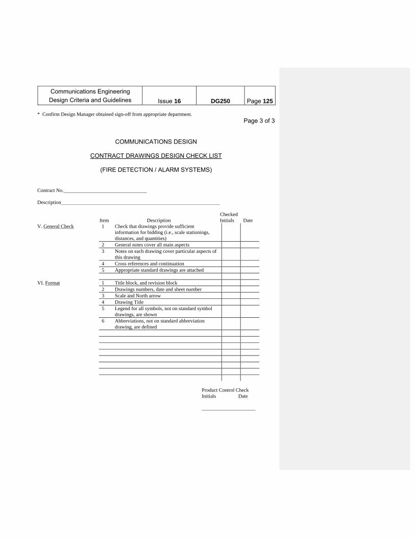
Communications Engineering
Design Criteria and Guidelines
Issue 16
DG250
Page 125
* Confirm Design Manager obtained sign-off from appropriate department. Page 3 of 3
COMMUNICATIONS DESIGN
CONTRACT DRAWINGS DESIGN CHECK LIST
(FIRE DETECTION / ALARM SYSTEMS) Contract No. Description Checked Item Description Initials Date V. General Check 1 Check that drawings provide sufficient
information for bidding (i.e., scale stationings, distances, and quantities)
2 General notes cover all main aspects 3 Notes on each drawing cover particular aspects of
this drawing
4 Cross references and continuation 5 Appropriate standard drawings are attached VI. Format 1 Title block, and revision block 2 Drawings numbers, date and sheet number 3 Scale and North arrow 4 Drawing Title 5 Legend for all symbols, not on standard symbol
drawings, are shown
6 Abbreviations, not on standard abbreviation drawing, are defined
Product Control Check Initials Date _____________________

Communications Engineering
Design Criteria and Guidelines
Issue 16
DG250
Page 126
Page 1 of 3
COMMUNICATIONS DESIGN
CONTRACT DRAWINGS DESIGN CHECK LIST VIII. (HP & SPEAKERPHONE SYSTEMS (ELEVATORS & AREA OF REFUGE) ,
Contract No. Description Checked Item Description Initials Date I. System Drawing (Key plan)
1 All components of system are shown - Review full functionality, check against layout drawings.
2 Interface with any other systems shown. 3 Satisfies scope requirements. 4 Satisfies user requirements. * 5 Satisfies operation/maintenance requirements.* 6 Satisfies Authority standards 7 Satisfies Code requirements (if applicable) 8 Monitoring agent booth location (s) shown II. Equipment 1 Sufficient capacity for system expansion. 2 Meets Authority standard 3 Meets operation/maintaining requirements. * 4 Meets user requirements. * 5 Outdoor equip. is weather resistant. Other equip. is
vandal resistant. as required.
6 Each type of intercom unit shown is suitable for its location.
7 New equipment is compatible with existing equipment (for expansion of existing system).
* Confirm Design Manager obtained sign-off from appropriate department. * In addition to this checklist, all design drawings are to be checked as per DG 107.

Communications Engineering
Design Criteria and Guidelines
Issue 16
DG250
Page 127
Page 2 of 3
COMMUNICATIONS DESIGN
CONTRACT DRAWINGS DESIGN CHECK LIST (HP & SPEAKERPHONE SYSTEMS (ELEVATORS & AREA OF REFUGE)
Contract No. Description Checked Item Description Initials Date III. Equipment and Cable Layout
1 Approximate location and layout of all cable and equipment are shown.
2 Location satisfies operation/maintenance requirements. *
3 Location satisfies user requirements. * 4 Location has approval of dept. having jurisdiction
over room. *
5 Cable and conduit layout do not interfere with modernization projects, other exist. equipment or architectural details of room.
6 Check for other Contracts in the area and coordinate.
7 Maintainability (Safety). * 8 Comm. Room size is adequate ( if applicable) 9 Speakerphone number/location for each unit is
indicated (cross check with system drawing)
10 Conduit runs comply with design guidelines. Approval by Station Clearing House.
11 Drawings indicate required signs, such as “Press for Assistance.”
12 Feature phone is provided for each full time booth. 13 Stations Department agrees to have required
equipment in each booth.
* Confirm Design Manager obtained sign-off from appropriate department.

Communications Engineering
Design Criteria and Guidelines
Issue 16
DG250
Page 128
Page 3 of 3 COMMUNICATIONS DESIGN
CONTRACT DRAWINGS DESIGN CHECK LIST
(HP & SPEAKERPHONE SYSTEMS (ELEVATORS & AREA OF REFUGE))
Contract No. Description Checked Item Description Initials Date IV. Wire & Cable 1 Size (AWG and # of pair) indicated. 2 Meets Authority standards (check with equipment
manufacturer for special cables).
3 Spare conductors available (if applicable). 4 Termination facilities in existing telephone
terminal boxes are available.
5 Cross connection to existing systems indicated as required.
6 Required AC power feeds are indicated. V. General Check 1 Check that drawings provide sufficient
information for bidding (i.e., scale, stationings, distances, and quantities).
2 General notes cover all main design aspects 3 Notes on each drawing pertain to the particular
aspects of that drawing.
4 Cross references and continuations. 5 Appropriate standard drawings are attached. VI. Format 1 Title block and revision block. 2 Dwg. numbers, date and sheet numbers 3 Scale and North arrow 4 Drawing Title. 5 Legend for all symbols, not on standard symbol
drawings, are shown.
6 Abbreviations, not on standard abbreviation drawings, are defined.
Product Control Check Initials Date ____________________
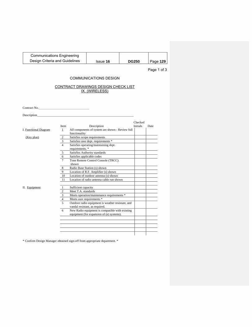
Communications Engineering
Design Criteria and Guidelines
Issue 16
DG250
Page 129
Page 1 of 3
COMMUNICATIONS DESIGN
CONTRACT DRAWINGS DESIGN CHECK LIST IX. (WIRELESS)
Contract No. Description Checked Item Description Initials Date I. Functional Diagram 1 All components of system are shown - Review full
functionality
(Key plan) 2 Satisfies scope requirements 3 Satisfies user dept. requirements * 4 Satisfies operating/maintaining dept.
requirements. *
5 Satisfies Authority standards 6 Satisfies applicable codes 7 Tone Remote Control Console (TRCC).
shown
8 Radio Base Station (s) shown 9 Location of R.F. Amplifier (s) shown 10 Location of outdoor antenna (s) shown 11 Location of radio antenna cable run shown II. Equipment 1 Sufficient capacity 2 Meet T.A. standards 3 Meets operation/maintenance requirements * 4 Meets user requirements * 5 Outdoor radio equipment is weather resistant, and
vandal resistant, as required.
6 New Radio equipment is compatible with existing equipment (for expansion of (e) systems).
* Confirm Design Manager obtained sign-off from appropriate department. *

Communications Engineering
Design Criteria and Guidelines
Issue 16
DG250
Page 130
Page 2 of 3
COMMUNICATIONS DESIGN
CONTRACT DRAWINGS DESIGN CHECK LIST (WIRELESS)
Contract No. Description Checked Item Description Initials Date III. Equipment and Cable Layout
1 Approximate location and layout of all cable and equipment are shown
2 Location satisfies operation/maintenance requirements. *
3 Location satisfies user requirements * 4 Location has approval of dept. having jurisdiction
over room and location satisfies requirement for coverage of voice quality.
5 Cable and conduit layout do not interfere with modernization projects, other existing equipment or architectural details of room
6 Check for other Contracts in the area and coordinate.
7 Maintainability (Safety) * 8 Communications/Radio Base Station Room size
Adequate.
9 Power sources indicated for remotely relocated devices.
10 Location of all power splitters (s), divider (s) and termination (s) shown.
IV. Wire & Cable 1 Size (AWG and # of pairs) 2 Meets T.A. standards 3 Spare requirements are met 4 Termination facilities in existing telephone
terminal boxes are available
5 Cross connection to existing systems are provided 6 Required AC power feeds are shown 7 Locate new splices in place of old splices for new
cable tails. Check nearest manhole in subway and outside when on structure or out in the open
8 Termination for radiating antenna cable 9 Locate new radiating cable connectors in place of
old connectors for new radiating antenna cable.
* Confirm Design Manager obtained sign-off from appropriate department

Communications Engineering
Design Criteria and Guidelines
Issue 16
DG250
Page 131
Page 3 of 3
COMMUNICATIONS DESIGN
CONTRACT DRAWINGS DESIGN CHECK LIST (WIRELESS)
Contract No. Description Checked Item Description Initials Date V. General Check 1 Check that drawings provide sufficient
information for bidding (i.e., scale stationings, distances, and quantities)
2 General notes cover all main aspects 3 Notes on each drawing cover particular aspects of
this drawing
4 Cross references and continuation 5 Appropriate standard drawings are attached VI. Format 1 Title block, and revision block 2 Drawing numbers, date and sheet number 3 Scale 4 Drawing Title 5 Legend for all symbols, not on standard symbol
drawings, are shown
6 Abbreviations, not on standard abbreviation drawing, are defined
Product Control Check Initials Date
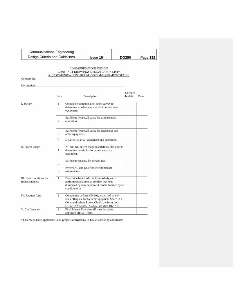
Communications Engineering
Design Criteria and Guidelines
Issue 16
DG250
Page 132
COMMUNICATIONS DESIGN
CONTRACT DRAWINGS DESIGN CHECK LIST* X. (COMMUNICATIONS ROOM SYSTEM/EQUIPMENT SPACE)
Contract No. Description Checked Item Description Initials Date I. Survey 1 Complete communication room survey to
determine whether space exists to install new equipment.
2
Sufficient floor/wall space for cabinets/rack allocation.
3
Sufficient floor/wall space for enclosures and other equipment.
4 Detailed list of all equipment and quantities.
II. Power Usage 1
AC and DC power usage calculations (designer to determine thresholds for power capacity upgrades).
2
Sufficient capacity for present use.
3
Power (AC and DC) fuse/circuit breaker assignments
III. Heat conditions for rooms/cabinets
1 Determine heat load conditions (designer to perform calculations to confirm that heat dissipated by new equipment can be handled by air conditioners).
IV. Request form 1 Completion of form OP-501, issue 1.02 or the latest ‘Request for System/Equipment Space in a Communications Room. Obtain the form from DOS, C&SE. (see, DG250, Part One, III, O. 9)
V. Confirmation 1 Final Master Plan sign-off sheet includes approved OP-501 form.
*This check list is applicable to all projects designed by in-house staff or by consultants
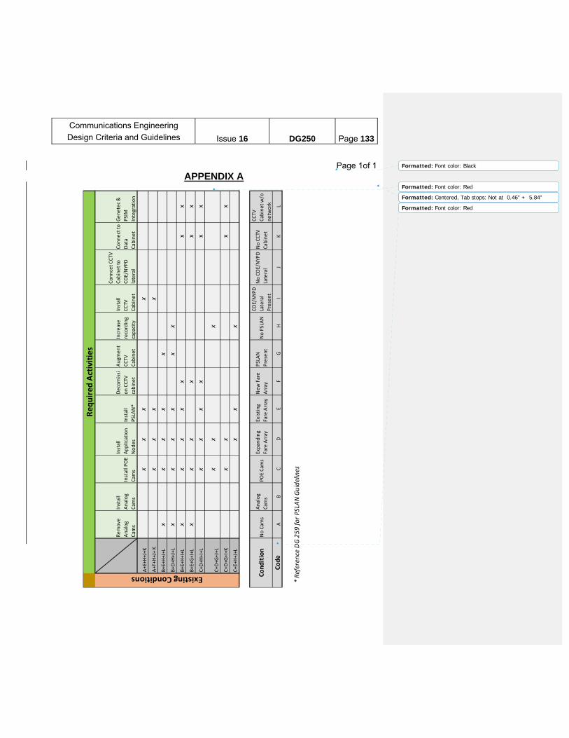
Communications Engineering
Design Criteria and Guidelines
Issue 16
DG250
Page 133
Page 1of 1
APPENDIX A
Remove
Analog
Cam
s
Install
Analog
Cam
s
Install POE
Cam
s
Install
Application
Nodes
Install
PSLAN*
Decomissi
on CCTV
cabinet
Augm
ent
CCTV
Cabinet
Increase
recording
capacity
Install
CCTV
Cabinet
Conncet CCTV
Cabinet to
COE/NYPD
lateral
Connect to
Data
Cabinet
Genetec &
PSIM
Integration
A+E+H
+J+K
xx
xx
A+F+H
+J+ K
xx
xx
B+E+H
+J+L
xx
xx
xB+D
+H+J+L
xx
xx
xx
B+E+H
+I+L
xx
xx
xx
x
B+E+G
+I+L
xx
xx
xx
C+D
+H+I+L
xx
xx
xx
C+D
+G+J+L
xx
x
C+D
+G+I+K
xx
xx
C+E+H
+J+L
xx
x
No Cam
sAnalog
Cam
sPOE Cam
sExpanding
Fare Array
Existing
Fare Array
New Fare
Array
PSLAN
Present
No PSLAN
COE/NYPD
Lateral
Present
No COE/NYPD
Lateral
No CCTV
Cabinet
CCTV
Cabinet w/o
netw
ork
AB
CD
EF
GH
IJ
KL
* Reference DG
259
for P
SLAN
Guidelines
Existing Conditions
Requ
ired Ac
tivities
Cond
ition
Code
Formatted: Font color: Black
Formatted: Font color: Red
Formatted: Centered, Tab stops: Not at 0.46" + 5.84"
Formatted: Font color: Red