DFT+U Study of Polaronic Conduction in Li O and Li CO ...
10
1 DFT+U Study of Polaronic Conduction in Li 2 O 2 and Li 2 CO 3 : 2 Implications for Li−Air Batteries 3 J. M. Garcia-Lastra,* ,† J. S. G. Myrdal, †,‡ R. Christensen, †,‡ K. S. Thygesen, † and T. Vegge ‡ 4 † Center for Atomic-scale Materials Design (CAMD), Department of Physics, Technical University of Denmark, Fysikvej 1, 2800 Kgs. 5 Lyngby, Denmark 6 ‡ Department of Energy Conversion and Storage, Technical University of Denmark, DK-4000 Roskilde, Denmark 7 ABSTRACT: The main discharge products formed at the 8 cathode of nonaqueous Li−air batteries are known to be Li 2 O 2 9 and residual Li 2 CO 3 . Recent experiments indicate that the 10 charge transport through these materials is the main limiting 11 factor for the battery performance. It has been also shown that 12 the performance of the battery decreases drastically when the 13 amount of Li 2 CO 3 at the cathode increases with respect to 14 Li 2 O 2 . In this work, we study the formation and transport of 15 hole and electron polarons in Li 2 O 2 and Li 2 CO 3 using density 16 functional theory (DFT) within the PBE+U approximation. 17 For both materials, we find that the formation of polarons (both hole and electron) is stabilized with respect to the delocalized 18 states for all physically relevant values of U. We find a much higher mobility for hole polarons than for the electron polarons, and 19 we show that the poor charge transport in Li 2 CO 3 compared to Li 2 O 2 can be understood through a polaronic model for the 20 conduction. Furthermore, the hole polaronic model in Li 2 O 2 provides a possible explanation for the experimentally observed 21 preferential growth direction of the films. Our results also suggest that doping is unlikely to be a viable route for improving the 22 transport properties of Li 2 O 2 or Li 2 CO 3 . 1. INTRODUCTION 23 The emission of greenhouse gases and the local pollution in the 24 cities produced by the fossil fuel-powered vehicles (FFVs) is 25 forcing the development of alternative power systems for 26 automobiles. Electric vehicles (EVs) represent one of the main 27 alternatives to the FFVs. 1 EVs eliminate the problem of the 28 local pollution. Additionally, the global issues involving 29 greenhouse gas emission could be reduced if the batteries of 30 the EVs were charged from a renewable energy source. 31 However, the present electric vehicles, powered by Li ion 32 batteries, are limited in power and range 1 because of the poor 33 gravimetric energy density of Li ion batteries, which is 1 order 34 of magnitude lower than that of gasoline (160 Wh/kg in the 35 former versus 1700 Wh/kg in the latter). 2−6 For this reason, 36 automakers have started to evaluate the possibility of using Li− 37 air batteries (LABs), which have a gravimetric energy density 38 similar to that of gasoline, for the propulsion of the EVs. 2−6 39 Di fferent architectures of LABs are currently being 40 investigated, each with their own challenges that must be 41 addressed before they can enter the market. 3,4,7,8 In this work, 42 we will focus on the nonaqueous LABs (NALABs) architecture. 43 A main challenge of NALABs is to overcome the so-called 44 “sudden death” process that takes place in the battery during 45 discharge. 9 During discharge of a NALAB, Li + ions from the 46 electrolyte and O 2 molecules from the air combine with 47 electrons provided by the cathode to form a Li 2 O 2 or Li 2 CO 3 48 solid film 9,10 (depending on the electrolyte of the battery). This 49 film is deposited on the surface of the cathode. During the 50 discharge process, the thickness of the film increases, and the 51 ability of electrons to move from the cathode to the 52 electrolyte−film interface becomes crucial. Li 2 O 2 and Li 2 CO 3 53 are both insulators with calculated band gaps of 4.9 10−12 and 54 8.8 eV, 10 respectively. Any electronic conduction through such 55 films would therefore have to be assisted by the presence of 56 dopants, defects, or polarons or by surface conductance. This 57 limited electronic conduction eventually becomes responsible 58 for the sudden death of the battery discharge. 59 The sudden death of NALABs has been extensively 60 investigated with a broad variety of experimental techniques, 4 61 trying to clarify the influence of the different components on 62 the performance of the battery. Particular attention has been 63 paid to the role of the electrolyte. It has been shown that the 64 main discharge product in the NALABs cathode is Li 2 CO 3 if a 65 carbonate-based electrolyte is used, 10,13 whereas Li 2 O 2 is mainly 66 formed with a non-carbonate-based electrolyte. 9,13 A Li 2 CO 3 67 monolayer may be also formed using a non-carbonate-based 68 electrolyte, due to the reaction between Li 2 O 2 and carbon from 69 the cathode. 14 It has been also shown that the performance 70 (capacity and cyclability) of the NALABs decreases drastically 71 when the amount of Li 2 CO 3 in the thin films at the cathode 72 increases with respect to the amount of Li 2 O 2 . 13 Received: October 31, 2012 Revised: February 14, 2013 Article pubs.acs.org/JPCC © XXXX American Chemical Society A dx.doi.org/10.1021/jp3107809 | J. Phys. Chem. C XXXX, XXX, XXX−XXX pubsdm_prod | ACSJCA | JCA10.0.1465/W Unicode | research.3f (R3.5.i1:3915 | 2.0 alpha 39) 2012/12/04 10:21:00 | PROD-JCA1 | rq_1096795 | 2/22/2013 07:14:09 | 10
Transcript of DFT+U Study of Polaronic Conduction in Li O and Li CO ...

1 DFT+U Study of Polaronic Conduction in Li2O2 and Li2CO3:2 Implications for Li−Air Batteries3 J. M. Garcia-Lastra,*,† J. S. G. Myrdal,†,‡ R. Christensen,†,‡ K. S. Thygesen,† and T. Vegge‡
4†Center for Atomic-scale Materials Design (CAMD), Department of Physics, Technical University of Denmark, Fysikvej 1, 2800 Kgs.
5 Lyngby, Denmark
6‡Department of Energy Conversion and Storage, Technical University of Denmark, DK-4000 Roskilde, Denmark
7 ABSTRACT: The main discharge products formed at the8 cathode of nonaqueous Li−air batteries are known to be Li2O29 and residual Li2CO3. Recent experiments indicate that the10 charge transport through these materials is the main limiting11 factor for the battery performance. It has been also shown that12 the performance of the battery decreases drastically when the13 amount of Li2CO3 at the cathode increases with respect to14 Li2O2. In this work, we study the formation and transport of15 hole and electron polarons in Li2O2 and Li2CO3 using density16 functional theory (DFT) within the PBE+U approximation.17 For both materials, we find that the formation of polarons (both hole and electron) is stabilized with respect to the delocalized18 states for all physically relevant values of U. We find a much higher mobility for hole polarons than for the electron polarons, and19 we show that the poor charge transport in Li2CO3 compared to Li2O2 can be understood through a polaronic model for the20 conduction. Furthermore, the hole polaronic model in Li2O2 provides a possible explanation for the experimentally observed21 preferential growth direction of the films. Our results also suggest that doping is unlikely to be a viable route for improving the22 transport properties of Li2O2 or Li2CO3.
1. INTRODUCTION
23 The emission of greenhouse gases and the local pollution in the24 cities produced by the fossil fuel-powered vehicles (FFVs) is25 forcing the development of alternative power systems for26 automobiles. Electric vehicles (EVs) represent one of the main27 alternatives to the FFVs.1 EVs eliminate the problem of the28 local pollution. Additionally, the global issues involving29 greenhouse gas emission could be reduced if the batteries of30 the EVs were charged from a renewable energy source.31 However, the present electric vehicles, powered by Li ion32 batteries, are limited in power and range1 because of the poor33 gravimetric energy density of Li ion batteries, which is 1 order34 of magnitude lower than that of gasoline (160 Wh/kg in the35 former versus 1700 Wh/kg in the latter).2−6 For this reason,36 automakers have started to evaluate the possibility of using Li−37 air batteries (LABs), which have a gravimetric energy density38 similar to that of gasoline, for the propulsion of the EVs.2−6
39 Different architectures of LABs are currently being40 investigated, each with their own challenges that must be41 addressed before they can enter the market.3,4,7,8 In this work,42 we will focus on the nonaqueous LABs (NALABs) architecture.43 A main challenge of NALABs is to overcome the so-called44 “sudden death” process that takes place in the battery during45 discharge.9 During discharge of a NALAB, Li+ ions from the46 electrolyte and O2 molecules from the air combine with47 electrons provided by the cathode to form a Li2O2 or Li2CO3
48 solid film9,10 (depending on the electrolyte of the battery). This49 film is deposited on the surface of the cathode. During the
50discharge process, the thickness of the film increases, and the51ability of electrons to move from the cathode to the52electrolyte−film interface becomes crucial. Li2O2 and Li2CO3
53are both insulators with calculated band gaps of 4.910−12 and548.8 eV,10 respectively. Any electronic conduction through such55films would therefore have to be assisted by the presence of56dopants, defects, or polarons or by surface conductance. This57limited electronic conduction eventually becomes responsible58for the sudden death of the battery discharge.59The sudden death of NALABs has been extensively60investigated with a broad variety of experimental techniques,4
61trying to clarify the influence of the different components on62the performance of the battery. Particular attention has been63paid to the role of the electrolyte. It has been shown that the64main discharge product in the NALABs cathode is Li2CO3 if a65carbonate-based electrolyte is used,10,13 whereas Li2O2 is mainly66formed with a non-carbonate-based electrolyte.9,13 A Li2CO3
67monolayer may be also formed using a non-carbonate-based68electrolyte, due to the reaction between Li2O2 and carbon from69the cathode.14 It has been also shown that the performance70(capacity and cyclability) of the NALABs decreases drastically71when the amount of Li2CO3 in the thin films at the cathode72increases with respect to the amount of Li2O2.
13
Received: October 31, 2012Revised: February 14, 2013
Article
pubs.acs.org/JPCC
© XXXX American Chemical Society A dx.doi.org/10.1021/jp3107809 | J. Phys. Chem. C XXXX, XXX, XXX−XXX
pubsdm_prod | ACSJCA | JCA10.0.1465/W Unicode | research.3f (R3.5.i1:3915 | 2.0 alpha 39) 2012/12/04 10:21:00 | PROD-JCA1 | rq_1096795 | 2/22/2013 07:14:09 | 10

73 One of the purposes of the present work is precisely to74 understand the poor performance of the electronic conduction75 mechanism in Li2CO3 compared to that of Li2O2, using density76 functional theory (DFT) within the PBE+U (Perdew−Burke−77 Ernzerhof functional15 with Hubbard correction16−18) approx-78 imation.79 As mentioned, both Li2CO3 and Li2O2 are wide gap80 insulators. There have been several proposals for the81 mechanism of electron transport across thin films of these82 materials. DFT-PBE and G0W0 calculations by Hummelshoj et83 al. for Li2O2 have shown that presence of Li vacancies produces84 holes in the valence band, pointing to bandlike surface or bulk85 transport mechanism in such naturally p-doped Li2O2.
11
86 However, more recent calculations by Ong et al., using the87 Heyd−Scuseria−Ernzerhof19 (HSE) hybrid functional, predict88 that the hole created by the Li vacancy prefers to localize at the89 vacancy and hence invalidate a bandlike transport mechanism90 in the bulk.20 It is well-known that the PBE functional, as the91 rest of the general gradient approximations (GGA), suffers92 from a Coulombic self-interaction error, which tends to93 delocalize electrons (and holes).21 Hybrid functionals, such as94 HSE and the PBE+U approximation used in the present work,95 reduce the self-interaction error and consequently provide96 more realistic description of localized electronic states.20,21
97 Another recent PBE study by Radin et al. points to the98 metallization of the Li2O2 surface as a possible mechanism for99 charge transport, although no experimental measurement of the100 surface conductivity of Li2O2 has been yet reported.22 Flat101 glassy carbon experiments have shown that the thickness of the102 Li2O2 film formed in the cathode can be less than 5 nm when103 the sudden death occurs.9 Combined DFT and nonequilibrium104 Green function calculations indicate that electron tunneling105 could contribute significantly to the electron conductivity for106 such small thicknesses.9 Finally, a polaronic electron (ref 23)107 and hole (ref 20) hopping mechanism has been suggested for108 bulk Li2O2. Specifically, DFT-HSE calculations by Kang et al.109 showed that an electron added to Li2O2 spontaneously localizes110 at an O2
2− peroxide ion. Moreover, the barrier for moving the111 extra electron between neighboring ions is low enough that112 electron hopping can take place at room temperature.23 A very113 similar study by Ong et al. showed that electronic holes also114 localize spontaneously on the O2
2− peroxide ions with hopping115 barriers even lower than that of electron polarons.20 Radin et al.116 have also proposed surface polarons as a possible mechanism117 for electronic conduction in Li2O2.
24
118 In the present work, we revisit the polaronic conduction119 mechanism in Li2O2 using PBE+U calculations and extend the120 study to Li2CO3 for which polaron formation and transport has121 not previously been explored. To obtain the key microscopic122 parameter for our model, namely the barrier for polaron123 hopping, we perform a systematic study of the electronic124 localization and barrier heights as a function of the Hubbard U125 describing the Coulomb interaction on the O 2p orbitals in the126 PBE+U scheme. We show that hole polaron mobility is much127 higher than the one of electron polarons in both Li2O2 and128 Li2CO3 and show that the poor conductivity of Li2CO3 in129 comparison with Li2O2 can be understood within a polaronic130 model.131 The paper is organized as follows. In section 2, the132 computational methods and the structures of Li2O2 and133 Li2CO3 are described. The main results of the PBE+U134 calculations for polaron stability and barriers are outlined in
135section 3. Polaronic conduction is discussed in section 4. Some136final remarks are given in section 5.
2. LI2O2 AND LI2CO3 STRUCTURES AND137COMPUTATIONAL METHODS138Experimentally, Li2O2 is found to crystallize in a hexagonal139structure with lattice parameters a = b = 3.187 Å, c = 7.726 Å140 f1(space group P63/mmc, see Figure 1a).25 Previous DFT
141calculations have reported that the reconstructed [11 ̅00]142surface is the most stable.11,22 Subsequent work has shown143that a number other facets have similar surface energies and will144likely also be exposed, i.e., [0001] and [11 ̅20],22,24 and recent145work by Hummelshoj et al.26 has shown that these terminations146will depend on potential and can be different under charge and147discharge conditions.148Li2CO3 crystallizes in a monoclinic structure with lattice149parameters a = 8.359 Å, b = 4.972 Å, c = 6.197 Å, and β =150 f2114.83° (space group 15; see Figure 2a).27 According to DFT151calculations, the most stable surface of Li2CO3 is the [001].28
152As previously noted,12 Li2O2 can be viewed as a molecular153solid formed by independent peroxide O2
2− ions in a sea of Li+
154ions. Indeed, the valence and conduction bands of Li2O2 are155almost completely formed by the O2
2− frontier orbitals (see156Figure 1b) with a negligible contribution from the Li+
157orbitals.12 In the case of Li2CO3, the picture is very similar.158This material can be visualized as a molecular solid formed by159independent carbonate CO3
2− ions, embedded in a sea of Li+
160ions. The band gap of Li2CO3 (8.8 eV) is much larger than that161of Li2O2 (4.9 eV) because the gap between the highest162occupied molecular orbital (HOMO) and the lowest163unoccupied molecular orbital (LUMO) of CO3
2− is corre-164spondingly larger than that of the O2
2− ion.29
165We have studied the localization of holes and electrons using166the DFT+U methodology, which has been described in depth167in the literature.17,18 DFT+U has been extensively used in the168study of transition metal oxides where the U correction30 is169typically applied to the d orbitals of the transition170metal.18,21,31−33 In our case, we have applied the U correction
Figure 1. (a) Unit cell of Li2O2 repeated twice along the [100]direction. Lattice parameters a = b = 3.187 Å, and c = 7.725 Å. Theintralayer (red arrow) and interlayer (blue arrow) paths for thepolaron hoping are also shown. (b) Structure and frontier orbitals ofthe O2
2− peroxide ion.
The Journal of Physical Chemistry C Article
dx.doi.org/10.1021/jp3107809 | J. Phys. Chem. C XXXX, XXX, XXX−XXXB
171 to the oxygen 2p orbitals and the carbon 2p orbitals (in the case172 of Li2CO3), since these are the orbitals which form the frontier173 bands of Li2O2 and Li2CO3 (see Figures 1b and 2b). We have174 tracked the U-dependence of the localization properties by175 varying the U parameter from 0 to 8 eV. For simplicity, we have176 applied the same U corrections to oxygen and carbon atoms in177 the case of Li2CO3. Previous theoretical studies of other178 systems containing O 2p holes (magnesia with Mg vacancies or179 N dopants, and silica doped with Al) have found that the U180 value that best reproduced experimental findings was in the181 range of U ∼ 5−7 eV.34−37 Additionally, Auger spectroscopy182 experiments showed that the on-site Coulomb repulsion energy183 (analogous of the U value) for a hole in an O 2p state is also in184 the range of 5−7 eV.38,39 In a recent study of C-doped AlN, Li185 et al. applied a U = 5.6 eV correction to the C 2p state.40
186 Similar +U corrections for 2p states of other elements can be187 found in the literature.41
188 All calculations have been performed with the real space189 GPAW code.42 The exchange-correlation energy has been190 computed with the PBE functional. We used a grid spacing of191 0.18 Å for the wave functions. No smearing has been applied192 for the occupation of the electronic states. The structures have193 been relaxed for each U value until a maximum force of <0.03194 eV/Å was obtained. For Li2O2, we have used a 4 × 4 × 2195 supercell (256 atoms) and a k-point grid reduced to just the Γ196 point. For Li2CO3 we have used a 1 × 2 × 2 supercell (96197 atoms) with a 2 × 2 × 2 k-point grid. The formation of hole198 (electron) polarons has been studied by adding one hole199 (electron) to the supercell. In both cases the supercell was kept200 neutral by adding a uniform compensation charge.201 For all the U values where hole/electron polarons are found202 to exist, i.e., where an electronic state localizes around a lattice203 distortion, we have computed the migration barrier of the204 polarons. The barriers for the hopping of the polarons from205 one peroxide/carbonate ion to an adjacent ion have been206 calculated using the nudged elastic band method.43 In the case207 of Li2O2 there are two inequivalent paths between neighboring208 ions here referred to as intralayer and interlayer hops (see209 Figure 1a). In Li2CO3 there are three inequivalent paths210 referred to as intracolumn and intercolumn 1 and 2,211 respectively (see Figure 2a).
212In order to corroborate the formation of localized polarons,213we have repeated the calculations for Li2CO3 using the HSE214functional (equivalent calculations for Li2O2 are presented in215refs 20 and 23). These calculations were performed with the216Vienna Ab initio Simulation Package (VASP)44 within the217projector augmented-wave approach.45 The k-point grid was218reduced to just the Γ point with a plane-wave energy cutoff of219600 eV. HSE results show that the localized states are more220 t1stable than the delocalized ones (see Table 1), for both holes221and excess electrons, in good agreement with the PBE+U222calculation with physically relevant values of U (vide infra).
3. POLARON FORMATION ENERGIES AND223MIGRATION BARRIERS FROM DFT+U224In this section we discuss the results of PBE+U calculations for225the polaron formation energies and migration barriers in Li2O2226and Li2CO3 with the U correction applied to the O 2p and C2272p orbitals. Previous studies of oxygen containing compounds228have found an optimal U value in the range 5−7 eV using229various techniques.34−39 However, we have calculated all230relevant quantities, in particular the polaron migration barriers,231for U values in the range 0−8 eV. After a brief discussion of the232band gaps obtained with the PBE+U scheme, we describe the233nature of the localized states (holes and electrons) in the two234materials. For this presentation we use U = 6 eV since this is235the central value of the optimal U value range. Finally, the U-236dependence of the polaron formation energies and migration237barriers is discussed.238The calculated single-particle (Kohn−Sham) band gap is239found to vary linearly with U for both materials (the slopes are2400.48 and 0.44 for Li2O2 and Li2CO3, respectively; see the inset241 f3f4in Figures 3a and 4a). Similar dependencies have been found242for chromia32 and titania,21 and agreement with the G0W0243calculated band gap is obtained for U = 6 eV and U = 8 eV for244Li2O2 and Li2CO3, respectively. It should, however, be noted245that the calculated band gap should not be used to fit the value246of U, since the Kohn−Sham band gap is not equal to the true247band gap even when the exact exchange-correlation functional248is used. In contrast, the polaron formation energies and249migration barriers evaluated in the following are based on total250energy differences and are thus more adequate quantities for251the determination of the optimal U value.
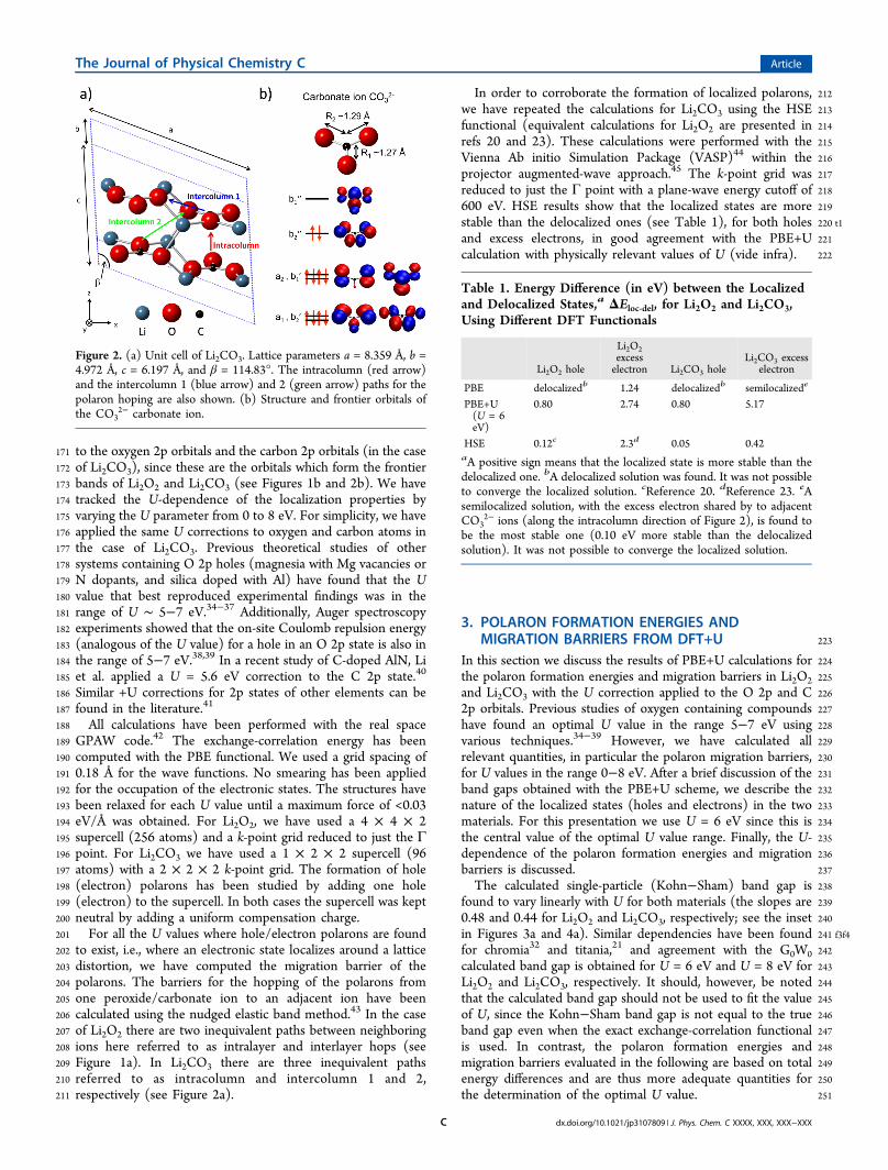
Figure 2. (a) Unit cell of Li2CO3. Lattice parameters a = 8.359 Å, b =4.972 Å, c = 6.197 Å, and β = 114.83°. The intracolumn (red arrow)and the intercolumn 1 (blue arrow) and 2 (green arrow) paths for thepolaron hoping are also shown. (b) Structure and frontier orbitals ofthe CO3
2− carbonate ion.
Table 1. Energy Difference (in eV) between the Localizedand Delocalized States,a ΔEloc‑del, for Li2O2 and Li2CO3,Using Different DFT Functionals
Li2O2 hole
Li2O2excesselectron Li2CO3 hole
Li2CO3 excesselectron
PBE delocalizedb 1.24 delocalizedb semilocalizede
PBE+U(U = 6eV)
0.80 2.74 0.80 5.17
HSE 0.12c 2.3d 0.05 0.42aA positive sign means that the localized state is more stable than thedelocalized one. bA delocalized solution was found. It was not possibleto converge the localized solution. cReference 20. dReference 23. eAsemilocalized solution, with the excess electron shared by to adjacentCO3
2− ions (along the intracolumn direction of Figure 2), is found tobe the most stable one (0.10 eV more stable than the delocalizedsolution). It was not possible to converge the localized solution.
The Journal of Physical Chemistry C Article
dx.doi.org/10.1021/jp3107809 | J. Phys. Chem. C XXXX, XXX, XXX−XXXC

252 In Li2O2 we find that a hole localizes on one of the O22−
253 peroxide ions which thereby becomes an O2− superoxide ion.
254 There are three fingerprints of the localization, namely, as255 follows. (i) The O−O distance of the O2 molecule at which the256 hole is localized is reduced from 1.52 to 1.32 Å. The latter is the257 typical distance of a superoxide O2
− ion.25 (ii) The analysis of258 the magnetic moments reveals that a magnetic moment of μ =259 1 μb forms at the contracted O2 molecule, while it remains zero260 everywhere else in the supercell. (iii) The density of states261 (DOS) of the system (Figure 3a) shows an empty state262 between the valence band (VB) and the conduction band263 (CB). For U = 6 eV this empty state is 2 eV above the VB (the264 position changes with U). The character of this empty state265 corresponds to the π*g antibonding orbital of the O2 unit on266 which the hole is localized. This is also the character of the267 HOMO of a peroxide ion (see Figure 1b). Similar features for268 the localization of holes in Li2O2 were found by Ong et al. using269 the HSE functional.20
270 In the case of the electron polaron in Li2O2, the excess271 electron is also localized on one of the O2
2− peroxide ions,272 occupying its LUMO orbital. In this way this peroxide ion273 becomes an O2
3− ion. The occupation of the LUMO is274 reflected in the DOS of the system (Figure 3b), where a peak275 positioned 3.3 eV below the bottom of the CB appears. This276 has two important consequences: (i) The O−O distance of the277 O2 molecule at which the electron is localized increases from
2781.52 to 2.18 Å. This is due to the strong antibonding character279of the LUMO orbital (it is a σ*u orbital; see Figure 1b). (ii) A280magnetic moment of μ = 1 μb appears at the elongated O2281molecule, while it remains zero everywhere else in the supercell.282Kang et al., using the HSE functional, reported an analogous283behavior for the localization of excess electrons in Li2O2.
23
284Before moving to the localization of electrons and holes in285Li2CO3, we summarize a few properties of the CO3
2− carbonate286ion. CO3
2− consists of a carbon atom surrounded by three287oxygen atoms with the same C−O distance in a trigonal planar288arrangement with D3h molecular symmetry. In Li2CO3, the289molecular symmetry of the CO3
2− ions is reduced to C2v due to290the presence of the Li+ ions. In this environment one of the291three oxygen atoms is slightly closer to the central carbon atom292than the other two (we label the shorter C−O distance as R1293and the longer ones as R2; see Figure 2b). The frontier orbitals294of the CO3
2− ion are shown in Figure 2b. The LUMO is an295antibonding orbital between the pz orbital of the carbon atom296and the pz orbitals of the three oxygen atoms, and has a297significantly larger contribution from the carbon atom than298from the oxygen atoms. The HOMO and the rest of the299occupied frontier orbitals are antibonding combinations of the300p orbitals of the oxygen atoms, with no component from the301carbon atom.302The hole in Li2CO3 occupies the HOMO of one CO3
2−
303carbonate ion which thereby becomes a CO3− ion, while the
304rest of the CO32− ions in the supercell remain unaltered. As a
Figure 3. Calculated densities of states (DOS), using PBE+U with U =6 eV, for a 4 × 4 × 2 Li2O2 supercell containing (a) an electronic holeand (b) an extra electron. The blue dashed curves correspond to thespin majority channel and the red solid curve to the spin minoritychannel. The energies are given with respect to the top of the valence.The Fermi levels are indicated with the vertical black dashed lines. Thedependence of the band gap upon the U value is shown in the inset ofpanel a.
Figure 4. Calculated densities of states (DOS), using PBE+U with U =6 eV, for a 1 × 2 × 2 Li2CO3 supercell containing (a) an electronichole and (b) an extra electron. The blue dashed curves correspond tothe spin majority channel and the red solid curve to the spin minoritychannel. The energies are given with respect to the top of the valence.The Fermi levels are indicated with the vertical black dashed lines. Thedependence of the band gap upon the U value is shown in the inset ofpanel a.
The Journal of Physical Chemistry C Article
dx.doi.org/10.1021/jp3107809 | J. Phys. Chem. C XXXX, XXX, XXX−XXXD

305 consequence, a magnetic moment of μ = 1 μb emerges on the306 CO3
− ion whose structure is distorted with respect to that of307 CO3
2−. Namely, R1 is enlarged by 0.11 Å while R2 is reduced by308 0.07 Å. This could seem surprising since after removing one309 electron from the HOMO (which is an antibonding orbital) a310 shortening of the three C−O distances would be expected. The311 different behavior of the oxygen atom at R1 (from here on312 denoted O1) with respect to the oxygen atoms at R2 (from here313 on denoted O2) is due to the relaxation of the Li+ ions314 surrounding the CO3
− ions. Li+ ions close to O1 move away315 from the CO3
− ion by 0.38 Å on average, while Li+ ions close to316 O2 only move away by 0.17 Å. The localized hole on the CO3
−
317 ion can be seen in the Li2CO3 DOS as a peak located 2.2 eV318 above the top of the VB (this value varies for other values of U319 different than U = 6 eV).320 In the case of the electron polaron in Li2CO3, the excess321 electron occupies the LUMO of one of the CO3
2− ions which
322thereby becomes a CO33− ion. Subsequently, a magnetic
323moment of μ = 1 μb appears on the CO33− ion (mainly
324localized on the carbon atom). The corresponding peak for this325excess electron is situated 7.3 eV below the bottom of the CB326(see the DOS in Figure 4b). Both R1 and R2 of the CO3
3− ion327increase by 0.11 Å with respect to CO3
2−.328Next, we examine the dependence of the localization on U.329Previous studies have shown that the localization of holes and330electrons depends on the chosen value of U,21,34−37 with331localization favored for higher U values. One example is the332localization of holes in Al-doped silica studied by Nolan and333Watson.35 Experimentally, an O 2p hole in SiO2:Al
3+ was334detected by means of electron paramagnetic resonance335(EPR).46 In order to reproduce a localized hole it was found336that U values above 6 eV were required. Returning to our337 f5f6calculations, the insets of Figures 5 and 6 show the variation of338the total energy difference between the localized and the
Figure 5. Calculated total energy along the intralayer (blue circles) and interlayer (red squares) hopping paths in a 4 × 4 × 2 Li2O2 supercell using U= 6 eV for (a) a hole polaron and (b) an electron polaron. The energies of the delocalized states are shown as a reference. The dependences of theheight of the barriers, EB, and the energy difference between the localized and delocalized states, ΔEloc‑del, upon the U value are shown in the inset ofpanel b.
The Journal of Physical Chemistry C Article
dx.doi.org/10.1021/jp3107809 | J. Phys. Chem. C XXXX, XXX, XXX−XXXE

339 delocalized solutions, ΔEloc‑del, as a function of U.47 For holes in
340 Li2O2 we have found that the localized solution is the most341 stable for U ≥ 3 eV. As for the band gaps, we find that ΔEloc‑del
342 increases linearly with U (Figure 5a). In the case of the excess343 electron in Li2O2 the localized solution is more stable than the344 delocalized for all U values and ΔEloc‑del is again linearly345 dependent on U (Figure 5b). The threshold for the localization346 of holes in Li2CO3 is at U ≥ 5 eV (Figure 6a), slightly higher347 than in Li2O2. Likewise in Li2O2, there is a linear dependence of348 ΔEloc‑del with U (Figure 6a). The excess electron in Li2CO3, as349 in Li2O2, is localized for all the U values. However, for U ≤ 1350 eV the excess electron is localized in two adjacent carbonate351 ions, instead of only in one. Another peculiarity of the excess352 electrons in Li2CO3 is that ΔEloc‑del grows quadratically with U353 rather than linearly (Figure 6b). This is related with the strong354 C2p character of the LUMO level of the CO3
2− carbonate ion355 (Figure 2b). In Li2O2 holes and excess electrons are localized in356 orbitals with O2p character, as it happens with the holes in
357Li2CO3 (HOMO of CO32− carbonate ion does not have any
358C2p weight). Thus, only the U correction on the O2p level359affects the results. On the contrary, the results for the excess360electron in Li2CO3 are mainly dominated by the U correction361on the C2p level. This shows that the dependence of ΔEloc‑del on362U is linear if the Hubbard correction is applied to the O2p level363and quadratic if it is applied to the C2p level.364From our study of the degree of localization for different U365values, we can conclude that the excess electrons are easier to366localize than the holes and that the localization is slightly367stronger in Li2O2 than in Li2CO3. At the same time, we observe368that in the range from U = 5 to 7 eV (which is the optimal369range found in previous theoretical and experimental works),370the localized solutions are preferred in all the cases.371We next consider the barrier for moving the electron and372hole polarons between neighboring sites. A common feature for373all the studied migration paths is that the height of the barriers,374EB, increases linearly with U (Figures 5 and 6). As before, we
Figure 6. Calculated total energy along the intralayer (blue circles) and interlayer (red squares) hoping paths in a 1 × 2 × 2 Li2CO3 supercell usingU = 6 eV for (a) a hole polaron and (b) an electron polaron. The energies of the delocalized states are shown as a reference. The dependences of theheight of the barriers, EB, and the energy difference between the localized and delocalized states, ΔEloc‑del, upon the U value are shown in the inset ofpanel b.
The Journal of Physical Chemistry C Article
dx.doi.org/10.1021/jp3107809 | J. Phys. Chem. C XXXX, XXX, XXX−XXXF

375 will focus our analysis on the results for U = 6 eV. In the case of376 a hole in Li2O2, we find that the barrier for the intralayer377 hopping, EB
intra = 0.385 eV, is 0.092 eV lower than the interlayer378 barrier, EB
inter = 0.477 eV (the difference stays roughly constant379 for all U values). This difference is similar to the one found by380 Ong et al. using the HSE functional (0.084 eV).20 It can be381 understood why EB
intra < EBinter by plotting the hole at the
382 transition state, i.e., at the top of the energy barrier. At this383 point, the hole occupies the bonding combination of the384 HOMOs of the two peroxide ions. Since the HOMO of the385 peroxide ion has a px (or py) character (see Figure 1b) the386 overlap at the transition state between the HOMOs is larger for387 the intralayer than the interlayer path, making the former more388 stable. In the case of an excess electron in Li2O2, EB
inter = 1.408389 eV is lower than EB
intra = 1.472 by 0.064 eV at U = 6 eV (the390 difference is similar for other U values). Kang et al., using the391 HSE functional, also reported EB
inter < EBintra (by 0.12 eV). The
392 excess electron at the transition state is located in an orbital393 which is the (linear) bonding combination of the LUMOs of394 two adjacent peroxide ions. Due to the pz character of the395 LUMO (see Figure 1b) the overlap is now larger for the396 interlayer configuration than for the intralayer one, making the397 transition state more stable in the case of the interlayer398 hopping.399 In the case of Li2CO3, the overlap between the orbitals of400 two adjacent carbonate ions is much smaller in comparison401 with those between peroxide ions in Li2O2. For this reason, EB402 is practically the same for all the different hopping paths (see403 Figure 6), e.g., EB = 0.55 eV for holes and EB = 1.05 eV for404 excess electrons at U = 6 eV. One common feature between405 Li2O2 and Li2CO3 is that the barriers for the hole polaron406 hopping are significantly smaller than the ones for the electron407 polaron. We also observe that, for U = 6 eV, EB is larger in408 Li2CO3 than in Li2O2 for all the paths studied. It is important to409 notice that EB is always significantly smaller than ΔEloc‑del such410 that the polaron stays localized during the entire hopping411 process.
4. POLARONIC CONDUCTION IN LI2O2 AND LI2CO3
412 The key ingredient to estimate the mobility of a polaron is the413 size of the migration barrier, EB, which determines the time for
414a polaron hop between two adjacent ions, τ. One possible way415to estimate τ is Marcus theory, which has been widely used by416chemists to model charge-transfer reactions, and which takes417nonadiabatic effects into account.48 In order to obtain τ from418Marcus theory, one must calculate the electron coupling and419the reorganization energy. The former can be easily estimated.420However, the calculation of the reorganization energy is a421cumbersome task in solids, and for this reason we will use, as a422first step, the simpler transition state theory (TST) to423determine τ. By using TST we have assumed that the polaron424hopping is an adiabatic process. For Li2O2 the adiabatic425assumption is well justified because the highest occupied orbital426at the transition state (the HOMO−HOMO bonding orbital427for the holes and the LUMO−LUMO bonding orbital for428excess electrons described in section 3) is well separated from429the lowest unoccupied orbital at the transition state. The gap430between bonding and antibonding HOMO−HOMO orbitals at431the transition state for holes, Δ, in Li2O2 is Δ = 0.65 eV at U =4326 eV. In the case of Li2CO3, Δ is only 0.1 eV for holes at U = 6433 f7eV (see Figure 7), and nonadiabatic effects could slow down434the hopping process.48
435Within TST, τ can be written
τω
ωω
= =∏∏
⎛⎝⎜
⎞⎠⎟
⎛⎝⎜
⎞⎠⎟
Ek T
Ek T
1exp exp
eff
B
b
TS
IS
B
b 436(1.1)
437where ωeff is a prefactor calculated within the harmonic TST,49
438kb is the Boltzmann constant, and T is the temperature. We439have calculated ωeff to be 1.46 × 10¹³ Hz (for a hole in Li2O2),4401.96 × 1013 Hz (for an excess electron in Li2O2), 4.47 × 10¹³
441Hz (for a hole in Li2CO3), and 2.16 × 10¹³ Hz (for an excess442electron in Li2CO3).443We note that ωeff is larger for Li2CO3 than for Li2O2 in444agreement with the fact that ground-state vibrational445frequencies of the carbonate ion are higher than those of the446peroxide ion.50 Using these ωeff and the EB at U = 6 eV from447the previous section, we can see that time for a hop at room448temperature (RT = 300 K) is several orders of magnitude larger449for electron polarons than for hole polarons in both Li2CO3450and Li2O2. Therefore, it is clear that any kind of charge451transport through a polaronic mechanism in these materials is452governed by the mobility of hole polarons rather than electron
Figure 7. Adiabatic potential energy surfaces of the ground (blue line) and the first excited (red line) states (a) for a hole polaron along the intralayerhoping path in Li2O2 and (b) for a hole polaron along the intracolumn hoping path in Li2CO3. The wave functions of the holes at the initial and finalconfigurations are shown for the ground state. The wave functions of the holes at the transition state configuration are shown for both the groundand the first excited states. The dashed black lines represent the nonadiabatic limit (i.e., no coupling between the wave functions of the initial and thefinal configurations at the transition state configuration).
The Journal of Physical Chemistry C Article
dx.doi.org/10.1021/jp3107809 | J. Phys. Chem. C XXXX, XXX, XXX−XXXG

453 polarons if both are present. Furthermore, we can also see that454 the time for a hop of a hole polaron at RT is 200 times smaller455 in Li2O2 than in Li2CO3. Within a hole polaron model for the456 conduction, we can therefore rationalize why the performance457 of NALABs is much poorer when Li2CO3 is formed at the458 cathode instead of Li2O2.459 In the case of Li2O2, the hole polaronic model can also help460 to explain how the thin films grow on the cathode of the461 NALABs. Transmission electron microscopy (TEM) images by462 Mitchell et al. of the Li−O2 discharge on high surface area all-463 carbon-nanofiber electrodes show formation of <400 nm464 toroidal Li2O2 particles at intermediate galvanostatic discharge465 (e.g., 1880 mAh/gC at 64 mA/gC).51 The same authors have466 recently performed high resolution TEM which shows the467 toroidal particles consist of a series of stacked Li2O2 platelets468 with a highly uniform size and shape. Under the applied469 discharge conditions, i.e., current density and temperature, in470 dimethoxyethane, the platelets reach a thickness of ∼5 nm in471 the ⟨0001⟩ directions and a “radius” of <200 nm in the ⟨11 ̅00⟩472 directions.52
473 It is possible to account for this characteristic growth from a474 simple picture combining the hole-based tunneling in the475 ⟨11 ̅00⟩9,33 directions and the hole polaronic transport476 mechanism described here. Once the layer exceeds a critical477 thickness, depending on the discharge current density, where478 tunneling becomes limiting for discharge (at ∼5 nm [11̅00] at 1479 μA/cm2),9 alternate conductions channels/mechanisms are480 needed.481 As discussed in the previous section for the hole polaron in482 Li2O2, the barriers are 0.09 eV lower in the intralayer case than483 in the interlayer one. At RT, this gives 30 times faster hole484 polaron conduction in the directions perpendicular to [0001],485 which would facilitate preferential growth in the intralayer486 directions, e.g., [11̅00], explaining the large radius of the487 platelets along this direction. The specific size and aspect ratio488 of the platelets should thus depend on both the discharge489 current density, the number of nucleation sites, and temper-490 ature. It is important to note that this could not account for an491 exponential drop-off in the discharge voltage, but the toroidal492 discharge products are also found to be dominated by growth493 of monolithic Li2O2 instead of particles in the sudden death494 regime51
495 Alternatively, a combination of surface conduction as496 originally discussed in refs 11, 22, and 24 and tunneling may497 also explain the toroidal growth.53 Experimental investigations498 of whether the aspect ratio is temperature dependent would499 resolve whether the polaronic conduction is dominant, but500 further work is needed to clarify this.
5. CONCLUSIONS501 We have shown by means of PBE+U calculations that both hole502 and excess electron polarons are localized in Li2O2 and Li2CO3.503 In the case of Li2O2 this confirms the results obtained through504 the HSE functional by Ong et al.20 and Kang et al.23 We found505 that the barriers for the electron polaron hopping are above 1506 eV, effectively closing this channel for the conduction. By507 contrast, the hole polaron barriers are sufficiently small to give508 rise to a path for electrical conduction. Moreover, the hole509 polaronic conduction can possibly explain two experimental510 facts: (i) the poor capacity of the NALABs when Li2CO3 is511 formed at the cathode and (ii) the observed preferential growth512 directions of the deposited Li2O2 films at the cathodes when513 non-carbonated electrolytes are employed.
514The present results could have a strong influence on the515development of new strategies to improve the performance of516NALABs. They indicate that excess electrons and holes are517localized in nondefective Li2O2 and Li2CO3. This implies that518adding p-dopants or n-dopants to these materials is likely going519to lead to the formation of localized holes or electrons next to520the dopants rather than to the creation of holes/electrons in the521valence/conduction bands. Thus, n- or p-doping in the bulk of522Li2O2 and Li2CO3 would not seem to be a viable strategy to523improve the conductivity.
524■ AUTHOR INFORMATION
525Corresponding Author526*Tel.: +45 45253209. E-mail: [email protected].
527Notes528The authors declare no competing financial interest.
529■ ACKNOWLEDGMENTS
530The authors acknowledge support from Center for Atomic-531scale Materials Design, the Danish Center for Scientific532Computing, and the ReLiable project funded by the Danish533Council for Strategic Research−Programme Commission on534Sustainable Energy and Environment (project no. 11-116792).
535■ REFERENCES(1) 536Wu, C. Better Batteries for Eectric Vehicles. MRS Bull. 2010, 35
537(9), 650−651.(2) 538Lee, J. S.; Kim, S. T.; Cao, R.; Choi, N. S.; Liu, M.; Lee, K. T.;
539Cho, J. Metal-Air Batteries with High Energy Density: Li-Air versus540Zn-Air. Adv. Energy Mater. 2011, 1 (1), 34−50.
(3) 541Girishkumar, G.; McCloskey, B.; Luntz, A. C.; Swanson, S.;542Wilcke, W. Lithium - Air Battery: Promise and Challenges. J. Phys.543Chem. Lett. 2010, 1 (14), 2193−2203.
(4) 544Bruce, P. G.; Freunberger, S. A.; Hardwick, L. J.; Tarascon, J. M.545Li-O2 and Li-S Batteries with High Energy Storage. Nat. Mater. 2012,54611 (1), 19−29.
(5) 547Cheng, F. Y.; Chen, J. Metal-Air Batteries: from Oxygen548Reduction Electrochemistry to Cathode Catalysts. Chem. Soc. Rev.5492012, 41 (6), 2172−2192.
(6) 550Christensen, J.; Albertus, P.; Sanchez-Carrera, R. S.; Lohmann,551T.; Kozinsky, B.; Liedtke, R.; Ahmed, J.; Kojic, A. A Critical Review of552Li/Air Batteries. J. Electrochem. Soc. 2012, 159 (2), R1−R30.
(7) 553Peng, Z. Q.; Freunberger, S. A.; Chen, Y. H.; Bruce, P. G. A554Reversible and Higher-Rate Li-O2 Battery. Science 2012, 337 (6094),555563−566.
(8) 556Jung, H. G.; Kim, H. S.; Park, J. B.; Oh, I. H.; Hassoun, J.; Yoon,557C. S.; Scrosati, B.; Sun, Y. K.; Transmission, A. Electron Microscopy558Study of the Electrochemical Process of Lithium-Oxygen Cells. Nano559Lett. 2012, 12 (8), 4333−4335.
(9) 560Viswanathan, V.; Thygesen, K. S.; Hummelshoj, J. S.; Norskov, J.561K.; Girishkumar, G.; McCloskey, B. D.; Luntz, A. C. Electrical562Conductivity in Li2O2 and its Role in Determining Capacity563Limitations in Non-Aqueous Li-O2 Batteries. J. Chem. Phys. 2011,564135 (21), 214704.
(10) 565Albertus, P.; Girishkumar, G.; McCloskey, B.; Sanchez-Carrera,566R. S.; Kozinsky, B.; Christensen, J.; Luntz, A. C. Identifying Capacity567Limitations in the Li/Oxygen Battery Using Experiments and568Modeling. J. Electrochem. Soc. 2011, 158 (3), A343−A351.
(11) 569Hummelshoj, J. S.; Blomqvist, J.; Datta, S.; Vegge, T.; Rossmeisl,570J.; Thygesen, K. S.; Luntz, A. C.; Jacobsen, K. W.; Norskov, J. K.571Communications: Elementary Oxygen Eectrode Reactions in the572Aprotic Li-Air Battery. J. Chem. Phys. 2010, 132 (7), 071101.
(12) 573Garcia-Lastra, J. M.; Bass, J. D.; Thygesen, K. S.574Communication: Strong Excitonic and Vibronic Effects Determine575the Optical Properties of Li2O2. J. Chem. Phys. 2011, 135 (12), 121101.
The Journal of Physical Chemistry C Article
dx.doi.org/10.1021/jp3107809 | J. Phys. Chem. C XXXX, XXX, XXX−XXXH

(13)576 Xu, W.; Hu, J. Z.; Engelhard, M. H.; Towne, S. A.; Hardy, J. S.;577 Xiao, J.; Feng, J.; Hu, M. Y.; Zhang, J.; Ding, F.; et al. The Stability of578 Organic Solvents and Carbon Electrode in Nonaqueous Li-O2
579 Batteries. J. Power Sources 2012, 215, 240−247.(14)580 McCloskey, B. D.; Speidel, A.; Scheffler, R.; Miller, D. C.;
581 Viswanathan, V.; Hummelshoj, J. S.; Norskov, J. K.; Luntz, A. C. Twin582 Problems of Interfacial Carbonate Formation in Nonaqueous Li-O-2583 Batteries. J. Phys. Chem. Lett. 2012, 3 (8), 997−1001.
(15)584 Perdew, J. P.; Burke, K.; Ernzerhof, M. Generalized Gradient585 Approximation Made Simple. Phys. Rev. Lett. 1996, 77 (18), 3865−586 3868.
(16)587 Cococcioni, M.; de Gironcoli, S. Linear Response Approach to588 the Calculation of the Effective Interaction Parameters in the LDA+U589 Method. Phys. Rev. B 2005, 71 (3), 035105.
(17)590 Anisimov, V. I.; Aryasetiawan, F.; Lichtenstein, A. I. First-591 Principles Calculations of the Electronic Structure and Spectra of592 Strongly Correlated Systems: The LDA+U Method. J. Phys.: Condens.593 Matter 1997, 9 (4), 767−808.
(18)594 Dudarev, S. L.; Liechtenstein, A. I.; Castell, M. R.; Briggs, G. A.595 D.; Sutton, A. P. Surface States on NiO (100) and the Origin of the596 Contrast Reversal in Atomically Resolved Scanning Tunneling597 Microscope Images. Phys. Rev. B 1997, 56 (8), 4900−4908.
(19)598 Heyd, J.; Scuseria, G. E.; Ernzerhof, M. Hybrid Functionals599 Based on a Screened Coulomb Potential. J. Chem. Phys. 2003, 118600 (18), 8207−8215.
(20)601 Ong, S. P.; Mo, Y.; Ceder, G. Low Hole Polaron Migration602 Barrier in Lithium Peroxide. Phys. Rev. B 2012, 85 (8), 081105.
(21)603 Finazzi, E.; Di Valentin, C.; Pacchioni, G.; Selloni, A. Excess604 Electron States in Reduced Bulk Anatase TiO2: Comparison of605 Standard GGA, GGA plus U, and Hybrid DFT Calculations. J. Chem.606 Phys. 2008, 129 (15), 154113.
(22)607 Radin, M. D.; Rodríguez, J. F.; Tian, F.; Siegel, D. J. Lithium608 Peroxide Surfaces Are Metallic, While Lithium Oxide Surfaces Are609 Not. J. Am. Chem. Soc. 2012, 134, 1093−1103.
(23)610 Kang, J.; Jung, Y. S.; Wei, S.-H.; Dillon, A. C. Implications of the611 Formation of Small Polarons in Li2O2 for Li-Air Batteries. Phys. Rev. B612 2012, 85 (3), 035210.
(24)613 Radin, M. D.; Tian, F.; Siegel, D. J. Electronic Structure of Li2O2
614 {0001} Surfaces. J. Mater. Sci. 2012, 47 (21), 7564−7570.(25)615 Cota, L. G.; de la Mora, P. On the Structure of Lithium
616 Peroxide, Li2O2. Acta Crystallogr., Sect. B: Struct. Sci. 2005, 61, 133−617 136.
(26)618 Hummelshøj, J. S.; Luntz, A. C.; Nørskov, J. K. Theoretical619 Evidence for Low Kinetic Overpotentials in Li-O2 Electrochemistry. J.620 Chem. Phys. 2013, 138, 034703.
(27)621 Effenberger, H.; Zemann, J. Refining the Crystal-Structure of622 Lithium-Carbonate, LI2CO3. Z. Kristallogr. 1979, 150 (1−4), 133−623 138.
(28)624 Bruno, M.; Prencipe, M. Ab Initio Quantum-Mechanical625 Modeling of the (001), (101) and (110) Surfaces of Zabuyelite626 (Li2CO3). Surf. Sci. 2007, 601 (14), 3012−3019.
(29)627 We have calculated the HOMO−LUMO gap of O22− and
628 CO32− ions in vacuo (taking the experimental geometries from refs 19
629 and 20, respectively), using the PBE0 functional. We have obtained630 HOMO−LUMO gaps of 5.2 and 8.7 eV for O2
2− and CO32−,
631 respectively.(30)632 The U parameter used in this paper refers to the (U−J)
633 parameter in the original DFT+U formulation.(31)634 Bengone, O.; Alouani, M.; Blochl, P.; Hugel, J. Implementation
635 of the Projector Augmented-Wave LDA+U Method: Application to636 the Electronic Structure of NiO. Phys. Rev. B 2000, 62 (24), 16392−637 16401.
(32)638 Mosey, N. J.; Carter, E. A. Ab Initio Evaluation of Coulomb and639 Exchange Parameters for DFT+U Calculations. Phys. Rev. B 2007, 76640 (15), 155123.
(33)641 Chen, J.; Wu, X.; Selloni, A. Electronic Structure and Bonding642 Properties of Cobalt Oxide in the Spinel Structure. Phys. Rev. B 2011,643 83 (24), 245204.
(34) 644Nolan, M.; Watson, G. W. The Electronic Structure of Alkali645Doped Alkaline Earth Metal Oxides: Li Doping of MgO Studied with646DFT-GGA and GGA+U. Surf. Sci. 2005, 586 (1−3), 25−37.
(35) 647Nolan, M.; Watson, G. W. Hole Localization in Al-Doped Silica:648A DFT+U Description. J. Chem. Phys. 2006, 125 (14), 144701.
(36) 649Pardo, V.; Pickett, W. E. Magnetism From 2p States in Alkaline650Earth Monoxides: Trends with Varying N Impurity Concentration.651Phys. Rev. B 2008, 78 (13), 134427.
(37) 652Droghetti, A.; Pemmaraju, C. D.; Sanvito, S. Polaronic653Distortion and Vacancy-Induced Magnetism in MgO. Phys. Rev. B6542010, 81 (9), 092403.
(38) 655Knotek, M. L.; Feibelman, P. J. Ion Desorption by Core-Hole656Auger Decay. Phys. Rev. Lett. 1978, 40 (14), 964−967.
(39) 657Ghijsen, J.; Tjeng, L. H.; Vanelp, J.; Eskes, H.; Westerink, J.;658Sawatzky, G. A.; Czyzyk, M. T. Electronic-Structure of Cu2O and659CuO. Phys. Rev. B 1988, 38 (16), 11322−11330.
(40) 660Li, K.; Du, X. B.; Yan, Y.; Wang, H. X.; Zhan, Q.; Jin, H. M.661First-Principles Study on Ferromagnetism in C-doped AlN. Phys. Lett.662A 2010, 374 (35), 3671−3675.
(41) 663Slipukhina, I.; Mavropoulos, P.; Blugel, S.; Lezaic, M.664Ferromagnetic Spin Coupling of 2p Impurities in Band Insulators665Stabilized by an Intersite Coulomb Interaction: Nitrogen-Doped666MgO. Phys. Rev. Lett. 2011, 107 (13), 137203.
(42) 667Enkovaara, J.; Rostgaard, C.; Mortensen, J. J.; Chen, J.; Dulak,668M.; Ferrighi, L.; Gavnholt, J.; Glinsvad, C.; Haikola, V.; Hansen, H. A.;669et al. Electronic Structure Calculations with GPAW: a Real-Space670Implementation of the Projector Augmented-Wave Method. J. Phys.:671Condens. Matter 2010, 22 (25), 253202.
(43) 672Henkelman, G.; Uberuaga, B. P.; Jonsson, H. Climbing Image673Nudged Elastic Band Method for Finding Saddle Points and Minimum674Energy Paths. J. Chem. Phys. 2000, 113 (22), 9901−9904.
(44) 675Kresse, G.; Furthmuller, J. Efficient Iterative Schemes for Ab676Initio Total-Energy Calculations Using a Plane-Wave Basis Set. Phys.677Rev. B 1996, 54 (16), 11169−11186.
(45) 678Blochl, P. E. Projector Augmented-Wave Method. Phys. Rev. B6791994, 50 (24), 17953−17979.
(46) 680Nuttall, R. H. D.; Weil, J. A. The Magnetic-Properties of the681Oxygen-Hole Aluminum Centers in Crystalline SiO2. I. AlO4
0. Can. J.682Phys. 1981, 59 (11), 1696−1708.
(47) 683For most of the U values in this study (for both excess electrons684and holes in Li2O2 and Li2CO3), we find a localized solution and a685delocalized one, depending on the initial geometry and magnetic686moment guesses. Δloc‑del is the energy difference between these two687solutions. The nature of the localized solutions for each system is688described in the main text. In the delocalized solutions excess electrons689and holes are equally shared among all the ions in the supercells690(peroxide ions in Li2O2 and carbonate ions in Li2CO3). The nature of691the delocalized solutions was checked by looking at the DOS (no692appearance of midgap peaks due to polarons) and the geometries693(negligible distortions of the peroxide and carbonate ions with respect694to the neutral supercells).
(48) 695Electron-Transfer Reactions in ChemistryTheory and696Experiment. According to Marcus theory, the rate in a charge transfer697procces is proportional to Δ2. See Marcus, R. A. Rev. Mod. Phys. 1993,69865 (3), 599−610.
(49) 699Vegge, T.; Rasmussen, T.; Leffers, T.; Pedersen, O. B.; Jacobsen,700K. W. Atomistic Simulations of Cross-Slip of Jogged Screw701Dislocations in Copper. Philos. Mag. Lett. 2001, 81 (3), 137−144.
(50) 702McCloskey, B. D.; Bethune, D. S.; Shelby, R. M.; Girishkumar,703G.; Luntz, A. C. Solvents’ Critical Rope in Nonaqueous Lithium-704Oxygen Battery Electrochemistry. J. Phys. Chem. Lett. 2011, 2 (10),7051161−1166.
(51) 706Mitchell, R. R.; Gallant, B. M.; Thompson, C. V.; Shao-Horn, Y.707All-Carbon-Nanofiber Electrodes for High-Energy Rechargeable Li-O2
708Batteries. Energy Environ. Sci. 2011, 4 (8), 2952−2958.(52) 709Mitchell, R. R.; Gallant, B. M.; Thompson, C. V.; Shao-Horn, Y.
710Submitted for publication, 2013.(53) 711Viswanathan, V.; Nørskov, J. K.; Speidel, A.; Scheffler, R.;
712Gowda, S.; Luntz, A. C. Li−O2 Kinetic Overpotentials: Tafel Plots
The Journal of Physical Chemistry C Article
dx.doi.org/10.1021/jp3107809 | J. Phys. Chem. C XXXX, XXX, XXX−XXXI

713 from Experiment and First-Principles Theory. J. Phys. Chem. Lett.714 2013, 556−560.
The Journal of Physical Chemistry C Article
dx.doi.org/10.1021/jp3107809 | J. Phys. Chem. C XXXX, XXX, XXX−XXXJ