DFT Standards
42
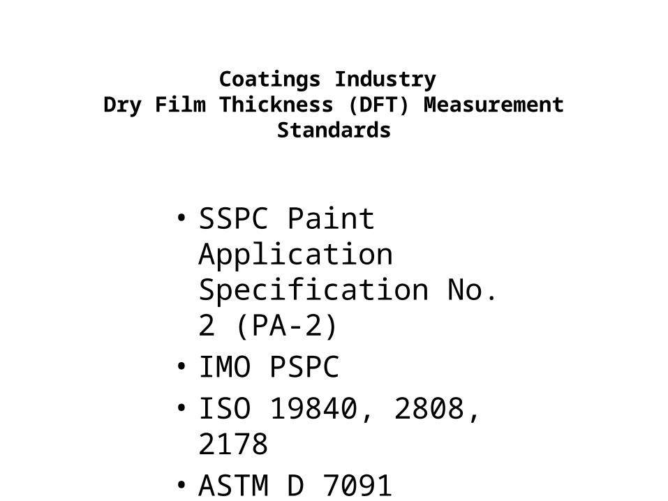
Coatings Industry Dry Film Thickness (DFT) Measurement Standards • SSPC Paint Application Specification No. 2 (PA-2) • IMO PSPC • ISO 19840, 2808, 2178 • ASTM D 7091
description
DFT Standards
Transcript of DFT Standards
Coatings Industry Dry Film Thickness (DFT) Measurement
Standards
• SSPC Paint Application Specification No. 2 (PA-2)
• IMO PSPC• ISO 19840, 2808, 2178• ASTM D 7091
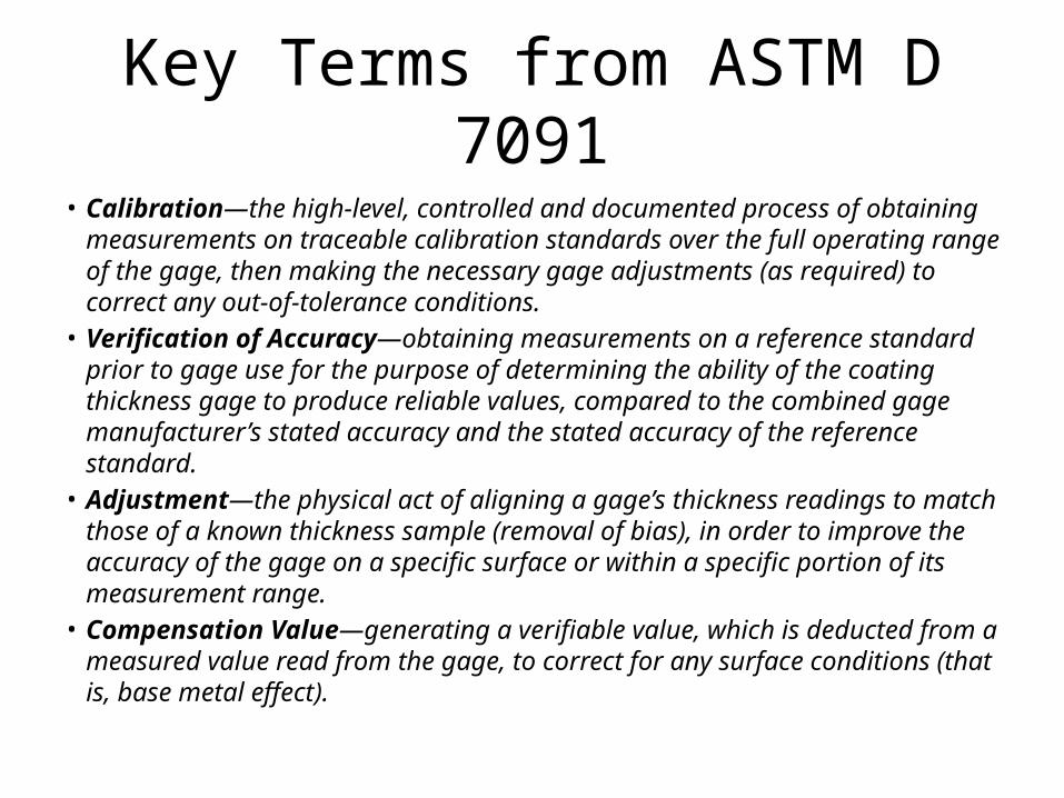
Key Terms from ASTM D 7091• Calibration—the high-level, controlled and documented process of obtaining
measurements on traceable calibration standards over the full operating range of the gage, then making the necessary gage adjustments (as required) to correct any out-of-tolerance conditions.
• Verification of Accuracy—obtaining measurements on a reference standard prior to gage use for the purpose of determining the ability of the coating thickness gage to produce reliable values, compared to the combined gage manufacturer’s stated accuracy and the stated accuracy of the reference standard.
• Adjustment—the physical act of aligning a gage’s thickness readings to match those of a known thickness sample (removal of bias), in order to improve the accuracy of the gage on a specific surface or within a specific portion of its measurement range.
• Compensation Value—generating a verifiable value, which is deducted from a measured value read from the gage, to correct for any surface conditions (that is, base metal effect).
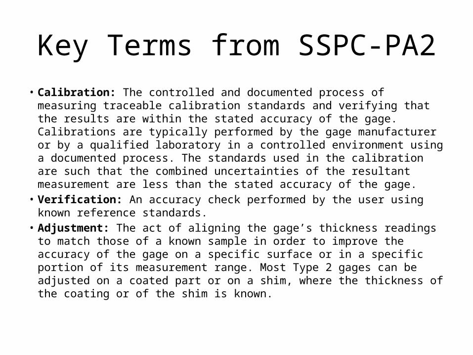
Key Terms from SSPC-PA2• Calibration: The controlled and documented process of measuring
traceable calibration standards and verifying that the results are within the stated accuracy of the gage. Calibrations are typically performed by the gage manufacturer or by a qualified laboratory in a controlled environment using a documented process. The standards used in the calibration are such that the combined uncertainties of the resultant measurement are less than the stated accuracy of the gage.
• Verification: An accuracy check performed by the user using known reference standards.
• Adjustment: The act of aligning the gage’s thickness readings to match those of a known sample in order to improve the accuracy of the gage on a specific surface or in a specific portion of its measurement range. Most Type 2 gages can be adjusted on a coated part or on a shim, where the thickness of the coating or of the shim is known.
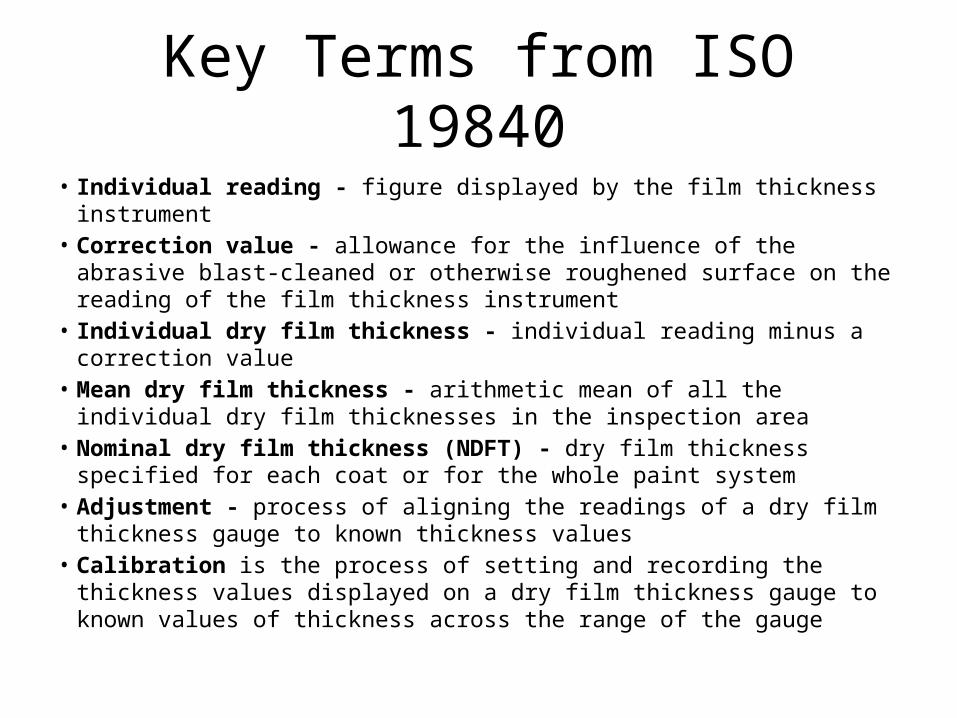
Key Terms from ISO 19840• Individual reading - figure displayed by the film thickness instrument• Correction value - allowance for the influence of the abrasive blast-cleaned
or otherwise roughened surface on the reading of the film thickness instrument
• Individual dry film thickness - individual reading minus a correction value• Mean dry film thickness - arithmetic mean of all the individual dry film
thicknesses in the inspection area• Nominal dry film thickness (NDFT) - dry film thickness specified for each
coat or for the whole paint system• Adjustment - process of aligning the readings of a dry film thickness gauge
to known thickness values• Calibration is the process of setting and recording the thickness values
displayed on a dry film thickness gauge to known values of thickness across the range of the gauge
SSPC PA-2 Verification & Adjustment
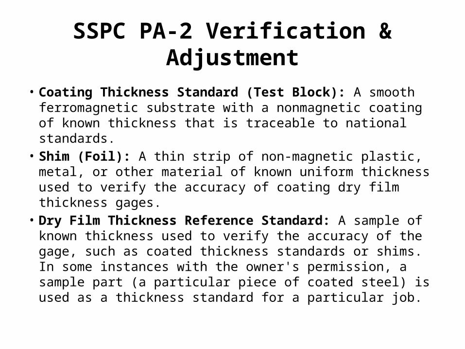
• Coating Thickness Standard (Test Block): A smooth ferromagnetic substrate with a nonmagnetic coating of known thickness that is traceable to national standards.
• Shim (Foil): A thin strip of non-magnetic plastic, metal, or other material of known uniform thickness used to verify the accuracy of coating dry film thickness gages.
• Dry Film Thickness Reference Standard: A sample of known thickness used to verify the accuracy of the gage, such as coated thickness standards or shims. In some instances with the owner's permission, a sample part (a particular piece of coated steel) is used as a thickness standard for a particular job.
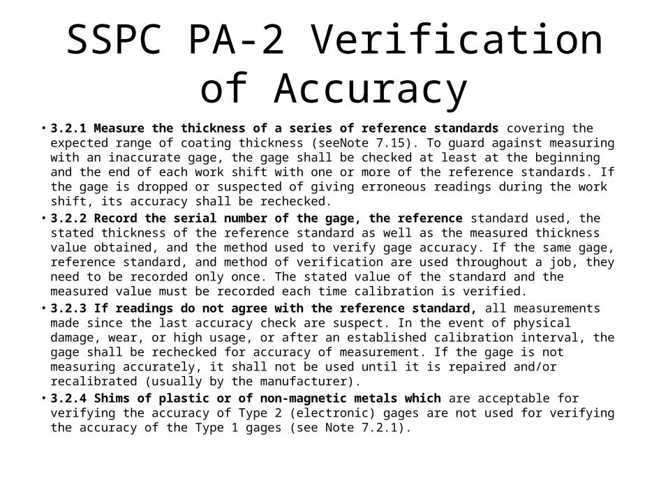
SSPC PA-2 Verification of Accuracy• 3.2.1 Measure the thickness of a series of reference standards covering the expected range of
coating thickness (seeNote 7.15). To guard against measuring with an inaccurate gage, the gage shall be checked at least at the beginning and the end of each work shift with one or more of the reference standards. If the gage is dropped or suspected of giving erroneous readings during the work shift, its accuracy shall be rechecked.
• 3.2.2 Record the serial number of the gage, the reference standard used, the stated thickness of the reference standard as well as the measured thickness value obtained, and the method used to verify gage accuracy. If the same gage, reference standard, and method of verification are used throughout a job, they need to be recorded only once. The stated value of the standard and the measured value must be recorded each time calibration is verified.
• 3.2.3 If readings do not agree with the reference standard, all measurements made since the last accuracy check are suspect. In the event of physical damage, wear, or high usage, or after an established calibration interval, the gage shall be rechecked for accuracy of measurement. If the gage is not measuring accurately, it shall not be used until it is repaired and/or recalibrated (usually by the manufacturer).
• 3.2.4 Shims of plastic or of non-magnetic metals which are acceptable for verifying the accuracy of Type 2 (electronic) gages are not used for verifying the accuracy of the Type 1 gages (see Note 7.2.1).
SSPC PA-2 Key Measurement Elements• NUMBER OF MEASUREMENTS:
– Make five (5) separate spot measurements (average of the gage readings, see Section 3.1.2) spaced arbitrarily over each 10 m2 (100 ft2) area to be measured.
– If the contracting parties agree, more than five (5) spot measurements may be taken in a given area.
• SPOT MEASUREMENT: Repeated gage readings, even at points close together, often differ due to small surface irregularities of the coating and the substrate. – Therefore, a minimum of three (3) gage readings shall be made for each spot
measurement of either the substrate or the coating. – For each new gage reading, move the probe to a new location within the 4 cm (1.5
inch) diameter circle defining the spot. – Discard any unusually high or low gage reading that is not repeated consistently.
Take the average of the acceptable gage readings as the spot measurement.
PA-2 Minimum Dry Film Thickness• The average of the spot measurements for each field joint lining
area shall not be less than the specified minimum thickness• No single spot measurement in any field joint lining shall be less
than 80% of the specified minimum thickness – Consider this statement in the context of how we have been calculating the BMR and Gauge adjustment. Does it require that we factor the BMR and Gauge Adjustments in to each Spot Measurement not just the final average?
• If the average of the spot measurements for the field joint lining meets or exceeds the specified minimum thickness, but one or more spot measurements is less than 80% of the specified minimum thickness, additional measurements will more precisely define the non-conforming area and facilitate repair
SSPC PA-2 Maximum Dry Film Thickness• The average of the spot measurements for each field joint
lining area shall not be more than the specified maximum thickness.
• No single spot measurement in any field joint lining area shall be more than 120% of the specified maximum thickness.
• If the average of the spot measurements for a given field joint lining area meets or falls below the specified maximum thickness, but one or more spot measurements is more than 120% of the specified maximum thickness, additional measurements will more precisely define the non-conforming area and facilitate repair
PA-2 Variation in Thickness Commentary• In any measurement there is a certain level of uncertainty. Two
inspectors using the same gage will not necessarily record the exact same number for a given spot measurement using the same 4 cm (1.5 inch) diameter circle.
• To allow for this natural fluctuation, an individual spot measurement is permitted to be below the specified minimum thickness as long as other spots in the 10 m2 (100 ft2) area are high enough to make the average thickness meet or exceed the specified minimum thickness.
• Similar reasoning applies to maximum thickness. • The 80% of specified minimum and 120% of specified maximum
allow for the accuracy of the gage and reference standards and for variations in the substrate.
IMO PSPC DFT Requirements
• NDFT is the nominal dry film thickness. A 90/10 practice means that 90% of all thickness measurements shall be greater than, or equal to, NDFT and none of the remaining 10% measurements shall be below 0.9 x NDFT.
• Maximum total dry film thickness according to manufacturer’s detailed specifications.
• Care shall be taken to avoid increasing the thickness in an exaggerated way. Wet film thickness shall be regularly checked during application.
• Type of gauge and calibration in accordance with SSPC-PA2:2004. Paint Application Specification No.2.
IMO PSPC DFT Requirements
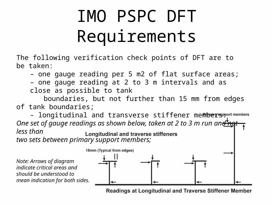
The following verification check points of DFT are to be taken:– one gauge reading per 5 m2 of flat surface areas;– one gauge reading at 2 to 3 m intervals and as close as possible to tank
boundaries, but not further than 15 mm from edges of tank boundaries;
– longitudinal and transverse stiffener members:One set of gauge readings as shown below, taken at 2 to 3 m run and not less thantwo sets between primary support members;
Note: Arrows of diagram indicate critical areas and should be understood tomean indication for both sides.
IMO PSPC DFT Requirements• 3 gauge readings for each set of primary support members and 2
gauge readings for each set of other members as indicated by the arrows in the diagram;
• For primary support members (girders and transverses) one set of gauge readings for 2 to 3 m run as shown in figure 3 above but not less than three sets;
• Around openings one gauge reading from each side of the opening;• Five gauge readings per square metre (m2) but not less than three
gauge readings taken at complex areas (i.e., large brackets of primary support members); and
• Additional spot checks are to be taken to verify coating thickness for any area considered necessary by the coating inspector.
ISO 19840Paints and varnishes — Corrosion
protection of steel structuresby protective paint systems —
Measurement of, and acceptancecriteria for, the thickness of dry films on
rough surfaces
ISO 19840• For the purposes of this standard, any specified thickness is taken to be
nominal…and the dry film thickness is the typical thickness above the peaks of the surface profile.
• The procedure described in this International Standard is based on the use of instruments of the permanent magnet and inductive magnet type. Instruments are adjusted to zero and a known thickness on a smooth surface.
• Measurements taken on a coating on a roughened steel substrate will therefore be higher than the actual value above the peaks of the profile. The thickness of the dry film above the peaks of the profile is defined as the instrument reading minus an appropriate correction value.
• The dry film thickness is obtained by using the appropriate correction value applied to readings based on adjustment on a smooth, flat, steel surface.
ISO 19840• Where individual readings, based on adjustment on a smooth, flat
steel surface without the use of correction values, are specified or agreed, it is important to recognize that this method does not conform with this International Standard.
• This standard is applicable if the nominal dry film thickness is 40 μm or greater.
ISO 19840 Terms & Definitions• Dry film thickness (DFT) - thickness of a coating remaining over the peaks of a rough
surface when the coating has hardened• Individual reading - figure displayed by the film thickness instrument• Correction value - allowance for the influence of the abrasive blast-cleaned or
otherwise roughened surface on the reading of the film thickness instrument• Individual dry film thickness - individual reading minus a correction value• Mean dry film thickness - arithmetic mean of all the individual dry film thicknesses
in the inspection area• Nominal dry film thickness (NDFT) - dry film thickness specified for each coat or for
the whole paint system• Inspection area - designated area for which a sampling plan is established and which
can be the whole structure or sections of the whole structure• Sampling plan - plan which defines the number of measurements to be taken on an
inspection area• Adjustment - process of aligning the readings of a dry film thickness gauge to known
thickness values
ISO 19840
• All instruments for measuring dry film thicknesses will give variable values within very small areas on roughened surfaces due to the influence of the surface roughness and the variations inherent in the method(s) used to apply the paint.
• The type of measuring equipment and material shall be specified or agreed between the interested parties before the measurements commence.
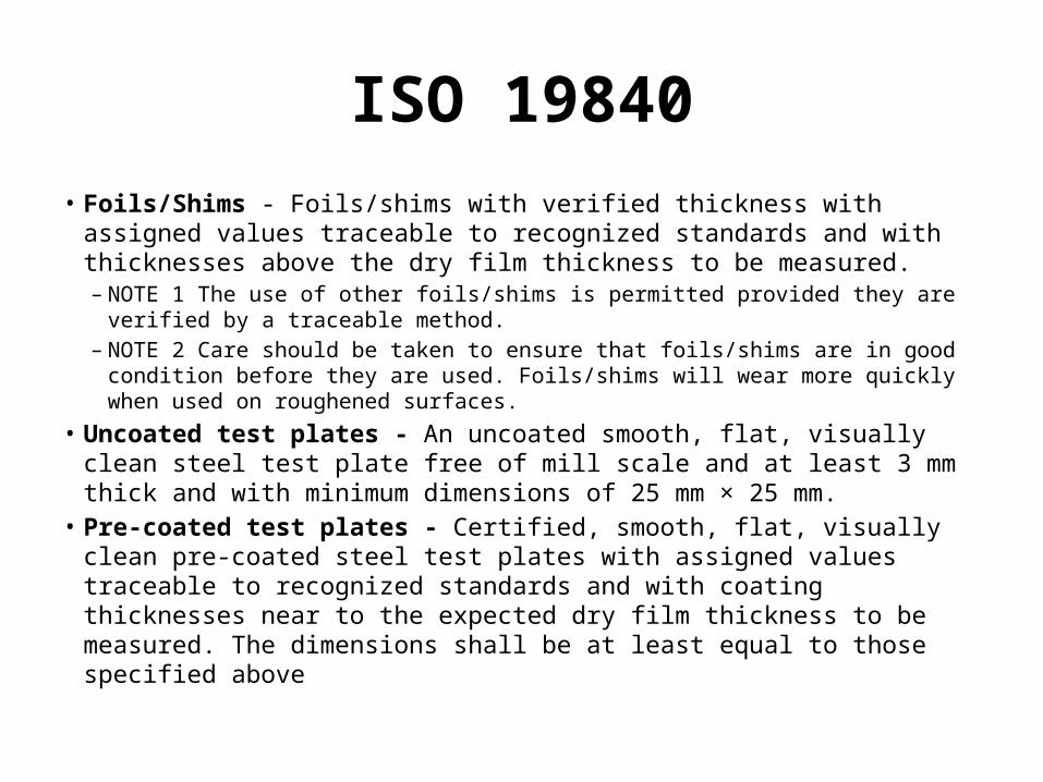
ISO 19840• Foils/Shims - Foils/shims with verified thickness with assigned values
traceable to recognized standards and with thicknesses above the dry film thickness to be measured.– NOTE 1 The use of other foils/shims is permitted provided they are verified by a
traceable method.– NOTE 2 Care should be taken to ensure that foils/shims are in good condition
before they are used. Foils/shims will wear more quickly when used on roughened surfaces.
• Uncoated test plates - An uncoated smooth, flat, visually clean steel test plate free of mill scale and at least 3 mm thick and with minimum dimensions of 25 mm × 25 mm.
• Pre-coated test plates - Certified, smooth, flat, visually clean pre-coated steel test plates with assigned values traceable to recognized standards and with coating thicknesses near to the expected dry film thickness to be measured. The dimensions shall be at least equal to those specified above
ISO 19840 Sampling Plan
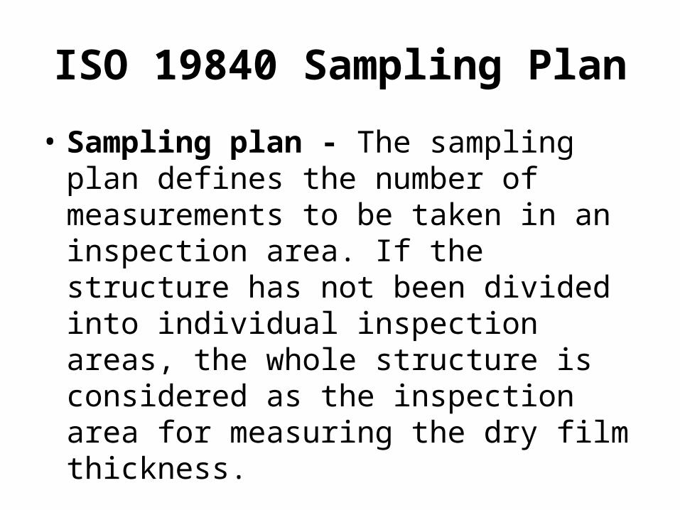
• Sampling plan - The sampling plan defines the number of measurements to be taken in an inspection area. If the structure has not been divided into individual inspection areas, the whole structure is considered as the inspection area for measuring the dry film thickness.
ISO 19840 Sampling Plan
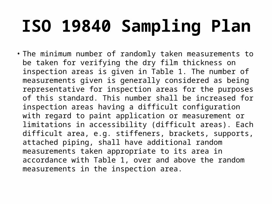
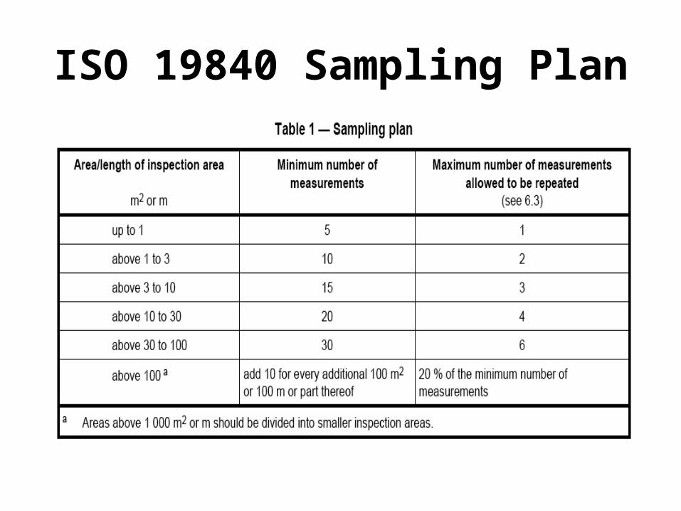
• The minimum number of randomly taken measurements to be taken for verifying the dry film thickness on inspection areas is given in Table 1. The number of measurements given is generally considered as being representative for inspection areas for the purposes of this standard. This number shall be increased for inspection areas having a difficult configuration with regard to paint application or measurement or limitations in accessibility (difficult areas). Each difficult area, e.g. stiffeners, brackets, supports, attached piping, shall have additional random measurements taken appropriate to its area in accordance with Table 1, over and above the random measurements in the inspection area.
ISO 19840 Sampling Plan
ISO 19840
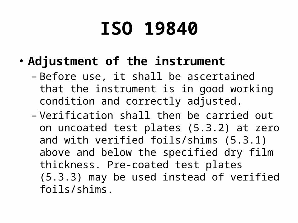
• Adjustment of the instrument– Before use, it shall be ascertained that the
instrument is in good working condition and correctly adjusted.
– Verification shall then be carried out on uncoated test plates (5.3.2) at zero and with verified foils/shims (5.3.1) above and below the specified dry film thickness. Pre-coated test plates (5.3.3) may be used instead of verified foils/shims.
ISO 19840
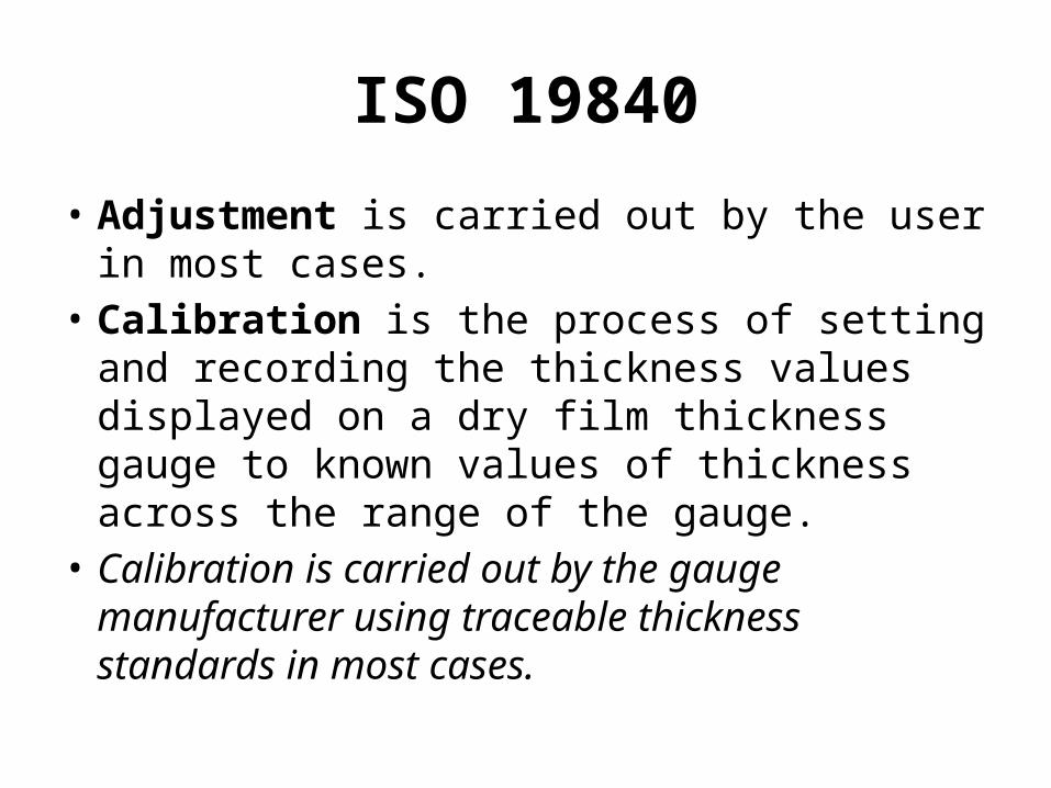
• Adjustment is carried out by the user in most cases.
• Calibration is the process of setting and recording the thickness values displayed on a dry film thickness gauge to known values of thickness across the range of the gauge.
• Calibration is carried out by the gauge manufacturer using traceable thickness standards in most cases.
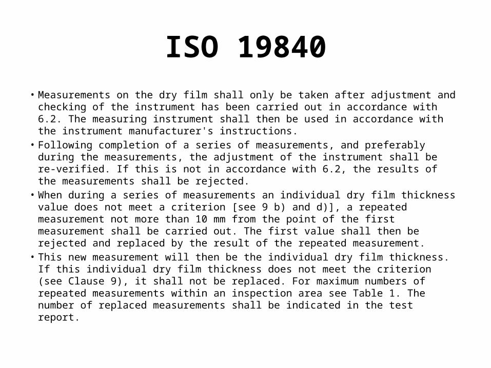
ISO 19840• Measurements on the dry film shall only be taken after adjustment and checking
of the instrument has been carried out in accordance with 6.2. The measuring instrument shall then be used in accordance with the instrument manufacturer's instructions.
• Following completion of a series of measurements, and preferably during the measurements, the adjustment of the instrument shall be re-verified. If this is not in accordance with 6.2, the results of the measurements shall be rejected.
• When during a series of measurements an individual dry film thickness value does not meet a criterion [see 9 b) and d)], a repeated measurement not more than 10 mm from the point of the first measurement shall be carried out. The first value shall then be rejected and replaced by the result of the repeated measurement.
• This new measurement will then be the individual dry film thickness. If this individual dry film thickness does not meet the criterion (see Clause 9), it shall not be replaced. For maximum numbers of repeated measurements within an inspection area see Table 1. The number of replaced measurements shall be indicated in the test report.
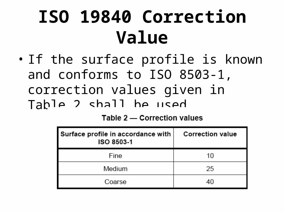
ISO 19840 Correction Value
• If the surface profile is known and conforms to ISO 8503-1, correction values given in Table 2 shall be used.
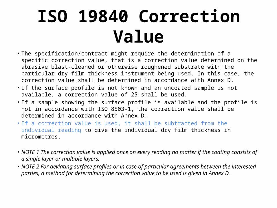
ISO 19840 Correction Value• The specification/contract might require the determination of a specific correction
value, that is a correction value determined on the abrasive blast-cleaned or otherwise roughened substrate with the particular dry film thickness instrument being used. In this case, the correction value shall be determined in accordance with Annex D.
• If the surface profile is not known and an uncoated sample is not available, a correction value of 25 shall be used.
• If a sample showing the surface profile is available and the profile is not in accordance with ISO 8503-1, the correction value shall be determined in accordance with Annex D.
• If a correction value is used, it shall be subtracted from the individual reading to give the individual dry film thickness in micrometres.
• NOTE 1 The correction value is applied once on every reading no matter if the coating consists of a single layer or multiple layers.
• NOTE 2 For deviating surface profiles or in case of particular agreements between the interested parties, a method for determining the correction value to be used is given in Annex D.
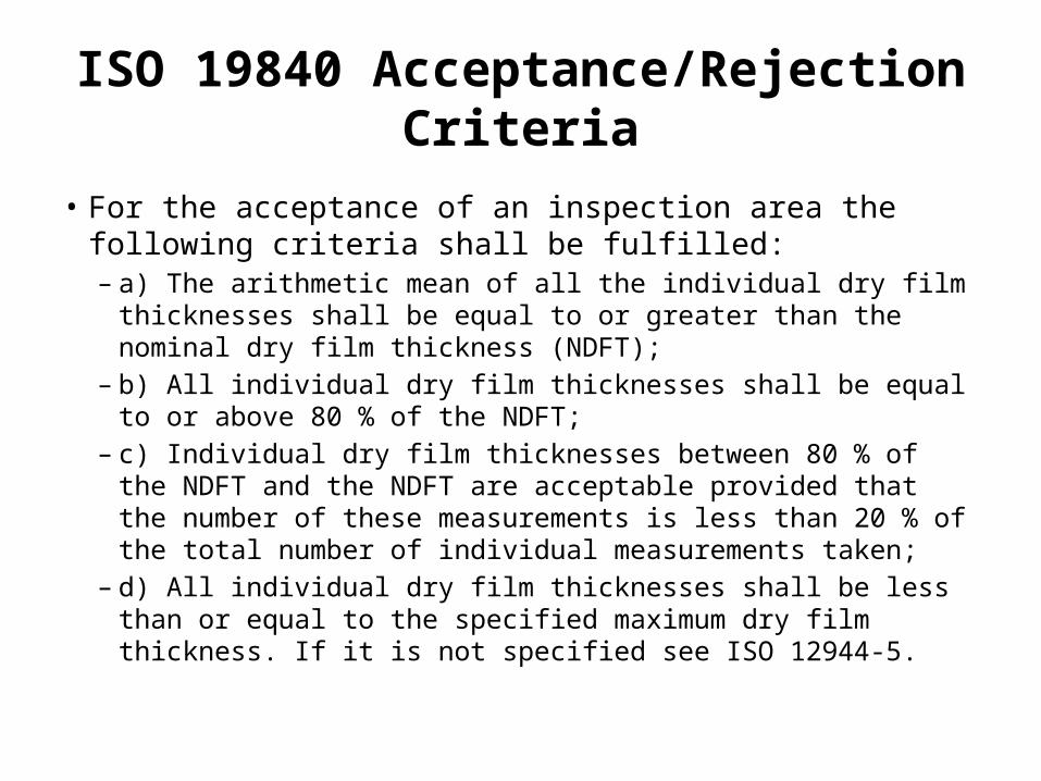
ISO 19840 Acceptance/Rejection Criteria
• For the acceptance of an inspection area the following criteria shall be fulfilled:– a) The arithmetic mean of all the individual dry film thicknesses shall
be equal to or greater than the nominal dry film thickness (NDFT);– b) All individual dry film thicknesses shall be equal to or above 80 %
of the NDFT;– c) Individual dry film thicknesses between 80 % of the NDFT and the
NDFT are acceptable provided that the number of these measurements is less than 20 % of the total number of individual measurements taken;
– d) All individual dry film thicknesses shall be less than or equal to the specified maximum dry film thickness. If it is not specified see ISO 12944-5.
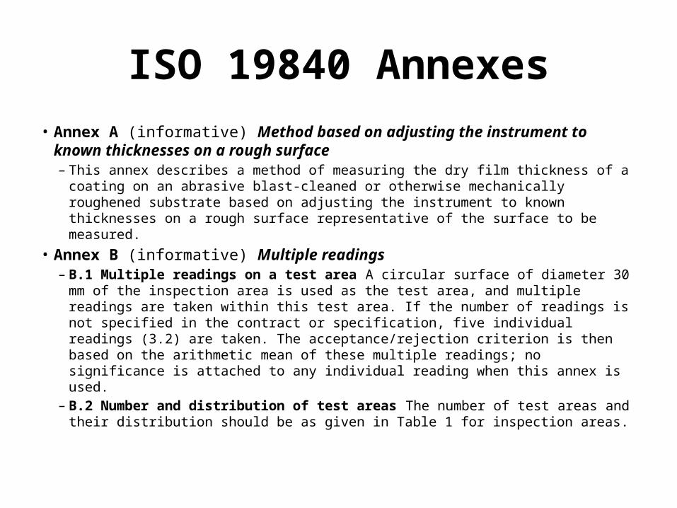
ISO 19840 Annexes• Annex A (informative) Method based on adjusting the instrument to
known thicknesses on a rough surface– This annex describes a method of measuring the dry film thickness of a coating
on an abrasive blast-cleaned or otherwise mechanically roughened substrate based on adjusting the instrument to known thicknesses on a rough surface representative of the surface to be measured.
• Annex B (informative) Multiple readings– B.1 Multiple readings on a test area A circular surface of diameter 30 mm of
the inspection area is used as the test area, and multiple readings are taken within this test area. If the number of readings is not specified in the contract or specification, five individual readings (3.2) are taken. The acceptance/rejection criterion is then based on the arithmetic mean of these multiple readings; no significance is attached to any individual reading when this annex is used.
– B.2 Number and distribution of test areas The number of test areas and their distribution should be as given in Table 1 for inspection areas.
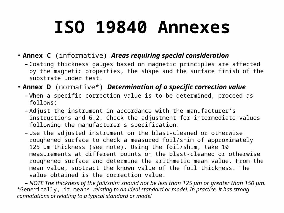
ISO 19840 Annexes• Annex C (informative) Areas requiring special consideration
– Coating thickness gauges based on magnetic principles are affected by the magnetic properties, the shape and the surface finish of the substrate under test.
• Annex D (normative*) Determination of a specific correction value– When a specific correction value is to be determined, proceed as follows:– Adjust the instrument in accordance with the manufacturer's instructions and 6.2.
Check the adjustment for intermediate values following the manufacturer's specification.
– Use the adjusted instrument on the blast-cleaned or otherwise roughened surface to check a measured foil/shim of approximately 125 μm thickness (see note). Using the foil/shim, take 10 measurements at different points on the blast-cleaned or otherwise roughened surface and determine the arithmetic mean value. From the mean value, subtract the known value of the foil thickness. The value obtained is the correction value.
– NOTE The thickness of the foil/shim should not be less than 125 μm or greater than 150 μm.*Generically, it means relating to an ideal standard or model. In practice, it has strong connotations of relating
to a typical standard or model
ISO 19840 Annexes
• Annex E (informative) Example of a test report form
• A
ASTM D 7091-05
• 5.5 Most electronic coating thickness-measuring gages can be verified for accuracy using either traceable reference stan- dards or measured non-metallic shims. Gage operation should be verified on prepared, uncoated substrate having the same composition, shape and surface roughness to which the coating will be applied to, for the intended range of use. If necessary, the gage should be adjusted as described in 7.6 or 7.7. Gages that cannot be adjusted by the user should be returned to the manufacturer for calibration if the readings obtained on the reference standards or shims are outside of the combined accuracy of the standard/shim and the manufacturer’s stated gage accuracy.
ASTM D 7091-05 Considerations
• 5.6 Type 2 gages should not be used on soft or tacky coatings, as the pressure on the probe can indent the coating yielding false low measurements, or coating materials may contaminate the probe yielding false high measurements. A shim (of known thickness) can be placed on top of the soft/tacky coating film and a measurement of the coating thickness obtained by subtracting the shim thickness from the total measurement of the shim and the coating. Note that some Type 2 gages can be programmed to automatically deduct the shim thickness (known as “zero offset”).
ASTM D 7091-05 Considerations
• Type 2 gages may be sensitive (to some degree) to substrate effects including, but not limited to edges, corners and holes in the substrate, as well as substrate thickness, curvature or conductivity, or both. In general, the user should remain a minimum of 25 mm (1 in.) from edges when measuring coating thickness, unless the probe specification indicates otherwise.
• The manufacturer’s specifications will contain a temperature operating range. Use of the gage or the probe outside of this range may generate false coating thickness measurements and may damage the instrument.
ASTM D 7091-05 Considerations• 7.1 Calibration of coating thickness gages is performed by the
equipment manufacturer, an authorized agent, or by an authorized, trained calibration laboratory in a controlled environment using a documented process.
• 7.2 Type 1 (magnetic pull-off) and Type 2 (electronic) coating thickness gages should be verified for accuracy (and adjusted if required and when possible) prior to, during and after each period of use. Type 1 and Type 2 gages can be verified for accuracy using coated/plated reference standards or shims (see Note 5 and Appendix X1). The gage should be verified for accuracy in the intended range of use. Also, the probe should be examined for cleanliness before verifying the accuracy and before obtaining coating thickness measure- ments.
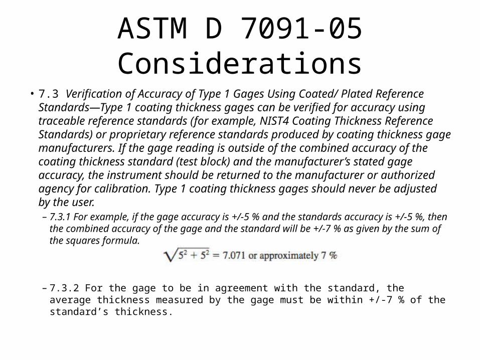
ASTM D 7091-05 Considerations• 7.3 Verification of Accuracy of Type 1 Gages Using Coated/ Plated Reference
Standards—Type 1 coating thickness gages can be verified for accuracy using traceable reference standards (for example, NIST4 Coating Thickness Reference Standards) or proprietary reference standards produced by coating thickness gage manufacturers. If the gage reading is outside of the combined accuracy of the coating thickness standard (test block) and the manufacturer’s stated gage accuracy, the instrument should be returned to the manufacturer or authorized agency for calibration. Type 1 coating thickness gages should never be adjusted by the user.– 7.3.1 For example, if the gage accuracy is +/-5 % and the standards accuracy is +/-5 %,
then the combined accuracy of the gage and the standard will be +/-7 % as given by the sum of the squares formula.
– 7.3.2 For the gage to be in agreement with the standard, the average thickness measured by the gage must be within +/-7 % of the standard’s thickness.
ASTM D 7091-05 Considerations
• 7.4 Verification of Accuracy of Type 1 Gages Using Shims— Type 1 coating thickness gages may be verified for accuracy using shims (see Note 5 and Appendix X1).
• 7.6 Verification of Accuracy of Type 2 Gages Using Coated/ Plated Reference Standards—Type 2 coating thickness gages can be verified for accuracy using traceable reference standards (for example, NIST Coating Thickness Reference Standards)
• 7.7 Verification of Accuracy of Type 2 Gages Using Shims— Type 2 coating thickness gages can be verified for accuracy using shims. The shim(s) representing the intended range of use should be placed onto the prepared, uncoated surface, and a measurement taken.
ASTM D 7091-05 Frequency of Measurement
• The thickness of a coating or a coating system can vary from area to area on a structure or part. Accordingly, it is recommended that a number of measurements be obtained and the arithmetic mean calculated to determine the high, low and average coating thickness in a given area.
• 8.2 For larger structures, five spot measurements (each spot measurement being the average of three individual gage measurements acquired within a 12 mm (1⁄2 in.) diameter circle) should be obtained in every 9 m2(100 ft2) area of coated surface. The number of areas to measure is dependent on the size of the structure or part.
ASTM D 7091-05 Frequency of Measurement
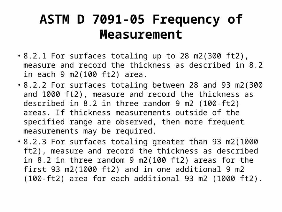
• 8.2.1 For surfaces totaling up to 28 m2(300 ft2), measure and record the thickness as described in 8.2 in each 9 m2(100 ft2) area.
• 8.2.2 For surfaces totaling between 28 and 93 m2(300 and 1000 ft2), measure and record the thickness as described in 8.2 in three random 9 m2 (100-ft2) areas. If thickness measurements outside of the specified range are observed, then more frequent measurements may be required.
• 8.2.3 For surfaces totaling greater than 93 m2(1000 ft2), measure and record the thickness as described in 8.2 in three random 9 m2(100 ft2) areas for the first 93 m2(1000 ft2) and in one additional 9 m2 (100-ft2) area for each additional 93 m2 (1000 ft2).
ASTM D 7091-05 Appendix X1
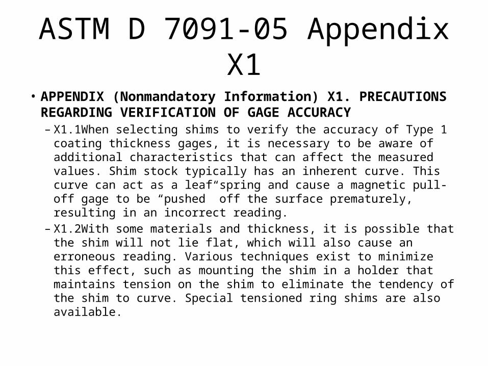
• APPENDIX (Nonmandatory Information) X1. PRECAUTIONS REGARDING VERIFICATION OF GAGE ACCURACY– X1.1When selecting shims to verify the accuracy of Type 1 coating
thickness gages, it is necessary to be aware of additional characteristics that can affect the measured values. Shim stock typically has an inherent curve. This curve can act as a leaf spring and cause a magnetic pull-off gage to be “pushed” off the surface prematurely, resulting in an incorrect reading.
– X1.2With some materials and thickness, it is possible that the shim will not lie flat, which will also cause an erroneous reading. Various techniques exist to minimize this effect, such as mounting the shim in a holder that maintains tension on the shim to eliminate the tendency of the shim to curve. Special tensioned ring shims are also available.
ASTM D 7091-05 Appendix X1
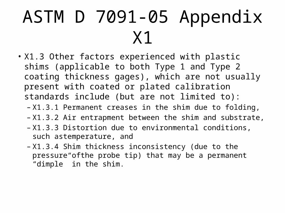
• X1.3 Other factors experienced with plastic shims (applicable to both Type 1 and Type 2 coating thickness gages), which are not usually present with coated or plated calibration standards include (but are not limited to):– X1.3.1 Permanent creases in the shim due to folding,– X1.3.2 Air entrapment between the shim and substrate, – X1.3.3 Distortion due to environmental conditions, such
astemperature, and – X1.3.4 Shim thickness inconsistency (due to the pressure ofthe
probe tip) that may be a permanent “dimple” in the shim.
ASTM D 7091-05 Appendix X1
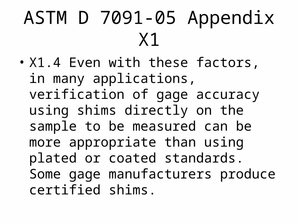
• X1.4 Even with these factors, in many applications, verification of gage accuracy using shims directly on the sample to be measured can be more appropriate than using plated or coated standards. Some gage manufacturers produce certified shims.