DFT Installation & Maintenance Manual
24
“Check Valve Doctor ™ ” Installation & Maintenance Manual ISO 9001:2000 For additional information call 800-206-4013 610-363-8903 Fax: 610-524-9242 email: [email protected] www.dft-valves.com P.O. Box 566 Exton, PA 19341-0566
Transcript of DFT Installation & Maintenance Manual
“Check Valve Doctor™”
Installation & Maintenance Manual
ISO 9001:2000
For additional information call
800-206-4013
610-363-8903 Fax: 610-524-9242
email: [email protected]
www.dft-valves.com
P.O. Box 566 Exton, PA 19341-0566
www.dft-valves.com 2 610-363-8903
DFT® DFT specializes in spring assisted In-Line Check Valves that prevent Water Hammer and reverse flow and insure long life if properly sized for the flow not the line size. DFT customizes the internal components for optimal performance without changing the line size. DFT In-Line check valves do not rely on gravity or reverse fluid flow to close. Instead as the forward velocity of the fluid slows, the spring assist starts to close the disc. Due to the spring assist and short travel distance of the disc, by the time forward velocity has decreased to zero, the valve disc has reached the seat and the valve is closed. With reverse flow eliminated, the forces necessary to produce water hammer on both the upstream and downstream sides of the valve are substantially eliminated. DFT’s objective is to solve and prevent check valve problems and failures in critical service applications. All valves are built and tested at our facility in Exton, PA and subject to our ISO 9001 Quality Process.
DFT is considered the control valve of check valves, the “Check Valve Doctor™”. Our check valve sizing program insures you will know in advance what to expect from the check valve as opposed to after start up. DFT In-Line check valves are used in all industries. They include chemical, food & beverage, mining, oil & gas, power, pulp & paper, refining and steel. DFT In-Line check valves should provide trouble free service. Occasionally problems do arise or inspection is required. This manual provides information for inspection and repairs of your DFT check valves should the need arise. No special tools are needed. Check Valve Assistance Contact DFT at 800-206-4013 for assistance, questions or the Authorized DFT repair facility in your area. DFT is available to review your check valve sizing requirements and assist in selecting the proper check valve.
Table of Contents
ITEM PAGE ITEM PAGE ALC™…………………….. 6 - 7 PDC®…………………….…. 16 - 17 Basic-Check®……………. 8 -9 Repair Kits/Spare Parts….. 4 DLC®……………………… 10 Restrictor Check………….. 8 - 9 DSV™……………………. 11 SCV®……………………….. 18 - 19 Excalibur®………………... 12 - 13 SCV-R™…………………… 20 - 21 Full Face Seat Illustration Back Cover Split Face Seat Illustration.. Back Cover GLC®……………………… 14 - 15 Trouble Shooting Guide….. 3 Installation Procedures…. 3 Vacuum Breaker………….. 8 - 9 Materials of Construction. 5 WLC®…………………….… 22 - 23 Basic-Check, Excalibur, DLC, GLC, PDC, SCV, WLC are registered trademarks of DFT® Inc.

www.dft-valves.com 3 610-363-8903
INSTALLATION PROCEDURES All DFT® In-Line check valves can be installed in the line in any orientation. The operation of the DFT check valve is not affected by the position of the valve itself. The only requirement is that the flow arrow on the body casting must be pointed in the direction of the flow. If the DFT check valve is to be installed in an orientation with flow downward, that should be specified when ordering. A stronger spring may be required to compensate for the weight of the disc and any static head. Static head should be considered for any check valve. The operation of DFT In-Line check valves is not affected by its proximity to elbows, tees, control valves etc. However, installing DFT In-Line check valves directly to the outlet of such devices may result in decreased life due to the turbulence caused by the fitting. DFT recommends that all DFT In-Line check valves be installed a minimum of five pipe diameters downstream of any fitting that could cause turbulence. Flange gaskets: The ALC™, DLC®, Excalibur® and new “Full Face” GLC® and PDC® can use both non-metallic and spiral wound gaskets for “all” ASME Classes. Non-metallic gaskets are recommended for ASME Class 150 and 300 WLC®’s and older “Split Face” GLC’s and PDC’s. Spiral wound gaskets can be used for all ASME Class 600 and higher valves. An illustration of end flange gaskets is shown on the back cover. (API 601 is a standard for ASME B16.5 end flange gaskets.)
Check Valve Trouble Shooting Guide
Symptom Cause Solutions Water hammer, loud noise, vibration, ruptured piping, equipment damage
Slow closing check valve In-Line spring assisted check valve.
Stem wear (pointed stem), elongated seat guide, bushing wear
Low flow, pulsating flow, improper sizing
Custom sizing of the check valve internals. PDC for reciprocating air or gas mediums.
Excessive seat leakage (Greater than MSS-SP61)
Dirt, trash, foreign substance in the valve
Clean out the valve. Install strainers if it is a reoccurring problem. Install a soft seat if bubble tight shutoff is required.
Noise, clicking, tapping Low flow, pulsating flow, improper sizing
Custom sizing of the check valve internals. PDC for reciprocating air or gas mediums.
Reverse flow Slow closing check valve In-Line spring assisted check valve.
Component breakage, valve failure Reciprocating compressor PDC for reciprocating air or gas mediums.
Missing internals Valve not full open, pulsing flow, improper sizing
Custom sizing of the check valve internals. PDC for reciprocating air or gas mediums.
www.dft-valves.com 4 610-363-8903
REPAIR KITS/SPARE PARTS
Repair Kits are available for all but the DLC® and Cast Iron check valves. If you have any questions regarding the repair kit for your DFT® check valve, contact DFT at 800-206-4013, 610-363-8903 or [email protected] Additional comments:
1. Serial Numbers – ALC™, Excalibur®, GLC®, PDC® and certain WLC®’s.
Providing the valve Serial Number will insure receipt of the proper repair kit for your valve. • All Excalibur’s, GLC’s and PDC’s contain Serial Numbers. They are located
on the valve nameplate.
• “Special” WLC valves are also provided with Serial Numbers on the valve nameplate.
• Basic-Check® style valves, Cast Iron GLC’s and WLC’s, DLC’s and SCV®’s
do not contain serial numbers. 2. Soft seats are available with “Repair Kits”. Contact DFT.
WARNING: If the system fluid is hazardous, take appropriate precautions before performing maintenance or repair. Make sure to bleed off pressure from the line before removing the valve. Once removed from the line, flush and cycle the valve to remove any remnants of the media that could occupy cavities or pockets within the valve such as between the body and seat or bushing and body.

www.dft-valves.com 5 610-363-8903
STANDARD MATERIALS OF CONSTRUCTION
COMPONENT DFT® PRODUCT CARBON STEEL BODY
STAINLESS STEEL BODY
Body (1)
ALC™, Excalibur®, GLC®, PDC®, WLC®
A216 WCB A351 CF8M
DLC®, SCV®, SCV-R™ N/A A351 CF8M
Disc/stem assembly
ALC 316 SS/ Nitronic 60 316 SS/ Nitronic 60 BSS®, DLC, SCV, SCV-R N/A A240 316 SS disc
Excalibur, GLC, WLC A351 CF8M/A479 316 A351 CF8M/A479 316 PDC A351 CF8M disc A351 CF8M disc
WLC 1” & 1-1/2” Class 900+ 17-7 disc 17-7 disc
Disc guide PDC A479 316 SS A479 316 SS
Seat
ALC 316 SS 316 SS BSS N/A A582 303 SS
DLC, SCV, SCV-R N/A A351 CF8M Excalibur, GLC, PDC, WLC A351 CF8M A351 CF8M
Spring
Excalibur, GLC, PDC, WLC A313 316 A313 316 ALC Inconel® X-750 Inconel X-750
DLC, SCV, SCV-R N/A Inconel X-750
Ball check spring
PDC Inconel X-750 Inconel X-750
Bushing ALC, Excalibur, GLC, WLC A479 316 SS A479 316 SS
PDC Rulon® Rulon
Bolting Excalibur A193-B7 (Stud) & A194-2H (Nut)
Gaskets ALC, Excalibur, GLC CFG (2) CFG (2)
Excalibur ASME Class 600+ 316 Spiral wound with Flexible Graphite Filler
Body Seal SCV, SCV-R N/A Zelon
PDC Buna-N Buna-N
Ball check PDC Teflon® Teflon
Guide ring PDC Teflon Teflon
Orifice plug PDC A479 316 SS A479 316 SS
Seal ring PDC Teflon/Hastelloy® C276 Teflon/Hastelloy C276
Spring retainer – ball check
PDC A479 316 SS A479 316 SS
Guard BSS ¼”, 3/8” & ½” N/A 303SS
BSS ¾” to 2-1/2” N/A A351 CF8M
Retaining ring BSS N/A A313 316SS
Seat retainer assembly
SCV-R N/A 316SS
Notes: 1. Other Body materials available – Alloy 20, Hastelloy C, Monel®, Titanium, etc. 2. 316/Graphite material.
www.dft-valves.com 6 610-363-8903
ALC™ MAINTENANCE PROCEDURES
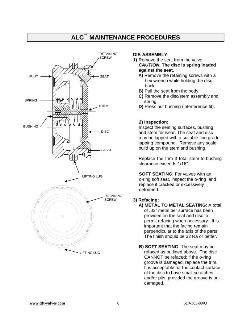
DIS-ASSEMBLY: 1) Remove the seat from the valve.
CAUTION: The disc is spring loaded against the seat. A) Remove the retaining screws with a
hex wrench while holding the disc back.
B) Pull the seat from the body. C) Remove the disc/stem assembly and
spring. D) Press out bushing (interference fit). 2) Inspection: Inspect the seating surfaces, bushing and stem for wear. The seat and disc may be lapped with a suitable fine grade lapping compound. Remove any scale build up on the stem and bushing. Replace the trim if total stem-to-bushing clearance exceeds 1/16”. SOFT SEATING: For valves with an o-ring soft seat, inspect the o-ring and replace if cracked or excessively deformed.
3) Refacing: A) METAL TO METAL SEATING: A total
of .03” metal per surface has been provided on the seat and disc to permit refacing when necessary. It is important that the facing remain perpendicular to the axis of the parts. The finish should be 32 Ra or better.
B) SOFT SEATING: The seat may be
refaced as outlined above. The disc CANNOT be refaced; if the o-ring groove is damaged, replace the trim. It is acceptable for the contact surface of the disc to have small scratches and/or pits, provided the groove is un-damaged.
BODY SEAT
DISC BUSHING
SPRING
GASKET
STEM
LIFTING LUG
LIFTING LUG
RETAINING SCREW
RETAINING SCREW
www.dft-valves.com 7 610-363-8903
ALC™ MAINTENANCE PROCEDURES 4) Soft Seat Replacement:
A) To replace the ring, pry it out of the groove using a thin piece of metal (a .005" thick feeler gage works well) taking care not to scratch the inside wall of the o-ring groove.
B) Clean out the groove. Lubricate a new o-ring with water soluble lubricant such as dishwashing detergent or suitable lubricant compatible with the process fluid.
C) To install the new o-ring, push one section of the o-ring into the groove with your thumb or a soft roller, then push the section 1800 opposite from the first into the groove. Continue by pushing in the o-ring at points 900 to the original sections. Finally, push the rest of the ring into the groove.
D) Rub the o-ring in a circular motion in the groove with your thumb to even-out any bumps.
RE-ASSEMBLY: 1) Seat Installation
A) Press bushing into body. B) Place spring into the body. C) Insert the disc/stem assembly D) Install the body gasket. E) Lower the seat into the body and
install the retaining screws with a hex wrench.
2) Stroke the disc to work the valve a couple of times to check for free disc movement.
3) Re-install the valve in the line with the flow arrow on the body pointing in the direction of flow.
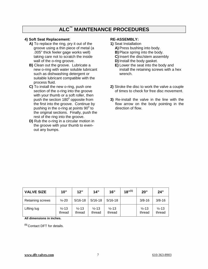
VALVE SIZE 10” 12” 14” 16” 18”(1) 20” 24”
Retaining screws ¼-20 5/16-18 5/16-18 5/16-18 3/8-16 3/8-16
Lifting lug ½-13 thread
½-13 thread
½-13 thread
½-13 thread
½-13 thread
½-13 thread
All dimensions in inches. (1) Contact DFT for details.
www.dft-valves.com 8 610-363-8903
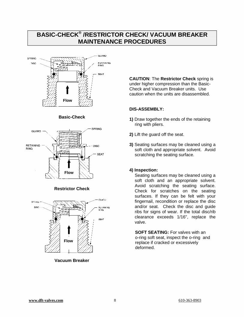
BASIC-CHECK® /RESTRICTOR CHECK/ VACUUM BREAKER MAINTENANCE PROCEDURES
Basic-Check
Restrictor Check
Vacuum Breaker
CAUTION: The Restrictor Check spring is under higher compression than the Basic-Check and Vacuum Breaker units. Use caution when the units are disassembled. DIS-ASSEMBLY: 1) Draw together the ends of the retaining
ring with pliers. 2) Lift the guard off the seat. 3) Seating surfaces may be cleaned using a
soft cloth and appropriate solvent. Avoid scratching the seating surface.
4) Inspection:
Seating surfaces may be cleaned using a soft cloth and an appropriate solvent. Avoid scratching the seating surface. Check for scratches on the seating surfaces. If they can be felt with your fingernail, recondition or replace the disc and/or seat. Check the disc and guide ribs for signs of wear. If the total disc/rib clearance exceeds 1/16", replace the valve. SOFT SEATING: For valves with an o-ring soft seat, inspect the o-ring and replace if cracked or excessively deformed.
Flow
Flow
Flow

www.dft-valves.com 9 610-363-8903
BASIC-CHECK® /RESTRICTOR CHECK/ VACUUM BREAKER MAINTENANCE PROCEDURES
5) Soft Seat Replacement:
A) To replace the ring, pry it out of the groove using a thin piece of metal (a .005" thick feeler gage works well) taking care not to scratch the bottom of the o-ring groove.
B) Clean out the groove.
C) Lubricate a new o-ring with water
soluble lubricant such as dishwashing detergent.
D) To install the new o-ring, push one
section of the o-ring into the groove with thumb or a soft roller, then push the section 1800 opposite from the first into the groove. Continue by pushing in the o-ring at points 900 to the original sections. Finally push the rest of the ring into the groove.
E) Rub the o-ring in a circular motion in
the groove with your thumb to even-out any bumps.
RE-ASSEMBLY: 1) Place retaining ring in groove of seat. 2) Place spring, small end first, onto guard
spring hub. 3) Position the disc over the spring and
between the four guard legs. Be sure the valve disc is replaced with the side marked “spring side” against the spring.
4) While holding the disc and spring in the
guard with one hand, compress the retaining ring with suitable pliers into the seat groove with the other, then position the disc/spring/guard over the seat with the notches in the guard legs aligned with the retaining ring and release the retaining ring, locking the guard onto the seat.
5) Lift the disc to work the valve a couple of
times to check for free disc movement. 6) Re-install the valve.
Caution: Do not allow pipe thread sealants or tape to be forced into the valve operating area or to become lodged on the valve seating surface. Protect the valves from excessive heat from welding or brazing which may distort the seat bushing or damage the spring.

www.dft-valves.com 10 610-363-8903
DLC® MAINTENANCE PROCEDURES
The DLC In-Line check valve has no user serviceable components inside. In operation, the valves are designed to be fully automatic. On start-up, the flow forces the disc open. Continuing flow holds the disc in an open position. Upon shut down, the spring returns the disc to the seat prior to flow reversal, preventing backflow. WARNING: If the system fluid is hazardous, take appropriate precautions. Make sure to bleed off pressure from the line before removing the valve.
Flow

www.dft-valves.com 11 610-363-8903
DSV™ MAINTENANCE PROCEDURES
Vertical Valve
Horizontal Valve
STANDARD MATERIALS OF CONSTRUCTION Body 316L SS Seat 316L SS Disc 316 SS Spring 316 SS (electropolished) Guide Assembly 316 SS Body Seal EPDM (-75°F to +300°F) Clamp 304 SS Internal Surface Finish 25 Ra
DIS-ASSEMBLY: 1) To access valve internals, loosen the
wing nut of the sanitary clamp and remove the clamp from the center of the valve.
2) Carefully pull apart the valve body and seat. Note that once the seat has been removed from the valve body, the disc and spring are loose pieces.
3) Remove the gasket from the valve body (or seat) and inspect it carefully for signs of damage or wear. The disc, spring, and disc guide assembly may be removed from the valve body for inspection and cleaning.
4) Seating surfaces may be cleaned using a soft cloth and appropriate solvent. Avoid scratching the seating surface.
RE-ASSEMBLY: 1) Place disc guide assembly in valve
body. Orientation of the guide assembly legs is not critical. Place spring, large end first, onto guard spring hub.
2) Position the disc over the spring and between the four legs of the guide assembly. Be sure the valve disc is replaced with the “seat side” (marked on disc) against the valve seat.
3) Place the gasket into the groove in the valve body. Place the valve seat onto the valve body ensuring that the valve seat is centered up on the disc and that the gasket engages in the groove of both the valve body and the seat.
4) Reaching through the end of the valve seat, depress the disc a couple of times to check for free disc movement. Wrap the clamp around the valve making sure the valve body and seat are fully captured. Tighten the wing nut of the clamp to approximately 20 ft-lbs.
5) Re-install the valve in the line with the flow arrow on the body pointing in the direction of flow.
Flow
Flow
Valve Body
Sanitary Clamp
Seat
Spring
Disc
Valve Body
Seat
Sanitary Clamp Spring
Disc
58-00
www.dft-valves.com 12 610-363-8903
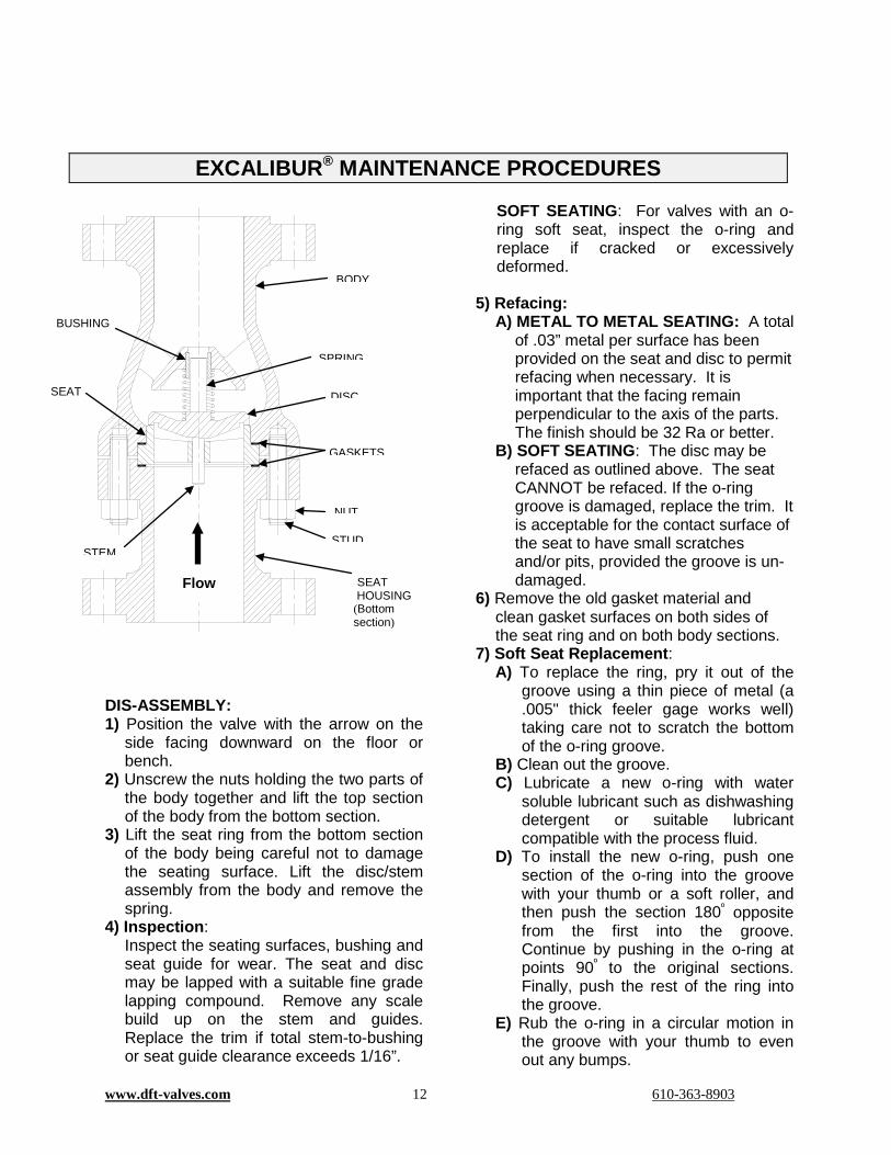
DIS-ASSEMBLY: 1) Position the valve with the arrow on the
side facing downward on the floor or bench.
2) Unscrew the nuts holding the two parts of the body together and lift the top section of the body from the bottom section.
3) Lift the seat ring from the bottom section of the body being careful not to damage the seating surface. Lift the disc/stem assembly from the body and remove the spring.
4) Inspection: Inspect the seating surfaces, bushing and seat guide for wear. The seat and disc may be lapped with a suitable fine grade lapping compound. Remove any scale build up on the stem and guides. Replace the trim if total stem-to-bushing or seat guide clearance exceeds 1/16”.
SOFT SEATING: For valves with an o-ring soft seat, inspect the o-ring and replace if cracked or excessively deformed.
5) Refacing: A) METAL TO METAL SEATING: A total
of .03” metal per surface has been provided on the seat and disc to permit refacing when necessary. It is important that the facing remain perpendicular to the axis of the parts. The finish should be 32 Ra or better.
B) SOFT SEATING: The disc may be refaced as outlined above. The seat CANNOT be refaced. If the o-ring groove is damaged, replace the trim. It is acceptable for the contact surface of the seat to have small scratches and/or pits, provided the groove is un-damaged.
6) Remove the old gasket material and clean gasket surfaces on both sides of the seat ring and on both body sections.
7) Soft Seat Replacement: A) To replace the ring, pry it out of the
groove using a thin piece of metal (a .005" thick feeler gage works well) taking care not to scratch the bottom of the o-ring groove.
B) Clean out the groove. C) Lubricate a new o-ring with water
soluble lubricant such as dishwashing detergent or suitable lubricant compatible with the process fluid.
D) To install the new o-ring, push one section of the o-ring into the groove with your thumb or a soft roller, and then push the section 180º opposite from the first into the groove. Continue by pushing in the o-ring at points 90º to the original sections. Finally, push the rest of the ring into the groove.
E) Rub the o-ring in a circular motion in the groove with your thumb to even out any bumps.
EXCALIBUR® MAINTENANCE PROCEDURES
SEAT HOUSING (Bottom section)
Flow
BODY
BUSHING
DISC SEAT
GASKETS
SPRING
STEM
NUT
STUD
www.dft-valves.com 13 610-363-8903
EXCALIBUR® MAINTENANCE PROCEDURES
RE-ASSEMBLY: 1) Insert the spring into the spring retainer in
the bottom body section. 2) Insert the disc/stem assembly into the
disc guide of the bottom body section insuring that the seating surface faces upward.
3) Place a new gasket on the bottom body section.
4) Place the seat ring (seating surface downward) on the gasket.
5) Place a new gasket on top of the seat ring.
6) Place the top body section onto the bottom body section.
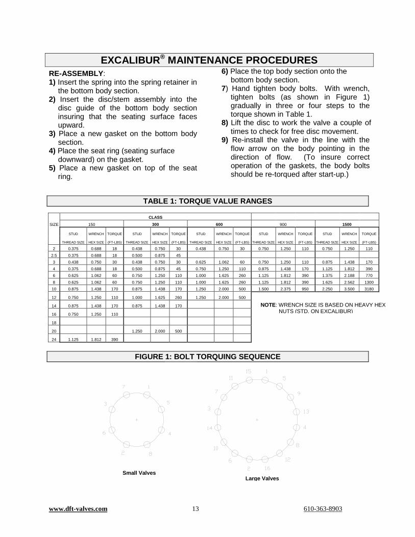
7) Hand tighten body bolts. With wrench, tighten bolts (as shown in Figure 1) gradually in three or four steps to the torque shown in Table 1.
8) Lift the disc to work the valve a couple of times to check for free disc movement.
9) Re-install the valve in the line with the flow arrow on the body pointing in the direction of flow. (To insure correct operation of the gaskets, the body bolts should be re-torqued after start-up.)
TABLE 1: TORQUE VALUE RANGES
CLASS
SIZE 150 300 600 900 1500
STUD WRENCH TORQUE STUD WRENCH TORQUE STUD WRENCH TORQUE STUD WRENCH TORQUE STUD WRENCH TORQUE
THREAD SIZE HEX SIZE (FT-LBS) THREAD SIZE HEX SIZE (FT-LBS) THREAD SIZE HEX SIZE (FT-LBS) THREAD SIZE HEX SIZE (FT-LBS) THREAD SIZE HEX SIZE (FT-LBS)
2 0.375 0.688 18 0.438 0.750 30 0.438 0.750 30 0.750 1.250 110 0.750 1.250 110 2.5 0.375 0.688 18 0.500 0.875 45 3 0.438 0.750 30 0.438 0.750 30 0.625 1.062 60 0.750 1.250 110 0.875 1.438 170 4 0.375 0.688 18 0.500 0.875 45 0.750 1.250 110 0.875 1.438 170 1.125 1.812 390 6 0.625 1.062 60 0.750 1.250 110 1.000 1.625 260 1.125 1.812 390 1.375 2.188 770 8 0.625 1.062 60 0.750 1.250 110 1.000 1.625 260 1.125 1.812 390 1.625 2.562 1300
10 0.875 1.438 170 0.875 1.438 170 1.250 2.000 500 1.500 2.375 950 2.250 3.500 3180
12 0.750 1.250 110 1.000 1.625 260 1.250 2.000 500 14 0.875 1.438 170 0.875 1.438 170 16 0.750 1.250 110 18 20 1.250 2.000 500 24 1.125 1.812 390
FIGURE 1: BOLT TORQUING SEQUENCE
Small Valves Large Valves
NOTE: WRENCH SIZE IS BASED ON HEAVY HEX NUTS (STD. ON EXCALIBUR)
www.dft-valves.com 14 610-363-8903
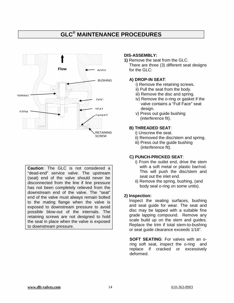
Caution: The GLC is not considered a “dead-end” service valve. The upstream (seat) end of the valve should never be disconnected from the line if line pressure has not been completely relieved from the downstream end of the valve. The “seat” end of the valve must always remain bolted to the mating flange when the valve is exposed to downstream pressure to avoid possible blow-out of the internals. The retaining screws are not designed to hold the seat in place when the valve is exposed to downstream pressure.
DIS-ASSEMBLY: 1) Remove the seat from the GLC.
There are three (3) different seat designs for the GLC:
A) DROP-IN SEAT:
i) Remove the retaining screws. ii) Pull the seat from the body. iii) Remove the disc and spring. iv) Remove the o-ring or gasket if the
valve contains a “Full Face” seat design.
v) Press out guide bushing (interference fit).
B) THREADED SEAT:
i) Unscrew the seat. ii) Removed the disc/stem and spring. iii) Press out the guide bushing
(interference fit). C) PUNCH-PRICKED SEAT:
i) From the outlet end, drive the stem with a soft metal or plastic bar/rod. This will push the disc/stem and seat out the inlet end.
ii) Remove the spring, bushing, (and body seal o-ring on some units).
2) Inspection:
Inspect the seating surfaces, bushing and seat guide for wear. The seat and disc may be lapped with a suitable fine grade lapping compound. Remove any scale build up on the stem and guides. Replace the trim if total stem-to-bushing or seat guide clearance exceeds 1/16”. SOFT SEATING: For valves with an o-ring soft seat, inspect the o-ring and replace if cracked or excessively deformed.
GLC® MAINTENANCE PROCEDURES
Flow
BODY
BUSHING
SPRING DISC
STEM SEAT
GASKET
RETAINING SCREW

www.dft-valves.com 15 610-363-8903
GLC® MAINTENANCE PROCEDURES
3) Refacing: A) METAL TO METAL SEATING:
A total of .03” metal per surface has been provided on the seat and disc to permit refacing when necessary. It is important that the facing remain perpendicular to the axis of the parts. The finish should be 32 Ra or better.
B) SOFT SEATING:
The disc may be refaced as outlined above. The seat CANNOT be refaced. If the o-ring groove is damaged, replace the trim. It is acceptable for the contact surface of the seat to have small scratches and/or pits, provided the groove is un-damaged.
4) Soft Seat Replacement:
A) To replace the ring, pry it out of the groove using a thin piece of metal (a .005" thick feeler gage works well) taking care not to scratch the bottom of the o-ring groove.
B) Clean out the groove. C) Lubricate a new o-ring with water
soluble lubricant such as dishwashing detergent or suitable lubricant compatible with the process fluid.
D) To install the new o-ring, push one section of the o-ring into the groove with your thumb or a soft roller, then push the section 180º opposite from the first into the groove. Continue by pushing in the o-ring at points 90º to the original sections. Finally, push the rest of the ring into the groove.
E) Rub the o-ring in a circular motion in the groove with your thumb to even-out any bumps.
RE-ASSEMBLY: 1) Seat Installation
Install the seat into the valve body. NOTE: There are three (3) different seat designs:
A) DROP-IN SEAT: i) Press bushing into body. ii) Place spring, (large end first for
conical springs) into the body. iii) Insert the disc/stem assembly. iv) Install the body o-ring or gasket
if the valve contains a “Full Face” seat.
v) Lower the seat into the body and install the retaining screws.
B) THREADED SEAT:
i) Press bushing into the body. ii) Place spring, (large end first for
conical springs) into the body. iii) Insert the disc/stem assembly. iv) Coat the seat threads with anti-
seize compound and screw in the seat until locked.
C) PUNCH-PRICKED SEAT:
i) Press bushing into body. ii) Place spring, (large end first for
conical springs) into the body. iii) Insert the disc/stem assembly. iv) Install the body o-ring (if
required). v) Press in seat until bottomed. (If
seat is not tight, remove and re-stake the O.D. of the seat with a sharp point punch at 3 or 4 places to create interference points, then press seat back into body.)
2) Stroke the disc to work the valve a couple of times to check for free disc movement.
3) Re-install the valve in the line with the flow arrow on the body pointing in the direction of flow.

www.dft-valves.com 16 610-363-8903
PDC® MAINTENANCE PROCEDURES
US Patent # 4,766,929 #4,693,270 Caution: The PDC is not considered a “dead-end” service valve. The upstream (seat) end of the valve should never be disconnected from the line if line pressure has not been completely relieved from the downstream end of the valve. The “seat” end of the valve must always remain bolted to the mating flange when the valve is exposed to downstream pressure to avoid possible blow-out of the internals. The retaining screws are not designed to hold the seat in place when the valve is exposed to downstream pressure and disconnected from the pipe.
DIS-ASSEMBLY: 1) Remove the seat from the PDC.
There are two (2) different seat designs for the PDC: A) DROP-IN SEAT:
i) Remove the retaining screws. ii) Push out the disc, disc guide and seat
as an assembly. iii) Remove the o-ring if the valve
contains a “Full Face” seat design.
B) PUNCH-PRICKED SEAT: i) From the outlet end, drive the stem with
a soft metal or plastic bar/rod. This will push the disc, disc guide and seat as an assembly out the inlet end.
ii) Remove the o-ring (on some models). 2) Slide the Disc off the Disc Guide. 3) Remove guide ring and seal ring. Take care
not to scratch the groove surfaces. It may be necessary to destroy the seal ring to remove.
4) Remove the spring retainer:
A) 2” through 8: The retainer is threaded-in and the threads are then staked to lock them in place. i) Grind away the damaged threads where
they are staked. ii) Stick two (2) 1/8” rods (or drill bits) in the
two (2) holes. iii) With a large screwdriver wedged
between the rods, unscrew the retainer.
B) 10” and larger The retainer is dropped-in, then the edge of the bore is staked to lock it in. i) Grind away the upset metal. ii) Push the check disc and retainer out.
5) Clean the Disc, Disc Guide and check ball (or the check disc on 10” and larger valves) with a suitable solvent.
6) Inspection:
A) Inspect the bore of the disc; replace if scored.
B) Inspect the Orifice in the Disc Guide; clean out if dirty or clogged.
C) Inspect the Bushing in the Body for excessive wear; if I.D. of Bushing is visibly out-of-round due to wear on one side or if stem-to-bushing or seat guide clearance exceeds 1/16" remove it by pressing it out.
D) Remove any scale build-up on stem and disc bore.
Flow
BODY BUSHING
SPRING
SPRING RETAINER
BALL CHECK
DISC
ORIFICE PLUG
SEAL RING
GUIDE RING
DISC GUIDE
SEAT
NUT RETAINING SCREW
O-RING

www.dft-valves.com 17 610-363-8903
PDC® MAINTENANCE PROCEDURES SOFT SEATING: For valves with an o-ring soft seat, inspect the o-ring and replace if cracked or excessively deformed. 7) Refacing:
A) METAL TO METAL SEATING: A total of .03” metal per surface has been provided on the seat and disc to permit refacing when necessary. It is important that the facing remain concentric to the axis of the parts. The finish should be 32 Ra or better.
B) SOFT SEATING: The disc may be refaced as outlined above. The seat CANNOT be refaced. If the o-ring groove is damaged, replace the trim. It is acceptable for the contact surface of the seat to have small scratches and/or pits, provided the groove is un-damaged.
8) Soft Seat Replacement:
A) To replace the ring, pry it out of the groove using a thin piece of metal (a .005" thick feeler gage works well) taking care not to scratch the bottom of the o-ring groove.
B) Clean out the groove. C) Lubricate a new o-ring with water
soluble lubricant such as dishwashing detergent or suitable lubricant compatible with the process fluid.
D) To install the new o-ring, push one section of the o-ring into the groove with your thumb or a soft roller, then push the section 180º opposite from the first into the groove. Continue by pushing in the o-ring at points 90º to the original sections. Finally, push the rest of the ring into the groove.
E) Rub the o-ring in a circular motion in the groove with your thumb to even-out any bumps.
RE-ASSEMBLY: 1) Reinstall the check ball (or the check disc
on 10” and larger valves), spring and the spring retainer into the disc guide.
2) Stake the outside of the spring retainer
at four (4) places to lock it in place. 3) Install new guide ring. Coat new seal
ring with general purpose lithium grease and install on Disc Guide with the open side of the “U” facing up toward the compression chamber. The seal ring will fit tightly over the Disc Guide, so be careful not to distort it or damage its sealing edges.
4) Seat Installation
A) DROP-IN SEAT: i) Press bushing into body. ii) Place spring, (large end first for
conical springs) into the body. iii) Install the body o-ring if the valve
contains a “Full Face” seat. iv) Apply a coating of grease to the
seal ring and guide ring. v) Lower the disc/disc guide/seat
assembly into the body and install the retaining screws.
B) PUNCH-PRICKED SEAT:
i) Press bushing into body. ii) Place spring, (large end first for
conical springs) into the body. iii) Install the body o-ring (If required). iv) Apply a coating of grease to the
seal ring and guide ring. v) Re-stake the O.D. of the seat with a
sharp point punch at 3 or 4 places to create interference points, then press the disc/disc guide/seat assembly into the body.
5) Stroke the disc to work the valve a couple
of times to check for free disc movement. The valve should close in the horizontal orientation.
6) Re-install the valve in the line with the
flow arrow on the body pointing in the direction of flow.
www.dft-valves.com 18 610-363-8903
SCV® MAINTENANCE PROCEDURES
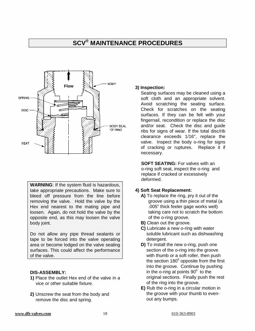
WARNING: If the system fluid is hazardous, take appropriate precautions. Make sure to bleed off pressure from the line before removing the valve. Hold the valve by the Hex end nearest to the mating pipe and loosen. Again, do not hold the valve by the opposite end, as this may loosen the valve body joint. Do not allow any pipe thread sealants or tape to be forced into the valve operating area or become lodged on the valve sealing surfaces. This could affect the performance of the valve. DIS-ASSEMBLY: 1) Place the outlet Hex end of the valve in a
vice or other suitable fixture. 2) Unscrew the seat from the body and
remove the disc and spring.
3) Inspection:
Seating surfaces may be cleaned using a soft cloth and an appropriate solvent. Avoid scratching the seating surface. Check for scratches on the seating surfaces. If they can be felt with your fingernail, recondition or replace the disc and/or seat. Check the disc and guide ribs for signs of wear. If the total disc/rib clearance exceeds 1/16", replace the valve. Inspect the body o-ring for signs of cracking or ruptures. Replace it if necessary.
SOFT SEATING: For valves with an o-ring soft seat, inspect the o-ring and replace if cracked or excessively deformed.
4) Soft Seat Replacement: A) To replace the ring, pry it out of the
groove using a thin piece of metal (a .005" thick feeler gage works well) taking care not to scratch the bottom of the o-ring groove.
B) Clean out the groove. C) Lubricate a new o-ring with water
soluble lubricant such as dishwashing detergent.
D) To install the new o-ring, push one section of the o-ring into the groove with thumb or a soft roller, then push the section 1800 opposite from the first into the groove. Continue by pushing in the o-ring at points 900 to the original sections. Finally push the rest of the ring into the groove.
E) Rub the o-ring in a circular motion in the groove with your thumb to even-out any bumps.
Flow
www.dft-valves.com 19 610-363-8903
SCV® MAINTENANCE PROCEDURES RE-ASSEMBLY: 1) Place the spring into the body, large end
first, then the disc with the side marked “spring side” against the disc.
2) Clean all the threads of the seat and coat
with an anti-seize compound. 3) Install the new body o-ring in the thread
undercut of the seat. 4) While holding the disc down in the body,
and compressing the spring, screw the seat into the body.
5) Tighten to 200 ft-lbs. for 1" and larger units, 100 ft-lbs. for 3/4" and 1/2" units, and 50 ft-lbs. for 1/4".
6) Lift the disc to work the valve a couple of
times to check for free disc movement. 7) Reinstall the valve in the line with the
flow arrow on the body pointing in the direction of flow.
Caution: Do not allow any pipe thread
sealants or tape to be forced into the valve operating area or become lodged on the valve sealing surfaces.
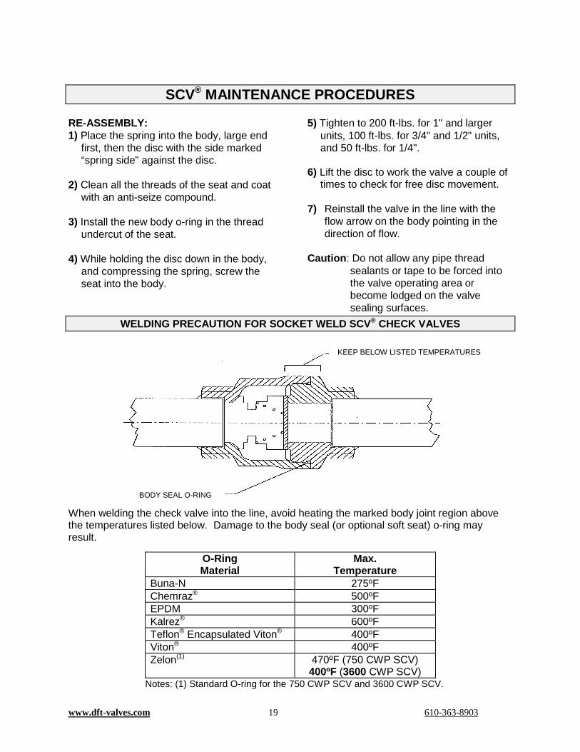
WELDING PRECAUTION FOR SOCKET WELD SCV® CHECK VALVES
When welding the check valve into the line, avoid heating the marked body joint region above the temperatures listed below. Damage to the body seal (or optional soft seat) o-ring may result.
O-Ring Material
Max. Temperature
Buna-N 275ºF Chemraz® 500ºF EPDM 300ºF Kalrez® 600ºF Teflon® Encapsulated Viton® 400ºF Viton® 400ºF Zelon(1) 470ºF (750 CWP SCV)
400ºF (3600 CWP SCV) Notes: (1) Standard O-ring for the 750 CWP SCV and 3600 CWP SCV.
KEEP BELOW LISTED TEMPERATURES
BODY SEAL O-RING

www.dft-valves.com 20 610-363-8903
SCV-R™ MAINTENANCE PROCEDURES
WARNING: If the system fluid is hazardous, take appropriate precautions. CAUTION: The spring cracking pressure inside the valve can range from 1 psi to 25 psi. Use caution with disassembly. Make sure to bleed off pressure from the line before removing the valve. Hold the valve by the Hex end nearest to the mating pipe and loosen. Again, do not hold the valve by the opposite end, as this may loosen the valve body joint. Do not allow any pipe thread sealants or tape to be forced into the valve operating area or become lodged on the valve sealing surfaces. This could affect the performance of the valve. DIS-ASSEMBLY: 1) Place the outlet Hex end of the valve in a
vice or other suitable fixture oriented vertically.
2) Unscrew the seat from the body and remove the disc, spring, spring retainer, shim(s) if included, and body O-ring.
3) Inspection:
Seating surfaces may be cleaned using a soft cloth and an appropriate solvent. Avoid scratching the seating surface. Check for scratches on the seating surfaces. If they can be felt with your fingernail, recondition or replace the disc and/or seat. Check the disc and guide ribs for signs of wear. If the total disc/rib clearance exceeds 1/16", replace the valve. Inspect the body o-ring for signs of cracking or ruptures. Replace it if necessary.
SOFT SEATING: For valves with an o-ring soft seat, inspect the o-ring and replace if cracked or excessively deformed.
4) Soft Seat Replacement: A) To replace the ring, pry it out of the
groove using a thin piece of metal (a .005" thick feeler gage works well) taking care not to scratch the inside wall of the o-ring groove.
B) Clean out the groove. C) Lubricate a new o-ring with water
soluble lubricant such as dishwashing detergent.
D) To install the new o-ring, push one section of the o-ring into the groove with thumb or a soft roller, then push the section 1800 opposite from the first into the groove. Continue by pushing in the o-ring at points 900 to the original sections. Finally push the rest of the ring into the groove.
E) Rub the o-ring in a circular motion in the groove with your thumb to even-out any bumps.
SEAT
BODY SEAL “O” RING DISC
SPRING
BODY SPRING RETAINER
SHIMS
www.dft-valves.com 21 610-363-8903
SCV-R™ MAINTENANCE PROCEDURES RE-ASSEMBLY: 1) With the body oriented vertically and the
outlet down, place the spring retainer into the body followed by the shim(s) if included.
2) Place the spring into the spring retainer. 3) Place the disc with the side marked
“spring side” against the spring. 4) Clean all the threads of the seat and coat
with an anti-seize compound. 5) Install the new body o-ring in the thread
undercut of the seat. 6) While holding the disc down in the body,
and compressing the spring, screw the seat into the body.
7) Tighten to 200 ft-lbs. for 1" and larger
units, 100 ft-lbs. for 3/4" and 1/2" units, and 50 ft-lbs. for 1/4".
8) Lift the disc to work the valve a couple of times to check for free disc movement.
9) Reinstall the valve in the line with the flow arrow on the body pointing in the direction of flow.
Caution: Do not allow any pipe thread
sealants or tape to be forced into the valve operating area or become lodged on the valve sealing surfaces.
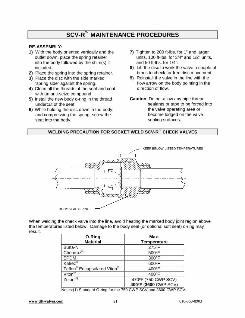
WELDING PRECAUTION FOR SOCKET WELD SCV-R™ CHECK VALVES
When welding the check valve into the line, avoid heating the marked body joint region above the temperatures listed below. Damage to the body seal (or optional soft seat) o-ring may result.
O-Ring Material
Max. Temperature
Buna-N 275ºF Chemraz® 500ºF EPDM 300ºF Kalrez® 600ºF Teflon® Encapsulated Viton® 400ºF Viton® 400ºF Zelon(1) 470ºF (750 CWP SCV)
400ºF (3600 CWP SCV) Notes:(1) Standard O-ring for the 750 CWP SCV and 3600 CWP SCV.
KEEP BELOW LISTED TEMPERATURES
BODY SEAL O-RING
www.dft-valves.com 22 610-363-8903
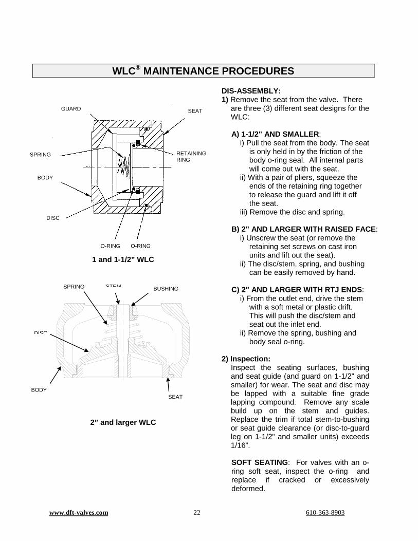
1 and 1-1/2” WLC
2” and larger WLC
DIS-ASSEMBLY: 1) Remove the seat from the valve. There
are three (3) different seat designs for the WLC:
A) 1-1/2" AND SMALLER:
i) Pull the seat from the body. The seat is only held in by the friction of the body o-ring seal. All internal parts will come out with the seat.
ii) With a pair of pliers, squeeze the ends of the retaining ring together to release the guard and lift it off the seat.
iii) Remove the disc and spring.
B) 2" AND LARGER WITH RAISED FACE: i) Unscrew the seat (or remove the
retaining set screws on cast iron units and lift out the seat).
ii) The disc/stem, spring, and bushing can be easily removed by hand.
C) 2" AND LARGER WITH RTJ ENDS:
i) From the outlet end, drive the stem with a soft metal or plastic drift. This will push the disc/stem and seat out the inlet end.
ii) Remove the spring, bushing and body seal o-ring.
2) Inspection:
Inspect the seating surfaces, bushing and seat guide (and guard on 1-1/2" and smaller) for wear. The seat and disc may be lapped with a suitable fine grade lapping compound. Remove any scale build up on the stem and guides. Replace the trim if total stem-to-bushing or seat guide clearance (or disc-to-guard leg on 1-1/2" and smaller units) exceeds 1/16”. SOFT SEATING: For valves with an o-ring soft seat, inspect the o-ring and replace if cracked or excessively deformed.
WLC® MAINTENANCE PROCEDURES
GUARD SEAT
RETAINING RING
O-RING O-RING
DISC
SPRING
BODY
BUSHING
SEAT BODY
SPRING STEM
DISC

www.dft-valves.com 23 610-363-8903
WLC® MAINTENANCE PROCEDURES 3) Refacing:
A) METAL TO METAL SEATING: A total of .03” metal per surface has been provided on the seat and disc to permit refacing when necessary. It is important that the facing remain perpendicular to the axis of the parts. The finish should be 32 Ra or better.
B) SOFT SEATING: The disc may be
refaced as outlined above. The seat CANNOT be refaced. If the o-ring groove is damaged, replace the trim. It is acceptable for the contact surface of the seat to have small scratches and/or pits, provided the groove is un-damaged.
4) Soft Seat Replacement:
A) To replace the ring, pry it out of the groove using a thin piece of metal (a .005" thick feeler gage works well) taking care not to scratch the bottom of the o-ring groove.
B) Clean out the groove. Lubricate a new o-ring with water soluble lubricant such as dishwashing detergent or suitable lubricant compatible with the process fluid.
C) To install the new o-ring, push one section of the o-ring into the groove with your thumb or a soft roller, then push the section 1800 opposite from the first into the groove. Continue by pushing in the o-ring at points 900 to the original sections. Finally, push the rest of the ring into the groove.
D) Rub the o-ring in a circular motion in the groove with your thumb to even-out any bumps.
RE-ASSEMBLY: 1) Seat Installation
There are three (3) different seat designs for the WLC:
A)1-1/2" AND SMALLER:
i) Place retaining ring in groove of seat.
ii) Place spring, small end first, onto guard spring hub.
iii) Position the disc over the spring and between the four guard legs.
iv) While holding the disc and spring in the guard with one hand, compress the retaining ring with suitable pliers into the seat groove with the other, then position the disc/spring/guard over the seat with the notches in the guard legs aligned with the retaining ring and release the retaining ring, locking the guard onto the seat.
v) Lift the disc to work the valve a couple of times to check for free disc movement.
B) 2" AND LARGER WITH RAISED FACE:
i) Install the guide bushing. ii) Place the spring (small end for
conical springs) on the guide bushing shoulder.
iii) Insert the disc/stem assembly. iv) Coating the seat threads with anti-
seize compound is recommended. Then screw in seat until locked. (Drop in the seat and re-install the retaining set screws for cast iron units.)
C) 2" AND LARGER WITH RTJ ENDS:
i) Install the guide bushing. ii) Place the small end of the spring on
the guide bushing shoulder. iii) Insert the disc/stem assembly. iv) Install the body o-ring. v) Press in seat until bottomed. (If
seat is not tight, remove and re-stake the O.D. of the seat with a sharp point punch at 3 or 4 places to create interference points, then press seat back into body.)
2) Re-install the valve in the line with the flow arrow on the body pointing in the direction of flow.
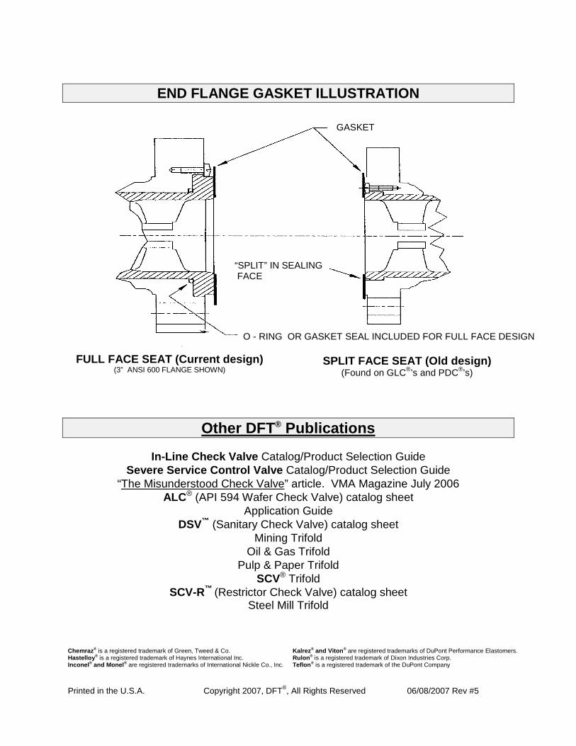
END FLANGE GASKET ILLUSTRATION
Other DFT® Publications
In-Line Check Valve Catalog/Product Selection Guide Severe Service Control Valve Catalog/Product Selection Guide
“The Misunderstood Check Valve” article. VMA Magazine July 2006 ALC® (API 594 Wafer Check Valve) catalog sheet
Application Guide DSV™ (Sanitary Check Valve) catalog sheet
Mining Trifold Oil & Gas Trifold
Pulp & Paper Trifold SCV® Trifold
SCV-R™ (Restrictor Check Valve) catalog sheet Steel Mill Trifold
Chemraz® is a registered trademark of Green, Tweed & Co. Hastelloy® is a registered trademark of Haynes International Inc. Inconel® and Monel® are registered trademarks of International Nickle Co., Inc.
Kalrez® and Viton® are registered trademarks of DuPont Performance Elastomers. Rulon® is a registered trademark of Dixon Industries Corp. Teflon® is a registered trademark of the DuPont Company
Printed in the U.S.A. Copyright 2007, DFT®, All Rights Reserved 06/08/2007 Rev #5
FULL FACE SEAT (Current design) (3” ANSI 600 FLANGE SHOWN)
SPLIT FACE SEAT (Old design) (Found on GLC®’s and PDC®’s)
O - RING OR GASKET SEAL INCLUDED FOR FULL FACE DESIGN
“SPLIT” IN SEALING FACE
GASKET