dfS20/dfS21/dfS22/dfS25 incremental Encoders · Ordering code for 2 inch size square lange and...
24
High-resolution factory-conigured and user programmable encoders for complex applications and high operational demands Product information dfS20/dfS21/dfS22/dfS25 incremental Encoders
Transcript of dfS20/dfS21/dfS22/dfS25 incremental Encoders · Ordering code for 2 inch size square lange and...

High-resolution factory-conigured and user programmable encoders for complex applications and high operational demands
Pr
od
uc
t i
nf
or
ma
tio
n
dfS20/dfS21/dfS22/dfS25incremental Encoders

2
dfS20/dfS21/dfS22/dfS25 Incremental Encoders
Subject to change without notice8016309/2013.04.02d f S 2 X i n c r E m E n ta L E n c o d E r S | S i c K
Product descriptionThe DFS2x family of products are high-resolution incremental encoders that provide industry standard 2 and 2.5-inch mechanical interfaces and are available as factory-conigured or programmable devices. Factory-conigured encoders can be ordered with TTL, HTL, or open-collec-
tor outputs as well as integer resolutions from 1 to 65,536 counts per revolution. Programmable encoders allow the user to select the integer resolution and either
TTL or HTL outputs. DFS2x encoders incorporate rugged internal technology that allows them to operate over a wide temperature range and tolerate twice the shock & vibration levels of comparable encoders. The lexibility and reliability of these encoders allows you to conidently standardize on a single encoder platform for position sensing across a wide variety of applications while simultaneously reducing your spare part requirements.
at a glance • Compact 2-inch and 2.5-inch design • Integer resolutions from 1 to 65,536
counts per revolution. • Compatible with PGT-08-S PC based
programming tool. • User programmable DFS2x encoders
allow the user to conigure resolution, zero pulse phase, zero pulse position, and output electrical interface.
• Flange, hollow shaft, and blind hollow shaft options.
• M12 connector, MS connector, and lying lead cable connection options.
Your beneit
High-resolution factory-conigured programmable encoder for applications with mounting hole dimensions in inches
additional informationDetailed technical speciications . . . .3
Maximum revolution range. . . . . . . . . .5
Ordering information. . . . . . . . . . . . . . .6
Dimensional drawings . . . . . . . . . . . . .9
PIN and core assignment . . . . . . . . . 14
Accessories . . . . . . . . . . . . . . . . . . . . 15
UL certiication only valid for encod-
ers with cable and M12 connections
• Programmable DFS2x encoders sim-
plify machine designs by allowing the same model encoder to be used for different applications.
• Spare parts inventory requirements are reduced because a single pro-
grammable DFS2x encoder can be used across a variety of applications.
• Flexible electrical interface con-
igurations reduces the risk that the selected encoder will be incompatible with input electronics.
• High-resolution provides more precise positioning for applications that require high accuracy.
• Wide operating temperature range and high tolerance of shock and vibration reduces downtime on machinery.

3
dfS20/dfS21/dfS22/dfS25Incremental Encoders
d f S 2 X i n c r E m E n ta L E n c o d E r S | S i c K8016309/2013.04.02
Subject to change without notice
Detailed technical speciications
Performancenumber of lines per revolution 1 to 65, 536 Integer
measuring step 90° electrical / number of lines
reference signal
Number 1
Phase Electrical Factory conigured 90° or 180°
Phase Mechanical Programmable 1°-359°
Error limits ± 0.03°
measuring step deviation
Number of lines 1 ... 99 ± 0.04°
Number of lines 100 ... 10000 ± 0.008°
Number of lines > 10000 ± 0.002°
1) See maximum revolution range on page 5.
Interfaces
Supply Voltage/output type 4.5-5.5 Volt DC, TTL/RS422 Differential Line Driver
8-30 Volt DC, TTL/RS422 Differential Line Driver
8-30 Volt DC, HTL/Push-Pull
8-30 Volt DC, Open Collector
4.75-30 Volt DC, User Programmable: TTL/RS422 Differential Line Driver or HTL/Push-Pull1)
initialization time
After Power-on 40 ms
After Zero-Set Max. 30 ms
Zero-Set input2) Active High3)
1) Factory default set to TTL/RS422 Differential Line Driver2) The Zero-Set function is not available with 6-pin MS connector or M12 connector options3) When activated, the Zero-Set function assigns the zero marker pulse location to the encoder's current shaft position. To activate the Zero-Set function, the input must be low or open for at least 1 second and then be driven high for at least 250 msec. The high signal must be at least 0.43 times the encoder supply voltage.

4
dfS20/dfS21/dfS22/dfS25 Incremental Encoders
Subject to change without notice8016309/2013.04.02d f S 2 X i n c r E m E n ta L E n c o d E r S | S i c K
Mechanics/Electrical systemShaft diameter
Square and Servo Mount Flange 1/4 inch with lat, 3/8 in with lat, and 10 mm with lat
Blind and Through Hollow Shaft 3/8 inch and 1/2 inch
Weight
Face mount lange, servo lange 0.4 kg (MS connector)
Blind hollow shaft, through hollow shaft 0.3 kg (M12 connector)
rotor moment of inertia
Face mount lange, servo lange 15 gcm2
Blind hollow shaft, through hollow shaft 40 gcm2
max. output frequency
TTL/RS422 150 kHz
HTL/Push pull 820 kHz
Open Collector 820 kHz
operating speed 1)
Square lange, servo mount 9,000 rpm
Blind hollow shaft, through hollow shaft 6,000 rpm
angular acceleration 5 x 10⁵ rad/s2
operating torque at 20 °c
Square lange, servo mount 0.3 Ncm
Blind hollow shaft, through hollow shaft 0.6 Ncm
Start-up torque at 20 °c
Face mount lange, servo lange 0.5 Ncm
Blind hollow shaft, through hollow shaft 0.8 Ncm
Permissible shaft loading
Square lange, servo mount 80 N (radial) 40 N (axial)
Permissible shaft movement of the drive element static/dynamic
Blind hollow shaft, through hollow shaft ± 0.3/± 0.05 mm (radial) ± 0.5/± 0.1 mm (axial)
Bearing lifetime 3.6 x 10⁹ revolutions
Load current
All output types 30 mA
operating current with no load
Programmable Versions 75 mA
Pre-conigured Versions 50 mA
Power consumption with no load
All output types 0.7 W
reverse polarity protection
4.75-5.5 VDC Supply/TTL Differential Line Driver
Yes
8-30 VDC Suppy/TTL Differential Line Driver Yes
8-30 VDC Supply, HTL/Push-Pull Yes
8-30 VDC Supply, Open Collector Yes
4.75-30 VDC Supply, User Selectable: TTL Differential Line Driver or HTL/Push-Pull
Yes

5
dfS20/dfS21/dfS22/dfS25Incremental Encoders
d f S 2 X i n c r E m E n ta L E n c o d E r S | S i c K8016309/2013.04.02
Subject to change without notice
Short-circuit protection of the outputs
4.75-5.5 VDC Supply, TTL Differential Line Driver
Yes 1)
8-30 VDC Supply, TTL Differential Line Driver Yes 2)
8-30 VDC Supply, HTL/Push-Pull Yes 1)
8-30 VDC Supply, Open Collector Yes 1)
4.75-30 VDC Supply,User Programmable: TTL/RS422 Differential Line Driver or HTL/
Push-Pull
Yes 3)
MTTFd: mean time to dangerous failure 4) 330 years (EN ISO 13849-1)1) Channel-to-channel, channel-to-Us, or channel-to-GND short is permissible for 30s max.2) Channel-to-channel or channel-to-GND short is permissible for 30s max.3) HTL/Push-pull: Channel-to-channel, channel-to-Us, or channel-to-GND short is permissible for 30s max. TTL/RS422: Channel-to-channel or channel-to-GND short is permissible for 30s max. 4) This product is a standard product and does not constitute a safety component as deined in the Machinery Directive. Calculation based on nominal load of components, average ambient temperature 40 ºC, frequency of use 8760 h/a. All electronic failures are considered hazardous. For more information, see document no. 8015532.
EnvironmentWorking temperature range –30 … +80 °C
Storage temperature range (without packaging)
–40 … +100 °C
Permissible relative air humidity 1) 90 %
Emc 2) As per EN 61000-6-2 and EN 61000-6-3
resistance
Shock, non-repetitive per EN 60068-2-27 100 g/11 msec duration
Vibration per EN 60068-2-6 30 g/10-2,000 Hz
Enclosure rating as per iEc 60529 IP 651) Condensation on the optical scanner not permissible.2) When the mating connector is installed.
maximum Speed vs. Steps Per revolution
65536
61440
57344
53248
49152
45056
40960
36864
32768
28672
24576
20480
16384
12288
8192
4096
6
dfS20/dfS21/dfS22/dfS25 Incremental Encoders
Subject to change without notice8016309/2013.04.02d f S 2 X i n c r E m E n ta L E n c o d E r S | S i c K
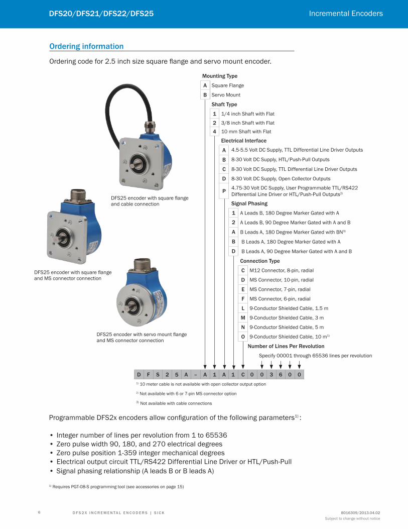
mounting type
a Square Flange
B Servo Mount
Shaft type
1 1/4 inch Shaft with Flat
2 3/8 inch Shaft with Flat
4 10 mm Shaft with Flat
Electrical interface
a 4.5-5.5 Volt DC Supply, TTL Differential Line Driver Outputs
B 8-30 Volt DC Supply, HTL/Push-Pull Outputs
c 8-30 Volt DC Supply, TTL Differential Line Driver Outputs
d 8-30 Volt DC Supply, Open Collector Outputs
P4.75-30 Volt DC Supply, User Programmable TTL/RS422 Differential Line Driver or HTL/Push-Pull Outputs2)
Signal Phasing
1 A Leads B, 180 Degree Marker Gated with A
2 A Leads B, 90 Degree Marker Gated with A and B
a B Leads A, 180 Degree Marker Gated with BN3)
B B Leads A, 180 Degree Marker Gated with A
d B Leads A, 90 Degree Marker Gated with A and B
connection type
c M12 Connector, 8-pin, radial
d MS Connector, 10-pin, radial
E MS Connector, 7-pin, radial
f MS Connector, 6-pin, radial
L 9-Conductor Shielded Cable, 1.5 m
m 9-Conductor Shielded Cable, 3 m
n 9-Conductor Shielded Cable, 5 m
o 9-Conductor Shielded Cable, 10 m1)
number of Lines Per revolution
Specify 00001 through 65536 lines per revolution
d f S 2 5 a – a 1 a 1 c 0 0 3 6 0 0
1) 10 meter cable is not available with open collector output option
2) Not available with 6 or 7-pin MS connector option
3) Not available with cable connections
ordering information
Ordering code for 2.5 inch size square lange and servo mount encoder.
Programmable DFS2x encoders allow coniguration of the following parameters1) :
• Integer number of lines per revolution from 1 to 65536 • Zero pulse width 90, 180, and 270 electrical degrees • Zero pulse position 1-359 integer mechanical degrees • Electrical output circuit TTL/RS422 Differential Line Driver or HTL/Push-Pull
• Signal phasing relationship (A leads B or B leads A)
1) Requires PGT-08-S programming tool (see accessories on page 15)
DFS25 encoder with square lange and cable connection
DFS25 encoder with square lange and MS connector connection
DFS25 encoder with servo mount lange and MS connector connection

7
dfS20/dfS21/dfS22/dfS25Incremental Encoders
d f S 2 X i n c r E m E n ta L E n c o d E r S | S i c K8016309/2013.04.02
Subject to change without notice
mounting type
a Square Flange
B Servo Mount
Shaft type
1 1/4 inch Shaft with Flat
2 3/8 inch Shaft with Flat
4 10 mm Shaft with Flat
Electrical interface
a 4.5-5.5 Volt DC Supply, TTL Differential Line Driver Outputs
B 8-30 Volt DC Supply, HTL/Push-Pull Outputs
c 8-30 Volt DC Supply, TTL Differential Line Driver Outputs
d 8-30 Volt DC Supply, Open Collector Outputs
P4.75-30 Volt DC Supply, User Programmable TTL/RS422 Differential Line Driver or HTL/Push-Pull Outputs2)
Signal Phasing
1 A Leads B, 180 Degree Marker Gated with A
2 A Leads B, 90 Degree Marker Gated with A and B
a B Leads A, 180 Degree Marker Gated with BN3)
B B Leads A, 180 Degree Marker Gated with A
d B Leads A, 90 Degree Marker Gated with A and B
connection type
c M12 Connector, 8-pin, radial
d MS Connector, 10-pin, radial
E MS Connector, 7-pin, radial
f MS Connector, 6-pin, radial
L 9-Conductor Shielded Cable, 1.5 m
m 9-Conductor Shielded Cable, 3 m
n 9-Conductor Shielded Cable, 5 m
o 9-Conductor Shielded Cable, 10 m1)
number of Lines Per revolution
Specify 00001 through 65536 lines per revolution
d f S 2 0 a – a 1 a 1 c 0 0 3 6 0 0
1) 10 meter cable is not available with open collector output option
2) Not available with 6 or 7-pin MS connector option
3) Not available with cable connections
Ordering code for 2 inch size square lange and servo mount encoder.
Programmable DFS2x encoders allow coniguration of the following parameters1) :
• Integer number of lines per revolution from 1 to 65536 • Zero pulse width 90, 180, and 270 electrical degrees • Zero pulse position 1-359 integer mechanical degrees • Electrical output circuit TTL/RS422 Differential Line Driver or HTL/Push-Pull
• Signal phasing relationship (A leads B or B leads A)
1) Requires PGT-08-S programming tool (see accessories on page 15)
DFS20 encoder with servo mount lange and cable connection
DFS20 encoder with square lange and MS connector connection
DFS20 encoder with servo mount lange and M12 connector connection

8
dfS20/dfS21/dfS22/dfS25 Incremental Encoders
DFS22 encoder with blind hollow shaft and cable connection
DFS21 encoder with through hollow shaft mount and M12 connector connection
Subject to change without notice8016309/2013.04.02d f S 2 X i n c r E m E n ta L E n c o d E r S | S i c K
mounting type
1 Through Hollow Shaft
2 Blind Hollow Shaftt
Shaft type
c 3/8 inch Metal Hollow Shaft
f 1/2 inch Metal Hollow Shaft
Electrical interface
a 4.5-5.5 Volt DC Supply, TTL Differential Line Driver Outputs
B 8-30 Volt DC Supply, HTL/Push-Pull Outputs
c 8-30 Volt DC Supply, TTL Differential Line Driver Outputs
d 8-30 Volt DC Supply, Open Collector Outputs
P4.75-30 Volt DC Supply, User Programmable TTL/RS422 Differential Line Driver or HTL/Push-Pull Outputs2)
Signal Phasing
1 A Leads B, 180 Degree Marker Gated with A
2 A Leads B, 90 Degree Marker Gated with A and B
a B Leads A, 180 Degree Marker Gated with BN3)
B B Leads A, 180 Degree Marker Gated with A
d B Leads A, 90 Degree Marker Gated with A and B
connection type
c M12 Connector, 8-pin, radial
L 9-Conductor Shielded Cable, 1.5 m
m 9-Conductor Shielded Cable, 3 m
n 9-Conductor Shielded Cable, 5 m
o 9-Conductor Shielded Cable, 10 m1)
number of Lines Per revolution
Specify 00001 through 65536 lines per revolution
d f S 2 1 a – K f a 1 c 0 0 3 6 0 01) 10 meter cable is not available with open collector output option
2) Not available with 6 or 7-pin MS connector option
3) Not available with cable connections
Ordering code for 2 inch size through hollow shaft and blind hollow shaft encoders.
Programmable DFS2x encoders allow coniguration of the following parameters1) :
• Integer number of lines per revolution from 1 to 65536• Zero pulse width 90, 180, and 270 electrical degrees• Zero pulse position 1-359 integer mechanical degrees • Electrical output circuit TTL/RS422 Differential Line Driver or HTL/Push-Pull• Signal phasing relationship (A leads B or B leads A)
1) Requires PGT-08-S programming tool (see accessories on page 15)

9
dfS20/dfS21/dfS22/dfS25Incremental Encoders
d f S 2 X i n c r E m E n ta L E n c o d E r S | S i c K8016309/2013.04.02
Subject to change without notice
dimensional drawings
DFS25A square lange mount, radial connector outlet M12 and MS, cable outlet.66
.68
2.63
66.682.63
52.392.06
52.3
92.
06
3X 8-32 UNC 4.83 0.19EQUALLY SPACED
47.631.875
4X 5.60 0.22 THRU
SQUARE FLANGE
28.301.11
6.350.25
B
31.7
0 ±0
.03
1.24
8 ±0
.001
50 1.97
90.35
19.050.75
63.5
02.
50
M12X1 CONNECTOR38.50
1.52
C
MIL CONNECTOR
28.301.11
55.
732.
19
PER
PART
NUM
BER
50 1.97
CABLE
4.350.17
29.84 ±0.641.17 ±0.03
A
SHAFT OPTIONSNOMINAL SHAFT "A" FLAT DIM "B"
1/4" 6.327/6.312[.2491/.2485] 5.5[.22]3/8" 9.507/9.492[.3743/.3737] 8.5[.33]
10MM 9.977/9.962[.3928/.3922] 9[.35]
MIL CONNECTOR OPTIONSTYPE DIM "C"6 PIN 63.9[2.52]7 PIN 63.9[2.52]
10 PIN 69.5[2.74]
All dimensions in mm (inches)

10
dfS20/dfS21/dfS22/dfS25 Incremental Encoders
Subject to change without notice8016309/2013.04.02d f S 2 X i n c r E m E n ta L E n c o d E r S | S i c K
DFS25A servo lange mount, radial connector outlet M12 and MS, cable outlet.
3X 8-32 UNC 4.8 0.19EQUALLY SPACED
47.631.875
SERVO FLANGE
2.540.10
63.5
02.
50 58.6
72.
31 B
2.540.10
1.270.05
28.301.11
50 1.97
31.7
0 ±0
.03
1.24
8 ±0
.001
90.35
19.050.75
63.5
02.
50
M12X1 CONNECTOR
C
38.501.52
MIL CONNECTOR
PER
PART
NUM
BER
50 1.97
5
5.73
2.19
28.301.11
CABLE
A
4.350.17
29.84 ±0.641.17 ±0.03
SHAFT OPTIONSNOMINAL SHAFT "A" FLAT DIM "B"
1/4" 6.327/6.312[.2491/.2485] 5.5[.22]3/8" 9.507/9.492[.3743/.3737] 8.5[.33]
10MM 9.977/9.962[.3928/.3922] 9[.35]
MIL CONNECTOR OPTIONSTYPE DIM "C"6 PIN 63.9[2.52]7 PIN 63.9[2.52]
10 PIN 69.4[2.73]
All dimensions in mm (inches)

11
dfS20/dfS21/dfS22/dfS25Incremental Encoders
d f S 2 X i n c r E m E n ta L E n c o d E r S | S i c K8016309/2013.04.02
Subject to change without notice
DFS20A square lange mount, radial connector outlet M12 and MS, cable outlet.
52.4
2.06
52.42.06
44.51.75
44.5
1.75
4X 4 0.16 THRU
SQUARE FLANGE
28.31.11
7.60.30
B
31.7
0 ±0
.03
1.24
8 ±0
.001
44 1.73
90.35
50.8
2.00
M12X1 CONNECTOR
49
.71.
96
PER
PART
NUM
BER
50 1.97
28.3
1.11
CABLE
38.51.52
C
180.71
MIL CONNECTOR
3.10.12
19.1 ±0.50.75 ±0.02
A
SHAFT OPTIONSNOMINAL SHAFT "A" FLAT DIM "B"
1/4" 6.327/6.312[.2491/.2485] 5.5[.22]3/8" 9.507/9.492[.3743/.3737] 8.5[.33]
10MM 9.977/9.962[.3928/.3922] 9[.35]
MIL CONNECTOR OPTIONSTYPE DIM "C"6 PIN 63.9[2.52]7 PIN 63.9[2.52]
10 PIN 69.4[2.73]
All dimensions in mm (inches)

12
dfS20/dfS21/dfS22/dfS25 Incremental Encoders
Subject to change without notice8016309/2013.04.02d f S 2 X i n c r E m E n ta L E n c o d E r S | S i c K
DFS20A servo lange mount, radial connector outlet M12 and MS, cable outlet.
29.
191.
15
29.191.15
38.101.50
421.65
4X 10-32 UNF 5.59 0.22
3X 4-40 UNC 5.59 0.22EQUALLY SPACED
3X M4x0.7 - 6H 5.59 0.22EQUALLY SPACED
SERVO FLANGE
2.540.10
2.540.10
2.540.10
50.8
02.
00 46.9
91.
85 B
31.7
0 ±0
.03
1.24
8 ±0
.001
44 1.73
28.301.11
90.35
50.8
02.
00
M12X1 CONNECTOR
C
180.71
38.501.52
MIL CONNECTOR
49.
731.
96
PER
PART
NUM
BER
50 1.97
28.301.11
CABLE
A
19.05 ±0.510.75 ±0.02
3.080.12
SHAFT OPTIONSNOMINAL SHAFT "A" FLAT DIM "B"
1/4" 6.327/6.312[.2491/.2485] 5.5[.22]3/8" 9.507/9.492[.3743/.3737] 8.5[.33]
10MM 9.977/9.962[.3928/.3922] 9[.35]
MIL CONNECTOR OPTIONSTYPE DIM "C"6 PIN 63.9[2.52]7 PIN 63.9[2.52]
10 PIN 69.4[2.73]
All dimensions in mm (inches)

13
dfS20/dfS21/dfS22/dfS25Incremental Encoders
d f S 2 X i n c r E m E n ta L E n c o d E r S | S i c K8016309/2013.04.02
Subject to change without notice
DFS22A blind hollow shaft, radial connector outlet M12, cable outlet.
DFS21A through hollow shaft, radial connector outlet M12, cable outlet.
60.33
2.38
10°
20°
3.200.13
44 1.73
67.502.66
6.50
0.26
A
BLIND HOLLOW SHAFT
1.530.06
90.35
40.501.59
31.501.24
50.7
92.
00
44 1.73
90.35
44 1.73
6.50
0.26
67.502.66
60.33
2.38
10°
20°
3.200.13
A
THROUGH HOLLOW SHAFT
38.501.52
90.35
1.530.06
50.7
92.
00
29.501.16
90.35
44 1.73
49.
731.
96
PER
PART
NUM
BER
50 1.97
31.501.24
49.
731.
96
PER
PART
NUM
BER
50 1.97
29.501.16
SHAFT OPTIONSNOMINAL SHAFT "A"
3/8" 9.543/9.558[.3757/.3763]1/2" 12.716/12.734[.5006/.5013]
All dimensions in mm (inches)

14
dfS20/dfS21/dfS22/dfS25 Incremental Encoders
Subject to change without notice8016309/2013.04.02d f S 2 X i n c r E m E n ta L E n c o d E r S | S i c K
Signal Pin and wire assignments
View of the MS12 connector on the encoder.
M12 8-Pin MS 10-Pin MS 7-Pin MS 6-Pin Cable 9-Wire Signal Explanation
1 H - - Brown AN Output Signal
2 A A E White A Output Signal
3 I - - Black BN Output Signal
4 B B D Pink B Output Signal
5 J - - Yellow ZN Output Signal
6 C C C Violet Z Output Signal
7 F F A Blue GND Us Return (-)
8 D D B Red Us Supply Voltage (+)
- E E - Orange Zero Set Input Signal
- G G F - Case Housing Potential
- - - - bare Drain Drain Wire
- - - - braid Shield Cable shield
A
B
C
F
D
E
A
B
C
F
G
D
E
A
B
C
DE
F
G
HI
J
View of the MS connector on the encoder
Signal and Marker Options - B Leads A Signal and Marker Options - A Leads B
Clock-wise rotation when facing the encoder shaft

15
dfS20/dfS21/dfS22/dfS25Incremental Encoders
d f S 2 X i n c r E m E n ta L E n c o d E r S | S i c K8016309/2013.04.02
Subject to change without notice
accessories
Programming Tools
description type Part no.
PC based programming tool for DFS2x and DFS60 encoders (requires SOPAS software) PGT-08-S 1036616
Adapter cable for programming tools
The following adapter cables are required to program the SICK incremental encoders.
description type Part no.
Adapter cable for programming incremental encoders with 8-pin M12 connectors using the PGT-08-S programming tool 0.5 meter 9-pin D-sub to 8-pin M12 connector, 8-conductor shielded cable, 4 x 2 x
0.08mm2.DSL-2D08-G0M5AC3 2046579
Adapter cable for programming incremental encoders with 10-pin MS connectors using the PGT-08-S programming tool 0.5 meter 9-pin D-sub to 10-pin MS connector, 8-conductor shielded cable, 4 x 2 x
0.08mm2.DSL-4D08-G0M5AC5 2067176
Plug connectors and cablesM12 screw-in system
• Straight, shielded, convertible (on adapter)
contacts cable diameter description type Part no.
8 4 ... 8 mmCable connector STE-1208-GA01 6044892
Cable socket DOS-1208-GA01 6045001
STE-1208-GA01 DOS-1208-GA01
description cable length type Part no.
Cable socket, 8-pin, straight, itted with 8-core cable, 4 x 2 x 0.25 mm², shielded,
carrier-capable (on adapter)
2.0 m DOL-1208-G02MAC1 6032866
5.0 m DOL-1208-G05MAC1 6032867
10.0 m DOL-1208-G10MAC1 6032868
20.0 m DOL-1208-G20MAC1 6032869
DOL-1208-GxxMAC1
All dimensions in mm (inch)
1/brn2/wht
3/blk
4/pnk
5/yel
6/vio
7/blu
8/red

16
dfS20/dfS21/dfS22/dfS25 Incremental Encoders
Subject to change without notice8016309/2013.04.02d f S 2 X i n c r E m E n ta L E n c o d E r S | S i c K
Dimensional drawings and order information.
Connector systems, MS 10 pin
contacts type Part no.
10 DOS-MS10-G 7102129
DOS-MS10-G
Connector MS 3105 female, 10 pin, straight, cable 11 core, 4 x 2 x 0.25 + 2 x 0.5 + 1 x 0.14 mm2 with screening cable diameter 7.5 mm
cable length type Part no.
1.5 m DOL-MS10-G1M5MA2 7102130
3.0 m DOL-MS10-G03MMA2 7102131
5.0 m DOL-MS10-G05MMA2 7102132
10.0 m DOL-MS10-G10MMA2 7102133
20.0 m DOL-MS10-G20MMA2 7102134
30.0 m DOL-MS10-G30MMA2 7102135
Connector systems, MS 6 pin
contacts type Part no.
6 DOS-MS06-G 7102136
DOS-MS06-G
Connector MS 3105 female, 6 pin, straight, cable 11 core, 4 x 2 x 0.25 + 2 x 0.5 + 1 x 0.14 mm2 with screening cable diameter 7.5 mm
cable length type Part no.
1.5 m DOL-MS06-G1M5MA2 7102137
3.0 m DOL-MS06-G03MMA2 7102138
5.0 m DOL-MS06-G05MMA2 7102139
10.0 m DOL-MS06-G10MMA2 7102140
20.0 m DOL-MS06-G20MMA2 7102141
30.0 m DOL-MS06-G30MMA2 7102142
All dimensions in mm (inches)
All dimensions in mm (inches)
17
dfS20/dfS21/dfS22/dfS25Incremental Encoders
d f S 2 X i n c r E m E n ta L E n c o d E r S | S i c K8016309/2013.04.02
Subject to change without notice
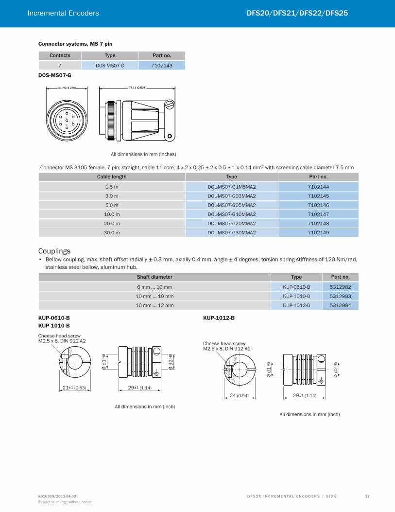
Connector systems, MS 7 pin
contacts type Part no.
7 DOS-MS07-G 7102143
DOS-MS07-G
Connector MS 3105 female, 7 pin, straight, cable 11 core, 4 x 2 x 0.25 + 2 x 0.5 + 1 x 0.14 mm2 with screening cable diameter 7.5 mm
cable length type Part no.
1.5 m DOL-MS07-G1M5MA2 7102144
3.0 m DOL-MS07-G03MMA2 7102145
5.0 m DOL-MS07-G05MMA2 7102146
10.0 m DOL-MS07-G10MMA2 7102147
20.0 m DOL-MS07-G20MMA2 7102148
30.0 m DOL-MS07-G30MMA2 7102149
Couplings • Bellow coupling, max. shaft offset radially ± 0.3 mm, axially 0.4 mm, angle ± 4 degrees, torsion spring stiffness of 120 Nm/rad,
stainless steel bellow, aluminum hub.
Shaft diameter type Part no.
6 mm … 10 mm KUP-0610-B 5312982
10 mm … 10 mm KUP-1010-B 5312983
10 mm … 12 mm KUP-1012-B 5312984
KUP-0610-B
KUP-1010-B
Cheese-head screwM2.5 x 8, DIN 912 A2
21±1 (0.83) 29±1 (1.14)
Ø d
1 H
8
Ø d
2 H
8
All dimensions in mm (inch)
KUP-1012-B
Cheese-head screwM2.5 x 8, DIN 912 A2
24 (0.94) 29±1 (1.14)
Ø d
1 H
8
Ø d
2 H
8
All dimensions in mm (inch)
All dimensions in mm (inches)
18
dfS20/dfS21/dfS22/dfS25 Incremental Encoders
Subject to change without notice8016309/2013.04.02d f S 2 X i n c r E m E n ta L E n c o d E r S | S i c K
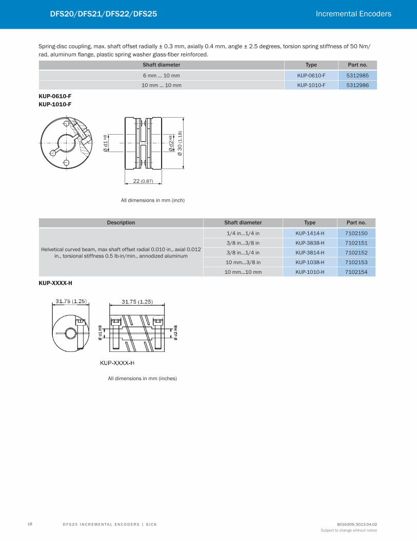
Spring-disc coupling, max. shaft offset radially ± 0.3 mm, axially 0.4 mm, angle ± 2.5 degrees, torsion spring stiffness of 50 Nm/rad, aluminum lange, plastic spring washer glass-iber reinforced.
Shaft diameter type Part no.
6 mm … 10 mm KUP-0610-F 5312985
10 mm … 10 mm KUP-1010-F 5312986
KUP-0610-F
KUP-1010-F
Ø d
2 H
8
Ø d
1 H
8
22 (0.87)Ø
30
(1
.18
)
All dimensions in mm (inch)
description Shaft diameter type Part no.
Helvetical curved beam, max shaft offset radial 0.010 in., axial 0.012 in., torsional stiffness 0.5 lb-in/min., annodized aluminum
1/4 in...1/4 in KUP-1414-H 7102150
3/8 in...3/8 in KUP-3838-H 7102151
3/8 in...1/4 in KUP-3814-H 7102152
10 mm...3/8 in KUP-1038-H 7102153
10 mm...10 mm KUP-1010-H 7102154
KUP-XXXX-H
All dimensions in mm (inches)
19
dfS20/dfS21/dfS22/dfS25Incremental Encoders
d f S 2 X i n c r E m E n ta L E n c o d E r S | S i c K8016309/2013.04.02
Subject to change without notice
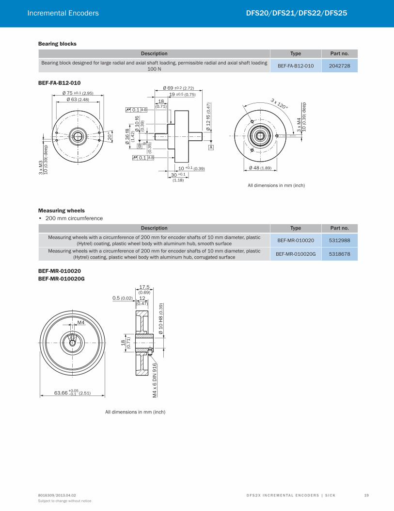
Bearing blocks
description type Part no.
Bearing block designed for large radial and axial shaft loading, permissible radial and axial shaft loading 100 N BEF-FA-B12-010 2042728
BEF-FA-B12-010
10 +0.1 (0.39)
30 +0.1
(1.18)
A
3 x 120°
Ø 75 ±0.1 (2.95)
Ø 63 (2.48)
20
°
3 x
M3
10
(0
.39
) d
ee
p
0.1 A-B
Ø 69 ±0.2 (2.72)
19 ±0.5 (0.75)
18(0.71)
B
0.1 A-B
Ø 3
6 f
8(1
.42
) Ø 1
0 f
6(0
.39
)9
(0.3
5)
Ø 1
2 f
6 (
0.4
7)
3 x
M4
10
(0
.39
) d
ee
p
Ø 48 (1.89)
All dimensions in mm (inch)
Measuring wheels
• 200 mm circumference
description type Part no.
Measuring wheels with a circumference of 200 mm for encoder shafts of 10 mm diameter, plastic (Hytrel) coating, plastic wheel body with aluminum hub, smooth surface BEF-MR-010020 5312988
Measuring wheels with a circumference of 200 mm for encoder shafts of 10 mm diameter, plastic (Hytrel) coating, plastic wheel body with aluminum hub, corrugated surface BEF-MR-010020G 5318678
BEF-MR-010020
BEF-MR-010020G
M4
All dimensions in mm (inch)
63.66+0.05–0.1 (2.51)
17.5(0.69)
12(0.47)
0.5 (0.02)
18
(0.7
1)
Ø 1
0 H
8 (
0.3
9)
M4
x 6
DIN
91
6

20
dfS20/dfS21/dfS22/dfS25 Incremental Encoders
Subject to change without notice8016309/2013.04.02d f S 2 X i n c r E m E n ta L E n c o d E r S | S i c K
• 500 mm circumference
description type Part no.
Measuring wheels with a circumference of 500 mm for encoder shafts of 10 mm diameter, plastic (Hytrel) coating, plastic wheel body with aluminum hub, smooth surface BEF-MR-010050 5312989
BEF-MR-010050
M5
159.16 (6.27)
All dimensions in mm (inch)
33(1.30)
24.5±0.2 (0.96)
0.6 (0.02)
Ø 1
0 H
8 (
0.3
9)
M5
x 6
DIN
91
6
20
(0.7
9)
• 200 mm circumference
description type Part no.
200 mm circumference measuring wheels for encoder shafts with a diameter of 10 mm, O-ring NBR70 surface BEF-MR010020R 2055224
BEF-MR010020R
Ø 6
3.6
6 (
2.5
1)
Ø X
H7
M5
17 (0.67)
8 (0.31)
4 (0.16)
All dimensions in mm (inch)
21
dfS20/dfS21/dfS22/dfS25Incremental Encoders
d f S 2 X i n c r E m E n ta L E n c o d E r S | S i c K8016309/2013.04.02
Subject to change without notice
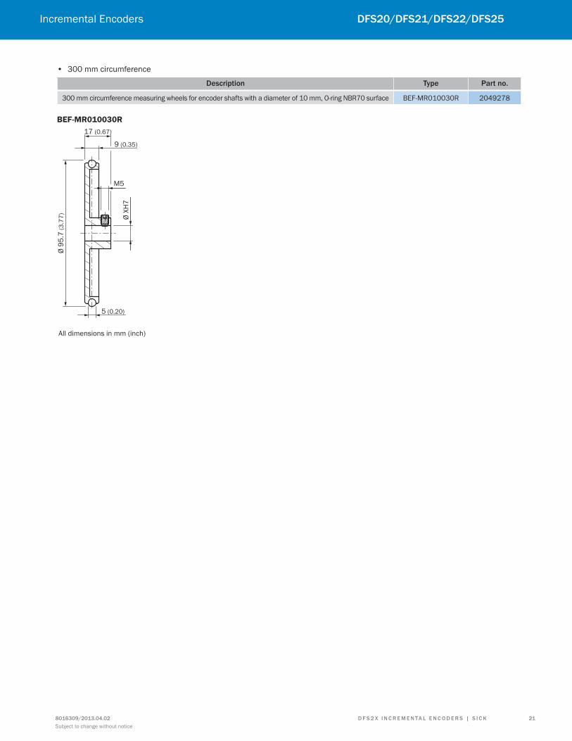
• 300 mm circumference
description type Part no.
300 mm circumference measuring wheels for encoder shafts with a diameter of 10 mm, O-ring NBR70 surface BEF-MR010030R 2049278
BEF-MR010030R
Ø 9
5.7
(3
.77
)
All dimensions in mm (inch)
Ø X
H7
M5
17 (0.67)
9 (0.35)
5 (0.20)

22
dfS20/dfS21/dfS22/dfS25 Incremental Encoders
Subject to change without notice8016309/2013.04.02d f S 2 X i n c r E m E n ta L E n c o d E r S | S i c K
• 500 mm circumference
description type Part no.
500 mm circumference measuring wheels for encoder shafts with a diameter of 6 mm, O-ring NBR70 surface BEF-MR006050R 2055225
500 mm circumference measuring wheels for encoder shafts with a diameter of 10 mm, O-ring NBR70 surface BEF-MR010050R 2055227
BEF-MR006050R
BEF-MR010050R
Ø 1
59
.2 (
6.2
7)
All dimensions in mm (inch)
Ø X
H7
M5
5 (0.20)
9 (0.35)
17 (0.67)

23
dfS20/dfS21/dfS22/dfS25Incremental Encoders
Notes
d f S 2 X i n c r E m E n ta L E n c o d E r S | S i c K8016309/2013.04.02
Subject to change without notice

8016
309/
2013
.04.
02 ∙
Sub
ject
to c
hang
e w
ithou
t not
ice
SICK, Inc. | Minneapolis, MN | Unites States | www.sickusa.com
Leading technologies
With a staff of more than 5,000 and over 50 subsidiaries and representa-
tions worldwide, SICK is one of the leading and most successful manufac-
turers of sensor technology. The power of innovation and solution competency have made SICK the global market leader. No matter what the project and industry may be, talking with an expert from SICK will provide you with an ideal basis for your plans – there is no need to settle for anything less than the best.
Unique product range
• Non-contact detecting, counting, classifying, positioning and measur-ing of any type of object or media
• Accident and operator protection with sensors, safety software and services
• Automatic identiication with bar code and RFID readers
• Laser measurement technology for detecting the volume, position and contour of people and objects
• Complete system solutions for analy-
sis and low measurement of gases and liquids
Comprehensive services
• SICK LifeTime Services – for safety and productivity
• Application centers in Europe, Asia and North America for the develop-
ment of system solutions under real-world conditions
• E-Business Partner Portal www.mysick.com – price and availabi-lity of products, requests for quotation
and online orders
SicK at a glance
Worldwide presence with
subsidiaries in the following
countries:
australia Belgium/Luxembourg Brasil ceská republika canada china danmark deutschland España france Great Britain india israel italia Japan
méxico nederland norge Österreich Polska românia russia Schweiz Singapore Slovenija South africa South Korea Suomi Sverige taiwan türkiye united arab Emirates uSa
Please ind detailed addresses and additional representatives and agencies in all major industrial nations at www.sick.com