Dewa Latest Reg 2014
819
Transcript of Dewa Latest Reg 2014

8/15/2019 Dewa Latest Reg 2014
http://slidepdf.com/reader/full/dewa-latest-reg-2014 1/817

8/15/2019 Dewa Latest Reg 2014
http://slidepdf.com/reader/full/dewa-latest-reg-2014 2/817

8/15/2019 Dewa Latest Reg 2014
http://slidepdf.com/reader/full/dewa-latest-reg-2014 3/817
“The UAE is striving to develop and boost its rich resources and expertise in the
international energy markets and enhance its leading role as a world centre for
renewable energy research and development.”

8/15/2019 Dewa Latest Reg 2014
http://slidepdf.com/reader/full/dewa-latest-reg-2014 4/817

8/15/2019 Dewa Latest Reg 2014
http://slidepdf.com/reader/full/dewa-latest-reg-2014 5/817

8/15/2019 Dewa Latest Reg 2014
http://slidepdf.com/reader/full/dewa-latest-reg-2014 6/817

8/15/2019 Dewa Latest Reg 2014
http://slidepdf.com/reader/full/dewa-latest-reg-2014 7/817
“DEWA’s projects are the life, essence and backbone of Dubai’s infrastructure.
DEWA provides world-class services at the highest levels of reliability, quality and
best international practices and technologies, to ensure uninterrupted supply
of electricity and water services and achieve the sustainable development
of the UAE.”

8/15/2019 Dewa Latest Reg 2014
http://slidepdf.com/reader/full/dewa-latest-reg-2014 8/817

8/15/2019 Dewa Latest Reg 2014
http://slidepdf.com/reader/full/dewa-latest-reg-2014 9/817
Dubai has emerged as a leading regional business
hub and the favourite place for investment in theMiddle East because of its robust and vigorous
infrastructure base.
In line with HH Sheikh Mohammed Bin Rashid Al
Maktoum, Vice President and Prime Minister of the UAE
and Ruler of Dubai, to firmly positioning Dubai city as
a global hub for finance, business and tourism, and to
promote prudent use of power and water.
Dubai Electricity and Water Authority (DEWA) exert
strenuous efforts on promoting the best practicesand operational excellence across all aspects, through
DEWA Vision to become a sustainable world-class utility
and to support the sustainable development of Dubai.
This Infrastructure NOC Technical Manual has been
developed specifically to support DEWA customers for
swift obtaining of the infrastructure NOC submitted
to the Infrastructure Information and Permits
department (II&P).
It clearly demonstrates the highest standards ofexcellence, safety, and reliability in the various
activities undertaken by DEWA stakeholders/
customers on projects in DEWA’s reservation or Right OfWay (ROW).
This manual deemed the technical reference to
support DEWA achieving the planned goals by sharing
the best construction practices with all stakeholders,
consultants, contractors, and private developers.
Pursuant to HH Sheikh Mohammed bin Rashid
Al Maktoum directions to support the Smart City
initiative, DEWA will launch the infrastructure NOC
Technical Manual as a digital web-based version thatcan be accessed and downloaded anytime, anywhere
cost-free.
Following the guidelines specified in the infrastructure
NOC technical manual will integrate the efforts to
accomplish Dubai vision.
Best regards,
HE Saeed Mohammed Al Tayer
MD and CEODubai Electricity and Water Authority
Message from the MD & CEO of DEWA

8/15/2019 Dewa Latest Reg 2014
http://slidepdf.com/reader/full/dewa-latest-reg-2014 10/817

8/15/2019 Dewa Latest Reg 2014
http://slidepdf.com/reader/full/dewa-latest-reg-2014 11/817

8/15/2019 Dewa Latest Reg 2014
http://slidepdf.com/reader/full/dewa-latest-reg-2014 12/817
iv Infrastructure NOC Technical Manual [Electricity]World class customer services
In line with DEWA’s vision, “A sustainable world-classutility,” and its strategic goal to drive the vision,which is to “Deliver reliable and quality services,” theInfrastructure NOC Technical Manual objectives werecarefully envisioned as follows:
To provide a reference to DEWA Customers for DEWA’sTechnical Requirements.
To reduce the duration for issuing theNOC applications.
To release the NOC application from first submission
To meet the customer satisfactions.
Consolidated, easy-to-use andreader-friendly
The Infrastructure NOC Technical Manual furnishes theTechnical requirements for the projects working withinthe ROW/DEWA corridors in the Emirate of Dubai.
The design and development of the Infrastructure NOCTechnical Manual was adequately benchmarked for
making it reader-friendly and easy to refer. Upon thisfactor the technical contents are segmented into fourclassified chapters as noted below, each addressing aseparate theme with a unique colour code and special-attention markings for quicker reference, and recall.
Chapter - 1 (Red) - Utilities
Chapter - 2 (Grey) - Road works
Chapter - 3 (Blue) - Structures
Chapter - 4 (Green) - General projects
In addition, the manual’s content featuring 50Nos. of NOC types is supported by explanatorynotes, corresponding CAD drawings, 3D drawings,illustrations, tables and site photographs.
The infrastructure NOC Technical Manual consideredthe following:
NOC applicants should follow the indicatedclearances and protection details; whereas theindicated dimensions are the minimum dimensions
unless and otherwise mentioned.
In case the NOC applicant is not able to conform theInfrastructure NOC Technical Manual requirements,
hence the closest similar case to be followed inaccordance with the site conditions. In such instancesapplication will be studied on a case-to-case basistogether with the concerned department(s).
Any NOC type not included in the Manual willbe studied according to the site conditions;subsequently appropriate action will thereofbe taken.
Special sections for Abbreviations, Definitions andReferences have also been included.
The Infrastructure NOC Technical Manual impliedthe standard case of the service/utility installationand deemed it was laid/installed in the center ofits corridor.
Valve chambers and manholes will be considered inaccordance to the site conditions
No one is holding the right(s) to deprive any partyto lay/install their services/utilities within theirdedicated corridor.
The stipulated technical details within theInfrastructure NOC Technical Manual werecollaboratively obtained and approved from DEWA’srelevant departments.
Infrastructure Information &Permits [II&P] Department – Activitiesat a glance
The department’s core activity is: Issuing designand construction No Objection Certificate (NOC) forInfrastructure Projects (Roads/Network Services),
General Projects & House Connections work tocustomers (Authorities/Consultants/Contractors &Developers) in order to work within the Right Of Way(R.O.W) limit or within DEWA Reservation/ DEWAPower Station.
The main objectives of issuing NOC are
Saving DEWA Corridors (Electricity/Water) ForFuture Plans.
Protect DEWA Existing Services from potentialdamages.
Support ongoing DEWA Projects.
Ensuring the security of DEWA assets

8/15/2019 Dewa Latest Reg 2014
http://slidepdf.com/reader/full/dewa-latest-reg-2014 13/817
xvAreas of activities of Infrastructure Information &
Permits department are:
Provide a single window for Infrastructure Projects &General /House Connections NOCs within ROW.
Provide support services for approving the shopdrawing, cable diversion and ducts for ElectricityNOCs only.
Issuing services information and trial pits NOC forElectricity and Water.
Estimate for HV Cables diversion under Road &
Infrastructure projects.
BOQ approval for DEWA-Electricity future ductsinstallation under RTA Road Projects.
Issuance of Project Completion Certificate & As-Built approval for Road & Infrastructure Projects.
Updating DEWA land base in GIS.
Information, excellence and innovation are imperative for sustainability
Dubai Electricity and Water Authority is a thought-leadership and strategy-focussed organisation, aspiringto be the best in the business and is professionally socommitted to that goal. The Authority has acknowledged
the notion that for corporate excellence to sustain,improvement on excellence and innovation is a continuousendeavour. In HH Sheikh Mohammed’s wise words, “in therace for excellence, there is no finish line.”

8/15/2019 Dewa Latest Reg 2014
http://slidepdf.com/reader/full/dewa-latest-reg-2014 14/817

8/15/2019 Dewa Latest Reg 2014
http://slidepdf.com/reader/full/dewa-latest-reg-2014 15/817
xvii
Chapter 1 - Utilities1. Laying of Proposed Utilities - Electricity Low Voltage (LV) Cables ............................... 1
2. Laying of Proposed Utilities - Electricity High Voltage (HV) cables ............................ 19
3. Installation of Proposed OHL - Electricity HV (6.6/11/33 kV) .....................................38
4. Laying of Proposed Utilities - Electricity 132 kV Trough ............................................. 51
5. Laying of Proposed Utilities - Electricity 132 kV Duct Bank ....................................... 73
6. Laying of Proposed Utilities - Electricity 132 kV Joint Bay/Transition Joint .................... 90
7. Installation of Proposed OHL - Electricity EHV (132/400 kV) ................................... 1078. Laying of Proposed Utilities - Water Distribution Pipelines ...................................... 121
9. Laying of Proposed Utilities - Water Transmission Pipelines ................................... 139
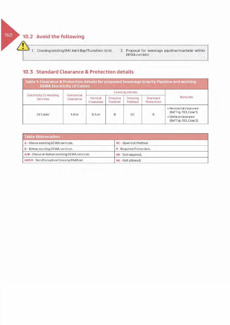
10. Laying of Proposed Utilities - Sewerage Gravity Pipelines ....................................... 159
11. Laying of Proposed Utilities - Sewerage Pressure Pipelines ......................................175
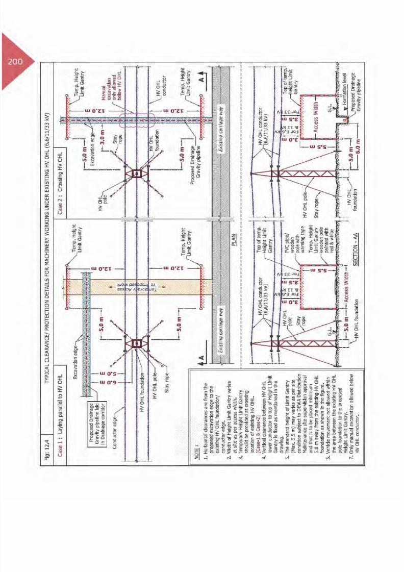
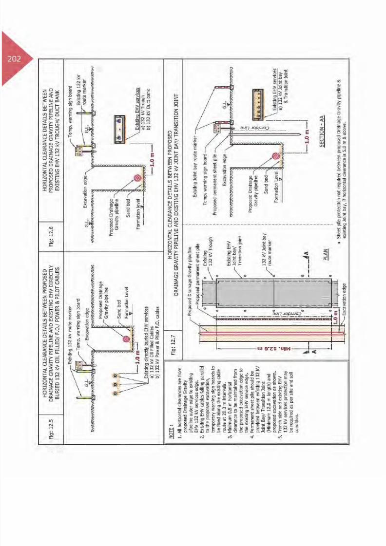
12. Laying of Proposed Utilities - Drainage Gravity Pipelines ........................................ 194
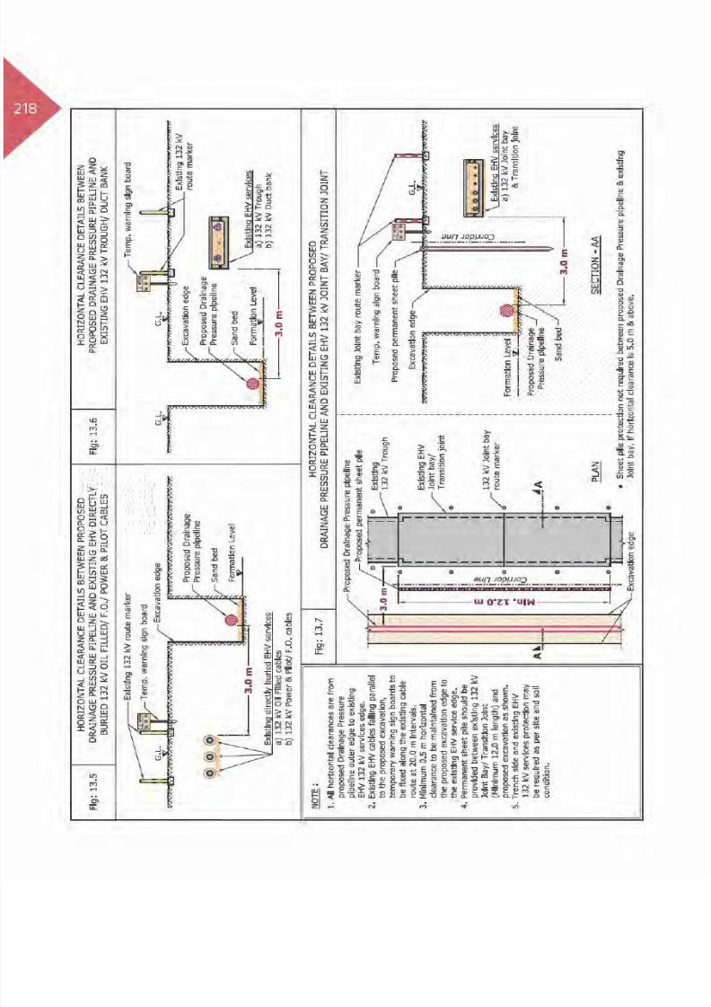
13. Laying of Proposed Utilities - Drainage Pressure Pipelines ...................................... 210
14. Laying of Proposed Utilities - Irrigation Distribution Pipelines................................ 229
15. Laying of Proposed Utilities - Irrigation Main Pipelines .......................................... 247
16. Laying of Proposed Utilities - District Cooling Pipelines .........................................266
17. Laying of Proposed Utilities - Gas/Fuel Pipelines.................................................... 282
18. Laying of Proposed Utilities - Telecommunication ................................................299
Chapter 2 - Road Works
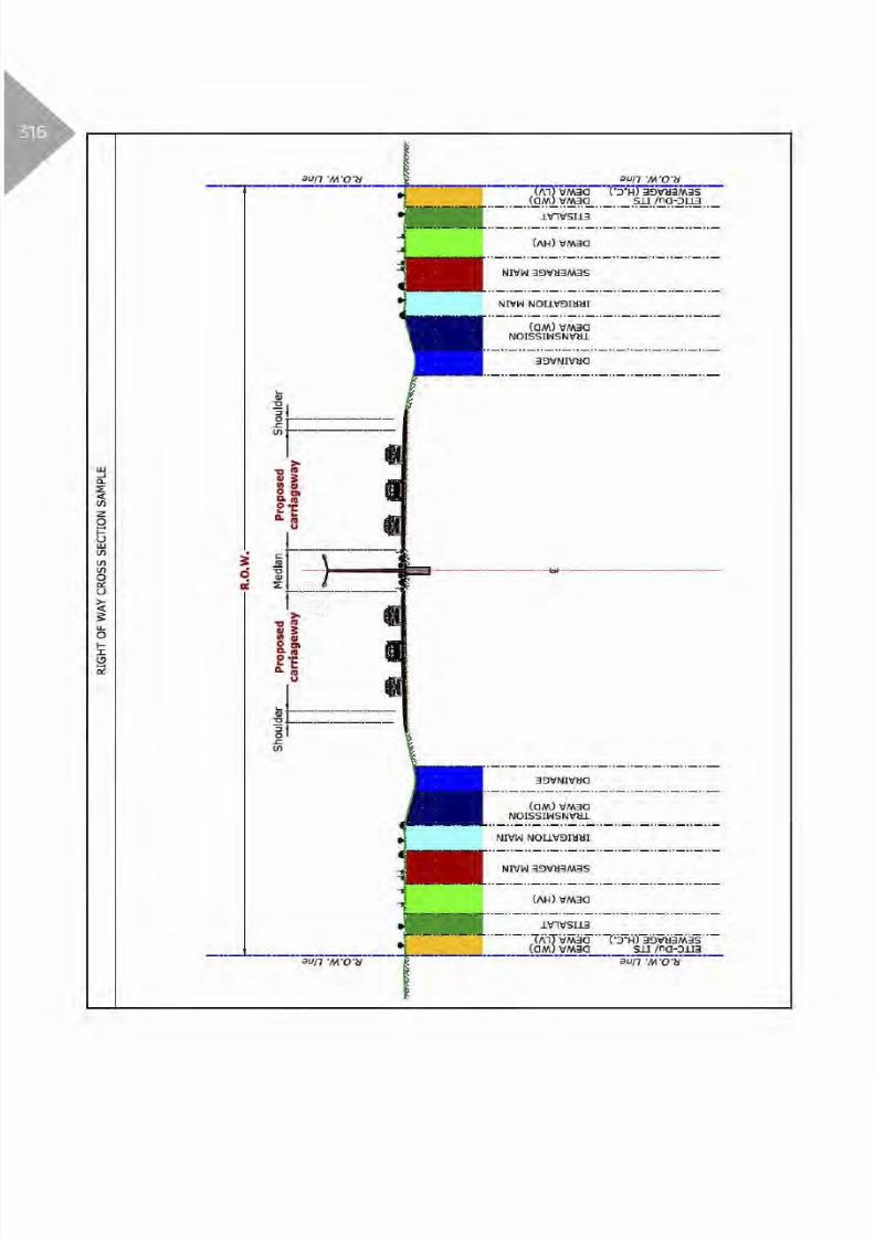
19. Proposed Road Work - Asphalt Carriageway ...........................................................315
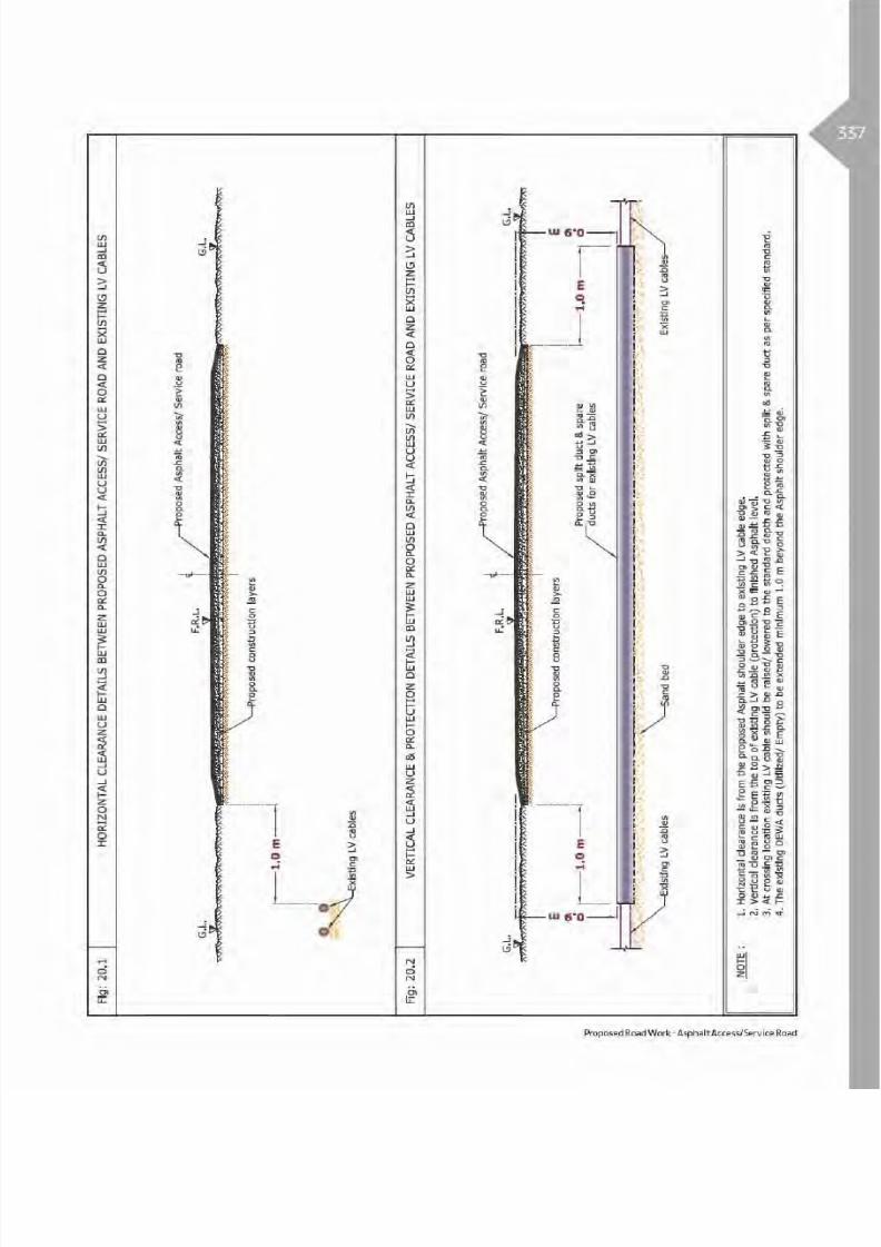
20. Proposed Road Work - Asphalt Access/Service Road .............................................. 33421. Proposed Road Work - Asphalt Parking ................................................................. 352
22. Proposed Road Work - Interlock Carriageway ........................................................ 370
23. Proposed Road Work - Interlock Access/Service Road ............................................389
24. Proposed Road Work - Interlock Parking ..............................................................407
25. Proposed Road Work - Bridges/Interchanges/Railway/Ramps/Flyover/Roundabout ...425
26. Proposed Grading ................................................................................................443
Contents

8/15/2019 Dewa Latest Reg 2014
http://slidepdf.com/reader/full/dewa-latest-reg-2014 16/817

8/15/2019 Dewa Latest Reg 2014
http://slidepdf.com/reader/full/dewa-latest-reg-2014 17/817
CHAPTER 1
UTILITIES

8/15/2019 Dewa Latest Reg 2014
http://slidepdf.com/reader/full/dewa-latest-reg-2014 18/817

8/15/2019 Dewa Latest Reg 2014
http://slidepdf.com/reader/full/dewa-latest-reg-2014 19/817

8/15/2019 Dewa Latest Reg 2014
http://slidepdf.com/reader/full/dewa-latest-reg-2014 20/817

8/15/2019 Dewa Latest Reg 2014
http://slidepdf.com/reader/full/dewa-latest-reg-2014 21/817
8/15/2019 Dewa Latest Reg 2014
http://slidepdf.com/reader/full/dewa-latest-reg-2014 22/817

8/15/2019 Dewa Latest Reg 2014
http://slidepdf.com/reader/full/dewa-latest-reg-2014 23/817
5Table 2: Clearance & Protection details for proposed laying of LV cable and existing DEWA
Electricity HV services
Electricity HV existing
Services
Horizontal
Clearance
Crossing DetailsRemarksVertical
Clearance
Crossing
Position
Crossing
Method
Standard
Protection
HV
(6.6/11/33 kV) Power/
Pilot Cable and Joints 1.0 m
0.15 m A/B OC R
(Ref Fig: 1.2, Case1)
(Ref Fig: 1.3)
(Ref Fig: 1.2, Case2)
HV
(6.6/11/33 kV) ManholeNA - - R
(Ref Fig: 1.2, Case1)
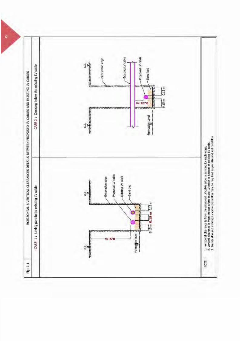
HV(6.6/11/33 kV) O.H.L
2.0 m NR - - R (Ref Fig: 1.4)
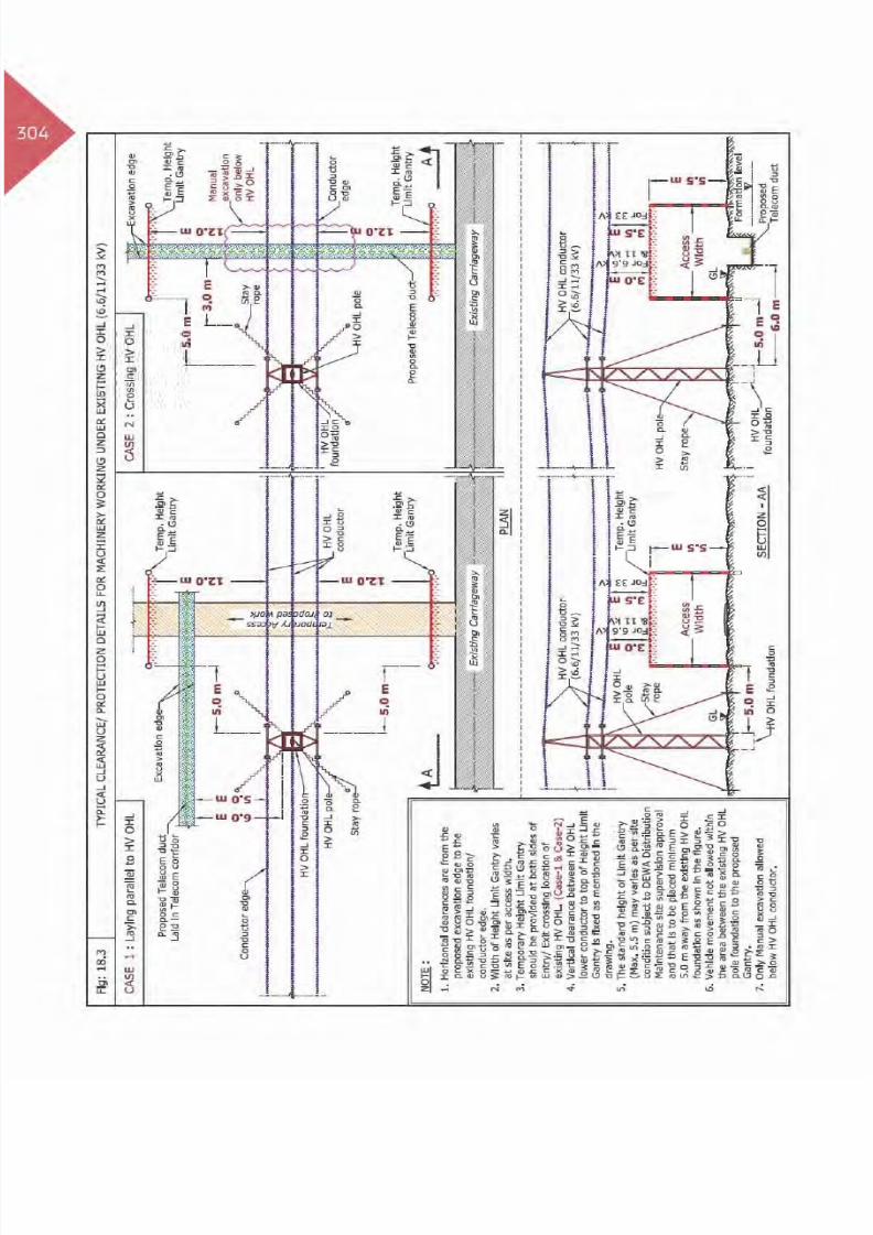
Clearance & Protection details for access working under Existing HV OHL
HV
(6.6/11 kV) O.H.L.
5.0 m
3.0 m
B - R
(Ref Fig: 1.5)
(Ref Fig: 1.5)
(Ref Fig: 1.5)
HV
(33 kV) O.H.L.3.5 m
Table Abbreviation
A - Above existing DEWA services. OC - Open Cut Method.
B - Below existing DEWA services. R - Required Protection.
A/B - Above or Below existing DEWA services. NR - Not required.
NDCM - Non Disruptive Crossing Method. NA - Not allowed.
Laying of Proposed Utilities - Electricity Low Voltage (LV) Cables

8/15/2019 Dewa Latest Reg 2014
http://slidepdf.com/reader/full/dewa-latest-reg-2014 24/817

8/15/2019 Dewa Latest Reg 2014
http://slidepdf.com/reader/full/dewa-latest-reg-2014 25/817

8/15/2019 Dewa Latest Reg 2014
http://slidepdf.com/reader/full/dewa-latest-reg-2014 26/817

8/15/2019 Dewa Latest Reg 2014
http://slidepdf.com/reader/full/dewa-latest-reg-2014 27/817

8/15/2019 Dewa Latest Reg 2014
http://slidepdf.com/reader/full/dewa-latest-reg-2014 28/817

8/15/2019 Dewa Latest Reg 2014
http://slidepdf.com/reader/full/dewa-latest-reg-2014 29/817

8/15/2019 Dewa Latest Reg 2014
http://slidepdf.com/reader/full/dewa-latest-reg-2014 30/817

8/15/2019 Dewa Latest Reg 2014
http://slidepdf.com/reader/full/dewa-latest-reg-2014 31/817

8/15/2019 Dewa Latest Reg 2014
http://slidepdf.com/reader/full/dewa-latest-reg-2014 32/817

8/15/2019 Dewa Latest Reg 2014
http://slidepdf.com/reader/full/dewa-latest-reg-2014 33/817

8/15/2019 Dewa Latest Reg 2014
http://slidepdf.com/reader/full/dewa-latest-reg-2014 34/817

8/15/2019 Dewa Latest Reg 2014
http://slidepdf.com/reader/full/dewa-latest-reg-2014 35/817

8/15/2019 Dewa Latest Reg 2014
http://slidepdf.com/reader/full/dewa-latest-reg-2014 36/817

8/15/2019 Dewa Latest Reg 2014
http://slidepdf.com/reader/full/dewa-latest-reg-2014 37/817

8/15/2019 Dewa Latest Reg 2014
http://slidepdf.com/reader/full/dewa-latest-reg-2014 38/817

8/15/2019 Dewa Latest Reg 2014
http://slidepdf.com/reader/full/dewa-latest-reg-2014 39/817

8/15/2019 Dewa Latest Reg 2014
http://slidepdf.com/reader/full/dewa-latest-reg-2014 40/817

8/15/2019 Dewa Latest Reg 2014
http://slidepdf.com/reader/full/dewa-latest-reg-2014 41/817

8/15/2019 Dewa Latest Reg 2014
http://slidepdf.com/reader/full/dewa-latest-reg-2014 42/817

8/15/2019 Dewa Latest Reg 2014
http://slidepdf.com/reader/full/dewa-latest-reg-2014 43/817

8/15/2019 Dewa Latest Reg 2014
http://slidepdf.com/reader/full/dewa-latest-reg-2014 44/817

8/15/2019 Dewa Latest Reg 2014
http://slidepdf.com/reader/full/dewa-latest-reg-2014 45/817

8/15/2019 Dewa Latest Reg 2014
http://slidepdf.com/reader/full/dewa-latest-reg-2014 46/817

8/15/2019 Dewa Latest Reg 2014
http://slidepdf.com/reader/full/dewa-latest-reg-2014 47/817

8/15/2019 Dewa Latest Reg 2014
http://slidepdf.com/reader/full/dewa-latest-reg-2014 48/817

8/15/2019 Dewa Latest Reg 2014
http://slidepdf.com/reader/full/dewa-latest-reg-2014 49/817

8/15/2019 Dewa Latest Reg 2014
http://slidepdf.com/reader/full/dewa-latest-reg-2014 50/817

8/15/2019 Dewa Latest Reg 2014
http://slidepdf.com/reader/full/dewa-latest-reg-2014 51/817

8/15/2019 Dewa Latest Reg 2014
http://slidepdf.com/reader/full/dewa-latest-reg-2014 52/817

8/15/2019 Dewa Latest Reg 2014
http://slidepdf.com/reader/full/dewa-latest-reg-2014 53/817

8/15/2019 Dewa Latest Reg 2014
http://slidepdf.com/reader/full/dewa-latest-reg-2014 54/817

8/15/2019 Dewa Latest Reg 2014
http://slidepdf.com/reader/full/dewa-latest-reg-2014 55/817

8/15/2019 Dewa Latest Reg 2014
http://slidepdf.com/reader/full/dewa-latest-reg-2014 56/817

8/15/2019 Dewa Latest Reg 2014
http://slidepdf.com/reader/full/dewa-latest-reg-2014 57/817
8/15/2019 Dewa Latest Reg 2014
http://slidepdf.com/reader/full/dewa-latest-reg-2014 58/817

8/15/2019 Dewa Latest Reg 2014
http://slidepdf.com/reader/full/dewa-latest-reg-2014 59/817

8/15/2019 Dewa Latest Reg 2014
http://slidepdf.com/reader/full/dewa-latest-reg-2014 60/817

8/15/2019 Dewa Latest Reg 2014
http://slidepdf.com/reader/full/dewa-latest-reg-2014 61/817

8/15/2019 Dewa Latest Reg 2014
http://slidepdf.com/reader/full/dewa-latest-reg-2014 62/817
8/15/2019 Dewa Latest Reg 2014
http://slidepdf.com/reader/full/dewa-latest-reg-2014 63/817
8/15/2019 Dewa Latest Reg 2014
http://slidepdf.com/reader/full/dewa-latest-reg-2014 64/817

8/15/2019 Dewa Latest Reg 2014
http://slidepdf.com/reader/full/dewa-latest-reg-2014 65/817

8/15/2019 Dewa Latest Reg 2014
http://slidepdf.com/reader/full/dewa-latest-reg-2014 66/817
8/15/2019 Dewa Latest Reg 2014
http://slidepdf.com/reader/full/dewa-latest-reg-2014 67/817
8/15/2019 Dewa Latest Reg 2014
http://slidepdf.com/reader/full/dewa-latest-reg-2014 68/817

8/15/2019 Dewa Latest Reg 2014
http://slidepdf.com/reader/full/dewa-latest-reg-2014 69/817
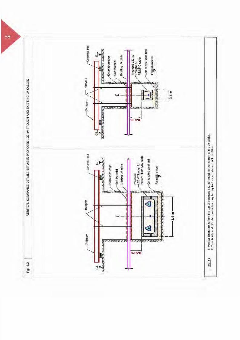
51
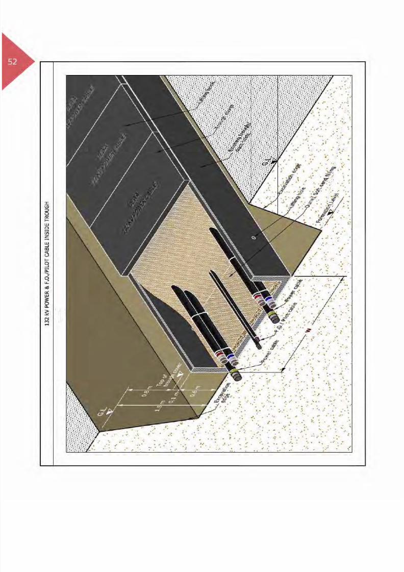
4. Laying of Proposed Utilities –Electricity 132 kV Trough
4.1 Introduction
EHV cables have unique properties of transmittingpower from generation power plant to substations.
Directly buried cables are at high risk of damagesdue to different site activities. EHV cables aredesigned to emit no electric and magnetic fieldsto minimise power losses, and for the purposeof supporting sustainability of power supply
132 kV cables which are laid inside concrete troughcovered with concrete slab. The concrete troughsand slabs are designed to withstand certain loadsand protect the power cables from damages.132 kV Trough is laid within Right Of Way. Therefore,during construction activities DEWA existing assetsto be protected as per specified standard.
Laying of Proposed Utilities – Electricity 132 kV Trough
8/15/2019 Dewa Latest Reg 2014
http://slidepdf.com/reader/full/dewa-latest-reg-2014 70/817

8/15/2019 Dewa Latest Reg 2014
http://slidepdf.com/reader/full/dewa-latest-reg-2014 71/817
53
Photo: 132 kV Trough Laying
Photo: 132 kV Cable laying inside Trough
Laying of Proposed Utilities – Electricity 132 kV Trough

8/15/2019 Dewa Latest Reg 2014
http://slidepdf.com/reader/full/dewa-latest-reg-2014 72/817

8/15/2019 Dewa Latest Reg 2014
http://slidepdf.com/reader/full/dewa-latest-reg-2014 73/817

8/15/2019 Dewa Latest Reg 2014
http://slidepdf.com/reader/full/dewa-latest-reg-2014 74/817

8/15/2019 Dewa Latest Reg 2014
http://slidepdf.com/reader/full/dewa-latest-reg-2014 75/817
8/15/2019 Dewa Latest Reg 2014
http://slidepdf.com/reader/full/dewa-latest-reg-2014 76/817

8/15/2019 Dewa Latest Reg 2014
http://slidepdf.com/reader/full/dewa-latest-reg-2014 77/817

8/15/2019 Dewa Latest Reg 2014
http://slidepdf.com/reader/full/dewa-latest-reg-2014 78/817

8/15/2019 Dewa Latest Reg 2014
http://slidepdf.com/reader/full/dewa-latest-reg-2014 79/817

8/15/2019 Dewa Latest Reg 2014
http://slidepdf.com/reader/full/dewa-latest-reg-2014 80/817

8/15/2019 Dewa Latest Reg 2014
http://slidepdf.com/reader/full/dewa-latest-reg-2014 81/817
8/15/2019 Dewa Latest Reg 2014
http://slidepdf.com/reader/full/dewa-latest-reg-2014 82/817

8/15/2019 Dewa Latest Reg 2014
http://slidepdf.com/reader/full/dewa-latest-reg-2014 83/817

8/15/2019 Dewa Latest Reg 2014
http://slidepdf.com/reader/full/dewa-latest-reg-2014 84/817

8/15/2019 Dewa Latest Reg 2014
http://slidepdf.com/reader/full/dewa-latest-reg-2014 85/817

8/15/2019 Dewa Latest Reg 2014
http://slidepdf.com/reader/full/dewa-latest-reg-2014 86/817

8/15/2019 Dewa Latest Reg 2014
http://slidepdf.com/reader/full/dewa-latest-reg-2014 87/817

8/15/2019 Dewa Latest Reg 2014
http://slidepdf.com/reader/full/dewa-latest-reg-2014 88/817

8/15/2019 Dewa Latest Reg 2014
http://slidepdf.com/reader/full/dewa-latest-reg-2014 89/817

8/15/2019 Dewa Latest Reg 2014
http://slidepdf.com/reader/full/dewa-latest-reg-2014 90/817

8/15/2019 Dewa Latest Reg 2014
http://slidepdf.com/reader/full/dewa-latest-reg-2014 91/817

8/15/2019 Dewa Latest Reg 2014
http://slidepdf.com/reader/full/dewa-latest-reg-2014 92/817

8/15/2019 Dewa Latest Reg 2014
http://slidepdf.com/reader/full/dewa-latest-reg-2014 93/817
75
1 3 2
k V D u c
t B a n
k w
o r k
a t s i t e
Laying of Proposed Utilities - Electricity 132 kV Duct Bank

8/15/2019 Dewa Latest Reg 2014
http://slidepdf.com/reader/full/dewa-latest-reg-2014 94/817

8/15/2019 Dewa Latest Reg 2014
http://slidepdf.com/reader/full/dewa-latest-reg-2014 95/817

8/15/2019 Dewa Latest Reg 2014
http://slidepdf.com/reader/full/dewa-latest-reg-2014 96/817

8/15/2019 Dewa Latest Reg 2014
http://slidepdf.com/reader/full/dewa-latest-reg-2014 97/817
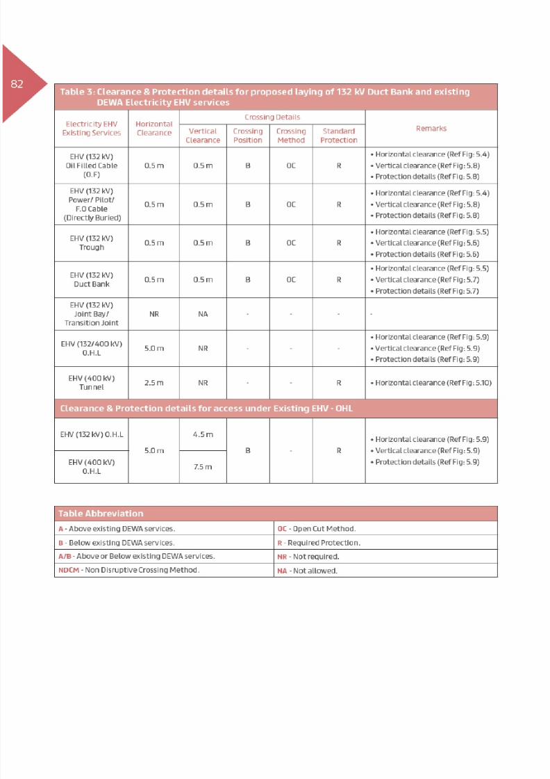
79Table 2: Clearance & Protection details for proposed laying of 132 kV Duct Bank and exisiting
DEWA Electricity HV services
Electricity HV Existing
Services
Horizontal
Clearance
Crossing DetailsRemarksVertical
Clearance
Crossing
Position
Crossing
Method
Standard
Protection
HV
(6.6/11/33 kV) Power/
pilot Cables and Joints
0.15 m 0.15 m B OC R
(Ref Fig: 5.2, Case 1)
(Ref Fig: 5.3, Case 1)
(Ref Fig: 5.3, Case 1 & 2)
HV
(6.6/11/33 kV) Manhole0.15 m NA - - -
(Ref Fig: 5.2, Case 2)
HV(6.6/11/33 kV) O.H.L
- - - - - -
Clearance & Protection details for access under Existing HV-OHL
HV
(6.6/11 kV) O.H.L
-
-
- - - -HV
(33 kV) O.H.L-
Table AbbreviationA - Above existing DEWA services. OC - Open Cut Method.
B - Below existing DEWA services. R - Required Protection.
A/B - Above or Below existing DEWA services. NR - Not required.
NDCM - Non Disruptive Crossing Method. NA - Not allowed.
Laying of Proposed Utilities - Electricity 132 kV Duct Bank

8/15/2019 Dewa Latest Reg 2014
http://slidepdf.com/reader/full/dewa-latest-reg-2014 98/817

8/15/2019 Dewa Latest Reg 2014
http://slidepdf.com/reader/full/dewa-latest-reg-2014 99/817
8/15/2019 Dewa Latest Reg 2014
http://slidepdf.com/reader/full/dewa-latest-reg-2014 100/817

8/15/2019 Dewa Latest Reg 2014
http://slidepdf.com/reader/full/dewa-latest-reg-2014 101/817

8/15/2019 Dewa Latest Reg 2014
http://slidepdf.com/reader/full/dewa-latest-reg-2014 102/817

8/15/2019 Dewa Latest Reg 2014
http://slidepdf.com/reader/full/dewa-latest-reg-2014 103/817

8/15/2019 Dewa Latest Reg 2014
http://slidepdf.com/reader/full/dewa-latest-reg-2014 104/817

8/15/2019 Dewa Latest Reg 2014
http://slidepdf.com/reader/full/dewa-latest-reg-2014 105/817

8/15/2019 Dewa Latest Reg 2014
http://slidepdf.com/reader/full/dewa-latest-reg-2014 106/817

8/15/2019 Dewa Latest Reg 2014
http://slidepdf.com/reader/full/dewa-latest-reg-2014 107/817

8/15/2019 Dewa Latest Reg 2014
http://slidepdf.com/reader/full/dewa-latest-reg-2014 108/817

8/15/2019 Dewa Latest Reg 2014
http://slidepdf.com/reader/full/dewa-latest-reg-2014 109/817

8/15/2019 Dewa Latest Reg 2014
http://slidepdf.com/reader/full/dewa-latest-reg-2014 110/817

8/15/2019 Dewa Latest Reg 2014
http://slidepdf.com/reader/full/dewa-latest-reg-2014 111/817
93
132 kV Link box - Bonding Cable
132 kV Joint Bay with Markers and Link Box
Laying of Proposed Utilities - Electricity 132 kV Joint Bay/Transition Joint

8/15/2019 Dewa Latest Reg 2014
http://slidepdf.com/reader/full/dewa-latest-reg-2014 112/817

8/15/2019 Dewa Latest Reg 2014
http://slidepdf.com/reader/full/dewa-latest-reg-2014 113/817

8/15/2019 Dewa Latest Reg 2014
http://slidepdf.com/reader/full/dewa-latest-reg-2014 114/817

8/15/2019 Dewa Latest Reg 2014
http://slidepdf.com/reader/full/dewa-latest-reg-2014 115/817
97Table 2: Clearance & Protection details for proposed 132 kV cable Joint bay/Transition Joint and
existing DEWA Electricity HV services
Electricity HV existing
Services
Horizontal
Clearance
Crossing DetailsRemarksVertical
Clearance
Crossing
Position
Crossing
Method
Standard
Protection
HV
(6.6/11/33 kV) Power/
Pilot Cable and Joints
0.3 m NA - - R
(Ref Fig: 6.2, Case 1)
(Ref Fig: 6.2)
HV
(6.6/11/33 kV) Manhole0.3 m NA - - R
(Ref Fig: 6.2, Case 2)
HV
(6.6/11/33 kV) O.H.L.1.0 m NR - - R
(Ref Fig: 6.3)
Clearance & Protection details for access under Existing HV-OHL
HV
(6.6/11 kV) O.H.L
5.0 m
3.0 m
B - R
(Ref Fig: 6.4)
(Ref Fig: 6.4)
(Ref Fig: 6.4)
HV
(33 kV) O.H.L3.5 m
Table Abbreviation
A - Above existing DEWA services. OC - Open Cut Method.
B - Below existing DEWA services. R - Required Protection.
A/B - Above or Below existing DEWA services. NR - Not required.
NDCM - Non Disruptive Crossing Method. NA - Not allowed.
Laying of Proposed Utilities - Electricity 132 kV Joint Bay/Transition Joint
8/15/2019 Dewa Latest Reg 2014
http://slidepdf.com/reader/full/dewa-latest-reg-2014 116/817

8/15/2019 Dewa Latest Reg 2014
http://slidepdf.com/reader/full/dewa-latest-reg-2014 117/817

8/15/2019 Dewa Latest Reg 2014
http://slidepdf.com/reader/full/dewa-latest-reg-2014 118/817

8/15/2019 Dewa Latest Reg 2014
http://slidepdf.com/reader/full/dewa-latest-reg-2014 119/817
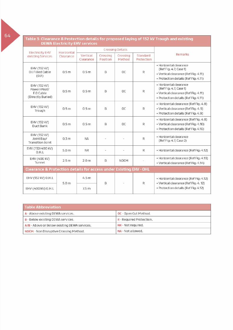
101Table 3: Clearance & Protection details for proposed 132 kV cable Joint bay/Transition Joint and
existing DEWA Electricity EHV services
Electricity EHV Existing
Services
Horizontal
Clearance
Crossing DetailsRemarksVertical
Clearance
Crossing
Position
Crossing
Method
Standard
Protection
EHV (132 kV)
Oil Filled Cable(O.F)0.5 m NA - - R
(Ref Fig: 6.5)
(Ref Fig: 6.5)
EHV (132 kV)
Power/Pilot/F.O Cable
(Directly Buried)
0.5 m NA - - R
(Ref Fig: 6.5)
(Ref Fig: 6.5)
EHV (132 kV) Trough 0.5 m NA - - R
(Ref Fig: 6.6)
(Ref Fig: 6.6)
EHV (132 kV)
Duct Bank0.5 m NA - - R
(Ref Fig: 6.6)
(Ref Fig: 6.6)
EHV (132 kV)
Joint Bay/ Transition
Joint
NA NA - - R -
EHV (132/400 kV) O.H.L 5.0 m NR - - R (Ref Fig: 6.7)
EHV (400 kV) Tunnel 2.5 m NA - - R
(Ref Fig: 6.8)
Clearance & Protection details for access under Existing EHV-OHL
EHV (132 kV) O.H.L
5.0 m
4.5 m
B - R
(Ref Fig: 6.7)
(Ref Fig: 6.7)
(Ref Fig: 6.7)EHV (400 kV) O.H.L 7.5 m
Table Abbreviation
A - Above existing DEWA services. OC - Open Cut Method.
B - Below existing DEWA services. R - Required Protection.
A/B - Above or Below existing DEWA services. NR - Not required.
NDCM - Non Disruptive Crossing Method. NA - Not allowed.
Laying of Proposed Utilities - Electricity 132 kV Joint Bay/Transition Joint

8/15/2019 Dewa Latest Reg 2014
http://slidepdf.com/reader/full/dewa-latest-reg-2014 120/817

8/15/2019 Dewa Latest Reg 2014
http://slidepdf.com/reader/full/dewa-latest-reg-2014 121/817

8/15/2019 Dewa Latest Reg 2014
http://slidepdf.com/reader/full/dewa-latest-reg-2014 122/817

8/15/2019 Dewa Latest Reg 2014
http://slidepdf.com/reader/full/dewa-latest-reg-2014 123/817

8/15/2019 Dewa Latest Reg 2014
http://slidepdf.com/reader/full/dewa-latest-reg-2014 124/817

8/15/2019 Dewa Latest Reg 2014
http://slidepdf.com/reader/full/dewa-latest-reg-2014 125/817
107
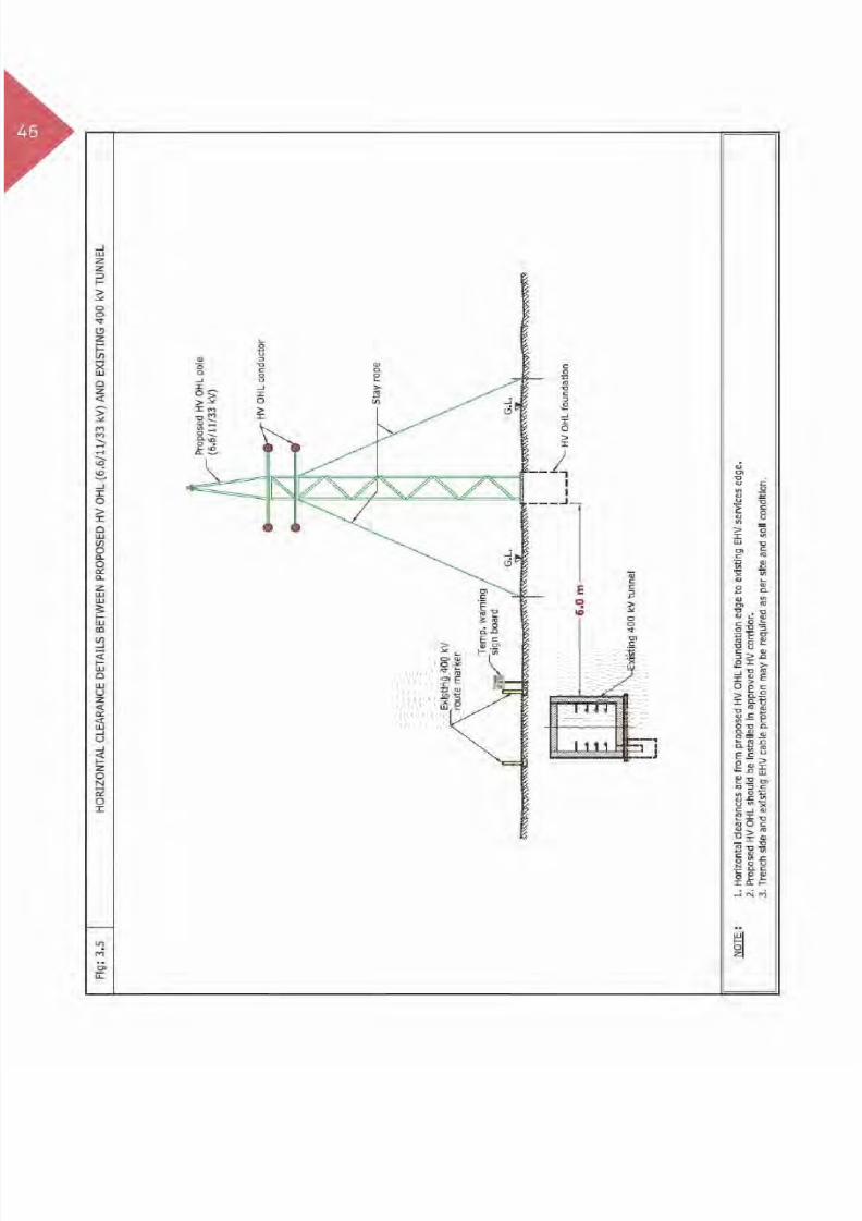
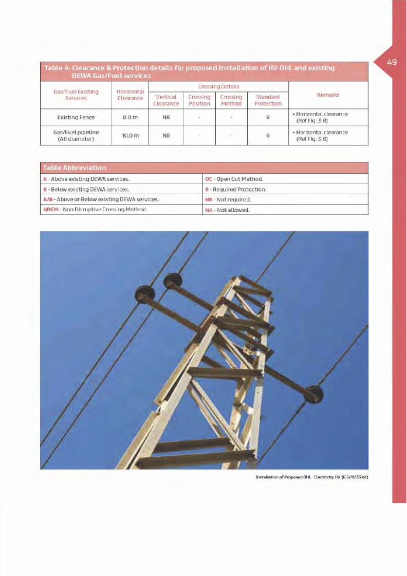
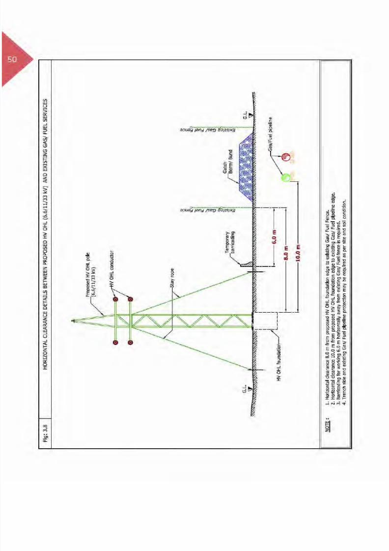
7. Installation of Proposed OHL -Electricity EHV (132/400 kV)
7.1 Introduction
An overhead power line is a structure constructedwithin DEWA Over Head Line corridor/specialreservation and made of a steel structure which issupported by a concrete foundation. An EHV OverHead Line is used to operate and ensure the efficientelectric power transmission for large distances andconsists of suspended conductors over steel towers(Pylons). DEWA Extra High Voltage (EHV) Over HeadLines are two types 132 kV & 400 kV Lines.
To maintain integrity, safety of the structure andpersonnel during various construction activities it isrequired to maintain adequate clearances betweenenergised conductor/Pylons and proposed work as perspecified standards.
Photo: EHV Over Head Line
Installation of Proposed OHL - Electricity EHV (132/400 kV)

8/15/2019 Dewa Latest Reg 2014
http://slidepdf.com/reader/full/dewa-latest-reg-2014 126/817

8/15/2019 Dewa Latest Reg 2014
http://slidepdf.com/reader/full/dewa-latest-reg-2014 127/817

8/15/2019 Dewa Latest Reg 2014
http://slidepdf.com/reader/full/dewa-latest-reg-2014 128/817

8/15/2019 Dewa Latest Reg 2014
http://slidepdf.com/reader/full/dewa-latest-reg-2014 129/817

8/15/2019 Dewa Latest Reg 2014
http://slidepdf.com/reader/full/dewa-latest-reg-2014 130/817

8/15/2019 Dewa Latest Reg 2014
http://slidepdf.com/reader/full/dewa-latest-reg-2014 131/817
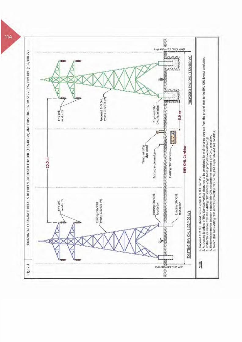
113Table 3: Clearance & Protection details for proposed Installation of EHV-OHL and existing
DEWA Electricity EHV services
Electricity EHV Existing
Services
Horizontal
Clearance
Crossing DetailsRemarksVertical
Clearance
Crossing
Position
Crossing
Method
Standard
Protection
EHV (132 kV)
Oil Filled Cable (O.F)5.0 m NR - - R
(Ref Fig: 7.4)
(Ref Fig: 7.4)
EHV (132 kV)
Power/Pilot/F.O Cable
(Directly Buried)
5.0 m NR - - R
(Ref Fig: 7.4)
(Ref Fig: 7.4)
EHV (132 kV) Trough 5.0 m NR - - R
(Ref Fig: 7.4)
(Ref Fig: 7.4)
EHV (132 kV) Duct Bank 5.0 m NR - - R
(Ref Fig: 7.4)
(Ref Fig: 7.4)
EHV (132 kV)
Joint Bay/Transition
Joint
5.0 m NR - - R
(Ref Fig: 7.4)
(Ref Fig: 7.4)
EHV (132 kV) O.H.L
20.0 m
6.0 m
A/B - R
(Ref Fig: 7.4)
(Ref Fig: 7.5 & photo 7.1)EHV (400 kV) O.H.L 8.0 m
EHV (400 kV) Tunnel 20.0 m NR - - R
(Ref Fig: 7.7)
Clearance & Protection details for access under Existing EHV-OHL
EHV (132 kV) O.H.L
5.0 m
4.5 m
B - R
(Ref Fig: 7.6)
(Ref Fig: 7.6)
(Ref Fig: 7.6)EHV (400 kV) O.H.L 7.5 m
Table Abbreviation
A - Above existing DEWA services. OC - Open Cut Method.
B - Below existing DEWA services. R - Required Protection.
A/B - Above or Below existing DEWA services. NR - Not required.
NDCM - Non Disruptive Crossing Method. NA - Not allowed.
Installation of Proposed OHL - Electricity EHV (132/400 kV)
8/15/2019 Dewa Latest Reg 2014
http://slidepdf.com/reader/full/dewa-latest-reg-2014 132/817

8/15/2019 Dewa Latest Reg 2014
http://slidepdf.com/reader/full/dewa-latest-reg-2014 133/817

8/15/2019 Dewa Latest Reg 2014
http://slidepdf.com/reader/full/dewa-latest-reg-2014 134/817

8/15/2019 Dewa Latest Reg 2014
http://slidepdf.com/reader/full/dewa-latest-reg-2014 135/817

8/15/2019 Dewa Latest Reg 2014
http://slidepdf.com/reader/full/dewa-latest-reg-2014 136/817

8/15/2019 Dewa Latest Reg 2014
http://slidepdf.com/reader/full/dewa-latest-reg-2014 137/817

8/15/2019 Dewa Latest Reg 2014
http://slidepdf.com/reader/full/dewa-latest-reg-2014 138/817

8/15/2019 Dewa Latest Reg 2014
http://slidepdf.com/reader/full/dewa-latest-reg-2014 139/817
121
8. Laying of Proposed Utilities -Water Distribution Pipelines
8.1 Introduction
(100 mm to 450 mm Dia)
Distribution system is used to carry potable water fromtransmission network/storage tanks to the end users;it consists of distribution pipelines, valve chambersetc. Distribution pipelines are always pressurisedto transmit potable water through various pipelinediameters which vary from 100 mm to 450 mm, andare laid with different types of pipelines materials(i.e. FC, AC, GRP, GRE, HDPE, .etc).
These lines are laid in specific corridors withinRight Of Way; therefore during laying activities itis required to protect existing DEWA assets as perspecified standards.
Water Distribution Line
Laying of Proposed Utilities - Water Distribution Pipelines

8/15/2019 Dewa Latest Reg 2014
http://slidepdf.com/reader/full/dewa-latest-reg-2014 140/817

8/15/2019 Dewa Latest Reg 2014
http://slidepdf.com/reader/full/dewa-latest-reg-2014 141/817

8/15/2019 Dewa Latest Reg 2014
http://slidepdf.com/reader/full/dewa-latest-reg-2014 142/817

8/15/2019 Dewa Latest Reg 2014
http://slidepdf.com/reader/full/dewa-latest-reg-2014 143/817
125Table 2: Clearance & Protection details for proposed Distribution Water Pipeline
(100 mm to 450 mm Dia) and existing DEWA Electricity HV services
Electricity HV existing
Services
Horizontal
Clearance
Crossing DetailsRemarksVertical
Clearance
Crossing
Position
Crossing
Method
Standard
Protection
HV
(6.6/11/33 kV) Power/
Pilot Cable and Joints
1.0 m 0.5 m B OC R
(Ref Fig: 8.2, Case 1)
(Ref Fig: 8.3, Case 2)
(Ref Fig: 8.3)
HV
(6.6/11/33 kV) Manhole1.0 m NA - - R
(Ref Fig: 8.2, Case 2)
HV(6.6/11/33 kV) O.H.L
5.0 m NR - - R (Ref Fig: 8.4)
Clearance & Protection details for access and working under Existing HV-OHL
HV
(6.6/11 kV) O.H.L
5.0 m
3.0 m
B - R
(Ref Fig: 8.4)
(Ref Fig: 8.4)
(Ref Fig: 8.4)
HV
(33 kV) O.H.L3.5 m
Table Abbreviation
A - Above existing DEWA services. OC - Open Cut Method.
B - Below existing DEWA services. R - Required Protection.
A/B - Above or Below existing DEWA services. NR - Not required.
NDCM - Non Disruptive Crossing Method. NA - Not allowed.
Laying of Proposed Utilities - Water Distribution Pipelines

8/15/2019 Dewa Latest Reg 2014
http://slidepdf.com/reader/full/dewa-latest-reg-2014 144/817

8/15/2019 Dewa Latest Reg 2014
http://slidepdf.com/reader/full/dewa-latest-reg-2014 145/817

8/15/2019 Dewa Latest Reg 2014
http://slidepdf.com/reader/full/dewa-latest-reg-2014 146/817

8/15/2019 Dewa Latest Reg 2014
http://slidepdf.com/reader/full/dewa-latest-reg-2014 147/817
129Table 3: Clearance & Protection details for proposed Distribution Water Pipeline
(100 mm to 450 mm Dia) and existing DEWA Electricity EHV services
Electricity EHV
existing Services
Horizontal
Clearance
Crossing DetailsRemarksVertical
Clearance
Crossing
Position
Crossing
Method
Standard
Protection
EHV (132 kV)
Oil Filled Cable
(O.F)
1.0 m 0.5 m B OC R
(Ref Fig: 8.9 & 8.10)
EHV (132 kV)
Power/Pilot/
F.O Cable
(Directly Buried)
1.0 m 0.5 m B OC R
(Ref Fig: 8.9 & 8.10)
EHV (132 kV)
Trough1.0 m 0.5 m B OC R
(Ref Fig: 8.8 & 8.10)
EHV (132 kV)
Duct Bank1.0 m 0.5 m B OC R
(Ref Fig: 8.8 & 8.10)
EHV (132 kV)
Joint Bay/
Transition Joint
1.0 m NA - - -
EHV (132/400 kV)
O.H.L5.0 m NR - - R
EHV (400 kV)
Tunnel2.5 m
1.0 m A OC
R
2.0 m B NDCM
Clearance & Protection details for access and working under Existing EHV-OHL
EHV (132 kV) O.H.L5.0 m
4.5 mB - R
EHV (400 kV) O.H.L 7.5 m
Table Abbreviation
A - Above existing DEWA services. OC - Open Cut Method.
B - Below existing DEWA services. R - Required Protection.
A/B - Above or Below existing DEWA services. NR - Not required.
NDCM - Non Disruptive Crossing Method. NA - Not allowed.
Laying of Proposed Utilities - Water Distribution Pipelines

8/15/2019 Dewa Latest Reg 2014
http://slidepdf.com/reader/full/dewa-latest-reg-2014 148/817

8/15/2019 Dewa Latest Reg 2014
http://slidepdf.com/reader/full/dewa-latest-reg-2014 149/817

8/15/2019 Dewa Latest Reg 2014
http://slidepdf.com/reader/full/dewa-latest-reg-2014 150/817

8/15/2019 Dewa Latest Reg 2014
http://slidepdf.com/reader/full/dewa-latest-reg-2014 151/817

8/15/2019 Dewa Latest Reg 2014
http://slidepdf.com/reader/full/dewa-latest-reg-2014 152/817

8/15/2019 Dewa Latest Reg 2014
http://slidepdf.com/reader/full/dewa-latest-reg-2014 153/817

8/15/2019 Dewa Latest Reg 2014
http://slidepdf.com/reader/full/dewa-latest-reg-2014 154/817

8/15/2019 Dewa Latest Reg 2014
http://slidepdf.com/reader/full/dewa-latest-reg-2014 155/817

8/15/2019 Dewa Latest Reg 2014
http://slidepdf.com/reader/full/dewa-latest-reg-2014 156/817

8/15/2019 Dewa Latest Reg 2014
http://slidepdf.com/reader/full/dewa-latest-reg-2014 157/817
139
9. Laying of Proposed Utilities -Water Transmission Pipelines
9.1 Introduction
(500 mm to 1200 mm Dia.)
Transmission system is used to carry bulk quantity ofpotable water for long distances from generation/water treatment plant/reservoir to distribution systemand/or storage reservoir; it consists of transmissionpipelines, valves, chambers etc. Transmission pipelinesare pressurised to transmit potable water throughvarious pipeline diameters varies from 500 mm,550 mm, 600 mm, 700 mm, 900 mm and 1200 mm,
and laid with different types of pipelines materials(i.e. FC, AC, GRP, GRE, HDPE, .etc).
These lines are laid in specific corridors within RightOf Way/ utility reservation; therefore during layingactivities it is required to protect existing DEWA assetsas per specified standards.
Transmission Water Pipeline
Laying of Proposed Utilities - Water Transmission Pipelines

8/15/2019 Dewa Latest Reg 2014
http://slidepdf.com/reader/full/dewa-latest-reg-2014 158/817

8/15/2019 Dewa Latest Reg 2014
http://slidepdf.com/reader/full/dewa-latest-reg-2014 159/817
8/15/2019 Dewa Latest Reg 2014
http://slidepdf.com/reader/full/dewa-latest-reg-2014 160/817

8/15/2019 Dewa Latest Reg 2014
http://slidepdf.com/reader/full/dewa-latest-reg-2014 161/817

8/15/2019 Dewa Latest Reg 2014
http://slidepdf.com/reader/full/dewa-latest-reg-2014 162/817

8/15/2019 Dewa Latest Reg 2014
http://slidepdf.com/reader/full/dewa-latest-reg-2014 163/817

8/15/2019 Dewa Latest Reg 2014
http://slidepdf.com/reader/full/dewa-latest-reg-2014 164/817

8/15/2019 Dewa Latest Reg 2014
http://slidepdf.com/reader/full/dewa-latest-reg-2014 165/817

8/15/2019 Dewa Latest Reg 2014
http://slidepdf.com/reader/full/dewa-latest-reg-2014 166/817
8/15/2019 Dewa Latest Reg 2014
http://slidepdf.com/reader/full/dewa-latest-reg-2014 167/817

8/15/2019 Dewa Latest Reg 2014
http://slidepdf.com/reader/full/dewa-latest-reg-2014 168/817

8/15/2019 Dewa Latest Reg 2014
http://slidepdf.com/reader/full/dewa-latest-reg-2014 169/817

8/15/2019 Dewa Latest Reg 2014
http://slidepdf.com/reader/full/dewa-latest-reg-2014 170/817

8/15/2019 Dewa Latest Reg 2014
http://slidepdf.com/reader/full/dewa-latest-reg-2014 171/817

8/15/2019 Dewa Latest Reg 2014
http://slidepdf.com/reader/full/dewa-latest-reg-2014 172/817

8/15/2019 Dewa Latest Reg 2014
http://slidepdf.com/reader/full/dewa-latest-reg-2014 173/817
8/15/2019 Dewa Latest Reg 2014
http://slidepdf.com/reader/full/dewa-latest-reg-2014 174/817

8/15/2019 Dewa Latest Reg 2014
http://slidepdf.com/reader/full/dewa-latest-reg-2014 175/817

8/15/2019 Dewa Latest Reg 2014
http://slidepdf.com/reader/full/dewa-latest-reg-2014 176/817

8/15/2019 Dewa Latest Reg 2014
http://slidepdf.com/reader/full/dewa-latest-reg-2014 177/817
159
10. Laying of Proposed Utilities -Sewerage Gravity Pipelines
10.1 Introduction
The purpose of Sewerage system is to receive andtransport waste water (effluents) coming fromresidential, commercial and industrial areas throughunderground sewerage pipelines to the dedicatedsewerage treatment plant. It consists of a network ofgravity and pressure pipelines of various diameters.The gravity lines have a large network of undergroundpipes with branches and manholes and these pipelines
are laid at a certain depth in order to meet thegravity gradients.
Gravity pipelines are laid in dedicated corridorswithin Right Of Way, therefore during layingactivities it is required to protect DEWA assets as perspecified standards.
Laying Sewerage Gravity line
Laying of Proposed Utility - Sewerage Gravity Pipelines
8/15/2019 Dewa Latest Reg 2014
http://slidepdf.com/reader/full/dewa-latest-reg-2014 178/817

8/15/2019 Dewa Latest Reg 2014
http://slidepdf.com/reader/full/dewa-latest-reg-2014 179/817

8/15/2019 Dewa Latest Reg 2014
http://slidepdf.com/reader/full/dewa-latest-reg-2014 180/817

8/15/2019 Dewa Latest Reg 2014
http://slidepdf.com/reader/full/dewa-latest-reg-2014 181/817

8/15/2019 Dewa Latest Reg 2014
http://slidepdf.com/reader/full/dewa-latest-reg-2014 182/817

8/15/2019 Dewa Latest Reg 2014
http://slidepdf.com/reader/full/dewa-latest-reg-2014 183/817

8/15/2019 Dewa Latest Reg 2014
http://slidepdf.com/reader/full/dewa-latest-reg-2014 184/817

8/15/2019 Dewa Latest Reg 2014
http://slidepdf.com/reader/full/dewa-latest-reg-2014 185/817

8/15/2019 Dewa Latest Reg 2014
http://slidepdf.com/reader/full/dewa-latest-reg-2014 186/817

8/15/2019 Dewa Latest Reg 2014
http://slidepdf.com/reader/full/dewa-latest-reg-2014 187/817

8/15/2019 Dewa Latest Reg 2014
http://slidepdf.com/reader/full/dewa-latest-reg-2014 188/817

8/15/2019 Dewa Latest Reg 2014
http://slidepdf.com/reader/full/dewa-latest-reg-2014 189/817

8/15/2019 Dewa Latest Reg 2014
http://slidepdf.com/reader/full/dewa-latest-reg-2014 190/817

8/15/2019 Dewa Latest Reg 2014
http://slidepdf.com/reader/full/dewa-latest-reg-2014 191/817

8/15/2019 Dewa Latest Reg 2014
http://slidepdf.com/reader/full/dewa-latest-reg-2014 192/817

8/15/2019 Dewa Latest Reg 2014
http://slidepdf.com/reader/full/dewa-latest-reg-2014 193/817
175
11. Laying of Proposed Utilities -Sewerage Pressure Pipelines
11.1 Introduction
The prime elements of Sewerage system are receivingand draining waste water (effluents) away fromresidential and industrial areas and such raw seweragewater transported to the dedicated treatment plant.The sewer system consists of pipe network of thegravity line as well as the pressure line.
Sewer pressure lines are connected to seweragepumping station which regulates at a desired pressureto transmit the effulent to the treatment plant.
Generally pressure lines are transmission lines whichcarry effulent for longer distance to the treatmentplant and will have lifting station/pumping station inthe network depending on the ground profiles. Thesewerage lines are a large network of undergroundpipes, usually laid in greater depth. The sewerpressure pipeline lays in an approved corridor withinRight Of Way; therefore it is required to protectDEWA existing assets during laying activities as perspecified standard.
Laying of Sewerage Pipeline
Laying of Proposed Utility - Sewerage Pressure Pipelines

8/15/2019 Dewa Latest Reg 2014
http://slidepdf.com/reader/full/dewa-latest-reg-2014 194/817

8/15/2019 Dewa Latest Reg 2014
http://slidepdf.com/reader/full/dewa-latest-reg-2014 195/817

8/15/2019 Dewa Latest Reg 2014
http://slidepdf.com/reader/full/dewa-latest-reg-2014 196/817

8/15/2019 Dewa Latest Reg 2014
http://slidepdf.com/reader/full/dewa-latest-reg-2014 197/817

8/15/2019 Dewa Latest Reg 2014
http://slidepdf.com/reader/full/dewa-latest-reg-2014 198/817

8/15/2019 Dewa Latest Reg 2014
http://slidepdf.com/reader/full/dewa-latest-reg-2014 199/817

8/15/2019 Dewa Latest Reg 2014
http://slidepdf.com/reader/full/dewa-latest-reg-2014 200/817

8/15/2019 Dewa Latest Reg 2014
http://slidepdf.com/reader/full/dewa-latest-reg-2014 201/817

8/15/2019 Dewa Latest Reg 2014
http://slidepdf.com/reader/full/dewa-latest-reg-2014 202/817

8/15/2019 Dewa Latest Reg 2014
http://slidepdf.com/reader/full/dewa-latest-reg-2014 203/817

8/15/2019 Dewa Latest Reg 2014
http://slidepdf.com/reader/full/dewa-latest-reg-2014 204/817

8/15/2019 Dewa Latest Reg 2014
http://slidepdf.com/reader/full/dewa-latest-reg-2014 205/817

8/15/2019 Dewa Latest Reg 2014
http://slidepdf.com/reader/full/dewa-latest-reg-2014 206/817

8/15/2019 Dewa Latest Reg 2014
http://slidepdf.com/reader/full/dewa-latest-reg-2014 207/817

8/15/2019 Dewa Latest Reg 2014
http://slidepdf.com/reader/full/dewa-latest-reg-2014 208/817

8/15/2019 Dewa Latest Reg 2014
http://slidepdf.com/reader/full/dewa-latest-reg-2014 209/817

8/15/2019 Dewa Latest Reg 2014
http://slidepdf.com/reader/full/dewa-latest-reg-2014 210/817

8/15/2019 Dewa Latest Reg 2014
http://slidepdf.com/reader/full/dewa-latest-reg-2014 211/817

8/15/2019 Dewa Latest Reg 2014
http://slidepdf.com/reader/full/dewa-latest-reg-2014 212/817

8/15/2019 Dewa Latest Reg 2014
http://slidepdf.com/reader/full/dewa-latest-reg-2014 213/817

8/15/2019 Dewa Latest Reg 2014
http://slidepdf.com/reader/full/dewa-latest-reg-2014 214/817

8/15/2019 Dewa Latest Reg 2014
http://slidepdf.com/reader/full/dewa-latest-reg-2014 215/817
197Table 2: Clearance & Protection details for Proposed Drainage Gravity Pipeline and existing
DEWA Electricity HV services
Electricity HV existing
Services
Horizontal
Clearance
Crossing DetailsRemarksVertical
Clearance
Crossing
Position
Crossing
Method
Standard
Protection
HV
(6.6/11/33 kV) Power/
Pilot Cable and Joints
1.0 m 0.5 m B OC R
(Ref Fig: 12.2, Case 1)
(Ref Fig: 12.3, Case 2)
(Ref Fig: 12.3)
HV
(6.6/11/33 kV) Manhole1.0 m NA - - R
(Ref Fig: 12.2, Case 2)
HV(6.6/11/33 kV) O.H.L
5.0 m NR - - R (Ref Fig: 12.4)
Clearance & Protection details for access and working under Existing HV-OHL
HV
(6.6/11 kV) O.H.L
5.0 m
3.0 m
B - R
(Ref Fig: 12.4)
(Ref Fig: 12.4)
(Ref Fig: 12.4)
HV
(33 kV) O.H.L3.5 m
Table Abbreviation
A - Above existing DEWA services. OC - Open Cut Method.
B - Below existing DEWA services. R - Required Protection.
A/B - Above or Below existing DEWA services. NR - Not required.
NDCM - Non Disruptive Crossing Method. NA - Not allowed.
Laying of Proposed Utility - Drainage Gravity Pipelines

8/15/2019 Dewa Latest Reg 2014
http://slidepdf.com/reader/full/dewa-latest-reg-2014 216/817

8/15/2019 Dewa Latest Reg 2014
http://slidepdf.com/reader/full/dewa-latest-reg-2014 217/817
8/15/2019 Dewa Latest Reg 2014
http://slidepdf.com/reader/full/dewa-latest-reg-2014 218/817

8/15/2019 Dewa Latest Reg 2014
http://slidepdf.com/reader/full/dewa-latest-reg-2014 219/817
201Table 3: Clearance & Protection details for proposed Drainage gravity pipeline and existing DEWA
Electricity EHV services
Electricity EHVexisting Services
HorizontalClearance
Crossing Details
RemarksVertical
Clearance
Crossing
Position
Crossing
Method
Standard
Protection
EHV (132 kV)
Oil Filled Cable(O.F)1.0 m 0.5 m B OC R
EHV (132 kV)
Power/Pilot/
F.O Cable
(Directly Buried)
1.0 m 0.5 m B OC R
EHV (132 kV) Trough 1.0 m 0.5 m B OC R
EHV (132 kV)
Duct Bank1.0 m 0.5 m B OC R
EHV (132 kV)
Joint Bay/ Transition
Joint
1.0 m NA - - R
EHV (132/400 kV)
O.H.L5.0 m NR - - R
EHV (400 kV) Tunnel 2.5 m
1.0 m A OC
R
2.0 m B NDCM
Clearance & Protection details for access and working under Existing EHV-OHL
EHV (132 kV) O.H.L
5.0 m
4.5 m
B - R
EHV (400 kV) O.H.L 7.5 m
Table Abbreviation
A - Above existing DEWA services. OC - Open Cut Method.
B - Below existing DEWA services. R - Required Protection.
A/B - Above or Below existing DEWA services. NR - Not required.
NDCM - Non Disruptive Crossing Method. NA - Not allowed.
Laying of Proposed Utility - Drainage Gravity Pipelines
8/15/2019 Dewa Latest Reg 2014
http://slidepdf.com/reader/full/dewa-latest-reg-2014 220/817

8/15/2019 Dewa Latest Reg 2014
http://slidepdf.com/reader/full/dewa-latest-reg-2014 221/817

8/15/2019 Dewa Latest Reg 2014
http://slidepdf.com/reader/full/dewa-latest-reg-2014 222/817

8/15/2019 Dewa Latest Reg 2014
http://slidepdf.com/reader/full/dewa-latest-reg-2014 223/817

8/15/2019 Dewa Latest Reg 2014
http://slidepdf.com/reader/full/dewa-latest-reg-2014 224/817

8/15/2019 Dewa Latest Reg 2014
http://slidepdf.com/reader/full/dewa-latest-reg-2014 225/817

8/15/2019 Dewa Latest Reg 2014
http://slidepdf.com/reader/full/dewa-latest-reg-2014 226/817

8/15/2019 Dewa Latest Reg 2014
http://slidepdf.com/reader/full/dewa-latest-reg-2014 227/817

8/15/2019 Dewa Latest Reg 2014
http://slidepdf.com/reader/full/dewa-latest-reg-2014 228/817

8/15/2019 Dewa Latest Reg 2014
http://slidepdf.com/reader/full/dewa-latest-reg-2014 229/817

8/15/2019 Dewa Latest Reg 2014
http://slidepdf.com/reader/full/dewa-latest-reg-2014 230/817

8/15/2019 Dewa Latest Reg 2014
http://slidepdf.com/reader/full/dewa-latest-reg-2014 231/817
213Table 2: Clearance & Protection details for proposed Drainage pressure pipeline and existing
DEWA Electricity HV services
Electricity HV existing
Services
Horizontal
Clearance
Crossing DetailsRemarksVertical
Clearance
Crossing
Position
Crossing
Method
Standard
Protection
HV
(6.6/11/33 kV) Power/
Pilot Cable and Joints
2.0 m 1.0 m B OC R
(Ref Fig: 13.2, Case 1)
(Ref Fig: 13.3, Case 2)
(Ref Fig: 13.3)
HV
(6.6/11/33 kV) Manhole2.0 m NA - - R
(Ref Fig: 13.2, Case 2)
HV
(6.6/11/33 kV) O.H.L5.0 m NR - - R
(Ref Fig: 13.4)
(Ref Fig: 13.4)
Clearance & Protection details for access and working under Existing HV-OHL
HV
(6.6/11 kV) O.H.L
5.0 m
3.0 m
B - R
(Ref Fig: 13.4)
(Ref Fig: 13.4)
(Ref Fig: 13.4)
HV
(33 kV) O.H.L3.5 m
Table Abbreviation
A - Above existing DEWA services. OC - Open Cut Method.
B - Below existing DEWA services. R - Required Protection.
A/B - Above or Below existing DEWA services. NR - Not required.
NDCM - Non Disruptive Crossing Method. NA - Not allowed.
Laying of Proposed Utility - Drainage Pressure Pipelines

8/15/2019 Dewa Latest Reg 2014
http://slidepdf.com/reader/full/dewa-latest-reg-2014 232/817

8/15/2019 Dewa Latest Reg 2014
http://slidepdf.com/reader/full/dewa-latest-reg-2014 233/817

8/15/2019 Dewa Latest Reg 2014
http://slidepdf.com/reader/full/dewa-latest-reg-2014 234/817

8/15/2019 Dewa Latest Reg 2014
http://slidepdf.com/reader/full/dewa-latest-reg-2014 235/817
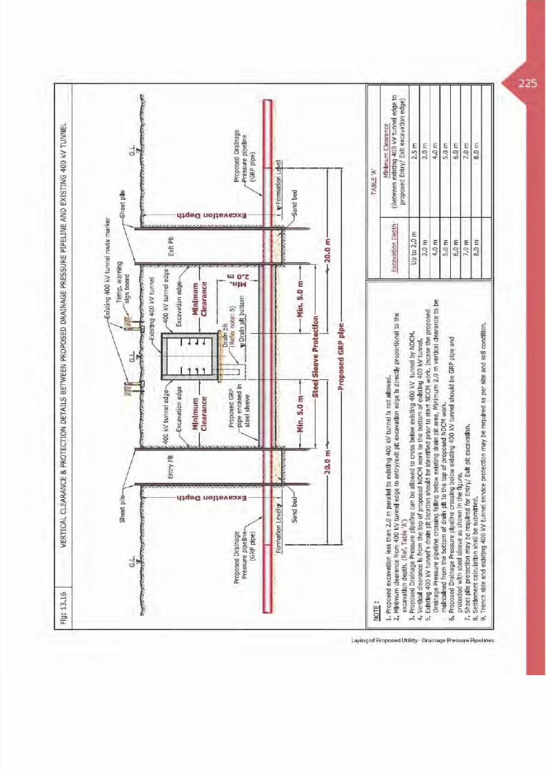
217Table 3: Clearance & Protection details for Proposed Drainage Pressure pipeline and existing
DEWA Electricity EHV services
Electricity EHV
existing Services
Horizontal
Clearance
Crossing DetailsRemarksVertical
Clearance
Crossing
Position
Crossing
Method
Standard
Protection
EHV (132 kV)
Oil Filled
Cable(O.F)
3.0 m 1.0 m B OC R
EHV (132 kV)
Power/Pilot/
F.O Cable
(Directly Buried)
3.0 m 0.5 m B OC R
EHV (132 kV)
Trough 3.0 m 1.0 m B OC R
(Ref Fig: 13.11, 13.12 & 13.13)
EHV (132 kV)
Duct Bank3.0 m 0.5 m B OC R
EHV (132 kV)
Joint Bay/
Transition Joint
3.0 m NA - - R
EHV (132/400 kV)
O.H.L5.0 m NR - - R
EHV (400 kV)
Tunnel2.5 m
1.0 m A OCR
2.0 m B NDCM
Clearance & Protection details for access and working under Existing EHV-OHL
EHV (132 kV)
O.H.L5.0 m
4.5 m
B - R
EHV (400 kV)
O.H.L7.5 m
Table Abbreviation
A - Above existing DEWA services. OC - Open Cut Method.
B - Below existing DEWA services. R - Required Protection.
A/B - Above or Below existing DEWA services. NR - Not required.
NDCM - Non Disruptive Crossing Method. NA - Not allowed.
Laying of Proposed Utility - Drainage Pressure Pipelines
8/15/2019 Dewa Latest Reg 2014
http://slidepdf.com/reader/full/dewa-latest-reg-2014 236/817

8/15/2019 Dewa Latest Reg 2014
http://slidepdf.com/reader/full/dewa-latest-reg-2014 237/817

8/15/2019 Dewa Latest Reg 2014
http://slidepdf.com/reader/full/dewa-latest-reg-2014 238/817

8/15/2019 Dewa Latest Reg 2014
http://slidepdf.com/reader/full/dewa-latest-reg-2014 239/817

8/15/2019 Dewa Latest Reg 2014
http://slidepdf.com/reader/full/dewa-latest-reg-2014 240/817

8/15/2019 Dewa Latest Reg 2014
http://slidepdf.com/reader/full/dewa-latest-reg-2014 241/817

8/15/2019 Dewa Latest Reg 2014
http://slidepdf.com/reader/full/dewa-latest-reg-2014 242/817
8/15/2019 Dewa Latest Reg 2014
http://slidepdf.com/reader/full/dewa-latest-reg-2014 243/817

8/15/2019 Dewa Latest Reg 2014
http://slidepdf.com/reader/full/dewa-latest-reg-2014 244/817

8/15/2019 Dewa Latest Reg 2014
http://slidepdf.com/reader/full/dewa-latest-reg-2014 245/817

8/15/2019 Dewa Latest Reg 2014
http://slidepdf.com/reader/full/dewa-latest-reg-2014 246/817

8/15/2019 Dewa Latest Reg 2014
http://slidepdf.com/reader/full/dewa-latest-reg-2014 247/817
229
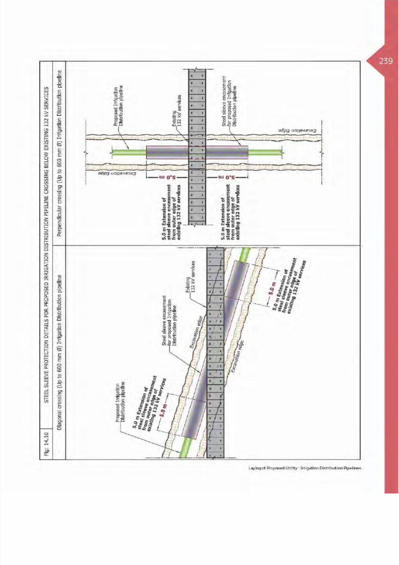
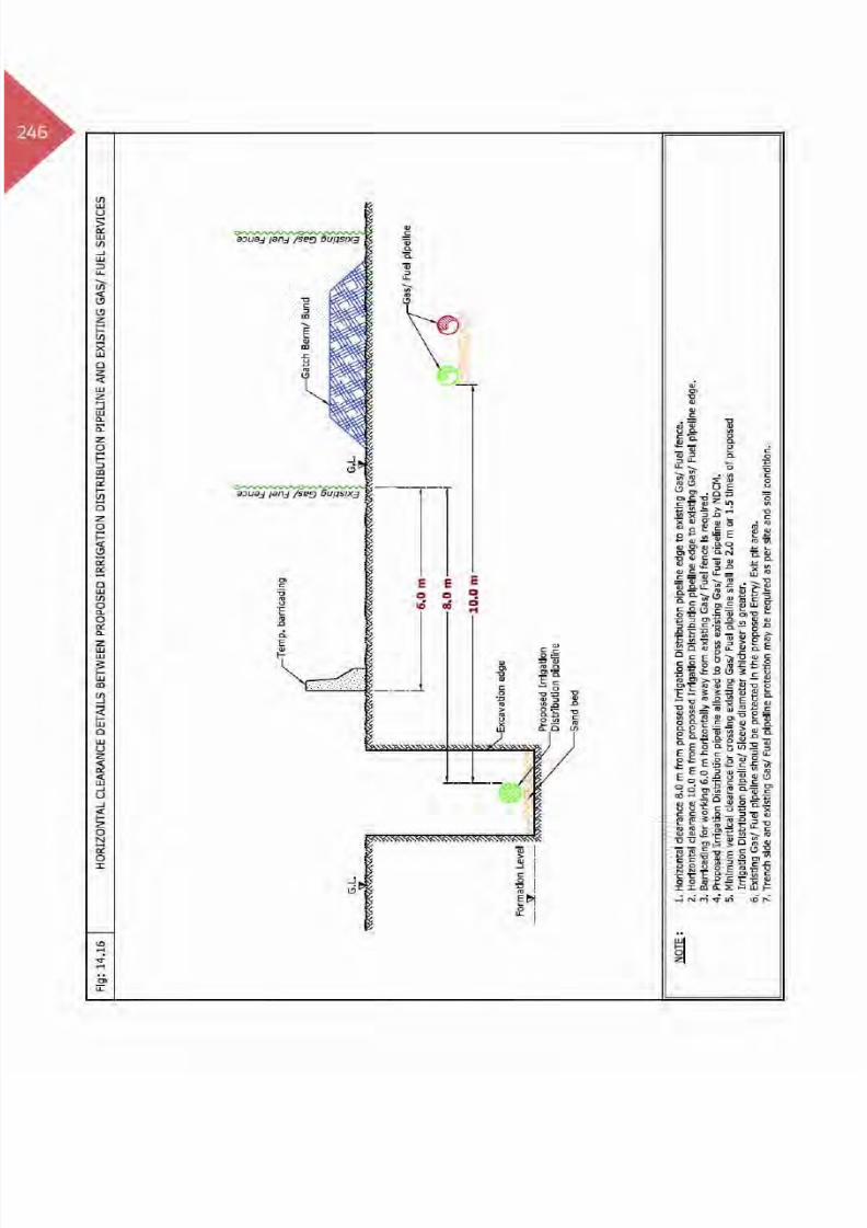
14. Laying of Proposed Utilities -Irrigation Distribution Pipelines
14.1 Introduction
The purpose of the irrigation distribution networkis to irrigate the green landscaping areas, trees,plantation etc., by treated irrigation water thattransmitted from the main networks.
This network consists of distribution pipelines withvarious diameters of different materials, valves,
and chambers etc., which are constructed within adedicated corridor in Right Of Way. Therefore duringconstruction activities it is required to protect DEWAexisting assets as per specified standards.
Laying Irrigation Distribution Network
Laying of Proposed Utility - Irrigation Distribution Pipelines

8/15/2019 Dewa Latest Reg 2014
http://slidepdf.com/reader/full/dewa-latest-reg-2014 248/817

8/15/2019 Dewa Latest Reg 2014
http://slidepdf.com/reader/full/dewa-latest-reg-2014 249/817

8/15/2019 Dewa Latest Reg 2014
http://slidepdf.com/reader/full/dewa-latest-reg-2014 250/817

8/15/2019 Dewa Latest Reg 2014
http://slidepdf.com/reader/full/dewa-latest-reg-2014 251/817

8/15/2019 Dewa Latest Reg 2014
http://slidepdf.com/reader/full/dewa-latest-reg-2014 252/817

8/15/2019 Dewa Latest Reg 2014
http://slidepdf.com/reader/full/dewa-latest-reg-2014 253/817

8/15/2019 Dewa Latest Reg 2014
http://slidepdf.com/reader/full/dewa-latest-reg-2014 254/817

8/15/2019 Dewa Latest Reg 2014
http://slidepdf.com/reader/full/dewa-latest-reg-2014 255/817

8/15/2019 Dewa Latest Reg 2014
http://slidepdf.com/reader/full/dewa-latest-reg-2014 256/817
8/15/2019 Dewa Latest Reg 2014
http://slidepdf.com/reader/full/dewa-latest-reg-2014 257/817

8/15/2019 Dewa Latest Reg 2014
http://slidepdf.com/reader/full/dewa-latest-reg-2014 258/817

8/15/2019 Dewa Latest Reg 2014
http://slidepdf.com/reader/full/dewa-latest-reg-2014 259/817

8/15/2019 Dewa Latest Reg 2014
http://slidepdf.com/reader/full/dewa-latest-reg-2014 260/817

8/15/2019 Dewa Latest Reg 2014
http://slidepdf.com/reader/full/dewa-latest-reg-2014 261/817

8/15/2019 Dewa Latest Reg 2014
http://slidepdf.com/reader/full/dewa-latest-reg-2014 262/817

8/15/2019 Dewa Latest Reg 2014
http://slidepdf.com/reader/full/dewa-latest-reg-2014 263/817
8/15/2019 Dewa Latest Reg 2014
http://slidepdf.com/reader/full/dewa-latest-reg-2014 264/817

8/15/2019 Dewa Latest Reg 2014
http://slidepdf.com/reader/full/dewa-latest-reg-2014 265/817
247
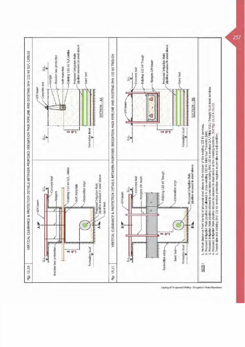
15. Laying of Proposed Utilities -Irrigation Main Pipelines
15.1 Introduction
The purpose of the irrigation main network is totransport the treated water from the treatment plantsto the irrigation distribution networks which are thesecondary irrigation water supply network.
This network consists of main lines (transmissionlines), valves, chambers, pumping station, reservation
tanks etc., and the main lines, valves chambers areconstructed in a dedicated corridor within Right OfWay, and therefore during construction activitiesit is required to protect DEWA existing assets as perspecified standards.
Laying of Irrigation Main Network
Laying of Proposed Utility - Irrigation Main Pipelines

8/15/2019 Dewa Latest Reg 2014
http://slidepdf.com/reader/full/dewa-latest-reg-2014 266/817

8/15/2019 Dewa Latest Reg 2014
http://slidepdf.com/reader/full/dewa-latest-reg-2014 267/817

8/15/2019 Dewa Latest Reg 2014
http://slidepdf.com/reader/full/dewa-latest-reg-2014 268/817

8/15/2019 Dewa Latest Reg 2014
http://slidepdf.com/reader/full/dewa-latest-reg-2014 269/817

8/15/2019 Dewa Latest Reg 2014
http://slidepdf.com/reader/full/dewa-latest-reg-2014 270/817

8/15/2019 Dewa Latest Reg 2014
http://slidepdf.com/reader/full/dewa-latest-reg-2014 271/817

8/15/2019 Dewa Latest Reg 2014
http://slidepdf.com/reader/full/dewa-latest-reg-2014 272/817

8/15/2019 Dewa Latest Reg 2014
http://slidepdf.com/reader/full/dewa-latest-reg-2014 273/817

8/15/2019 Dewa Latest Reg 2014
http://slidepdf.com/reader/full/dewa-latest-reg-2014 274/817
8/15/2019 Dewa Latest Reg 2014
http://slidepdf.com/reader/full/dewa-latest-reg-2014 275/817

8/15/2019 Dewa Latest Reg 2014
http://slidepdf.com/reader/full/dewa-latest-reg-2014 276/817

8/15/2019 Dewa Latest Reg 2014
http://slidepdf.com/reader/full/dewa-latest-reg-2014 277/817

8/15/2019 Dewa Latest Reg 2014
http://slidepdf.com/reader/full/dewa-latest-reg-2014 278/817

8/15/2019 Dewa Latest Reg 2014
http://slidepdf.com/reader/full/dewa-latest-reg-2014 279/817

8/15/2019 Dewa Latest Reg 2014
http://slidepdf.com/reader/full/dewa-latest-reg-2014 280/817

8/15/2019 Dewa Latest Reg 2014
http://slidepdf.com/reader/full/dewa-latest-reg-2014 281/817
8/15/2019 Dewa Latest Reg 2014
http://slidepdf.com/reader/full/dewa-latest-reg-2014 282/817

8/15/2019 Dewa Latest Reg 2014
http://slidepdf.com/reader/full/dewa-latest-reg-2014 283/817

8/15/2019 Dewa Latest Reg 2014
http://slidepdf.com/reader/full/dewa-latest-reg-2014 284/817

8/15/2019 Dewa Latest Reg 2014
http://slidepdf.com/reader/full/dewa-latest-reg-2014 285/817

8/15/2019 Dewa Latest Reg 2014
http://slidepdf.com/reader/full/dewa-latest-reg-2014 286/817

8/15/2019 Dewa Latest Reg 2014
http://slidepdf.com/reader/full/dewa-latest-reg-2014 287/817
269Table 2: Clearance & Protection details for proposed District Cooling Pipeline and existing
DEWA Electricity HV services
Electricity HV existing
Services
Horizontal
Clearance
Crossing DetailsRemarksVertical
Clearance
Crossing
Position
Crossing
Method
Standard
Protection
HV
(6.6/11/33 kV) Power/
Pilot Cable and Joints
1.0 m 0.5 m B OC R
(Ref Fig: 16.2)
(Ref Fig: 16.3)
(Ref Fig: 16.4)
HV
(6.6/11/33 kV) Manhole0.5 m NA - - R
(Ref Fig: 16.2)
HV(6.6/11/33 kV) O.H.L
5.0 m NR - - R (Ref Fig: 16.5)
Clearance & Protection details for access and working under Existing HV-OHL
HV
(6.6/11 kV) O.H.L
5.0 m
3.0 m
B - R
(Ref Fig: 16.5)
(Ref Fig: 16.5)
(Ref Fig: 16.5)
HV
(33 kV) O.H.L3.5 m
Table Abbreviation
A - Above existing DEWA services. OC - Open Cut Method.
B - Below existing DEWA services. R - Required Protection.
A/B - Above or Below existing DEWA services. NR - Not required.
NDCM - Non Disruptive Crossing Method. NA - Not allowed.
Laying of Proposed Utilities - District Cooling Pipelines

8/15/2019 Dewa Latest Reg 2014
http://slidepdf.com/reader/full/dewa-latest-reg-2014 288/817

8/15/2019 Dewa Latest Reg 2014
http://slidepdf.com/reader/full/dewa-latest-reg-2014 289/817

8/15/2019 Dewa Latest Reg 2014
http://slidepdf.com/reader/full/dewa-latest-reg-2014 290/817

8/15/2019 Dewa Latest Reg 2014
http://slidepdf.com/reader/full/dewa-latest-reg-2014 291/817
273Table 3: Clearance & Protection details for proposed District Cooling Pipeline and existing
DEWA Electricity EHV services
Electricity EHV
existing Services
Horizontal
Clearance
Crossing DetailsRemarksVertical
Clearance
Crossing
Position
Crossing
Method
Standard
Protection
EHV (132 kV)
Oil Filled Cable
(O.F)
3.0 m 1.0 m B OC R
EHV (132 kV)
Power/Pilot/
F.O Cable
(Directly Buried)
3.0 m 0.5 m B OC R
EHV (132 kV) Trough 3.0 m 1.0 m B OC R
EHV (132 kV)
Duct Bank3.0 m 0.5 m B OC R
EHV (132 kV)
Joint Bay/
Transition Joint
3.0 m NA - - R
EHV (132/400 kV)
O.H.L5.0 m NR - - R
(Ref Fig: 16.14)
EHV (400 kV)
Tunnel2.5 m 2.0 m B NDCM R
(Ref Fig: 16.12)
Clearance & Protection details for access and working under Existing EHV-OHL
EHV (132 kV) O.H.L
5.0 m
4.5 m
B - R
(Ref Fig: 16.14)
EHV (400 kV) O.H.L 7.5 m
Table Abbreviation
A - Above existing DEWA services. OC - Open Cut Method.
B - Below existing DEWA services. R - Required Protection.
A/B - Above or Below existing DEWA services. NR - Not required.
NDCM - Non Disruptive Crossing Method. NA - Not allowed.
Laying of Proposed Utilities - District Cooling Pipelines

8/15/2019 Dewa Latest Reg 2014
http://slidepdf.com/reader/full/dewa-latest-reg-2014 292/817

8/15/2019 Dewa Latest Reg 2014
http://slidepdf.com/reader/full/dewa-latest-reg-2014 293/817

8/15/2019 Dewa Latest Reg 2014
http://slidepdf.com/reader/full/dewa-latest-reg-2014 294/817

8/15/2019 Dewa Latest Reg 2014
http://slidepdf.com/reader/full/dewa-latest-reg-2014 295/817

8/15/2019 Dewa Latest Reg 2014
http://slidepdf.com/reader/full/dewa-latest-reg-2014 296/817

8/15/2019 Dewa Latest Reg 2014
http://slidepdf.com/reader/full/dewa-latest-reg-2014 297/817

8/15/2019 Dewa Latest Reg 2014
http://slidepdf.com/reader/full/dewa-latest-reg-2014 298/817

8/15/2019 Dewa Latest Reg 2014
http://slidepdf.com/reader/full/dewa-latest-reg-2014 299/817

8/15/2019 Dewa Latest Reg 2014
http://slidepdf.com/reader/full/dewa-latest-reg-2014 300/817

8/15/2019 Dewa Latest Reg 2014
http://slidepdf.com/reader/full/dewa-latest-reg-2014 301/817
283
G a s / F u
e l P
i p e i n s i d e
f e n c i n g w
i t h r o u
t e m a r k e
r
G a s / F u
e l G a t c
h b e r m
/ B u
n d a n
d r o u
t e m a r k
e r
Laying of Proposed Utilities - Gas/Fuel Pipelines

8/15/2019 Dewa Latest Reg 2014
http://slidepdf.com/reader/full/dewa-latest-reg-2014 302/817

8/15/2019 Dewa Latest Reg 2014
http://slidepdf.com/reader/full/dewa-latest-reg-2014 303/817

8/15/2019 Dewa Latest Reg 2014
http://slidepdf.com/reader/full/dewa-latest-reg-2014 304/817

8/15/2019 Dewa Latest Reg 2014
http://slidepdf.com/reader/full/dewa-latest-reg-2014 305/817
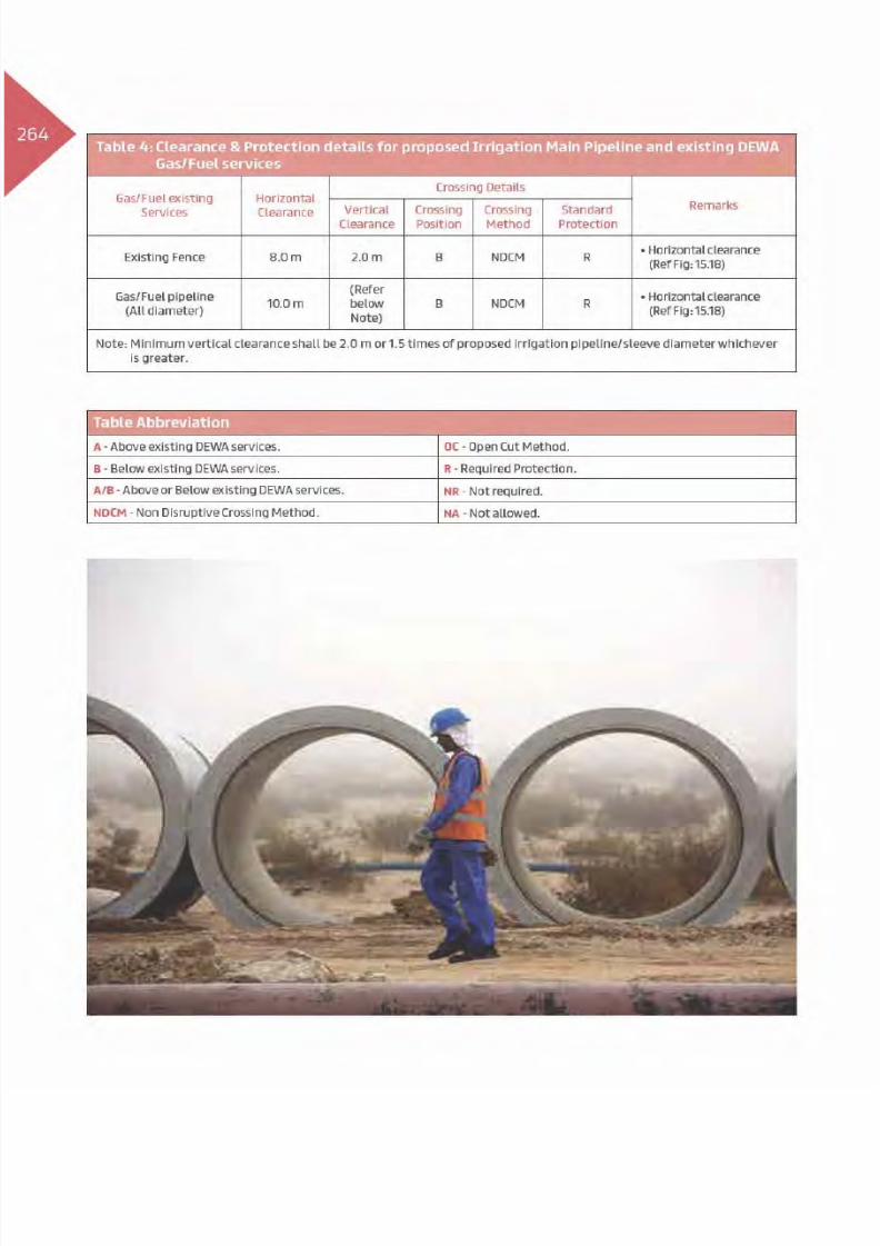
287Table 2: Clearance & Protection details for proposed Gas/Fuel Pipeline and existing
DEWA Electricity HV services
Electricity HV existing
Services
Horizontal
Clearance
Crossing DetailsRemarksVertical
Clearance
Crossing
Position
Crossing
Method
Standard
Protection
HV
(6.6/11/33 kV) Power/
Pilot Cable and Joints
10.0 m 1.0 m B OC R
(Ref Fig: 17.3, Case 1)
(Ref Fig: 17.3, Case 2)
(Ref Fig: 17.3, Case 2)
HV
(6.6/11/33 kV) Manhole10.0 m NA - - R
(Ref Fig: 17.3, Case 3)
HV(6.6/11/33 kV) O.H.L
10.0 m NR - - R (Ref Fig: 17.4)
Clearance & Protection details for access and working under Existing HV-OHL
HV
(6.6/11 kV) O.H.L
10.0 m
3.0 m
B - R
(Ref Fig: 17.4)
(Ref Fig: 17.4)
(Ref Fig: 17.4)
HV
(33 kV) O.H.L3.5 m
Table Abbreviation
A - Above existing DEWA services. OC - Open Cut Method.
B - Below existing DEWA services. R - Required Protection.
A/B - Above or Below existing DEWA services. NR - Not required.
NDCM - Non Disruptive Crossing Method. NA - Not allowed.
Laying of Proposed Utilities - Gas/Fuel Pipelines

8/15/2019 Dewa Latest Reg 2014
http://slidepdf.com/reader/full/dewa-latest-reg-2014 306/817

8/15/2019 Dewa Latest Reg 2014
http://slidepdf.com/reader/full/dewa-latest-reg-2014 307/817

8/15/2019 Dewa Latest Reg 2014
http://slidepdf.com/reader/full/dewa-latest-reg-2014 308/817

8/15/2019 Dewa Latest Reg 2014
http://slidepdf.com/reader/full/dewa-latest-reg-2014 309/817
8/15/2019 Dewa Latest Reg 2014
http://slidepdf.com/reader/full/dewa-latest-reg-2014 310/817

8/15/2019 Dewa Latest Reg 2014
http://slidepdf.com/reader/full/dewa-latest-reg-2014 311/817

8/15/2019 Dewa Latest Reg 2014
http://slidepdf.com/reader/full/dewa-latest-reg-2014 312/817

8/15/2019 Dewa Latest Reg 2014
http://slidepdf.com/reader/full/dewa-latest-reg-2014 313/817

8/15/2019 Dewa Latest Reg 2014
http://slidepdf.com/reader/full/dewa-latest-reg-2014 314/817

8/15/2019 Dewa Latest Reg 2014
http://slidepdf.com/reader/full/dewa-latest-reg-2014 315/817
8/15/2019 Dewa Latest Reg 2014
http://slidepdf.com/reader/full/dewa-latest-reg-2014 316/817

8/15/2019 Dewa Latest Reg 2014
http://slidepdf.com/reader/full/dewa-latest-reg-2014 317/817
299
18. Laying of Proposed Utilities -Telecommunication
18.1 Introduction
Communication is a process to exchange transmission,emission or reception of signs, signals, writing,images and sounds or intelligence of any naturethrough wire/wireless, radio, optical or otherelectromagnetic systems.
This network consists of cables, ducts, manholes/chambers/pull-out boxes, telecommunication towersetc., which are constructed within Right Of Way;therefore it is required to protect DEWA existing assetsduring construction activities as per specified standards.
Photo: Telecommunication ducts.
(Etisalat/Du/Military/ITS/CCTV/SCADA).
Laying of Proposed Utilities - Telecommunication

8/15/2019 Dewa Latest Reg 2014
http://slidepdf.com/reader/full/dewa-latest-reg-2014 318/817

8/15/2019 Dewa Latest Reg 2014
http://slidepdf.com/reader/full/dewa-latest-reg-2014 319/817

8/15/2019 Dewa Latest Reg 2014
http://slidepdf.com/reader/full/dewa-latest-reg-2014 320/817
8/15/2019 Dewa Latest Reg 2014
http://slidepdf.com/reader/full/dewa-latest-reg-2014 321/817
8/15/2019 Dewa Latest Reg 2014
http://slidepdf.com/reader/full/dewa-latest-reg-2014 322/817

8/15/2019 Dewa Latest Reg 2014
http://slidepdf.com/reader/full/dewa-latest-reg-2014 323/817
305Table 3: Clearance & Protection details for proposed Telecommunication duct and existing
DEWA Electricity EHV services
Electricity EHV
existing Services
Horizontal
Clearance
Crossing DetailsRemarksVertical
Clearance
Crossing
Position
Crossing
Method
Standard
Protection
EHV (132 kV)
Oil Filled Cable
(O.F)
0.5 m 0.5 m B OC R
(Ref Fig: 18.4, Case 1)
EHV (132 kV)
Power/Pilot/
F.O Cable
(Directly Buried)
0.5 m 0.5 m B OC R
(Ref Fig: 18.4, Case 1)
EHV (132 kV)
Trough0.5 m 0.5 m B OC R
EHV (132 kV)
Duct Bank0.5 m 0.5 m B OC R
EHV (132 kV)
Joint Bay/
Transition Joint
1.0 m NA - - R
(Ref Fig: 18.4, Case 2)
EHV
(132/400 kV)
O.H.L
5.0 m NR - - R
EHV (400 kV)
Tunnel2.5 m
1.0 m A OC
R
(Ref Fig: 18.10, Case 1)
(Ref Fig: 18.10, Case 2)
2.0 m B NDCM
Clearance & Protection details for access and working under Existing EHV-OHL
EHV (132 kV)
O.H.L 5.0 m
4.5 m
B - R
EHV (400 kV)
O.H.L7.5 m
Table Abbreviation
A - Above existing DEWA services. OC - Open Cut Method.
B - Below existing DEWA services. R - Required Protection.
A/B - Above or Below existing DEWA services. NR - Not required.
NDCM - Non Disruptive Crossing Method. NA - Not allowed.
Laying of Proposed Utilities - Telecommunication

8/15/2019 Dewa Latest Reg 2014
http://slidepdf.com/reader/full/dewa-latest-reg-2014 324/817

8/15/2019 Dewa Latest Reg 2014
http://slidepdf.com/reader/full/dewa-latest-reg-2014 325/817

8/15/2019 Dewa Latest Reg 2014
http://slidepdf.com/reader/full/dewa-latest-reg-2014 326/817

8/15/2019 Dewa Latest Reg 2014
http://slidepdf.com/reader/full/dewa-latest-reg-2014 327/817

8/15/2019 Dewa Latest Reg 2014
http://slidepdf.com/reader/full/dewa-latest-reg-2014 328/817

8/15/2019 Dewa Latest Reg 2014
http://slidepdf.com/reader/full/dewa-latest-reg-2014 329/817

8/15/2019 Dewa Latest Reg 2014
http://slidepdf.com/reader/full/dewa-latest-reg-2014 330/817

8/15/2019 Dewa Latest Reg 2014
http://slidepdf.com/reader/full/dewa-latest-reg-2014 331/817

8/15/2019 Dewa Latest Reg 2014
http://slidepdf.com/reader/full/dewa-latest-reg-2014 332/817

8/15/2019 Dewa Latest Reg 2014
http://slidepdf.com/reader/full/dewa-latest-reg-2014 333/817
CHAPTER 2
ROAD WORKS

8/15/2019 Dewa Latest Reg 2014
http://slidepdf.com/reader/full/dewa-latest-reg-2014 334/817

8/15/2019 Dewa Latest Reg 2014
http://slidepdf.com/reader/full/dewa-latest-reg-2014 335/817
315
19. Proposed Road Work -Asphalt Carriageway
19.1 Introduction
The purpose of the asphalt carriageways are tofacilitate the movement of the motorists/travellers/road users and to accommodate large volumes oftraffic with the road design speed in accordance withthe geometric design. Roads have different classes(Freeway, expressway, primary arterial, secondaryarterial, collector and local roads). Each road has adistinct function, character and level of access control.
Asphalt carriageways are constructed within RightOf Way therefore during construction activities it isrequired to protect DEWA existing assets and to layDEWA ducts for future requirements (if required) as perspecified standards.
Proposed Road Work - Asphalt Carriageway
8/15/2019 Dewa Latest Reg 2014
http://slidepdf.com/reader/full/dewa-latest-reg-2014 336/817

8/15/2019 Dewa Latest Reg 2014
http://slidepdf.com/reader/full/dewa-latest-reg-2014 337/817

8/15/2019 Dewa Latest Reg 2014
http://slidepdf.com/reader/full/dewa-latest-reg-2014 338/817

8/15/2019 Dewa Latest Reg 2014
http://slidepdf.com/reader/full/dewa-latest-reg-2014 339/817
319Table 2: Clearance & Protection details for Proposed Asphalt Carriageway and existing
DEWA Electricity HV services
Electricity HV existing
Services
Horizontal
Clearance
Crossing DetailsRemarksVertical
Clearance
Crossing
Position
Crossing
Method
Standard
Protection
HV
(6.6/11/33 kV) Power/
Pilot Cable and Joints1.0 m
0.9 m A - R
HV
(6.6/11/33 kV)
Manhole.
NA - - R
HV
(6.6/11/33 kV) O.H.L.5.0 m NA - - R
Clearance & Protection details for access and working under Existing HV-OHL
HV
(6.6/11 kV) O.H.L.
5.0 m
3.0 m
B - R
HV
(33 kV) O.H.L.3.5 m
Table Abbreviation
A - Above existing DEWA services. OC - Open Cut Method.
B - Below existing DEWA services. R - Required Protection.
A/B - Above or Below existing DEWA services. NR - Not required.
NDCM - Non Disruptive Crossing Method. NA - Not allowed.
Proposed Road Work - Asphalt Carriageway

8/15/2019 Dewa Latest Reg 2014
http://slidepdf.com/reader/full/dewa-latest-reg-2014 340/817

8/15/2019 Dewa Latest Reg 2014
http://slidepdf.com/reader/full/dewa-latest-reg-2014 341/817

8/15/2019 Dewa Latest Reg 2014
http://slidepdf.com/reader/full/dewa-latest-reg-2014 342/817
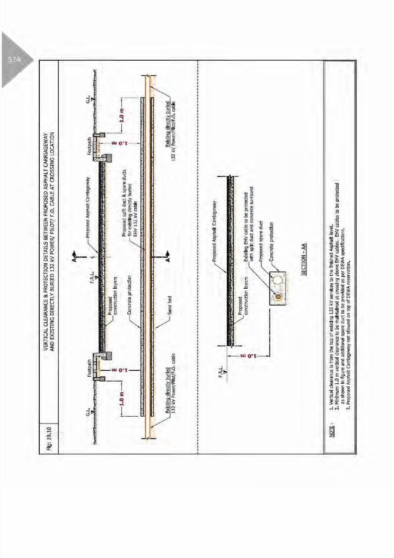
Table 3: Clearance & Protection details for Proposed Asphalt Carriageway and existing
DEWA Electricity EHV services
Electricity EHVExisting Services
HorizontalClearance
Crossing details
RemarksVertical
Clearance
Crossing
Position
Crossing
Method
Standard
Protection
Oil Filled Cable(O.F) A - R
Power/Pilot/
F.O Cable
(Directly Buried)
1.0 m A - R
1.0 m A - R
Duct Bank 1.0 m A - R
Joint Bay/
Transition Joint
NA - - -
15.0 m
B - R
16.5 m
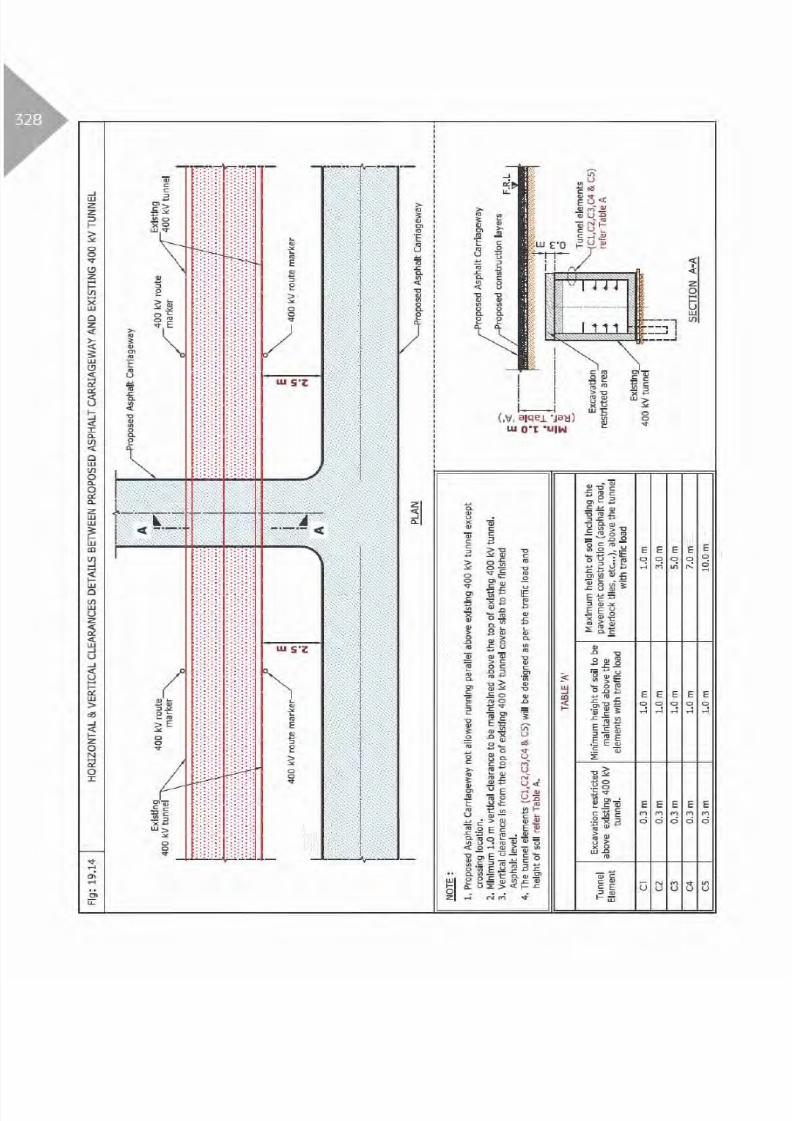
Tunnel 1.0 m A - R
Clearance & Protection details for access and working under Existing EHV-OHL
5.0 m
B - R
7.5 m
Table Abbreviation
A - Above existing DEWA services. OC - Open Cut Method.
B - Below existing DEWA services. R - Required Protection.
A/B - Above or Below existing DEWA services. NR - Not required.
NDCM - Non Disruptive Crossing Method. NA - Not allowed.

8/15/2019 Dewa Latest Reg 2014
http://slidepdf.com/reader/full/dewa-latest-reg-2014 343/817
8/15/2019 Dewa Latest Reg 2014
http://slidepdf.com/reader/full/dewa-latest-reg-2014 344/817

8/15/2019 Dewa Latest Reg 2014
http://slidepdf.com/reader/full/dewa-latest-reg-2014 345/817

8/15/2019 Dewa Latest Reg 2014
http://slidepdf.com/reader/full/dewa-latest-reg-2014 346/817

8/15/2019 Dewa Latest Reg 2014
http://slidepdf.com/reader/full/dewa-latest-reg-2014 347/817
8/15/2019 Dewa Latest Reg 2014
http://slidepdf.com/reader/full/dewa-latest-reg-2014 348/817

8/15/2019 Dewa Latest Reg 2014
http://slidepdf.com/reader/full/dewa-latest-reg-2014 349/817

8/15/2019 Dewa Latest Reg 2014
http://slidepdf.com/reader/full/dewa-latest-reg-2014 350/817

8/15/2019 Dewa Latest Reg 2014
http://slidepdf.com/reader/full/dewa-latest-reg-2014 351/817

8/15/2019 Dewa Latest Reg 2014
http://slidepdf.com/reader/full/dewa-latest-reg-2014 352/817

8/15/2019 Dewa Latest Reg 2014
http://slidepdf.com/reader/full/dewa-latest-reg-2014 353/817

8/15/2019 Dewa Latest Reg 2014
http://slidepdf.com/reader/full/dewa-latest-reg-2014 354/817

8/15/2019 Dewa Latest Reg 2014
http://slidepdf.com/reader/full/dewa-latest-reg-2014 355/817

8/15/2019 Dewa Latest Reg 2014
http://slidepdf.com/reader/full/dewa-latest-reg-2014 356/817
8/15/2019 Dewa Latest Reg 2014
http://slidepdf.com/reader/full/dewa-latest-reg-2014 357/817

8/15/2019 Dewa Latest Reg 2014
http://slidepdf.com/reader/full/dewa-latest-reg-2014 358/817
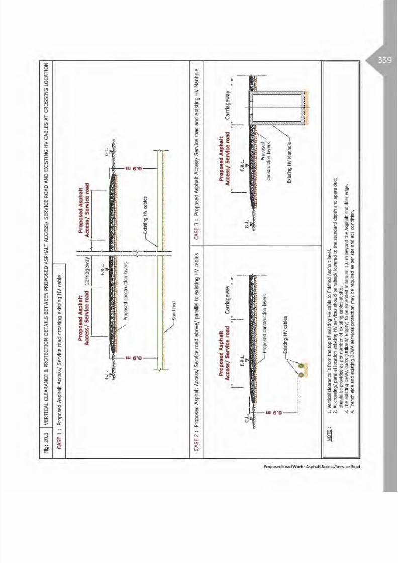
8/15/2019 Dewa Latest Reg 2014
http://slidepdf.com/reader/full/dewa-latest-reg-2014 359/817

8/15/2019 Dewa Latest Reg 2014
http://slidepdf.com/reader/full/dewa-latest-reg-2014 360/817

8/15/2019 Dewa Latest Reg 2014
http://slidepdf.com/reader/full/dewa-latest-reg-2014 361/817

8/15/2019 Dewa Latest Reg 2014
http://slidepdf.com/reader/full/dewa-latest-reg-2014 362/817

8/15/2019 Dewa Latest Reg 2014
http://slidepdf.com/reader/full/dewa-latest-reg-2014 363/817

8/15/2019 Dewa Latest Reg 2014
http://slidepdf.com/reader/full/dewa-latest-reg-2014 364/817
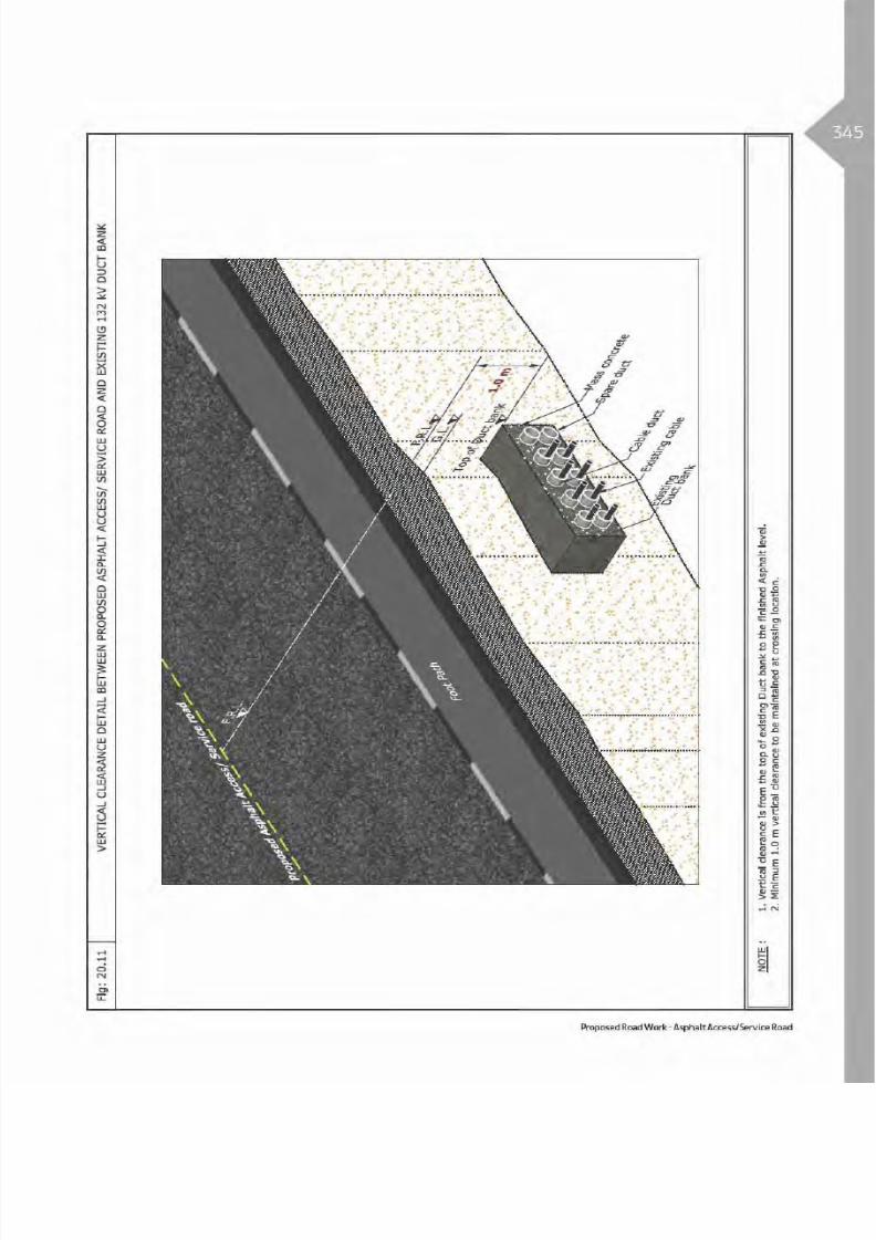
8/15/2019 Dewa Latest Reg 2014
http://slidepdf.com/reader/full/dewa-latest-reg-2014 365/817

8/15/2019 Dewa Latest Reg 2014
http://slidepdf.com/reader/full/dewa-latest-reg-2014 366/817

8/15/2019 Dewa Latest Reg 2014
http://slidepdf.com/reader/full/dewa-latest-reg-2014 367/817

8/15/2019 Dewa Latest Reg 2014
http://slidepdf.com/reader/full/dewa-latest-reg-2014 368/817

8/15/2019 Dewa Latest Reg 2014
http://slidepdf.com/reader/full/dewa-latest-reg-2014 369/817
Table 4: Clearance & Protection details for Proposed Asphalt Access/Service Road and existing
DEWA Gas/Fuel services
Gas/Fuel Existing
Services
Horizontal
Clearance
Crossing DetailsRemarksVertical
Clearance
Crossing
Position
Crossing
Method
Standard
Protection
Existing Fence 8.0 m NA - - R
Gas/Fuel pipeline
(All diameter)10.0 m 3.0 m A - R
Table Abbreviation
A - Above existing DEWA services. OC - Open Cut Method.
B - Below existing DEWA services. R - Required Protection.
A/B - Above or Below existing DEWA services. NR - Not required.
NDCM - Non Disruptive Crossing Method. NA - Not allowed.
Proposed Road Work - Asphalt Access/Service Road

8/15/2019 Dewa Latest Reg 2014
http://slidepdf.com/reader/full/dewa-latest-reg-2014 370/817
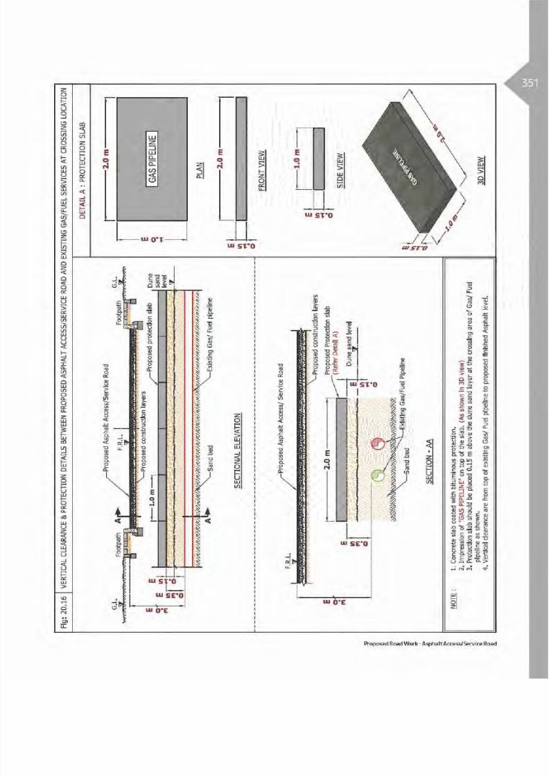
8/15/2019 Dewa Latest Reg 2014
http://slidepdf.com/reader/full/dewa-latest-reg-2014 371/817

8/15/2019 Dewa Latest Reg 2014
http://slidepdf.com/reader/full/dewa-latest-reg-2014 372/817
Asphalt Parking
21.1 Introduction
Asphalted parking lot is the area, remote from theroad designated for the parking of vehicles. The roadmay contain Parking lanes which are the areas on thepavement, perpendicular, inclined or parallel to butoutside the travelling way. Each parking lane containsseveral parking bays in which the area are marked outfor different sizes of vehicle parking.
Asphalted Parking can be in one or both sides ofthe road within the Right Of Way, therefore duringconstruction activities it is required to protect DEWAexisting assets as per specified standards.

8/15/2019 Dewa Latest Reg 2014
http://slidepdf.com/reader/full/dewa-latest-reg-2014 373/817

8/15/2019 Dewa Latest Reg 2014
http://slidepdf.com/reader/full/dewa-latest-reg-2014 374/817

8/15/2019 Dewa Latest Reg 2014
http://slidepdf.com/reader/full/dewa-latest-reg-2014 375/817
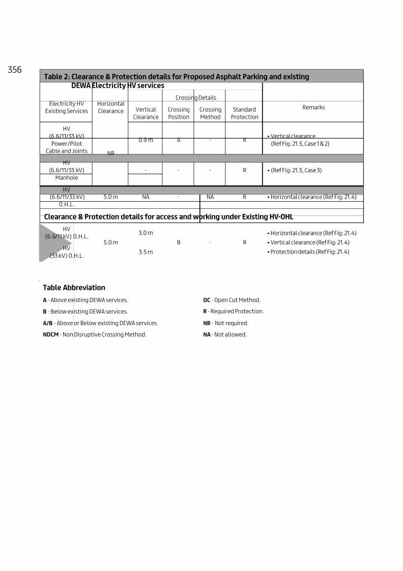
8/15/2019 Dewa Latest Reg 2014
http://slidepdf.com/reader/full/dewa-latest-reg-2014 376/817
56Table 2: Clearance & Protection details for Proposed Asphalt Parking and existing
DEWA Electricity HV services
Electricity HV
Existing Services
Horizontal
Clearance
Crossing DetailsRemarksVertical
Clearance
Crossing
Position
Crossing
Method
Standard
Protection
HV
(6.6/11/33 kV)
Power/Pilot
Cable and Joints NR
0.9 m A - R
HV
(6.6/11/33 kV)
Manhole
- - - R
HV
(6.6/11/33 kV)
O.H.L.
5.0 m NA - NA R
Clearance & Protection details for access and working under Existing HV-OHL
HV
(6.6/11 kV) O.H.L.5.0 m
3.0 m
B - R
HV
(33 kV) O.H.L.3.5 m
Table Abbreviation
A - Above existing DEWA services. OC - Open Cut Method.
B - Below existing DEWA services. R - Required Protection.
A/B - Above or Below existing DEWA services. NR - Not required.
NDCM - Non Disruptive Crossing Method. NA - Not allowed.

8/15/2019 Dewa Latest Reg 2014
http://slidepdf.com/reader/full/dewa-latest-reg-2014 377/817

8/15/2019 Dewa Latest Reg 2014
http://slidepdf.com/reader/full/dewa-latest-reg-2014 378/817

8/15/2019 Dewa Latest Reg 2014
http://slidepdf.com/reader/full/dewa-latest-reg-2014 379/817

8/15/2019 Dewa Latest Reg 2014
http://slidepdf.com/reader/full/dewa-latest-reg-2014 380/817

8/15/2019 Dewa Latest Reg 2014
http://slidepdf.com/reader/full/dewa-latest-reg-2014 381/817

8/15/2019 Dewa Latest Reg 2014
http://slidepdf.com/reader/full/dewa-latest-reg-2014 382/817
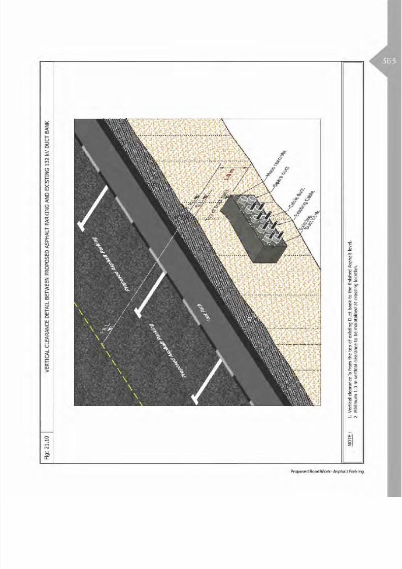
8/15/2019 Dewa Latest Reg 2014
http://slidepdf.com/reader/full/dewa-latest-reg-2014 383/817

8/15/2019 Dewa Latest Reg 2014
http://slidepdf.com/reader/full/dewa-latest-reg-2014 384/817

8/15/2019 Dewa Latest Reg 2014
http://slidepdf.com/reader/full/dewa-latest-reg-2014 385/817

8/15/2019 Dewa Latest Reg 2014
http://slidepdf.com/reader/full/dewa-latest-reg-2014 386/817

8/15/2019 Dewa Latest Reg 2014
http://slidepdf.com/reader/full/dewa-latest-reg-2014 387/817
367Table 4: Clearance & Protection details for Proposed Asphalt Parking and existing
DEWA Gas/Fuel services
Gas/Fuel Existing
Services
Horizontal
Clearance
Crossing DetailsRemarksVertical
Clearance
Crossing
Position
Crossing
Method
Standard
Protection
Existing Fence 8.0 m NA - - R
Gas/Fuel pipeline
(All diameter)10.0 m 3.0 m A - R
Table Abbreviation
A - Above existing DEWA services. OC - Open Cut Method.
B - Below existing DEWA services. R - Required Protection.
A/B - Above or Below existing DEWA services. NR - Not required.
NDCM - Non Disruptive Crossing Method. NA - Not allowed.
Proposed Road Work - Asphalt Parking

8/15/2019 Dewa Latest Reg 2014
http://slidepdf.com/reader/full/dewa-latest-reg-2014 388/817

8/15/2019 Dewa Latest Reg 2014
http://slidepdf.com/reader/full/dewa-latest-reg-2014 389/817

8/15/2019 Dewa Latest Reg 2014
http://slidepdf.com/reader/full/dewa-latest-reg-2014 390/817

8/15/2019 Dewa Latest Reg 2014
http://slidepdf.com/reader/full/dewa-latest-reg-2014 391/817
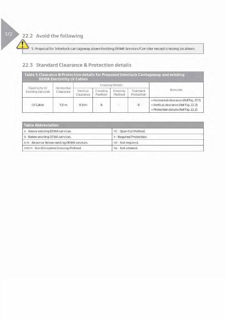
8/15/2019 Dewa Latest Reg 2014
http://slidepdf.com/reader/full/dewa-latest-reg-2014 392/817

8/15/2019 Dewa Latest Reg 2014
http://slidepdf.com/reader/full/dewa-latest-reg-2014 393/817

8/15/2019 Dewa Latest Reg 2014
http://slidepdf.com/reader/full/dewa-latest-reg-2014 394/817

8/15/2019 Dewa Latest Reg 2014
http://slidepdf.com/reader/full/dewa-latest-reg-2014 395/817

8/15/2019 Dewa Latest Reg 2014
http://slidepdf.com/reader/full/dewa-latest-reg-2014 396/817

8/15/2019 Dewa Latest Reg 2014
http://slidepdf.com/reader/full/dewa-latest-reg-2014 397/817
377
Table Abbreviation
A - Above existing DEWA services. OC - Open Cut Method.
B - Below existing DEWA services. R - Required Protection.
A/B - Above or Below existing DEWA services. NR - Not required.
NDCM - Non Disruptive Crossing Method. NA - Not allowed.
Table 3: Clearance & Protection details for Proposed Interlock Carriageway and existing
DEWA Electricity EHV services
Electricity EHV
Existing Services
Horizontal
Clearance
Crossing DetailsRemarksVertical
Clearance
Crossing
Position
Crossing
Method
Standard
Protection
Oil Filled
Cable(O.F)
A - R
Power/Pilot/
F.O Cable
(Directly Buried)
1.0 m A - R
Trough
1.0 m A - R
Duct Bank 1.0 m A - R
Joint Bay/
Transition Joint
NA - - -
O.H.L 15.0 m
B - R
O.H.L 16.5 m
Tunnel 1.0 m A - R
Clearance & Protection details for access and working under Existing EHV-OHL
O.H.L
5.0 m
B - R
O.H.L
7.5 m
Proposed Road Work - Interlock Carriageway

8/15/2019 Dewa Latest Reg 2014
http://slidepdf.com/reader/full/dewa-latest-reg-2014 398/817

8/15/2019 Dewa Latest Reg 2014
http://slidepdf.com/reader/full/dewa-latest-reg-2014 399/817

8/15/2019 Dewa Latest Reg 2014
http://slidepdf.com/reader/full/dewa-latest-reg-2014 400/817

8/15/2019 Dewa Latest Reg 2014
http://slidepdf.com/reader/full/dewa-latest-reg-2014 401/817

8/15/2019 Dewa Latest Reg 2014
http://slidepdf.com/reader/full/dewa-latest-reg-2014 402/817

8/15/2019 Dewa Latest Reg 2014
http://slidepdf.com/reader/full/dewa-latest-reg-2014 403/817

8/15/2019 Dewa Latest Reg 2014
http://slidepdf.com/reader/full/dewa-latest-reg-2014 404/817
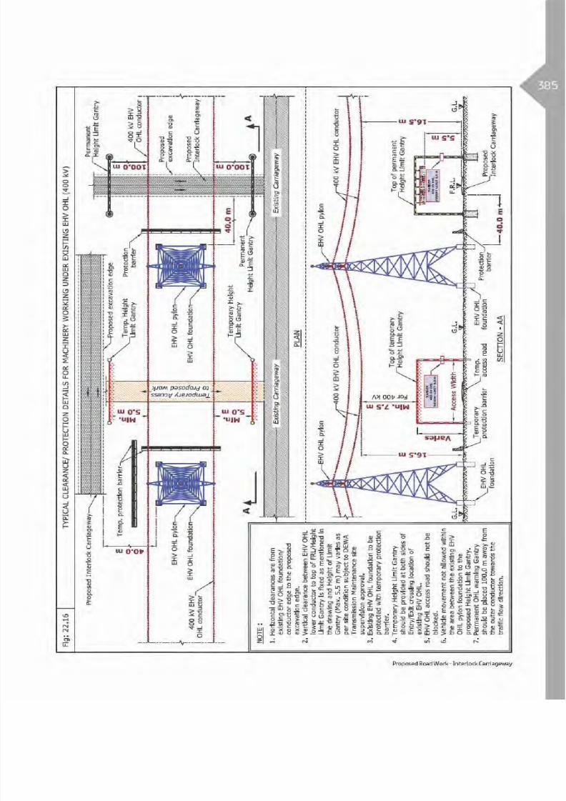
8/15/2019 Dewa Latest Reg 2014
http://slidepdf.com/reader/full/dewa-latest-reg-2014 405/817

8/15/2019 Dewa Latest Reg 2014
http://slidepdf.com/reader/full/dewa-latest-reg-2014 406/817

8/15/2019 Dewa Latest Reg 2014
http://slidepdf.com/reader/full/dewa-latest-reg-2014 407/817
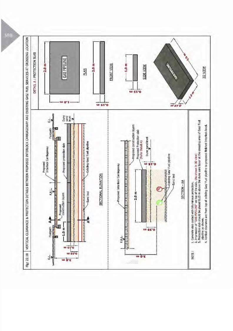
8/15/2019 Dewa Latest Reg 2014
http://slidepdf.com/reader/full/dewa-latest-reg-2014 408/817

8/15/2019 Dewa Latest Reg 2014
http://slidepdf.com/reader/full/dewa-latest-reg-2014 409/817

8/15/2019 Dewa Latest Reg 2014
http://slidepdf.com/reader/full/dewa-latest-reg-2014 410/817

8/15/2019 Dewa Latest Reg 2014
http://slidepdf.com/reader/full/dewa-latest-reg-2014 411/817

8/15/2019 Dewa Latest Reg 2014
http://slidepdf.com/reader/full/dewa-latest-reg-2014 412/817

8/15/2019 Dewa Latest Reg 2014
http://slidepdf.com/reader/full/dewa-latest-reg-2014 413/817
393Table 2: Clearance & Protection details for Proposed Interlock Access /Service Road and existing
DEWA Electricity HV services
Electricity HV
Existing Services
Horizontal
Clearance
Crossing DetailsRemarksVertical
Clearance
Crossing
Position
Crossing
Method
Standard
Protection
HV
(6.6/11/33 kV)
Power/Pilot
Cable and Joints.NR
0.9 m A - R
HV
(6.6/11/33 kV)
Manhole.
- - - R
HV
(6.6/11/33 kV)
O.H.L.
5.0 m NA - - R
Clearance & Protection details for access and working under Existing HV-OHL
HV
(6.6/11 kV) O.H.L.5.0 m
3.0 m
B - R
HV
(33 kV) O.H.L.3.5 m
Table Abbreviation
A - Above existing DEWA services. OC - Open Cut Method.
B - Below existing DEWA services. R - Required Protection.
A/B - Above or Below existing DEWA services. NR - Not required.
NDCM - Non Disruptive Crossing Method. NA - Not allowed.
Proposed Road Work - Interlock Access/Service Road
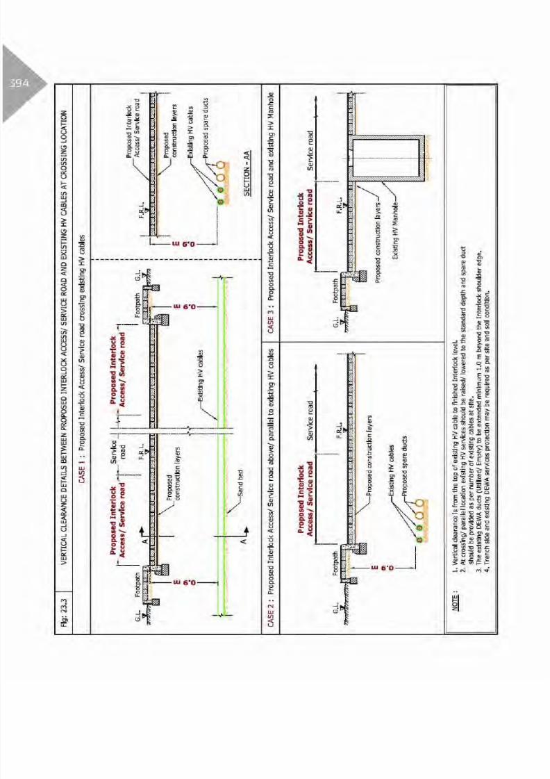
8/15/2019 Dewa Latest Reg 2014
http://slidepdf.com/reader/full/dewa-latest-reg-2014 414/817

8/15/2019 Dewa Latest Reg 2014
http://slidepdf.com/reader/full/dewa-latest-reg-2014 415/817

8/15/2019 Dewa Latest Reg 2014
http://slidepdf.com/reader/full/dewa-latest-reg-2014 416/817
96
Table Abbreviation
A - Above existing DEWA services. OC - Open Cut Method.
B - Below existing DEWA services. R - Required Protection.
A/B - Above or Below existing DEWA services. NR - Not required.
NDCM - Non Disruptive Crossing Method. NA - Not allowed.
Table 3: Clearance & Protection details for Proposed Interlock Access /Service Road and existing
DEWA Electricity EHV services
ElectricityEHV Existing
Services
Horizontal
Clearance
Crossing DetailsRemarksVertical
Clearance
Crossing
Position
Crossing
Method
Standard
Protection
Oil Filled Cable
(O.F)
A - R
Power/Pilot/
F.O Cable
(Directly Buried)
NR 1.0 m A - R
Trough
NR 1.0 m A - R
Duct BankNR 1.0 m A - R
Joint Bay/
Transition Joint
NA - - -
O.H.L 15.0 m
B - R
O.H.L 16.5 m
Tunnel 1.0 m A - R
Clearance & Protection details for access and working under Existing EHV-OHL
O.H.L
5.0 m
B - R
O.H.L7.5 m

8/15/2019 Dewa Latest Reg 2014
http://slidepdf.com/reader/full/dewa-latest-reg-2014 417/817

8/15/2019 Dewa Latest Reg 2014
http://slidepdf.com/reader/full/dewa-latest-reg-2014 418/817

8/15/2019 Dewa Latest Reg 2014
http://slidepdf.com/reader/full/dewa-latest-reg-2014 419/817
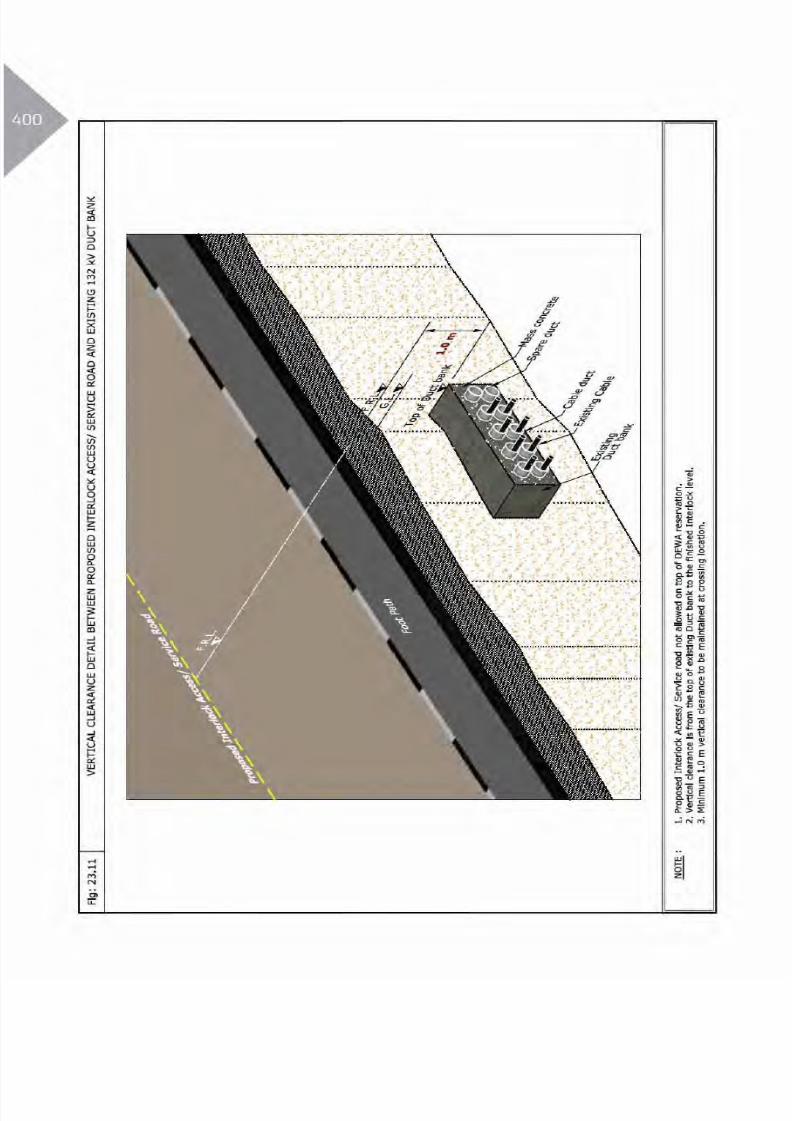
8/15/2019 Dewa Latest Reg 2014
http://slidepdf.com/reader/full/dewa-latest-reg-2014 420/817

8/15/2019 Dewa Latest Reg 2014
http://slidepdf.com/reader/full/dewa-latest-reg-2014 421/817

8/15/2019 Dewa Latest Reg 2014
http://slidepdf.com/reader/full/dewa-latest-reg-2014 422/817

8/15/2019 Dewa Latest Reg 2014
http://slidepdf.com/reader/full/dewa-latest-reg-2014 423/817

8/15/2019 Dewa Latest Reg 2014
http://slidepdf.com/reader/full/dewa-latest-reg-2014 424/817

8/15/2019 Dewa Latest Reg 2014
http://slidepdf.com/reader/full/dewa-latest-reg-2014 425/817

8/15/2019 Dewa Latest Reg 2014
http://slidepdf.com/reader/full/dewa-latest-reg-2014 426/817

8/15/2019 Dewa Latest Reg 2014
http://slidepdf.com/reader/full/dewa-latest-reg-2014 427/817

8/15/2019 Dewa Latest Reg 2014
http://slidepdf.com/reader/full/dewa-latest-reg-2014 428/817

8/15/2019 Dewa Latest Reg 2014
http://slidepdf.com/reader/full/dewa-latest-reg-2014 429/817
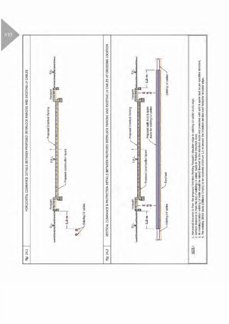
8/15/2019 Dewa Latest Reg 2014
http://slidepdf.com/reader/full/dewa-latest-reg-2014 430/817

8/15/2019 Dewa Latest Reg 2014
http://slidepdf.com/reader/full/dewa-latest-reg-2014 431/817
Table 2: Clearance & Protection details for Proposed Interlock Parking and existing DEWA
Electricity HV services
Electricity HV
Existing Services
Horizontal
Clearance
Crossing DetailsRemarksVertical
Clearance
Crossing
Position
Crossing
Method
Standard
Protection
HV
(6.6/11/33 kV)
Power/Pilot
Cable and Joints NR
0.9 m A - R
HV
(6.6/11/33 kV)
Manhole
- - - R
HV
(6.6/11/33 kV)
O.H.L.
5.0 m NA - - R
Clearance & Protection details for access and working under Existing HV-OHL
HV
(6.6/11 kV) O.H.L.5.0 m
3.0 m
B - R
HV
(33 kV) O.H.L.3.5 m
Table Abbreviation
A - Above existing DEWA services. OC - Open Cut Method.
B - Below existing DEWA services. R - Required Protection.
A/B - Above or Below existing DEWA services. NR - Not required.
NDCM - Non Disruptive Crossing Method. NA - Not allowed.
Proposed Road Work - Interlock Parking

8/15/2019 Dewa Latest Reg 2014
http://slidepdf.com/reader/full/dewa-latest-reg-2014 432/817

8/15/2019 Dewa Latest Reg 2014
http://slidepdf.com/reader/full/dewa-latest-reg-2014 433/817

8/15/2019 Dewa Latest Reg 2014
http://slidepdf.com/reader/full/dewa-latest-reg-2014 434/817
Table Abbreviation
A - Above existing DEWA services. OC - Open Cut Method.
B - Below existing DEWA services. R - Required Protection.
A/B - Above or Below existing DEWA services. NR - Not required.
NDCM - Non Disruptive Crossing Method. NA - Not allowed.
Table 3: Clearance & Protection details for Proposed Interlock Parking and existing DEWA
Electricity EHV services
Electricity EHV
Existing Services
Horizontal
Clearance
Crossing DetailsRemarksVertical
Clearance
Crossing
Position
Crossing
Method
Standard
Protection
Oil Filled
Cable (O.F)
A - R
Power/Pilot/
F.O Cable
(Directly Buried)
NR 1.0 m A - R
TroughNR 1.0 m A - R
Duct BankNR 1.0 m A - R
Joint Bay/
Transition Joint
NA - - -
O.H.L 15.0 m
B - R
O.H.L 16.5 m
Tunnel 1.0 m A - R
Clearance & Protection details for access and working under Existing EHV-OHL
O.H.L
5.0 m
B - R
O.H.L7.5 m

8/15/2019 Dewa Latest Reg 2014
http://slidepdf.com/reader/full/dewa-latest-reg-2014 435/817

8/15/2019 Dewa Latest Reg 2014
http://slidepdf.com/reader/full/dewa-latest-reg-2014 436/817

8/15/2019 Dewa Latest Reg 2014
http://slidepdf.com/reader/full/dewa-latest-reg-2014 437/817

8/15/2019 Dewa Latest Reg 2014
http://slidepdf.com/reader/full/dewa-latest-reg-2014 438/817

8/15/2019 Dewa Latest Reg 2014
http://slidepdf.com/reader/full/dewa-latest-reg-2014 439/817

8/15/2019 Dewa Latest Reg 2014
http://slidepdf.com/reader/full/dewa-latest-reg-2014 440/817

8/15/2019 Dewa Latest Reg 2014
http://slidepdf.com/reader/full/dewa-latest-reg-2014 441/817
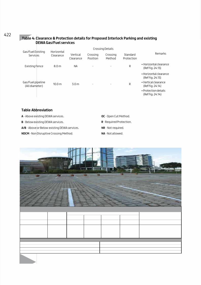
8/15/2019 Dewa Latest Reg 2014
http://slidepdf.com/reader/full/dewa-latest-reg-2014 442/817
Table 4: Clearance & Protection details for Proposed Interlock Parking and existing
DEWA Gas/Fuel services
Gas/Fuel Existing
Services
Horizontal
Clearance
Crossing DetailsRemarksVertical
Clearance
Crossing
Position
Crossing
Method
Standard
Protection
Existing Fence 8.0 m NA - - R
Gas/Fuel pipeline
(All diameter)10.0 m 3.0 m - - R
Table Abbreviation
A - Above existing DEWA services. OC - Open Cut Method.
B - Below existing DEWA services. R - Required Protection.
A/B - Above or Below existing DEWA services. NR - Not required.
NDCM - Non Disruptive Crossing Method. NA - Not allowed.

8/15/2019 Dewa Latest Reg 2014
http://slidepdf.com/reader/full/dewa-latest-reg-2014 443/817

8/15/2019 Dewa Latest Reg 2014
http://slidepdf.com/reader/full/dewa-latest-reg-2014 444/817

8/15/2019 Dewa Latest Reg 2014
http://slidepdf.com/reader/full/dewa-latest-reg-2014 445/817
25.1 IntroductionThe purpose of bridge/interchange/flyover/railwayoverpass is to cross over existing water ways, roads,railway tracks etc., to enable free traffic to flow throughthe junctions without direct crossing or congestion.
These structures consist of infrastructure andsuperstructure elements such as concrete foundation,
piles, piers and ramps etc., the infrastructure/superstructure are constructed within Right Of Waytherefore; it is required to protect DEWA existing assetsas per specified standards.
(Bridges/Interchanges/Railway/Ramps/Flyover/Roundabout)
Proposed Road Work

8/15/2019 Dewa Latest Reg 2014
http://slidepdf.com/reader/full/dewa-latest-reg-2014 446/817

8/15/2019 Dewa Latest Reg 2014
http://slidepdf.com/reader/full/dewa-latest-reg-2014 447/817

8/15/2019 Dewa Latest Reg 2014
http://slidepdf.com/reader/full/dewa-latest-reg-2014 448/817

8/15/2019 Dewa Latest Reg 2014
http://slidepdf.com/reader/full/dewa-latest-reg-2014 449/817

8/15/2019 Dewa Latest Reg 2014
http://slidepdf.com/reader/full/dewa-latest-reg-2014 450/817

8/15/2019 Dewa Latest Reg 2014
http://slidepdf.com/reader/full/dewa-latest-reg-2014 451/817

8/15/2019 Dewa Latest Reg 2014
http://slidepdf.com/reader/full/dewa-latest-reg-2014 452/817

8/15/2019 Dewa Latest Reg 2014
http://slidepdf.com/reader/full/dewa-latest-reg-2014 453/817

8/15/2019 Dewa Latest Reg 2014
http://slidepdf.com/reader/full/dewa-latest-reg-2014 454/817
Table Abbreviation
A - Above existing DEWA services. OC - Open Cut Method.
B - Below existing DEWA services. R - Required Protection.
A/B - Above or Below existing DEWA services. NR - Not required.
NDCM - Non Disruptive Crossing Method. NA - Not allowed.
Table 3: Clearance & Protection details for proposed work and existing DEWA Electricity
EHV services
Electricity EHV
Existing Services
Horizontal
Clearance
Crossing DetailsRemarksVertical
Clearance
Crossing
Position
Crossing
Method
Standard
Protection
Oil Filled
Cable(O.F)
5.5 m A - R
Power/Pilot/
F.O Cable
(Directly Buried)
5.5 m A - R
Trough 5.5 m A - R
Duct Bank NR A - R
Joint Bay/
Transition Joint
5.5 m A - R
TunnelTo be studied on case by case basis.
10.0 m 15.0 m B - R
16.0 m 16.5 m B - R
Clearance & Protection details for access and working under Existing EHV-OHL
5.0 m
B - R
7.5 m

8/15/2019 Dewa Latest Reg 2014
http://slidepdf.com/reader/full/dewa-latest-reg-2014 455/817

8/15/2019 Dewa Latest Reg 2014
http://slidepdf.com/reader/full/dewa-latest-reg-2014 456/817

8/15/2019 Dewa Latest Reg 2014
http://slidepdf.com/reader/full/dewa-latest-reg-2014 457/817

8/15/2019 Dewa Latest Reg 2014
http://slidepdf.com/reader/full/dewa-latest-reg-2014 458/817

8/15/2019 Dewa Latest Reg 2014
http://slidepdf.com/reader/full/dewa-latest-reg-2014 459/817

8/15/2019 Dewa Latest Reg 2014
http://slidepdf.com/reader/full/dewa-latest-reg-2014 460/817

8/15/2019 Dewa Latest Reg 2014
http://slidepdf.com/reader/full/dewa-latest-reg-2014 461/817
Table 4: Clearance & Protection details for proposed work and existing DEWA Gas/Fuel services
Gas/Fuel ExistingServices
HorizontalClearance
Crossing Details
RemarksVertical
Clearance
Crossing
Position
Crossing
Method
Standard
Protection
Existing Fence 13.0 m NA - - R
Gas/Fuel pipeline
(All diameter)15.0 m NA - - R
Table Abbreviation
A - Above existing DEWA services. OC - Open Cut Method.
B - Below existing DEWA services. R - Required Protection.
A/B - Above or Below existing DEWA services. NR - Not required.
NDCM - Non Disruptive Crossing Method. NA - Not allowed.
Proposed Road Work

8/15/2019 Dewa Latest Reg 2014
http://slidepdf.com/reader/full/dewa-latest-reg-2014 462/817
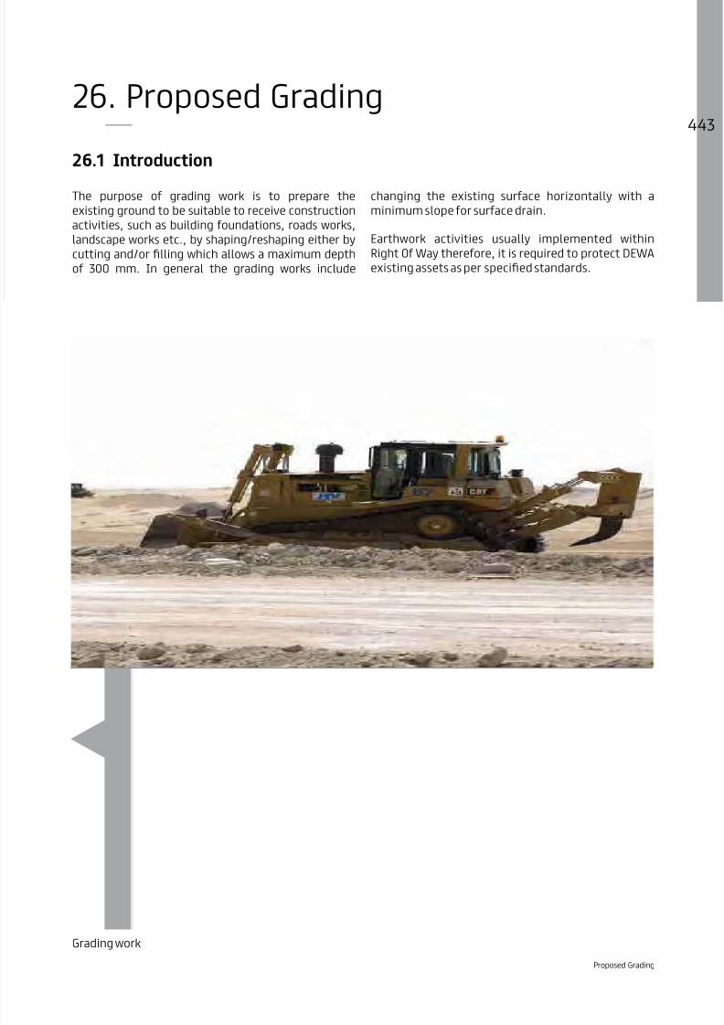
8/15/2019 Dewa Latest Reg 2014
http://slidepdf.com/reader/full/dewa-latest-reg-2014 463/817

8/15/2019 Dewa Latest Reg 2014
http://slidepdf.com/reader/full/dewa-latest-reg-2014 464/817

8/15/2019 Dewa Latest Reg 2014
http://slidepdf.com/reader/full/dewa-latest-reg-2014 465/817
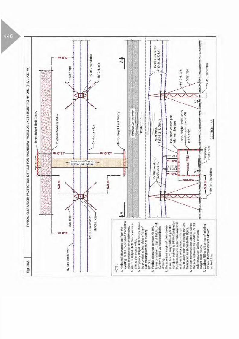
8/15/2019 Dewa Latest Reg 2014
http://slidepdf.com/reader/full/dewa-latest-reg-2014 466/817

8/15/2019 Dewa Latest Reg 2014
http://slidepdf.com/reader/full/dewa-latest-reg-2014 467/817
Table 3: Clearance & Protection details for Proposed Grading works and existing
DEWA Electricity EHV services
Electricity EHV
Existing Services
Horizontal
Clearance
Crossing DetailsRemarksVertical
Clearance
Crossing
Position
Crossing
Method
Standard
Protection
Oil Filled Cable (O.F)NR 0.9 m - - R
Power/Pilot/
F.O Cable
(Directly Buried)
NR 0.9 m - - R
NR 0.9 m - - R
Duct Bank
NR 0.9 m - - R
Joint Bay/Transition
Joint
NA - - - - -
NR
15.0 m- - R
16.5 m
NR 1.0 m - - R
Clearance & Protection details for access and working under Existing EHV-OHL
5.0 m
- - R
7.5 m
Table Abbreviation
A - Above existing DEWA services. OC - Open Cut Method.
B - Below existing DEWA services. R - Required Protection.
A/B - Above or Below existing DEWA services. NR - Not required.
NDCM - Non Disruptive Crossing Method. NA - Not allowed.
Proposed Grading

8/15/2019 Dewa Latest Reg 2014
http://slidepdf.com/reader/full/dewa-latest-reg-2014 468/817

8/15/2019 Dewa Latest Reg 2014
http://slidepdf.com/reader/full/dewa-latest-reg-2014 469/817

8/15/2019 Dewa Latest Reg 2014
http://slidepdf.com/reader/full/dewa-latest-reg-2014 470/817

8/15/2019 Dewa Latest Reg 2014
http://slidepdf.com/reader/full/dewa-latest-reg-2014 471/817
Table 4: Clearance & Protection details for Proposed Grading works and existing
DEWA Gas/Fuel services
Gas/Fuel Existing
Services
Horizontal
Clearance
Crossing DetailsRemarksVertical
Clearance
Crossing
Position
Crossing
Method
Standard
Protection
Existing Fence 8.0 m NA - - R
Gas/Fuel pipeline
(All diameter)10.0 m NA - - R
Table Abbreviation
A - Above existing DEWA services. OC - Open Cut Method.
B - Below existing DEWA services. R - Required Protection.
A/B - Above or Below existing DEWA services. NR - Not required.
NDCM - Non Disruptive Crossing Method. NA - Not allowed.
Proposed Grading

8/15/2019 Dewa Latest Reg 2014
http://slidepdf.com/reader/full/dewa-latest-reg-2014 472/817

8/15/2019 Dewa Latest Reg 2014
http://slidepdf.com/reader/full/dewa-latest-reg-2014 473/817

8/15/2019 Dewa Latest Reg 2014
http://slidepdf.com/reader/full/dewa-latest-reg-2014 474/817
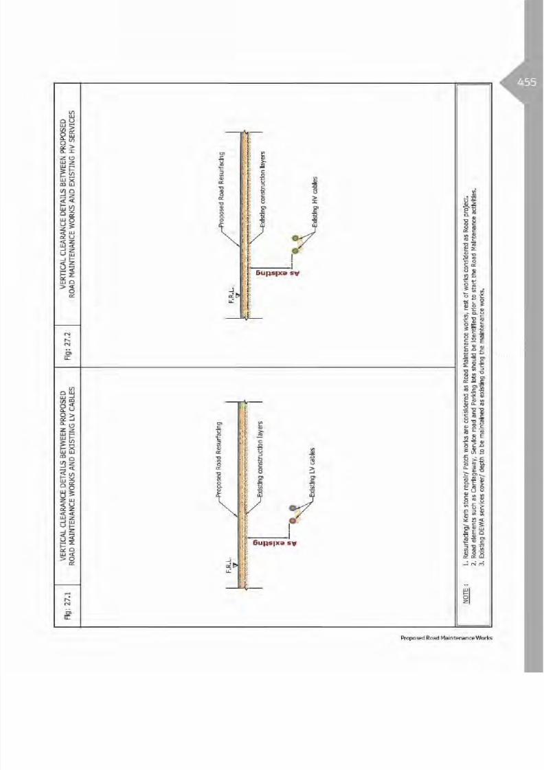
8/15/2019 Dewa Latest Reg 2014
http://slidepdf.com/reader/full/dewa-latest-reg-2014 475/817

8/15/2019 Dewa Latest Reg 2014
http://slidepdf.com/reader/full/dewa-latest-reg-2014 476/817

8/15/2019 Dewa Latest Reg 2014
http://slidepdf.com/reader/full/dewa-latest-reg-2014 477/817
Table 3: Clearance & Protection details for Proposed Road Maintenance -Resurfacing and
existing DEWA Electricity EHV services
Electricity EHV Existing
Services
Horizontal
Clearance
Crossing DetailsRemarksVertical
Clearance
Crossing
Position
Crossing
Method
Standard
Protection
Oil Filled Cable(O.F)NR
As
Existing- - R
Power/Pilot/F.O Cable
(Directly Buried)
NRAs
Existing- - R
NRAs
Existing- - R
Duct Bank NR
As
Existing - - R
Joint Bay/
Transition Joint
NA - - - R -
NA - - - R -
NRAs
Existing- - R
Clearance & Protection details for access and working under Existing EHV-OHL
5.0 m
B - R
7.5 m
Table Abbreviation
A - Above existing DEWA services. OC - Open Cut Method.
B - Below existing DEWA services. R - Required Protection.
A/B - Above or Below existing DEWA services. NR - Not required.
NDCM - Non Disruptive Crossing Method. NA - Not allowed.
Proposed Road Maintenance Works

8/15/2019 Dewa Latest Reg 2014
http://slidepdf.com/reader/full/dewa-latest-reg-2014 478/817

8/15/2019 Dewa Latest Reg 2014
http://slidepdf.com/reader/full/dewa-latest-reg-2014 479/817

8/15/2019 Dewa Latest Reg 2014
http://slidepdf.com/reader/full/dewa-latest-reg-2014 480/817

8/15/2019 Dewa Latest Reg 2014
http://slidepdf.com/reader/full/dewa-latest-reg-2014 481/817

8/15/2019 Dewa Latest Reg 2014
http://slidepdf.com/reader/full/dewa-latest-reg-2014 482/817

8/15/2019 Dewa Latest Reg 2014
http://slidepdf.com/reader/full/dewa-latest-reg-2014 483/817
Extension and protection ofexisting Ducts
28.1 Introduction
Proposed ducts are used to provide a clear pathway forlaying future DEWA ED cables without disturbing theexisting Services/Roads.
During the construction activities of proposed duct(s),extension and/or protection, DEWA existing servicesmust be protected as per DEWA specified standards.
Proposed DEWA Electrical Ducts, Extension and protection of existing Ducts

8/15/2019 Dewa Latest Reg 2014
http://slidepdf.com/reader/full/dewa-latest-reg-2014 484/817

8/15/2019 Dewa Latest Reg 2014
http://slidepdf.com/reader/full/dewa-latest-reg-2014 485/817
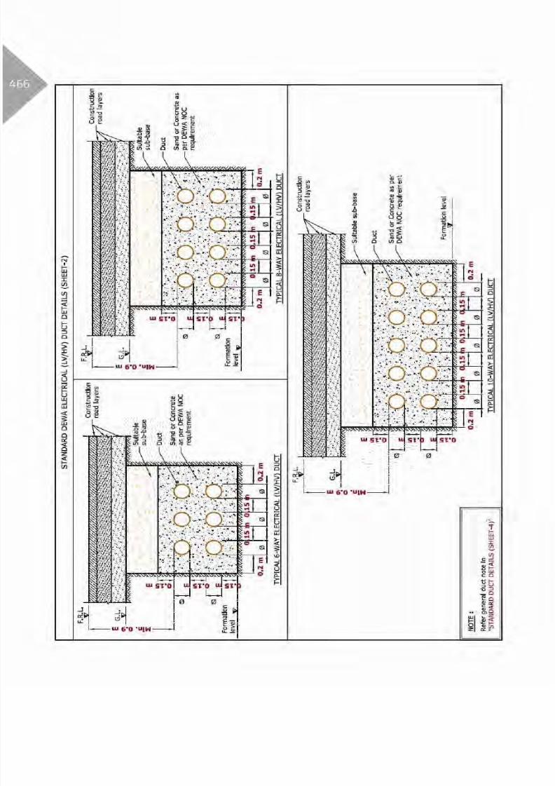
8/15/2019 Dewa Latest Reg 2014
http://slidepdf.com/reader/full/dewa-latest-reg-2014 486/817

8/15/2019 Dewa Latest Reg 2014
http://slidepdf.com/reader/full/dewa-latest-reg-2014 487/817

8/15/2019 Dewa Latest Reg 2014
http://slidepdf.com/reader/full/dewa-latest-reg-2014 488/817

8/15/2019 Dewa Latest Reg 2014
http://slidepdf.com/reader/full/dewa-latest-reg-2014 489/817

8/15/2019 Dewa Latest Reg 2014
http://slidepdf.com/reader/full/dewa-latest-reg-2014 490/817
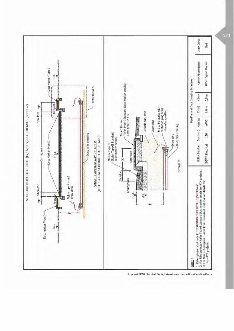
8/15/2019 Dewa Latest Reg 2014
http://slidepdf.com/reader/full/dewa-latest-reg-2014 491/817

8/15/2019 Dewa Latest Reg 2014
http://slidepdf.com/reader/full/dewa-latest-reg-2014 492/817

8/15/2019 Dewa Latest Reg 2014
http://slidepdf.com/reader/full/dewa-latest-reg-2014 493/817

8/15/2019 Dewa Latest Reg 2014
http://slidepdf.com/reader/full/dewa-latest-reg-2014 494/817

8/15/2019 Dewa Latest Reg 2014
http://slidepdf.com/reader/full/dewa-latest-reg-2014 495/817

8/15/2019 Dewa Latest Reg 2014
http://slidepdf.com/reader/full/dewa-latest-reg-2014 496/817

8/15/2019 Dewa Latest Reg 2014
http://slidepdf.com/reader/full/dewa-latest-reg-2014 497/817
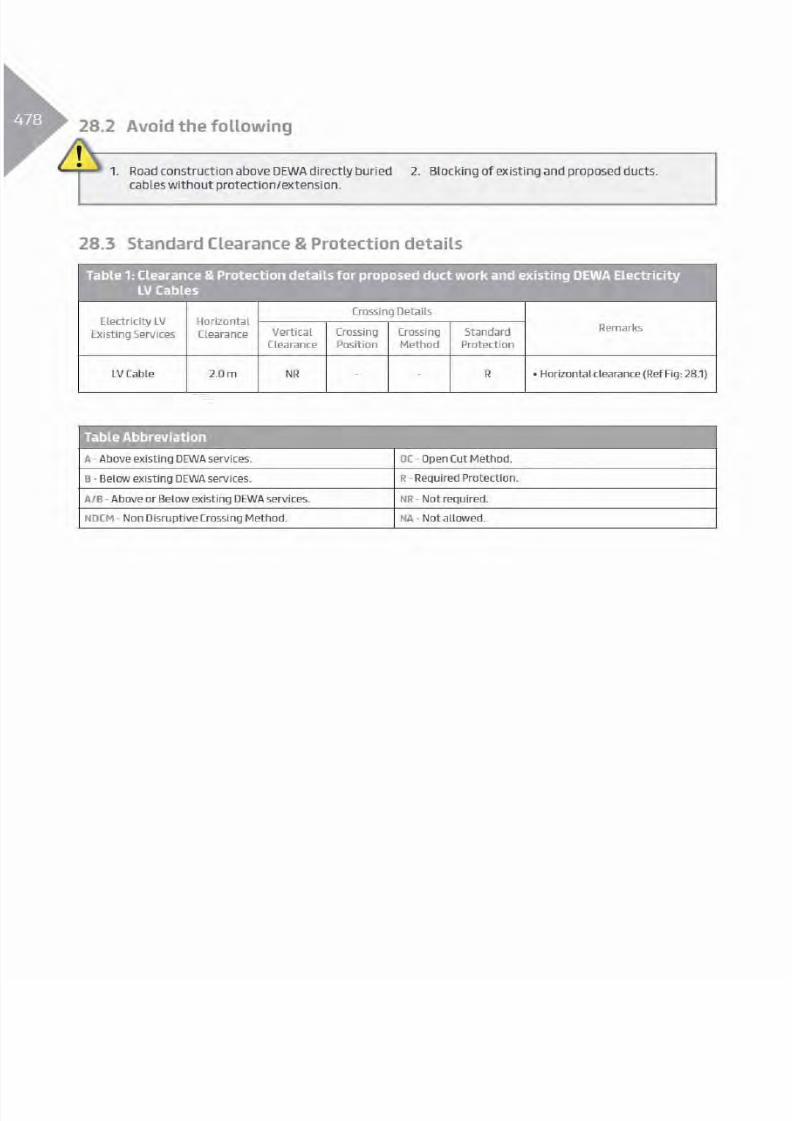
8/15/2019 Dewa Latest Reg 2014
http://slidepdf.com/reader/full/dewa-latest-reg-2014 498/817

8/15/2019 Dewa Latest Reg 2014
http://slidepdf.com/reader/full/dewa-latest-reg-2014 499/817

8/15/2019 Dewa Latest Reg 2014
http://slidepdf.com/reader/full/dewa-latest-reg-2014 500/817
Table 2: Clearance & Protection details for proposed duct work and existing DEWA Electricity
HV services
Electricity HV
Existing Services
Horizontal
Clearance
Crossing DetailsRemarksVertical
Clearance
Crossing
Position
Crossing
Method
Standard
Protection
HV
(6.6/11/33 kV)
Power/Pilot Cable
and Joints
NR - - R
HV
(6.6/11/33 kV)
Manhole
NA - - R
HV
(6.6/11/33 kV)O.H.L.
NR NR - - R -
Table Abbreviation
A - Above existing DEWA services. OC - Open Cut Method.
B - Below existing DEWA services. R - Required Protection.
A/B - Above or Below existing DEWA services. NR - Not required.
NDCM - Non Disruptive Crossing Method. NA - Not allowed.

8/15/2019 Dewa Latest Reg 2014
http://slidepdf.com/reader/full/dewa-latest-reg-2014 501/817

8/15/2019 Dewa Latest Reg 2014
http://slidepdf.com/reader/full/dewa-latest-reg-2014 502/817
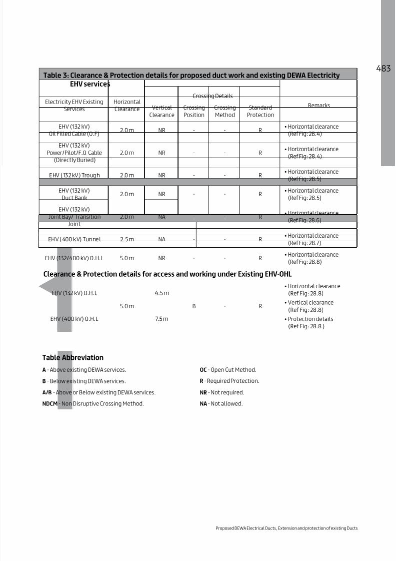
8/15/2019 Dewa Latest Reg 2014
http://slidepdf.com/reader/full/dewa-latest-reg-2014 503/817
Table 3: Clearance & Protection details for proposed duct work and existing DEWA Electricity
EHV services
Electricity EHV Existing
Services
Horizontal
Clearance
Crossing DetailsRemarksVertical
Clearance
Crossing
Position
Crossing
Method
Standard
Protection
Oil Filled Cable (O.F) NR - - R
Power/Pilot/F.O Cable
(Directly Buried)
NR - - R
NR - - R
Duct Bank NR - - R
Joint Bay/ Transition
Joint
NA - - R
NA - - R
5.0 m NR - - R
Clearance & Protection details for access and working under Existing EHV-OHL
5.0 m
B - R
7.5 m
Table Abbreviation
A - Above existing DEWA services. OC - Open Cut Method.
B - Below existing DEWA services. R - Required Protection.
A/B - Above or Below existing DEWA services. NR - Not required.
NDCM - Non Disruptive Crossing Method. NA - Not allowed.
Proposed DEWA Electrical Ducts, Extension and protection of existing Ducts

8/15/2019 Dewa Latest Reg 2014
http://slidepdf.com/reader/full/dewa-latest-reg-2014 504/817

8/15/2019 Dewa Latest Reg 2014
http://slidepdf.com/reader/full/dewa-latest-reg-2014 505/817

8/15/2019 Dewa Latest Reg 2014
http://slidepdf.com/reader/full/dewa-latest-reg-2014 506/817

8/15/2019 Dewa Latest Reg 2014
http://slidepdf.com/reader/full/dewa-latest-reg-2014 507/817

8/15/2019 Dewa Latest Reg 2014
http://slidepdf.com/reader/full/dewa-latest-reg-2014 508/817

8/15/2019 Dewa Latest Reg 2014
http://slidepdf.com/reader/full/dewa-latest-reg-2014 509/817
Table 4: Clearance & Protection details for proposed duct work and existing DEWA
Gas/Fuel services
Gas/Fuel Existing
Services
Horizontal
Clearance
Crossing DetailsRemarksVertical
Clearance
Crossing
Position
Crossing
Method
Standard
Protection
Existing Fence 8.0 m NA - - R
Gas/Fuel pipeline
(All diameter)10.0 m NA - - R
Table Abbreviation
A - Above existing DEWA services. OC - Open Cut Method.
B - Below existing DEWA services. R - Required Protection.
A/B - Above or Below existing DEWA services. NR - Not required.
NDCM - Non Disruptive Crossing Method. NA - Not allowed.
Proposed DEWA Electrical Ducts, Extension and protection of existing Ducts

8/15/2019 Dewa Latest Reg 2014
http://slidepdf.com/reader/full/dewa-latest-reg-2014 510/817

8/15/2019 Dewa Latest Reg 2014
http://slidepdf.com/reader/full/dewa-latest-reg-2014 511/817
29.1 Introduction
The purpose of pedest rian/foot bridges is to providea safe crossing for the pedestrians to cross areaswhere walking could be perilous/impossible suchas carriageways, water ways, etc., from one side tothe other.
This structure consists of foundations, columns, slab,drainage system, elevators, etc. The pedestrian/
foot bridges structures are constructed within RightOf Way therefore during construction activities itis required to protect DEWA existing assets as perspecified standards.
Photo – Pedestrian Bridge
Proposed Pedestrian Bridge

8/15/2019 Dewa Latest Reg 2014
http://slidepdf.com/reader/full/dewa-latest-reg-2014 512/817

8/15/2019 Dewa Latest Reg 2014
http://slidepdf.com/reader/full/dewa-latest-reg-2014 513/817

8/15/2019 Dewa Latest Reg 2014
http://slidepdf.com/reader/full/dewa-latest-reg-2014 514/817

8/15/2019 Dewa Latest Reg 2014
http://slidepdf.com/reader/full/dewa-latest-reg-2014 515/817
Table 3: Clearance & Protection details for proposed Pedestrian Bridge and existing
DEWA Electricity EHV services
Electricity EHV Existing
Services
Horizontal
Clearance
Crossing DetailsRemarksVertical
Clearance
Crossing
Position
Crossing
Method
Standard
Protection
Oil Filled Cable (O.F) NA - - R
Power/Pilot/F.O Cable
(Directly Buried)
NA - - R
NA - - R
Duct Bank NA - - R
Joint Bay/Transition
Joint
NA - - R
NA - - R
15.0 m NA - - R
NA - - R
Table Abbreviation
A - Above existing DEWA services. OC - Open Cut Method.
B - Below existing DEWA services. R - Required Protection.
A/B - Above or Below existing DEWA services. NR - Not required.
NDCM - Non Disruptive Crossing Method. NA - Not allowed.
Proposed Pedestrian Bridge

8/15/2019 Dewa Latest Reg 2014
http://slidepdf.com/reader/full/dewa-latest-reg-2014 516/817

8/15/2019 Dewa Latest Reg 2014
http://slidepdf.com/reader/full/dewa-latest-reg-2014 517/817

8/15/2019 Dewa Latest Reg 2014
http://slidepdf.com/reader/full/dewa-latest-reg-2014 518/817

8/15/2019 Dewa Latest Reg 2014
http://slidepdf.com/reader/full/dewa-latest-reg-2014 519/817

8/15/2019 Dewa Latest Reg 2014
http://slidepdf.com/reader/full/dewa-latest-reg-2014 520/817
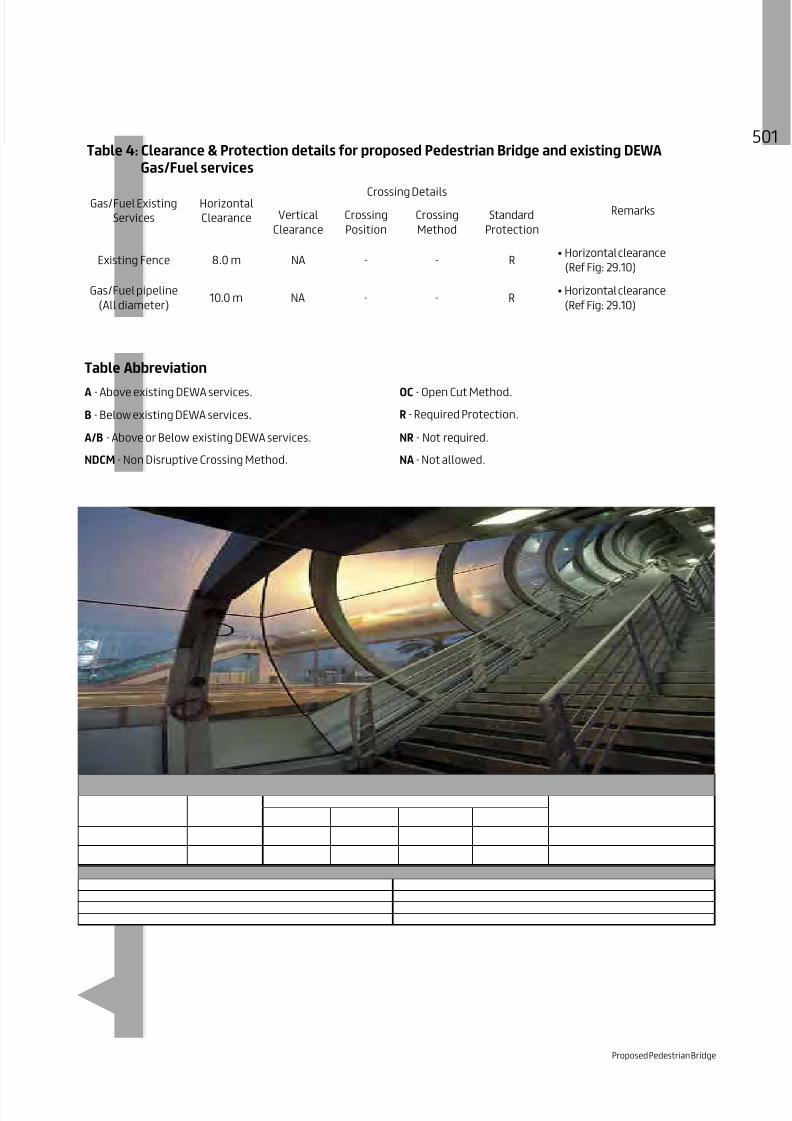
8/15/2019 Dewa Latest Reg 2014
http://slidepdf.com/reader/full/dewa-latest-reg-2014 521/817
501Table 4: Clearance & Protection details for proposed Pedestrian Bridge and existing DEWA
Gas/Fuel services
Gas/Fuel Existing
Services
Horizontal
Clearance
Crossing DetailsRemarksVertical
Clearance
Crossing
Position
Crossing
Method
Standard
Protection
Existing Fence 8.0 m NA - - R
Gas/Fuel pipeline
(All diameter)10.0 m NA - - R
Table Abbreviation
A - Above existing DEWA services. OC - Open Cut Method.
B - Below existing DEWA services. R - Required Protection.
A/B - Above or Below existing DEWA services. NR - Not required.
NDCM - Non Disruptive Crossing Method. NA - Not allowed.
Proposed Pedestrian Bridge

8/15/2019 Dewa Latest Reg 2014
http://slidepdf.com/reader/full/dewa-latest-reg-2014 522/817

8/15/2019 Dewa Latest Reg 2014
http://slidepdf.com/reader/full/dewa-latest-reg-2014 523/817
CHAPTER 3
STRUCTURES

8/15/2019 Dewa Latest Reg 2014
http://slidepdf.com/reader/full/dewa-latest-reg-2014 524/817

8/15/2019 Dewa Latest Reg 2014
http://slidepdf.com/reader/full/dewa-latest-reg-2014 525/817
503
30. Installation of Proposed Bus Shelter/Kiosks
30.1 Introduction
Bus shelters are resting/ waiting areas for passengers.They serve to protect people from adverse weatherconditions. A bus shelter is essentially a kioskconstructed on a concrete foundation with restingseats, lighting, an air conditioning system, signage,bus services time table board, etc.
A bus shelter is constructed within the Right OfWay. Therefore it is important to protect DEWAexisting assets during construction activities as perspecified standards.
Installation of Proposed Bus Shelter/ Kiosks

8/15/2019 Dewa Latest Reg 2014
http://slidepdf.com/reader/full/dewa-latest-reg-2014 526/817

8/15/2019 Dewa Latest Reg 2014
http://slidepdf.com/reader/full/dewa-latest-reg-2014 527/817

8/15/2019 Dewa Latest Reg 2014
http://slidepdf.com/reader/full/dewa-latest-reg-2014 528/817

8/15/2019 Dewa Latest Reg 2014
http://slidepdf.com/reader/full/dewa-latest-reg-2014 529/817
507Table 3: Clearance & Protection details for proposed Bus shelter/Kiosks and existing DEWA
Electricity EHV services
Electricity EHV Existing
Services
Horizontal
Clearance
Crossing DetailsRemarksVertical
Clearance
Crossing
Position
Crossing
Method
Standard
Protection
NA - - R
NA - - R
NA - - R
Duct Bank NA - - R
Joint Bay/ Transition
Joint
NA - - R
NA - - R
15.0 m NA - - -
NA - - -
Table Abbreviation
A - Above existing DEWA services. OC - Open Cut Method.
B - Below existing DEWA services. R - Required Protection.
A/B - Above or Below existing DEWA services. NR - Not required.
NDCM - Non Disruptive Crossing Method. NA - Not allowed.
Installation of Proposed Bus Shelter/ Kiosks

8/15/2019 Dewa Latest Reg 2014
http://slidepdf.com/reader/full/dewa-latest-reg-2014 530/817

8/15/2019 Dewa Latest Reg 2014
http://slidepdf.com/reader/full/dewa-latest-reg-2014 531/817

8/15/2019 Dewa Latest Reg 2014
http://slidepdf.com/reader/full/dewa-latest-reg-2014 532/817

8/15/2019 Dewa Latest Reg 2014
http://slidepdf.com/reader/full/dewa-latest-reg-2014 533/817

8/15/2019 Dewa Latest Reg 2014
http://slidepdf.com/reader/full/dewa-latest-reg-2014 534/817

8/15/2019 Dewa Latest Reg 2014
http://slidepdf.com/reader/full/dewa-latest-reg-2014 535/817
513Table 4: Clearance & Protection details for proposed Bus shelter/Kiosks and existing DEWA
Gas/Fuel services
Services
Horizontal
Clearance
Crossing DetailsRemarksVertical
Clearance
Crossing
Position
Crossing
Method
Standard
Protection
NA - - R
10.0 m NA - - R
Table Abbreviation
A - Above existing DEWA services. OC - Open Cut Method.
B - Below existing DEWA services. R - Required Protection.
A/B - Above or Below existing DEWA services. NR - Not required.
NDCM - Non Disruptive Crossing Method. NA - Not allowed.
Installation of Proposed Bus Shelter/ Kiosks

8/15/2019 Dewa Latest Reg 2014
http://slidepdf.com/reader/full/dewa-latest-reg-2014 536/817

8/15/2019 Dewa Latest Reg 2014
http://slidepdf.com/reader/full/dewa-latest-reg-2014 537/817

8/15/2019 Dewa Latest Reg 2014
http://slidepdf.com/reader/full/dewa-latest-reg-2014 538/817

8/15/2019 Dewa Latest Reg 2014
http://slidepdf.com/reader/full/dewa-latest-reg-2014 539/817

8/15/2019 Dewa Latest Reg 2014
http://slidepdf.com/reader/full/dewa-latest-reg-2014 540/817
Table 2: Clearance & Protection details for proposed Installation of Street light and existing
DEWA Electricity HV services
Electricity HVExisting
Services
Proposed
Street light
Crossing DetailsRemarksHorizontal
Clearance
Vertical
Clearance
Crossing
Position
Crossing
Method
Standard
Protection
HV
Power/Pilot
Cable and
Joints.
0.3 m NA - -
R
Cable 0.3 m B OC
HV
Manhole.
Cable 0.3 m NA - - R
HV
O.H.L.
Street Light
Pole
3.0 m NA - -
R
conductor
NA - -
Cable 5.0 m NR - -
Clearance & Protection details for access and working under Existing HV-OHL
HV
O.H.L.
-
5.0 m
3.0 m
B - R
HV
- 3.5 m
Table Abbreviation
A - Above existing DEWA services. OC - Open Cut Method.
B - Below existing DEWA services. R - Required Protection.
A/B - Above or Below existing DEWA services. NR - Not required.
NDCM - Non Disruptive Crossing Method. NA - Not allowed.

8/15/2019 Dewa Latest Reg 2014
http://slidepdf.com/reader/full/dewa-latest-reg-2014 541/817

8/15/2019 Dewa Latest Reg 2014
http://slidepdf.com/reader/full/dewa-latest-reg-2014 542/817

8/15/2019 Dewa Latest Reg 2014
http://slidepdf.com/reader/full/dewa-latest-reg-2014 543/817

8/15/2019 Dewa Latest Reg 2014
http://slidepdf.com/reader/full/dewa-latest-reg-2014 544/817
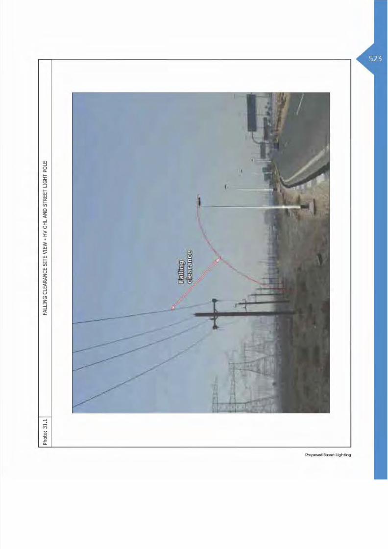
8/15/2019 Dewa Latest Reg 2014
http://slidepdf.com/reader/full/dewa-latest-reg-2014 545/817

8/15/2019 Dewa Latest Reg 2014
http://slidepdf.com/reader/full/dewa-latest-reg-2014 546/817
Table 3: Clearance & Protection details for proposed Installation of Street light and existing
DEWA Electricity EHV services
ElectricityEHV Existing
Services
ProposedStreet light
HorizontalClearance
Crossing details
RemarksVertical
Clearance
Crossing
Position
Crossing
Method
Standard
Protection
1.0 m NA - -
R
Cable 1.0 m 0.5 m B OC
Power/
Pilot/
1.0 m NA - -
R
Cable 1.0 m 0.5 m B OC
Trough
1.0 m NA - -
R
Cable 0.5 m 0.5 m B OC
Duct Bank
1.0 m NA - -
R
Cable 0.5 m 0.5 m B OC
Joint Bay/
Transition
Joint
1.0 m NA - -
R
Cable 0.5 m NA - -
O.H.L
Street light
Pole5.0 m NA - -
R
Cable 5.0 m NR B OC
EHV
O.H.L
Street light
Pole NA - -
R
Cable 5.0 m NR B OC

8/15/2019 Dewa Latest Reg 2014
http://slidepdf.com/reader/full/dewa-latest-reg-2014 547/817
Table 3: Clearance & Protection details for proposed Installation of Street light and existing
DEWA Electricity EHV services
ElectricityEHV Existing
Services
Proposed
Street light
Horizontal
Clearance
Crossing detailsRemarks
Vertical
Clearance
Crossing
Position
Crossing
Method
Standard
Protection
EHV
Tunnel
NA - - R
Cable 1.0 m A OC R
Clearance & Protection details for access and working under Existing EHV-OHL
O.H.L-
5.0 m
4.5 m
B - R
EHV
O.H.L
- 7.5 m
Table Abbreviation
A - Above existing DEWA services. OC - Open Cut Method.
B - Below existing DEWA services. R - Required Protection.
A/B - Above or Below existing DEWA services. NR - Not required.
NDCM - Non Disruptive Crossing Method. NA - Not allowed.
Proposed Street Lighting

8/15/2019 Dewa Latest Reg 2014
http://slidepdf.com/reader/full/dewa-latest-reg-2014 548/817

8/15/2019 Dewa Latest Reg 2014
http://slidepdf.com/reader/full/dewa-latest-reg-2014 549/817

8/15/2019 Dewa Latest Reg 2014
http://slidepdf.com/reader/full/dewa-latest-reg-2014 550/817

8/15/2019 Dewa Latest Reg 2014
http://slidepdf.com/reader/full/dewa-latest-reg-2014 551/817

8/15/2019 Dewa Latest Reg 2014
http://slidepdf.com/reader/full/dewa-latest-reg-2014 552/817

8/15/2019 Dewa Latest Reg 2014
http://slidepdf.com/reader/full/dewa-latest-reg-2014 553/817

8/15/2019 Dewa Latest Reg 2014
http://slidepdf.com/reader/full/dewa-latest-reg-2014 554/817

8/15/2019 Dewa Latest Reg 2014
http://slidepdf.com/reader/full/dewa-latest-reg-2014 555/817

8/15/2019 Dewa Latest Reg 2014
http://slidepdf.com/reader/full/dewa-latest-reg-2014 556/817
34Table 4: Clearance & Protection details for proposed Installation of Street light and existing
DEWA Gas/Fuel services
Existing
Services
Proposed
Street light
Horizontal
Clearance
Crossing DetailsRemarksVertical
Clearance
Crossing
Position
Crossing
Method
Standard
Protection
NA - -
R
clearance
Cable B NDCM
pipeline
10.0 m NA - -
R
clearance
Cable 10.0 m B NDCM
Table Abbreviation
A - Above existing DEWA services. OC - Open Cut Method.
B - Below existing DEWA services. R - Required Protection.
A/B - Above or Below existing DEWA services. NR - Not required.
NDCM - Non Disruptive Crossing Method. NA - Not allowed.

8/15/2019 Dewa Latest Reg 2014
http://slidepdf.com/reader/full/dewa-latest-reg-2014 557/817

8/15/2019 Dewa Latest Reg 2014
http://slidepdf.com/reader/full/dewa-latest-reg-2014 558/817
Advertisement Signage
32.1 Introduction
The purpose of advertisement signage is toattract people’s attention and create awarenessfor products, services or ideas offered by anorganisation/company.
A typical outdoor signage is a structure supportedby a vertical post to display the advertisements in
public places, highways or on the face of buildings.The vertical post of the signboard is placed overa concrete foundation and constructed withinRight Of Way. Therefore, during construction it isimportant to protect DEWA existing assets as perspecified standards.

8/15/2019 Dewa Latest Reg 2014
http://slidepdf.com/reader/full/dewa-latest-reg-2014 559/817

8/15/2019 Dewa Latest Reg 2014
http://slidepdf.com/reader/full/dewa-latest-reg-2014 560/817

8/15/2019 Dewa Latest Reg 2014
http://slidepdf.com/reader/full/dewa-latest-reg-2014 561/817

8/15/2019 Dewa Latest Reg 2014
http://slidepdf.com/reader/full/dewa-latest-reg-2014 562/817

8/15/2019 Dewa Latest Reg 2014
http://slidepdf.com/reader/full/dewa-latest-reg-2014 563/817
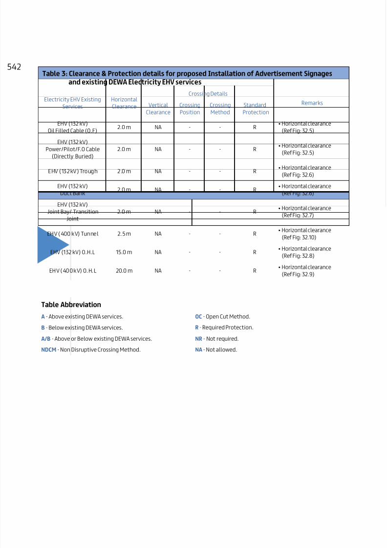
8/15/2019 Dewa Latest Reg 2014
http://slidepdf.com/reader/full/dewa-latest-reg-2014 564/817
Table 3: Clearance & Protection details for proposed Installation of Advertisement Signages
and existing DEWA Electricity EHV services
Electricity EHV Existing
Services
Horizontal
Clearance
Crossing DetailsRemarksVertical
Clearance
Crossing
Position
Crossing
Method
Standard
Protection
NA - - R
NA - - R
NA - - R
Duct Bank NA - - R
Joint Bay/ Transition
Joint
NA - - R
NA - - R
15.0 m NA - - R
NA - - R
Table Abbreviation
A - Above existing DEWA services. OC - Open Cut Method.
B - Below existing DEWA services. R - Required Protection.
A/B - Above or Below existing DEWA services. NR - Not required.
NDCM - Non Disruptive Crossing Method. NA - Not allowed.

8/15/2019 Dewa Latest Reg 2014
http://slidepdf.com/reader/full/dewa-latest-reg-2014 565/817

8/15/2019 Dewa Latest Reg 2014
http://slidepdf.com/reader/full/dewa-latest-reg-2014 566/817

8/15/2019 Dewa Latest Reg 2014
http://slidepdf.com/reader/full/dewa-latest-reg-2014 567/817

8/15/2019 Dewa Latest Reg 2014
http://slidepdf.com/reader/full/dewa-latest-reg-2014 568/817

8/15/2019 Dewa Latest Reg 2014
http://slidepdf.com/reader/full/dewa-latest-reg-2014 569/817

8/15/2019 Dewa Latest Reg 2014
http://slidepdf.com/reader/full/dewa-latest-reg-2014 570/817
Table 4: Clearance & Protection details for proposed Installation of Advertisement Signages
and existing DEWA Gas/Fuel services
Services
Horizontal
Clearance
Crossing DetailsRemarksVertical
Clearance
Crossing
Position
Crossing
Method
Standard
Protection
NA - - R
10.0 m NA - R
Table Abbreviation
A - Above existing DEWA services. OC - Open Cut Method.
B - Below existing DEWA services. R - Required Protection.
A/B - Above or Below existing DEWA services. NR - Not required.
NDCM - Non Disruptive Crossing Method. NA - Not allowed.
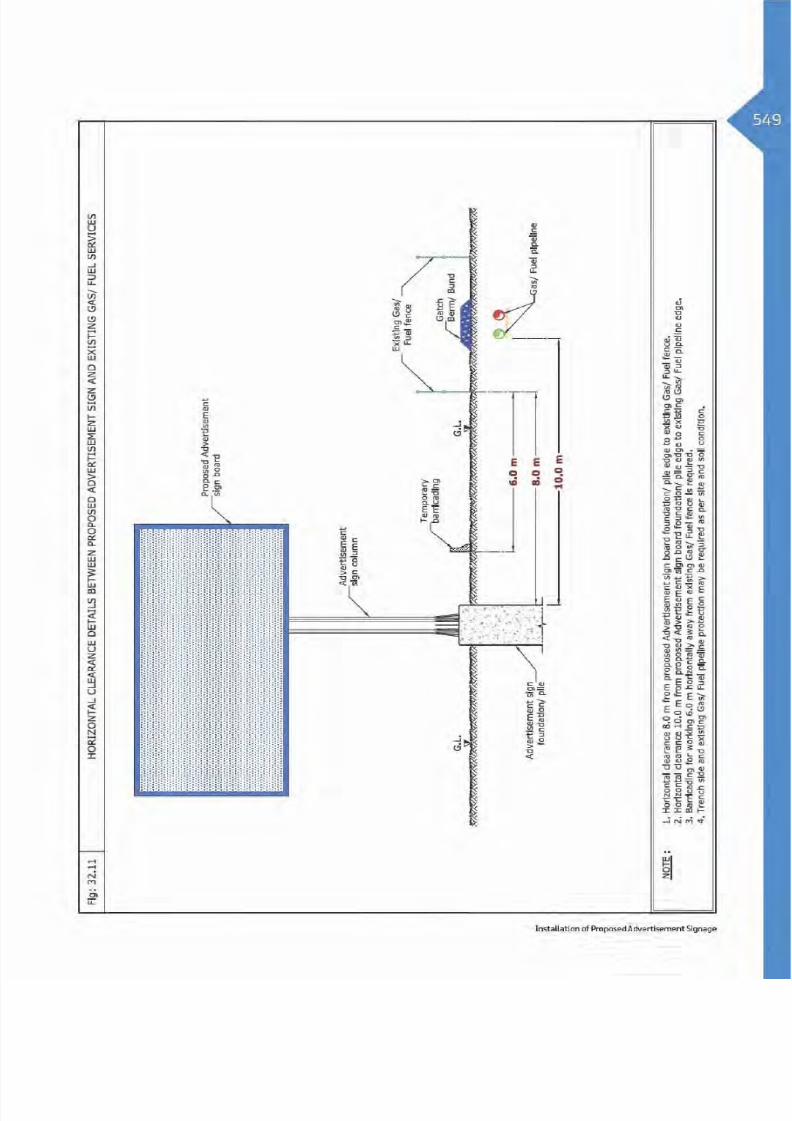
8/15/2019 Dewa Latest Reg 2014
http://slidepdf.com/reader/full/dewa-latest-reg-2014 571/817

8/15/2019 Dewa Latest Reg 2014
http://slidepdf.com/reader/full/dewa-latest-reg-2014 572/817

8/15/2019 Dewa Latest Reg 2014
http://slidepdf.com/reader/full/dewa-latest-reg-2014 573/817

8/15/2019 Dewa Latest Reg 2014
http://slidepdf.com/reader/full/dewa-latest-reg-2014 574/817

8/15/2019 Dewa Latest Reg 2014
http://slidepdf.com/reader/full/dewa-latest-reg-2014 575/817
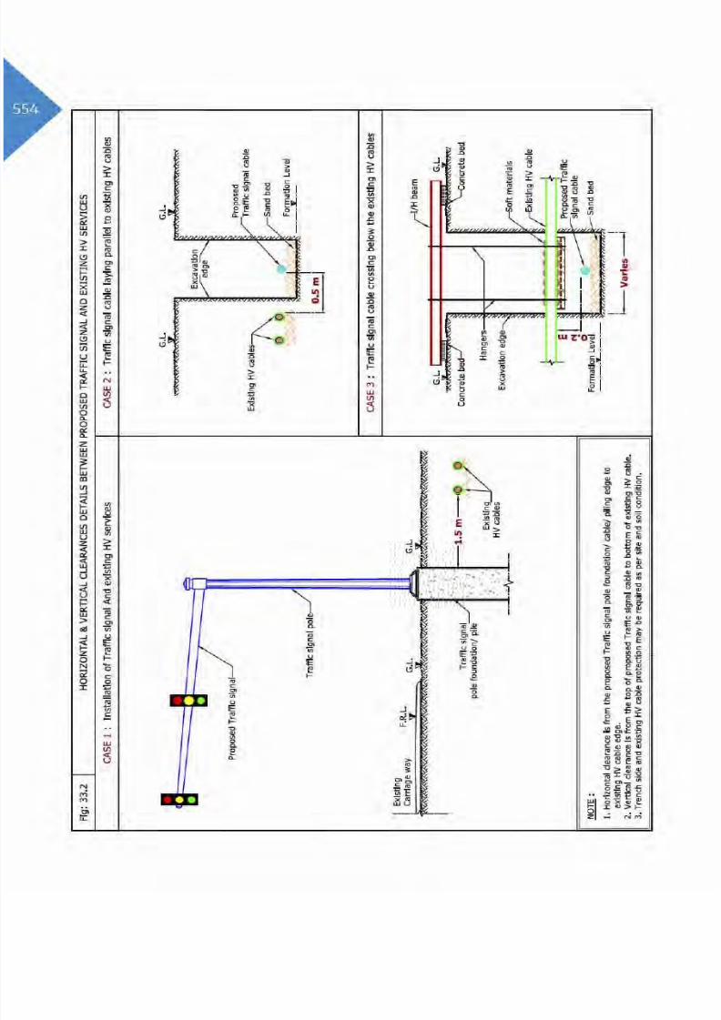
8/15/2019 Dewa Latest Reg 2014
http://slidepdf.com/reader/full/dewa-latest-reg-2014 576/817

8/15/2019 Dewa Latest Reg 2014
http://slidepdf.com/reader/full/dewa-latest-reg-2014 577/817

8/15/2019 Dewa Latest Reg 2014
http://slidepdf.com/reader/full/dewa-latest-reg-2014 578/817

8/15/2019 Dewa Latest Reg 2014
http://slidepdf.com/reader/full/dewa-latest-reg-2014 579/817
557Table 3: Clearance & Protection details for proposed Installation of Traffic Signal and existing
DEWA Electricity EHV services
ElectricityEHV Existing
Services
Proposed
Traffic Signal
Horizontal
Clearance
Crossing DetailsRemarksVertical
Clearance
Crossing
Position
Crossing
Method
Standard
Protection
NA - -
R
Cable 1.0 m 0.5 m B OC
Power/Pilot/
NA - -
R
Cable 1.0 m 0.5 m B OC
Trough
NA - -
R
Cable 1.0 m 0.5 m B OC
Duct Bank
NA - -
R
Cable 1.0 m 0.5 m B OC
Joint Bay/
Transition Joint
NA - -
R
Cable 1.0 m NA - -
Tunnel
NA - OC R
Cable 1.0 m A OC R
O.H.L
Traffic Signal
Pole15.0 m NA - - -
O.H.L
Traffic Signal
Pole NA - - -
Table Abbreviation
A - Above existing DEWA services. OC - Open Cut Method.
B - Below existing DEWA services. R - Required Protection.
A/B - Above or Below existing DEWA services. NR - Not required.
NDCM - Non Disruptive Crossing Method. NA - Not allowed.
Installation of Proposed Traffic Signal

8/15/2019 Dewa Latest Reg 2014
http://slidepdf.com/reader/full/dewa-latest-reg-2014 580/817

8/15/2019 Dewa Latest Reg 2014
http://slidepdf.com/reader/full/dewa-latest-reg-2014 581/817

8/15/2019 Dewa Latest Reg 2014
http://slidepdf.com/reader/full/dewa-latest-reg-2014 582/817

8/15/2019 Dewa Latest Reg 2014
http://slidepdf.com/reader/full/dewa-latest-reg-2014 583/817

8/15/2019 Dewa Latest Reg 2014
http://slidepdf.com/reader/full/dewa-latest-reg-2014 584/817

8/15/2019 Dewa Latest Reg 2014
http://slidepdf.com/reader/full/dewa-latest-reg-2014 585/817

8/15/2019 Dewa Latest Reg 2014
http://slidepdf.com/reader/full/dewa-latest-reg-2014 586/817

8/15/2019 Dewa Latest Reg 2014
http://slidepdf.com/reader/full/dewa-latest-reg-2014 587/817

8/15/2019 Dewa Latest Reg 2014
http://slidepdf.com/reader/full/dewa-latest-reg-2014 588/817

8/15/2019 Dewa Latest Reg 2014
http://slidepdf.com/reader/full/dewa-latest-reg-2014 589/817

8/15/2019 Dewa Latest Reg 2014
http://slidepdf.com/reader/full/dewa-latest-reg-2014 590/817

8/15/2019 Dewa Latest Reg 2014
http://slidepdf.com/reader/full/dewa-latest-reg-2014 591/817

8/15/2019 Dewa Latest Reg 2014
http://slidepdf.com/reader/full/dewa-latest-reg-2014 592/817
70Table 3: Clearance & Protection details for proposed Installation of Address/Traffic Sign and
existing DEWA Electricity EHV services
Electricity EHV Existing
Services
Horizontal
Clearance
Crossing DetailsRemarksVertical
Clearance
Crossing
Position
Crossing
Method
Standard
Protection
NA - - R
NA - - R
NA - - R
Duct Bank NA - - R
Joint Bay/ Transition
Joint
NA - - R
NA - - R
15.0 m NA - - R
NA - - R
Table Abbreviation
A - Above existing DEWA services. OC - Open Cut Method.
B - Below existing DEWA services. R - Required Protection.
A/B - Above or Below existing DEWA services. NR - Not required.
NDCM - Non Disruptive Crossing Method. NA - Not allowed.

8/15/2019 Dewa Latest Reg 2014
http://slidepdf.com/reader/full/dewa-latest-reg-2014 593/817

8/15/2019 Dewa Latest Reg 2014
http://slidepdf.com/reader/full/dewa-latest-reg-2014 594/817
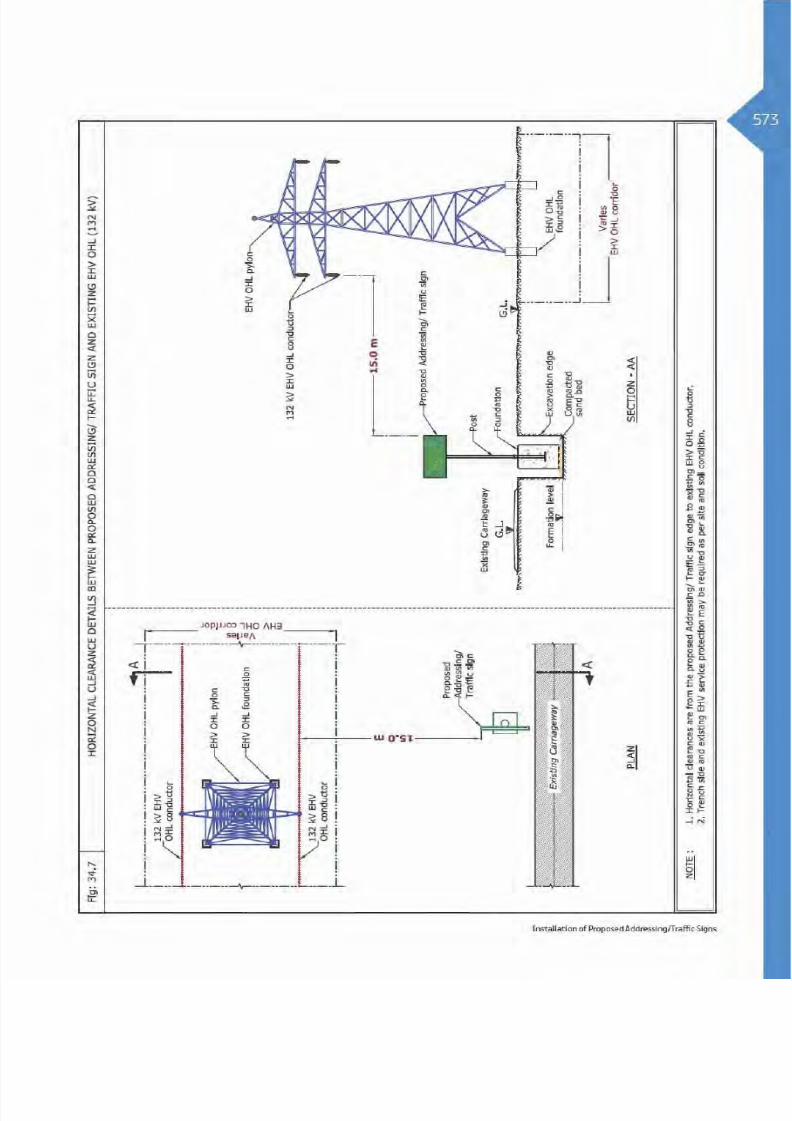
8/15/2019 Dewa Latest Reg 2014
http://slidepdf.com/reader/full/dewa-latest-reg-2014 595/817

8/15/2019 Dewa Latest Reg 2014
http://slidepdf.com/reader/full/dewa-latest-reg-2014 596/817

8/15/2019 Dewa Latest Reg 2014
http://slidepdf.com/reader/full/dewa-latest-reg-2014 597/817

8/15/2019 Dewa Latest Reg 2014
http://slidepdf.com/reader/full/dewa-latest-reg-2014 598/817
Table 4: Clearance & Protection details for proposed Installation of Address/Traffic Sign and
existing DEWA Gas/Fuel services
Services
Horizontal
Clearance
Crossing DetailsRemarksVertical
Clearance
Crossing
Position
Crossing
Method
Standard
Protection
NA - - R
10.0 m NA - - R
Table Abbreviation
A - Above existing DEWA services. OC - Open Cut Method.
B - Below existing DEWA services. R - Required Protection.
A/B - Above or Below existing DEWA services. NR - Not required.
NDCM - Non Disruptive Crossing Method. NA - Not allowed.

8/15/2019 Dewa Latest Reg 2014
http://slidepdf.com/reader/full/dewa-latest-reg-2014 599/817

8/15/2019 Dewa Latest Reg 2014
http://slidepdf.com/reader/full/dewa-latest-reg-2014 600/817

8/15/2019 Dewa Latest Reg 2014
http://slidepdf.com/reader/full/dewa-latest-reg-2014 601/817

8/15/2019 Dewa Latest Reg 2014
http://slidepdf.com/reader/full/dewa-latest-reg-2014 602/817
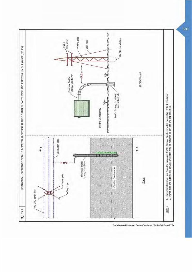
8/15/2019 Dewa Latest Reg 2014
http://slidepdf.com/reader/full/dewa-latest-reg-2014 603/817

8/15/2019 Dewa Latest Reg 2014
http://slidepdf.com/reader/full/dewa-latest-reg-2014 604/817
Table 3: Clearance & Protection details for proposed Installation of Traffic Gantry/Cantilever
and existing DEWA Electricity EHV services
Electricity EHV Existing
Services
Horizontal
Clearance
Crossing DetailsRemarksVertical
Clearance
Crossing
Position
Crossing
Method
Standard
Protection
NA - - R
NA - - R
NA - - R
Duct Bank NA - - R
Joint Bay/ Transition
Joint
NA - - R
NA - - R
15.0 m NA - - R
NA - - R
Table Abbreviation
A - Above existing DEWA services. OC - Open Cut Method.
B - Below existing DEWA services. R - Required Protection.
A/B - Above or Below existing DEWA services. NR - Not required.
NDCM - Non Disruptive Crossing Method. NA - Not allowed.

8/15/2019 Dewa Latest Reg 2014
http://slidepdf.com/reader/full/dewa-latest-reg-2014 605/817

8/15/2019 Dewa Latest Reg 2014
http://slidepdf.com/reader/full/dewa-latest-reg-2014 606/817

8/15/2019 Dewa Latest Reg 2014
http://slidepdf.com/reader/full/dewa-latest-reg-2014 607/817

8/15/2019 Dewa Latest Reg 2014
http://slidepdf.com/reader/full/dewa-latest-reg-2014 608/817

8/15/2019 Dewa Latest Reg 2014
http://slidepdf.com/reader/full/dewa-latest-reg-2014 609/817

8/15/2019 Dewa Latest Reg 2014
http://slidepdf.com/reader/full/dewa-latest-reg-2014 610/817

8/15/2019 Dewa Latest Reg 2014
http://slidepdf.com/reader/full/dewa-latest-reg-2014 611/817

8/15/2019 Dewa Latest Reg 2014
http://slidepdf.com/reader/full/dewa-latest-reg-2014 612/817
OHL Warning/Head Room Gantry
36.1 Introduction
head room gantry is to restrict the height of vehiclesor equipment that intends to cross under the OHL/existing structure, and to ensure that the minimumsafe vertical clearance is maintained. OHL warning/head room gantries are installed on roads well inadvance in the direction of traffic flow.
The gantry structures are fixed on concrete foundationwithin Right Of Way. Therefore it is important duringconstruction activities to protect DEWA existing assetsas per specified standards.

8/15/2019 Dewa Latest Reg 2014
http://slidepdf.com/reader/full/dewa-latest-reg-2014 613/817

8/15/2019 Dewa Latest Reg 2014
http://slidepdf.com/reader/full/dewa-latest-reg-2014 614/817
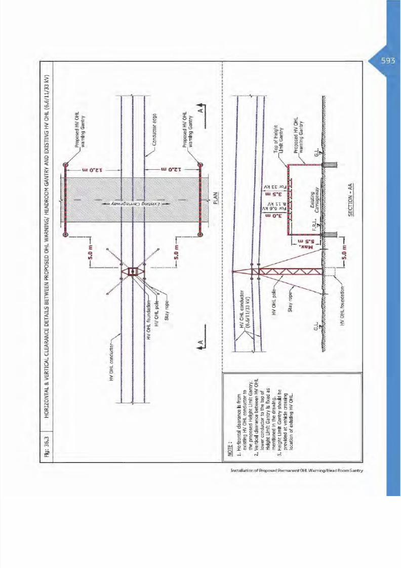
8/15/2019 Dewa Latest Reg 2014
http://slidepdf.com/reader/full/dewa-latest-reg-2014 615/817

8/15/2019 Dewa Latest Reg 2014
http://slidepdf.com/reader/full/dewa-latest-reg-2014 616/817
Table 3: Clearance & Protection details for proposed OHL Warning/Head Room gantry and
existing DEWA Electricity EHV services
Electricity EHV Existing
Services
Horizontal
Clearance
Crossing DetailsRemarksVertical
Clearance
Crossing
Position
Crossing
Method
Standard
Protection
NA - - R
NA - - R
NA - - R
Duct Bank NA - - R
Joint Bay/ Transition
Joint
NA - - R
NA - - R
100.0 m
4.5 m
B - R
7.5 m
Table Abbreviation
A - Above existing DEWA services. OC - Open Cut Method.
B - Below existing DEWA services. R - Required Protection.
A/B - Above or Below existing DEWA services. NR - Not required.
NDCM - Non Disruptive Crossing Method. NA - Not allowed.

8/15/2019 Dewa Latest Reg 2014
http://slidepdf.com/reader/full/dewa-latest-reg-2014 617/817

8/15/2019 Dewa Latest Reg 2014
http://slidepdf.com/reader/full/dewa-latest-reg-2014 618/817

8/15/2019 Dewa Latest Reg 2014
http://slidepdf.com/reader/full/dewa-latest-reg-2014 619/817

8/15/2019 Dewa Latest Reg 2014
http://slidepdf.com/reader/full/dewa-latest-reg-2014 620/817

8/15/2019 Dewa Latest Reg 2014
http://slidepdf.com/reader/full/dewa-latest-reg-2014 621/817

8/15/2019 Dewa Latest Reg 2014
http://slidepdf.com/reader/full/dewa-latest-reg-2014 622/817
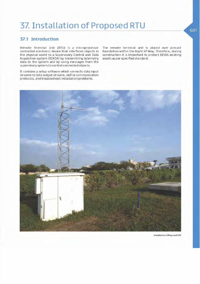
8/15/2019 Dewa Latest Reg 2014
http://slidepdf.com/reader/full/dewa-latest-reg-2014 623/817

8/15/2019 Dewa Latest Reg 2014
http://slidepdf.com/reader/full/dewa-latest-reg-2014 624/817

8/15/2019 Dewa Latest Reg 2014
http://slidepdf.com/reader/full/dewa-latest-reg-2014 625/817

8/15/2019 Dewa Latest Reg 2014
http://slidepdf.com/reader/full/dewa-latest-reg-2014 626/817

8/15/2019 Dewa Latest Reg 2014
http://slidepdf.com/reader/full/dewa-latest-reg-2014 627/817
Table 3: Clearance & Protection details for proposed RTU (Remote Terminal Unit) and existing
DEWA Electricity EHV services
Electricity EHV Existing
Services
Horizontal
Clearance
Crossing DetailsRemarksVertical
Clearance
Crossing
Position
Crossing
Method
Standard
Protection
NA - - -
NA - - -
NA - - -
Duct Bank NA - - -
Joint Bay/ Transition
Joint
NA - - -
NA - - -
5.0 m
4.5 m
B - -
7.5 m
Table Abbreviation
A - Above existing DEWA services. OC - Open Cut Method.
B - Below existing DEWA services. R - Required Protection.
A/B - Above or Below existing DEWA services. NR - Not required.
NDCM - Non Disruptive Crossing Method. NA - Not allowed.
Installation of Proposed RTU

8/15/2019 Dewa Latest Reg 2014
http://slidepdf.com/reader/full/dewa-latest-reg-2014 628/817

8/15/2019 Dewa Latest Reg 2014
http://slidepdf.com/reader/full/dewa-latest-reg-2014 629/817

8/15/2019 Dewa Latest Reg 2014
http://slidepdf.com/reader/full/dewa-latest-reg-2014 630/817

8/15/2019 Dewa Latest Reg 2014
http://slidepdf.com/reader/full/dewa-latest-reg-2014 631/817

8/15/2019 Dewa Latest Reg 2014
http://slidepdf.com/reader/full/dewa-latest-reg-2014 632/817
Table 4: Clearance & Protection details for proposed RTU (Remote Terminal Unit) and existing
DEWA Gas/Fuel services
Services
Horizontal
Clearance
Crossing DetailsRemarksVertical
Clearance
Crossing
Position
Crossing
Method
Standard
Protection
NA - - -
10.0 m NA - - -
Table Abbreviation
A - Above existing DEWA services. OC - Open Cut Method.
B - Below existing DEWA services. R - Required Protection.
A/B - Above or Below existing DEWA services. NR - Not required.
NDCM - Non Disruptive Crossing Method. NA - Not allowed.

8/15/2019 Dewa Latest Reg 2014
http://slidepdf.com/reader/full/dewa-latest-reg-2014 633/817

8/15/2019 Dewa Latest Reg 2014
http://slidepdf.com/reader/full/dewa-latest-reg-2014 634/817

8/15/2019 Dewa Latest Reg 2014
http://slidepdf.com/reader/full/dewa-latest-reg-2014 635/817

8/15/2019 Dewa Latest Reg 2014
http://slidepdf.com/reader/full/dewa-latest-reg-2014 636/817

8/15/2019 Dewa Latest Reg 2014
http://slidepdf.com/reader/full/dewa-latest-reg-2014 637/817
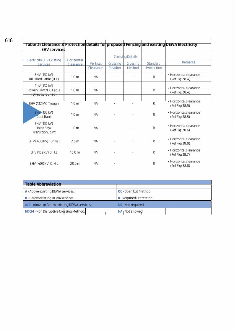
8/15/2019 Dewa Latest Reg 2014
http://slidepdf.com/reader/full/dewa-latest-reg-2014 638/817
Table 3: Clearance & Protection details for proposed Fencing and existing DEWA Electricity
EHV services
Electricity EHV Existing
Services
Horizontal
Clearance
Crossing DetailsRemarksVertical
Clearance
Crossing
Position
Crossing
Method
Standard
Protection
1.0 m NA - - R
1.0 m NA - - R
1.0 m NA - - R
Duct Bank 1.0 m NA - - R
Joint Bay/
Transition Joint
1.0 m NA - - R
NA - - R
15.0 m NA - - R
NA - R
Table Abbreviation
A - Above existing DEWA services. OC - Open Cut Method.
B - Below existing DEWA services. R - Required Protection.
A/B - Above or Below existing DEWA services. NR - Not required.
NDCM - Non Disruptive Crossing Method. NA - Not allowed.

8/15/2019 Dewa Latest Reg 2014
http://slidepdf.com/reader/full/dewa-latest-reg-2014 639/817

8/15/2019 Dewa Latest Reg 2014
http://slidepdf.com/reader/full/dewa-latest-reg-2014 640/817

8/15/2019 Dewa Latest Reg 2014
http://slidepdf.com/reader/full/dewa-latest-reg-2014 641/817

8/15/2019 Dewa Latest Reg 2014
http://slidepdf.com/reader/full/dewa-latest-reg-2014 642/817

8/15/2019 Dewa Latest Reg 2014
http://slidepdf.com/reader/full/dewa-latest-reg-2014 643/817

8/15/2019 Dewa Latest Reg 2014
http://slidepdf.com/reader/full/dewa-latest-reg-2014 644/817

8/15/2019 Dewa Latest Reg 2014
http://slidepdf.com/reader/full/dewa-latest-reg-2014 645/817

8/15/2019 Dewa Latest Reg 2014
http://slidepdf.com/reader/full/dewa-latest-reg-2014 646/817

8/15/2019 Dewa Latest Reg 2014
http://slidepdf.com/reader/full/dewa-latest-reg-2014 647/817

8/15/2019 Dewa Latest Reg 2014
http://slidepdf.com/reader/full/dewa-latest-reg-2014 648/817

8/15/2019 Dewa Latest Reg 2014
http://slidepdf.com/reader/full/dewa-latest-reg-2014 649/817

8/15/2019 Dewa Latest Reg 2014
http://slidepdf.com/reader/full/dewa-latest-reg-2014 650/817
Table 3: Clearance & Protection details for proposed Site office and existing DEWA Electricity
EHV services
Electricity EHV Existing
Services
Horizontal
Clearance
Crossing DetailsRemarksVertical
Clearance
Crossing
Position
Crossing
Method
Standard
Protection
NA - - R
NA - - R
NA - - R
Duct Bank NA - - R
Joint Bay/ Transition
Joint
NA - - R
NA - - R
NA - - -
NA - - -
Table Abbreviation
A - Above existing DEWA services. OC - Open Cut Method.
B - Below existing DEWA services. R - Required Protection.
A/B - Above or Below existing DEWA services. NR - Not required.
NDCM - Non Disruptive Crossing Method. NA - Not allowed.

8/15/2019 Dewa Latest Reg 2014
http://slidepdf.com/reader/full/dewa-latest-reg-2014 651/817

8/15/2019 Dewa Latest Reg 2014
http://slidepdf.com/reader/full/dewa-latest-reg-2014 652/817

8/15/2019 Dewa Latest Reg 2014
http://slidepdf.com/reader/full/dewa-latest-reg-2014 653/817

8/15/2019 Dewa Latest Reg 2014
http://slidepdf.com/reader/full/dewa-latest-reg-2014 654/817

8/15/2019 Dewa Latest Reg 2014
http://slidepdf.com/reader/full/dewa-latest-reg-2014 655/817

8/15/2019 Dewa Latest Reg 2014
http://slidepdf.com/reader/full/dewa-latest-reg-2014 656/817

8/15/2019 Dewa Latest Reg 2014
http://slidepdf.com/reader/full/dewa-latest-reg-2014 657/817

8/15/2019 Dewa Latest Reg 2014
http://slidepdf.com/reader/full/dewa-latest-reg-2014 658/817

8/15/2019 Dewa Latest Reg 2014
http://slidepdf.com/reader/full/dewa-latest-reg-2014 659/817

8/15/2019 Dewa Latest Reg 2014
http://slidepdf.com/reader/full/dewa-latest-reg-2014 660/817

8/15/2019 Dewa Latest Reg 2014
http://slidepdf.com/reader/full/dewa-latest-reg-2014 661/817

8/15/2019 Dewa Latest Reg 2014
http://slidepdf.com/reader/full/dewa-latest-reg-2014 662/817
Table 3: Clearance & Protection details for proposed Sound barrier and existing DEWA Electricity
EHV services
Electricity EHV Existing
Services
Horizontal
Clearance
Crossing DetailsRemarksVertical
Clearance
Crossing
Position
Crossing
Method
Standard
Protection
NA - - R
NA - - R
NA - - R
Duct Bank NA - - R
Joint Bay/ Transition
Joint
NA - - R
NA - - R
15.0 m NA - - R
NA - - R
Table Abbreviation
A - Above existing DEWA services. OC - Open Cut Method.
B - Below existing DEWA services. R - Required Protection.
A/B - Above or Below existing DEWA services. NR - Not required.
NDCM - Non Disruptive Crossing Method. NA - Not allowed.

8/15/2019 Dewa Latest Reg 2014
http://slidepdf.com/reader/full/dewa-latest-reg-2014 663/817

8/15/2019 Dewa Latest Reg 2014
http://slidepdf.com/reader/full/dewa-latest-reg-2014 664/817

8/15/2019 Dewa Latest Reg 2014
http://slidepdf.com/reader/full/dewa-latest-reg-2014 665/817

8/15/2019 Dewa Latest Reg 2014
http://slidepdf.com/reader/full/dewa-latest-reg-2014 666/817

8/15/2019 Dewa Latest Reg 2014
http://slidepdf.com/reader/full/dewa-latest-reg-2014 667/817

8/15/2019 Dewa Latest Reg 2014
http://slidepdf.com/reader/full/dewa-latest-reg-2014 668/817

8/15/2019 Dewa Latest Reg 2014
http://slidepdf.com/reader/full/dewa-latest-reg-2014 669/817

8/15/2019 Dewa Latest Reg 2014
http://slidepdf.com/reader/full/dewa-latest-reg-2014 670/817

8/15/2019 Dewa Latest Reg 2014
http://slidepdf.com/reader/full/dewa-latest-reg-2014 671/817
CHAPTER 4
GENERAL PROJECTS

8/15/2019 Dewa Latest Reg 2014
http://slidepdf.com/reader/full/dewa-latest-reg-2014 672/817

8/15/2019 Dewa Latest Reg 2014
http://slidepdf.com/reader/full/dewa-latest-reg-2014 673/817

8/15/2019 Dewa Latest Reg 2014
http://slidepdf.com/reader/full/dewa-latest-reg-2014 674/817

8/15/2019 Dewa Latest Reg 2014
http://slidepdf.com/reader/full/dewa-latest-reg-2014 675/817

8/15/2019 Dewa Latest Reg 2014
http://slidepdf.com/reader/full/dewa-latest-reg-2014 676/817

8/15/2019 Dewa Latest Reg 2014
http://slidepdf.com/reader/full/dewa-latest-reg-2014 677/817

8/15/2019 Dewa Latest Reg 2014
http://slidepdf.com/reader/full/dewa-latest-reg-2014 678/817
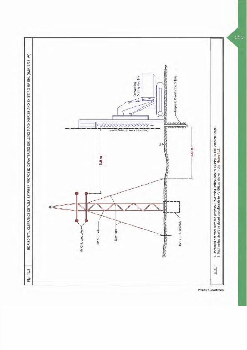
8/15/2019 Dewa Latest Reg 2014
http://slidepdf.com/reader/full/dewa-latest-reg-2014 679/817
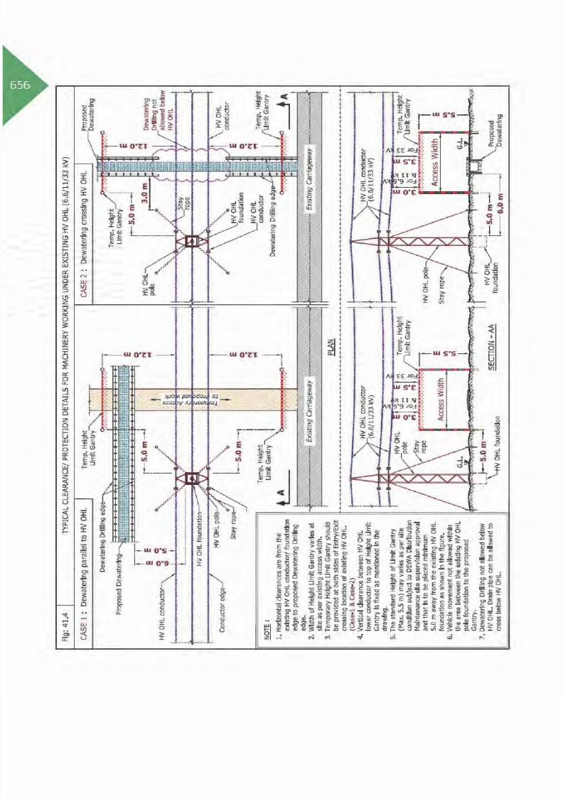
8/15/2019 Dewa Latest Reg 2014
http://slidepdf.com/reader/full/dewa-latest-reg-2014 680/817

8/15/2019 Dewa Latest Reg 2014
http://slidepdf.com/reader/full/dewa-latest-reg-2014 681/817

8/15/2019 Dewa Latest Reg 2014
http://slidepdf.com/reader/full/dewa-latest-reg-2014 682/817
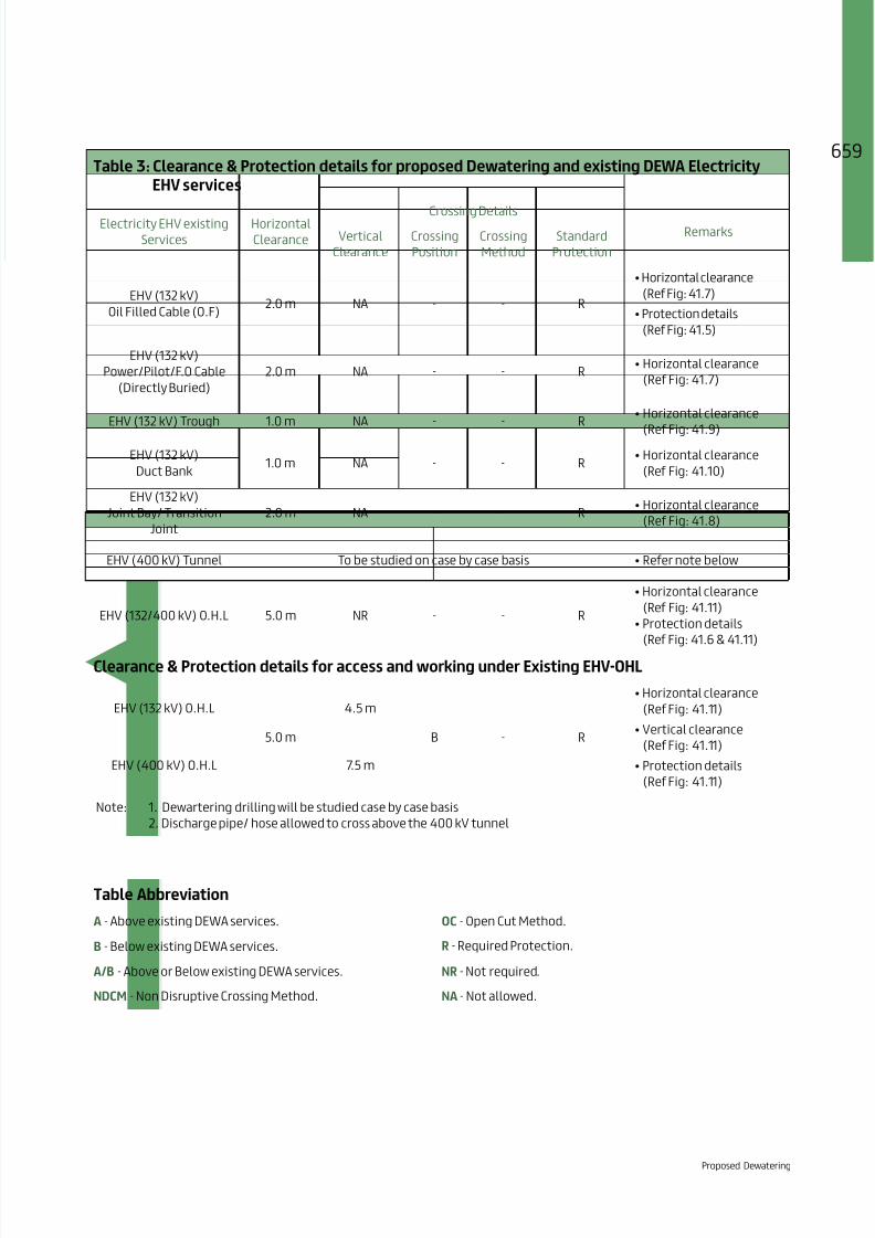
8/15/2019 Dewa Latest Reg 2014
http://slidepdf.com/reader/full/dewa-latest-reg-2014 683/817
659Table 3: Clearance & Protection details for proposed Dewatering and existing DEWA Electricity
EHV services
Electricity EHV existing
Services
Horizontal
Clearance
Crossing DetailsRemarksVertical
Clearance
Crossing
Position
Crossing
Method
Standard
Protection
EHV (132 kV)
Oil Filled Cable (O.F)2.0 m NA - - R
(Ref Fig: 41.7)
(Ref Fig: 41.5)
EHV (132 kV)
Power/Pilot/F.O Cable
(Directly Buried)
2.0 m NA - - R
(Ref Fig: 41.7)
EHV (132 kV) Trough 1.0 m NA - - R
(Ref Fig: 41.9)EHV (132 kV)
Duct Bank1.0 m NA - - R
(Ref Fig: 41.10)
EHV (132 kV)
Joint Bay/ Transition
Joint
2.0 m NA - - R
(Ref Fig: 41.8)
EHV (400 kV) Tunnel To be studied on case by case basis
EHV (132/400 kV) O.H.L 5.0 m NR - - R
(Ref Fig: 41.11)
(Ref Fig: 41.6 & 41.11)
Clearance & Protection details for access and working under Existing EHV-OHL
EHV (132 kV) O.H.L
5.0 m
4.5 m
B - R
(Ref Fig: 41.11)
(Ref Fig: 41.11)
(Ref Fig: 41.11)
EHV (400 kV) O.H.L 7.5 m
Note: 1. Dewartering drilling will be studied case by case basis
2. Discharge pipe/ hose allowed to cross above the 400 kV tunnel
Table Abbreviation
A - Above existing DEWA services. OC - Open Cut Method.
B - Below existing DEWA services. R - Required Protection.
A/B - Above or Below existing DEWA services. NR - Not required.
NDCM - Non Disruptive Crossing Method. NA - Not allowed.
Proposed Dewatering

8/15/2019 Dewa Latest Reg 2014
http://slidepdf.com/reader/full/dewa-latest-reg-2014 684/817
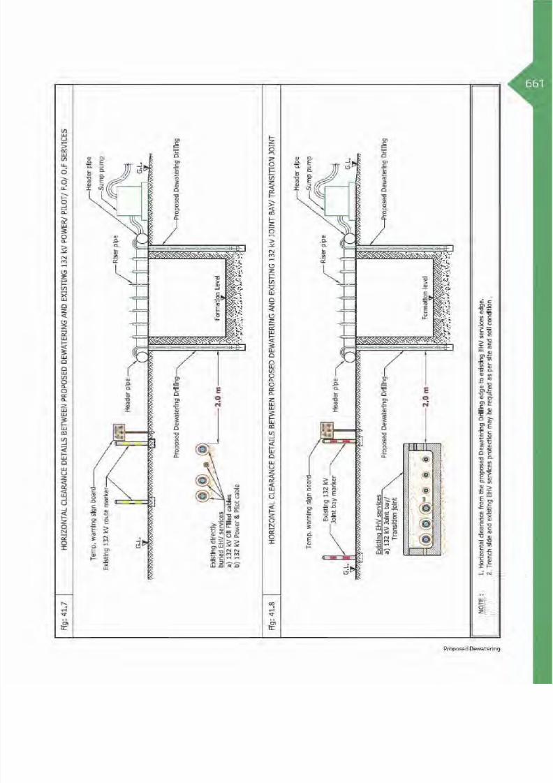
8/15/2019 Dewa Latest Reg 2014
http://slidepdf.com/reader/full/dewa-latest-reg-2014 685/817

8/15/2019 Dewa Latest Reg 2014
http://slidepdf.com/reader/full/dewa-latest-reg-2014 686/817

8/15/2019 Dewa Latest Reg 2014
http://slidepdf.com/reader/full/dewa-latest-reg-2014 687/817

8/15/2019 Dewa Latest Reg 2014
http://slidepdf.com/reader/full/dewa-latest-reg-2014 688/817

8/15/2019 Dewa Latest Reg 2014
http://slidepdf.com/reader/full/dewa-latest-reg-2014 689/817

8/15/2019 Dewa Latest Reg 2014
http://slidepdf.com/reader/full/dewa-latest-reg-2014 690/817
66
42. Proposed Soil Investigation/Borehole
42.1 Introduction
Typical Soil Investigation
To evaluate the suitability of construction site anddisclose/predict the difficulties during constructionand also to enable adequate economic and structuraldesign as per soil condition. The suitability ofconstruction location will be concluded aftertesting various properties of soil collected from theconstruction site.
Construction activity involves boring/drilling andother machinery, borehole location to be away fromDEWA assets as per specified standards.

8/15/2019 Dewa Latest Reg 2014
http://slidepdf.com/reader/full/dewa-latest-reg-2014 691/817

8/15/2019 Dewa Latest Reg 2014
http://slidepdf.com/reader/full/dewa-latest-reg-2014 692/817
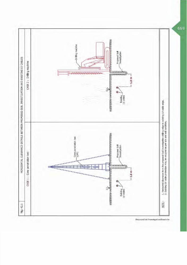
8/15/2019 Dewa Latest Reg 2014
http://slidepdf.com/reader/full/dewa-latest-reg-2014 693/817

8/15/2019 Dewa Latest Reg 2014
http://slidepdf.com/reader/full/dewa-latest-reg-2014 694/817
70Table 2: Clearance & Protection details for Proposed Soil investigation/Bore hole and existing
DEWA Electricity HV services
Electricity HV existing
Services
Horizontal
Clearance
Crossing DetailsRemarksVertical
Clearance
Crossing
Position
Crossing
Method
Standard
Protection
HV
(6.6/11/33 kV)
Power/Pilot Cable and
Joints.
1.5 m NA - - R
(Ref Fig: 42.2)
(Ref Fig: 42.2)
HV
(6.6/11/33 kV) Manhole.1.0 m NA - - R
(Ref Fig: 42.3)
HV
(6.6/11/33 kV) O.H.L.5.0 m NA - - R
(Ref Fig: 42.4)
Clearance & Protection details for access and crossing under Existing HV-OHL
HV
(6.6/11 kV) O.H.L.
5.0 m
3.0 m
B - R
(Ref Fig: 42.5)
(Ref Fig: 42.5)
(Ref Fig: 42.5)
HV
(33 kV) O.H.L.3.5 m
Table Abbreviation
A - Above existing DEWA services. OC - Open Cut Method.
B - Below existing DEWA services. R - Required Protection.
A/B - Above or Below existing DEWA services. NR - Not required.
NDCM - Non Disruptive Crossing Method. NA - Not allowed.

8/15/2019 Dewa Latest Reg 2014
http://slidepdf.com/reader/full/dewa-latest-reg-2014 695/817

8/15/2019 Dewa Latest Reg 2014
http://slidepdf.com/reader/full/dewa-latest-reg-2014 696/817

8/15/2019 Dewa Latest Reg 2014
http://slidepdf.com/reader/full/dewa-latest-reg-2014 697/817

8/15/2019 Dewa Latest Reg 2014
http://slidepdf.com/reader/full/dewa-latest-reg-2014 698/817

8/15/2019 Dewa Latest Reg 2014
http://slidepdf.com/reader/full/dewa-latest-reg-2014 699/817

8/15/2019 Dewa Latest Reg 2014
http://slidepdf.com/reader/full/dewa-latest-reg-2014 700/817

8/15/2019 Dewa Latest Reg 2014
http://slidepdf.com/reader/full/dewa-latest-reg-2014 701/817
677Table 3: Clearance & Protection details for proposed Soil investigation/Bore hole and existing
DEWA Electricity EHV services
Electricity EHV existing
Services
Horizontal
Clearance
Crossing DetailsRemarksVertical
Clearance
Crossing
Position
Crossing
Method
Standard
Protection
EHV (132 kV)
Oil Filled Cable (O.F)
2.0 mNA - - R
(Ref Fig: 42.6)
(Ref Photo: 42.3)
EHV (132 kV)
Power/Pilot/F.O Cable
(Directly Buried)
2.0 mNA - - R
(Ref Fig: 42.6)
(Ref Photo: 42.3)
EHV (132 kV) Trough 2.0 m NA - - R
(Ref Fig: 42.7)
(Ref Photo:42.3)
EHV (132 kV)
Duct Bank2.0 m NA - - R
(Ref Fig: 42.8)
(Ref Photo:42.3)
EHV (132 kV)
Joint Bay/ Transition
Joint
2.0 m NA - - R
(Ref Fig: 42.9)
(Ref Photo:42.3)
EHV (132/400 kV) O.H.L 5.0 m NR - - R
(Ref Fig: 42.10)
(Ref Fig: 42.10)
EHV (400 kV) Tunnel 2.5 m NA - - R
(Ref Fig: 42.11)
(Ref Photo:42.3)
Clearance & Protection details for access and working under Existing EHV-OHL
EHV (132 kV) O.H.L
5.0 m
4.5 m
B - R
(Ref Fig: 42.10)
(Ref Fig: 42.10)
(Ref Fig: 42.10)
EHV (400 kV) O.H.L 7.5 m
Table Abbreviation
A - Above existing DEWA services. OC - Open Cut Method.
B - Below existing DEWA services. R - Required Protection.
A/B - Above or Below existing DEWA services. NR - Not required.
NDCM - Non Disruptive Crossing Method. NA - Not allowed.
Proposed Soil Investigation/Borehole

8/15/2019 Dewa Latest Reg 2014
http://slidepdf.com/reader/full/dewa-latest-reg-2014 702/817

8/15/2019 Dewa Latest Reg 2014
http://slidepdf.com/reader/full/dewa-latest-reg-2014 703/817

8/15/2019 Dewa Latest Reg 2014
http://slidepdf.com/reader/full/dewa-latest-reg-2014 704/817

8/15/2019 Dewa Latest Reg 2014
http://slidepdf.com/reader/full/dewa-latest-reg-2014 705/817

8/15/2019 Dewa Latest Reg 2014
http://slidepdf.com/reader/full/dewa-latest-reg-2014 706/817
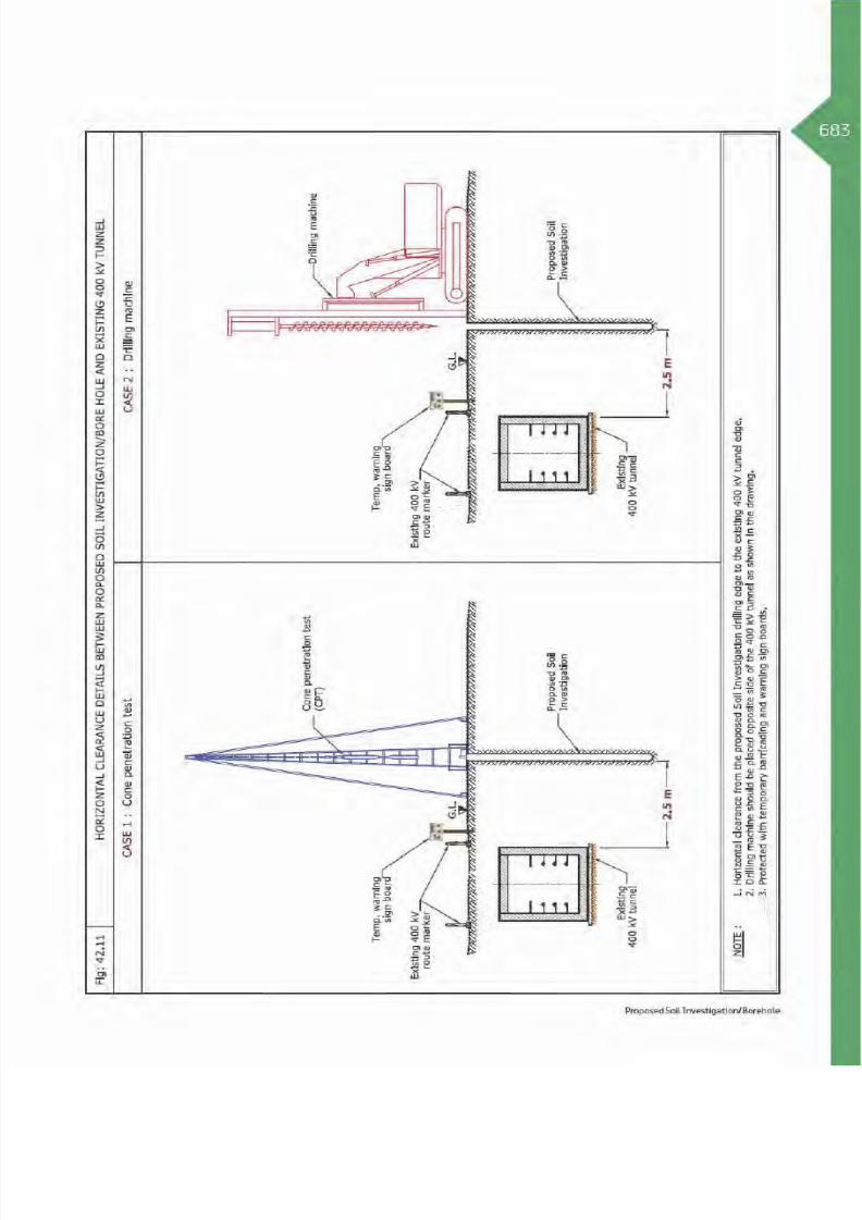
8/15/2019 Dewa Latest Reg 2014
http://slidepdf.com/reader/full/dewa-latest-reg-2014 707/817

8/15/2019 Dewa Latest Reg 2014
http://slidepdf.com/reader/full/dewa-latest-reg-2014 708/817

8/15/2019 Dewa Latest Reg 2014
http://slidepdf.com/reader/full/dewa-latest-reg-2014 709/817
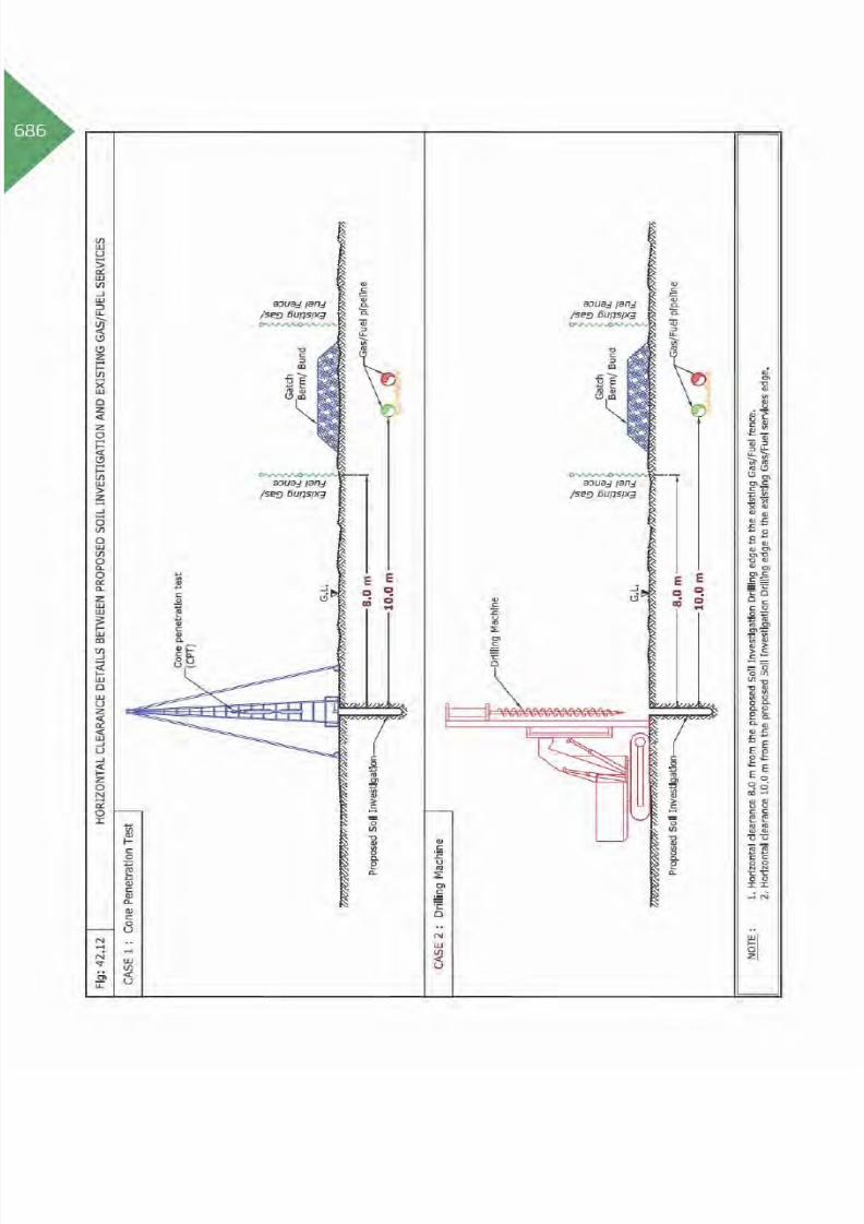
8/15/2019 Dewa Latest Reg 2014
http://slidepdf.com/reader/full/dewa-latest-reg-2014 710/817

8/15/2019 Dewa Latest Reg 2014
http://slidepdf.com/reader/full/dewa-latest-reg-2014 711/817

8/15/2019 Dewa Latest Reg 2014
http://slidepdf.com/reader/full/dewa-latest-reg-2014 712/817

8/15/2019 Dewa Latest Reg 2014
http://slidepdf.com/reader/full/dewa-latest-reg-2014 713/817

8/15/2019 Dewa Latest Reg 2014
http://slidepdf.com/reader/full/dewa-latest-reg-2014 714/817
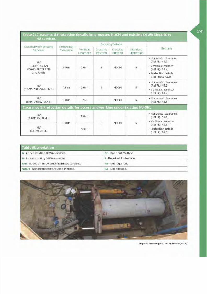
8/15/2019 Dewa Latest Reg 2014
http://slidepdf.com/reader/full/dewa-latest-reg-2014 715/817

8/15/2019 Dewa Latest Reg 2014
http://slidepdf.com/reader/full/dewa-latest-reg-2014 716/817

8/15/2019 Dewa Latest Reg 2014
http://slidepdf.com/reader/full/dewa-latest-reg-2014 717/817

8/15/2019 Dewa Latest Reg 2014
http://slidepdf.com/reader/full/dewa-latest-reg-2014 718/817

8/15/2019 Dewa Latest Reg 2014
http://slidepdf.com/reader/full/dewa-latest-reg-2014 719/817
695Table 3: Clearance & Protection details for proposed NDCM and existing DEWA Electricity
EHV services
ElectricityEHV existing
Services
Horizontal
Clearance
Crossing DetailsRemarksVertical
Clearance
Crossing
Position
Crossing
Method
Standard
Protection
EHV (132 kV)
Oil Filled Cable
(O.F)
2.0 m 2.0 m B NDCM R
EHV (132 kV)
Power/Pilot/
F.O Cable
(Directly Buried)
2.0 m 2.0 m B NDCM R
EHV (132 kV)
Trough 2.0 m 2.0 m B NDCM R
EHV (132 kV)
Duct Bank2.0 m 2.0 m B NDCM R
EHV (132 kV)
Joint Bay/
Transition Joint
5.0 m NA - - -
EHV
(132/400 kV)
O.H.L
5.0 m NR - NDCM R
EHV (400 kV)
Tunnel2.5 m 2.0 m B NDCM R
(Ref Fig:43.7 & 43.8)
Clearance & Protection details for access and working under Existing EHV-OHL
EHV (132 kV)
O.H.L5.0 m
4.5 m
B - R
EHV (400 kV)
O.H.L7.5 m
Table Abbreviation
A - Above existing DEWA services. OC - Open Cut Method.
B - Below existing DEWA services. R - Required Protection.
A/B - Above or Below existing DEWA services. NR - Not required.
NDCM - Non Disruptive Crossing Method. NA - Not allowed.
Proposed Non-Disruptive Crossing Method (NDCM)

8/15/2019 Dewa Latest Reg 2014
http://slidepdf.com/reader/full/dewa-latest-reg-2014 720/817

8/15/2019 Dewa Latest Reg 2014
http://slidepdf.com/reader/full/dewa-latest-reg-2014 721/817

8/15/2019 Dewa Latest Reg 2014
http://slidepdf.com/reader/full/dewa-latest-reg-2014 722/817

8/15/2019 Dewa Latest Reg 2014
http://slidepdf.com/reader/full/dewa-latest-reg-2014 723/817

8/15/2019 Dewa Latest Reg 2014
http://slidepdf.com/reader/full/dewa-latest-reg-2014 724/817

8/15/2019 Dewa Latest Reg 2014
http://slidepdf.com/reader/full/dewa-latest-reg-2014 725/817

8/15/2019 Dewa Latest Reg 2014
http://slidepdf.com/reader/full/dewa-latest-reg-2014 726/817
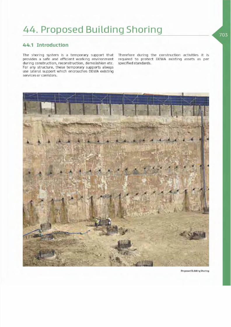
8/15/2019 Dewa Latest Reg 2014
http://slidepdf.com/reader/full/dewa-latest-reg-2014 727/817

8/15/2019 Dewa Latest Reg 2014
http://slidepdf.com/reader/full/dewa-latest-reg-2014 728/817

8/15/2019 Dewa Latest Reg 2014
http://slidepdf.com/reader/full/dewa-latest-reg-2014 729/817

8/15/2019 Dewa Latest Reg 2014
http://slidepdf.com/reader/full/dewa-latest-reg-2014 730/817

8/15/2019 Dewa Latest Reg 2014
http://slidepdf.com/reader/full/dewa-latest-reg-2014 731/817
707Table 3: Clearance & Protection details for proposed Shoring and existing DEWA Electricity
EHV services
Electricity EHV
existing Services
Proposed
Shoring
Horizontal
Clearance
Crossing DetailsRemarksVertical
Clearance
Crossing
Position
Crossing
Method
Standard
Protection
EHV (132 kV)
Oil Filled Cable
(O.F)
Shoring 2.0 m NA - -
R
(Ref Fig:44.4)
Anchoring NR 2.0 m B -
EHV (132 kV)
Power/Pilot/
F.O Cable
(Directly Buried)
Shoring 2.0 m NA - -
R
(Ref Fig:44.4)
Anchoring NR 2.0 m B -
EHV (132 kV)
Trough
Shoring 2.0 m NA - -
R
(Ref Fig:44.5)
Anchoring NR 2.0 m B -
EHV (132 kV)
Duct Bank
Shoring 2.0 m NA - -
R
(Ref Fig:44.5)
Anchoring NR 2.0 m B -
EHV (132 kV)
Joint Bay/
Transition Joint
Shoring 2.0 m NA - -R
(Ref Fig:44.6)
Anchoring NR 2.0 m B -
EHV (132 kV)
O.H.LShoring 15.0 m NA - - R
(Ref Fig:44.7)
EHV (400 kV)
O.H.LShoring 20.0 m NA - - R
(Ref Fig:44.8)
EHV (400 kV)
TunnelTo be studied on case by case basis
Note: The maximum vibration level for civil works not to exceed 15 mm/s PPV
Table Abbreviation
A - Above existing DEWA services. OC - Open Cut Method.
B - Below existing DEWA services. R - Required Protection.
A/B - Above or Below existing DEWA services. NR - Not required.
NDCM - Non Disruptive Crossing Method. NA - Not allowed.
Proposed Building Shoring

8/15/2019 Dewa Latest Reg 2014
http://slidepdf.com/reader/full/dewa-latest-reg-2014 732/817

8/15/2019 Dewa Latest Reg 2014
http://slidepdf.com/reader/full/dewa-latest-reg-2014 733/817
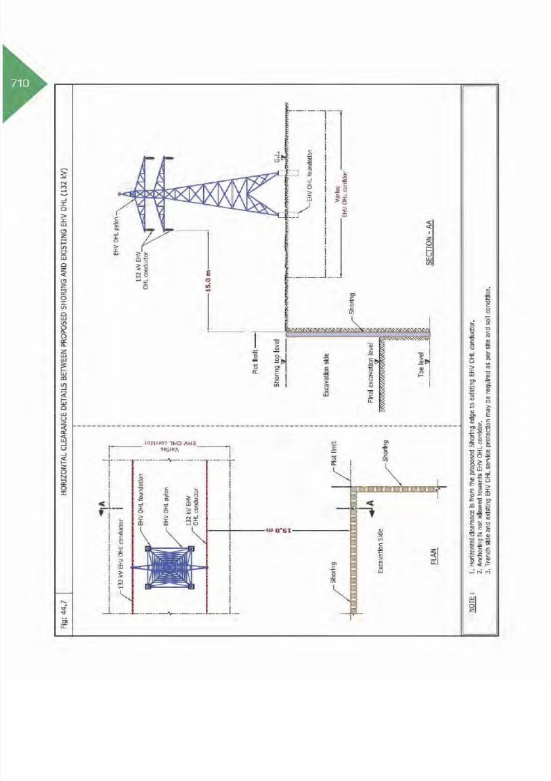
8/15/2019 Dewa Latest Reg 2014
http://slidepdf.com/reader/full/dewa-latest-reg-2014 734/817

8/15/2019 Dewa Latest Reg 2014
http://slidepdf.com/reader/full/dewa-latest-reg-2014 735/817

8/15/2019 Dewa Latest Reg 2014
http://slidepdf.com/reader/full/dewa-latest-reg-2014 736/817

8/15/2019 Dewa Latest Reg 2014
http://slidepdf.com/reader/full/dewa-latest-reg-2014 737/817

8/15/2019 Dewa Latest Reg 2014
http://slidepdf.com/reader/full/dewa-latest-reg-2014 738/817
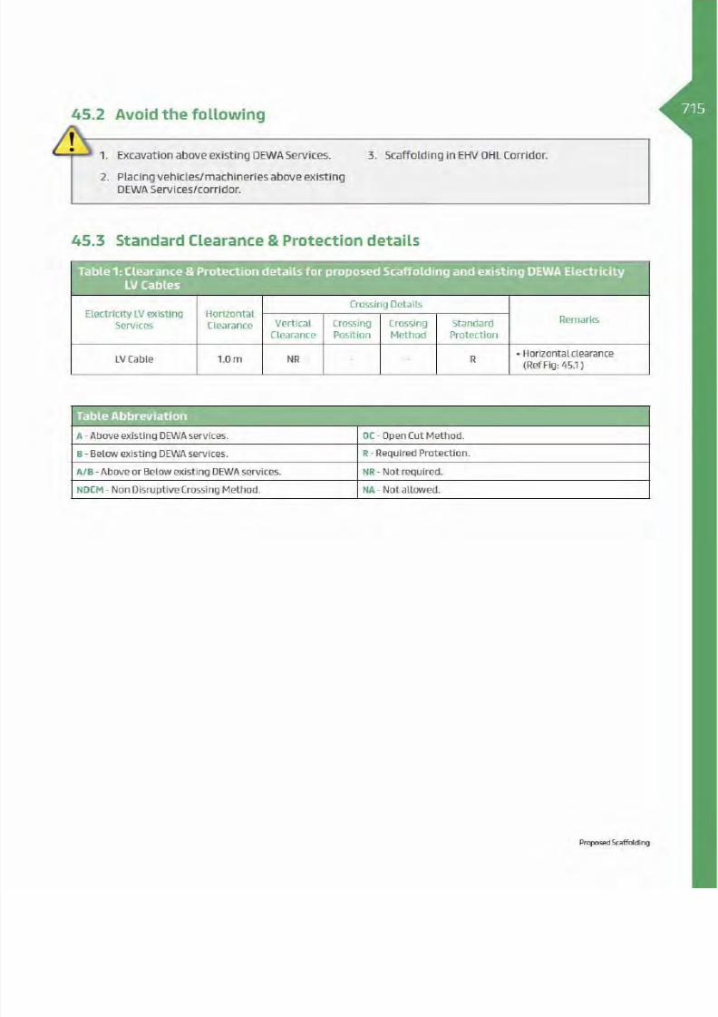
8/15/2019 Dewa Latest Reg 2014
http://slidepdf.com/reader/full/dewa-latest-reg-2014 739/817

8/15/2019 Dewa Latest Reg 2014
http://slidepdf.com/reader/full/dewa-latest-reg-2014 740/817

8/15/2019 Dewa Latest Reg 2014
http://slidepdf.com/reader/full/dewa-latest-reg-2014 741/817
717Table 2: Clearance & Protection details for proposed Scaffolding and existing DEWA Electricity
HV services
Electricity HV existing
Services
Horizontal
Clearance
Crossing DetailsRemarksVertical
Clearance
Crossing
Position
Crossing
Method
Standard
Protection
HV
(6.6/11/33 kV)
Power/Pilot Cable
and Joints
1.0 m NR - - R
(Ref Fig: 45.2)
(Ref Fig: 45.2 )
HV
(6.6/11/33 kV) Manhole1.0 m NR - - R
(Ref Fig: 45.3)
HV
(6.6/11/33 kV) O.H.L.5.0 m NR - - R
(Ref Fig: 45.4)
Clearance & Protection details for access and working under Existing HV-OHL
HV
(6.6/11 kV) O.H.L.
5.0 m
3.0 m
B - R
(Ref Fig: 45.4)
(Ref Fig: 45.4 )
(Ref Fig: 45.4 )
HV
(33 kV) O.H.L.3.5 m
Table Abbreviation
A - Above existing DEWA services. OC - Open Cut Method.
B - Below existing DEWA services. R - Required Protection.
A/B - Above or Below existing DEWA services. NR - Not required.
NDCM - Non Disruptive Crossing Method. NA - Not allowed.
Proposed Scaffolding

8/15/2019 Dewa Latest Reg 2014
http://slidepdf.com/reader/full/dewa-latest-reg-2014 742/817

8/15/2019 Dewa Latest Reg 2014
http://slidepdf.com/reader/full/dewa-latest-reg-2014 743/817

8/15/2019 Dewa Latest Reg 2014
http://slidepdf.com/reader/full/dewa-latest-reg-2014 744/817
20Table 3: Clearance & Protection details for proposed Scaffolding and existing DEWA Electricity
EHV services
Electricity EHV
existing Services
Horizontal
Clearance
Crossing DetailsRemarksVertical
Clearance
Crossing
Position
Crossing
Method
Standard
Protection
EHV (132 kV)
Oil Filled Cable (O.F)1.0 m NR - - R
(Ref Fig: 45.5)
(Ref Fig: 45.5 )
EHV (132 kV)
Power/Pilot/F.O Cable
(Directly Buried)
1.0 m NR - - R
(Ref Fig: 45.5 )
(Ref Fig: 45.5 )
EHV (132 kV) Trough 1.0 m NR - - R
(Ref Fig: 45.6 )
(Ref Fig: 45.6)
EHV (132 kV)
Duct Bank1.0 m NR - - R
(Ref Fig:45.6 )
(Ref Fig: 45.6)
EHV (132 kV)
Joint Bay/
Transition Joint
2.0 m NR - - R
(Ref Fig: 45.7 )
EHV (132 kV) O.H.L NR 15.0 m B - R (Ref Fig: 45.9)
(Ref Fig: 45.9)EHV (400 kV) O.H.L NR 16.5 m B - R
EHV (400 kV) Tunnel 2.5 m NR - - R
(Ref Fig: 45.8)
(Ref Fig: 45.8)
Clearance & Protection details for access and working under Existing EHV-OHL
EHV (132 kV) O.H.L
5.0 m
4.5 m
B - R
(Ref Fig: 45.9 )
(Ref Fig: 45.9)
(Ref Fig: 45.9)EHV (400 kV) O.H.L 7.5 m
Table Abbreviation
A - Above existing DEWA services. OC - Open Cut Method.
B - Below existing DEWA services. R - Required Protection.
A/B - Above or Below existing DEWA services. NR - Not required.
NDCM - Non Disruptive Crossing Method. NA - Not allowed.

8/15/2019 Dewa Latest Reg 2014
http://slidepdf.com/reader/full/dewa-latest-reg-2014 745/817

8/15/2019 Dewa Latest Reg 2014
http://slidepdf.com/reader/full/dewa-latest-reg-2014 746/817

8/15/2019 Dewa Latest Reg 2014
http://slidepdf.com/reader/full/dewa-latest-reg-2014 747/817
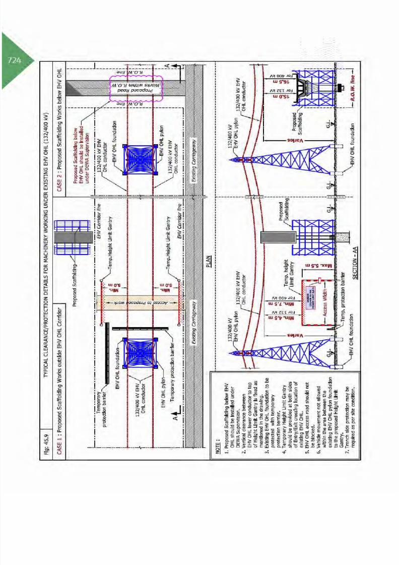
8/15/2019 Dewa Latest Reg 2014
http://slidepdf.com/reader/full/dewa-latest-reg-2014 748/817

8/15/2019 Dewa Latest Reg 2014
http://slidepdf.com/reader/full/dewa-latest-reg-2014 749/817
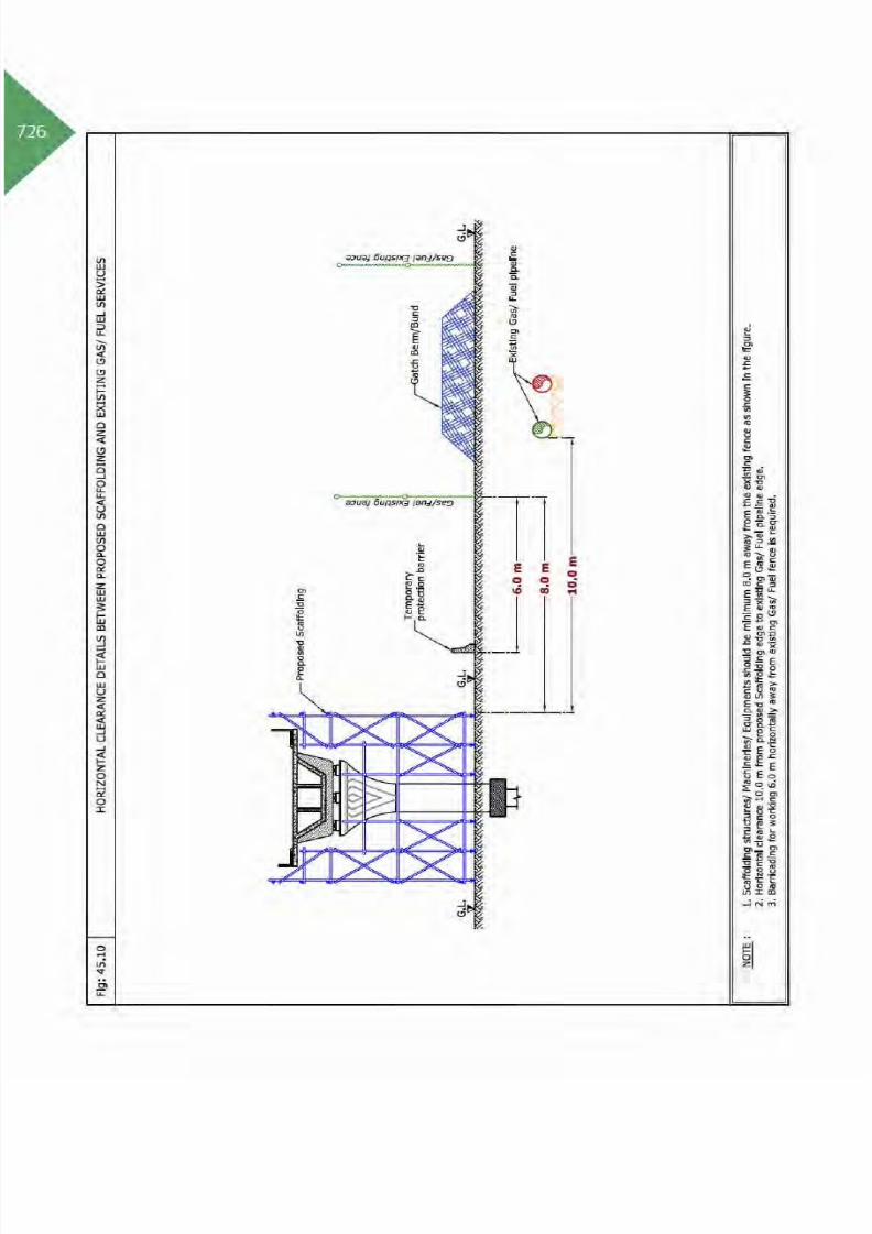
8/15/2019 Dewa Latest Reg 2014
http://slidepdf.com/reader/full/dewa-latest-reg-2014 750/817

8/15/2019 Dewa Latest Reg 2014
http://slidepdf.com/reader/full/dewa-latest-reg-2014 751/817

8/15/2019 Dewa Latest Reg 2014
http://slidepdf.com/reader/full/dewa-latest-reg-2014 752/817

8/15/2019 Dewa Latest Reg 2014
http://slidepdf.com/reader/full/dewa-latest-reg-2014 753/817

8/15/2019 Dewa Latest Reg 2014
http://slidepdf.com/reader/full/dewa-latest-reg-2014 754/817

8/15/2019 Dewa Latest Reg 2014
http://slidepdf.com/reader/full/dewa-latest-reg-2014 755/817
731Table 2: Clearance & Protection details for proposed construction of Utility Manhole/Chamber/
Gully and existing DEWA Electricity HV services
Electricity HV existing
Services
Horizontal
Clearance
Crossing DetailsRemarksVertical
Clearance
Crossing
Position
Crossing
Method
Standard
Protection
HV
(6.6/11/33 kV)
Power/Pilot Cable
and Joints 0.5 m NA
- - R
(Ref Fig: 46.2 - Case 1)
HV
(6.6/11/33 kV) Manhole- - R
(Ref Fig: 46.2 - Case 2)
HV
(6.6/11/33 kV) O.H.L.5.0 m NR - - R
(Ref Fig: 46.3)
Clearance & Protection details for access under Existing HV OHL
HV
(6.6/11 kV) O.H.L.
5.0 m
3.0 m
B - R
(Ref Fig: 46.3)
(Ref Fig: 46.3)
(Ref Fig: 46.3)
HV
(33 kV) O.H.L.3.5 m
Table Abbreviation
A - Above existing DEWA services. OC - Open Cut Method.
B - Below existing DEWA services. R - Required Protection.
A/B - Above or Below existing DEWA services. NR - Not required.
NDCM - Non Disruptive Crossing Method. NA - Not allowed.
Proposed Utility Manhole/Chamber/Gully

8/15/2019 Dewa Latest Reg 2014
http://slidepdf.com/reader/full/dewa-latest-reg-2014 756/817

8/15/2019 Dewa Latest Reg 2014
http://slidepdf.com/reader/full/dewa-latest-reg-2014 757/817

8/15/2019 Dewa Latest Reg 2014
http://slidepdf.com/reader/full/dewa-latest-reg-2014 758/817
34Table 3: Clearance & Protection details for proposed construction of Utility Manhole/Chamber/
Gully and existing DEWA Electricity EHV services
Electricity EHV
existing Services
Horizontal
Clearance
Crossing DetailsRemarksVertical
Clearance
Crossing
Position
Crossing
Method
Standard
Protection
EHV (132 kV)
Oil Filled Cable (O.F)1.0 m NA - - R
(Ref Fig: 46.4)
EHV (132 kV)
Power/Pilot/F.O Cable
(Directly Buried)
1.0 m NA - - R
(Ref Fig: 46.4)
EHV (132 kV) Trough 1.0 m NA - - R
(Ref Fig: 46.5)
EHV (132 kV)
Duct Bank1.0 m NA - - R
(Ref Fig: 46.5)
EHV (132 kV)
Joint Bay/
Transition Joint
2.0 m NA - - R
(Ref Fig: 46.6)
EHV (132/400 kV)
O.H.L5.0 m NA - - R
(Ref Fig: 46.7)
EHV (400 kV) Tunnel 2.5 m NA - - R
(Ref Fig: 46.8)
Clearance & Protection details for access and working under Existing EHV OHL
EHV (132 kV) O.H.L
5.0 m
4.5 m
B - R
(Ref Fig: 46.7)
(Ref Fig: 46.7)
(Ref Fig: 46.7)EHV (400 kV) O.H.L 7.5 m
Table Abbreviation
A - Above existing DEWA services. OC - Open Cut Method.
B - Below existing DEWA services. R - Required Protection.
A/B - Above or Below existing DEWA services. NR - Not required.
NDCM - Non Disruptive Crossing Method. NA - Not allowed.
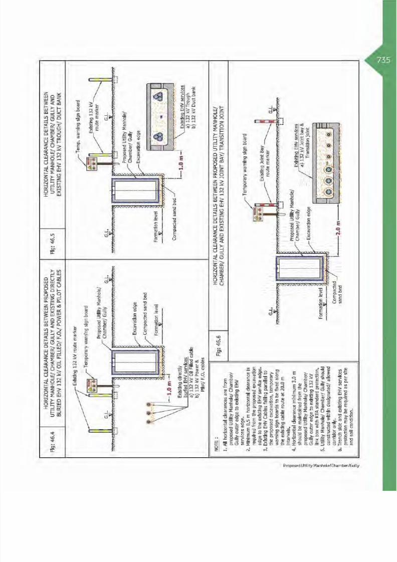
8/15/2019 Dewa Latest Reg 2014
http://slidepdf.com/reader/full/dewa-latest-reg-2014 759/817

8/15/2019 Dewa Latest Reg 2014
http://slidepdf.com/reader/full/dewa-latest-reg-2014 760/817

8/15/2019 Dewa Latest Reg 2014
http://slidepdf.com/reader/full/dewa-latest-reg-2014 761/817

8/15/2019 Dewa Latest Reg 2014
http://slidepdf.com/reader/full/dewa-latest-reg-2014 762/817

8/15/2019 Dewa Latest Reg 2014
http://slidepdf.com/reader/full/dewa-latest-reg-2014 763/817

8/15/2019 Dewa Latest Reg 2014
http://slidepdf.com/reader/full/dewa-latest-reg-2014 764/817

8/15/2019 Dewa Latest Reg 2014
http://slidepdf.com/reader/full/dewa-latest-reg-2014 765/817

8/15/2019 Dewa Latest Reg 2014
http://slidepdf.com/reader/full/dewa-latest-reg-2014 766/817

8/15/2019 Dewa Latest Reg 2014
http://slidepdf.com/reader/full/dewa-latest-reg-2014 767/817
743Table 2: Clearance & Protection details for proposed Loading, Unloading Material Machinery and
existing DEWA Electricity HV services
Electricity HV existing
Services
Horizontal
Clearance
Crossing DetailsRemarksVertical
Clearance
Crossing
Position
Crossing
Method
Standard
Protection
HV
(6.6/11/33 kV)
Power/Pilot Cable
and Joints 1.0 m NA
- - R
(Ref Fig: 47.2, Case 1)
HV
(6.6/11/33 kV) Manhole- - -
(Ref Fig: 47.2, Case 2)
HV
(6.6/11/33 kV) O.H.L.5.0 m NA - - R
(Ref Fig: 47.3)
Clearance & Protection details for access under Existing HV OHL
HV
(6.6/11 kV) O.H.L.
5.0 m
3.0 m
B - R
(Ref Fig: 47.3)
(Ref Fig: 47.3)
(Ref Fig: 47.3)
HV
(33 kV) O.H.L.3.5 m
Table Abbreviation
A - Above existing DEWA services. OC - Open Cut Method.
B - Below existing DEWA services. R - Required Protection.
A/B - Above or Below existing DEWA services. NR - Not required.
NDCM - Non Disruptive Crossing Method. NA - Not allowed.
Proposed Loading/Unloading materials and M achineries

8/15/2019 Dewa Latest Reg 2014
http://slidepdf.com/reader/full/dewa-latest-reg-2014 768/817
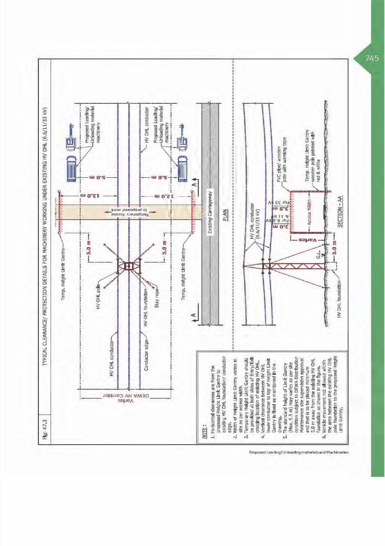
8/15/2019 Dewa Latest Reg 2014
http://slidepdf.com/reader/full/dewa-latest-reg-2014 769/817

8/15/2019 Dewa Latest Reg 2014
http://slidepdf.com/reader/full/dewa-latest-reg-2014 770/817
46Table 3: Clearance & Protection details for proposed Loading, Unloading Material Machinery and
existing DEWA Electricity EHV services
Electricity EHV
existing Services
Horizontal
Clearance
Crossing DetailsRemarksVertical
Clearance
Crossing
Position
Crossing
Method
Standard
Protection
EHV (132 kV)
Oil Filled Cable (O.F)2.0 m NA - - R
(Ref Fig: 47.4)
EHV (132 kV)
Power/Pilot/F.O Cable
(Directly Buried)
2.0 m NA - - R
(Ref Fig: 47.4)
EHV (132 kV) Trough 2.0 m NA - - R
(Ref Fig: 47.5)
EHV (132 kV)
Duct Bank2.0 m NA - - R
(Ref Fig: 47.5)
EHV (132 kV)
Joint Bay/
Transition Joint
3.0 m NA - - -
(Ref Fig: 47.6)
EHV (132/400 kV)
O.H.L5.0 m - B - R
(Ref Fig: 47.8)
EHV (400 kV) Tunnel 2.5 m NA - - R
(Ref Fig: 47.7)
Clearance & Protection details for access under Existing EHV OHL
EHV (132 kV) O.H.L
5.0 m
4.5 m
B - R
(Ref Fig: 47 .8)
(Ref Fig: 47.8)
(Ref Fig: 47.8)EHV (400 kV) O.H.L 7.5 m
Table Abbreviation
A - Above existing DEWA services. OC - Open Cut Method.
B - Below existing DEWA services. R - Required Protection.
A/B - Above or Below existing DEWA services. NR - Not required.
NDCM - Non Disruptive Crossing Method. NA - Not allowed.

8/15/2019 Dewa Latest Reg 2014
http://slidepdf.com/reader/full/dewa-latest-reg-2014 771/817
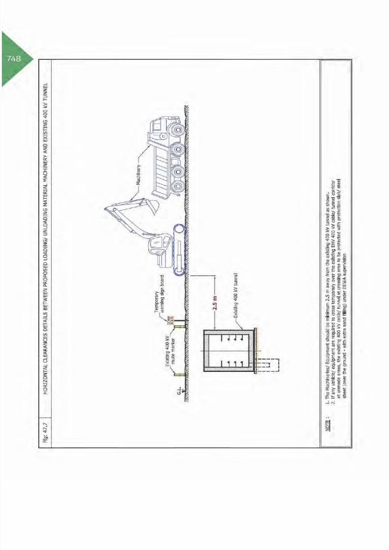
8/15/2019 Dewa Latest Reg 2014
http://slidepdf.com/reader/full/dewa-latest-reg-2014 772/817
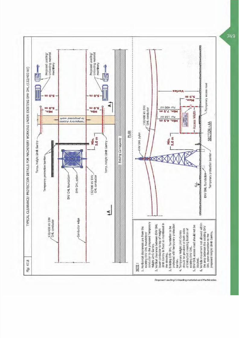
8/15/2019 Dewa Latest Reg 2014
http://slidepdf.com/reader/full/dewa-latest-reg-2014 773/817
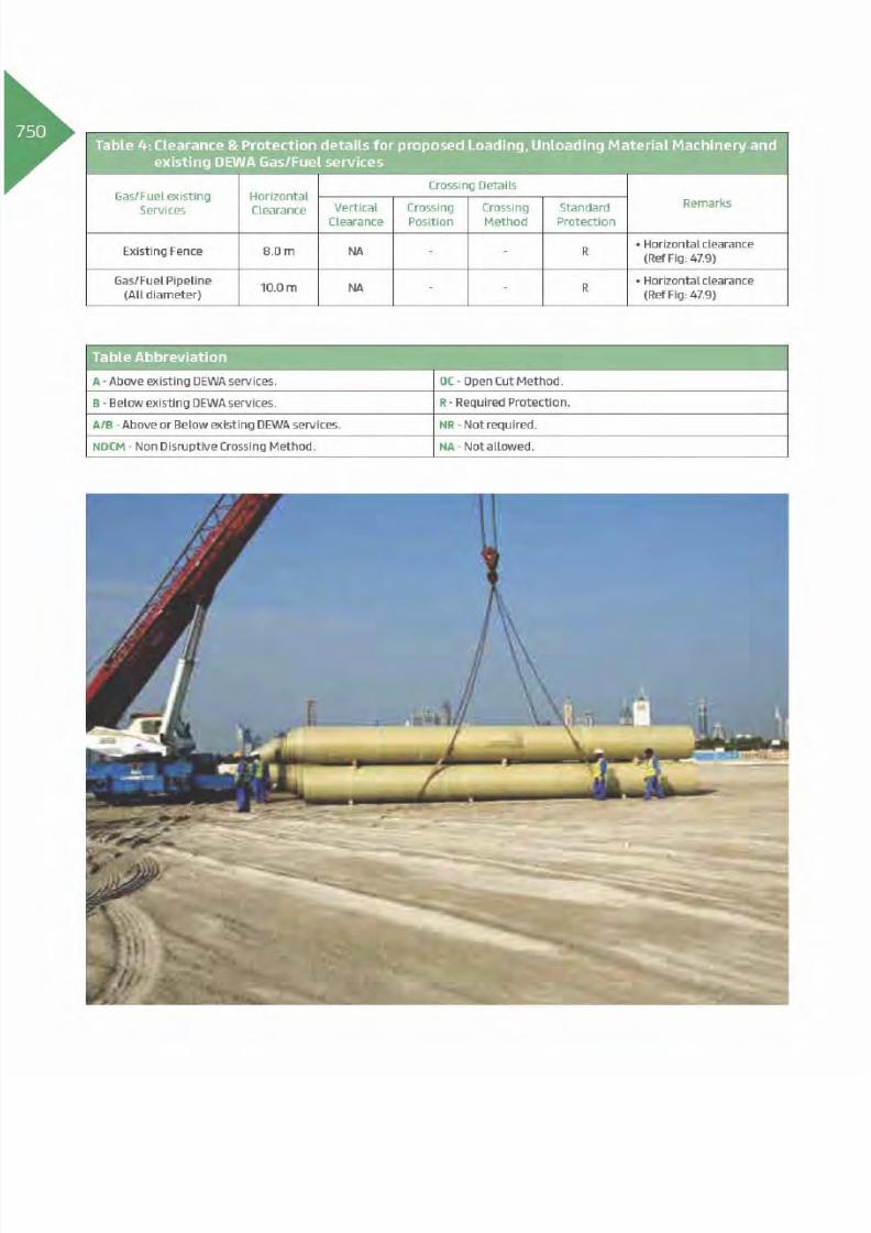
8/15/2019 Dewa Latest Reg 2014
http://slidepdf.com/reader/full/dewa-latest-reg-2014 774/817

8/15/2019 Dewa Latest Reg 2014
http://slidepdf.com/reader/full/dewa-latest-reg-2014 775/817

8/15/2019 Dewa Latest Reg 2014
http://slidepdf.com/reader/full/dewa-latest-reg-2014 776/817
5248. Removal of Existing Plants & Trees
48.1 Introduction
Removal of trees/plants could not be avoided insome circumstances, such as, when they obstructconstruction site, or when severely injured bystorms, or when they outgrow their sites, or hindermaintenance work of utilities/services, or when theymay have to be replanted in another location. Trees/plants removals must be carried out by specialised
agricultures using special equipment, tools andmachines under supervision of a specialist from theconcerned authority. During the removal processMachines could encroaching DEWA existing servicesand/or corridors therefore during this process itis required to protect DEWA existing assets as perspecified standards.

8/15/2019 Dewa Latest Reg 2014
http://slidepdf.com/reader/full/dewa-latest-reg-2014 777/817

8/15/2019 Dewa Latest Reg 2014
http://slidepdf.com/reader/full/dewa-latest-reg-2014 778/817

8/15/2019 Dewa Latest Reg 2014
http://slidepdf.com/reader/full/dewa-latest-reg-2014 779/817
755Table 2: Clearance & Protection details for proposed removal of Plants/Trees and existing DEWA
electricity HV services
Electricity HV existing
Services
Horizontal
Clearance
Crossing DetailsRemarksVertical
Clearance
Crossing
Position
Crossing
Method
Standard
Protection
HV
(6.6/11/33 kV)
Power/Pilot Cable
and Joints
1.0 m NR - - R
(Ref Fig: 48.2)
(Ref Fig: 48.2 )
HV
(6.6/11/33 kV)
Manhole
1.0 m NR - - R
(Ref Fig: 48.3)
HV
(6.6/11/33 kV)
O.H.L.
5.0 m NR - - R
(Ref Fig:48.4)
(Ref Fig: 48.4 )
Clearance & Protection details for access and working under Existing HV-OHL
HV
(6.6/11 kV) O.H.L.
5.0 m
3.0 m
B - R
(Ref Fig: 48.4)
(Ref Fig: 48.4 )
(Ref Fig: 48.4 )
HV
(33 kV) O.H.L.3.5 m
Table Abbreviation
A - Above existing DEWA services. OC - Open Cut Method.
B - Below existing DEWA services. R - Required Protection.
A/B - Above or Below existing DEWA services. NR - Not required.
NDCM - Non Disruptive Crossing Method. NA - Not allowed.
Removal of existing Plants & Trees

8/15/2019 Dewa Latest Reg 2014
http://slidepdf.com/reader/full/dewa-latest-reg-2014 780/817

8/15/2019 Dewa Latest Reg 2014
http://slidepdf.com/reader/full/dewa-latest-reg-2014 781/817

8/15/2019 Dewa Latest Reg 2014
http://slidepdf.com/reader/full/dewa-latest-reg-2014 782/817
58Table 3: Clearance & Protection details for proposed removal of Plants/Trees and existing DEWA
electricity EHV services
Electricity EHV
existing Services
Horizontal
Clearance
Crossing DetailsRemarksVertical
Clearance
Crossing
Position
Crossing
Method
Standard
Protection
EHV (132 kV)
Oil Filled Cable (O.F)1.0 m NR - - R
(Ref Fig:48.5)
(Ref Fig: 48.5 )
EHV (132 kV)
Power/Pilot/F.O Cable
(Directly Buried)
1.0 m NR - - R
(Ref Fig: 48.5 )
(Ref Fig: 48.5 )
EHV (132 kV) Trough 1.0 m NR - - R
(Ref Fig: 48.6 )
(Ref Fig: 48.6)
EHV (132 kV)
Duct Bank1.0 m NR - - R
(Ref Fig: 48.6 )
(Ref Fig: 48.6)
EHV (132 kV)
Joint Bay/
Transition Joint
2.0 m NR - - R
(Ref Fig: 48.7 )
EHV (132/400 kV)
O.H.LNR - - - - -
EHV (400 kV) Tunnel 2.5 m NR - - R
(Ref Fig: 48.8)
(Ref Fig: 48.8)
Clearance & Protection details for access and working under Existing EHV-OHL
EHV (132 kV) O.H.L
5.0 m
4.5 m
B - R
(Ref Fig: 48.9 )
(Ref Fig: 48.9 )
(Ref Fig: 48.9 )EHV (400 kV) O.H.L 7.5 m
Table Abbreviation
A - Above existing DEWA services. OC - Open Cut Method.
B - Below existing DEWA services. R - Required Protection.
A/B - Above or Below existing DEWA services. NR - Not required.
NDCM - Non Disruptive Crossing Method. NA - Not allowed.

8/15/2019 Dewa Latest Reg 2014
http://slidepdf.com/reader/full/dewa-latest-reg-2014 783/817

8/15/2019 Dewa Latest Reg 2014
http://slidepdf.com/reader/full/dewa-latest-reg-2014 784/817

8/15/2019 Dewa Latest Reg 2014
http://slidepdf.com/reader/full/dewa-latest-reg-2014 785/817

8/15/2019 Dewa Latest Reg 2014
http://slidepdf.com/reader/full/dewa-latest-reg-2014 786/817
62Table 4: Clearance & Protection details for proposed removal of Plants/Trees and existing DEWA
Gas/Fuel services
Gas/Fuel existing
Services
Horizontal
Clearance
Crossing DetailsRemarksVertical
Clearance
Crossing
Position
Crossing
Method
Standard
Protection
Existing Fence 8.0 m NR - - R
(Ref Fig: 48.10)
(Ref Fig: 48.10 )
Gas/Fuel Pipeline
(All diameter)10.0 m NR - - R
(Ref Fig: 48.10)
(Ref Fig: 48.10 )
Table Abbreviation
A - Above existing DEWA services. OC - Open Cut Method.
B - Below existing DEWA services. R - Required Protection.
A/B - Above or Below existing DEWA services. NR - Not required.
NDCM - Non Disruptive Crossing Method. NA - Not allowed.

8/15/2019 Dewa Latest Reg 2014
http://slidepdf.com/reader/full/dewa-latest-reg-2014 787/817

8/15/2019 Dewa Latest Reg 2014
http://slidepdf.com/reader/full/dewa-latest-reg-2014 788/817

8/15/2019 Dewa Latest Reg 2014
http://slidepdf.com/reader/full/dewa-latest-reg-2014 789/817

8/15/2019 Dewa Latest Reg 2014
http://slidepdf.com/reader/full/dewa-latest-reg-2014 790/817
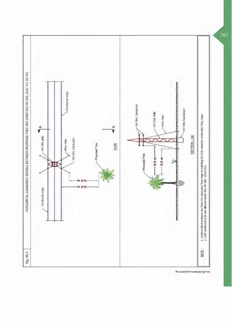
8/15/2019 Dewa Latest Reg 2014
http://slidepdf.com/reader/full/dewa-latest-reg-2014 791/817

8/15/2019 Dewa Latest Reg 2014
http://slidepdf.com/reader/full/dewa-latest-reg-2014 792/817
68Table 3: Clearance & Protection details for proposed Soft Landscaping/Tree and existing DEWA
Electricity EHV services
ElectricityEHV existing
Services
ProposedSoft
Landscaping/
Tree
Horizontal
Clearance
Crossing DetailsRemarksVertical
Clearance
Crossing
Position
Crossing
Method
Standard
Protection
EHV (132 kV)
Oil Filled Cable
(O.F)
Soft
LandscapingNR 1.0 m - - -
(Ref Fig:49.4)
Tree 5.0 m NA - - -
(Ref Fig:49.4)
EHV (132 kV)
Power/Pilot/
F.O Cable
(Directly Buried)
Soft
LandscapingNR 1.0 m - - -
(Ref Fig:49.4)
Tree 5.0 m NA - - -
(Ref Fig:49.4)
EHV (132 kV)
Trough
Soft
LandscapingNR 1.0 m - - -
(Ref Fig:49.5)
Tree 5.0 m NA - - -
(Ref Fig:49.5)
EHV (132 kV)
Duct Bank
Soft
LandscapingNR 1.0 m - - -
(Ref Fig:49.5)
Tree 5.0 m NA - - -
(Ref Fig:49.5)
EHV (132 kV)Joint Bay/
Transition Joint
Soft
LandscapingNA - - - - -
Tree 5.0 m NA - - -
(Ref Fig:49.6)
EHV (132 kV)
O.H.L
Soft
LandscapingNA - - - - -
Tree 15.0 m NA - -
(Ref Fig:49.7)
EHV (400 kV)
O.H.L
Soft
LandscapingNA - - - - -
Tree 20.0 m NA - - -
(Ref Fig:49.8)
EHV (400 kV)
Tunnel
Soft
LandscapingNR 1.0 m - - -
(Ref Fig:49.9)
Tree 5.0 m NA - - -
(Ref Fig:49.9)
Table Abbreviation
A - Above existing DEWA services. OC - Open Cut Method.
B - Below existing DEWA services. R - Required Protection.
A/B - Above or Below existing DEWA services. NR - Not required.
NDCM - Non Disruptive Crossing Method. NA - Not allowed.

8/15/2019 Dewa Latest Reg 2014
http://slidepdf.com/reader/full/dewa-latest-reg-2014 793/817

8/15/2019 Dewa Latest Reg 2014
http://slidepdf.com/reader/full/dewa-latest-reg-2014 794/817

8/15/2019 Dewa Latest Reg 2014
http://slidepdf.com/reader/full/dewa-latest-reg-2014 795/817

8/15/2019 Dewa Latest Reg 2014
http://slidepdf.com/reader/full/dewa-latest-reg-2014 796/817

8/15/2019 Dewa Latest Reg 2014
http://slidepdf.com/reader/full/dewa-latest-reg-2014 797/817

8/15/2019 Dewa Latest Reg 2014
http://slidepdf.com/reader/full/dewa-latest-reg-2014 798/817

8/15/2019 Dewa Latest Reg 2014
http://slidepdf.com/reader/full/dewa-latest-reg-2014 799/817

8/15/2019 Dewa Latest Reg 2014
http://slidepdf.com/reader/full/dewa-latest-reg-2014 800/817

8/15/2019 Dewa Latest Reg 2014
http://slidepdf.com/reader/full/dewa-latest-reg-2014 801/817

8/15/2019 Dewa Latest Reg 2014
http://slidepdf.com/reader/full/dewa-latest-reg-2014 802/817

8/15/2019 Dewa Latest Reg 2014
http://slidepdf.com/reader/full/dewa-latest-reg-2014 803/817

8/15/2019 Dewa Latest Reg 2014
http://slidepdf.com/reader/full/dewa-latest-reg-2014 804/817
80Table 3: Clearance & Protection details for proposed Hard Landscaping and existing DEWA
Electricity EHV services
Electricity EHV
existing Services
Proposed Hard
Landscaping
Horizontal
Clearance
Crossing DetailsRemarksVertical
Clearance
Crossing
Position
Crossing
Method
Standard
Protection
EHV (132 kV)
Oil Filled Cable
(O.F)
Interlock Tiles NR 1.0 m - - -
(Ref Fig:50.4)
Stones, Granite,
Concrete, etc1.0 m NA - - -
(Ref Fig:50.4)
EHV (132 kV)
Power/Pilot/
F.O Cable
(Directly Buried)
Interlock Tiles NR 1.0 m - - -
(Ref Fig:50.4)
Stones, Granite,
Concrete, etc
1.0 m NA - - -
(Ref Fig:50.4)
EHV (132 kV)
Trough
Interlock Tiles NR 1.0 m - - -
(Ref Fig:50.5)
Stones, Granite,
Concrete, etc1.0 m NA - - -
(Ref Fig:50.5)
EHV (132 kV)
Duct Bank
Interlock Tiles NR 1.0 m - - -
(Ref Fig:50.5)
Stones, Granite,
Concrete, etc1.0 m NA - - -
(Ref Fig:50.5)
EHV (132 kV)
Joint Bay/
Transition Joint
Interlock Tiles NA - - - - -
Stones, Granite,
Concrete, etc1.0 m NA - - -
(Ref Fig:50.6)
EHV (132 kV)
O.H.L
Interlock Tiles NA - - - - -
Stones, Granite,
Concrete, etc1.0 m NA -
(Ref Fig:50.7)
EHV (400 kV)
O.H.L
Interlock Tiles NA - - - - -
Stones, Granite,
Concrete, etc1.0 m NA - - -
(Ref Fig:50.8)
EHV (400 kV)
Tunnel
Interlock Tiles NR 1.0 m - - -
(Ref Fig:50.9)
Stones, Granite,
Concrete, etc2.5 m NA - - -
(Ref Fig:50.9)
Table Abbreviation
A - Above existing DEWA services. OC - Open Cut Method.
B - Below existing DEWA services. R - Required Protection.
A/B - Above or Below existing DEWA services. NR - Not required.NDCM - Non Disruptive Crossing Method. NA - Not allowed.

8/15/2019 Dewa Latest Reg 2014
http://slidepdf.com/reader/full/dewa-latest-reg-2014 805/817

8/15/2019 Dewa Latest Reg 2014
http://slidepdf.com/reader/full/dewa-latest-reg-2014 806/817
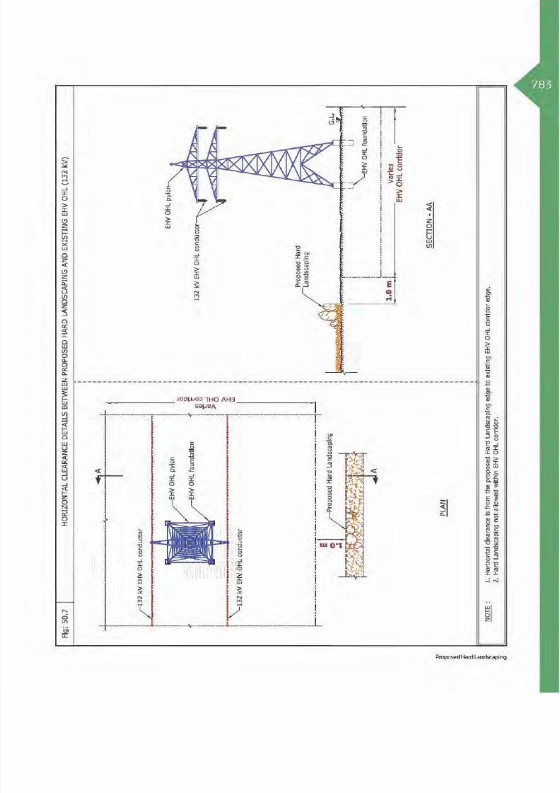
8/15/2019 Dewa Latest Reg 2014
http://slidepdf.com/reader/full/dewa-latest-reg-2014 807/817

8/15/2019 Dewa Latest Reg 2014
http://slidepdf.com/reader/full/dewa-latest-reg-2014 808/817

8/15/2019 Dewa Latest Reg 2014
http://slidepdf.com/reader/full/dewa-latest-reg-2014 809/817

8/15/2019 Dewa Latest Reg 2014
http://slidepdf.com/reader/full/dewa-latest-reg-2014 810/817

8/15/2019 Dewa Latest Reg 2014
http://slidepdf.com/reader/full/dewa-latest-reg-2014 811/817

8/15/2019 Dewa Latest Reg 2014
http://slidepdf.com/reader/full/dewa-latest-reg-2014 812/817
88

8/15/2019 Dewa Latest Reg 2014
http://slidepdf.com/reader/full/dewa-latest-reg-2014 813/817
789
ACRONYMSS No Abbreviations Expansion
1 AC Pipe Asbestos Cement Pipe
2 CPT Cone Penetration Test3 DEWA Dubai Electricity & Water Authority
4 Dia Diameter
5 EHV Extra High Voltage
6 FGL Finish Ground Level
7 Fig Figure
8 F.O Fiber optic
9 FRL Finish Road Level
10 GI Galvanized Iron
11 GL Ground level
12 GRE Glass Reinforced Epoxy
13 GRP Glass Reinforced Pipes
14 HDD Horizontal Directional Drilling
15 HDPE High-Density Poly Ethylene
16 HV High Voltage
17 HL Horizontal
18 I/H Beam I or H shape beam
19 I D Internal Diameter
20 kV Kilovolt
21 LV Low Voltage
22 m Meter
23 Max Maximum
24 Min Minimum
25 mm Millimeter
26 NDCM Non-Disruptive Crossing Method
27 NDRC Non-Disruptive Road Crossing
28 NOC No Objection Certificate
29 Ø Diameter
30 OHL Over Head Line
31 O.F Oil Filled
32 OPGW Optical Ground Wire
33 PPV Peak Particle Velocity
34 Ref Refer to
35 RCC Reinforced Cement Concrete
36 ROW Right Of Way
37 RTA Road & Transportation Authority
38 SCADA Supervisory Control and Data Acquisition
39 Temp. Temporary
40 uPVC Unplasticized polyvinyl chloride
41 VL Vertical
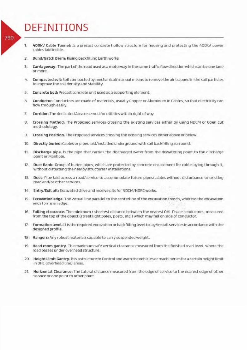
8/15/2019 Dewa Latest Reg 2014
http://slidepdf.com/reader/full/dewa-latest-reg-2014 814/817

8/15/2019 Dewa Latest Reg 2014
http://slidepdf.com/reader/full/dewa-latest-reg-2014 815/817
791
22. Hump: Small mounted projection rising above the existing ground/road level.
23. HV Manhole: Access chamber for making connections and maintenance for buried HV cables under the road.
24. I/H Beam: I-Beam shape or H-beam shaped is a steel element, used as a supporting element.
25. Joint Bay for Transmission Cable Joints: A concrete structure with cover to accommodate and protect 132 kVcable joints
26. Link Box: It is a box like enclosure equipped with disconnecting/ isolating links, used in the transmissioncable system, for bonding and grounding the metallic screen/ sheath of power transmission cables.
27. Manual excavation: It is the excavation activity carried out by hand tools only and without the use of anymechanical machines/equipment.
28. Oil Field cable: It is a cable insulated with Oil and paper.
29. OPGW: Optical Ground Wire is a combination of Fiber optic cables (inside) for communication purpose, andground wire (outside) – for lightening protection, used in HV and EHV overhead power transmission lines.
30. Overhead Line: One or more power transmission lines (conductors) stringed/ suspended above the ground byinsulators on towers/ Pylons or utility poles.
31. Pile Cap: It is a structure element consists of mass concrete mat connecting group of piles/single piletop portion
32. Pilot cable: It is a copper cable laid for cable route identification, which helps to indicate the presence of
Transmission cable(s) underneath the subject area.
33. Pipeline joint: It is the assembly of two pipes or fittings or pipe and fitting by electrical or mechanical meansto form a flexible or rigid joint
34. Pole: It is a Steel or wooden post used to support an Overhead HV power line
35. Power Cable: An assembly of one or more electrical conductors covered with sheath used for transmission ofelectrical power.
36. Protection Slab: A flat reinforced concrete structure element, used to protect the existing services.
37. Pylon: It is a Steel lattice structure /tower used to support an Overhead power transmission lines.
38. Route marker: Standard visible markers installed on the services route to indicate the existing services.
39. Settlement Calculation: An accurate estimate of soil settlement.
40. Sheet Pile: It is always steel sheet structure to support the soil during the excavation
41. Shoulder line: It is the yellow line that defines the portion of pavement continuous with the travelled way foraccommodation of stopped vehicles for emergency use.
42. Soft material: Any compressive material that can separate two different elements without showing impacton the contacted materials
43. Spare Duct: An additional pipe/duct placed for future use.
44. Split Duct: A longitudinally split/cut pipe used to protect existing cable/pipe always surrounded with concrete.

8/15/2019 Dewa Latest Reg 2014
http://slidepdf.com/reader/full/dewa-latest-reg-2014 816/817
8/15/2019 Dewa Latest Reg 2014
http://slidepdf.com/reader/full/dewa-latest-reg-2014 817/817
793Infrastructure NOC Technical Manual references
REFERENCES