
DeviceNet Slave Protocol API - hilscher.com · DeviceNet Slave | Protocol API DOC060202API13EN |...
142
Protocol API DeviceNet Slave V2.3.x.x Hilscher Gesellschaft für Systemautomation mbH www.hilscher.com DOC060202API13EN | Revision 13 | English | 2013-12 | Released | Public
Transcript of DeviceNet Slave Protocol API - hilscher.com · DeviceNet Slave | Protocol API DOC060202API13EN |...

Protocol API
DeviceNet Slave
V2.3.x.x
Hilscher Gesellschaft für Systemautomation mbH
www.hilscher.com DOC060202API13EN | Revision 13 | English | 2013-12 | Released | Public

Introduction 2/142
DeviceNet Slave | Protocol API DOC060202API13EN | Revision 13 | English | 2013-12 | Released | Public © Hilscher, 2006-2013
Table of Contents
1 Introduction.............................................................................................................................................7 1.1 Abstract ..........................................................................................................................................7 1.2 List of Revisions .............................................................................................................................7 1.3 System Requirements....................................................................................................................9 1.4 Intended Audience .........................................................................................................................9 1.5 Specifications ...............................................................................................................................10
1.5.1 Technical Data ................................................................................................................................ 10 1.5.2 Object Modeling .............................................................................................................................. 11
1.6 Terms, Abbreviations, Definitions ................................................................................................15 1.7 References...................................................................................................................................15 1.8 Legal Notes ..................................................................................................................................16
1.8.1 Copyright ......................................................................................................................................... 16 1.8.2 Important Notes............................................................................................................................... 16 1.8.3 Exclusion of Liability ........................................................................................................................ 17 1.8.4 Export .............................................................................................................................................. 17
2 Fundamentals .......................................................................................................................................18 2.1 General Access Mechanisms on netX Systems ..........................................................................18 2.2 Accessing the Protocol Stack by Programming the AP Task’s Queue........................................19
2.2.1 Getting the Receiver Task Handle of the Process Queue ............................................................... 19 2.2.2 Meaning of Source- and Destination-related Parameters................................................................ 19
2.3 Accessing the Protocol Stack via the Dual Port Memory Interface..............................................20 2.3.1 Communication via Mailboxes......................................................................................................... 20 2.3.2 Using Source and Destination Variables correctly........................................................................... 21 2.3.3 Obtaining useful Information about the Communication Channel.................................................... 24
2.4 Client/Server Mechanism.............................................................................................................26 2.4.1 Application as Client ........................................................................................................................ 26 2.4.2 Application as Server ...................................................................................................................... 27
3 Dual-Port Memory ................................................................................................................................28 3.1 Cyclic Data (Input/Output Data) ...................................................................................................28
3.1.1 Input Process Data.......................................................................................................................... 29 3.1.2 Output Process Data ....................................................................................................................... 29
3.2 Acyclic Data (Mailboxes)..............................................................................................................30 3.2.1 General Structure of Messages or Packets for Non-Cyclic Data Exchange .................................... 31 3.2.2 Status & Error Codes ...................................................................................................................... 34 3.2.3 Differences between System and Channel Mailboxes .................................................................... 34 3.2.4 Send Mailbox................................................................................................................................... 35 3.2.5 Receive Mailbox .............................................................................................................................. 35 3.2.6 Channel Mailboxes (Details of Send and Receive Mailboxes) ........................................................ 35
3.3 Status ...........................................................................................................................................37 3.3.1 Common Status............................................................................................................................... 37 3.3.2 Extended Status .............................................................................................................................. 43
3.4 Control Block................................................................................................................................45
4 Getting started/Configuration .............................................................................................................46 4.1 Overview about Essential Functionality .......................................................................................46 4.2 Configuration Procedures ............................................................................................................46
4.2.1 Using a Packet ................................................................................................................................ 46 4.3 Warmstart Parameters .................................................................................................................47
4.3.1 Behavior when receiving a Set Configuration / Warmstart Command............................................. 53 4.4 Process Data (Input and Output) .................................................................................................53 4.5 Task Structure of the DeviceNet Slave Stack ..............................................................................54
5 The User Application Interface ...........................................................................................................55 5.1 The Dual Port Memory Interface..................................................................................................55 5.2 The AP-Task ................................................................................................................................56
5.2.1 DNSAP_STARTUPPARAMETER_T – Startup Parameter for Stack App Task..................................... 57 5.2.2 DNS_AP_CMD_SET_CONFIGURATION_REQ/CNF – Set Configuration............................................ 58
5.3 The DNS-Task .............................................................................................................................65 5.3.1 DNS_FAL_CMD_APP_REQ/CNF – Register Application with DeviceNet Stack ............................... 67 5.3.2 DNS_FAL_CMD_INIT_STACK_REQ/CNF – Init Stack ..................................................................... 71 5.3.3 DNS_FAL_CMD_SET_INPUT_REQ/CNF – Set DeviceNet Slave Input Image ................................ 76
Introduction 3/142
DeviceNet Slave | Protocol API DOC060202API13EN | Revision 13 | English | 2013-12 | Released | Public © Hilscher, 2006-2013
5.3.4 DNS_FAL_CMD_GET_OUTPUT_REQ/CNF – Get DeviceNet Slave Output Image ........................... 79 5.3.5 DNS_FAL_CMD_UPDATE_IO_REQ/CNF – Update DeviceNet Slave I/O Image ............................. 82 5.3.6 DNS_FAL_CMD_GET_SET_ATT_IND/INDRET – Get/Set Attribute Indication................................ 86 5.3.7 DNS_FAL_CMD_GET_SET_ATT_RES/RESRET – Get/Set Attribute Response............................... 90 5.3.8 DNS_FAL_CMD_GET_STATUS_REQ/CNF – Get DeviceNet Slave Task Status.............................. 96 5.3.9 DNS_FAL_CMD_SET_MODE_REQ/CNF – Set Mode Request......................................................... 101 5.3.10 DNS_FAL_CMD_CLR_CONFIG_REQ/CNF – Clear Configuration Request ..................................... 104 5.3.11 DNS_FAL_CMD_LED_STATE_IND – LED State Indication ............................................................ 106 5.3.12 DNS_FAL_CMD_UPDATE_IO_IND – IO Update Indication ............................................................ 109 5.3.13 DNS_FAL_CMD_REGISTER_CLASS_REQ – Register Class........................................................... 112 5.3.14 DNS_FAL_CMD_UNREGISTER_CLASS_REQ – Unregister Class ................................................... 115 5.3.15 DNS_FAL_CMD_REMOTE_SERVICE_IND/RES – Remote Service............................................... 117 5.3.16 DNS_FAL_CMD_SERVICE_REQ/CNF –Service ............................................................................ 123
5.4 Hardware Switches for the Adjustment of Slave Address and Baudrate...................................131 5.4.1 RCX_SET_HW_SWITCH_VALUES_REQ/CNF – Set the values of the Hardware Switch ................. 133
6 Status/Error Codes Overview............................................................................................................136 6.1 Error Codes of the FAL-Task .....................................................................................................136 6.2 Error Codes of the AP-Task.......................................................................................................139 6.3 Error Codes of the CAN_DL-Task .............................................................................................140
7 Contacts ..............................................................................................................................................142
Introduction 4/142
DeviceNet Slave | Protocol API DOC060202API13EN | Revision 13 | English | 2013-12 | Released | Public © Hilscher, 2006-2013
List of Figures
Figure 1: The 3 different Ways to access a Protocol Stack running on a netX System..................................................... 18 Figure 2: Use of ulDest in Channel and System Mailbox................................................................................................ 21 Figure 3: Using ulSrc and ulSrcId ............................................................................................................................... 22 Figure 4: Start-up Process .............................................................................................................................................. 132

Introduction 5/142
DeviceNet Slave | Protocol API DOC060202API13EN | Revision 13 | English | 2013-12 | Released | Public © Hilscher, 2006-2013
List of Tables
Table 1: List of Revisions .................................................................................................................................................... 8 Table 2: Identity Object Supported Features..................................................................................................................... 11 Table 3: DeviceNet Object Supported Features................................................................................................................ 12 Table 4: Connection Object Supported Features .............................................................................................................. 13 Table 5: Acknowledge Handler Object Supported Features ............................................................................................. 14 Table 6: Terms, Abbreviations and Definitions.................................................................................................................. 15 Table 7: References.......................................................................................................................................................... 15 Table 8: Queue Names used in DeviceNet Slave ............................................................................................................. 19 Table 9: The Meaning of the Source- and Destination-related Parameters ...................................................................... 19 Table 10: Use of Destination Identifier ulDest ................................................................................................................ 21 Table 11: Input Data Image (Default Size) ........................................................................................................................ 29 Table 12: Input Data Image for netX devices with 8 kByte Dual-port Memory .................................................................. 29 Table 13: Output Data Image (Default size) ...................................................................................................................... 29 Table 14: Output Data Image for netX devices with 8 kByte Dual-port Memory................................................................ 29 Table 15: General Structure of Packets for non-cyclic Data Exchange............................................................................. 31 Table 16: Channel Mailboxes............................................................................................................................................ 35 Table 17: Common Status Structure Definition ................................................................................................................. 38 Table 18: Communication State of Change....................................................................................................................... 39 Table 19: Meaning of Communication Change of State Flags .......................................................................................... 40 Table 20: Extended Status Block ...................................................................................................................................... 43 Table 21: Overview about essential Functionality (Cyclic and acyclic Data Transfer and Alarm Handling). ..................... 46 Table 22: Meaning and allowed Values for Warmstart-Parameters. ................................................................................. 48 Table 23: Available Baud Rate Values.............................................................................................................................. 49 Table 24: Meaning of ConfigFlags Byte ............................................................................................................................ 50 Table 25: Meaning of EnableFlags Byte ........................................................................................................................... 52 Table 26: Input and Output Data ....................................................................................................................................... 53 Table 27: DNS-Task Process Queue ................................................................................................................................ 56 Table 28: Overview over the Packets of the DeviceNet Slave AP -Task of the DeviceNet Slave Protocol Stack ............. 56 Table 29: Structure DNSAP_STARTUPPARAMETER_T ................................................................................................. 57 Table 30: DNS_AP_CMD_SET_CONFIGURATION_REQ – Request Command for DNS Stack Configuration ..................... 62 Table 31: DNS_AP_CMD_SET_CONFIGURATION_CNF – Confirmation of DNS Stack Initialization ................................... 64 Table 32: DNS-Task Process Queue ................................................................................................................................ 65 Table 33: Overview over the Packets of the DeviceNet Slave -Task of the DeviceNet Slave Protocol Stack ................... 66 Table 34: DNS_FAL_CMD_REG_APP_REQ – Request Command for DNS Get Status....................................................... 68 Table 35: DNS_FAL_CMD_REG_APP_REQ – Packet Status/Error..................................................................................... 68 Table 36: DNS_FAL_CMD_REG_APP_CNF – Confirmation of DNS Get Status .................................................................. 70 Table 37: DNS_FAL_CMD_REG_APP_CNF – Packet Status/Error ...................................................................................... 70 Table 38: DNS_FAL_CMD_INIT_STACK_REQ – Request Command for DNS Stack Initialization .................................... 74 Table 39: DNS_FAL_CMD_INIT_STACK_CNF – Confirmation Command for DNS Stack Initialization ............................. 75 Table 40: DNS_FAL_CMD_SET_INPUT_REQ – Request Command for Set Input Image Update ...................................... 77 Table 41: DNS_FAL_CMD_SET_INPUT_CNF – Confirmation of the DNS Set Input Image Update ................................... 78 Table 42: Data Status of Produced/ Consumed Data ....................................................................................................... 79 Table 43: DNS_FAL_CMD_GET_OUTPUT_REQ – Request Command for Get Output Image ............................................. 80 Table 44: DNS_FAL_CMD_GET_OUTPUT_CNF – Confirmation of the DNS Get Output Image .......................................... 81 Table 45: Data Status of Produced/ Consumed Data (Allowed Values for ulOutDataSta) ........................................... 82 Table 46: DNS_FAL_CMD_UPDATE_IO_REQ – Request Command for I/O Image Update ............................................... 83 Table 47: DNS_FAL_CMD_UPDATE_IO_CNF – Confirmation of the DNS I/O Image Update............................................. 85 Table 48: Allowed Values of bFunction Parameter........................................................................................................ 86 Table 49: DNS_FAL_CMD_GET_SET_ATT_IND – Indication of Get/Set Attribute Event.................................................... 88 Table 50: DNS_FAL_CMD_GET_SET_ATT_IND – Indication of Get/Set Attribute Event.................................................... 89 Table 51: bFunction Parameter......................................................................................................................................... 90 Table 52: DNS_FAL_CMD_GET_SET_ATT_RES – bGenErrCode General Error Codes ................................................ 91 Table 53: DNS_FAL_CMD_GET_SET_ATT_RES – Get/Set Attribute Response................................................................. 93 Table 54: DNS_FAL_CMD_GET_SET_ATT_RESRET – Get/Set Attribute Response Return............................................... 95 Table 55: DNS_FAL_CMD_GET_STATUS_REQ – Request Command for DNS Get Status ................................................ 97 Table 56: DNS_FAL_CMD_GET_STATUS_CNF – Confirmation of DNS Get Status.......................................................... 100 Table 57: DeviceNet Operation Modes ........................................................................................................................... 101 Table 58: DNS_FAL_CMD_SET_MODE_REQ – Request Command for Setting Operation Mode..................................... 102 Table 59: DNS_FAL_CMD_SET_MODE_CNF – Request Command for Setting Operation Mode ...................................... 103 Table 60: DNS_FAL_CMD_CLR_CONFIG_REQ - Clear Configuration Request ................................................................ 104 Table 61: DNS_FAL_CMD_CLR_CONFIG_CNF – Confirmation of Clear Configuration Request ...................................... 105 Table 62: Meaning of ulLedType .................................................................................................................................. 106 Table 63: Meaning of ulLedMode .................................................................................................................................. 106 Table 64: Meaning of ulLedColor ................................................................................................................................ 106

Introduction 6/142
DeviceNet Slave | Protocol API DOC060202API13EN | Revision 13 | English | 2013-12 | Released | Public © Hilscher, 2006-2013
Table 65: DNS_FAL_CMD_LED_STATE_IND – LED State Indication .............................................................................. 107 Table 66: DNS_FAL_CMD_LED_STATE_RES – LED State Response ............................................................................. 108 Table 67: DNS_FAL_CMD_UPDATE_IO_IND – Update IO Indication ............................................................................. 110 Table 68: DNS_FAL_CMD_UPDATE_IO_RES – UPDATE IO Response ......................................................................... 111 Table 69: DNS_FAL_CMD_REGISTER_CLASS_REQ – Register a DeviceNet Class ........................................................ 113 Table 70: DNS_FAL_CMD_REGISTER_CLASS_RES – Register Class Response........................................................... 114 Table 71: DNS_FAL_CMD_UNREGISTER_CLASS_REQ – Unregister a DeviceNet Class................................................. 115 Table 72: DNS_FAL_CMD_UNREGISTER_CLASS_RES – Unregister Class Response ................................................... 116 Table 73: Service Codes according to the CIP Specification .......................................................................................... 117 Table 74: Generic Error (Variable bGenErr) .................................................................................................................. 118 Table 75: Additional Error (Variable bAddErr) ................................................................................................................. 118 Table 76: DNS_FAL_CMD_REMOTE_SERVICE_IND – Remote Service Request ...................................................... 119 Table 77: DNS_FAL_CMD_REMOTE_SERVICE_RES – Response to Remote Service Request ................................. 121 Table 78: Service Codes according to the CIP Specification .......................................................................................... 123 Table 79: Generic Error (Variable bGenErr) .................................................................................................................. 124 Table 80: Additional Error (Variable bAddErr) ................................................................................................................. 125 Table 81: Predefined Values for the Class ID according to the CIP Specification........................................................... 125 Table 82: Predefined Values for the Instance ID according to the DeviceNet Specification............................................ 126 Table 83: DNS_FAL_PACKET_SERVICE_REQ_T - Remote Service Request ............................................................. 128 Table 84: DNS_FAL_PACKET_SERVICE_CNF_T - Confirmation to Remote Service Request..................................... 130 Table 85: tSwitchValue – Structure of Switch Value set............................................................................................. 133 Table 86: RCX_SET_HW_SWITCH_VALUES_REQ_T – Set Hardware Switch Values Request ........................................ 134 Table 87: RCX_SET_HW_SWITCH_VALUES_CNF – Confirmation to Set Hardware Switch Values Request ................... 135 Table 88: Error Codes of the FAL-Task .......................................................................................................................... 138 Table 89: Error Codes of the AP-Task ............................................................................................................................ 139 Table 90: Error Codes of the CAN_DL-Task ................................................................................................................... 141

Introduction 7/142
DeviceNet Slave | Protocol API DOC060202API13EN | Revision 13 | English | 2013-12 | Released | Public © Hilscher, 2006-2013
1 Introduction
1.1 Abstract
This manual describes the application interface of the DeviceNet-Slave stack for netX products. The goal of this manual is to support the developer during the integration process of the given stack into a user Application.
This stack is based on the Hilscher Task Layer Reference Programming Model. It is a description of how to program a task in general, which is defined as a combination of appropriate functions belonging to the same type of protocol layer. It furthermore defines of how different tasks have to communicate with each other in order to exchange their layer information in between. The Reference Model is commonly used by all programmers at Hilscher and shall be used by you as well when writing your application task on top of the stack.
1.2 List of Revisions Rev Date Name Revisions
9 2010-10-28 RG/GG/MT/ET/TT
Firmware / stack version V2.3.0.x
- Added description of new packet DNS_FAL_CMD_REMOTE_SERVICE_IND/RES – Remote Service
- SetAttributeSingle service in DeviceNet object now supported.
- Description of 3 new ConfigFlags (see Table 24)
- Error Correction: DNS_FAL_PACKET_INIT_STACK_CNF_T has two parameters.
- Clarification of prerequisites for receiving indications in DNS_FAL_CMD_GET_SET_ATT_IND/INDRET – Get/Set Attribute Indication
- Clarifications in DNS_FAL_CMD_GET_SET_ATT_RES/RESRET – Get/Set Attribute Response
- Change of packet data in DNS_FAL_PACKET_REGISTER_CLASS_CNF_T packet
- Change of packet data in DNS_FAL_PACKET_UNREGISTER_CLASS_CNF_T packet
- Error corrections in subsections DNS_FAL_CMD_GET_SET_ATT_IND/INDRET – Get/Set Attribute Indication and DNS_FAL_CMD_GET_SET_ATT_RES/RESRET – Get/Set Attribute Response.

Introduction 8/142
DeviceNet Slave | Protocol API DOC060202API13EN | Revision 13 | English | 2013-12 | Released | Public © Hilscher, 2006-2013
Rev Date Name Revisions
10 2011-12-14 RG Firmware / stack version V2.3.7.x Reference to netX Dual-Port Memory Interface Manual Revision 12.
Added section 5.4“Hardware Switches for the Adjustment of Slave Address and Baudrate”
Added section 5.3.16 “DNS_FAL_CMD_SERVICE_REQ/CNF –Service”
Added flags for address and baudrate switches to the description of the System flags in sections 4.3 “Warmstart Parameters” and 5.2.2 “DNS_AP_CMD_SET_CONFIGURATION_REQ/CNF – Set Configuration”
Corrected wrong command code of DNS_FAL_CMD_GET_SET_ATT_RESRET in Table 53: DNS_FAL_CMD_GET_SET_ATT_RES – Get/Set Attribute Response
Added missing command codes for DNS_FAL_CMD_GET_SET_ATT_INDRET and DNS_FAL_CMD_GET_SET_ATT_RESRET to Table 33: Overview over the Packets of the DeviceNet Slave -Task of the DeviceNet Slave Protocol Stack
Added new packet – see section 5.3.16 “DNS_FAL_CMD_SERVICE_REQ/CNF –Service”
Added description of flag MSK_DNS_STA_FLAG_RX_IDLE in section DNS_FAL_CMD_GET_STATUS_REQ/CNF – Get DeviceNet Slave Task Status
Get Attribute All service now supported for Instance Attributes of Identity Object
Adapted section “Cyclic Data (Input/Output Data)” for netX devices with 8 kByte Dual-port Memory
Update of “Contacts” chapter
11 2012-11-14 RG Firmware / stack version V2.3.16.x Reference to netX Dual-Port Memory Interface Manual Revision 12.
Sections “DNS_AP_CMD_SET_CONFIGURATION_REQ/CNF – Set Configuration” and “DNS_FAL_CMD_INIT_STACK_REQ/CNF – Init Stack” have been corrected and clarified
Order of parameters corrected for DNS_FAL_GET_SET_ATT_IND_T.
Flag MSK_DNS_CFG_FLAG_IGNORE_ADDR_SWITCH no more active since version 2.3.8
Added information on baud rate coding
Corrected error description of TLR_E_DNS_FAL_BUS_OFF_STATE
Wrong range of values stated for the Watchdog Time has been corrected twice.
Removed wrong references
Some corrections in sections “Behavior when receiving a Set Configuration / Warmstart Command”^and “DNS_AP_CMD_SET_CONFIGURATION_REQ/CNF – Set Configuration”
Added some error message descriptions
12 2013-03-21 RG Firmware / stack version V2.3.19.x Reference to netX Dual-Port Memory Interface Manual Revision 12.
Changed section 1.5.2.3“DeviceNet Object (Class Code: 0x03)”
Added new parameter ulInfo to DNS_FAL_CMD_SET_MODE_REQ and DNS_FAL_CMD_SET_MODE_CNF Structures
13 2013-12-09 RG Firmware / stack version V2.3.23.x Reference to netX Dual-Port Memory Interface Manual Revision 12.
Error correction in section “Hardware Switches for the Adjustment of Slave Address and Baudrate”: 2 wrong flag names in paragraph “Enabling and disabling Address and Baudrate Switching” corrected.
Technical data: Now netX51/52 support present
Table 1: List of Revisions

Introduction 9/142
DeviceNet Slave | Protocol API DOC060202API13EN | Revision 13 | English | 2013-12 | Released | Public © Hilscher, 2006-2013
1.3 System Requirements
This software package has the following system requirements:
netX-Chip as CPU hardware platform
operating system for task scheduling required
1.4 Intended Audience
This manual is suitable for software developers with the following background:
Knowledge of the programming language C
Knowledge of the use of the real-time operating system rcX
Knowledge of the Hilscher Task Layer Reference Model

Introduction 10/142
DeviceNet Slave | Protocol API DOC060202API13EN | Revision 13 | English | 2013-12 | Released | Public © Hilscher, 2006-2013
1.5 Specifications
The data below applies to DeviceNet Slave firmware and stack version V2.3.x.x.
1.5.1 Technical Data
Maximum number of cyclic input data 255 bytes
Maximum number of cyclic output data 255 bytes
Acyclic communication Get_Attribute_Single/All max. 240 bytes per request
Set_Attribute_Single/All max. 240 bytes per request
Baud rates 125 kBits/s, 250 kBit/s, 500 kBit/s Auto-detection mode is not supported.
Connections Poll Change-of-state Cyclic Bit-strobe
Explicit messaging supported
Fragmentation Explicit and I/O
UCMM not supported
Firmware/stack available for netX
netX 50 yes
netX 51 yes
netX 52 yes
netX 100, netX 500 yes
PCI
DMA Support for PCI targets yes
Slot Number
Slot number supported for CIFX 50-DN
Configuration
Configuration by packet to transfer configuration parameters.
Diagnostic
Firmware supports common diagnostic in the dual-port-memory for loadable firmware.

Introduction 11/142
DeviceNet Slave | Protocol API DOC060202API13EN | Revision 13 | English | 2013-12 | Released | Public © Hilscher, 2006-2013
1.5.2 Object Modeling
The device is modeled as a collection of objects. Object modeling organizes related data and procedures into one entity: the object. An object is a collection of related services and attributes. Services are procedures an object performs. Attributes are characteristics of objects represented by values or variables. Typically, attributes provide status information or govern the operation of an object. An object's behavior is an indication of how the object responds to particular events.
The following objects are present in the device and available from the link. The application is free to define device specific objects and register them with the message router.
For details refer to the DeviceNet specification.
1.5.2.1 Identity Object (Class Code: 0x01)
The Identity Object provides identification and general information about the device. The first instance identifies the whole device. It is used for electronic keying and by applications wishing to determine what nodes are on the network.
Supported Features
Instance Name Attribute ID Name Supported Service
0 Class Not Supported
1 Vendor ID
2 Device Type
3 Product Code
Major Revision 4
Minor Revision
5 Status
6 Serial Number
1 Instance Attributes
7 Product Name
Get Attribute Single Get Attribute All Reset
Table 2: Identity Object Supported Features
1.5.2.2 Message Router Object (Class Code: 0x02)
The Message Router Object provides a messaging connection point through which a client may address a service to any object class or instance residing in the physical device.
Supported Features
There are no services supported by the Message Router Object.

Introduction 12/142
DeviceNet Slave | Protocol API DOC060202API13EN | Revision 13 | English | 2013-12 | Released | Public © Hilscher, 2006-2013
1.5.2.3 DeviceNet Object (Class Code: 0x03)
The DeviceNet Object contains information about the configured DeviceNet Slave. Examples of this information include MAC ID, baudrate, etc. as shown below. This object only supports Get Attribute Single and Set Attribute Single.
Supported Features
Instance Name Attribute ID Name Supported Service
0 Class 1 Revision Get Attribute Single
1 MAC ID
2 Baudrate
4 Bus Off Counter
5 Object Allocation Information
Get Attribute Single Set Attribute Single
6 MAC ID Switch Changed
7 Baud Rate Switch Changed
8 MAC ID Switch Value
1 Instance Attributes
9 Baud Rate Switch Value
Get Attribute Single
Table 3: DeviceNet Object Supported Features
The attributes 6 and 8 are only present in case if the MAC ID has been set via a rotary switch.
The attributes 7 and 9 are only present in case if the baud rate has been set via a rotary switch.
Introduction 13/142
DeviceNet Slave | Protocol API DOC060202API13EN | Revision 13 | English | 2013-12 | Released | Public © Hilscher, 2006-2013
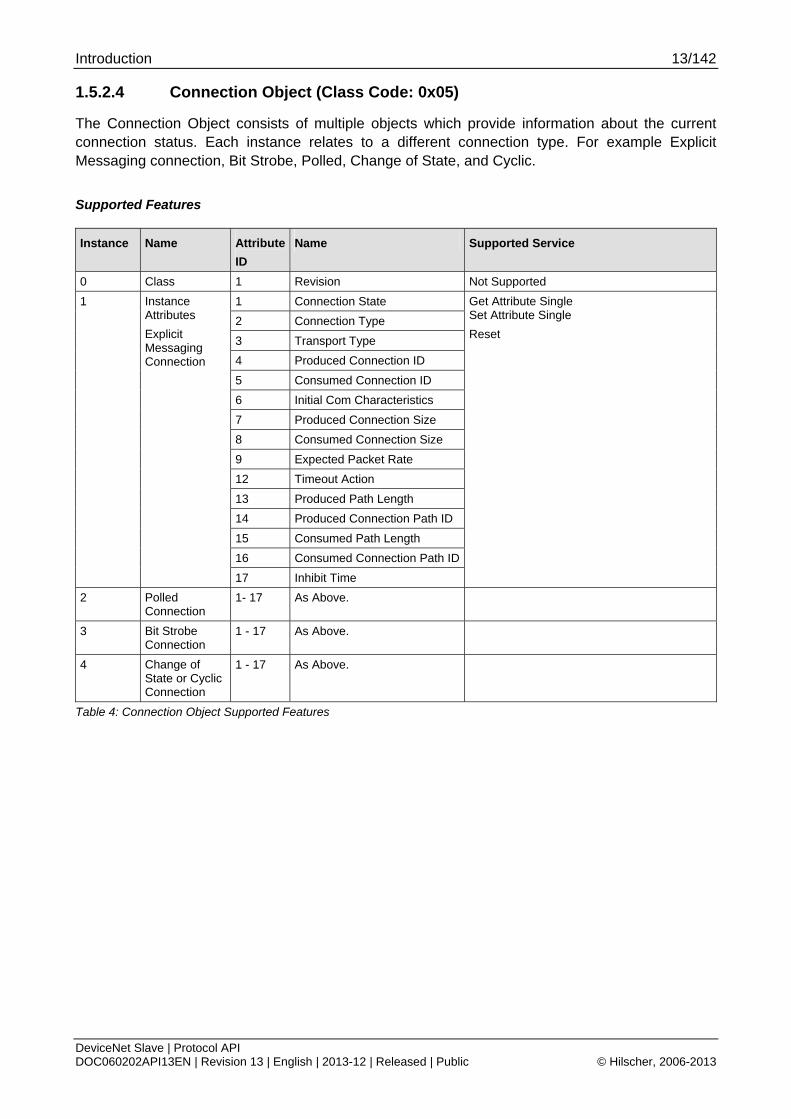
1.5.2.4 Connection Object (Class Code: 0x05)
The Connection Object consists of multiple objects which provide information about the current connection status. Each instance relates to a different connection type. For example Explicit Messaging connection, Bit Strobe, Polled, Change of State, and Cyclic.
Supported Features
Instance Name Attribute
ID
Name Supported Service
0 Class 1 Revision Not Supported
1 Connection State
2 Connection Type
3 Transport Type
4 Produced Connection ID
5 Consumed Connection ID
6 Initial Com Characteristics
7 Produced Connection Size
8 Consumed Connection Size
9 Expected Packet Rate
12 Timeout Action
13 Produced Path Length
14 Produced Connection Path ID
15 Consumed Path Length
16 Consumed Connection Path ID
1 Instance Attributes
Explicit Messaging Connection
17 Inhibit Time
Get Attribute Single Set Attribute Single
Reset
2 Polled Connection
1- 17 As Above.
3 Bit Strobe Connection
1 - 17 As Above.
4 Change of State or Cyclic Connection
1 - 17 As Above.
Table 4: Connection Object Supported Features
Introduction 14/142
DeviceNet Slave | Protocol API DOC060202API13EN | Revision 13 | English | 2013-12 | Released | Public © Hilscher, 2006-2013
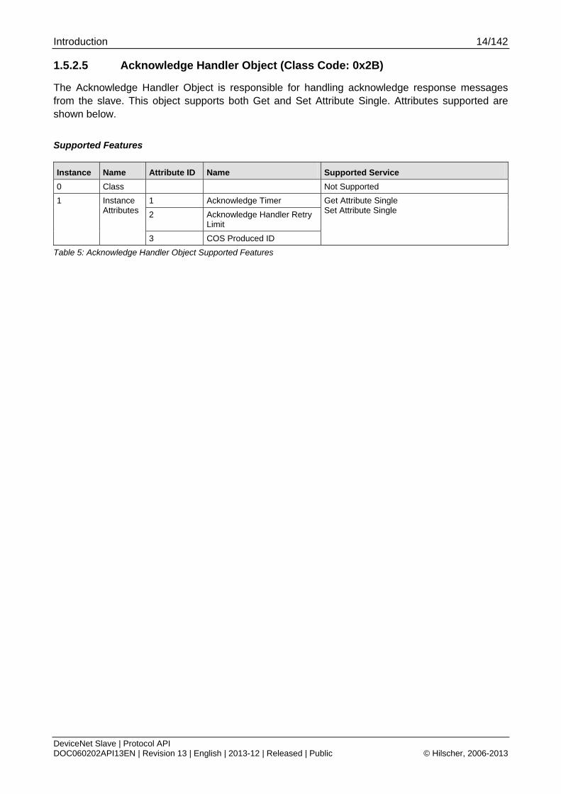
1.5.2.5 Acknowledge Handler Object (Class Code: 0x2B)
The Acknowledge Handler Object is responsible for handling acknowledge response messages from the slave. This object supports both Get and Set Attribute Single. Attributes supported are shown below.
Supported Features
Instance Name Attribute ID Name Supported Service
0 Class Not Supported
1 Acknowledge Timer
2 Acknowledge Handler Retry Limit
1 Instance Attributes
3 COS Produced ID
Get Attribute Single Set Attribute Single
Table 5: Acknowledge Handler Object Supported Features

Introduction 15/142
DeviceNet Slave | Protocol API DOC060202API13EN | Revision 13 | English | 2013-12 | Released | Public © Hilscher, 2006-2013
1.6 Terms, Abbreviations, Definitions
Term Description
AP Application on top of the Stack
AREP Application Reference End Point
ASCII American Standard Code for Information Interchange
BOI Bus-off interrupt
CAN Controller Area Network
CIP Common Industrial Protocol
COS Change of State
DL Data Link (Layer)
DNS DeviceNet Slave
DPM Dual Port Memory
LSB Least Significant Byte
MAC ID Media Access Control Identifier (i.e. address of a DeviceNet device)
MSB Most Significant Byte
ODVA Open DeviceNet Vendors Association
UCMM Unconnected Message Manager
Table 6: Terms, Abbreviations and Definitions
All variables, parameters and data used in this manual have basically the LSB/MSB (“Intel”) data representation. This corresponds to the convention of the Microsoft C Compiler.
1.7 References
This document is based on the following specifications:
1 Hilscher Gesellschaft für Systemautomation mbH: Dual-Port Memory Interface Manual - netX based products. Revision 12, English, 2011
2 ODVA: The CIP Networks Library, Volume 1, “Common Industrial Protocol (CIP™)”, Edition 3.10, April 2011
3 ODVA: The CIP Networks Library, Volume 3, “DeviceNet Adaptation of CIP”, Edition 1.11, April 2011
Table 7: References
Introduction 16/142
DeviceNet Slave | Protocol API DOC060202API13EN | Revision 13 | English | 2013-12 | Released | Public © Hilscher, 2006-2013
1.8 Legal Notes
1.8.1 Copyright © 2006-2013 Hilscher Gesellschaft für Systemautomation mbH
All rights reserved.
The images, photographs and texts in the accompanying material (user manual, accompanying texts, documentation, etc.) are protected by German and international copyright law as well as international trade and protection provisions. You are not authorized to duplicate these in whole or in part using technical or mechanical methods (printing, photocopying or other methods), to manipulate or transfer using electronic systems without prior written consent. You are not permitted to make changes to copyright notices, markings, trademarks or ownership declarations. The included diagrams do not take the patent situation into account. The company names and product descriptions included in this document may be trademarks or brands of the respective owners and may be trademarked or patented. Any form of further use requires the explicit consent of the respective rights owner.
1.8.2 Important Notes
The user manual, accompanying texts and the documentation were created for the use of the products by qualified experts, however, errors cannot be ruled out. For this reason, no guarantee can be made and neither juristic responsibility for erroneous information nor any liability can be assumed. Descriptions, accompanying texts and documentation included in the user manual do not present a guarantee nor any information about proper use as stipulated in the contract or a warranted feature. It cannot be ruled out that the user manual, the accompanying texts and the documentation do not correspond exactly to the described features, standards or other data of the delivered product. No warranty or guarantee regarding the correctness or accuracy of the information is assumed.
We reserve the right to change our products and their specification as well as related user manuals, accompanying texts and documentation at all times and without advance notice, without obligation to report the change. Changes will be included in future manuals and do not constitute any obligations. There is no entitlement to revisions of delivered documents. The manual delivered with the product applies.
Hilscher Gesellschaft für Systemautomation mbH is not liable under any circumstances for direct, indirect, incidental or follow-on damage or loss of earnings resulting from the use of the information contained in this publication.
Introduction 17/142
DeviceNet Slave | Protocol API DOC060202API13EN | Revision 13 | English | 2013-12 | Released | Public © Hilscher, 2006-2013
1.8.3 Exclusion of Liability
The software was produced and tested with utmost care by Hilscher Gesellschaft für Systemautomation mbH and is made available as is. No warranty can be assumed for the performance and flawlessness of the software for all usage conditions and cases and for the results produced when utilized by the user. Liability for any damages that may result from the use of the hardware or software or related documents, is limited to cases of intent or grossly negligent violation of significant contractual obligations. Indemnity claims for the violation of significant contractual obligations are limited to damages that are foreseeable and typical for this type of contract.
It is strictly prohibited to use the software in the following areas:
for military purposes or in weapon systems;
for the design, construction, maintenance or operation of nuclear facilities;
in air traffic control systems, air traffic or air traffic communication systems;
in life support systems;
in systems in which failures in the software could lead to personal injury or injuries leading to death.
We inform you that the software was not developed for use in dangerous environments requiring fail-proof control mechanisms. Use of the software in such an environment occurs at your own risk. No liability is assumed for damages or losses due to unauthorized use.
1.8.4 Export
The delivered product (including the technical data) is subject to export or import laws as well as the associated regulations of different counters, in particular those of Germany and the USA. The software may not be exported to countries where this is prohibited by the United States Export Administration Act and its additional provisions. You are obligated to comply with the regulations at your personal responsibility. We wish to inform you that you may require permission from state authorities to export, re-export or import the product.
Fundamentals 18/142
DeviceNet Slave | Protocol API DOC060202API13EN | Revision 13 | English | 2013-12 | Released | Public © Hilscher, 2006-2013
2 Fundamentals
2.1 General Access Mechanisms on netX Systems
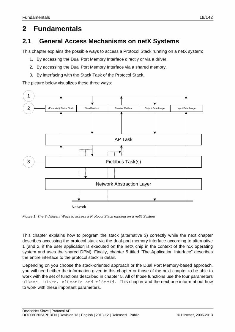
This chapter explains the possible ways to access a Protocol Stack running on a netX system:
1. By accessing the Dual Port Memory Interface directly or via a driver.
2. By accessing the Dual Port Memory Interface via a shared memory.
3. By interfacing with the Stack Task of the Protocol Stack.
The picture below visualizes these three ways:
(Extended) Status Block Send Mailbox Reveive Mailbox Output Data Image Input Data Image
Network Abstraction Layer
Fieldbus Task(s)
Network
AP Task
1
3
2
Figure 1: The 3 different Ways to access a Protocol Stack running on a netX System
This chapter explains how to program the stack (alternative 3) correctly while the next chapter describes accessing the protocol stack via the dual-port memory interface according to alternative 1 (and 2, if the user application is executed on the netX chip in the context of the rcX operating system and uses the shared DPM). Finally, chapter 5 titled “The Application Interface” describes the entire interface to the protocol stack in detail.
Depending on you choose the stack-oriented approach or the Dual Port Memory-based approach, you will need either the information given in this chapter or those of the next chapter to be able to work with the set of functions described in chapter 5. All of those functions use the four parameters ulDest, ulSrc, ulDestId and ulSrcId. This chapter and the next one inform about how to work with these important parameters.
Fundamentals 19/142
DeviceNet Slave | Protocol API DOC060202API13EN | Revision 13 | English | 2013-12 | Released | Public © Hilscher, 2006-2013
2.2 Accessing the Protocol Stack by Programming the AP Task’s Queue
In general, programming the AP task or the stack has to be performed according to the rules explained in the Hilscher Task Layer Reference Manual. There you can also find more information about the variables discussed in the following.
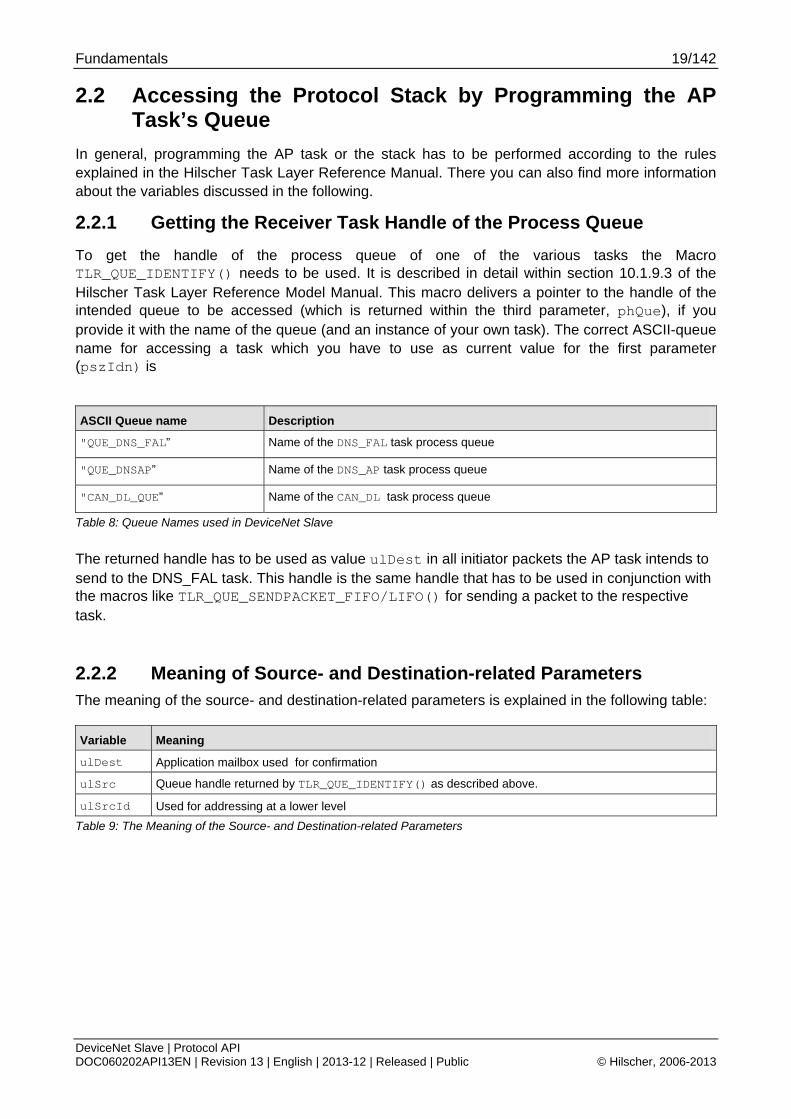
2.2.1 Getting the Receiver Task Handle of the Process Queue
To get the handle of the process queue of one of the various tasks the Macro TLR_QUE_IDENTIFY() needs to be used. It is described in detail within section 10.1.9.3 of the Hilscher Task Layer Reference Model Manual. This macro delivers a pointer to the handle of the intended queue to be accessed (which is returned within the third parameter, phQue), if you provide it with the name of the queue (and an instance of your own task). The correct ASCII-queue name for accessing a task which you have to use as current value for the first parameter (pszIdn) is
ASCII Queue name Description
"QUE_DNS_FAL” Name of the DNS_FAL task process queue
"QUE_DNSAP” Name of the DNS_AP task process queue
"CAN_DL_QUE” Name of the CAN_DL task process queue
Table 8: Queue Names used in DeviceNet Slave
The returned handle has to be used as value ulDest in all initiator packets the AP task intends to send to the DNS_FAL task. This handle is the same handle that has to be used in conjunction with the macros like TLR_QUE_SENDPACKET_FIFO/LIFO() for sending a packet to the respective task.
2.2.2 Meaning of Source- and Destination-related Parameters The meaning of the source- and destination-related parameters is explained in the following table:
Variable Meaning
ulDest Application mailbox used for confirmation
ulSrc Queue handle returned by TLR_QUE_IDENTIFY() as described above.
ulSrcId Used for addressing at a lower level
Table 9: The Meaning of the Source- and Destination-related Parameters

Fundamentals 20/142
DeviceNet Slave | Protocol API DOC060202API13EN | Revision 13 | English | 2013-12 | Released | Public © Hilscher, 2006-2013
For more information about programming the AP task’s stack queue, please refer to the Hilscher Task Layer Reference Model Manual. Especially the following sections might be of interest in this context:
1. Section 7 “Queue-Packets”
2. Section 10.1.9 “Queuing Mechanism”
2.3 Accessing the Protocol Stack via the Dual Port Memory Interface
This chapter defines the application interface of the DeviceNet-Slave Stack.
2.3.1 Communication via Mailboxes
The mailbox of each communication channel has two areas that are used for non-cyclic message transfer to and from the netX.
Send Mailbox Packet transfer from host system to netX firmware
Receive Mailbox Packet transfer from netX firmware to host system
For more details about acyclic data transfer via mailboxes see section 3.2. The concept of using messages called packets in this context, is described in detail in section 3.2.1 “General Structure of Messages or Packets for Non-Cyclic Data Exchange” while the possible codes that may appear are listed in section 3.2.2. “Status & Error Codes”.
However, this section concentrates on correct addressing the mailboxes.
Fundamentals 21/142
DeviceNet Slave | Protocol API DOC060202API13EN | Revision 13 | English | 2013-12 | Released | Public © Hilscher, 2006-2013
2.3.2 Using Source and Destination Variables correctly
2.3.2.1 How to use ulDest for Addressing rcX and the netX Protocol Stack by the System and Channel Mailbox
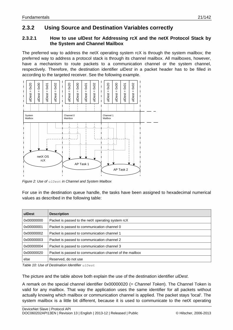
The preferred way to address the netX operating system rcX is through the system mailbox; the preferred way to address a protocol stack is through its channel mailbox. All mailboxes, however, have a mechanism to route packets to a communication channel or the system channel, respectively. Therefore, the destination identifier ulDest in a packet header has to be filled in according to the targeted receiver. See the following example.
netX OSrcX
AP Task 1
AP Task 2
ulD
est
= 0
x00
ulD
est
= 0
x01
ulD
est
= 0
x02
ulD
est
= 0
x20
ulD
est
= 0
x00
ulD
est
= 0
x01
ulD
est
= 0
x02
ulD
est
= 0
x20
ulD
est
= 0
x00
ulD
est
= 0
x01
ulD
est
= 0
x02
ulD
est
= 0
x20
SystemMailbox
Channel 1Mailbox
Channel 0Mainbox
Figure 2: Use of ulDest in Channel and System Mailbox
For use in the destination queue handle, the tasks have been assigned to hexadecimal numerical values as described in the following table:
ulDest Description
0x00000000 Packet is passed to the netX operating system rcX
0x00000001 Packet is passed to communication channel 0
0x00000002 Packet is passed to communication channel 1
0x00000003 Packet is passed to communication channel 2
0x00000004 Packet is passed to communication channel 3
0x00000020 Packet is passed to communication channel of the mailbox
else Reserved, do not use
Table 10: Use of Destination Identifier ulDest
The picture and the table above both explain the use of the destination identifier ulDest.
A remark on the special channel identifier 0x00000020 (= Channel Token). The Channel Token is valid for any mailbox. That way the application uses the same identifier for all packets without actually knowing which mailbox or communication channel is applied. The packet stays 'local'. The system mailbox is a little bit different, because it is used to communicate to the netX operating
Fundamentals 22/142
DeviceNet Slave | Protocol API DOC060202API13EN | Revision 13 | English | 2013-12 | Released | Public © Hilscher, 2006-2013
system rcX. The rcX has its own range of valid commands codes and differs from a communication channel.
Unless there is a reply packet, the netX operating system returns it to the same mailbox the request packet went through. Consequently, the host application has to return its reply packet to the mailbox the request was received from.
2.3.2.2 How to use ulSrc and ulSrcId
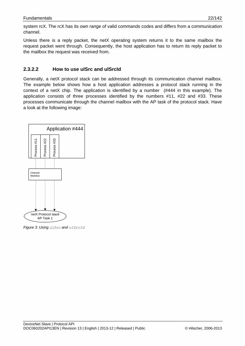
Generally, a netX protocol stack can be addressed through its communication channel mailbox. The example below shows how a host application addresses a protocol stack running in the context of a netX chip. The application is identified by a number (#444 in this example). The application consists of three processes identified by the numbers #11, #22 and #33. These processes communicate through the channel mailbox with the AP task of the protocol stack. Have a look at the following image:
Application #444
netX Protocol stackAP Task 1
Pro
cess
#22
Pro
cess
#33
Pro
cess
#11
ChannelMainbox
Figure 3: Using ulSrc and ulSrcId
Fundamentals 23/142
DeviceNet Slave | Protocol API DOC060202API13EN | Revision 13 | English | 2013-12 | Released | Public © Hilscher, 2006-2013
Example:
This example applies to command messages initiated by a process in the context of the host application. If the process #22 sends a packet through the channel mailbox to the AP task, the packet header has to be filled in as follows:
Object Variable
Name
Numeric
Value
Explanation
Destination Queue Handle
ulDest = 32
(0x00000020)
This value needs always to be set to 0x00000020 (the channel token) when accessing the protocol stack via the local communication channel mailbox.
Source Queue Handle
ulSrc = 444 Denotes the host application (#444).
Destination Identifier
ulDestId = 0 In this example it is not necessary to use the destination identifier.
Source Identifier ulSrcId = 22 Denotes the process number of the process within the host application and needs therefore to be supplied by the programmer of the host application.
For packets through the channel mailbox, the application uses 32 (= 0x20, Channel Token) for the destination queue handler ulDest. The source queue handler ulSrc and the source identifier ulSrcId are used to identify the originator of a packet. The destination identifier ulDestId can be used to address certain resources in the protocol stack. It is not used in this example. The source queue handler ulSrc has to be filled in. Therefore its use is mandatory; the use of ulSrcId is optional.
The netX operating system passes the request packet to the protocol stack's AP task. The protocol stack then builds a reply to the packet and returns it to the mailbox. The application has to make sure that the packet finds its way back to the originator (process #22 in the example).
2.3.2.3 How to Route rcX Packets
To route an rcX packet the source identifier ulSrcId and the source queues handler ulSrc in the packet header hold the identification of the originating process. The router saves the original handle from ulSrcId and ulSrc. The router uses a handle of its own choices for ulSrcId and ulSrc before it sends the packet to the receiving process. That way the router can identify the corresponding reply packet and matches the handle from that packet with the one stored earlier. Now the router replaces its handles with the original handles and returns the packet to the originating process.
Fundamentals 24/142
DeviceNet Slave | Protocol API DOC060202API13EN | Revision 13 | English | 2013-12 | Released | Public © Hilscher, 2006-2013
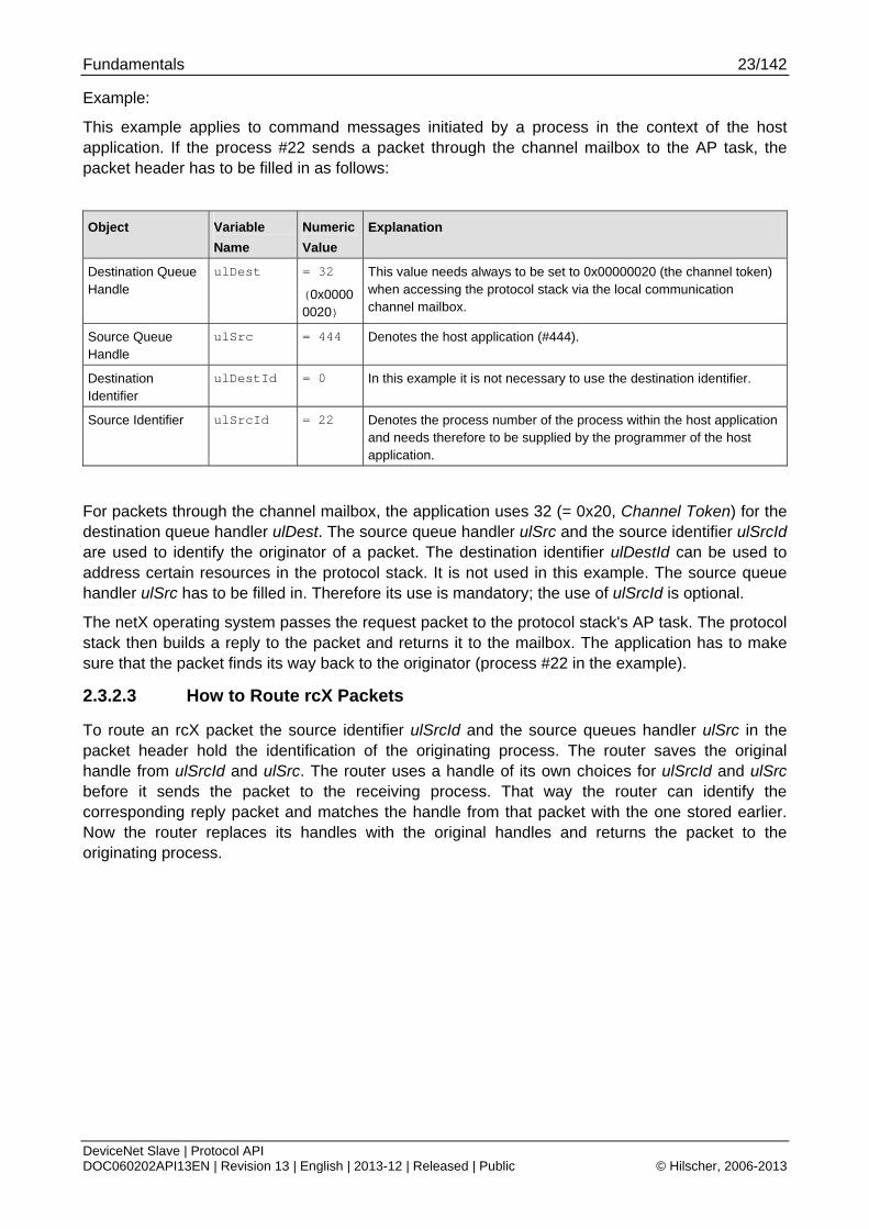
2.3.3 Obtaining useful Information about the Communication Channel
A communication channel represents a part of the Dual Port Memory and usually consists of the following elements:
Output Data Image
is used to transfer cyclic process data to the network (normal or high-priority) Input Data Image
is used to transfer cyclic process data from the network (normal or high-priority) Send Mailbox
is used to transfer non-cyclic data to the netX Receive Mailbox
is used to transfer non-cyclic data from the netX Control Block
allows the host system to control certain channel functions Common Status Block
holds information common to all protocol stacks Extended Status Block
holds protocol specific network status information
This section describes a procedure how to obtain useful information for accessing the communication channel(s) of your netX device and to check if it is ready for correct operation.
Proceed as follows:
1) Start with reading the channel information block within the system channel (usually starting at address 0x0030).
2) Then you should check the hardware assembly options of your netX device. They are located within the system information block following offset 0x0010 and stored as data type UINT16. The following table explains the relationship between the offsets and the corresponding xC Ports of the netX device:
0x0010 Hardware Assembly Options for xC Port[0]
0x0012 Hardware Assembly Options for xC Port[1]
0x0014 Hardware Assembly Options for xC Port[2]
0x0016 Hardware Assembly Options for xC Port[3]
Check each of the hardware assembly options whether its value has been set to RCX_HW_ASSEMBLY_DEVICENET = 0x0040
If true, this denotes that this xCPort is suitable for running the DeviceNet Slave protocol stack. Otherwise, this port is designed for another communication protocol. In most cases, xC Port[2] will be used for field-bus systems, while xC Port[0] and xC Port[1] are normally used for Ethernet communication.

Fundamentals 25/142
DeviceNet Slave | Protocol API DOC060202API13EN | Revision 13 | English | 2013-12 | Released | Public © Hilscher, 2006-2013
3) You can find information about the corresponding communication channel (0…3) under the following addresses:
0x0050 Communication Channel 0
0x0060 Communication Channel 1
0x0070 Communication Channel 2
0x0080 Communication Channel 3
In devices which support only one communication system which is usually the case (either a single field-bus system or a single standard for Industrial-Ethernet communication), always communication channel 0 will be used. In devices supporting more than one communication system you should also check the other communication channels.
4) There you can find such information as the ID (containing channel number and port number) of the communication channel, the size and the location of the handshake cells, the overall number of blocks within the communication channel and the size of the channel in bytes. Evaluate this information precisely in order to access the communication channel correctly.
The information is delivered as follows:
Size of Channel in Bytes
Address Data Type
Description
0x0050 UINT8 Channel Type = COMMUNICATION
(must have the fixed value
define RCX_CHANNEL_TYPE_COMMUNICATION = 0x05)
0x0051 UINT8 ID (Channel Number, Port Number)
0x0052 UINT8 Size / Position Of Handshake Cells
0x0053 UINT8 Total Number Of Blocks Of This Channel
0x0054 UINT32 Size Of Channel In Bytes
0x0058 UINT8[8] Reserved (set to zero)
These addresses correspond to communication channel 0, for communication channels 1, 2 and 3 you have to add an offset of 0x0010, 0x0020 or 0x0030 to the address values, respectively.
5) Finally, you can access the communication channel using the addresses you determined previously. For more information how to do this, please refer to the netX DPM Manual, especially section 3.2 “Communication Channel".

Fundamentals 26/142
DeviceNet Slave | Protocol API DOC060202API13EN | Revision 13 | English | 2013-12 | Released | Public © Hilscher, 2006-2013
2.4 Client/Server Mechanism
2.4.1 Application as Client
The host application may send request packets to the netX firmware at any time (transition 1 2). Depending on the protocol stack running on the netX, parallel packets are not permitted (see protocol specific manual for details). The netX firmware sends a confirmation packet in return, signaling success or failure (transition 3 4) while processing the request.
The host application has to register with the netX firmware in order to receive indication packets (transition 5 6). Depending on the protocol stack, this is done either implicitly or explicitly (if application wants to receive unsolicited GET/SET attribute packets). Details on when and how to register for certain events is described in the protocol specific manual. Depending on the command code of the indication packet, a response packet to the netX firmware may or may not be required (transition 7 8).
Figure 1 - Transition Chart Application as Client
The host application sends request packets to the netX firmware.
The netX firmware sends a confirmation packet in return.
The host application receives indication packets from the netX firmware.
The host application sends response packet to the netX firmware (may not be required).
Request Confirmation
Indication Response
Application netX
Fundamentals 27/142
DeviceNet Slave | Protocol API DOC060202API13EN | Revision 13 | English | 2013-12 | Released | Public © Hilscher, 2006-2013
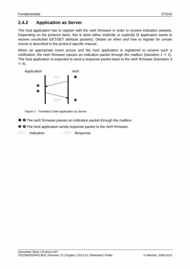
2.4.2 Application as Server
The host application has to register with the netX firmware in order to receive indication packets. Depending on the protocol stack, this is done either implicitly or explicitly (if application wants to receive unsolicited GET/SET attribute packets). Details on when and how to register for certain events is described in the protocol specific manual.
When an appropriate event occurs and the host application is registered to receive such a notification, the netX firmware passes an indication packet through the mailbox (transition 1 2). The host application is expected to send a response packet back to the netX firmware (transition 3 4).
Figure 2 - Transition Chart Application as Server
The netX firmware passes an indication packet through the mailbox.
The host application sends response packet to the netX firmware.
Indication Response
Application netX

Dual-Port Memory 28/142
DeviceNet Slave | Protocol API DOC060202API13EN | Revision 13 | English | 2013-12 | Released | Public © Hilscher, 2006-2013
3 Dual-Port Memory All data in the dual-port memory is structured in blocks. According to their functions, these blocks use different data transfer mechanisms. For example, data transfer through mailboxes uses a synchronized handshake mechanism between host system and netX firmware. The same is true for IO data images, when a buffered handshake mode is configured. Other blocks, like the status block, are read by the host application and use no synchronization mechanism.
Types of blocks in the dual-port memory are outlined below:
Mailbox transfer non-cyclic messages or packages with a header for routing information
Data Area holds the process image for cyclic IO data or user defined data structures
Control Block is used to signal application related state to the netX firmware
Status Block holds information regarding the current network state
Change of State Is a part of the control and status block containing a collection of flags, that initiate
execution of certain commands or signal a change of state
3.1 Cyclic Data (Input/Output Data)
The input block holds the process data image received from the network whereas the output block holds data sent to the network.
For the controlled / buffered mode, the protocol stack updates the process data in the internal input buffer for each valid bus cycle. Each IO block uses handshake bits for access synchronization. Input and output data block handshake operates independently from each other. When the application toggles the input handshake bit, the protocol stack copies the data from the internal buffer into the input data image of the dual-port memory. Now the application can copy data from the dual-port memory and then give control back to the protocol stack by toggling the appropriate input handshake bit. When the application/driver toggles the output handshake bit, the protocol stack copies the data from the output data image of the dual-port memory into the internal buffer. From there the data is transferred to the network. The protocol stack toggles the handshake bits back, indicating to the application that the transfer is finished and a new data exchange cycle may start. This mode guarantees data consistency over both input and output area.
Dual-Port Memory 29/142
DeviceNet Slave | Protocol API DOC060202API13EN | Revision 13 | English | 2013-12 | Released | Public © Hilscher, 2006-2013
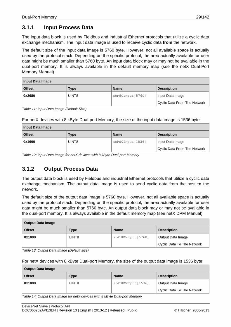
3.1.1 Input Process Data
The input data block is used by Fieldbus and industrial Ethernet protocols that utilize a cyclic data exchange mechanism. The input data image is used to receive cyclic data from the network.
The default size of the input data image is 5760 byte. However, not all available space is actually used by the protocol stack. Depending on the specific protocol, the area actually available for user data might be much smaller than 5760 byte. An input data block may or may not be available in the dual-port memory. It is always available in the default memory map (see the netX Dual-Port Memory Manual).
Input Data Image
Offset Type Name Description
0x2680
UINT8 abPd0Input[5760] Input Data Image
Cyclic Data From The Network
Table 11: Input Data Image (Default Size)
For netX devices with 8 kByte Dual-port Memory, the size of the input data image is 1536 byte:
Input Data Image
Offset Type Name Description
0x1600 UINT8 abPd0Input[1536] Input Data Image
Cyclic Data From The Network
Table 12: Input Data Image for netX devices with 8 kByte Dual-port Memory
3.1.2 Output Process Data
The output data block is used by Fieldbus and industrial Ethernet protocols that utilize a cyclic data exchange mechanism. The output data Image is used to send cyclic data from the host to the network.
The default size of the output data image is 5760 byte. However, not all available space is actually used by the protocol stack. Depending on the specific protocol, the area actually available for user data might be much smaller than 5760 byte. An output data block may or may not be available in the dual-port memory. It is always available in the default memory map (see netX DPM Manual).
Output Data Image
Offset Type Name Description
0x1000 UINT8 abPd0Output[5760] Output Data Image
Cyclic Data To The Network
Table 13: Output Data Image (Default size)
For netX devices with 8 kByte Dual-port Memory, the size of the output data image is 1536 byte:
Output Data Image
Offset Type Name Description
0x1000 UINT8 abPd0Output[1536] Output Data Image
Cyclic Data To The Network
Table 14: Output Data Image for netX devices with 8 kByte Dual-port Memory
Dual-Port Memory 30/142
DeviceNet Slave | Protocol API DOC060202API13EN | Revision 13 | English | 2013-12 | Released | Public © Hilscher, 2006-2013
3.2 Acyclic Data (Mailboxes)
The mailbox of each communication channel has two areas that are used for non-cyclic message transfer.
Send Mailbox
Packet transfer from host system to firmware
Receive Mailbox
Packet transfer from firmware to host system
The send and receive mailbox areas are used by Fieldbus protocols providing a non-cyclic data exchange mechanism. Another use of the mailbox system is to allow access to the firmware running on the netX chip itself for diagnostic and identification purposes.
The send mailbox is used to transfer acyclic data to the network or to the firmware. The receive mailbox is used to transfer acyclic data from the network or from the firmware.
A send/receive mailbox may or may not be available in the communication channel. It depends on the function of the firmware whether or not a mailbox is needed. The location of the system mailbox and the channel mailbox is described in the netX DPM Interface Manual.
Note: Each mailbox can hold one packet at a time. The netX firmware stores packets that are not retrieved by the host application in a packet queue. This queue has limited space and may fill up so new packets maybe lost. To avoid these data loss situations, it is strongly recommended to empty the mailbox frequently, even if packets are not expected by the host application. Unexpected command packets should be returned to the sender with an Unknown Command in the status field; unexpected reply messages can be discarded.

Dual-Port Memory 31/142
DeviceNet Slave | Protocol API DOC060202API13EN | Revision 13 | English | 2013-12 | Released | Public © Hilscher, 2006-2013
3.2.1 General Structure of Messages or Packets for Non-Cyclic Data Exchange
The non-cyclic packets through the netX mailbox have the following structure:
Structure Information
Variable Type Value / Range Description
tHead - Structure Information
ulDest UINT32 Destination Queue Handle
ulSrc UINT32 Source Queue Handle
ulDestId UINT32 Destination Queue Reference
ulSrcId UINT32 Source Queue Reference
ulLen UINT32 Packet Data Length (In Bytes)
ulId UINT32 Packet Identification As Unique Number
ulSta UINT32 Status / Error Code
ulCmd UINT32 Command / Response
ulExt UINT32 Extension Flags
ulRout UINT32 Routing Information
tData - Structure Information
… … User Data
Specific To The Command
Table 15: General Structure of Packets for non-cyclic Data Exchange.
Some of the fields are mandatory; some are conditional; others are optional. However, the size of a packet is always at least 10 double-words or 40 bytes. Depending on the command, a packet may or may not have a data field. If present, the content of the data field is specific to the command, respectively the reply.
Destination Queue Handle
The ulDest field identifies a task queue in the context of the netX firmware. The task queue represents the final receiver of the packet and is assigned to a protocol stack. The ulDest field has to be filled out in any case. Otherwise, the netX operating system cannot route the packet. This field is mandatory.
Dual-Port Memory 32/142
DeviceNet Slave | Protocol API DOC060202API13EN | Revision 13 | English | 2013-12 | Released | Public © Hilscher, 2006-2013
Source Queue Handle
The ulSrc field identifies the sender of the packet. In the context of the netX firmware (inter-task communication) this field holds the identifier of the sending task. Usually, a driver uses this field for its own handle, but it can hold any handle of the sending process. Using this field is mandatory. The receiving task does not evaluate this field and passes it back unchanged to the originator of the packet.
Destination Identifier
The ulDestId field identifies the destination of an unsolicited packet from the netX firmware to the host system. It can hold any handle that helps to identify the receiver. Therefore, its use is mandatory for unsolicited packets. The receiver of unsolicited packets has to register for this.
Source Identifier
The ulSrcId field identifies the originator of a packet. This field is used by a host application, which passes a packet from an external process to an internal netX task. The ulSrcId field holds the handle of the external process. When netX operating system returns the packet, the application can identify the packet and returns it to the originating process. The receiving task on the netX does not evaluated this field and passes it back unchanged. For inter-task communication, this field is not used.
Length of Data Field
The ulLen field holds the size of the data field in bytes. It defines the total size of the packet’s payload that follows the packet’s header. The size of the header is not included in ulLen. So the total size of a packet is the size from ulLen plus the size of packet’s header. Depending on the command, a data field may or may not be present in a packet. If no data field is included, the length field is set to zero.
Identifier
The ulId field is used to identify a specific packet among others of the same kind. That way the application or driver can match a specific reply or confirmation packet to a previous request packet. The receiving task does not change this field and passes it back to the originator of the packet. Its use is optional in most of the cases. But it is mandatory for sequenced packets. Example: Downloading big amounts of data that does not fit into a single packet. For a sequence of packets the identifier field is incremented by one for every new packet.
Status / Error Code
The ulSta field is used in response or confirmation packets. It informs the originator of the packet about success or failure of the execution of the command. The field may be also used to hold status information in a request packet.

Dual-Port Memory 33/142
DeviceNet Slave | Protocol API DOC060202API13EN | Revision 13 | English | 2013-12 | Released | Public © Hilscher, 2006-2013
Command / Response
The ulCmd field holds the command code or the response code, respectively. The command/response is specific to the receiving task. If a task is not able to execute certain commands, it will return the packet with an error indication. A command is always even (the least significant bit is zero). In the response packet, the command code is incremented by one indicating a confirmation to the request packet.
Extension Flags
The extension field ulExt is used for controlling packets that are sent in a sequenced manner. The extension field indicates the first, last or a packet of a sequence. If sequencing is not required, the extension field is not used and set to zero.
Routing Information
The ulRout field is used internally by the netX firmware only. It has no meaning to a driver type application and therefore set to zero.
User Data Field
This field contains data related to the command specified in ulCmd field. Depending on the command, a packet may or may not have a data field. The length of the data field is given in the ulLen field.
Dual-Port Memory 34/142
DeviceNet Slave | Protocol API DOC060202API13EN | Revision 13 | English | 2013-12 | Released | Public © Hilscher, 2006-2013
3.2.2 Status & Error Codes
The following status and error codes can be returned in ulSta by the operating system rcX: List of codes see manual named netX Dual-Port Memory Interface.
3.2.3 Differences between System and Channel Mailboxes
The mailbox system on netX provides a non-cyclic data transfer channel for Fieldbus and industrial Ethernet protocols. Another use of the mailbox is allowing access to the firmware running on the netX chip itself for diagnostic purposes. There is always a send and a receive mailbox. Send and receive mailboxes utilize handshake bits to synchronize these data or diagnostic packages through the mailbox. There is a pair of handshake bits for both the send and receive mailbox.
The netX operating system rcX only uses the system mailbox.
The system mailbox, however, has a mechanism to route packets to a communication channel.
A channel mailbox passes packets to its own protocol stack only.
Dual-Port Memory 35/142
DeviceNet Slave | Protocol API DOC060202API13EN | Revision 13 | English | 2013-12 | Released | Public © Hilscher, 2006-2013
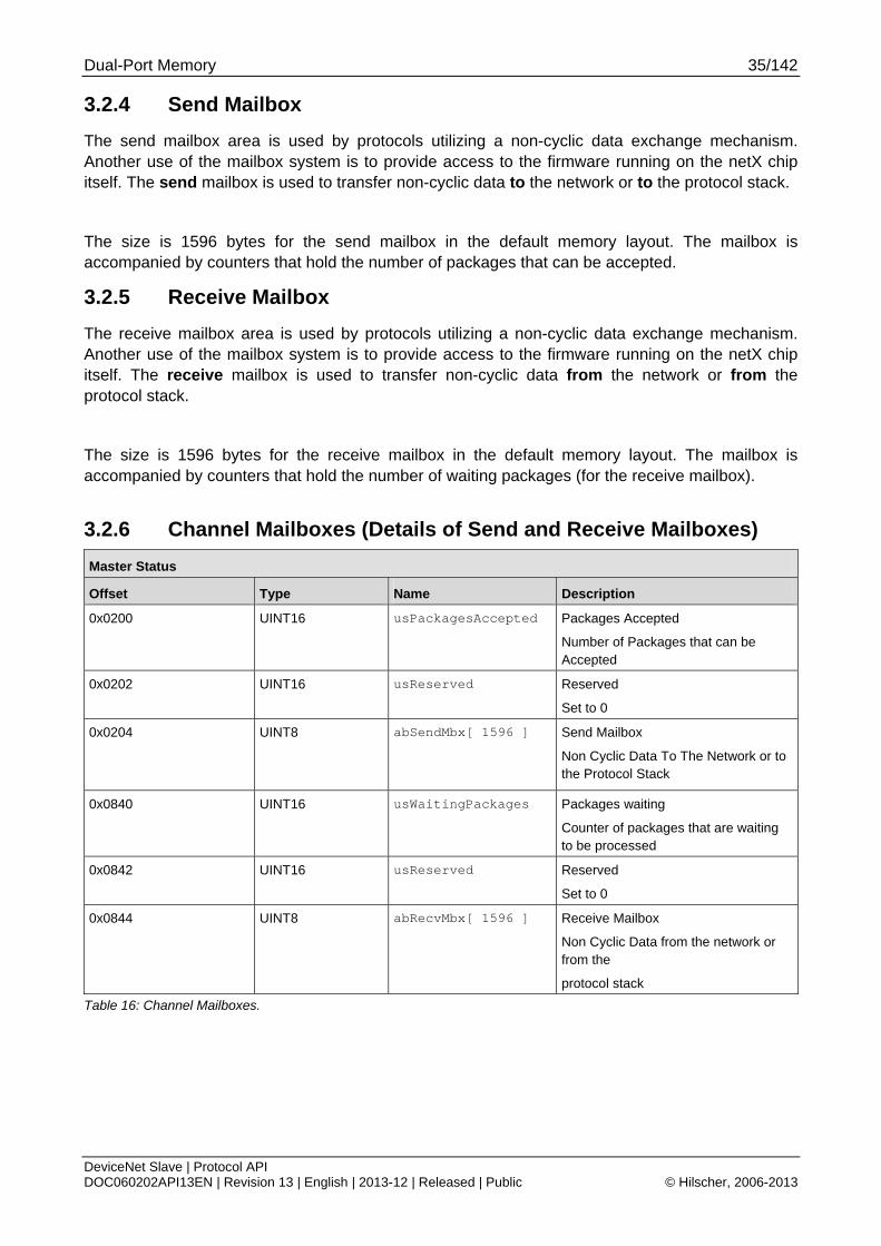
3.2.4 Send Mailbox
The send mailbox area is used by protocols utilizing a non-cyclic data exchange mechanism. Another use of the mailbox system is to provide access to the firmware running on the netX chip itself. The send mailbox is used to transfer non-cyclic data to the network or to the protocol stack.
The size is 1596 bytes for the send mailbox in the default memory layout. The mailbox is accompanied by counters that hold the number of packages that can be accepted.
3.2.5 Receive Mailbox
The receive mailbox area is used by protocols utilizing a non-cyclic data exchange mechanism. Another use of the mailbox system is to provide access to the firmware running on the netX chip itself. The receive mailbox is used to transfer non-cyclic data from the network or from the protocol stack.
The size is 1596 bytes for the receive mailbox in the default memory layout. The mailbox is accompanied by counters that hold the number of waiting packages (for the receive mailbox).
3.2.6 Channel Mailboxes (Details of Send and Receive Mailboxes)
Master Status
Offset Type Name Description
0x0200 UINT16 usPackagesAccepted Packages Accepted
Number of Packages that can be Accepted
0x0202 UINT16 usReserved Reserved
Set to 0
0x0204
UINT8 abSendMbx[ 1596 ] Send Mailbox
Non Cyclic Data To The Network or to the Protocol Stack
0x0840 UINT16 usWaitingPackages
Packages waiting
Counter of packages that are waiting to be processed
0x0842 UINT16 usReserved Reserved
Set to 0
0x0844 UINT8 abRecvMbx[ 1596 ]
Receive Mailbox
Non Cyclic Data from the network or from the
protocol stack
Table 16: Channel Mailboxes.

Dual-Port Memory 36/142
DeviceNet Slave | Protocol API DOC060202API13EN | Revision 13 | English | 2013-12 | Released | Public © Hilscher, 2006-2013
Channel Mailboxes Structure
typedef struct tagNETX_SEND_MAILBOX_BLOCK { UINT16 usPackagesAccepted; UINT16 usReserved; UINT8 abSendMbx[ 1596 ]; } NETX_SEND_MAILBOX_BLOCK; typedef struct tagNETX_RECV_MAILBOX_BLOCK { UINT16 usWaitingPackages; UINT16 usReserved; UINT8 abRecvMbx[ 1596 ]; } NETX_RECV_MAILBOX_BLOCK;
Dual-Port Memory 37/142
DeviceNet Slave | Protocol API DOC060202API13EN | Revision 13 | English | 2013-12 | Released | Public © Hilscher, 2006-2013
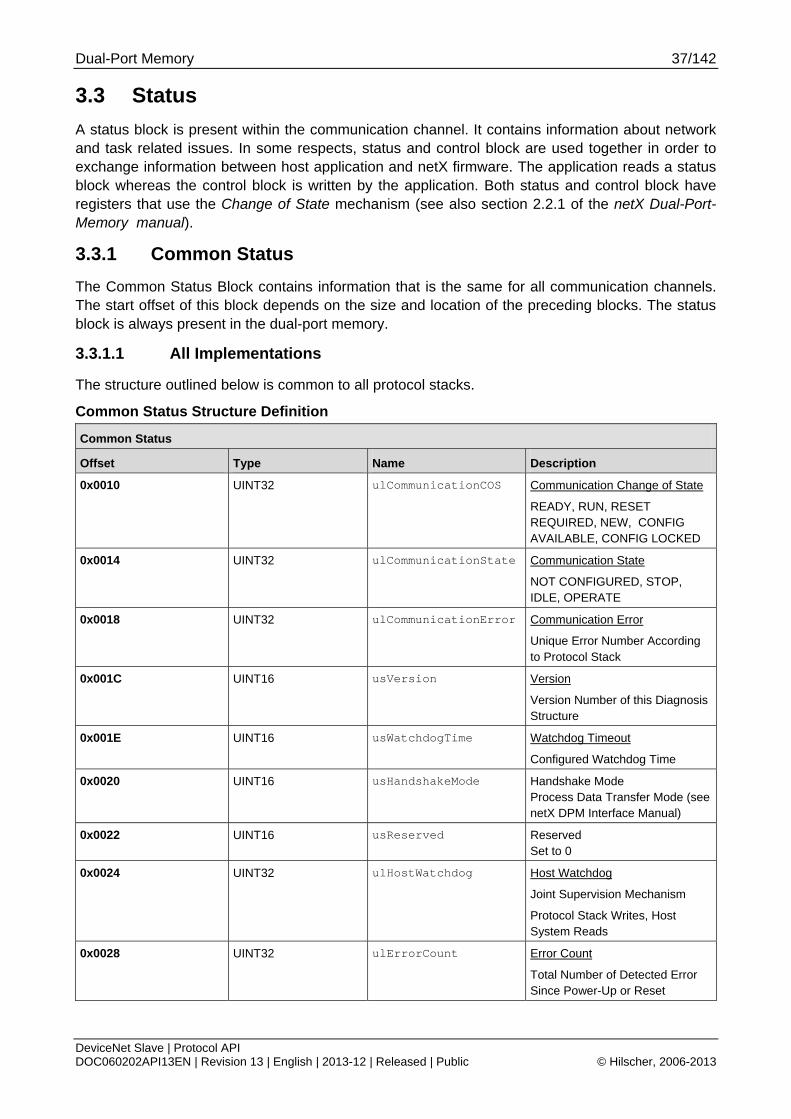
3.3 Status
A status block is present within the communication channel. It contains information about network and task related issues. In some respects, status and control block are used together in order to exchange information between host application and netX firmware. The application reads a status block whereas the control block is written by the application. Both status and control block have registers that use the Change of State mechanism (see also section 2.2.1 of the netX Dual-Port-Memory manual).
3.3.1 Common Status
The Common Status Block contains information that is the same for all communication channels. The start offset of this block depends on the size and location of the preceding blocks. The status block is always present in the dual-port memory.
3.3.1.1 All Implementations
The structure outlined below is common to all protocol stacks.
Common Status Structure Definition
Common Status
Offset Type Name Description
0x0010 UINT32 ulCommunicationCOS Communication Change of State
READY, RUN, RESET REQUIRED, NEW, CONFIG AVAILABLE, CONFIG LOCKED
0x0014 UINT32 ulCommunicationState Communication State
NOT CONFIGURED, STOP, IDLE, OPERATE
0x0018 UINT32 ulCommunicationError Communication Error
Unique Error Number According to Protocol Stack
0x001C UINT16 usVersion Version
Version Number of this Diagnosis Structure
0x001E UINT16 usWatchdogTime Watchdog Timeout
Configured Watchdog Time
0x0020 UINT16 usHandshakeMode Handshake Mode Process Data Transfer Mode (see netX DPM Interface Manual)
0x0022 UINT16 usReserved Reserved Set to 0
0x0024 UINT32 ulHostWatchdog Host Watchdog
Joint Supervision Mechanism
Protocol Stack Writes, Host System Reads
0x0028 UINT32 ulErrorCount Error Count
Total Number of Detected Error Since Power-Up or Reset
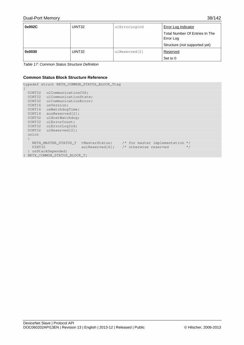
Dual-Port Memory 38/142
DeviceNet Slave | Protocol API DOC060202API13EN | Revision 13 | English | 2013-12 | Released | Public © Hilscher, 2006-2013
0x002C UINT32 ulErrorLoglnd Error Log Indicator
Total Number Of Entries In The Error Log
Structure (not supported yet)
0x0030 UINT32 ulReserved[2] Reserved
Set to 0
Table 17: Common Status Structure Definition
Common Status Block Structure Reference
typedef struct NETX_COMMON_STATUS_BLOCK_Ttag { UINT32 ulCommunicationCOS; UINT32 ulCommunicationState; UINT32 ulCommunicationError; UINT16 usVersion; UINT16 usWatchdogTime; UINT16 ausReserved[2]; UINT32 ulHostWatchdog; UINT32 ulErrorCount; UINT32 ulErrorLogInd; UINT32 ulReserved[2]; union { NETX_MASTER_STATUS_T tMasterStatus; /* for master implementation */ UINT32 aulReserved[6]; /* otherwise reserved */ } unStackDepended; } NETX_COMMON_STATUS_BLOCK_T;
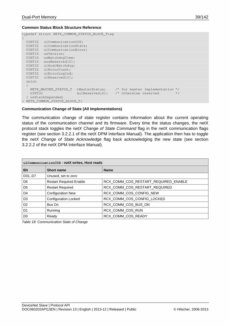
Dual-Port Memory 39/142
DeviceNet Slave | Protocol API DOC060202API13EN | Revision 13 | English | 2013-12 | Released | Public © Hilscher, 2006-2013
Common Status Block Structure Reference
typedef struct NETX_COMMON_STATUS_BLOCK_Ttag { UINT32 ulCommunicationCOS; UINT32 ulCommunicationState; UINT32 ulCommunicationError; UINT16 usVersion; UINT16 usWatchdogTime; UINT16 ausReserved[2]; UINT32 ulHostWatchdog; UINT32 ulErrorCount; UINT32 ulErrorLogInd; UINT32 ulReserved[2]; union { NETX_MASTER_STATUS_T tMasterStatus; /* for master implementation */ UINT32 aulReserved[6]; /* otherwise reserved */ } unStackDepended; } NETX_COMMON_STATUS_BLOCK_T;
Communication Change of State (All Implementations)
The communication change of state register contains information about the current operating status of the communication channel and its firmware. Every time the status changes, the netX protocol stack toggles the netX Change of State Command flag in the netX communication flags register (see section 3.2.2.1 of the netX DPM Interface Manual). The application then has to toggle the netX Change of State Acknowledge flag back acknowledging the new state (see section 3.2.2.2 of the netX DPM Interface Manual).
ulCommunicationCOS - netX writes, Host reads
Bit Short name Name
D31..D7 Unused, set to zero D6 Restart Required Enable RCX_COMM_COS_RESTART_REQUIRED_ENABLE
D5 Restart Required RCX_COMM_COS_RESTART_REQUIRED
D4 Configuration New RCX_COMM_COS_CONFIG_NEW
D3 Configuration Locked RCX_COMM_COS_CONFIG_LOCKED D2 Bus On RCX_COMM_COS_BUS_ON
D1 Running RCX_COMM_COS_RUN
D0 Ready RCX_COMM_COS_READY
Table 18: Communication State of Change
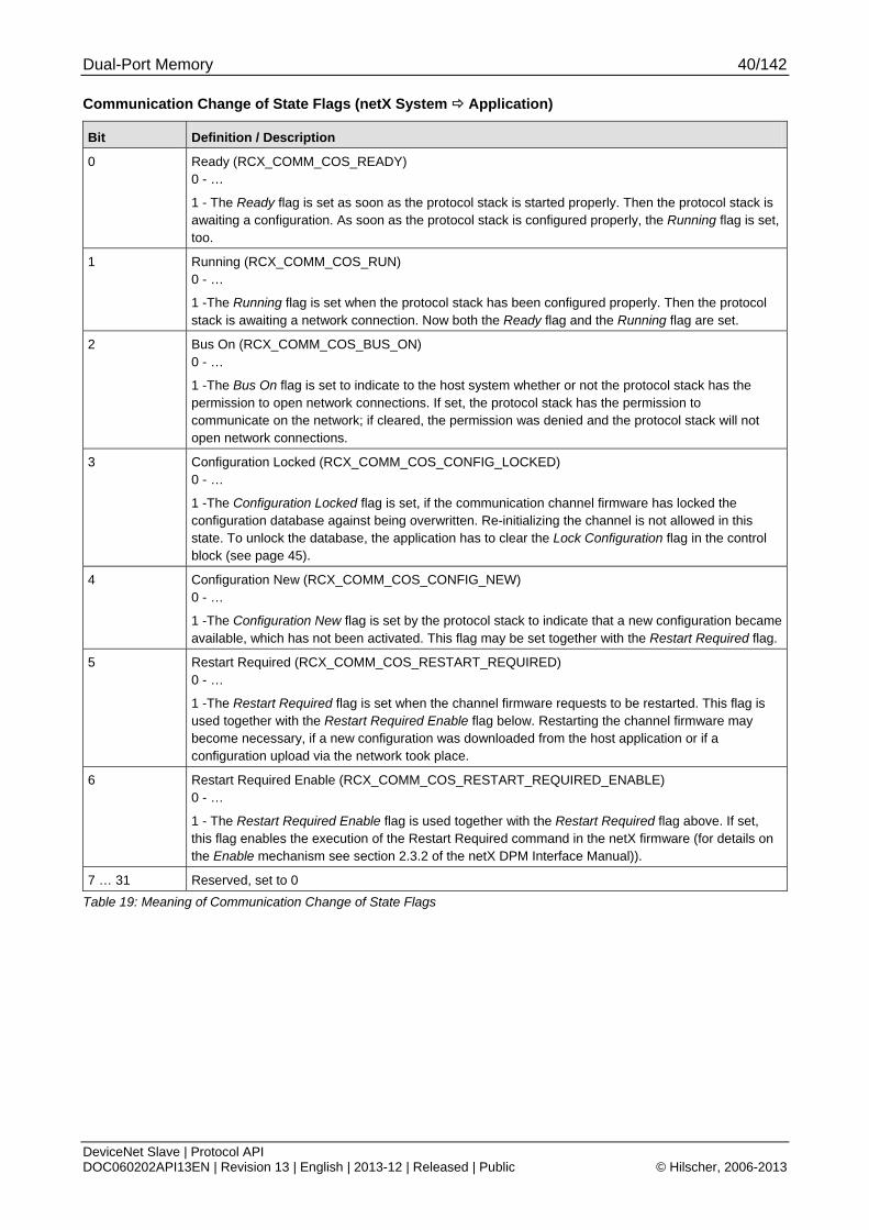
Dual-Port Memory 40/142
DeviceNet Slave | Protocol API DOC060202API13EN | Revision 13 | English | 2013-12 | Released | Public © Hilscher, 2006-2013
Communication Change of State Flags (netX System Application)
Bit Definition / Description
0 Ready (RCX_COMM_COS_READY) 0 - …
1 - The Ready flag is set as soon as the protocol stack is started properly. Then the protocol stack is awaiting a configuration. As soon as the protocol stack is configured properly, the Running flag is set, too.
1 Running (RCX_COMM_COS_RUN) 0 - …
1 -The Running flag is set when the protocol stack has been configured properly. Then the protocol stack is awaiting a network connection. Now both the Ready flag and the Running flag are set.
2 Bus On (RCX_COMM_COS_BUS_ON) 0 - …
1 -The Bus On flag is set to indicate to the host system whether or not the protocol stack has the permission to open network connections. If set, the protocol stack has the permission to communicate on the network; if cleared, the permission was denied and the protocol stack will not open network connections.
3 Configuration Locked (RCX_COMM_COS_CONFIG_LOCKED) 0 - …
1 -The Configuration Locked flag is set, if the communication channel firmware has locked the configuration database against being overwritten. Re-initializing the channel is not allowed in this state. To unlock the database, the application has to clear the Lock Configuration flag in the control block (see page 45).
4 Configuration New (RCX_COMM_COS_CONFIG_NEW) 0 - …
1 -The Configuration New flag is set by the protocol stack to indicate that a new configuration became available, which has not been activated. This flag may be set together with the Restart Required flag.
5 Restart Required (RCX_COMM_COS_RESTART_REQUIRED) 0 - …
1 -The Restart Required flag is set when the channel firmware requests to be restarted. This flag is used together with the Restart Required Enable flag below. Restarting the channel firmware may become necessary, if a new configuration was downloaded from the host application or if a configuration upload via the network took place.
6 Restart Required Enable (RCX_COMM_COS_RESTART_REQUIRED_ENABLE) 0 - …
1 - The Restart Required Enable flag is used together with the Restart Required flag above. If set, this flag enables the execution of the Restart Required command in the netX firmware (for details on the Enable mechanism see section 2.3.2 of the netX DPM Interface Manual)).
7 … 31 Reserved, set to 0
Table 19: Meaning of Communication Change of State Flags
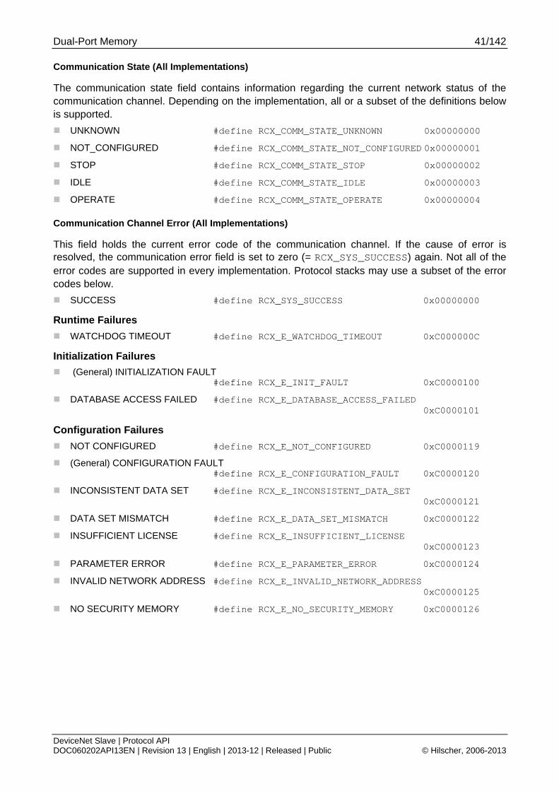
Dual-Port Memory 41/142
DeviceNet Slave | Protocol API DOC060202API13EN | Revision 13 | English | 2013-12 | Released | Public © Hilscher, 2006-2013
Communication State (All Implementations)
The communication state field contains information regarding the current network status of the communication channel. Depending on the implementation, all or a subset of the definitions below is supported.
UNKNOWN #define RCX_COMM_STATE_UNKNOWN 0x00000000
NOT_CONFIGURED #define RCX_COMM_STATE_NOT_CONFIGURED 0x00000001
STOP #define RCX_COMM_STATE_STOP 0x00000002
IDLE #define RCX_COMM_STATE_IDLE 0x00000003
OPERATE #define RCX_COMM_STATE_OPERATE 0x00000004
Communication Channel Error (All Implementations)
This field holds the current error code of the communication channel. If the cause of error is resolved, the communication error field is set to zero (= RCX_SYS_SUCCESS) again. Not all of the error codes are supported in every implementation. Protocol stacks may use a subset of the error codes below.
SUCCESS #define RCX_SYS_SUCCESS 0x00000000
Runtime Failures
WATCHDOG TIMEOUT #define RCX_E_WATCHDOG_TIMEOUT 0xC000000C
Initialization Failures
(General) INITIALIZATION FAULT #define RCX_E_INIT_FAULT 0xC0000100
DATABASE ACCESS FAILED #define RCX_E_DATABASE_ACCESS_FAILED 0xC0000101
Configuration Failures
NOT CONFIGURED #define RCX_E_NOT_CONFIGURED 0xC0000119
(General) CONFIGURATION FAULT #define RCX_E_CONFIGURATION_FAULT 0xC0000120
INCONSISTENT DATA SET #define RCX_E_INCONSISTENT_DATA_SET 0xC0000121
DATA SET MISMATCH #define RCX_E_DATA_SET_MISMATCH 0xC0000122
INSUFFICIENT LICENSE #define RCX_E_INSUFFICIENT_LICENSE 0xC0000123
PARAMETER ERROR #define RCX_E_PARAMETER_ERROR 0xC0000124
INVALID NETWORK ADDRESS #define RCX_E_INVALID_NETWORK_ADDRESS 0xC0000125
NO SECURITY MEMORY #define RCX_E_NO_SECURITY_MEMORY 0xC0000126

Dual-Port Memory 42/142
DeviceNet Slave | Protocol API DOC060202API13EN | Revision 13 | English | 2013-12 | Released | Public © Hilscher, 2006-2013
Network Failures
(General) NETWORK FAULT #define RCX_COMM_NETWORK_FAULT 0xC0000140
CONNECTION CLOSED #define RCX_COMM_CONNECTION_CLOSED 0xC0000141
CONNECTION TIMED OUT #define RCX_COMM_CONNECTION_TIMEOUT 0xC0000142
LONELY NETWORK #define RCX_COMM_LONELY_NETWORK 0xC0000143
DUPLICATE NODE #define RCX_COMM_DUPLICATE_NODE 0xC0000144
CABLE DISCONNECT #define RCX_COMM_CABLE_DISCONNECT 0xC0000145
Version (All Implementations)
The version field holds version of this structure. It starts with one; zero is not defined.
STRUCTURE VERSION #define RCX_STATUS_BLOCK_VERSION 0x0001
Watchdog Timeout (All Implementations)
This field holds the configured watchdog timeout value in milliseconds. The application may set its watchdog trigger interval accordingly. If the application fails to copy the value from the host watchdog location to the device watchdog location, the protocol stack will interrupt all network connections immediately regardless of their current state. For details, see the netX DPM Interface Manual.
Host Watchdog (All Implementations)
The protocol stack supervises the host system using the watchdog function. If the application fails to copy the value from the device watchdog location (section 3.2.5 of the netX DPM Interface Manual) to the host watchdog location (section 3.2.4 of the netX DPM Interface Manual), the protocol stack assumes that the host system has some sort of problem and shuts down all network connections. For details on the watchdog function, refer to the netX DPM Interface Manual.
Error Count (All Implementations)
This field holds the total number of errors detected since power-up, respectively after reset. The protocol stack counts all sorts of errors in this field no matter if they were network related or caused internally.
Error Log Indicator (All Implementations)
Not supported yet: The error log indicator field holds the number of entries in the internal error log. If all entries are read from the log, the field is set to zero.
3.3.1.2 Master Implementation
In addition to the common status block as outlined in the previous section, a master firmware maintains the additional structures for the administration of all slaves which are connected to the master. These are not discussed here as they are not relevant for the slave.
3.3.1.3 Slave Implementation
The slave firmware uses only the common structure as outlined in section 3.2.5.1 of the netX DPM Interface Manual for netX based Products. This is true for all protocol stacks.
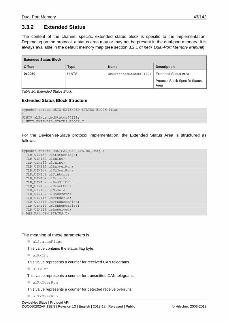
Dual-Port Memory 43/142
DeviceNet Slave | Protocol API DOC060202API13EN | Revision 13 | English | 2013-12 | Released | Public © Hilscher, 2006-2013
3.3.2 Extended Status
The content of the channel specific extended status block is specific to the implementation. Depending on the protocol, a status area may or may not be present in the dual-port memory. It is always available in the default memory map (see section 3.2.1 of netX Dual-Port Memory Manual).
Extended Status Block
Offset Type Name Description
0x0050 UINT8 abExtendedStatus[432] Extended Status Area
Protocol Stack Specific Status Area
Table 20: Extended Status Block
Extended Status Block Structure typedef struct NETX_EXTENDED_STATUS_BLOCK_Ttag { UINT8 abExtendedStatus[432]; } NETX_EXTENDED_STATUS_BLOCK_T
For the DeviceNet-Slave protocol implementation, the Extended Status Area is structured as follows:
typedef struct DNS_FAL_GEN_STATUS_Ttag { TLR_UINT32 ulStatusFlags; TLR_UINT32 ulRxInt; TLR_UINT32 ulTxInt; TLR_UINT32 ulRxOverRun; TLR_UINT32 ulTxOverRun; TLR_UINT32 ulTxAborts; TLR_UINT32 ulErrorInt; TLR_UINT32 ulBusOffCnt; TLR_UINT32 ulResetCnt; TLR_UINT32 ulNodeId; TLR_UINT32 ulBaudrate; TLR_UINT16 usVendorId; TLR_UINT16 usProducedSize; TLR_UINT16 usConsumedSize; TLR_UINT16 usReserved; } DNS_FAL_GEN_STATUS_T;
The meaning of these parameters is:
ulStatusFlags
This value contains the status flag byte.
ulRxInt
This value represents a counter for received CAN telegrams.
ulTxInt
This value represents a counter for transmitted CAN telegrams.
ulRxOverRun
This value represents a counter for detected receive overruns.
ulTxOverRun
Dual-Port Memory 44/142
DeviceNet Slave | Protocol API DOC060202API13EN | Revision 13 | English | 2013-12 | Released | Public © Hilscher, 2006-2013
This value represents a counter for detected transmission overrun events.
ulTxAborts
This value represents a counter for transmission abort events.
ulErrorInt
This value represents a counter for low transmission quality. A certain limit has been exceeded.
usBusOffCnt
This value contains the counter for bus off events.
usResetCnt
This value contains the reset counter.
ulNodeId
This value contains the own address of the Hilscher DeviceNet slave device. The allowed range extends from 0 to 63.
ulBaudrate
This value contains the chosen baud rate.
usVendorId
This value contains the Vendor ID.
usProducedSize
This value contains the number of master input bytes that are produced.
usConsumedSize
This value contains the number of master output bytes that are consumed.
usReserved
This value is reserved for future use.
Note: All counters mentioned above are initialized to the value 0 at power–up or device initialization.

Dual-Port Memory 45/142
DeviceNet Slave | Protocol API DOC060202API13EN | Revision 13 | English | 2013-12 | Released | Public © Hilscher, 2006-2013
3.4 Control Block A control block is always present within the communication channel. In some respects, control and status block are used together in order to exchange information between host application and netX firmware. The control block is written by the application, whereas the application reads a status block. Both control and status block have registers that use the Change of State mechanism (see also section 2.2.1 of the netX Dual-Port-Memory manual.).
The following gives an example of the use of control and status block. The host application wishes to lock the configuration settings of a communication channel to protect them against changes. The application sets the Lock Configuration flag in the control block to the communication channel firmware. As a result, the channel firmware sets the Configuration Locked flag in the status block (see below), indicating that the current configuration settings cannot be deleted, altered, overwritten or otherwise changed.
The control block of a dual-port memory features a watchdog function to allow the operating system running on the netX supervise the host application and vice versa. The control area is always present in the dual-port memory.
Control Block
Offset Type Name Description
0x0008 UINT32 ulApplicationCOS
Application Change Of State
State Of The Application Program
INITIALIZATION, LOCK CONFIGURATION
0x000C UINT32 ulDeviceWatchdog Device Watchdog
Host System Writes, Protocol Stack Reads
Table 21 - Communication Control Block Communication Control Block Structure typedef struct NETX_CONTROL_BLOCK_Ttag { UINT32 ulApplicationCOS; UINT32 ulDeviceWatchdog; } NETX_CONTROL_BLOCK_T;
For more information concerning the Control Block please refer to the netX DPM Interface Manual.
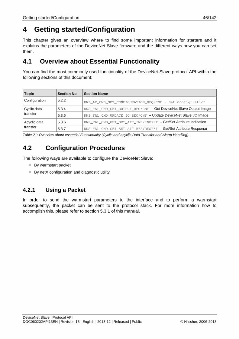
Getting started/Configuration 46/142
DeviceNet Slave | Protocol API DOC060202API13EN | Revision 13 | English | 2013-12 | Released | Public © Hilscher, 2006-2013
4 Getting started/Configuration This chapter gives an overview where to find some important information for starters and it explains the parameters of the DeviceNet Slave firmware and the different ways how you can set them.
4.1 Overview about Essential Functionality
You can find the most commonly used functionality of the DeviceNet Slave protocol API within the following sections of this document:
Topic Section No. Section Name
Configuration 5.2.2
DNS_AP_CMD_SET_CONFIGURATION_REQ/CNF – Set Configuration
5.3.4 DNS_FAL_CMD_GET_OUTPUT_REQ/CNF – Get DeviceNet Slave Output Image Cyclic data transfer 5.3.5 DNS_FAL_CMD_UPDATE_IO_REQ/CNF – Update DeviceNet Slave I/O Image
5.3.6 DNS_FAL_CMD_GET_SET_ATT_IND/INDRET – Get/Set Attribute Indication Acyclic data transfer 5.3.7 DNS_FAL_CMD_GET_SET_ATT_RES/RESRET – Get/Set Attribute Response
Table 21: Overview about essential Functionality (Cyclic and acyclic Data Transfer and Alarm Handling).
4.2 Configuration Procedures
The following ways are available to configure the DeviceNet Slave:
By warmstart packet
By netX configuration and diagnostic utility
4.2.1 Using a Packet
In order to send the warmstart parameters to the interface and to perform a warmstart subsequently, the packet can be sent to the protocol stack. For more information how to accomplish this, please refer to section 5.3.1 of this manual.

Getting started/Configuration 47/142
DeviceNet Slave | Protocol API DOC060202API13EN | Revision 13 | English | 2013-12 | Released | Public © Hilscher, 2006-2013
4.3 Warmstart Parameters
The following table contains relevant information about the warmstart parameters for the DeviceNet Slave firmware such as an explanation of the meaning of the parameter and ranges of allowed values.
These parameters are especially relevant in the context of packet DNS_FAL_CMD_APP_REQ/CNF – Register Application with DeviceNet Stack.
Warmstart Parameters
Parameter Meaning Range of Value / Value
Bus Startup The start of the device can be performed either application controlled or automatically:
Automatic:
Network connections are opened automatically without taking care of the state of the host application.
Application controlled:
The channel firmware is forced to wait for the host application to set the Application Ready flag in the communication change of state register (see section 3.2.5.1 of the netX DPM Interface Manual).
For more information concerning this topic see section “Controlled or Automatic Start” of the netX DPM Interface Manual.
Application controlled,
Automatic
I/O Status
(not yet supported)
This parameter is represented by bits 1 and 2 of the system flags.
Using this parameter you can set the status of the input or the output data. For each input and output date the following status information (in byte) is memorized in the dual-port memory.
The bits have the following meaning:
Bit 1 (I/O Status Enable):
0 = Status disabled
1 = Status enabled (not yet supported)
Bit 2 (I/O Status 8/32Bit):
0 = 1 Byte mode (not yet supported)
1 = 4 Byte mode (not yet supported)
Address Switch This parameter is represented by bit 4 of the system flags. It should be set when hardware address switch is used and there is no TAG present.
0 (off),1 (on)
Baudrate Switch This parameter is represented by bit 5 of the system flags. It should be set when hardware baudrate switch is used and there is no TAG present.
0 (off),1 (on)
Watchdog Time [ms] Watchdog time within which the device watchdog must be retriggered from the application program while the application program monitoring is activated. When the watchdog time value is equal to 0 respectively the application program monitoring is deactivated.
[0, 20 … 65535] ms, default = 1000 ms, 0 = Off
Node ID This parameter defines the DNS-Task DeviceNet address of the node (Node ID or MAC ID) within the network.
Allowed values: 0 – 63
Baudrate Baud rate of DeviceNet connection. Coding see Table 23: Available Baud Rate Valuesbelow!
Allowed values: all baud rates offered in Table 23.
Default value: 0
ProducedSize ProducedSize sets the number of input bytes the DNS-Task will produce in the view of a master for each established connection.
Allowed values: 0 – 255
Default value: 2
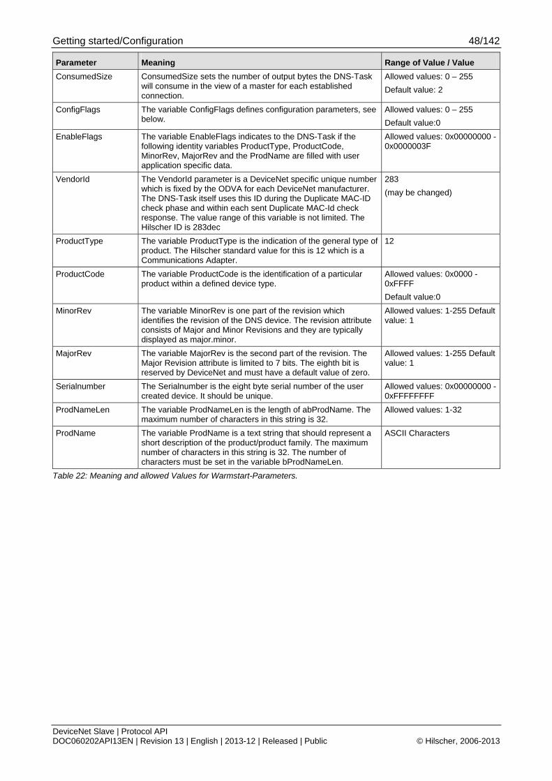
Getting started/Configuration 48/142
DeviceNet Slave | Protocol API DOC060202API13EN | Revision 13 | English | 2013-12 | Released | Public © Hilscher, 2006-2013
Parameter Meaning Range of Value / Value
ConsumedSize ConsumedSize sets the number of output bytes the DNS-Task will consume in the view of a master for each established connection.
Allowed values: 0 – 255
Default value: 2
ConfigFlags The variable ConfigFlags defines configuration parameters, see below.
Allowed values: 0 – 255
Default value:0
EnableFlags The variable EnableFlags indicates to the DNS-Task if the following identity variables ProductType, ProductCode, MinorRev, MajorRev and the ProdName are filled with user application specific data.
Allowed values: 0x00000000 - 0x0000003F
VendorId The VendorId parameter is a DeviceNet specific unique number which is fixed by the ODVA for each DeviceNet manufacturer. The DNS-Task itself uses this ID during the Duplicate MAC-ID check phase and within each sent Duplicate MAC-Id check response. The value range of this variable is not limited. The Hilscher ID is 283dec
283
(may be changed)
ProductType The variable ProductType is the indication of the general type of product. The Hilscher standard value for this is 12 which is a Communications Adapter.
12
ProductCode The variable ProductCode is the identification of a particular product within a defined device type.
Allowed values: 0x0000 - 0xFFFF
Default value:0
MinorRev The variable MinorRev is one part of the revision which identifies the revision of the DNS device. The revision attribute consists of Major and Minor Revisions and they are typically displayed as major.minor.
Allowed values: 1-255 Default value: 1
MajorRev The variable MajorRev is the second part of the revision. The Major Revision attribute is limited to 7 bits. The eighth bit is reserved by DeviceNet and must have a default value of zero.
Allowed values: 1-255 Default value: 1
Serialnumber The Serialnumber is the eight byte serial number of the user created device. It should be unique.
Allowed values: 0x00000000 - 0xFFFFFFFF
ProdNameLen The variable ProdNameLen is the length of abProdName. The maximum number of characters in this string is 32.
Allowed values: 1-32
ProdName The variable ProdName is a text string that should represent a short description of the product/product family. The maximum number of characters in this string is 32. The number of characters must be set in the variable bProdNameLen.
ASCII Characters
Table 22: Meaning and allowed Values for Warmstart-Parameters.
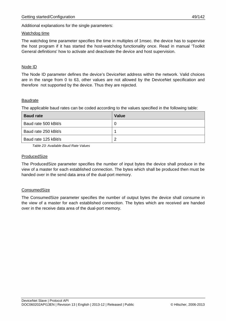
Getting started/Configuration 49/142
DeviceNet Slave | Protocol API DOC060202API13EN | Revision 13 | English | 2013-12 | Released | Public © Hilscher, 2006-2013
Additional explanations for the single parameters:
Watchdog time
The watchdog time parameter specifies the time in multiples of 1msec. the device has to supervise the host program if it has started the host-watchdog functionality once. Read in manual 'Toolkit General definitions' how to activate and deactivate the device and host supervision.
Node ID
The Node ID parameter defines the device’s DeviceNet address within the network. Valid choices are in the range from 0 to 63, other values are not allowed by the DeviceNet specification and therefore not supported by the device. Thus they are rejected.
Baudrate
The applicable baud rates can be coded according to the values specified in the following table:
Baud rate Value
Baud rate 500 kBit/s 0
Baud rate 250 kBit/s 1
Baud rate 125 kBit/s 2
Table 23: Available Baud Rate Values
ProducedSize
The ProducedSize parameter specifies the number of input bytes the device shall produce in the view of a master for each established connection. The bytes which shall be produced then must be handed over in the send data area of the dual-port memory.
ConsumedSize
The ConsumedSize parameter specifies the number of output bytes the device shall consume in the view of a master for each established connection. The bytes which are received are handed over in the receive data area of the dual-port memory.
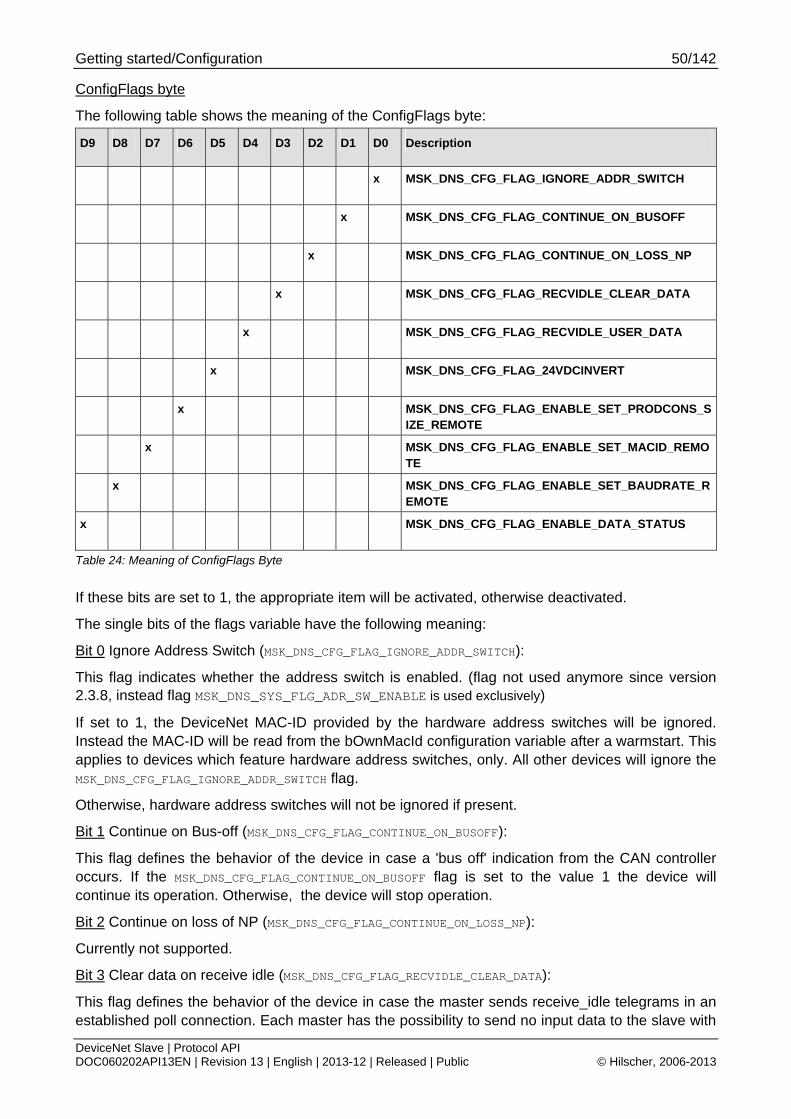
Getting started/Configuration 50/142
DeviceNet Slave | Protocol API DOC060202API13EN | Revision 13 | English | 2013-12 | Released | Public © Hilscher, 2006-2013
ConfigFlags byte
The following table shows the meaning of the ConfigFlags byte:
D9 D8 D7 D6 D5 D4 D3 D2 D1 D0 Description
x MSK_DNS_CFG_FLAG_IGNORE_ADDR_SWITCH
x MSK_DNS_CFG_FLAG_CONTINUE_ON_BUSOFF
x MSK_DNS_CFG_FLAG_CONTINUE_ON_LOSS_NP
x MSK_DNS_CFG_FLAG_RECVIDLE_CLEAR_DATA
x MSK_DNS_CFG_FLAG_RECVIDLE_USER_DATA
x MSK_DNS_CFG_FLAG_24VDCINVERT
x MSK_DNS_CFG_FLAG_ENABLE_SET_PRODCONS_SIZE_REMOTE
x MSK_DNS_CFG_FLAG_ENABLE_SET_MACID_REMOTE
x MSK_DNS_CFG_FLAG_ENABLE_SET_BAUDRATE_REMOTE
x MSK_DNS_CFG_FLAG_ENABLE_DATA_STATUS
Table 24: Meaning of ConfigFlags Byte
If these bits are set to 1, the appropriate item will be activated, otherwise deactivated.
The single bits of the flags variable have the following meaning:
Bit 0 Ignore Address Switch (MSK_DNS_CFG_FLAG_IGNORE_ADDR_SWITCH):
This flag indicates whether the address switch is enabled. (flag not used anymore since version 2.3.8, instead flag MSK_DNS_SYS_FLG_ADR_SW_ENABLE is used exclusively)
If set to 1, the DeviceNet MAC-ID provided by the hardware address switches will be ignored. Instead the MAC-ID will be read from the bOwnMacId configuration variable after a warmstart. This applies to devices which feature hardware address switches, only. All other devices will ignore the MSK_DNS_CFG_FLAG_IGNORE_ADDR_SWITCH flag.
Otherwise, hardware address switches will not be ignored if present.
Bit 1 Continue on Bus-off (MSK_DNS_CFG_FLAG_CONTINUE_ON_BUSOFF):
This flag defines the behavior of the device in case a 'bus off' indication from the CAN controller occurs. If the MSK_DNS_CFG_FLAG_CONTINUE_ON_BUSOFF flag is set to the value 1 the device will continue its operation. Otherwise, the device will stop operation.
Bit 2 Continue on loss of NP (MSK_DNS_CFG_FLAG_CONTINUE_ON_LOSS_NP):
Currently not supported.
Bit 3 Clear data on receive idle (MSK_DNS_CFG_FLAG_RECVIDLE_CLEAR_DATA):
This flag defines the behavior of the device in case the master sends receive_idle telegrams in an established poll connection. Each master has the possibility to send no input data to the slave with
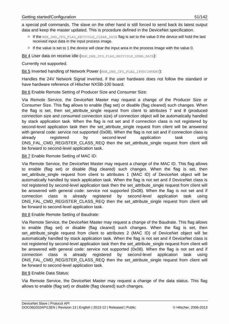
Getting started/Configuration 51/142
DeviceNet Slave | Protocol API DOC060202API13EN | Revision 13 | English | 2013-12 | Released | Public © Hilscher, 2006-2013
a special poll commands. The slave on the other hand is still forced to send back its latest output data and keep the master updated. This is procedure defined in the DeviceNet specification.
If the MSK_DNS_CFG_FLAG_RECVIDLE_CLEAR_DATA flag is set to the value 0 the device will hold the last received input data in the input process image.
If the value is set to 1 the device will clear the input area in the process image with the value 0.
Bit 4 User data on receive idle (MSK_DNS_CFG_FLAG_RECVIDLE_USER_DATA):
Currently not supported.
Bit 5 Inverted handling of Network Power (MSK_DNS_CFG_FLAG_24VDCINVERT):
Handles the 24V Network Signal inverted, if the user hardware does not follow the standard or have hardware reference of Hilscher NXSB-100 board.
Bit 6 Enable Remote Setting of Producer Size and Consumer Size:
Via Remote Service, the DeviceNet Master may request a change of the Producer Size or Consumer Size. This flag allows to enable (flag set) or disable (flag cleared) such changes. When the flag is set, then set_attribute_single request from client to attributes 7 and 8 (produced connection size and consumed connection size) of connection object will be automatically handled by stack application task. When the flag is not set and if connection class is not registered by second-level application task then the set_attribute_single request from client will be answered with general code: service not supported (0x08). When the flag is not set and if connection class is already registered by second-level application task using DNS_FAL_CMD_REGISTER_CLASS_REQ then the set_attribute_single request from client will be forward to second-level application task.
Bit 7 Enable Remote Setting of MAC ID:
Via Remote Service, the DeviceNet Master may request a change of the MAC ID. This flag allows to enable (flag set) or disable (flag cleared) such changes. When the flag is set, then set_attribute_single request from client to attributes 1 (MAC ID) of DeviceNet object will be automatically handled by stack application task. When the flag is not set and if DeviceNet class is not registered by second-level application task then the set_attribute_single request from client will be answered with general code: service not supported (0x08). When the flag is not set and if connection class is already registered by second-level application task using DNS_FAL_CMD_REGISTER_CLASS_REQ then the set_attribute_single request from client will be forward to second-level application task.
Bit 8 Enable Remote Setting of Baudrate:
Via Remote Service, the DeviceNet Master may request a change of the Baudrate. This flag allows to enable (flag set) or disable (flag cleared) such changes. When the flag is set, then set_attribute_single request from client to attributes 2 (MAC ID) of DeviceNet object will be automatically handled by stack application task. When the flag is not set and if DeviceNet class is not registered by second-level application task then the set_attribute_single request from client will be answered with general code: service not supported (0x08). When the flag is not set and if connection class is already registered by second-level application task using DNS_FAL_CMD_REGISTER_CLASS_REQ then the set_attribute_single request from client will be forward to second-level application task.
Bit 9 Enable Data Status:
Via Remote Service, the DeviceNet Master may request a change of the data status. This flag allows to enable (flag set) or disable (flag cleared) such changes.
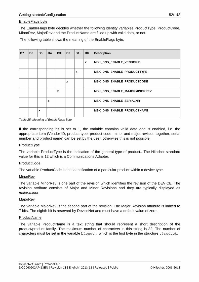
Getting started/Configuration 52/142
DeviceNet Slave | Protocol API DOC060202API13EN | Revision 13 | English | 2013-12 | Released | Public © Hilscher, 2006-2013
EnableFlags byte
The EnableFlags byte decides whether the following identity variables ProductType, ProductCode, MinorRev, MajorRev and the ProductName are filled up with valid data, or not.
The following table shows the meaning of the EnableFlags byte:
D7 D6 D5 D4 D3 D2 D1 D0 Description
x MSK_DNS_ENABLE_VENDORID
x MSK_DNS_ENABLE_PRODUCTTYPE
x MSK_DNS_ENABLE_PRODUCTCODE
x MSK_DNS_ENABLE_MAJORMINORREV
x MSK_DNS_ENABLE_SERIALNR
x MSK_DNS_ENABLE_PRODUCTNAME
Table 25: Meaning of EnableFlags Byte
If the corresponding bit is set to 1, the variable contains valid data and is enabled, i.e. the appropriate item (Vendor ID, product type, product code, minor and major revision together, serial number and product name) can be set by the user, otherwise this is not possible.
ProductType
The variable ProductType is the indication of the general type of product.. The Hilscher standard value for this is 12 which is a Communications Adapter.
ProductCode
The variable ProductCode is the identification of a particular product within a device type.
MinorRev
The variable MinorRev is one part of the revision which identifies the revision of the DEVICE. The revision attribute consists of Major and Minor Revisions and they are typically displayed as major.minor.
MajorRev
The variable MajorRev is the second part of the revision. The Major Revision attribute is limited to 7 bits. The eighth bit is reserved by DeviceNet and must have a default value of zero.
ProductName
The variable ProductName is a text string that should represent a short description of the product/product family. The maximum number of characters in this string is 32. The number of characters must be set in the variable bLength which is the first byte in the structure tProduct.

Getting started/Configuration 53/142
DeviceNet Slave | Protocol API DOC060202API13EN | Revision 13 | English | 2013-12 | Released | Public © Hilscher, 2006-2013
4.3.1 Behavior when receiving a Set Configuration / Warmstart Command
The following rules apply for the behavior of the DeviceNet Slave protocol stack when receiving a set configuration command:
The configuration packets name is DNS_AP_CMD_SET_CONFIGURATION_REQ for the request and DNS_AP_CMD_SET_CONFIGURATION_CNF for the confirmation.
The configuration data are checked for consistency and integrity.
In case of failure no data are accepted.
In case of success the configuration parameters are stored internally (within the RAM).
The parameterized data will be activated only after a channel init has been performed.
No automatic registration of the application at the stack happens.
The confirmation packet DNS_AP_CMD_SET_CONFIGURATION_CNF only transfers simple status information, but does not repeat the whole parameter set.
For all former versions up to firmware version V2.0.1, only the warmstart command (the predecessor of the set configuration command) was present showing up the following deviations from the behavior described above:
1. Contrary to the situation when receiving a set configuration command, on every received warmstart packet an automatic channel-init is performed.
2. The stack automatically starts up at the first configuration attempt if correct data are supplied.
3. Every attempt to send another additional DNS_AP_CMD_SET_CONFIGURATION_REQ packet (for instance, in order to change the configuration) will be rejected. This means the DeviceNet Slave protocol stack is in these versions is not reconfigurable.
4.4 Process Data (Input and Output)
The input and output data area is divided into the following sections:
Input and Output Data for DeviceNet Slave
I/O Offset Area Length (Byte) Type
0x1000 Output block 255 Read/Write
0x2680 Input block 255 Read
Table 26: Input and Output Data
Getting started/Configuration 54/142
DeviceNet Slave | Protocol API DOC060202API13EN | Revision 13 | English | 2013-12 | Released | Public © Hilscher, 2006-2013
4.5 Task Structure of the DeviceNet Slave Stack
In detail, the various tasks have the following functionality and responsibilities:
Second-Level Application Task (User Application Task or Host Application Task) is optional
User-implemented application task. This task handles further requirements like device profile implementation or some other advanced/customized handling of data exchange.
DNS App Task (a.k.a. DNS Stack Application Task)
The DNS AP-Task contains the process queue which handles all incoming and outgoing packets from the user application. It provides the communication channel for the underlying DNS FAL stack. Once, the stack communication is established, mailbox packets are sent to the AP task’s process queue. Every packet is evaluated in the AP-Task’s context and corresponding actions are executed. The AP task is the user interface to the DNS FAL stack.
DNS FAL Task
The DNS FAL-Task is the DeviceNet protocol stack. This task handles all aspects of the DeviceNet protocol. Application packets sent from the AP-Task are processed through the internal process queue. Once configured by the AP-Task the DNS FAL-Task will handle all DeviceNet communications like cyclic I/O message processing and acyclic messaging. This task provides acyclic messaging to the AP-Task through mailbox indication packets.
CAN DL Task
The CAN DL Task handlers all process queue information between the DNS FAL Task and the underlying CAN hardware layer driver. An interface to this task is not available via the AP task.
The User Application Interface 55/142
DeviceNet Slave | Protocol API DOC060202API13EN | Revision 13 | English | 2013-12 | Released | Public © Hilscher, 2006-2013
5 The User Application Interface This chapter defines the user application interface of the DeviceNet-Slave Stack. There are two different levels the user can access the DeviceNet-Slave stack.
The Communication Channel Interface via Dual port Memory
The DeviceNet Slave - Task Interface
The Communication Channel Interface is the Hilscher’s Dual port Memory Interface for field buses or other communication stacks. A typical application is when using PC cards or COM modules with a discrete DPM and accessing the DeviceNet-Slave via Driver API. This Interface is also available, when a user develops its own application within the netX system and works with the virtual DPM system intern.
The second level is when a user implements its own application task direct over the DevNetFAL Task. Then a user has to care the configuration process, mapping I/O data and status information by its own. Typically when a user works with its own dual port memory layout. The application itself has to be developed then as a task according to the Hilscher’s Task Layer Reference Model.
Note: All packets described in this chapter can be used both when working with loadable firmware and with linkable object modules.
5.1 The Dual Port Memory Interface
This chapter defines the user interface functions available when using the Dual Port Memory to interface to the DeviceNet Slave Stack.
The user application developed for the Dual Ported Memory interface should follow the details outlined in the “netX DPM Interface Manual”.
The following chapter defines the packets which may be sent or received by the user using the Dual Port Memory Interface method.
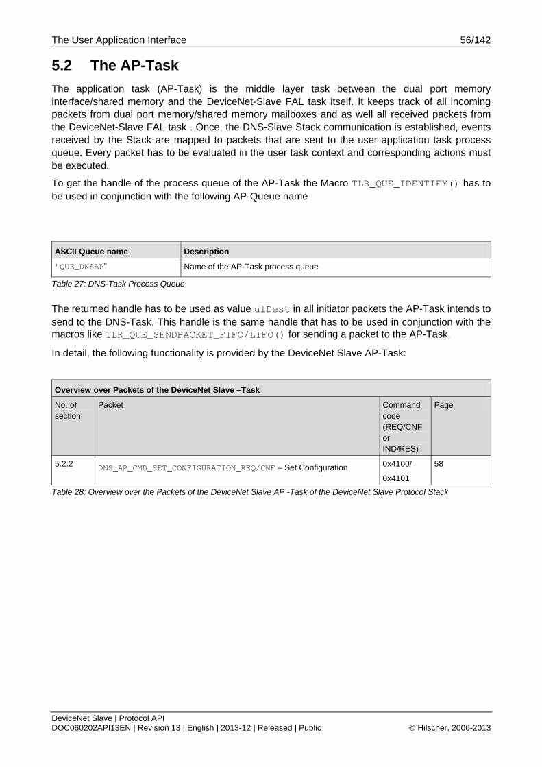
The User Application Interface 56/142
DeviceNet Slave | Protocol API DOC060202API13EN | Revision 13 | English | 2013-12 | Released | Public © Hilscher, 2006-2013
5.2 The AP-Task
The application task (AP-Task) is the middle layer task between the dual port memory interface/shared memory and the DeviceNet-Slave FAL task itself. It keeps track of all incoming packets from dual port memory/shared memory mailboxes and as well all received packets from the DeviceNet-Slave FAL task . Once, the DNS-Slave Stack communication is established, events received by the Stack are mapped to packets that are sent to the user application task process queue. Every packet has to be evaluated in the user task context and corresponding actions must be executed.
To get the handle of the process queue of the AP-Task the Macro TLR_QUE_IDENTIFY() has to be used in conjunction with the following AP-Queue name
ASCII Queue name Description
"QUE_DNSAP” Name of the AP-Task process queue
Table 27: DNS-Task Process Queue
The returned handle has to be used as value ulDest in all initiator packets the AP-Task intends to send to the DNS-Task. This handle is the same handle that has to be used in conjunction with the macros like TLR_QUE_SENDPACKET_FIFO/LIFO() for sending a packet to the AP-Task.
In detail, the following functionality is provided by the DeviceNet Slave AP-Task:
Overview over Packets of the DeviceNet Slave –Task
No. of section
Packet Command code (REQ/CNF or IND/RES)
Page
5.2.2
DNS_AP_CMD_SET_CONFIGURATION_REQ/CNF – Set Configuration 0x4100/
0x4101
58
Table 28: Overview over the Packets of the DeviceNet Slave AP -Task of the DeviceNet Slave Protocol Stack
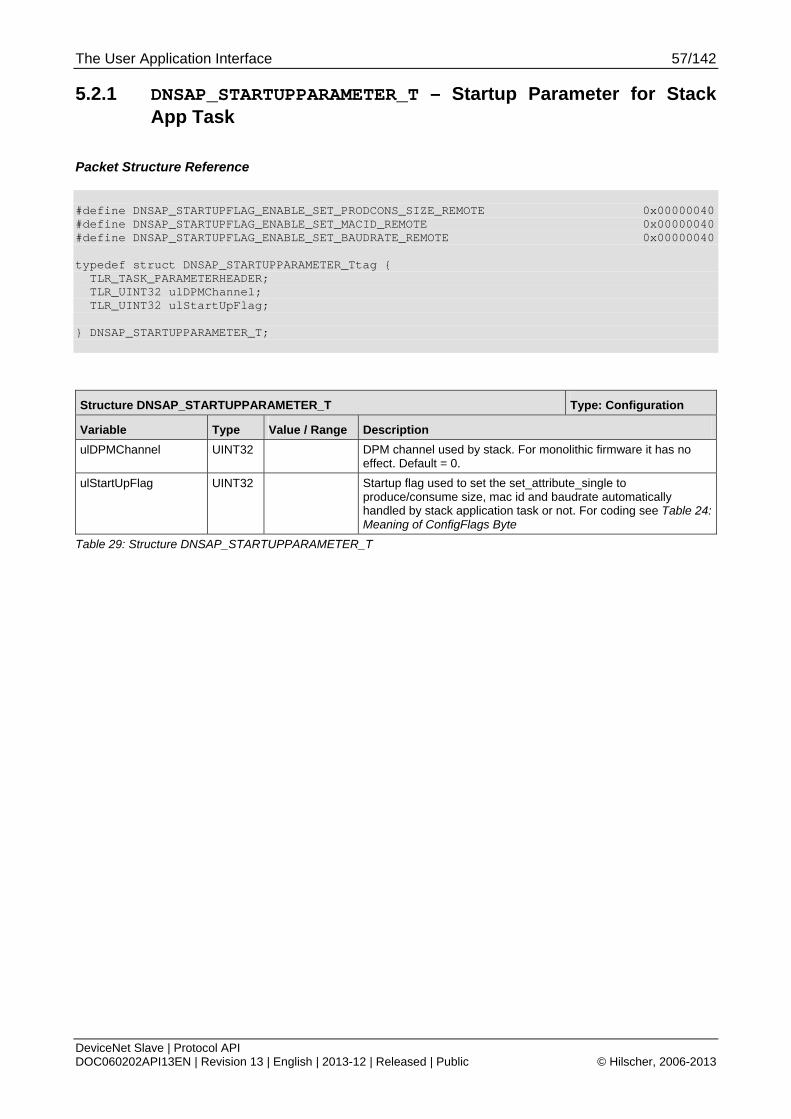
The User Application Interface 57/142
DeviceNet Slave | Protocol API DOC060202API13EN | Revision 13 | English | 2013-12 | Released | Public © Hilscher, 2006-2013
5.2.1 DNSAP_STARTUPPARAMETER_T – Startup Parameter for Stack App Task
Packet Structure Reference
#define DNSAP_STARTUPFLAG_ENABLE_SET_PRODCONS_SIZE_REMOTE 0x00000040 #define DNSAP_STARTUPFLAG_ENABLE_SET_MACID_REMOTE 0x00000040 #define DNSAP_STARTUPFLAG_ENABLE_SET_BAUDRATE_REMOTE 0x00000040 typedef struct DNSAP_STARTUPPARAMETER_Ttag { TLR_TASK_PARAMETERHEADER; TLR_UINT32 ulDPMChannel; TLR_UINT32 ulStartUpFlag; } DNSAP_STARTUPPARAMETER_T;
Structure DNSAP_STARTUPPARAMETER_T Type: Configuration
Variable Type Value / Range Description
ulDPMChannel UINT32 DPM channel used by stack. For monolithic firmware it has no effect. Default = 0.
ulStartUpFlag UINT32 Startup flag used to set the set_attribute_single to produce/consume size, mac id and baudrate automatically handled by stack application task or not. For coding see Table 24: Meaning of ConfigFlags Byte
Table 29: Structure DNSAP_STARTUPPARAMETER_T
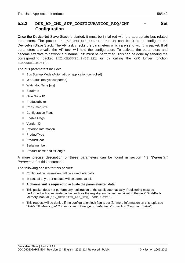
The User Application Interface 58/142
DeviceNet Slave | Protocol API DOC060202API13EN | Revision 13 | English | 2013-12 | Released | Public © Hilscher, 2006-2013
5.2.2 DNS_AP_CMD_SET_CONFIGURATION_REQ/CNF – Set Configuration
Once the DeviceNet Slave Stack is started, it must be initialized with the appropriate bus related parameters. The packet DNS_AP_CMD_SET_CONFIGURATION can be used to configure the DeviceNet-Slave Stack. The AP task checks the parameters which are send with this packet. If all parameters are valid the AP task will hold the configuration. To activate the parameters and become effective to network a “Channel Init” must be performed. This can be done by sending the corresponding packet RCX_CHANNEL_INIT_REQ or by calling the cifX Driver function xChannelInit().
The bus parameters include:
Bus Startup Mode (Automatic or application-controlled)
I/O Status (not yet supported)
Watchdog Time [ms]
Baudrate
Own Node ID
ProducedSize
ConsumedSize
Configuration Flags
Enable Flags
Vendor ID
Revision Information
ProductType
ProductCode
Serial number
Product name and its length
A more precise description of these parameters can be found in section 4.3 “Warmstart Parameters” of this document.
The following applies for this packet:
Configuration parameters will be stored internally.
In case of any error no data will be stored at all.
A channel init is required to activate the parameterized data.
This packet does not perform any registration at the stack automatically. Registering must be performed with a separate packet such as the registration packet described in the netX Dual-Port-Memory Manual (RCX_REGISTER_APP_REQ, code 0x2F10).
This request will be denied if the configuration lock flag is set (for more information on this topic see “Table 19: Meaning of Communication Change of State Flags” in section “Common Status”).
The User Application Interface 59/142
DeviceNet Slave | Protocol API DOC060202API13EN | Revision 13 | English | 2013-12 | Released | Public © Hilscher, 2006-2013
Note: The command DNS_AP_CMD_SET_CONFIGURATION_REQ is mapped to the command DNS_FAL_CMD_INIT_STACK_REQ. The differences are in the command number and the behavior when the parameters become effective to the network. The parameters which are sent with DNS_FAL_CMD_INIT_STACK_REQ become effective immediately. The parameters set with the command DNS_AP_CMD_SET_CONFIGURATION_REQ become effective after a following “Channel Init”.
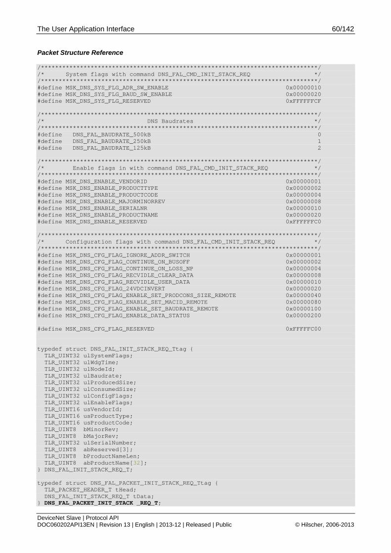
The User Application Interface 60/142
DeviceNet Slave | Protocol API DOC060202API13EN | Revision 13 | English | 2013-12 | Released | Public © Hilscher, 2006-2013
Packet Structure Reference
/******************************************************************************/ /* System flags with command DNS_FAL_CMD_INIT_STACK_REQ */ /******************************************************************************/ #define MSK_DNS_SYS_FLG_ADR_SW_ENABLE 0x00000010 #define MSK_DNS_SYS_FLG_BAUD_SW_ENABLE 0x00000020 #define MSK_DNS_SYS_FLG_RESERVED 0xFFFFFFCF /******************************************************************************/ /* DNS Baudrates */ /******************************************************************************/ #define DNS_FAL_BAUDRATE_500kB 0 #define DNS_FAL_BAUDRATE_250kB 1 #define DNS_FAL_BAUDRATE_125kB 2 /******************************************************************************/ /* Enable flags in with command DNS_FAL_CMD_INIT_STACK_REQ */ /******************************************************************************/ #define MSK_DNS_ENABLE_VENDORID 0x00000001 #define MSK_DNS_ENABLE_PRODUCTTYPE 0x00000002 #define MSK_DNS_ENABLE_PRODUCTCODE 0x00000004 #define MSK_DNS_ENABLE_MAJORMINORREV 0x00000008 #define MSK_DNS_ENABLE_SERIALNR 0x00000010 #define MSK_DNS_ENABLE_PRODUCTNAME 0x00000020 #define MSK_DNS_ENABLE_RESERVED 0xFFFFFFC0 /******************************************************************************/ /* Configuration flags with command DNS_FAL_CMD_INIT_STACK_REQ */ /******************************************************************************/ #define MSK_DNS_CFG_FLAG_IGNORE_ADDR_SWITCH 0x00000001 #define MSK_DNS_CFG_FLAG_CONTINUE_ON_BUSOFF 0x00000002 #define MSK_DNS_CFG_FLAG_CONTINUE_ON_LOSS_NP 0x00000004 #define MSK_DNS_CFG_FLAG_RECVIDLE_CLEAR_DATA 0x00000008 #define MSK_DNS_CFG_FLAG_RECVIDLE_USER_DATA 0x00000010 #define MSK_DNS_CFG_FLAG_24VDCINVERT 0x00000020 #define MSK_DNS_CFG_FLAG_ENABLE_SET_PRODCONS_SIZE_REMOTE 0x00000040 #define MSK_DNS_CFG_FLAG_ENABLE_SET_MACID_REMOTE 0x00000080 #define MSK_DNS_CFG_FLAG_ENABLE_SET_BAUDRATE_REMOTE 0x00000100 #define MSK_DNS_CFG_FLAG_ENABLE_DATA_STATUS 0x00000200 #define MSK_DNS_CFG_FLAG_RESERVED 0xFFFFFC00 typedef struct DNS_FAL_INIT_STACK_REQ_Ttag { TLR_UINT32 ulSystemFlags; TLR_UINT32 ulWdgTime; TLR_UINT32 ulNodeId; TLR_UINT32 ulBaudrate; TLR_UINT32 ulProducedSize; TLR_UINT32 ulConsumedSize; TLR_UINT32 ulConfigFlags; TLR_UINT32 ulEnableFlags; TLR_UINT16 usVendorId; TLR_UINT16 usProductType; TLR_UINT16 usProductCode; TLR_UINT8 bMinorRev; TLR_UINT8 bMajorRev; TLR_UINT32 ulSerialNumber; TLR_UINT8 abReserved[3]; TLR_UINT8 bProductNameLen; TLR_UINT8 abProductName[32]; } DNS_FAL_INIT_STACK_REQ_T; typedef struct DNS_FAL_PACKET_INIT_STACK_REQ_Ttag { TLR_PACKET_HEADER_T tHead; DNS_FAL_INIT_STACK_REQ_T tData; } DNS_FAL_PACKET_INIT_STACK _REQ_T;

The User Application Interface 61/142
DeviceNet Slave | Protocol API DOC060202API13EN | Revision 13 | English | 2013-12 | Released | Public © Hilscher, 2006-2013
Packet Description
Structure DNS_FAL_PACKET_INIT_STACK_REQ_T Type: Request
Variable Type Value / Range Description
tHead - Structure TLR_PACKET_HEADER_T
ulDest UINT32 Destination Queue-Handle of DNS-Task Process Queue
ulSrc UINT32 Source Queue-Handle of AP-Task Process Queue
ulDestId UINT32 0 Destination End Point Identifier, specifying the final receiver of the packet within the Destination Process. Set to 0 for the Initialization Packet
ulSrcId UINT32 0 ... 232-1 Source End Point Identifier, specifying the origin of the packet inside the Source Process
ulLen UINT32 80 sizeof(DNS_FAL_INIT_STACK_REQ_T)
ulId UINT32 0 ... 232-1 Packet Identification as unique number generated by the Source Process of the Packet
ulSta UINT32 See section 6.1 Error Codes of the FAL-Task
ulCmd UINT32 0x4100 DNS_AP_CMD_SET_CONFIGURATION_REQ - Command
ulExt UINT32 0 Extension not in use, set to zero for compatibility reasons
ulRout UINT32 × Routing, do not touch
tData - Structure DNS_FAL_INIT_STACK_REQ_T
ulSystemFlags UINT32 0
1
System Flags:
BIT 0: AUTOSTART / APPLICATION CONTROLLED
communication with a controller after a device start is allowed without BUS_ON flag, but the communication will be interrupted if the BUS_ON flag changes state to 0
communication with controller is allowed only with the BUS_ON flag.
BIT 1: I/O STATUS DISABLED/ ENABLED
Not supported yet
BIT 2: IO STATUS 32 BIT
Not supported yet
BIT 3: Reserved for further use, set to zero
BIT 4: ADDRESS_SWITCH
Should be set when hardware address switch is used and there is no TAG present.
BIT 5: BAUD_SWITCH
Should be set when hardware baudrate switch is used and there is no TAG present.
BIT 6 - 31: Reserved for further use, set to zero
ulWdgTime UINT32 0, 20-65535 The parameter ulWdgTime sets the watchdog time in multiples of 1msec. This time is the period of which the DNS-Task will supervise the AP-Task. 0 indicates the watchdog has been switched off.
ulNodeId UINT32 0-63 The parameter bMacId defines the DNS-Task DeviceNet address within the network. Valid rages are 0-63, other values not supported by DeviceNet and the DNS-Task are rejected.
ulBaudrate UINT32 0 - 2 The parameter ulBaudrate sets the current baud rate to be used by the DNS-Task.
For coding see Table 23: Available Baud Rate Values
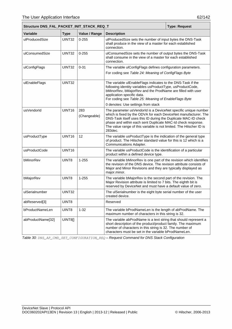
The User Application Interface 62/142
DeviceNet Slave | Protocol API DOC060202API13EN | Revision 13 | English | 2013-12 | Released | Public © Hilscher, 2006-2013
Structure DNS_FAL_PACKET_INIT_STACK_REQ_T Type: Request
Variable Type Value / Range Description
ulProducedSize UINT32 0-255 ulProducedSize sets the number of input bytes the DNS-Task shall produce in the view of a master for each established connection.
ulConsumedSize UINT32 0-255 ulConsumedSize sets the number of output bytes the DNS-Task shall consume in the view of a master for each established connection.
ulConfigFlags UINT32 0-31
The variable ulConfigFlags defines configuration parameters.
For coding see Table 24: Meaning of ConfigFlags Byte
ulEnableFlags UINT32 The variable ulEnableFlags indicates to the DNS-Task if the following identity variables usProductType, usProductCode, bMinorRev, bMajorRev and the ProdName are filled with user application specific data. For coding see Table 25: Meaning of EnableFlags Byte
0 denotes: Use settings from stack
usVendorId UINT16 283
(Changeable)
The parameter usVendorId is a DeviceNet specific unique number which is fixed by the ODVA for each DeviceNet manufacturer. The DNS-Task itself uses this ID during the Duplicate MAC-ID check phase and within each sent Duplicate MAC-Id check response. The value range of this variable is not limited. The Hilscher ID is 283dec.
usProductType UINT16 12 The variable usProductType is the indication of the general type of product. The Hilscher standard value for this is 12 which is a Communications Adapter.
usProductCode UINT16 The variable usProductCode is the identification of a particular product within a defined device type.
bMinorRev UINT8 1-255 The variable bMinorRev is one part of the revision which identifies the revision of the DNS device. The revision attribute consists of Major and Minor Revisions and they are typically displayed as major.minor.
bMajorRev UINT8 1-255 The variable bMajorRev is the second part of the revision. The Major Revision attribute is limited to 7 bits. The eighth bit is reserved by DeviceNet and must have a default value of zero.
ulSerialnumber UINT32 The ulSerialnumber is the eight byte serial number of the user created device.
abReserved[3] UINT8 Reserved
bProductNameLen UINT8 1-32 The variable bProdNameLen is the length of abProdName. The maximum number of characters in this string is 32.
abProductName[32] UINT8[] The variable abProdName is a text string that should represent a short description of the product/product family. The maximum number of characters in this string is 32. The number of characters must be set in the variable bProdNameLen.
Table 30: DNS_AP_CMD_SET_CONFIGURATION_REQ – Request Command for DNS Stack Configuration

The User Application Interface 63/142
DeviceNet Slave | Protocol API DOC060202API13EN | Revision 13 | English | 2013-12 | Released | Public © Hilscher, 2006-2013
Source Code Example
TLR_RESULT DnsApp_SetConfig_Req(DNS_APP_RSC_T FAR* ptRsc) { TLR_RESULT eRslt; DNS_AP_PACKET_SET_CONFIGURATION_REQ_T *ptInitStackReq; eRslt = TLR_POOL_PACKET_GET(ptRsc->tLoc.hPool, &ptInitStackReq); if( eRslt == TLR_S_OK ) { TLR_QUE_LINK_SET_PACKET_SRC(ptInitStackReq,ptRsc->tLoc.tQueSrcDnsApp); ptInitStackReq->tHead.ulCmd = DNS_AP_CMD_SET_CONFIGURATION_REQ; ptInitStackReq->tHead.ulLen = sizeof(DNS_FAL_SET_CONFIGURATION_REQ_T); /* Set the slave related parameters here */ ptInitStackReq->tData.ulSystemFlags = 0; ptInitStackReq->tData.ulWdgTime = 0; ptInitStackReq->tData.ulNodeId = 11; ptInitStackReq->tData.ulBaudrate = DNS_FAL_BAUDRATE_125kB; ptInitStackReq->tData.ulProducedSize = 8; ptInitStackReq->tData.ulConsumedSize = 8; ptInitStackReq->tData.ulConfigFlags = 0; ptInitStackReq->tData.ulEnableFlags = MSK_DNS_ENABLE_VENDORID | MSK_DNS_ENABLE_PRODUCTTYPE | MSK_DNS_ENABLE_PRODUCTCODE | MSK_DNS_ENABLE_PRODUCTNAME | MSK_DNS_ENABLE_SERIALNR; ptInitStackReq->tData.usVendorId = 283; /* My VendorId */ ptInitStackReq->tData.usProductType = 12; /* My Producttype */ ptInitStackReq->tData.usProductCode = 1; /* My Productcode */ ptInitStackReq->tData.bMajorRev = 0; /* Not enabled use stack default */ ptInitStackReq->tData.bMinorRev = 0; /* Not enabled use stack default */ TLR_MEMCPY(&ptInitStackReq->tData.abProductName[0],"My netX DNS",11); ptInitStackReq->tData.bProductNameLen = 11; ptInitStackReq->tData.ulSerialnumber = 0x11223344L; eRslt = TLR_QUE_SENDPACKET_FIFO(ptRsc >tLoc.tDnsQue,ptInitStackReq,TLR_FINITE); if( eRslt != TLR_S_OK ) { TLR_POOL_PACKET_RELEASE(ptRsc->tLoc.hPool, ptInitStackReq); } } return eRslt; }

The User Application Interface 64/142
DeviceNet Slave | Protocol API DOC060202API13EN | Revision 13 | English | 2013-12 | Released | Public © Hilscher, 2006-2013
Packet Structure Reference
/******************************************************************************/ /* DNS_FAL_CMD_INIT_STACK_CNF Structure */ /******************************************************************************/ typedef struct DNS_FAL_INIT_STACK_CNF_Ttag { TLR_HANDLE hPdOutTrpBuf; TLR_HANDLE hPdInTrpBuf; } DNS_FAL_INIT_STACK_CNF_T; typedef struct DNS_FAL_PACKET_INIT_STACK_CNF_Ttag { TLR_PACKET_HEADER_T tHead; DNS_FAL_INIT_STACK_CNF_T tData; } DNS_FAL_PACKET_INIT_STACK_CNF_T;
Packet Description
Structure DNS_FAL_PACKET_INIT_STACK_CNF_T Type: Confirmation
Variable Type Value / Range Description
tHead - Structure TLR_PACKET_HEADER_T
ulDest UINT32 Destination Queue-Handle of DNS-Task Process Queue
ulSrc UINT32 Source Queue-Handle of AP-Task Process Queue
ulDestId UINT32 0 Destination End Point Identifier, specifying the final receiver of the packet within the Destination Process. Set to 0 for the Initialization Packet
ulSrcId UINT32 0 ... 232-1 Source End Point Identifier, specifying the origin of the packet inside the Source Process
ulLen UINT32 8 sizeof(DNS_FAL_INIT_STACK_REQ_T)
ulId UINT32 0 ... 232-1 Packet Identification as unique number generated by the Source Process of the Packet
ulSta UINT32 0 ... 232-1 ulSta = 0 Initialization OK ulSta != 0 Initialization failed See section 6.1 Error Codes of the FAL-Task
ulCmd UINT32 0x4101 DNS_AP_CMD_SET_CONFIGURATION_CNF - Command
ulExt UINT32 0 Extension not in use, set to zero for compatibility reasons
ulRout UINT32 × Routing, do not touch
tData - Structure DNS_FAL_INIT_STACK_CNF_T
hPdOutTrpBuf TLR_HANDLE
Handle for Triple Buffer for Output
hPdInTrpBuf TLR_HANDLE
Handle for Triple Buffer for Input
Table 31: DNS_AP_CMD_SET_CONFIGURATION_CNF – Confirmation of DNS Stack Initialization
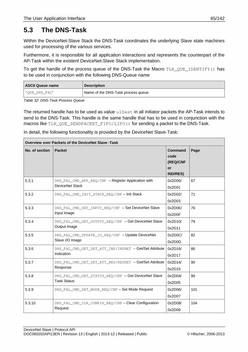
The User Application Interface 65/142
DeviceNet Slave | Protocol API DOC060202API13EN | Revision 13 | English | 2013-12 | Released | Public © Hilscher, 2006-2013
5.3 The DNS-Task
Within the DeviceNet-Slave Stack the DNS-Task coordinates the underlying Slave state machines used for processing of the various services.
Furthermore, it is responsible for all application interactions and represents the counterpart of the AP-Task within the existent DeviceNet-Slave Stack implementation.
To get the handle of the process queue of the DNS-Task the Macro TLR_QUE_IDENTIFY() has to be used in conjunction with the following DNS-Queue name
ASCII Queue name Description
"QUE_DNS_FAL” Name of the DNS-Task process queue
Table 32: DNS-Task Process Queue
The returned handle has to be used as value ulDest in all initiator packets the AP-Task intends to send to the DNS-Task. This handle is the same handle that has to be used in conjunction with the macros like TLR_QUE_SENDPACKET_FIFO/LIFO() for sending a packet to the DNS-Task.
In detail, the following functionality is provided by the DeviceNet Slave-Task:
Overview over Packets of the DeviceNet Slave -Task
No. of section Packet Command
code
(REQ/CNF
or
IND/RES)
Page
5.3.1 DNS_FAL_CMD_APP_REQ/CNF – Register Application with DeviceNet Stack
0x2D00/
0x2D01
67
5.3.2 DNS_FAL_CMD_INIT_STACK_REQ/CNF – Init Stack 0x2D02/
0x2D03
71
5.3.3 DNS_FAL_CMD_SET_INPUT_REQ/CNF – Set DeviceNet Slave Input Image
0x2D0E/
0x2D0F
76
5.3.4 DNS_FAL_CMD_GET_OUTPUT_REQ/CNF – Get DeviceNet Slave Output Image
0x2D10/
0x2D11
79
5.3.5 DNS_FAL_CMD_UPDATE_IO_REQ/CNF – Update DeviceNet Slave I/O Image
0x2D0C/
0x2D0D
82
5.3.6 DNS_FAL_CMD_GET_SET_ATT_IND/INDRET – Get/Set Attribute Indication
0x2D16/
0x2D17
86
5.3.7 DNS_FAL_CMD_GET_SET_ATT_RES/RESRET – Get/Set Attribute Response
0x2D14/
0x2D15
90
5.3.8 DNS_FAL_CMD_GET_STATUS_REQ/CNF – Get DeviceNet Slave Task Status
0x2D04/
0x2D05
96
5.3.9 DNS_FAL_CMD_SET_MODE_REQ/CNF – Set Mode Request 0x2D06/
0x2D07
101
5.3.10 DNS_FAL_CMD_CLR_CONFIG_REQ/CNF – Clear Configuration Request
0x2D08/
0x2D09
104
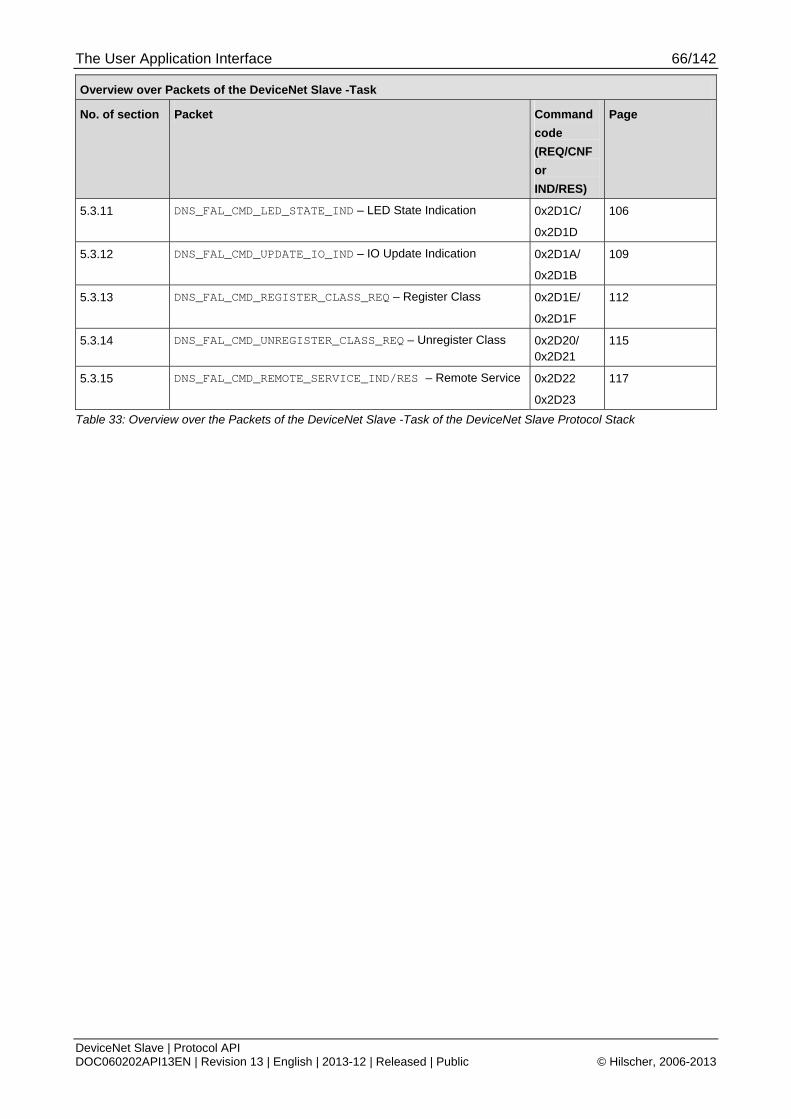
The User Application Interface 66/142
DeviceNet Slave | Protocol API DOC060202API13EN | Revision 13 | English | 2013-12 | Released | Public © Hilscher, 2006-2013
Overview over Packets of the DeviceNet Slave -Task
No. of section Packet Command
code
(REQ/CNF
or
IND/RES)
Page
5.3.11 DNS_FAL_CMD_LED_STATE_IND – LED State Indication 0x2D1C/
0x2D1D
106
5.3.12 DNS_FAL_CMD_UPDATE_IO_IND – IO Update Indication 0x2D1A/
0x2D1B
109
5.3.13 DNS_FAL_CMD_REGISTER_CLASS_REQ – Register Class 0x2D1E/
0x2D1F
112
5.3.14 DNS_FAL_CMD_UNREGISTER_CLASS_REQ – Unregister Class 0x2D20/ 0x2D21
115
5.3.15 DNS_FAL_CMD_REMOTE_SERVICE_IND/RES – Remote Service 0x2D22
0x2D23
117
Table 33: Overview over the Packets of the DeviceNet Slave -Task of the DeviceNet Slave Protocol Stack
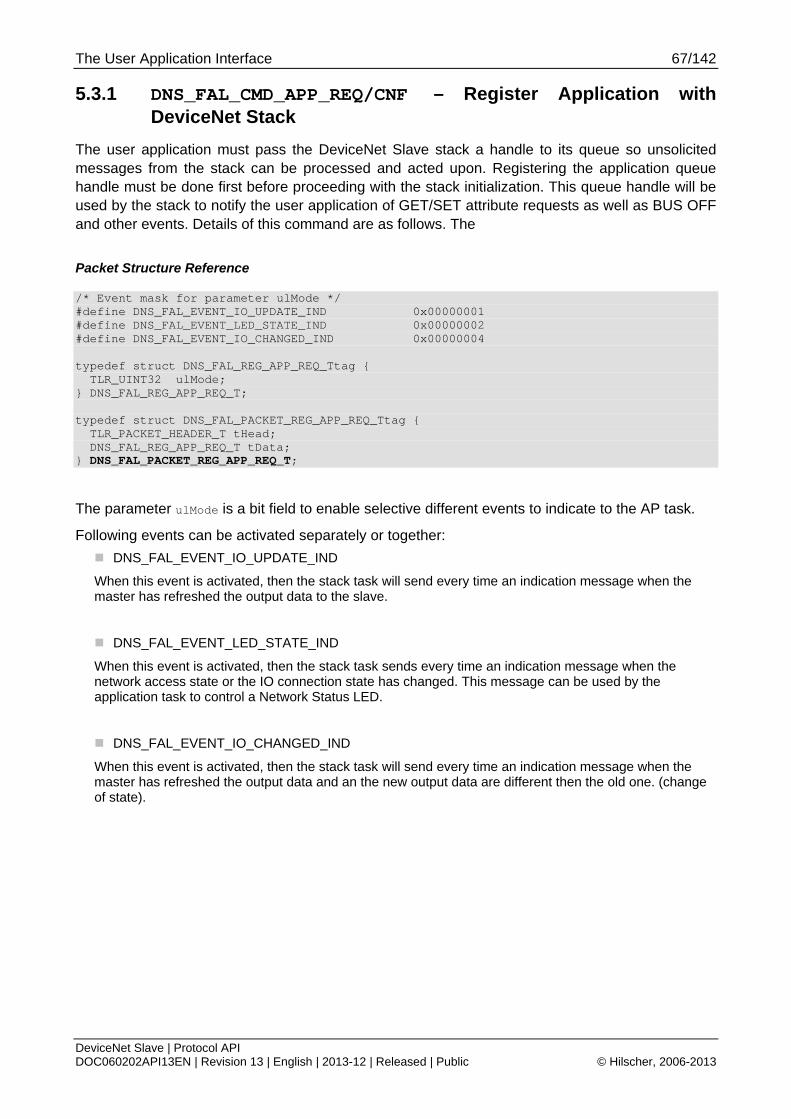
The User Application Interface 67/142
DeviceNet Slave | Protocol API DOC060202API13EN | Revision 13 | English | 2013-12 | Released | Public © Hilscher, 2006-2013
5.3.1 DNS_FAL_CMD_APP_REQ/CNF – Register Application with DeviceNet Stack
The user application must pass the DeviceNet Slave stack a handle to its queue so unsolicited messages from the stack can be processed and acted upon. Registering the application queue handle must be done first before proceeding with the stack initialization. This queue handle will be used by the stack to notify the user application of GET/SET attribute requests as well as BUS OFF and other events. Details of this command are as follows. The
Packet Structure Reference
/* Event mask for parameter ulMode */ #define DNS_FAL_EVENT_IO_UPDATE_IND 0x00000001 #define DNS_FAL_EVENT_LED_STATE_IND 0x00000002 #define DNS_FAL_EVENT_IO_CHANGED_IND 0x00000004 typedef struct DNS_FAL_REG_APP_REQ_Ttag { TLR_UINT32 ulMode; } DNS_FAL_REG_APP_REQ_T; typedef struct DNS_FAL_PACKET_REG_APP_REQ_Ttag { TLR_PACKET_HEADER_T tHead; DNS_FAL_REG_APP_REQ_T tData; } DNS_FAL_PACKET_REG_APP_REQ_T;
The parameter ulMode is a bit field to enable selective different events to indicate to the AP task.
Following events can be activated separately or together:
DNS_FAL_EVENT_IO_UPDATE_IND
When this event is activated, then the stack task will send every time an indication message when the master has refreshed the output data to the slave.
DNS_FAL_EVENT_LED_STATE_IND
When this event is activated, then the stack task sends every time an indication message when the network access state or the IO connection state has changed. This message can be used by the application task to control a Network Status LED.
DNS_FAL_EVENT_IO_CHANGED_IND
When this event is activated, then the stack task will send every time an indication message when the master has refreshed the output data and an the new output data are different then the old one. (change of state).

The User Application Interface 68/142
DeviceNet Slave | Protocol API DOC060202API13EN | Revision 13 | English | 2013-12 | Released | Public © Hilscher, 2006-2013
Packet Description
Structure DNS_FAL_PACKET_REG_APP_REQ_T Type: Request
Variable Type Value /
Range
Description
tHead - Structure TLR_PACKET_HEADER_T
ulDest UINT32 Destination Queue-Handle of DNS-Task Process Queue
ulSrc UINT32 Source Queue-Handle of AP-Task Process Queue
ulDestId UINT32 0 Destination End Point Identifier, specifying the final receiver of the packet within the Destination Process. Set to 0 for the Initialization Packet
ulSrcId UINT32 0 ... 232-1 Source End Point Identifier, specifying the origin of the packet inside the Source Process
ulLen UINT32 4 sizeof(DNS_FAL_REG_APP_REQ_T)
ulId UINT32 0 ... 232-1 Packet Identification as unique number generated by the Source Process of the Packet
ulSta UINT32 See Table 35: DNS_FAL_CMD_REG_APP_REQ – Packet Status/Error
ulCmd UINT32 0x2D00 DNS_FAL_CMD_REG_APP_REQ - Command
ulExt UINT32 0 Extension not in use, set to zero for compatibility reasons.
ulRout UINT32 0 Routing, do not touch
tData - Structure DNS_FAL_REG_APP_REQ_T
ulMode UINT32 0x000000010x000000020x00000004
Bitfield to enable selective different events to indicate to the AP task.DNS_FAL_EVENT_IO_UPDATE_IND DNS_FAL_EVENT_LED_STATE_IND DNS_FAL_EVENT_IO_CHANGED_IND
Table 34: DNS_FAL_CMD_REG_APP_REQ – Request Command for DNS Get Status
Packet Status/Error
Definition / (Value) Description
TLR_S_OK (0x00000000)
Status ok
Table 35: DNS_FAL_CMD_REG_APP_REQ – Packet Status/Error

The User Application Interface 69/142
DeviceNet Slave | Protocol API DOC060202API13EN | Revision 13 | English | 2013-12 | Released | Public © Hilscher, 2006-2013
Source Code Example
TLR_RESULT DnsApp_RegApp_Req(DNS_APP_RSC_T FAR* ptRsc, UINT32 ulMode ) { TLR_RESULT eRslt; DNS_FAL_PACKET_REG_APP_REQ_T *ptRegAppReq; eRslt = TLR_POOL_PACKET_GET(ptRsc->tLoc.hPool, &ptRegAppReq); if( eRslt == TLR_S_OK ) { TLR_QUE_LINK_SET_PACKET_SRC(ptRegAppReq,ptRsc->tLoc.tQueSrcDnsApp); ptRegAppReq->tHead.ulDst = ptRsc->tLoc.hDstQueDnsTsk; ptRegAppReq->tHead.ulDestId = 0; ptRegAppReq->tHead.ulCmd = DNS_FAL_CMD_REG_APP_REQ; ptRegAppReq->tHead.ulSta = 0; ptRegAppReq->tHead.ulExt = 0; ptRegAppReq->tHead.ulRout = 0; ptRegAppReq->tHead.ulLen = 4; /* Set the mode not used currently */ ptRegAppReq->tData.ulMode = 0; eRslt = TLR_QUE_SENDPACKET_FIFO(ptRsc->tLoc.tDnsFalQue,ptRegAppReq,TLR_FINITE); if( eRslt != TLR_S_OK ) { TLR_POOL_PACKET_RELEASE(ptRsc->tLoc.hPool, ptRegAppReq); } } return eRslt; }
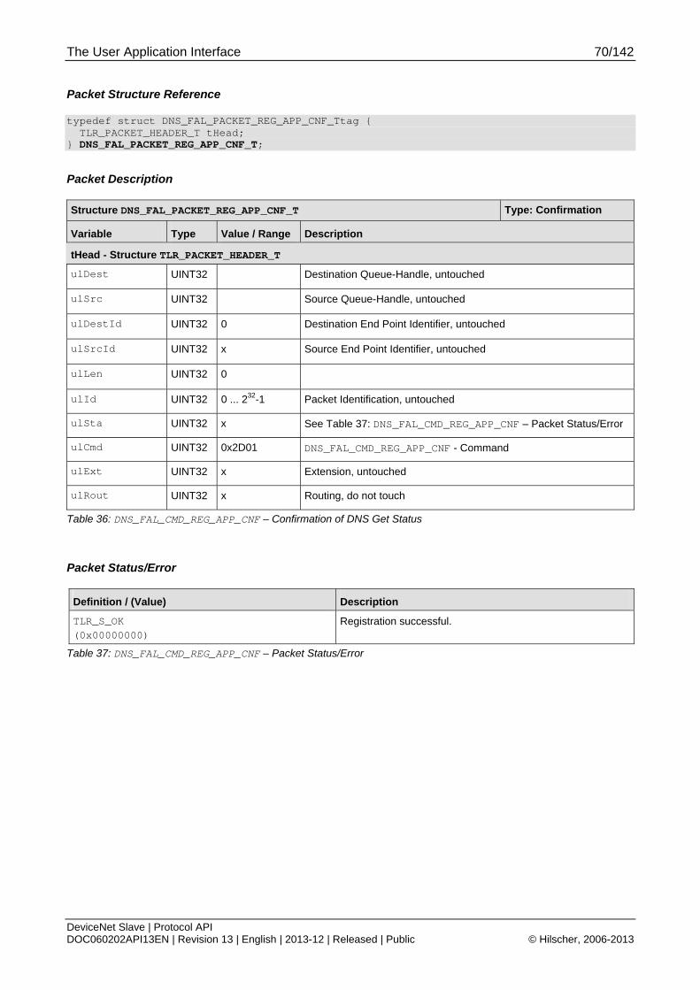
The User Application Interface 70/142
DeviceNet Slave | Protocol API DOC060202API13EN | Revision 13 | English | 2013-12 | Released | Public © Hilscher, 2006-2013
Packet Structure Reference
typedef struct DNS_FAL_PACKET_REG_APP_CNF_Ttag { TLR_PACKET_HEADER_T tHead; } DNS_FAL_PACKET_REG_APP_CNF_T;
Packet Description
Structure DNS_FAL_PACKET_REG_APP_CNF_T Type: Confirmation
Variable Type Value / Range Description
tHead - Structure TLR_PACKET_HEADER_T
ulDest UINT32 Destination Queue-Handle, untouched
ulSrc UINT32 Source Queue-Handle, untouched
ulDestId UINT32 0 Destination End Point Identifier, untouched
ulSrcId UINT32 x Source End Point Identifier, untouched
ulLen UINT32 0
ulId UINT32 0 ... 232-1 Packet Identification, untouched
ulSta UINT32 x See Table 37: DNS_FAL_CMD_REG_APP_CNF – Packet Status/Error
ulCmd UINT32 0x2D01 DNS_FAL_CMD_REG_APP_CNF - Command
ulExt UINT32 x Extension, untouched
ulRout UINT32 x Routing, do not touch
Table 36: DNS_FAL_CMD_REG_APP_CNF – Confirmation of DNS Get Status
Packet Status/Error
Definition / (Value) Description
TLR_S_OK (0x00000000)
Registration successful.
Table 37: DNS_FAL_CMD_REG_APP_CNF – Packet Status/Error
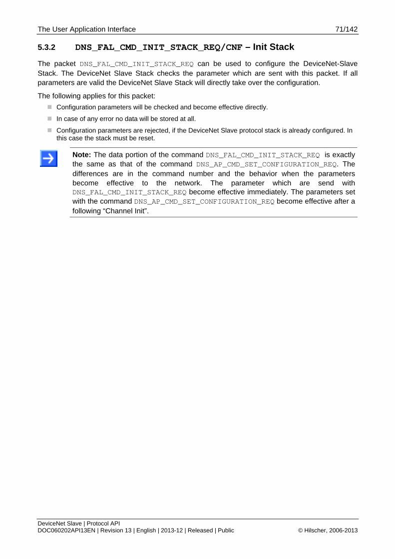
The User Application Interface 71/142
DeviceNet Slave | Protocol API DOC060202API13EN | Revision 13 | English | 2013-12 | Released | Public © Hilscher, 2006-2013
5.3.2 DNS_FAL_CMD_INIT_STACK_REQ/CNF – Init Stack
The packet DNS_FAL_CMD_INIT_STACK_REQ can be used to configure the DeviceNet-Slave Stack. The DeviceNet Slave Stack checks the parameter which are sent with this packet. If all parameters are valid the DeviceNet Slave Stack will directly take over the configuration.
The following applies for this packet:
Configuration parameters will be checked and become effective directly.
In case of any error no data will be stored at all.
Configuration parameters are rejected, if the DeviceNet Slave protocol stack is already configured. In this case the stack must be reset.
Note: The data portion of the command DNS_FAL_CMD_INIT_STACK_REQ is exactly the same as that of the command DNS_AP_CMD_SET_CONFIGURATION_REQ. The differences are in the command number and the behavior when the parameters become effective to the network. The parameter which are send with DNS_FAL_CMD_INIT_STACK_REQ become effective immediately. The parameters set with the command DNS_AP_CMD_SET_CONFIGURATION_REQ become effective after a following “Channel Init”.

The User Application Interface 72/142
DeviceNet Slave | Protocol API DOC060202API13EN | Revision 13 | English | 2013-12 | Released | Public © Hilscher, 2006-2013
Packet Structure Reference
/* System flags */ #define MSK_DNS_SYS_FLG_ADR_SW_ENABLE 0x00000010 #define MSK_DNS_SYS_FLG_BAUD_SW_ENABLE 0x00000020 #define MSK_DNS_SYS_FLG_RESERVED 0xFFFFFFCF /* DNS Baudrates */ #define DNS_FAL_BAUDRATE_500kB 0 #define DNS_FAL_BAUDRATE_250kB 1 #define DNS_FAL_BAUDRATE_125kB 2 /* Enable flags */ #define MSK_DNS_ENABLE_VENDORID 0x00000001 #define MSK_DNS_ENABLE_PRODUCTTYPE 0x00000002 #define MSK_DNS_ENABLE_PRODUCTCODE 0x00000004 #define MSK_DNS_ENABLE_MAJORMINORREV 0x00000008 #define MSK_DNS_ENABLE_SERIALNR 0x00000010 #define MSK_DNS_ENABLE_PRODUCTNAME 0x00000020 #define MSK_DNS_ENABLE_RESERVED 0xFFFFFFC0 /* Configuration flags */ #define MSK_DNS_CFG_FLAG_IGNORE_ADDR_SWITCH 0x00000001 #define MSK_DNS_CFG_FLAG_CONTINUE_ON_BUSOFF 0x00000002 #define MSK_DNS_CFG_FLAG_CONTINUE_ON_LOSS_NP 0x00000004 #define MSK_DNS_CFG_FLAG_RECVIDLE_CLEAR_DATA 0x00000008 #define MSK_DNS_CFG_FLAG_RECVIDLE_USER_DATA 0x00000010 #define MSK_DNS_CFG_FLAG_24VDCINVERT 0x00000020 #define MSK_DNS_CFG_FLAG_ENABLE_SET_PRODCONS_SIZE_REMOTE 0x00000040 #define MSK_DNS_CFG_FLAG_ENABLE_SET_MACID_REMOTE 0x00000080 #define MSK_DNS_CFG_FLAG_ENABLE_SET_BAUDRATE_REMOTE 0x00000100 #define MSK_DNS_CFG_FLAG_ENABLE_DATA_STATUS 0x00000200 #define MSK_DNS_CFG_FLAG_RESERVED 0xFFFFFC00 typedef struct DNS_FAL_INIT_STACK_REQ_Ttag { TLR_UINT32 ulSystemFlags; TLR_UINT32 ulWdgTime; TLR_UINT32 ulNodeId; TLR_UINT32 ulBaudrate; TLR_UINT32 ulProducedSize; TLR_UINT32 ulConsumedSize; TLR_UINT32 ulConfigFlags; TLR_UINT32 ulEnableFlags; TLR_UINT16 usVendorId; TLR_UINT16 usProductType; TLR_UINT16 usProductCode; TLR_UINT8 bMinorRev; TLR_UINT8 bMajorRev; TLR_UINT32 ulSerialNumber; TLR_UINT8 abReserved[3]; TLR_UINT8 bProductNameLen; TLR_UINT8 abProductName[32]; } DNS_FAL_INIT_STACK_REQ_T; typedef struct DNS_FAL_PACKET_INIT_STACK_REQ_Ttag { TLR_PACKET_HEADER_T tHead; DNS_FAL_INIT_STACK_REQ_T tData; } DNS_FAL_PACKET_INIT_STACK _REQ_T;
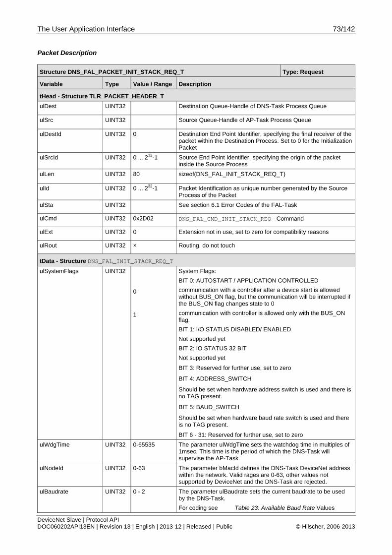
The User Application Interface 73/142
DeviceNet Slave | Protocol API DOC060202API13EN | Revision 13 | English | 2013-12 | Released | Public © Hilscher, 2006-2013
Packet Description
Structure DNS_FAL_PACKET_INIT_STACK_REQ_T Type: Request
Variable Type Value / Range Description
tHead - Structure TLR_PACKET_HEADER_T
ulDest UINT32 Destination Queue-Handle of DNS-Task Process Queue
ulSrc UINT32 Source Queue-Handle of AP-Task Process Queue
ulDestId UINT32 0 Destination End Point Identifier, specifying the final receiver of the packet within the Destination Process. Set to 0 for the Initialization Packet
ulSrcId UINT32 0 ... 232-1 Source End Point Identifier, specifying the origin of the packet inside the Source Process
ulLen UINT32 80 sizeof(DNS_FAL_INIT_STACK_REQ_T)
ulId UINT32 0 ... 232-1 Packet Identification as unique number generated by the Source Process of the Packet
ulSta UINT32 See section 6.1 Error Codes of the FAL-Task
ulCmd UINT32 0x2D02 DNS_FAL_CMD_INIT_STACK_REQ - Command
ulExt UINT32 0 Extension not in use, set to zero for compatibility reasons
ulRout UINT32 × Routing, do not touch
tData - Structure DNS_FAL_INIT_STACK_REQ_T
ulSystemFlags UINT32 0
1
System Flags:
BIT 0: AUTOSTART / APPLICATION CONTROLLED
communication with a controller after a device start is allowed without BUS_ON flag, but the communication will be interrupted if the BUS_ON flag changes state to 0
communication with controller is allowed only with the BUS_ON flag.
BIT 1: I/O STATUS DISABLED/ ENABLED
Not supported yet
BIT 2: IO STATUS 32 BIT
Not supported yet
BIT 3: Reserved for further use, set to zero
BIT 4: ADDRESS_SWITCH
Should be set when hardware address switch is used and there is no TAG present.
BIT 5: BAUD_SWITCH
Should be set when hardware baud rate switch is used and there is no TAG present.
BIT 6 - 31: Reserved for further use, set to zero
ulWdgTime UINT32 0-65535 The parameter ulWdgTime sets the watchdog time in multiples of 1msec. This time is the period of which the DNS-Task will supervise the AP-Task.
ulNodeId UINT32 0-63 The parameter bMacId defines the DNS-Task DeviceNet address within the network. Valid rages are 0-63, other values not supported by DeviceNet and the DNS-Task are rejected.
ulBaudrate UINT32 0 - 2 The parameter ulBaudrate sets the current baudrate to be used by the DNS-Task.
For coding see Table 23: Available Baud Rate Values

The User Application Interface 74/142
DeviceNet Slave | Protocol API DOC060202API13EN | Revision 13 | English | 2013-12 | Released | Public © Hilscher, 2006-2013
Structure DNS_FAL_PACKET_INIT_STACK_REQ_T Type: Request
Variable Type Value / Range Description
ulProducedSize UINT32 0-255 ulProducedSize sets the number of input bytes the DNS-Task shall produce in the view of a master for each established connection.
ulConsumedSize UINT32 0-255 ulConsumedSize sets the number of output bytes the DNS-Task shall consume in the view of a master for each established connection.
ulConfigFlags UINT32 0-31
The variable ulConfigFlags defines configuration parameters.
For coding see Table 24: Meaning of ConfigFlags Byte
ulEnableFlags UINT32 The variable ulEnableFlags indicates to the DNS-Task if the following identity variables usProductType, usProductCode, bMinorRev, bMajorRev and the ProdName are filled with user application specific data. For coding see Table 25: Meaning of EnableFlags Byte
0 denotes: Use settings from stack
usVendorId UINT16 283
(Changeable)
The parameter usVendorId is a DeviceNet specific unique number which is fixed by the ODVA for each DeviceNet manufacturer. The DNS-Task itself uses this ID during the Duplicate MAC-ID check phase and within each sent Duplicate MAC-Id check response. The value range of this variable is not limited. The Hilscher ID is 283dec.
usProductType UINT16 12 The variable usProductType is the indication of the general type of product. The Hilscher standard value for this is 12 which is a Communications Adapter.
usProductCode UINT16 The variable usProductCode is the identification of a particular product within a defined device type.
bMinorRev UINT8 1-255 The variable bMinorRev is one part of the revision which identifies the revision of the DNS device. The revision attribute consists of Major and Minor Revisions and they are typically displayed as major.minor.
bMajorRev UINT8 1-255 The variable bMajorRev is the second part of the revision. The Major Revision attribute is limited to 7 bits. The eighth bit is reserved by DeviceNet and must have a default value of zero.
ulSerialnumber UINT32 The ulSerialnumber is the eight byte serial number of the user created device.
abReserved[3] UINT8 Reserved
bProductNameLen UINT8 1-32 The variable bProdNameLen is the length of abProdName. The maximum number of characters in this string is 32.
abProductName[32] UINT8[] The variable abProdName is a text string that should represent a short description of the product/product family. The maximum number of characters in this string is 32. The number of characters must be set in the variable bProdNameLen.
Table 38: DNS_FAL_CMD_INIT_STACK_REQ – Request Command for DNS Stack Initialization
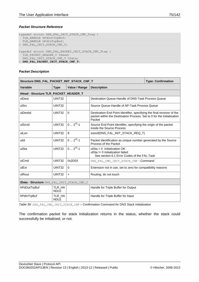
The User Application Interface 75/142
DeviceNet Slave | Protocol API DOC060202API13EN | Revision 13 | English | 2013-12 | Released | Public © Hilscher, 2006-2013
Packet Structure Reference
typedef struct DNS_FAL_INIT_STACK_CNF_Ttag { TLR_HANDLE hPdOutTrpBuf; TLR_HANDLE hPdInTrpBuf; } DNS_FAL_INIT_STACK_CNF_T; typedef struct DNS_FAL_PACKET_INIT_STACK_CNF_Ttag { TLR_PACKET_HEADER_T tHead; DNS_FAL_INIT_STACK_CNF_T tData; } DNS_FAL_PACKET_INIT_STACK_CNF_T;
Packet Description
Structure DNS_FAL_PACKET_INIT_STACK_CNF_T Type: Confirmation
Variable Type Value / Range Description
tHead - Structure TLR_PACKET_HEADER_T
ulDest UINT32 Destination Queue-Handle of DNS-Task Process Queue
ulSrc UINT32 Source Queue-Handle of AP-Task Process Queue
ulDestId UINT32 0 Destination End Point Identifier, specifying the final receiver of the packet within the Destination Process. Set to 0 for the Initialization Packet
ulSrcId UINT32 0 ... 232-1 Source End Point Identifier, specifying the origin of the packet inside the Source Process
ulLen UINT32 8 sizeof(DNS_FAL_INIT_STACK_REQ_T)
ulId UINT32 0 ... 232-1 Packet Identification as unique number generated by the Source Process of the Packet
ulSta UINT32 0 ... 232-1 ulSta = 0 Initialization OK ulSta != 0 Initialization failed See section 6.1 Error Codes of the FAL-Task
ulCmd UINT32 0x2D03 DNS_FAL_CMD_INIT_STACK_CNF - Command
ulExt UINT32 0 Extension not in use, set to zero for compatibility reasons
ulRout UINT32 × Routing, do not touch
tData - Structure DNS_FAL_INIT_STACK_CNF_T
hPdOutTrpBuf TLR_HANDLE
Handle for Triple Buffer for Output
hPdInTrpBuf TLR_HANDLE
Handle for Triple Buffer for Input
Table 39: DNS_FAL_CMD_INIT_STACK_CNF – Confirmation Command for DNS Stack Initialization
The confirmation packet for stack Initialization returns in the status, whether the stack could successfully be initialized, or not.
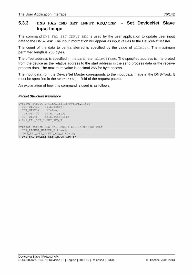
The User Application Interface 76/142
DeviceNet Slave | Protocol API DOC060202API13EN | Revision 13 | English | 2013-12 | Released | Public © Hilscher, 2006-2013
5.3.3 DNS_FAL_CMD_SET_INPUT_REQ/CNF – Set DeviceNet Slave Input Image
The command DNS_FAL_SET_INPUT_REQ is used by the user application to update user input data to the DNS-Task. The input information will appear as input values to the DeviceNet Master.
The count of the data to be transferred is specified by the value of ulInLen. The maximum permitted length is 255 bytes.
The offset address is specified in the parameter ulInOffSet. The specified address is interpreted from the device as the relative address to the start address in the send process data or the receive process data. The maximum value is decimal 255 for byte access.
The input data from the DeviceNet Master corresponds to the input data image in the DNS-Task. It must be specified in the abInData[] field of the request packet.
An explanation of how this command is used is as follows.
Packet Structure Reference
typedef struct DNS_FAL_SET_INPUT_REQ_Ttag { TLR_UINT32 ulInOffSet; TLR_UINT32 ulInLen; TLR_UINT32 ulInDataSta; TLR_UINT8 abInData[256]; } DNS_FAL_SET_INPUT_REQ_T; typedef struct DNS_FAL_PACKET_SET_INPUT_REQ_Ttag { TLR_PACKET_HEADER_T tHead;
DNS_FAL_SET_INPUT_REQ_T tData; } DNS_FAL_PACKET_SET_INPUT_REQ_T;
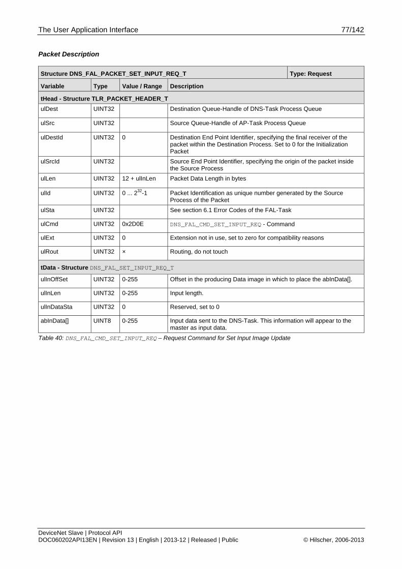
The User Application Interface 77/142
DeviceNet Slave | Protocol API DOC060202API13EN | Revision 13 | English | 2013-12 | Released | Public © Hilscher, 2006-2013
Packet Description
Structure DNS_FAL_PACKET_SET_INPUT_REQ_T Type: Request
Variable Type Value / Range Description
tHead - Structure TLR_PACKET_HEADER_T
ulDest UINT32 Destination Queue-Handle of DNS-Task Process Queue
ulSrc UINT32 Source Queue-Handle of AP-Task Process Queue
ulDestId UINT32 0 Destination End Point Identifier, specifying the final receiver of the packet within the Destination Process. Set to 0 for the Initialization Packet
ulSrcId UINT32 Source End Point Identifier, specifying the origin of the packet inside the Source Process
ulLen UINT32 12 + ulInLen Packet Data Length in bytes
ulId UINT32 0 ... 232-1 Packet Identification as unique number generated by the Source Process of the Packet
ulSta UINT32 See section 6.1 Error Codes of the FAL-Task
ulCmd UINT32 0x2D0E DNS_FAL_CMD_SET_INPUT_REQ - Command
ulExt UINT32 0 Extension not in use, set to zero for compatibility reasons
ulRout UINT32 × Routing, do not touch
tData - Structure DNS_FAL_SET_INPUT_REQ_T
ulInOffSet UINT32 0-255 Offset in the producing Data image in which to place the abInData[].
ulInLen UINT32 0-255 Input length.
ulInDataSta UINT32 0 Reserved, set to 0
abInData[] UINT8 0-255 Input data sent to the DNS-Task. This information will appear to the master as input data.
Table 40: DNS_FAL_CMD_SET_INPUT_REQ – Request Command for Set Input Image Update
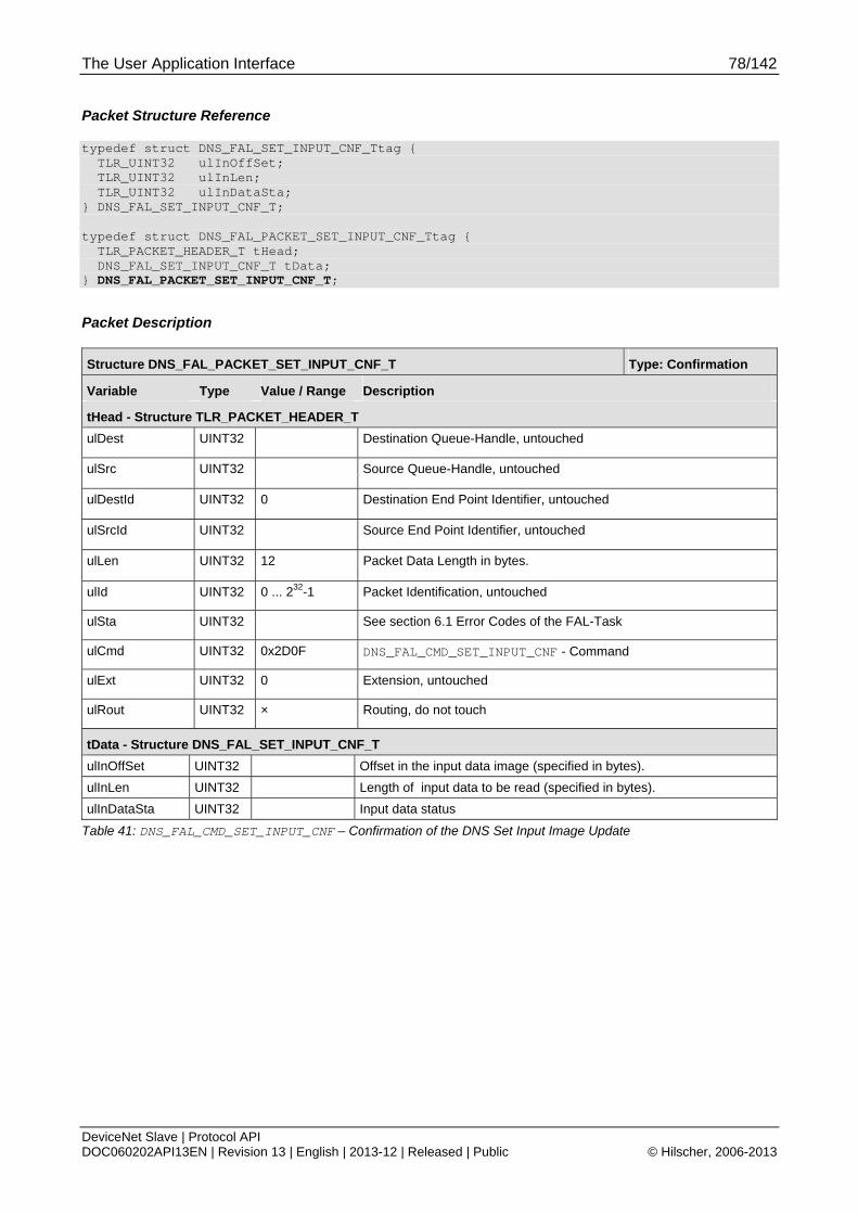
The User Application Interface 78/142
DeviceNet Slave | Protocol API DOC060202API13EN | Revision 13 | English | 2013-12 | Released | Public © Hilscher, 2006-2013
Packet Structure Reference
typedef struct DNS_FAL_SET_INPUT_CNF_Ttag { TLR_UINT32 ulInOffSet; TLR_UINT32 ulInLen; TLR_UINT32 ulInDataSta; } DNS_FAL_SET_INPUT_CNF_T; typedef struct DNS_FAL_PACKET_SET_INPUT_CNF_Ttag { TLR_PACKET_HEADER_T tHead; DNS_FAL_SET_INPUT_CNF_T tData; } DNS_FAL_PACKET_SET_INPUT_CNF_T;
Packet Description
Structure DNS_FAL_PACKET_SET_INPUT_CNF_T Type: Confirmation
Variable Type Value / Range Description
tHead - Structure TLR_PACKET_HEADER_T
ulDest UINT32 Destination Queue-Handle, untouched
ulSrc UINT32 Source Queue-Handle, untouched
ulDestId UINT32 0 Destination End Point Identifier, untouched
ulSrcId UINT32 Source End Point Identifier, untouched
ulLen UINT32 12 Packet Data Length in bytes.
ulId UINT32 0 ... 232-1 Packet Identification, untouched
ulSta UINT32 See section 6.1 Error Codes of the FAL-Task
ulCmd UINT32 0x2D0F DNS_FAL_CMD_SET_INPUT_CNF - Command
ulExt UINT32 0 Extension, untouched
ulRout UINT32 × Routing, do not touch
tData - Structure DNS_FAL_SET_INPUT_CNF_T
ulInOffSet UINT32 Offset in the input data image (specified in bytes).
ulInLen UINT32 Length of input data to be read (specified in bytes).
ulInDataSta UINT32 Input data status
Table 41: DNS_FAL_CMD_SET_INPUT_CNF – Confirmation of the DNS Set Input Image Update
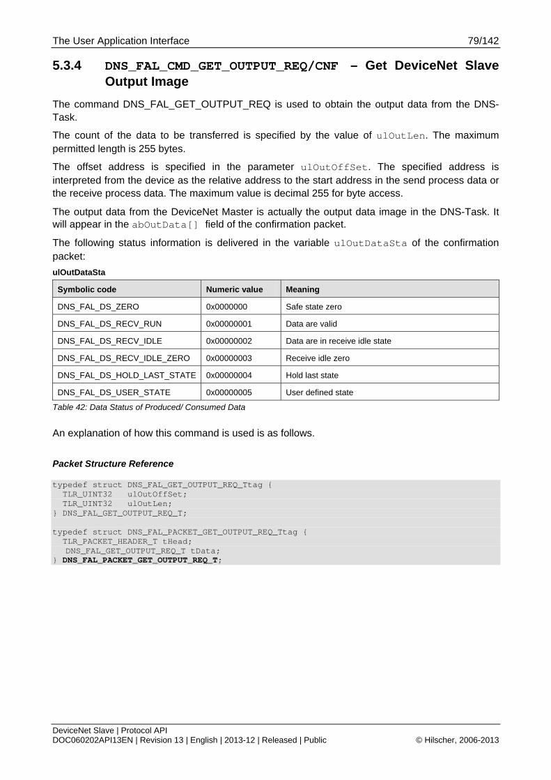
The User Application Interface 79/142
DeviceNet Slave | Protocol API DOC060202API13EN | Revision 13 | English | 2013-12 | Released | Public © Hilscher, 2006-2013
5.3.4 DNS_FAL_CMD_GET_OUTPUT_REQ/CNF – Get DeviceNet Slave Output Image
The command DNS_FAL_GET_OUTPUT_REQ is used to obtain the output data from the DNS-Task.
The count of the data to be transferred is specified by the value of ulOutLen. The maximum permitted length is 255 bytes.
The offset address is specified in the parameter ulOutOffSet. The specified address is interpreted from the device as the relative address to the start address in the send process data or the receive process data. The maximum value is decimal 255 for byte access.
The output data from the DeviceNet Master is actually the output data image in the DNS-Task. It will appear in the abOutData[] field of the confirmation packet.
The following status information is delivered in the variable ulOutDataSta of the confirmation packet:
ulOutDataSta
Symbolic code Numeric value Meaning
DNS_FAL_DS_ZERO 0x0000000 Safe state zero
DNS_FAL_DS_RECV_RUN 0x00000001 Data are valid
DNS_FAL_DS_RECV_IDLE 0x00000002 Data are in receive idle state
DNS_FAL_DS_RECV_IDLE_ZERO 0x00000003 Receive idle zero
DNS_FAL_DS_HOLD_LAST_STATE 0x00000004 Hold last state
DNS_FAL_DS_USER_STATE 0x00000005 User defined state
Table 42: Data Status of Produced/ Consumed Data
An explanation of how this command is used is as follows.
Packet Structure Reference
typedef struct DNS_FAL_GET_OUTPUT_REQ_Ttag { TLR_UINT32 ulOutOffSet; TLR_UINT32 ulOutLen; } DNS_FAL_GET_OUTPUT_REQ_T; typedef struct DNS_FAL_PACKET_GET_OUTPUT_REQ_Ttag { TLR_PACKET_HEADER_T tHead;
DNS_FAL_GET_OUTPUT_REQ_T tData; } DNS_FAL_PACKET_GET_OUTPUT_REQ_T;
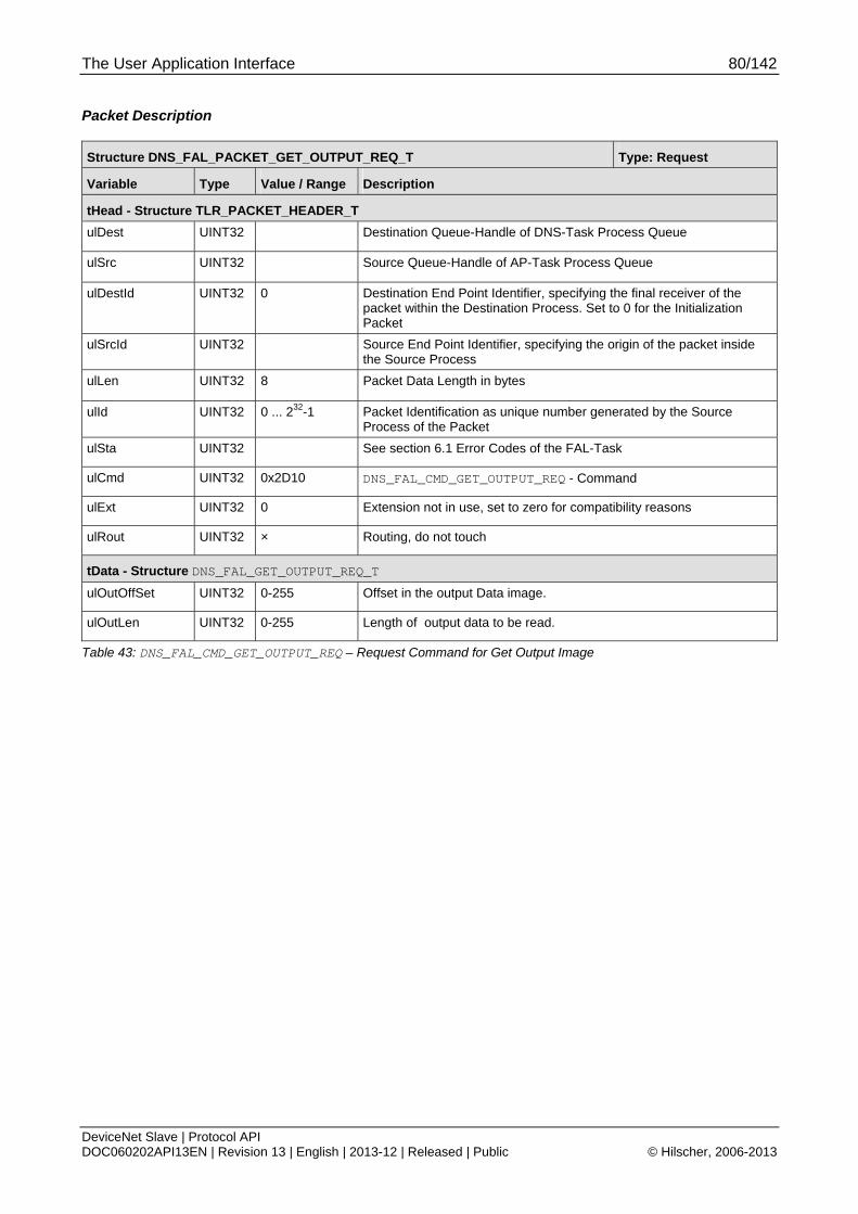
The User Application Interface 80/142
DeviceNet Slave | Protocol API DOC060202API13EN | Revision 13 | English | 2013-12 | Released | Public © Hilscher, 2006-2013
Packet Description
Structure DNS_FAL_PACKET_GET_OUTPUT_REQ_T Type: Request
Variable Type Value / Range Description
tHead - Structure TLR_PACKET_HEADER_T
ulDest UINT32 Destination Queue-Handle of DNS-Task Process Queue
ulSrc UINT32 Source Queue-Handle of AP-Task Process Queue
ulDestId UINT32 0 Destination End Point Identifier, specifying the final receiver of the packet within the Destination Process. Set to 0 for the Initialization Packet
ulSrcId UINT32 Source End Point Identifier, specifying the origin of the packet inside the Source Process
ulLen UINT32 8 Packet Data Length in bytes
ulId UINT32 0 ... 232-1 Packet Identification as unique number generated by the Source Process of the Packet
ulSta UINT32 See section 6.1 Error Codes of the FAL-Task
ulCmd UINT32 0x2D10 DNS_FAL_CMD_GET_OUTPUT_REQ - Command
ulExt UINT32 0 Extension not in use, set to zero for compatibility reasons
ulRout UINT32 × Routing, do not touch
tData - Structure DNS_FAL_GET_OUTPUT_REQ_T
ulOutOffSet UINT32 0-255 Offset in the output Data image.
ulOutLen UINT32 0-255 Length of output data to be read.
Table 43: DNS_FAL_CMD_GET_OUTPUT_REQ – Request Command for Get Output Image
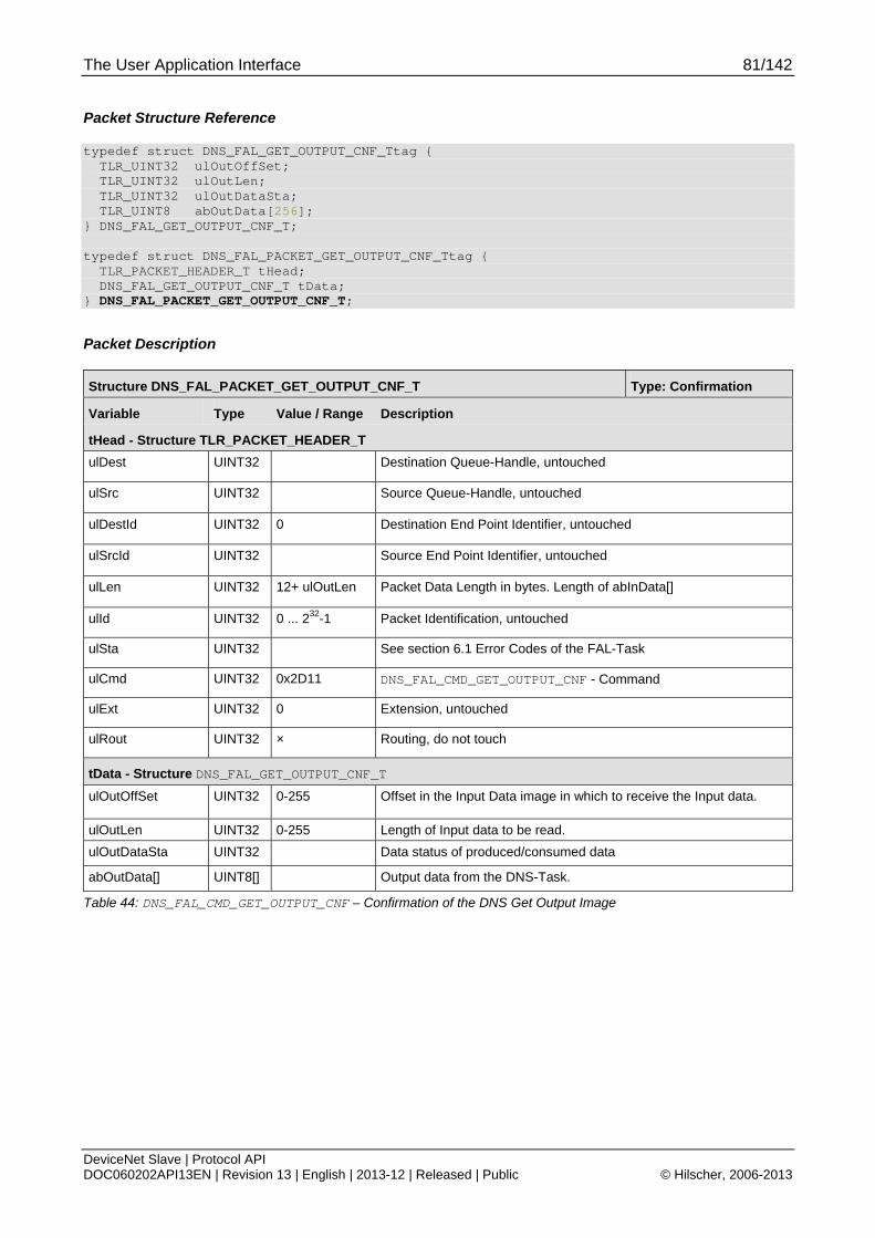
The User Application Interface 81/142
DeviceNet Slave | Protocol API DOC060202API13EN | Revision 13 | English | 2013-12 | Released | Public © Hilscher, 2006-2013
Packet Structure Reference
typedef struct DNS_FAL_GET_OUTPUT_CNF_Ttag { TLR_UINT32 ulOutOffSet; TLR_UINT32 ulOutLen; TLR_UINT32 ulOutDataSta; TLR_UINT8 abOutData[256]; } DNS_FAL_GET_OUTPUT_CNF_T; typedef struct DNS_FAL_PACKET_GET_OUTPUT_CNF_Ttag { TLR_PACKET_HEADER_T tHead; DNS_FAL_GET_OUTPUT_CNF_T tData; } DNS_FAL_PACKET_GET_OUTPUT_CNF_T;
Packet Description
Structure DNS_FAL_PACKET_GET_OUTPUT_CNF_T Type: Confirmation
Variable Type Value / Range Description
tHead - Structure TLR_PACKET_HEADER_T
ulDest UINT32 Destination Queue-Handle, untouched
ulSrc UINT32 Source Queue-Handle, untouched
ulDestId UINT32 0 Destination End Point Identifier, untouched
ulSrcId UINT32 Source End Point Identifier, untouched
ulLen UINT32 12+ ulOutLen Packet Data Length in bytes. Length of abInData[]
ulId UINT32 0 ... 232-1 Packet Identification, untouched
ulSta UINT32 See section 6.1 Error Codes of the FAL-Task
ulCmd UINT32 0x2D11 DNS_FAL_CMD_GET_OUTPUT_CNF - Command
ulExt UINT32 0 Extension, untouched
ulRout UINT32 × Routing, do not touch
tData - Structure DNS_FAL_GET_OUTPUT_CNF_T
ulOutOffSet UINT32 0-255 Offset in the Input Data image in which to receive the Input data.
ulOutLen UINT32 0-255 Length of Input data to be read.
ulOutDataSta UINT32 Data status of produced/consumed data
abOutData[] UINT8[] Output data from the DNS-Task.
Table 44: DNS_FAL_CMD_GET_OUTPUT_CNF – Confirmation of the DNS Get Output Image
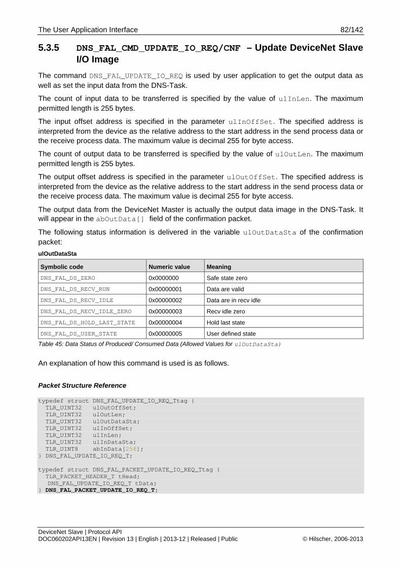
The User Application Interface 82/142
DeviceNet Slave | Protocol API DOC060202API13EN | Revision 13 | English | 2013-12 | Released | Public © Hilscher, 2006-2013
5.3.5 DNS_FAL_CMD_UPDATE_IO_REQ/CNF – Update DeviceNet Slave I/O Image
The command DNS_FAL_UPDATE_IO_REQ is used by user application to get the output data as well as set the input data from the DNS-Task.
The count of input data to be transferred is specified by the value of ulInLen. The maximum permitted length is 255 bytes.
The input offset address is specified in the parameter ulInOffSet. The specified address is interpreted from the device as the relative address to the start address in the send process data or the receive process data. The maximum value is decimal 255 for byte access.
The count of output data to be transferred is specified by the value of ulOutLen. The maximum permitted length is 255 bytes.
The output offset address is specified in the parameter ulOutOffSet. The specified address is interpreted from the device as the relative address to the start address in the send process data or the receive process data. The maximum value is decimal 255 for byte access.
The output data from the DeviceNet Master is actually the output data image in the DNS-Task. It will appear in the abOutData[] field of the confirmation packet.
The following status information is delivered in the variable ulOutDataSta of the confirmation packet:
ulOutDataSta
Symbolic code Numeric value Meaning
DNS_FAL_DS_ZERO 0x0000000 Safe state zero
DNS_FAL_DS_RECV_RUN 0x00000001 Data are valid
DNS_FAL_DS_RECV_IDLE 0x00000002 Data are in recv idle
DNS_FAL_DS_RECV_IDLE_ZERO 0x00000003 Recv idle zero
DNS_FAL_DS_HOLD_LAST_STATE 0x00000004 Hold last state
DNS_FAL_DS_USER_STATE 0x00000005 User defined state
Table 45: Data Status of Produced/ Consumed Data (Allowed Values for ulOutDataSta)
An explanation of how this command is used is as follows.
Packet Structure Reference
typedef struct DNS_FAL_UPDATE_IO_REQ_Ttag { TLR_UINT32 ulOutOffSet; TLR_UINT32 ulOutLen; TLR_UINT32 ulOutDataSta; TLR_UINT32 ulInOffSet; TLR_UINT32 ulInLen; TLR_UINT32 ulInDataSta; TLR_UINT8 abInData[256]; } DNS_FAL_UPDATE_IO_REQ_T; typedef struct DNS_FAL_PACKET_UPDATE_IO_REQ_Ttag { TLR_PACKET_HEADER_T tHead;
DNS_FAL_UPDATE_IO_REQ_T tData; } DNS_FAL_PACKET_UPDATE_IO_REQ_T;
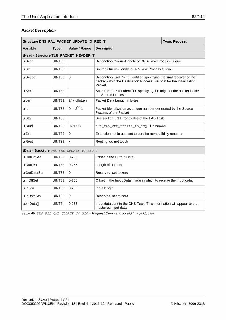
The User Application Interface 83/142
DeviceNet Slave | Protocol API DOC060202API13EN | Revision 13 | English | 2013-12 | Released | Public © Hilscher, 2006-2013
Packet Description
Structure DNS_FAL_PACKET_UPDATE_IO_REQ_T Type: Request
Variable Type Value / Range Description
tHead - Structure TLR_PACKET_HEADER_T
ulDest UINT32 Destination Queue-Handle of DNS-Task Process Queue
ulSrc UINT32 Source Queue-Handle of AP-Task Process Queue
ulDestId UINT32 0 Destination End Point Identifier, specifying the final receiver of the packet within the Destination Process. Set to 0 for the Initialization Packet
ulSrcId UINT32 Source End Point Identifier, specifying the origin of the packet inside the Source Process
ulLen UINT32 24+ ulInLen Packet Data Length in bytes
ulId UINT32 0 ... 232-1 Packet Identification as unique number generated by the Source Process of the Packet
ulSta UINT32 See section 6.1 Error Codes of the FAL-Task
ulCmd UINT32 0x2D0C DNS_FAL_CMD_UPDATE_IO_REQ - Command
ulExt UINT32 0 Extension not in use, set to zero for compatibility reasons
ulRout UINT32 × Routing, do not touch
tData - Structure DNS_FAL_UPDATE_IO_REQ_T
ulOutOffSet UINT32 0-255 Offset in the Output Data.
ulOutLen UINT32 0-255 Length of outputs.
ulOutDataSta UINT32 0 Reserved, set to zero
ulInOffSet UINT32 0-255 Offset in the Input Data image in which to receive the Input data.
ulInLen UINT32 0-255 Input length.
ulInDataSta UINT32 0 Reserved, set to zero
abInData[] UINT8 0-255 Input data sent to the DNS-Task. This information will appear to the master as input data.
Table 46: DNS_FAL_CMD_UPDATE_IO_REQ – Request Command for I/O Image Update
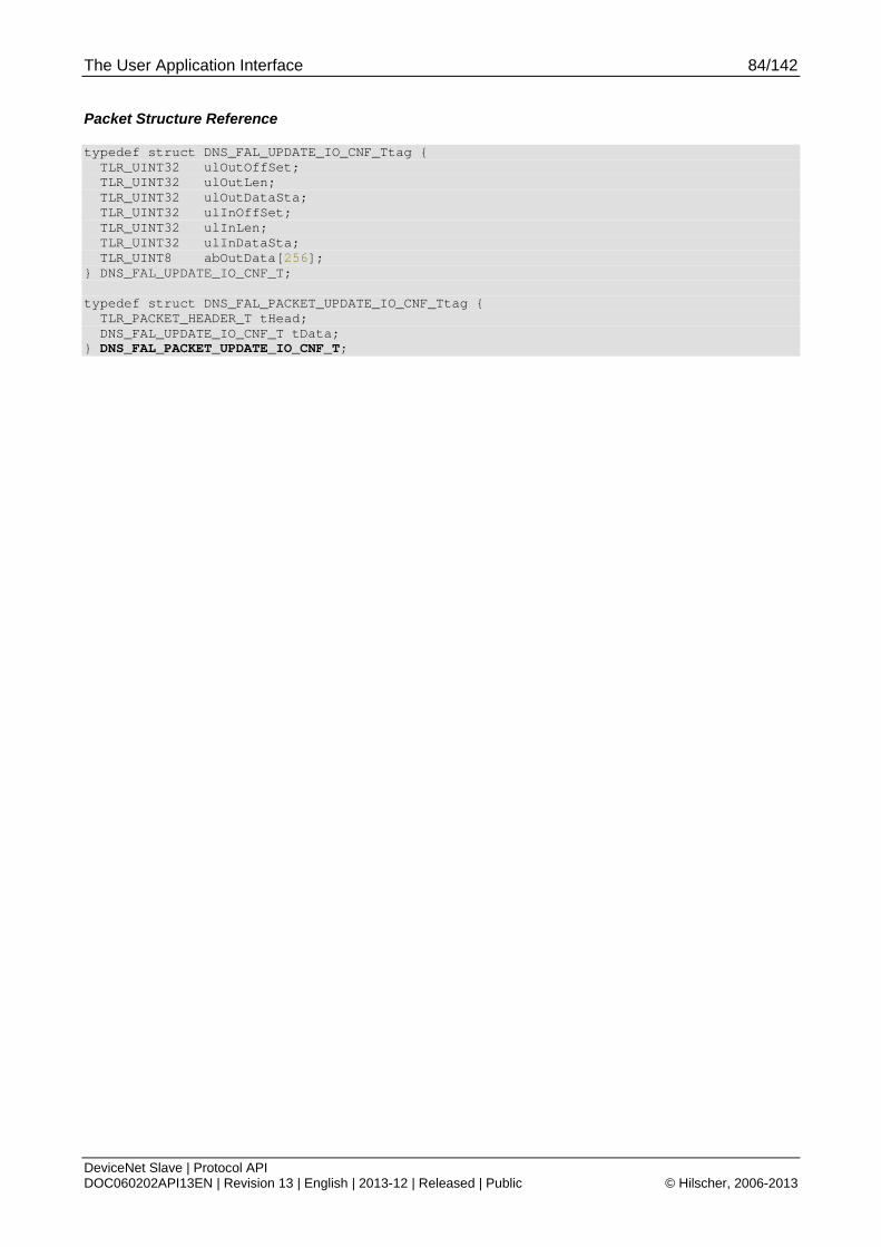
The User Application Interface 84/142
DeviceNet Slave | Protocol API DOC060202API13EN | Revision 13 | English | 2013-12 | Released | Public © Hilscher, 2006-2013
Packet Structure Reference
typedef struct DNS_FAL_UPDATE_IO_CNF_Ttag { TLR_UINT32 ulOutOffSet; TLR_UINT32 ulOutLen; TLR_UINT32 ulOutDataSta; TLR_UINT32 ulInOffSet; TLR_UINT32 ulInLen; TLR_UINT32 ulInDataSta; TLR_UINT8 abOutData[256]; } DNS_FAL_UPDATE_IO_CNF_T; typedef struct DNS_FAL_PACKET_UPDATE_IO_CNF_Ttag { TLR_PACKET_HEADER_T tHead; DNS_FAL_UPDATE_IO_CNF_T tData; } DNS_FAL_PACKET_UPDATE_IO_CNF_T;
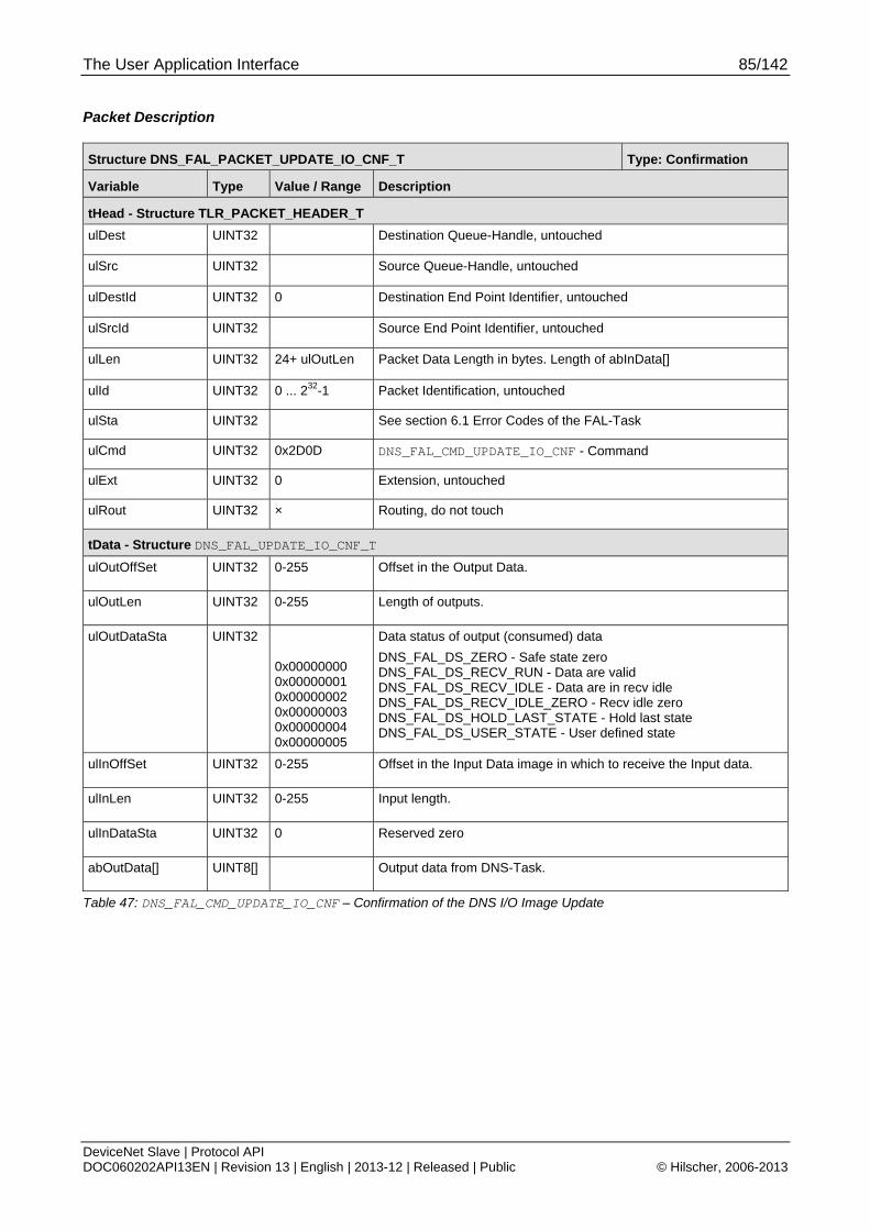
The User Application Interface 85/142
DeviceNet Slave | Protocol API DOC060202API13EN | Revision 13 | English | 2013-12 | Released | Public © Hilscher, 2006-2013
Packet Description
Structure DNS_FAL_PACKET_UPDATE_IO_CNF_T Type: Confirmation
Variable Type Value / Range Description
tHead - Structure TLR_PACKET_HEADER_T
ulDest UINT32 Destination Queue-Handle, untouched
ulSrc UINT32 Source Queue-Handle, untouched
ulDestId UINT32 0 Destination End Point Identifier, untouched
ulSrcId UINT32 Source End Point Identifier, untouched
ulLen UINT32 24+ ulOutLen Packet Data Length in bytes. Length of abInData[]
ulId UINT32 0 ... 232-1 Packet Identification, untouched
ulSta UINT32 See section 6.1 Error Codes of the FAL-Task
ulCmd UINT32 0x2D0D DNS_FAL_CMD_UPDATE_IO_CNF - Command
ulExt UINT32 0 Extension, untouched
ulRout UINT32 × Routing, do not touch
tData - Structure DNS_FAL_UPDATE_IO_CNF_T
ulOutOffSet UINT32 0-255 Offset in the Output Data.
ulOutLen UINT32 0-255 Length of outputs.
ulOutDataSta UINT32 0x00000000 0x00000001 0x00000002 0x00000003 0x00000004 0x00000005
Data status of output (consumed) data
DNS_FAL_DS_ZERO - Safe state zero DNS_FAL_DS_RECV_RUN - Data are valid DNS_FAL_DS_RECV_IDLE - Data are in recv idle DNS_FAL_DS_RECV_IDLE_ZERO - Recv idle zero DNS_FAL_DS_HOLD_LAST_STATE - Hold last state DNS_FAL_DS_USER_STATE - User defined state
ulInOffSet UINT32 0-255 Offset in the Input Data image in which to receive the Input data.
ulInLen UINT32 0-255 Input length.
ulInDataSta UINT32 0 Reserved zero
abOutData[] UINT8[] Output data from DNS-Task.
Table 47: DNS_FAL_CMD_UPDATE_IO_CNF – Confirmation of the DNS I/O Image Update
The User Application Interface 86/142
DeviceNet Slave | Protocol API DOC060202API13EN | Revision 13 | English | 2013-12 | Released | Public © Hilscher, 2006-2013
5.3.6 DNS_FAL_CMD_GET_SET_ATT_IND/INDRET – Get/Set Attribute Indication
If the explicit message channel between master and device has been established correctly, the user application may receive unsolicited indications from the DeviceNet-Task as a defined range of accessible Class-IDs are routed by the device through the mailboxes, if they are accessed.
The Get/Set Attribute Indication command signals the user application that a Get/Set attribute request was sent by a DeviceNet Master. The user is expected to provide a response to this command to acknowledge its receipt including return data. Otherwise, the user is endangered to be excluded from communication on the DeviceNet as usually Get- and Set Attribute commands are supervised by the master via a timer.
Note: To receive this command to the user application the command DNS_FAL_CMD_REGISTER_CLASS must be used to allow the stack to forward this indication to user for each class.
Furthermore, RCX_REGISTER_APP_REQ is required to be able to receive indications. The device can only be an Explicite Message Server, that means requested Get- and Set Attribute commands of the master device can only be answered passively. An active initiate of Get- and Set Attribute commands by the device cannot be performed.
After registering the classes the user program has to watch cyclically for incoming DNS_Get_Set_Attribute indication messages like described above and answer them by the corresponding answer message, see next section (5.3.7).
The various parameters have the following meaning:
The parameters usClassId, usInstId and usAttId are needed for correctly addressing the attribute to be accessed, i.e. for specifying which attribute of which instance of which object should be read or written.
The range of the parameter usClassId is restricted to the following numerical values 4, 6 to 42 and 44-255.
The parameter usInstId can be set to all defined instance values for the object chosen with usClassId.
The parameter usAttId can be set to all defined attributes values for the chosen combination of usClassId and usInstId
The parameter usDataCnt indicates the number of bytes to read or write which may not exceed 240 bytes.
The parameter bFunction decides whether the master requests a read or write operation. The coding is as follows:
bFunction Parameter
Symbolic constant Assigned numeric value Assigned function
DNS_FAL_GET_SET_ATT_WRITE 1 Write Function
DNS_FAL_GET_SET_ATT_READ 2 Read Function
Table 48: Allowed Values of bFunction Parameter
The field abReserved[] is irrelevant in this context and should usually be filled with zeroes therefore. This field has only been introduced for correct byte alignment.
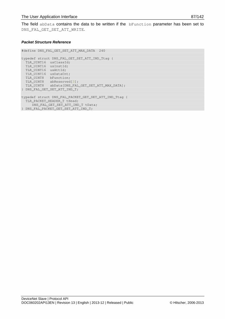
The User Application Interface 87/142
DeviceNet Slave | Protocol API DOC060202API13EN | Revision 13 | English | 2013-12 | Released | Public © Hilscher, 2006-2013
The field abData contains the data to be written if the bFunction parameter has been set to DNS_FAL_GET_SET_ATT_WRITE.
Packet Structure Reference
#define DNS_FAL_GET_SET_ATT_MAX_DATA 240 typedef struct DNS_FAL_GET_SET_ATT_IND_Ttag { TLR_UINT16 usClassId; TLR_UINT16 usInstId; TLR_UINT16 usAttId; TLR_UINT16 usDataCnt; TLR_UINT8 bFunction; TLR_UINT8 abReserved[3]; TLR_UINT8 abData[DNS_FAL_GET_SET_ATT_MAX_DATA]; } DNS_FAL_GET_SET_ATT_IND_T; typedef struct DNS_FAL_PACKET_GET_SET_ATT_IND_Ttag { TLR_PACKET_HEADER_T tHead; DNS_FAL_GET_SET_ATT_IND_T tData; } DNS_FAL_PACKET_GET_SET_ATT_IND_T;

The User Application Interface 88/142
DeviceNet Slave | Protocol API DOC060202API13EN | Revision 13 | English | 2013-12 | Released | Public © Hilscher, 2006-2013
Packet Description
Structure DNS_FAL_PACKET_GET_SET_ATT_IND_T Type: Indication
Variable Type Value / Range Description
tHead - Structure TLR_PACKET_HEADER_T
ulDest UINT32 Destination Queue-Handle of DNS-Task Process Queue
ulSrc UINT32 Source Queue-Handle of AP-Task Process Queue
ulDestId UINT32 0 Destination End Point Identifier, specifying the final receiver of the packet within the Destination Process. Set to 0 for the Initialization Packet
ulSrcId UINT32 0 ... 232-1 Source End Point Identifier, specifying the origin of the packet inside the Source Process
ulLen UINT32
ulId UINT32 0 ... 232-1 Packet Identification as unique number generated by the Source Process of the Packet
ulSta UINT32 See section 6.1 Error Codes of the FAL-Task
ulCmd UINT32 0x2D16 DNS_FAL_CMD_GET_SET_ATT_IND - Command
ulExt UINT32 0 Extension not in use, set to zero for compatibility reasons
ulRout UINT32 × Routing, do not touch
tData - Structure DNS_FAL_GET_SET_ATT_IND_T
usClassId UINT16 4,
6…42,
44...255
Class ID of user application object requested by Master.
usInstId UINT16 0-255 Instance ID of user application object requested by Master.
usAttId UINT16 0-255 Attribute ID of user application object requested by Master.
usDataCnt UINT16 0-240 Data Count of bytes to be read/written by the user application.
bFunction UINT8 1,2 Function (Write/Read)
1: Write
2: Read
abReserved[3] UINT8 Reserved
abData[240] UINT8[] abData array will contain information if the Write function is active.
Table 49: DNS_FAL_CMD_GET_SET_ATT_IND – Indication of Get/Set Attribute Event

The User Application Interface 89/142
DeviceNet Slave | Protocol API DOC060202API13EN | Revision 13 | English | 2013-12 | Released | Public © Hilscher, 2006-2013
Packet Description
Structure DNS_FAL_PACKET_GET_SET_ATT_INDRET_T Type: Indication Return
Variable Type Value / Range Description
tHead - Structure TLR_PACKET_HEADER_T
ulDest UINT32 Destination Queue-Handle of DNS-Task Process Queue
ulSrc UINT32 Source Queue-Handle of AP-Task Process Queue
ulDestId UINT32 0 Destination End Point Identifier, specifying the final receiver of the packet within the Destination Process. Set to 0 for the Initialization Packet
ulSrcId UINT32 0 ... 232-1 Source End Point Identifier, specifying the origin of the packet inside the Source Process
ulLen UINT32
ulId UINT32 0 ... 232-1 Packet Identification as unique number generated by the Source Process of the Packet
ulSta UINT32 See section 6.1 Error Codes of the FAL-Task
ulCmd UINT32 0x2D17 DNS_FAL_CMD_GET_SET_ATT_INDRET - Command
ulExt UINT32 0 Extension not in use, set to zero for compatibility reasons
ulRout UINT32 × Routing, do not touch
tData - Structure DNS_FAL_GET_SET_ATT_IND_T
usClassId UINT16 4,
6…42,
44...255
Class ID of user application object requested by Master.
usInstId UINT16 0-255 Instance ID of user application object requested by Master.
usAttId UINT16 0-255 Attribute ID of user application object requested by Master.
usDataCnt UINT16 0-240 Data Count of bytes to be read/written by the user application.
bFunction UINT8 1,2 Function (Write/Read)
1: Write
2: Read
abReserved[3] UINT8 Reserved
abData[240] UINT8[] Data will contain information if the WRITE function is active.
Table 50: DNS_FAL_CMD_GET_SET_ATT_IND – Indication of Get/Set Attribute Event
The User Application Interface 90/142
DeviceNet Slave | Protocol API DOC060202API13EN | Revision 13 | English | 2013-12 | Released | Public © Hilscher, 2006-2013
5.3.7 DNS_FAL_CMD_GET_SET_ATT_RES/RESRET – Get/Set Attribute Response
The user application may receive unsolicited indications from the DNS-Task. The DNS_FAL_CMD_GET_SET_ATT_IND/INDRET – Get/Set Attribute Indication signals the user application that a Get/Set attribute request was sent by a DeviceNet Master. As discussed above, the user must then provide a response to this command in order to acknowledge its receipt including return data and to avoid the occurrence of a timeout at the master with negative consequences such as possible exclusion from the DeviceNet network.
That means a timeout error will be generated on the master side if a defined time has expired and no answer was received by the DeviceNet master during this period. Because it is now on the user application to send back the corresponding answer message so that the slave device can route it back to the master, the user application should not waste time and send back the message immediately after having finished up the analysis of the indication message.
The various parameters of this packet have the following meaning:
The parameters usClassId, usInstId and usAttId are needed for correctly addressing the attribute to be accessed, i.e. for specifying which attribute of which instance of which object should be read or written. Use the same values as in the indication packet.
The range of the parameter usClassId is restricted to the following numerical values 4, 6 to 42 and 44-255.
The parameter usInstId can be set to all defined instance values for the object chosen with usClassId.
The parameter usAttId can be set to all defined attributes values for the chosen combination of usClassId and usInstId
The parameter bFunction depends whether a read or write request has been issued within the indication. The coding is as follows:
bFunction Parameter
Symbolic constant Assigned numeric value Assigned function
DNS_FAL_GET_SET_ATT_WRITE 1 Write Function
DNS_FAL_GET_SET_ATT_READ 2 Read Function
Table 51: bFunction Parameter
usDataCnt indicates the number of bytes to read or write which may not exceed 240 bytes.
For read access, set it to the value delivered in the indication.
For write access (DNS_FAL_GET_SET_ATT_WRITE, see just below), you should set this value to 0.
bReserved should be zero. It has been introduced for correct byte alignment."
TLR_E_DNS_FAL_GET_STATUS_INVALID_STATUS (0xC0620014L)
which might otherwise occur. This field has only been introduced for correct byte alignment.
The field abData contains the data to be transferred to the master if the bFunction parameter has been set to DNS_FAL_GET_SET_ATT_READ.
These data should be exactly the contents of the requested attribute belonging to the class and instance that has been specified in the indication.
The User Application Interface 91/142
DeviceNet Slave | Protocol API DOC060202API13EN | Revision 13 | English | 2013-12 | Released | Public © Hilscher, 2006-2013
Additionally, the user application has the possibility to signal back access errors back to master, for example if a requested attribute does not exist. This must be done in the bGenErrCode parameter then. See the following table for possible error numbers. DeviceNet allows to send back a general error code and an additional error code in the error response message. All errors in the next table will result an additional error code of 255 except the error value 31. If this error is returned, you can define an additional error code at the bAddErrCode parameter, which is sent back to the master together with the general error code 31.
The bGenErrCode parameter contains an error code which is determined by the CIP specification, see “Table 52: DNS_FAL_CMD_GET_SET_ATT_RES – bGenErrCode General Error Codes” below or “The CIP Networks Library, Volume 1, Appendix B,. General Status Codes”, especially table B-1.1 “CIP General Status Codes” on page 1209.
bGenErrCode
Definition Value Description
DNS_FAL_GET_SET_NO_ERROR 0x00 No error
DNS_FAL_GET_SET_RES_NOT_AVAIL 0x02 Resources unavailable, Class ID invalid
DNS_FAL_GET_SET_SERV_NOT_AVAIL 0x08 Service not available, Read or Write not supported to Class
DNS_FAL_GET_SET_ATTRIB_BAD_VALUE 0x09 Invalid attribute value, attribute not supported
DNS_FAL_GET_SET_ATTRIB_NO_SET 0x0E Attribute not settable, attribute has no write permission.
DNS_FAL_GET_SET_ACCESS_DENIED 0x0F Access denied, general error to deny access
DNS_FAL_GET_SET_STATE_CONFLICT 0x10 State conflict, host state prohibits the command execution
DNS_FAL_GET_SET_NOT_ENOUGH_DATA 0x13 Not enough data received, master has send too less data
DNS_FAL_GET_SET_ATTRIB_NOT_SUP 0x14 Attribute not supported
DNS_FAL_GET_SET_TOO_MUCH_DATA 0x15 Too much data received, master has send too much data
DNS_FAL_GET_SET_VENDOR_SPEC_CODE 0x1F Vendor specific error code. An addition error code can be placed in bAddErrCode.
Table 52: DNS_FAL_CMD_GET_SET_ATT_RES – bGenErrCode General Error Codes
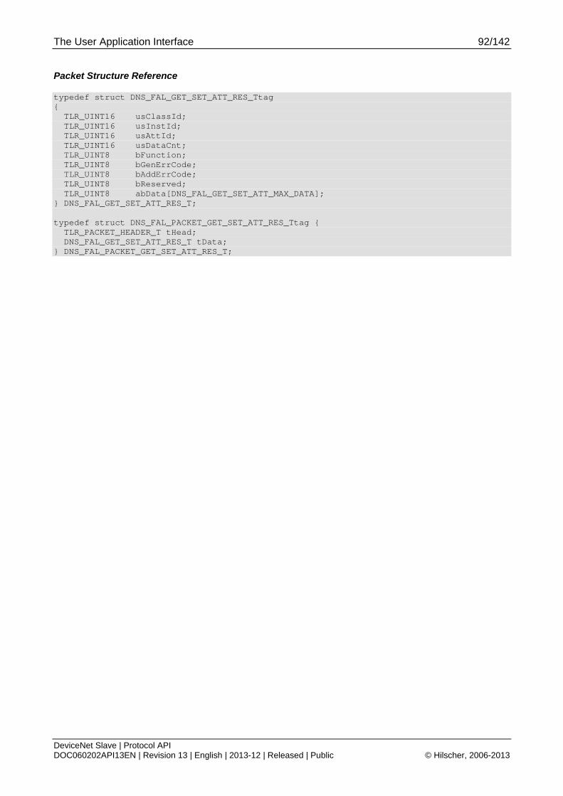
The User Application Interface 92/142
DeviceNet Slave | Protocol API DOC060202API13EN | Revision 13 | English | 2013-12 | Released | Public © Hilscher, 2006-2013
Packet Structure Reference
typedef struct DNS_FAL_GET_SET_ATT_RES_Ttag { TLR_UINT16 usClassId; TLR_UINT16 usInstId; TLR_UINT16 usAttId; TLR_UINT16 usDataCnt; TLR_UINT8 bFunction; TLR_UINT8 bGenErrCode; TLR_UINT8 bAddErrCode; TLR_UINT8 bReserved; TLR_UINT8 abData[DNS_FAL_GET_SET_ATT_MAX_DATA]; } DNS_FAL_GET_SET_ATT_RES_T; typedef struct DNS_FAL_PACKET_GET_SET_ATT_RES_Ttag { TLR_PACKET_HEADER_T tHead; DNS_FAL_GET_SET_ATT_RES_T tData; } DNS_FAL_PACKET_GET_SET_ATT_RES_T;

The User Application Interface 93/142
DeviceNet Slave | Protocol API DOC060202API13EN | Revision 13 | English | 2013-12 | Released | Public © Hilscher, 2006-2013
Packet Description
Structure DNS_FAL_PACKET_GET_SET_ATT_RES_T Type: Response
Variable Type Value / Range Description
tHead - Structure TLR_PACKET_HEADER_T
ulDest UINT32 0x00000020 Destination DPM-Task Process Queue
ulSrc UINT32 0x00000000 Source Queue-Handle
ulDestId UINT32 0 Destination End Point Identifier, specifying the final receiver of the packet within the Destination Process. Set to 0 for the Initialization Packet
ulSrcId UINT32 0 ... 232-1 Source End Point Identifier, specifying the origin of the packet inside the Source Process
ulLen UINT32 sizeof (abData)+12
Value depends on the number of bytes transmitted in abData. The minimum value is 12, the maximum value is 252.
ulId UINT32 0 ... 232-1 Packet Identification as unique number generated by the Source Process of the Packet
ulSta UINT32 See section 6.1 Error Codes of the FAL-Task
ulCmd UINT32 0x2D14 DNS_FAL_CMD_GET_SET_ATT_RES – Command
ulExt UINT32 0 Extension not in use, set to zero for compatibility reasons
ulRout UINT32 × Routing, do not touch
tData - Structure DNS_FAL_GET_SET_ATT_RES_T
usClassId UINT16 4,
6…42,
44...255
Class ID of user application object requested by Master.
usInstId UINT16 0-255 Instance ID of user application object requested by Master.
usAttId UINT16 0-255 Attribute ID of user application object requested by Master.
usDataCnt UINT16 0-240 Data Count of bytes to be read/written by the user application.
bFunction UINT8 1,2 Function (Write/Read)
1: Write
2: Read
bGenErrCode UINT8 0-255 DeviceNet General error code to return by the user See Table 52: DNS_FAL_CMD_GET_SET_ATT_RES – bGenErrCode General Error Codes
bAddErrCode UINT8 0-255 DeviceNet Additional error code – User specific. See description above.
bReserved UINT8 Reserved, set to zero
abData[240] UINT8[] Data will contain information if the READ function is active.
Table 53: DNS_FAL_CMD_GET_SET_ATT_RES – Get/Set Attribute Response

The User Application Interface 94/142
DeviceNet Slave | Protocol API DOC060202API13EN | Revision 13 | English | 2013-12 | Released | Public © Hilscher, 2006-2013
Packet Structure Reference
typedef struct DNS_FAL_GET_SET_ATT_RESRET_Ttag { TLR_UINT16 usClassId; TLR_UINT16 usInstId; TLR_UINT16 usAttId; TLR_UINT16 usDataCnt; TLR_UINT8 bFunction; TLR_UINT8 bGenErrCode; TLR_UINT8 bAddErrCode; TLR_UINT8 bReserved; } DNS_FAL_GET_SET_ATT_RESRET_T; typedef struct DNS_FAL_PACKET_GET_SET_ATT_RESRET_Ttag { TLR_PACKET_HEADER_T tHead; DNS_FAL_GET_SET_ATT_RESRET_T tData; } DNS_FAL_PACKET_GET_SET_ATT_RESRET_T;
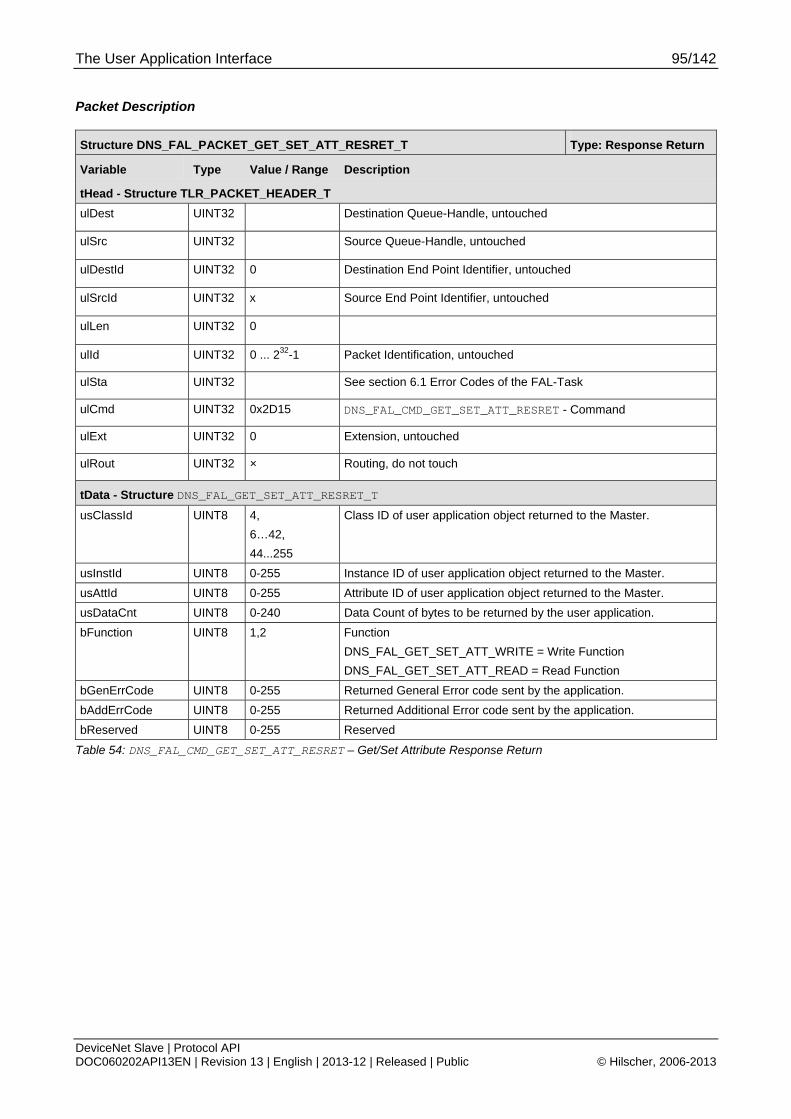
The User Application Interface 95/142
DeviceNet Slave | Protocol API DOC060202API13EN | Revision 13 | English | 2013-12 | Released | Public © Hilscher, 2006-2013
Packet Description
Structure DNS_FAL_PACKET_GET_SET_ATT_RESRET_T Type: Response Return
Variable Type Value / Range Description
tHead - Structure TLR_PACKET_HEADER_T
ulDest UINT32 Destination Queue-Handle, untouched
ulSrc UINT32 Source Queue-Handle, untouched
ulDestId UINT32 0 Destination End Point Identifier, untouched
ulSrcId UINT32 x Source End Point Identifier, untouched
ulLen UINT32 0
ulId UINT32 0 ... 232-1 Packet Identification, untouched
ulSta UINT32 See section 6.1 Error Codes of the FAL-Task
ulCmd UINT32 0x2D15 DNS_FAL_CMD_GET_SET_ATT_RESRET - Command
ulExt UINT32 0 Extension, untouched
ulRout UINT32 × Routing, do not touch
tData - Structure DNS_FAL_GET_SET_ATT_RESRET_T
usClassId UINT8 4,
6…42,
44...255
Class ID of user application object returned to the Master.
usInstId UINT8 0-255 Instance ID of user application object returned to the Master.
usAttId UINT8 0-255 Attribute ID of user application object returned to the Master.
usDataCnt UINT8 0-240 Data Count of bytes to be returned by the user application.
bFunction UINT8 1,2 Function
DNS_FAL_GET_SET_ATT_WRITE = Write Function
DNS_FAL_GET_SET_ATT_READ = Read Function
bGenErrCode UINT8 0-255 Returned General Error code sent by the application.
bAddErrCode UINT8 0-255 Returned Additional Error code sent by the application.
bReserved UINT8 0-255 Reserved
Table 54: DNS_FAL_CMD_GET_SET_ATT_RESRET – Get/Set Attribute Response Return
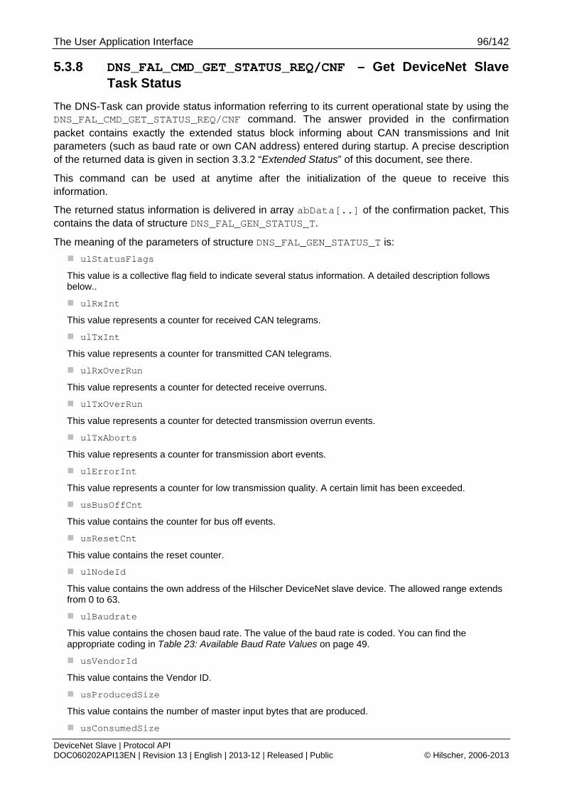
The User Application Interface 96/142
DeviceNet Slave | Protocol API DOC060202API13EN | Revision 13 | English | 2013-12 | Released | Public © Hilscher, 2006-2013
5.3.8 DNS_FAL_CMD_GET_STATUS_REQ/CNF – Get DeviceNet Slave Task Status
The DNS-Task can provide status information referring to its current operational state by using the DNS_FAL_CMD_GET_STATUS_REQ/CNF command. The answer provided in the confirmation packet contains exactly the extended status block informing about CAN transmissions and Init parameters (such as baud rate or own CAN address) entered during startup. A precise description of the returned data is given in section 3.3.2 “Extended Status” of this document, see there.
This command can be used at anytime after the initialization of the queue to receive this information.
The returned status information is delivered in array abData[..] of the confirmation packet, This contains the data of structure DNS_FAL_GEN_STATUS_T.
The meaning of the parameters of structure DNS_FAL_GEN_STATUS_T is:
ulStatusFlags
This value is a collective flag field to indicate several status information. A detailed description follows below..
ulRxInt
This value represents a counter for received CAN telegrams.
ulTxInt
This value represents a counter for transmitted CAN telegrams.
ulRxOverRun
This value represents a counter for detected receive overruns.
ulTxOverRun
This value represents a counter for detected transmission overrun events.
ulTxAborts
This value represents a counter for transmission abort events.
ulErrorInt
This value represents a counter for low transmission quality. A certain limit has been exceeded.
usBusOffCnt
This value contains the counter for bus off events.
usResetCnt
This value contains the reset counter.
ulNodeId
This value contains the own address of the Hilscher DeviceNet slave device. The allowed range extends from 0 to 63.
ulBaudrate
This value contains the chosen baud rate. The value of the baud rate is coded. You can find the appropriate coding in Table 23: Available Baud Rate Values on page 49.
usVendorId
This value contains the Vendor ID.
usProducedSize
This value contains the number of master input bytes that are produced.
usConsumedSize
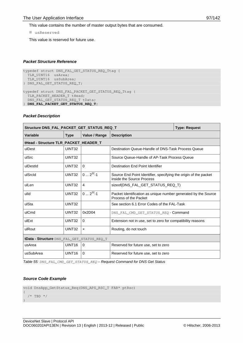
The User Application Interface 97/142
DeviceNet Slave | Protocol API DOC060202API13EN | Revision 13 | English | 2013-12 | Released | Public © Hilscher, 2006-2013
This value contains the number of master output bytes that are consumed.
usReserved
This value is reserved for future use.
Packet Structure Reference
typedef struct DNS_FAL_GET_STATUS_REQ_Ttag { TLR_UINT16 usArea; TLR_UINT16 usSubArea; } DNS_FAL_GET_STATUS_REQ_T; typedef struct DNS_FAL_PACKET_GET_STATUS_REQ_Ttag { TLR_PACKET_HEADER_T tHead; DNS_FAL_GET_STATUS_REQ_T tData; } DNS_FAL_PACKET_GET_STATUS_REQ_T;
Packet Description
Structure DNS_FAL_PACKET_GET_STATUS_REQ_T Type: Request
Variable Type Value / Range Description
tHead - Structure TLR_PACKET_HEADER_T
ulDest UINT32 Destination Queue-Handle of DNS-Task Process Queue
ulSrc UINT32 Source Queue-Handle of AP-Task Process Queue
ulDestId UINT32 0 Destination End Point Identifier
ulSrcId UINT32 0 ... 232-1 Source End Point Identifier, specifying the origin of the packet inside the Source Process
ulLen UINT32 4 sizeof(DNS_FAL_GET_STATUS_REQ_T)
ulId UINT32 0 ... 232-1 Packet Identification as unique number generated by the Source Process of the Packet
ulSta UINT32 See section 6.1 Error Codes of the FAL-Task
ulCmd UINT32 0x2D04 DNS_FAL_CMD_GET_STATUS_REQ - Command
ulExt UINT32 0 Extension not in use, set to zero for compatibility reasons
ulRout UINT32 × Routing, do not touch
tData - Structure DNS_FAL_GET_STATUS_REQ_T
usArea UINT16 0 Reserved for future use, set to zero
usSubArea UINT16 0 Reserved for future use, set to zero
Table 55: DNS_FAL_CMD_GET_STATUS_REQ – Request Command for DNS Get Status
Source Code Example
void DnsApp_GetStatus_Req(DNS_APS_RSC_T FAR* ptRsc) { /* TBD */ }

The User Application Interface 98/142
DeviceNet Slave | Protocol API DOC060202API13EN | Revision 13 | English | 2013-12 | Released | Public © Hilscher, 2006-2013
Packet Structure Reference
typedef struct DNS_FAL_GEN_STATUS_T { TLR_UINT32 ulStatusFlags; TLR_UINT32 ulRxInt; TLR_UINT32 ulTxInt; TLR_UINT32 ulRxOverRun; TLR_UINT32 ulTxOverRun; TLR_UINT32 ulTxAborts; TLR_UINT32 ulErrorInt; TLR_UINT32 ulBusOffCnt; TLR_UINT32 ulResetCnt; TLR_UINT32 ulNodeId; TLR_UINT32 ulBaudrate; TLR_UINT16 usVendorId; TLR_UINT16 usProducedSize; TLR_UINT16 usConsumedSize; TLR_UINT16 usReserved; } DNS_FAL_GEN_STATUS_T; #define DNS_FAL_GET_STATUS_CNF_MAX_DATA (256) typedef struct DNS_FAL_GET_STATUS_CNF_Ttag { TLR_UINT16 usArea; TLR_UINT16 usSubArea; TLR_UINT8 abData[DNS_FAL_GET_STATUS_CNF_MAX_DATA]; } DNS_FAL_GET_STATUS_CNF_T; #define DNS_FAL_GET_STATUS_CNF_SIZE (sizeof(DNS_FAL_GET_STATUS_CNF_T)-DNS_FAL_GET_STATUS_CNF_MAX_DATA) typedef struct DNS_FAL_PACKET_GET_STATUS_CNF_Ttag { TLR_PACKET_HEADER_T tHead; DNS_FAL_GET_STATUS_CNF_T tData; } DNS_FAL_PACKET_GET_STATUS_CNF_T;

The User Application Interface 99/142
DeviceNet Slave | Protocol API DOC060202API13EN | Revision 13 | English | 2013-12 | Released | Public © Hilscher, 2006-2013
The meaning of the ulStatusFlags are following:
/* Status flags with command DNS_FAL_CMD_GET_STATUS_REQ */ #define MSK_DNS_STA_FLAG_BUS_PRM_VALID 0x00000001 #define MSK_DNS_STA_FLAG_BUS_START 0x00000002 #define MSK_DNS_STA_FLAG_24V_NETWORK_POWER 0x00000004 #define MSK_DNS_STA_FLAG_NETWORK_STATE_ONLINE 0x00000008 #define MSK_DNS_STA_FLAG_RX_IDLE 0x00000010 #define MSK_DNS_STA_FLAG_ERR_DUP_MAC_ID 0x00010000 #define MSK_DNS_STA_FLAG_ERR_BUS_OFF 0x00020000 #define MSK_DNS_STA_FLAG_RESERVED 0xFFFCFFF0
MSK_DNS_STA_FLAG_BUS_PRM_VALID
This Flag means that the stack has received a valid configuration.
MSK_DNS_STA_FLAG_BUS_START
This Flag indicates that the application task has allowed the stack to start network communication by setting the operate mode to RUN. (see. command DNS_FAL_CMD_SET_MODE_REQ).
MSK_DNS_STA_FLAG_24V_NETWORK_POWER
This Flag indicates if the 24V Network Power is present or not. The 24V Network Power is a basic condition for DeviceNet to start any network activity. If this flag is not set, the device will not be present on the network or start any network activity.
MSK_DNS_STA_FLAG_NETWORK_STATE_ONLINE
This flag indicates if the stack has access to the network. This means that the 24V network power is present and the stack was able to send the two duplicate MAC_ID frames to the bus and is in general ready to communicate with the master.
MSK_DNS_STA_FLAG_RX_IDLE
This flag indicates the DeviceNet master has send a receive_idle telegram to the slave.
MSK_DNS_STA_FLAG_ERR_DUP_MAC_ID
This flag indicates that the slave has found another device with the same network address on the bus. The slave stops any further operation and must be reconfigured and reset.
MSK_DNS_STA_FLAG_ERR_BUS_OFF
This flag indicates that the slave has detected a CAN “BUS_OFF” event. This indicates for heavy physical can errors e.g. bus short circuits. When the slave has detected this event, then the slave stops any further operation an goes into a major fault. The slave must be reset.
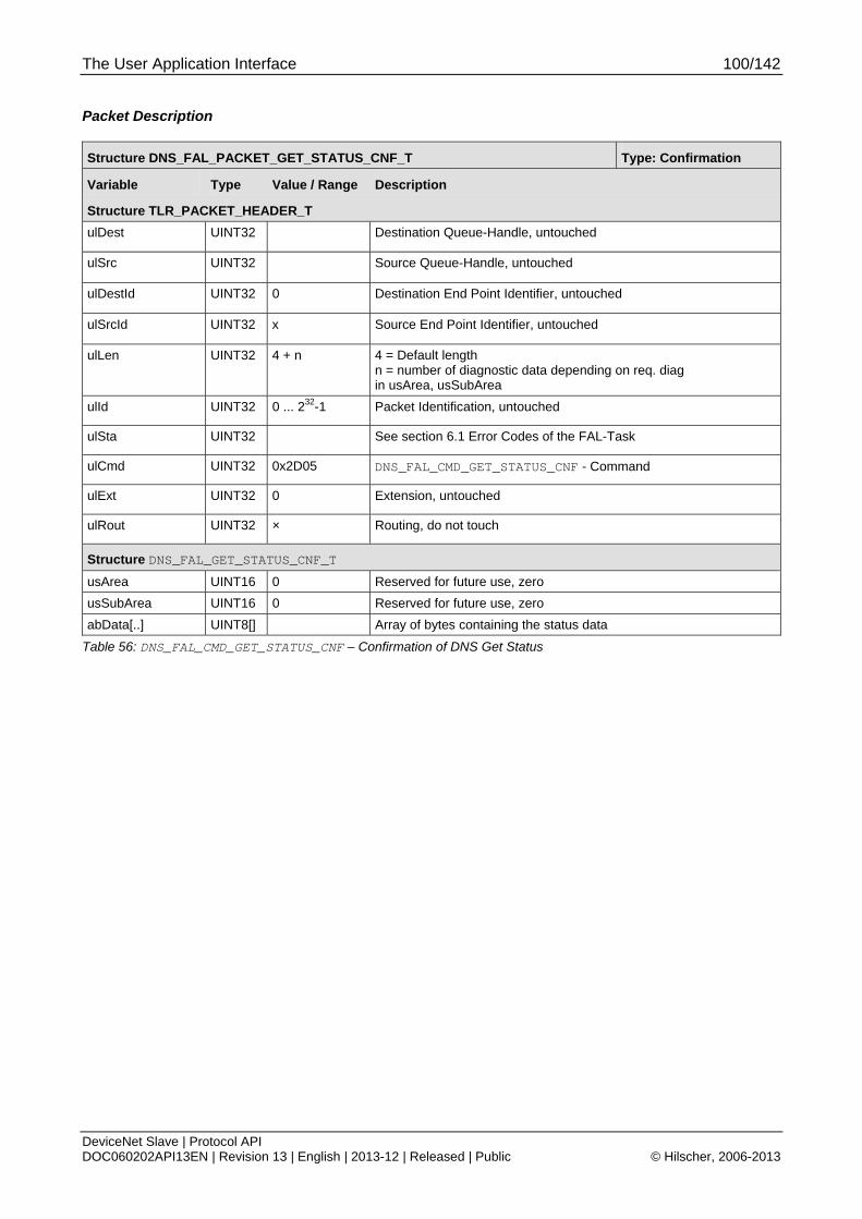
The User Application Interface 100/142
DeviceNet Slave | Protocol API DOC060202API13EN | Revision 13 | English | 2013-12 | Released | Public © Hilscher, 2006-2013
Packet Description
Structure DNS_FAL_PACKET_GET_STATUS_CNF_T Type: Confirmation
Variable Type Value / Range Description
Structure TLR_PACKET_HEADER_T
ulDest UINT32 Destination Queue-Handle, untouched
ulSrc UINT32 Source Queue-Handle, untouched
ulDestId UINT32 0 Destination End Point Identifier, untouched
ulSrcId UINT32 x Source End Point Identifier, untouched
ulLen UINT32 4 + n 4 = Default length n = number of diagnostic data depending on req. diag in usArea, usSubArea
ulId UINT32 0 ... 232-1 Packet Identification, untouched
ulSta UINT32 See section 6.1 Error Codes of the FAL-Task
ulCmd UINT32 0x2D05 DNS_FAL_CMD_GET_STATUS_CNF - Command
ulExt UINT32 0 Extension, untouched
ulRout UINT32 × Routing, do not touch
Structure DNS_FAL_GET_STATUS_CNF_T
usArea UINT16 0 Reserved for future use, zero
usSubArea UINT16 0 Reserved for future use, zero
abData[..] UINT8[] Array of bytes containing the status data
Table 56: DNS_FAL_CMD_GET_STATUS_CNF – Confirmation of DNS Get Status
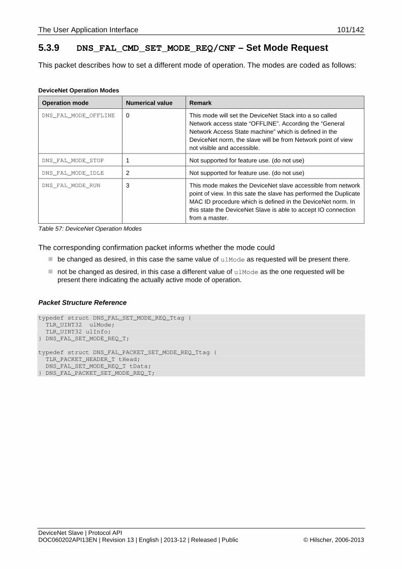
The User Application Interface 101/142
DeviceNet Slave | Protocol API DOC060202API13EN | Revision 13 | English | 2013-12 | Released | Public © Hilscher, 2006-2013
5.3.9 DNS_FAL_CMD_SET_MODE_REQ/CNF – Set Mode Request
This packet describes how to set a different mode of operation. The modes are coded as follows:
DeviceNet Operation Modes
Operation mode Numerical value Remark
DNS_FAL_MODE_OFFLINE 0 This mode will set the DeviceNet Stack into a so called Network access state “OFFLINE”. According the “General Network Access State machine” which is defined in the DeviceNet norm, the slave will be from Network point of view not visible and accessible.
DNS_FAL_MODE_STOP 1 Not supported for feature use. (do not use)
DNS_FAL_MODE_IDLE 2 Not supported for feature use. (do not use)
DNS_FAL_MODE_RUN 3 This mode makes the DeviceNet slave accessible from network point of view. In this sate the slave has performed the Duplicate MAC ID procedure which is defined in the DeviceNet norm. In this state the DeviceNet Slave is able to accept IO connection from a master.
Table 57: DeviceNet Operation Modes
The corresponding confirmation packet informs whether the mode could
be changed as desired, in this case the same value of ulMode as requested will be present there.
not be changed as desired, in this case a different value of ulMode as the one requested will be present there indicating the actually active mode of operation.
Packet Structure Reference
typedef struct DNS_FAL_SET_MODE_REQ_Ttag { TLR_UINT32 ulMode; TLR_UINT32 ulInfo; } DNS_FAL_SET_MODE_REQ_T; typedef struct DNS_FAL_PACKET_SET_MODE_REQ_Ttag { TLR_PACKET_HEADER_T tHead; DNS_FAL_SET_MODE_REQ_T tData; } DNS_FAL_PACKET_SET_MODE_REQ_T;
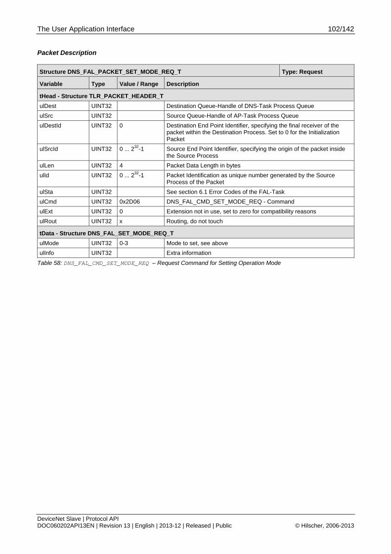
The User Application Interface 102/142
DeviceNet Slave | Protocol API DOC060202API13EN | Revision 13 | English | 2013-12 | Released | Public © Hilscher, 2006-2013
Packet Description
Structure DNS_FAL_PACKET_SET_MODE_REQ_T Type: Request
Variable Type Value / Range Description
tHead - Structure TLR_PACKET_HEADER_T
ulDest UINT32 Destination Queue-Handle of DNS-Task Process Queue
ulSrc UINT32 Source Queue-Handle of AP-Task Process Queue
ulDestId UINT32 0 Destination End Point Identifier, specifying the final receiver of the packet within the Destination Process. Set to 0 for the Initialization Packet
ulSrcId UINT32 0 ... 232-1 Source End Point Identifier, specifying the origin of the packet inside the Source Process
ulLen UINT32 4 Packet Data Length in bytes
ulId UINT32 0 ... 232-1 Packet Identification as unique number generated by the Source Process of the Packet
ulSta UINT32 See section 6.1 Error Codes of the FAL-Task
ulCmd UINT32 0x2D06 DNS_FAL_CMD_SET_MODE_REQ - Command
ulExt UINT32 0 Extension not in use, set to zero for compatibility reasons
ulRout UINT32 x Routing, do not touch
tData - Structure DNS_FAL_SET_MODE_REQ_T
ulMode UINT32 0-3 Mode to set, see above
ulInfo UINT32 Extra information
Table 58: DNS_FAL_CMD_SET_MODE_REQ – Request Command for Setting Operation Mode
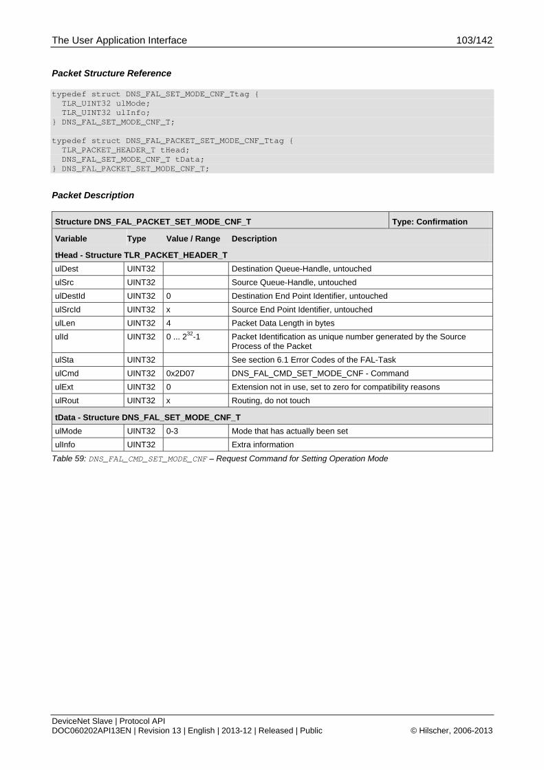
The User Application Interface 103/142
DeviceNet Slave | Protocol API DOC060202API13EN | Revision 13 | English | 2013-12 | Released | Public © Hilscher, 2006-2013
Packet Structure Reference
typedef struct DNS_FAL_SET_MODE_CNF_Ttag { TLR_UINT32 ulMode; TLR_UINT32 ulInfo; } DNS_FAL_SET_MODE_CNF_T; typedef struct DNS_FAL_PACKET_SET_MODE_CNF_Ttag { TLR_PACKET_HEADER_T tHead; DNS_FAL_SET_MODE_CNF_T tData; } DNS_FAL_PACKET_SET_MODE_CNF_T;
Packet Description
Structure DNS_FAL_PACKET_SET_MODE_CNF_T Type: Confirmation
Variable Type Value / Range Description
tHead - Structure TLR_PACKET_HEADER_T
ulDest UINT32 Destination Queue-Handle, untouched
ulSrc UINT32 Source Queue-Handle, untouched
ulDestId UINT32 0 Destination End Point Identifier, untouched
ulSrcId UINT32 x Source End Point Identifier, untouched
ulLen UINT32 4 Packet Data Length in bytes
ulId UINT32 0 ... 232-1 Packet Identification as unique number generated by the Source Process of the Packet
ulSta UINT32 See section 6.1 Error Codes of the FAL-Task
ulCmd UINT32 0x2D07 DNS_FAL_CMD_SET_MODE_CNF - Command
ulExt UINT32 0 Extension not in use, set to zero for compatibility reasons
ulRout UINT32 x Routing, do not touch
tData - Structure DNS_FAL_SET_MODE_CNF_T
ulMode UINT32 0-3 Mode that has actually been set
ulInfo UINT32 Extra information
Table 59: DNS_FAL_CMD_SET_MODE_CNF – Request Command for Setting Operation Mode

The User Application Interface 104/142
DeviceNet Slave | Protocol API DOC060202API13EN | Revision 13 | English | 2013-12 | Released | Public © Hilscher, 2006-2013
5.3.10 DNS_FAL_CMD_CLR_CONFIG_REQ/CNF – Clear Configuration Request
This packet clears the configuration data stored in the device.
Packet Structure Reference
typedef struct DNS_FAL_SDU_CLR_CONFIG_REQ_Ttag { TLR_UINT32 ulCfgArea; }DNS_FAL_SDU_CLR_CONFIG_REQ_T; typedef struct DNS_FAL_PACKET_CLR_CONFIG_REQ_Ttag { TLR_PACKET_HEADER_T tHead; DNS_FAL_SDU_CLR_CONFIG_REQ_T tData; } DNS_FAL_PACKET_CLR_CONFIG_REQ_T;
Packet Description
Structure DNS_FAL_PACKET_CLR_CONFIG_REQ_T Type: Request
Variable Type Value / Range Description
tHead - Structure TLR_PACKET_HEADER_T
ulDest UINT32 Destination Queue-Handle of DNS-Task Process Queue
ulSrc UINT32 Source Queue-Handle of AP-Task Process Queue
ulDestId UINT32 0 Destination End Point Identifier
ulSrcId UINT32 0 ... 232-1 Source End Point Identifier, specifying the origin of the packet inside the Source Process
ulLen UINT32 4 Packet Data Length in bytes
ulId UINT32 0 ... 232-1 Packet Identification as unique number generated by the Source Process of the Packet
ulSta UINT32 See section 6.1 Error Codes of the FAL-Task
ulCmd UINT32 0x2D08 DNS_FAL_CMD_CLR_CONFIG_REQ - Command
ulExt UINT32 0 Extension not in use, set to zero for compatibility reasons
ulRout UINT32 x Routing, do not touch
tData - Structure DNS_FAL_SDU_CLR_CONFIG_REQ_T
ulCfgArea UINT32 0 0 = Clear all configuration data
Table 60: DNS_FAL_CMD_CLR_CONFIG_REQ - Clear Configuration Request
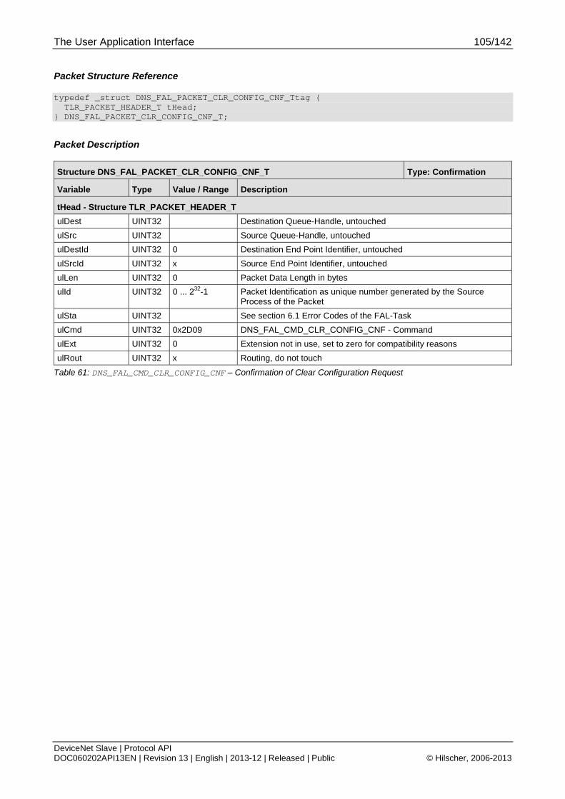
The User Application Interface 105/142
DeviceNet Slave | Protocol API DOC060202API13EN | Revision 13 | English | 2013-12 | Released | Public © Hilscher, 2006-2013
Packet Structure Reference
typedef _struct DNS_FAL_PACKET_CLR_CONFIG_CNF_Ttag { TLR_PACKET_HEADER_T tHead; } DNS_FAL_PACKET_CLR_CONFIG_CNF_T;
Packet Description
Structure DNS_FAL_PACKET_CLR_CONFIG_CNF_T Type: Confirmation
Variable Type Value / Range Description
tHead - Structure TLR_PACKET_HEADER_T
ulDest UINT32 Destination Queue-Handle, untouched
ulSrc UINT32 Source Queue-Handle, untouched
ulDestId UINT32 0 Destination End Point Identifier, untouched
ulSrcId UINT32 x Source End Point Identifier, untouched
ulLen UINT32 0 Packet Data Length in bytes
ulId UINT32 0 ... 232-1 Packet Identification as unique number generated by the Source Process of the Packet
ulSta UINT32 See section 6.1 Error Codes of the FAL-Task
ulCmd UINT32 0x2D09 DNS_FAL_CMD_CLR_CONFIG_CNF - Command
ulExt UINT32 0 Extension not in use, set to zero for compatibility reasons
ulRout UINT32 x Routing, do not touch
Table 61: DNS_FAL_CMD_CLR_CONFIG_CNF – Confirmation of Clear Configuration Request
The User Application Interface 106/142
DeviceNet Slave | Protocol API DOC060202API13EN | Revision 13 | English | 2013-12 | Released | Public © Hilscher, 2006-2013
5.3.11 DNS_FAL_CMD_LED_STATE_IND – LED State Indication
This packet indicates a change in the LED state. To receive this indication to the AP task the corresponding enable flag ‘DNS_FAL_EVENT_LED_STATE_IND’ must be set within the parameter ‘ulMode’ of the command ‘DNS_FAL_CMD_APP_REQ’.
The type of the affected LED is indicated by parameter ulLedType in the following way:
Value of ulLedType Meaning
1 NS LED
Table 62: Meaning of ulLedType
The DNS task itself can provide only the LED information according to the network access state. The network access state is represented by a so called Network Status LED (NS LED). The application is responsible to combine this information with the Module Status information and control the connected LED’s according the “Chapter 9-2 Indicators”.
The mode of the affected LED is indicated by parameter ulLedMode according to this table:
Value of ulLedMode Meaning
1 Static
2 Flash
Table 63: Meaning of ulLedMode
The color of the affected LED is indicated by parameter ulLedColor as follows:
Value of ulLedColor Meaning
1 Off
2 Green
3 Red
Table 64: Meaning of ulLedColor
The response packet without parameters needs to be sent to receive further change of state indications of the LED.
Note: The power up sequence of a DeviceNet LED is not indicated to the AP task, because the stack task does not know about the used DeviceNet LED system, if it is an combined module network status LED (MNS) or if there are two separate LED’s ( NS + MS) to indicate the device state. This handling must be done in the AP task context.

The User Application Interface 107/142
DeviceNet Slave | Protocol API DOC060202API13EN | Revision 13 | English | 2013-12 | Released | Public © Hilscher, 2006-2013
Packet Structure Reference
/****************************************/ /* DNS_FAL_CMD_LED_STATE_IND Structure */ typedef struct DNS_FAL_LED_STATE_Ttag { TLR_UINT32 ulLedType; /* DNS_FAL_LED_TYPE_NS */ TLR_UINT32 ulLedMode; /* DNS_FAL_LED_MODE_STATIC ,.._FLASH */ TLR_UINT32 ulLedColor; /* DNS_FAL_LED_COLOR_OFF ,..GREEN, ..RED */ } DNS_FAL_LED_STATE_T; #define DNS_FAL_LED_STATE_IND_SIZE (sizeof(DNS_FAL_LED_STATE_T)) typedef struct DNS_FAL_PACKET_LED_STATE_IND_Ttag { TLR_PACKET_HEADER_T tHead; DNS_FAL_LED_STATE_T tData; } DNS_FAL_PACKET_LED_STATE_IND_T;
Packet Description
Structure DNS_FAL_PACKET_LED_STATE_IND_T Type: Indication
Variable Type Value / Range Description
tHead - Structure TLR_PACKET_HEADER_T
ulDest UINT32 Destination Queue-Handle of DNS-Task Process Queue
ulSrc UINT32 Source Queue-Handle of AP-Task Process Queue
ulDestId UINT32 0 Destination End Point Identifier, specifying the final receiver of the packet within the Destination Process. Set to 0 for the Initialization Packet
ulSrcId UINT32 0 ... 232-1 Source End Point Identifier, specifying the origin of the packet inside the Source Process
ulLen UINT32 12 Packet Data Length in bytes
ulId UINT32 0 ... 232-1 Packet Identification as unique number generated by the Source Process of the Packet
ulSta UINT32 See section 6.1 Error Codes of the FAL-Task
ulCmd UINT32 0x2D1C DNS_FAL_CMD_LED_STATE_IND - Command
ulExt UINT32 0 Extension not in use, set to zero for compatibility reasons
ulRout UINT32 x Routing, do not touch
tData - Structure DNS_FAL_LED_STATE_T
ulLedType UINT32 1 LED Type (NS = 1)
ulLedMode UINT32 1…2 LED Mode (STATIC = 1, FLASH = 2)
ulLedColor UINT32 1…3 Color of LED (OFF = 1, GREEN = 2, RED = 3)
Table 65: DNS_FAL_CMD_LED_STATE_IND – LED State Indication

The User Application Interface 108/142
DeviceNet Slave | Protocol API DOC060202API13EN | Revision 13 | English | 2013-12 | Released | Public © Hilscher, 2006-2013
Packet Structure Reference
/****************************************/ /* DNS_FAL_CMD_LED_STATE_RES Structure */ typedef struct DNS_FAL_PACKET_LED_STATE_RES_Ttag { TLR_PACKET_HEADER_T tHead; } DNS_FAL_PACKET_LED_STATE_RES_T;
Packet Description
Structure DNS_FAL_PACKET_LED_STATE_RES_T Type: Response
Variable Type Value / Range Description
tHead - Structure TLR_PACKET_HEADER_T
ulDest UINT32 Destination DPM-Task Process Queue
ulSrc UINT32 Source Queue-Handle
ulDestId UINT32 0 Destination End Point Identifier, specifying the final receiver of the packet within the Destination Process. Set to 0 for the Initialization Packet
ulSrcId UINT32 0 ... 232-1 Source End Point Identifier, specifying the origin of the packet inside the Source Process
ulLen UINT32 Packet Data Length in bytes
ulId UINT32 0 ... 232-1 Packet Identification as unique number generated by the Source Process of the Packet
ulSta UINT32 See section 6.1 Error Codes of the FAL-Task
ulCmd UINT32 0x2D1D DNS_FAL_CMD_LED_STATE_RES - Command
ulExt UINT32 0 Extension not in use, set to zero for compatibility reasons
ulRout UINT32 x Routing, do not touch
Table 66: DNS_FAL_CMD_LED_STATE_RES – LED State Response
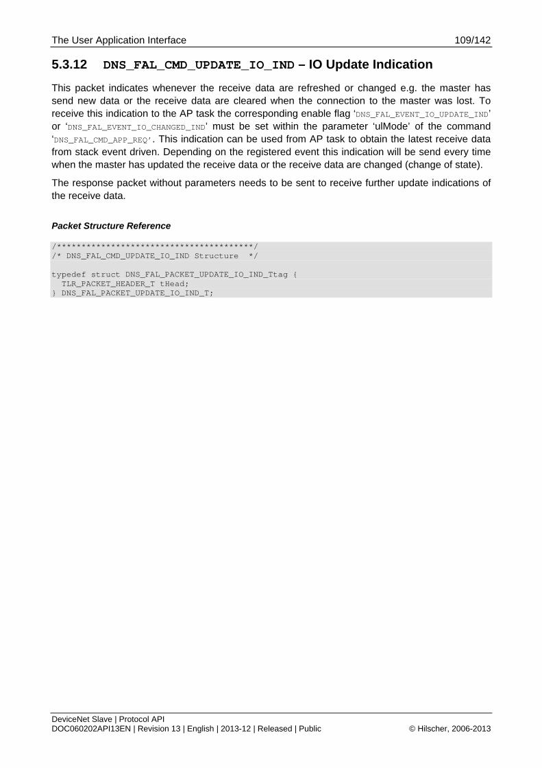
The User Application Interface 109/142
DeviceNet Slave | Protocol API DOC060202API13EN | Revision 13 | English | 2013-12 | Released | Public © Hilscher, 2006-2013
5.3.12 DNS_FAL_CMD_UPDATE_IO_IND – IO Update Indication
This packet indicates whenever the receive data are refreshed or changed e.g. the master has send new data or the receive data are cleared when the connection to the master was lost. To receive this indication to the AP task the corresponding enable flag ‘DNS_FAL_EVENT_IO_UPDATE_IND’ or ‘DNS_FAL_EVENT_IO_CHANGED_IND’ must be set within the parameter ‘ulMode’ of the command ‘DNS_FAL_CMD_APP_REQ’. This indication can be used from AP task to obtain the latest receive data from stack event driven. Depending on the registered event this indication will be send every time when the master has updated the receive data or the receive data are changed (change of state).
The response packet without parameters needs to be sent to receive further update indications of the receive data.
Packet Structure Reference
/****************************************/ /* DNS_FAL_CMD_UPDATE_IO_IND Structure */ typedef struct DNS_FAL_PACKET_UPDATE_IO_IND_Ttag { TLR_PACKET_HEADER_T tHead; } DNS_FAL_PACKET_UPDATE_IO_IND_T;
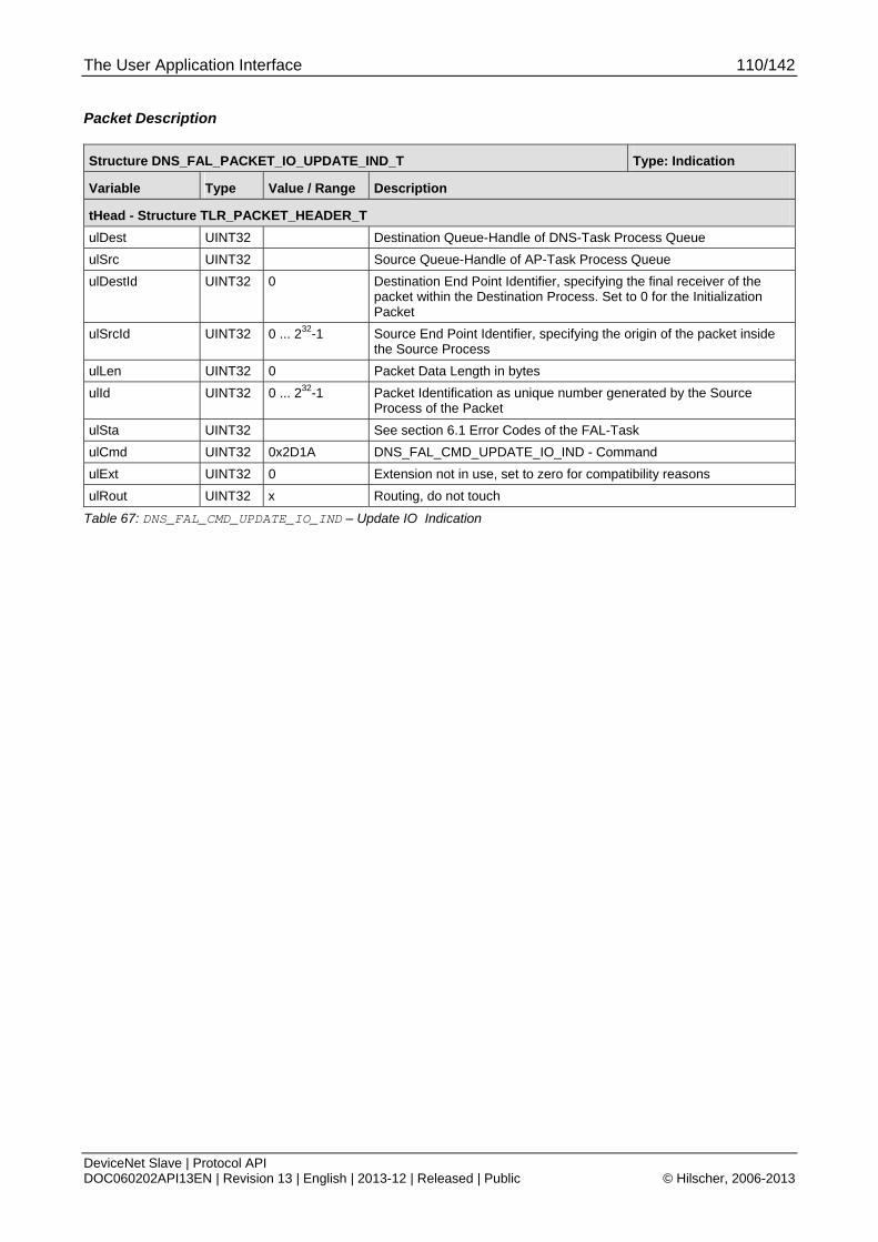
The User Application Interface 110/142
DeviceNet Slave | Protocol API DOC060202API13EN | Revision 13 | English | 2013-12 | Released | Public © Hilscher, 2006-2013
Packet Description
Structure DNS_FAL_PACKET_IO_UPDATE_IND_T Type: Indication
Variable Type Value / Range Description
tHead - Structure TLR_PACKET_HEADER_T
ulDest UINT32 Destination Queue-Handle of DNS-Task Process Queue
ulSrc UINT32 Source Queue-Handle of AP-Task Process Queue
ulDestId UINT32 0 Destination End Point Identifier, specifying the final receiver of the packet within the Destination Process. Set to 0 for the Initialization Packet
ulSrcId UINT32 0 ... 232-1 Source End Point Identifier, specifying the origin of the packet inside the Source Process
ulLen UINT32 0 Packet Data Length in bytes
ulId UINT32 0 ... 232-1 Packet Identification as unique number generated by the Source Process of the Packet
ulSta UINT32 See section 6.1 Error Codes of the FAL-Task
ulCmd UINT32 0x2D1A DNS_FAL_CMD_UPDATE_IO_IND - Command
ulExt UINT32 0 Extension not in use, set to zero for compatibility reasons
ulRout UINT32 x Routing, do not touch
Table 67: DNS_FAL_CMD_UPDATE_IO_IND – Update IO Indication
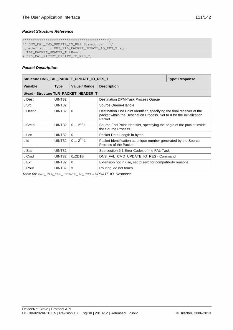
The User Application Interface 111/142
DeviceNet Slave | Protocol API DOC060202API13EN | Revision 13 | English | 2013-12 | Released | Public © Hilscher, 2006-2013
Packet Structure Reference
/****************************************/ /* DNS_FAL_CMD_UPDATE_IO_RES Structure */ typedef struct DNS_FAL_PACKET_UPDATE_IO_RES_Ttag { TLR_PACKET_HEADER_T tHead; } DNS_FAL_PACKET_UPDATE_IO_RES_T;
Packet Description
Structure DNS_FAL_PACKET_UPDATE_IO_RES_T Type: Response
Variable Type Value / Range Description
tHead - Structure TLR_PACKET_HEADER_T
ulDest UINT32 Destination DPM-Task Process Queue
ulSrc UINT32 Source Queue-Handle
ulDestId UINT32 0 Destination End Point Identifier, specifying the final receiver of the packet within the Destination Process. Set to 0 for the Initialization Packet
ulSrcId UINT32 0 ... 232-1 Source End Point Identifier, specifying the origin of the packet inside the Source Process
ulLen UINT32 0 Packet Data Length in bytes
ulId UINT32 0 ... 232-1 Packet Identification as unique number generated by the Source Process of the Packet
ulSta UINT32 See section 6.1 Error Codes of the FAL-Task
ulCmd UINT32 0x2D1B DNS_FAL_CMD_UPDATE_IO_RES - Command
ulExt UINT32 0 Extension not in use, set to zero for compatibility reasons
ulRout UINT32 x Routing, do not touch
Table 68: DNS_FAL_CMD_UPDATE_IO_RES – UPDATE IO Response
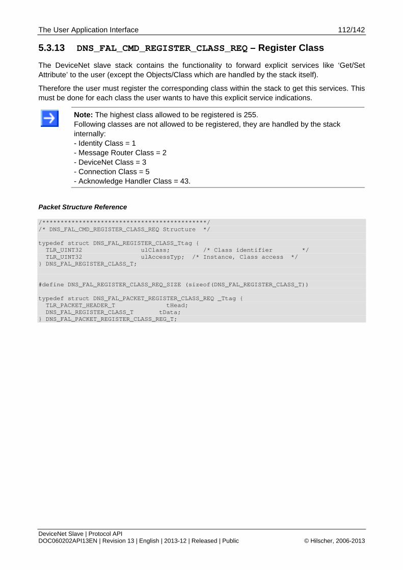
The User Application Interface 112/142
DeviceNet Slave | Protocol API DOC060202API13EN | Revision 13 | English | 2013-12 | Released | Public © Hilscher, 2006-2013
5.3.13 DNS_FAL_CMD_REGISTER_CLASS_REQ – Register Class
The DeviceNet slave stack contains the functionality to forward explicit services like ‘Get/Set Attribute’ to the user (except the Objects/Class which are handled by the stack itself).
Therefore the user must register the corresponding class within the stack to get this services. This must be done for each class the user wants to have this explicit service indications.
Note: The highest class allowed to be registered is 255. Following classes are not allowed to be registered, they are handled by the stack internally: - Identity Class = 1 - Message Router Class = 2 - DeviceNet Class = 3 - Connection Class = 5 - Acknowledge Handler Class = 43.
Packet Structure Reference
/*********************************************/ /* DNS_FAL_CMD_REGISTER_CLASS_REQ Structure */ typedef struct DNS_FAL_REGISTER_CLASS_Ttag { TLR_UINT32 ulClass; /* Class identifier */ TLR_UINT32 ulAccessTyp; /* Instance, Class access */ } DNS_FAL_REGISTER_CLASS_T; #define DNS_FAL_REGISTER_CLASS_REQ_SIZE (sizeof(DNS_FAL_REGISTER_CLASS_T)) typedef struct DNS_FAL_PACKET_REGISTER_CLASS_REQ _Ttag { TLR_PACKET_HEADER_T tHead; DNS_FAL_REGISTER_CLASS_T tData; } DNS_FAL_PACKET_REGISTER_CLASS_REG_T;
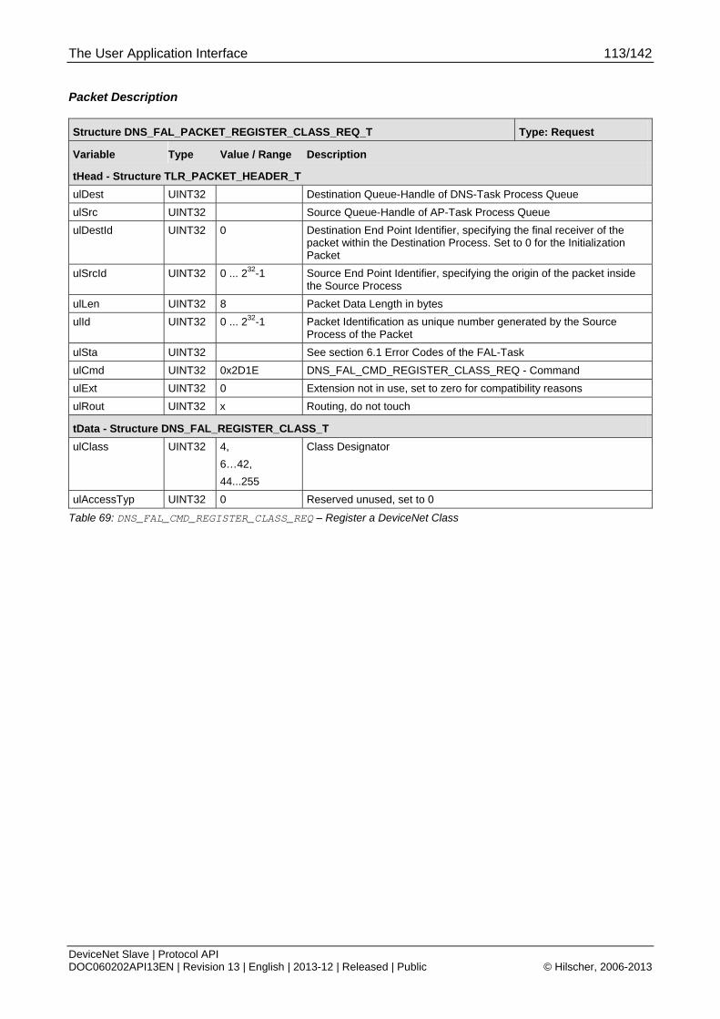
The User Application Interface 113/142
DeviceNet Slave | Protocol API DOC060202API13EN | Revision 13 | English | 2013-12 | Released | Public © Hilscher, 2006-2013
Packet Description
Structure DNS_FAL_PACKET_REGISTER_CLASS_REQ_T Type: Request
Variable Type Value / Range Description
tHead - Structure TLR_PACKET_HEADER_T
ulDest UINT32 Destination Queue-Handle of DNS-Task Process Queue
ulSrc UINT32 Source Queue-Handle of AP-Task Process Queue
ulDestId UINT32 0 Destination End Point Identifier, specifying the final receiver of the packet within the Destination Process. Set to 0 for the Initialization Packet
ulSrcId UINT32 0 ... 232-1 Source End Point Identifier, specifying the origin of the packet inside the Source Process
ulLen UINT32 8 Packet Data Length in bytes
ulId UINT32 0 ... 232-1 Packet Identification as unique number generated by the Source Process of the Packet
ulSta UINT32 See section 6.1 Error Codes of the FAL-Task
ulCmd UINT32 0x2D1E DNS_FAL_CMD_REGISTER_CLASS_REQ - Command
ulExt UINT32 0 Extension not in use, set to zero for compatibility reasons
ulRout UINT32 x Routing, do not touch
tData - Structure DNS_FAL_REGISTER_CLASS_T
ulClass UINT32 4,
6…42,
44...255
Class Designator
ulAccessTyp UINT32 0 Reserved unused, set to 0
Table 69: DNS_FAL_CMD_REGISTER_CLASS_REQ – Register a DeviceNet Class
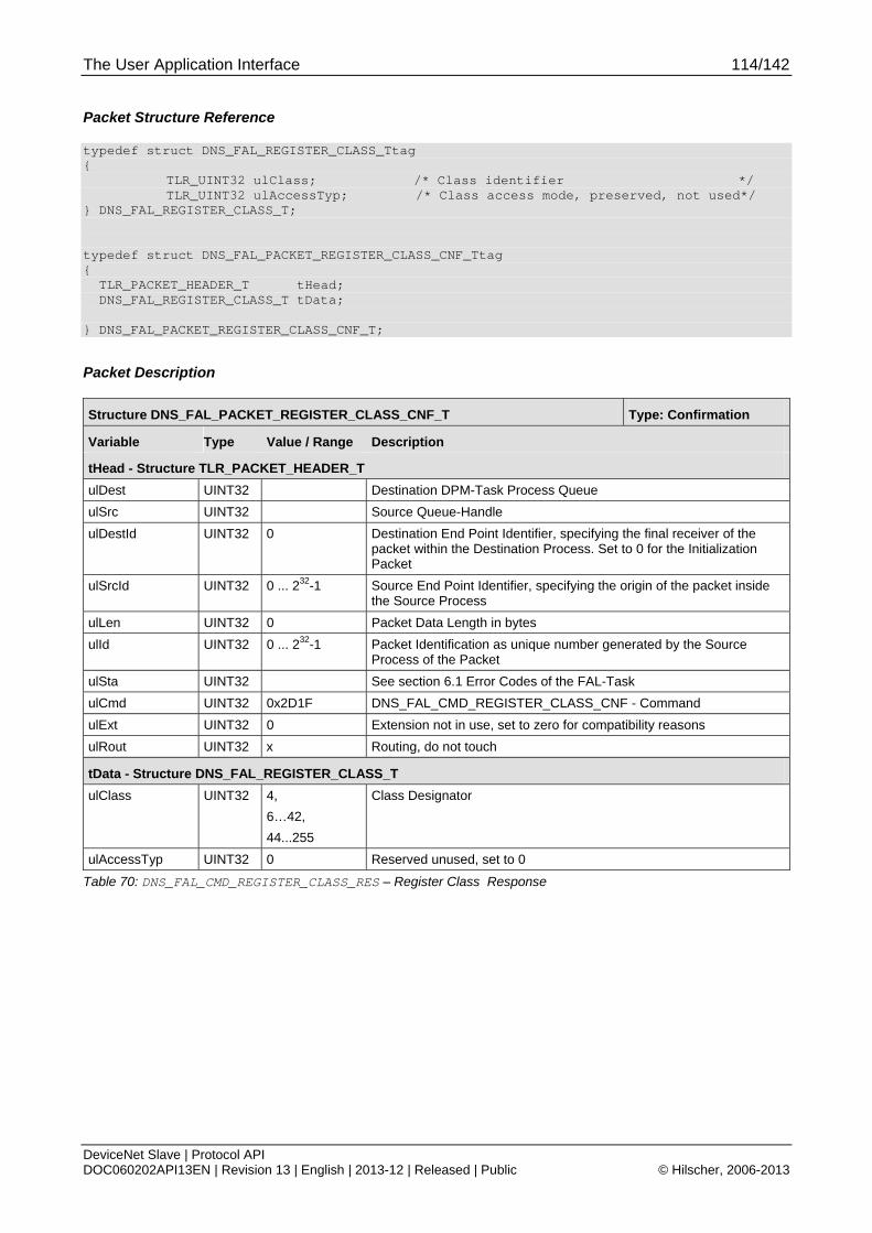
The User Application Interface 114/142
DeviceNet Slave | Protocol API DOC060202API13EN | Revision 13 | English | 2013-12 | Released | Public © Hilscher, 2006-2013
Packet Structure Reference
typedef struct DNS_FAL_REGISTER_CLASS_Ttag { TLR_UINT32 ulClass; /* Class identifier */ TLR_UINT32 ulAccessTyp; /* Class access mode, preserved, not used*/ } DNS_FAL_REGISTER_CLASS_T; typedef struct DNS_FAL_PACKET_REGISTER_CLASS_CNF_Ttag { TLR_PACKET_HEADER_T tHead; DNS_FAL_REGISTER_CLASS_T tData; } DNS_FAL_PACKET_REGISTER_CLASS_CNF_T;
Packet Description
Structure DNS_FAL_PACKET_REGISTER_CLASS_CNF_T Type: Confirmation
Variable Type Value / Range Description
tHead - Structure TLR_PACKET_HEADER_T
ulDest UINT32 Destination DPM-Task Process Queue
ulSrc UINT32 Source Queue-Handle
ulDestId UINT32 0 Destination End Point Identifier, specifying the final receiver of the packet within the Destination Process. Set to 0 for the Initialization Packet
ulSrcId UINT32 0 ... 232-1 Source End Point Identifier, specifying the origin of the packet inside the Source Process
ulLen UINT32 0 Packet Data Length in bytes
ulId UINT32 0 ... 232-1 Packet Identification as unique number generated by the Source Process of the Packet
ulSta UINT32 See section 6.1 Error Codes of the FAL-Task
ulCmd UINT32 0x2D1F DNS_FAL_CMD_REGISTER_CLASS_CNF - Command
ulExt UINT32 0 Extension not in use, set to zero for compatibility reasons
ulRout UINT32 x Routing, do not touch
tData - Structure DNS_FAL_REGISTER_CLASS_T
ulClass UINT32 4,
6…42,
44...255
Class Designator
ulAccessTyp UINT32 0 Reserved unused, set to 0
Table 70: DNS_FAL_CMD_REGISTER_CLASS_RES – Register Class Response

The User Application Interface 115/142
DeviceNet Slave | Protocol API DOC060202API13EN | Revision 13 | English | 2013-12 | Released | Public © Hilscher, 2006-2013
5.3.14 DNS_FAL_CMD_UNREGISTER_CLASS_REQ – Unregister Class
This command will unregister a previously registered class. All further requests to this class will be rejected with an error response, that this object is not existent.
Packet Structure Reference
/*********************************************/ /* DNS_FAL_CMD_UNREGISTER_CLASS_REQ Structure */ typedef struct DNS_FAL_UNREGISTER_CLASS_Ttag { TLR_UINT32 ulClass; /* Class identifier */ TLR_UINT32 ulAccessTyp; /* Instance, Class access */ } DNS_FAL_UNREGISTER_CLASS_T; #define DNS_FAL_UNREGISTER_CLASS_REQ_SIZE (sizeof(DNS_FAL_UNREGISTER_CLASS_T)) typedef struct DNS_FAL_PACKET_UNREGISTER_CLASS_REQ _Ttag { TLR_PACKET_HEADER_T tHead; DNS_FAL_UNREGISTER_CLASS_T tData; } DNS_FAL_PACKET_UNREGISTER_CLASS_REG_T;
Packet Description
Structure DNS_FAL_PACKET_UNREGISTER_CLASS_REQ_T Type: Indication
Variable Type Value / Range Description
tHead - Structure TLR_PACKET_HEADER_T
ulDest UINT32 Destination Queue-Handle of DNS-Task Process Queue
ulSrc UINT32 Source Queue-Handle of AP-Task Process Queue
ulDestId UINT32 0 Destination End Point Identifier, specifying the final receiver of the packet within the Destination Process. Set to 0 for the Initialization Packet
ulSrcId UINT32 0 ... 232-1 Source End Point Identifier, specifying the origin of the packet inside the Source Process
ulLen UINT32 8 Packet Data Length in bytes
ulId UINT32 0 ... 232-1 Packet Identification as unique number generated by the Source Process of the Packet
ulSta UINT32 See section 6.1 Error Codes of the FAL-Task
ulCmd UINT32 0x2D20 DNS_FAL_CMD_UNREGISTER_CLASS_REQ - Command
ulExt UINT32 0 Extension not in use, set to zero for compatibility reasons
ulRout UINT32 x Routing, do not touch
tData - Structure DNS_FAL_UNREGISTER_CLASS_T
ulClass UINT32 4,
6…42,
44...255
Class Designator
ulAccessTyp UINT32 0 Reserved unused, set to 0
Table 71: DNS_FAL_CMD_UNREGISTER_CLASS_REQ – Unregister a DeviceNet Class

The User Application Interface 116/142
DeviceNet Slave | Protocol API DOC060202API13EN | Revision 13 | English | 2013-12 | Released | Public © Hilscher, 2006-2013
Packet Structure Reference
/*********************************************/ /* DNS_FAL_CMD_UNREGISTER_CLASS_REQ Structure */ typedef struct DNS_FAL_UNREGISTER_CLASS_Ttag { TLR_UINT32 ulClass; /* Class identifier */ TLR_UINT32 ulAccessTyp; /* Instance, Class access */ } DNS_FAL_UNREGISTER_CLASS_T; typedef struct DNS_FAL_PACKET_UNREGISTER_CLASS_CNF_Ttag { TLR_PACKET_HEADER_T tHead; DNS_FAL_UNREGISTER_CLASS_T tData; } DNS_FAL_PACKET_UNREGISTER_CLASS_CNF_T;
Packet Description
Structure DNS_FAL_PACKET_UNREGISTER_CLASS_CNF_T Type: Confirmation
Variable Type Value / Range Description
tHead - Structure TLR_PACKET_HEADER_T
ulDest UINT32 Destination DPM-Task Process Queue
ulSrc UINT32 Source Queue-Handle
ulDestId UINT32 0 Destination End Point Identifier, specifying the final receiver of the packet within the Destination Process. Set to 0 for the Initialization Packet
ulSrcId UINT32 0 ... 232-1 Source End Point Identifier, specifying the origin of the packet inside the Source Process
ulLen UINT32 0 Packet Data Length in bytes
ulId UINT32 0 ... 232-1 Packet Identification as unique number generated by the Source Process of the Packet
ulSta UINT32 See section 6.1 Error Codes of the FAL-Task
ulCmd UINT32 0x2D21 DNS_FAL_CMD_UNREGISTER_CLASS_CNF - Response
ulExt UINT32 0 Extension not in use, set to zero for compatibility reasons
ulRout UINT32 x Routing, do not touch
tData - Structure DNS_FAL_REGISTER_CLASS_T
ulClass UINT32 4,
6…42,
44...255
Class Designator
ulAccessTyp UINT32 0 Reserved unused, set to 0
Table 72: DNS_FAL_CMD_UNREGISTER_CLASS_RES – Unregister Class Response
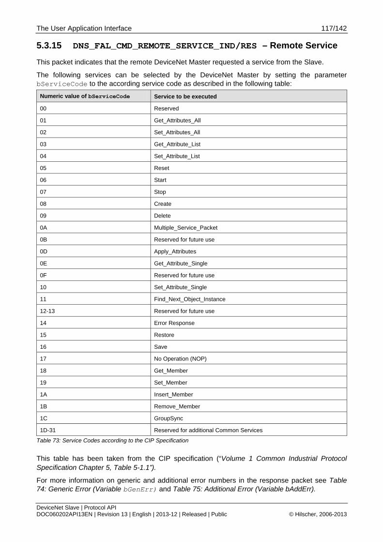
The User Application Interface 117/142
DeviceNet Slave | Protocol API DOC060202API13EN | Revision 13 | English | 2013-12 | Released | Public © Hilscher, 2006-2013
5.3.15 DNS_FAL_CMD_REMOTE_SERVICE_IND/RES – Remote Service
This packet indicates that the remote DeviceNet Master requested a service from the Slave.
The following services can be selected by the DeviceNet Master by setting the parameter bServiceCode to the according service code as described in the following table:
Numeric value of bServiceCode Service to be executed
00 Reserved
01 Get_Attributes_All
02 Set_Attributes_All
03 Get_Attribute_List
04 Set_Attribute_List
05 Reset
06 Start
07 Stop
08 Create
09 Delete
0A Multiple_Service_Packet
0B Reserved for future use
0D Apply_Attributes
0E Get_Attribute_Single
0F Reserved for future use
10 Set_Attribute_Single
11 Find_Next_Object_Instance
12-13 Reserved for future use
14 Error Response
15 Restore
16 Save
17 No Operation (NOP)
18 Get_Member
19 Set_Member
1A Insert_Member
1B Remove_Member
1C GroupSync
1D-31 Reserved for additional Common Services
Table 73: Service Codes according to the CIP Specification
This table has been taken from the CIP specification (“Volume 1 Common Industrial Protocol Specification Chapter 5, Table 5-1.1”).
For more information on generic and additional error numbers in the response packet see Table 74: Generic Error (Variable bGenErr) and Table 75: Additional Error (Variable bAddErr).
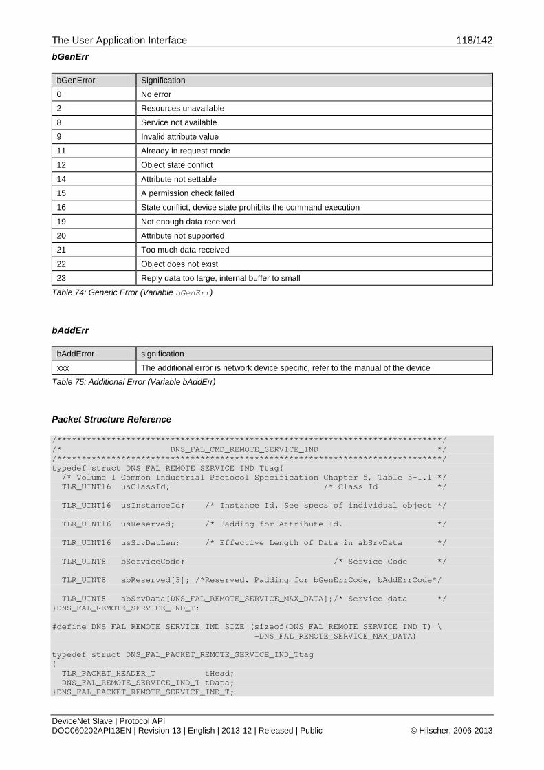
The User Application Interface 118/142
DeviceNet Slave | Protocol API DOC060202API13EN | Revision 13 | English | 2013-12 | Released | Public © Hilscher, 2006-2013
bGenErr
bGenError Signification
0 No error
2 Resources unavailable
8 Service not available
9 Invalid attribute value
11 Already in request mode
12 Object state conflict
14 Attribute not settable
15 A permission check failed
16 State conflict, device state prohibits the command execution
19 Not enough data received
20 Attribute not supported
21 Too much data received
22 Object does not exist
23 Reply data too large, internal buffer to small
Table 74: Generic Error (Variable bGenErr)
bAddErr
bAddError signification
xxx The additional error is network device specific, refer to the manual of the device
Table 75: Additional Error (Variable bAddErr)
Packet Structure Reference
/******************************************************************************/ /* DNS_FAL_CMD_REMOTE_SERVICE_IND */ /******************************************************************************/ typedef struct DNS_FAL_REMOTE_SERVICE_IND_Ttag{ /* Volume 1 Common Industrial Protocol Specification Chapter 5, Table 5-1.1 */ TLR_UINT16 usClassId; /* Class Id */ TLR_UINT16 usInstanceId; /* Instance Id. See specs of individual object */ TLR_UINT16 usReserved; /* Padding for Attribute Id. */ TLR_UINT16 usSrvDatLen; /* Effective Length of Data in abSrvData */ TLR_UINT8 bServiceCode; /* Service Code */ TLR_UINT8 abReserved[3]; /*Reserved. Padding for bGenErrCode, bAddErrCode*/ TLR_UINT8 abSrvData[DNS_FAL_REMOTE_SERVICE_MAX_DATA];/* Service data */ }DNS_FAL_REMOTE_SERVICE_IND_T; #define DNS_FAL_REMOTE_SERVICE_IND_SIZE (sizeof(DNS_FAL_REMOTE_SERVICE_IND_T) \ -DNS_FAL_REMOTE_SERVICE_MAX_DATA) typedef struct DNS_FAL_PACKET_REMOTE_SERVICE_IND_Ttag { TLR_PACKET_HEADER_T tHead; DNS_FAL_REMOTE_SERVICE_IND_T tData; }DNS_FAL_PACKET_REMOTE_SERVICE_IND_T;
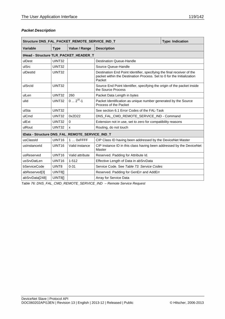
The User Application Interface 119/142
DeviceNet Slave | Protocol API DOC060202API13EN | Revision 13 | English | 2013-12 | Released | Public © Hilscher, 2006-2013
Packet Description
Structure DNS_FAL_PACKET_REMOTE_SERVICE_IND_T Type: Indication
Variable Type Value / Range Description
tHead - Structure TLR_PACKET_HEADER_T
ulDest UINT32 Destination Queue-Handle
ulSrc UINT32 Source Queue-Handle
ulDestId UINT32 Destination End Point Identifier, specifying the final receiver of the packet within the Destination Process. Set to 0 for the Initialization Packet
ulSrcId UINT32 Source End Point Identifier, specifying the origin of the packet inside the Source Process
ulLen UINT32 260 Packet Data Length in bytes
ulId UINT32 0 ... 232-1 Packet Identification as unique number generated by the Source Process of the Packet
ulSta UINT32 See section 6.1 Error Codes of the FAL-Task
ulCmd UINT32 0x2D22 DNS_FAL_CMD_REMOTE_SERVICE_IND - Command
ulExt UINT32 0 Extension not in use, set to zero for compatibility reasons
ulRout UINT32 x Routing, do not touch
tData - Structure DNS_FAL_REMOTE_SERVICE_IND_T
usClassId UINT16 1 … 0xFFFF CIP Class ID having been addressed by the DeviceNet Master
usInstanceId UINT16 Valid instance CIP Instance ID in this class having been addressed by the DeviceNet Master
usReserved UINT16 Valid attribute Reserved. Padding for Attribute Id.
usSrvDatLen UINT16 1-512 Effective Length of Data in abSrvData
bServiceCode UINT8 0-31 Service Code. See Table 73: Service Codes
abReserved[3] UINT8[] Reserved. Padding for GenErr and AddErr
abSrvData[248] UINT8[] Array for Service Data
Table 76: DNS_FAL_CMD_REMOTE_SERVICE_IND – Remote Service Request
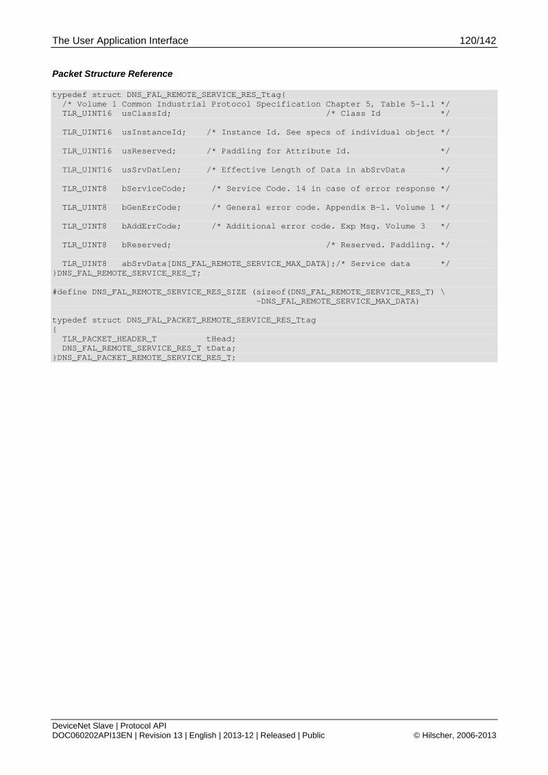
The User Application Interface 120/142
DeviceNet Slave | Protocol API DOC060202API13EN | Revision 13 | English | 2013-12 | Released | Public © Hilscher, 2006-2013
Packet Structure Reference
typedef struct DNS_FAL_REMOTE_SERVICE_RES_Ttag{ /* Volume 1 Common Industrial Protocol Specification Chapter 5, Table 5-1.1 */ TLR_UINT16 usClassId; /* Class Id */ TLR_UINT16 usInstanceId; /* Instance Id. See specs of individual object */ TLR_UINT16 usReserved; /* Paddling for Attribute Id. */ TLR_UINT16 usSrvDatLen; /* Effective Length of Data in abSrvData */ TLR_UINT8 bServiceCode; /* Service Code. 14 in case of error response */ TLR_UINT8 bGenErrCode; /* General error code. Appendix B-1. Volume 1 */ TLR_UINT8 bAddErrCode; /* Additional error code. Exp Msg. Volume 3 */ TLR_UINT8 bReserved; /* Reserved. Paddling. */ TLR_UINT8 abSrvData[DNS_FAL_REMOTE_SERVICE_MAX_DATA];/* Service data */ }DNS_FAL_REMOTE_SERVICE_RES_T; #define DNS_FAL_REMOTE_SERVICE_RES_SIZE (sizeof(DNS_FAL_REMOTE_SERVICE_RES_T) \ -DNS_FAL_REMOTE_SERVICE_MAX_DATA) typedef struct DNS_FAL_PACKET_REMOTE_SERVICE_RES_Ttag { TLR_PACKET_HEADER_T tHead; DNS_FAL_REMOTE_SERVICE_RES_T tData; }DNS_FAL_PACKET_REMOTE_SERVICE_RES_T;
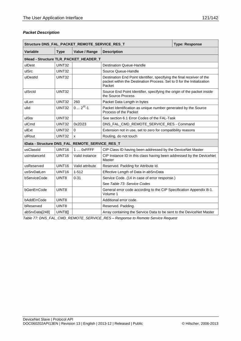
The User Application Interface 121/142
DeviceNet Slave | Protocol API DOC060202API13EN | Revision 13 | English | 2013-12 | Released | Public © Hilscher, 2006-2013
Packet Description
Structure DNS_FAL_PACKET_REMOTE_SERVICE_RES_T Type: Response
Variable Type Value / Range Description
tHead - Structure TLR_PACKET_HEADER_T
ulDest UINT32 Destination Queue-Handle
ulSrc UINT32 Source Queue-Handle
ulDestId UINT32 Destination End Point Identifier, specifying the final receiver of the packet within the Destination Process. Set to 0 for the Initialization Packet
ulSrcId UINT32 Source End Point Identifier, specifying the origin of the packet inside the Source Process
ulLen UINT32 260 Packet Data Length in bytes
ulId UINT32 0 ... 232-1 Packet Identification as unique number generated by the Source Process of the Packet
ulSta UINT32 See section 6.1 Error Codes of the FAL-Task
ulCmd UINT32 0x2D23 DNS_FAL_CMD_REMOTE_SERVICE_RES - Command
ulExt UINT32 0 Extension not in use, set to zero for compatibility reasons
ulRout UINT32 x Routing, do not touch
tData - Structure DNS_FAL_REMOTE_SERVICE_RES_T
usClassId UINT16 1 … 0xFFFF CIP Class ID having been addressed by the DeviceNet Master
usInstanceId UINT16 Valid instance CIP Instance ID in this class having been addressed by the DeviceNet Master
usReserved UINT16 Valid attribute Reserved. Padding for Attribute Id.
usSrvDatLen UINT16 1-512 Effective Length of Data in abSrvData
bServiceCode UINT8 0-31 Service Code. (14 in case of error response.)
See Table 73: Service Codes
bGenErrCode UINT8 General error code according to the CIP Specification Appendix B-1. Volume 1
bAddErrCode UINT8 Additional error code.
bReserved UINT8 Reserved. Padding.
abSrvData[248] UINT8[] Array containing the Service Data to be sent to the DeviceNet Master
Table 77: DNS_FAL_CMD_REMOTE_SERVICE_RES – Response to Remote Service Request
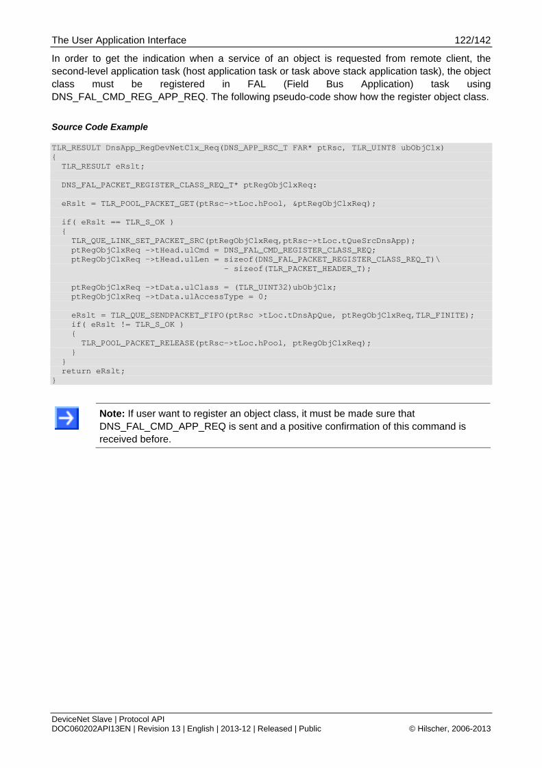
The User Application Interface 122/142
DeviceNet Slave | Protocol API DOC060202API13EN | Revision 13 | English | 2013-12 | Released | Public © Hilscher, 2006-2013
In order to get the indication when a service of an object is requested from remote client, the second-level application task (host application task or task above stack application task), the object class must be registered in FAL (Field Bus Application) task using DNS_FAL_CMD_REG_APP_REQ. The following pseudo-code show how the register object class.
Source Code Example
TLR_RESULT DnsApp_RegDevNetClx_Req(DNS_APP_RSC_T FAR* ptRsc, TLR_UINT8 ubObjClx) { TLR_RESULT eRslt; DNS_FAL_PACKET_REGISTER_CLASS_REQ_T* ptRegObjClxReq: eRslt = TLR_POOL_PACKET_GET(ptRsc->tLoc.hPool, &ptRegObjClxReq); if( eRslt == TLR_S_OK ) { TLR_QUE_LINK_SET_PACKET_SRC(ptRegObjClxReq,ptRsc->tLoc.tQueSrcDnsApp); ptRegObjClxReq ->tHead.ulCmd = DNS_FAL_CMD_REGISTER_CLASS_REQ; ptRegObjClxReq ->tHead.ulLen = sizeof(DNS_FAL_PACKET_REGISTER_CLASS_REQ_T)\ - sizeof(TLR_PACKET_HEADER_T); ptRegObjClxReq ->tData.ulClass = (TLR_UINT32)ubObjClx; ptRegObjClxReq ->tData.ulAccessType = 0; eRslt = TLR_QUE_SENDPACKET_FIFO(ptRsc >tLoc.tDnsApQue, ptRegObjClxReq,TLR_FINITE); if( eRslt != TLR_S_OK ) { TLR_POOL_PACKET_RELEASE(ptRsc->tLoc.hPool, ptRegObjClxReq); } } return eRslt; }
Note: If user want to register an object class, it must be made sure that DNS_FAL_CMD_APP_REQ is sent and a positive confirmation of this command is received before.
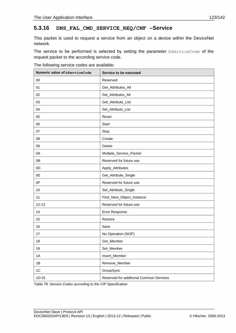
The User Application Interface 123/142
DeviceNet Slave | Protocol API DOC060202API13EN | Revision 13 | English | 2013-12 | Released | Public © Hilscher, 2006-2013
5.3.16 DNS_FAL_CMD_SERVICE_REQ/CNF –Service
This packet is used to request a service from an object on a device within the DeviceNet network.
The service to be performed is selected by setting the parameter bServiceCode of the request packet to the according service code.
The following service codes are available:
Numeric value of bServiceCode Service to be executed
00 Reserved
01 Get_Attributes_All
02 Set_Attributes_All
03 Get_Attribute_List
04 Set_Attribute_List
05 Reset
06 Start
07 Stop
08 Create
09 Delete
0A Multiple_Service_Packet
0B Reserved for future use
0D Apply_Attributes
0E Get_Attribute_Single
0F Reserved for future use
10 Set_Attribute_Single
11 Find_Next_Object_Instance
12-13 Reserved for future use
14 Error Response
15 Restore
16 Save
17 No Operation (NOP)
18 Get_Member
19 Set_Member
1A Insert_Member
1B Remove_Member
1C GroupSync
1D-31 Reserved for additional Common Services
Table 78: Service Codes according to the CIP Specification
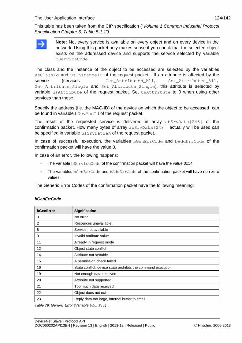
The User Application Interface 124/142
DeviceNet Slave | Protocol API DOC060202API13EN | Revision 13 | English | 2013-12 | Released | Public © Hilscher, 2006-2013
This table has been taken from the CIP specification (“Volume 1 Common Industrial Protocol Specification Chapter 5, Table 5-1.1”).
Note: Not every service is available on every object and on every device in the network. Using this packet only makes sense if you check that the selected object exists on the addressed device and supports the service selected by variable bServiceCode.
The class and the instance of the object to be accessed are selected by the variables usClassId and usInstanceID of the request packet . If an attribute is affected by the service (services Get_Attributes_All, Set_Attributes_All, Get_Attribute_Single and Set_Attribute_Single), this attribute is selected by variable usAttribute of the request packet. Set usAttribute to 0 when using other services than these.
Specify the address (i.e. the MAC-ID) of the device on which the object to be accessed can be found in variable bDevMacId of the request packet.
The result of the requested service is delivered in array abSrvData[248] of the confirmation packet. How many bytes of array abSrvData[248] actually will be used can be specified in variable usSrvDatLen of the request packet.
In case of successful execution, the variables bGenErrCode and bAddErrCode of the confirmation packet will have the value 0.
In case of an error, the following happens:
The variable bServiceCode of the confirmation packet will have the value 0x14.
The variables bGenErrCode and bAddErrCode of the confirmation packet will have non-zero
values.
The Generic Error Codes of the confirmation packet have the following meaning:
bGenErrCode
bGenError Signification
0 No error
2 Resources unavailable
8 Service not available
9 Invalid attribute value
11 Already in request mode
12 Object state conflict
14 Attribute not settable
15 A permission check failed
16 State conflict, device state prohibits the command execution
19 Not enough data received
20 Attribute not supported
21 Too much data received
22 Object does not exist
23 Reply data too large, internal buffer to small
Table 79: Generic Error (Variable bGenErr)
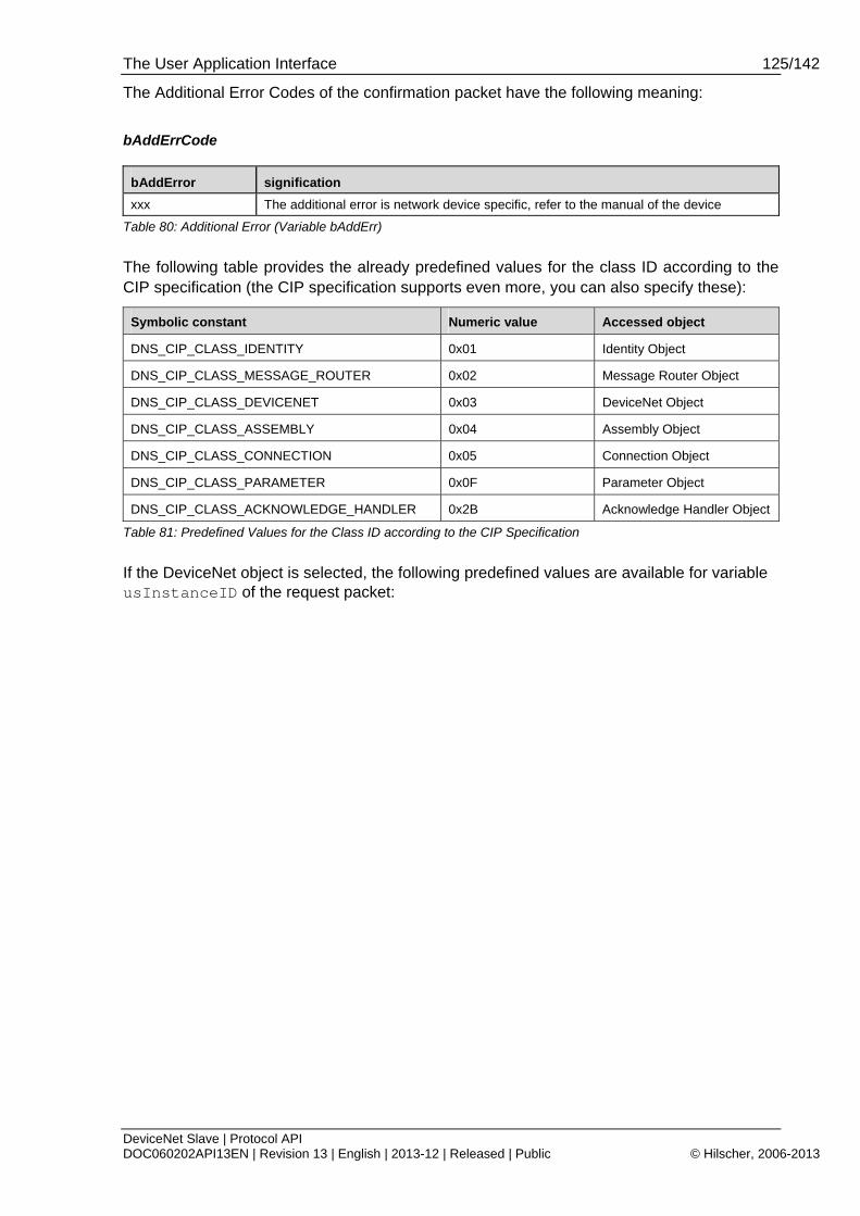
The User Application Interface 125/142
DeviceNet Slave | Protocol API DOC060202API13EN | Revision 13 | English | 2013-12 | Released | Public © Hilscher, 2006-2013
The Additional Error Codes of the confirmation packet have the following meaning:
bAddErrCode
bAddError signification
xxx The additional error is network device specific, refer to the manual of the device
Table 80: Additional Error (Variable bAddErr)
The following table provides the already predefined values for the class ID according to the CIP specification (the CIP specification supports even more, you can also specify these):
Symbolic constant Numeric value Accessed object
DNS_CIP_CLASS_IDENTITY 0x01 Identity Object
DNS_CIP_CLASS_MESSAGE_ROUTER 0x02 Message Router Object
DNS_CIP_CLASS_DEVICENET 0x03 DeviceNet Object
DNS_CIP_CLASS_ASSEMBLY 0x04 Assembly Object
DNS_CIP_CLASS_CONNECTION 0x05 Connection Object
DNS_CIP_CLASS_PARAMETER 0x0F Parameter Object
DNS_CIP_CLASS_ACKNOWLEDGE_HANDLER 0x2B Acknowledge Handler Object
Table 81: Predefined Values for the Class ID according to the CIP Specification
If the DeviceNet object is selected, the following predefined values are available for variable usInstanceID of the request packet:
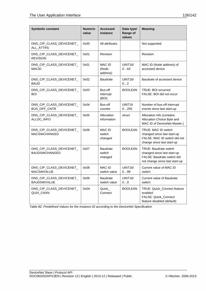
The User Application Interface 126/142
DeviceNet Slave | Protocol API DOC060202API13EN | Revision 13 | English | 2013-12 | Released | Public © Hilscher, 2006-2013
Symbolic constant Numeric value
Accessed instance
Data type/ Range of values
Meaning
DNS_CIP_CLASS_DEVICENET_ALL_ATTRS
0x00 All attributes Not supported
DNS_CIP_CLASS_DEVICENET_REVISION
0x01 Revision Revision
DNS_CIP_CLASS_DEVICENET_MACID
0x01 MAC ID (Node address)
UINT16/ 0…63
MAC ID (Node address) of accessed device
DNS_CIP_CLASS_DEVICENET_BAUD
0x02 Baudrate UINT16/ 0…2
Baudrate of accessed device
DNS_CIP_CLASS_DEVICENET_BOI
0x03 Bus-off interrupt (BOI)
BOOLEAN TRUE: BOI occurred FALSE: BOI did not occur
DNS_CIP_CLASS_DEVICENET_BUS_OFF_CNTR
0x04 Bus-off counter
UINT16 0…255
Number of bus-off interrupt events since last start-up
DNS_CIP_CLASS_DEVICENET_ALLOC_INFO
0x05 Allocation information
struct Allocation info (contains Allocation Choice Byte and MAC ID of DeviceNet Master.)
DNS_CIP_CLASS_DEVICENET_MACSWCHANGED
0x06 MAC ID switch changed
BOOLEAN TRUE: MAC ID switch changed since last start-up FALSE: MAC ID switch did not change since last start-up
DNS_CIP_CLASS_DEVICENET_BAUDSWCHANGED
0x07 Baudrate switch changed
BOOLEAN TRUE: Baudrate switch changed since last start-up FALSE: Baudrate switch did not change since last start-up
DNS_CIP_CLASS_DEVICENET_MACSWVALUE
0x08 MAC ID switch value
UINT16/ 0…99
Current value of MAC ID switch
DNS_CIP_CLASS_DEVICENET_BAUDSWVALUE
0x09 Baudrate switch value
UINT16/ 0…9
Current value of Baudrate switch
DNS_CIP_CLASS_DEVICENET_QUIX_CNXN
0x0A Quick_ Connect
BOOLEAN TRUE: Quick_Connect feature enabled FALSE: Quick_Connect feature disabled (default)
Table 82: Predefined Values for the Instance ID according to the DeviceNet Specification

The User Application Interface 127/142
DeviceNet Slave | Protocol API DOC060202API13EN | Revision 13 | English | 2013-12 | Released | Public © Hilscher, 2006-2013
Packet Structure Reference
/******************************************************************************/ /* DNS_FAL_CMD_SERVICE_REQ */ /******************************************************************************/ typedef struct DNS_FAL_SERVICE_IND_Ttag{ /* Volume 1 Common Industrial Protocol Specification Chapter 5, Table 5-1.1 */ TLR_UINT16 usClassId; /* Class Id */ TLR_UINT16 usInstanceId; /* Instance Id. See specs of individual object */ TLR_UINT16 usAttribute; /* Attribute Id for get/set attr only */ TLR_UINT16 usSrvDatLen; /* Effective Length of Data in abSrvData */ /* 00=Reserved 01=Get_Attributes_All 02=Set_Attributes_All 03=Get_Attribute_List 04=Set_Attribute_List 05=Reset 06=Start 07=Stop 08=Create 09=Delete 0A=Multiple_Service_Packet 0B=Reserved for future use 0D=Apply_Attributes 0E=Get_Attribute_Single 0F=Reserved for future use 10=Set_Attribute_Single 11=Find_Next_Object_Instance 12-13=Reserved for future use 14=ror Response (used by DevNet only) 15=Restore 16=Save 17=No Operation(NOP) 18=Get_Member 19=Set_Member 1A=Insert_Member 1B=Remove_Member 1C=GroupSync 1D-31 = Reserved for additional Common Services */ TLR_UINT8 bServiceCode; /* Service Code */ TLR_UINT8 abReserved[2]; /*Reserved. Padding for bGenErrCode, bAddErrCode*/ TLR_UINT8 bDevMacId; /* Device mac address where to send the servive */ TLR_UINT8 abSrvData[DNS_FAL_REMOTE_SERVICE_MAX_DATA];/* Service data */ }DNS_FAL_SERVICE_REQ_T; #define DNS_FAL_SERVICE_REQ_SIZE (sizeof(DNS_FAL_SERVICE_REQ_T) \ -DNS_FAL_REMOTE_SERVICE_MAX_DATA) typedef struct DNS_FAL_PACKET_SERVICE_REQ_Ttag { TLR_PACKET_HEADER_T tHead; DNS_FAL_SERVICE_REQ_T tData; }DNS_FAL_PACKET_SERVICE_REQ_T;
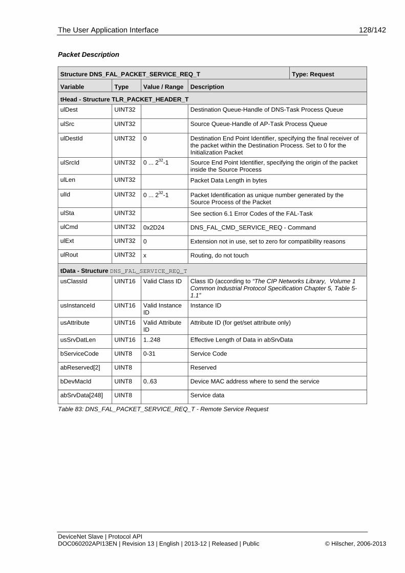
The User Application Interface 128/142
DeviceNet Slave | Protocol API DOC060202API13EN | Revision 13 | English | 2013-12 | Released | Public © Hilscher, 2006-2013
Packet Description
Structure DNS_FAL_PACKET_SERVICE_REQ_T Type: Request
Variable Type Value / Range Description
tHead - Structure TLR_PACKET_HEADER_T
ulDest UINT32 Destination Queue-Handle of DNS-Task Process Queue
ulSrc UINT32 Source Queue-Handle of AP-Task Process Queue
ulDestId UINT32 0 Destination End Point Identifier, specifying the final receiver of the packet within the Destination Process. Set to 0 for the Initialization Packet
ulSrcId UINT32 0 ... 232-1 Source End Point Identifier, specifying the origin of the packet inside the Source Process
ulLen UINT32 Packet Data Length in bytes
ulId UINT32 0 ... 232-1 Packet Identification as unique number generated by the Source Process of the Packet
ulSta UINT32 See section 6.1 Error Codes of the FAL-Task
ulCmd UINT32 0x2D24 DNS_FAL_CMD_SERVICE_REQ - Command
ulExt UINT32 0 Extension not in use, set to zero for compatibility reasons
ulRout UINT32 x Routing, do not touch
tData - Structure DNS_FAL_SERVICE_REQ_T
usClassId UINT16 Valid Class ID Class ID (according to “The CIP Networks Library, Volume 1 Common Industrial Protocol Specification Chapter 5, Table 5-1.1”
usInstanceId UINT16 Valid Instance ID
Instance ID
usAttribute UINT16 Valid Attribute ID
Attribute ID (for get/set attribute only)
usSrvDatLen UINT16 1..248 Effective Length of Data in abSrvData
bServiceCode UINT8 0-31 Service Code
abReserved[2] UINT8 Reserved
bDevMacId UINT8 0..63 Device MAC address where to send the service
abSrvData[248] UINT8 Service data
Table 83: DNS_FAL_PACKET_SERVICE_REQ_T - Remote Service Request
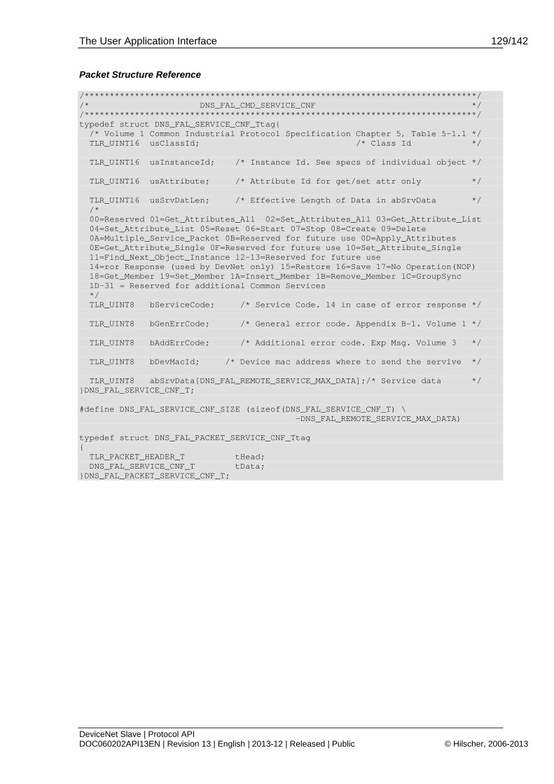
The User Application Interface 129/142
DeviceNet Slave | Protocol API DOC060202API13EN | Revision 13 | English | 2013-12 | Released | Public © Hilscher, 2006-2013
Packet Structure Reference
/******************************************************************************/ /* DNS_FAL_CMD_SERVICE_CNF */ /******************************************************************************/ typedef struct DNS_FAL_SERVICE_CNF_Ttag{ /* Volume 1 Common Industrial Protocol Specification Chapter 5, Table 5-1.1 */ TLR_UINT16 usClassId; /* Class Id */ TLR_UINT16 usInstanceId; /* Instance Id. See specs of individual object */ TLR_UINT16 usAttribute; /* Attribute Id for get/set attr only */ TLR_UINT16 usSrvDatLen; /* Effective Length of Data in abSrvData */ /* 00=Reserved 01=Get_Attributes_All 02=Set_Attributes_All 03=Get_Attribute_List 04=Set_Attribute_List 05=Reset 06=Start 07=Stop 08=Create 09=Delete 0A=Multiple_Service_Packet 0B=Reserved for future use 0D=Apply_Attributes 0E=Get_Attribute_Single 0F=Reserved for future use 10=Set_Attribute_Single 11=Find_Next_Object_Instance 12-13=Reserved for future use 14=ror Response (used by DevNet only) 15=Restore 16=Save 17=No Operation(NOP) 18=Get_Member 19=Set_Member 1A=Insert_Member 1B=Remove_Member 1C=GroupSync 1D-31 = Reserved for additional Common Services */ TLR_UINT8 bServiceCode; /* Service Code. 14 in case of error response */ TLR_UINT8 bGenErrCode; /* General error code. Appendix B-1. Volume 1 */ TLR_UINT8 bAddErrCode; /* Additional error code. Exp Msg. Volume 3 */ TLR_UINT8 bDevMacId; /* Device mac address where to send the servive */ TLR_UINT8 abSrvData[DNS_FAL_REMOTE_SERVICE_MAX_DATA];/* Service data */ }DNS_FAL_SERVICE_CNF_T; #define DNS_FAL_SERVICE_CNF_SIZE (sizeof(DNS_FAL_SERVICE_CNF_T) \ -DNS_FAL_REMOTE_SERVICE_MAX_DATA) typedef struct DNS_FAL_PACKET_SERVICE_CNF_Ttag { TLR_PACKET_HEADER_T tHead; DNS_FAL_SERVICE_CNF_T tData; }DNS_FAL_PACKET_SERVICE_CNF_T;
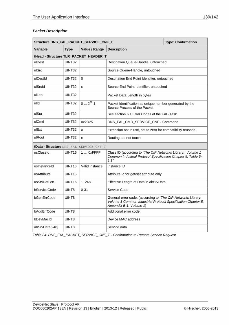
The User Application Interface 130/142
DeviceNet Slave | Protocol API DOC060202API13EN | Revision 13 | English | 2013-12 | Released | Public © Hilscher, 2006-2013
Packet Description
Structure DNS_FAL_PACKET_SERVICE_CNF_T Type: Confirmation
Variable Type Value / Range Description
tHead - Structure TLR_PACKET_HEADER_T
ulDest UINT32 Destination Queue-Handle, untouched
ulSrc UINT32 Source Queue-Handle, untouched
ulDestId UINT32 0 Destination End Point Identifier, untouched
ulSrcId UINT32 x Source End Point Identifier, untouched
ulLen UINT32 Packet Data Length in bytes
ulId UINT32 0 ... 232-1 Packet Identification as unique number generated by the Source Process of the Packet
ulSta UINT32 See section 6.1 Error Codes of the FAL-Task
ulCmd UINT32 0x2D25 DNS_FAL_CMD_SERVICE_CNF - Command
ulExt UINT32 0 Extension not in use, set to zero for compatibility reasons
ulRout UINT32 x Routing, do not touch
tData - Structure DNS_FAL_SERVICE_CNF_T
usClassId UINT16 1 … 0xFFFF Class ID (according to “The CIP Networks Library, Volume 1 Common Industrial Protocol Specification Chapter 5, Table 5-1.1”
usInstanceId UINT16 Valid instance Instance ID
usAttribute UINT16 Attribute Id for get/set attribute only
usSrvDatLen UINT16 1..248 Effective Length of Data in abSrvData
bServiceCode UINT8 0-31 Service Code
bGenErrCode UINT8 General error code. (according to “The CIP Networks Library, Volume 1 Common Industrial Protocol Specification Chapter 5, Appendix B-1. Volume 1)
bAddErrCode UINT8 Additional error code.
bDevMacId UINT8 Device MAC address
abSrvData[248] UINT8 Service data
Table 84: DNS_FAL_PACKET_SERVICE_CNF_T - Confirmation to Remote Service Request
The User Application Interface 131/142
DeviceNet Slave | Protocol API DOC060202API13EN | Revision 13 | English | 2013-12 | Released | Public © Hilscher, 2006-2013
5.4 Hardware Switches for the Adjustment of Slave Address and Baudrate
For handling address and baud rate switches on a netX device, the firmware must be enabled to evaluate the switch values from the hardware. This can be done by setting a special TAG via the “Tag List Editor” tool. In this case, the values which are configured via database or packet interface will be ignored.
If the hardware switch function is not enabled via TAG, then the firmware uses the values set either via NXD or IniBatch database or via packet interface (SET_CONFIGURATION_REQ or RCX_SET_HW_SWITCH_VALUE_REQ)
(See section 5.4.1 “RCX_SET_HW_SWITCH_VALUES_REQ/CNF – Set the values of the Hardware Switch”).
Enabling and disabling Address and Baudrate Switching
On database files and SET_CONFIGURATION_REQ evaluating the switches can be activated or deactivated. This information is located at the SystemFlags
MSK_DNS_SYS_FLG_ADR_SW_ENABLE = 0x10
MSK_DNS_SYS_FLG_BAUD_SW_ENABLE = 0x20.
Also see section 5.2.2 “DNS_AP_CMD_SET_CONFIGURATION_REQ/CNF – Set Configuration”.
Behavior at Start-up
In general, the firmware stack can be configured in different ways. Only one type of configuration can be active at a certain time. These are evaluated at start-up in the following order:
SYCON.net database
iniBatch database (via netX Configuration Tool)
Warmstart Request packet (compatibility)
Set Configuration Request packet
After a Restart the stack will first search for the SYCON.net database files (config.nxd). If these are found all other configuration methods will not be accepted. If no SYCON.net database exists, but an iniBatch database exists, its configuration will be used and configuration packets will be not accepted.
If no database is found the stack is unconfigured until the receipt of the first configuration packet. In this case the firmware waits for the SET_CONFIGURATION_REQ or WARMSTART_REQ packet. Once one of these packets (i.e. SET_CONFIGURATION_REQ) was received, the other one (i.e WARMSTART_REQ) will be rejected.
The host has the possibility to modify the configuration with the packet RCX_SET_HW_SWITCH_VALUE_REQ
Using the hardware switches for adjusting of slave address and baudrate requires the option Application_controlled being active (either when configuring using SET_CONFIGURATION_REQ packet (see DNS_AP_CMD_SET_CONFIGURATION_REQ/CNF – Set Configuration on page 58) or in the SYCON.net database file config.nxd).
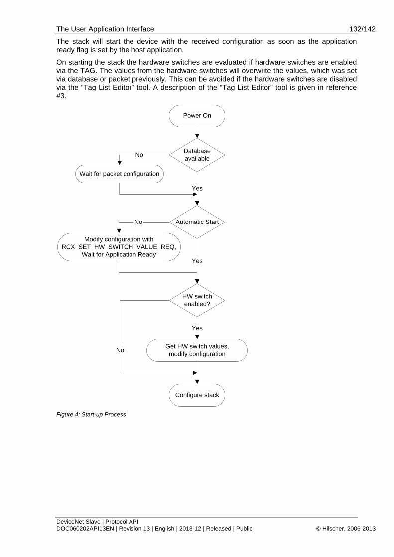
The User Application Interface 132/142
DeviceNet Slave | Protocol API DOC060202API13EN | Revision 13 | English | 2013-12 | Released | Public © Hilscher, 2006-2013
The stack will start the device with the received configuration as soon as the application ready flag is set by the host application.
On starting the stack the hardware switches are evaluated if hardware switches are enabled via the TAG. The values from the hardware switches will overwrite the values, which was set via database or packet previously. This can be avoided if the hardware switches are disabled via the “Tag List Editor” tool. A description of the “Tag List Editor” tool is given in reference #3.
Databaseavailable
Power On
Wait for packet configuration
Automatic Start
No
Yes
HW switchenabled?
Get HW switch values,modify configuration
Configure stack
Yes
Yes
No
Modify configuration withRCX_SET_HW_SWITCH_VALUE_REQ,
Wait for Application Ready
No
Figure 4: Start-up Process

The User Application Interface 133/142
DeviceNet Slave | Protocol API DOC060202API13EN | Revision 13 | English | 2013-12 | Released | Public © Hilscher, 2006-2013
5.4.1 RCX_SET_HW_SWITCH_VALUES_REQ/CNF – Set the values of the Hardware Switch
If the Host application needs to change or set the hardware switch value, the RCX_SET_HW_SWITCH_VALUES_REQ packet shall be used to transmit the values to the stack. These values can be a new station address or a new baud rate setting, for instance. In this case it is necessary that the device has already received a default configuration and is waiting for application ready or BUS_ON signal. As soon application ready is set by the host application the device starts with the last received parameters. This means that the hardware switch values shall be set before the application ready is set.
The data area of the packet contains:
the number of switches to service (variable ulNumberOfSwitches)
and as many structures of type TLR_SWITCH_VALUE_T describing a single switch as
corresponds to the number of switches (i.e. the content of variable ulNumberOfSwitches):
The structure contains a string uniquely identifying the described switch and the switch value, i.e. the value set on the respective hardware switch
It looks like:
structure tSwitchValue (Type TLR_SWITCH_VALUE_T)
Variable Type Value / Range
Description
abSwitchName UINT8[16] char Switch Name Identifier string. Max. 16 characters
ulValue UINT32 0 ... 232 -1 Switch value
Table 85: tSwitchValue – Structure of Switch Value set
Initialization behavior:
At the CHANNEL_INIT the stack shall store the value of the hardware switch (i.e. device address) which is set by the previous RCX_SET_HW_SWITCH_VALUES_REQ packet. Only with a SYSTEM_RESET the device address shall be reset and a configuration with a new RCX_SET_HW_SWITCH_VALUES_REQ packet shall be done. The behavior using the configuration packet SET_CONFIG_REQ is the same.
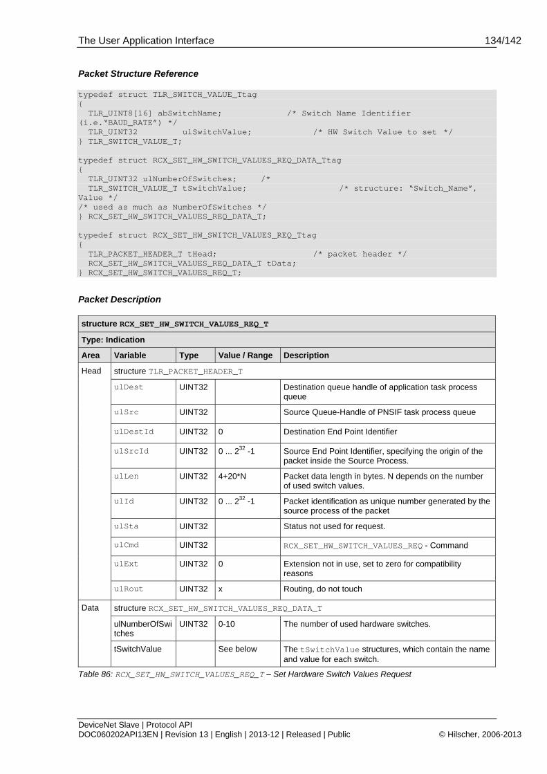
The User Application Interface 134/142
DeviceNet Slave | Protocol API DOC060202API13EN | Revision 13 | English | 2013-12 | Released | Public © Hilscher, 2006-2013
Packet Structure Reference
typedef struct TLR_SWITCH_VALUE_Ttag { TLR_UINT8[16] abSwitchName; /* Switch Name Identifier (i.e.“BAUD_RATE”) */ TLR_UINT32 ulSwitchValue; /* HW Switch Value to set */ } TLR_SWITCH_VALUE_T; typedef struct RCX_SET_HW_SWITCH_VALUES_REQ_DATA_Ttag { TLR_UINT32 ulNumberOfSwitches; /* TLR_SWITCH_VALUE_T tSwitchValue; /* structure: “Switch_Name”, Value */ /* used as much as NumberOfSwitches */ } RCX_SET_HW_SWITCH_VALUES_REQ_DATA_T; typedef struct RCX_SET_HW_SWITCH_VALUES_REQ_Ttag { TLR_PACKET_HEADER_T tHead; /* packet header */ RCX_SET_HW_SWITCH_VALUES_REQ_DATA_T tData; } RCX_SET_HW_SWITCH_VALUES_REQ_T;
Packet Description
structure RCX_SET_HW_SWITCH_VALUES_REQ_T
Type: Indication
Area Variable Type Value / Range Description
structure TLR_PACKET_HEADER_T
ulDest UINT32 Destination queue handle of application task process queue
ulSrc UINT32 Source Queue-Handle of PNSIF task process queue
ulDestId UINT32 0 Destination End Point Identifier
ulSrcId UINT32 0 ... 232 -1 Source End Point Identifier, specifying the origin of the packet inside the Source Process.
ulLen UINT32 4+20*N Packet data length in bytes. N depends on the number of used switch values.
ulId UINT32 0 ... 232 -1 Packet identification as unique number generated by the source process of the packet
ulSta UINT32 Status not used for request.
ulCmd UINT32 RCX_SET_HW_SWITCH_VALUES_REQ - Command
ulExt UINT32 0 Extension not in use, set to zero for compatibility reasons
Head
ulRout UINT32 x Routing, do not touch
structure RCX_SET_HW_SWITCH_VALUES_REQ_DATA_T
ulNumberOfSwitches
UINT32 0-10 The number of used hardware switches.
Data
tSwitchValue See below The tSwitchValue structures, which contain the name and value for each switch.
Table 86: RCX_SET_HW_SWITCH_VALUES_REQ_T – Set Hardware Switch Values Request

The User Application Interface 135/142
DeviceNet Slave | Protocol API DOC060202API13EN | Revision 13 | English | 2013-12 | Released | Public © Hilscher, 2006-2013
Packet Structure Reference
typedef struct RCX_SET_HW_SWITCH_VALUES_CNF_DATA_Ttag { } RCX_SET_HW_SWITCH_VALUES_CNF_DATA_T; typedef RCX_SET_HW_SWITCH_VALUES_CNF_Ttag { TLR_PACKET_HEADER_T tHead; /* packet header */ RCX_SET_HW_SWITCH_VALUES_CNF_DATA_T tData; /* packet data */ } RCX_SET_HW_SWITCH_VALUES_CNF_T; #define RCX_SET_HW_SWITCH_VALUES_CNF_PACKET_SIZE sizeof(RCX_SET_HW_SWITCH_VALUES_CNF_T)
Packet Description
structure RCX_SET_HW_SWITCH_VALUE_CNF_T
Type: Confirmation
Area Variable Type Value / Range Description
structure TLR_PACKET_HEADER_T
ulDest UINT32 Destination queue handle, do not touch
ulSrc UINT32 Source Queue-Handle, do not touch
ulDestId UINT32 0 Destination End Point Identifier. Not in use, set to zero for compatibility reasons.
ulSrcId UINT32 0 ... 232 -1 Source End Point Identifier, do not touch.
ulLen UINT32 0 Packet data length in bytes.
ulId UINT32 0 ... 232 -1 Packet identification, untouched
ulSta UINT32 Error code. Either TLR_S_OK or TLR_E_FAIL
ulCmd UINT32 RCX_SET_HW_SWITCH_VALUES_CNF - Command
ulExt UINT32 0 Extension, untouched
Head
ulRout UINT32 x Routing, do not touch
Table 87: RCX_SET_HW_SWITCH_VALUES_CNF – Confirmation to Set Hardware Switch Values Request
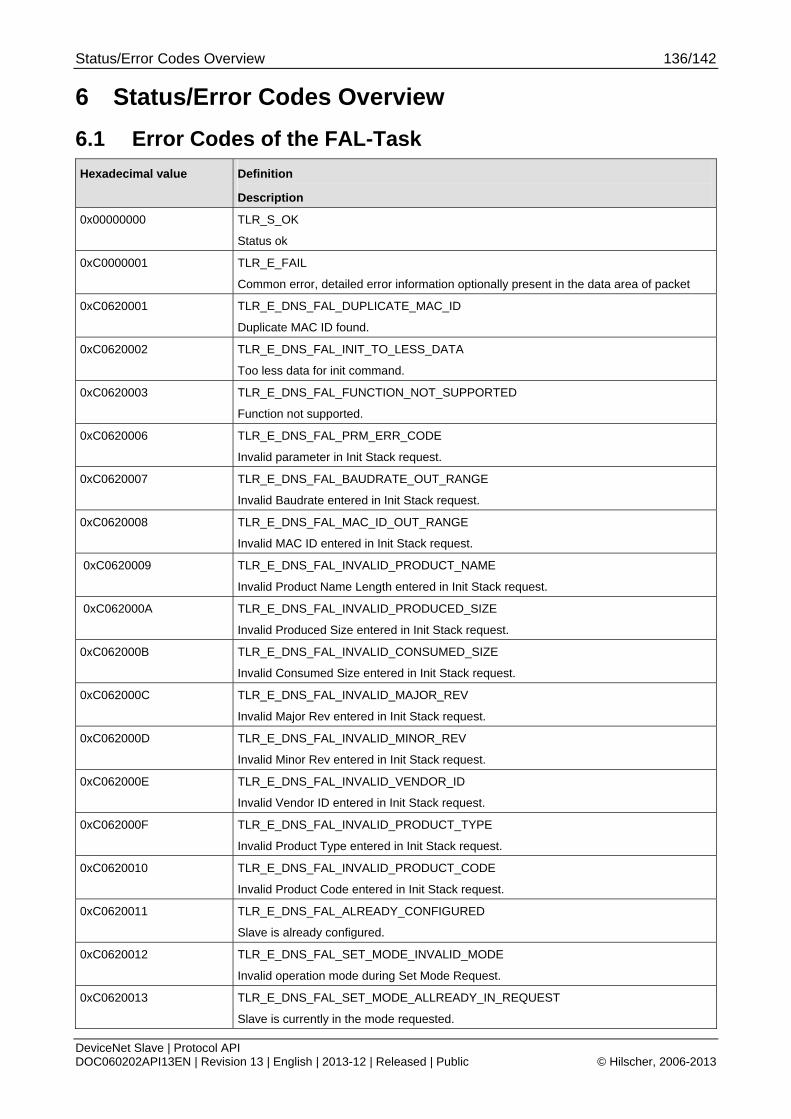
Status/Error Codes Overview 136/142
DeviceNet Slave | Protocol API DOC060202API13EN | Revision 13 | English | 2013-12 | Released | Public © Hilscher, 2006-2013
6 Status/Error Codes Overview
6.1 Error Codes of the FAL-Task
Hexadecimal value Definition
Description
0x00000000 TLR_S_OK
Status ok
0xC0000001 TLR_E_FAIL
Common error, detailed error information optionally present in the data area of packet
0xC0620001 TLR_E_DNS_FAL_DUPLICATE_MAC_ID
Duplicate MAC ID found.
0xC0620002 TLR_E_DNS_FAL_INIT_TO_LESS_DATA
Too less data for init command.
0xC0620003 TLR_E_DNS_FAL_FUNCTION_NOT_SUPPORTED
Function not supported.
0xC0620006 TLR_E_DNS_FAL_PRM_ERR_CODE
Invalid parameter in Init Stack request.
0xC0620007 TLR_E_DNS_FAL_BAUDRATE_OUT_RANGE
Invalid Baudrate entered in Init Stack request.
0xC0620008 TLR_E_DNS_FAL_MAC_ID_OUT_RANGE
Invalid MAC ID entered in Init Stack request.
0xC0620009 TLR_E_DNS_FAL_INVALID_PRODUCT_NAME
Invalid Product Name Length entered in Init Stack request.
0xC062000A TLR_E_DNS_FAL_INVALID_PRODUCED_SIZE
Invalid Produced Size entered in Init Stack request.
0xC062000B TLR_E_DNS_FAL_INVALID_CONSUMED_SIZE
Invalid Consumed Size entered in Init Stack request.
0xC062000C TLR_E_DNS_FAL_INVALID_MAJOR_REV
Invalid Major Rev entered in Init Stack request.
0xC062000D TLR_E_DNS_FAL_INVALID_MINOR_REV
Invalid Minor Rev entered in Init Stack request.
0xC062000E TLR_E_DNS_FAL_INVALID_VENDOR_ID
Invalid Vendor ID entered in Init Stack request.
0xC062000F TLR_E_DNS_FAL_INVALID_PRODUCT_TYPE
Invalid Product Type entered in Init Stack request.
0xC0620010 TLR_E_DNS_FAL_INVALID_PRODUCT_CODE
Invalid Product Code entered in Init Stack request.
0xC0620011 TLR_E_DNS_FAL_ALREADY_CONFIGURED
Slave is already configured.
0xC0620012 TLR_E_DNS_FAL_SET_MODE_INVALID_MODE
Invalid operation mode during Set Mode Request.
0xC0620013 TLR_E_DNS_FAL_SET_MODE_ALLREADY_IN_REQUEST
Slave is currently in the mode requested.

Status/Error Codes Overview 137/142
DeviceNet Slave | Protocol API DOC060202API13EN | Revision 13 | English | 2013-12 | Released | Public © Hilscher, 2006-2013
Hexadecimal value Definition
Description
0xC0620014 TLR_E_DNS_FAL_GET_STATUS_INVALID_STATUS
Reserved byte not set to zero.
0xC0620015 TLR_E_DNS_FAL_UPDATE_IO_INVALID_IN_LEN
Invalid Input Length specified in Update I/O Command.
0xC0620016 TLR_E_DNS_FAL_UPDATE_IO_INVALID_OUT_LEN
Invalid Output Length specified in Update I/O Command.
0xC0620017 TLR_E_DNS_FAL_UPDATE_IO_INVALID_OUT_OFFSET
Invalid Output Offset specified in Update I/O Command.
0xC0620018 TLR_E_DNS_FAL_UPDATE_IO_INVALID_IN_OFFSET
Invalid Input Offset specified in Update I/O Command.
0xC0620019 TLR_E_DNS_FAL_SET_INPUT_INVALID_IN_LEN
Invalid Input Length specified in Set Input Command.
0xC062001A TLR_E_DNS_FAL_SET_INPUT_INVALID_IN_OFFSET
Invalid Input Offset specified in Set Input Command.
0xC062001B TLR_E_DNS_FAL_GET_OUTPUT_INVALID_OUT_LEN
Invalid Output Length specified in Get Output Command.
0xC062001C TLR_E_DNS_FAL_GET_OUTPUT_INVALID_OUT_OFFSET
Invalid Output Offset specified in Get Output Command.
0xC062001E TLR_E_DNS_FAL_DOWNLOAD_INVALID_AREA_CODE
Invalid download area specified.
0xC062001F TLR_E_DNS_FAL_DOWNLOAD_INVALID_SEQUENCE
Invalid Download Sequence.
0xC0620020 TLR_E_DNS_FAL_DOWNLOAD_TO_MUCH_DATA
Too much data received.
0xC0620021 TLR_E_DNS_FAL_DOWNLOAD_TO_LESS_DATA
Not enough data received during the download.
0xC0620022 TLR_E_DNS_FAL_NO_CONFIGURATION
No configuration.
0xC0620023 TLR_E_DNS_FAL_BUS_OFF_STATE
Network error BUS OFF detected.
0xC0620024 TLR_E_DNS_FAL_NO_NETWORK
No network access.
0xC0620025 TLR_E_DNS_FAL_BUS_STOP
Communication not released by application (BUS Stop).
0xC0620026 TLR_E_DNS_FAL_NO_COMMUNICATION
No communication.
0xC0620027 TLR_E_DNS_FAL_SERVICE_DATA_LENGTH_INVALID
Invalid length of service data.
0xC0620028 TLR_E_DNS_FAL_USER_OBJ_CONFIGURED
User object already configured.
0xC0620029 TLR_E_DNS_FAL_USER_OBJ_LOCKED
User object is locked and cannot be passed through.
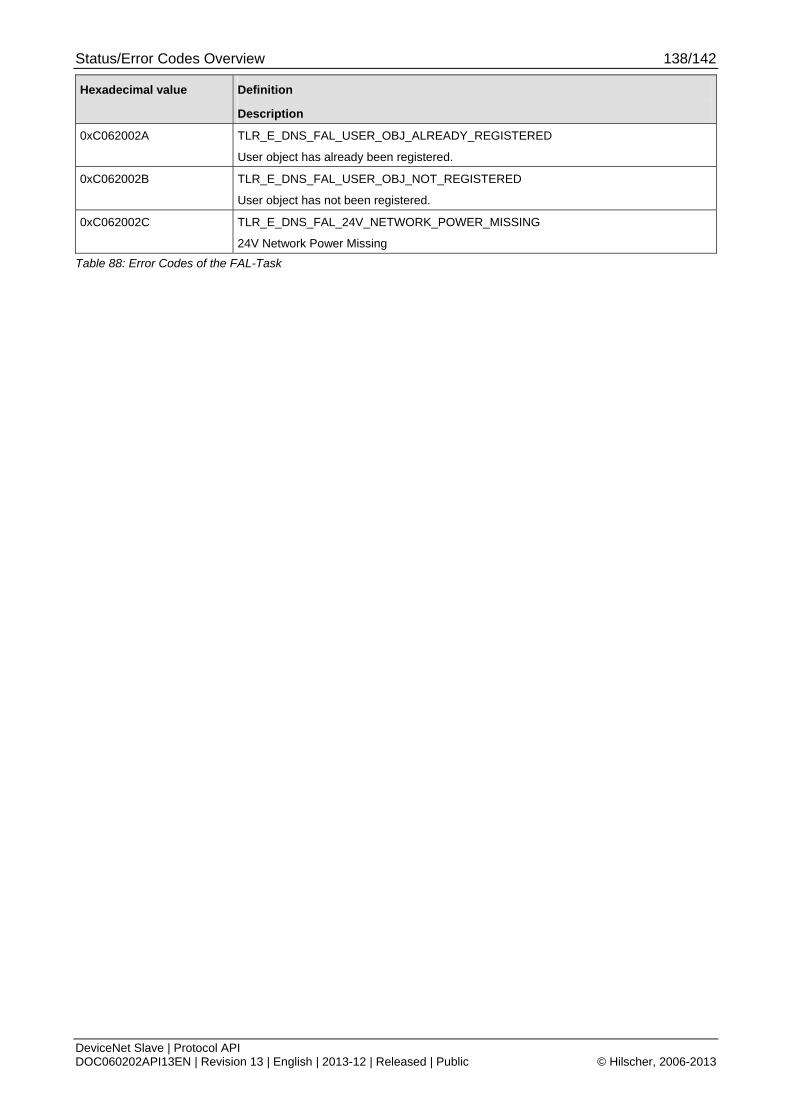
Status/Error Codes Overview 138/142
DeviceNet Slave | Protocol API DOC060202API13EN | Revision 13 | English | 2013-12 | Released | Public © Hilscher, 2006-2013
Hexadecimal value Definition
Description
0xC062002A TLR_E_DNS_FAL_USER_OBJ_ALREADY_REGISTERED
User object has already been registered.
0xC062002B TLR_E_DNS_FAL_USER_OBJ_NOT_REGISTERED
User object has not been registered.
0xC062002C TLR_E_DNS_FAL_24V_NETWORK_POWER_MISSING
24V Network Power Missing
Table 88: Error Codes of the FAL-Task
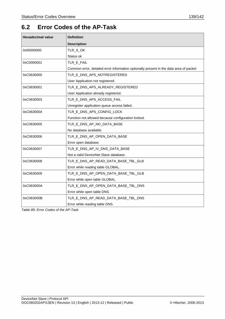
Status/Error Codes Overview 139/142
DeviceNet Slave | Protocol API DOC060202API13EN | Revision 13 | English | 2013-12 | Released | Public © Hilscher, 2006-2013
6.2 Error Codes of the AP-Task
Hexadecimal value Definition
Description
0x00000000 TLR_S_OK
Status ok
0xC0000001 TLR_E_FAIL
Common error, detailed error information optionally present in the data area of packet
0xC0630000 TLR_E_DNS_APS_NOTREGISTERED
User Application not registered.
0xC0630001 TLR_E_DNS_APS_ALREADY_REGISTERED
User Application already registered.
0xC0630003 TLR_E_DNS_APS_ACCESS_FAIL
Unregister application queue access failed.
0xC0630004 TLR_E_DNS_APS_CONFIG_LOCK
Function not allowed because configuration locked.
0xC0630005 TLR_E_DNS_AP_NO_DATA_BASE
No database available.
0xC0630006 TLR_E_DNS_AP_OPEN_DATA_BASE
Error open database.
0xC0630007 TLR_E_DNS_AP_IV_DNS_DATA_BASE
Not a valid DeviceNet Slave database.
0xC0630008 TLR_E_DNS_AP_READ_DATA_BASE_TBL_GLB
Error while reading table GLOBAL.
0xC0630009 TLR_E_DNS_AP_OPEN_DATA_BASE_TBL_GLB
Error while open table GLOBAL.
0xC063000A TLR_E_DNS_AP_OPEN_DATA_BASE_TBL_DNS
Error while open table DNS.
0xC063000B TLR_E_DNS_AP_READ_DATA_BASE_TBL_DNS
Error while reading table DNS.
Table 89: Error Codes of the AP-Task
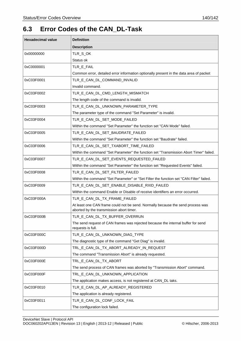
Status/Error Codes Overview 140/142
DeviceNet Slave | Protocol API DOC060202API13EN | Revision 13 | English | 2013-12 | Released | Public © Hilscher, 2006-2013
6.3 Error Codes of the CAN_DL-Task
Hexadecimal value Definition
Description
0x00000000 TLR_S_OK
Status ok
0xC0000001 TLR_E_FAIL
Common error, detailed error information optionally present in the data area of packet
0xC03F0001 TLR_E_CAN_DL_COMMAND_INVALID
Invalid command.
0xC03F0002 TLR_E_CAN_DL_CMD_LENGTH_MISMATCH
The length code of the command is invalid.
0xC03F0003 TLR_E_CAN_DL_UNKNOWN_PARAMETER_TYPE
The parameter type of the command "Set Parameter" is invalid.
0xC03F0004 TLR_E_CAN_DL_SET_MODE_FAILED
Within the command "Set Parameter" the function set "CAN Mode" failed.
0xC03F0005 TLR_E_CAN_DL_SET_BAUDRATE_FAILED
Within the command "Set Parameter" the function set "Baudrate" failed.
0xC03F0006 TLR_E_CAN_DL_SET_TXABORT_TIME_FAILED
Within the command "Set Parameter" the function set "Transmission Abort Timer" failed.
0xC03F0007 TLR_E_CAN_DL_SET_EVENTS_REQUESTED_FAILED
Within the command "Set Parameter" the function set "Requested Events" failed.
0xC03F0008 TLR_E_CAN_DL_SET_FILTER_FAILED
Within the command "Set Parameter" or "Set Filter the function set "CAN Filter" failed.
0xC03F0009 TLR_E_CAN_DL_SET_ENABLE_DISABLE_RXID_FAILED
Within the command Enable or Disable of receive identifiers an error occurred.
0xC03F000A TLR_E_CAN_DL_TX_FRAME_FAILED
At least one CAN frame could not be send. Normally because the send process was aborted by the transmission abort timer.
0xC03F000B TLR_E_CAN_DL_TX_BUFFER_OVERRUN
The send request of CAN frames was rejected because the internal buffer for send requests is full.
0xC03F000C TLR_E_CAN_DL_UNKNOWN_DIAG_TYPE
The diagnostic type of the command "Get Diag" is invalid.
0xC03F000D TRL_E_CAN_DL_TX_ABORT_ALREADY_IN_REQUEST
The command "Transmission Abort" is already requested.
0xC03F000E TRL_E_CAN_DL_TX_ABORT
The send process of CAN frames was aborted by "Transmission Abort" command.
0xC03F000F TRL_E_CAN_DL_UNKNOWN_APPLICATION
The application makes access, is not registered at CAN_DL taks.
0xC03F0010 TLR_E_CAN_DL_AP_ALREADY_REGISTERED
The application is already registered.
0xC03F0011 TLR_E_CAN_DL_CONF_LOCK_FAIL
The configuration lock failed.

Status/Error Codes Overview 141/142
DeviceNet Slave | Protocol API DOC060202API13EN | Revision 13 | English | 2013-12 | Released | Public © Hilscher, 2006-2013
Hexadecimal value Definition
Description
0xC03F0012 TLR_E_CAN_DL_CONF_LOCKED
The configuration is locked.
Table 90: Error Codes of the CAN_DL-Task
Contacts 142/142
DeviceNet Slave | Protocol API DOC060202API13EN | Revision 13 | English | 2013-12 | Released | Public © Hilscher, 2006-2013
7 Contacts
Headquarters Germany Hilscher Gesellschaft für Systemautomation mbH Rheinstrasse 15 65795 Hattersheim Phone: +49 (0) 6190 9907-0 Fax: +49 (0) 6190 9907-50 E-Mail: [email protected] Support Phone: +49 (0) 6190 9907-99 E-Mail: [email protected]
Subsidiaries
China Hilscher Systemautomation (Shanghai) Co. Ltd. 200010 Shanghai Phone: +86 (0) 21-6355-5161 E-Mail: [email protected] Support Phone: +86 (0) 21-6355-5161 E-Mail: [email protected] France Hilscher France S.a.r.l. 69500 Bron Phone: +33 (0) 4 72 37 98 40 E-Mail: [email protected] Support Phone: +33 (0) 4 72 37 98 40 E-Mail: [email protected] India Hilscher India Pvt. Ltd. New Delhi - 110 065 Phone: +91 11 26915430 E-Mail: [email protected] Italy Hilscher Italia S.r.l. 20090 Vimodrone (MI) Phone: +39 02 25007068 E-Mail: [email protected] Support Phone: +39 02 25007068 E-Mail: [email protected]
Japan Hilscher Japan KK Tokyo, 160-0022 Phone: +81 (0) 3-5362-0521 E-Mail: [email protected] Support Phone: +81 (0) 3-5362-0521 E-Mail: [email protected] Korea Hilscher Korea Inc. Seongnam, Gyeonggi, 463-400 Phone: +82 (0) 31-789-3715 E-Mail: [email protected] Switzerland Hilscher Swiss GmbH 4500 Solothurn Phone: +41 (0) 32 623 6633 E-Mail: [email protected] Support Phone: +49 (0) 6190 9907-99 E-Mail: [email protected] USA Hilscher North America, Inc. Lisle, IL 60532 Phone: +1 630-505-5301 E-Mail: [email protected] Support Phone: +1 630-505-5301 E-Mail: [email protected]