DeviceNet Operation Manual - Omron€¦ · DeviceNet Operation Manual (this man-ual) Describes the...
163
DeviceNet Cat. No. W267-E1-11 OPERATION MANUAL
Transcript of DeviceNet Operation Manual - Omron€¦ · DeviceNet Operation Manual (this man-ual) Describes the...

DeviceNet
Cat. No. W267-E1-11
OPERATION MANUAL

DeviceNet Operation ManualRevised April 2008

iv

Notice:OMRON products are manufactured for use according to proper procedures by a qualified operatorand only for the purposes described in this manual.
The following conventions are used to indicate and classify precautions in this manual. Always heedthe information provided with them. Failure to heed precautions can result in injury to people or dam-age to property.
!DANGER Indicates an imminently hazardous situation which, if not avoided, will result in death orserious injury. Additionally, there may be severe property damage.
!WARNING Indicates a potentially hazardous situation which, if not avoided, could result in death orserious injury. Additionally, there may be severe property damage.
!Caution Indicates a potentially hazardous situation which, if not avoided, may result in minor ormoderate injury, or property damage.
OMRON Product ReferencesAll OMRON products are capitalized in this manual. The word “Unit” is also capitalized when it refers toan OMRON product, regardless of whether or not it appears in the proper name of the product.
The abbreviation “Ch,” which appears in some displays and on some OMRON products, often means“word” and is abbreviated “Wd” in documentation in this sense.
The abbreviation “PLC” means Programmable Controller. “PC” is used, however, in some Program-ming Device displays to mean Programmable Controller.
Visual AidsThe following headings appear in the left column of the manual to help you locate different types ofinformation.
Note Indicates information of particular interest for efficient and convenient opera-tion of the product.
1,2,3... 1. Indicates lists of one sort or another, such as procedures, checklists, etc.
Trademarks and CopyrightsCOMBICON is a registered trademark of PHOENIX CONTACT.
DeviceNet is a registered trademark of the Open DeviceNet Vendor Association, Inc.
PowerTap is a registered trademark of the Allen-Bradley Company, Inc.
OMRON, 1996All rights reserved. No part of this publication may be reproduced, stored in a retrieval system, or transmitted, in any form, orby any means, mechanical, electronic, photocopying, recording, or otherwise, without the prior written permission ofOMRON.
No patent liability is assumed with respect to the use of the information contained herein. Moreover, because OMRON is con-stantly striving to improve its high-quality products, the information contained in this manual is subject to change withoutnotice. Every precaution has been taken in the preparation of this manual. Nevertheless, OMRON assumes no responsibilityfor errors or omissions. Neither is any liability assumed for damages resulting from the use of the information contained inthis publication.
v

vi

TABLE OF CONTENTS
PRECAUTIONS . . . . . . . . . . . . . . . . . . . . . . . . . . . . . . . . . . . xv1 Intended Audience . . . . . . . . . . . . . . . . . . . . . . . . . . . . . . . . . . . . . . . . . . . . . . . . . . . . . . . . . xvi
2 General Precautions . . . . . . . . . . . . . . . . . . . . . . . . . . . . . . . . . . . . . . . . . . . . . . . . . . . . . . . . xvii
3 Safety Precautions . . . . . . . . . . . . . . . . . . . . . . . . . . . . . . . . . . . . . . . . . . . . . . . . . . . . . . . . . xviii
4 Operating Environment Precautions . . . . . . . . . . . . . . . . . . . . . . . . . . . . . . . . . . . . . . . . . . . xx
5 Application Precautions. . . . . . . . . . . . . . . . . . . . . . . . . . . . . . . . . . . . . . . . . . . . . . . . . . . . . xxi
SECTION 1Introduction. . . . . . . . . . . . . . . . . . . . . . . . . . . . . . . . . . . . . . . 1
1-1 DeviceNet Network Features. . . . . . . . . . . . . . . . . . . . . . . . . . . . . . . . . . . . . . . . . . . . . . . . . 2
1-2 DeviceNet-compatible Devices . . . . . . . . . . . . . . . . . . . . . . . . . . . . . . . . . . . . . . . . . . . . . . . 4
1-3 Communications Specifications . . . . . . . . . . . . . . . . . . . . . . . . . . . . . . . . . . . . . . . . . . . . . . 17
1-4 Basic Operating Procedures. . . . . . . . . . . . . . . . . . . . . . . . . . . . . . . . . . . . . . . . . . . . . . . . . . 18
SECTION 2Network Configuration and Wiring . . . . . . . . . . . . . . . . . . . 21
2-1 Network Configuration Overview . . . . . . . . . . . . . . . . . . . . . . . . . . . . . . . . . . . . . . . . . . . . . 22
2-2 Network Configuration . . . . . . . . . . . . . . . . . . . . . . . . . . . . . . . . . . . . . . . . . . . . . . . . . . . . . 32
2-3 Cables, Connectors, and Related Devices . . . . . . . . . . . . . . . . . . . . . . . . . . . . . . . . . . . . . . . 43
2-4 Wiring Methods . . . . . . . . . . . . . . . . . . . . . . . . . . . . . . . . . . . . . . . . . . . . . . . . . . . . . . . . . . . 62
2-5 Minimizing Noise in the Network . . . . . . . . . . . . . . . . . . . . . . . . . . . . . . . . . . . . . . . . . . . . . 82
2-6 Operational Checklist . . . . . . . . . . . . . . . . . . . . . . . . . . . . . . . . . . . . . . . . . . . . . . . . . . . . . . 85
SECTION 3Communications Power Supply Methods. . . . . . . . . . . . . . . 87
3-1 Basic Concepts. . . . . . . . . . . . . . . . . . . . . . . . . . . . . . . . . . . . . . . . . . . . . . . . . . . . . . . . . . . . 88
3-2 Flowchart: Determining Power Supply Requirements . . . . . . . . . . . . . . . . . . . . . . . . . . . . . 89
3-3 Locating the Power Supply . . . . . . . . . . . . . . . . . . . . . . . . . . . . . . . . . . . . . . . . . . . . . . . . . . 90
3-4 Step 1: Evaluating the Configuration with Graphs . . . . . . . . . . . . . . . . . . . . . . . . . . . . . . . . 92
3-5 Step 2: Evaluating the Configuration with Calculations . . . . . . . . . . . . . . . . . . . . . . . . . . . . 96
3-6 Step 3: Splitting the System into Multiple Power Supplies. . . . . . . . . . . . . . . . . . . . . . . . . . 101
AppendicesA Connectable Device Lists . . . . . . . . . . . . . . . . . . . . . . . . . . . . . . . . . . . . . . . . . . . . . . . . . . . 103
B Dimensions of Connectable Devices . . . . . . . . . . . . . . . . . . . . . . . . . . . . . . . . . . . . . . . . . . 119
C Current Consumption of DeviceNet Devices . . . . . . . . . . . . . . . . . . . . . . . . . . . . . . . . . . . . 131
Index. . . . . . . . . . . . . . . . . . . . . . . . . . . . . . . . . . . . . . . . . . . . . 137
Revision History . . . . . . . . . . . . . . . . . . . . . . . . . . . . . . . . . . . 141
vii

viii

About this Manual:
This manual describes the configuration and installation of an OMRON DeviceNet network andincludes the sections described below.
Please read this manual carefully and be sure you understand the information provided beforeattempting to install or operate the DeviceNet network. Be sure to read the precautions provided inthe following section.
The following manuals also cover information related to DeviceNet applications. Use the DeviceNetOperation Manual together with other required manuals.
Precautions provides general precautions for planning, installing, and operating the DeviceNet net-work and related devices.
Section 1 provides an overview of the DeviceNet network, including features, compatible OMRONDeviceNet devices, communications specifications, and basic operating procedures.
Section 2 explains how to plan the Network configuration and connect the Network’s communicationswiring.
Section 3 describes the DeviceNet communications power supply methods and provides a step-by-step procedure to determine the ideal location for the power supply (or power supplies.)
Appendix A provides lists of OMRON’s DeviceNet devices.
Appendix B shows the dimensions of the DeviceNet devices.
Appendix C shows the current requirements of the DeviceNet devices.
Manual Contents Cat. No.
DeviceNet Operation Manual (this man-ual)
Describes the configuration and construction of a DeviceNet network, including installation procedures and specifications for cables, connec-tors, and other connection devices, as well as information on functions, operating procedures, and applications.
W267
DeviceNet CS/CJ Series Units Operation Manual
Describes the models, specifications, functions, operating procedures, and applications of CS-series and CJ-series DeviceNet Master Units.
W380
DeviceNet Masters Operation Manual
Describes the models, specifications, functions, operating procedures, and applications of C200HX/HG/HE, CVM1, and CV-series DeviceNet Master Units.
W379
DeviceNet DRT1 Series Slaves Operation Manual
Describes the models, specifications, functions, operating procedures, and applications of DRT1-series Smart Slave Units.
W347
DeviceNet DRT2 Series Slaves Operation Manual
Describes the models, specifications, functions, operating procedures, and applications of DRT2-series Smart Slave Units.
W404
DeviceNet Configurator Ver. 2.@ Operation Manual
Describes the operating procedures of the DeviceNet Configurator. W382
DeviceNet MULTIPLE I/O TERMINAL Operation Manual
Describes the models, specifications, functions, operating procedures, and applications of the DeviceNet MULTIPLE I/O TERMINALs.
W348
!WARNING Failure to read and understand the information provided in this manual may result in per-sonal injury or death, damage to the product, or product failure. Please read each sectionin its entirety and be sure you understand the information provided in the section andrelated sections before attempting any of the procedures or operations given.
ix

x

Read and Understand this ManualPlease read and understand this manual before using the product. Please consult your OMRON representative if you have any questions or comments.
Warranty and Limitations of Liability
WARRANTY
OMRON's exclusive warranty is that the products are free from defects in materials and workmanship for a period of one year (or other period if specified) from date of sale by OMRON.
OMRON MAKES NO WARRANTY OR REPRESENTATION, EXPRESS OR IMPLIED, REGARDING NON-INFRINGEMENT, MERCHANTABILITY, OR FITNESS FOR PARTICULAR PURPOSE OF THE PRODUCTS. ANY BUYER OR USER ACKNOWLEDGES THAT THE BUYER OR USER ALONE HAS DETERMINED THAT THE PRODUCTS WILL SUITABLY MEET THE REQUIREMENTS OF THEIR INTENDED USE. OMRON DISCLAIMS ALL OTHER WARRANTIES, EXPRESS OR IMPLIED.
LIMITATIONS OF LIABILITY
OMRON SHALL NOT BE RESPONSIBLE FOR SPECIAL, INDIRECT, OR CONSEQUENTIAL DAMAGES, LOSS OF PROFITS OR COMMERCIAL LOSS IN ANY WAY CONNECTED WITH THE PRODUCTS, WHETHER SUCH CLAIM IS BASED ON CONTRACT, WARRANTY, NEGLIGENCE, OR STRICT LIABILITY.
In no event shall the responsibility of OMRON for any act exceed the individual price of the product on which liability is asserted.
IN NO EVENT SHALL OMRON BE RESPONSIBLE FOR WARRANTY, REPAIR, OR OTHER CLAIMS REGARDING THE PRODUCTS UNLESS OMRON'S ANALYSIS CONFIRMS THAT THE PRODUCTS WERE PROPERLY HANDLED, STORED, INSTALLED, AND MAINTAINED AND NOT SUBJECT TO CONTAMINATION, ABUSE, MISUSE, OR INAPPROPRIATE MODIFICATION OR REPAIR.
xi

Application Considerations
SUITABILITY FOR USE
OMRON shall not be responsible for conformity with any standards, codes, or regulations that apply to the combination of products in the customer's application or use of the products.
At the customer's request, OMRON will provide applicable third party certification documents identifying ratings and limitations of use that apply to the products. This information by itself is not sufficient for a complete determination of the suitability of the products in combination with the end product, machine, system, or other application or use.
The following are some examples of applications for which particular attention must be given. This is not intended to be an exhaustive list of all possible uses of the products, nor is it intended to imply that the uses listed may be suitable for the products:
• Outdoor use, uses involving potential chemical contamination or electrical interference, or conditions or uses not described in this manual.
• Nuclear energy control systems, combustion systems, railroad systems, aviation systems, medical equipment, amusement machines, vehicles, safety equipment, and installations subject to separate industry or government regulations.
• Systems, machines, and equipment that could present a risk to life or property.
Please know and observe all prohibitions of use applicable to the products.
NEVER USE THE PRODUCTS FOR AN APPLICATION INVOLVING SERIOUS RISK TO LIFE OR PROPERTY WITHOUT ENSURING THAT THE SYSTEM AS A WHOLE HAS BEEN DESIGNED TO ADDRESS THE RISKS, AND THAT THE OMRON PRODUCTS ARE PROPERLY RATED AND INSTALLED FOR THE INTENDED USE WITHIN THE OVERALL EQUIPMENT OR SYSTEM.
PROGRAMMABLE PRODUCTS
OMRON shall not be responsible for the user's programming of a programmable product, or any consequence thereof.
xii

Disclaimers
CHANGE IN SPECIFICATIONS
Product specifications and accessories may be changed at any time based on improvements and other reasons.
It is our practice to change model numbers when published ratings or features are changed, or when significant construction changes are made. However, some specifications of the products may be changed without any notice. When in doubt, special model numbers may be assigned to fix or establish key specifications for your application on your request. Please consult with your OMRON representative at any time to confirm actual specifications of purchased products.
DIMENSIONS AND WEIGHTS
Dimensions and weights are nominal and are not to be used for manufacturing purposes, even when tolerances are shown.
PERFORMANCE DATA
Performance data given in this manual is provided as a guide for the user in determining suitability and does not constitute a warranty. It may represent the result of OMRON's test conditions, and the users must correlate it to actual application requirements. Actual performance is subject to the OMRON Warranty and Limitations of Liability.
ERRORS AND OMISSIONS
The information in this manual has been carefully checked and is believed to be accurate; however, no responsibility is assumed for clerical, typographical, or proofreading errors, or omissions.
xiii

xiv

PRECAUTIONS
This section provides general precautions for installing and using the DeviceNet network and related devices.
The information contained in this section is important for the safe and reliable application of the DeviceNet network.You must read this section and understand the information contained before attempting to set up or operate aDeviceNet network.
1 Intended Audience . . . . . . . . . . . . . . . . . . . . . . . . . . . . . . . . . . . . . . . . . . . . . xvi2 General Precautions . . . . . . . . . . . . . . . . . . . . . . . . . . . . . . . . . . . . . . . . . . . . xvii3 Safety Precautions. . . . . . . . . . . . . . . . . . . . . . . . . . . . . . . . . . . . . . . . . . . . . . xviii4 Operating Environment Precautions . . . . . . . . . . . . . . . . . . . . . . . . . . . . . . . . xx5 Application Precautions . . . . . . . . . . . . . . . . . . . . . . . . . . . . . . . . . . . . . . . . . xxi
xv

Intended Audience 1
1 Intended AudienceThis manual is intended for the following personnel, who must also haveknowledge of electrical systems (an electrical engineer or the equivalent).
• Personnel in charge of purchasing FA systems.
• Personnel in charge of designing FA systems.
• Personnel in charge of installing and connecting FA systems.
• Personnel in charge of managing FA systems and facilities.
xvi

General Precautions 2
2 General PrecautionsThe user must operate the product according to the specifications describedin the operation manuals.
Before using the product under conditions which are not described in themanual or applying the product to nuclear control systems, railroad systems,aviation systems, vehicles, combustion systems, medical equipment, amuse-ment machines, safety equipment, and other systems, machines, and equip-ment that may have a serious influence on lives and property if usedimproperly, consult your OMRON representative.
Make sure that the ratings and performance characteristics of the product aresufficient for the systems, machines, and equipment, and be sure to providethe systems, machines, and equipment with redundant safety mechanisms.
This manual provides information for installing and operating OMRONDeviceNet products. Be sure to read this manual before operation and keepthis manual close at hand for reference during operation.
!WARNING It is extremely important that a PLC and all PLC Units be used for the speci-fied purpose and under the specified conditions, especially in applications thatcan directly or indirectly affect human life. You must consult with your OMRONrepresentative before applying a PLC system to the above mentioned applica-tions.
xvii
Safety Precautions 3
3 Safety Precautions
!WARNING Never attempt to disassemble any Units while power is being supplied. Doingso may result in serious electrical shock or electrocution.
!WARNING Make sure that the current or voltage input to the Unit is within the specifiedranges. Using a current or voltage outside of the specified range may result indamage or fire.
!WARNING Provide safety measures in external circuits (i.e., not in the ProgrammableController), including the following items, to ensure safety in the system if anabnormality occurs due to malfunction of the PLC or another external factoraffecting the PLC operation. Not doing so may result in serious accidents.
1. Emergency stop circuits, interlock circuits, limit circuits, and similar safetymeasures must be provided in external control circuits.
2. The PLC will turn OFF all outputs when its self-diagnosis function detectsany error or when a severe failure alarm (FALS) instruction is executed. Ex-ternal safety measures must be provided to ensure safety in the system incase an error or FALS instruction causes all outputs to be turned OFF.
3. The PLC outputs may remain ON or OFF due to fusing or burning of theoutput relay contacts or destruction of the output transistors. External safe-ty measures must be provided to ensure safety in the system in case theoutputs fail and remain ON or OFF.
4. When the 24-V DC output (service power supply to the PLC) is overloadedor short-circuited, the voltage may drop and result in the outputs beingturned OFF. External safety measures must be provided to ensure safetyin the system in case of a power supply problem that causes outputs to beturned OFF.
!WARNING The PLC’s CPU Unit continues I/O refreshing even when the program is notbeing executed (in PROGRAM mode). Before proceeding with any of the fol-lowing operations, verify that it is safe to do so in case the operation changesthe status of output bits allocated to Output Units or the data allocated to Spe-cial I/O Units or CPU Bus Units. It is possible for a load connected to an Out-put Unit, Special I/O Unit, or CPU Bus Unit to operate unexpectedly.
• Using a Programming Device (Support Software in a personal computer)to transfer data to the CPU Unit’s I/O memory area.
• Using a Programming Device to change present values
• Using a Programming Device to force-set or force-reset bits
• Transferring an I/O memory file to the CPU Unit from EM file memory
• Transferring I/O memory from another PLC or host computer in the net-work
!Caution Execute online edit only after confirming that no adverse effects will becaused by extending the cycle time. Otherwise, the input signals may not bereadable.
xviii

Safety Precautions 3
!Caution Confirm safety at the destination node before transferring or changing the pro-gram, PLC Setup, I/O table, or I/O memory in another node. Changing data inanother node without confirming safety may cause unexpected operation andresult in injury.
xix
Operating Environment Precautions 4
4 Operating Environment PrecautionsInstall the system properly according to the directions in this manual.
Do not operate the control system in the following places.
• Locations subject to direct sunlight.
• Locations subject to temperatures or humidity outside the range specifiedin the specifications.
• Locations subject to condensation as the result of severe changes in tem-perature.
• Locations subject to corrosive or flammable gases.
• Locations subject to dust (especially iron dust) or salts.
• Locations subject to water, oil, or chemicals.
• Locations subject to shock or vibration.
Take appropriate and sufficient countermeasures when installing systems inthe following locations:
• Locations subject to static electricity or other forms of noise.
• Locations subject to strong electromagnetic fields.
• Locations subject to possible exposure to radioactivity.
• Locations close to power supplies.
xx
Application Precautions 5
5 Application Precautions• Fail-safe measures must be taken by the customer to ensure safety in the
event of incorrect, missing, or abnormal signals caused by broken signallines, momentary power interruptions, or other causes.
• Emergency stop circuits, interlock circuits, limit circuits, and similar safetymeasures must be provided in external control circuits (i.e., not in the Pro-grammable Controller).
• Use the power supplies specified in the operation manuals.
• If the system is installed at a site with poor power supply conditions, takeappropriate measures to ensure that the power supply remains within therated voltage and frequency specifications.
• Install external breakers and take other safety measures against short-cir-cuiting in external wiring. Insufficient safety measures against short-cir-cuiting may result in burning.
• Always ground the system to 100 Ω or less when installing the system toprotect against electrical shock.
• Make sure that the Unit is securely mounted, either to the DIN Track or byscrews.
• Always turn OFF the communications power supply and the power sup-plies to the PLC and Slaves before attempting any of the following.
• Mounting or removing a Unit such as an I/O Unit, Power Supply Unit,CPU Unit, Memory Cassette, or Master Unit.
• Connecting or disconnecting Remote I/O Terminal circuits.
• Assembling any devices or racks.
• Setting DIP switches or rotary switches.
• Connecting or wiring cables.
• Connecting or disconnecting connectors.
• Do not attempt to disassemble, repair, or modify any Units.
• Make sure that the terminal block screws are tightened to the torquespecified in the relevant manuals. Loose screws may result in fire, mal-function, or damage.
• Confirm that no adverse effect will occur in the system before attemptingany of the following.
• Changing the operating mode of the PLC (including the operatingmode setting when the power is turned ON)
• Force-setting/force-resetting any bit in memory
• Changing the present value of any word or any set value in memory
• Make sure that all the mounting screws, terminal screws, and cable con-nector screws are tightened to the torque specified in the relevant manu-als.
• Make sure that communications connector screws are securely tightenedto a torque of 0.5 to 0.6 N·m.
• Use crimp terminals for wiring. Do not connect bare stranded wiresdirectly to terminals.
• Double-check all wiring and switch settings before turning ON the powersupply.
• Make sure that metal filings do not get inside of the Unit during wiring andinstallation.
xxi
Application Precautions 5
• Make sure that the polarity of terminals, the wiring of communicationspaths, the wiring of the power supply, and the voltage for inputs and out-puts are correct. If any of these are incorrect, it may result in damage.
• Perform the wiring correctly according to the instructions in this manual.
• Make sure that the connection distances are within specifications.
• Mount Units only after checking terminal blocks and connectors com-pletely.
• Make sure that the communications cable connectors and other itemswith locking devices are properly locked into place.
• Do not drop the Unit or subject it to abnormal vibration or impact, or it mayresult in damage or malfunctioning.
• Use the special packing box when transporting the Unit. Ensure that theproduct is handled carefully so that no excessive vibration or impact isapplied to the product during transportation.
• Check the user program for proper execution before actually running itwith the system.
• Do not pull on the cables or bend them past their natural bending radius.
• Before connecting communications cables, be sure to first turn OFF thecommunications power supply, the power supply to the PLC, and thepower supply to all Slaves.
• Use only the specified DeviceNet cables as communications cables.
• Observe the following precautions when wiring the communicationscables.
• Wire the cables separately from the power lines or high-tension lines.
• Do not bend the cables excessively.
• Do not pull on the cables excessively.
• Do not place objects on top of the cables.
• Route cables inside ducts.
• Before touching a Unit, touch a grounded metallic object in order to dis-charge any static build-up.
• Always enable the scan list before operation.
• Before clearing the scan list for a Unit set for automatic allocation ofremote I/O, make sure that it will not cause any problems for the I/O areato be changed to fixed allocations.
• When adding a new node to the network, check that the new node’s baudrate is the same as the baud rate set on the other nodes.
• When a CPU Unit or Special I/O Unit is being replaced, always transferany required data, such as DM and HR area settings and parameters,before restarting the system.
• Follow the specifications for the communications distances and the num-ber of connected Units.
xxii

SECTION 1Introduction
This section provides an overview of the DeviceNet network, including features, specifications, and the system configurations.
1-1 DeviceNet Network Features . . . . . . . . . . . . . . . . . . . . . . . . . . . . . . . . . . . . . 2
1-1-1 Reduced Wiring . . . . . . . . . . . . . . . . . . . . . . . . . . . . . . . . . . . . . . . . 2
1-1-2 Multi-vendor Networks. . . . . . . . . . . . . . . . . . . . . . . . . . . . . . . . . . . 2
1-1-3 Remote I/O Communications and Message Communications . . . . . 3
1-1-4 Device Profiles . . . . . . . . . . . . . . . . . . . . . . . . . . . . . . . . . . . . . . . . . 3
1-2 DeviceNet-compatible Devices. . . . . . . . . . . . . . . . . . . . . . . . . . . . . . . . . . . . 4
1-2-1 Master Unit Models . . . . . . . . . . . . . . . . . . . . . . . . . . . . . . . . . . . . . 4
1-2-2 DeviceNet Functions of OMRON Master Units. . . . . . . . . . . . . . . . 4
1-2-3 Types of Slaves . . . . . . . . . . . . . . . . . . . . . . . . . . . . . . . . . . . . . . . . . 7
1-2-4 DeviceNet Configurator . . . . . . . . . . . . . . . . . . . . . . . . . . . . . . . . . . 17
1-3 Communications Specifications . . . . . . . . . . . . . . . . . . . . . . . . . . . . . . . . . . . 17
1-4 Basic Operating Procedures . . . . . . . . . . . . . . . . . . . . . . . . . . . . . . . . . . . . . . 18
1-4-1 DeviceNet Network Configuration and Wiring . . . . . . . . . . . . . . . . 18
1-4-2 Network Start-up Procedure . . . . . . . . . . . . . . . . . . . . . . . . . . . . . . . 18
1

DeviceNet Network Features Section 1-1
1-1 DeviceNet Network FeaturesDeviceNet is an open field network that can easily connect a variety of controldevices such as PLCs, personal computers, sensors, and actuators.
The DeviceNet network not only reduces wiring and maintenance costsbecause it requires less wiring, it also allows DeviceNet-compatible devicesfrom different manufacturers to be connected. There is a wide selection ofDeviceNet-compatible devices available, so a more economical system canbe constructed.
1-1-1 Reduced WiringUse DeviceNet cables to wire connections such as multi-drop trunk lines andT-branch lines. These connection methods can help reduce onsite wiringcosts and maintenance costs.
1-1-2 Multi-vendor NetworksThe DeviceNet communications specifications are open and standardized, soa DeviceNet-compatible device from any manufacturer can be connected.DeviceNet can be used in a variety of field-level applications by combiningdevices such as valves and sensors.
Multi-drop trunk line T-branch multi-drop branch Trunk lineT-branch Connector
Branch line
Trunk lineTrunk line
Branch lineBranch lines
DeviceNet
OMRON Master Unit Another Company’s Master Unit
Another Company’s Slave Units
OMRON Slave Units
2
DeviceNet Network Features Section 1-1
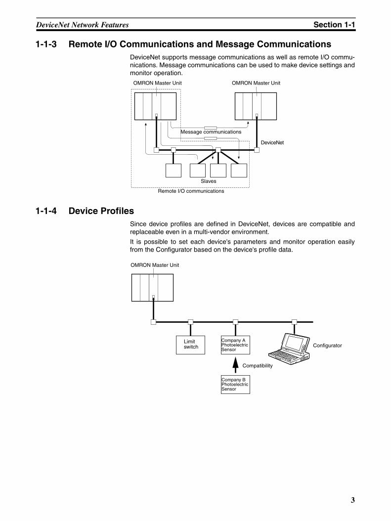
1-1-3 Remote I/O Communications and Message CommunicationsDeviceNet supports message communications as well as remote I/O commu-nications. Message communications can be used to make device settings andmonitor operation.
1-1-4 Device ProfilesSince device profiles are defined in DeviceNet, devices are compatible andreplaceable even in a multi-vendor environment.
It is possible to set each device's parameters and monitor operation easilyfrom the Configurator based on the device's profile data.
DeviceNet
OMRON Master Unit
Remote I/O communications
Slaves
OMRON Master Unit
Message communications
OMRON Master Unit
ConfiguratorLimit switch
Company A Photoelectric Sensor
Company B Photoelectric Sensor
Compatibility
3
DeviceNet-compatible Devices Section 1-2
1-2 DeviceNet-compatible Devices
1-2-1 Master Unit Models
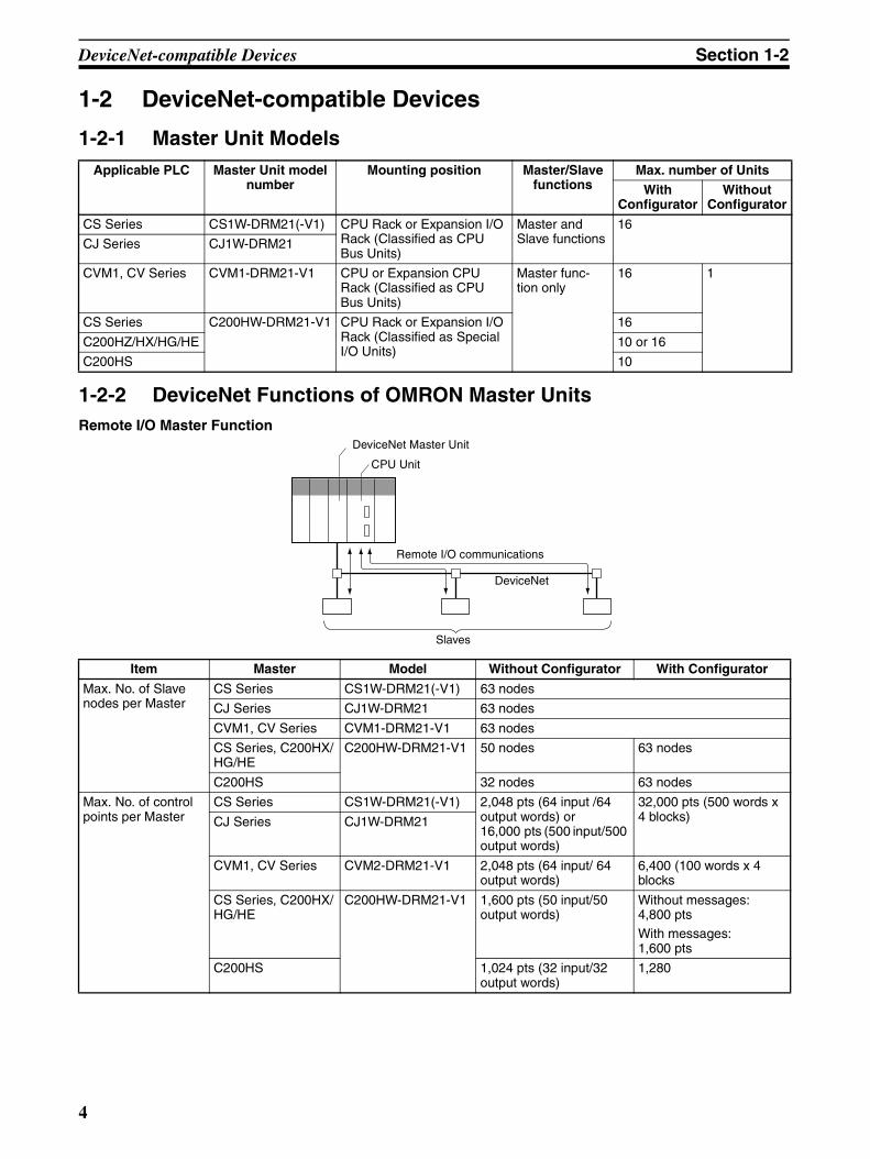
1-2-2 DeviceNet Functions of OMRON Master UnitsRemote I/O Master Function
Applicable PLC Master Unit model number
Mounting position Master/Slave functions
Max. number of Units
WithConfigurator
WithoutConfigurator
CS Series CS1W-DRM21(-V1) CPU Rack or Expansion I/O Rack (Classified as CPU Bus Units)
Master and Slave functions
16
CJ Series CJ1W-DRM21
CVM1, CV Series CVM1-DRM21-V1 CPU or Expansion CPU Rack (Classified as CPU Bus Units)
Master func-tion only
16 1
CS Series C200HW-DRM21-V1 CPU Rack or Expansion I/O Rack (Classified as Special I/O Units)
16
C200HZ/HX/HG/HE 10 or 16
C200HS 10
DeviceNet
DeviceNet Master Unit
CPU Unit
Remote I/O communications
Slaves
Item Master Model Without Configurator With Configurator
Max. No. of Slave nodes per Master
CS Series CS1W-DRM21(-V1) 63 nodes
CJ Series CJ1W-DRM21 63 nodes
CVM1, CV Series CVM1-DRM21-V1 63 nodes
CS Series, C200HX/HG/HE
C200HW-DRM21-V1 50 nodes 63 nodes
C200HS 32 nodes 63 nodes
Max. No. of control points per Master
CS Series CS1W-DRM21(-V1) 2,048 pts (64 input /64 output words) or 16,000 pts (500 input/500 output words)
32,000 pts (500 words x 4 blocks)CJ Series CJ1W-DRM21
CVM1, CV Series CVM2-DRM21-V1 2,048 pts (64 input/ 64 output words)
6,400 (100 words x 4 blocks
CS Series, C200HX/HG/HE
C200HW-DRM21-V1 1,600 pts (50 input/50 output words)
Without messages:4,800 ptsWith messages:1,600 pts
C200HS 1,024 pts (32 input/32 output words)
1,280
4

DeviceNet-compatible Devices Section 1-2
Remote I/O Slave Function
Max. No. of I/O points per Slave con-trollable by Master
CS Series CS1W-DRM21(-V1) 100 input words x 2/100 output words x 1
CJ Series CJ1W-DRM21
CVM1, CV Series CVM1-DRM21-V1 32 input/32 output words
CS Series, C200HX/HG/HE
C200HW-DRM21-V1
C200HS
Remote I/O alloca-tion areas
CS Series CS1W-DRM21(-V1) CS/CJ DeviceNet words in CIO Area, and user-allocated words in CIO Area, DM Area, and other areas.
User-allocated words in CIO Area, DM Area, and other areas.
CJ Series CJ1W-DRM21
CVM1, CV Series CVM1-DRM21-V1 DeviceNet Area (includ-ing dedicated words/ bits)
User-allocated words in CIO Area, DM Area, and other areas.
CS Series, C200HX/HG/HE
C200HW-DRM21-V1
C200HS
Item Master Model Without Configurator With Configurator
DeviceNet
DeviceNet Master UnitCPU Unit
IN area OUT area
IN area OUT area
Remote I/O communications
Slaves
CS-series CPU Unit
CS or CJ Series DeviceNet Unit (Slave function)I/O Link Unit (Slave)
Item CPU Unit to which a Slave is mounted
Unit Model Without the Configurator
With the Configurator
Max. No. of I/O pts per Slave
CS Series CS1W-DRM21(-V1) 32 pts (1 input/ 1 output word) or 3,200 pts (100 input/100 output words)
4,800 pts (100 input words x 2/100 output words x 1)
CJ Series CJ1W-DRM21
CS Series, C200HX/HG/HE
C200HW-DRT21 1,024 pts (32 input/32 output words)
CQM1HCQM1 Series
CQM1-DRT21 32 pts (1 input/1 output word)
Allocation areas in the CPU Unit to which this Slave is mounted
CS Series CS1W-DRM21(-V1) CIO, WR, DM, EM, HR
CJ Series CJ1W-DRM21
CS Series, C200HX/HG/HE
C200HW-DRM21 CIO, DM, EM, AR, LR, T/C
CQM1HCQM1 Series
CQM1-DRT21 CIO
5

DeviceNet-compatible Devices Section 1-2
Message Communications Function
[ CMND ... ]
Master
Special Slave
Master
Item Master Unit model Send Receive FINS commands
Communications Instructions
CS Series CS1W-DRM21(-V1) SEND(192) RECV(193) CMND(194)
CJ Series CJ1W-DRM21 SEND(192) RECV(193) CMND(194)
CVM1, CV Series DVM1-DRM21-V1 SEND(192) RECV(193) CMND(194)
CS Series,C200HX/HG/HE
C200HW-DRM21-V1 None None IOWR
C200HS ---
Item Master model Model Capacity
Max. No. of nodes per Master for message communications using FINS commands
CS Series CS1W-DRM21(-V1) 63 nodes
CJ Series CJ1W-DRM21
CVM1, CV Series CVM1-DRM21-V1 8 nodes
CS Series, C200HX/HG/HE
C200HW-DRM21-V1 8 nodes
C200HS Not supported
Max. No. of nodes per Master for message communications using explicit messages
CS Series CS1W-DRM21(-V1) 63 nodes
CJ Series CJ1W-DRM21
CVM1, CV Series CVM1-DRM21-V1 63 nodes
CS Series, C200HX/HG/HE
C200HW-DRM21-V1 63 nodes
C200HS Not supported
Max. message length CS Series CS1W-DRM21(-V1) SEND(192): 267 wordsRECV(193): 269 wordsCMND(194): 542 bytes (starting with command code)
CJ Series CJ1W-DRM21
CVM1, CV Series CVM1-DRM21-V1 SEND(192): 76 words
RECV(193): 78 wordsCMND(194): 160 bytes(starting with command code)
CS Series, C200HX/HG/HE
C200HW-DRM21-V1 IOWR(223): 160 bytes (starting with command code)
6

DeviceNet-compatible Devices Section 1-2
1-2-3 Types of SlavesThe following classifications are used for DeviceNet Slaves.
For more details on the General-purpose Slaves, Environment-resistiveSlaves, and Special Slaves, refer to the DeviceNet DRT1 Series Slaves Oper-ation Manual (W347) for DRT1-series Slaves and the DeviceNet DRT2 SeriesSlaves Operation Manual (W404) for DRT2-series Slaves.
Refer to the DeviceNet MULTIPLE I/O TERMINAL Operation Manual (W348)for more details on the MULTIPLE I/O TERMINAL Slaves.
General-purpose Slaves Slaves with I/O functions for 32 or fewer inputs and 32 or fewer outputs.
Environment-resistive Slaves
Slave with I/O functions for I/O that uses a round, waterproof connector con-nected to a communications cable.
Special Slaves Slaves with more than 32 inputs or 32 outputs or Slaves with functions otherthan I/O.
MULTIPLE I/O TERMINALs These are high-density I/O Block Slaves.
1-2-3-1 DRT1-series Slaves
General-purpose SlavesName Appearance I/O points Model number Communi-
cations cable
Remarks
Remote I/O Terminals with Transistors
8 input points (NPN) DRT1-ID08 Normal square con-nectors
---
8 input points (PNP) DRT1-ID08-1
16 input points (NPN) DRT1-ID16
16 input points (PNP) DRT1-ID16-1
8 output points (NPN) DRT1-OD08
8 output points (PNP) DRT1-OD08-1
16 output points (NPN) DRT1-OD16
16 output points (PNP) DRT1-OD16-1
8 input points+8 output points (NPN)
DRT1-MD16
Remote I/O Terminals with Transistors and 3-tier Ter-minal Block
16 input points (NPN) DRT1-ID16T Simple wiring (not neces-sary to tighten multiple wires together and wiring locations are easy to understand)The DRT1-@D16TA(-1) does not need a separate power supply for internal circuits (uses the communi-cations power supply).
16 input points (PNP) DRT1-ID16T-1
16 input points (NPN) DRT1-ID16TA
16 input points (PNP) DRT1-ID16TA-1
16 output points (NPN) DRT1-OD16T
16 output points (PNP) DRT1-OD16T-1
16 output points (NPN) DRT1-OD16TA
16 output points (PNP) DRT1-OD16TA-1
8 input points+8 output points (NPN)
DRT1-MD16T
8 input points+8 output points (PNP)
DRT1-MD16T-1
8 input points+8 output points (NPN)
DRT1-MD16TA
8 input points+8 output points (PNP)
DRT1-MD16TA-1
7

DeviceNet-compatible Devices Section 1-2
Remote I/O Terminals with Transistors and Connec-tors
32 input points (NPN) DRT1-ID32ML Normal square con-nectors
Compact (35 x 60 x 80 mm (W x D x H))Connects to a Relay Termi-nal through a MIL cable.Does not need a separate power supply for internal circuits (uses the communi-cations power supply).
32 input points (PNP) DRT1-ID32ML-1
32 output points (NPN) DRT1-OD32ML
32 output points (PNP) DRT1-OD32ML-1
16 input points+16 out-put points (NPN)
DRT1-MD32ML
16 input points+16 out-put points (PNP)
DRT1-MD32ML-1
Remote Adapters
16 input points (NPN) DRT1-ID16X Compact (85 x 50 x 40 mm W x D x H)Connects to a G70D Relay terminal and can be used for a relay output or a power MOSFET relay out-put.
16 input points (PNP) DRT1-ID16X-1
16 output points (NPN) DRT1-OD16X
16 output points (PNP) DRT1-OD16X-1
Sensor Termi-nals
16 input points (NPN) DRT1-HD16S Connected to photoelectric and proximity sensors with connectors
8 input/8 output points (PNP)
DRT1-ND16S
CQM1 I/O Link Unit
16 internal inputs/ 16 internal outputs (between CQM1 and Master)
CQM1-DRT21 Remote I/O communica-tions between PLCs
CPM2A/CPM1A I/O Link Unit
32 internal inputs/ 32 internal outputs (between CPM2A/CPM1A and Master)
CPM1A-DRT21 Remote I/O communica-tions between PLCs
Name Appearance I/O points Model number Communi-cations cable
Remarks
8

DeviceNet-compatible Devices Section 1-2
Waterproof and Environment-resistive SlavesName Appearance I/O points Model number Communi-
cations cable
Remarks
Waterproof Terminals
4 input points (NPN) DRT1-ID04CL Round con-nectors
Dust and drip-proof struc-ture for environmental resistance (IP 67)
XS2 Series connector sys-tem eliminates the need for tools for sensor, valve or other connections.
4 input points (PNP) DRT1-ID04CL-1
8 input points (NPN) DRT1-ID08CL
8 input points (PNP) DRT1-ID08CL-1
4 output points (NPN) DRT1-OD04CL
4 output points (PNP) DRT1-OD04CL-1
8 output points (NPN) DRT1-OD08CL
8 output points (PNP) DRT1-OD08CL-1
Environment-resistive Ter-minals
8 input points (NPN) DRT1-ID08C Spatter, dust and drip-proof structure for environmental resistance (IP 66)
XS2 Series connector sys-tem eliminates the need for tools for sensor, valve or other connections.
8 output points (NPN) DRT1-OD08C
16 input points (NPN) DRT1-HD16C
16 input points (PNP) DRT1-HD16C-1
16 output points (NPN) DRt1-WD16C
16 output points (PNP) DRT1-WD16C-1
8 input points+8 output points (NPN)
DRT1-MD16C
8 input points+8 output points (PNP)
DRT1-MD16C-1
B7AC Inter-face Terminal
10 input points x 3 DRT1-B7AC Splits 1 B7AC Unit into 3 branches.XS2 Series connector sys-tem eliminates the need for tools.Spatter, dust and drip-proof structure for environmental resistance (IP 66)
9

DeviceNet-compatible Devices Section 1-2
Special SlavesName Appearance I/O points Model number Communi-
cations cable
Remarks
Programma-ble Slaves
512 inputs max. (32 words)512 outputs max. (32 words)
CPM2C-S100C-DRTCPM2C-S110C-DRT
Normal square con-nectors
Controller that enables communications with Com-poBus/S Master.
Enables message commu-nications using explicit messages.
C200H I/O Link Unit
512 inputs max. (32 words)512 outputs max. (32 words)
C200HW-DRT21 Supports remote I/O and message communications between PLCs.Max. I/O area: 512 input points and 52 output points
Any I/O words can be allo-cated.
RS-232C Unit 16 inputs (1 word) DRT1-232C2 Two RS-232C ports mountedData sent and received by explicit message (151 bytes max.)Executes settings and con-trol through explicit mes-sages.Reflects RS-232C port sta-tus in the input.
10

DeviceNet-compatible Devices Section 1-2
1-2-3-2 DRT2-series Slaves
General-purpose SlavesName Appearance I/O points Model number Remarks
Remote I/O Terminals with Transistors
8 input points (NPN) DRT2-ID08 Terminal block mounted/removed using screws.
8 input points (PNP) DRT2-ID08-1
8 output points (NPN) DRT2-OD08
8 output points (PNP) DRT2-OD08-1
16 input points (NPN) DRT2-ID16
16 input points (PNP) DRT2-ID16-1
16 output points (NPN) DRT2-OD16
16 output points (PNP) DRT2-OD16-1
8 input points/8 output points (NPN)
DRT2-MD16
8 input points/8 output points (PNP)
DRT2-MD16-1
Remote I/O Terminals with Relay Outputs
16 output points DRT2-ROS16 Relay outputs
Remote I/O Terminal Expansion Units with Transistors
16 input points (NPN) XWT-ID16 Expansion Unit for increasing inputs or outputs of the Basic Unit.
16 input points (PNP) XWT-ID16-1
16 output points (NPN) XWT-OD16
16 output points (PNP) XWT-OD16-1
8 input points (NPN) XWT-ID08
8 input points (PNP) XWT-ID08-1
8 output points (NPN) XWT-OD08
8 output points (PNP) XWT-OD08-1
Remote I/O Terminals with 3-tier Terminal Blocks and Transistors
16 input points (NPN) DRT2-ID16TA Wiring locations easy to find (wiring to the same terminal not required).
Cannot be expanded with an Expansion Unit.
16 input points (PNP) DRT2-ID16TA-1
16 output points (NPN) DRT2-OD16TA
16 output points (PNP) DRT2-OD16TA-1
8 input points/8 output points (NPN)
DRT2-MD16TA
8 input points/8 output points (PNP)
DRT2-MD16TA-1
Sensor Connector Ter-minals with Transistors
16 input points (NPN) DRT2-ID16S Use industry standard Sensor connectors.16 input points (PNP) DRT2-ID16S-1
8 input points/8 output points (NPN)
DRT2-MD16S
8 input points/8 output points (PNP)
DRT2-MD16S-1
MIL Connector Termi-nals with Transistors
16 input points (NPN) DRT2-ID16ML Connects to relay ter-minal using MIL cable.16 input points (PNP) DRT2-ID16ML-1
16 output points (NPN) DRT2-OD16ML
16 output points (PNP) DRT2-OD16ML-1
16 input points (NPN) DRT2-ID16MLX A connecting cable (10 cm) is included.16 input points (PNP) DRT2-ID16MLX-1
16 output points (NPN) DRT2-OD16MLX
16 output points (PNP) DRT2-OD16MLX-1
11

DeviceNet-compatible Devices Section 1-2
MIL Connector Termi-nals with Transistors
32 input points (NPN) DRT2-ID32ML Connects to relay ter-minal using MIL cable.32 input points (PNP) DRT2-ID32ML-1
32 output points (NPN) DRT2-OD32ML
32 output points (PNP) DRT2-OD32ML-1
16 input points/16 out-put points (NPN)
DRT2-MD32ML
16 input points/16 out-put points (PNP)
DRT2-MD32ML-1
Board MIL Connector Terminals with Transis-tors
32 input points (NPN) DRT2-ID32B MIL connectors mounted parallel to board
32 input points (PNP) DRT2-ID32B-1
32 output points (NPN) DRT2-OD32B
32 output points (PNP) DRT2-OD32B-1
16 input points/16 out-put points (NPN)
DRT2-MD32B
16 input points/16 out-put points (PNP)
DRT2-MD32B-1
32 input points (NPN) DRT2-ID32BV MIL connectors mounted perpendicu-lar to board
32 input points (PNP) DRT2-ID32BV-1
32 output points (NPN) DRT2-OD32BV
32 output points (PNP) DRT2-OD32BV-1
16 input points/16 out-put points (NPN)
DRT2-MD32BV
16 input points/16 out-put points (PNP)
DRT2-MD32BV-1
Screw-less Clamp Ter-minal with Transistors
16 input points (NPN) DRT2-ID16SL Without detection function16 input points (PNP) DRT2-ID16SL-1
16 output points (NPN) DRT2-OD16SL
16 output points (PNP) DRT2-OD16SL-1
16 input points (NPN) DRT2-ID16SLH With detection function
16 input points (PNP) DRT2-ID16SLH-1
16 output points (NPN) DRT2-OD16SLH
16 output points (PNP) DRT2-OD16SLH-1
32 input points (NPN) DRT2-ID32SL Without detection function32 input points (PNP) DRT2-ID32SL-1
32 output points (NPN) DRT2-OD32SL
32 output points (PNP) DRT2-OD32SL-1
16 input points/16 out-put points (NPN)
DRT2-MD32SL
16 input points/16 out-put points (PNP)
DRT2-MD32SL-1
32 input points (NPN) DRT2-ID32SLH With detection function
32 input points (PNP) DRT2-ID32SLH-1
32 output points (NPN) DRT2-OD32SLH
32 output points (PNP) DRT2-OD32SLH-1
16 input points/16 out-put points (NPN)
DRT2-MD32SLH
16 input points/16 out-put points (PNP)
DRT2-MD32SLH-1
Name Appearance I/O points Model number Remarks
Omro
n C
orpo
ratio
n
REMOTE
TERM
INAL
SOURCE : 2
4V
Omro
n C
orpo
ratio
n
REMOTE
TERM
INAL
SOURCE : 2
4V
12

DeviceNet-compatible Devices Section 1-2
Environment-resistive Slaves
Analog Slaves
Name Appearance I/O points Model number Remarks
Environment-resistive Terminals
8 input points (NPN) DRT2-ID08C Waterproof, oil-proof, and spatter-proof con-struction (IP67).
8 input points (PNP) DRT2-ID08C-1
16 input points (NPN) DRT2-HD16C
16 input points (PNP) DRT2-HD16C-1
8 output points (NPN) DRT2-OD08C
8 output points (PNP) DRT2-ID08C-1
Environment-resistive Terminals, Standard Models
4 input points (NPN) DRT2-ID04CL Waterproof, oil-proof, and spatter-proof con-struction (IP67).Not equipped with detection functions.
4 input points (PNP) DRT2-ID04CL-1
4 output points (NPN) DRT2-OD04CL
4 output points (PNP) DRT2-OD04CL-1
8 input points (NPN) DRT2-ID08CL
8 input points (PNP) DRT2-ID08CL-1
16 input points (NPN) DRT2-HD16CL
16 input points (PNP) DRT2-HD16CL-1
8 output points (NPN) DRT2-OD08CL
8 output points (PNP) DRT2-OD08CL-1
16 output points (NPN) DRT2-WD16CL
16 output points (PNP) DRT2-WD16CL-1
8 input points/8 output points (NPN)
DRT2-MD16CL
8 input points/8 output points (PNP)
DRT2-MD16CL-1
Name Appearance I/O points Model number Remarks
Analog Terminals 4 input points
(0 to 5 V, 1 to 5 V, 0 to 10 V, −10 to 10 V, 0 to 20 mA, 4 to 20 mA)
DRT2-AD04 Terminal block mounted/removed using screws. The DRT2-AD04H is a High-resolute Terminal (1/30,000 FS).
4 input points(0 to 5 V, 1 to 5 V, 0 to 10 V, 0 to 20 mA, 4 to 20 mA)
DRT2-AD04H
2 output points(0 to 5 V, 1 to 5 V, 0 to 10 V, −10 to 10 V, 0 to 20 mA, 4 to 20 mA)
DRT2-DA02
13

DeviceNet-compatible Devices Section 1-2
Temperature Input Terminals
4 input points(Switchable between R, S, K1, K2, J1, J1, T, E, B, N, L1, L2, U, W, and PL2.)
DRT2-TS04T Thermocouple input
4 input points(Switchable between PT, JPT, PT2, and JPT2.)
DRT2-TS04P Platinum resistance ther-mometer input
Name Appearance I/O points Model number Remarks
14
DeviceNet-compatible Devices Section 1-2
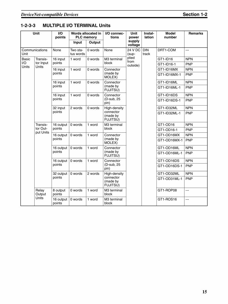
1-2-3-3 MULTIPLE I/O TERMINAL Units
Unit I/O points
Words allocated in PLC memory
I/O connec-tions
Unit power supply voltage
Instal-lation
Modelnumber
Remarks
Input Output
Communications Unit
None Two sta-tus words
0 words None 24 V DC(sup-plied from outside)
DIN track
DRT1-COM ---
Basic I/O Units
Transis-tor Input Units
16 input points
1 word 0 words M3 terminal block
GT1-ID16 NPN
GT1-ID16-1 PNP
16 input points
1 word 0 words Connector (made by MOLEX)
GT1-ID16MX NPN
GT1-ID16MX-1 PNP
16 input points
1 word 0 words Connector (made by FUJITSU)
GT1-ID16ML NPN
GT1-ID16ML-1 PNP
16 input points
1 word 0 words Connector (D-sub, 25 pin)
GT1-ID16DS NPN
GT1-ID16DS-1 PNP
32 input points
2 words 0 words High-density connector (made by FUJITSU)
GT1-ID32ML NPN
GT1-ID32ML-1 PNP
Transis-tor Out-put Units
16 output points
0 words 1 word M3 terminal block
GT1-OD16 NPN
GT1-OD16-1 PNP
16 output points
0 words 1 word Connector (made by MOLEX)
GT1-OD16MX NPN
GT1-OD16MX-1 PNP
16 output points
0 words 1 word Connector (made by FUJITSU)
GT1-OD16ML NPN
GT1-OD16ML-1 PNP
16 output points
0 words 1 word Connector (D-sub, 25 pin)
GT1-OD16DS NPN
GT1-OD16DS-1 PNP
32 output points
0 words 2 words High-density connector (made by FUJITSU)
GT1-OD32ML NPN
GT1-OD31ML-1 PNP
Relay Output Units
8 output points
0 words 1 word M3 terminal block
GT1-ROP08 ---
16 output points
0 words 1 word M3 terminal block
GT1-ROS16 ---
15

DeviceNet-compatible Devices Section 1-2
Note The Analog Input Units, Analog Output Units, Temperature Input Units, andCounter Units belong to a group called Special I/O Units. The front-panel indi-cators and other parts of Special I/O Units differ from those of other I/O Units.
One I/O Unit Connecting Cable (cable length 40 mm) is included with each I/OUnit. One end connector is attached to the Communications Unit.
I/O Unit Connecting Cables with a cable lengths of 0.1, 0.3, 0.4, 0.6, and 1 m(GCN1-010/030/040/060/100) are sold separately (see below).
Special I/O Units(See note.)
Analog Input Units
4 inputs 4 words 0 words M3 terminal block
24 V DC (sup-plied from outside)
DIN track
GT1-AD04 Inputs: 4 to 20 mA, 0 to 20 mA, 0 to 5 V, 1 to 5 V, 0 to 10 V, –10 to 10 V
8 inputs 8 words 0 words Connector (made by MOLEX)
GT1-AD08MX
Analog Output Units
4 outputs 0 words 4 words M3 terminal block
GT1-DA04 Outputs: 4 to 20 mA,0 to 5 V, 1 to 5 V, 0 to 10 V, –10 to 10 V
4 outputs 0 words 4 words Connector (made by MOLEX)
GT1-DA04MX Outputs: 0 to 5 V, 1 to 5 V, 0 to 10 V, –10 to 10 V
Tempera-ture Input Unit
4 inputs 4 or 8 words (varies with data format)
0 words M3 terminal block
GT1-TS04T Sensor types: R, S, K, J, T, B, L
GT1-TS04P Sensor types: Pt100, JPt100
Counter Unit
1 input 3 words 3 words M3 terminal block
GT1-CT01 1 external input2 external outputs
Unit I/O points
Words allocated in PLC memory
I/O connec-tions
Unit power supply voltage
Instal-lation
Modelnumber
Remarks
Input Output
0.1 m/0.3 m/0.4 m/0.6 m/1 m
16

Communications Specifications Section 1-3
1-2-4 DeviceNet ConfiguratorThe Configurator is a software configuration tool for the DeviceNet network.The Configurator can be used to set parameters (the scan list) and monitoroperation in OMRON Master Units. The Configurator can also be used to setparameters in OMRON and other companies’ Slaves.
Note The following Boards and Cards can be used.
1-3 Communications Specifications
Note 1. Terminators are required at both ends of trunk line.
2. Indicates the maximum network length when thick cables are used. Re-duce the network length to 100 m max. when using thin cables.
Product name Model Components Network connection to computer
Applicable computer
OS
DeviceNet Configura-tor (Ver. 2)
WS02-CFDC1-J Installation disk (CD-ROM)
Any of the following:
• Through an Ether-net Unit
• Serial connection• Dedicated PCI
Board• PCMCIA Card
(See the table below.)
IBM PC/AT or compatible
Windows 95, 98, Me, NT4.0, 2000, or XP
Model Components Applicable computer
OS
3G8F7-DRM21 Dedicated PCI Board (Configurator not included.) IBM PC/AT or com-patible
Windows 95, 98, Me, NT 4.0, 2000, or XP
3G8E2-DRM21-V1 Dedicated PCMCIA Card with DeviceNet Configura-tor
Windows 98, Me, NT 4.0, 2000, or XP
Item Specifications
Communications protocol
DeviceNet
Connection meth-ods (See note 1.)
Multi-drop and T-branch connections can be combined (for trunk and branch lines)
Baud rate 500 Kbps, 250 Kbps, or 125 Kbps
Communications media
Special 5-wire cables (2 signal lines, 2 power lines, 1 shield line)Special 4-wire flat cables (2 signal lines, 2 power lines)
Communications distances for spe-cial 5-wire cables
Baud rate Network length
Branch line length
Total branch line length
500 kbps 100 m max. 6 m max. 39 m max.
250 kbps 250 m max. (See note 2.)
6 m max. 78 m max.
125 kbps 500 m max. (See note 2.)
6 m max. 156 m max.
Communications distances for spe-cial 4-wire flat cables
Baud rate Network length
Branch line length
Total branch line length
500 kbps 75 m max. 6 m max. 35 m max.
250 kbps 150 m max. 6 m max. 48 m max.
125 kbps 265 m max. 6 m max. 135 m max.
Communications power supply
24 V DC supplied externally
Max. number of nodes
64 nodes (including Masters, Slaves, and Configurator)
17

Basic Operating Procedures Section 1-4
1-4 Basic Operating Procedures
1-4-1 DeviceNet Network Configuration and Wiring1,2,3... 1. Determine the Baud Rate Required for the Application
Refer to the section on communications timing in the Master Unit Manual(see below) to determine the appropriate responsiveness and baud rate foryour application.
• CS/CJ Series DeviceNet Operation Manual (W380)
• CVM1/CV DeviceNet Master Unit,C200HX/HG/HE DeviceNet Master Unit Operation Manual (W379)
• DeviceNet PCI Board Operation Manual (W381)
2. Determine the Cable Layout and Cable Lengths to All Nodes
Verify that the planned configuration is within the network configurationspecifications.
• Refer to 2-1 Network Configuration Overview for details on the networkconfiguration.
• Refer to 2-2 Network Configuration for configuration precautions.
3. Determine the Communications Power Supply Method
When planning the communications power supply layout, verify that thevoltage drop over the communications cables is within specifications.
• Refer to SECTION 3 Communications Power Supply Methods for de-tails.
• In particular, refer to 3-2-1 Communications Power Supply for a flow-chart that will guide you through the selection process.
4. Select the Required Devices
• Refer to the device manuals when making arrangements for the Mas-ters, Slaves, and the Configurator.
• Refer to 2-3 Cables, Connectors, and Related Devices for details onother related devices.
5. Purchase the Required Equipment
6. Construct the Network
Construct the network using recommended wiring and noise-control tech-niques.
• Refer to 2-4 Wiring Methods for details on wiring.
• Refer to 2-5 Minimizing Noise in the Network for details on noise-con-trol techniques.
• Refer to 2-2 Network Configuration the Network Configuration for otherprecautions.
1-4-2 Network Start-up Procedure
Turn ON the communications power supply.
Turn ON the Slave power supply.
Turn ON the PLC (Master Unit) power supply.
Operate the network.
18

Basic Operating Procedures Section 1-4
Note 1. All three power supplies can be turned ON simultaneously. It is also ac-ceptable to turn ON the communications and Slave power supplies or theSlave and PLC power supplies simultaneously.
2. Slaves may not be recognized if the communications power supply isturned ON after the Slave power supply.
3. Always operate the network with the scan list enabled in the Master Unit.When the scan list is enabled, the user can check whether Slaves are par-ticipating in the network from the PLC and verify that the DeviceNet net-work is communicating normally.
19

Basic Operating Procedures Section 1-4
20

SECTION 2Network Configuration and Wiring
This section explains how to plan the DeviceNet Network configuration and wire the Network.
2-1 Network Configuration Overview. . . . . . . . . . . . . . . . . . . . . . . . . . . . . . . . . . 22
2-1-1 Network Configuration . . . . . . . . . . . . . . . . . . . . . . . . . . . . . . . . . . . 22
2-1-2 Example Network Configuration . . . . . . . . . . . . . . . . . . . . . . . . . . . 25
2-1-3 Network Configuration Restrictions. . . . . . . . . . . . . . . . . . . . . . . . . 26
2-1-4 Connections . . . . . . . . . . . . . . . . . . . . . . . . . . . . . . . . . . . . . . . . . . . 28
2-1-5 Detailed Connection Patterns . . . . . . . . . . . . . . . . . . . . . . . . . . . . . . 30
2-2 Network Configuration . . . . . . . . . . . . . . . . . . . . . . . . . . . . . . . . . . . . . . . . . . 32
2-2-1 Compatible Cables . . . . . . . . . . . . . . . . . . . . . . . . . . . . . . . . . . . . . . 32
2-2-2 Trunk Lines and Branch Lines . . . . . . . . . . . . . . . . . . . . . . . . . . . . . 33
2-2-3 Proper Cable Usage . . . . . . . . . . . . . . . . . . . . . . . . . . . . . . . . . . . . . 37
2-2-4 Determining the Location of the Master. . . . . . . . . . . . . . . . . . . . . . 39
2-2-5 T-branch Tap Connections . . . . . . . . . . . . . . . . . . . . . . . . . . . . . . . . 40
2-2-6 Connecting Devices other than DeviceNet Products . . . . . . . . . . . . 40
2-2-7 Connecting Terminators (Terminating Resistors). . . . . . . . . . . . . . . 40
2-2-8 Using Crimp Terminals. . . . . . . . . . . . . . . . . . . . . . . . . . . . . . . . . . . 41
2-2-9 Sharing the Communications and Internal Circuit Power Supply . . 41
2-2-10 Grounding Methods . . . . . . . . . . . . . . . . . . . . . . . . . . . . . . . . . . . . . 42
2-2-11 Allocating Node Numbers . . . . . . . . . . . . . . . . . . . . . . . . . . . . . . . . 43
2-3 Cables, Connectors, and Related Devices. . . . . . . . . . . . . . . . . . . . . . . . . . . . 43
2-3-1 Communications Cables . . . . . . . . . . . . . . . . . . . . . . . . . . . . . . . . . . 43
2-3-2 Connectors for Node Connections . . . . . . . . . . . . . . . . . . . . . . . . . . 48
2-3-3 Screwdrivers for Connector Screws . . . . . . . . . . . . . . . . . . . . . . . . . 52
2-3-4 T-branch Taps . . . . . . . . . . . . . . . . . . . . . . . . . . . . . . . . . . . . . . . . . . 52
2-3-5 Shielded T-branch Connectors . . . . . . . . . . . . . . . . . . . . . . . . . . . . . 57
2-3-7 Power Supply Tap . . . . . . . . . . . . . . . . . . . . . . . . . . . . . . . . . . . . . . . 59
2-3-8 Terminating Resistors . . . . . . . . . . . . . . . . . . . . . . . . . . . . . . . . . . . . 60
2-3-9 Communications Power Supply . . . . . . . . . . . . . . . . . . . . . . . . . . . . 61
2-4 Wiring Methods. . . . . . . . . . . . . . . . . . . . . . . . . . . . . . . . . . . . . . . . . . . . . . . . 62
2-4-1 Wiring and Installing Standard Connectors . . . . . . . . . . . . . . . . . . . 62
2-4-2 Attaching Flat Cable Connectors . . . . . . . . . . . . . . . . . . . . . . . . . . . 67
2-4-3 Attaching Shielded Connectors . . . . . . . . . . . . . . . . . . . . . . . . . . . . 68
2-4-4 Connecting to T-branch Taps and Nodes . . . . . . . . . . . . . . . . . . . . . 69
2-4-5 Flat Cable I (Standard) . . . . . . . . . . . . . . . . . . . . . . . . . . . . . . . . . . . 70
2-4-6 Connecting Shielded (Environment-resistive) Cables . . . . . . . . . . . 76
2-4-7 Wiring the Communications Power Supply . . . . . . . . . . . . . . . . . . . 76
2-4-8 Connecting the Terminating Resistors (Terminators) . . . . . . . . . . . . 78
2-4-9 Grounding the Network . . . . . . . . . . . . . . . . . . . . . . . . . . . . . . . . . . 80
2-5 Minimizing Noise in the Network. . . . . . . . . . . . . . . . . . . . . . . . . . . . . . . . . . 82
2-5-1 Precautions to Prevent Noise . . . . . . . . . . . . . . . . . . . . . . . . . . . . . . 82
2-5-2 Correcting Malfunctions due to Noise . . . . . . . . . . . . . . . . . . . . . . . 84
2-6 Operational Checklist . . . . . . . . . . . . . . . . . . . . . . . . . . . . . . . . . . . . . . . . . . . 85
21

Network Configuration Overview Section 2-1
2-1 Network Configuration Overview
2-1-1 Network ConfigurationThe DeviceNet Network can be configured as shown in the following dia-grams.
Network with General-purpose Slaves Only
Network with General-purpose and Environment-resistive Slaves
T T TT
M
M
T
M
M M
T
24 VDC
Connect terminators at both ends of the trunk line. Ground to
100 Ω or less.Communications power supply
Use DeviceNet cable.
Connect terminators at both ends of the trunk line.
Use DeviceNet cable.
Node Node Node Node
Node
Node Node
Node
Node
Node
T-branch Tap
T-branch Tap
T-branch Tap
T-branch Tap
T-branch Tap
T-branch TapBranch line
Trunk line Trunk lineTrunk line
Trunk line
Trunk line
Trunk line
Power Supply Tap or T-branch Tap
Use DeviceNet cable for the trunk lines and branch lines.
T: T-branch methodM: Multi-drop method
Branch line
Branch line
Branch line
Branch line
Branch line
Branch line
T T TT
M
M
T
M
TT
24 VDC
Connect terminators at both ends of the trunk line.
Ground to 100 Ω or less.
Use DeviceNet cable.
Node Node
T-branch Tap
T-branch Tap
Trunk line Trunk line
Branch line
Use DeviceNet cable.
Communications power supply
Node
NodeNode
Node
Node
T-branch Tap
T-branch Tap
T-branch Tap
Power Supply Tap or T-branch Tap
Use DeviceNet cable for the trunk lines and branch lines. (Use thin cable with Environment-resistive Slaves.)
T: T-branch methodM: Multi-drop method
Branch line
Branch line
Branch line
Branch line
Branch line
Branch line
Environment-resistive Slave
Environment-resistive Slave
Environment-resistive Slave
Connect terminators at both ends of the trunk line.
T-branch TapConnector with terminator
Branch line
Branch line
T-branch Tap
T-branch Connector
22
Network Configuration Overview Section 2-1
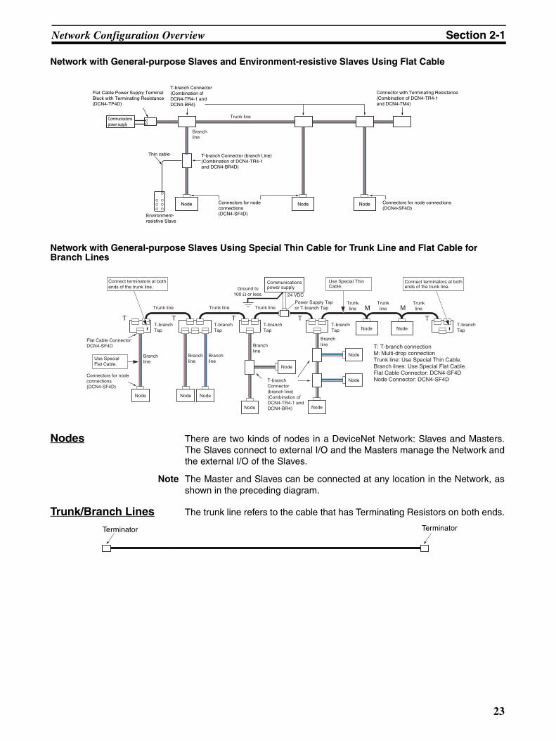
Network with General-purpose Slaves and Environment-resistive Slaves Using Flat Cable
Network with General-purpose Slaves Using Special Thin Cable for Trunk Line and Flat Cable for Branch Lines
Nodes There are two kinds of nodes in a DeviceNet Network: Slaves and Masters.The Slaves connect to external I/O and the Masters manage the Network andthe external I/O of the Slaves.
Note The Master and Slaves can be connected at any location in the Network, asshown in the preceding diagram.
Trunk/Branch Lines The trunk line refers to the cable that has Terminating Resistors on both ends.
NodeNode Node
Communicationspower supply
T-branch Connector (Combination of DCN4-TR4-1 and DCN4-BR4)
T-branch Connector (branch Line)(Combination of DCN4-TR4-1 and DCN4-BR4D)
Connectors for node connections(DCN4-SF4D)
Connectors for node connections(DCN4-SF4D)
Connector with Terminating Resistance (Combination of DCN4-TR4-1 and DCN4-TM4)
Environment-resistive Slave
Thin cable
Branchline
Trunk line
Flat Cable Power Supply Terminal Block with Terminating Resistance (DCN4-TP4D)
Node Node Node
Node
Node
Branchline
Branchline
Branchline
Branchline
T-branchTap
T-branchTap
T-branchTap
T-branchTap
Branchline
T-branchTap
Trunk line Trunk line Trunk lineTrunkline
Trunkline
Trunkline
Node Node
T T TT
M M
T
Use Special Flat Cable.
Connect terminators at both ends of the trunk line.
Power Supply Tap or T-branch Tap
24 VDC
Connect terminators at bothends of the trunk line.
T: T-branch connectionM: Multi-drop connectionTrunk line: Use Special Thin Cable.Branch lines: Use Special Flat Cable.Flat Cable Connector: DCN4-SF4DNode Connector: DCN4-SF4D
Ground to100 Ω or less.
Flat Cable Connector: DCN4-SF4D
Connectors for node connections(DCN4-SF4D)
T-branch Connector (branch line)(Combination of DCN4-TR4-1 and DCN4-BR4)
Node
Node
Node
Communicationspower supply
Use Special Thin Cable.
Terminator Terminator
23

Network Configuration Overview Section 2-1
The cables branching from the trunk line are known as branch lines.
DeviceNet cables (Special Thin/Thick Cables and Special Flat Cables) areused for both the trunk and branch lines in DeviceNet communications. Spe-cial Thin/Thick Cables include Special Thin Cables and Special Thick Cables.
Note With Environment-resistive Slaves (Slaves with a round connector), specialOMRON cable with a shielded, waterproof connector is used for both thetrunk and branch lines.
Terminating Resistors (Terminators)
Always connect Terminating Resistors at both ends of the network to reducesignal reflection and stabilize communications. The cable that stretches fromone terminator to the other is the trunk line. Determine which cable will be thetrunk line based on the network’s configuration.
There are two main kinds of Terminating Resistors available, one for the T-branch Tap/Power Supply Tap and one for a Terminal Block. There are alsoconnectors with terminating resistance (male and female) that connect to theShielded T-branch Connector used with Environment-resistive Slaves.
Note When using a Terminal-block type Terminating Resistor, a DeviceNet cablemust be used for the cable connecting the Terminating Resistor.
Connection Methods Two methods can be used to connect DeviceNet nodes: The T-branch methodand the multi-drop method. With the T-branch method, the node is connectedto a branch line created with a T-branch Tap or Shielded T-branch Connector.
Terminator Terminator
T-branch Taps
All are branch lines.
There is no limit on the number of T-branch Taps. Only the total length of the branch lines is limited.
Trunk line
Trunk line
24
Network Configuration Overview Section 2-1
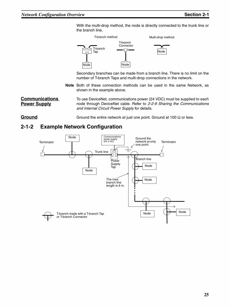
With the multi-drop method, the node is directly connected to the trunk line orthe branch line.
Secondary branches can be made from a branch line. There is no limit on thenumber of T-branch Taps and multi-drop connections in the network.
Note Both of these connection methods can be used in the same Network, asshown in the example above.
Communications Power Supply
To use DeviceNet, communications power (24 VDC) must be supplied to eachnode through DeviceNet cable. Refer to 2-2-9 Sharing the Communicationsand Internal Circuit Power Supply for details.
Ground Ground the entire network at just one point. Ground at 100 Ω or less.
2-1-2 Example Network Configuration
T-branch method Multi-drop method
T-branch Tap
T-branch Connector
Node Node
Node
Terminator Terminator
Node
Node
Node
Node
Node Node
Communications power supply(24 V DC)
Trunk line
Branch linePower Supply Tap
Ground the network at only one point.
The max. branch line length is 6 m.
T-branch made with a T-branch Tap or T-branch Connector
25
Network Configuration Overview Section 2-1
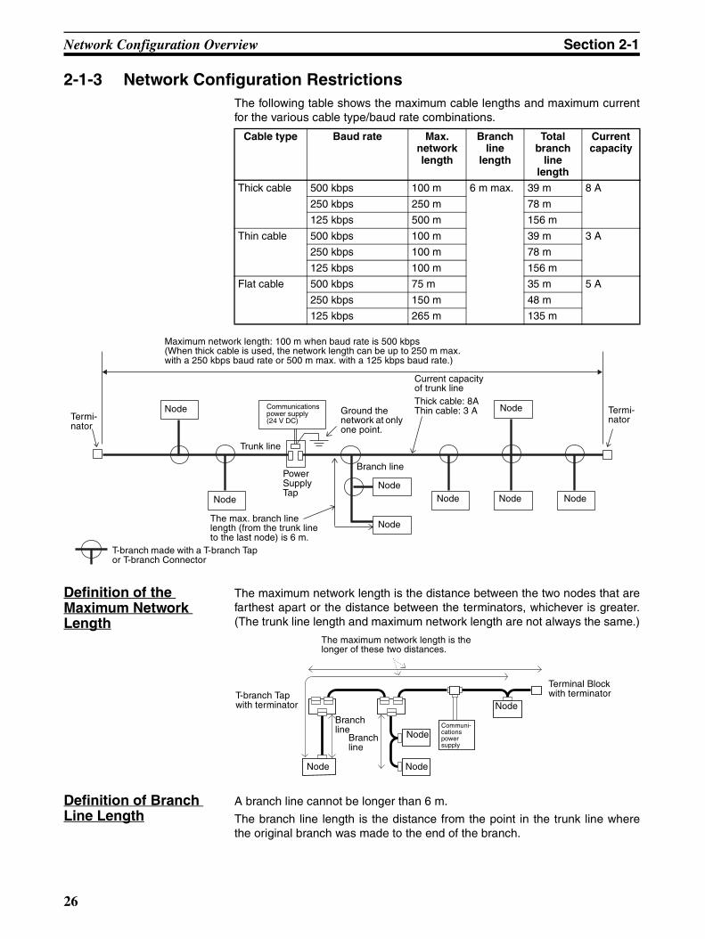
2-1-3 Network Configuration RestrictionsThe following table shows the maximum cable lengths and maximum currentfor the various cable type/baud rate combinations.
Definition of the Maximum Network Length
The maximum network length is the distance between the two nodes that arefarthest apart or the distance between the terminators, whichever is greater.(The trunk line length and maximum network length are not always the same.)
Definition of Branch Line Length
A branch line cannot be longer than 6 m.
The branch line length is the distance from the point in the trunk line wherethe original branch was made to the end of the branch.
Cable type Baud rate Max. network length
Branch line
length
Total branch
line length
Current capacity
Thick cable 500 kbps 100 m 6 m max. 39 m 8 A
250 kbps 250 m 78 m
125 kbps 500 m 156 m
Thin cable 500 kbps 100 m 39 m 3 A
250 kbps 100 m 78 m
125 kbps 100 m 156 m
Flat cable 500 kbps 75 m 35 m 5 A
250 kbps 150 m 48 m
125 kbps 265 m 135 m
Termi-nator
Termi-nator
Node
Node Communications power supply(24 V DC)
Trunk line
Power Supply Tap
Ground the network at only one point.
The max. branch line length (from the trunk line to the last node) is 6 m.
T-branch made with a T-branch Tap or T-branch Connector
Node
Node
Node Node Node
Node
Current capacity of trunk lineThick cable: 8AThin cable: 3 A
Maximum network length: 100 m when baud rate is 500 kbps(When thick cable is used, the network length can be up to 250 m max. with a 250 kbps baud rate or 500 m max. with a 125 kbps baud rate.)
Branch line
The maximum network length is the longer of these two distances.
Communi-cations power supply
Node
Node
Branch line Node
Node
Branch line
Terminal Block with terminatorT-branch Tap
with terminator
26

Network Configuration Overview Section 2-1
Note The branch line length is not just the distance between T-branch Taps or thedistance from a node to a T-branch Tap on the branch line; it is the total dis-tance from the trunk line to the end of the branch.
Definition of Total Branch Line Length
The total branch line length is the sum of all branch lines in the network.
In the example above, the total branch line length is 40 m. The maximum totalbranch line length is 39 m for 500-kbps communications, so a baud rate of250 kbps or 125 kbps must be used in this network.
(Total branch line length) = (1) + (2) + (3) + (4) + (5) + (6) + (7) + (8) + (9) +(10) + (11) + (12) + (13)
= 2 + 3 + 1 + 2 + 2 + 6 + 2 + 2 + 1 + 1 + 6 + 6 + 6
= 40 m
Current Capacities of the Cables
The current capacity of the trunk line is 8 A when a Thick Cable is used, 3 Awhen a Thin Cable is used, and 5 A when a Special Flat Cable is used. Toestimate the current through the trunk line, add up the current consumption ofall the nodes in each direction from the communications power supply. Thetotal current consumption must be no more than 8 A when a Thick Cable isused, 3 A when a Thin Cable is used, and 5 A when a Special Flat Cable isused.
With branch lines, the current carrying capacity of the branch line is inverselyproportional to the length of the line. The current capacity of a branch line is4.57/L (A) where L is the length of the branch line (m). Verify that the total cur-
4 m
1 m 1 m
1 m2 m
Branch line (6 m max.)
Node
T-branch Tap
Node 1
Example 1 Example 2
Node 2
Node 3 Node 4
Trunk line
Trunk lineT-branch Tap A
These lengths are not branch line lengths.
Branch line length
T-branch Tap A to Node 1: 5 mT-branch Tap A to Node 2: 6 mT-branch Tap A to Node 3: 5 mT-branch Tap A to Node 4: 6 mAll branch lines are 6 m or less.
(5) 2 m(3) 1 m
(1) 2 m
(4) 2 m
(2) 3 m (6) 6 m(7) 2 m
(8) 2 m
(10) 1 m
(9)1 m
(11) 6 m (12) 6 m (13) 6 m
Terminator
Node
Terminator
Node
Node Node Node Node Node
Node
Node
Node
NodeTotal branch line length is the total of all of these branch lines.(40 m in this case)
27
Network Configuration Overview Section 2-1
rent consumption of the nodes in the branch is less than 4.57/L or 3 A, which-ever is lower.
Refer to SECTION 3 Communications Power Supply Methods for moredetails.
Note 1. Always use DeviceNet cables.
2. Always connect terminators at both ends of the trunk line.
3. Do not install devices other than DeviceNet devices (e.g., a lightning arres-tor) in the communications line. Devices other than DeviceNet-compatibledevices can cause effects such as signal reflection and interfere with De-viceNet communications.
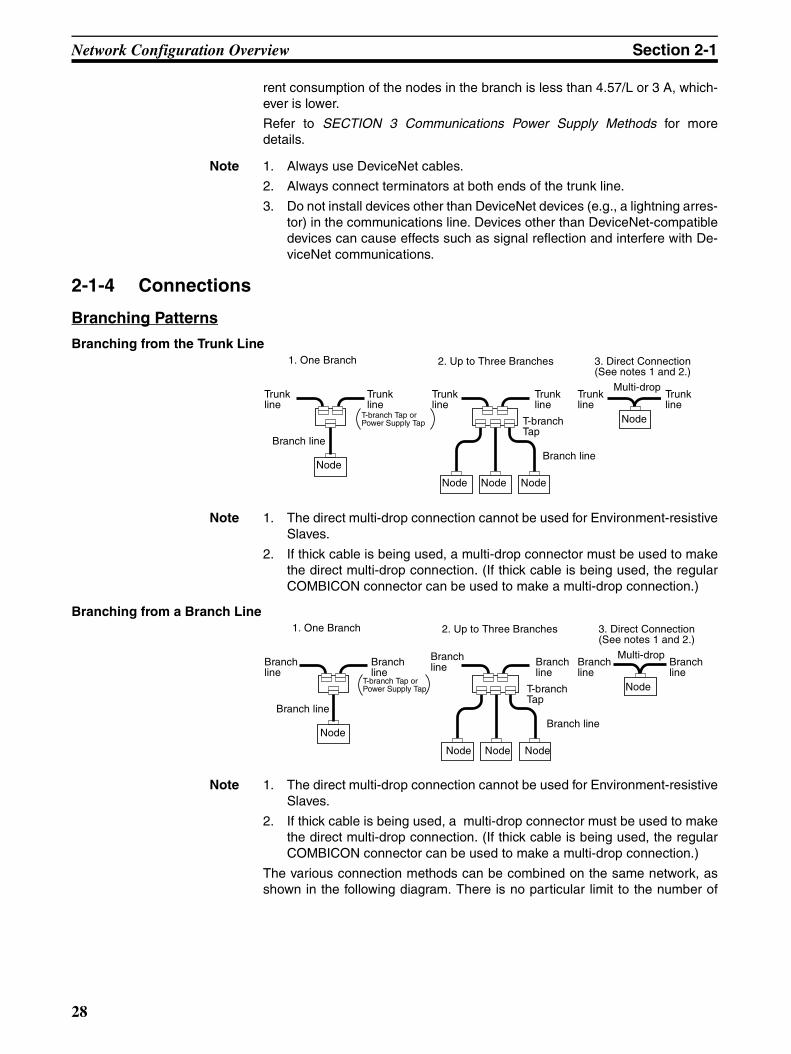
2-1-4 Connections
Branching Patterns
Branching from the Trunk Line
Note 1. The direct multi-drop connection cannot be used for Environment-resistiveSlaves.
2. If thick cable is being used, a multi-drop connector must be used to makethe direct multi-drop connection. (If thick cable is being used, the regularCOMBICON connector can be used to make a multi-drop connection.)
Branching from a Branch Line
Note 1. The direct multi-drop connection cannot be used for Environment-resistiveSlaves.
2. If thick cable is being used, a multi-drop connector must be used to makethe direct multi-drop connection. (If thick cable is being used, the regularCOMBICON connector can be used to make a multi-drop connection.)
The various connection methods can be combined on the same network, asshown in the following diagram. There is no particular limit to the number of
1. One Branch 2. Up to Three Branches 3. Direct Connection(See notes 1 and 2.)
Trunk line
Trunk line
T-branch Tap or Power Supply Tap T-branch
Tap
Node
Node Node Node
Node
Branch lineBranch line
Multi-dropTrunk line
Trunk line
Trunk line
Trunk line
1. One Branch 2. Up to Three Branches 3. Direct Connection(See notes 1 and 2.)
Branch line
Branch line
T-branch Tap or Power Supply Tap T-branch
Tap
Node
Node Node Node
Node
Branch lineBranch line
Multi-dropBranch line Branch
lineBranch line
Branch line
28

Network Configuration Overview Section 2-1
nodes that can be connected onto a single branch line, except for the limit onthe total number of nodes (63 max.) in the network.
Note Environment-resistive Slaves cannot be connected directly to the trunk linewith the multi-drop method. General-purpose and Special Slaves can be con-nected directly to the trunk line with the multi-drop method, but it is easier toconnect a node to a branch line.
24 VDC
Communications power supply
Branch line
Node
T-branch Tap with terminator
T-branch Tap with terminator
Branch line Branch line
Trunk line Trunk line
T-branch Tap or Power Supply Tap
NodeNode NodeNode
Node
NodeNode
Node
Node
29

Network Configuration Overview Section 2-1
2-1-5 Detailed Connection Patterns
Branches
T-branch Method
Note The cables with a shielded connector on one or both ends have a round com-munications connector on one or both ends.
Connection pattern Connection method
Or
Or
Trunk line
Trunk line
T-branch Tap or Power Supply Tap
Node
Branch line
Branch line
Branch line
T-branch Tap or Power Supply Tap
Node
Branch line
General-purpose Slaves, Special Slaves, and Masters
Environment-resistive Slaves
Thick cable, thin cable, or cable with shielded connector on one end
T-branch Tap (DCN1-1C/2C/2R)
Standard Connector provided with T-branch TapThick or thin cable
COMBICON Connector
General-purpose Slave, Special Slave, or Master Environment-resistive Slave
Thick cable, thin cable, or cable with shielded connector on one end
T-branch Tap (DCN1-1C/2C/2R)
Standard Connector provided with T-branch TapDCA1-5CN@@F1 Thin Cable with attached round, shielded connector
FemaleMale
General-purpose Slave, Special Slave, or Master Environment-resistive Slave
DCA1-5CN@@H1 Thin Cable with round, shielded connector on one end
Female Male
COMBICON Connector
Shielded T-branch Connector
Cable with shielded connector on one end or both ends
DCA1-5CN@@W1 Thin Cable with round, shielded connectors on both ends
Shielded T-branch Connector
Cable with shielded connector on one end or both ends
Male
Male
Female
Female
Standard Connector provided with T-branch Tap
Standard Connector provided with T-branch Tap
T-branch Tap
Node Node Node
Branch line
Trunk line
Trunk line
T-branch Tap
Node Node Node
Branch line
Branch line
Branch line
General-purpose Slaves, Special Slaves, and Masters
Environment-resistive Slaves
Thick cable, thin cable, or cable with shielded connector on one end
T-branch Tap (DCN1-3C/4C/4R)
Thick cable, thin cable, or cable with shielded connector on one end
T-branch Tap (DCN1-3C/4C/4R)
Environment-resistive Slaves can be connected as well. General-purpose Slaves can
be connected as well.Thick or thin cable
COMBICON Connector
General-purpose Slave, Special Slave, or Master Environment-resistive Slave
DCA1-5CN@@F1 Thin Cable with attached round, shielded connector
FemaleMale
30
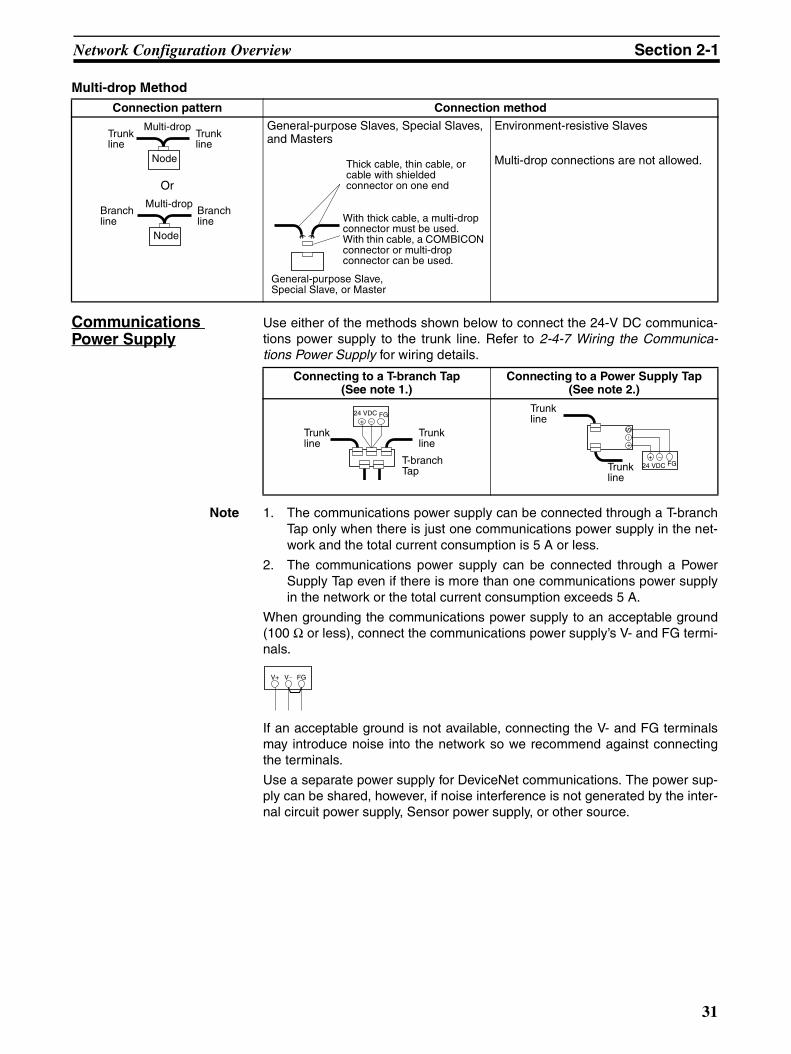
Network Configuration Overview Section 2-1
Multi-drop Method
Communications Power Supply
Use either of the methods shown below to connect the 24-V DC communica-tions power supply to the trunk line. Refer to 2-4-7 Wiring the Communica-tions Power Supply for wiring details.
Note 1. The communications power supply can be connected through a T-branchTap only when there is just one communications power supply in the net-work and the total current consumption is 5 A or less.
2. The communications power supply can be connected through a PowerSupply Tap even if there is more than one communications power supplyin the network or the total current consumption exceeds 5 A.
When grounding the communications power supply to an acceptable ground(100 Ω or less), connect the communications power supply’s V- and FG termi-nals.
If an acceptable ground is not available, connecting the V- and FG terminalsmay introduce noise into the network so we recommend against connectingthe terminals.
Use a separate power supply for DeviceNet communications. The power sup-ply can be shared, however, if noise interference is not generated by the inter-nal circuit power supply, Sensor power supply, or other source.
Connection pattern Connection method
Or
General-purpose Slaves, Special Slaves, and Masters
Environment-resistive Slaves
Multi-drop connections are not allowed.Node
Multi-dropTrunk line
Trunk line
Node
Multi-dropBranch line
Branch line
General-purpose Slave, Special Slave, or Master
Thick cable, thin cable, or cable with shielded connector on one end
With thick cable, a multi-drop connector must be used.With thin cable, a COMBICON connector or multi-drop connector can be used.
Connecting to a T-branch Tap(See note 1.)
Connecting to a Power Supply Tap(See note 2.)
+ −24 VDC FG
T-branch Tap
Trunk line
Trunk line
+ −24 VDC
S−
+
FG
Trunk line
Trunk line
FGV+ V−
31
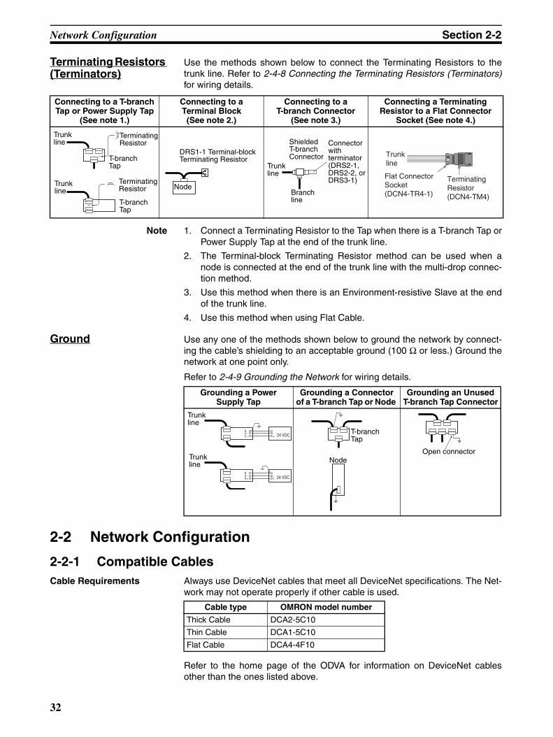
Network Configuration Section 2-2
Terminating Resistors (Terminators)
Use the methods shown below to connect the Terminating Resistors to thetrunk line. Refer to 2-4-8 Connecting the Terminating Resistors (Terminators)for wiring details.
Note 1. Connect a Terminating Resistor to the Tap when there is a T-branch Tap orPower Supply Tap at the end of the trunk line.
2. The Terminal-block Terminating Resistor method can be used when anode is connected at the end of the trunk line with the multi-drop connec-tion method.
3. Use this method when there is an Environment-resistive Slave at the endof the trunk line.
4. Use this method when using Flat Cable.
Ground Use any one of the methods shown below to ground the network by connect-ing the cable’s shielding to an acceptable ground (100 Ω or less.) Ground thenetwork at one point only.
Refer to 2-4-9 Grounding the Network for wiring details.
2-2 Network Configuration
2-2-1 Compatible CablesCable Requirements Always use DeviceNet cables that meet all DeviceNet specifications. The Net-
work may not operate properly if other cable is used.
Refer to the home page of the ODVA for information on DeviceNet cablesother than the ones listed above.
Connecting to a T-branch Tap or Power Supply Tap
(See note 1.)
Connecting to a Terminal Block
(See note 2.)
Connecting to a T-branch Connector
(See note 3.)
Connecting a Terminating Resistor to a Flat Connector
Socket (See note 4.)
T-branch Tap
Trunk line
Trunk line
Terminating Resistor
Terminating Resistor
T-branch Tap
DRS1-1 Terminal-block Terminating Resistor
Node
Trunk line
ShieldedT-branch Connector
Connector with terminator (DRS2-1, DRS2-2, or DRS3-1)
Branch line
Terminating Resistor(DCN4-TM4)
Trunkline
Flat Connector Socket(DCN4-TR4-1)
Grounding a Power Supply Tap
Grounding a Connector of a T-branch Tap or Node
Grounding an Unused T-branch Tap Connector
SV− −
+
SV−V+
−+
24 VDC
24 VDC
Trunk line
Trunk line
T-branch Tap
NodeOpen connector
Cable type OMRON model number
Thick Cable DCA2-5C10
Thin Cable DCA1-5C10
Flat Cable DCA4-4F10
32
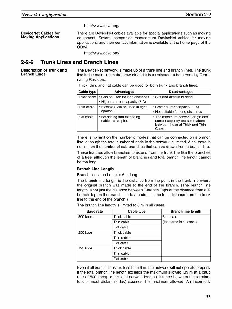
Network Configuration Section 2-2
http://www.odva.org/
DeviceNet Cables for Moving Applications
There are DeviceNet cables available for special applications such as movingequipment. Several companies manufacture DeviceNet cables for movingapplications and their contact information is available at the home page of theODVA.
http://www.odva.org/
2-2-2 Trunk Lines and Branch LinesDescription of Trunk and Branch Lines
The DeviceNet network is made up of a trunk line and branch lines. The trunkline is the main line in the network and it is terminated at both ends by Termi-nating Resistors.
Thick, thin, and flat cable can be used for both trunk and branch lines.
There is no limit on the number of nodes that can be connected on a branchline, although the total number of node in the network is limited. Also, there isno limit on the number of sub-branches that can be drawn from a branch line.
These features allow branches to extend from the trunk line like the branchesof a tree, although the length of branches and total branch line length cannotbe too long.
Branch Line Length
Branch lines can be up to 6 m long.
The branch line length is the distance from the point in the trunk line wherethe original branch was made to the end of the branch. (The branch linelength is not just the distance between T-branch Taps or the distance from a T-branch Tap on the branch line to a node; it is the total distance from the trunkline to the end of the branch.)
The branch line length is limited to 6 m in all cases.
Even if all branch lines are less than 6 m, the network will not operate properlyif the total branch line length exceeds the maximum allowed (39 m at a baudrate of 500 kbps) or the total network length (distance between the termina-tors or most distant nodes) exceeds the maximum allowed. An incorrectly
Cable type Advantages Disadvantages
Thick cable • Can be used for long distances.• Higher current capacity (8 A)
• Stiff and difficult to bend
Thin cable • Flexible (Can be used in tight spaces.)
• Lower current capacity (3 A)• Not suitable for long distances
Flat cable • Branching and extending cables is simpler.
• The maximum network length and current capacity are somewhere between those of Thick and Thin Cable.
Baud rate Cable type Branch line length
500 kbps Thick cable 6 m max.
(the same in all cases)Thin cable
Flat cable
250 kbps Thick cable
Thin cable
Flat cable
125 kbps Thick cable
Thin cable
Flat cable
33

Network Configuration Section 2-2
configured network will have recurring communications errors, such asremote I/O communications errors and transmission timeouts.
Total Branch Line Length
The total branch line length is the sum of the lengths of all branch lines in thenetwork. The maximum total branch line length depends upon the baud rate,as shown in the following table.
• Special Thin/Thick Cable
• Special Flat Cable
Maximum Network Length
The maximum network length is the distance between the two nodes that arefarthest apart or the distance between the terminators, whichever is greater.(The trunk line length and max. network length are not always the same.)
The maximum network length depends upon the baud rate and cable type, asshown in the following table.
• Special Thin/Thick Cable
• Special Flat Cable
Maximum Current Capacity
The maximum current capacity of a line depends on the cable type and thefunction of the line (trunk or branch line). When planning the network configu-ration, consider the type of cable being used, position of each device, andeach device’s current consumption.
Baud rate Total branch line length
500 kbps 39 m max.
250 kbps 78 m max.
125 kbps 156 m max.
Baud rate Total branch line length
500 kbps 35 m max.
250 kbps 48 m max.
125 kbps 135 m max.
Baud rate Cable type Total branch line length
500 kbps Thick cable 100 m
Thin cable
250 kbps Thick cable 250 m
Thin cable 100 m
125 kbps Thick cable 500 m
Thin cable 100 m
Baud rate Total branch line length
500 kbps 75 m max.
250 kbps 150 m max.
125 kbps 265 m max.
34

Network Configuration Section 2-2
• DeviceNet Cable
A Simple Way to Reduce Total Branch Line Length
It can be time-consuming to calculate the total branch line length and fairly dif-ficult to meet the conditions that individual branch lines do not exceed 6 mand the total branch line length does not exceed 39 m (with a baud rate of500 kbps.) A common cause of long branch lines and excessive total branchline length is using a straight trunk line, as shown in the following diagram.
The branch line lengths can be reduced significantly by redirecting the trunkline at each node rather than using a straight trunk line. While this configura-tion reduces branch line lengths, it will increase the maximum network length(distance between the terminators or the nodes that are farthest apart). Verify
Line Cable type Maximum current capacity
Trunk Thick cable 8 A
Thin cable 3 A
Flat cable 5 A
Branch Thick or thin cable 0.75 to 3 AThe current capacity (A) of a branch line is 4.57/L (up to 3 A) where L is the length (m) of the branch line.
Terminator Terminator
PLC Master
Branch line
Network configuration with a straight trunk line
Branch line
Branch line
Branch lines too long
Branch line
Trunk line
Trunk line
Branch line
Branch lineT-branch Tap
35
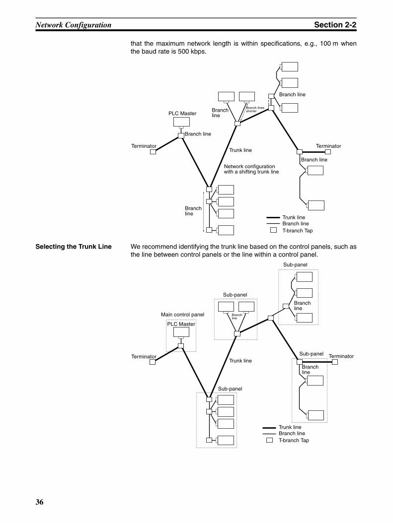
Network Configuration Section 2-2
that the maximum network length is within specifications, e.g., 100 m whenthe baud rate is 500 kbps.
Selecting the Trunk Line We recommend identifying the trunk line based on the control panels, such asthe line between control panels or the line within a control panel.
Terminator Terminator
PLC Master
Network configuration with a shifting trunk line
Branch line
Branch lines shorter
Trunk line
Trunk line
Branch line
Branch lineT-branch Tap
Branch line
Branch line
Branch line
Terminator Terminator
PLC Master
Trunk line
Trunk lineBranch lineT-branch Tap
Branch line
Branch line
Branch line
Main control panel
Sub-panel
Sub-panel
Sub-panel
Sub-panel
36

Network Configuration Section 2-2
2-2-3 Proper Cable UsageThe following table shows the limitations of the thin and thick cables.
Selecting between Thick and Thin Cable
The branch line length and total branch line length limitations are the same forboth thin and thick cables. The cables differ in the following two capabilities.
1,2,3... 1. Maximum network length
With thin cable, the maximum network length is limited to 100 m in all cas-es. At 500 kbps, the maximum network length is the same for both thickand thin cables, so this limitation is not a consideration when the baud rateis 500 kbps.
Thick and thin cable can be used in the same network, but the max. net-work length declines as more thin cable is used. Refer to Combining Thickand Thin Cables on page 37 for the equations used to calculate the max.network length when thick and thin cable are used together.
2. Current capacity
In the trunk line, the cable current capacity (max. current allowed in the ca-ble) is 3 A for thin cable and 8 A for thick cable. Consequently, thick cablecan provide a significantly higher current when the communications powersupply is being supplied through a Power Supply Tap. If thin cable is beingused, the current in any one direction is limited to 3 A regardless of the ca-pacity of the 24 V DC power supply that is connected.
Note The communications power supply can also be supplied through a T-branchTap or T-branch Connector, but the current capacity of a T-branch Tap is 5 A.The current capacity of the thin-cable T-branch Connectors is 3 A and the cur-rent capacity of the thick-cable T-branch Connector is 8 A. Consequently, theconditions for supplying power through a T-branch Tap or thin-cable T-branchConnector are as follows: There can be only one communications power sup-ply in the network and the total current consumption (in both directions) is lim-ited to 5 A for a T-branch Tap or 3 A for a thin-cable T-branch Connector.
Combining Thick and Thin Cables
Thick and thin cable can be combined in the line connecting most distantnodes, but the max. network length will be shorter than it would be with thick
Cable type Baud rate Max. network length
Branch line length
Total branch line length
Current capacity
Thick cable 500 kbps 100 m 6 m max. 39 m 8 A
250 kbps 250 m 78 m
125 kbps 500 m 156 m
Thin cable 500 kbps 100 m 39 m 3 A
250 kbps 100 m 78 m
125 kbps 100 m 156 m
← → ← →
← →
Power Supply Tap
Current 8 A max.
Current 8 A max.
Thick cable
Communications power supply
Power Supply Tap
Current 8 A max.
Current 3 A max.
Thin cable
Communications power supply
Thick cable
Power Supply Tap
Current 3 A max.
Current 3 A max.
Thin cable
Communications power supply
Thin cable
37
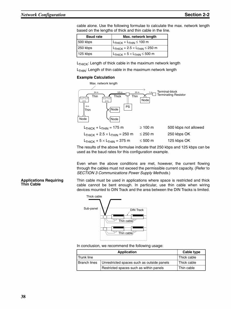
Network Configuration Section 2-2
cable alone. Use the following formulae to calculate the max. network lengthbased on the lengths of thick and thin cable in the line.
LTHICK: Length of thick cable in the maximum network length
LTHIN: Length of thin cable in the maximum network length
Example Calculation
LTHICK + LTHIN = 175 m ≥ 100 m 500 kbps not allowed
LTHICK + 2.5 × LTHIN = 250 m ≤ 250 m 250 kbps OK
LTHICK + 5 × LTHIN = 375 m ≤ 500 m 125 kbps OK
The results of the above formulae indicate that 250 kbps and 125 kbps can beused as the baud rates for this configuration example.
Even when the above conditions are met, however, the current flowingthrough the cables must not exceed the permissible current capacity. (Refer toSECTION 3 Communications Power Supply Methods.)
Applications Requiring Thin Cable
Thin cable must be used in applications where space is restricted and thickcable cannot be bent enough. In particular, use thin cable when wiringdevices mounted to DIN Track and the area between the DIN Tracks is limited.
In conclusion, we recommend the following usage:
Baud rate Max. network length
500 kbps LTHICK + LTHIN ≤ 100 m
250 kbps LTHICK + 2.5 × LTHIN ≤ 250 m
125 kbps LTHICK + 5 × LTHIN ≤ 500 m
6 m
24 m 125 m 20 m 1 m
Max. network length
Terminal-block Terminating Resistor
Node
Node
NodeNode
PS
Thick
Thin
Thin Thin
Application Cable type
Trunk line Thick cable
Branch lines Unrestricted spaces such as outside panels Thick cable
Restricted spaces such as within panels Thin cable
Sub-panel
Thin cable
Thin cable
DIN Track
Thick cable
38

Network Configuration Section 2-2
Proper Distance between Wiring Duct and Node
Allow about 10 cm between the wiring duct and nodes so that the nodes canbe wired without straining the connectors. Communications errors may occurif there isn’t enough slack in the cable and the connectors are pulled out.
Note Do not strip too much insulation and shielding from the cable. Removing toomuch shielding will provide a path for noise to enter the network.
Considerations in Choosing Special Thin/Thick Cable or Special Flat Cable
Using Special Flat Cable makes it easy to extend a branch cable using one-touch connectors, but Special Flat Cable cannot be combined with a trunk lineconsisting of Special Thin/Thick Cable. There are differences between Spe-cial Thin/Thick Cable and Special Flat Cable in terms of maximum networklength, branch line length, and current capacity. For detailed specifications,refer to 2-2-2 Trunk Lines and Branch Lines.
2-2-4 Determining the Location of the MasterIt is not necessary to locate the Master at the end of the network. The Mastercan be located at any node position on the trunk line or a branch line. Configure the network as desired, since there is no restriction on the Master’slocation.
Duct
Incorrect Correct
Duct
NodeNode
Too close Allow about 10 cm.
Trunk line Branch line Application
Flat cable Thick cable Connect to T-branch Tap.
Thin cable Connect using T-branch Connector (DCN4-TR4-1 + DCN4-BR4D).
Flat cable Connect using T-branch Connector (DCN4-TR4-1 + DCN4-BR4).
Thick cable Flat cable Connect to T-branch Tap.
Thin cable Flat cable Connect to T-branch Tap.
PLC Master
Trunk lineBranch lineT-branch Tap
Branch lines
Branch line
Main control panelSub-panel
Sub-panel
Sub-panel
Branch lines
39

Network Configuration Section 2-2
2-2-5 T-branch Tap ConnectionsThe single-branch T-branch Taps (3 connectors) can be used to make abranch from the trunk line or a branch line. It isn’t necessary to connect thepaired connectors to the trunk line. Likewise, there is no restriction on the useof connectors in a three-branch T-branch Tap. The connectors can connect tothe trunk line or branch lines.
Although there is no restriction on the use of connectors in the T-branch Taps,as a rule we recommend using the paired connectors for the trunk line so thatthe trunk line is easy to identify.
2-2-6 Connecting Devices other than DeviceNet ProductsDo not connect devices that are not DeviceNet products because incompati-ble devices can cause signal reflection or attenuation and interfere with nor-mal network communications.
2-2-7 Connecting Terminators (Terminating Resistors)What is a Terminating Resistor?
A Terminating Resistor (commonly known as a terminator) is a resistor con-nected to the end of the trunk line to absorb the signals sent through the net-work, dissipating the signals as heat and preventing them from bouncing backinto the network. A Terminating Resistor is required at each end of the net-work (trunk line).
Note Terminating resistors are not built into DeviceNet devices.
Operation without Terminating Resistors
The DeviceNet network will not function properly without Terminating Resis-tors. Communications errors will occur, such as remote I/O communicationserrors and communications timeouts.
The signals in a DeviceNet network are comparable to surface waves onwater. When a stone is dropped in a bucket of water, circular waves ema-nate from the stone and run into the sides of the bucket and the reflectedwaves interfere with the waves coming from the center. As a result, thewaves from the center become distorted.
The same principle applies to the digital signals in a DeviceNet network.When the digital signals (waves) passing through the network reach theend of the network, the bounce back and interfere with the signals (waves)emanating from the DeviceNet Master (center) of the network.
The Terminating Resistors absorb the digital signals at the ends of the net-work so that they do not bounce back and distort the signals from the Mas-ter.
Operation with Too Many Terminating Resistors
If Terminating Resistors are attached at all T-branch Taps within the network,the digital communications signals will be absorbed midway through the net-work and the network will not function normally. Communications errors willoccur, such as remote I/O communications errors and communications time-outs.
Trunk line
Branch line
Trunk line
Branch line
Trunk line
Trunk line
Trunk line
Branch line
Trunk line
Branch lines
Branch line
Trunk line
Trunk line
Branch line
Both configurations are acceptable.
Both configurations are acceptable.
40

Network Configuration Section 2-2
Checking the Installation of Terminating Resistors
If communications errors occur when setting up the system, it is possible tocheck whether or not the Terminating Resistors are connected properly. TurnOFF the network power supply and use a multimeter to test the resistancebetween any node’s CAN H signal wire (white) and CAN L signal wire (blue).
• A normal resistance reading is 50 to 70 Ω.
• If the resistance is greater than 70 Ω, there may be a broken signal linein the network or one or both Terminating Resistors may be missing.A reading of about 100 Ω indicates that one Terminating Resistor ismissing.A reading of about 300 Ω or higher indicates that both Terminating Re-sistors are missing.
• If the resistance is less than 50 Ω, there may be too many TerminatingResistors (3 or more) in the network.
Note Do not test the resistance while the network is operating. Errors will occur inthe communications data and could cause unexpected problems.
2-2-8 Using Crimp TerminalsWe strongly recommend the use of crimp terminals (solderless pin terminals)on the wires that connect to the communications cable connectors. The fol-lowing problems may occur if crimp terminals are not used.
1. A stray wire strand may contact the adjacent terminal and cause a short.
2. The cable may pull out of the connector.
3. The contact between the wire and connector may be poor.
Refer to 2-4 Wiring Methods for information on recommended crimp termi-nals.
2-2-9 Sharing the Communications and Internal Circuit Power SupplyTo avoid noise problems, it is generally recommended to provide separatecommunications and internal circuit power supplies, but the same power sup-ply can be used for both purposes if necessary.
When a power supply is shared for the communications and internal circuitpower supplies, wire the network as shown in configuration A. Do not use con-figuration B because it will generate more noise than configuration A.
Ω
Multimeter
Use a multimeter to measure the resistance between the signal wires.
Blue (CAN L)White (CAN H)
41

Network Configuration Section 2-2
Configuration A:
Configuration B:
Note The low voltage limit for the internal circuit power supply is higher than the lowvoltage limit for the communications power supply. To meet the voltage speci-fications for the internal circuit power supply, be sure to follow the specifica-tions listed in SECTION 3 Communications Power Supply Methods.
2-2-10 Grounding MethodsProper Grounding Practices
Ground the DeviceNet shield wire to 100 Ω max. at one and only one point inthe network. Grounding more than one point can cause ground loops andnoise in the network.
Generally, the communications power supply’s FG terminal is grounded to100 Ω max. and connected to the V- terminal and the Power Supply Tap’sshield (S) terminal, as shown in example A below. It is also acceptable to con-nect the communications power supply’s FG terminal and the V- terminal andground the network from the Power Supply Tap’s shield (S) terminal, as shownin example B below.
In either case, ground the network as close to the center of the network aspossible.
When there are two or more communications power supplies in the network,determine which power supply is closest to the center of the network. Connect
V− V+ − +24 VDC 24 VDC
V− V+ − +Shared communications and internal circuit power supply
Correct
Communications power supply
Internal circuit power supply
Communications power supply
Internal circuit power supply
Vv V+ − +24 VDC
V− V+ − +24 VDC
Incorrect
Shared communications and internal circuit power supply
Communications power supply
Internal circuit power supply
Communications power supply
Internal circuit power supply
V+CAN H
CAN LV−
V+
V+ V− S
V+ V− FG
CAN H
CAN LV−
V+CAN H
CAN LV−
V+
V+ V− S
V+ V− FG
CAN H
CAN LV−
Power Supply Tap
Example A Example B
Power Supply Tap
Shield (S) Shield (S) DeviceNet cable
Communications power supply
Ground to 100 Ω max.
Ground to 100 Ω max.
Shield (S) Shield (S) DeviceNet cable
Communications power supply
42
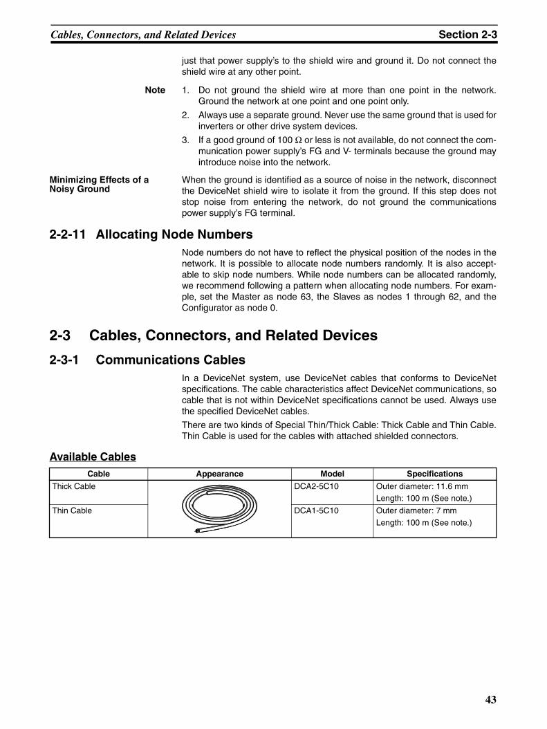
Cables, Connectors, and Related Devices Section 2-3
just that power supply’s to the shield wire and ground it. Do not connect theshield wire at any other point.
Note 1. Do not ground the shield wire at more than one point in the network.Ground the network at one point and one point only.
2. Always use a separate ground. Never use the same ground that is used forinverters or other drive system devices.
3. If a good ground of 100 Ω or less is not available, do not connect the com-munication power supply’s FG and V- terminals because the ground mayintroduce noise into the network.
Minimizing Effects of a Noisy Ground
When the ground is identified as a source of noise in the network, disconnectthe DeviceNet shield wire to isolate it from the ground. If this step does notstop noise from entering the network, do not ground the communicationspower supply’s FG terminal.
2-2-11 Allocating Node NumbersNode numbers do not have to reflect the physical position of the nodes in thenetwork. It is possible to allocate node numbers randomly. It is also accept-able to skip node numbers. While node numbers can be allocated randomly,we recommend following a pattern when allocating node numbers. For exam-ple, set the Master as node 63, the Slaves as nodes 1 through 62, and theConfigurator as node 0.
2-3 Cables, Connectors, and Related Devices
2-3-1 Communications CablesIn a DeviceNet system, use DeviceNet cables that conforms to DeviceNetspecifications. The cable characteristics affect DeviceNet communications, socable that is not within DeviceNet specifications cannot be used. Always usethe specified DeviceNet cables.
There are two kinds of Special Thin/Thick Cable: Thick Cable and Thin Cable.Thin Cable is used for the cables with attached shielded connectors.
Available CablesCable Appearance Model Specifications
Thick Cable DCA2-5C10 Outer diameter: 11.6 mmLength: 100 m (See note.)
Thin Cable DCA1-5C10 Outer diameter: 7 mm
Length: 100 m (See note.)
43
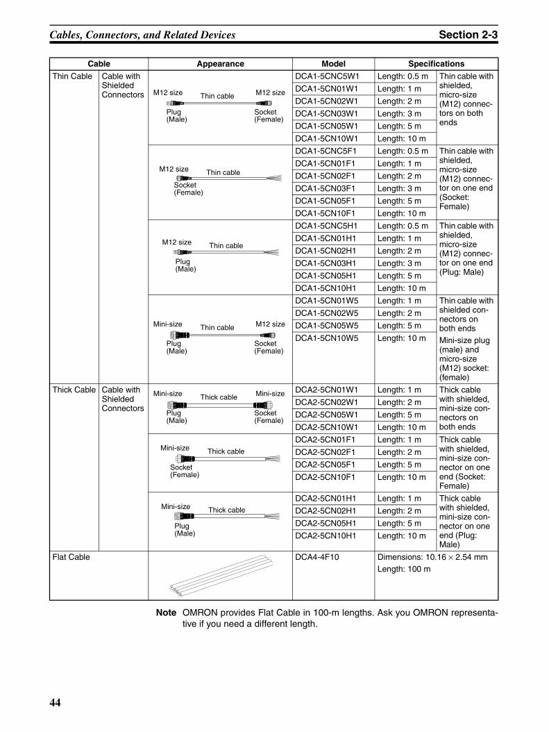
Cables, Connectors, and Related Devices Section 2-3
Note OMRON provides Flat Cable in 100-m lengths. Ask you OMRON representa-tive if you need a different length.
Thin Cable Cable with Shielded Connectors
DCA1-5CNC5W1 Length: 0.5 m Thin cable with shielded, micro-size (M12) connec-tors on both ends
DCA1-5CN01W1 Length: 1 m
DCA1-5CN02W1 Length: 2 m
DCA1-5CN03W1 Length: 3 m
DCA1-5CN05W1 Length: 5 m
DCA1-5CN10W1 Length: 10 m
DCA1-5CNC5F1 Length: 0.5 m Thin cable with shielded, micro-size (M12) connec-tor on one end (Socket: Female)
DCA1-5CN01F1 Length: 1 m
DCA1-5CN02F1 Length: 2 m
DCA1-5CN03F1 Length: 3 m
DCA1-5CN05F1 Length: 5 m
DCA1-5CN10F1 Length: 10 m
DCA1-5CNC5H1 Length: 0.5 m Thin cable with shielded, micro-size (M12) connec-tor on one end (Plug: Male)
DCA1-5CN01H1 Length: 1 m
DCA1-5CN02H1 Length: 2 m
DCA1-5CN03H1 Length: 3 m
DCA1-5CN05H1 Length: 5 m
DCA1-5CN10H1 Length: 10 m
DCA1-5CN01W5 Length: 1 m Thin cable with shielded con-nectors on both endsMini-size plug (male) and micro-size (M12) socket: (female)
DCA1-5CN02W5 Length: 2 m
DCA1-5CN05W5 Length: 5 m
DCA1-5CN10W5 Length: 10 m
Thick Cable Cable with Shielded Connectors
DCA2-5CN01W1 Length: 1 m Thick cable with shielded, mini-size con-nectors on both ends
DCA2-5CN02W1 Length: 2 m
DCA2-5CN05W1 Length: 5 m
DCA2-5CN10W1 Length: 10 m
DCA2-5CN01F1 Length: 1 m Thick cable with shielded, mini-size con-nector on one end (Socket: Female)
DCA2-5CN02F1 Length: 2 m
DCA2-5CN05F1 Length: 5 m
DCA2-5CN10F1 Length: 10 m
DCA2-5CN01H1 Length: 1 m Thick cable with shielded, mini-size con-nector on one end (Plug: Male)
DCA2-5CN02H1 Length: 2 m
DCA2-5CN05H1 Length: 5 m
DCA2-5CN10H1 Length: 10 m
Flat Cable DCA4-4F10 Dimensions: 10.16 × 2.54 mmLength: 100 m
Cable Appearance Model Specifications
M12 size M12 size
Plug (Male)
Socket (Female)
Thin cable
M12 size
Socket (Female)
Thin cable
M12 size
Plug (Male)
Thin cable
Mini-size M12 size
Plug (Male)
Socket (Female)
Thin cable
Mini-size Mini-size
Plug (Male)
Socket (Female)
Thick cable
Mini-size
Socket (Female)
Thick cable
Mini-size
Plug (Male)
Thick cable
44

Cables, Connectors, and Related Devices Section 2-3
Communications Cable and Communications Distance
Note Thin cable includes the cables with shielded connectors attached.
Cable Max. network length
Max. branch line length
Max. total branch line length
Thick cable At 500 kbps: 100 mAt 250 kbps: 250 mAt 125 kbps: 500 m
6 m At 500 kbps: 39 mAt 250 kbps: 78 mAt 125 kbps: 156 m
Thin cable(See note.)
100 m
Flat cable At 500 kbps: 75 mAt 250 kbps: 150 mAt 125 kbps: 265 m
6 m At 500 kbps: 35 mAt 250 kbps: 48 mAt 125 kbps: 135 m
Wire type Color Function Symbol
Signal wires Blue Communications signal, Low CAN L
White Communications signal, High CAN H
Power wires Red Communications power, positive V+
Black Communications power, negative V−Shield wire --- Shield S
ConductorNo.
Insulationcolor
Application Nominal cross-section
Conductor resistance
(Ω/km)
Allowablecurrent (A)
1 Red V+(communica-tions power sup-ply positive side)
0.75 mm2 (AWG19)
25.0 max. 5 max.
2 White CAN H (signal high)
0.5 mm2 (AWG21)
37.5 max. ---
11.2 mm to 12.1 mm outside diameter
Woven shield
Shield wire
Signal wires(Blue and white)
Power wires(Red and black)
Signal wires(Blue and white)
Power wires(Red and black)
Shield wire
Woven shield
6.9 mm outside diameter
Red: V+
Black: V−
White: CAN H
Blue: CAN L
45

Cables, Connectors, and Related Devices Section 2-3
Connecting Communications Cables
Note The ground may introduce noise into the network if a poor quality ground isused and the FG terminal is connected to the V- terminal. If a good ground of100 Ω or less is not available, do not connect the communication power sup-ply’s FG and V- terminals.
Communications Cable Specifications
Special Thin/Thick Cable
3 Blue CAN L(signal low)
0.5 mm2 (AWG21)
37.5 max. ---
4 Black V−(communica-tions power sup-ply negative side)
0.75mm2 (AWG19)
25.0 max. 5 max.
ConductorNo.
Insulationcolor
Application Nominal cross-section
Conductor resistance
(Ω/km)
Allowablecurrent (A)
Terminators are required at both ends of the network.
V+ (Red)CAN H (White)
ShieldCAN L (Blue)
V- (Black)
V+ (Red)CAN H (White)
ShieldCAN L (Blue)
V- (Black)
Terminating Resistor(121 Ω)
TerminatingResistor(121 Ω)
Terminators are required at both ends of the network.
Trunk line
Branch line
Node Node
T-branch Tap orT-branch Connector
Power Supply Tap
T-branch Tap or T-branch Connector
Connec-torCommunications
Power Supply (24 V DC)
Ground(100 Ω or less)
Ground the network at one point only.
Item Thick Cable Thin Cable
Signal wires Power wires Signal wires Power wires
Model DCA2-5C10 DCA1-5C10
Conductor cross-sectional area 0.86 mm2 2.17 mm2 0.20 mm2 0.38 mm2
Conductor outer diameter 1.21 mm 1.92 mm 0.60 mm 0.80 mm
Color Blue and white Red and black Blue and white Red and black
Impedance 120 Ω ±10% --- 120 Ω ±10% ---
Propagation delay 1.36 ns/ft --- 1.36 ns/ft ---
Attenuation factor 500 kHz: 0.25 dB/100 ft125 kHz: 0.13 dB/100 ft
--- 500 kHz: 0.50 dB/100 ft125 kHz: 0.29 dB/100 ft
---
Conductor resistance 6.9 Ω/1,000 ft22.6 Ω/1,000 m
2.7 Ω/1,000 ft8.9 Ω/1,000 m
28 Ω/1,000 ft91.9 Ω/1,000 m
17.5 Ω/1,000 ft57.4 Ω/1,000 m
Maximum current --- 8 A --- 3 A
Finished outer diameter 11.2 to 12.1 mm 6.9 mm
46
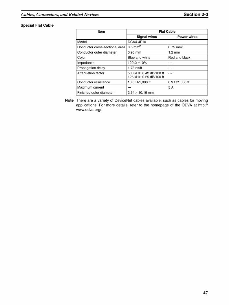
Cables, Connectors, and Related Devices Section 2-3
Special Flat Cable
Note There are a variety of DeviceNet cables available, such as cables for movingapplications. For more details, refer to the homepage of the ODVA at http://www.odva.org/.
Item Flat Cable
Signal wires Power wires
Model DCA4-4F10
Conductor cross-sectional area 0.5 mm2 0.75 mm2
Conductor outer diameter 0.95 mm 1.2 mm
Color Blue and white Red and black
Impedance 120 Ω ±10% ---
Propagation delay 1.78 ns/ft ---
Attenuation factor 500 kHz: 0.42 dB/100 ft125 kHz: 0.25 dB/100 ft
---
Conductor resistance 10.6 Ω/1,000 ft 6.9 Ω/1,000 ft
Maximum current --- 5 A
Finished outer diameter 2.54 × 10.16 mm
47

Cables, Connectors, and Related Devices Section 2-3
2-3-2 Connectors for Node Connections
Standard Connectors The following table shows the standard connectors provided with Masters,Slaves, and T-branch Taps.
Name Model Specifications Remarks
Straight Connector with Attachment Screws
XW4B-05C1-H1-D Straight connector with attachment screwsThe insertion and wiring directions are the same.
This connector is provided with the DCN1-1C/2C/3C/4C T-branch Taps as well as Masters and Slaves other than those listed in the note.
COMBICON Plug PHOENIX CONTACTMSTB 2.5/5-ST-5.08 AU
Straight connector with-out connector attachment screws.The insertion and wiring directions are the same.
This connector is provided with the Masters and Slaves listed in the note.
Right-angle Connector with Attach-ment Screws
XW4B-05C1-VIR-D Right-angle connector with attachment screwsThe insertion and wiring directions are perpendicu-lar.
This connector is provided with the DCN1-2R/4R T-branch Taps.
Straight Clamp Connector with Attachment Screws
XW4G-05C1-H1-D Straight connector with attachment screwsThe insertion and wiring directions are the same.
This connector is provided with the DCN1-1NC/3NC T-branch Taps and DRT2-series Masters and Slaves.
Flat Cable Connector DCN4-SF4D Flat cable pressure-weld connector with attachment screws
---
Attachment screws
Insertion direction
Wiring direction
Insertion direction
Wiring direction
Attachment screw Insertion
direction
Wiring direction
Insertion direction
Wiring direction
Attachment screw
Insertiondirection
Attachmentscrew
Wiringdirection
48
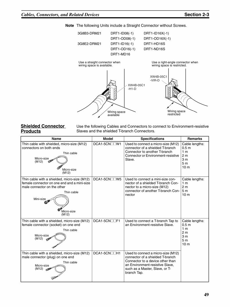
Cables, Connectors, and Related Devices Section 2-3
Note The following Units include a Straight Connector without Screws.
Shielded Connector Products
Use the following Cables and Connectors to connect to Environment-resistiveSlaves and the shielded T-branch Connectors.
3G8B3-DRM21 DRT1-ID08(-1) DRT1-ID16X(-1)
DRT1-OD08(-1) DRT1-OD16X(-1)
3G8E2-DRM21 DRT1-ID16(-1) DRT1-HD16S
DRT1-OD16(-1) DRT1-ND16S
DRT1-MD16
XW4B-05C1-H1-D
XW4B-05C1-VIR-D
Use a straight connector when wiring space is available.
Use a right-angle connector when wiring space is restricted.
Wiring space available
Wiring space restricted
Name Model Specifications Remarks
Thin cable with shielded, micro-size (M12) connectors on both ends
DCA1-5CN@@W1 Used to connect a micro-size (M12) connector of a shielded T-branch Connector to another T-branch Connector or Environment-resistive Slave.
Cable lengths:0.5 m1 m2 m3 m5 m10 m
Thin cable with a shielded, micro-size (M12) female connector on one end and a mini-size male connector on the other
DCA1-5CN@@W5 Used to connect a mini-size con-nector of a shielded T-branch Con-nector to a micro-size (M12) connector of another T-branch Con-nector
Cable lengths:1 m2 m5 m10 m
Thin cable with a shielded, micro-size (M12) female connector (socket) on one end
DCA1-5CN@@F1 Used to connect a T-branch Tap to an Environment-resistive Slave.
Cable lengths:0.5 m1 m2 m3 m5 m10 m
Thin cable with a shielded, micro-size (M12) male connector (plug) on one end
DCA1-5CN@@H1 Used to connect a micro-size (M12) connector of a shielded T-branch Connector to a device other than an Environment-resistive Slave, such as a Master, Slave, or T-branch Tap.
Micro-size (M12)
Thin cable
Micro-size (M12)
Micro-size (M12)
Thin cable
Mini-size
Thin cable
Micro-size (M12)
Thin cableMicro-size (M12)
49
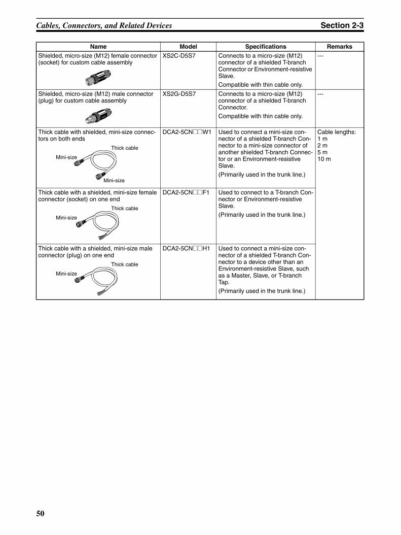
Cables, Connectors, and Related Devices Section 2-3
Shielded, micro-size (M12) female connector (socket) for custom cable assembly
XS2C-D5S7 Connects to a micro-size (M12) connector of a shielded T-branch Connector or Environment-resistive Slave.Compatible with thin cable only.
---
Shielded, micro-size (M12) male connector (plug) for custom cable assembly
XS2G-D5S7 Connects to a micro-size (M12) connector of a shielded T-branch Connector.Compatible with thin cable only.
---
Thick cable with shielded, mini-size connec-tors on both ends
DCA2-5CN@@W1 Used to connect a mini-size con-nector of a shielded T-branch Con-nector to a mini-size connector of another shielded T-branch Connec-tor or an Environment-resistive Slave.
(Primarily used in the trunk line.)
Cable lengths:1 m2 m5 m10 m
Thick cable with a shielded, mini-size female connector (socket) on one end
DCA2-5CN@@F1 Used to connect to a T-branch Con-nector or Environment-resistive Slave.
(Primarily used in the trunk line.)
Thick cable with a shielded, mini-size male connector (plug) on one end
DCA2-5CN@@H1 Used to connect a mini-size con-nector of a shielded T-branch Con-nector to a device other than an Environment-resistive Slave, such as a Master, Slave, or T-branch Tap.(Primarily used in the trunk line.)
Name Model Specifications Remarks
Thick cable
Mini-size
Mini-size
Thick cable
Mini-size
Thick cable
Mini-size
50
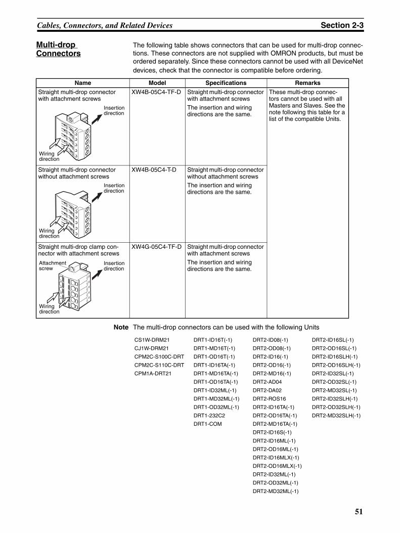
Cables, Connectors, and Related Devices Section 2-3
Multi-drop Connectors
The following table shows connectors that can be used for multi-drop connec-tions. These connectors are not supplied with OMRON products, but must beordered separately. Since these connectors cannot be used with all DeviceNetdevices, check that the connector is compatible before ordering.
Note The multi-drop connectors can be used with the following Units
Name Model Specifications Remarks
Straight multi-drop connector with attachment screws
XW4B-05C4-TF-D Straight multi-drop connector with attachment screws
The insertion and wiring directions are the same.
These multi-drop connec-tors cannot be used with all Masters and Slaves. See the note following this table for a list of the compatible Units.
Straight multi-drop connector without attachment screws
XW4B-05C4-T-D Straight multi-drop connector without attachment screwsThe insertion and wiring directions are the same.
Straight multi-drop clamp con-nector with attachment screws
XW4G-05C4-TF-D Straight multi-drop connector with attachment screws
The insertion and wiring directions are the same.
CS1W-DRM21 DRT1-ID16T(-1) DRT2-ID08(-1) DRT2-ID16SL(-1)
CJ1W-DRM21 DRT1-MD16T(-1) DRT2-OD08(-1) DRT2-OD16SL(-1)
CPM2C-S100C-DRT DRT1-OD16T(-1) DRT2-ID16(-1) DRT2-ID16SLH(-1)
CPM2C-S110C-DRT DRT1-ID16TA(-1) DRT2-OD16(-1) DRT2-OD16SLH(-1)
CPM1A-DRT21 DRT1-MD16TA(-1) DRT2-MD16(-1) DRT2-ID32SL(-1)
DRT1-OD16TA(-1) DRT2-AD04 DRT2-OD32SL(-1)
DRT1-ID32ML(-1) DRT2-DA02 DRT2-MD32SL(-1)
DRT1-MD32ML(-1) DRT2-ROS16 DRT2-ID32SLH(-1)
DRT1-OD32ML(-1) DRT2-ID16TA(-1) DRT2-OD32SLH(-1)
DRT1-232C2 DRT2-OD16TA(-1) DRT2-MD32SLH(-1)
DRT1-COM DRT2-MD16TA(-1)
DRT2-ID16S(-1)
DRT2-ID16ML(-1)
DRT2-OD16ML(-1)
DRT2-ID16MLX(-1)
DRT2-OD16MLX(-1)
DRT2-ID32ML(-1)
DRT2-OD32ML(-1)
DRT2-MD32ML(-1)
Insertion direction
Wiring direction
Insertion direction
Wiring direction
Insertion direction
Wiring direction
Attachment screw
51
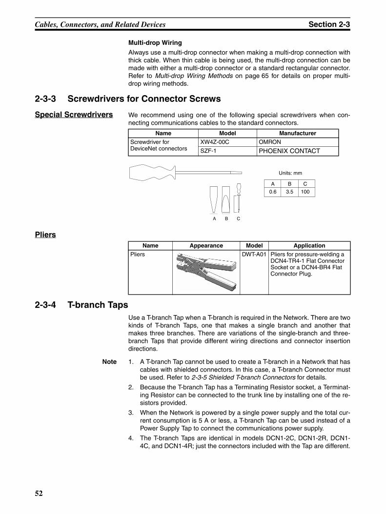
Cables, Connectors, and Related Devices Section 2-3
Multi-drop Wiring
Always use a multi-drop connector when making a multi-drop connection withthick cable. When thin cable is being used, the multi-drop connection can bemade with either a multi-drop connector or a standard rectangular connector.Refer to Multi-drop Wiring Methods on page 65 for details on proper multi-drop wiring methods.
2-3-3 Screwdrivers for Connector Screws
Special Screwdrivers We recommend using one of the following special screwdrivers when con-necting communications cables to the standard connectors.
Pliers
2-3-4 T-branch TapsUse a T-branch Tap when a T-branch is required in the Network. There are twokinds of T-branch Taps, one that makes a single branch and another thatmakes three branches. There are variations of the single-branch and three-branch Taps that provide different wiring directions and connector insertiondirections.
Note 1. A T-branch Tap cannot be used to create a T-branch in a Network that hascables with shielded connectors. In this case, a T-branch Connector mustbe used. Refer to 2-3-5 Shielded T-branch Connectors for details.
2. Because the T-branch Tap has a Terminating Resistor socket, a Terminat-ing Resistor can be connected to the trunk line by installing one of the re-sistors provided.
3. When the Network is powered by a single power supply and the total cur-rent consumption is 5 A or less, a T-branch Tap can be used instead of aPower Supply Tap to connect the communications power supply.
4. The T-branch Taps are identical in models DCN1-2C, DCN1-2R, DCN1-4C, and DCN1-4R; just the connectors included with the Tap are different.
Name Model Manufacturer
Screwdriver for DeviceNet connectors
XW4Z-00C OMRON
SZF-1 PHOENIX CONTACT
A B C
A
0.6
B
3.5
C
100
Units: mm
Name Appearance Model Application
Pliers
DWT-A01 Pliers for pressure-welding a DCN4-TR4-1 Flat Connector Socket or a DCN4-BR4 Flat Connector Plug.
52
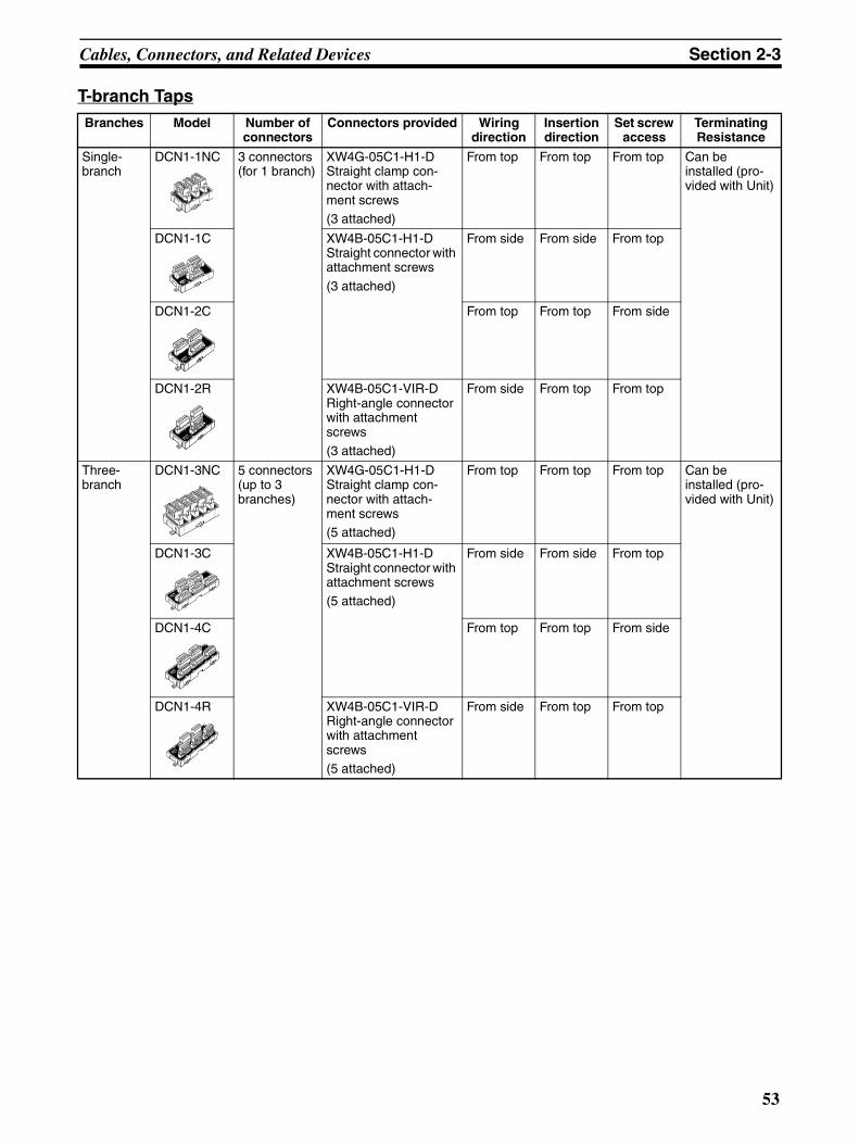
Cables, Connectors, and Related Devices Section 2-3
T-branch TapsBranches Model Number of
connectorsConnectors provided Wiring
directionInsertion direction
Set screw access
Terminating Resistance
Single-branch
DCN1-1NC 3 connectors (for 1 branch)
XW4G-05C1-H1-D Straight clamp con-nector with attach-ment screws(3 attached)
From top From top From top Can be installed (pro-vided with Unit)
DCN1-1C XW4B-05C1-H1-D Straight connector with attachment screws
(3 attached)
From side From side From top
DCN1-2C From top From top From side
DCN1-2R XW4B-05C1-VIR-D Right-angle connector with attachment screws
(3 attached)
From side From top From top
Three-branch
DCN1-3NC 5 connectors (up to 3 branches)
XW4G-05C1-H1-D Straight clamp con-nector with attach-ment screws(5 attached)
From top From top From top Can be installed (pro-vided with Unit)
DCN1-3C XW4B-05C1-H1-D Straight connector with attachment screws(5 attached)
From side From side From top
DCN1-4C From top From top From side
DCN1-4R XW4B-05C1-VIR-D Right-angle connector with attachment screws(5 attached)
From side From top From top
53
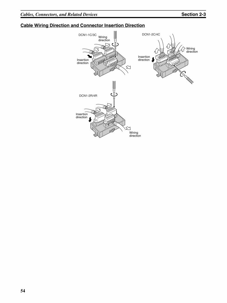
Cables, Connectors, and Related Devices Section 2-3
Cable Wiring Direction and Connector Insertion Direction
DCN1-1C/3C DCN1-2C/4C
DCN1-2R/4R
Wiring direction
Insertion direction
Wiring direction
Insertion direction
Insertion direction
Wiring direction
54

Cables, Connectors, and Related Devices Section 2-3
Components and their Functions
DCN1-1NC T-branch Tap Components
DCN1-1C T-branch Tap Components
Mounting screw holesUse when screwing the T-branch Tap to a control panel.
ON/OFF switch
DIN Track mounting hookUse when mounting the Tap to a DIN Track.A trunk line is usually connected here.
Communications ConnectorsConnect the network communications cable to the provided XW4G-05C1-H1-D Connectors.
DCN1-1CT-PORT TAP
Mounting screw holesUse when screwing the T-branch Tap to a control panel.
Terminating Resistor socketConnect a Terminating Resistor here if the T-branch Tap is installed at the end of the trunk line.
Communications ConnectorsConnect the network communications cable to the provided XW4B-05C1-H1-D Straight Connectors.
Communications ConnectorConnect the network communications cable to the provided XW4B-05C1-H1-D Straight Connector.
DIN Track mounting hookUse when mounting the Tap to a DIN Track.A trunk line is usually connected here.
55

Cables, Connectors, and Related Devices Section 2-3
DCN1-2C and DCN1-2R T-branch Tap Components
DCN1-3NC T-branch Tap Components
DCN1-2T-PORT TAP
Mounting screw holesUse when screwing the T-branch Tap to a control panel.
Terminating Resistor socketConnect a Terminating Resistor here if the T-branch Tap is installed at the end of the trunk line.
Communications ConnectorsConnect the network communications cable. The following connectors are provided.DCN1-2C: XW4B-05C1-H1-D Straight Connector with attachment screwsDCN1-2R: XW4B-05C1-VIR-D Right-angle Connector with attachment screws
Communications ConnectorConnect the network communications cable. The following connectors are provided.DCN1-2C: XW4B-05C1-H1-D Straight Connector with attachment screwsDCN1-2R: XW4B-05C1-VIR-D Right-angle Connector with attachment screws
DIN Track mounting hookUse when mounting the Tap to a DIN Track.A trunk line is usually connected here.
Mounting screw holesUse when screwing the T-branch Tap to a control panel.
DIN Track mounting hooksUse when mounting the Tap to a DIN Track.A trunk line is usually connected here.
Communications ConnectorsConnect the network communications cable. The following connectors are provided.XW4G-05C1-H1-D Straight Clamp Connector with attachment screws
ON/OFF switch
56
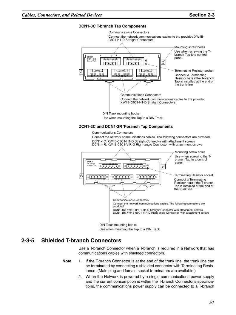
Cables, Connectors, and Related Devices Section 2-3
DCN1-3C T-branch Tap Components
DCN1-2C and DCN1-2R T-branch Tap Components
2-3-5 Shielded T-branch ConnectorsUse a T-branch Connector when a T-branch is required in a Network that hascommunications cables with shielded connectors.
Note 1. If the T-branch Connector is at the end of the trunk line, the trunk line canbe terminated by connecting a shielded connector with Terminating Resis-tance. (Male plug and female socket terminators are available.)
2. When the Network is powered by a single communications power supplyand the current consumption is within the T-branch Connector’s specifica-tions, the communications power supply can be connected to a T-branch
DCN1-3CT-PORT TAP
Mounting screw holesUse when screwing the T-branch Tap to a control panel.
Terminating Resistor socketConnect a Terminating Resistor here if the T-branch Tap is installed at the end of the trunk line.
Communications ConnectorsConnect the network communications cables to the provided XW4B-05C1-H1-D Straight Connectors.
Communications ConnectorsConnect the network communications cables to the provided XW4B-05C1-H1-D Straight Connectors.
DIN Track mounting hooksUse when mounting the Tap to a DIN Track.
DCN1-4T-PORT TAP
Mounting screw holesUse when screwing the T-branch Tap to a control panel.
Terminating Resistor socketConnect a Terminating Resistor here if the T-branch Tap is installed at the end of the trunk line.
Communications ConnectorsConnect the network communications cables. The following connectors are provided.DCN1-4C: XW4B-05C1-H1-D Straight Connector with attachment screwsDCN1-4R: XW4B-05C1-VIR-D Right-angle Connector with attachment screws
Communications ConnectorsConnect the network communications cables. The following connectors are provided.DCN1-4C: XW4B-05C1-H1-D Straight Connector with attachment screwsDCN1-4R: XW4B-05C1-VIR-D Right-angle Connector with attachment screws
DIN Track mounting hooksUse when mounting the Tap to a DIN Track.
57
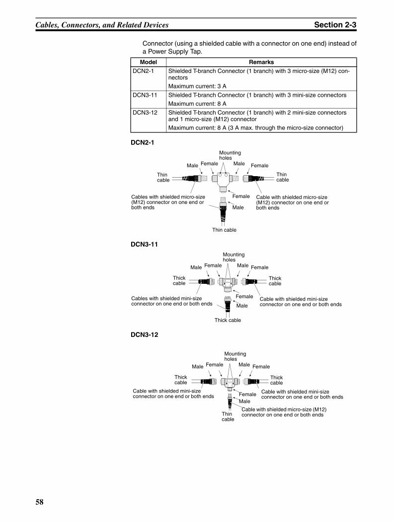
Cables, Connectors, and Related Devices Section 2-3
Connector (using a shielded cable with a connector on one end) instead ofa Power Supply Tap.
DCN2-1
DCN3-11
DCN3-12
Model Remarks
DCN2-1 Shielded T-branch Connector (1 branch) with 3 micro-size (M12) con-nectors
Maximum current: 3 A
DCN3-11 Shielded T-branch Connector (1 branch) with 3 mini-size connectors
Maximum current: 8 A
DCN3-12 Shielded T-branch Connector (1 branch) with 2 mini-size connectors and 1 micro-size (M12) connector
Maximum current: 8 A (3 A max. through the micro-size connector)
Thin cable
Thin cable
Thin cable
Cable with shielded micro-size (M12) connector on one end or both ends
Cables with shielded micro-size (M12) connector on one end or both ends
Male Female Male Female
Female
Male
Mounting holes
Thick cable
Thick cable
Thick cable
Cable with shielded mini-size connector on one end or both ends
Cables with shielded mini-size connector on one end or both ends
Male Female Male Female
Female
Male
Mounting holes
Thick cable
Thick cable
Thin cable
Cable with shielded mini-size connector on one end or both ends
Cable with shielded mini-size connector on one end or both ends
Male Female Male Female
FemaleMale
Mounting holes
Cable with shielded micro-size (M12) connector on one end or both ends
58
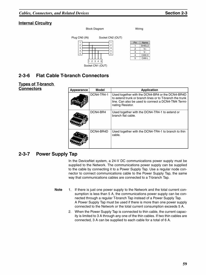
Cables, Connectors, and Related Devices Section 2-3
Internal Circuitry
2-3-6 Flat Cable T-branch Connectors
Types of T-branch Connectors
2-3-7 Power Supply TapIn the DeviceNet system, a 24-V DC communications power supply must besupplied to the Network. The communications power supply can be suppliedto the cable by connecting it to a Power Supply Tap. Use a regular node con-nector to connect communications cable to the Power Supply Tap, the sameway that communications cables are connected to a T-branch Tap.
Note 1. If there is just one power supply to the Network and the total current con-sumption is less than 5 A, the communications power supply can be con-nected through a regular T-branch Tap instead of a Power Supply Tap.A Power Supply Tap must be used if there is more than one power supplyconnected to the Network or the total current consumption exceeds 5 A.
2. When the Power Supply Tap is connected to thin cable, the current capac-ity is limited to 3 A through any one of the thin cables. If two thin cables areconnected, 3 A can be supplied to each cable for a total of 6 A.
12345
12345
1 2 3 4 5
Pin12345
NameSHIELD
V+V−
CAN HCAN L
Block Diagram
Plug CN0 (IN) Socket CN2 (OUT)
Socket CN1 (OUT)
Wiring
Appearance Model Application
DCN4-TR4-1 Used together with the DCN4-BR4 or the DCN4-BR4D to extend trunk or branch lines or to T-branch the trunk line. Can also be used to connect a DCN4-TM4 Termi-nating Resistor.
DCN4-BR4 Used together with the DCN4-TR4-1 to extend or branch flat cable.
DCN4-BR4D Used together with the DCN4-TR4-1 to branch to thin cable.
59

Cables, Connectors, and Related Devices Section 2-3
(If two thick cables are connected, 8 A can be supplied to each cable for atotal of 16 A.)
Internal Circuitry
2-3-8 Terminating ResistorsIn a DeviceNet Network, one Terminating Resistor must be connected to eachend of the trunk line. If a Unit is at the end of the trunk line, connect one of theTerminating Resistors listed in the following table because the Units do nothave built-in terminators.
There are several ways to connect a Terminating Resistor. A special Terminal-block Terminating Resistor can be connected, a resistor can be installed in theTerminating Resistor socket of a T-branch Tap or Power Supply Tap, or ashielded connector with terminating resistance can be connected to a T-branch Connector. A Terminating Resistor is provided with T-branch Taps andPower Supply Taps. If a resistor is to be installed on a T-branch Tap or PowerSupply Tap, always use the provided Terminating Resistor.
Model Remarks
DCN1-1P Includes two XW4B-05C1-H1-D Straight Connectors with attachment screws, a terminator (attach if needed), fuses, and a ground terminal.
Communications Connectors
Communications Power Supply (24 V DC)
PinV−LSHV+
NameV−
CAN LSHIELDCAN H
V+CN2
CN3
F2
F1
CN1
V−'L'S'
SV
−V
+
H'V+'
V+HSL
CN4
V−
Model Remarks
(No model number) Terminating Resistor provided with T-branch Taps and Power Supply Taps (121 Ω ±1%, 1/4 W)
DRS1-T Terminal-block Terminating Resistor (121 Ω ±1%, 1/4 W)
DRS2-1 Shielded Micro-size (M12) Connector with Terminating Resis-tance (male plug)
DRS2-2 Shielded Micro-size (M12) Connector with Terminating Resis-tance (female socket)
60

Cables, Connectors, and Related Devices Section 2-3
2-3-9 Communications Power SupplyIn a DeviceNet system, a 24-V DC communications power supply must besupplied to the Network. The communications power supply must meet thespecifications listed in the following table and the AC inputs and DC outputsmust be isolated.
The OMRON S82J-series and S82K-series Power Supply Units are recom-mended. Select a Power Supply Unit with a current capacity that can comfort-ably handle the total power consumption of all connected nodes and allow forfuture expansion if necessary.
Communications Power Supply Specifications
The communications power supply must meet the following specifications.
DRS3-1 Shielded Mini-size Connector with Terminating Resistance (male plug)
DCN4-TM4 Used to connect the DCN4-TR4-1.
DCN4-TP4D Flat Cable Power Supply Terminal Block with Terminating Resistance
When flat cable is used, communications power can be sup-plied from the terminals on this terminal block.
Model Remarks
Item Specifications
Output voltage 24 V DC ±1%
Output current 16 A max.
Input fluctuation 0.3% max.
Load fluctuation 0.3% max.
Temperature effect 0.03%/°C max.
Input voltage 100 to 1,200 V
Input frequency 47 to 450 Hz
Output ripple 250 mVp-p
Output capacitance 7,000 µF max.
Ambient temperature Operating: 0 to 60°CStorage: −40 to 85°C
Max. instantaneous output current
65 A max. (peak)
Overvoltage protection Must be provided.
Overcurrent protection Must be provided. (max. current: 125%)
Startup time Must reach 5% of final output voltage within 250 ms.
Startup overshoot 0.2% max.
Insulation Between output and AC power and between output and chassis ground
Standards Required: UL
Recommended: FCC Class B, CSA, TÜV, and VDE
61

Wiring Methods Section 2-4
Note The current capacity of thick cable is 8 A, so up to 16 A can be supplied to thenetwork by supplying communications power in two directions from the powersupply through thick cables.The current capacity of thin cable is limited to 3 A. Up to 6 A can be suppliedto the network when communications power is supplied in two directions fromthe power supply through thin cables.If a thin cable is connected in one direction and a thick cable is connected inthe other, the maximum current is 3 A + 8 A = 11 A total.
2-4 Wiring Methods
2-4-1 Wiring and Installing Standard Connectors
Attaching Communications Cables
Use the following procedure to prepare and connect the communicationscables to the connectors.
1,2,3... 1. Strip about 30 mm of the cable sheathing, being careful not to damage thewoven shield just below the sheathing. Do not remove more than about30 mm; removing too much of the covering can result in short circuits orallow noise into the Network.
2. Carefully peel back the woven shield. There is a bare shield wire under thewoven shield as well as the signal lines and power lines. (The shield wirewill be loose on the outside of the other lines, but it is stiffer than the wovenshield and easy to identify by touch.)
3. Cut away the exposed woven shield, remove the aluminum tape from thesignal and power lines, and strip the sheath from the signal and power linesto the proper length for the crimp terminal connectors. Twist together thestranded wires of each signal and power lines.
Ambient humidity 30% to 90% (with no condensation)
Surge current capacity 10% max.
Item Specifications
Approx. 30 mm
Shield wire
Strip proper length for the terminals being used.
62
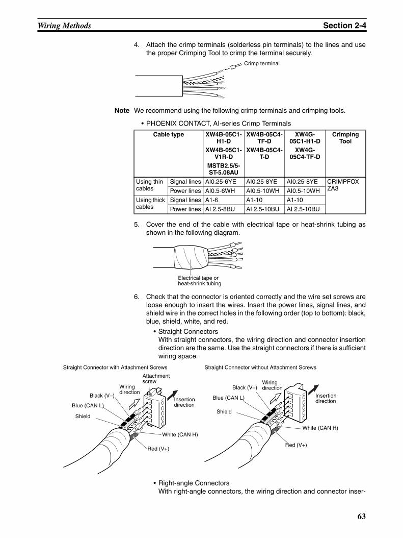
Wiring Methods Section 2-4
4. Attach the crimp terminals (solderless pin terminals) to the lines and usethe proper Crimping Tool to crimp the terminal securely.
Note We recommend using the following crimp terminals and crimping tools.
• PHOENIX CONTACT, AI-series Crimp Terminals
5. Cover the end of the cable with electrical tape or heat-shrink tubing asshown in the following diagram.
6. Check that the connector is oriented correctly and the wire set screws areloose enough to insert the wires. Insert the power lines, signal lines, andshield wire in the correct holes in the following order (top to bottom): black,blue, shield, white, and red.
• Straight ConnectorsWith straight connectors, the wiring direction and connector insertiondirection are the same. Use the straight connectors if there is sufficientwiring space.
• Right-angle ConnectorsWith right-angle connectors, the wiring direction and connector inser-
Crimp terminal
Cable type XW4B-05C1-H1-D
XW4B-05C1-V1R-D
MSTB2.5/5-ST-5.08AU
XW4B-05C4-TF-D
XW4B-05C4-T-D
XW4G-05C1-H1-D
XW4G-05C4-TF-D
Crimping Tool
Using thin cables
Signal lines AI0.25-6YE AI0.25-8YE AI0.25-8YE CRIMPFOX ZA3Power lines AI0.5-6WH AI0.5-10WH AI0.5-10WH
Using thick cables
Signal lines A1-6 A1-10 A1-10
Power lines AI 2.5-8BU AI 2.5-10BU AI 2.5-10BU
Electrical tape or heat-shrink tubing
Straight Connector with Attachment Screws
Black (V−)
Blue (CAN L)
Shield
White (CAN H)
Red (V+)
Black (V−)
Blue (CAN L)
Shield
White (CAN H)
Red (V+)
Straight Connector without Attachment Screws
Wiring direction
Wiring direction
Insertion direction
Insertion direction
Attachment screw
63

Wiring Methods Section 2-4
tion direction are perpendicular. Use right-angle connectors if there isinsufficient wiring space in front of the DeviceNet connectors and theconnectors must be wired from the side.
Connectors without set screws do not require lines to be secured withscrews as with previous connectors. Push up the orange lever andthen insert each line into the back of each hole. Release the orange lever after inserting the lines, and gently pull eachline to check that it is securely connected to the connector.
Note (a) Be sure that the wire set screws are sufficiently loosened beforeattempting to insert the lines. If these screws are not loose, thewires will go into the space in the back of the connector and can-not be locked with the set screws.
(b) There are colored stickers provided on the Master Unit and SlaveUnits that match the colors of the lines to be inserted. Be sure thatthe colors match when wiring the connectors.
(c) The following table shows the cable colors:
7. Tighten the connector’s set screws on the wires using a slotted screwdriverthat doesn’t taper at the tip, which will prevent the screwdriver from bindingin the connector. Tighten the screws to a torque of between 0.25 and0.3 N⋅m
Color Signal Symbol
Black Communications power supply, negative V−Blue Signal line, Low CAN L
--- Shield S
White Signal line, High CAN H
Red Communications power supply, positive V+
Insertion direction
White (CAN H)
Red (V+)
Black (V−)
Blue (CAN L)
Shield
Wiring direction
Attachment screw
Black (V−)
Red (V+)
Blue (CAN L)
White (CAN H)
Shield
64
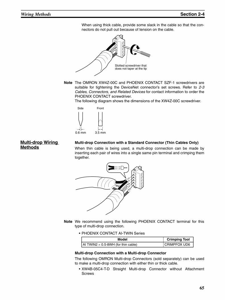
Wiring Methods Section 2-4
When using thick cable, provide some slack in the cable so that the con-nectors do not pull out because of tension on the cable.
Note The OMRON XW4Z-00C and PHOENIX CONTACT SZF-1 screwdrivers aresuitable for tightening the DeviceNet connector’s set screws. Refer to 2-3Cables, Connectors, and Related Devices for contact information to order thePHOENIX CONTACT screwdriver.The following diagram shows the dimensions of the XW4Z-00C screwdriver.
Multi-drop Wiring Methods
Multi-drop Connection with a Standard Connector (Thin Cables Only)
When thin cable is being used, a multi-drop connection can be made byinserting each pair of wires into a single same pin terminal and crimping themtogether.
Note We recommend using the following PHOENIX CONTACT terminal for thistype of multi-drop connection.
• PHOENIX CONTACT AI-TWIN Series
Multi-drop Connection with a Multi-drop Connector
The following OMRON Multi-drop Connectors (sold separately) can be usedto make a multi-drop connection with either thin or thick cable.
• XW4B-05C4-T-D Straight Multi-drop Connector without AttachmentScrews
Slotted screwdriver that does not taper at the tip
3.5 mm0.6 mm
Side Front
Model Crimping Tool
AI TWIN2 × 0.5-8WH (for thin cable) CRIMPFOX UD6
65

Wiring Methods Section 2-4
• XW4B-05C4-TF-D Straight Multi-drop Connector with Attachment Screws
• XW4G-05C4-TF-D Straight Multi-drop Clamp Connector with AttachmentScrews
In some cases, the Multi-drop Connector cannot be used because there is notenough space and other Units or connectors get in the way. Refer to Multi-drop Connectors on page 51 for a list of compatible Units.
Note 1. Before connecting the communications cables, turn OFF the power sup-plies to the PLC and all Slaves, as well as the communications power sup-plies.
2. Use crimp terminals for wiring. Connecting bare twisted wires can causethe cables to come OFF, break, or short circuit and result in incorrect op-eration and possibly damage to the Units.
3. Use the proper crimping tool and crimping methods when attaching crimpterminals. Consult the manufacturer of the tools and terminals you are us-ing. Inappropriate tools or methods can result in broken wires.
4. Be extremely careful to wire all signal lines, power lines, and shielding wirecorrectly.
5. Tighten all set screws firmly. Tighten signal lines, power lines, and shield-ing wire to a torque of 0.5 to 0.6 N⋅m. Tighten connector screws to a torqueof 0.4 to 0.5 N⋅m.
6. Wire the signal lines, power lines, and shielding wire so that they do notbecome disconnected during communications.
7. Do not pull on the communications cables. They may become disconnect-ed or wires may break.
8. Allow a sufficient bending radius in cable turns so that communications ca-bles are not bent too sharply. The Cables may become disconnected orwires may break if the cables are bent too far.
9. Never place objects on top of the communications cables. They may break.
10. Double-check all wiring before turning ON the power supply.
2-4-2 Attaching Flat Cable ConnectorsFlat Connector Plug Component Names
Cable identification label(Flat cable: Black, blue, white, red)
Black
66

Wiring Methods Section 2-4
1,2,3... 1. Cut the cable.Cut the cable perpendicular to the length. To prevent short-circuits, cut the cable with a sharp tool, such as wire cut-ters, and make sure that no whiskers are left on the wires.
2. Attach the cable.Align the indications on the cable identification label with the cable colorsand insert the cable. The cover is translucent, so it is possible to confirmthat the cable has been inserted all the way in.
3. Pressure-weld the connector.Use the DWT-A01 Pliers to pressure-weld the connectors.
1) As shown in the following diagram, align the center of the connector cov-er (see arrows) with the center of the pressure-welding block on the Pli-ers.
2) Squeeze firmly on the Pliers until the lock on the connector clicks intoplace.
Note 1. Do not pressure-weld the connector cover at the edges.
2. Do not pressure-weld the connector cover at the back of the pressure-welding block.
3. Set the connector in the correct orientation.
Confirm that the cable has been inserted up to this position.
Pliers Connector cover
OK NG
NG NG
67

Wiring Methods Section 2-4
3. After attaching the cable, confirm that it is properly pressure-welded asshown below.
2-4-3 Attaching Shielded ConnectorsUse the following procedure to attach shielded connectors to the communica-tions cables. This section explains the basic attachment procedure. For moredetails on connector assembly methods, refer to XS2 in the Sensor I/O Con-nectors Catalog (G05) (The connectors used for DeviceNet communicationscables use screws to secure the wires.)
1,2,3... 1. Insert the cable into the cap, cable clamp, water-tight bushing, and cover.
2. Prepare the communications cable, referring to the procedure describedunder Attaching Communications Cables in 2-4-1 Wiring and InstallingStandard Connectors.
3. When using shielded connectors, remove approximately 20 mm of the ca-ble covering, and strip approximately 8 mm of the sheath from the signallines and power lines (refer to the following diagram). Do not remove toomuch of the covering. Removing excessive cable covering may result in ashort circuit or the expected water-tight capabilities will not be provided.
4. Insert the signal lines, power lines and shield wire into the contact blockholes, making sure the terminal numbers are correct.
5. Tighten the contact block’s line set screws on each of the lines. Tighten theset screws to a torque of between 0.15 and 0.2 N⋅m using a special screw-driver.
Note Use the OMRON XW4Z-00B Screwdriver to tighten the line set screws of theshielded connector for custom cable assembly.
There should be no gaps here.
68
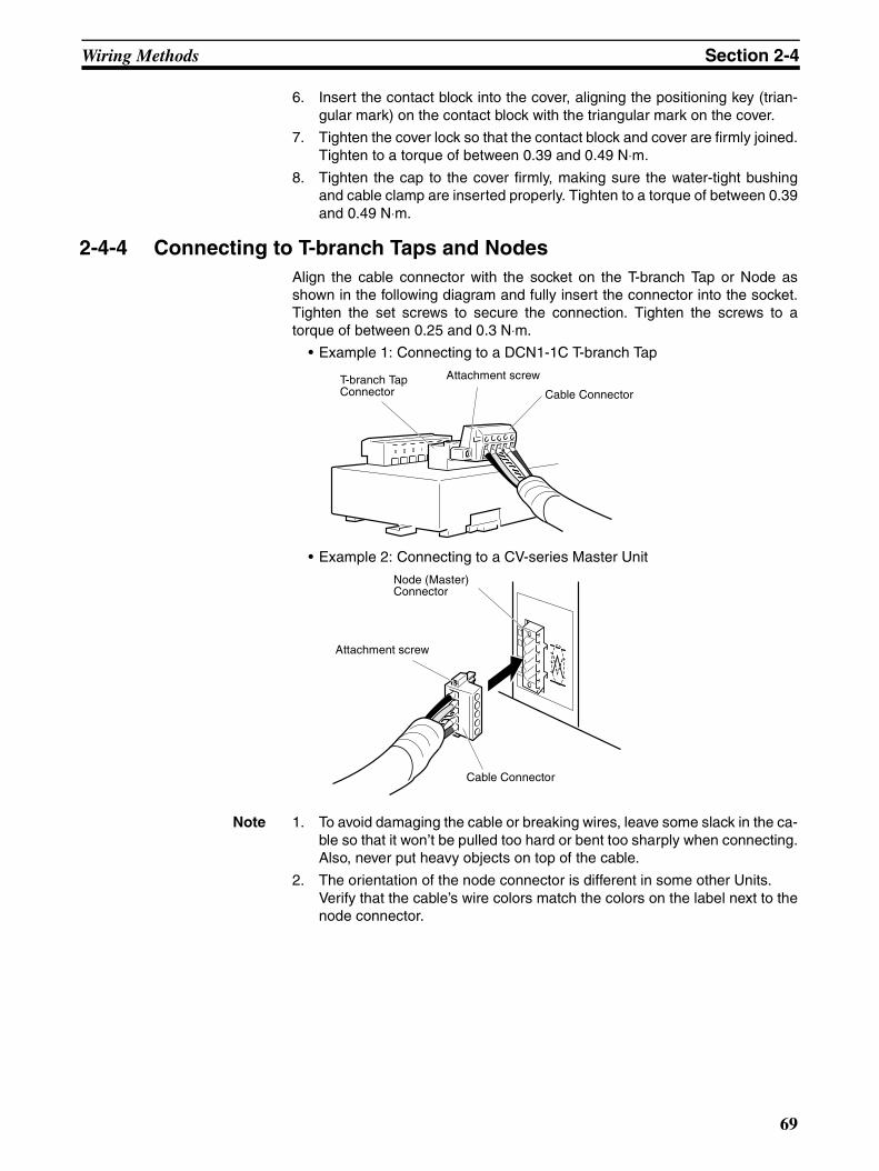
Wiring Methods Section 2-4
6. Insert the contact block into the cover, aligning the positioning key (trian-gular mark) on the contact block with the triangular mark on the cover.
7. Tighten the cover lock so that the contact block and cover are firmly joined.Tighten to a torque of between 0.39 and 0.49 N⋅m.
8. Tighten the cap to the cover firmly, making sure the water-tight bushingand cable clamp are inserted properly. Tighten to a torque of between 0.39and 0.49 N⋅m.
2-4-4 Connecting to T-branch Taps and NodesAlign the cable connector with the socket on the T-branch Tap or Node asshown in the following diagram and fully insert the connector into the socket.Tighten the set screws to secure the connection. Tighten the screws to atorque of between 0.25 and 0.3 N⋅m.
• Example 1: Connecting to a DCN1-1C T-branch Tap
• Example 2: Connecting to a CV-series Master Unit
Note 1. To avoid damaging the cable or breaking wires, leave some slack in the ca-ble so that it won’t be pulled too hard or bent too sharply when connecting.Also, never put heavy objects on top of the cable.
2. The orientation of the node connector is different in some other Units.Verify that the cable’s wire colors match the colors on the label next to thenode connector.
T-branch Tap Connector
Attachment screw
Cable Connector
Node (Master) Connector
Attachment screw
Cable Connector
69

Wiring Methods Section 2-4
2-4-5 Flat Cable I (Standard)
Preparing DCN4-TR4-1 Flat Connector Sockets
Component Names
Cutting the Cable (when Extending Cable or Connecting Terminating Resistance)
Cut the cable perpendicular to the length.
To prevent short-circuits, cut the cable with a sharp blade, such as wire cut-ters, and be sure that there are no whiskers on the wires.
Setting the Cable Stopper (when Extending Cable or Connecting Terminating Resistance)
A stopper must be set in advance when extending a line or connecting termi-nating resistance.
Close the cover, secure the hooks, and then press down on the cable stopperuntil it clicks into place.
Cover Housing
Cable confirmation slot
Cable labels(Flat cable: black, blue, white, and red)
Black
Cable stopperPress until you hear the stopper clicks and remains in place.
70
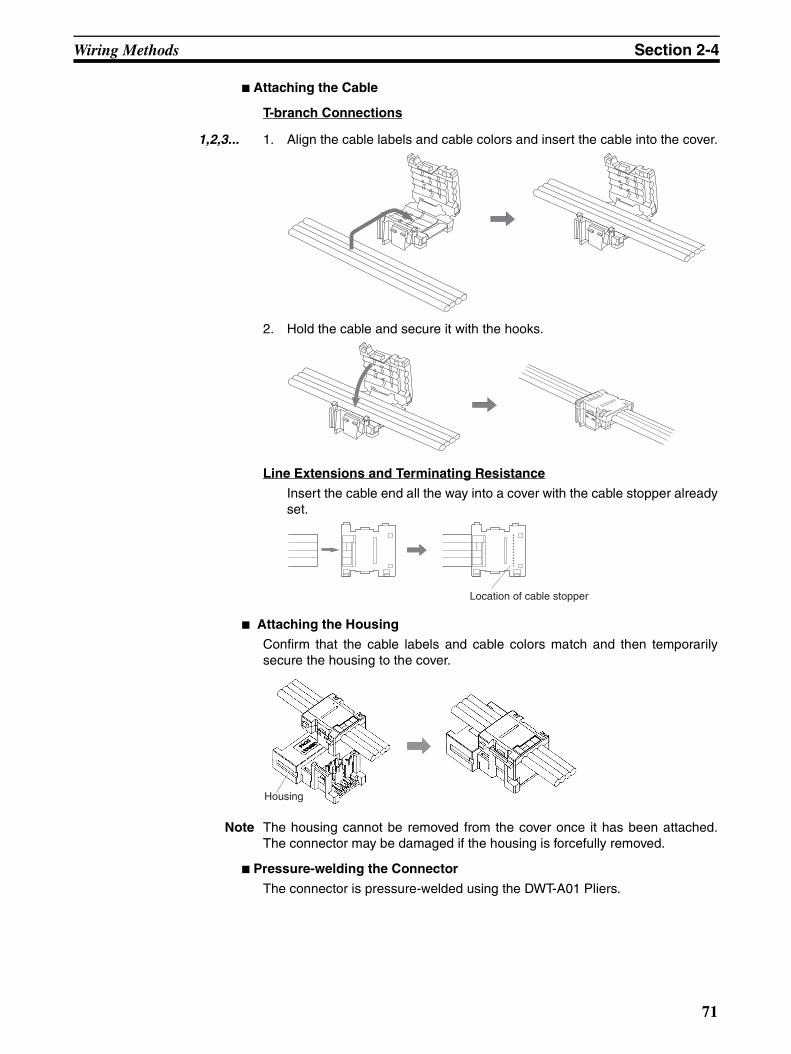
Wiring Methods Section 2-4
Attaching the Cable
T-branch Connections
1,2,3... 1. Align the cable labels and cable colors and insert the cable into the cover.
2. Hold the cable and secure it with the hooks.
Line Extensions and Terminating Resistance
Insert the cable end all the way into a cover with the cable stopper alreadyset.
Attaching the Housing
Confirm that the cable labels and cable colors match and then temporarilysecure the housing to the cover.
Note The housing cannot be removed from the cover once it has been attached.The connector may be damaged if the housing is forcefully removed.
Pressure-welding the Connector
The connector is pressure-welded using the DWT-A01 Pliers.
Location of cable stopper
Housing
71

Wiring Methods Section 2-4
1,2,3... 1. As shown below, align the center (see arrows) of the connector cover withthe center of the pressure-welding block on the Pliers.
2. Squeeze firmly on the Pliers until the lock on the connector clicks intoplace.
Note (1) Do not pressure-weld the connector cover at the edges.
(2) Do not pressure-weld the connector cover at the back of the pressure-welding block.
(3) Set the connector in the correct orientation.
3. After attaching the cable, confirm that it is properly pressure-welded asshown below.
Preparing DCN4-BR4 Flat Connector Plugs
Component Names
Cutting the Cable
Cut the cable perpendicular to the length.
Pliers Connector cover
OK NG
NG
Be sure the connector is locked on both the left and right sides.
Be sure there are no gaps here.
Cable labels(Flat cable: black, blue, white, and red)
Lock lever
Black
72

Wiring Methods Section 2-4
To prevent short-circuits, cut the cable with a sharp blade, such as wire cut-ters, and be sure that there are no whiskers on the wires.
Attaching the Cable
Align the cable labels and cable colors and insert the cable.
Confirm that the cable is inserted all the way to the back. (The cover is semi-transparent.)
Insert the cable to this point.
The connector is pressure-welded by using the DWT-A01 Pliers.
1,2,3... 1. As shown below, align the center (see arrows) of the connector cover withthe center of the pressure-welding block on the DWT-A01 Pliers.
2. Squeeze firmly on the Pliers until the lock on the connector clicks intoplace.
Note (1) Do not pressure-weld the connector cover at the edges.
(2) Do not pressure-weld the connector cover at the back of the pressure-welding block.
(3) Set the connector in the correct orientation.
Insert the cable to this point.
PliersConnector cover
OK
NG
NG
NG
73
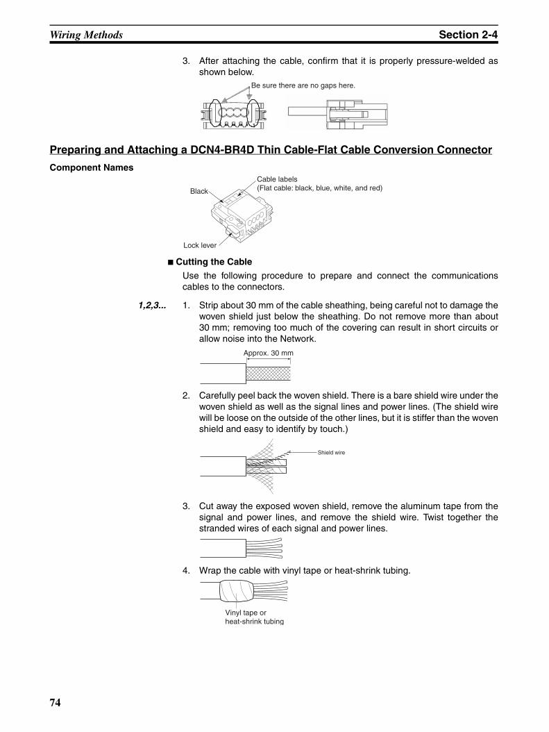
Wiring Methods Section 2-4
3. After attaching the cable, confirm that it is properly pressure-welded asshown below.
Preparing and Attaching a DCN4-BR4D Thin Cable-Flat Cable Conversion Connector
Component Names
Cutting the Cable
Use the following procedure to prepare and connect the communicationscables to the connectors.
1,2,3... 1. Strip about 30 mm of the cable sheathing, being careful not to damage thewoven shield just below the sheathing. Do not remove more than about30 mm; removing too much of the covering can result in short circuits orallow noise into the Network.
2. Carefully peel back the woven shield. There is a bare shield wire under thewoven shield as well as the signal lines and power lines. (The shield wirewill be loose on the outside of the other lines, but it is stiffer than the wovenshield and easy to identify by touch.)
3. Cut away the exposed woven shield, remove the aluminum tape from thesignal and power lines, and remove the shield wire. Twist together thestranded wires of each signal and power lines.
4. Wrap the cable with vinyl tape or heat-shrink tubing.
Be sure there are no gaps here.
Cable labels(Flat cable: black, blue, white, and red)
Lock lever
Black
Approx. 30 mm
Shield wire
Vinyl tape or heat-shrink tubing
74

Wiring Methods Section 2-4
Attaching the Cable
Align the indications on the cable identification label with the cable colors andinsert the cable. The cover is translucent, so it is possible to confirm that thecable has been inserted all the way in.
Pressure-welding the Connector
Use the DWT-A01 Pliers to pressure-weld the connector.
1,2,3... 1. As shown in the following diagram, align the center of the connector cover(see arrows) with the center of the pressure-welding block on the Pliers.
2. Squeeze firmly on the Pliers until the lock on the connector clicks intoplace.
Note (1) Do not pressure-weld the connector cover at the edges.
(2) Do not pressure-weld the connector cover at the back of the pressure-welding block.
(3) Set the connector in the correct orientation.
3. After attaching the cable, confirm that it is properly pressure-welded asshown below.
Confirm that the cable has been inserted up to this position.
Connector cover
Pliers
NG
NGNG
OK
Be sure there are no gaps here.
75

Wiring Methods Section 2-4
2-4-6 Connecting Shielded (Environment-resistive) CablesCheck that the connector (plug or socket) on the Shielded T-branch Connectoror Environment-resistive Slave is the opposite of the connector (socket orplug) on the Cable, align the connectors, and insert the cable connector.
Insert the connector fully and tighten the connector by hand. Tighten Micro-size Connectors to a torque of between 0.39 and 0.49 N⋅m. Tighten Mini-sizeConnectors to a torque of between 0.7 and 0.8 N⋅m.
Note (1) Tighten the connector ring securely by hand. If the connector is not tight-ened sufficiently, it will not provide the specified level of environmental re-sistance and might become loose due to vibration.Do not use a tool such as pliers to tighten the connector, because the toolcan damage the connector.
(2) To avoid damaging the cable or breaking wires, leave some slack in thecable so that it won’t be pulled too hard or bent too sharply when connect-ing. Also, never put heavy objects on top of the cable.
(3) The location of the connector and the type of connector (plug or socket)varies from device to device. Check the location and type of connector re-quired before wiring the devices.
2-4-7 Wiring the Communications Power SupplyThere are three ways to wire the communications power supply. The followingtable shows applications where each method can be used.
Note (1) The maximum current is 5 A for a T-branch Tap and 8 A for a T-branchConnector (3 A through a micro-size connector). Determine the currentconsumption for all nodes in both directions.
(2) A DCN2-1 T-branch Connector (for thin cable only) cannot be used be-cause the maximum current is 3 A. Also, when using a DC3-12 T-branchConnector that can connect to thin cable and thick cable, do not exceed3 A through the thin cable.
Method Number of com-munications
power supplies in Network
Total current consumption (See note 1.)
Connection method
1 2 or more
Less than 3 A
3 A to 5 A
More than 5 A
Connecting to aT-branch Tap
Yes No Yes Yes No Attach V+ and V− wires to a connector.
Connecting to aT-branch Con-nector
Yes No Yes Yes (See note 2.)
Yes (See note 2.)
Use just the V+ and V− from a thin cable with shielded con-nector on one end.
Connecting to a Power Supply Tap
Yes Yes Yes Yes Yes Wire V+ and V− wires to terminal block.
76
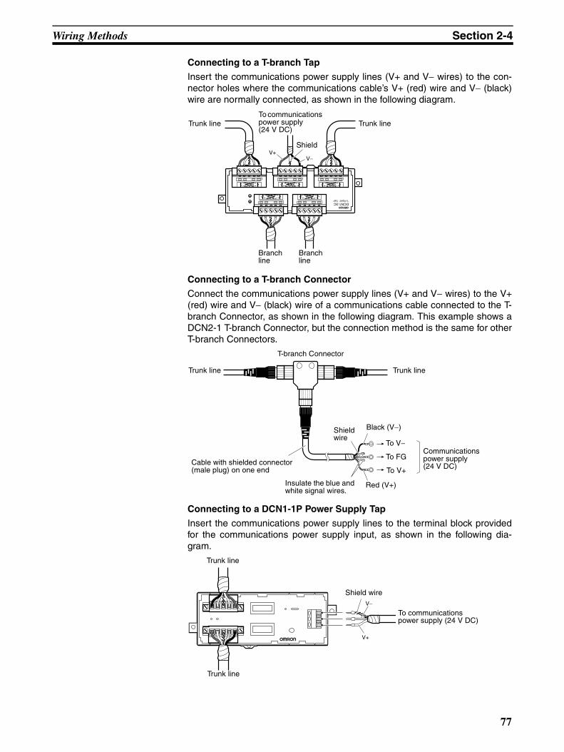
Wiring Methods Section 2-4
Connecting to a T-branch Tap
Insert the communications power supply lines (V+ and V− wires) to the con-nector holes where the communications cable’s V+ (red) wire and V− (black)wire are normally connected, as shown in the following diagram.
Connecting to a T-branch Connector
Connect the communications power supply lines (V+ and V− wires) to the V+(red) wire and V− (black) wire of a communications cable connected to the T-branch Connector, as shown in the following diagram. This example shows aDCN2-1 T-branch Connector, but the connection method is the same for otherT-branch Connectors.
Connecting to a DCN1-1P Power Supply Tap
Insert the communications power supply lines to the terminal block providedfor the communications power supply input, as shown in the following dia-gram.
DCN1-3CT-PORT TAP
V+V−
Trunk line Trunk line
Branch line
Branch line
Shield
To communications power supply (24 V DC)
Red (V+)
Black (V−)
Trunk line Trunk line
Cable with shielded connector (male plug) on one end
T-branch Connector
Shield wire
To V−
To FG
To V+
Insulate the blue and white signal wires.
Communications power supply (24 V DC)
V−
V+
Trunk line
Shield wire
To communications power supply (24 V DC)
Trunk line
77

Wiring Methods Section 2-4
Note Use a separate power supply for DeviceNet communications. The power sup-ply can be shared, however, if noise interference is not generated by the inter-nal circuit power supply, Sensor power supply, or other source.
Note The following cable crimp terminals are recommended.
• Phoenix Contact, AI Series
2-4-8 Connecting the Terminating Resistors (Terminators)Use any of the following methods to terminate the ends of the trunk line.
Connecting to a T-branch Tap or Power Supply Tap
Connect a Terminating Resistor to the Tap.
A Terminating Resistor is provided with each OMRON T-branch Tap or PowerSupply Tap. Insert the Terminating Resistor in the T-branch Tap as shown inthe following diagram. The resistor can face in either direction.
Connecting to a T-branch Connector
Connect one of the following terminators (Connector with Terminating Resis-tance) to a T-branch Connector at the end of the trunk line.
The Terminators have a built-in Terminating Resistor. These Terminators canbe used with T-branch Connectors only.
Tighten the Terminators securely by hand. Tighten a Micro-size Terminator toa torque of between 0.39 and 0.49 N⋅m. Tighten a Mini-size Terminator to atorque of between 0.7 and 0.8 N⋅m.
Wire size Crimp terminal
Crimping Tool
AWG24 AI 0.25-6BU CRIMPFOX ZA3AWG22 AI 0.34-6TQ
AWG20 AI 0.5-6WH
AWG18 AI 0.75-6GY
AWG16 AI 1.5-6BK
Terminator model Description
DRS2-1 Micro-size (M12) Connector (male plug)
DRS2-2 Micro-size (M12) Connector (female socket)
DRS3-1 Mini-size Connector (male plug)
T-branch Tap
Trunk line
Terminating Resistor
Branch line
Terminating Resistor
T-branch Tap
78
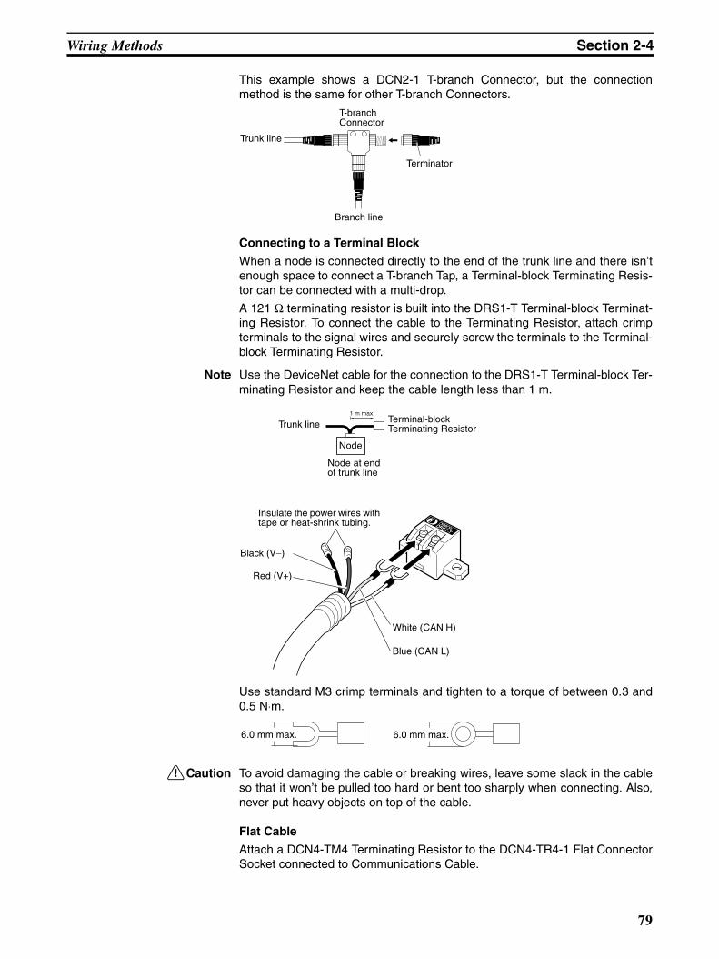
Wiring Methods Section 2-4
This example shows a DCN2-1 T-branch Connector, but the connectionmethod is the same for other T-branch Connectors.
Connecting to a Terminal Block
When a node is connected directly to the end of the trunk line and there isn’tenough space to connect a T-branch Tap, a Terminal-block Terminating Resis-tor can be connected with a multi-drop.
A 121 Ω terminating resistor is built into the DRS1-T Terminal-block Terminat-ing Resistor. To connect the cable to the Terminating Resistor, attach crimpterminals to the signal wires and securely screw the terminals to the Terminal-block Terminating Resistor.
Note Use the DeviceNet cable for the connection to the DRS1-T Terminal-block Ter-minating Resistor and keep the cable length less than 1 m.
Use standard M3 crimp terminals and tighten to a torque of between 0.3 and0.5 N⋅m.
!Caution To avoid damaging the cable or breaking wires, leave some slack in the cableso that it won’t be pulled too hard or bent too sharply when connecting. Also,never put heavy objects on top of the cable.
Flat Cable
Attach a DCN4-TM4 Terminating Resistor to the DCN4-TR4-1 Flat ConnectorSocket connected to Communications Cable.
Trunk line
Terminator
T-branch Connector
Branch line
1 m max.
Trunk line
Red (V+)
Black (V−)
White (CAN H)
Blue (CAN L)
Terminal-block Terminating Resistor
Node
Node at end of trunk line
Insulate the power wires with tape or heat-shrink tubing.
6.0 mm max. 6.0 mm max.
79

Wiring Methods Section 2-4
• Installation Method
Push in the Terminating Resistor until it clicks into place.
Note To remove a Terminating Resistor once it has been connected, pressin on the catches on both sides and pull it out.
To supply communications power from the terminal block, use a DCN4-TP4DFlat Cable Terminal Block with Terminating Resistance.
2-4-9 Grounding the NetworkUse any of the following methods to ground the network. The DeviceNet net-work must be grounded at one location and one location only.
Grounding the Shield (S) Terminal of a Power Supply Tap
Terminatingresistance
Flat Connector Socket
Black (V−)
Red (V+)
Flat Cable
DCN4-TP4D
S FGV−V+
V−V+
Trunk line
Communications power supply (24 V DC)
Trunk line
Power Supply Tap
80
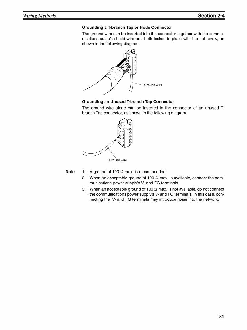
Wiring Methods Section 2-4
Grounding a T-branch Tap or Node Connector
The ground wire can be inserted into the connector together with the commu-nications cable’s shield wire and both locked in place with the set screw, asshown in the following diagram.
Grounding an Unused T-branch Tap Connector
The ground wire alone can be inserted in the connector of an unused T-branch Tap connector, as shown in the following diagram.
Note 1. A ground of 100 Ω max. is recommended.
2. When an acceptable ground of 100 Ω max. is available, connect the com-munications power supply’s V- and FG terminals.
3. When an acceptable ground of 100 Ω max. is not available, do not connectthe communications power supply’s V- and FG terminals. In this case, con-necting the V- and FG terminals may introduce noise into the network.
Ground wire
Ground wire
81

Minimizing Noise in the Network Section 2-5
2-5 Minimizing Noise in the Network
2-5-1 Precautions to Prevent Noise• To prevent inductive noise, separate the communications lines, PLC
power supply lines, and other power lines. In particular, be sure to keepthe power lines for inverters, motors, regulators, and contactors at least300 mm away from both the communications lines and the power supplylines. Also, provide separate conduits or ducts for the communicationslines and power lines.
• Make the power supply lines to the control panel as short as possible, useheavy-gauge wire, and ground the power supply properly (100 Ω max.)
• Avoid installing any DeviceNet devices in a control panel that containshigh-voltage devices.
• Install surge suppressors on devices that generate noise, particularlydevices that have an inductive component such as motors, transformers,solenoids, and magnetic coils.
• If a surge suppressor cannot be installed, installing a ferrite core directlynext to the device's contacts, such as a contactor may be effective.
• Noise emanating from the communications cable can be reduced byinstalling a ferrite core on the communications cable within 10 cm of theDeviceNet Master Unit.
300 mm min.
300 mm min.
1
2
21
21 2
1PLC power lines and general control circuit lines
Communications lines and PLC I/O lines
Power lines
Ground(100 Ω max.)
Suspended ducts
Floor ducts
Conduit
Power lines
Communications lines and PLC I/O lines
Low-voltage communications cables
Control cables
Power cables
Surge suppressor (just before device)
Surge suppressor (just before device)
Device (such as a motor)
Device (such as a motor)
DC Device AC Device
Ferrite core
Device (such as a motor)
82

Minimizing Noise in the Network Section 2-5
Ferrite Core (Data Line Filter):Nisshin Electric Co, Ltd. model 0443-164151 or equivalent
• Since noise currents often flow through metallic equipment (such as cas-ings), the communications cables should be placed as far away frommetallic equipment as possible.
• Ground the communications cable to 100 Ω max. with a ground wire thatis as short as possible.
• Ground the shielding wire on the communications cable at one point. Ifthe same ground is used for the communications cable and communica-tions power supply, there is a possibility that noise may be transmittedthrough the ground line to the communications line. In order to avoid this,be sure that the power line ground and the grounds for the communica-tions cables and the communications power supply are located as farfrom each other as possible.
• Insert a line filter on the primary side of the communications power sup-ply.
• When there are two or more communications power supplies, ground theshielding wire at the Power Supply Tap near the center of the communica-tions cable. Do not ground the shielding wire at more than one place.(In the following diagram, “PS” indicates a communications power supply.)
Note Do not connect the Power Supply Tap’s shield (S) terminal to the communica-tions power supply’s FG terminal at these two Power Supply Taps.
Inductance specifications
25 MHz 100 MHz
156 Ω 250 Ω
30 mm
29 mm
32 mm
13 mm
(See note.) (See note.)
Power Supply Tap, T-branch Tap, orT-branch Connector
Power Supply Taps
Power Supply Tap
Ground at one point
Master
Slave PSPS Slave PSPS Slave
Master
Network with 1 Communications Power Supply Network with 2 or more Communications Power Supplies
83
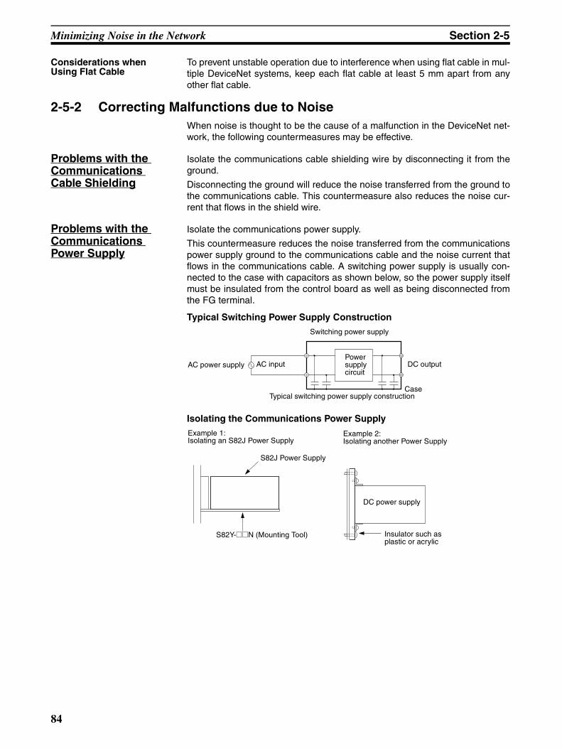
Minimizing Noise in the Network Section 2-5
Considerations when Using Flat Cable
To prevent unstable operation due to interference when using flat cable in mul-tiple DeviceNet systems, keep each flat cable at least 5 mm apart from anyother flat cable.
2-5-2 Correcting Malfunctions due to NoiseWhen noise is thought to be the cause of a malfunction in the DeviceNet net-work, the following countermeasures may be effective.
Problems with the Communications Cable Shielding
Isolate the communications cable shielding wire by disconnecting it from theground.
Disconnecting the ground will reduce the noise transferred from the ground tothe communications cable. This countermeasure also reduces the noise cur-rent that flows in the shield wire.
Problems with the Communications Power Supply
Isolate the communications power supply.
This countermeasure reduces the noise transferred from the communicationspower supply ground to the communications cable and the noise current thatflows in the communications cable. A switching power supply is usually con-nected to the case with capacitors as shown below, so the power supply itselfmust be insulated from the control board as well as being disconnected fromthe FG terminal.
Typical Switching Power Supply Construction
Isolating the Communications Power Supply
AC power supply AC input
Switching power supply
Power supply circuit
DC output
CaseTypical switching power supply construction
S82J Power Supply
S82Y-@@N (Mounting Tool)
DC power supply
Example 1:Isolating an S82J Power Supply
Example 2:Isolating another Power Supply
Insulator such as plastic or acrylic
84

Operational Checklist Section 2-6
2-6 Operational ChecklistCategory Item Check Result
Network configura-tion and wiring
Connectors Are the connectors and cables to the Master connected cor-rectly? (Do the wire colors match the colors next to the Mas-ter’s DeviceNet connector?)
Yes No
Are the connectors and cables to the Slaves connected cor-rectly? (Do the wire colors match the colors next to the Slaves’ DeviceNet connectors?)
Yes No
Are the connectors securely connected? Yes No
Is there a possibility that the cable connectors will be pulled out because of the cable weight?
Yes No
If the connectors have attachment screws or mounting brack-ets, are the screws/brackets tightened properly?
Yes No
Terminators Have Terminating Resistors been connected at both ends of the trunk line?
Yes No
Are the specified Terminating Resistors being used? Yes No
If a T-branch Tap is being terminated, is the Terminating Resistor seated properly in the T-branch Tap’s socket?
Yes No
Max. network length
Is the length of the network within specifications? Yes No
Branch line length
Are all branch lines 6 m or shorter? Yes No
Is the total branch line length within specifications? Yes No
Cables Can the cable supply the current required by all of the nodes that are connected?
Yes No
Is the proper DeviceNet cable being used? Yes No
Are the cables separated from any power or high-voltage lines?
Yes No
Have the cables been handled carefully, without excessive force?
Yes No
Shield wire ground
Is the network be grounded in only one location? Yes No
Is a separate ground line used? (Is the ground line separated from any power line ground?)
Yes No
Other Are there any devices in the network that are not DeviceNet products?
Yes No
Devices supplied by communications power supply
Power supply capacity
Has the power supply requirement been calculated using each node's current consumption?
Yes No
Can the power supply handle the inrush current when the sys-tem is started?
Yes No
Isolation Is the DC output isolated from the AC input in the power sup-ply?
Yes No
85

Operational Checklist Section 2-6
86

SECTION 3Communications Power Supply Methods
This section explains the various considerations involved in providing a communications power supply.
3-1 Basic Concepts . . . . . . . . . . . . . . . . . . . . . . . . . . . . . . . . . . . . . . . . . . . . . . . . 88
3-2 Flowchart: Determining Power Supply Requirements . . . . . . . . . . . . . . . . . . 89
3-2-1 Communications Power Supply . . . . . . . . . . . . . . . . . . . . . . . . . . . . 89
3-3 Locating the Power Supply . . . . . . . . . . . . . . . . . . . . . . . . . . . . . . . . . . . . . . . 90
3-3-1 Power Supply Layout Patterns . . . . . . . . . . . . . . . . . . . . . . . . . . . . . 90
3-3-2 Main Factors for Determining the Power Supply Location . . . . . . . 91
3-3-3 Calculating the Power Supply Location . . . . . . . . . . . . . . . . . . . . . . 91
3-4 Step 1: Evaluating the Configuration with Graphs . . . . . . . . . . . . . . . . . . . . . 92
3-4-1 Simple Evaluation of Power Supply Location from a Graph . . . . . . 93
3-4-2 Modifying the Configuration . . . . . . . . . . . . . . . . . . . . . . . . . . . . . . 93
3-5 Step 2: Evaluating the Configuration with Calculations. . . . . . . . . . . . . . . . . 96
3-5-1 Formulae for Calculating the Voltage Drop . . . . . . . . . . . . . . . . . . . 97
3-5-2 Modifying the Configuration . . . . . . . . . . . . . . . . . . . . . . . . . . . . . . 98
3-6 Step 3: Splitting the System into Multiple Power Supplies . . . . . . . . . . . . . . 101
3-6-1 Splitting the Power Supply System . . . . . . . . . . . . . . . . . . . . . . . . . 101
3-6-2 Configuration of the Power Supply Tap . . . . . . . . . . . . . . . . . . . . . . 101
3-6-3 Internal Circuits in the Power Supply Tap . . . . . . . . . . . . . . . . . . . . 101
87
Basic Concepts Section 3-1
3-1 Basic Concepts• The communications power supply must be 24 V DC.
• Always supply the power from the trunk line.
• When providing power to several nodes from one power supply, try tolocate the power supply near the center of the nodes.
• Provide power through Power Supply Taps. It is possible to use a T-branch Tap or T-branch Connector instead of a Power Supply Tap whenthere is one communications power supply in the system and the currentconsumption is within the specifications of the T-branch Tap or T-branchConnector. Refer to 2-3-4 T-branch Taps or 2-3-5 Shielded T-branch Con-nectors for details on the current limitations of these components.
• The power supply capacity for cables is restricted to 8 A for Thick Cables,3 A for Thin Cables, and 5 A for Flat Cables.
• Environment-resistive Slaves are wired with Thin Cable, so the currentthrough a cable to an Environment-resistive Slave is limited to 3 A.
• A single network is usually supplied by one power supply, however, it ispossible to have more than one power supply when power supply require-ments cannot be met with a single power supply. (See 3-6 Step 3: Split-ting the System into Multiple Power Supplies.)
• Provide some extra power supply capacity in the network to allow forfuture expansion and extend the life of the power supply.
• Turning OFF the communications power supply during operation cancause errors in the other nodes if the other power supplies are left ON.
• The current capacity of a branch line ranges from 0.75 to 3 A, dependingon its length. Use the following equation to calculate the current capacity.(The maximum current capacity of a branch line is 3 A, even if the branchline is shorter than 1.53 m.)
I = 4.57/L I: Permissible current (A)L: Length of the branch line (m)
88
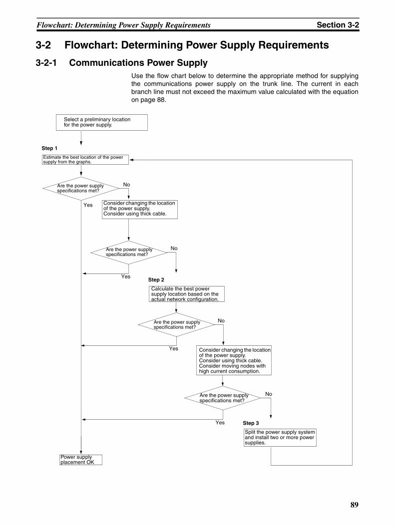
Flowchart: Determining Power Supply Requirements Section 3-2
3-2 Flowchart: Determining Power Supply Requirements
3-2-1 Communications Power Supply Use the flow chart below to determine the appropriate method for supplyingthe communications power supply on the trunk line. The current in eachbranch line must not exceed the maximum value calculated with the equationon page 88.
No
Yes
No
Yes
No
Yes
No
Yes
Select a preliminary location for the power supply.
Estimate the best location of the power supply from the graphs.
Step 1
Are the power supply specifications met?
Consider changing the location of the power supply.Consider using thick cable.
Calculate the best power supply location based on the actual network configuration.
Are the power supply specifications met?
Step 2
Are the power supply specifications met?
Consider changing the location of the power supply.Consider using thick cable.Consider moving nodes with high current consumption.
Are the power supply specifications met?
Step 3
Split the power supply system and install two or more power supplies.
Power supply placement OK
89

Locating the Power Supply Section 3-3
3-3 Locating the Power Supply
3-3-1 Power Supply Layout PatternsThe power supply can be set up in the configurations shown below. In gen-eral, select either configuration 1 or 2 (a single power supply configuration.)
Use configuration when power supply requirements cannot be met with con-figuration 1 or 2. For more details on each configuration, refer to sections 3-4Step 1: Evaluating the Configuration with Graphs through 3-6 Step 3: Splittingthe System into Multiple Power Supplies.
Configuration 1: Supplying Power to Nodes in Both Directions
Configuration 2: Supplying Power to Nodes in One Direction
Note (1) Configuration 1 is recommended when a single power supply is beingused to provide power to many nodes.
(2) When flat cable is used, power can be supplied from a DCN4-TP4D FlatCable Terminal Block with Terminating Resistance.
Configuration 3: Dividing the Power Supply System
Power Supply Tap or T-branch Tap
Node Node Node NodeNode Power supply
Power Supply Tap or T-branch Tap
NodeNode Node NodeNodePower supply
V+
V−
24 V 0 V
Power Supply Tap
NodeNode Node NodeNodePower supply
Power supply
Power Supply Tap
System 1 System 2
The V− line is shared by systems 1 and 2.
Remove fuse to cut off V+ in this direction.
Fuse
90

Locating the Power Supply Section 3-3
Note If the current carried by a thick cable exceeds 8 A even after the power supplyconfiguration has been changed, the power supply requirements cannot bemet with a single power supply and multiple power supplies must be used.
In configuration 1, the power can be supplied to the trunk line in both direc-tions as long as the current in each direction is 8 A or less when using thickcable. Consequently, it is possible to have a configuration with a total currentconsumption up to 16 A. Change to thick cable if thin cable is being used inthe trunk line and the current through the thin cable exceeds 3 A.
3-3-2 Main Factors for Determining the Power Supply LocationDetermine whether or not the current can be supplied normally by finding thecurrent capacity required by each node and the voltage drop in the cables tobe used to provide power. Calculate the values below in advance.
• The current required by each node
• The distance between the power supply and each node
3-3-3 Calculating the Power Supply LocationThere are two methods to find the best location of the communications powersupply on the trunk line.
1. Simple estimation from a graph
2. Calculation by formula (Calculate the voltage drop based on the current re-quirements of the nodes and the communications cable resistance.)
Each branch line must satisfy the equation on page 88, which shows themaximum current capacity of a branch line based on its length.
• The graph estimation assumes the worst case scenario from thestandpoint of the power supply (the configuration that has the maxi-mum voltage drop as shown in the diagram below), so any actual pow-er supply configuration will be acceptable based on the graphestimation.
• Since the graph estimation assumes the worst case scenario, an actu-al network configuration may be acceptable even if the configuration isdisallowed in the graph. Evaluate the configuration accurately by theperforming the calculations described in 3-5 Step 2: Evaluating theConfiguration with Calculations.
Note When a single power supply is used to provide the communications powersupply and the internal circuit supply, use the formula method to evaluate ahypothetical power supply location because it cannot be evaluated with thegraphs. Refer to Shared Communications and Internal Circuit Power Supplyon page 97 for details on this calculation.
Power Supply Tap
Power Supply
Node
Node
Node
Node
91

Step 1: Evaluating the Configuration with Graphs Section 3-4
3-4 Step 1: Evaluating the Configuration with GraphsThere is a voltage drop in a communications cable as current flows throughthe cable. The voltage drop increases in proportion to the length of the com-munications cable and the amperage of the current being carried.
The communications power supply at each node must be 11 V DC min. Thefollowing graph shows the maximum current that can be supplied through var-ious lengths of cable while maintaining the minimum voltage required at thenodes. (The values in the graph provide some extra margin.)
Thick Cable
Thin Cable
Distance (m) 0 25 50 100 150 200 250 300 350 400 450 500
Maximum current (A)
8.00 8.00 5.42 2.93 2.01 1.53 1.23 1.03 0.89 0.78 0.69 0.63
Distance (m) 0 10 20 30 40 50 60 70 80 90 100
Maximum current (A)
3.00 3.00 3.00 2.06 1.57 1.26 1.06 0.91 0.80 0.71 0.64
8
7
6
5
4
3
2
1
00 50 100 150 200 220 300 350 400 450 500
Max
imum
cur
rent
(A
)
Distance (m)
3
2
1
00 10 20 30 40 50 60 70 80 90 100
Max
imum
cur
rent
(A
)
Distance (m)
92

Step 1: Evaluating the Configuration with Graphs Section 3-4
Flat Cable
3-4-1 Simple Evaluation of Power Supply Location from a GraphCheck items 1 to 3 listed below for all of the nodes located in the same direc-tion from the power supply. (If power is supplied in two directions, check these3 items for all of the nodes in each direction.)
1,2,3... 1. Calculate the total current consumption (IA) of all the nodes to which com-munications power is to be supplied in one direction.
2. Refer to the graph to find the maximum current flow (IB) allowed in the ca-ble based on the type of cable being used (thick or thin) and the distancefrom the power supply to the end of the trunk line.
3. Compare the values (IA and IB) found in steps 1 and 2 above. If IA ≤ IB, thepower supply specifications are met and power can be supplied properlyto all nodes.
Note Be sure to refer to the correct graph because the maximum currentflow is different for thick and thin cables.
3-4-2 Modifying the ConfigurationIf the graph indicates that power cannot be supplied properly in one direction(IA > IB), use the following procedure to modify the communications powersupply configuration.
• Move the communications power supply towards the center of the net-work so that there are nodes to both sides of it.
• If there are already nodes on both sides of the power supply, move thepower supply in the direction that requires the higher current.
• If thin cable is being used, replace it with thick cable.
If power still cannot be supplied properly in one direction (IA > IB) after makingthe changes listed above, proceed to Step 2 and calculate the actual currentrequirements based on each node’s position in the network and its currentconsumption.
Distance (m) 0 20 40 80 100 140 200 260 300
Maximum current (A)
5.00 5.00 5.00 2.75 2.21 1.58 1.11 0.85 0.74
6
5
4
3
2
1
00 20 40 60 80 100 120 140 160 180 200 220 240 260 280 300
Max
imum
cur
rent
(A
)
Distance (m)
93
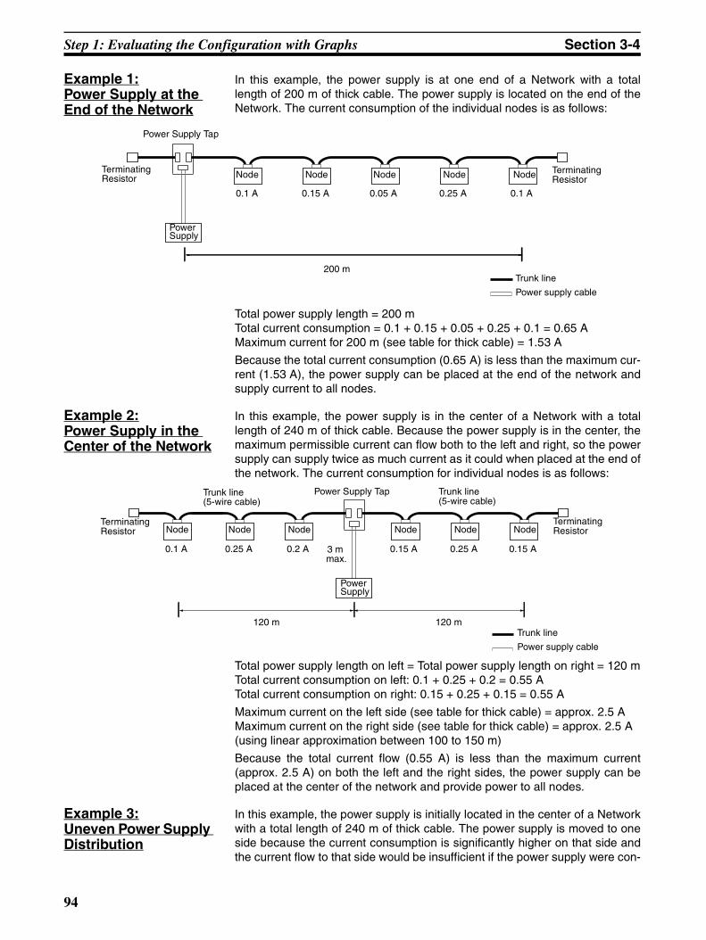
Step 1: Evaluating the Configuration with Graphs Section 3-4
Example 1:Power Supply at the End of the Network
In this example, the power supply is at one end of a Network with a totallength of 200 m of thick cable. The power supply is located on the end of theNetwork. The current consumption of the individual nodes is as follows:
Total power supply length = 200 mTotal current consumption = 0.1 + 0.15 + 0.05 + 0.25 + 0.1 = 0.65 AMaximum current for 200 m (see table for thick cable) = 1.53 A
Because the total current consumption (0.65 A) is less than the maximum cur-rent (1.53 A), the power supply can be placed at the end of the network andsupply current to all nodes.
Example 2:Power Supply in the Center of the Network
In this example, the power supply is in the center of a Network with a totallength of 240 m of thick cable. Because the power supply is in the center, themaximum permissible current can flow both to the left and right, so the powersupply can supply twice as much current as it could when placed at the end ofthe network. The current consumption for individual nodes is as follows:
Total power supply length on left = Total power supply length on right = 120 mTotal current consumption on left: 0.1 + 0.25 + 0.2 = 0.55 ATotal current consumption on right: 0.15 + 0.25 + 0.15 = 0.55 A
Maximum current on the left side (see table for thick cable) = approx. 2.5 AMaximum current on the right side (see table for thick cable) = approx. 2.5 A(using linear approximation between 100 to 150 m)
Because the total current flow (0.55 A) is less than the maximum current(approx. 2.5 A) on both the left and the right sides, the power supply can beplaced at the center of the network and provide power to all nodes.
Example 3:Uneven Power Supply Distribution
In this example, the power supply is initially located in the center of a Networkwith a total length of 240 m of thick cable. The power supply is moved to oneside because the current consumption is significantly higher on that side andthe current flow to that side would be insufficient if the power supply were con-
0.1 A 0.15 A 0.05 A 0.25 A 0.1 A
200 m
Terminating Resistor
Power Supply Tap
NodeNode NodeNodeNode
Trunk line
Terminating Resistor
Power supply cable
Power Supply
120 m 120 m
3 m max.
0.25 A 0.2 A 0.15 A 0.25 A 0.15 A0.1 A
Power Supply Tap
Power Supply
Node NodeNodeTerminating ResistorNode Node Node
Terminating Resistor
Trunk line
Power supply cable
Trunk line(5-wire cable)
Trunk line(5-wire cable)
94

Step 1: Evaluating the Configuration with Graphs Section 3-4
nected in the very center of the Network. Placing it slightly off center allowspower to be supplied properly to all nodes.The current consumption for individual nodes is as follows:
Total power supply length on left = Total power supply length on right = 120 mTotal current consumption on left: 1.1 + 1.25 + 0.5 = 2.85 ATotal current consumption on right: 0.25 + 0.25 + 0.85 = 1.35 A
Maximum current on the left side (see table for thick cable) = approx. 2.5 AMaximum current on the left side (see table for thick cable) = approx. 2.5 A(using straight line approximation between 100 to 150 m)
Because the total current flow on the left side (2.85 A) is greater than the max-imum current allowed on the left side (2.56 A), the power supply cannot sup-ply current to all nodes properly when it is placed at the center of the network.
This problem can be corrected by moving the communications power supplyas shown in the following diagram.
Total power supply length on left = 100 mTotal power supply length on right = 140 mTotal current consumption on left: 1.1 + 1.25 = 2.35 ATotal current consumption on right: 0.5 + 0.25 + 0.25 + 0.85 = 1.85 A
Maximum current for 100 m on the left (see table for thick cable) = 2.93 AMaximum current for 140 m on the right (see table for thick cable) = 2.1 A(using straight line approximation between 100 to 150 m)
Because the total current flow on both the left and right sides is now less thanthe allowed maximum current, the power supply can be placed as shown inthe diagram and supply current properly to all nodes.
120 m 120 m
3 mmax.
1.25 A 0.5 A 0.25 A 0.25 A 0.85 A1.1 A
Power Supply Tap
Power Supply
Node NodeNodeTerminating ResistorNode Node Node
Terminating Resistor
Trunk line
Power supply cable
Trunk line(5-wire cable)
Trunk line(5-wire cable)
100 m 140 m
3 mmax.
1.25 A 0.5 A 0.25 A 0.25 A 0.85 A1.1 A
Power Supply Tap
Power Supply
Node NodeNodeTerminating ResistorNode Node Node
Terminating Resistor
Trunk line
Power supply cable
Trunk line(5-wire cable)
Trunk line(5-wire cable)
95
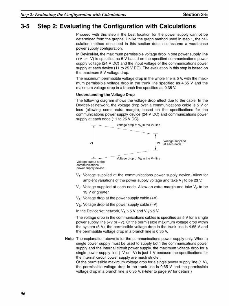
Step 2: Evaluating the Configuration with Calculations Section 3-5
3-5 Step 2: Evaluating the Configuration with CalculationsProceed with this step if the best location for the power supply cannot bedetermined from the graphs. Unlike the graph method used in step 1, the cal-culation method described in this section does not assume a worst-casepower supply configuration.
In DeviceNet, the maximum permissible voltage drop in one power supply line(+V or −V) is specified as 5 V based on the specified communications powersupply voltage (24 V DC) and the input voltage of the communications powersupply at each device (11 to 25 V DC). The evaluation in this step is based onthe maximum 5 V voltage drop.
The maximum permissible voltage drop in the whole line is 5 V, with the maxi-mum permissible voltage drop in the trunk line specified as 4.65 V and themaximum voltage drop in a branch line specified as 0.35 V.
Understanding the Voltage Drop
The following diagram shows the voltage drop effect due to the cable. In theDeviceNet network, the voltage drop over a communications cable is 5 V orless (allowing some extra margin), based on the specifications for thecommunications power supply device (24 V DC) and communications powersupply at each node (11 to 25 V DC).
V1: Voltage supplied at the communications power supply device. Allow forambient variations of the power supply voltage and take V1 to be 23 V.
V2: Voltage supplied at each node. Allow an extra margin and take V2 to be13 V or greater.
VA: Voltage drop at the power supply cable (+V).
VB: Voltage drop at the power supply cable (−V).
In the DeviceNet network, VA ≤ 5 V and VB ≤ 5 V.
The voltage drop in the communications cables is specified as 5 V for a singlepower supply line (+V or −V). Of the permissible maximum voltage drop withinthe system (5 V), the permissible voltage drop in the trunk line is 4.65 V andthe permissible voltage drop in a branch line is 0.35 V.
Note The explanation above is for the communications power supply only. When asingle power supply must be used to supply both the communications powersupply and the internal circuit power supply, the maximum voltage drop for asingle power supply line (+V or −V) is just 1 V because the specifications forthe internal circuit power supply are much stricter.Of the permissible maximum voltage drop for a single power supply line (1 V),the permissible voltage drop in the trunk line is 0.65 V and the permissiblevoltage drop in a branch line is 0.35 V. (Refer to page 97 for details.)
V1 V2
Voltage drop of VA in the V+ line
Voltage drop of VB in the V− lineVoltage output at the communications power supply device.
Voltage supplied at each node.
96

Step 2: Evaluating the Configuration with Calculations Section 3-5
3-5-1 Formulae for Calculating the Voltage Drop
Independent Communications and Internal Circuit Power SuppliesDetermine the distance between the power supply and each node, and eachnode's current consumption for communications. (Refer to the table showingcurrent consumption for various devices in Appendix C Current Consumptionof DeviceNet Devices.) Evaluate whether the configuration satisfies the for-mula below. If the voltage drop is within the maximum value indicated, powercan be supplied to the nodes properly with the configuration. Of course thecurrent cannot exceed the maximum current capacity of the cable (8 A forthick cable and 3 A for thin cable.)
Formula 1: Calculating the Voltage Drop in the Trunk Line
Σ (Ln × Rc + Nt × 0.005) × In ≤ 4.65 V
Ln: The distance between the power supply and node n (not including thelength of the branch line)
Rc: Maximum cable resistance(Thick cable: 0.015 Ω/m, thin cable: 0.069 Ω/m])
Nt: The number of Taps between node n and the power supply(0.005 Ω = The contact resistance of a Tap)
In: The communications current required by node n
Shared Communications and Internal Circuit Power Supply
Note We recommend using separate power supplies for the communications powerand the internal circuit power. (For details, refer to 2-2-9 Sharing the Commu-nications and Internal Circuit Power Supply.)
The allowed voltage ranges for the communications power supply and internalcircuit power supply are significantly different, as shown below.
Communications power supply voltage range: 11 to 25 V DCInternal circuit power supply voltage range: 24 V DC +10% to −15%
The lowest permissible voltage is 11 V DC for the communications power sup-ply, whereas it is 21 V DC (including the extra margin) for the internal circuitpower supply. If the internal circuit power is supplied by the communicationspower supply, the maximum permissible voltage drop due to cable resistanceis much lower than it would be if the power supplies were separate.
When the output voltage fluctuation of the communications power supply istaken into account and 23 V (the lower end of the fluctuation range) is used asthe power supply output voltage, the maximum permissible voltage drop in asingle power supply line is (23 V − 21 V) /2 = 1 V. The permissible voltagedrop can be subdivided into the max. permissible voltage drop in the trunk lineof 0.65 V and the max. permissible voltage drop in a branch line of 0.35 V.
Determine the distance between the power supply and each node, and thetotal current consumption (communications and internal circuit power) foreach node. There’s no need to take into account the internal power supplycurrent consumption of the Master Unit. (Refer to the table showing currentconsumption for various devices in Appendix C Current Consumption ofDeviceNet Devices.)
Evaluate whether the power supply configuration satisfies the formula below.If the voltage drop is within the maximum value indicated, power can be sup-plied to the nodes properly with the configuration. Of course the current can-not exceed the maximum current capacity of the cable (8 A for thick cable and3 A for thin cable.)
97
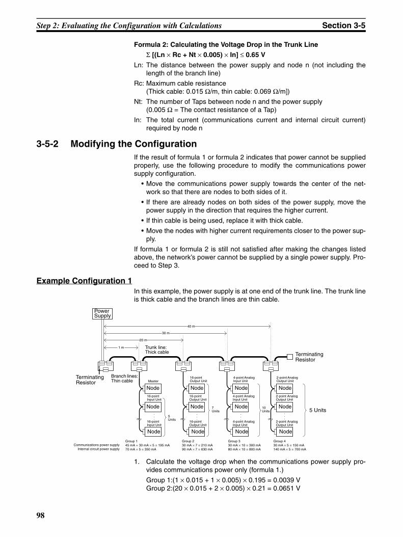
Step 2: Evaluating the Configuration with Calculations Section 3-5
Formula 2: Calculating the Voltage Drop in the Trunk Line
Σ [(Ln × Rc + Nt × 0.005) × In] ≤ 0.65 V
Ln: The distance between the power supply and node n (not including thelength of the branch line)
Rc: Maximum cable resistance(Thick cable: 0.015 Ω/m, thin cable: 0.069 Ω/m])
Nt: The number of Taps between node n and the power supply(0.005 Ω = The contact resistance of a Tap)
In: The total current (communications current and internal circuit current)required by node n
3-5-2 Modifying the ConfigurationIf the result of formula 1 or formula 2 indicates that power cannot be suppliedproperly, use the following procedure to modify the communications powersupply configuration.
• Move the communications power supply towards the center of the net-work so that there are nodes to both sides of it.
• If there are already nodes on both sides of the power supply, move thepower supply in the direction that requires the higher current.
• If thin cable is being used, replace it with thick cable.
• Move the nodes with higher current requirements closer to the power sup-ply.
If formula 1 or formula 2 is still not satisfied after making the changes listedabove, the network’s power cannot be supplied by a single power supply. Pro-ceed to Step 3.
Example Configuration 1In this example, the power supply is at one end of the trunk line. The trunk lineis thick cable and the branch lines are thin cable.
1. Calculate the voltage drop when the communications power supply pro-vides communications power only (formula 1.)
Group 1:(1 × 0.015 + 1 × 0.005) × 0.195 = 0.0039 VGroup 2:(20 × 0.015 + 2 × 0.005) × 0.21 = 0.0651 V
1 m
20 m
30 m
40 m
.
.
.
.
.
.
.
.
....
Group 145 mA + 30 mA × 5 = 195 mA70 mA × 5 = 350 mA
Group 230 mA × 7 = 210 mA90 mA × 7 = 630 mA
Group 330 mA × 10 = 300 mA80 mA × 10 = 800 mA
Group 430 mA × 5 = 150 mA140 mA × 5 = 700 mA
Power Supply
Node
Terminating Resistor
NodeNode Node
Terminating Resistor
Trunk line: Thick cable
Node NodeNode Node
Node NodeNode Node
16-point Input Unit
Master
16-point Input Unit
16-point Output Unit
16-point Output Unit
16-point Output Unit
4-point Analog Input Unit
4-point Analog Input Unit
4-point Analog Input Unit
2-point Analog Output Unit
2-point Analog Output Unit
2-point Analog Output Unit
5 Units
Communications power supplyInternal circuit power supply
Branch lines: Thin cable
10 Units
7 Units
5 Units
98

Step 2: Evaluating the Configuration with Calculations Section 3-5
Group 3:(30 × 0.015 + 3 × 0.005) × 0.30 = 0.1395 VGroup 4:(40 × 0.015 + 4 × 0.005) × 0.15 = 0.093 VTotal voltage drop = 0.0039 + 0.0651 + 0.1395 + 0.093 = 0.3015 V ≤ 4.65 V
In this case, formula 1 is satisfied, so the power supply can supply just thecommunications power.
2. Calculate the voltage drop when the communications power supply pro-vides both communications power and internal circuit power (formula 2.)
Group 1:(1 × 0.015 + 1 × 0.005) × 0.545 = 0.0109 VGroup 2:(20 × 0.015 + 2 × 0.005) × 0.84 = 0.2604 VGroup 3:(30 × 0.015 + 3 × 0.005) × 1.1 = 0.5115 VGroup 4:(40 × 0.015 + 4 × 0.005) × 0.85 = 0.527 VTotal voltage drop = 0.0109 + 0.2604 + 0.5115 + 0.527 = 1.3098 V ≥ 0.65 V
In this case, formula 2 is not satisfied, so the power supply cannot supplythe communications power and internal circuit power.
Example Configuration 2In this example, the power supply is near the middle of the trunk line. Thetrunk line is thick cable and the branch lines are thin cable.
1. Calculate the voltage drop when the communications power supply pro-vides communications power only (formula 1.)
a) System 1 (Left Side)
Group 1:(20 × 0.015 + 2 × 0.005) × 0.255 = 0.0791 VGroup 2:(10 × 0.015 + 1 × 0.005) × 0.3 = 0.0465 VTotal voltage drop = 0.0791 + 0.0465 = 0.1256 V ≤ 4.65 V
In this case, formula 1 is satisfied on the left side.
b) System 2 (Right Side)
Group 3:(10 × 0.015 + 1 × 0.005) × 0.15 = 0.0233 VGroup 4:(30 × 0.015 + 2 × 0.005) × 0.15 = 0.069 VTotal voltage drop = 0.0233 + 0.069 = 0.0923 V ≤ 4.65 V
In this case, formula 1 is satisfied on the right side.
2. Calculate the voltage drop when the communications power supply pro-vides both communications power and internal circuit power (formula 2.)
a) System 1 (Left Side)
.
.
.
20 m
10 m 10 m
30 m...
.
.
.
.
.
.
Group 145 mA + 30 mA × 7 = 255 mA90 mA × 7 = 630 mA
Group 230 mA × 10 = 300 mA80 mA × 10 = 800 mA
Group 330 mA × 5 = 150 mA70 mA × 5 = 350 mA
Group 430 mA × 5 = 150 mA140 mA × 5 = 700 mA
Power Supply
Node
Terminating Resistor
Node
Terminating Resistor
Trunk line: Thick cable
Node Node
Node Node
Master
16-point Input Unit
16-point Input Unit
16-point Input Unit
Branch lines: Thin cable
5Units
4-point Analog Input Unit
4-point Analog Input Unit
4-point Analog Input Unit
16-point Output Unit
16-point Output Unit
5Units
10Units7
Units
System 1 System 2
Node
Node
Node
Node
Node
Node
2-point Analog Output Unit
2-point Analog Output Unit
2-point Analog Output Unit
99

Step 2: Evaluating the Configuration with Calculations Section 3-5
Group 1:(20 × 0.015 + 2 × 0.005) × 0.885 = 0.2744 VGroup 2:(10 × 0.015 + 1 × 0.005) × 1.1 = 0.1705 VTotal voltage drop = 0.2744 + 0.1705 = 0.4449 V ≤ 0.65 V
In this case, formula 2 is satisfied on the left side.
b) System 2 (Right Side)
Group 3:(10 × 0.015 + 1 × 0.005) × 0.5 = 0.0775 VGroup 4:(30 × 0.015 + 2 × 0.005) × 0.85 = 0.391 VTotal voltage drop = 0.0775 + 0.391 = 0.4685 V ≤ 0.65 V
In this case, formula 2 is satisfied on the right side.
100
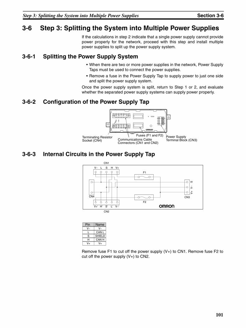
Step 3: Splitting the System into Multiple Power Supplies Section 3-6
3-6 Step 3: Splitting the System into Multiple Power SuppliesIf the calculations in step 2 indicate that a single power supply cannot providepower properly for the network, proceed with this step and install multiplepower supplies to split up the power supply system.
3-6-1 Splitting the Power Supply System• When there are two or more power supplies in the network, Power Supply
Taps must be used to connect the power supplies.
• Remove a fuse in the Power Supply Tap to supply power to just one sideand split the power supply system.
Once the power supply system is split, return to Step 1 or 2, and evaluatewhether the separated power supply systems can supply power properly.
3-6-2 Configuration of the Power Supply Tap
3-6-3 Internal Circuits in the Power Supply Tap
Remove fuse F1 to cut off the power supply (V+) to CN1. Remove fuse F2 tocut off the power supply (V+) to CN2.
Terminating Resistor Socket (CN4)
Power Supply Terminal Block (CN3)Communications Cable
Connectors (CN1 and CN2)
Fuses (F1 and F2)
V−LSHV+
V−CAN L
SHIELDCAN H
V+
CN2
CN3
F2
F1
CN1
V−'L'S'
SV
−V
+
H'V+'
V+HSL
CN4
V−
Pin Name
101

Step 3: Splitting the System into Multiple Power Supplies Section 3-6
102

Appendix AConnectable Device Lists
Master Units
Configurator
Model Specifications
CS1W-DRM21(-V1) For CS-series PLCs
CJ1W-DRM21 For CJ-series PLCs
CVM1-DRM21-V1 For CVM1 and CV-series PLCs
C200HW-DRM21-V1 For CS-series, C200HX/HG/HE, and C200HS PLCs
3G8F7-DRM21 PCI Board
3G8B3-DRM21 VME Board
Model Specifications
WS02-CFDC1-E Configurator Software Version 2.@3G8E2-DRM21-V1 Configurator Software Version 2.@ (Included with the PCMCIA Card.)
103

Connectable Device Lists Appendix A
Slave Units
DRT2-series General-purpose Slaves Model Specifications
DRT2-ID08 Remote I/O Terminal with 8 transistor inputs (NPN)
DRT2-ID08-1 Remote I/O Terminal with 8 transistor inputs (PNP)
DRT2-ID16 Remote I/O Terminal with 16 transistor inputs (NPN)
DRT2-ID16-1 Remote I/O Terminal with 16 transistor inputs (PNP)
DRT2-OD08 Remote I/O Terminal with 8 transistor outputs (NPN)
DRT2-OD08-1 Remote I/O Terminal with 8 transistor outputs (PNP)
DRT2-OD16 Remote I/O Terminal with 16 transistor outputs (NPN)
DRT2-OD16-1 Remote I/O Terminal with 16 transistor outputs (PNP)
DRT2-MD16 Remote I/O Terminal with 8 transistor inputs and 8 transistor outputs (NPN)
DRT2-MD16-1 Remote I/O Terminal with 8 transistor inputs and 8 transistor outputs (PNP)
DRT2-ROS16 Remote I/O Terminal with 16 relay outputs
XWT-ID16 Remote I/O Terminal Expansion Unit with 16 transistor inputs (NPN)
XWT-ID16-1 Remote I/O Terminal Expansion Unit with 16 transistor inputs (PNP)
XWT-OD16 Remote I/O Terminal Expansion Unit with 16 transistor outputs (NPN)
XWT-OD16-1 Remote I/O Terminal Expansion Unit with 16 transistor outputs (PNP)
XWT-ID08 Remote I/O Terminal Expansion Unit with 8 transistor inputs (NPN)
XWT-ID08-1 Remote I/O Terminal Expansion Unit with 8 transistor inputs (PNP)
XWT-OD08 Remote I/O Terminal Expansion Unit with 8 transistor outputs (NPN)
XWT-OD08-1 Remote I/O Terminal Expansion Unit with 8 transistor outputs (PNP)
DRT2-ID16TA Remote I/O Terminal with 3-tier terminal blocks and 16 transistor inputs (NPN)
DRT2-ID16TA-1 Remote I/O Terminal with 3-tier terminal blocks and 16 transistor inputs (PNP)
DRT2-OD16TA Remote I/O Terminal with 3-tier terminal blocks and 16 transistor outputs (NPN)
DRT2-OD16TA-1 Remote I/O Terminal with 3-tier terminal blocks and 16 transistor outputs (PNP)
DRT2-MD16TA Remote I/O Terminal with 3-tier terminal blocks and 8 transistor inputs/8 transistor outputs (NPN)
DRT2-MD16TA-1 Remote I/O Terminal with 3-tier terminal blocks and 8 transistor inputs/8 transistor outputs (PNP)
DRT2-ID16S Sensor Connector Terminal with 16-point Transistor Input (NPN)
DRT2-ID16S-1 Sensor Connector Terminal with 16-point Transistor Input (PNP)
DRT2-MD16S Sensor Connector Terminal with 8 transistor inputs and 8 transistor outputs (NPN)
DRT2-MD16S-1 Sensor Connector Terminal with 8 transistor inputs and 8 transistor outputs (PNP)
DRT2-ID16ML MIL Connector Terminal with 16 transistor inputs (NPN)
DRT2-ID16ML-1 MIL Connector Terminal with 16 transistor inputs (PNP)
DRT2-ID16MLX MIL Connector Terminal with 16 transistor inputs (NPN), cable with connectors included
DRT2-ID16MLX-1 MIL Connector Terminal with 16 transistor inputs (PNP), cable with connectors included
DRT2-ID32ML MIL Connector Terminal with 32 transistor inputs (NPN)
DRT2-ID32ML-1 MIL Connector Terminal with 32 transistor inputs (PNP)
DRT2-OD16ML MIL Connector Terminal with 16 transistor outputs (NPN)
DRT2-OD16ML-1 MIL Connector Terminal with 16 transistor outputs (PNP)
DRT2-OD16MLX MIL Connector Terminal with 16 transistor outputs (NPN), cable with connectors included
DRT2-OD16MLX-1 MIL Connector Terminal with 16 transistor outputs (PNP), cable with connectors included
DRT2-OD32ML MIL Connector Terminal with 32 transistor outputs (NPN)
DRT2-OD32ML-1 MIL Connector Terminal with 32 transistor outputs (PNP)
DRT2-MD32ML MIL Connector Terminal with 16 transistor inputs/16 transistor outputs (NPN)
DRT2-MD32ML-1 MIL Connector Terminal with 16 transistor inputs/16 transistor outputs (PNP)
DRT2-ID32B Board MIL Connector Terminal with connector parallel to board and with 32 transistor inputs (NPN)
DRT2-ID32B-1 Board MIL Connector Terminal with connector parallel to board and with 32 transistor inputs (PNP)
104

Connectable Device Lists Appendix A
DRT2-OD32B Board MIL Connector Terminal with connector parallel to board and with 32 transistor outputs (NPN)
DRT2-OD32B-1 Board MIL Connector Terminal with connector parallel to board and with 32 transistor outputs (PNP)
DRT2-MD32B Board MIL Connector Terminal with connector parallel to board and with16 transistor inputs/16 transistor outputs (NPN)
DRT2-MD32B-1 Board MIL Connector Terminal with connector parallel to board and with 16 transistor inputs/16 transistor outputs (PNP)
DRT2-ID32BV Board MIL Connector Terminal with connector perpendicular to board and with 32 transistor inputs (NPN)
DRT2-ID32BV-1 Board MIL Connector Terminal with connector perpendicular to board and with 32 transistor inputs (PNP)
DRT2-OD32BV Board MIL Connector Terminal with connector perpendicular to board and with 32 transistor out-puts (NPN)
DRT2-OD32BV-1 Board MIL Connector Terminal with connector perpendicular to board and with 32 transistor out-puts (PNP)
DRT2-MD32BV Board MIL Connector Terminal with connector perpendicular to board and with16 transistor inputs/16 transistor outputs (NPN)
DRT2-MD32BV-1 Board MIL Connector Terminal with connector perpendicular to board and with 16 transistor inputs/16 transistor outputs (PNP)
DRT2-ID16SL Screw-less Clamp Terminal with 16 transistor inputs and no detection functions (NPN)
DRT2-ID16SL-1 Screw-less Clamp Terminal with 16 transistor inputs and no detection functions (PNP)
DRT2-OD16SL Screw-less Clamp Terminal with 16 transistor outputs and no detection functions (NPN)
DRT2-OD16SL-1 Screw-less Clamp Terminal with 16 transistor outputs and no detection functions (PNP)
DRT2-ID16SLH Screw-less Clamp Terminal with 16 transistor inputs and detection functions (NPN)
DRT2-ID16SLH-1 Screw-less Clamp Terminal with 16 transistor inputs and detection functions (PNP)
DRT2-OD16SLH Screw-less Clamp Terminal with 16 transistor outputs and detection functions (NPN)
DRT2-OD16SLH-1 Screw-less Clamp Terminal with 16 transistor outputs and detection functions (PNP)
DRT2-ID32SL Screw-less Clamp Terminal with 32 transistor inputs and no detection functions (NPN)
DRT2-ID32SL-1 Screw-less Clamp Terminal with 32 transistor inputs and no detection functions (PNP)
DRT2-OD32SL Screw-less Clamp Terminal with 32 transistor outputs and no detection functions (NPN)
DRT2-OD32SL-1 Screw-less Clamp Terminal with 32 transistor outputs and no detection functions (PNP)
DRT2-MD32SL Screw-less Clamp Terminal with 16 transistor inputs, 16 transistor outputs, and no detection func-tions (NPN)
DRT2-MD32SL-1 Screw-less Clamp Terminal with 16 transistor inputs, 16 transistor outputs, and no detection func-tions (PNP)
DRT2-ID32SLH Screw-less Clamp Terminal with 32 transistor inputs and detection functions (NPN)
DRT2-ID32SLH-1 Screw-less Clamp Terminal with 32 transistor inputs and detection functions (PNP)
DRT2-OD32SLH Screw-less Clamp Terminal with 32 transistor outputs and detection functions (NPN)
DRT2-OD32SLH-1 Screw-less Clamp Terminal with 32 transistor outputs and detection functions (PNP)
DRT2-MD32SLH Screw-less Clamp Terminal with 16 transistor inputs, 16 transistor outputs, and detection functions (NPN)
DRT2-MD32SLH-1 Screw-less Clamp Terminal with 16 transistor inputs, 16 transistor outputs, and detection functions (PNP)
Model Specifications
105

Connectable Device Lists Appendix A
DRT1-series General-purpose SlavesModel Specifications
DRT1-ID08 I/O Terminal with 8 transistor inputs (NPN)
DRT1-ID08-1 I/O Terminal with 8 transistor inputs (PNP)
DRT1-ID16 I/O Terminal with 16 transistor inputs (NPN)
DRT1-ID16-1 I/O Terminal with 16 transistor inputs (PNP)
DRT1-OD08 I/O Terminal with 8 transistor outputs (NPN)
DRT1-OD08-1 I/O Terminal with 8 transistor outputs (PNP)
DRT1-OD16 I/O Terminal with 16 transistor outputs (NPN)
DRT1-OD16-1 I/O Terminal with 16 transistor outputs (PNP)
DRT1-MD16 I/O Terminal with 8 transistor inputs and 8 transistor outputs (NPN)
DRT1-ID16T I/O Terminal with 16 transistor inputs (NPN), Three-tier Terminal Block type
DRT1-ID16T-1 I/O Terminal with 16 transistor inputs (PNP), Three-tier Terminal Block type
DRT1-OD16T I/O Terminal with 16 transistor outputs (NPN), Three-tier Terminal Block type
DRT1-OD16T-1 I/O Terminal with 16 transistor outputs (PNP), Three-tier Terminal Block type
DRT1-MD16T I/O Terminal with 8 transistor inputs and 8 transistor outputs (NPN), Three-tier Terminal Block type
DRT1-MD16T-1 I/O Terminal with 8 transistor inputs and 8 transistor outputs (PNP), Three-tier Terminal Block type
DRT1-ID16TA I/O Terminal with 16 transistor inputs (NPN), Three-tier Terminal Block type (Internal power supply not required.)
DRT1-ID16TA-1 I/O Terminal with 16 transistor inputs (PNP), Three-tier Terminal Block type (Internal power supply not required.)
DRT1-OD16TA I/O Terminal with 16 transistor outputs (NPN), Three-tier Terminal Block type (Internal power sup-ply not required.)
DRT1-OD16TA-1 I/O Terminal with 16 transistor outputs (PNP), Three-tier Terminal Block type (Internal power supply not required.)
DRT1-MD16TA I/O Terminal with 8 transistor inputs and 8 transistor outputs (NPN), Three-tier Terminal Block type (Internal power supply not required.)
DRT1-MD16TA-1 I/O Terminal with 8 transistor inputs and 8 transistor outputs (PNP), Three-tier Terminal Block type (Internal power supply not required.)
DRT1-ID32ML I/O Terminal with 32 transistor inputs (NPN) with connector (Internal power supply not required.)
DRT1-ID32ML-1 I/O Terminal with 32 transistor inputs (PNP) with connector (Internal power supply not required.)
DRT1-OD32ML I/O Terminal with 32 transistor outputs (NPN) with connector (Internal power supply not required.)
DRT1-OD32ML-1 I/O Terminal with 32 transistor outputs (PNP) with connector (Internal power supply not required.)
DRT1-MD32ML I/O Terminal with 16 transistor outputs and 16 transistor outputs (NPN) with connector (Internal power supply not required.)
DRT1-MD32ML-1 I/O Terminal with 16 transistor outputs and 16 transistor outputs (PNP) with connector (Internal power supply not required.)
DRT1-ID16X Remote Adapter with 16 transistor inputs (NPN)
DRT1-ID16X-1 Remote Adapter with 16 transistor inputs (PNP)
DRT1-OD16X Remote Adapter with 16 transistor outputs (NPN)
DRT1-OD16X-1 Remote Adapter with 16 transistor outputs (PNP)
DRT1-HD16S Sensor Terminal with 8 sensor inputs (NPN), 2 inputs per sensor
DRT1-ND16S Sensor Terminal with 8 sensor inputs/outputs (NPN), 1 input and 1 output per sensor
CQM1-DRT21 I/O Link Unit for CQM1 PLCs with 16 inputs and 16 outputs
CPM1A-DRT21 I/O Link Unit for CPM1A/CPM2A PLCs with 32 inputs and 32 outputs
106

Connectable Device Lists Appendix A
DRT2-series Environment-resistive SlavesModel Specifications
DRT2-ID08C Environment-resistive Terminal with 8 transistor inputs (NPN), meets IEC IP67 standards
DRT2-ID08C-1 Environment-resistive Terminal with 8 transistor inputs (PNP), meets IEC IP67 standards
DRT2-HD16C Environment-resistive Terminal with 16 transistor inputs (NPN), meets IEC IP67 standards
DRT2-HD16C-1 Environment-resistive Terminal with 16 transistor inputs (PNP), meets IEC IP67 standards
DRT2-OD08C Environment-resistive Terminal with 8 transistor outputs (NPN), meets IEC IP67 standards
DRT2-OD08C-1 Environment-resistive Terminal with 8 transistor outputs (PNP), meets IEC IP67 standards
DRT2-ID04CL Standard Environment-resistive Terminal with 4 transistor inputs (NPN)Conforms to IEC IP67
DRT2-ID04CL-1 Standard Environment-resistive Terminal with 4 transistor inputs (PNP)Conforms to IEC IP67
DRT2-ID08CL Standard Environment-resistive Terminal with 8 transistor inputs (NPN)
Conforms to IEC IP67
DRT2-ID08CL-1 Standard Environment-resistive Terminal with 8 transistor inputs (PNP)
Conforms to IEC IP67
DRT2-HD16CL Standard Environment-resistive Terminal with 16 transistor inputs (NPN)Conforms to IEC IP67
DRT2-HD16CL-1 Standard Environment-resistive Terminal with 16 transistor inputs (PNP)Conforms to IEC IP67
DRT2-OD04CL Standard Environment-resistive Terminal with 4 transistor outputs (NPN)Conforms to IEC IP67
DRT2-OD04CL-1 Standard Environment-resistive Terminal with 4 transistor outputs (PNP)Conforms to IEC IP67
DRT2-OD08CL Standard Environment-resistive Terminal with 8 transistor outputs (NPN)
Conforms to IEC IP67
DRT2-OD08CL-1 Standard Environment-resistive Terminal with 8 transistor outputs (PNP)
Conforms to IEC IP67
DRT2-WD16CL Standard Environment-resistive Terminal with 16 transistor outputs (NPN)
Conforms to IEC IP67
DRT2-WD16CL-1 Standard Environment-resistive Terminal with 16 transistor outputs (PNP)Conforms to IEC IP67
DRT2-MD16CL Standard Environment-resistive Terminal with 8 transistor inputs /8 transistor outputs (NPN)Conforms to IEC IP67
DRT2-MD16CL-1 Standard Environment-resistive Terminal with 8 transistor inputs /8 transistor outputs (PNP)Conforms to IEC IP67
107
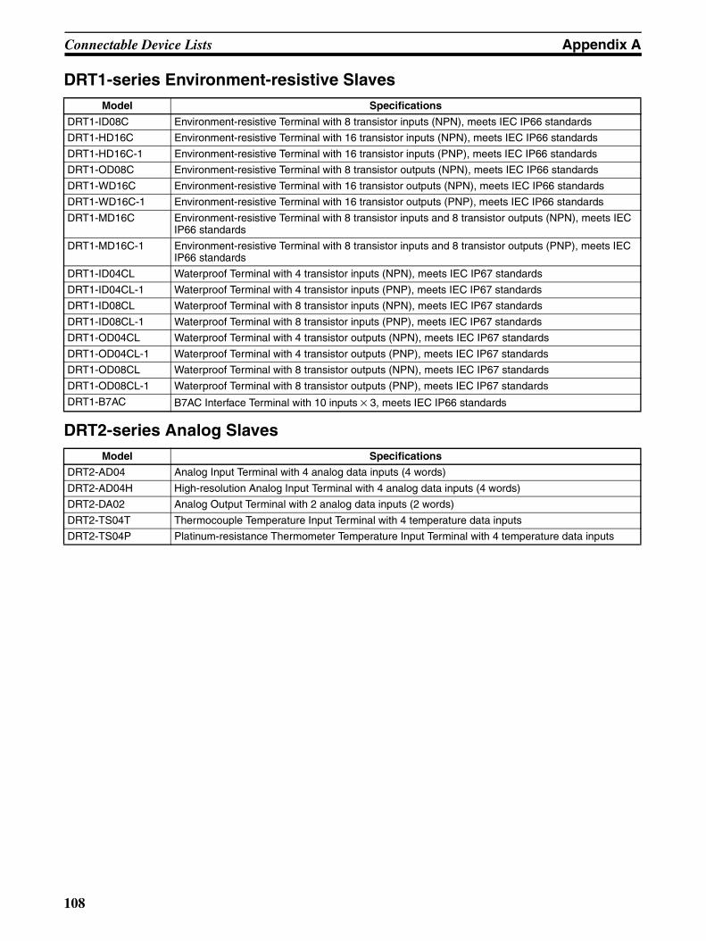
Connectable Device Lists Appendix A
DRT1-series Environment-resistive Slaves
DRT2-series Analog Slaves
Model Specifications
DRT1-ID08C Environment-resistive Terminal with 8 transistor inputs (NPN), meets IEC IP66 standards
DRT1-HD16C Environment-resistive Terminal with 16 transistor inputs (NPN), meets IEC IP66 standards
DRT1-HD16C-1 Environment-resistive Terminal with 16 transistor inputs (PNP), meets IEC IP66 standards
DRT1-OD08C Environment-resistive Terminal with 8 transistor outputs (NPN), meets IEC IP66 standards
DRT1-WD16C Environment-resistive Terminal with 16 transistor outputs (NPN), meets IEC IP66 standards
DRT1-WD16C-1 Environment-resistive Terminal with 16 transistor outputs (PNP), meets IEC IP66 standards
DRT1-MD16C Environment-resistive Terminal with 8 transistor inputs and 8 transistor outputs (NPN), meets IEC IP66 standards
DRT1-MD16C-1 Environment-resistive Terminal with 8 transistor inputs and 8 transistor outputs (PNP), meets IEC IP66 standards
DRT1-ID04CL Waterproof Terminal with 4 transistor inputs (NPN), meets IEC IP67 standards
DRT1-ID04CL-1 Waterproof Terminal with 4 transistor inputs (PNP), meets IEC IP67 standards
DRT1-ID08CL Waterproof Terminal with 8 transistor inputs (NPN), meets IEC IP67 standards
DRT1-ID08CL-1 Waterproof Terminal with 8 transistor inputs (PNP), meets IEC IP67 standards
DRT1-OD04CL Waterproof Terminal with 4 transistor outputs (NPN), meets IEC IP67 standards
DRT1-OD04CL-1 Waterproof Terminal with 4 transistor outputs (PNP), meets IEC IP67 standards
DRT1-OD08CL Waterproof Terminal with 8 transistor outputs (NPN), meets IEC IP67 standards
DRT1-OD08CL-1 Waterproof Terminal with 8 transistor outputs (PNP), meets IEC IP67 standards
DRT1-B7AC B7AC Interface Terminal with 10 inputs × 3, meets IEC IP66 standards
Model Specifications
DRT2-AD04 Analog Input Terminal with 4 analog data inputs (4 words)
DRT2-AD04H High-resolution Analog Input Terminal with 4 analog data inputs (4 words)
DRT2-DA02 Analog Output Terminal with 2 analog data inputs (2 words)
DRT2-TS04T Thermocouple Temperature Input Terminal with 4 temperature data inputs
DRT2-TS04P Platinum-resistance Thermometer Temperature Input Terminal with 4 temperature data inputs
108

Connectable Device Lists Appendix A
DRT1-series Special I/O Slave Units
MULTIPLE I/O TERMINAL Units
Model Specifications
CPM2C-S100C-DRT Programmable SlavesThese Slaves are equipped with SYSMAC CPM2C functions and CompoBus/S Master functions. Explicit messaging can be used to read/write data in any data area.
CPM2C-S110C-DRT
C200HW-DRT21 I/O Link Unit for C200HX/HG/HE PLCs512 inputs max., 512 outputs max. (Linked areas can be user-set.)Explicit messaging can be used to read/write data in any data area.
DRT1-232C2 RS-232C Unit with 2 RS-232C ports16 inputs (communications status)Explicit messaging can be used to set the RS-232C ports’ parameters and transfer data to/from external devices.
Model Specifications
DRT1-COM Communications Unit, two input words (status)
GT1-ID16 Transistor Input Unit (terminal block) with 16 transistor inputs (NPN)
GT1-ID16-1 Transistor Input Unit (terminal block) with 16 transistor inputs (PNP)
GT1-ID16MX Transistor Input Unit (MOLEX connector) with 16 transistor inputs (NPN)
GT1-ID16MX-1 Transistor Input Unit (MOLEX connector) with 16 transistor inputs (PNP)
GT1-ID16ML Transistor Input Unit (FUJITSU connector) with 16 transistor inputs (NPN)
GT1-ID16ML-1 Transistor Input Unit (FUJITSU connector) with 16 transistor inputs (PNP)
GT1-ID16DS Transistor Input Unit (D-sub, 25-pin connector) with 16 transistor inputs (NPN)
GT1-ID16DS-1 Transistor Input Unit (D-sub, 25-pin connector) with 16 transistor inputs (PNP)
GT1-ID32ML Transistor Input Unit (FUJITSU high-density connector) with 32 transistor inputs (NPN)
GT1-ID32ML-1 Transistor Input Unit (FUJITSU high-density connector) with 32 transistor inputs (PNP)
GT1-OD16 Transistor Output Unit (terminal block) with 16 transistor outputs (NPN)
GT1-OD16-1 Transistor Output Unit (terminal block) with 16 transistor outputs (PNP)
GT1-OD16MX Transistor Output Unit (MOLEX connector) with 16 transistor outputs (NPN)
GT1-OD16MX-1 Transistor Output Unit (MOLEX connector) with 16 transistor outputs (PNP)
GT1-OD16ML Transistor Output Unit (FUJITSU connector) with 16 transistor outputs (NPN)
GT1-OD16ML-1 Transistor Output Unit (FUJITSU connector) with 16 transistor outputs (PNP)
GT1-OD16DS Transistor Output Unit (D-sub, 25-pin connector) with 16 transistor outputs (NPN)
GT1-OD16DS-1 Transistor Output Unit (D-sub, 25-pin connector) with 16 transistor outputs (PNP)
GT1-OD32ML Transistor Output Unit (FUJITSU high-density connector) with 32 transistor outputs (NPN)
GT1-OD32ML-1 Transistor Output Unit (FUJITSU high-density connector) with 32 transistor outputs (PNP)
GT1-ROP08 Relay Output Unit (power relays) with 8 relay outputs (allocated 1 word)
GT1-ROS16 Relay Output Unit (miniature relays) with 16 relay outputs
GT1-AD04 Analog Input Unit (terminal block) with 4 inputs (allocated 4 words)
GT1-AD08MX Analog Input Unit (MOLEX connector) with 8 inputs (allocated 4 words) or 4 inputs (allocated 4 words)(Use the DIP switch to select 8 inputs or 4 inputs.)
GT1-DA04 Analog Output Unit (terminal block) with 4 outputs (allocated 4 words)
GT1-DA04MX Analog Output Unit (MOLEX connector) with 4 outputs (allocated 4 words)
GT1-TS04T Temperature Input Unit with 4 temperature inputs (Thermocouple: R, S, K, J, T, B, or L)(Use the DIP switch to allocate 4 words or 8 words.)
GT1-TS04P Temperature Input Unit with 4 temperature inputs (Platinum-resistance thermometer: Pt100 or JPt100)(Use the DIP switch to allocate 4 words or 8 words.)
GT1-CT01 Counter Unit with 1 encoder input (A, B, Z), 1 external input, and 2 external outputs(allocated 3 input words and 3 output words)
109

Connectable Device Lists Appendix A
Communications Cables
A variety of DeviceNet communications cables are available from several manufacturers. For details, refer tothe home page of the ODVA at the following URL:
http://www.odva.org/
Model Specifications
DCA2-5C10 Thick cable: 5 wires, 100 m
DCA1-5C10 Thin cable: 5 wires, 100 m
DCA1-5CN@@W1 Cable with shielded micro-size (M12) connectors on both ends (female socket and male plug)
DCA1-5CN@@F1 Cable with shielded micro-size (M12) connector (female socket) on one end
DCA1-5CN@@H1 Cable with shielded micro-size (M12) connector (male plug) on one end
DCA1-5CN@@W5 Cable with shielded connector on both ends (male plug on mini-size end, female socket on micro-size end)
DCA2-5CN@@W1 Cable with shielded mini-size connectors on both ends (female socket and male plug)
DCA2-5CN@@F1 Cable with shielded mini-size connector on one end (female socket)
DCA2-5CN@@H1 Cable with shielded mini-size connector on one end (male plug)
DCA4-4F10 Flat cable (4-wire flat cable without sheath, conforming to UL standards), size: 100 m, conductor diameter: 0.75 mm2 × 2 wires, 0.5 mm2 × 2 wires
110

Connectable Device Lists Appendix A
ConnectorsModel Specifications Remarks
XW4B-05C1-H1-D Straight connector with attachment screws for node or T-branch Tap connections
With connector attachment screws
MSTB2.5/5-ST-5.08AU Straight connector without attachment screws for node connections
Without connector attachment screws
PHOENIX CONTACT model number 1752399
XW4B-05C1-VIR-D Right-angle connector with attachment screws for node or T-branch Tap connections
With connector attachment screws
XW4G-05C1-H1-D Straight clamp connector with attachment screws for node or T-branch Tap connections
With connector attachment screws
XW4B-05C4-TF-D Right-angle multi-drop connector with attachment screws for node or T-branch Tap connections
With connector attachment screws
XW4B-05C4-T-D Right-angle multi-drop connector without attachment screws for node or T-branch Tap connections
Without connector attachment screws
XW4G-05C4-TF-D Straight multi-drop clamp connector with attachment screws for node or T-branch Tap connections
With connector attachment screws
DCN4-SF4D Flat cable connector with attachment screws, for con-necting nodes
With connector attachment screws
DCA1-5CN@@W1 Thin cable with shielded, micro-size (M12) connec-tors on both ends for Environment-resistive Slave or shielded T-branch Connector (micro-size) connec-tions
Available cable lengths:0.5 m, 1 m, 2 m, 3 m, 5 m, and 10 m
DCA1-5CN@@F1 Thin cable with shielded, micro-size (M12) female connector on one end for Environment-resistive Slave or shielded T-branch Connector (micro-size) connections
Available cable lengths:0.5 m, 1 m, 2 m, 3 m, 5 m, and 10 m
DCA1-5CN@@H1 Thin cable with shielded, micro-size (M12) male con-nector on one end for shielded T-branch Connector (micro-size) connections
Available cable lengths:0.5 m, 1 m, 2 m, 3 m, 5 m, and 10 m
DCA2-5CN@@W5 Thin cable with shielded mini-size male connector on one end and shielded micro-size (M12) female con-nector on the other end for Environment-resistive Slave or shielded T-branch Connector connections
Available cable lengths:1 m, 2 m, 5 m, and 10 m
DCA2-5CN@@W1 Thick cable with shielded, mini-size connectors on both ends for Environment-resistive Slave or shielded T-branch Connector (mini-size) connections
Available cable lengths:1 m, 2 m, 5 m, and 10 m
DCA2-5CN@@F1 Thick cable with shielded, mini-size female connector on one end for Environment-resistive Slave or shielded T-branch Connector (mini-size) connections
Available cable lengths:1 m, 2 m, 5 m, and 10 m
DCA2-5CN@@H1 Thick cable with shielded, mini-size male connector on one end for Environment-resistive Slave or shielded T-branch Connector (mini-size) connections
Available cable lengths:1 m, 2 m, 5 m, and 10 m
XS2G-D5S7 Shielded, micro-size (M12) female connector for cus-tom cable assembly (for Environment-resistive Slave or shielded T-branch Connector (micro-size) connec-tions)
---
XS2C-D5S7 Shielded, micro-size (M12) male connector for cus-tom cable assembly (for shielded T-branch Connec-tor (micro-size) connections)
---
111

Connectable Device Lists Appendix A
Crimp Terminals for Communications Cables
Screwdrivers for Connector Set Screws
Terminating Resistors
In addition to the Terminating Resistors listed above, the trunk line can be terminated by installing a Terminat-ing Resistor (included with the Tap) into the socket of a T-branch Tap or Power Supply Tap.
Model Crimping tool Specifications Remarks
AI Series
AI 0.25-6YE: For thin cable signal linesAI 0.5-6WH: For thin cable power linesAI 0.25-8YE: For thin cable signal linesAI 0.5-10WH: For thin cable power linesA1-6: For thick cable signal linesAI 2.5-8BU: For thick cable power linesA1-10: For thick cable signal linesAI 2.5-10BU: For thick cable power lines
CRIMPFOX ZA3 For a single wire PHOENIX CON-TACT
AI SeriesAI TWIN2 × 0.5-8WH (for thin cable)
CRIMPFOX UD6 or CRIMP-FOX ZA3
For two wires (multi-drop)
H0.5/16.5 ZH For two wires (multi-drop)
Weidmuller
Model Specifications Manufacturer
XW4Z-00C Screw driver for DeviceNet connectors OMRON
SZF-1 Screw driver for DeviceNet connectors PHOENIX CONTACT
Model Specifications
DRS1-T Terminal-block Terminating Resistor (121 Ω ±1%, 1/4 W)
DRS2-1 Shielded Micro-size (M12) Connector with Terminating Resistance (male plug)
DRS2-2 Shielded Micro-size (M12) Connector with Terminating Resistance (female socket)
DRS3-1 Shielded Mini-size Connector with Terminating Resistance (male plug)
DCN4-TM4 Connector-type Terminating Resistor for Flat Cable, 121 ΩDCN4-TP4D Flat Cable Power Supply Terminal Block with Terminating Resistance (for Flat Cable), 121 Ω
112
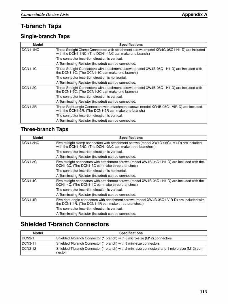
Connectable Device Lists Appendix A
T-branch Taps
Single-branch Taps
Three-branch Taps
Shielded T-branch Connectors
Model Specifications
DCN1-1NC Three Straight Clamp Connectors with attachment screws (model XW4G-05C1-H1-D) are included with the DCN1-1NC. (The DCN1-1NC can make one branch.)
The connector insertion direction is vertical.A Terminating Resistor (included) can be connected.
DCN1-1C Three Straight Connectors with attachment screws (model XW4B-05C1-H1-D) are included with the DCN1-1C. (The DCN1-1C can make one branch.)The connector insertion direction is horizontal.
A Terminating Resistor (included) can be connected.
DCN1-2C Three Straight Connectors with attachment screws (model XW4B-05C1-H1-D) are included with the DCN1-2C. (The DCN1-2C can make one branch.)
The connector insertion direction is vertical.A Terminating Resistor (included) can be connected.
DCN1-2R Three Right-angle Connectors with attachment screws (model XW4B-05C1-VIR-D) are included with the DCN1-2R. (The DCN1-2R can make one branch.)The connector insertion direction is vertical.
A Terminating Resistor (included) can be connected.
Model Specifications
DCN1-3NC Five straight clamp connectors with attachment screws (model XW4G-05C1-H1-D) are included with the DCN1-3NC. (The DCN1-3NC can make three branches.)
The connector insertion direction is vertical.A Terminating Resistor (included) can be connected.
DCN1-3C Five straight connectors with attachment screws (model XW4B-05C1-H1-D) are included with the DCN1-3C. (The DCN1-3C can make three branches.)The connector insertion direction is horizontal.
A Terminating Resistor (included) can be connected.
DCN1-4C Five straight connectors with attachment screws (model XW4B-05C1-H1-D) are included with the DCN1-4C. (The DCN1-4C can make three branches.)
The connector insertion direction is vertical.A Terminating Resistor (included) can be connected.
DCN1-4R Five right-angle connectors with attachment screws (model XW4B-05C1-VIR-D) are included with the DCN1-4R. (The DCN1-4R can make three branches.)The connector insertion direction is vertical.
A Terminating Resistor (included) can be connected.
Model Specifications
DCN2-1 Shielded T-branch Connector (1 branch) with 3 micro-size (M12) connectors
DCN3-11 Shielded T-branch Connector (1 branch) with 3 mini-size connectors
DCN3-12 Shielded T-branch Connector (1 branch) with 2 mini-size connectors and 1 micro-size (M12) con-nector
113

Connectable Device Lists Appendix A
Flat Cable Connectors
Power Supply Tap
Cable Connectors for Sensor Terminals
Cable Connectors for Environment-resistive SlavesThe following cable connectors for Environment-resistive Slaves cannot be used for DeviceNet communica-tions because of differences such as the number of pins that are used.
For DRT1-@D@@C(-1) Slaves
Model Specifications
DCN4-TR4-1 Flat connector socket for flat cable
DCN4-BR4 Flat connector plug for flat cable
DCN4-BR4D Thin Cable-Flat Cable conversion connector.Used to branch to thin cable.
Model Specifications
DCN1-1P The DCN1-1P is used to connect the communications power supply to the network.
Includes two XW4B-05C1-H1-D Straight Connectors with attachment screws, a terminator, and two fuses.A Terminating Resistor (included) can be connected.
Model Specifications
XS8A-0441 Connector marking: XS8-1Applicable cable wire size: 0.3 to 0.5 mm2
XS8A-0442 Connector marking: XS8-2Applicable cable wire size: 0.14 to 0.2 mm2
Connector type Model Specifications
I/O connectors XS2G-D4@@ Shielded, micro-size (M12) male plug connector for custom cable assembly (crimp or solder)
XS2H-D421-@@@ Cable with shielded, micro-size (M12) male plug connector on one end and loose wires on the other
XS2W-D42@-@@@ Cable with shielded, micro-size (M12) connectors on both ends (male plug on one end and female socket on the other)
External power sup-ply connectors
XS2C-D4@@ Shielded, micro-size (M12) female socket connector for custom cable assembly (crimp or solder)
XS2F-D42@-@80-A Cable with shielded, micro-size (M12) female socket connector on one end and loose wires on the other
114

Connectable Device Lists Appendix A
For DRT1-@D@@CL(-1) Slaves
For DRT1-B7AC Slaves
T Joint
Y Joint
Connectors for Environment-resistive Slaves
Connector type Model Specifications
I/O connectors XS2G-D4@@ Shielded, micro-size (M12) male plug connector for custom cable assembly (crimp or solder)
XS2H-D421-@@@-@ Cable with shielded, micro-size (M12) male plug connector on one end and loose wires on the other
XS2W-D42@-@@@-@ Cable with shielded, micro-size (M12) connectors on both ends (male plug on one end and female socket on the other)
External power sup-ply connectors
XS2C-D4@@ Shielded, micro-size (M12) female socket connector for custom cable assembly (crimp or solder)
XS2F-D42@-@80-@ Cable with shielded, micro-size (M12) female socket connector on one end and loose wires on the other
XS2W-D42@-@@@-@ Cable with shielded, micro-size (M12) connectors on both ends (female socket on one end and male plug on the other)
Connector type Model Specifications
I/O connectors XS2G-D4@@ Shielded, micro-size (M12) male plug connector for custom cable assembly (crimp or solder)
XS2H-D42@-@@@-@ Cable with shielded, micro-size (M12) male plug connector on one end and loose wires on the other
XS2W-D42@-@@@-@ Cable with shielded, micro-size (M12) connectors on both ends (male plug on one end and female socket on the other)
External power sup-ply connectors
XS2C-D4@@ Shielded, micro-size (M12) female socket connector for custom cable assembly (crimp or solder)
XS2F-D42@-@@@-@ Cable with shielded, micro-size (M12) female socket connector on one end and loose wires on the other
XS2W-D42@-@@@-@ Cable with shielded, micro-size (M12) connectors on both ends (female socket on one end and male plug on the other)
Model Specifications
XS2R-D427-5 Use the Shielded T-branch Joint to branch a cable for the Environment-resistive Slave’s internal power supply.
Model Specifications
XS2R-D426-@11F With cable Use with 16-input or 16-output Environment-resistive Terminals. (Branches one connector’s signals to two connectors.)XS2R-D426-1 Without cable
Model Specifications
XS2Z-12 Waterproof Cover (Meets IP67 enclosure rating.)
XS2Z-15 Dust cover
115
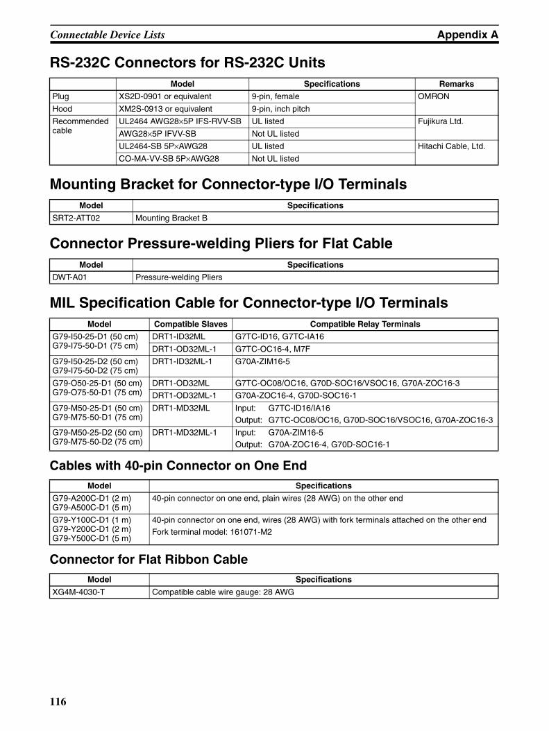
Connectable Device Lists Appendix A
RS-232C Connectors for RS-232C Units
Mounting Bracket for Connector-type I/O Terminals
Connector Pressure-welding Pliers for Flat Cable
MIL Specification Cable for Connector-type I/O Terminals
Cables with 40-pin Connector on One End
Connector for Flat Ribbon Cable
Model Specifications Remarks
Plug XS2D-0901 or equivalent 9-pin, female OMRON
Hood XM2S-0913 or equivalent 9-pin, inch pitch
Recommended cable
UL2464 AWG28×5P IFS-RVV-SB UL listed Fujikura Ltd.
AWG28×5P IFVV-SB Not UL listed
UL2464-SB 5P×AWG28 UL listed Hitachi Cable, Ltd.
CO-MA-VV-SB 5P×AWG28 Not UL listed
Model Specifications
SRT2-ATT02 Mounting Bracket B
Model Specifications
DWT-A01 Pressure-welding Pliers
Model Compatible Slaves Compatible Relay Terminals
G79-I50-25-D1 (50 cm)G79-I75-50-D1 (75 cm)
DRT1-ID32ML G7TC-ID16, G7TC-IA16
DRT1-OD32ML-1 G7TC-OC16-4, M7F
G79-I50-25-D2 (50 cm)G79-I75-50-D2 (75 cm)
DRT1-ID32ML-1 G70A-ZIM16-5
G79-O50-25-D1 (50 cm)G79-O75-50-D1 (75 cm)
DRT1-OD32ML G7TC-OC08/OC16, G70D-SOC16/VSOC16, G70A-ZOC16-3
DRT1-OD32ML-1 G70A-ZOC16-4, G70D-SOC16-1
G79-M50-25-D1 (50 cm)G79-M75-50-D1 (75 cm)
DRT1-MD32ML Input: G7TC-ID16/IA16Output: G7TC-OC08/OC16, G70D-SOC16/VSOC16, G70A-ZOC16-3
G79-M50-25-D2 (50 cm)G79-M75-50-D2 (75 cm)
DRT1-MD32ML-1 Input: G70A-ZIM16-5Output: G70A-ZOC16-4, G70D-SOC16-1
Model Specifications
G79-A200C-D1 (2 m)G79-A500C-D1 (5 m)
40-pin connector on one end, plain wires (28 AWG) on the other end
G79-Y100C-D1 (1 m)G79-Y200C-D1 (2 m)G79-Y500C-D1 (5 m)
40-pin connector on one end, wires (28 AWG) with fork terminals attached on the other endFork terminal model: 161071-M2
Model Specifications
XG4M-4030-T Compatible cable wire gauge: 28 AWG
116

Connectable Device Lists Appendix A
Loose Wire Crimp Connectors
I/O Connecting Cables for MULTIPLE I/O TERMINAL Units
Connectors for MULTIPLE I/O TERMINAL Units
Item Model Specifications
Socket XG5M-4032-N Compatible cable wire gauge: 24 AWG
XG5M-4035-N Compatible cable wire gauge: 28 to 26 AWG
Partial Cover XG5S-2001 Two required per connector.
Hood Cover XG5S-5022 Cannot be used with multi-drop DeviceNet connectors.
Model Specifications
(Provided with I/O Units) Cable length: 40 mm
(Provided with Communications Units) End connector
GCN1-010 Cable length: 0.1 m
GCN1-030 Cable length: 0.3 m
GCN1-040 Cable length: 0.4 m
GCN1-060 Cable length: 0.6 m
GCN1-100 Cable length: 1 m
Model Description Remarks
14-60-0032 MOLEX connectors Pressure weld con-nection
Housing For 24 AWG
50-57-9403 Crimp connection Housing
16-02-0069 Reeled pins For 24 to 30 AWG
16-02-0086 For 22 to 24 AWG
16-02-0096 Loose pins For 24 to 30 AWG
16-02-0102 For 22 to 24 AWG
11-01-0209 Crimping Tool For 24 to 30 AWG
117

Connectable Device Lists Appendix A
Connector Cables for MULTIPLE I/O TERMINAL Units
Recommended Power Supplies for MULTIPLE I/O TERMINAL Units
Model Unit connected
G79-@@@C Connects a GT1-ID16ML to an I/O Block (G7TC-I@16).
Connects a GT1-OD16ML to an I/O Block (G7TC-OC16, G7OD-SOC16, G7OD-FOM16, G7OA-ZOC16-3, or M7F).
Connects a GT1-OD16ML-1 to an I/O Block (G7TC-OC16-1, G7OD-SOC16-1, G7OD-FOM16-1, G7OA-ZOC16-4, or M7F).
G79-I@C-@ Connects a GT1-ID32ML or to an I/O Block (G7TC-I@16).
G79-0@C-@ Connects a GT1-OD32ML to an I/O Block (G7TC-OC16, G7TC-OC08, G70D-SOC16, G7OD-FOM16, G70A-ZOC16-3, or M7F).
Connects a GT1-OD32ML-1 to an I/O Block (G7TC-OC16-1, G70D-SOC16-1, G7OD-FOM16-1, or G70A-ZOC16-4).
XW2Z-@@@A Connects a GT1-ID16ML(-1) or GT1-OD16ML(-1) to a Connector-Terminal Block Conversion Unit (XW2B-20G4 or XW2B-20G5)
XW2X-@@@B Connects a GT1-ID32ML(-1) or GT1-OD32ML(-1) to a Connector-Terminal Block Conversion Unit (XW2B-40G4 or XW2B-40G5)
Model Specifications
S82K-05024 100 V AC, 50 W
S82K-10024 100 V AC, 100 W
S82J-5524 100 V AC, 50 W
S82J-5024 100 V AC, 100 W
118

Appendix BDimensions of Connectable Devices
Connectors for Node Connections
XW4B-05C1-H1-D Straight Connector with Attachment Screws
MSTB2.5/5-ST-5.08AU Straight Connector without Attachment Screws
XW4B-05C1-VIR-D Right-angle Connector with Attachment Screws
25.4
20.3
2
5.08
15.0
18.2
35.0
5.08
3.73
Power supply connection
Black
BlueShieldWhite
Red
All dimensions are in mm.
25.4
20.3
2
5.08
15.0
18.2
Black
BlueShieldWhite
Red
All dimensions are in mm.
Power supply connection
26.4
26
35.5
3.73
20.3
2
5.08
5.08
12.6
Black
BlueShieldWhite
Red
All dimensions are in mm.
Power supply connection
119

Dimensions of Connectable Devices Appendix B
XW4G-05C1-H1-D
XW4B-05C4-TF-D Straight Multi-drop Connector with Attachment Screws
XW4B-05C4-T-D Straight Multi-drop Connector without Attachment Screws
15
5.08
20.3
2
Black
Blue
White
Red
Power supply connection
All dimensions are in mm.
20.3
2
14.4
5
8.3
14.4
528.9
35.3
27.3
25.4
5.08
5.08
3.73
7.8
21.5
Black
BlueShieldWhite
Red
Black
BlueShieldWhite
Red
All dimensions are in mm.
Power supply connection
25.4
20.3
2
5.08
14.4
5
21.5
27.4
14.4
528.9
Black
BlueShieldWhite
Red
Black
BlueShieldWhite
Red
All dimensions are in mm.
Power supply connection
120

Dimensions of Connectable Devices Appendix B
XW4G-05C4-TF-D
DCN4-SF4D Flat Cable Connector
(7.7)16.7
25
225.8(6.9)
5.08
20.3
226 35
.4
Power supply connection
Black
Blue
White
Red
All dimensions are in mm.
11.1
27
1.45
18.1
4
30.20
3612
.64
38.55All dimensions are in mm.
121

Dimensions of Connectable Devices Appendix B
T-branch Taps
DCN1-1NC T-branch Tap (Single Branch)
74.5
67.5
20 20
1445
46
30.920.5
74.5±0.1
14.15±0.1
Mounting holes or taps Two, 3.5±0.1-dia. or M3
All dimensions are in mm.
122

Dimensions of Connectable Devices Appendix B
DCN1-1C T-branch Tap (Single Branch)
DCN1-2C and DCN1-2R T-branch Taps (Single Branches)
97±0.3
90
14±0
.3
15.5
DCN1-1T-PORT TAP
45
97
7
15.5
21
31
Mounting holes or taps
Two, 3.5 dia. or M3
All dimensions are in mm.
97±0.3
90
14±0
.3
15.5
DCN1-2T-PORT TAP
45
97
7
15.5
21
31
Two, 3.5 dia. or M3
Mounting holes or taps
All dimensions are in mm.
123

Dimensions of Connectable Devices Appendix B
DCN1-3NC T-branch Tap (Three Branches)
DCN1-3C T-branch Tap (Three Branches)
97
90
17 17 17 172.3
45 14
46
30.920.5
97±0.1
14±0.1
Two, 3.5±0.1-dia. or M3Mounting holes or taps
All dimensions are in mm.
142±0.3
135
14±0
.3
15.5
21
31
DCN1-3T-PORT TAP
45
142
7
15.5
Two, 3.5 dia. or M3
Mounting holes or taps
All dimensions are in mm.
124
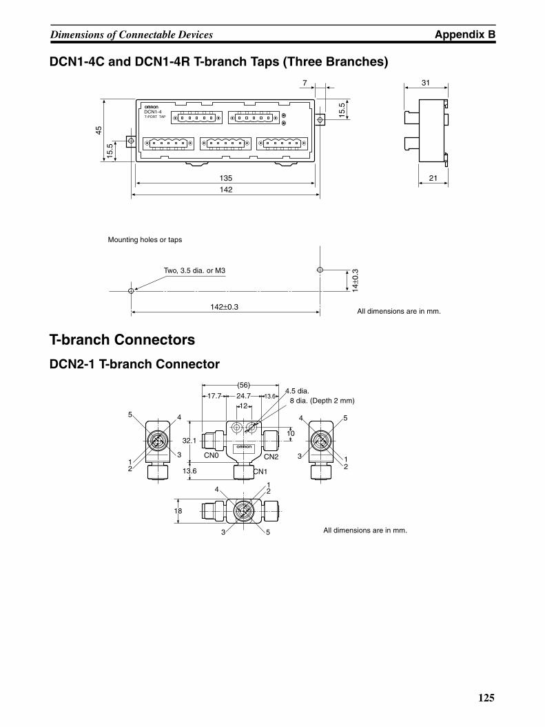
Dimensions of Connectable Devices Appendix B
DCN1-4C and DCN1-4R T-branch Taps (Three Branches)
T-branch Connectors
DCN2-1 T-branch Connector
142±0.3
135
14±0
.3
15.5
21
31
DCN1-4T-PORT TAP
45
142
7
15.5
Two, 3.5 dia. or M3
Mounting holes or taps
All dimensions are in mm.
(56)
24.717.7
32.1
13.6
13.6
12
10
CN0
CN1
CN2
21
5
2
21
54
3
14
3 5
4
3
4.5 dia.
18
8 dia. (Depth 2 mm)
All dimensions are in mm.
125
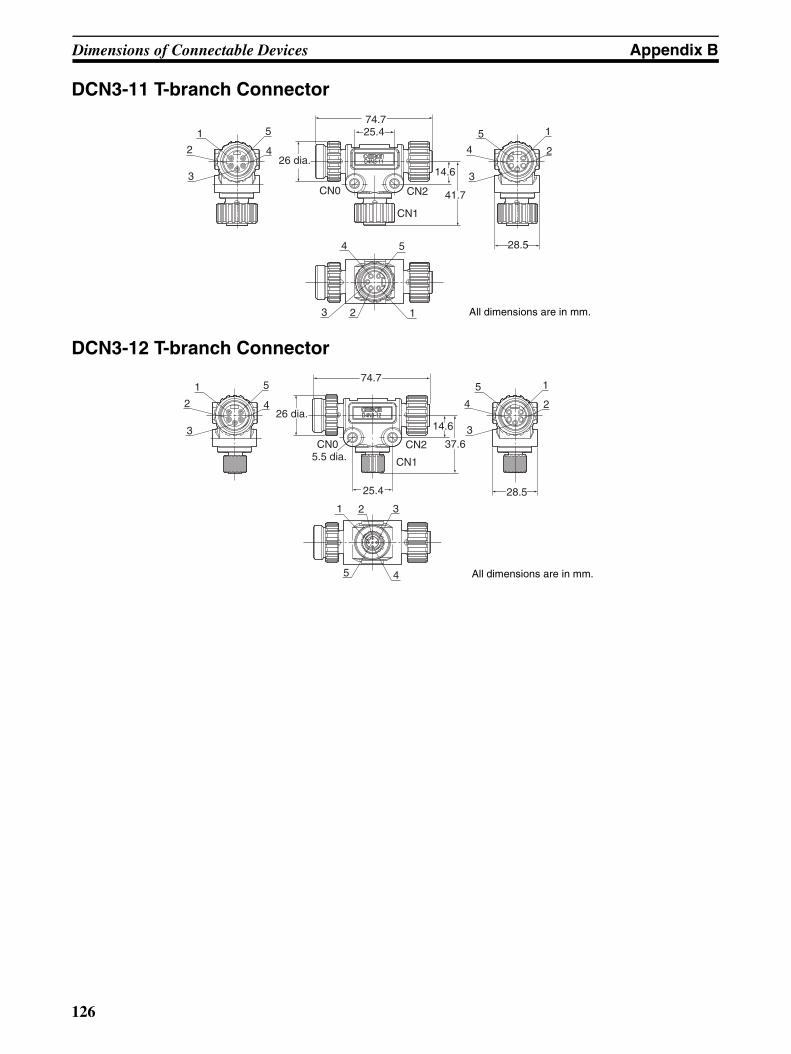
Dimensions of Connectable Devices Appendix B
DCN3-11 T-branch Connector
DCN3-12 T-branch Connector
D4N3-11
1
2
3
5
4
CN0 CN2
CN1
26 dia.
74.7
14.6
41.7
28.5
5
4
3
2
1
4 5
123
25.4
All dimensions are in mm.
D4N3-12
1
2
3
5
426 dia.
74.7
25.4
CN05.5 dia.
CN2
CN1
14.6
37.6
1 32
5 4
28.5
3
4
5 1
2
All dimensions are in mm.
126
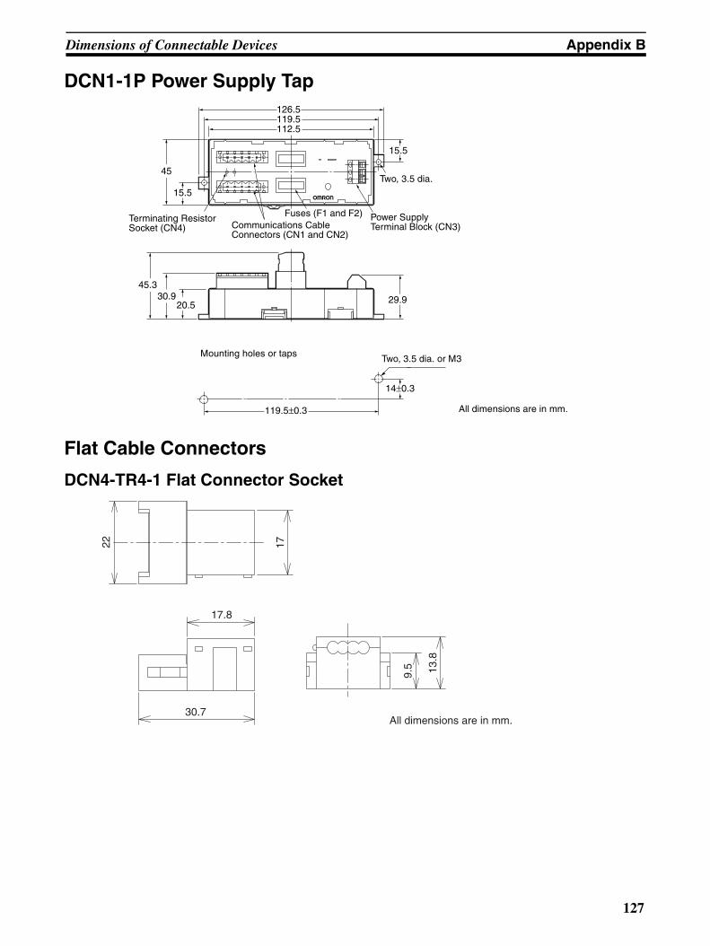
Dimensions of Connectable Devices Appendix B
DCN1-1P Power Supply Tap
Flat Cable Connectors
DCN4-TR4-1 Flat Connector Socket
126.5119.5
15.5
14±0.3
29.9
112.5
45.330.9
20.5
15.5
45
119.5±0.3
Two, 3.5 dia.
Two, 3.5 dia. or M3
Terminating Resistor Socket (CN4)
Power Supply Terminal Block (CN3)Communications Cable
Connectors (CN1 and CN2)
Fuses (F1 and F2)
Mounting holes or taps
All dimensions are in mm.
22 17
17.8
All dimensions are in mm.30.7
9.5 13
.8
127

Dimensions of Connectable Devices Appendix B
DCN4-BR4 Flat Connector Plug
DCN4-BR4D Thin Cable-Flat Cable Conversion Connector
20
8.3
21.3
(23)
9.5
9.2
20
8.3
21.3
(23)
9.5
9.2
128

Dimensions of Connectable Devices Appendix B
Terminating Resistors
DRS1-T Terminal-block Terminating Resistor
DRS2-1 and DRS2-2 Shielded Micro-size (M12) Terminators
Note The terminating resistance (121 Ω) is connected across pins 4 and 5.
DRS3-1 Shielded Mini-size Terminator
Note The terminating resistance (121 Ω) is connected across pins 4 and 5.
30±0.2
40
20
20
DRS1-T
20
Two, 4.2 dia. or M4
Mounting holes or taps
All dimensions are in mm.
12345
12
4
M12
3
5
8.5 dia.14.9 dia. 13.6 dia.
44.7
DRAINV+V−
CAN HCAN L
: NC: NC: NC:: 121 Ω
Wiring
Pin Name
All dimensions are in mm.
Pin12345
DRAINV+V−
CAN HCAN L
: NC: NC: NC:: 121 Ω
26 dia.
1662.5
4
51
2
3
Name
Wiring
All dimensions are in mm.
129

Dimensions of Connectable Devices Appendix B
DCN4-TP4D Flat Cable Power Supply Terminal Block with Terminating Resistance
29
20.903
4.55 6
1716
.20
33.60
13.50
All dimensions are in mm.
130

Appendix CCurrent Consumption of DeviceNet Devices
Master UnitsModel Internal current consumption Communications current consumption
CS1W-DRM21(-V1) 290 mA max. 30 mA max.
CJ1W-DRM21 290 mA max. 18 mA max.
CVM1-DRM21-V1 250 mA max. 45 mA max.
C200HW-DRM21-V1 250 mA max. 45 mA max.
3G8F7-DRM21 290 mA max. 30 mA max.
131

Current Consumption of DeviceNet Devices Appendix C
Slave Units
DRT2-series General-purpose SlavesModel Communications current consumption
DRT2-ID16 60 mA max.
DRT2-ID16-1 60 mA max.
DRT2-OD16 60 mA max.
DRT2-OD16-1 60 mA max.
DRT2-ROS16 395 mA max.
XWT-ID08 (See note.) 5 mA max.
XWT-ID08-1 (See note.) 5 mA max.
XWT-ID16 (See note.) 10 mA max.
XWT-ID16-1 (See note.) 10 mA max.
XWT-OD08 (See note.) 4.5 mA max.
XWT-OD08-1 (See note.) 4.5 mA max.
XWT-OD16 (See note.) 10 mA max.
XWT-OD16-1 (See note.) 10 mA max.
DRT2-ID16TA 80 mA max.
DRT2-ID16TA-1 80 mA max.
DRT2-OD16TA 80 mA max.
DRT2-OD16TA-1 80 mA max.
DRT2-MD16TA 80 mA max.
DRT2-MD16TA-1 80 mA max.
DRT2-ID16S 230 mA max.
DRT2-ID16S-1 230 mA max.
DRT2-MD16S 135 mA max.
DRT2-MD16S-1 135 mA max.
DRT2-ID32ML 100 mA max.
DRT2-ID32ML-1 100 mA max.
DRT2-OD32ML 120 mA max.
DRT2-OD32ML-1 120 mA max.
DRT2-MD32ML 110 mA max.
DRT2-MD32ML-1 110 mA max.
DRT2-ID32B 100 mA max.
DRT2-ID32B-1 100 mA max.
DRT2-OD32B 120 mA max.
DRT2-OD32B-1 120 mA max.
DRT2-MD32B 110 mA max.
DRT2-MD32B-1 110 mA max.
DRT2-ID32BV 100 mA max.
DRT2-ID32BV-1 100 mA max.
DRT2-OD32BV 120 mA max.
DRT2-OD32BV-1 120 mA max.
DRT2-MD32BV 110 mA max.
DRT2-MD32BV-1 110 mA max.
DRT2-ID16SL 28 mA max.
DRT2-ID16SL-1 27 mA max.
DRT2-OD16SL 32 mA max.
DRT2-OD16SL-1 31 mA max.
132
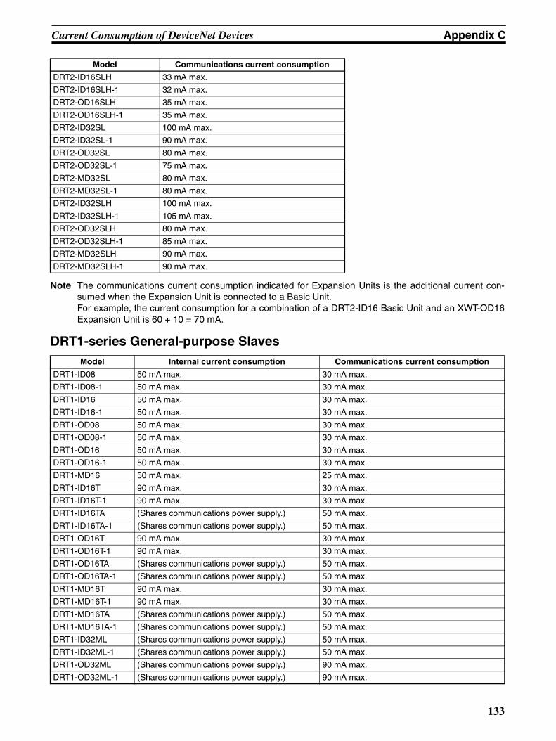
Current Consumption of DeviceNet Devices Appendix C
Note The communications current consumption indicated for Expansion Units is the additional current con-sumed when the Expansion Unit is connected to a Basic Unit. For example, the current consumption for a combination of a DRT2-ID16 Basic Unit and an XWT-OD16Expansion Unit is 60 + 10 = 70 mA.
DRT1-series General-purpose Slaves
DRT2-ID16SLH 33 mA max.
DRT2-ID16SLH-1 32 mA max.
DRT2-OD16SLH 35 mA max.
DRT2-OD16SLH-1 35 mA max.
DRT2-ID32SL 100 mA max.
DRT2-ID32SL-1 90 mA max.
DRT2-OD32SL 80 mA max.
DRT2-OD32SL-1 75 mA max.
DRT2-MD32SL 80 mA max.
DRT2-MD32SL-1 80 mA max.
DRT2-ID32SLH 100 mA max.
DRT2-ID32SLH-1 105 mA max.
DRT2-OD32SLH 80 mA max.
DRT2-OD32SLH-1 85 mA max.
DRT2-MD32SLH 90 mA max.
DRT2-MD32SLH-1 90 mA max.
Model Internal current consumption Communications current consumption
DRT1-ID08 50 mA max. 30 mA max.
DRT1-ID08-1 50 mA max. 30 mA max.
DRT1-ID16 50 mA max. 30 mA max.
DRT1-ID16-1 50 mA max. 30 mA max.
DRT1-OD08 50 mA max. 30 mA max.
DRT1-OD08-1 50 mA max. 30 mA max.
DRT1-OD16 50 mA max. 30 mA max.
DRT1-OD16-1 50 mA max. 30 mA max.
DRT1-MD16 50 mA max. 25 mA max.
DRT1-ID16T 90 mA max. 30 mA max.
DRT1-ID16T-1 90 mA max. 30 mA max.
DRT1-ID16TA (Shares communications power supply.) 50 mA max.
DRT1-ID16TA-1 (Shares communications power supply.) 50 mA max.
DRT1-OD16T 90 mA max. 30 mA max.
DRT1-OD16T-1 90 mA max. 30 mA max.
DRT1-OD16TA (Shares communications power supply.) 50 mA max.
DRT1-OD16TA-1 (Shares communications power supply.) 50 mA max.
DRT1-MD16T 90 mA max. 30 mA max.
DRT1-MD16T-1 90 mA max. 30 mA max.
DRT1-MD16TA (Shares communications power supply.) 50 mA max.
DRT1-MD16TA-1 (Shares communications power supply.) 50 mA max.
DRT1-ID32ML (Shares communications power supply.) 50 mA max.
DRT1-ID32ML-1 (Shares communications power supply.) 50 mA max.
DRT1-OD32ML (Shares communications power supply.) 90 mA max.
DRT1-OD32ML-1 (Shares communications power supply.) 90 mA max.
Model Communications current consumption
133

Current Consumption of DeviceNet Devices Appendix C
DRT2-series Environment-resistive Slaves
DRT1-series Environment-resistive Slaves
DRT1-MD32ML (Shares communications power supply.) 70 mA max.
DRT1-MD32ML-1 (Shares communications power supply.) 70 mA max.
DRT1-ID16X 70 mA max. 30 mA max.
DRT1-ID16X-1 70 mA max. 30 mA max.
DRT1-OD16X 70 mA max. 30 mA max.
DRT1-OD16X-1 70 mA max. 30 mA max.
DRT1-HD16S 60 mA max. 40 mA max.
DRT1-ND16S 60 mA max. 40 mA max.
CQM1-DRT21 80 mA max. (Supplied from the 5 V DC base.) 40 mA max.
CPM1A-DRT21 50 mA max. 30 mA max.
Model Communications current consumption
DRT2-ID08C 115 mA max.
DRT2-ID08C-1 115 mA max.
DRT2-HD16C 190 mA max.
DRT2-HD16C-1 190 mA max.
DRT2-OD08C 60 mA max.
DRT2-OD08C-1 60 mA max.
DRT2-ID04CL 50 mA max.
DRT2-ID04CL-1 50 mA max.
DRT2-ID08CL 50 mA max.
DRT2-ID08CL-1 50 mA max.
DRT2-HD16CL 55 mA max.
DRT2-HD16CL-1 55 mA max.
DRT2-OD04CL 45 mA max.
DRT2-OD04CL-1 45 mA max.
DRT2-OD08CL 50 mA max.
DRT2-OD08CL-1 50 mA max.
DRT2-WD16CL 55 mA max.
DRT2-WD16CL-1 55 mA max.
DRT2-MD16CL 55 mA max.
DRT2-MD16CL-1 55 mA max.
Model Internal current consumption Communications current consumption
DRT1-ID04CL (Shares communications power supply.) 25 mA max.
DRT1-ID04CL-1 (Shares communications power supply.) 25 mA max.
DRT1-ID08CL (Shares communications power supply.) 30 mA max.
DRT1-ID08CL-1 (Shares communications power supply.) 30 mA max.
DRT1-ID08C 50 mA max. 30 mA max.
DRT1-HD16C 50 mA max. 30 mA max.
DRT1-HD16C-1 50 mA max. 30 mA max.
DRT1-OD04CL (Shares communications power supply.) 35 mA max.
DRT1-OD04CL-1 (Shares communications power supply.) 35 mA max.
DRT1-OD08CL (Shares communications power supply.) 40 mA max.
DRT1-OD08CL-1 (Shares communications power supply.) 40 mA max.
DRT1-OD08C 50 mA max. 30 mA max.
Model Internal current consumption Communications current consumption
134
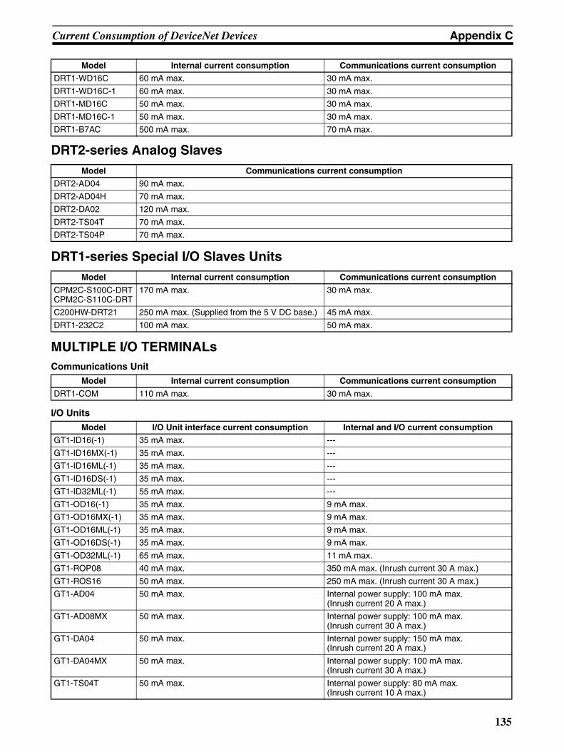
Current Consumption of DeviceNet Devices Appendix C
DRT2-series Analog Slaves
DRT1-series Special I/O Slaves Units
MULTIPLE I/O TERMINALsCommunications Unit
I/O Units
DRT1-WD16C 60 mA max. 30 mA max.
DRT1-WD16C-1 60 mA max. 30 mA max.
DRT1-MD16C 50 mA max. 30 mA max.
DRT1-MD16C-1 50 mA max. 30 mA max.
DRT1-B7AC 500 mA max. 70 mA max.
Model Communications current consumption
DRT2-AD04 90 mA max.
DRT2-AD04H 70 mA max.
DRT2-DA02 120 mA max.
DRT2-TS04T 70 mA max.
DRT2-TS04P 70 mA max.
Model Internal current consumption Communications current consumption
CPM2C-S100C-DRTCPM2C-S110C-DRT
170 mA max. 30 mA max.
C200HW-DRT21 250 mA max. (Supplied from the 5 V DC base.) 45 mA max.
DRT1-232C2 100 mA max. 50 mA max.
Model Internal current consumption Communications current consumption
DRT1-COM 110 mA max. 30 mA max.
Model I/O Unit interface current consumption Internal and I/O current consumption
GT1-ID16(-1) 35 mA max. ---
GT1-ID16MX(-1) 35 mA max. ---
GT1-ID16ML(-1) 35 mA max. ---
GT1-ID16DS(-1) 35 mA max. ---
GT1-ID32ML(-1) 55 mA max. ---
GT1-OD16(-1) 35 mA max. 9 mA max.
GT1-OD16MX(-1) 35 mA max. 9 mA max.
GT1-OD16ML(-1) 35 mA max. 9 mA max.
GT1-OD16DS(-1) 35 mA max. 9 mA max.
GT1-OD32ML(-1) 65 mA max. 11 mA max.
GT1-ROP08 40 mA max. 350 mA max. (Inrush current 30 A max.)
GT1-ROS16 50 mA max. 250 mA max. (Inrush current 30 A max.)
GT1-AD04 50 mA max. Internal power supply: 100 mA max.(Inrush current 20 A max.)
GT1-AD08MX 50 mA max. Internal power supply: 100 mA max.(Inrush current 30 A max.)
GT1-DA04 50 mA max. Internal power supply: 150 mA max.(Inrush current 20 A max.)
GT1-DA04MX 50 mA max. Internal power supply: 100 mA max.(Inrush current 30 A max.)
GT1-TS04T 50 mA max. Internal power supply: 80 mA max.(Inrush current 10 A max.)
Model Internal current consumption Communications current consumption
135

Current Consumption of DeviceNet Devices Appendix C
GT1-TS04P 50 mA max. Internal power supply: 80 mA max.(Inrush current 10 A max.)
GT1-CT01 90 mA max. 9 mA max.
Model I/O Unit interface current consumption Internal and I/O current consumption
136

Index
Aadapters
remote, 8assembly
precautions, xxi
Bbranch lines
current capacity, 88
reducing length, 35
Ccables
combining thick and thin, 37
communications cables, xxii, 43
connecting, 46, 62
distance, 45
specifications, 46
current capacity, 27, 34, 37, 88
I/O Unit Connecting Cable, 16
limitations, 37
models, 32, 43, 116, 117
precautions, xxii
proper usage, 37
selecting, 37
shielded, 76
special applications, 33
thin cable applications, 38
trunk/branch lines, 23, 26, 27, 33
types, 33, 34, 37
wiring, 54
circuits
emergency stop, xviii
external, xviii
communications
cables
connecting, 62
distance, 45
models, 110
specifications, 46
message communications, 3, 6power supply, 25, 31, 41
details, 87
problems, 84
specifications, 61
wiring, 76
remote I/O communications, 3
specifications, 17
compatible devices, 4Configurator, 3, 17
models, 103
connection methods
branching patterns, 28, 30
communications cables, 46, 62
multi-drop, 24
with multi-drop connector, 65
with standard connector, 65
T-branch, 24, 69
Terminating Resistors, 40, 60, 78
connectors
for node connections, 48
insertion direction, 54
models, 48, 49, 51, 111, 114, 117
RS-232C, 116
multi-drop, 51
wiring, 52, 65
precautions, xxi
shielded, 49, 68
standard, 48, 65
wiring, 62
T-branch, 57
wiring, 52, 62
crimp terminals
models, 112
DDeviceNet Configurator, 3, 17
models, 103
DIP switches
precautions, xxi
Eemergency stop circuits, xviii
Ffeatures, DeviceNet, 2functions, 4
DeviceNet Configurator, 17
message communications, 6Remote I/O Master, 4Remote I/O Slave, 5
137

Index
Ggrounding, xxi, 25, 32, 42, 80
II/O Link Units
C200H I/O Link Unit, 10
CQM 1 I/O Link Unit, 8I/O Terminals
environment-resistant, 9water-resistant, 9
I/O Units
connecting cable, 16
MMaster Units
current consumption, 131
determining location, 39
DeviceNet functions, 4models, 4, 103
models
Boards, 17
cables, 32, 43, 110, 116, 117
Cards, 17
Configurator, 17, 103
connectors, 48, 49, 51, 111, 114, 117
RS-232C, 116
crimp terminals, 112
Master Units, 4, 103
Mounting Brackets, 116
MULTIPLE I/O TERMINAL Units, 15, 109
power supply, 118
Power Supply Tap, 114
Slaves, 7, 9, 10, 104
T-branch Connectors, 58, 113
T-branch Taps, 53
Terminating Resistors, 60
Three-branch Taps, 113
Mounting Brackets
models, 116
MULTIPLE I/O TERMINAL Units
current consumption, 135
models, 15, 109
Nnetwork
configuration, 18, 21, 22, 32
maximum length, 34
nodes, 23, 24, 33, 43
noise, 82, 84
start-up procedure, 18
wiring, 18, 21
nodes
allocating node numbers, 43
connecting to, 69
connectors for, 48
noise
malfunctions due to, 84
minimizing, 82
Ppacking, xxii
power supply
communications, 25, 31, 41, 97
details, 87
problems, 84
specifications, 61
wiring, 76
determining requirements, 89
internal circuit, 41, 97
layout patterns, 90
location, 90
models, 118
multiple power supplies, 101
precautions, xxi
voltage drop, 97
Power Supply Tap, 59, 88
configuration, 101
internal circuits, 101
models, 114
precautions
application, xxi
operating environment, xx
safety, xviii
profiles, 3
Rrotary switches
precautions, xxi
RS-232C Units, 10
138

Index
Ssafety precautions, xviii
scan list, xxii, 19
self-diagnosis function, xviii
short-circuits
precautions, xxi
slaves
connected in Network, 23
current consumption, 132
models, 7, 9, 104
special, 10
types of, 7Special I/O Units, 16
specifications
communications, 17
communications cables, 46
communications power supply, 61
TT-branch Connectors, 88
models, 58, 113
T-branch Taps, 40, 52, 88
components, 55, 57
connecting to, 69
models, 53
terminals
B7AC Interface Terminal, 9precautions, xxii
remote I/O, 7sensor, 8
Terminating Connectors
connecting, 60
Terminating Resistors, 24, 32, 33
connecting, 40, 78
models, 60
Three-branch Taps
models, 113
trunk lines
selecting, 36
Wwiring
cables, 54
communications power supply, 76
connectors
multi-drop, 52
shielded, 68
standard, 62
crimp terminals, 41
DeviceNet Network, 18, 21
precautions, xxi
139

Index
140

Revision History
A manual revision code appears as a suffix to the catalog number on the front cover of the manual.
The following table outlines the changes made to the manual during each revision. Page numbers refer tothe previous version.
Revision code Date Revised content
1 August 1996 Original production
2 June 1997 Complete revision to include V1 Master Units.
3 December 1997 The manual was revised to include new informa-tion on network configuration and wiring, and Temperature Input Terminals.Section 3: Added to include information on net-work configuration and specifications.Page 72: Changes to table.Pages 72 to 84: Additions made to include DRT1-AD04H.Pages 91 to 97: Information added on Temper-ature Input Terminals.
Section 6: Added to include information on the communications power supply.Section 7: Extensively revised to include infor-mation on wiring the network.Page 267: Information changed in table.Appendix F: Added to provide information on connectable devices and current consumption.
4 April 1998 The manual was revised to correct errors and include new information on multiple I/O termi-nals.Page 6: Table added to include information on MULTIPLE I/O TERMINAL. Page 34: Information on MULTIPLE I/O TERMI-NAL added.Pages 46, 51, 56, 60, 65, 72, 84, 91: Specifica-tions corrected.Pages 47, 53, 58, 62, 67, 68, 76: “Insulated” corrected to “isolated.”Pages 50, 56, 60, 64, 71, 84, 91, 98: Note on opening the cover removed.Page 92: Note on converted data removed.
Section 5-3: Added to include information on MULTIPLE I/O TERMINAL.Section 7-12: Added to include information on installation and connection of MULTIPLE I/O TERMINALPages 350 to 352: Information on MULTIPLE I/O TERMINAL response times and communica-tions cycle times added.Pages 363 to 368: Error processing information for MULTIPLE I/O TERMINAL added.Page 407: Communications Unit device profile added.Page 418: Connectable device information updated to include MULTIPLE I/O TERMINAL.
5 May 2000 Changes were made throughout the manual to correct errors and include new information on CS1-series PLCs, Basic and Special I/O Units, MULTIPLE I/O TERMINAL Units, and Environ-ment-resistant Terminals. “CompoBus/D” was changed to “DeviceNet” and “CV-series” was amended to “CVM1 and CV-series” throughout the manual.Pages 2, 7, 8, 22, 32, 37, 40, 185, 193, 208, 211, 212, 216, 220, 224, 227, 234-236, 239-242, 252-254, 313, 325, 328-335, 340, 345, 355, 356, 365, 371, 377-379: Information on CS1-series PLCs added.Pages 3-6: Major changes to model informa-tion.Pages 7, 15, 19, 341-347: Notes changed/added.Page 13: Correction made to information on communications cycle time.Pages 21, 27: Information on reference sources added/changed.Pages 23, 228: Information on communications setup added.Sections 5-1 to 5-3: Removed.Sections 5-4-8 to 5-4-12: Removed.Page 181: Information on dual power supply changed.
Page 184: Torque data changed. Information on mounting added.Section 7-2-2: Removed.Pages 187, 219, 226: Changes to graphics.Pages 190-192: Torque data changed.Sections 7-11, 7-12: Removed.Pages 204, 218, 384, 400, 401: Changes made to tables.Pages 234, 246, 253, 259, 260: Information on explicit messages added.Page 326: Information on error log data added.Pages 338-339: Changes made to information on communications cycle time. Information for networks with more than one Master moved to page 347.Pages 346-349: Equations changed/added.Section 14-1-3: Removed.Page 382: Information on troubleshooting for Analog I/O Units, Temperature Input Terminals, the C200H I/O Link Unit, and the RS-232C Unit added.Page 399: Change to introduction. Information on connection to other company’s Masters removed.Pages 402-408: Removed.Appendix E: Removed.
Appendix F: New model information added.
6 October 2000 Reprinted due to error.
07 August 2002 Completely redone to separate information on Masters into a separate manual, to add round con-nectors and other connectors, and to add T-branch Taps and other new products.
Cat. No. W267-E1-11
Revision code
141
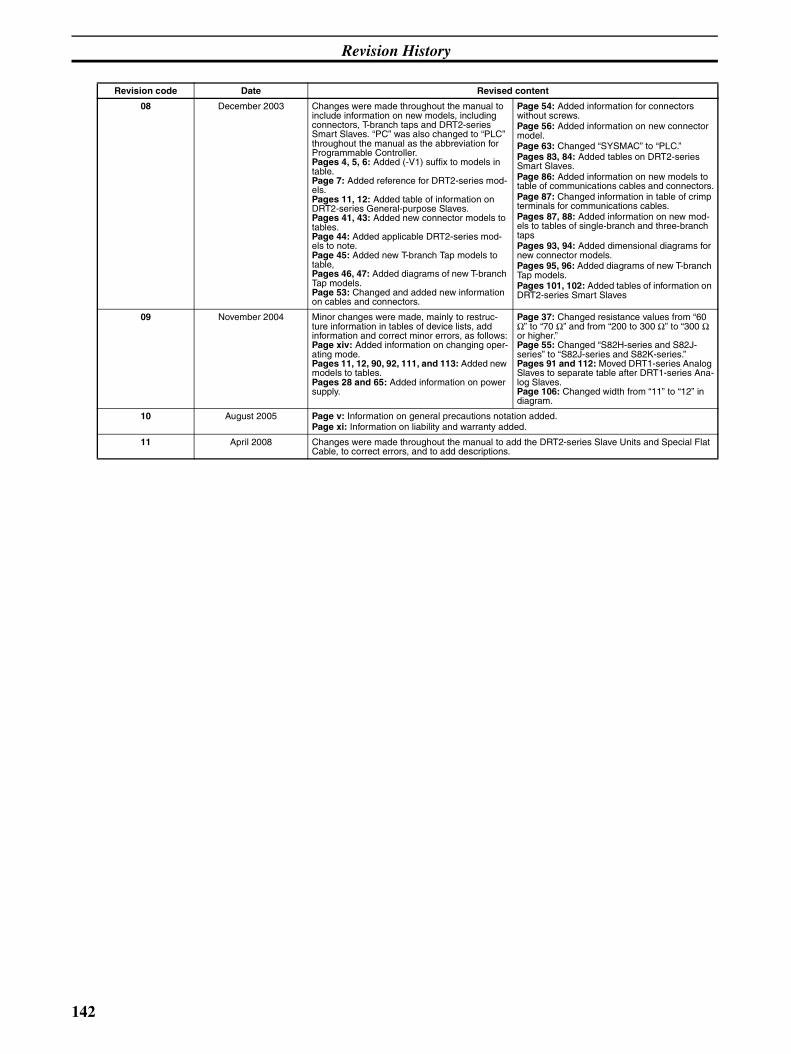
Revision History
08 December 2003 Changes were made throughout the manual to include information on new models, including connectors, T-branch taps and DRT2-series Smart Slaves. “PC” was also changed to “PLC” throughout the manual as the abbreviation for Programmable Controller.Pages 4, 5, 6: Added (-V1) suffix to models in table.Page 7: Added reference for DRT2-series mod-els.Pages 11, 12: Added table of information on DRT2-series General-purpose Slaves.Pages 41, 43: Added new connector models to tables.Page 44: Added applicable DRT2-series mod-els to note.Page 45: Added new T-branch Tap models to table,Pages 46, 47: Added diagrams of new T-branch Tap models.Page 53: Changed and added new information on cables and connectors.
Page 54: Added information for connectors without screws.Page 56: Added information on new connector model.Page 63: Changed “SYSMAC” to “PLC.”Pages 83, 84: Added tables on DRT2-series Smart Slaves.Page 86: Added information on new models to table of communications cables and connectors.Page 87: Changed information in table of crimp terminals for communications cables.Pages 87, 88: Added information on new mod-els to tables of single-branch and three-branch taps Pages 93, 94: Added dimensional diagrams for new connector models.Pages 95, 96: Added diagrams of new T-branch Tap models.Pages 101, 102: Added tables of information on DRT2-series Smart Slaves
09 November 2004 Minor changes were made, mainly to restruc-ture information in tables of device lists, add information and correct minor errors, as follows:Page xiv: Added information on changing oper-ating mode.Pages 11, 12, 90, 92, 111, and 113: Added new models to tables.Pages 28 and 65: Added information on power supply.
Page 37: Changed resistance values from “60 Ω” to “70 Ω” and from “200 to 300 Ω” to “300 Ω or higher.”Page 55: Changed “S82H-series and S82J-series” to “S82J-series and S82K-series.”Pages 91 and 112: Moved DRT1-series Analog Slaves to separate table after DRT1-series Ana-log Slaves.Page 106: Changed width from “11” to “12” in diagram.
10 August 2005 Page v: Information on general precautions notation added.Page xi: Information on liability and warranty added.
11 April 2008 Changes were made throughout the manual to add the DRT2-series Slave Units and Special Flat Cable, to correct errors, and to add descriptions.
Revision code Date Revised content
142