DeviceNet Buscoupler - CD Automation · DeviceNet Buscoupler Interface description DeviceNet...
24
1 CD Automation srl DeviceNet Buscoupler Interface description DeviceNet Interface 9499 040 70011 01/2005
Transcript of DeviceNet Buscoupler - CD Automation · DeviceNet Buscoupler Interface description DeviceNet...
1
CD Automation srl DeviceNet Buscoupler
Interface description DeviceNet Interface 9499 040 70011
01/2005

All rights reserved. No part of this document may be reproduced or published in any form or by anymeans without prior written permission from the copyright owner.
Content
1. General . . . . . . . . . . . . . . . . . . . . . . . . . . . . . . . . . . . . . . . . . . . 4
2. Hints for operation . . . . . . . . . . . . . . . . . . . . . . . . . . . . . . . . . . . . . . . 62.1. Connecting the interface, signification of indicator LEDs on the bus coupler . . . . 62.2. Forcing . . . . . . . . . . . . . . . . . . . . . . . . . . . . . . . . . . . . . . . . . 72.3. Fail-safe. . . . . . . . . . . . . . . . . . . . . . . . . . . . . . . . . . . . . . . . . 7
3. Communication via DeviceNet . . . . . . . . . . . . . . . . . . . . . . . . . . . . . . . . 83.1. Basic settings for DeviceNet communication in the “BlueControl” engineering tool. 83.2. Definition of transmitted data in the “BlueControl” engineering tool . . . . . . . . . 93.3. Structure of the data cache in vario . . . . . . . . . . . . . . . . . . . . . . . . 113.4. Example . . . . . . . . . . . . . . . . . . . . . . . . . . . . . . . . . . . . . . . . 123.5. Communication with the PLC at the example of Rockwell with RSNetWorx . . . . 13
3.5.1 EDS installation and network configuration with RSNetWorx . . . . . . . 133.5.2 Example: DeviceNet communication procedure (PLC <--> vario) . . . . 19
3.6. Parameter access to vario data in RSNetWorx. . . . . . . . . . . . . . . . . . 21
4. vario DeviceNet “Object directory” . . . . . . . . . . . . . . . . . . . . . . . . . . 22
. 1. GeneralModular controller system vario permits connection of various fieldbus interfaces. For this purpose, the relevant buscoupler is used as a head station for a controller system.Via one of these bus couplers, the DeviceNet protocol is supported by means of a front-panel interface (9-pole Sub-Dconnector). Hereby, transmission of all process, parameter and configuration data is possible.This communication interface permits communication with supervisory systems, visualization tools, etc.Another standard interface is provided on the vario controller modules. This full RS232 interface is used forconnection of the ‘BlueControl’ tool, which runs on a PC.
CAN PhysicalLayer
There are various standards related to the CAN Physical Layer. The most important standard for general applications isthe “CAN High-Speed Standard ISO 11898-2". The recommendations given below are based primarily on this standardand are valid independent of the used CAN protocol (CANopen / DeviceNet).
ISO 118982nodes
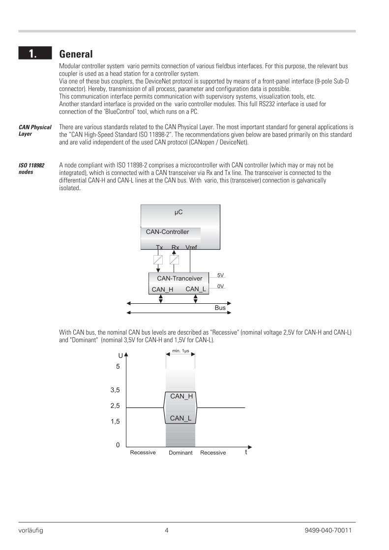
A node compliant with ISO 11898-2 comprises a microcontroller with CAN controller (which may or may not beintegrated), which is connected with a CAN transceiver via Rx and Tx line. The transceiver is connected to thedifferential CAN-H and CAN-L lines at the CAN bus. With vario, this (transceiver) connection is galvanicallyisolated.
With CAN bus, the nominal CAN bus levels are described as "Recessive" (nominal voltage 2,5V for CAN-H and CAN-L)and "Dominant" (nominal 3,5V for CAN-H and 1,5V for CAN-L).
vorläufig 4 9499-040-70011
CAN-Controller
Tx Rx Vref
µC
CAN_H CAN_L
CAN-Tranceiver
Bus
5V
0V
min. 1µs
0
1,5
2,5
3,5
5
Recessive RecessiveDominant
CAN_H
CAN_L
t
U
Baudrates,bus lengths
The maximum useful bus length in a CAN network is determined by a variety of effects, in particular, the followingphysical effects:
• The delay time of the connected bus nodes (with/without opto-couplers) and the delay time of the bus cable(propagation delays)
• various scanning times within a CAN bit cell due to the oscillator tolerances of bus nodes,
• signal amplitude attenuation due to the resistance of the bus cable and the input resistances of bus nodes
When using ISO 11898-2-compliant transceivers, the bus lengths mentioned below can be realized with standard buscables.
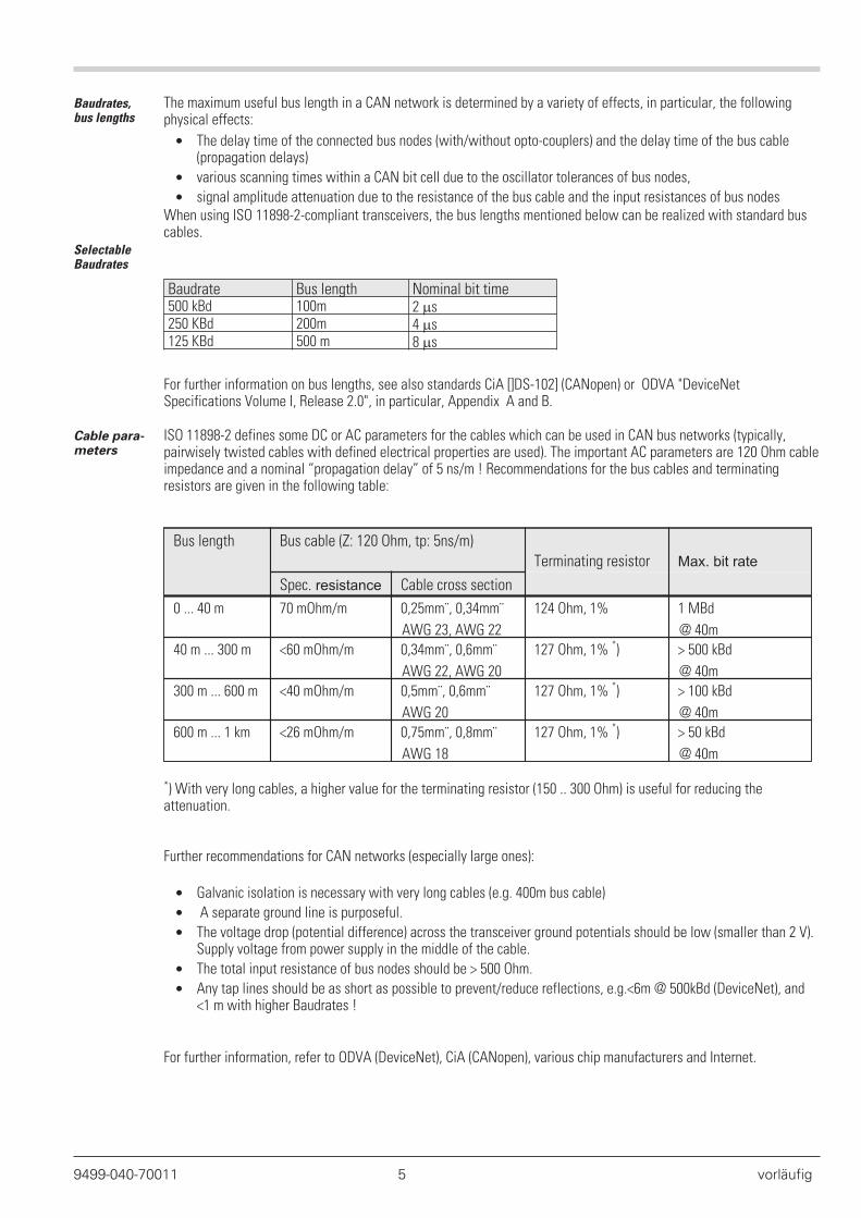
SelectableBaudrates
Baudrate Bus length Nominal bit time500 kBd 100m 2 �s250 KBd 200m 4 �s125 KBd 500 m 8 �s
For further information on bus lengths, see also standards CiA []DS-102] (CANopen) or ODVA "DeviceNetSpecifications Volume I, Release 2.0", in particular, Appendix A and B.
Cable para-meters
ISO 11898-2 defines some DC or AC parameters for the cables which can be used in CAN bus networks (typically,pairwisely twisted cables with defined electrical properties are used). The important AC parameters are 120 Ohm cableimpedance and a nominal “propagation delay” of 5 ns/m ! Recommendations for the bus cables and terminatingresistors are given in the following table:
Bus length Bus cable (Z: 120 Ohm, tp: 5ns/m)
Terminating resistor Max. bit rate
Spec. resistance Cable cross section
0 ... 40 m 70 mOhm/m 0,25mm¨, 0,34mm¨
AWG 23, AWG 22
124 Ohm, 1% 1 MBd
@ 40m
40 m ... 300 m <60 mOhm/m 0,34mm¨, 0,6mm¨
AWG 22, AWG 20
127 Ohm, 1% *) > 500 kBd
@ 40m
300 m ... 600 m <40 mOhm/m 0,5mm¨, 0,6mm¨
AWG 20
127 Ohm, 1% *) > 100 kBd
@ 40m
600 m ... 1 km <26 mOhm/m 0,75mm¨, 0,8mm¨
AWG 18
127 Ohm, 1% *) > 50 kBd
@ 40m
*) With very long cables, a higher value for the terminating resistor (150 .. 300 Ohm) is useful for reducing theattenuation.
Further recommendations for CAN networks (especially large ones):
• Galvanic isolation is necessary with very long cables (e.g. 400m bus cable)
• A separate ground line is purposeful.
• The voltage drop (potential difference) across the transceiver ground potentials should be low (smaller than 2 V).Supply voltage from power supply in the middle of the cable.
• The total input resistance of bus nodes should be > 500 Ohm.
• Any tap lines should be as short as possible to prevent/reduce reflections, e.g.<6m @ 500kBd (DeviceNet), and<1 m with higher Baudrates !
For further information, refer to ODVA (DeviceNet), CiA (CANopen), various chip manufacturers and Internet.
9499-040-70011 5 vorläufig
. 2. Hints for operation
2.1. Connecting the interface, signification of indicator LEDs on the bus coupler
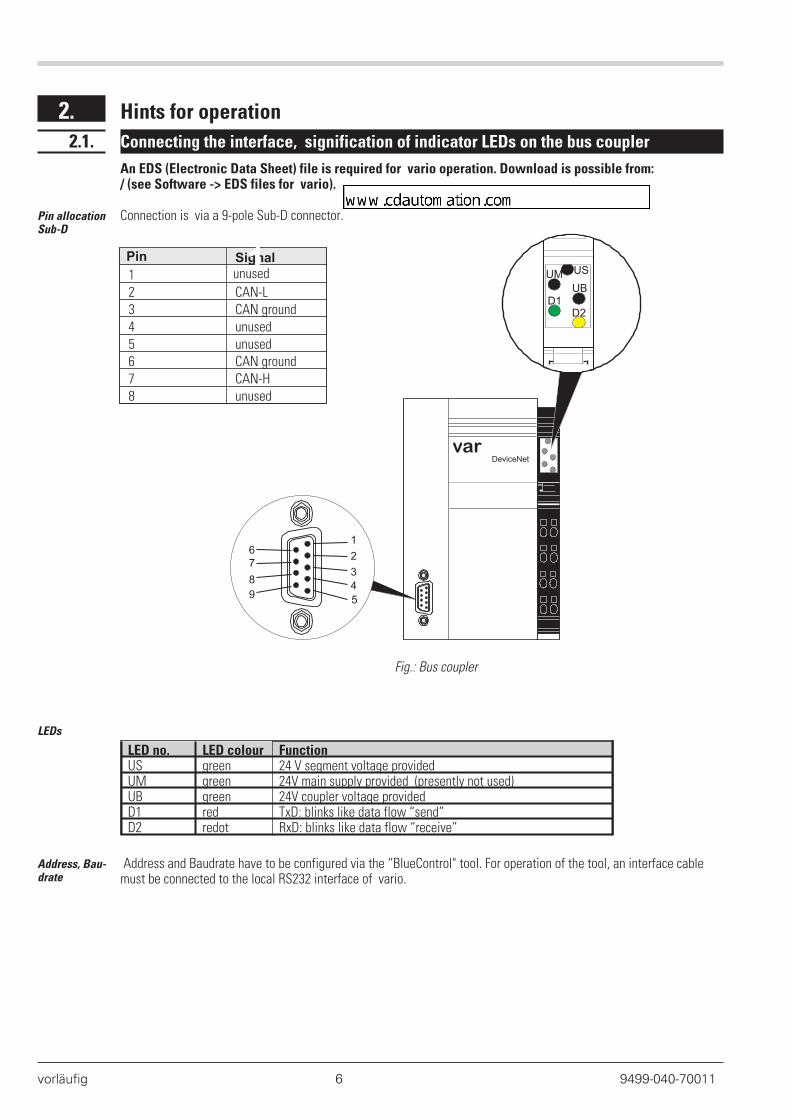
An EDS (Electronic Data Sheet) file is required for vario operation. Download is possible from:/ (see Software -> EDS files for vario).
Pin allocationSub-D
Connection is via a 9-pole Sub-D connector.
Pin Signal
1 unused
2 CAN-L3 CAN ground4 unused5 unused6 CAN ground7 CAN-H8 unused
LEDs
LED no. LED colour FunctionUS green 24 V segment voltage providedUM green 24V main supply provided (presently not used)UB green 24V coupler voltage providedD1 red TxD: blinks like data flow “send”D2 redot RxD: blinks like data flow “receive”
Address, Bau-drate
Address and Baudrate have to be configured via the “BlueControl" tool. For operation of the tool, an interface cablemust be connected to the local RS232 interface of vario.
vorläufig 6 9499-040-70011
varioDeviceNet
USUM
UBD1
D2
1
A
5
4
3
2
1
9
8
7
6
KkFig.: Bus coupler
Pc Simone Brizzi
www.cdautomation.com
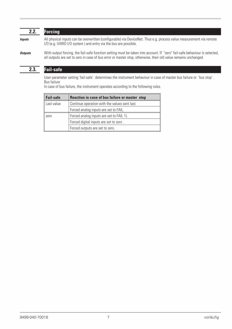
2.2. Forcing
Inputs All physical inputs can be overwritten (configurable) via DeviceNet. Thus e.g. process value measurement via remoteI/O (e.g. VARIO I/O system ) and entry via the bus are possible.
Outputs With output forcing, the fail-safe function setting must be taken into account. If "zero" fail-safe behaviour is selected,all outputs are set to zero in case of bus error or master stop, otherwise, their old value remains unchanged.
2.3. Fail-safe
User parameter setting ‘fail-safe’ determines the instrument behaviour in case of master bus failure or 'bus stop' .Bus failureIn case of bus failure, the instrument operates according to the following rules.
Fail-safe Reaction in case of bus failure or master stop
Last value Continue operation with the values sent last.
Forced analog inputs are set to FAIL.
zero Forced analog inputs are set to FAIL 1).
Forced digital inputs are set to zero .
Forced outputs are set to zero.
9499-040-70018 7 vorläufig
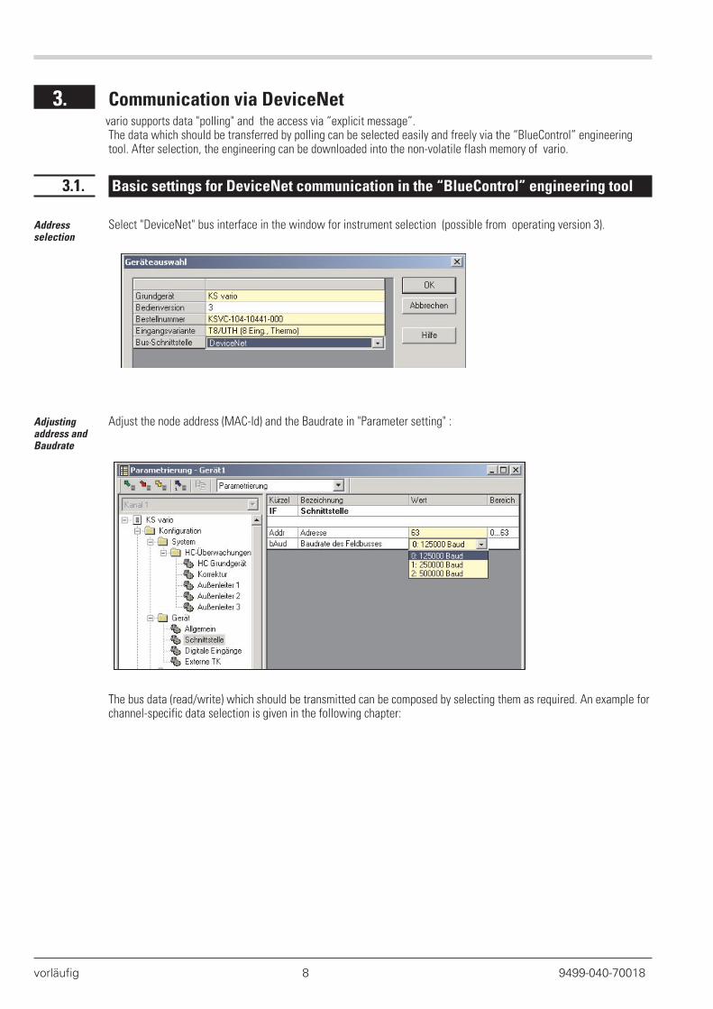
. 3. Communication via DeviceNetvario supports data "polling" and the access via “explicit message”.The data which should be transferred by polling can be selected easily and freely via the “BlueControl” engineeringtool. After selection, the engineering can be downloaded into the non-volatile flash memory of vario.
3.1. Basic settings for DeviceNet communication in the “BlueControl” engineering tool
Addressselection
Select "DeviceNet" bus interface in the window for instrument selection (possible from operating version 3).
Adjustingaddress andBaudrate
Adjust the node address (MAC-Id) and the Baudrate in "Parameter setting" :
The bus data (read/write) which should be transmitted can be composed by selecting them as required. An example forchannel-specific data selection is given in the following chapter:
vorläufig 8 9499-040-70018
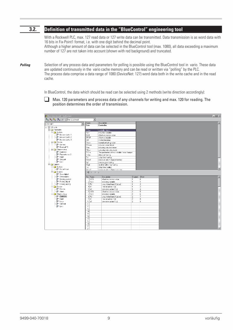
3.2. Definition of transmitted data in the “BlueControl” engineering tool
With a Rockwell PLC, max. 127 read data or 127 write data can be transmitted. Data transmission is as word data with16 bits in Fix-Point1 format, i.e. with one digit behind the decimal point.Although a higher amount of data can be selected in the BlueControl tool (max. 1080), all data exceeding a maximumnumber of 127 are not taken into account (shown with red background) and truncated.
Polling Selection of any process data and parameters for polling is possible using the BlueControl tool in vario. These dataare updated continuously in the vario cache memory and can be read or written via “polling” by the PLC.The process data comprise a data range of 1080 (DeviceNet: 127) word data both in the write cache and in the readcache.
In BlueControl, the data which should be read can be selected using 2 methods (write direction accordingly):
q Max. 120 parameters and process data of any channels for writing and max. 120 for reading. Theposition determines the order of transmission.
9499-040-70018 9 vorläufig
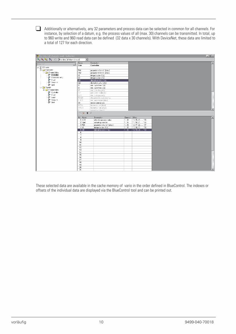
q Additionally or alternatively, any 32 parameters and process data can be selected in common for all channels. Forinstance, by selection of a datum, e.g. the process values of all (max. 30) channels can be transmitted. In total, upto 960 write and 960 read data can be defined (32 data x 30 channels). With DeviceNet, these data are limited toa total of 127 for each direction.
These selected data are available in the cache memory of vario in the order defined in BlueControl. The indexes oroffsets of the individual data are displayed via the BlueControl tool and can be printed out.
vorläufig 10 9499-040-70018
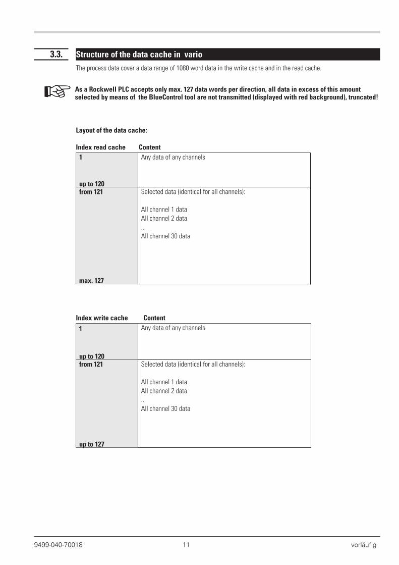
3.3. Structure of the data cache in vario
The process data cover a data range of 1080 word data in the write cache and in the read cache.
+ As a Rockwell PLC accepts only max. 127 data words per direction, all data in excess of this amountselected by means of the BlueControl tool are not transmitted (displayed with red background), truncated!
Layout of the data cache:
Index read cache Content
1
up to 120
Any data of any channels
from 121
max. 127
Selected data (identical for all channels):
All channel 1 data
All channel 2 data
...
All channel 30 data
Index write cache Content
1
up to 120
Any data of any channels
from 121
up to 127
Selected data (identical for all channels):
All channel 1 data
All channel 2 data
...
All channel 30 data
9499-040-70018 11 vorläufig
3.4. Example
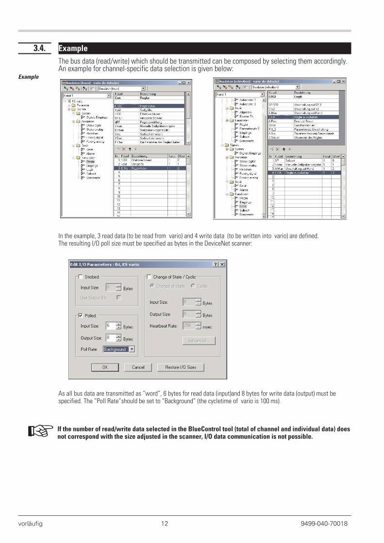
The bus data (read/write) which should be transmitted can be composed by selecting them accordingly.An example for channel-specific data selection is given below:
Example
In the example, 3 read data (to be read from vario) and 4 write data (to be written into vario) are defined.The resulting I/O poll size must be specified as bytes in the DeviceNet scanner:
As all bus data are transmitted as “word”, 6 bytes for read data (input)and 8 bytes for write data (output) must bespecified. The “Poll Rate”should be set to “Background” (the cycletime of vario is 100 ms).
+ If the number of read/write data selected in the BlueControl tool (total of channel and individual data) doesnot correspond with the size adjusted in the scanner, I/O data communication is not possible.
vorläufig 12 9499-040-70018
3.5. Communication with the PLC at the example of Rockwell with RSNetWorx
The settings required for communication of vario DeviceNet with a PLC is described at the example of a RockwellPLC and network configuration tool RSNetWorx. For further details related to the Rockwell components, see therelevant documentation.
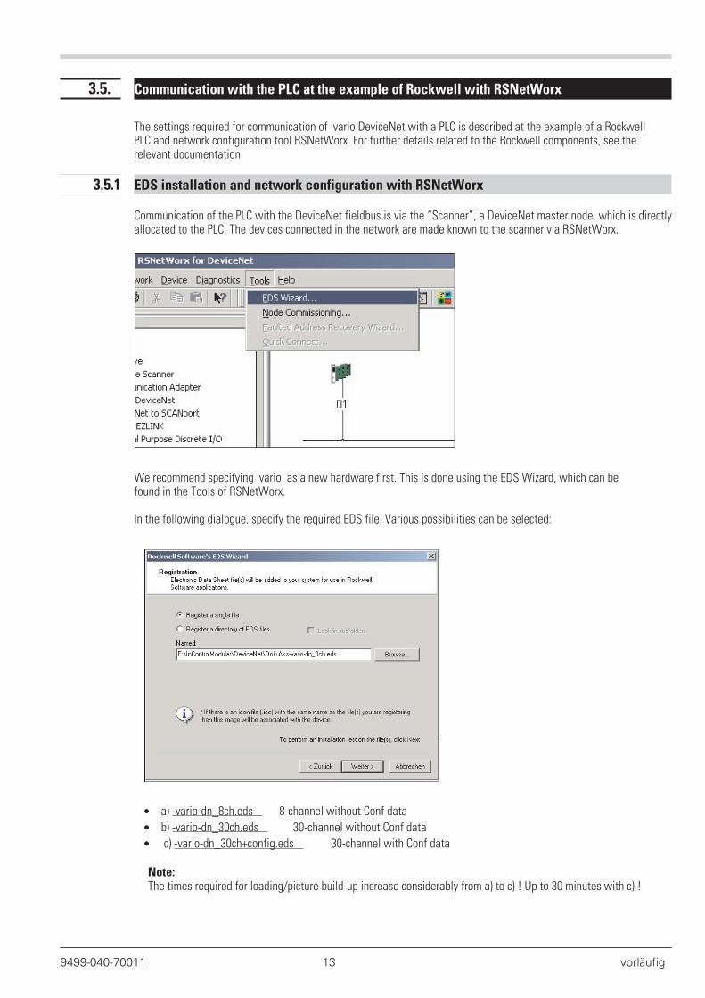
3.5.1 EDS installation and network configuration with RSNetWorx
Communication of the PLC with the DeviceNet fieldbus is via the “Scanner”, a DeviceNet master node, which is directlyallocated to the PLC. The devices connected in the network are made known to the scanner via RSNetWorx.
We recommend specifying vario as a new hardware first. This is done using the EDS Wizard, which can befound in the Tools of RSNetWorx.
In the following dialogue, specify the required EDS file. Various possibilities can be selected:
• a) -vario-dn_8ch.eds 8-channel without Conf data
• b) -vario-dn_30ch.eds 30-channel without Conf data
• c) -vario-dn_30ch+config.eds 30-channel with Conf data
Note:The times required for loading/picture build-up increase considerably from a) to c) ! Up to 30 minutes with c) !
9499-040-70011 13 vorläufig
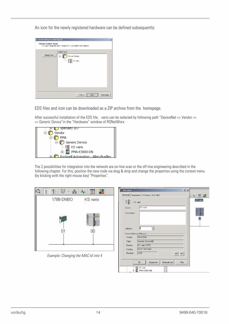
An icon for the newly registered hardware can be defined subsequently:
EDS files and icon can be downloaded as a ZIP archive from the homepage.
After successful installation of the EDS file, vario can be selected by following path “DeviceNet => Vendor => => Generic Device”in the “Hardware” window of RSNetWorx:
The 2 possibilities for integration into the network are on-line scan or the off-line engineering described in thefollowing chapter. For this, position the new node via drag & drop and change the properties using the context menu(by klicking with the right mouse key) “Properties”.
vorläufig 14 9499-040-70018
Example: Changing the MAC-Id into 4
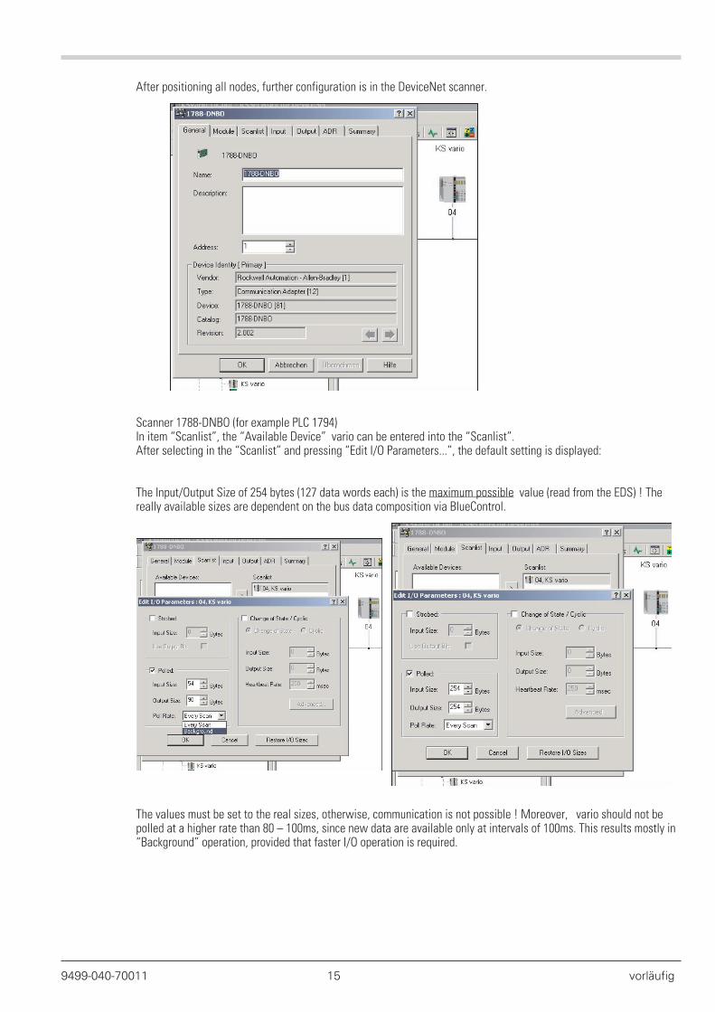
After positioning all nodes, further configuration is in the DeviceNet scanner.
Scanner 1788-DNBO (for example PLC 1794)In item “Scanlist”, the “Available Device” vario can be entered into the “Scanlist”.After selecting in the “Scanlist” and pressing “Edit I/O Parameters...”, the default setting is displayed:
The Input/Output Size of 254 bytes (127 data words each) is the maximum possible value (read from the EDS) ! Thereally available sizes are dependent on the bus data composition via BlueControl.
The values must be set to the real sizes, otherwise, communication is not possible ! Moreover, vario should not bepolled at a higher rate than 80 – 100ms, since new data are available only at intervals of 100ms. This results mostly in“Background” operation, provided that faster I/O operation is required.
9499-040-70011 15 vorläufig
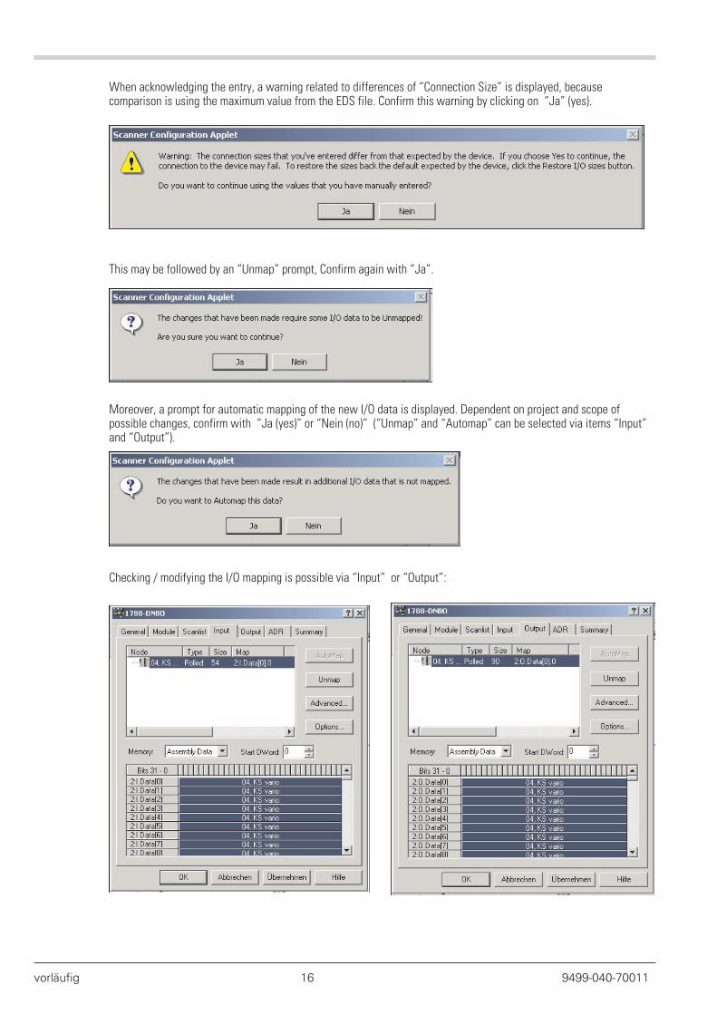
When acknowledging the entry, a warning related to differences of “Connection Size” is displayed, becausecomparison is using the maximum value from the EDS file. Confirm this warning by clicking on “Ja” (yes).
This may be followed by an “Unmap” prompt, Confirm again with “Ja”.
Moreover, a prompt for automatic mapping of the new I/O data is displayed. Dependent on project and scope ofpossible changes, confirm with “Ja (yes)” or “Nein (no)” (“Unmap” and “Automap” can be selected via items “Input”and “Output”).
Checking / modifying the I/O mapping is possible via “Input” or “Output”:
vorläufig 16 9499-040-70011
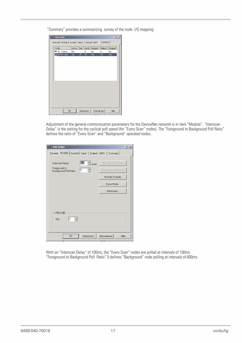
“Summary” provides a summarizing survey of the node I/O mapping:
Adjustment of the general communication parameters for the DeviceNet network is in item “Module”. “InterscanDelay” is the setting for the cyclical poll speed (for “Every Scan” nodes). The “Foreground to Background Poll Ratio”defines the ratio of “Every Scan” and “Background” operated nodes.
With an “Interscan Delay” of 100ms, the “Every Scan” nodes are polled at intervals of 100ms.“Foreground to Background Poll Ratio” 5 defines “Background” node polling at intervals of 600ms.
9499-040-70018 17 vorläufig
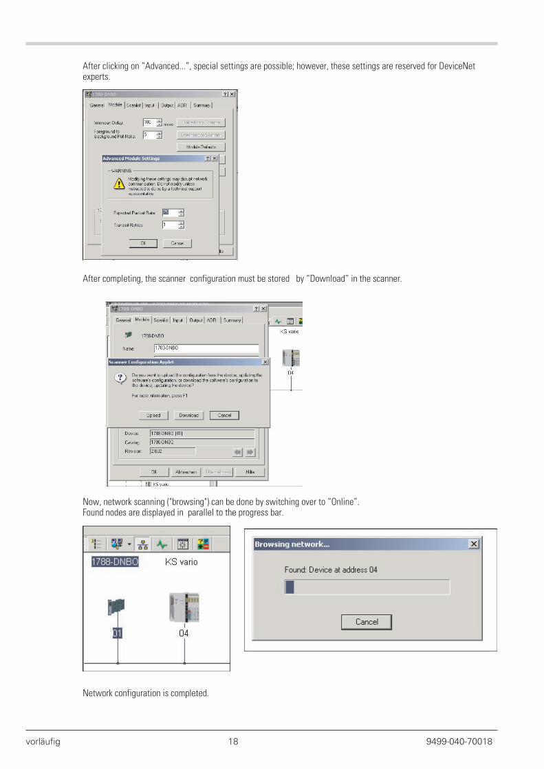
After clicking on “Advanced...”, special settings are possible; however, these settings are reserved for DeviceNetexperts.
After completing, the scanner configuration must be stored by “Download” in the scanner.
Now, network scanning ("browsing") can be done by switching over to “Online”.Found nodes are displayed in parallel to the progress bar.
Network configuration is completed.
vorläufig 18 9499-040-70018
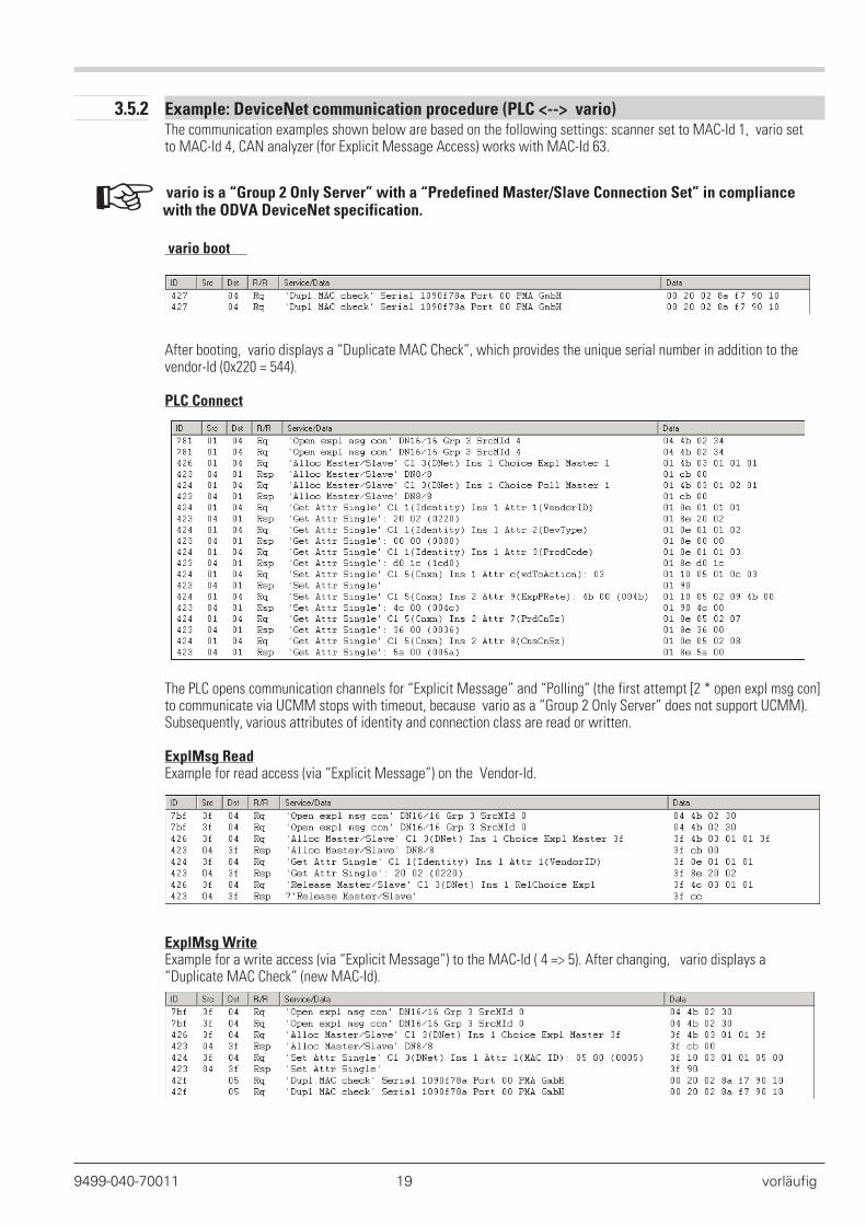
3.5.2 Example: DeviceNet communication procedure (PLC <--> vario)The communication examples shown below are based on the following settings: scanner set to MAC-Id 1, vario setto MAC-Id 4, CAN analyzer (for Explicit Message Access) works with MAC-Id 63.
+ vario is a “Group 2 Only Server” with a “Predefined Master/Slave Connection Set” in compliancewith the ODVA DeviceNet specification.
vario boot
After booting, vario displays a “Duplicate MAC Check”, which provides the unique serial number in addition to thevendor-Id (0x220 = 544).
PLC Connect
The PLC opens communication channels for “Explicit Message” and “Polling” (the first attempt [2 * open expl msg con]to communicate via UCMM stops with timeout, because vario as a “Group 2 Only Server” does not support UCMM).Subsequently, various attributes of identity and connection class are read or written.
ExplMsg ReadExample for read access (via “Explicit Message”) on the Vendor-Id.
ExplMsg WriteExample for a write access (via “Explicit Message”) to the MAC-Id ( 4 => 5). After changing, vario displays a“Duplicate MAC Check” (new MAC-Id).
9499-040-70011 19 vorläufig
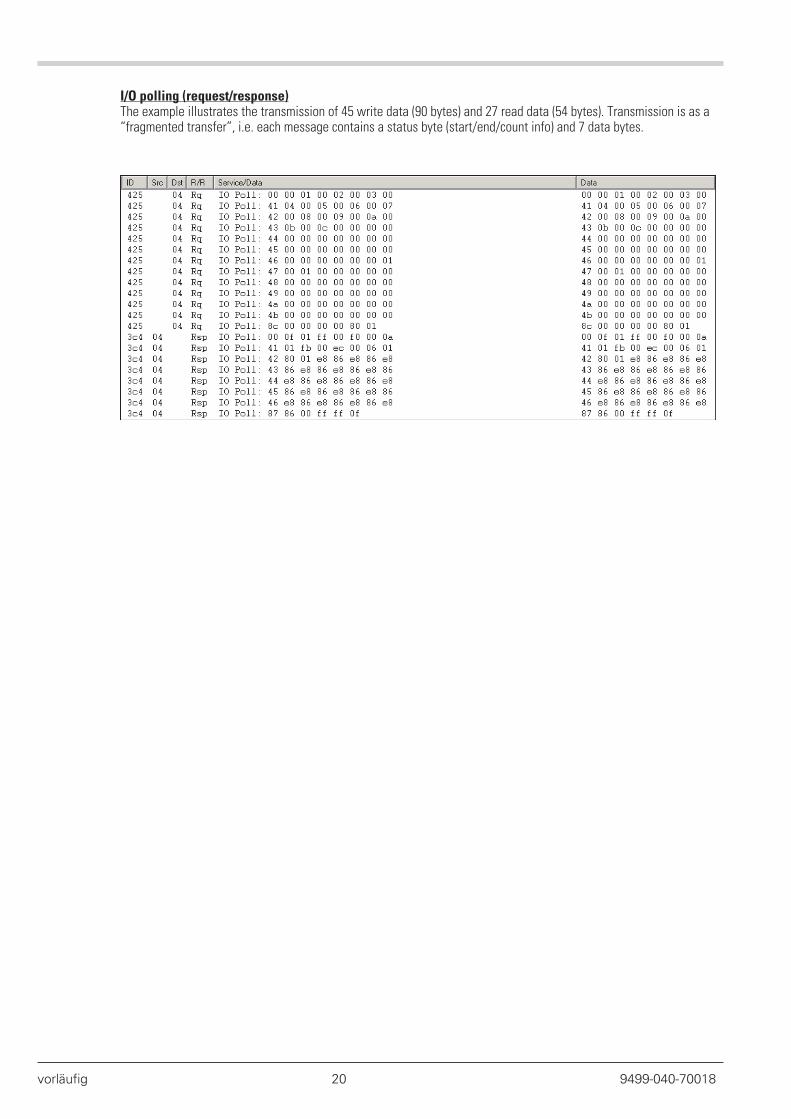
I/O polling (request/response)The example illustrates the transmission of 45 write data (90 bytes) and 27 read data (54 bytes). Transmission is as a“fragmented transfer”, i.e. each message contains a status byte (start/end/count info) and 7 data bytes.
vorläufig 20 9499-040-70018
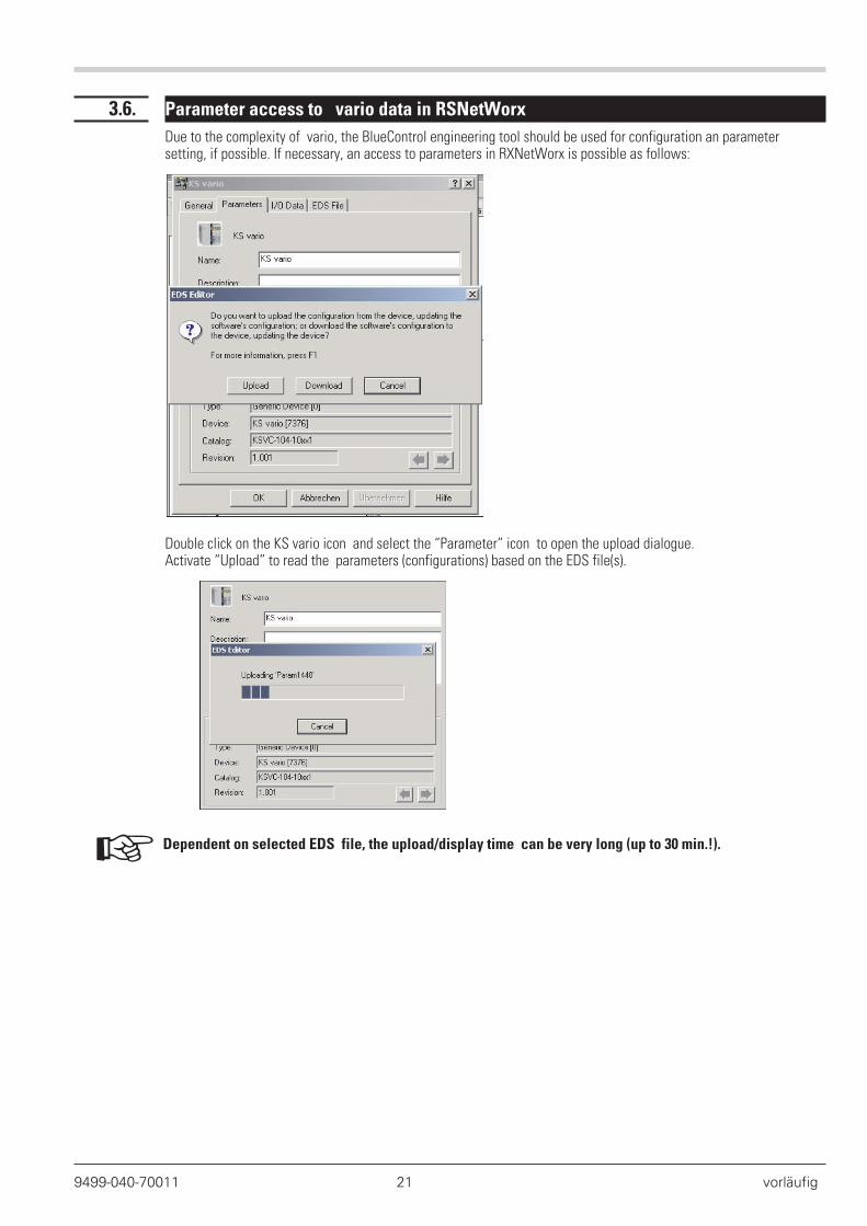
3.6. Parameter access to vario data in RSNetWorx
Due to the complexity of vario, the BlueControl engineering tool should be used for configuration an parametersetting, if possible. If necessary, an access to parameters in RXNetWorx is possible as follows:
Double click on the KS vario icon and select the “Parameter” icon to open the upload dialogue.Activate “Upload” to read the parameters (configurations) based on the EDS file(s).
+ Dependent on selected EDS file, the upload/display time can be very long (up to 30 min.!).
9499-040-70011 21 vorläufig
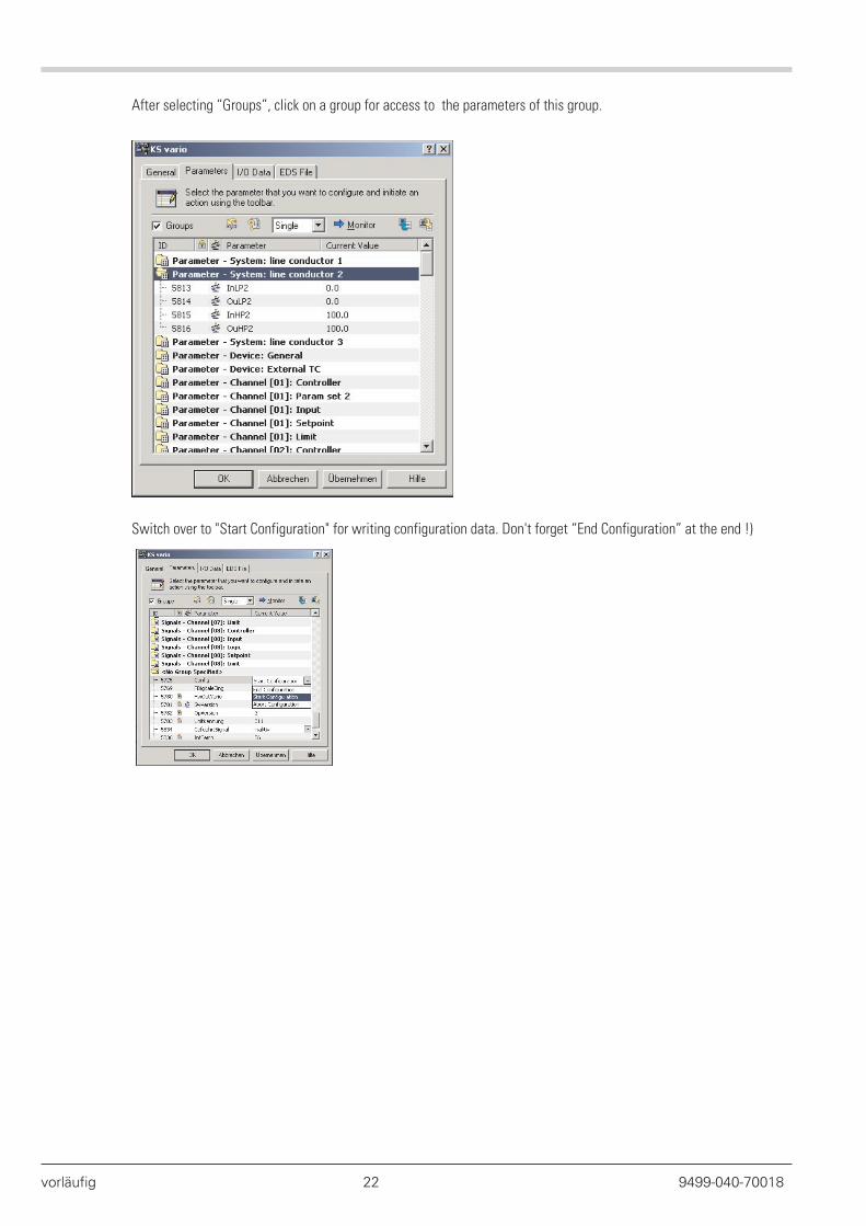
After selecting “Groups”, click on a group for access to the parameters of this group.
Switch over to "Start Configuration" for writing configuration data. Don't forget “End Configuration” at the end !)
vorläufig 22 9499-040-70018
. 4. vario DeviceNet “Object directory”
Apart from the standard DeviceNet classes (Identity, Message Router, DeviceNet, Assembly, Connection ...), which arenot described in detail in this manual, there are also manufacturer-specific classes, instances and attributes.
The following table provides a survey of vario data objects ( parameters, signals, configurations) and and related"addresses” (class, instance, attribute). Bus access to these data is possible via “Explicit Messaging”.
For a description of the individual data (not addresses), see the vario parameter table.
+ A detailed address survey of all data is given in document::Parameter table for vario (9499-040-72918) - available from Feb. 2005
- and on request up to this date
9499-040-70018 23 vorläufig

Subject to alterations without notice. Bei Änderungen erfolgt keine Mitteilung. Sous réserve de modifications sans avis préalable.
A4

![3- Buscoupler [Compatibility Mode]](https://static.fdocuments.in/doc/165x107/55cf9abd550346d033a32e88/3-buscoupler-compatibility-mode.jpg)