Device Data Model for TR-069 - Broadband Forum · Broadband Forum Technical Report is subject to...
88
TECHNICAL REPORT © The Broadband Forum. All rights reserved. TR-181 Device Data Model for TR-069 Issue: 2 Amendment 2 Issue Date: February 2011
Transcript of Device Data Model for TR-069 - Broadband Forum · Broadband Forum Technical Report is subject to...

TECHNICAL REPORT
© The Broadband Forum. All rights reserved.
TR-181 Device Data Model for TR-069
Issue: 2 Amendment 2
Issue Date: February 2011
Device Data Model for TR-069 TR-181 Issue 2 Amendment 2
February 2011 © The Broadband Forum. All rights reserved 2 of 88
Notice The Broadband Forum is a non-profit corporation organized to create guidelines for broadband network system development and deployment. This Broadband Forum Technical Report has been approved by members of the Forum. This Broadband Forum Technical Report is not binding on the Broadband Forum, any of its members, or any developer or service provider. This Broadband Forum Technical Report is subject to change, but only with approval of members of the Forum. This Technical Report is copyrighted by the Broadband Forum, and all rights are reserved. Portions of this Technical Report may be copyrighted by Broadband Forum members. This Broadband Forum Technical Report is provided AS IS, WITH ALL FAULTS. ANY PERSON HOLDING A COPYRIGHT IN THIS BROADBAND FORUM TECHNICAL REPORT, OR ANY PORTION THEREOF, DISCLAIMS TO THE FULLEST EXTENT PERMITTED BY LAW ANY REPRESENTATION OR WARRANTY, EXPRESS OR IMPLIED, INCLUDING, BUT NOT LIMITED TO, ANY WARRANTY: (A) OF ACCURACY, COMPLETENESS, MERCHANTABILITY, FITNESS FOR A
PARTICULAR PURPOSE, NON-INFRINGEMENT, OR TITLE; (B) THAT THE CONTENTS OF THIS BROADBAND FORUM TECHNICAL REPORT
ARE SUITABLE FOR ANY PURPOSE, EVEN IF THAT PURPOSE IS KNOWN TO THE COPYRIGHT HOLDER;
(C) THAT THE IMPLEMENTATION OF THE CONTENTS OF THE TECHNICAL REPORT WILL NOT INFRINGE ANY THIRD PARTY PATENTS, COPYRIGHTS, TRADEMARKS OR OTHER RIGHTS.
By using this Broadband Forum Technical Report, users acknowledge that implementation may require licenses to patents. The Broadband Forum encourages but does not require its members to identify such patents. For a list of declarations made by Broadband Forum member companies, please see http://www.broadband-forum.org. No assurance is given that licenses to patents necessary to implement this Technical Report will be available for license at all or on reasonable and non-discriminatory terms. ANY PERSON HOLDING A COPYRIGHT IN THIS BROADBAND FORUM TECHNICAL REPORT, OR ANY PORTION THEREOF, DISCLAIMS TO THE FULLEST EXTENT PERMITTED BY LAW (A) ANY LIABILITY (INCLUDING DIRECT, INDIRECT, SPECIAL, OR CONSEQUENTIAL DAMAGES UNDER ANY LEGAL THEORY) ARISING FROM OR RELATED TO THE USE OF OR RELIANCE UPON THIS TECHNICAL REPORT; AND (B) ANY OBLIGATION TO UPDATE OR CORRECT THIS TECHNICAL REPORT. Broadband Forum Technical Reports may be copied, downloaded, stored on a server or otherwise re-distributed in their entirety only, and may not be modified without the advance written permission of the Broadband Forum. The text of this notice must be included in all copies of this Broadband Forum Technical Report.

Device Data Model for TR-069 TR-181 Issue 2 Amendment 2
February 2011 © The Broadband Forum. All rights reserved 3 of 88
Issue History Issue Number Issue Date Issue Editor Changes Issue 2 May 2010 Paul Sigurdson, Broadband Forum
William Lupton, 2Wire Original. Defines version 2.0 of the TR-069 Device data model (Device:2.0).
Issue 2 Amendment 1
November 2010
Paul Sigurdson, Broadband Forum William Lupton, 2Wire
Added support for Software Module Management in the data model (no change to this document). Defines version 2.1 of the TR-069 Device data model (Device:2.1).
Issue 2 Amendment 2
February 2011 Paul Sigurdson, Broadband Forum William Lupton, Pace
Added support for IPv6 and Firewall in the data model (added IPv6 and Firewall Appendices to this document). Defines version 2.2 of the TR-069 Device data model (Device:2.2).
Comments or questions about this Broadband Forum Technical Report should be directed to [email protected]. Editors William Lupton Pace Paul Sigurdson Broadband Forum
BroadbandHome™ Working Group Chairs
Greg Bathrick Heather Kirksey
PMC-Sierra Alcatel-Lucent
Vice Chair Jason Walls UNH
Device Data Model for TR-069 TR-181 Issue 2 Amendment 2
February 2011 © The Broadband Forum. All rights reserved 4 of 88
Table of Contents EXECUTIVE SUMMARY .......................................................................................................... 8 1 PURPOSE AND SCOPE ........................................................................................................ 9
1.1 PURPOSE ............................................................................................................................. 9 1.2 SCOPE ................................................................................................................................. 9
2 REFERENCES AND TERMINOLOGY ............................................................................ 14 2.1 CONVENTIONS .................................................................................................................. 14 2.2 REFERENCES ..................................................................................................................... 14 2.3 DEFINITIONS ..................................................................................................................... 17 2.4 ABBREVIATIONS ............................................................................................................... 18
3 TECHNICAL REPORT IMPACT ..................................................................................... 19 3.1 ENERGY EFFICIENCY ......................................................................................................... 19 3.2 IPV6 .................................................................................................................................. 19 3.3 SECURITY .......................................................................................................................... 19
4 ARCHITECTURE ................................................................................................................ 20 4.1 INTERFACE LAYERS .......................................................................................................... 20 4.2 INTERFACE OBJECTS .......................................................................................................... 21
4.2.1 Lower Layers ............................................................................................................ 23 4.2.2 Administrative and Operational Status ..................................................................... 24 4.2.3 Stacking and Operational Status .............................................................................. 25 4.2.4 Vendor-specific Interface Objects ............................................................................. 25
4.3 INTERFACESTACK TABLE ................................................................................................. 26 5 PARAMETER DEFINITIONS ........................................................................................... 30 ANNEX A: BRIDGING AND QUEUING ............................................................................. 31
A.1 QUEUING AND BRIDGING MODEL .................................................................................... 31 A.1.1 Packet Classification ................................................................................................ 31 A.1.1.1 Classification Order .............................................................................................. 32 A.1.1.2 Dynamic Application Specific Classification ........................................................ 33 A.1.1.3 Classification Outcome ......................................................................................... 34 A.1.2 Policing ..................................................................................................................... 34 A.1.3 Queuing and Scheduling ........................................................................................... 34 A.1.4 Bridging .................................................................................................................... 35 A.1.4.1 Filtering ................................................................................................................. 36 A.1.4.2 Filter Order ........................................................................................................... 36
A.2 DEFAULT LAYER 2/3 QOS MAPPING ................................................................................ 37 A.3 URN DEFINITIONS FOR APP AND FLOW TABLES .............................................................. 38
A.3.1 App ProtocolIdentifier .............................................................................................. 38 A.3.2 Flow Type ................................................................................................................. 38 A.3.3 Flow TypeParameters .............................................................................................. 39
APPENDIX I: EXAMPLE RG QUEUING ARCHITECTURE (FROM TR-059) ........... 40

Device Data Model for TR-069 TR-181 Issue 2 Amendment 2
February 2011 © The Broadband Forum. All rights reserved 5 of 88
APPENDIX II: USE OF BRIDGING OBJECTS FOR VLAN TAGGING ....................... 42 II.1 TAGGED LAN TO TAGGED WAN TRAFFIC (VLAN BRIDGING) ....................................... 43 II.2 TAGGED LAN TO TAGGED WAN TRAFFIC (SPECIAL CASE WITH VLAN ID TRANSLATION) 44 II.3 UNTAGGED LAN TO TAGGED WAN TRAFFIC .................................................................. 47 II.4 INTERNALLY GENERATED TO TAGGED WAN TRAFFIC .................................................... 48 II.5 OTHER ISSUES .................................................................................................................. 49 II.5.1 MORE THAN ONE DOWNSTREAM INTERFACE IN A BRIDGE ............................................ 50 II.5.2 802.1D (RE)-MARKING ................................................................................................. 51 II.5.3 MORE THAN ONE VLAN ID TAG ADMITTED ON THE SAME DOWNSTREAM INTERFACE 52
APPENDIX III: WI-FI THEORY OF OPERATION .......................................................... 55 III.1 MULTI-RADIO AND MULTI-BAND WI-FI RADIO DEVICES ................................................ 55 III.2 DEFINITIONS ................................................................................................................... 55 III.3 NUMBER OF INSTANCES OF WIFI.RADIO OBJECT ............................................................ 55 III.4 SUPPORTEDFREQUENCYBANDS AND OPERATINGFREQUENCYBAND .............................. 56 III.5 BEHAVIOR OF DUAL-BAND RADIOS WHEN OPERATINGFREQUENCYBAND CHANGED ..... 56 III.6 SUPPORTEDSTANDARDS AND OPERATINGSTANDARDS ................................................... 56
APPENDIX IV: USE CASES ................................................................................................. 58 IV.1 CREATE A WAN CONNECTION ....................................................................................... 58 IV.2 MODIFY A WAN CONNECTION ....................................................................................... 58 IV.3 DELETE A WAN CONNECTION ....................................................................................... 59 IV.4 DISCOVER WHETHER THE DEVICE IS A GATEWAY ........................................................... 59 IV.5 PROVIDE EXTENDED HOME NETWORKING TOPOLOGY VIEW ......................................... 60 IV.6 DETERMINE CURRENT INTERFACES CONFIGURATION ..................................................... 60 IV.7 CREATE A WLAN CONNECTION ..................................................................................... 60 IV.8 DELETE A WLAN CONNECTION ..................................................................................... 61 IV.9 CONFIGURE A DHCP CLIENT AND SERVER .................................................................... 61 IV.9.1 DHCP CLIENT CONFIGURATION (ACME DEVICES) .................................................... 61 IV.9.2 DHCP SERVER CONFIGURATION (GATEWAY) ............................................................. 61 IV.10 RECONFIGURE AN EXISTING INTERFACE ....................................................................... 62
APPENDIX V: IPV6 DATA MODELING THEORY OF OPERATION .......................... 64 V.1 IPV6 OVERVIEW ............................................................................................................... 64 V.2 DATA MODEL OVERVIEW ................................................................................................ 65 V.3 ENABLING IPV6 ............................................................................................................... 68 V.4 CONFIGURING UPSTREAM IP INTERFACES ....................................................................... 68 V.4.1 CONFIGURATION MESSAGES SENT OUT THE UPSTREAM IP INTERFACE ........................ 69 V.4.2 IPV6 PREFIXES .............................................................................................................. 69 V.4.3 IPV6 ADDRESSES .......................................................................................................... 70 V.5 CONFIGURING DOWNSTREAM IP INTERFACES .................................................................. 70 V.5.1 IPV6 PREFIXES .............................................................................................................. 70 V.5.2 IPV6 ADDRESSES .......................................................................................................... 71 V.6 DEVICE INTERACTIONS .................................................................................................... 72 V.6.1 ACTIVE CONFIGURATION .............................................................................................. 72
Device Data Model for TR-069 TR-181 Issue 2 Amendment 2
February 2011 © The Broadband Forum. All rights reserved 6 of 88
V.6.2 MONITORING ................................................................................................................. 73 V.7 CONFIGURING IPV6 ROUTING AND FORWARDING ............................................................ 73 V.8 CONFIGURING IPV6 ROUTING AND FORWARDING ............................................................ 74
APPENDIX VI: 6RD THEORY OF OPERATION ............................................................. 79 VI.1 RFC 5969 CONFIGURATION PARAMETERS ..................................................................... 79 VI.2 INTERNAL CONFIGURATION PARAMETERS ...................................................................... 79 VI.3 IPV4 ADDRESS SOURCE .................................................................................................. 79 VI.4 SENDING ALL TRAFFIC TO THE BORDER RELAY SERVER ................................................ 80 VI.5 INTERNAL TREATMENT OF IPV6 PACKETS ...................................................................... 81
APPENDIX VII: DUAL-STACK LITE THEORY OF OPERATION .............................. 83 VII.1 INTERNAL TREATMENT OF IPV4 PACKETS ..................................................................... 83
APPENDIX VIII: ADVANCED FIREWALL EXAMPLE CONFIGURATION ............. 85
Device Data Model for TR-069 TR-181 Issue 2 Amendment 2
February 2011 © The Broadband Forum. All rights reserved 7 of 88
List of Figures Figure 1 – Device:2 Data Model Structure – Overview ............................................................... 10 Figure 2 – Device:2 Data Model Structure – Device Level .......................................................... 11 Figure 3 – Device:2 Data Model Structure – Interface Stack and Networking Technologies ..... 12 Figure 4 – Device:2 Data Model Structure – Applications and Protocols .................................... 13 Figure 5 – OSI Layers and Interface Objects ............................................................................... 21 Figure 6 – Interface LowerLayers ................................................................................................. 24 Figure 7 – Ignoring a Vendor-specific Interface Object in the Stack ........................................... 26 Figure 8 – Ignoring a Vendor-specific Interface Object in the Stack (multiple sub-objects) ....... 26 Figure 9 – Simple Router Example (Interfaces Visualized) ......................................................... 28 Figure 10 – Queuing Model of a Device ...................................................................................... 31 Figure 11 – Queuing and Scheduling Example for RG ................................................................ 41 Figure 12 – Examples of VLAN configuration based on Bridging and VLAN Termination
objects ................................................................................................................................... 42 Figure 13 – Bridge 1 model .......................................................................................................... 43 Figure 14 – Bridge 2 model .......................................................................................................... 45 Figure 15 – Bridge 3 model .......................................................................................................... 47 Figure 16 – VLAN Termination model ........................................................................................ 49 Figure 17 – Bridge 1 model .......................................................................................................... 50 Figure 18 – Example of VLAN configuration in a 2 box scenario ............................................... 53 Figure 19 – Bridge 1,2,3 model .................................................................................................... 53 Figure 20 – Relationship of Protocols to Data Model .................................................................. 67 Figure 21 – Internal Relationships of IPv6 Addresses and Prefixes ............................................. 68 Figure 22 – Sample 6rd Routing and Forwarding ........................................................................ 82 Figure 23 – Sample Flow of Upstream Tunneled Traffic through Device QoS ........................... 82 Figure 24 – Sample DS-Lite Routing and Forwarding ................................................................. 84 List of Tables Table 1 – Simple Router Example (InterfaceStack table) ............................................................ 27 Table 2 – Simple Router Example (Interface LowerLayers) ........................................................ 29 Table 3 – Device:2 Data Model Versions ..................................................................................... 30 Table 4 – Default Layer 2/3 QoS Mapping .................................................................................. 37 Table 5 – ProtocolIdentifer URNs ................................................................................................ 38 Table 6 – Flow TypeParameters values for flow type urn:dslforum-org:pppoe ........................... 39 Table 7 – Tagged LAN to tagged WAN configuration ................................................................ 43 Table 8 – Tagged LAN to tagged WAN configuration (VLAN ID translation) .......................... 45 Table 9 – Untagged LAN to tagged WAN configuration ............................................................. 47 Table 10 – Internally generated to tagged WAN configuration ................................................... 49 Table 11 – Configuration to be added to Table 7 ......................................................................... 51 Table 12 – 802.1D (re-)marking ................................................................................................... 52 Table 13 – More than one VLAN ID tag admitted on the same Downstream interface .............. 54 Table 14 – RFC 5969 Configuration Parameter Mapping ............................................................ 79 Table 15 – Draft Configuration Parameter Mapping .................................................................... 83

Device Data Model for TR-069 TR-181 Issue 2 Amendment 2
February 2011 © The Broadband Forum. All rights reserved 8 of 88
Executive Summary This Technical Report defines version 2 of the TR-069 [2] Device data model (Device:2). The Device:2 data model applies to all types of TR-069-enabled devices, including End Devices, Residential Gateways, and other Network Infrastructure Devices. It represents a next generation evolution that supersedes both Device:1 and InternetGatewayDevice:1. The evolution to Device:2 was necessary in order resolve some fundamental limitations in the InternetGatewayDevice:1 data model, which proved to be inflexible and caused problems in representing complex device configurations. However, in defining this next generation data model, care has been taken to ensure that all InternetGatewayDevice:1 and Device:1 functionality has been covered. Legacy installations can continue to make use of the InternetGatewayDevice:1 and Device:1 data models, which are still valid. The Device:2 data model defined in this Technical Report consists of a set of data objects covering things like basic device information, time-of-day configuration, network interface and protocol stack configuration, routing and bridging management, throughput statistics, and diagnostic tests. It also defines a baseline profile that specifies a minimum level of data model support. The cornerstone of the Device:2 data model is the interface stacking mechanism. Network interfaces and protocol layers are modeled as independent data objects that can be stacked, one on top of the other, into whatever configuration a device might support.

Device Data Model for TR-069 TR-181 Issue 2 Amendment 2
February 2011 © The Broadband Forum. All rights reserved 9 of 88
1 Purpose and Scope
1.1 Purpose This Technical Report defines version 2 of the TR-069 [2] Device data model (Device:2). The Device:2 data model applies to all types of TR-069-enabled devices, including End Devices, Residential Gateways, and other Network Infrastructure Devices. It represents a next generation evolution that supersedes both Device:1 and InternetGatewayDevice:1. The evolution to Device:2 was necessary in order resolve some fundamental limitations in the InternetGatewayDevice:1 data model, which proved to be inflexible and caused problems in representing complex device configurations. However, in defining this next generation data model, care has been taken to ensure that all InternetGatewayDevice:1 and Device:1 functionality has been covered. Legacy installations can continue to make use of the InternetGatewayDevice:1 and Device:1 data models, which are still valid.
1.2 Scope The Device:2 data model defined in this Technical Report consists of a set of data objects covering things like basic device information, time-of-day configuration, network interface and protocol stack configuration, routing and bridging management, throughput statistics, and diagnostic tests. It also defines a baseline profile that specifies a minimum level of data model support. The cornerstone of the Device:2 data model is the interface stacking mechanism. Network interfaces and protocol layers are modeled as independent data objects (a.k.a. interface objects) that can be stacked, one on top of the other, into whatever configuration a device might support. Figure 1 illustrates the top-level Device:2 data model structure. Figure 2, Figure 3, and Figure 4 illustrate the data model structure in greater detail. See Section 5 for the complete list of objects.
• Interface objects are indicated by a “dashed” background pattern. • Objects that reference interface objects are indicated by a “dotted” background pattern.

Device Data Model for TR-069 TR-181 Issue 2 Amendment 2
February 2011 © The Broadband Forum. All rights reserved 10 of 88
Figure 1 – Device:2 Data Model Structure – Overview

Device Data Model for TR-069 TR-181 Issue 2 Amendment 2
February 2011 © The Broadband Forum. All rights reserved 11 of 88
Figure 2 – Device:2 Data Model Structure – Device Level

Device Data Model for TR-069 TR-181 Issue 2 Amendment 2
February 2011 © The Broadband Forum. All rights reserved 12 of 88
Figure 3 – Device:2 Data Model Structure – Interface Stack and Networking Technologies

Device Data Model for TR-069 TR-181 Issue 2 Amendment 2
February 2011 © The Broadband Forum. All rights reserved 13 of 88
Figure 4 – Device:2 Data Model Structure – Applications and Protocols

Device Data Model for TR-069 TR-181 Issue 2 Amendment 2
February 2011 © The Broadband Forum. All rights reserved 14 of 88
2 References and Terminology
2.1 Conventions In this Technical Report, several words are used to signify the requirements of the specification. These words are always capitalized. More information can be found be in RFC 2119 [1]. MUST This word, or the term “REQUIRED”, means that the definition is an
absolute requirement of the specification. MUST NOT This phrase means that the definition is an absolute prohibition of the
specification. SHOULD This word, or the adjective “RECOMMENDED”, means that there could
exist valid reasons in particular circumstances to ignore this item, but the full implications need to be understood and carefully weighed before choosing a different course.
SHOULD NOT This phrase, or the phrase “NOT RECOMMENDED” means that there could exist valid reasons in particular circumstances when the particular behavior is acceptable or even useful, but the full implications need to be understood and the case carefully weighed before implementing any behavior described with this label.
MAY This word, or the adjective “OPTIONAL”, means that this item is one of an allowed set of alternatives. An implementation that does not include this option MUST be prepared to inter-operate with another implementation that does include the option.
The key words “DEPRECATED” and “OBSOLETED” in this Technical Report are to be interpreted as defined in TR-106 [3].
2.2 References The following references are of relevance to this Technical Report. At the time of publication, the editions indicated were valid. All references are subject to revision; users of this Technical Report are therefore encouraged to investigate the possibility of applying the most recent edition of the references listed below. A list of currently valid Broadband Forum Technical Reports is published at www.broadband-forum.org. [1] RFC 2119, Key words for use in RFCs to Indicate Requirement Levels, IETF, 1997
[2] TR-069 Amendment 3, CPE WAN Management Protocol, Broadband Forum, 2010 [3] TR-106 Amendment 5, Data Model Template for TR-069-Enabled Devices, Broadband
Forum, 2010 [4] RFC 3986, Uniform Resource Identifier (URI): Generic Syntax, IETF, 2005

Device Data Model for TR-069 TR-181 Issue 2 Amendment 2
February 2011 © The Broadband Forum. All rights reserved 15 of 88
[5] XML Schema Part 0: Primer Second Edition, W3C, 2004 [6] RFC 2863, The Interfaces Group MIB, IETF, 2000
[7] X.200, Information technology - Open Systems Interconnection - Basic Reference Model: The basic model, ITU-T, 1994
[8] 802.1D-2004, Media Access Control (MAC) Bridges, IEEE, 2004 [9] 802.1Q-2005, Virtual Bridged Local Area Networks, IEEE, 2006
[10] RFC 2597, Assured Forwarding PHB Group, IETF, 1999 [11] RFC 3246, An Expedited Forwarding PHB (Per-Hop Behavior), IETF, 2002
[12] RFC 3261, SIP: Session Initiation Protocol, IETF, 2002 [13] RFC 3435, Media Gateway Control Protocol (MGCP) - Version 1.0, IETF, 2003
[14] RFC 4566, SDP: Session Description Protocol, IETF, 2006 [15] RFC 2453, RIP Version 2, IETF, 1998
[16] RFC 2460, Internet Protocol Version 6 (IPv6) Specification, IETF, 1998 [17] RFC 2464, Transmission of IPv6 Packets over Ethernet Networks, IETF, 1998
[18] RFC 3315, Dynamic Host Configuration Protocol for IPv6 (DHCPv6), IETF, 2003 [19] RFC 3633, IPv6 Prefix Options for Dynamic Host Cofiguration Protocol (DHCP) version
6, IETF, 2003 [20] RFC 4191, Default Router Preferences and More-Specific Routes, IETF, 2005
[21] RFC 4193, Unique Local IPv6 Unicast Addresses, IETF, 2005 [22] RFC 4861, Neighbor Discovery for IP version 6 (IPv6), IETF, 2007
[23] RFC 4862, IPv6 Stateless Address Autoconfiguration, IETF, 2007 [24] RFC 5072, IP Version 6 over PPP, IETF, 2007
[25] RFC 5969, IPv6 Rapid Deployment on IPv4 Infrastructures (6rd) – Protocol Specification, IETF, 2010
[26] RFC 6106, IPv6 Router Advertisement Options for DNS Configuration, IETF, 2010 [27] draft-ietf-softwire-dual-stack-lite, Dual-Stack Lite Broadband Deployments Following
IPv4 Exhaustion, IETF, 2010 [28] draft-ietf-softwire-ds-lite-tunnel-option, Dynamic Host Configuration Protocol for IPv6
(DHCPv6) Options for Dual-Stack Lite, IETF, 2010 [29] TR-101, Migration to Ethernet Based DSL Aggregation, Broadband Forum, 2006
[30] TR-124 Issue 2, Functional Requirements for Broadband Residential Gateway Devices, Broadband Forum, 2010
[31] TR-177, IPv6 in the context of TR-101, Broadband Forum, 2010 [32] TR-187, IPv6 for PPP Broadband Access, Broadband Forum, 2010

Device Data Model for TR-069 TR-181 Issue 2 Amendment 2
February 2011 © The Broadband Forum. All rights reserved 16 of 88
[33] ICSA Baseline Modular Firewall Certification Criteria, Baseline module – version 4.1, ICSA Labs, 2008
[34] ICSA Residential Modular Firewall Certification Criteria, Required Services Security Policy – Residential Category module – version 4.1, ICSA Labs, 2008

Device Data Model for TR-069 TR-181 Issue 2 Amendment 2
February 2011 © The Broadband Forum. All rights reserved 17 of 88
2.3 Definitions The following terminology is used throughout this Technical Report. ACS Auto-Configuration Server. This is a component in the broadband network
responsible for auto-configuration of the CPE for advanced services.
CPE Customer Premises Equipment; refers to any TR-069-enabled [2] device and therefore covers Residential Gateways, LAN-side End Devices, and other Network Infrastructure Devices.
Component A named collection of Objects and/or Parameters and/or Profiles that can be included anywhere within a Data Model.
CWMP CPE WAN Management Protocol. Defined in TR-069 [2], CWMP is a communication protocol between an ACS and CPE that defines a mechanism for secure auto-configuration of a CPE and other CPE management functions in a common framework.
Data Model A hierarchical set of Objects and/or Parameters that define the managed objects accessible via TR-069 for a particular CPE.
Device Used here as a synonym for CPE.
DM Instance Data Model Schema instance document. This is an XML document that conforms to the DM Schema and to any additional rules specified in or referenced by the DM Schema.
DM Schema Data Model Schema. This is the XML Schema [5] that is used for defining data models for use with CWMP.
Downstream Interface
A physical interface object whose Upstream parameter is set to false, or an interface that is associated with such a physical interface via the InterfaceStack. For example, a downstream IP Interface is an IP.Interface object that is associated with an Upstream=false physical layer interface.
Interface Object A type of Object that models a network interface or protocol layer. Commonly referred to as an interface. They can be stacked, one on top of the other, using Path References in order to dynamically define the relationships between interfaces.
Object A named collection of Parameters and/or other Objects.
Parameter A name-value pair representing a manageable CPE parameter made accessible to an ACS for reading and/or writing.
Path Reference Describes how a parameter can reference another parameter or object via its path name (Section A.2.3.4/TR-106 [3]). Such a reference can be weak or strong (Section A.2.3.6/TR-106 [3]).
Upstream Interface
A physical interface object whose Upstream parameter is set to true, or an interface that is associated with such a physical interface via the InterfaceStack. For example, an upstream IP Interface is an IP.Interface object that is associated with an Upstream=true physical layer interface.

Device Data Model for TR-069 TR-181 Issue 2 Amendment 2
February 2011 © The Broadband Forum. All rights reserved 18 of 88
2.4 Abbreviations This Technical Report uses the following abbreviations: ATM Asynchronous Transfer Mode.
DHCP Dynamic Host Configuration Protocol
DSL Digital Subscriber Line.
IP Internet Protocol.
OSI Open Systems Interconnection.
PPP Point-to-Point Protocol.
PTM Packet Transfer Mode.
RG Residential Gateway
RPC Remote Procedure Call.
SSID Service Set Identifier.
URI Uniform Resource Identifier [4].
URL Uniform Resource Locator [4].

Device Data Model for TR-069 TR-181 Issue 2 Amendment 2
February 2011 © The Broadband Forum. All rights reserved 19 of 88
3 Technical Report Impact
3.1 Energy Efficiency TR-181 Issue 2 Amendment 2 has no impact on Energy Efficiency.
3.2 IPv6 TR-181 Issue 2 Amendment 2 defines IPv6 extensions1 to the Device:2 data model.
3.3 Security TR-181 Issue 2 Amendment 2 has no impact on Security.
1 Introduced in Issue 2 Amendment 2
Device Data Model for TR-069 TR-181 Issue 2 Amendment 2
February 2011 © The Broadband Forum. All rights reserved 20 of 88
4 Architecture
4.1 Interface Layers This Technical Report models network interfaces and protocol layers as independent data objects, generally referred to as interface objects (or interfaces). Interface objects can be stacked, one on top of the other, using path references in order to dynamically define the relationships between interfaces. The interface object and interface stack are concepts inspired by RFC 2863 [6]. Within the Device:2 data model, interface objects are arbitrarily restricted to definitions that operate at or below the IP network layer (i.e. layers 1 through 3 of the OSI model [7]). However, vendor-specific interface objects MAY be defined which fall outside this restricted scope. Figure 5 lists the interface objects defined in the Device:2 data model. The indicated OSI layer is non-normative; it serves as a guide only, illustrating at what level in the stack an interface object is expected to appear. However, a CPE need not support or use all interfaces, which means that the figure does not reflect all possible stacking combinations and restrictions. For example, one CPE stack might exclude DSL Bonding, while another CPE stack might include DSL Bonding but exclude Bridging, while still another might include VLANTermination under PPP, or VLANTermination under IP with no PPP, or even Ethernet Link under IP with no VLANTermination and no PPP. NOTE – Throughout this Technical Report, object names are often abbreviated in order to improve readability. For example, Device.Ethernet.VLANTermination.{i}. is the full name of a Device:2 object, but might casually be referred to as Ethernet.VLANTermination.{i} or VLANTermination.{i} or VLANTermination, just so long as the abbreviation is unambiguous (with respect to similarly named objects defined elsewhere within the data model).

Device Data Model for TR-069 TR-181 Issue 2 Amendment 2
February 2011 © The Broadband Forum. All rights reserved 21 of 88
Figure 5 – OSI Layers and Interface Objects2 3
4.2 Interface objects An interface object is a type of network interface or protocol layer. Each type of interface is modeled by a Device:2 data model table, with a row per interface instance (e.g. IP.Interface.{i} for IP Interfaces). Each interface object contains a core set of parameters and objects, which serves as the template for defining interface objects within the data model. Interface objects can also contain other parameters and sub-objects specific to the type of interface.
2 Note that, because new minor versions of the Device:2 data model can be defined without re-publishing this Technical Report, the figure is not necessarily up-to-date. 3 The Bridge.{i}.Port.{i} object models both management (upwards facing) Bridge Ports and non-management (downwards facing) Bridge Ports, where each instance is configured as one or the other. Management Bridge Ports are stacked above non-management Bridge Ports.

Device Data Model for TR-069 TR-181 Issue 2 Amendment 2
February 2011 © The Broadband Forum. All rights reserved 22 of 88
The core set of parameters consists of:
• Enable The administrative state of the interface (i.e. boolean indicating enabled or disabled)
• Status The operational state of the interface (i.e. Up, Down, Unknown, Dormant, NotPresent, LowerLayerDown, Error)
• Alias An alternate name used to identify the interface, which is assigned an initial value by the CPE but can later be chosen by the ACS
• Name The textual name used to identify the interface, which is chosen by the CPE
• LastChange The accumulated time in seconds since the interface entered its current operational state
• LowerLayers A list of path references to interface objects that are stacked immediately below the interface
Also, a core set of statistics parameters is contained within a Stats sub-object. The definition of these parameters MAY be customized for each interface type. The core set of parameters within the Stats sub-object consists of:
• BytesSent The total number of bytes transmitted out of the interface, including framing characters.
• BytesReceived The total number of bytes received on the interface, including framing characters.
• PacketsSent The total number of packets transmitted out of the interface.
• PacketsReceived The total number of packets received on the interface.
• ErrorsSent The total number of outbound packets that could not be transmitted because of errors.
• ErrorsReceived The total number of inbound packets that contained errors preventing them from being delivered to a higher-layer protocol.
• UnicastPacketsSent The total number of packets requested for transmission which were not addressed to a multicast or broadcast address at this layer, including those that were discarded or not sent.
• UnicastPacketsReceived The total number of received packets, delivered by this layer to a higher layer, which were not addressed to a multicast or broadcast address at this layer.
• DiscardPacketsSent The total number of outbound packets which were chosen to be discarded even though no errors had been detected to prevent their being transmitted.

Device Data Model for TR-069 TR-181 Issue 2 Amendment 2
February 2011 © The Broadband Forum. All rights reserved 23 of 88
• DiscardPacketsReceived The total number of inbound packets which were chosen to be discarded even though no errors had been detected to prevent their being delivered.
• MulticastPacketsSent The total number of packets that higher-layer protocols requested for transmission and which were addressed to a multicast address at this layer, including those that were discarded or not sent.
• MulticastPacketsReceived The total number of received packets, delivered by this layer to a higher layer, which were addressed to a multicast address at this layer.
• BroadcastPacketsSent The total number of packets that higher-level protocols requested for transmission and which were addressed to a broadcast address at this layer, including those that were discarded or not sent.
• BroadcastPacketsReceived The total number of received packets, delivered by this layer to a higher layer, which were addressed to a broadcast address at this layer.
• UnknownProtoPackets-Received
The total number of packets received via the interface, which were discarded because of an unknown or unsupported protocol.
NOTE – The CPE MUST reset an interface's Stats parameters (unless otherwise stated in individual object or parameter descriptions) either when the interface becomes operationally down due to a previous administrative down (i.e. the interface's Status parameter transitions to a down state after the interface is disabled) or when the interface becomes administratively up (i.e. the interface's Enable parameter transitions from false to true). Administrative and operational status is discussed in Section 4.2.2.
4.2.1 Lower Layers Each interface object can be stacked on top of zero or more other interface objects, which MUST be specified using its LowerLayers parameter. By having each interface object, in turn, reference the interface objects in its lower layer, a logical hierarchy of all interface relationships is built up. The LowerLayers parameter is a comma-separated list of path references to interface objects. Each item in the list represents an interface object that is stacked immediately below the referencing interface. If a referenced interface is deleted, the CPE MUST remove the corresponding item from this list (i.e. items in the LowerLayers parameter are strong references). These relationships between interface objects can either be set by management action, in order to specify new interface configurations, or be pre-configured within the CPE. A CPE MUST reject any attempt to set LowerLayers values that would result in an invalid or unsupported configuration. The corresponding fault response from the CPE MUST indicate this using an Invalid Parameter Value fault code (9007). See Section A.3.2.1/TR-069 [2] for further details on SetParameterValues fault responses.

Device Data Model for TR-069 TR-181 Issue 2 Amendment 2
February 2011 © The Broadband Forum. All rights reserved 24 of 88
The lowest layer in a fully configured and operational stack is generally the physical interface (e.g. DSL Line instance representing a DSL physical link). Within these physical interface objects the LowerLayers parameter will be an empty list, unless some lower layer vendor-specific interface objects are defined and present. Higher layer interface objects MAY operate without a physical layer being modeled, however this is a local matter to the CPE. Figure 6 illustrates the use of the LowerLayers parameter. A, B, C, and D represent interface objects. Interface A’s LowerLayers parameter references interfaces B and C. Interface B’s LowerLayers parameter references interface D. Interfaces C and D have no interface references specified in their LowerLayers parameters. In this way, a multi-layered interface stack is configured. If the ACS were to delete interface B, then the CPE would update interface A’s LowerLayers parameter to no longer reference interface B (and interface D would be stranded, no longer referenced by the now deleted interface B).
Figure 6 – Interface LowerLayers
4.2.2 Administrative and Operational Status NOTE – Many of the requirements outlined in this section were derived from Section 3.1.13/RFC 2863 [6]. An interface object’s Enable and Status parameters specify the current administrative and operational status of the interface, respectively. Valid values for the Status parameter are: Up, Down, Unknown, Dormant, NotPresent, LowerLayerDown, and Error. The CPE MUST do everything possible in order to follow the operational state transitions as described below. In some cases these requirements are defined as SHOULD; this is not an indication that they are optional. These transitions, and the relationship between the Enable parameter and the Status parameter, are required behavior – it is simply the timing of how long these state transitions take that is implementation specific. When the Enable parameter is false the Status parameter SHOULD normally be Down (or NotPresent or Error if there is a fault condition on the interface). Note that when the Enable parameter transitions to false, it is possible that the Status parameter’s transition to Down might occur after a small time lag if the CPE needs to first complete certain operations (e.g. finish transmitting a packet).
D
A
B C

Device Data Model for TR-069 TR-181 Issue 2 Amendment 2
February 2011 © The Broadband Forum. All rights reserved 25 of 88
When the Enable parameter is changed to true, the Status SHOULD do one of the following: • Change to Up if and only if the interface is able to transmit and receive network traffic. • Change to Dormant if and only if the interface is operable, but is waiting for external
actions before it can transmit and receive network traffic. • Change to LowerLayerDown if and only if the interface is prevented from entering the
Up state because one or more of the interfaces beneath it is down. • Remain in the Error state if there is an error or other fault condition detected on the
interface. • Remain in the NotPresent state if the interface has missing (typically hardware)
components. • Change to Unknown if the state of the interface can not be determined for some reason.
The Dormant state indicates that the interface is operable, but it is waiting for external events to occur before it can transmit/receive traffic. When such events occur, and the interface is then able to transmit/receive traffic, the Status SHOULD change to the Up state. Note that both the Up and Dormant states are considered healthy states. The Down, NotPresent, LowerLayerDown, and Error states all indicate that the interface is down. The NotPresent state indicates that the interface is down specifically because of a missing (typically hardware) component. The LowerLayerDown state indicates that the interface is stacked on top of one or more other interfaces, and that this interface is down specifically because one or more of these lower-layer interfaces is down. The Error state indicates that the interface is down because an error or other fault condition was detected on the interface.
4.2.3 Stacking and Operational Status NOTE – The requirements outlined in this section were derived from Section 3.1.14/RFC 2863 [6]. When an interface object is stacked on top of lower-layer interfaces (i.e. is not a bottommost layer in the stack), then:
• The interface SHOULD be Up if it is able to transmit/receive traffic due to one or more interfaces lower down in the stack being Up, irrespective of whether other interfaces below it are in a non-Up state (i.e. the interface is functioning in conjunction with at least some of its lower-layered interfaces).
• The interface MAY be Up or Dormant if one or more interfaces lower down in the stack are Dormant and all other interfaces below it are in a non-Up state.
• The interface is expected to be LowerLayerDown while all interfaces lower down in the stack are either Down, NotPresent, LowerLayerDown, or Error.
4.2.4 Vendor-specific Interface Objects Vendor-specific interface objects MAY be defined and used. If such objects are specified by vendors, they MUST be preceded by X_<VENDOR>_ and follow the syntax for vendor extensions used for parameter names (as defined in Section 3.3/TR-106 [3]).

Device Data Model for TR-069 TR-181 Issue 2 Amendment 2
February 2011 © The Broadband Forum. All rights reserved 26 of 88
If the ACS encounters an unknown vendor-specific interface object within a CPE’s interface stack, rather than responding with a fault, the ACS MUST proceed as if this object’s upper-layer interfaces were directly linked to its lower-layer interfaces. This applies whether the ACS encounters such an object via the InterfaceStack table (Section 4.3) or via an interface object’s LowerLayers parameter. Figure 7 illustrates a stacked vendor-specific interface object being bypassed by the ACS, where there is just one object below the vendor-specific object.
IP.Interface.1
Ethernet.Link.1
X_00256D_AB.Interface.1
IP.Interface.1
Ethernet.Link.1
IP.Interface.1
Ethernet.Link.1
X_00256D_AB.Interface.1
IP.Interface.1
Ethernet.Link.1
Figure 7 – Ignoring a Vendor-specific Interface Object in the Stack
Figure 8 illustrates a stacked vendor-specific interface object being bypassed by the ACS, where there are multiple objects below the vendor-specific object.
Bridging.Bridge.1.Port.1
[ManagementPort=true]
Bridging.Bridge.1.Port.2
[ManagementPort=false]
X_00256D_AB.Bridge.1
Bridging.Bridge.1.Port.3
[ManagementPort=false]
Bridging.Bridge.1.Port.1
[ManagementPort=false]
Bridging.Bridge.1.Port.2
[ManagementPort=false]
Bridging.Bridge.1.Port.1
[ManagementPort=true]
Bridging.Bridge.1.Port.1
[ManagementPort=true]
Bridging.Bridge.1.Port.2
[ManagementPort=false]
X_00256D_AB.Bridge.1
Bridging.Bridge.1.Port.3
[ManagementPort=false]
Bridging.Bridge.1.Port.1
[ManagementPort=false]
Bridging.Bridge.1.Port.2
[ManagementPort=false]
Bridging.Bridge.1.Port.1
[ManagementPort=true]
Figure 8 – Ignoring a Vendor-specific Interface Object in the Stack (multiple sub-objects)
4.3 InterfaceStack Table Although the interface stack can be traversed via LowerLayers parameters (as described in Section 4.2.1 Lower Layers), an alternate mechanism is provided to aid in visualizing the overall stacking relationships and to quickly access objects within the stack. The InterfaceStack table is a Device:2 data model object, namely Device.InterfaceStack.{i}. This is a read-only table whose rows are auto-generated by the CPE based on the current relationships that are configured between interface objects (via each interface instance’s LowerLayers parameter). Each table row represents a “link” between a higher-layer interface object

Device Data Model for TR-069 TR-181 Issue 2 Amendment 2
February 2011 © The Broadband Forum. All rights reserved 27 of 88
(referenced by its HigherLayer parameter) and a lower-layer interface object (referenced by its LowerLayer parameter). This means that an InterfaceStack table row’s HigherLayer and LowerLayer parameters will always both be non-null. NOTE – As a consequence, interface instances that have been stranded will not be represented within the InterfaceStack table4. It is also likely that multiple, disjoint groups of stacked interface objects will coexist within the table (for example, each IP interface will be the root of a disjoint group; unused “fragments”, e.g. a secondary DSL channel with a configured ATM PVC that isn’t attached to anything above, will linger if they remain interconnected; and finally, partially configured “fragments” can be present when an interface stack is being set up). A CPE MUST autonomously add or remove rows in the InterfaceStack table in response to the following circumstances:
• An interface’s LowerLayers parameter was updated to remove a reference to another interface (i.e. a “link” is being removed from the stack due to a SetParameterValues request).
• An interface’s LowerLayers parameter was updated to add a reference to another interface (i.e. a “link” is being added to the stack due to a SetParameterValues request).
• An interface was deleted that had referenced, or been referenced by, one other interface (i.e. a “link” is being removed from the stack due to a DeleteObject request).
• An interface was deleted that had referenced, or been referenced by, multiple interfaces (i.e. multiple “links” are being removed from the stack due to a DeleteObject request).
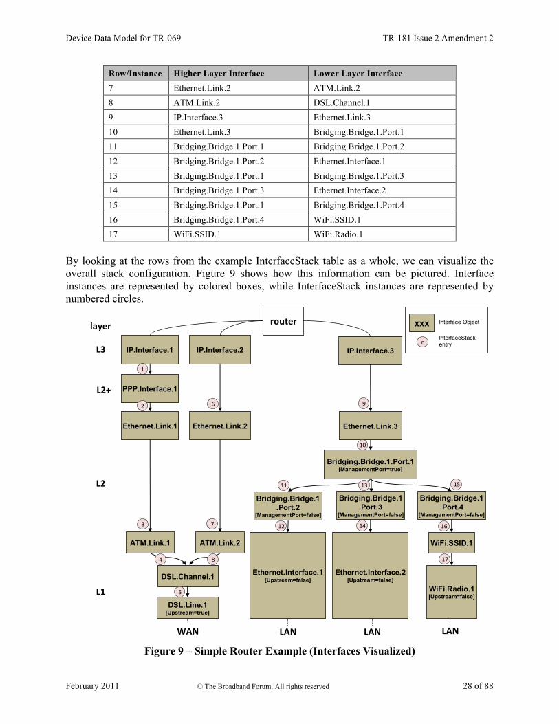
Once the CPE issues the SetParameterValuesResponse or the DeleteObjectResponse, all autonomous InterfaceStack table changes associated with the corresponding request (as described in the preceding paragraph) MUST be available for subsequent commands to operate on, regardless of whether or not these changes have been applied by the CPE (see TR-069 [2] Sections A.3.2.1 and A.3.2.7 for background on these RPC methods). As an example, Table 1 lists an InterfaceStack table configuration imagined for a fictitious, simple router. Each row in this table corresponds to a row in the InterfaceStack table. The specified objects and instance numbers are manufactured for the sake of this example; real world configurations will likely differ.
Table 1 – Simple Router Example (InterfaceStack table) Row/Instance Higher Layer Interface Lower Layer Interface 1 IP.Interface.1 PPP.Interface.1 2 PPP.Interface.1 Ethernet.Link.1 3 Ethernet.Link.1 ATM.Link.1 4 ATM.Link.1 DSL.Channel.1 5 DSL.Channel.1 DSL.Line.1 6 IP.Interface.2 Ethernet.Link.2
4 An interface instance is considered stranded when it has no lower layer references to or from other interface instances. Stranded interface instances will be omitted from the InterfaceStack table until such time as they are stacked, above or below another interface instance, via a LowerLayers parameter reference.
Device Data Model for TR-069 TR-181 Issue 2 Amendment 2
February 2011 © The Broadband Forum. All rights reserved 28 of 88
Row/Instance Higher Layer Interface Lower Layer Interface 7 Ethernet.Link.2 ATM.Link.2 8 ATM.Link.2 DSL.Channel.1 9 IP.Interface.3 Ethernet.Link.3 10 Ethernet.Link.3 Bridging.Bridge.1.Port.1 11 Bridging.Bridge.1.Port.1 Bridging.Bridge.1.Port.2 12 Bridging.Bridge.1.Port.2 Ethernet.Interface.1 13 Bridging.Bridge.1.Port.1 Bridging.Bridge.1.Port.3 14 Bridging.Bridge.1.Port.3 Ethernet.Interface.2 15 Bridging.Bridge.1.Port.1 Bridging.Bridge.1.Port.4 16 Bridging.Bridge.1.Port.4 WiFi.SSID.1 17 WiFi.SSID.1 WiFi.Radio.1
By looking at the rows from the example InterfaceStack table as a whole, we can visualize the overall stack configuration. Figure 9 shows how this information can be pictured. Interface instances are represented by colored boxes, while InterfaceStack instances are represented by numbered circles.
Bridging.Bridge.1.Port.4
[ManagementPort=false]
IP.Interface.2 IP.Interface.3
router
WAN LAN
L1
L2
L2+
L3
layer
Ethernet.Link.2
WiFi.SSID.1
IP.Interface.1
Ethernet.Link.1
PPP.Interface.1
3
8
9
Ethernet.Link.3
6
7
11
xxx Interface Object
InterfaceStack entryn
Bridging.Bridge.1.Port.1[ManagementPort=true]
LAN LAN
Bridging.Bridge.1.Port.3
[ManagementPort=false]
Bridging.Bridge.1.Port.2
[ManagementPort=false]
15
1
13
2
4 17
12 14 16
10
WiFi.Radio.1[Upstream=false]
Ethernet.Interface.2[Upstream=false]
Ethernet.Interface.1[Upstream=false]
DSL.Line.1[Upstream=true]
ATM.Link.1 ATM.Link.2
DSL.Channel.1
5
Figure 9 – Simple Router Example (Interfaces Visualized)

Device Data Model for TR-069 TR-181 Issue 2 Amendment 2
February 2011 © The Broadband Forum. All rights reserved 29 of 88
Finally, Table 2 completes the example by listing each interface instance and its corresponding LowerLayers parameter value.
Table 2 – Simple Router Example (Interface LowerLayers) Interface LowerLayers value IP.Interface.1 PPP.Interface.1 IP.Interface.2 Ethernet.Link.2 IP.Interface.3 Ethernet.Link.3 PPP.Interface.1 Ethernet.Link.1 Ethernet.Link.1 ATM.Link.1 Ethernet.Link.2 ATM.Link.2 Ethernet.Link.3 Bridging.Bridge.1.Port.1 Bridging.Bridge.1.Port.1 Bridging.Bridge.1.Port.2, Bridging.Bridge.1.Port.3, Bridging.Bridge.1.Port.4 Bridging.Bridge.1.Port.2 Ethernet.Interface.1 Bridging.Bridge.1.Port.3 Ethernet.Interface.2 Bridging.Bridge.1.Port.4 WiFi.SSID.1 ATM.Link.1 DSL.Channel.1 ATM.Link.2 DSL.Channel.1 DSL.Channel.1 DSL.Line.1 DSL.Line.1 Ethernet.Interface.1 Ethernet.Interface.2 WiFi.SSID.1 WiFi.Radio.1 WiFi.Radio.1

Device Data Model for TR-069 TR-181 Issue 2 Amendment 2
February 2011 © The Broadband Forum. All rights reserved 30 of 88
5 Parameter Definitions The normative definition of the Device:2 data model is split between several DM Instance documents (see TR-106 [3] Annex A). Table 3 lists the Device:2 data model versions and DM Instances that had been defined at the time of writing. It also indicates the corresponding Technical Reports and gives links to the associated XML and HTML files. For a given revision of the data model, the corresponding TR-181 Issue 2 XML document defines the Device:2 model itself and imports additional components from the other XML documents listed. Each TR-181 Issue 2 HTML document is a report generated from the XML files, and lists a consolidated view of the Device:2 data model in human-readable form. Note that, because new minor versions of the Device:2 data model can be defined without re-publishing this Technical Report, the table is not necessarily up-to-date. An up-to-date version of this information can always be found at http://www.broadband-forum.org/cwmp.
Table 3 – Device:2 Data Model Versions
Version DM Instance Technical Report XML and HTML5
2.0
tr-181-2-0.xml TR-181 Issue 2 http://broadband-forum.org/cwmp/tr-181-2-0.xml http://broadband-forum.org/cwmp/tr-181-2-0.html
tr-143-1-0.xml6 TR-143 http://broadband-forum.org/cwmp/tr-143-1-0.xml
tr-157-1-2.xml TR-157 Amendment 2 http://broadband-forum.org/cwmp/tr-157-1-2.xml
2.1 tr-181-2-1.xml TR-181 Issue 2
Amendment 1
http://broadband-forum.org/cwmp/tr-181-2-1.xml http://broadband-forum.org/cwmp/tr-181-2-1.html http://broadband-forum.org/cwmp/tr-181-2-1-last.html
tr-157-1-3.xml TR-157 Amendment 3 http://broadband-forum.org/cwmp/tr-157-1-3.xml
2.2 tr-181-2-2.xml TR-181 Issue 2 Amendment 2
http://broadband-forum.org/cwmp/tr-181-2-2.xml http://broadband-forum.org/cwmp/tr-181-2-2.html http://broadband-forum.org/cwmp/tr-181-2-2-last.html
5 The HTML with a name of the form tr-xxx-i-a.html, e.g. tr-181-2-1.html, lists the entire data model. The HTML with a name of the form tr-xxx-i-a-last.html, e.g. tr-181-2-1-last.html, lists only the changes since the previous version. 6 The minimum valid version of the tr-143-1-0.xml document is corrigendum 2. Earlier versions are not supported by the Device:2 data model.

Device Data Model for TR-069 TR-181 Issue 2 Amendment 2
February 2011 © The Broadband Forum. All rights reserved 31 of 88
Annex A: Bridging and Queuing
A.1 Queuing and Bridging Model Figure 10 shows the queuing and bridging model for a device. This model relates to the QoS object as well as the Bridging and Routing objects. The elements of this model are described in the following sections.
NOTE – the queuing model described in this Annex is meant strictly as a model to clarify the intended behavior of the related data objects. There is no implication intended that an implementation has to be structured to conform to this model.
.
.
.
Class 2
Class 3
Class 4
Class N
EF
AF
Class 1 Queue 1 for connection 1
Queue 2 for connection 1
Policer 1
BE Queue 3 for connection 1
Ingress Interface/ Connection
Egress Interface/ Connection Policer 2
Class X
Class Y
Class Z
Default
Classification
App protocol handler 1
Flow Type 1
Flow Type 2
Default Flow
Policer 1
Other Ingress
Interfaces
Other Non-bridgeable Egress Interfaces
Routing (Layer3Forw
arding)
Other Non-bridgeable
Ingress Interfaces
Layer2Bridging
Layer2Bridging
Other Egress Interfaces
Scheduler /S
haper
Figure 10 – Queuing Model of a Device
A.1.1 Packet Classification The Classification table within the QoS object specifies the assignment of each packet arriving at an ingress interface to a specific internal class. This classification can be based on a number of matching criteria, such as destination and source IP address, destination and source port, and protocol. Each entry in the Classification table includes a series of parameters, each indicated to be a Classification Criterion. Each classification criterion can be set to a specified value, or can be set to a value that indicates that criterion is not to be used. A packet is defined to match the classification criteria for that table entry only if the packet matches all of the specified criteria. That is, a logical AND operation is applied across all classification criteria within a given Classification table entry.

Device Data Model for TR-069 TR-181 Issue 2 Amendment 2
February 2011 © The Broadband Forum. All rights reserved 32 of 88
NOTE – to apply a logical OR to sets of classification criteria, multiple entries in the Classification table can be created that specify the same resulting queuing behavior. For each classification criterion, the Classification table also includes a corresponding “exclude” flag. This flag can be used to invert the sense of the associated classification criterion. That is, if this flag is false for a given criterion, the classifier is to include only packets that meet the specified criterion (as well as all others). If this flag is true for a given criterion, the classifier is to include all packets except those that meet the associated criterion (in addition to meeting all other criteria). For a given entry in the Classification table, the classification is to apply only to the interface specified by the Interface parameter. This parameter can specify a particular ingress interface or all sources. Depending on the particular interface, not all classification criteria will be applicable. For example, Ethernet layer classification criteria would not apply to packets arriving on a non-bridged ATM VC. Packet classification is modeled to include all ingress packets regardless of whether they ultimately will be bridged or routed through the device.
A.1.1.1 Classification Order The class assigned to a given packet corresponds to the first entry in the Classification table (given the specified order of the entries in the table) whose matching criteria match the packet. If there is no entry that matches the packet, the packet is assigned to a default class. Classification rules are sensitive to the order in which they are applied because certain traffic might meet the criteria of more than one Classification table entry. The Order parameter is responsible for identifying the order in which the Classification entries are to be applied. The following rules apply to the use and setting of the Order parameter: � Order goes in order from 1 to n, where n is equal to the number of entries in the
Classification table. 1 is the highest precedence, and n the lowest. For example, if entries with Order of 4 and 7 both have rules that match some particular traffic, the traffic will be classified according to the entry with the 4.
� The CPE is responsible for ensuring that all Order values are unique and sequential. o If an entry is added (number of entries becomes n+1), and the value specified for
Order is greater than n+1, then the CPE will set Order to n+1. o If an entry is added (number of entries becomes n+1), and the value specified for
Order is less than n+1, then the CPE will create the entry with that specified value, and increment the Order value of all existing entries with Order equal to or greater than the specified value.
o If an entry is deleted, the CPE will decrement the Order value of all remaining entries with Order greater than the value of the deleted entry.
o If the Order value of an entry is changed, then the value will also be changed for other entries greater than or equal to the lower of the old and new values, and less than the

Device Data Model for TR-069 TR-181 Issue 2 Amendment 2
February 2011 © The Broadband Forum. All rights reserved 33 of 88
larger of the old and new values. If the new value is less than the old, then these other entries will all have Order incremented. If the new value is greater than the old, then the other entries will have Order decremented and the changed entry will be given a value of <new value>-1. For example, an entry is changed from 8 to 5. The existing 5 goes to 6, 6 to 7, and 7 to 8. If the entry goes from 5 to 8, then 6 goes to 5, 7 to 6, and the changed entry is 7. This is consistent with the behavior that would occur if the change were considered to be an Add of a new entry with the new value, followed by a Delete of the entry with the old value.
A.1.1.2 Dynamic Application Specific Classification In some situations, traffic to be classified cannot be identified by a static set of classification criteria. Instead, identification of traffic flows might require explicit application awareness. The model accommodates such situations via the App and Flow tables in the QoS object. Each entry in the App table is associated with an application-specific protocol handler, identified by the ProtocolIdentifier, which contains a URN. For a particular CPE, the AvailableAppList parameter indicates which protocol handlers that CPE is capable of supporting, if any. A list of standard protocol handlers and their associated URNs is specified in Section A.3, though a CPE can also support vendor-specific protocol handlers as well. Multiple App table entries can refer to the same ProtocolIdentifier. The role of the protocol handler is to identify and classify flows based on application awareness. For example, a SIP protocol handler might identify a call-control flow, an audio flow, and a video flow. The App and Flow tables are used to specify the classification outcome associated with each such flow. For each App table entry there can be one or more associated Flow table entries. Each flow table entry identifies a type of flow associated with the protocol handler. The Type parameter is used to identify the specific type of flow associated with each entry. For example, a Flow table entry for a SIP protocol handler might refer only to the audio flows associated with that protocol handler. A list of standard flow type values is given in Section A.3, though a CPE can also support vendor-specific flow types. A protocol handler can be defined as being fed from the output of a Classification table entry. That is, a Classification entry can be used to single out control traffic to be passed to the protocol handler, which then subsequently identifies associated flows. Doing so allows more than one instance of a protocol handler associated with distinct traffic. For example, one could define two App table entries associated with SIP protocol handlers. If the classifier distinguished control traffic to feed into each handler based on the destination IP address of the SIP server, this could be used to separately classify traffic for different SIP service providers. In this case, each instance of the protocol handler would identify only those flows associated with a given service. Note that the Classification table entry that feeds each protocol handler wouldn’t encompass all of the flows; only the traffic needed by the protocol handler to determine the flows—typically only the control traffic.
Device Data Model for TR-069 TR-181 Issue 2 Amendment 2
February 2011 © The Broadband Forum. All rights reserved 34 of 88
A.1.1.3 Classification Outcome Each Classification entry specifies a tuple composed of either:
• A TrafficClass and (optionally) a Policer, or
• An App table entry Each entry also specifies:
• Outgoing DiffServ and Ethernet priority marking behavior
• A ForwardingPolicy tag that can be referenced in the Routing table to affect packet routing (note that the ForwardingPolicy tag affects only routed traffic)
Note that the information associated with the classification outcome is modeled as being carried along with each packet as it flows through the system. If a packet does not match any Classification table entry, the DefaultTrafficClass, DefaultPolicer, default markings, and default ForwardingPolicy are used. If a TrafficClass/Policer tuple is specified, classification is complete. If, however, an App is specified, the packet is passed to the protocol handler specified by the ProtocolIdentifier in the specified App table entry for additional classification (see Section A.1.1.2). If any of the identified flows match the Type specified in any Flow table entry corresponding to the given App table entry (this correspondence is indicated by the App identifier), the specified tuple and markings for that Flow table entry is used for packets in that flow. Other flows associated with the application, but not explicitly identified, use the default tuple and markings specified for that App table entry.
A.1.2 Policing The Policer table defines the policing parameters for ingress packets identified by either a Classification table entry (or the default classification) or a dynamic flow identified by a protocol handler identified in the App table. Each Policer table entry specifies the packet handling characteristics, including the rate requirements and behavior when these requirements are exceeded.
A.1.3 Queuing and Scheduling The Queue table specifies the number and types of queues, queue parameters, shaping behavior, and scheduling algorithm to use. Each Queue table entry specifies the TrafficClasses with which it is associated, and a set of egress interfaces for which a queue with the corresponding characteristics needs to exist.
NOTE – If the CPE can determine that among the interfaces specified for a queue to exist, packets classified into that queue cannot egress to a subset of those interfaces (from knowledge of the current routing and bridging configuration), the CPE can choose not to instantiate the queue on those interfaces.
NOTE – Packets classified into a queue that exit through an interface for which the queue is not specified to exist, will instead use the default queuing behavior. The default queue itself will exist on all egress interfaces.

Device Data Model for TR-069 TR-181 Issue 2 Amendment 2
February 2011 © The Broadband Forum. All rights reserved 35 of 88
The model defined here is not intended to restrict where the queuing is implemented in an actual implementation. In particular, it is up to the particular implementation to determine at what protocol layer it is most appropriate to implement the queuing behavior (IP layer, Ethernet MAC layer, ATM layer, etc.). In some cases, however, the QoS configuration would restrict the choice of layer where queueing can be implemented. For example, if a queue is specified to carry traffic that is bridged, then it could not be implemented as an IP-layer queue.
NOTE – care needs to be taken to avoid having multiple priority queues multiplexed onto a single connection that is rate shaped. In such cases, the possibility exists that high priority traffic can be held back due to rate limits of the overall connection exceeded by lower priority traffic. Where possible, each priority queue will be shaped independently using the shaping parameters in the Queue and Shaping table. The scheduling parameters defined in the Queue table apply to the first level of what might be a more general scheduling hierarchy. This specification does not specify the rules that an implementation needs to apply to determine the most appropriate scheduling hierarchy given the scheduling parameters defined in the Queue table. As an example, take a situation where the output of four distinct queues is to be multiplexed into a single connection, and two entries share one set of scheduling parameters while the other two entries share a different set of scheduling parameters. In this case, it might be appropriate to implement this as a scheduling hierarchy with the first two queues multiplexed with a scheduler defined by the first pair, and the second two queues being multiplexed with a scheduler defined by the second pair. The lower layers of this scheduling hierarchy cannot be directly determined from the content of the Queue table.
A.1.4 Bridging
NOTE – from the point of view of a bridge, packets arriving into the bridge from the local router (either upstream or downstream) are treated as ingress packets, even though the same packets, which just left the router, are treated as egress from the point of view of the router. For example, a Filter table entry might admit packets on ingress to the bridge from a particular IP interface, which means that it admits packets on their way out of the router over this layer 3 connection.
For each interface, the output of the classifier is modeled to feed a set of 802.1D [8] or 802.1Q [9] layer 2 bridges as specified by the Bridging object. Each bridge specifies layer 2 connectivity between one or more layer 2 downstream and/or upstream interfaces, and optionally one or more layer 3 connections to the local router. Each bridge corresponds to a single entry in the Bridge table of the Bridging object. The Bridge table contains the following sub-tables:
• Port table: models the Bridge ports, which are either management ports (modeling layer 3 connections to the local router) or non-management ports (modeling connections to layer 2 interfaces). Bridge ports are stackable interface objects (see Section 4.2).
• VLAN table: models the Bridge VLANs (relevant only to 802.1Q bridges).
• VLANPort table: for each VLAN, defines the ports that comprise its member set (relevant only to 802.1Q bridges).

Device Data Model for TR-069 TR-181 Issue 2 Amendment 2
February 2011 © The Broadband Forum. All rights reserved 36 of 88
A.1.4.1 Filtering Traffic from a given interface (or set of interfaces) can be selectively admitted to a given Bridge, rather than bridging all traffic from that interface. Each entry in the Filter table includes a series of classification criteria. Each classification criterion can be set to a specified value, or can be set to a value that indicates that criterion is not to be used. A packet is admitted to the Bridge only if the packet matches all of the specified criteria. That is, a logical AND operation is applied across all classification criteria within a given Filter table entry.
NOTE – to apply a logical OR to sets of classification criteria, multiple entries in the Filter table can be created that refer to the same interfaces and the same Bridge table entry.
NOTE – a consequence of the above rule is that, if a packet does not match the criteria of any of the enabled Filter table entries, then it will not be admitted to any bridges, i.e. it will be dropped. As a specific example of this, if none of the enabled Filter table entries reference a given interface, then all packets arriving on that interface will be dropped. For each classification criterion, the Filter table also includes a corresponding “exclude” flag. This flag can be used to invert the sense of the associated classification criterion. That is, if this flag is false for a given criterion, the Bridge will admit only packets that meet the specified criterion (as well as all other criteria). If this flag is true for a given criterion, the Bridge will admit all packets except those that meet the associated criterion (in addition to meeting all other criteria). Note that because the classification criteria are based on layer 2 packet information, if the selected port for a given Filter table entry is a layer 3 connection from the local router, the layer 2 classification criteria do not apply.
A.1.4.2 Filter Order Any packet that matches the filter criteria of one or more filters is admitted to the Bridge associated with the first entry in the Filter table (relative to the specified Order). The following rules apply to the use and setting of the Order parameter: � The Order goes in order from 1 to n, where n is equal to the number of filters. 1 is the highest
precedence, and n the lowest. � The CPE is responsible for ensuring that all Order values among filters are unique and
sequential. o If a filter is added (number of filters becomes n+1), and the value specified for Order
is greater than n+1, then the CPE will set Order to n+1. o If a filter is added (number of entries becomes n+1, and the value specified for Order
is less than n+1, then the CPE will create the entry with that specified value, and increment the Order value of all existing filters with Order equal to or greater than the specified value.
o If a filter is deleted, the CPE will decrement the Order value of all remaining filters with Order greater than the value of the deleted entry.

Device Data Model for TR-069 TR-181 Issue 2 Amendment 2
February 2011 © The Broadband Forum. All rights reserved 37 of 88
o If the Order value of a filter is changed, then the value will also be changed for other filters greater than or equal to the lower of the old and new values, and less than the larger of the old and new values. If the new value is less than the old, then these other entries will all have Order incremented. If the new value is greater than the old, then the other entries will have Order decremented and the changed entry will be given a value of <new value>-1. For example, an entry is changed from 8 to 5. The existing 5 goes to 6, 6 to 7, and 7 to 8. If the entry goes from 5 to 8, then 6 goes to 5, 7 to 6, and the changed entry is 7. This is consistent with the behavior that would occur if the change were considered to be an Add of a new filter with the new value, followed by a Delete of the filter with the old value.
A.2 Default Layer 2/3 QoS Mapping Table 4 presents a “default” mapping between layer 2 and layer 3 QoS. In practice, it is a guideline for automatic marking of DSCP (layer 3) based upon Ethernet Priority (layer 2) and the other way around. Please refer to the QoS Classification table’s DSCPMark and EthernetPriorityMark parameters (and related parameters) for configuration of a default automatic DSCP / Ethernet Priority mapping. Automatic marking of DSCP or Ethernet Priority is likely only in the following cases:
• WAN à LAN: to map DSCP (layer 3) to Ethernet Priority (layer 2)
• LAN à WAN: to map Ethernet Priority (layer 2) to DSCP (layer 3) Automatic marking in the LAN à LAN case is unlikely, since LAN QoS is likely to be supported only at layer 2, and LAN DSCP values, if used, will probably be a direct representation of Ethernet Priority, e.g. Ethernet Priority shifted left by three bits. In the table, grayed and bolded items are added to allow two-way mapping between layer 2 and layer 3 QoS (where the mapping is ambiguous, the grayed values SHOULD be ignored and the bolded values SHOULD be used). If, when mapping from layer 3 to layer 2 QoS, the DSCP value is not present in the table, the mapping SHOULD be based only on the first three bits of the DSCP value, i.e. on DSCP & 111000.
Table 4 – Default Layer 2/3 QoS Mapping Layer 2 Layer 3
Ethernet Priority Designation DSCP Per Hop Behavior
001 (1) BK 000000 (0x00) Default
010 (2) spare 000000 (0x00)
000 (0) BE 000000 (0x00) 000000 (0x00)
Default CS0
011 (3) EE
001110 (0x0e) 001100 (0x0c) 001010 (0x0a) 001000 (0x08)
AF13 AF12 AF11 CS1
100 (4) CL
010110 (0x16) 010100 (0x14) 010010 (0x12) 010000 (0x10)
AF23 AF22 AF21 CS2

Device Data Model for TR-069 TR-181 Issue 2 Amendment 2
February 2011 © The Broadband Forum. All rights reserved 38 of 88
101 (5) VI
011110 (0x1e) 011100 (0x1c) 011010 (0x1a) 011000 (0x18)
AF33 AF32 AF31 CS3
110 (6) VO
100110 (0x26) 100100 (0x24) 100010 (0x22) 100000 (0x20)
AF43 AF42 AF41 CS4
110 (6) VO 101110 (0x2e) 101000 (0x28)
EF CS5
111 (7) NC 110000 (0x30) 111000 (0x38)
CS6 CS7
A.3 URN Definitions for App and Flow Tables
A.3.1 App ProtocolIdentifier Table 5 lists the URNs defined for the QoS App table’s ProtocolIdentifier parameter. Additional standard or vendor-specific URNs can be defined following the standard syntax for forming URNs.
Table 5 – ProtocolIdentifer URNs URN Description urn:dslforum-org:sip Session Initiation Protocol (SIP) as defined by RFC 3261 [12]
urn:dslforum-org:h.323 ITU-T Recommendation H.323
urn:dslforum-org:h.248 ITU-T Recommendation H.248 (MEGACO)
urn:dslforum-org:mgcp Media Gateway Control Protocol (MGCP) as defined by RFC 3435 [13]
urn:dslforum-org:pppoe Bridged sessions of PPPoE
A.3.2 Flow Type A syntax for forming URNs for the QoS Flow table’s Type parameter is defined for the Session Description Protocol (SDP) as defined by RFC 4566 [14]. Additional standard or vendor-specific URNs can be defined following the standard syntax for forming URNs. A URN to specify an SDP flow is formed as follows:
urn:dslforum-org:sdp-[MediaType]-[Transport] [MediaType] corresponds to the “media” sub-field of the “m” field of an SDP session description. [Transport] corresponds to the “transport” sub-field of the “m” field of an SDP session description. Non-alphanumeric characters in either field are removed (e.g., “rtp/avp” becomes “rtpavp”). For example, the following would be valid URNs referring to SDP flows:
urn:dslforum-org:sdp-audio-rtpavp urn:dslforum-org:sdp-video-rtpavp urn:dslforum-org:sdp-data-udp
For flow type URNs following this convention, there is no defined use for TypeParameters, which SHOULD be left empty.

Device Data Model for TR-069 TR-181 Issue 2 Amendment 2
February 2011 © The Broadband Forum. All rights reserved 39 of 88
For the ProtocolIdentifier urn:dslforum-org:pppoe, a single flow type is defined referring to the entire PPPoE session. The URL for this flow type is:
urn:dslforum-org:pppoe
A.3.3 Flow TypeParameters For the flow type urn:dslforum-org:pppoe, Table 6 specifies the defined TypeParameter values.
Table 6 – Flow TypeParameters values for flow type urn:dslforum-org:pppoe Name Description of Value ServiceName The PPPoE service name.
If specified, only bridged PPPoE sessions designated for the named service would be considered part of this flow. If this parameter is not specified, or is empty, bridged PPPoE associated with any service considered part of this flow.
ACName The PPPoE access concentrator name. If specified, only bridged PPPoE sessions designated for the named access concentrator would be considered part of this flow. If this parameter is not specified, or is empty, bridged PPPoE associated with any access concentrator considered part of this flow.
PPPDomain The domain part of the PPP username. If specified, only bridged PPPoE sessions in which the domain portion of the PPP username matches this value are considered part of this flow. If this parameter is not specified, or is empty, all bridged PPPoE sessions are considered part of this flow.

Device Data Model for TR-069 TR-181 Issue 2 Amendment 2
February 2011 © The Broadband Forum. All rights reserved 40 of 88
Appendix I: Example RG Queuing Architecture (from TR-059)
The queuing and scheduling discipline envisioned upstream for the RG is shown in Figure 11. There are multiple access sessions supported in this model, however, all traffic is classified and scheduled in a monolithic system. So, while it might appear at first that the Diffserv queuing and scheduling might apply only to IP-aware access – in fact all access, IP, Ethernet, or PPP is managed by the same system that adheres to the Diffserv model. For example, at the bottom of the figure, BE treatment is given to the non-IP-aware access sessions (PPPoE started behind the RG or delivered to an L2TP tunnel delivery model). This queue might be repeated several times in order to support fairness among multiple PPPoE accesses – or it can be a monolithic queue with separate rate limiters applied to the various access sessions. The PTA access is a single block of queues. This is done because NSP access typically works with a single default route to the NSP, and managing more than one simultaneously at the RG would be perilous. The ∑ rate limiter would limit the overall access traffic for a service provider. Rate limiters are also shown within the EF and AF service classes because the definition of those Diffserv types is based on treating the traffic differently when it falls into various rates. Finally, at the top of the diagram is the ASP access block of queues. In phase 1A, these queues are provisioned and provide aggregate treatment of traffic mapped to them. In phase 1B, it will become possible to assign AF queues to applications to give them specific treatment instead of aggregate treatment. The EF service class can also require a high degree of coordination among the applications that make use of it so that its maximum value is not exceeded. Notable in this architecture is that all the outputs of the EF, AF, and BE queues are sent to a scheduler (S) that pulls traffic from them in a strict priority fashion. In this configuration EF traffic is, obviously, given highest precedence and BE is given the lowest. The AF service classes fall in-between. Note that there is significant interest in being able to provide a service arrangement that would allow general Internet access to have priority over other (bulk rate) services.7 Such an arrangement would be accomplished by assigning the bulk rate service class to BE and by assigning the default service class (Internet access) as AF with little or no committed information rate. Given this arrangement, the precedence of traffic shown in the figure is arranged as:
1. EF – red dotted line 7 This “bulk rate” service class would typically be used for background downloads and potentially for peer-to-peer applications as an alternative to blocking them entirely.

Device Data Model for TR-069 TR-181 Issue 2 Amendment 2
February 2011 © The Broadband Forum. All rights reserved 41 of 88
2. AF – blue dashed line (with various precedence among AF classes as described in RFC 2597 [10])
3. BE – black solid line
Data In
Data Out
Classifier
PPP Access (BE or AF)
EF
PTA Access
(es)
BE
AF1
ASP Access
S
AF2
AF4
AF3
EF
BE
AF1
AF2
AF4
AF3
RL
RL
RL
∑RL
as per RFC 2597
as per RFC 2598
RL
RL
Data In
Data Out
Classifier
PPP Access (BE or AF)
EF
PTA Access
(es)
BE
AF1
ASP Access
S
AF2
AF4
AF3
EF
BE
AF1
AF2
AF4
AF3
RL
RL
RL
∑RL
as per RFC 2597
as per RFC 2598
RL
RL
Figure 11 – Queuing and Scheduling Example for RG
In Figure 11 the following abbreviations apply:
ASP – Application Service Provider PTA – PPP Terminated Aggregation PPP – Point-to-Point Protocol EF – Expedited Forwarding – as defined in RFC 3246 [11] AF – Assured Forwarding – as defined in RFC 2597 [10] BE – Best Effort forwarding RL – Rate Limiter ∑RL – Summing Rate Limiter (limits multiple flows) S – Scheduler

Device Data Model for TR-069 TR-181 Issue 2 Amendment 2
February 2011 © The Broadband Forum. All rights reserved 42 of 88
Appendix II: Use of Bridging Objects for VLAN Tagging In the case of an Ethernet upstream Interface or a VDSL2 upstream Interface based on PTM-EFM, 802.1Q Tagging can be used to tag egress traffic. This choice enables a multi-VLAN architecture in order to deploy a multi-service configuration (high speed Internet, VoIP, Video Phone, IPTV, etc.), where one VLAN or a group of VLANs are associated with each service. If 802.1Q tagging on the upstream interface is used, it is necessary to have a way to associate incoming upstream 802.1Q tagged or untagged traffic or internally generated traffic (PPPoE, IPoE connections) to the egress (and vice-versa). The solution is to apply coherent bridging rules. Regarding different traffic bridging rules, the possible cases are characterized as follows:
• Tagged LAN to tagged WAN traffic (pure VLAN bridging), with VLAN ID translation as a special case
• Untagged LAN to tagged WAN traffic • Internally generated to tagged WAN traffic
To better understand the different cases, refer to Figure 12 and to the following examples.
WAN
Eth # 1
Eth # 2
VoI P
Phone
Video
Phone
STBEth # 3
VLANID = x
VLANID = y
VLANID = x
VLANID = z
VLANID = k No VLANID
PPPoE
VLANID = jVLAN Termination # 1
Bridge # 3
Bridge # 1
LAN
Bridge # 2
WAN
Eth # 1
Eth # 2
VoI P
Phone
Video
Phone
STBEth # 3
VLANID = x
VLANID = y
VLANID = x
VLANID = z
VLANID = k No VLANID
PPPoE
VLANID = jVLAN Termination # 1
Bridge # 3
Bridge # 1
LAN
Bridge # 2
Figure 12 – Examples of VLAN configuration based on Bridging and VLAN Termination
objects
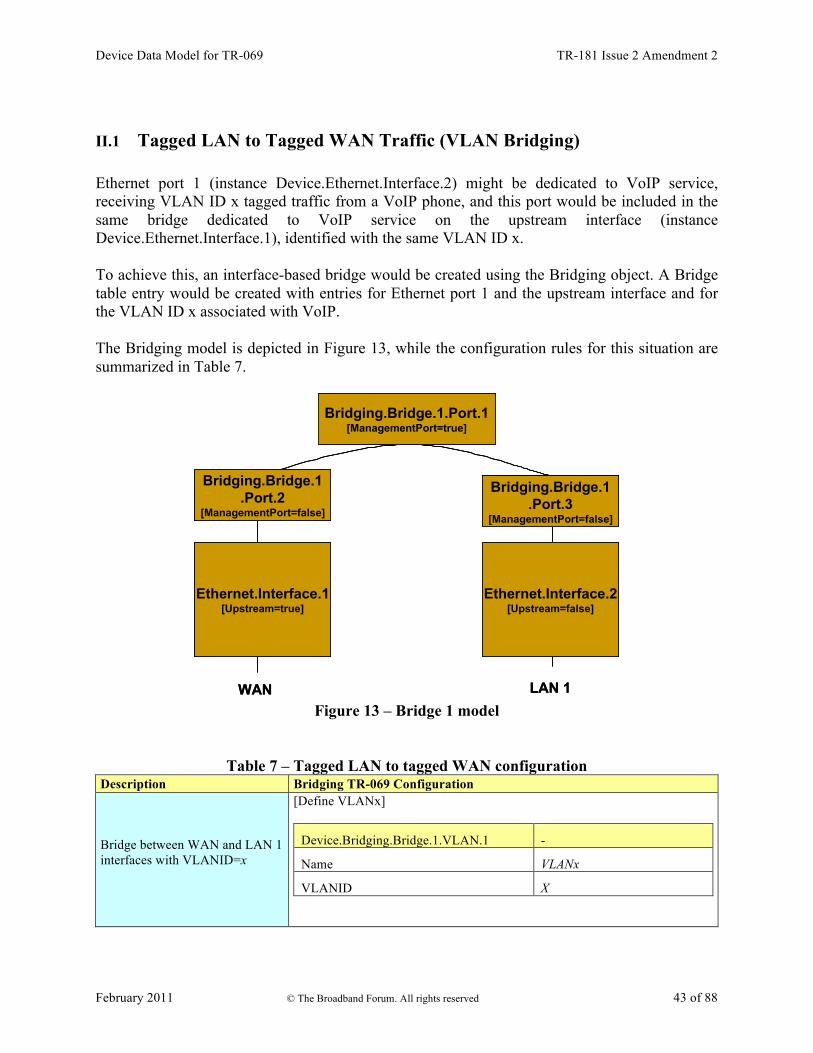
Device Data Model for TR-069 TR-181 Issue 2 Amendment 2
February 2011 © The Broadband Forum. All rights reserved 43 of 88
II.1 Tagged LAN to Tagged WAN Traffic (VLAN Bridging) Ethernet port 1 (instance Device.Ethernet.Interface.2) might be dedicated to VoIP service, receiving VLAN ID x tagged traffic from a VoIP phone, and this port would be included in the same bridge dedicated to VoIP service on the upstream interface (instance Device.Ethernet.Interface.1), identified with the same VLAN ID x. To achieve this, an interface-based bridge would be created using the Bridging object. A Bridge table entry would be created with entries for Ethernet port 1 and the upstream interface and for the VLAN ID x associated with VoIP. The Bridging model is depicted in Figure 13, while the configuration rules for this situation are summarized in Table 7.
WAN LAN 1
Bridging.Bridge.1.Port.1[ManagementPort=true]
Bridging.Bridge.1.Port.2
[ManagementPort=false]
Ethernet.Interface.2[Upstream=false]
Ethernet.Interface.1[Upstream=true]
Bridging.Bridge.1.Port.3
[ManagementPort=false]
WAN LAN 1
Bridging.Bridge.1.Port.1[ManagementPort=true]
Bridging.Bridge.1.Port.2
[ManagementPort=false]
Ethernet.Interface.2[Upstream=false]
Ethernet.Interface.1[Upstream=true]
Bridging.Bridge.1.Port.3
[ManagementPort=false]
Bridging.Bridge.1.Port.1[ManagementPort=true]
Bridging.Bridge.1.Port.2
[ManagementPort=false]
Ethernet.Interface.2[Upstream=false]
Ethernet.Interface.1[Upstream=true]
Bridging.Bridge.1.Port.3
[ManagementPort=false]
Figure 13 – Bridge 1 model
Table 7 – Tagged LAN to tagged WAN configuration Description Bridging TR-069 Configuration
Bridge between WAN and LAN 1 interfaces with VLANID=x
[Define VLANx]
Device.Bridging.Bridge.1.VLAN.1 -
Name VLANx
VLANID X
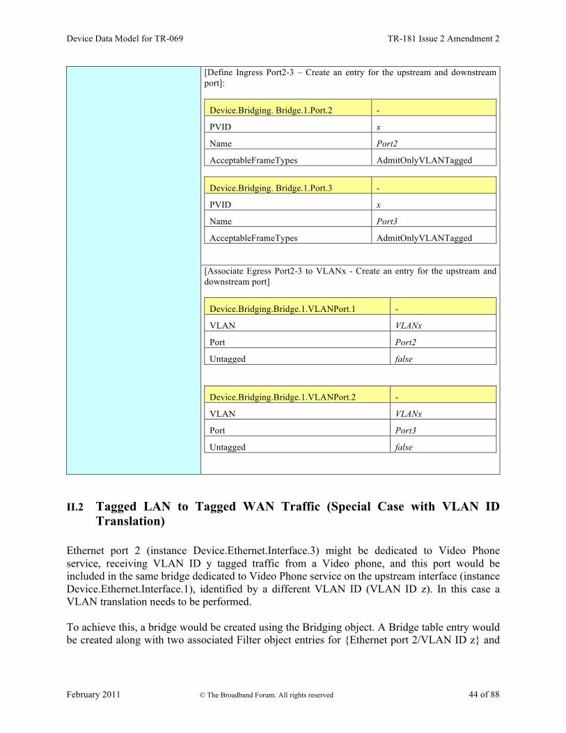
Device Data Model for TR-069 TR-181 Issue 2 Amendment 2
February 2011 © The Broadband Forum. All rights reserved 44 of 88
[Define Ingress Port2-3 – Create an entry for the upstream and downstream port]:
Device.Bridging. Bridge.1.Port.2 -
PVID x
Name Port2
AcceptableFrameTypes AdmitOnlyVLANTagged
Device.Bridging. Bridge.1.Port.3 -
PVID x
Name Port3
AcceptableFrameTypes AdmitOnlyVLANTagged [Associate Egress Port2-3 to VLANx - Create an entry for the upstream and downstream port]
Device.Bridging.Bridge.1.VLANPort.1 -
VLAN VLANx
Port Port2
Untagged false
Device.Bridging.Bridge.1.VLANPort.2 -
VLAN VLANx
Port Port3
Untagged false
II.2 Tagged LAN to Tagged WAN Traffic (Special Case with VLAN ID Translation)
Ethernet port 2 (instance Device.Ethernet.Interface.3) might be dedicated to Video Phone service, receiving VLAN ID y tagged traffic from a Video phone, and this port would be included in the same bridge dedicated to Video Phone service on the upstream interface (instance Device.Ethernet.Interface.1), identified by a different VLAN ID (VLAN ID z). In this case a VLAN translation needs to be performed. To achieve this, a bridge would be created using the Bridging object. A Bridge table entry would be created along with two associated Filter object entries for {Ethernet port 2/VLAN ID z} and

Device Data Model for TR-069 TR-181 Issue 2 Amendment 2
February 2011 © The Broadband Forum. All rights reserved 45 of 88
{upstream interface/VLAN ID y}. The Filter identifies the ingress interface and causes the ingress frames to be bridged to the egress VLAN, permitting VLAN-ID translation. The Bridging model is depicted in Figure 14, while the configuration rules for this situation are summarized in Table 8.
Bridging.Bridge.2.Port.1[ManagementPort=true]
Bridging.Bridge.2.Port.2
[ManagementPort=false]
Ethernet.Interface.3[Upstream=false]
Ethernet.Interface.1[Upstream=true]
WAN LAN 2
Bridging.Bridge.2.Port.3
[ManagementPort=false]
Bridging.Bridge.2.Port.1[ManagementPort=true]
Bridging.Bridge.2.Port.2
[ManagementPort=false]
Ethernet.Interface.3[Upstream=false]
Ethernet.Interface.1[Upstream=true]
WAN LAN 2
Bridging.Bridge.2.Port.3
[ManagementPort=false]
Figure 14 – Bridge 2 model
Table 8 – Tagged LAN to tagged WAN configuration (VLAN ID translation) Description Bridging TR-069 Configuration
Tagged LAN 2 to tagged WAN traffic (and vice versa) (special case with VLAN ID translation) upstream VLAN-ID=z downstream VLAN-ID=y
[Define VLANy and VLANz]
Device.Bridging.Bridge.2.VLAN.1
Name VLANy
VLANID y
Device.Bridging.Bridge.2.VLAN.2
Name VLANz
VLANID z

Device Data Model for TR-069 TR-181 Issue 2 Amendment 2
February 2011 © The Broadband Forum. All rights reserved 46 of 88
[Define Ingress Port2 – Create an entry for upstream port]:
Device.Bridging.Bridge.2.Port.2
PVID Z
Name Port2
AcceptableFrameTypes AdmitOnlyVLANTagged [Define Ingress Port3 – Create an entry for the downstream port]:
Device.Bridging.Bridge.2.Port.3
PVID y
Name Port3
AcceptableFrameTypes AdmitOnlyVLANTagged [Associate Egress Port2 to VLANz - Create an entry for upstream port]
Device.Bridging.Bridge.2.VLANPort.1 -
VLAN VLANz
Port Port2
Untagged false [Associate Egress Port3 to VLANy - Create an entry for each downstream port]
Device.Bridging.Bridge.2.VLANPort.2 -
VLAN VLANy
Port Port3
Untagged false [Define filter on upstream: ingress from Port 2 is associated with VLANy]
Device.Bridging.Filter.1. -
Bridge VLANy
Interface Port2 [Define filter on downstream: ingress from Port 3 is associated with VLANz]
Device.Bridging.Filter.2. -
Bridge VLANz
Interface Port3

Device Data Model for TR-069 TR-181 Issue 2 Amendment 2
February 2011 © The Broadband Forum. All rights reserved 47 of 88
II.3 Untagged LAN to Tagged WAN Traffic Ethernet port 3 (instance Device.Ethernet.Interface.4) might be dedicated to IPTV service, receiving untagged traffic from a STB, and this port would be included in the same bridge dedicated to IPTV service on the upstream interface (instance Device.Ethernet.Interface.1), identified with the VLAN ID k. To achieve this, an interface-based bridge would be created using the Bridging object. A Bridge table entry would be created, associating in the same bridge untagged frames on Ethernet port 3 with tagged frames on the upstream interface. The Bridging model is depicted in Figure 15, while the configuration rules for this situation are summarized in Table 9.
Bridging.Bridge.3.Port.1[ManagementPort=true]
Bridging.Bridge.3.Port.2
[ManagementPort=false]
Ethernet.Interface.4[Upstream=false]
Ethernet.Interface.1[Upstream=true]
WAN LAN 3
Bridging.Bridge.3.Port.3
[ManagementPort=false]
Bridging.Bridge.3.Port.1[ManagementPort=true]
Bridging.Bridge.3.Port.2
[ManagementPort=false]
Ethernet.Interface.4[Upstream=false]
Ethernet.Interface.1[Upstream=true]
WAN LAN 3
Bridging.Bridge.3.Port.3
[ManagementPort=false]
Figure 15 – Bridge 3 model
Table 9 – Untagged LAN to tagged WAN configuration Description Bridging TR-069 Configuration
Untagged LAN 3 to tagged WAN (VLAN-ID=k) traffic
[Define VLANk]
Device.Bridging.Bridge.3.VLAN.1
Name VLANk
VLANID k

Device Data Model for TR-069 TR-181 Issue 2 Amendment 2
February 2011 © The Broadband Forum. All rights reserved 48 of 88
[Define Ingress Port2 – Create an entry for upstream port]:
Device.Bridging.Bridge.3.Port.2
PVID k
Name Port2
AcceptableFrameTypes AdmitOnlyVLANTagged [Define Ingress Port3 – Create an entry for the downstream port]:
Device.Bridging.Bridge.3.Port.3
Name Port3
AcceptableFrameTypes AdmitAll [Associate Egress Port2 to VLANk - Create an entry for upstream port]
Device.Bridging.Bridge.3.VLANPort.1 -
VLAN VLANk
Port Port2
Untagged false [Associate Egress Port3 to VLANk - Create an entry for each downstream port]
Device.Bridging.Bridge.3.VLANPort.2 -
VLAN VLANk
Port Port3
Untagged true
II.4 Internally Generated to Tagged WAN Traffic A CPE PPPoE internal session (instance Device.PPP.Interface.1) might be dedicated to Management service and this logical interface would encapsulate/de-encapsulate its outgoing or incoming traffic in the VLAN ID j, dedicated to Management service. To achieve this, instead of using a bridging object, a VLAN Termination interface would be created (Device.Ethernet.VLANTermination.1). The Bridging model is depicted in Figure 16, while the configuration rules for this situation are summarized in Table 10.

Device Data Model for TR-069 TR-181 Issue 2 Amendment 2
February 2011 © The Broadband Forum. All rights reserved 49 of 88
Ethernet.Link.1
device
Ethernet.VLANTermination.1
Ethernet.Interface.1[Upstream=true]
IP.Interface.1
WAN
PPP.Interface.1
Ethernet.Link.1
device
Ethernet.VLANTermination.1
Ethernet.Interface.1[Upstream=true]
IP.Interface.1
WAN
PPP.Interface.1
Figure 16 – VLAN Termination model
Table 10 – Internally generated to tagged WAN configuration Description VLAN Termination TR-069 Configuration
[DefineVLAN Termination on top of Ethernet Link]
Device.Ethernet.VLANTermination.1
VLANID j
LowerLayers Ethernet.Link.1
II.5 Other Issues The previous rules can be applied to allow all combinations of traffic. If the subscriber’s services are modified, the Bridging configuration might need to be modified accordingly. It can be interesting to detail the configuration of three special cases:
• More than one downstream interface in a bridge • 802.1D (re-)marking • More than one VLAN ID tag for the same downstream interface

Device Data Model for TR-069 TR-181 Issue 2 Amendment 2
February 2011 © The Broadband Forum. All rights reserved 50 of 88
II.5.1 More than one Downstream Interface in a Bridge Referring to the example in Section II.1, Tagged LAN to tagged WAN traffic (VLAN bridging), consider adding other Ethernet interfaces (e.g. Ethernet ports 3 and 4 = instance Device. Ethernet.Interface.3/4) to the Video Phone service. The behavior is the same as for the existing Ethernet port 2 (instance Device.Ethernet.Interface.2). To achieve this, new entries need to be added for interface Eth-3 and Eth-4. The Bridging model is depicted in Figure 17, while the configuration rules for this situation are summarized in Table 7 and Table 11.
Bridging.Bridge.1.Port.1[ManagementPort=true]
Bridging.Bridge.1.Port.2
[ManagementPort=false]
Ethernet.Interface.2[Upstream=false]
Ethernet.Interface.1[Upstream=true]
Ethernet.Interface.3[Upstream=false]
WAN LAN 1 LAN 2
Bridging.Bridge.1.Port.3
[ManagementPort=false]
Bridging.Bridge.1.Port.4
[ManagementPort=false]
Ethernet.Interface.4[Upstream=false]
LAN 3
Bridging.Bridge.1.Port.5
[ManagementPort=false]
Figure 17 – Bridge 1 model
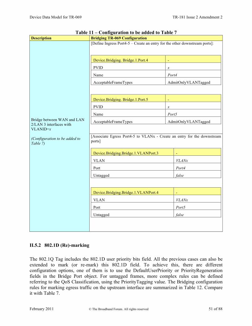
Device Data Model for TR-069 TR-181 Issue 2 Amendment 2
February 2011 © The Broadband Forum. All rights reserved 51 of 88
Table 11 – Configuration to be added to Table 7 Description Bridging TR-069 Configuration
Bridge between WAN and LAN 2/LAN 3 interfaces with VLANID=x (Configuration to be added to Table 7)
[Define Ingress Port4-5 – Create an entry for the other downstream ports]:
Device.Bridging. Bridge.1.Port.4 -
PVID x
Name Port4
AcceptableFrameTypes AdmitOnlyVLANTagged
Device.Bridging. Bridge.1.Port.5 -
PVID x
Name Port5
AcceptableFrameTypes AdmitOnlyVLANTagged [Associate Egress Port4-5 to VLANx - Create an entry for the downstream ports]
Device.Bridging.Bridge.1.VLANPort.3 -
VLAN VLANx
Port Port4
Untagged false
Device.Bridging.Bridge.1.VLANPort.4 -
VLAN VLANx
Port Port5
Untagged false
II.5.2 802.1D (Re)-marking The 802.1Q Tag includes the 802.1D user priority bits field. All the previous cases can also be extended to mark (or re-mark) this 802.1D field. To achieve this, there are different configuration options, one of them is to use the DefaultUserPriority or PriorityRegeneration fields in the Bridge Port object. For untagged frames, more complex rules can be defined referring to the QoS Classification, using the PriorityTagging value. The Bridging configuration rules for marking egress traffic on the upstream interface are summarized in Table 12. Compare it with Table 7.

Device Data Model for TR-069 TR-181 Issue 2 Amendment 2
February 2011 © The Broadband Forum. All rights reserved 52 of 88
Table 12 – 802.1D (re-)marking
Description Bridging TR-069 Configuration
802.1D (re-)marking Remark all WAN egress traffic
[Mark the ingress frames with Default user Priority, in this case 0]
Device.Bridging. Bridge.1. Port.2.
DefaultUserPriority 0 [Remark each ingress priority value (0,1,2,3,4,5,6,7) with the priority regeneration string, in this case (0,0,0,0,4,4,4,4)]
Device.Bridging. Bridge.1. Port.2.
PriorityRegeneration 0,0,0,0,4,4,4,4 [In case of ingress untagged frames, for more complex classification, QoS object are referred. In this case remark with 0]
Device.Bridging. Bridge.1. Port.2.
PriorityTagging true
Device.QoS. Classification. {i}.
EthernetPriorityMark 0
II.5.3 More than one VLAN ID Tag Admitted on the Same Downstream Interface Another scenario that can be further detailed is the case of more than one VLAN ID tag admitted on the same downstream interface. A practical example would be a 2 box scenario, with a User Device generating traffic segregated in multiple VLANs (e.g. a router offering services to the customer), and a Residential Gateway, providing upstream connectivity to the Access Network, with the connection between the two pieces of equipment using an Ethernet interface. In this case, we assume the User Device is able to tag the different traffic flows, segregating the different services (Voice, Video, …) into different VLANs. The Residential Gateway needs, on the same downstream interface, to be able to receive different VLAN ID and correctly forward or translate to the upstream interface (and vice versa). To achieve this, appropriate Bridging objects need to be configured.

Device Data Model for TR-069 TR-181 Issue 2 Amendment 2
February 2011 © The Broadband Forum. All rights reserved 53 of 88
WAN
Eth # 1 User
Device
VLANID = x
VLANID = y
VLANID = x
VLANID = y
VLANID = k
Bridge # 2
Bridge # 1
LAN
VLANID = zBridge # 3
WAN
Eth # 1 User
Device
VLANID = x
VLANID = y
VLANID = x
VLANID = y
VLANID = k
Bridge # 2
Bridge # 1
LAN
VLANID = zBridge # 3
Figure 18 – Example of VLAN configuration in a 2 box scenario
Referring to Figure 18 as an example, assume the case of three VLANs (VLAN ID=x,y,z) offered by a User Device to the Residential Gateway on the same downstream interface (Eth #1). The Residential Gateway bridges two of them (VLAN ID=x,y) and translates the other one (VLAN ID=z) to the upstream interface (VLAN ID=k). On the Residential Gateway, this can be achieved using a combination of the Bridging objects detailed in the preceding sections, with 3 bridge entries and their related entries. Refer to Figure 19 for the Bridging model and Table 13 for the global configuration.
Bridging.Bridge.2.Port.1[ManagementPort=true]
Bridging.Bridge.2.Port.2
[ManagementPort=false]
Ethernet.Interface.2[Upstream=false]
Ethernet.Interface.1[Upstream=true]
WAN LAN 1
Bridging.Bridge.2.Port.3
[ManagementPort=false]
Bridging.Bridge.1.Port.1[ManagementPort=true]
Bridging.Bridge.1.Port.2
[ManagementPort=false]
Bridging.Bridge.1.Port.3
[ManagementPort=false]
Bridging.Bridge.3.Port.1[ManagementPort=true]
Bridging.Bridge.3.Port.2
[ManagementPort=false]
Bridging.Bridge.3.Port.3
[ManagementPort=false]
Figure 19 – Bridge 1,2,3 model
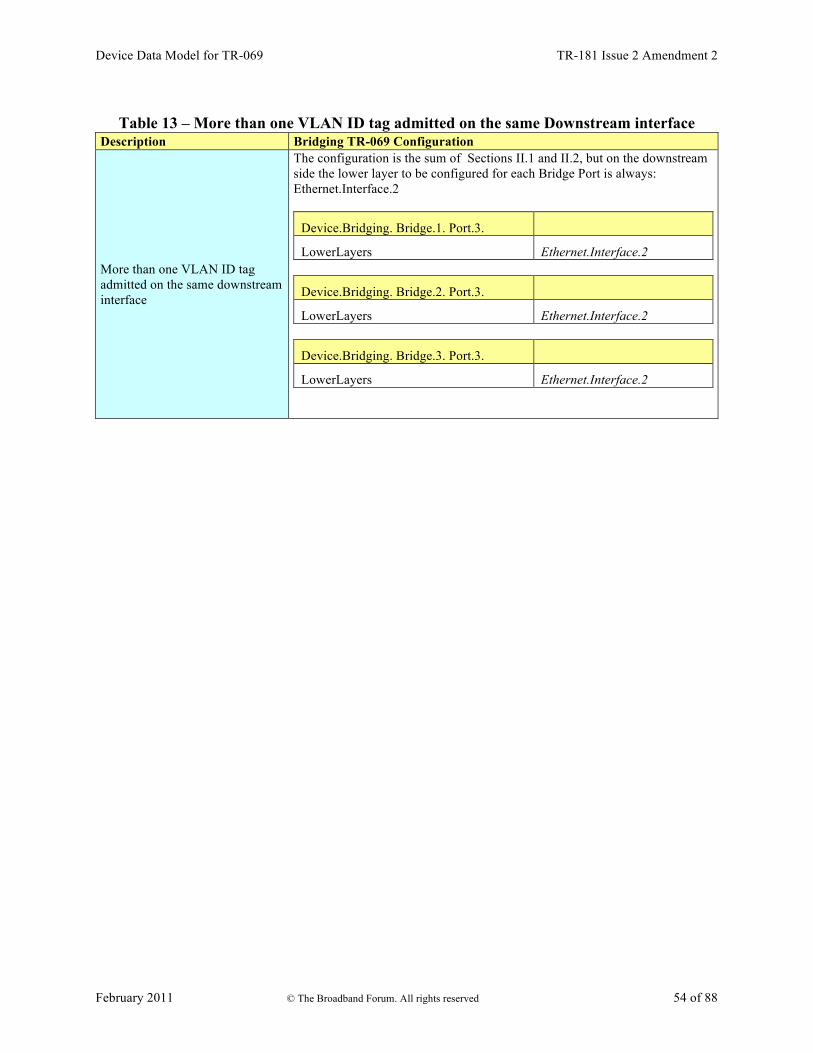
Device Data Model for TR-069 TR-181 Issue 2 Amendment 2
February 2011 © The Broadband Forum. All rights reserved 54 of 88
Table 13 – More than one VLAN ID tag admitted on the same Downstream interface
Description Bridging TR-069 Configuration
More than one VLAN ID tag admitted on the same downstream interface
The configuration is the sum of Sections II.1 and II.2, but on the downstream side the lower layer to be configured for each Bridge Port is always: Ethernet.Interface.2
Device.Bridging. Bridge.1. Port.3.
LowerLayers Ethernet.Interface.2
Device.Bridging. Bridge.2. Port.3.
LowerLayers Ethernet.Interface.2
Device.Bridging. Bridge.3. Port.3.
LowerLayers Ethernet.Interface.2

Device Data Model for TR-069 TR-181 Issue 2 Amendment 2
February 2011 © The Broadband Forum. All rights reserved 55 of 88
Appendix III: Wi-Fi Theory of Operation This section discusses the theory of operations for various technologies found within the Device:2 data model.
III.1 Multi-radio and Multi-band Wi-Fi Radio Devices The WiFi.Radio object description says “This object models an 802.11 wireless radio on a device. If the device can establish more than one connection simultaneously (e.g. a dual radio device), a separate WiFi.Radio instance will be used for each physical radio of the device.” The following sections clarify when multiple WiFi.Radio instances are needed, and the impact on their underlying parameters in the case of multi-radio and/or multi-band devices.
III.2 Definitions Each physical radio allows the transmission and reception of data on a single Wi-Fi channel at a given time. A single-radio device is able to transmit/receive a packet at a given time only on one Wi-Fi channel. Similarly, a dual-radio device is able to simultaneously transmit/receive data on two Wi-Fi channels. In general, a device with N radios is able to simultaneously transmit/receive data on N Wi-Fi channels. An important point is that Wi-Fi can operate at two different frequency bands, 2.4 GHz and 5 GHz, as follows:
• Wi-Fi technologies based on IEEE 802.11b/g standard operate on the 2.4 GHz frequency band.
• Wi-Fi technologies based on IEEE 802.11a standard operate on the 5 GHz frequency band.
• Wi-Fi technologies based on IEEE 802.11n standard operate on both the 2.4 and 5 GHz frequency bands.
Radios that operate at a single frequency band (e.g. 2.4 GHz only 802.11b/g devices) are called single-band radios. Radios that can operate at both 2.4 and 5 GHz frequency bands (e.g. 802.11a/b/g devices) are called dual-band radios. A dual-band device can be a single-radio device if it can be configured to operate at 2.4 or 5 GHz frequency bands. However, only a single frequency band is used to transmit/receive at a given time. In such a case the device has a single physical radio that is dual-band. Also, a dual-radio single-band device can exist (although uncommon) if both radios are single-band.
III.3 Number of Instances of WiFi.Radio Object Given the definitions above, a separate WiFi.Radio instance will be used for each physical radio of the device, i.e. one instance for a single-radio device, two instances for dual-radio devices, and so on. A single WiFi.Radio instance will therefore be used for a dual-band single-radio device.

Device Data Model for TR-069 TR-181 Issue 2 Amendment 2
February 2011 © The Broadband Forum. All rights reserved 56 of 88
Each WiFi.Radio instance is configured separately and is, in general, completely independent of other instances.
III.4 SupportedFrequencyBands and OperatingFrequencyBand The frequency band used by a WiFi device is an important parameter. With first generations of WiFi technologies, the specific frequency band was linked to the IEEE standard in use (i.e. 802.11b/g are 2.4 GHz standards, while 802.11a is a 5 GHz standard). With the introduction of the IEEE 802.11n standard, which can work both at 2.4 and 5 GHz, two specific parameters are used to indicate the supported frequency bands and the operating frequency band. SupportedFrequencyBands is a list-valued parameter, containing one item for single-band radios (either 2.4GHz or 5GHz) and two items for dual-band radios (both 2.4GHz and 5GHz). The OperatingFrequencyBand parameter specifies which frequency band is currently being used by a dual-band radio (i.e. set to one of the two items listed in the SupportedFrequencyBands parameter). For single-band radios, OperatingFrequencyBand always has the same value as SupportedFrequencyBands (since only one frequency band is supported).
III.5 Behavior of Dual-band Radios when OperatingFrequencyband Changed When the configured operating frequency band of a dual-band radio is changed (i.e. the value of the OperatingFrequencyBand parameter is modified), this has an impact on other parameters within the WiFi.Radio object. The Channel parameter has to be changed, since channels for the 2.4 GHz frequency band are in the range 1-14, while channels for the 5 GHz frequency band are in the range 36-165 (at least in the USA and Europe). The expected behavior is that, upon modifying the OperatingFrequencyBand parameter, the device automatically selects a new channel that is valid for the new frequency band (according to some vendor-specific selection procedure). Persistence of the Channel parameter value for the previous frequency band is not required. For example, if OperatingFrequencyBand is later changed back to 5GHz, a new valid value for the Channel parameter is automatically selected by the device, but this value need not be the same as was selected the last time OperatingFrequencyBand was set to 5GHz. Other parameters whose values can be impacted when the OperatingFrequencyBand changes, include: ExtensionChannel, PossibleChannels, SupportedStandards, OperatingStandards, IEEE80211hSupported, and IEEE80211hEnabled. If the current value is no longer valid, the device will automatically select a valid new value according to some vendor-specific procedure, and the old value need not persist.
III.6 SupportedStandards and OperatingStandards The SupportedStandards parameter is a list of all IEEE 802.11 physical layer modes supported by the devices. Wi-Fi is in general backward compatible, so 802.11g devices are also 802.11b devices, 802.11n devices are also 802.11b/g devices (if operating at 2.4 GHz), and 802.11n devices are also 802.11a devices (if operating at 5 GHz).

Device Data Model for TR-069 TR-181 Issue 2 Amendment 2
February 2011 © The Broadband Forum. All rights reserved 57 of 88
For dual-band radios, the OperatingFrequencyBand parameter is used for switching the operating frequency band. For this reason SupportedStandards only includes those values corresponding to operation in the frequency band indicated by the OperatingFrequencyBand parameter. For example, for dual-band 802.11a/b/g/n devices, SupportedStandards can be b, g, n when OperatingFrequencyBand is 2.4GHz and a, n when OperatingFrequencyBand is 5GHz. The OperatingStandards parameter is used to limit operation to a subset of physical modes supported. For example, a 802.11b/g/n radio will have b, g, n value for the SupportedStandards parameter, but can be configured to operate only with 802.11n by setting the OperatingStandards parameter to n.
Device Data Model for TR-069 TR-181 Issue 2 Amendment 2
February 2011 © The Broadband Forum. All rights reserved 58 of 88
Appendix IV: Use Cases This section presents a number of management-related use cases that correspond to typical ACS activities.
IV.1 Create a WAN Connection The ACS can create the objects in the interface stack bottom-up. Each time a new higher-layer object is created, the link with the underlying interface object needs to be set. The layer 1 interface, in this case a DSL.Channel and DSL.Line object, will already exist (ACS can not create physical interfaces).
1. The ACS uses AddObject to create a new ATM.Link object, a new Ethernet.Link object, a new PPP.Interface object, and a new IP.Interface object.
2. The LowerLayers parameter in an existing DSL.Channel object is already linked to an existing DSL.Line object (ACS can not configure this linkage).
3. The ACS uses SetParameterValues to configure the new objects including enabling the objects and using the LowerLayers parameters as follows:
a. Setting the LowerLayers parameter in the ATM.Link object to link it to an existing DSL.Channel object that is configured with ATM encapsulation (i.e. the read-only LinkEncapsulationUsed parameter in the DSL.Channel object is set to one of the ATM-related enumeration values).
b. Setting the LowerLayers parameter in the Ethernet.Link object to link it to the ATM.Link object.
c. Setting the LowerLayers parameter in PPP.Interface object to link it to the Ethernet.Link object.
d. Setting the LowerLayers parameter in IP.Interface object to link it to the PPP.Interface object.
4. The CPE updates the InterfaceStack table automatically. The stack looks like this: IP.Interface à PPP.Interface à Ethernet.Link à ATM.Link à DSL.Channel à DSL.Line.
5. Note that the ACS might also want to update other related objects, including the NAT object, the Routing.Router object, or various QoS and Bridging tables. VLANs might also need to be created.
IV.2 Modify a WAN Connection In this use case the ACS needs to modify an existing WAN connection, in order to insert a new layer in the stack or to change some portion of the interface stack. This is not the management WAN connection. For the purposes of this example, the ACS is changing the WAN connection in use case IV.1 to make use of PTM rather than ATM-based aggregation.
1. The ACS uses AddObject to create a new PTM.Link object. 2. The ACS uses SetParameterValues to configure the objects, including enabling the new
PTM.Link object and using the LowerLayers parameter as follows: a. Setting the LowerLayers parameter in the PTM.Link object to link it to an
existing DSL.Channel object that is configured with PTM encapsulation (i.e. the read-only LinkEncapsulationUsed parameter in the DSL.Channel object is set to one of the PTM-related enumeration values).

Device Data Model for TR-069 TR-181 Issue 2 Amendment 2
February 2011 © The Broadband Forum. All rights reserved 59 of 88
b. Setting the LowerLayers parameter in the Ethernet.Link object to refer to the PTM.Link object rather than the ATM.Link object.
c. Setting the LowerLayers parameter in the IP.Interface object to refer to the Ethernet.Link object rather than the PPP.Interface object.
3. The CPE updates the InterfaceStack table automatically. The stack looks like this: IP.Interface à Ethernet.Link à PTM.Link à DSL.Channel à DSL.Line.
4. Note that the ACS might also want to update other related objects, including the Bridging table. The ACS might also want to delete the existing PPP.Interface and ATM.Link objects.
IV.3 Delete a WAN Connection Assume that we want to delete the WAN connection as it is configured in use case IV.1.
1. The ACS uses DeleteObject to delete the IP.Interface object. 2. The ACS uses DeleteObject to delete the PPP.Interface object. 3. The ACS uses DeleteObject to delete the Ethernet.Link object. 4. As each of these objects is deleted, the InterfaceStack is adjusted automatically by the
CPE. 5. Any strong references to the deleted objects, e.g. in Device.QoS classification rules, will
automatically be set to empty strings.
IV.4 Discover whether the Device is a Gateway Many operators want to determine if a particular device is a “gateway” or not. The term “gateway”, however, is rather vague; usually the operator wants to know one (or more) of the following things:
1. If the device terminates the WAN connection(s). 2. If the device is responsible for providing DHCP addresses to the other devices in the
home. 3. If the device provides functionality such as NAT or routing capabilities.
In order to determine if the device terminates a WAN connection, the ACS might look for an interface object with a technology that is by definition WAN (such as DSL) or for a technology that could be a WAN termination technology (such as Ethernet or MoCA). In order to determine if the device is responsible for providing addresses to other devices in the home, the ACS could check for the existence of the DHCP Server object. The existence of the Host table also indicates that the device is aware of Hosts, by whatever means they’re addressed. The existence of the ManageableDevice table within the ManagementServer object also indicates that the device serves as the DHCP server for the TR-069 managed device exchange defined in TR-069 [2] Annex G, which is also often an indication of “gateway” functionality. In order to determine if the device provides functionality such as NAT or a router, the ACS would check for the existence of an enabled NAT or Routing.Router object.

Device Data Model for TR-069 TR-181 Issue 2 Amendment 2
February 2011 © The Broadband Forum. All rights reserved 60 of 88
IV.5 Provide Extended Home Networking Topology View Another use case is to determine the topology of the home network behind the gateway. For a generic understanding of the network, the Host table provides information such as the layer 2 and layer 3 interfaces via which the Host is connected as well as DHCP lease information for each connected Host. If the operator is interested in UPnP devices in the home network, the UPnP.Discovery tables (RootDevice, Device, and Service) provide that information in addition to the Host table entries that correspond to a particular UPnP Root Device, Device, or Service. Finally, the ManageableDevice table provides information about the TR-069 managed devices that the CPE has learned about through the DHCP message exchange defined in TR-069 [2] Annex G.
IV.6 Determine Current Interfaces Configuration One of the most fundamental ACS tasks is to determine the general picture of the interfaces for a device so that it can understand which WAN and LAN side connections exist. In the InternetGatewayDevice:1 data model, for example, the ACS would use the GetParameterNames and/or GetParameterValues RPCs to find the available WANDevice, WANConnectionDevice, and WAN**Connection instances, with hierarchical containment implying interface layers. In the Device:2 data model, it would work this way:
1. The ACS would issue a GetParameterValues for the InterfaceStack table. This table would provide a list of all the Interface connections. The ACS could use this table to build up the general picture of the Interfaces that are part of the current configuration.
2. If the ACS is interested in the specifics of an individual interface, it can then go and issue GetParameterNames or GetParameterValues for the interfaces of interest.
IV.7 Create a WLAN Connection In this use case the ACS creates a new WLAN connection. For the purposes of illustration, in this example the ACS will create a new SSID object to link to an existing radio (a new SSID object implies a different SSID value than those used by existing WiFi connections). The layer 1 interface, in this case a WiFi.Radio object, will already exist (ACS can not create physical interfaces).
1. The ACS uses AddObject to create a new WiFi.SSID object and WiFi.AccessPoint object.
2. The ACS uses SetParameterValues to configure the new WiFi.SSID object, including enabling it and setting the value of the LowerLayers parameter to reference the device’s WiFi.Radio object.
3. The ACS uses SetParameterValues to add the new WiFi.SSID object to the LowerLayers parameter of an existing non-management Bridging.Bridge.{i}.Port object, as appropriate. Note: a non-management bridge port is indicated when its ManagementPort parameter is set to false.
4. The ACS uses SetParameterValues to configure the new WiFi.AccessPoint object, including enabling it and setting the value of its SSIDReference parameter to reference the WiFi.SSID object.
5. The CPE updates the InterfaceStack table automatically.

Device Data Model for TR-069 TR-181 Issue 2 Amendment 2
February 2011 © The Broadband Forum. All rights reserved 61 of 88
6. Note that the ACS might also want to update other related objects; also, if there were no appropriate existing bridge port to which to connect the SSID, the ACS might need to create that object as well.
IV.8 Delete a WLAN Connection In this use case the ACS deletes the SSID created in use case IV.7.
1. The ACS uses DeleteObject to delete the WiFi.SSID object and WiFi.AccessPoint object. 2. The CPE automatically updates the InterfaceStack table. 3. Note that if the radio has no other SSIDs configured, this would operationally disable the
wireless interface.
IV.9 Configure a DHCP Client and Server In this use case, the ACS wants to configure a DHCP server to provide private 192.168.1.x IP addresses to most home network (HN) devices, but to obtain IP addresses from the network for HN devices that present an option 60 (vendor class ID) value that begins with “ACME”. The ACME devices are remotely managed, so the ACS will also configure the DHCP clients on those devices and the DHCP server on the gateway.
IV.9.1 DHCP Client Configuration (ACME devices) The ACME devices are quite simple. Each has a single wired Ethernet port and a single IP interface. A DHCP Client object is created and configured as follows:
DHCPv4.Client.1.Enable true
DHCPv4.Client.1.Interface Device.IP.Interface.1
DHCPv4.Client.1.SentOption.1.Enable true
DHCPv4.Client.1.SentOption.1.Tag 60
DHCPv4.Client.1.SentOption.1.Value “ACME Widget” (as hexBinary)
IV.9.2 DHCP Server Configuration (gateway) The gateway is also relatively simple. Its downstream IP interface is IP.Interface.1. A DHCP Server object is created and configured as follows:
DHCPv4.Server.Enable true
DHCPv4.Relay.Enable true
DHCPv4.Relay.Forwarding.1.Enable true
DHCPv4.Relay.Forwarding.1.Interface Device.IP.Interface.1
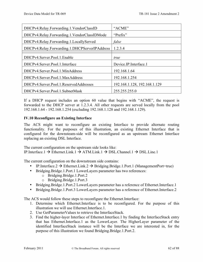
Device Data Model for TR-069 TR-181 Issue 2 Amendment 2
February 2011 © The Broadband Forum. All rights reserved 62 of 88
DHCPv4.Relay.Forwarding.1.VendorClassID “ACME”
DHCPv4.Relay.Forwarding.1.VendorClassIDMode “Prefix”
DHCPv4.Relay.Forwarding.1.LocallyServed false
DHCPv4.Relay.Forwarding.1.DHCPServerIPAddress 1.2.3.4
DHCPv4.Server.Pool.1.Enable true
DHCPv4.Server.Pool.1.Interface Device.IP.Interface.1
DHCPv4.Server.Pool.1.MinAddress 192.168.1.64
DHCPv4.Server.Pool.1.MaxAddress 192.168.1.254
DHCPv4.Server.Pool.1.ReservedAddresses 192.168.1.128, 192.168.1.129
DHCPv4.Server.Pool.1.SubnetMask 255.255.255.0 If a DHCP request includes an option 60 value that begins with “ACME”, the request is forwarded to the DHCP server at 1.2.3.4. All other requests are served locally from the pool 192.168.1.64 - 192.168.1.254 (excluding 192.168.1.128 and 192.168.1.129).
IV.10 Reconfigure an Existing Interface The ACS might want to reconfigure an existing Interface to provide alternate routing functionality. For the purposes of this illustration, an existing Ethernet Interface that is configured for the downsteam-side will be reconfigured as an upstream Ethernet Interface replacing an existing DSL Interface. The current configuration on the upstream side looks like: IP.Interface.1 à Ethernet.Link.1 à ATM.Link.1 à DSL.Channel.1 à DSL.Line.1 The current configuration on the downstream side contains:
• IP.Interface.2 à Ethernet.Link.2 à Bridging.Bridge.1.Port.1 (ManagementPort=true) • Bridging.Bridge.1.Port.1 LowerLayers parameter has two references:
o Bridging.Bridge.1.Port.2 o Bridging.Bridge.1.Port.3
• Bridging.Bridge.1.Port.2 LowerLayers parameter has a reference of Ethernet.Interface.1 • Bridging.Bridge.1.Port.3 LowerLayers parameter has a reference of Ethernet.Interface.2
The ACS would follow these steps to reconfigure the Ethernet.Interface:
1. Determine which Ethernet.Interface is to be reconfigured. For the purpose of this illustration we will use Ethernet.Interface.1.
2. Use GetParameterValues to retrieve the InterfaceStack. 3. Find the higher-layer Interface of Ethernet.Interface.1 by finding the InterfaceStack entry
that has Ethernet.Interface.1 as the LowerLayer. The HigherLayer parameter of the identified InterfaceStack instance will be the Interface we are interested in, for the purpose of this illustration we found Bridging.Bridge.1.Port.2.

Device Data Model for TR-069 TR-181 Issue 2 Amendment 2
February 2011 © The Broadband Forum. All rights reserved 63 of 88
4. Use DeleteObject to remove Bridging.Bridge.1.Port.2. This removal will automatically clean up the InterfaceStack instances that connect Bridging.Bridge.1.Port.1 à Bridging.Bridge.1.Port.2 and Bridging.Bridge.1.Port.2 à Ethernet.Interface.1. Also, it will remove Bridging.Bridge.1.Port.2 from the LowerLayers parameter contained within Bridging.Bridge.1.Port.1.
5. Find the DSL.Line reference within the LowerLayer parameter of the InterfaceStack. 6. Follow the InterfaceStack up to the Ethernet.Link reference by looking at the
HigherLayer parameter in the current InterfaceStack instance and then finding the InterfaceStack instance containing that Interface within the LowerLayer parameter until the HigherLayer reference is the Ethernet.Link Interface. For the purpose of this illustration, we found Ethernet.Link.1.
7. Use SetParameterValues to reconfigure the LowerLayers parameter of Ethernet.Link.1 such that its value is “Device.Ethernet.Interface.1” instead of “Device.ATM.Link.1”.
8. The CPE updates the InterfaceStack table and sets the Upstream parameter to true on the Ethernet.Interface.1 instance automatically.
9. Note that the ACS might also want to update other related objects, including the NAT object, the Routing.Router object, or various QoS and Bridging tables. VLANs might also need to be created.
After the CWMP Session is completed and the CPE commits the configuration, the upstream side will look like: IP.Interface.1 à Ethernet.Link.1 à Ethernet.Interface.1
Device Data Model for TR-069 TR-181 Issue 2 Amendment 2
February 2011 © The Broadband Forum. All rights reserved 64 of 88
Appendix V: IPv6 Data Modeling Theory of Operation V.1 IPv6 Overview The IETF published RFC 2460 [16], Internet Protocol, Version 6 (IPv6) Specification in 1998. Since then, it has published a variety of RFCs to create a suite of protocols (and extensions to protocols) for operating, managing, and configuring IPv6 networks and devices. In addition there are RFCs that document transition mechanisms (to transition from IPv4 to IPv6) and best current practices (that describe which RFCs to implement depending on what a device is or needs to do). The Broadband Forum has published several Technical Reports describing IPv6 architectures and device requirements. Specifically, TR-124 Issue 2 [30] includes IPv6 requirements for Residential Gateways (RGs), TR-177 [31] describes migration to IPv6 in the context of TR-101 [29], and TR-187 [32] describes an architecture for IPv6 for PPP Broadband Access. The TR-181i2 IPv6 Data Model is intended to ensure that TR-069-managed [2] End Devices, RGs, and other Network Infrastructure Devices can be managed and configured, consistent with the requirements listed in these documents. The basic elements of IPv6 data modeling involve information on IPv6 capabilities, and enabling those capabilities on devices and device interfaces (see Section V.3), configuring addresses, prefixes , and configuration protocols on upstream and downstream interfaces (see Sections V.4 and V.5), interacting with other devices on the Local Area Network (LAN) (see Section V.6), and configuring IPv6 routing and forwarding information (see Section V.7). Configuration protocols include Neighbor Discovery (ND; RFC 4861 [22]) and DHCPv6 (RFC 3315 [18]). Neighbor Discovery includes several messages that are important to configuration, including Router Solicitation (RS) [sent by devices looking for routers], Router Advertisement (RA) [sent by routers to other devices on the LAN], Neighbor Solicitation (NS) [used to identify if any other device on the LAN is using the same IPv6 address, and used to see if previously detected devices are still present; the latter is called Neighbor Unreachability Detection (NUD)], and Neighbor Advertisement (NA) [used to respond to a NS sent to one of the device’s IPv6 addresses]. These messages are central to the stateless address autoconfiguration (SLAAC) mechanism described in RFC 4862 [23]. SLAAC is expected to be the primary means of IPv6 address configuration for devices inside a home network. RFC 4191 [20] extended the RA message to support a RouteInformation option. RFC 6106 [26] extended the RA message to support sending Recursive DNS Servers (RDNSS) information for DNS configuration. DHCPv6 can also be used for IPv6 address provisioning, through its IA_NA option. DHCPv6 was extended by RFC 3633 [19] to provide the IA_PD option for delegating IPv6 prefixes to routers (that the routers can then use to provide IPv6 addresses to other devices on the LAN, or to further sub-delegate to other routers inside the LAN). Both IA_NA and IA_PD require the DHCPv6 server to maintain state for these assignments (since they have lifetimes, can expire, and require renewal). DHCPv6 can also supply a variety of stateless configuration options, including recursive DNS server information. RGs can have both DHCPv6 client and server, and it may be desirable for some of the stateless options to be passed through from the client to the server.

Device Data Model for TR-069 TR-181 Issue 2 Amendment 2
February 2011 © The Broadband Forum. All rights reserved 65 of 88
Interfaces that support IPv6 will have more than one IPv6 address. IPv6 interfaces are always required to have a link-local address (described in RFC 4862 [23]). Other IPv6 addresses may be acquired through SLAAC, DHCPv6 IA_NA, or they may be statically configured. Routers may acquire prefixes (for use with address assignment in the LAN) from DHCPv6 IA_PD, static configuration, or by generating their own Unique Local Address (ULA) prefixes from a self-generated ULA Global ID (RFC 4193 [21]). Because of the various IPv6 addresses that devices can have, maintaining good routing table and IPv6 forwarding information is critical. Route information can be obtained from received RA messages (both by noting that the sending device is a router, and from the RouteInformation option) as well as other protocols.
V.2 Data Model Overview This Theory of Operations focuses on data modeling for the purpose of establishing upstream and downstream connectivity for TR-069-enabled [2] devices, and for configuration of IPv6-related parameters. This is not an exhaustive description of data model changes made in support of IPv6, and only intends to describe the working of elements that are not readily obvious. The following tables are key to IPv6 data modeling:
• IP o IP.Interface
§ IP.Interface.IPv6Address § IP.Interface.IPv6Prefix
• PPP.Interface • Routing.Router
o Routing.Router.IPv6Forwarding o Routing.RouteInformation.InterfaceSetting
• NeighborDiscovery.InterfaceSetting • RouterAdvertisement.InterfaceSetting
o RouterAdvertisement.InterfaceSetting.Option • Hosts.Host • DHCPv6
o DHCPv6.Client § DHCPv6.Client.Server § DHCPv6.Client.SentOption § DHCPv6.Client.ReceivedOption
o DHCPv6.Server § DHCPv6.Server.Pool
• DHCPv6.Server.Pool.Client o DHCPv6.Server.Pool.Client.IPv6Address o DHCPv6.Server.Pool.Client.IPv6Prefix

Device Data Model for TR-069 TR-181 Issue 2 Amendment 2
February 2011 © The Broadband Forum. All rights reserved 66 of 88
o DHCPv6.Server.Pool.Client.Option • DHCPv6.Server.Pool.Option
Note that the following tables have separate theories of operation, and are not described again here:
• IPv6rd.InterfaceSetting • DSLite.InterfaceSetting
Firewall includes some IPv6 elements that are not described, since it does not interact with tables other than an association with IP.Interface. As such, its IPv6 usage is considered straightforward, and explanation is considered unnecessary. Similarly, DNS.Client.Server is not described. Use of DHCPv6 elements of Bridging.Filter are also not described, as there is no conceptual difference between how they are used and how DHCPv4 elements are used. Figure 20 shows the relationship of IPv6 configuration messages to devices and the tables used to configure the protocol messages and store the responses.

Device Data Model for TR-069 TR-181 Issue 2 Amendment 2
February 2011 © The Broadband Forum. All rights reserved 67 of 88
Figure 20 – Relationship of Protocols to Data Model
Figure 21 shows internal relationships of parts of the data model involved in IPv6 addresses and IPv6 prefixes. The following sections describe in greater detail how these various tables are populated.
Has physical upstream and downstream interfaces. If there is an upstream IP interface (to allow for device configuration), then it can do RS and NS to configure IP addresses on its upstream IP interface.
Routed RG
Wireless Access Point (bridged) (Network
Infrastructure Device) End Device
Routed RG
End Device RS
RA
DHCPv6 client messages DHCPv6 server messages
RS RA
NS DHCPv6 client messages
DHCPv6 server messages
RS RA NS
DHCPv6 client messages DHCPv6 server messages
RS RA NS
downstream
upstream interfaces: • RS configured in NeighborDiscovery • DHCPv6 client configured in DHCPv6.Client • RA PrefixInformation prefixes stored in • IP.Interface.IPv6Prefix • RA “A” prefixes used to create IP.Interface.IPv6Address
instances • RA RouteInformation prefixes go in
Routing.Router.IPv6Forwarding • DHCPv6 server IA_NA stored in IPv6Address, IA_PD in
IPv6Prefix, other options in DHCPv6.Client.ReceivedOption
• NS for NUD configured in NeighborDiscovery
upst
ream
downstream interfaces: • RA configured in
RouterAdvertisement • DHCPv6 server configured in
DHCPv6.Server [may include references to allow pass-through of stateless options from a DHCPv6.Client]
• NS for NUD configured in NeighborDiscovery
downstream
upst
ream
downstream
upst
ream
upst
ream
upst
ream

Device Data Model for TR-069 TR-181 Issue 2 Amendment 2
February 2011 © The Broadband Forum. All rights reserved 68 of 88
Figure 21 – Internal Relationships of IPv6 Addresses and Prefixes
V.3 Enabling IPv6 The IP IPv6Capable parameter indicates whether the device supports IPv6. IP.IPv6Enable controls enabling IPv6 is on the device. IPv6 can only be enabled on a device with IPv6Capable=true. IPv6Status indicates whether IPv6 has been enabled on the device. Per TR-124 Issue 2 [30], the upstream interface can be configured to establish an IPv6 connection either over PPP (PPPoA or PPPoE) or directly over Ethernet. Both mechanisms require an IP.Interface instance with IPv6Enable set to true. When using PPP, a PPP.Interface instance must have IPv6CPEnable set to true (which can only occur if PPP.SupportedNCPs includes IPv6CP in its list of Network Control Protocols (NCPs)). Enabling IPv6 on specific downstream or upstream interfaces requires that IP.Interface instances have IPv6Enable set to true.
V.4 Configuring Upstream IP Interfaces An upstream IP Interface is an IP.Interface that is associated with an Upstream=true physical interface, via the InterfaceStack. Every Upstream=true physical interface that will be used to

Device Data Model for TR-069 TR-181 Issue 2 Amendment 2
February 2011 © The Broadband Forum. All rights reserved 69 of 88
support routed IPv6 traffic will have an upstream IP Interface for each distinct upstream IPv6 connection that is established over that physical interface. Upstream IPv6 connections can be established on an upstream IP Interface either through internal logic (for well-known addresses and the link-local address), static configuration, or dynamically through received Router Advertisement (RA) messages or DHCPv6 client behaviors. Received RA and DHCPv6 messages can contain configuration information for more than just establishing the upstream IP interface. The data model allows for the storage of additional configuration information sent by one of these protocols.
V.4.1 Configuration Messages Sent Out the Upstream IP Interface The device can be configured to send Router Solicitation and DHCPv6 client messages out an upstream IP interface.
• A device that is configured to send Router Solicitation messages out an upstream IP interface will have a NeighborDiscovery.InterfaceSetting instance whose Interface is the related upstream IP.Interface, and with RSEnable=true.
• A device that is configured to send DHCPv6 client requests out an upstream IP interface will have a DHCPv6.Client instance whose Interface is the related upstream IP.Interface, and with Enable=true. RequestAddresses indicates whether IA_NA is to be requested, RequestPrefixes indicates whether IA_PD is to be requested, and RequestedOptions identifies which other options are to be requested. DHCPv6.Client.Server, DHCPv6.Client.SentOption, and DHCPv6.Client.ReceivedOption are populated as appropriate, as described in the data model.
V.4.2 IPv6 Prefixes IP.Interface.IPv6Prefix instances on upstream IP interfaces are used to store all prefixes received in RA messages on the interface (with Origin of RouterAdvertisement), prefixes delegated by DHCPv6 IA_PD (with Origin of PrefixDelegation), statically configured IPv6 prefixes (but only the ones that are intended to be sub-divided for use on downstream interfaces with sent RA messages or DHCPv6 server functions), and WellKnown prefixes, as appropriate (such as certain well-known multicast prefixes, where the device joins the multicast group for that prefix on that interface). RouterAdvertisement prefixes with Autonomous=true are used to create an IPv6Address instance on the interface, and can be used to create routes in Routing.Router.IPv6Forwarding. RouterAdvertisement prefixes with OnLink=true can also be used to create routes in Routing.Router.IPv6Forwarding. Prefixes received in a RA RouteInformation option are not stored with the interface, but rather in an instance of Routing.RouteInformation.InterfaceSetting. PrefixDelegation prefixes and Static prefixes are not directly used on the upstream IP interface. They are prefixes that are intended to be sub-divided for use on the device’s downstream interfaces, either by the DHCPv6 server for IA_NA or IA_PD, sent in RA messages (as on-link and/or autonomous prefixes), or used to self-assign addresses to other interfaces on the device.

Device Data Model for TR-069 TR-181 Issue 2 Amendment 2
February 2011 © The Broadband Forum. All rights reserved 70 of 88
Non IA_PD prefixes received in DHCPv6 options are not stored with the upstream IP interface. Prefixes for static routes are entered directly into Routing.Router.IPv6Forwarding and do not need to also have upstream IP interface IPv6Prefix entries. It is often desirable to configure information about delegated prefixes before they have been delegated (for example, that a particular /64 of that prefix is to be used on the downstream interface for address assignment). In order to allow for the referencing of not-yet-existing-but-expected delegated prefixes, an Origin=Static IPv6Prefix entry is created of Type=PrefixDelegation. When a device receives a delegated prefix, it is expected to first look for such Static entries and populate them with the delegated prefix information, instead of creating a new IPv6Prefix instance of Origin=PrefixDelegation. How these references are configured on downstream interfaces is discussed in Section V.5.1.
V.4.3 IPv6 Addresses IPv6 link-local addresses on an upstream IP Interface are generally internally generated, although they can be configured statically, when necessary (when the internal default link-local address fails Duplicate Address Detection (DAD)). A properly configured upstream IP.Interface instance will have a IP.Interface.IPv6Address instance for its link-local address. This will have Origin of AutoConfigured (if internally generated per RFC 4862 [23]) or Static (if statically configured by some management entity). IPv6 addresses that are created via stateless address autoconfiguration (SLAAC), as defined in RFC 4862 (from received RA messages that contain prefix(es) with Autonomous=true) cause the device to create a IP.Interface.IPv6Address instance with Origin of AutoConfigured. IPv6 addresses assigned via DHCPv6 IA_NA cause the device to create a IP.Interface.IPv6Address instance with Origin of DHCPv6. Statically created IPv6 addresses will have Origin of Static. If any of these addresses are Global Unicast Addresses (GUA), they can be used to originate and terminate traffic to/from either the downstream or the upstream, independent of which physical interface they are associated with.
V.5 Configuring Downstream IP Interfaces A downstream IP Interface is a IP.Interface that is associated with an Upstream=false physical interface, via the InterfaceStack. As noted in the definition of the Upstream parameter, “For an End Device, Upstream will be true for all interfaces.” This means that only RGs or (possibly) other Network Infrastructure Devices will have downstream IP Interfaces.
V.5.1 IPv6 Prefixes IP.Interface.IPv6Prefix instances on downstream IP interfaces are used to store all prefixes that are either on-link for that downstream IP interface, or can be delegated to or used by routers connected to that downstream IP interface. On-link prefixes include prefixes that are included in Router Advertisement (RA) messages for SLAAC (Autonomous prefixes), those used as DHCPv6 address pools, and those used for static addressing by End Devices that connect to that downstream IP interface. The device can have a Unique Local Address (ULA) /48 prefix defined in IP.ULAPrefix. In general, the device will generate its own ULA /48 prefix, although this value could be configured

Device Data Model for TR-069 TR-181 Issue 2 Amendment 2
February 2011 © The Broadband Forum. All rights reserved 71 of 88
directly by the user or through TR-069 [2]. If ULA addressing is to be supported on a downstream interface, then IP.Interface.ULAEnable must be true. The ULA /48 prefix can be associated with any downstream IP interface, and can be sub-divided to provide ULA prefixes on multiple downstream IP interfaces (by assigning longer prefixes from the ULA /48 prefix to these downstream IP interfaces). When the device creates a ULA prefix on a downstream interface, it creates an IPv6Prefix instance with Origin=AutoConfigured. RGs that are configured to act as routers need to know which prefixes to include in their sent Router Advertisement (RA) messages and to be used in DHCPv6 server pools. These prefixes need to be associated with the downstream IP interface for those RouterAdvertisement.InterfaceSetting and DHCPv6.Server.Pool instances. These prefixes can be statically configured on the downstream IP interface, or they can be automatically generated from prefixes on an upstream IP interface with Origin of PrefixDelegation or Static, or they can be generated from the ULA /48 prefix (as described in the previous paragraph). Prefixes that are automatically (by internal code) derived from prefixes on an upstream IP interface with Origin of PrefixDelegation or Static, will point to that upstream IP interface in ParentPrefix and have Origin of Child. It is often desirable to pre-configure information about prefixes on a downstream IP interface that are to be derived from delegated (on the upstream interface) prefixes. This will need to be done before that prefix has been delegated and without knowledge of what that prefix will be. A derived-from-not-yet-existing-but-expected-delegated-prefix downstream IP interface IPv6Prefix entry will have Origin=Static and Type=Child, and will have ParentPrefix pointing to an upstream IP interface IPv6Prefix instance (that is Origin=Static and Type= PrefixDelegation). When a device receives a delegated prefix and populates the upstream IP interface IPv6Prefix instance, and needs to generate downstream IP interface prefixes from that delegated prefix, it is expected to first look for such Static Child entries and populate them with the derived prefix information, instead of creating a new IPv6Prefix instance of Origin=Child. How the referenced parent prefixes are configured on upstream IP interfaces is discussed in Section V.4.2. If the device receives RA messages on downstream IP interfaces, autonomous and on-link prefixes in such received RA message Prefix Information options can also be recorded in IP.Interface.IPv6Prefix. At this time, there is no additional guidance for using the information in these RA messages received on downstream interfaces. They are simply stored, to provide information about other devices in the home network.
V.5.2 IPv6 Addresses As with the upstream IP interfaces, IPv6 link-local addresses on a downstream IP interface are generally internally generated, although they can be configured statically, when necessary (when the internal default link-local address fails Duplicate Address Detection (DAD)). A properly configured downstream IPv6 connection will have a IP.Interface instance with a IP.Interface.IPv6Address instance for its link-local address. This will have Origin of AutoConfigured (if internally generated per RFC 4862 [23]) or Static (if statically configured by some management entity).

Device Data Model for TR-069 TR-181 Issue 2 Amendment 2
February 2011 © The Broadband Forum. All rights reserved 72 of 88
If the device has a Unique Local Address (ULA) prefix that it is advertising and/or sub-delegating to devices on the LAN, then it needs to have at least one address from this prefix assigned to downstream IP interfaces that expect to support usage of the ULA. If the device did not receive an address on its upstream IP interface (from DHCPv6 or SLAAC), but it was delegated a prefix (DHCPv6 IA_PD), then it is expected to assign an address from a prefix (Origin=Child or Type=Child) derived from that delegated prefix to one of its non-upstream interfaces. This IPv6Address instance will have Origin of AutoConfigured. This address can be used for originating and terminating messages to and from either the downstream or the upstream interfaces.
V.6 Device Interactions The RG can interact with other devices on the LAN both by actively sending messages with or without configuration information, and by passively listening to messages received from other devices. End Devices can interact with other devices on the LAN by passively listening to messages received from other devices and by actively performing Neighbor Unreachability Detection (NUD) to determine if previously detected devices are still reachable.
V.6.1 Active Configuration To assist in the automated configuration of other devices on the LAN, an RG sends Router Advertisement (RA) messages and DHCPv6 server messages. This function is associated with downstream IP interfaces, and thus does not apply to End Devices. As noted in the above section on downstream IP interfaces, only RGs or other infrastructure devices will have downstream IP interfaces.
• RouterAdvertisement.InterfaceSetting instances whose Interface is the related downstream IP.Interface, with Enable=true, define the content of RA messages that get sent on the downstream IP interface. The RouterAdvertisement.InterfaceSetting instance will include references to IPv6Prefix entries in the associated downstream IP interface. These are IPv6Prefix entries of Origin=Child or Origin=Static.
• DHCPv6.Server.Pool instances whose Interface is the related downstream IP.Interface, with Enable=true, contain information for filtering DHCPv6 client requests, and identify the IPv6 prefix(es) (references to IPv6Prefix entries of the associated downstream IP interface) that provide the pool of IPv6 addresses and IPv6 prefixes available for assignment from this pool. Information on soliciting clients (including assigned addresses and prefixes and received option information) is stored in DHCPv6.Server.Pool.Client. Additional options that are sent to soliciting clients is stored in DHCPv6.Server.Pool.Option. The PassthroughClient parameter in this table identifies whether the value of this option is simply passed through from a DHCPv6 client on an upstream interface.

Device Data Model for TR-069 TR-181 Issue 2 Amendment 2
February 2011 © The Broadband Forum. All rights reserved 73 of 88
As noted above, both RouterAdvertisement.InterfaceSetting and DHCPv6.Server.Pool have references to IPv6Prefix entries. The ManualPrefixes, IANAManualPrefixes and IAPDManualPrefixes parameters allow for configuration (through TR-069 [2], user interface, or other means) of prefixes that are to be included in RA messages, and to be used in deriving DHCPv6 IA_NA and IA_PD offers, respectively. The Prefixes, IANAPrefixes, and IAPDPrefixes parameters list all of the prefixes that the devices actually does include in these messages. Since the *ManualPrefixes entries may point to IPv6Prefix entries that are not enabled, it is possible that not all of those will be included in these parameters’ lists. In addition to the *ManualPrefix entries, these lists may also include references to prefixes that the device creates or uses automatically in RA messages or for deriving DHCPv6 IA_NA or IA_PD offers. There is some flexibility in the modeling of ULA IA_PD prefixes. It is not required to model the ULA /48 prefix in an IPv6Prefix instance. If the ULA /48 is not represented in an IPv6Prefix instance and ULAEnable is true for a downstream interface and IAPDEnable is true for a DHCPv6.Server.Pool instance, then it can be assumed that the device will sub-delegate prefixes from the ULA /48 prefix. Alternately, the ULA /48 can be included as an AutoConfigured prefix in a downstream interface, and that IPv6Prefix instance can be referenced in IAPDPrefixes in the DHCPv6.Server.Pool instance. It is also possible to manually create a Static longer-than-/48 prefix from the ULA prefix in a downstream interface. This Static prefix can then be referenced in IAPDManualPrefix for a DHCPv6.Server.Pool instance for that interface. For IA_PD, there is one additional parameter: IAPDAddLength. This parameter is configured to recommend how many bits should be added to an IAPDPrefixes prefix to create a delegated prefix offer.
V.6.2 Monitoring All devices can monitor and record information from messages sent by other devices.
• Information received in Neighbor Solicitation (NS) and Neighbor Advertisement (NA) messages sent by other devices is recorded in Hosts.Host.
• In order to actively solicit information from other devices on the LAN, the device can have a NeighborDiscovery.InterfaceSetting instance whose Interface is the related downstream IP.Interface, and with NUDEnable=true. To determine whether there are other routers connected to the LAN that are behaving like IPv6 routers to this same LAN segment, this InterfaceSetting can also have RSEnable=true. However, it is not recommended that routers do this until there is better guidance available for routers that co-exist in a peered environment on the same LAN.
V.7 Configuring IPv6 Routing and Forwarding

Device Data Model for TR-069 TR-181 Issue 2 Amendment 2
February 2011 © The Broadband Forum. All rights reserved 74 of 88
IPv6 routing information is stored in instances of Routing.Router.IPv6Forwarding. This information can in part be derived from Router Advertisement (RA) messages, either directly from the address of the router sending the RA, or from RA RouteInformation (RFC 4191 [20]) options that may be included in the message. Routing.RouteInformation.InterfaceSetting instances record received RA RouteInformation options.
V.8 Configuring IPv6 Routing and Forwarding Following is an example of how a typical RG (one upstream and one downstream interface, with delegated prefix and IA_NA address, and ULA enabled) might be configured. The corresponding data model is shown below the figure. Not all parameters are shown, and objects and parameters that the ACS is likely to have explicitly created or written are shown in bold face (some of these settings might alternatively be present in the factory default configuration).

Device Data Model for TR-069 TR-181 Issue 2 Amendment 2
February 2011 © The Broadband Forum. All rights reserved 75 of 88

Device Data Model for TR-069 TR-181 Issue 2 Amendment 2
February 2011 © The Broadband Forum. All rights reserved 76 of 88
# IP IP. IPv6Capable = true IPv6Enable = true IPv6Status = "Enabled" ULAPrefix = fd01:2345:6789::/48 # typically generated by CPE # Router Solicitation (Upstream IP interface) NeighborDiscovery. Enable = true InterfaceSetting.1. Enable = true Interface = IP.Interface.1 RSEnable = true # DHCPv6 Client (Upstream IP interface) DHCPv6.Client.1 Enable = true Interface = IP.Interface.1 RequestAddresses = true RequestPrefixes = true # Upstream IP interface # - Assumes DHCPv6 IA_PD will be 1080:0:0:800::/56 (this is NOT known at # configuration time). # - Assumes RA(PI) will be 2001:0DB8::/64 (this is NOT known at configuration # time) # - Assumes link-layer address is 55:44:33:22:11:00 # [Section 4/RFC 2464[17]],[Section 4.1/RFC 5072[24]] IP.Interface.1 Enable = true IPv6Enable = true # Upstream IP interface IPv6 prefixes # - Assumes that the WellKnown Link Local fe80::/10 prefix not modeled IPv6Prefix.1 Enable = true Prefix = 1080:0:0:800::/56 # DHCPv6(IA_PD) [RFC 3633[19]] Origin = "Static" StaticType = "PrefixDelegation"
# Upstream IP interface IPv6 addresses (LL, GUA) IPv6Address.1 Enable = true IPAddress = fe80::5544:33ff:fe22:1100 Origin = "AutoConfigured" # LL Prefix = "" IPv6Address.2 Enable = true IPAddress = 1080:0:0:700:: Origin = "DHCPv6" # GUA (from IA_NA [RFC 3315[18]]) Prefix = "" # Downstream IP interface # - Assumes link-layer address is 00:11:22:33:44:55 [Section 4/RFC 2464[17]]

Device Data Model for TR-069 TR-181 Issue 2 Amendment 2
February 2011 © The Broadband Forum. All rights reserved 77 of 88
IP.Interface.2 Enable = true IPv6Enable = true ULAEnable = true
# Downstream IP interface IPv6 prefixes IPv6Prefix.1 Enable = true Prefix = 1080:0:0:800::/64 Origin = "Static" StaticType = "Child" # IA_PD /64 (for lcl, RA and IA_NA) ParentPrefix = IP.Interface.1.IPv6Prefix.1 ChildPrefixBits = 0:0:0:00::/64 IPv6Prefix.2 Enable = true Prefix = 1080:0:0:810::/60 Origin = "Static" StaticType = "Child" # IA_PD /60 (for IA_PD) ParentPrefix = IP.Interface.1.IPv6Prefix.1 ChildPrefixBits = 0:0:0:10::/60
IPv6Prefix.3 Enable = true Prefix = fd01:2345:6789::/48 Origin = "AutoConfigured" # ULA /48 IPv6Prefix.4 Enable = true Prefix = fd01:2345:6789:0::/64 Origin = "AutoConfigured" # ULA /64 (for lcl, RA and IA_NA) IPv6Prefix.5 Enable = true Prefix = 2001:0db9::/60 # RA(PI) [RFC 4861[22]] Origin = "RouterAdvertisement" # from peer router Autonomous = true OnLink = true # Downstream IP interface IPv6 addresses (LL, GUA?, ULA) IPv6Address.1 Enable = true IPAddress = fe80::0011:22ff:fe33:4455 Origin = "AutoConfigured" # LL Prefix = "" IPv6Address.2 Enable = false # have upstream GUA so disabled IPAddress = 1080:0:0:800:: Origin = "AutoConfigured" # GUA (from IA_PD /64) Prefix = IP.Interface.2.IPv6Prefix.1 IPv6Address.3 Enable = true IPAddress = fd01:2345:6789::0011:22ff:fe33:4455 Origin = "AutoConfigured" # ULA (from ULA /64) Prefix = IP.Interface.2.IPv6Prefix.4 # Router Advertisement (Downstream IP interface) RouterAdvertisement. Enable = true InterfaceSetting.1 Enable = true

Device Data Model for TR-069 TR-181 Issue 2 Amendment 2
February 2011 © The Broadband Forum. All rights reserved 78 of 88
Interface = IP.Interface.2 ManualPrefixes = IP.Interface.2.IPv6Prefix.2 # DHCPv6 server (Downstream IP interface) DHCPv6.Server. Enable = true Pool.1 Enable = true Interface = IP.Interface.2 <filter criteria> IANAManualPrefixes = IP.Interface.2.IPv6Prefix.1 IAPDManualPrefixes = IP.Interface.1.IPv6Prefix.1, IP.Interface.2.IPv6Prefix.2 IAPDADDLength = 4

Device Data Model for TR-069 TR-181 Issue 2 Amendment 2
February 2011 © The Broadband Forum. All rights reserved 79 of 88
Appendix VI: 6rd Theory of Operation The Device:2 data model supports IPv68 via various IPv6-specific objects and parameters that are designed to be used with other IP version neutral and IPv4-specific objects and parameters. This Appendix briefly reviews all the relevant objects and parameters, and then presents some example configurations.
VI.1 RFC 5969 Configuration Parameters RFC 5969 [25] describes the general operation of the 6rd protocol and configuration of external parameters needed to do the protocol. Table 14 shows the 6rd configuration parameters defined in RFC 5969 and their mapping into the Device:2 data model. Refer to RFC 5969 for further description on use of these parameters. Note that while RFC 5969 allows for multiple Border Relay (BR) IPv4 addresses, it does not describe how a device selects from among these. The device will need to have internal logic to handle this case, but service providers might wish to ensure that they know what the behavior will be, if they intend to supply multiple BR addresses.
Table 14 – RFC 5969 Configuration Parameter Mapping RFC 5969 (Section 7) Configuration Parameter Device:2 (IPv6rd.InterfaceSetting.{i}) Parameter
IPv4MaskLen IPv4MaskLength 6rdPrefix
SPIPv6Prefix (expressed with prefix length) 6rdPrefixLen 6rdBRIPv4Address BorderRelayIPv4Addresses
VI.2 Internal Configuration Parameters AddressSource, TunnelInterface, TunneledInterface, and AllTrafficToBorderRelay parameters are used to define internal device operation. AddressSource allows the desired source IPv4 address to be selected (to be embedded in the 6rd IPv6 address, after removing IPv4MaskLength bits from the beginning of the address, and as the source IPv4 address of the encapsulating IPv4 header). TunnelInterface and TunneledInterface allow for internal forwarding, routing, encapsulation, classification and marking of IPv6 packets. AllTrafficToBorderRelay impacts determination of the IPv4 destination address of the encapsulating IPv4 header.
VI.3 IPv4 Address Source In general, it is expected that the device will use the IPv4 address obtained on the upstream interface as the address that is embedded in the 6rd IPv6 address, and used as the encapsulating source IPv4 address. However, there could be cases where the device has other public IPv4 addresses assigned to it, and it would be preferable to use one of these. For example, if the
8 Introduced in Amendment 2

Device Data Model for TR-069 TR-181 Issue 2 Amendment 2
February 2011 © The Broadband Forum. All rights reserved 80 of 88
device has a public static IP address assigned to a different interface, it could be desired to use that address instead of the address assigned to the upstream interface. If this parameter is not present, or if it is an empty string, the device will use internal logic to determine the source IPv4 address. In cases where there is a single upstream interface with an assigned (e.g. DHCPv4, IPCP, static) IPv4 address, that is the address that will be used. Note that service providers need to be careful when using alternate addresses. If the alternate address does not have the same higher order IPv4 bits as other devices that will be supported by the same 6rd prefix, then the IPv4 mask will need to be zero. Masked IPv4 bits will be the same for all IPv4 addresses within a 6rd domain, per RFC 5969 [25].
VI.4 Sending All Traffic to the Border Relay Server The default behavior of a 6rd client device is that all IPv6 packets are encapsulated in IPv4 packets with destination address of a 6rd border relay server, except when the IPv6 destination address begins with SPIPv6Prefix. When the destination IPv6 address begins with SPIPv6Prefix, then the encapsulating IPv4 destination address is derived from the IPv6 destination address by taking the next 32 - IPv4MaskLength bits, pre-pending the bits that are masked (as determined by its own WAN IPv4 address), and using the resulting IPv4 address as the encapsulating destination IPv4 address. For example, if
• the IPv6 destination address is 2001:db8:64c8:200:x:x:x:x [note 64 hex = 100 decimal, c8 hex = 200 decimal, leading zeroes between colons are not shown]
• the SPIPv6Prefix is 2001:db8::/32 • the device’s WAN IPv4 address is 10.100.100.1 • IPv4MaskLength is 8 • advertised-to-LAN SLAAC prefix of 2001:db8:6464:100::/64
…then the encapsulation destination IPv4 address becomes the first 8 bits of the device’s WAN IPv4 address (10 for an address of 10.100.200.2), plus the next 24 bits (32-8=24) after the SPIPv6Prefix (next 24 bits are 64c802 hex = 100.200.2 binary). The source encapsulating IPv4 address is 10.100.100.1. The source IPv6 address begins with the prefix 2001:db8:6464:100::/64. However, if AllTrafficToBorderRelay is True, then all external-bound IPv6 traffic is sent to the border relay. This Boolean field is reflected in the routing table. If the value is False (default behavior), then the IPv6 routing table for this example (with a border relay IPv4 address of 10.0.0.1) would include the following entries: ::/0 -> 6rd-tunnel-interface-int0 via 2001:db8:0:100::
(default route to border relay) 2001:db8::/32 -> 6rd-tunnel-interface-int0
(direct connect to 6rd tunnel interface if the first 32 bits of destination address match SPIPv6Prefix)
2001:db8:6464:100::/64 -> Ethernet0 (downstream interface)

Device Data Model for TR-069 TR-181 Issue 2 Amendment 2
February 2011 © The Broadband Forum. All rights reserved 81 of 88
If the AllTrafficToBorderRelay field is true, then the 2nd entry above does not exist
VI.5 Internal Treatment of IPv6 Packets Since a device can have multiple upstream and multiple downstream interfaces, the model supports logical representations of the internal virtual 6rd IPv6 interface and the virtual IPv4-encapsulated 6rd interface. The two are separated within the model so that classification and marking can occur for both the un-encapsulated IPv6 packet and the IPv4- encapsulated packet. The internal virtual 6rd IPv6 interface is TunnelInterface. The internal virtual IPv4-encapsulated 6rd interface is TunneledInterface. The IPv6Forwarding entries (which correspond to the routing table entries mentioned above) will route traffic between the downstream IPv6 interfaces and the 6rd IPv6 interface. IPv4Forwarding entries are unaffected. Figure 22 shows the flow of tunneled 6rd traffic through the downstream, upstream, and logical tunnel/tunneled interfaces. Noted in the figure are sample values for the various IP.Interface entries that would be needed. Figure 23 shows an upstream traffic example for how the tunnel/tunneled logical interfaces are also used to describe the path 6rd traffic flows in going through Device QoS for purpose of classification, policing, and marking, for both the IPv6 packets (Tunnel) and the encapsulating IPv4 packets (Tunneled).
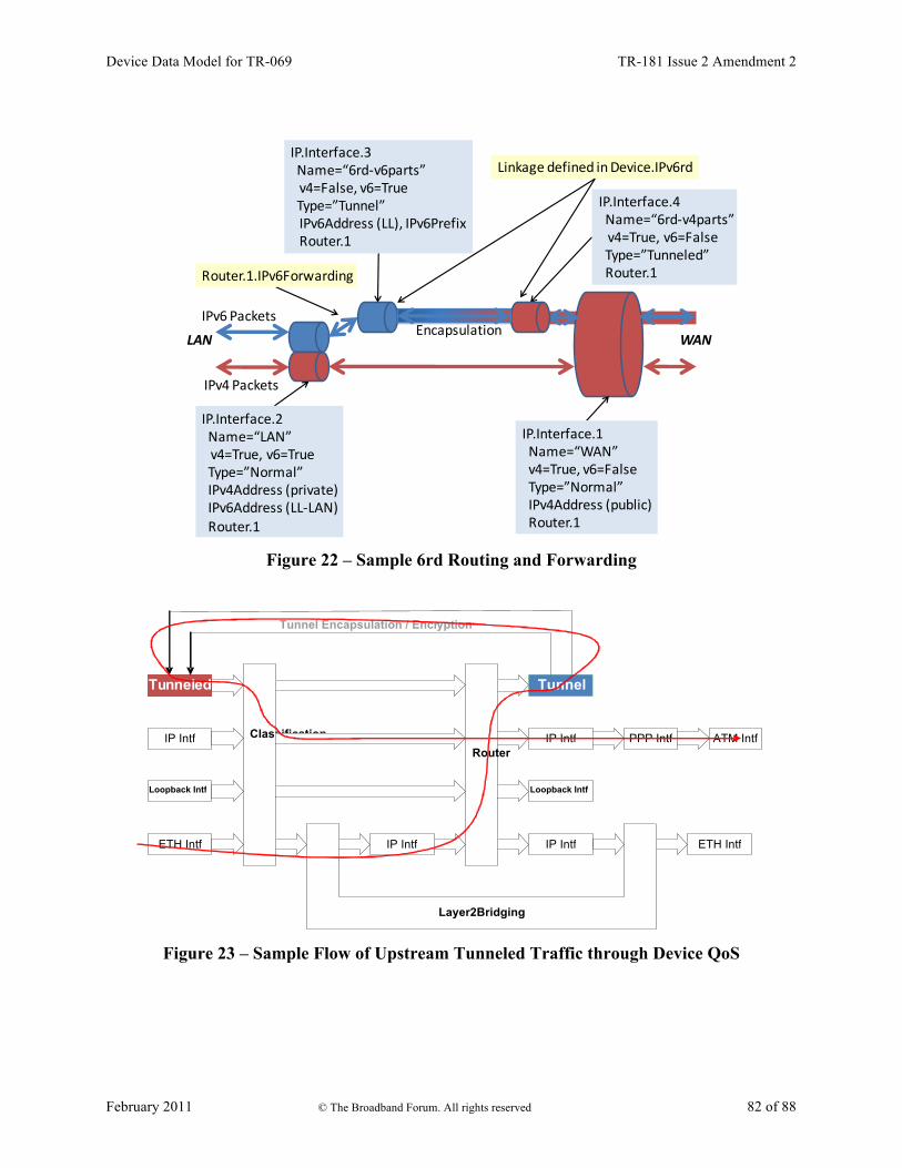
Device Data Model for TR-069 TR-181 Issue 2 Amendment 2
February 2011 © The Broadband Forum. All rights reserved 82 of 88
IPv6 Packets
IPv4 Packets
LAN WAN
IP.Interface.2Name=“LAN”v4=True, v6=True Type=”Normal”IPv4Address (private)IPv6Address (LL-‐LAN)Router.1
IP.Interface.1Name=“WAN”v4=True, v6=FalseType=”Normal”IPv4Address (public)Router.1
Router.1.IPv6Forwarding
IP.Interface.3Name=“6rd-‐v6parts”v4=False, v6=True Type=”Tunnel”IPv6Address (LL), IPv6PrefixRouter.1
Linkage defined in Device.IPv6rd
IP.Interface.4Name=“6rd-‐v4parts”v4=True, v6=FalseType=”Tunneled”Router.1
Encapsulation
Figure 22 – Sample 6rd Routing and Forwarding
Figure 23 – Sample Flow of Upstream Tunneled Traffic through Device QoS
Layer2Bridging
Router
Classification
IP Intf
Tu n nel ed
Loopback Intf
ETH Intf IP Intf IP Intf
Loopback Intf
ETH Intf
Tunnel
IP Intf PPP Intf ATM Intf
Tunnel Encapsulation / Encr yption

Device Data Model for TR-069 TR-181 Issue 2 Amendment 2
February 2011 © The Broadband Forum. All rights reserved 83 of 88
Appendix VII: Dual-Stack Lite Theory of Operation draft-ietf-softwire-dual-stack-lite [27] describes the general operation of the dual-stack lite (DS-Lite) technology and configuration of external parameters needed to do the protocol. Table 15 shows the DS-Lite configuration parameters defined and required in draft draft-ietf-softwire-dual-stack-lite [27] and further defined in draft draft-ietf-softwire-ds-lite-tunnel-option [28] and their mapping into the Device:2 data model9.
Table 15 – Draft Configuration Parameter Mapping Draft Device:2 (DSLite.InterfaceSetting.{i}) Parameter IPv6 address of the AFTR EndpointAddress Name of the AFTR EndpointName
EndpointAddress is a 128 bit tunnel-endpoint-addr field, containing one IPv6 address. The tunnel EndpointAddress specifies the location of the remote tunnel endpoint, expected to be located at an AFTR (Address Family Transition Router). EndpointAddress can be assigned statically (e.g. present in the factory default configuration or set by the ACS) or dynamically (via DHCPv6). If both statically and dynamically assigned, then the EndpointAssignmentPrecedence parameter indicates whether it is the static configuration or the DHCPv6 configuration that is actually applied to EndpointAddress. EndpointName is a variable length tunnel-endpoint-name field, containing a Fully Qualified Domain Name that refers to the AFTR the client is requested to establish a connection with. EndpointName can be assigned statically (e.g. present in the factory default configuration or set by the ACS) or dynamically (via DHCPv6). If both statically and dynamically assigned, then the EndpointAssignmentPrecedence parameter indicates whether it is the static configuration or the DHCPv6 configuration that is actually applied to EndpointName. When EndpointName is assigned, the name is looked up (resolved) and the corresponding IPv6 address is set in EndpointAddress. When DS-Lite is running in the CPE, the NAT function is disabled between the LAN and DSLite interface.
VII.1 Internal Treatment of IPv4 Packets Since a device can have multiple upstream and multiple downstream interfaces, the model supports logical representations of the internal virtual DS-Lite IPv4 interface and the virtual IPv4-in-IPv6 encapsulated interface. The two are separated within the model so that classification and marking can occur for both the un-encapsulated IPv4 packet and the IPv6-encapsulated packet. The internal virtual DS-Lite entry (IPv4 interface) is TunnelInterface.
9 Introduced in Amendment 2

Device Data Model for TR-069 TR-181 Issue 2 Amendment 2
February 2011 © The Broadband Forum. All rights reserved 84 of 88
The internal virtual DS-Lite exit (IPv4 in IPv6 encapsulated) interface is TunneledInterface. The IPv4Forwarding entries will route traffic between the downstream IPv4 interfaces and the DS-Lite-entry interface. IPv6Forwarding entries are unaffected. Figure 24 shows the flow of tunneled DS-Lite traffic through the downstream, upstream, and logical tunnel/tunneled interfaces.
IPv4 Packets
IPv6 Packets
LAN WAN
IP.Interface.2Name=“LAN”v4=True, v6=True Type=”Normal”IPv4Address IPv6Address Router.1
IP.Interface.1Name=“WAN”v4=False, v6=TrueType=”Normal”IPv6Address Router.1
Router.1.IPv4Forwarding
IP.Interface.3Name=“DSLite-‐entry”v4=True, v6=False Type=”Tunnel”Router.1
Linkage defined in Device.DSLite
IP.Interface.4Name=“DSLite-‐exit”v4=False, v6=trueType=”Tunneled”Router.1
Figure 24 – Sample DS-Lite Routing and Forwarding
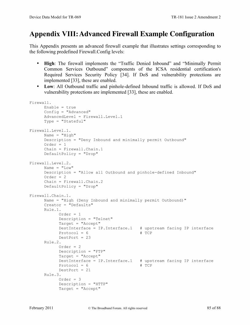
Device Data Model for TR-069 TR-181 Issue 2 Amendment 2
February 2011 © The Broadband Forum. All rights reserved 85 of 88
Appendix VIII: Advanced Firewall Example Configuration This Appendix presents an advanced firewall example that illustrates settings corresponding to the following predefined Firewall.Config levels:
• High: The firewall implements the “Traffic Denied Inbound” and “Minimally Permit Common Services Outbound” components of the ICSA residential certification's Required Services Security Policy [34]. If DoS and vulnerability protections are implemented [33], these are enabled.
• Low: All Outbound traffic and pinhole-defined Inbound traffic is allowed. If DoS and vulnerability protections are implemented [33], these are enabled.
Firewall.
Enable = true Config = "Advanced" AdvancedLevel = Firewall.Level.1 Type = "Stateful"
Firewall.Level.1.
Name = "High" Description = "Deny Inbound and minimally permit Outbound" Order = 1 Chain = Firewall.Chain.1 DefaultPolicy = "Drop"
Firewall.Level.2.
Name = "Low" Description = "Allow all Outbound and pinhole-defined Inbound" Order = 2 Chain = Firewall.Chain.2 DefaultPolicy = "Drop"
Firewall.Chain.1.
Name = "High (Deny Inbound and minimally permit Outbound)" Creator = "Defaults" Rule.1.
Order = 1 Description = "Telnet" Target = "Accept" DestInterface = IP.Interface.1 # upstream facing IP interface Protocol = 6 # TCP DestPort = 23
Rule.2. Order = 2 Description = "FTP" Target = "Accept" DestInterface = IP.Interface.1 # upstream facing IP interface Protocol = 6 # TCP DestPort = 21
Rule.3. Order = 3 Description = "HTTP" Target = "Accept"

Device Data Model for TR-069 TR-181 Issue 2 Amendment 2
February 2011 © The Broadband Forum. All rights reserved 86 of 88
DestInterface = IP.Interface.1 # upstream facing IP interface Protocol = 6 # TCP DestPort = 80
Rule.4. Order = 4 Description = "HTTPS" Target = "Accept" DestInterface = IP.Interface.1 # upstream facing IP interface Protocol = 6 # TCP DestPort = 443
Rule.5. Order = 5 Description = "SMTP" Target = "Accept" DestInterface = IP.Interface.1 # upstream facing IP interface Protocol = 6 # TCP DestPort = 25
Rule.6. Order = 6 Description = "DNS" Target = "Accept" DestInterface = IP.Interface.1 # upstream facing IP interface Protocol = 17 # UDP DestPort = 53
Rule.7. Order = 7 Description = "POP3" Target = "Accept" DestInterface = IP.Interface.1 # upstream facing IP interface Protocol = 6 # TCP DestPort = 110
Rule.8. Order = 8 Description = "IMAP" Target = "Accept" DestInterface = IP.Interface.1 # upstream facing IP interface Protocol = 6 # TCP DestPort = 143
Firewall.Chain.2.
Name = "Low (Allow all Outbound and pinhole-defined Inbound)" Creator = "Defaults" Rule.1.
Order = 1 Description = "Outbound" Target = "Accept" DestInterface = IP.Interface.1 # upstream facing IP interface
Rule.2. Order = 2 Description = "Allow IPsec AH" Target = "Accept" SourceInterface = IP.Interface.1 # upstream facing IP interface IPVersion = 6 # IPv6 Protocol = 51 # AH
Rule.3. Order = 3 Description = "Allow IPsec ESP"

Device Data Model for TR-069 TR-181 Issue 2 Amendment 2
February 2011 © The Broadband Forum. All rights reserved 87 of 88
Target = "Accept" SourceInterface = IP.Interface.1 # upstream facing IP interface IPVersion = 6 # IPv6 Protocol = 50 # ESP
Rule.4. Order = 4 Description = "Allow IPsec key exchange" Target = "Accept" SourceInterface = IP.Interface.1 # upstream facing IP interface IPVersion = 6 # IPv6 Protocol = 17 # UDP DestPort = 500
Rule.5. Order = 5 Description = "UPnP Port Mapping" Target = "TargetChain" TargetChain = Firewall.Chain.3 SourceInterface = IP.Interface.1 # upstream facing IP interface
Rule.6. Order = 6 Description = "UPnP IPv6 Firewall" Target = "TargetChain" TargetChain = Firewall.Chain.4 SourceInterface = IP.Interface.1 # upstream facing IP interface
Rule.7. Order = 7 Description = "User Interface" Target = "TargetChain" TargetChain = Firewall.Chain.5 SourceInterface = IP.Interface.1 # upstream facing IP interface
Firewall.Chain.3.
Name = "UPnP Port Mapping (dynamic rules)" Creator = "PortMapping" Rule.1.
Order = 1 Description = "SSH" Target = "Accept" SourceInterface = IP.Interface.1 # upstream facing IP interface IPVersion = 4 # IPv4 Protocol = 6 # TCP DestPort = 22
Firewall.Chain.4.
Name = "UPnP IPv6 Firewall (dynamic rules)" Creator = "WANIPv6FirewallControl" Rule.1.
Order = 1 Description = "HTTP" Target = "Accept" SourceInterface = IP.Interface.1 # upstream facing IP interface IPVersion = 6 # IPv6 Protocol = 6 # TCP DestIP = 1080:0:0:800::1 DestPort = 80
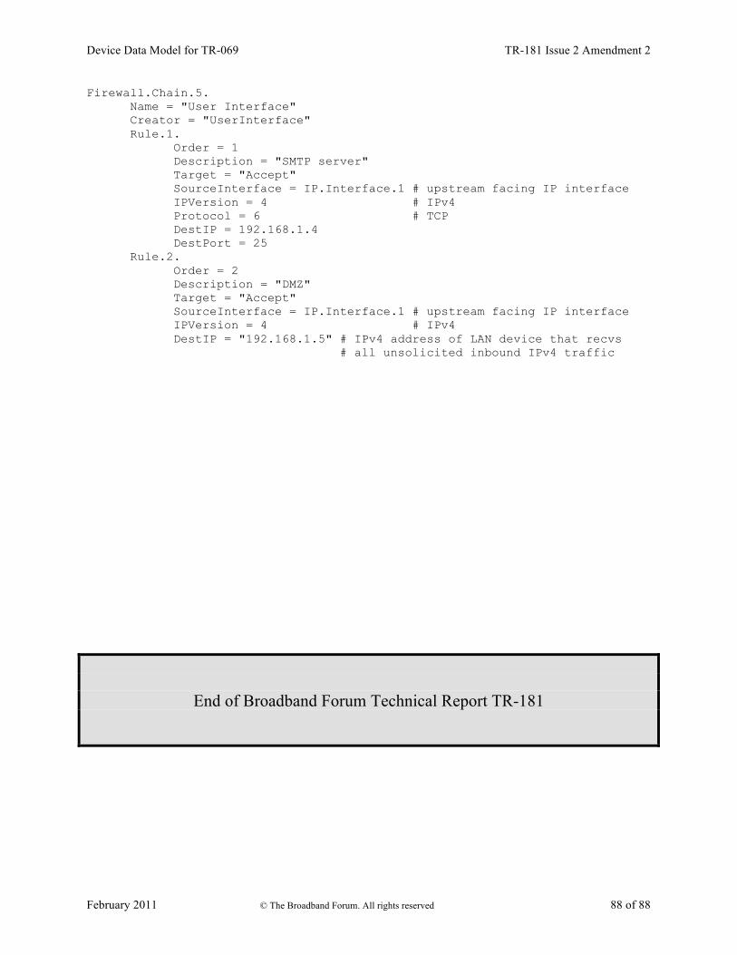
Device Data Model for TR-069 TR-181 Issue 2 Amendment 2
February 2011 © The Broadband Forum. All rights reserved 88 of 88
Firewall.Chain.5. Name = "User Interface" Creator = "UserInterface" Rule.1.
Order = 1 Description = "SMTP server" Target = "Accept" SourceInterface = IP.Interface.1 # upstream facing IP interface IPVersion = 4 # IPv4 Protocol = 6 # TCP DestIP = 192.168.1.4 DestPort = 25
Rule.2. Order = 2 Description = "DMZ" Target = "Accept" SourceInterface = IP.Interface.1 # upstream facing IP interface IPVersion = 4 # IPv4 DestIP = "192.168.1.5" # IPv4 address of LAN device that recvs
# all unsolicited inbound IPv4 traffic
End of Broadband Forum Technical Report TR-181